Embed Size (px)
Citation preview
Journal of Multidisciplinary Engineering Science and Technology (JMEST)
ISSN: 2458-9403
Vol. 5 Issue 10, October - 2018
www.jmest.org
JMESTN42352676 8847
Selection Of Deep Hole Drilling Parameters Under Cycle Time Requirement Based On Tool
Wear Analysis And Life Estimation
Cong Liao [email protected]
SoET, Purdue University, West Lafayette, Indiana 47907, USA
Haiyan Henry Zhang+
SoET, Purdue University, West Lafayette, Indiana 47907, USA
Yueen Li [email protected]
Shandong Jianzhu University, Jinan, Shandong, China
Abstract—The paper aims at analyzing the influence on tool wear of two cutting parameters: surface speed and feed, and estimating the tool life of the deep-hole drilling based specific solid twist dill bit and workpiece. The empirical equations are employed to produce a tool life optimization line, from which surface speed and feed with maximized tool life can be chosen to meet the product cycle time. By conducting a group of experiments, unknown variables in the equations are decided and the tool life is estimable. This technique is suitable for industry on deep-hole drilling applications to determine the cutting parameters based on their cost control and production needs. At the end of the paper, temperature on the cutting edge and cooling effect are also analyzed, and the notch on the coolant outlet holes are proposed to improve the cooling performance.
Keywords—deep-hole drilling, tool wear, cutting parameters, tool life estimation
1. Introduction
Generally, drilling a hole with depth to diameter ratio larger than 10:1 is considered deep-hole drilling. Due to the cramped cutting space, difficult chip breaking and removal, and high length to diameter ratio of cantilevered cutting which leads to weak system stiffness, deep-hole drilling is recognized as a problematic process [1]. The gun drilling and bore trepanning can also accurately machine deep holes, however, its critical disadvantage is time-consuming. Drilling with solid twist drill bit is one of the most commonly employed machining technologies with advantages of high productivity [2].
However, solid twist drill bit adopted for deep-hole drilling faces challenge of tool life problem. E. Abele
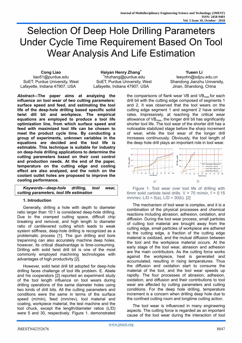
and his cooperators [2] reported an experiment study of the tool length influence on tool wears during drilling operations of the same diameter holes using two kinds of drill bits. All the cutting parameters and conditions were the same in terms of the surface speed (m/min), feed (mm/rev), tool material and coating, workpiece material, the test machine and the tool chuck, except the length/diameter ratios (L/D) were 5 and 30, respectively. Figure 1. demonstrated
the comparisons of flank wear VB and VBmax for each drill bit with the cutting edge composed of segments 1 and 2. It was observed that the tool wears on the cutting edge segment 1 and segment 2 have similar rates. Impressively, at reaching the critical wear allowance of VBmax, the longer drill bit has significantly shorter tool life. The tool wear of the shorter drill has a noticeable stabilized stage before the sharp increment of wear, while the tool wear of the longer drill increases continuously. Obviously, the tool length of the deep hole drill plays an important role in tool wear.
Figure 1. Tool wear over tool life of drilling with 6mm solid carbide twist drills. V = 70 m/min, f = 0.15 mm/rev; L/D = 5(a), L/D = 30(b). [2]
The mechanism of tool wear is complex, and it is a combination of the physical processes and chemical reactions including abrasion, adhesion, oxidation, and diffusion. During the tool wear process, small particles of cutting tool material are brought away from the cutting edge, small particles of workpiece are adhered to the cutting edge, a fraction of the cutting edge material is oxidized, and the mutual diffusion between the tool and the workpiece material occurs. At the early stage of the tool wear, abrasion and adhesion are the main contributors. As the cutting force works against the workpiece, heat is generated and accumulated, resulting in rising temperatures. Thus the diffusion and oxidation start to consume the material of the tool, and the tool wear speeds up rapidly. The four processes of abrasion, adhesion, oxidation, and diffusion and their contributions to tool wear are affected by cutting parameters and cutting conditions. For the deep hole drilling, temperature increment is a concern when drilling deep hole due to the confined cutting room and longtime cutting action.
The tool wear is influenced in many engineering aspects. The cutting force is regarded as an important cause of the tool wear during the interaction of tool
Journal of Multidisciplinary Engineering Science and Technology (JMEST)
ISSN: 2458-9403
Vol. 5 Issue 10, October - 2018
www.jmest.org
JMESTN42352676 8848
and workpiece in the cutting action. In order to quantitate the cutting force of deep hole drilling, Li, Liao, and Zhang [3] developed the differential element cutting force model with oblique metal cutting features, which is utilized to obtain the optimal group of geometry parameters containing web thickness, helix angle, chisel length and shearing angle for minimizing the cutting force.
In order to reduce the cutting force, surface engineering such as coating is also utilized. Audy Jaromir [4] investigated a group of coated drill bits in comparison with the uncoated ones, and found that the thrust force and toque of the former are reduced by 24.9% and 14.5% respectively. It is reported that the solid carbide twist drill bit, coated with wear resistance material of high hardness, high temperature oxidation resistance [5] and low friction coefficient, demonstrates prolonged tool life. However, the coated tool just slows down the progress of tool wear, and the tool wear patterns remain unchanged.
The shape of cutting edge also plays a role in tool wear. Sharman [6] studied the effect of the shape of cutting edge to the tool life, and revealed that drill bits with round periphery and curved cutting edge can machine up to three times of tool life when drilling on Inconel 718 in comparison with the drill bits with sharp periphery and either straight or concave cutting edge.
Internal high pressure coolant is normally used to reduce temperature at the drill bit nose in the deep-hole drilling, and flood the chips out through the flutes. An experimental study [7] indicated that coolant pressure had 81.34% significance on the temperature for drilling material AL2014. Pilot holes are often applied for deep-hole drilling to provide guidance. Heinemann [8] pointed out that the pilot hole with a considerably sharper point angle than the drill bit causes tool life reduction due to chipping of the outer cutting edge corner because of the sudden impact between the work piece and the relatively fragile section of the drill bit.
Even though the tool wear is influenced by the above mentioned factors, in the industrial manufacturing applications, with certain tool, workpiece and cutting machine given, limited choices of factor combinations are available. This paper is devoted to analyze relationship between tool wear and cutting parameters such as speed, feed and coolant supply, which are among the available choices, so that a fast and feasible selection of deep hole drilling parameters with given cycle time can be achieved based on tool wear analysis and life estimation.
2. Deep Hole Tool Wear Analysis
Improper selection of surface speed, feed and coolant condition will shorten the tool life of deep hole drilling. The tool wear is observed at early stage after only drilling 90 holes as shown in Figure 2. Given the coolant supply pressure, in certain tool-workpiece-machine conditions, how to choose reasonable cutting
parameters for prolonged tool life becomes the primary need in the real world of manufacturing.
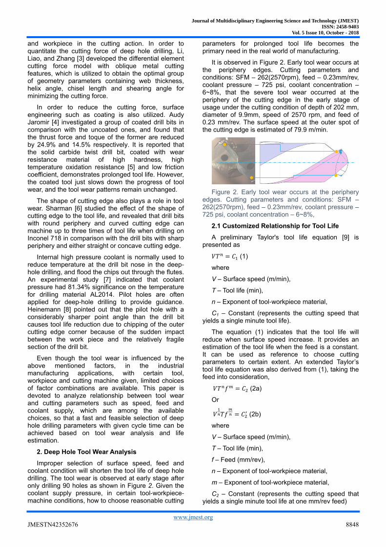
It is observed in Figure 2. Early tool wear occurs at the periphery edges. Cutting parameters and conditions: SFM – 262(2570rpm), feed – 0.23mm/rev, coolant pressure – 725 psi, coolant concentration – 6~8%, that the severe tool wear occurred at the periphery of the cutting edge in the early stage of usage under the cutting condition of depth of 202 mm, diameter of 9.9mm, speed of 2570 rpm, and feed of 0.23 mm/rev. The surface speed at the outer spot of the cutting edge is estimated of 79.9 m/min.
Figure 2. Early tool wear occurs at the periphery edges. Cutting parameters and conditions: SFM – 262(2570rpm), feed – 0.23mm/rev, coolant pressure – 725 psi, coolant concentration – 6~8%,
2.1 Customized Relationship for Tool Life
A preliminary Taylor's tool life equation [9] is presented as
𝑉𝑇𝑛 = 𝐶1 (1)
where
V – Surface speed (m/min),
T – Tool life (min),
n – Exponent of tool-workpiece material,
C1 – Constant (represents the cutting speed that yields a single minute tool life).
The equation (1) indicates that the tool life will reduce when surface speed increase. It provides an estimation of the tool life when the feed is a constant. It can be used as reference to choose cutting parameters to certain extent. An extended Taylor’s tool life equation was also derived from (1), taking the feed into consideration,
𝑉𝑇𝑛𝑓𝑚 = 𝐶2 (2a)
Or
𝑉
𝑇𝑓
= 𝐶2′ (2b)
where
V – Surface speed (m/min),
T – Tool life (min),
f – Feed (mm/rev),
n – Exponent of tool-workpiece material,
m – Exponent of tool-workpiece material,
C2 – Constant (represents the cutting speed that yields a single minute tool life at one mm/rev feed)
Journal of Multidisciplinary Engineering Science and Technology (JMEST)
ISSN: 2458-9403
Vol. 5 Issue 10, October - 2018
www.jmest.org
JMESTN42352676 8849
𝐶2′ - Constant
The exponents on V and f in equation (2b) reflect their contributions to the tool life.
In a more general form [10], Taylor’s tool life equation includes the depth of the cut,
𝑉𝑇𝑛𝑓𝑚𝐷𝑘 = 𝐶3 (3)
where
V – Surface speed (m/min),
T – Tool life (min),
f – Feed (mm/rev),
D – Depth of Cut (mm),
n – Exponent of tool-workpiece material,
m – Exponent of tool-workpiece material,
k – Exponent of tool-workpiece material,
C3 – Constant (represents the cutting speed that yields a single minute tool life, one mm/rev feed, and one mm depth of cut).
It is noteworthy that the Taylor’s tool life equations are derived from the general orthogonal cutting. In the drilling, depth of cut could be simply seen as the radius of the drill bit, which is a constant for a specific drill bit. It makes the equation (3) degrade to equation (2). Since the hole depth significantly influence the cutting temperature [11] and tool life [2], it is reasonable to customize the Taylor’s tool life equation by introducing the hole depth into consideration, i.e.,
𝑉𝑇𝑛𝑓𝑚𝐿𝑘 = 𝐶𝑑𝑟𝑖𝑙 (4)
where
V – Surface speed (m/min),
T – Tool life (min),
f – Feed (mm/rev),
L – Depth of hole (mm),
n – Exponent of tool-workpiece material,
m – Exponent of tool-workpiece material,
k – Exponent of tool-workpiece material,
Cdrill – Constant (represents the cutting speed that yields a single minute tool life, one mm/rev feed, and one mm depth of drilling).
The customized equation (4) reflects the effects from the speed, feed and the depth of drilling on tool life. Equation (4) is a generalized case. Given a constant depth of hole, equation (4) degrades to equation (2). Rewrite it in the form,
𝑇 = √𝐶2 𝑉𝑓𝑚⁄
(5)
To maximize the T, it requires that
(𝑉0, 𝑓0) = min {V ∙ 𝑓𝑚}(6)
Meanwhile, the selection of speed and feed are constrained by the cycle time requirement in industrial applications. In this case, the drilling process needs to be completed in 𝑡𝑐𝑦𝑐𝑙𝑒 minutes,
𝑡𝑐𝑦𝑐𝑙𝑒 = 𝜋𝐿𝑑/(1000𝑓𝑉) (7)
where
d – diameter of the drill bit.
Due to the long length of the drill bit, it is not desirable to apply too much torque and thrust on the tool. Excess torque and thrust force applied to the drill bit could result in breakage and buckling of the tool, respectively. Since the torque and thrust force are positively correlated to the feed [12], an upper limit should be set for the feed selection. Temperature at drill bit tip is positively correlated to both speed and feed [13], which will speed up the tool wear, so an upper limit of the speed should be set as well.
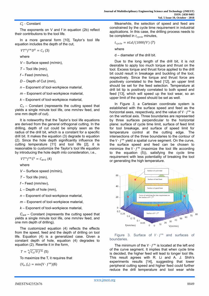
In Figure 3, a Cartesian coordinate system is established with the surface speed and feed as the
horizontal axes, respectively, and the value of V ∙ 𝑓𝑚 is on the vertical axis. Three boundaries are represented by three surfaces perpendicular to the horizontal plane: surface of cycle time limit, surface of feed limit for tool breakage, and surface of speed limit for temperature control at the cutting edge. The intersections of the three boundaries to the contour of the V ∙ 𝑓𝑚 yield a spatial curve segment. On the curve, the surface speed and feed can be chosen to minimize the V ∙ 𝑓𝑚 (maximize the tool life according to the equation (5)), satisfying the cycle time requirement with less potentiality of breaking the tool or generating the high temperature.
Figure 3. Surface of 𝑉 ∙ 𝑓𝑚 and surfaces of boundaries.
The minimum of the V ∙ 𝑓𝑚 is located at the left end of the curve segment. It implies that when cycle time is decided, the higher feed will lead to longer tool life. This result agrees with R. Li and A. J. Shih's experiments results [14], suggesting that lower peripheral cutting speed and higher feed could further reduce the drill temperature and tool wear while
Surface of cycle time
Surface of feed limit
Surface of speed limit
Surface of V ∙ 𝑓𝑚
Curve of satisfying the time requirement on
the Surface of V ∙ 𝑓𝑚
Journal of Multidisciplinary Engineering Science and Technology (JMEST)
ISSN: 2458-9403
Vol. 5 Issue 10, October - 2018
www.jmest.org
JMESTN42352676 8850
maintaining the same Material Remove Rate (MRR). The upper limit of feed is set to prevent the deep hole drill bit from tool breakage due to overloading. It can be also observed that slowing down MMR, is another way for additional tool life extension, however, it implies the increment of cycle time.
2.2. Experiment and tool life estimation
The experiment to verify the analysis and the estimation method are based on the deep hole drilling process of 9.9 mm diameter and 202 mm depth (the L/D ratio is more than 20). The tool is solid carbide twist drill bit coated with TiCrN and the workpiece is SAE1045.
In equation (4), m and n are constants determined by the tool-workpiece materials. In this experimental study, the drill bit and the workpiece are specified. These constants in the equation (4) can be obtained by experimental data. Three groups of cutting parameters are selected to machine the holes, and the data of the drilled holes is summarized in Table 1. Cutting parameters and resultsThe cycle time calculated by equation (7) and the tool life calculated by multiplying the cycle time with number of pieces are listed in the table as well.
Table 1. Cutting parameters and results
V (m/min) f (mm/rev) tcycle (min) N (piece) T (min)
79.9 0.23 0.3149 90 30.77 65.3 0.27 0.3563 250 89.08 65.3 0.225 0.4276 500 213.80
Substituting the three groups of V, f and T in the Table 1. Cutting parameters and resultsinto equation (4) yields the solution of constants m, n and C2. The deep hole tool life is expressed as,
𝑇 = √53570𝑡𝑐𝑦𝑐𝑙𝑒𝑓0.4713/(𝜋𝐿𝑑) . (8)
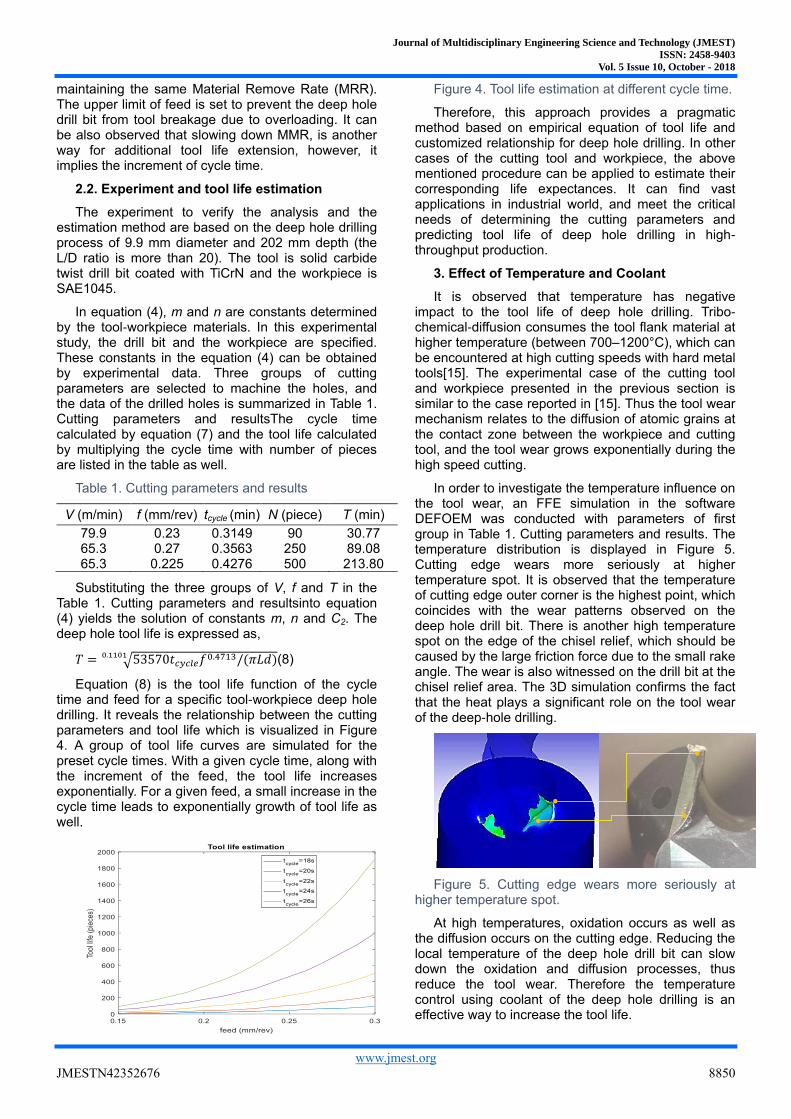
Equation (8) is the tool life function of the cycle time and feed for a specific tool-workpiece deep hole drilling. It reveals the relationship between the cutting parameters and tool life which is visualized in Figure 4. A group of tool life curves are simulated for the preset cycle times. With a given cycle time, along with the increment of the feed, the tool life increases exponentially. For a given feed, a small increase in the cycle time leads to exponentially growth of tool life as well.
Figure 4. Tool life estimation at different cycle time.
Therefore, this approach provides a pragmatic method based on empirical equation of tool life and customized relationship for deep hole drilling. In other cases of the cutting tool and workpiece, the above mentioned procedure can be applied to estimate their corresponding life expectances. It can find vast applications in industrial world, and meet the critical needs of determining the cutting parameters and predicting tool life of deep hole drilling in high-throughput production.
3. Effect of Temperature and Coolant
It is observed that temperature has negative impact to the tool life of deep hole drilling. Tribo-chemical-diffusion consumes the tool flank material at higher temperature (between 700–1200°C), which can be encountered at high cutting speeds with hard metal tools[15]. The experimental case of the cutting tool and workpiece presented in the previous section is similar to the case reported in [15]. Thus the tool wear mechanism relates to the diffusion of atomic grains at the contact zone between the workpiece and cutting tool, and the tool wear grows exponentially during the high speed cutting.
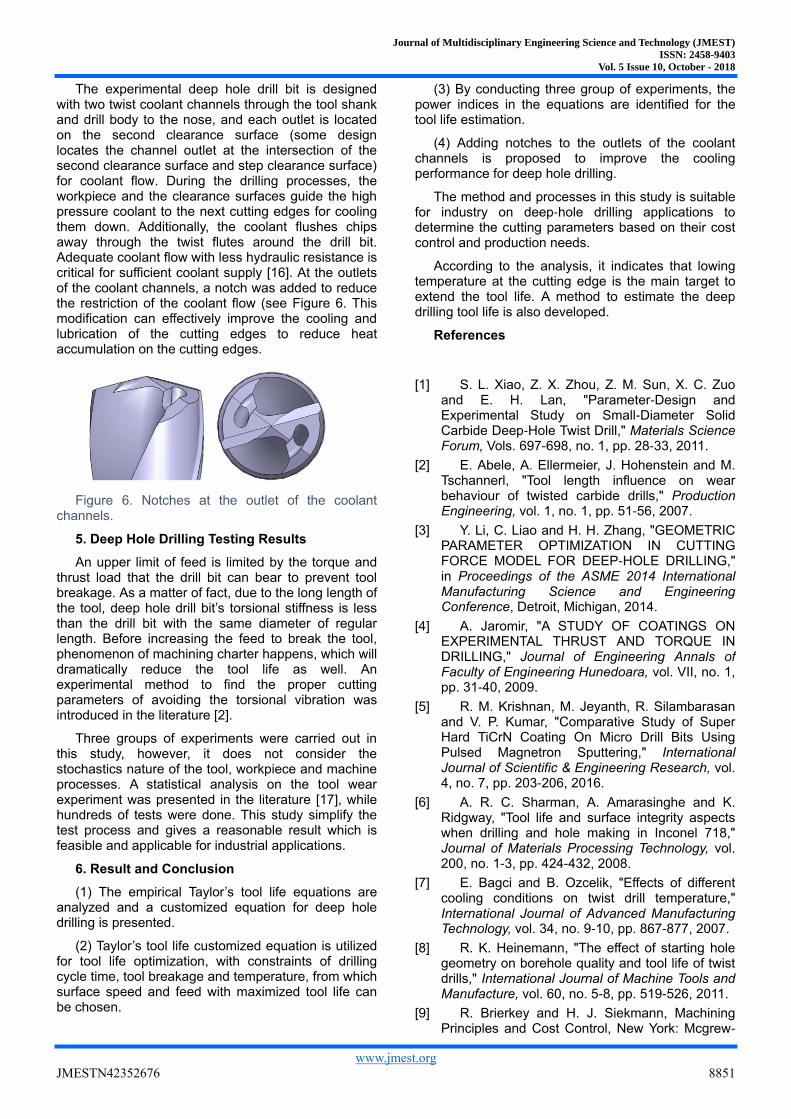
In order to investigate the temperature influence on the tool wear, an FFE simulation in the software DEFOEM was conducted with parameters of first group in Table 1. Cutting parameters and results. The temperature distribution is displayed in Figure 5. Cutting edge wears more seriously at higher temperature spot. It is observed that the temperature of cutting edge outer corner is the highest point, which coincides with the wear patterns observed on the deep hole drill bit. There is another high temperature spot on the edge of the chisel relief, which should be caused by the large friction force due to the small rake angle. The wear is also witnessed on the drill bit at the chisel relief area. The 3D simulation confirms the fact that the heat plays a significant role on the tool wear of the deep-hole drilling.
Figure 5. Cutting edge wears more seriously at higher temperature spot.
At high temperatures, oxidation occurs as well as the diffusion occurs on the cutting edge. Reducing the local temperature of the deep hole drill bit can slow down the oxidation and diffusion processes, thus reduce the tool wear. Therefore the temperature control using coolant of the deep hole drilling is an effective way to increase the tool life.
Journal of Multidisciplinary Engineering Science and Technology (JMEST)
ISSN: 2458-9403
Vol. 5 Issue 10, October - 2018
www.jmest.org
JMESTN42352676 8851
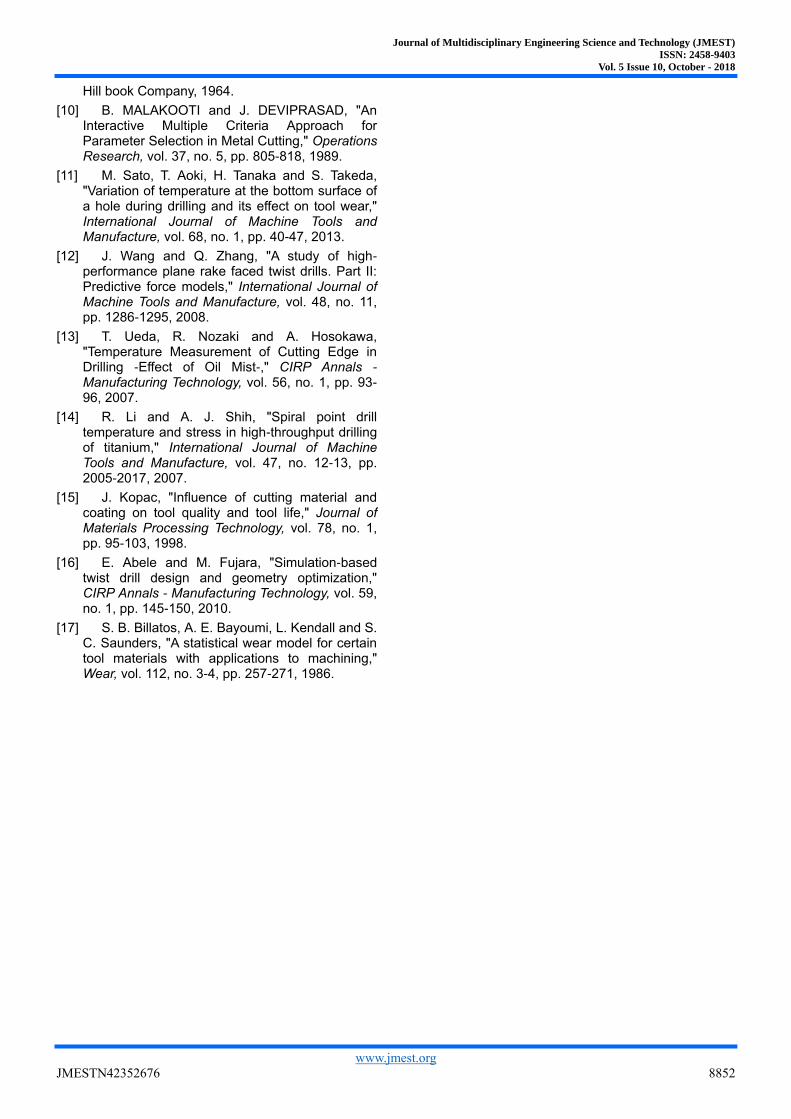
The experimental deep hole drill bit is designed with two twist coolant channels through the tool shank and drill body to the nose, and each outlet is located on the second clearance surface (some design locates the channel outlet at the intersection of the second clearance surface and step clearance surface) for coolant flow. During the drilling processes, the workpiece and the clearance surfaces guide the high pressure coolant to the next cutting edges for cooling them down. Additionally, the coolant flushes chips away through the twist flutes around the drill bit. Adequate coolant flow with less hydraulic resistance is critical for sufficient coolant supply [16]. At the outlets of the coolant channels, a notch was added to reduce the restriction of the coolant flow (see Figure 6. This modification can effectively improve the cooling and lubrication of the cutting edges to reduce heat accumulation on the cutting edges.
Figure 6. Notches at the outlet of the coolant channels.
5. Deep Hole Drilling Testing Results
An upper limit of feed is limited by the torque and thrust load that the drill bit can bear to prevent tool breakage. As a matter of fact, due to the long length of the tool, deep hole drill bit’s torsional stiffness is less than the drill bit with the same diameter of regular length. Before increasing the feed to break the tool, phenomenon of machining charter happens, which will dramatically reduce the tool life as well. An experimental method to find the proper cutting parameters of avoiding the torsional vibration was introduced in the literature [2].
Three groups of experiments were carried out in this study, however, it does not consider the stochastics nature of the tool, workpiece and machine processes. A statistical analysis on the tool wear experiment was presented in the literature [17], while hundreds of tests were done. This study simplify the test process and gives a reasonable result which is feasible and applicable for industrial applications.
6. Result and Conclusion
(1) The empirical Taylor’s tool life equations are analyzed and a customized equation for deep hole drilling is presented.
(2) Taylor’s tool life customized equation is utilized for tool life optimization, with constraints of drilling cycle time, tool breakage and temperature, from which surface speed and feed with maximized tool life can be chosen.
(3) By conducting three group of experiments, the power indices in the equations are identified for the tool life estimation.
(4) Adding notches to the outlets of the coolant channels is proposed to improve the cooling performance for deep hole drilling.
The method and processes in this study is suitable for industry on deep-hole drilling applications to determine the cutting parameters based on their cost control and production needs.
According to the analysis, it indicates that lowing temperature at the cutting edge is the main target to extend the tool life. A method to estimate the deep drilling tool life is also developed.
References
[1] S. L. Xiao, Z. X. Zhou, Z. M. Sun, X. C. Zuo and E. H. Lan, "Parameter-Design and Experimental Study on Small-Diameter Solid Carbide Deep-Hole Twist Drill," Materials Science Forum, Vols. 697-698, no. 1, pp. 28-33, 2011.
[2] E. Abele, A. Ellermeier, J. Hohenstein and M. Tschannerl, "Tool length influence on wear behaviour of twisted carbide drills," Production Engineering, vol. 1, no. 1, pp. 51-56, 2007.
[3] Y. Li, C. Liao and H. H. Zhang, "GEOMETRIC PARAMETER OPTIMIZATION IN CUTTING FORCE MODEL FOR DEEP-HOLE DRILLING," in Proceedings of the ASME 2014 International Manufacturing Science and Engineering Conference, Detroit, Michigan, 2014.
[4] A. Jaromir, "A STUDY OF COATINGS ON EXPERIMENTAL THRUST AND TORQUE IN DRILLING," Journal of Engineering Annals of Faculty of Engineering Hunedoara, vol. VII, no. 1, pp. 31-40, 2009.
[5] R. M. Krishnan, M. Jeyanth, R. Silambarasan and V. P. Kumar, "Comparative Study of Super Hard TiCrN Coating On Micro Drill Bits Using Pulsed Magnetron Sputtering," International Journal of Scientific & Engineering Research, vol. 4, no. 7, pp. 203-206, 2016.
[6] A. R. C. Sharman, A. Amarasinghe and K. Ridgway, "Tool life and surface integrity aspects when drilling and hole making in Inconel 718," Journal of Materials Processing Technology, vol. 200, no. 1-3, pp. 424-432, 2008.
[7] E. Bagci and B. Ozcelik, "Effects of different cooling conditions on twist drill temperature," International Journal of Advanced Manufacturing Technology, vol. 34, no. 9-10, pp. 867-877, 2007.
[8] R. K. Heinemann, "The effect of starting hole geometry on borehole quality and tool life of twist drills," International Journal of Machine Tools and Manufacture, vol. 60, no. 5-8, pp. 519-526, 2011.
[9] R. Brierkey and H. J. Siekmann, Machining Principles and Cost Control, New York: Mcgrew-
Journal of Multidisciplinary Engineering Science and Technology (JMEST)
ISSN: 2458-9403
Vol. 5 Issue 10, October - 2018
www.jmest.org
JMESTN42352676 8852
Hill book Company, 1964.
[10] B. MALAKOOTI and J. DEVIPRASAD, "An Interactive Multiple Criteria Approach for Parameter Selection in Metal Cutting," Operations Research, vol. 37, no. 5, pp. 805-818, 1989.
[11] M. Sato, T. Aoki, H. Tanaka and S. Takeda, "Variation of temperature at the bottom surface of a hole during drilling and its effect on tool wear," International Journal of Machine Tools and Manufacture, vol. 68, no. 1, pp. 40-47, 2013.
[12] J. Wang and Q. Zhang, "A study of high-performance plane rake faced twist drills. Part II: Predictive force models," International Journal of Machine Tools and Manufacture, vol. 48, no. 11, pp. 1286-1295, 2008.
[13] T. Ueda, R. Nozaki and A. Hosokawa, "Temperature Measurement of Cutting Edge in Drilling -Effect of Oil Mist-," CIRP Annals - Manufacturing Technology, vol. 56, no. 1, pp. 93-96, 2007.
[14] R. Li and A. J. Shih, "Spiral point drill temperature and stress in high-throughput drilling of titanium," International Journal of Machine Tools and Manufacture, vol. 47, no. 12-13, pp. 2005-2017, 2007.
[15] J. Kopac, "Influence of cutting material and coating on tool quality and tool life," Journal of Materials Processing Technology, vol. 78, no. 1, pp. 95-103, 1998.
[16] E. Abele and M. Fujara, "Simulation-based twist drill design and geometry optimization," CIRP Annals - Manufacturing Technology, vol. 59, no. 1, pp. 145-150, 2010.
[17] S. B. Billatos, A. E. Bayoumi, L. Kendall and S. C. Saunders, "A statistical wear model for certain tool materials with applications to machining," Wear, vol. 112, no. 3-4, pp. 257-271, 1986.