Embed Size (px)
DESCRIPTION
Selection of Artificial Lift Types
Citation preview
SELECTION OF ARTIFICIAL LIFT SELECTION OF ARTIFICIAL LIFT TYPESTYPES
AP Aung Kyaw
PAB2094
WELL COMPLETION AND
PRODUCTION
Well Completion and Production, PAB 2094
A.P. Aung Kyaw
2
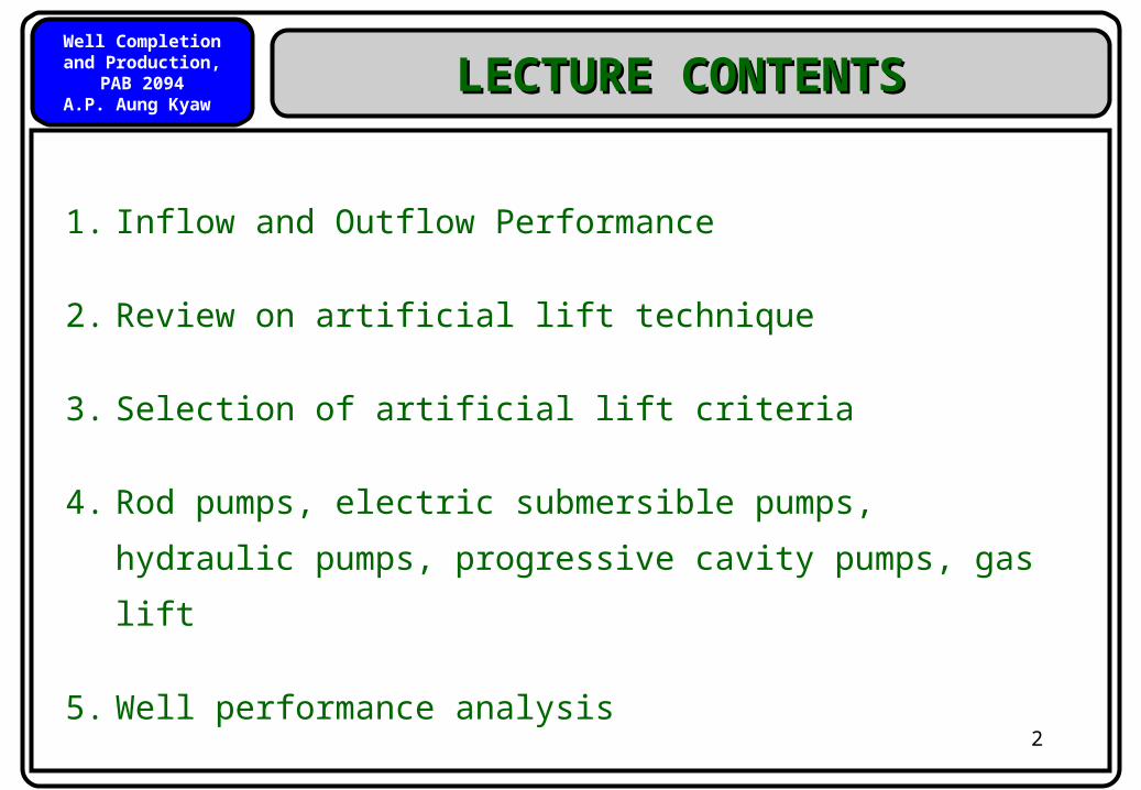
1. Inflow and Outflow Performance
2. Review on artificial lift technique
3. Selection of artificial lift criteria
4. Rod pumps, electric submersible pumps, hydraulic
pumps, progressive cavity pumps, gas lift
5. Well performance analysis
LECTURE CONTENTSLECTURE CONTENTS
Well Completion and Production, PAB 2094
A.P. Aung Kyaw
3
Inflow and Outflow
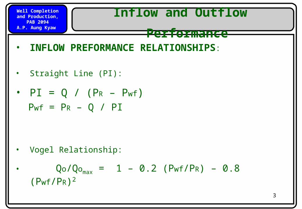
Performance• INFLOW PREFORMANCE RELATIONSHIPS:
• Straight Line (PI):
• PI = Q / (PR – Pwf)Pwf = PR – Q / PI
• Vogel Relationship:
• Qo/Qomax = 1 – 0.2 (Pwf/PR) – 0.8 (Pwf/PR)2
Well Completion and Production, PAB 2094
A.P. Aung Kyaw
4
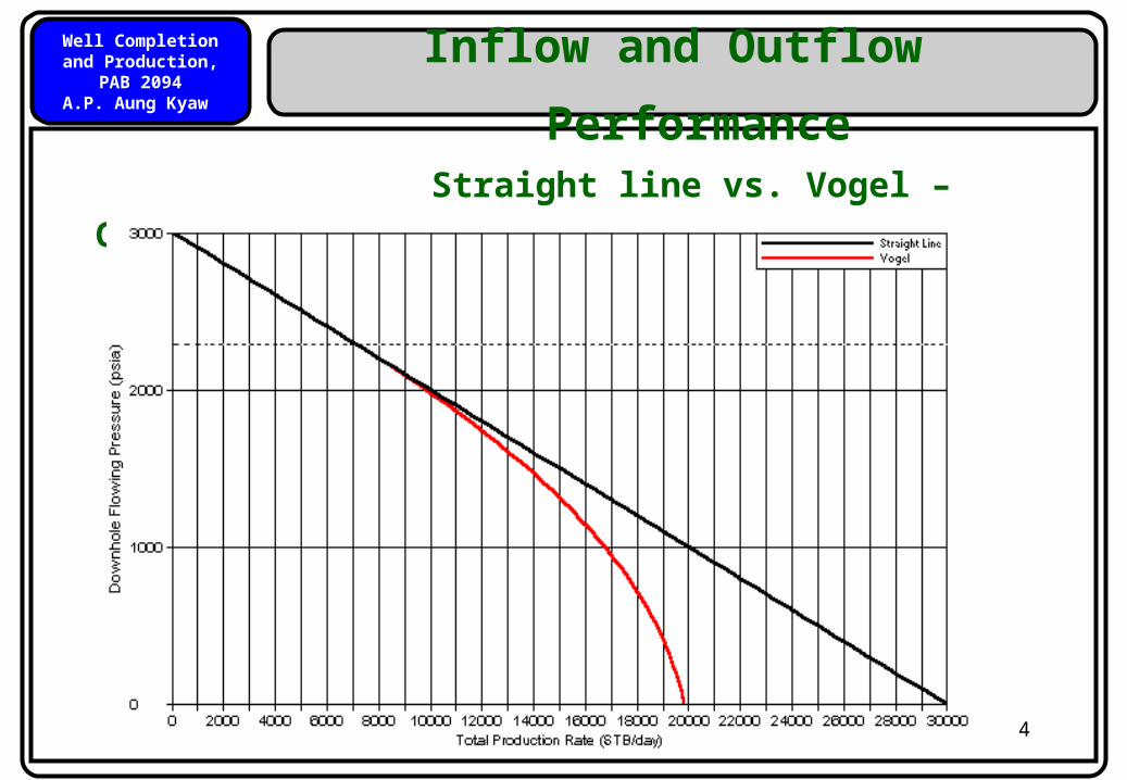
Inflow and Outflow
Performance Straight line vs. Vogel – Graphically
Well Completion and Production, PAB 2094
A.P. Aung Kyaw
5
Inflow and Outflow
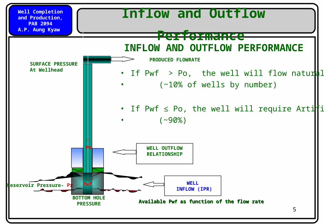
Performance INFLOW AND OUTFLOW PERFORMANCE
SURFACE PRESSUREAt Wellhead
PRODUCED FLOWRATE
WELL OUTFLOWRELATIONSHIP
• If Pwf > Po, the well will flow naturally• (~10% of wells by number)
• If Pwf ≤ Po, the well will require Artificial Lift • (~90%)
Pwf
BOTTOM HOLEPRESSURE
Po
Reservoir Pressure- Pr WELL INFLOW (IPR)
Available PAvailable Pwfwf as function of the flow rate as function of the flow rate
Pwf
Well Completion and Production, PAB 2094
A.P. Aung Kyaw
6
Inflow and Outflow
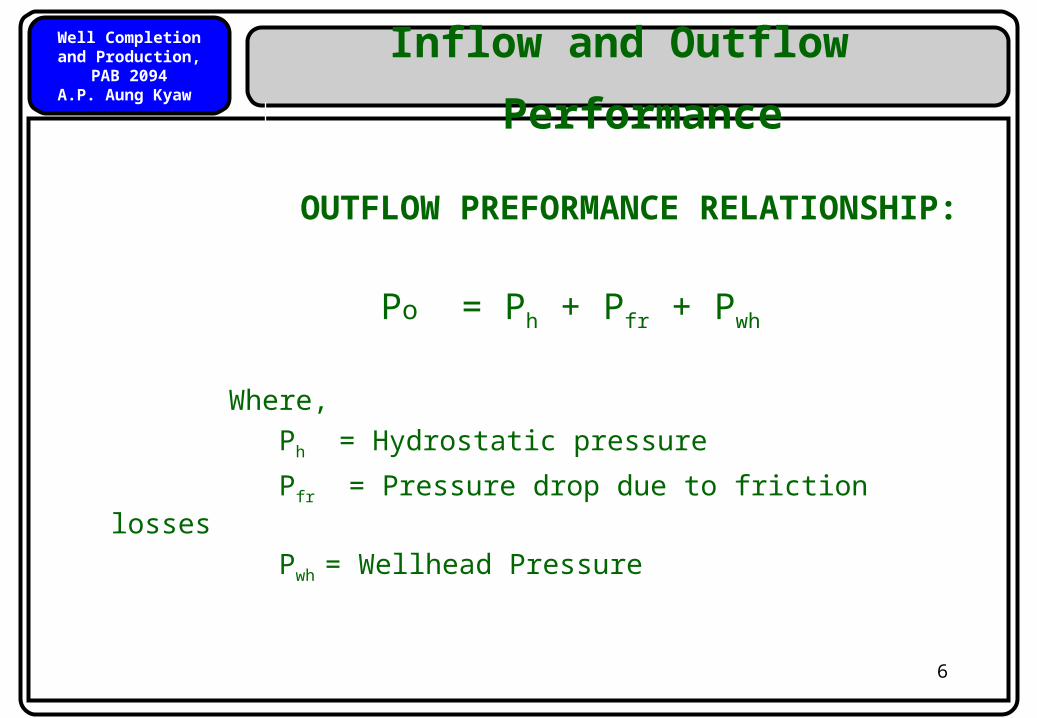
Performance OUTFLOW PREFORMANCE
RELATIONSHIP:
Po = Ph + Pfr + Pwh
Where, Ph = Hydrostatic pressure
Pfr = Pressure drop due to friction losses
Pwh = Wellhead Pressure
Well Completion and Production, PAB 2094
A.P. Aung Kyaw
7
Introduction
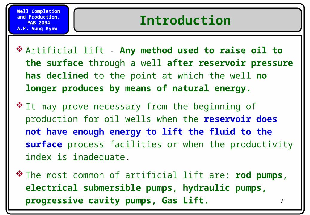
Artificial lift - Any method used to raise oil to the surface
through a well after reservoir pressure has declined to the
point at which the well no longer produces by means of
natural energy.
It may prove necessary from the beginning of production for oil
wells when the reservoir does not have enough energy to
lift the fluid to the surface process facilities or when the
productivity index is inadequate.
The most common of artificial lift are: rod pumps, electrical
submersible pumps, hydraulic pumps, progressive cavity
pumps, Gas Lift.
Well Completion and Production, PAB 2094
A.P. Aung Kyaw
8
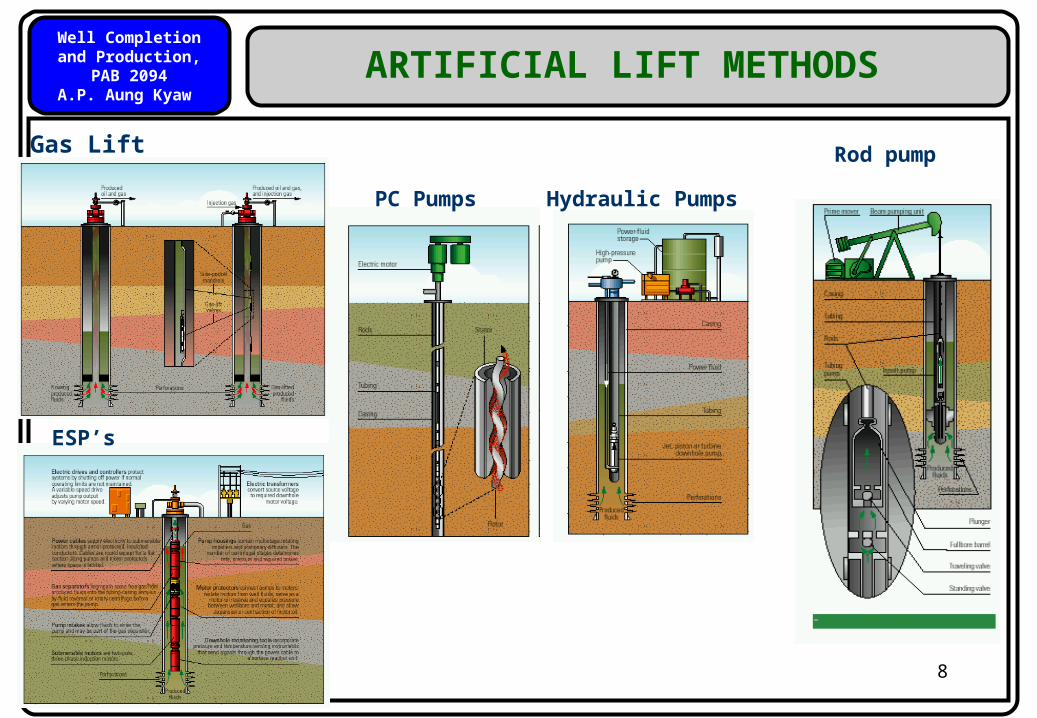
Gas Lift
ESP’s
PC Pumps
Hydraulic Pumps
Rod pump
ARTIFICIAL LIFT METHODS
Well Completion and Production, PAB 2094
A.P. Aung Kyaw
9
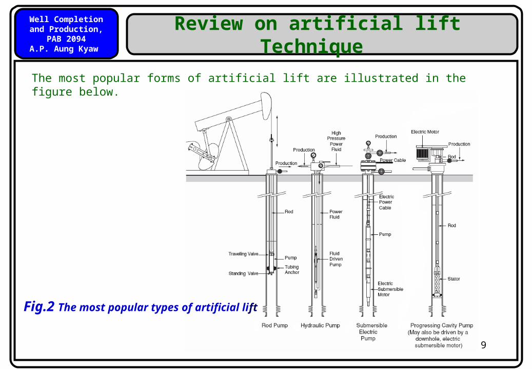
Review on artificial lift Technique
The most popular forms of artificial lift are illustrated in the figure below.
Fig.2 The most popular types of artificial lift
Well Completion and Production, PAB 2094
A.P. Aung Kyaw
10
Review on artificial lift technique
Rod Pump – A down-hole plunger is moved up and down by a rod
connected to an engine at the surface. The plunger movement
displaces produced fluid into the tubing via a pump consisting of
suitably arranged traveling and standing valves mounted within a pump
barrel.
Electric Submersible Pump (ESP) – employs a down-hole
centrifugal pump driven by a three phase, electric motor supplied
with electric power via a cable run from the surface penetrates the
wellhead and is strapped to the outside of the tubing.
Well Completion and Production, PAB 2094
A.P. Aung Kyaw
11
Review on artificial lift technique
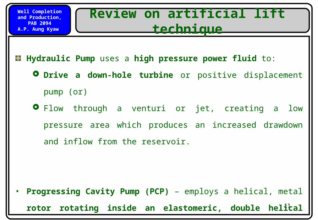
Hydraulic Pump uses a high pressure power fluid to:
Drive a down-hole turbine or positive displacement pump
(or)
Flow through a venturi or jet, creating a low pressure area
which produces an increased drawdown and inflow from the
reservoir.
• Progressing Cavity Pump (PCP) – employs a helical, metal
rotor rotating inside an elastomeric, double helical stator.
The rotating action is supplied by down-hole electric motor or by
rotating rods.
Well Completion and Production, PAB 2094
A.P. Aung Kyaw
12
Selection of artificial Lift
Factors influencing the preferred form of artificial lift –
Well and Reservoir Characteristics
Field Location
Operational Problems
Economics
Implementation on Artificial Lift Selection Techniques
Long Term Reservoir Performance and Facility Constraints
Well Completion and Production, PAB 2094
A.P. Aung Kyaw
13
Rod Pump Pumps
The first type of artificial lift introduced to oil field; most widely used for the following reasons
Low cost
Mechanical simplicity
Easy installation and operation
Rod pumps can lift
o moderate volumes (1000 bfpd) from shallow depths (7,000 ft)
o Small volumes (200 bfpd) from greater depths (14,000 ft)
Well Completion and Production, PAB 2094
A.P. Aung Kyaw
14
Rod Pump Pumps
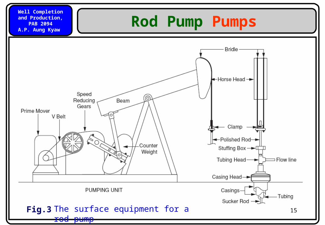
The surface equipment for a rod pump is illustrated in the following figure.
Prime mover – electric motor or gas engine
Gear Reducer – reduces the speed from low torque high rpm to high torque low rpm
Polished rod and sucker rods – connection between pumping unit and down-hole pump.
Polished rod moves up and down through a stuffing box which seals against the polished rod and prevents surface leaks.
Pumping Unit
Well Completion and Production, PAB 2094
A.P. Aung Kyaw
15
Rod Pump Pumps
The surface equipment for a rod pump
Fig.3
Well Completion and Production, PAB 2094
A.P. Aung Kyaw
16
Rod Pump
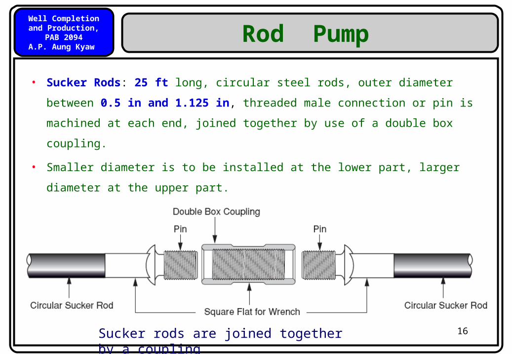
• Sucker Rods: 25 ft long, circular steel rods, outer diameter between
0.5 in and 1.125 in, threaded male connection or pin is machined at
each end, joined together by use of a double box coupling.
• Smaller diameter is to be installed at the lower part, larger diameter
at the upper part.
Sucker rods are joined together by a coupling
Well Completion and Production, PAB 2094
A.P. Aung Kyaw
17
Rod Pump Pumps
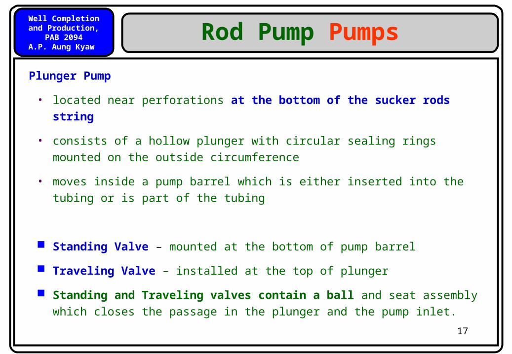
Plunger Pump
• located near perforations at the bottom of the sucker rods string
• consists of a hollow plunger with circular sealing rings mounted on the outside circumference
• moves inside a pump barrel which is either inserted into the tubing or is part of the tubing
Standing Valve – mounted at the bottom of pump barrel
Traveling Valve – installed at the top of plunger
Standing and Traveling valves contain a ball and seat assembly which closes the passage in the plunger and the pump inlet.
Well Completion and Production, PAB 2094
A.P. Aung Kyaw
18
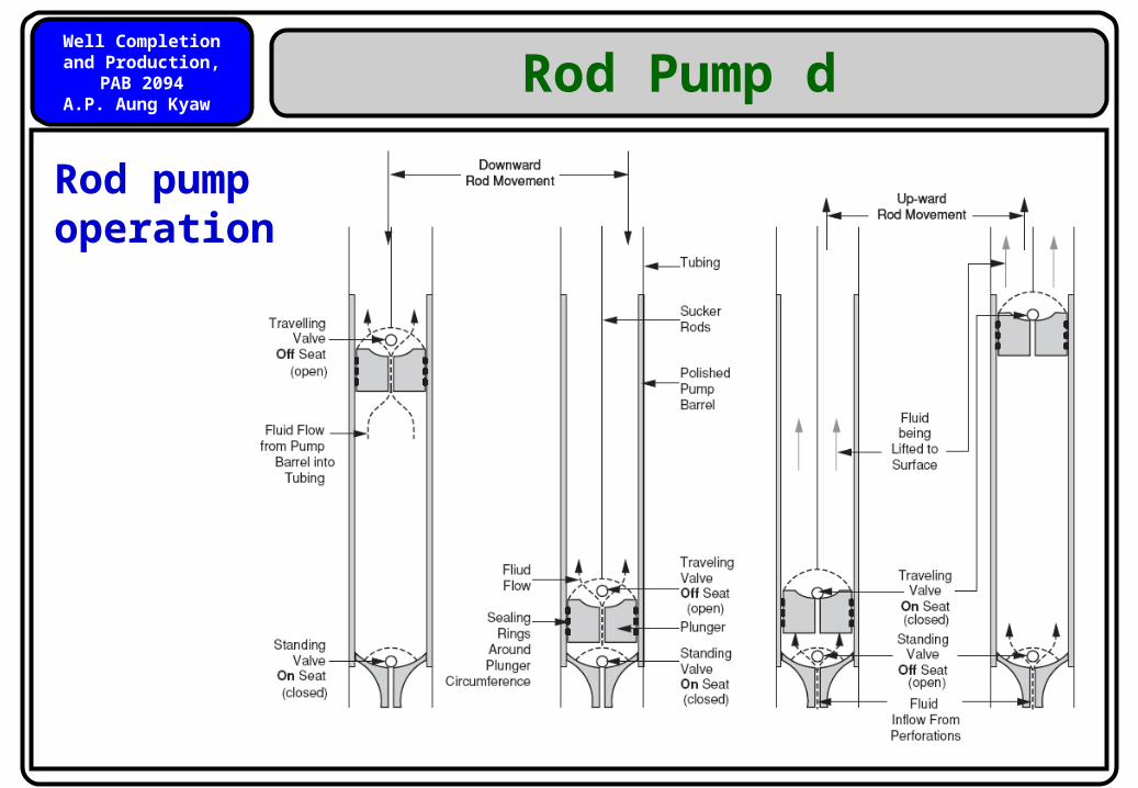
Rod Pump d
Rod pump operation
Well Completion and Production, PAB 2094
A.P. Aung Kyaw
19
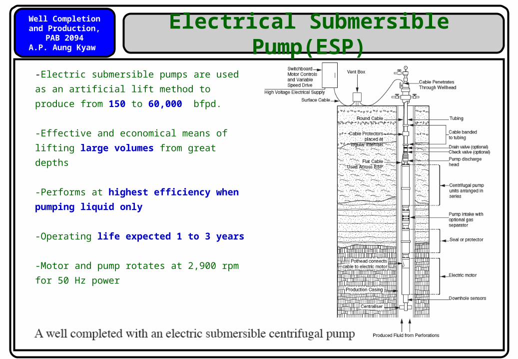
Electrical Submersible Pump(ESP)
-Electric submersible pumps are used as
an artificial lift method to produce from
150 to 60,000 bfpd.
-Effective and economical means of
lifting large volumes from great depths
-Performs at highest efficiency when
pumping liquid only
-Operating life expected 1 to 3 years
-Motor and pump rotates at 2,900 rpm
for 50 Hz power
Well Completion and Production, PAB 2094
A.P. Aung Kyaw
20
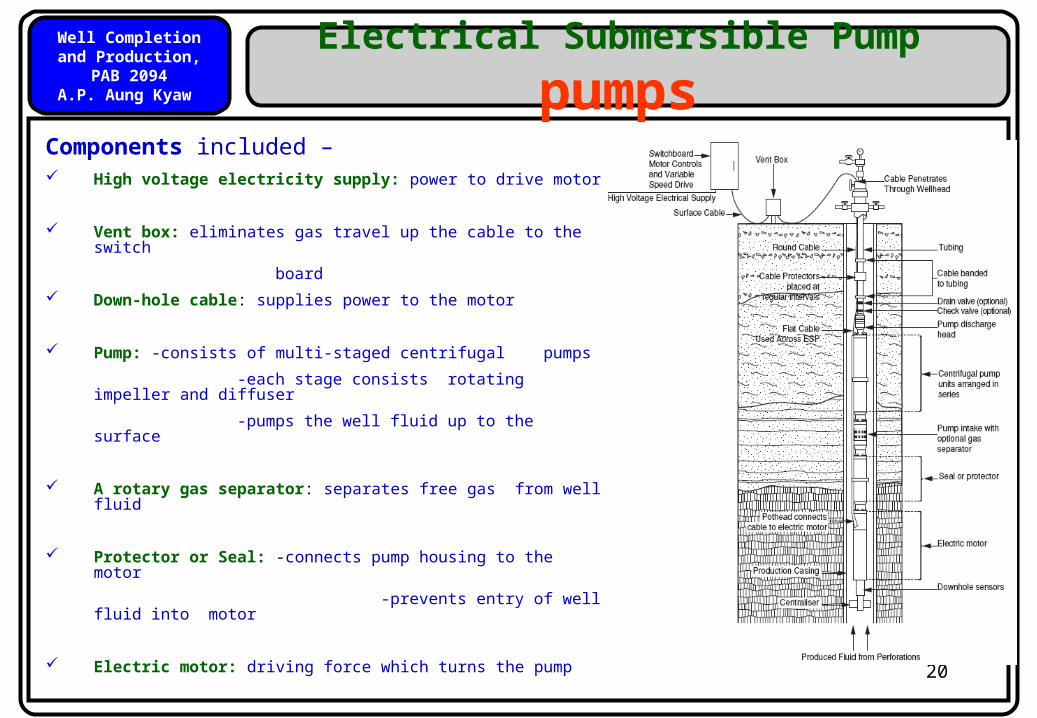
Electrical Submersible Pump
pumpsComponents included – High voltage electricity supply: power to drive motor
Vent box: eliminates gas travel up the cable to the switch
board
Down-hole cable: supplies power to the motor
Pump: -consists of multi-staged centrifugal pumps
-each stage consists rotating impeller and diffuser
-pumps the well fluid up to the surface
A rotary gas separator: separates free gas from well fluid
Protector or Seal: -connects pump housing to the motor
-prevents entry of well fluid into motor
Electric motor: driving force which turns the pump
Well Completion and Production, PAB 2094
A.P. Aung Kyaw
21
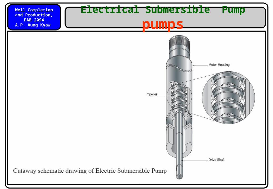
Electrical Submersible Pump
pumps
Well Completion and Production, PAB 2094
A.P. Aung Kyaw
22
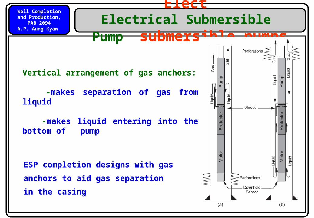
Elect Electrical Submersible Pump
submersible pumps
ESP completion designs with gas
anchors to aid gas separation in the
casing
Vertical arrangement of gas anchors:
-makes separation of gas from liquid
-makes liquid entering into the bottom of pump
Well Completion and Production, PAB 2094
A.P. Aung Kyaw
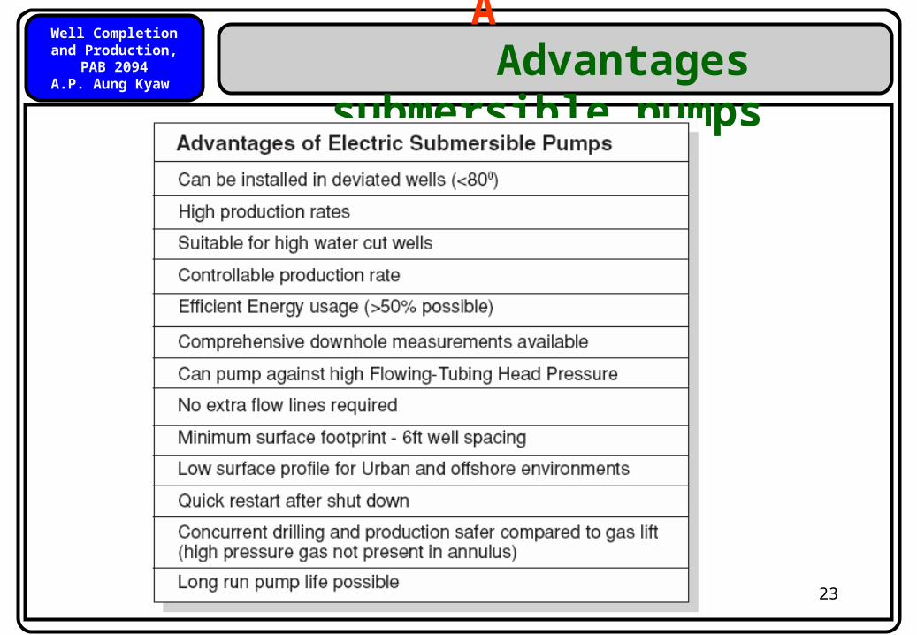
23
A Advantages
submersible pumps
Well Completion and Production, PAB 2094
A.P. Aung Kyaw
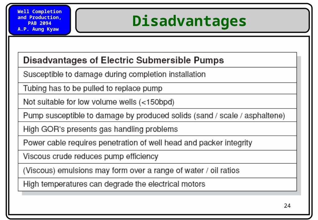
24
Disadvantages
Well Completion and Production, PAB 2094
A.P. Aung Kyaw
25
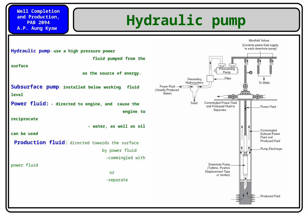
Hydraulic pump
Hydraulic pump: use a high pressure power
fluid pumped from the surface
as the source of energy.
Subsurface pump: installed below working
fluid level
Power fluid: - directed to engine, and cause the
engine to reciprocate
- water, as well as oil can be used
Production fluid: directed towards the surface
by power fluid
-commingled with power fluid
or
-separate
Well Completion and Production, PAB 2094
A.P. Aung Kyaw
26
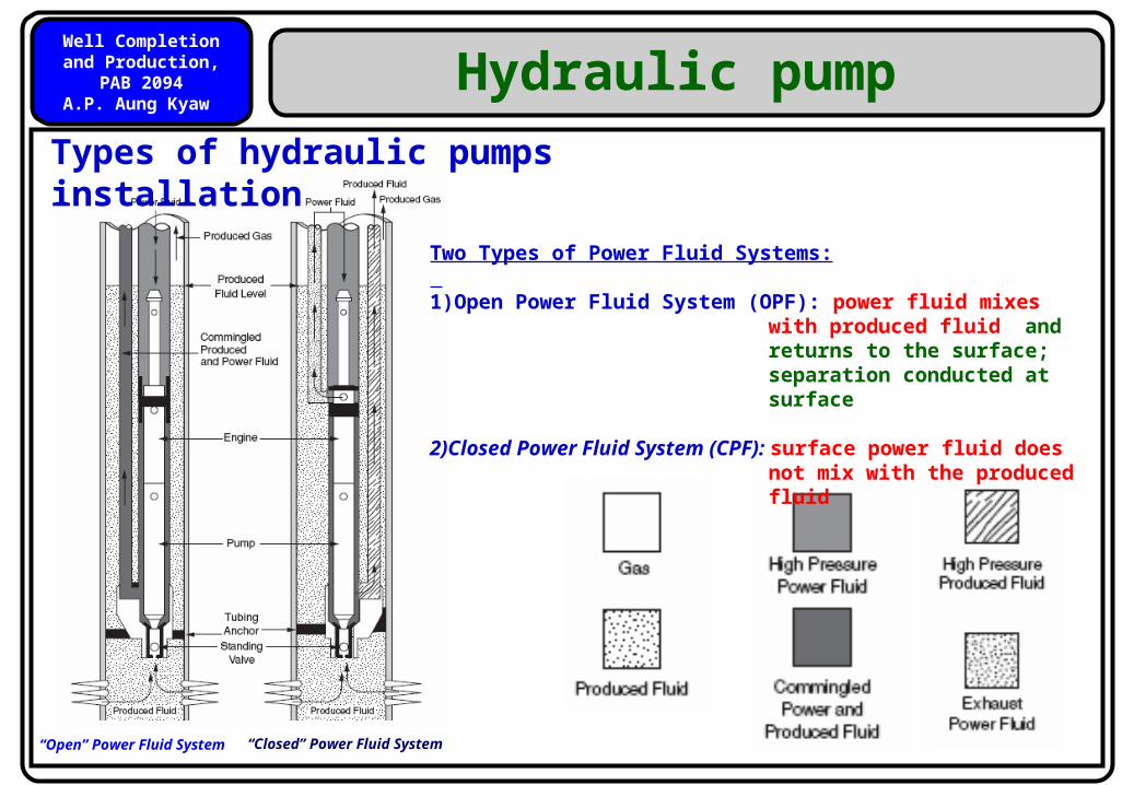
Hydraulic pump
Types of hydraulic pumps installation
“Open” Power Fluid System “Closed” Power Fluid System
Two Types of Power Fluid Systems: 1)Open Power Fluid System (OPF): power fluid mixes with
produced fluid and returns to the surface; separation conducted at surface
2)Closed Power Fluid System (CPF): surface power fluid does not
mix with the produced fluid
Well Completion and Production, PAB 2094
A.P. Aung Kyaw
27
Hydraulic pump
Advantages
Suitable for crooked and deviated wellsCan work at great depths (up to 17,000 ft)Supply of power fluid rate is controllable
No moving parts
Can handle solidsPower source is remote from the wellhead Power fluid can carry corrosion or other inhibitors Pump unit can be easily retrievable by using power fluid in reverse flow
Well Completion and Production, PAB 2094
A.P. Aung Kyaw
28
Hydraulic pump
Disadvantage
A similar volume of power fluid and
produced fluid is required, that is
increasing the size of the production
separators.
Well Completion and Production, PAB 2094
A.P. Aung Kyaw
29
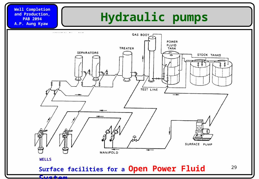
Hydraulic pumps
Wells
Surface facilities for a Open Power Fluid SystemWELLS
Well Completion and Production, PAB 2094
A.P. Aung Kyaw
30
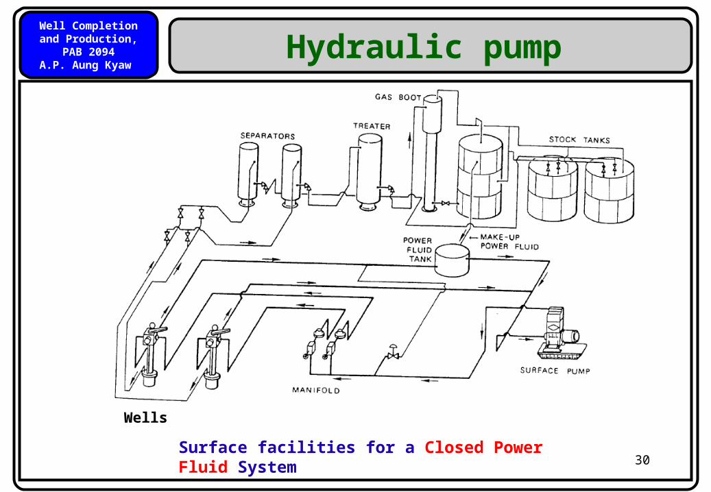
Hydraulic pump
Wells
Surface facilities for a Closed Power Fluid System

Well Completion and Production, PAB 2094
A.P. Aung Kyaw
31
Progressive Cavity Pump(PCP)
1. Used to produce viscous crude oils.
2. Electric motor and gear box mounted on
the surface.
3. Prime mover turns the strings of sucker
rods connected to the Progressing Cavity
Pump.
4. Latest Technology: Tendency of the failure
of tubing and Rods can be reduced by
placing the electric motor down the hole
(known as Progressing Cavity Electric
Submersible Pump, “PCESP”)
A well completed with artificial lift using a progressing cavity pump

Well Completion and Production, PAB 2094
A.P. Aung Kyaw
32
PCP
Progressing Cavity Displacement Pumps
Progressing cavity pumps are based on rotary fluid displacement. This spiral system consists of a rotor turning inside a stationary stator.
Well Completion and Production, PAB 2094
A.P. Aung Kyaw
33
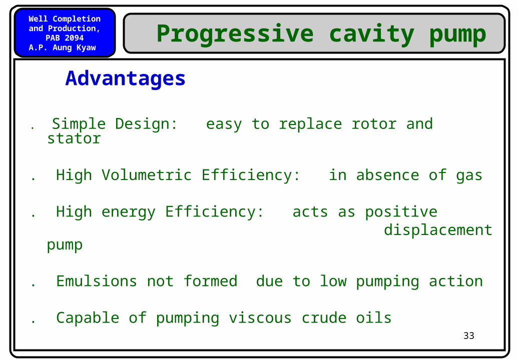
Advantages
. Simple Design: easy to replace rotor and stator
. High Volumetric Efficiency: in absence of gas
. High energy Efficiency: acts as positive displacement pump
. Emulsions not formed due to low pumping action
. Capable of pumping viscous crude oils
Progressive cavity pump
Well Completion and Production, PAB 2094
A.P. Aung Kyaw
34
Progressive cavity pump
Disadvantages
• Elastomers swell in some viscous crude oils
• Problems with rotating rods increase with well depth
Well Completion and Production, PAB 2094
A.P. Aung Kyaw
35
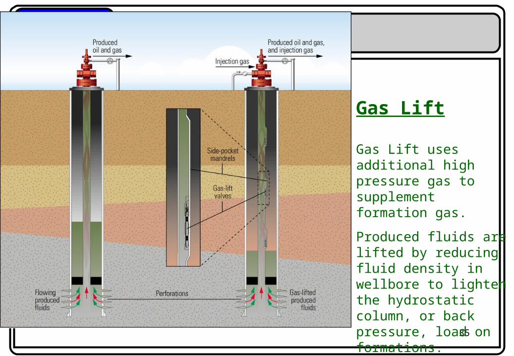
Gas Lift
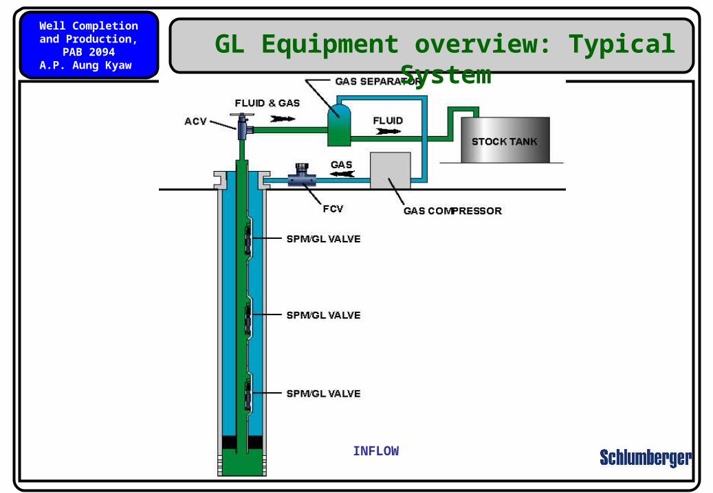
Gas Lift uses additional high pressure gas to supplement formation gas.
Produced fluids are lifted by reducing fluid density in wellbore to lighten the hydrostatic column, or back pressure, load on formations.
Well Completion and Production, PAB 2094
A.P. Aung Kyaw
36
Gas Lift as an Artificial Lift Method
Gas lift injection decreases fluid average density, thus the hydrostatic load on formations is reduced so that available reservoir energy can cause inflow, and commercial hydrocarbon volumes can be boosted or displaced to the surface.
By injecting relatively high pressure gas from the surface to a predetermined depth in the wellbore, the average specific gravity of the fluid decreases which causes a drop in the well face pressure (Pwf) generating additional draw-down which turns on increased fluid production.
Well Completion and Production, PAB 2094
A.P. Aung Kyaw
37INFLOW
GL Equipment overview: Typical System
Well Completion and Production, PAB 2094
A.P. Aung Kyaw
38
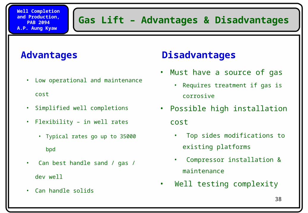
Gas Lift – Advantages & Disadvantages
• Low operational and maintenance
cost
• Simplified well completions
• Flexibility – in well rates
• Typical rates go up to 35000 bpd
• Can best handle sand / gas / dev
well
• Can handle solids
• Must have a source of gas
• Requires treatment if gas is corrosive
• Possible high installation cost
• Top sides modifications to existing
platforms
• Compressor installation &
maintenance
• Well testing complexity
Advantages Disadvantages
Well Completion and Production, PAB 2094
A.P. Aung Kyaw
39
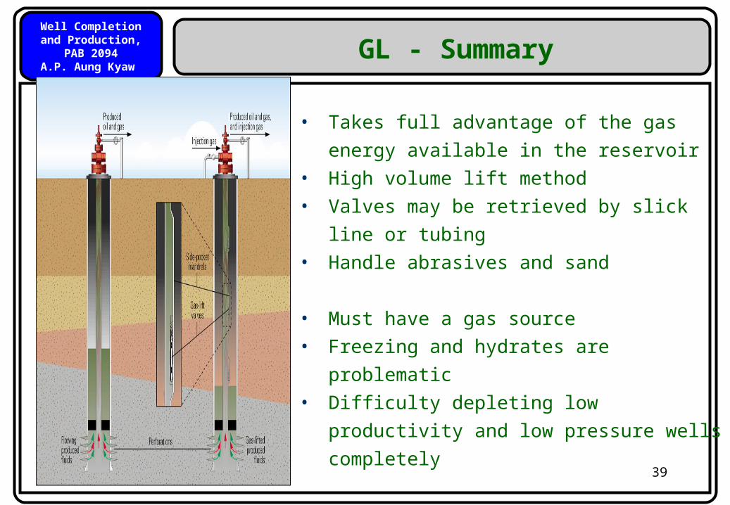
• Takes full advantage of the gas energy
available in the reservoir• High volume lift method• Valves may be retrieved by slick line or
tubing• Handle abrasives and sand
• Must have a gas source• Freezing and hydrates are problematic• Difficulty depleting low productivity and
low pressure wells completely
GL - Summary
Well Completion and Production, PAB 2094
A.P. Aung Kyaw
40
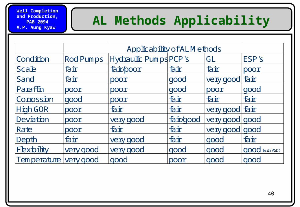
AL Methods Applicability
Condition Rod Pumps Hydraulic PumpsPCP's GL ESP'sScale fair fair/poor fair fair poorSand fair poor good very good fairParaffin poor poor good poor goodCorrossion good poor fair fair fairHigh GOR poor fair fair very good fairDeviation poor very good fair/good very good goodRate poor fair fair very good goodDepth fair very good fair good fairFlexibility very good very good good good good (with VSD)
Temperature very good good poor good good
Applicability of AL Methods

Well Completion and Production, PAB 2094
A.P. Aung Kyaw
41
QUIZ (4)
Write down the operating principle of following artificial lift systems.
(1)(2)