Embed Size (px)
Citation preview
2
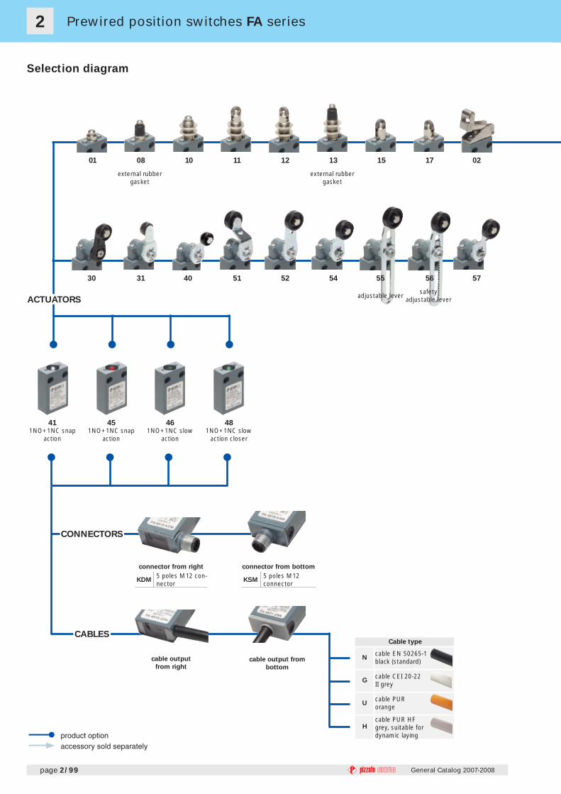
01 08 10 11 12 13 15 17 02
41 45 46 48
30 31 40 51 52 54 55 56 57
page 2/99 General Catalog 2007-2008
Prewired position switches FA series
ACTUATORS
external rubber gasket
external rubber gasket
connector from right
KDM5 poles M12 con-nector
connector from bottom
KSM5 poles M12 connector
CONNECTORS
CABLESCable type
Ncable EN 50265-1 black (standard)
Gcable CEI 20-22 II grey
Ucable PUR orange
Hcable PUR HF grey, suitable for dynamic laying
Selection diagram
adjustable lever safety adjustable lever
cable output
from rightcable output from
bottom
1NO+1NC snap action
1NO+1NC snap action
1NO+1NC slow action
1NO+1NC slow action closer
2
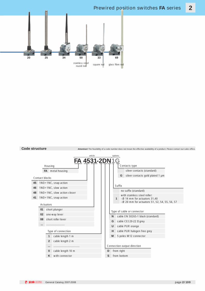
FA 4531-2DN1G
page 2/100General Catalog 2007-2008
Prewired position switches FA series
Contact blocks
45 1NO+1NC, snap action
46 1NO+1NC, slow action
48 1NO+1NC, slow action closer
41 1NO+1NC, snap action
Actuators
01 short plunger
02 one-way lever
08 short roller lever
... ........................
Type of connection
1 cable length 1 m
2 cable length 2 m
... ..................................
0 cable length 10 m
K with connector
Type of cable or connector
N cable EN 50265-1 black (standard)
G cable CEI 20-22 II grey
U cable PUR orange
H cable PUR halogen free grey
M 5 poles M12 connector
Contacts type
silver contacts (standard)
G silver contacts gold plated 1 µm
Housing
FA metal housing
Code structure Attention! The feasibility of a code number does not mean the effective availability of a product. Please contact our sales offi ce.
Suffi x
no suffi x (standard)
1
with stainless steel roller:- Ø 14 mm for actuators 31,40- Ø 20 mm for actuators 51, 52, 54, 55, 56, 57
Connection output direction
D from right
S from bottom
20 25 34 50 33 69
stainless steel round rod square rod glass fi bre rod
article options

2
page 2/101
Technical data
General Catalog 2007-2008
Main data
Metal housing, cable output from right or from bottom
4 integrated cable types available
Versions with M12 connector from right or from bottom suitable for safety applications
Protection degree IP67
4 contact blocks available
24 actuators available
Markings and quality marks:
Approval IMQ: EI007Approval UL: E131787Approval UL: 2007010305229997Approval EZU: 1010151
Electrical data Utilization categories
Alternate current: AC15 (50...60 Hz)Ue (V) 120 250 400Ie (A) 6 4 3Direct current: DC13Ue (V) 24 125 250Ie (A) 2,5 0,55 0,27
Alternate current: AC15 (50...60 Hz)Ue (V) 120 250Ie (A) 4 4Direct current: DC13Ue (V) 24 125 250Ie (A) 2,5 0,55 0,27
Thermal current (Ith): 4 ARated insulation voltage (Ui): 250 VAC 300 VDCProtection against short circuits: fuse 4 A 500 V type gGPollution degree: 3w
ith 5
pol
esM
12 c
onne
ctor
Thermal current (Ith): 10 ARated insulation voltage (Ui): 500 VAC 600 VDCProtection against short circuits: fuse 10 A 500 V type aMPollution degree: 3w
ith c
able
General data
Ambient temperature: See table on page 2/102Max operating frequency: 3600 operations cycles1/hourMechanical endurance: 20 million operations cycles1
Assembling position: anyVibrations holding: 20 gn (10...500 Hz) according to IEC 60068-2-6Shock holding: 50 gn (11 ms) according to IEC 60068-2-27(1) One operation cycle means two movements, one to close and one to open contacts, as foreseen by IEC 947-5-1 standard.
Housing
Metal housing, coated with baked epoxy powderVersion with cable integrated with 5x 0.75 mm2 wires length 2 m, other lengths on request.Versions with 5 poles M12 integrated connector suitable for safety applications Protection degree: IP67
Installation for safety applications:
Use only switches marked with the symbol . The safety circuit must always be connected with the NC contacts (normally closed contacts: see “internal connections” on page 2/102) as stated in the standard EN 60947-5-1, encl. K, par. 2. The switch must be actuated with at least
up to the positive opening travel shown in the travels diagrams on page 6/8. The switch must be actuated at least with the positive opening
force, shown in brackets, underneath each article, near the value of the min. force.
Prewired position switches FA series
In conformity with requirements requested by:
Low Voltage Directive 2006/95/EC, Machinery Directive 2006/42/EC and Electromagnetic Compatibility 2004/108/EC.Positive contact opening in conformity with standards:
IEC 60947-5-1, EN 60947-5-1, VDE 0660-206.
In conformity with standards:
IEC 60947-5-1, EN 60947-5-1, IEC 60204-1, EN 60204-1, EN 1088, EN ISO 12100-1, EN ISO 12100-2, IEC 529, EN 60529, NFC 63-140, VDE 0660-200, VDE 0113, CENELEC EN 50013.Approvals:
IEC 60947-5-1, UL 508, GB14048.5-2001
If not expressly indicated in this chapter, for the right installation and the correct utilization of all articles see requirements indicated
from page 6/1 to page 6/8.

2
10°
page 2/102General Catalog 2007-2008
Please contact our technical service for the list of type approved products.
Please contact our technical service for the list of type approved products.
Data type approved by IMQ and EZU Data type approved by UL
Utilization categories Q300 (69 VA, 125-250 VDC) A600 (720 VA, 120-600 VAC)Data of the housing type 4X, 6 (indoor use only)In conformity with standard: UL 508
Rated insulation voltage (Ui): 500 VAC / 250 VAC (with connector)Thermal current (Ith): 10 A / 4 A (with connector)Protection against short circuits: fuse 10 A 500 V type aMProtection degree: IP67MA terminals (seamed clamps)Pollution degree 3Utilization category: AC15 / DC13 (with connector)Operation voltage (Ue): 400 VAC (50 Hz) / 24 VDC (with connector)Operation current (Ie): 3 A / 2,5 A (with connector)Forms of the contact element: ZbPositive opening of contacts on contact block 45, 46, 48In conformity with standards: EN60947-1, EN 60947-5-1 and subsequent modifi cations and completions, fundamental requirements of the Low Voltage Directive 73/23 EEC and subsequent modifi cations and completions.
According to different versions, it is possible to rotate the head in 90° or 180° steps.
Adjustable levers Overturning levers Rotating heads
It’s possible to fasten the lever on switches on straight or reverse side, maintaining the positive coupling.In this way it is possible to obtain two different work plans of the lever.
In switches with revolving lever it is possi-ble to adjust the lever with 10° steps for the whole 360° range. The positive movement
transmission is always guaran-teed thanks to the particular geo-metrical coupling between the lever and the revolv-ing shaft as pre-scribed for safety applications by the German standard BG-GS-ET-15.
Available on request
Cable code Cable features
Switches FA series standard
versions
Switches FA series extended
temperature versions Approvals of
switches with
integrated cableFixed laying
cableDynamic laying
cable Fixed laying cable Dynamic laying cable
Tmin Tmax Tmin Tmax Tmin Tmax Tmin Tmax
NPVC H05VV-F, fi xed layingNot spreading the fl ame EN 50265-2-1 -25 °C +70 °C - - - - - - CE, IMQ, UL, CCC
GPVC S05VV-F, fi xed layingNot fl ame-spreading CEI 20-22 II -25 °C +70 °C - - - - - - CE
UPolyurethane H05BQ-F, fi xed layingOil-resistant IEC 60811-2-1 -25 °C +70 °C - - -35 °C +80 °C - - CE, IMQ, CCC
H
Polyurethane without halogens, dynamic layingWithout halogens IEC 60754-1Oil-resistant IEC 60811-2-1Self-extinguishing IEC 60332-1, IEC 60332-2Not fl ame-spreading IEC 60332-3Gas emission reduced IEC 61034-1Copper class 6 (IEC 228)
-25 °C +80 °C -25 °C +80 °C -35 °C +80 °C -35 °C +80 °C CE, UL
Available on request
Connector
codeConnector features
Switches FA series standard
versions
Switches FA series extended
temperature versions
Approvals of
switches with
integrated
connectorTmin Tmax Tmin Tmax
K 5 poles M12 connector -25 °C +80 °C -35 °C +80 °C CE, IMQ, UL, CCC
Utilization temperatures and approvals
Internal connections
With cable With M12 connector
BrownBlack
GrayBlue
Yellow-Green
5 poles M12 safety connectors
The long experience of Pizzato Elettrica has lead to the realization of the fi rst 5-poles connector integrated in a safety switch complying with the requirements of standard IEC 947-5-1. Its high insulation voltage Ui 250 VAC allows to mark it as suitable for safety applications
.
Prewired position switches FA series

45 R
46 L
48 LA
41 R
2
45 R
46 L
48 LA
41 R
45 R
46 L
48 LA
41 R
FA 4501-2DN 1NO+1NC
FA 4601-2DN 1NO+1NC
FA 4801-2DN 1NO+1NC
FA 4101-2DN 1NO+1NC
40
20
16
20
Ø 8
4.3
60
Ø 8
30
11.2
40
4.3
20
16
9 21
84
11
44
Ø 8
30
40
20
16
29.8
Ø 7
Ø 11.6
69.8
4.3
Ø 8
30
11.2
16
12 m
ax.
75
Ø 8
3
Ø 8
30
M12x1 17
5124
16
3
86
3.8
12
Ø 8
30
17M12x1
5135
12 m
ax.
16
3.812
3
M12x1
Ø 8
86
30
17
5135
12 m
ax.
1614
max
.88
Ø 7
M12x1
Ø 8
30
3
1751
37
40
20
16
4.3
3.8
30
70
Ø 8
30
11.2
12
40
20
16
4.3
3.8
30
70
Ø 8
30
11.2
12
40
20
16
4.3
Ø 8
30
55
126.
516
6.5
11.2
40
20
16
4.3
7.5
169
129
Ø 8
30
11.2
40
20
16
4.3
19
5.4
18
32.9
54
94
16.1
Ø 8
30
24.8 28
FA 4502-2DN 1NO+1NC
FA 4602-2DN 1NO+1NC
FA 4802-2DN 1NO+1NC
FA 4102-2DN 1NO+1NC
FA 4508-2DN 1NO+1NC
FA 4608-2DN 1NO+1NC
FA 4808-2DN 1NO+1NC
FA 4108-2DN 1NO+1NC
FA 4510-2DN 1NO+1NC
FA 4610-2DN 1NO+1NC
FA 4810-2DN 1NO+1NC
FA 4110-2DN 1NO+1NC
FA 4511-2DN 1NO+1NC
FA 4611-2DN 1NO+1NC
FA 4811-2DN 1NO+1NC
FA 4111-2DN 1NO+1NC
FA 4512-2DN 1NO+1NC
FA 4612-2DN 1NO+1NC
FA 4812-2DN 1NO+1NC
FA 4112-2DN 1NO+1NC
FA 4513-2DN 1NO+1NC
FA 4613-2DN 1NO+1NC
FA 4813-2DN 1NO+1NC
FA 4113-2DN 1NO+1NC
FA 4515-2DN 1NO+1NC
FA 4615-2DN 1NO+1NC
FA 4815-2DN 1NO+1NC
FA 4115-2DN 1NO+1NC
FA 4517-2DN 1NO+1NC
FA 4617-2DN 1NO+1NC
FA 4817-2DN 1NO+1NC
FA 4117-2DN 1NO+1NC
FA 4520-2DN 1NO+1NC
FA 4820-2DN 1NO+1NC
FA 4120-2DN 1NO+1NC
FA 4525-2DN 1NO+1NC
FA 4825-2DN 1NO+1NC
FA 4125-2DN 1NO+1NC
FA 4530-2DN 1NO+1NC
FA 4630-2DN 1NO+1NC
FA 4830-2DN 1NO+1NC
FA 4130-2DN 1NO+1NC
page 2/103
Max speed
Min. force
Travel diagrams
Max speed
Min. force
Travel diagrams
Max speed
Min. force
Travel diagrams
Outline dimensions with cable output from right or from bottom
4830
20 51
4020 4. 3
2040 20
4. 5
4. 3
55. 5
48
General Catalog 2007-2008
Items with code on the green background are available in stock
Prewired position switches FA seriesversions with 2 meter “N” type cable from right
Contacts type:
R = snap actionL = slow action
LA = slow action closer
Contact blocks
Contact blocks
Contact blocks
page 6/7 - type 35 N (25 N )
page 6/8 - group 2
page 6/7 - type 410 N (25 N )
page 6/8 - group 1
page 6/7 - type 410 N (25 N )
page 6/8 - group 1
page 6/7 - type 410 N (25 N )
page 6/8 - group 1
page 6/7 - type 210 N (25 N )
page 6/8 - group 1
page 6/7 - type 210 N (25 N )
page 6/8 - group 1
page 6/7 - type 410 N (25 N )
page 6/8 - group 1
page 6/7 - type 210 N (25 N )
page 6/8 - group 1
page 6/7 - type 210 N (25 N )
page 6/8 - group 1
page 6/7 - type 10,03 Nm (0,25 Nm )
page 6/8 - group 4
With external rubber gasket
With external rubber gasket Fixed only by threaded head
Fixed only by threaded head Fixed only by threaded head Ø 12 mm stainless steel roller
All measures in the drawings are in mm
It does not switch It switches
1 m/s0,07 Nm
page 6/8 - group 3
1 m/s0,07 Nm
page 6/8 - group 3

2
45 R
46 L
48 LA
41 R
45 R
46 L
48 LA
41 R
45 R
46 L
48 LA
41 R
1616
20
19
52
33
14
Ø840
92
30
4.3
28
24.430.2
16
5.5
40
20
16
4.3
19 28
3x3x125
4.5 26.3
38 -
135
78 -
175
Ø 8
30
24.8
40
20
16
4.3
19
28
18.9165
Ø 8
30
Ø 7.3
24.8
55
106
32.9
20
19
14
33
Ø8
30
5240
92 4.3
12
40.1
28
5.5
16
FA 4531-2DN 1NO+1NC
FA 4631-2DN 1NO+1NC
FA 4831-2DN 1NO+1NC
FA 4131-2DN 1NO+1NC
FA 4533-2DN 1NO+1NC
FA 4633-2DN 1NO+1NC
FA 4833-2DN 1NO+1NC
FA 4133-2DN 1NO+1NC
FA 4534-2DN 1NO+1NC
FA 4634-2DN 1NO+1NC
FA 4834-2DN 1NO+1NC
FA 4134-2DN 1NO+1NC
FA 4540-2DN 1NO+1NC
FA 4640-2DN 1NO+1NC
FA 4840-2DN 1NO+1NC
FA 4140-2DN 1NO+1NC
40
20
16
4.3
19
28
Ø3x125
4.5 26.3
38 -
135
78 -
175
Ø 8
30
24.8
40
20
16
4.3
19 28
20
7
99
6.8
45.3
59Ø
8
30
24.8
20
108
68
40
20
16
4.3
19 28
720.3
31.3
Ø 8
30
24.8
40
20
16
4.3
19 28
716.3
35.3
59
99
Ø 8
30
24.8
20
FA 4550-2DN 1NO+1NC
FA 4650-2DN 1NO+1NC
FA 4850-2DN 1NO+1NC
FA 4150-2DN 1NO+1NC
FA 4551-2DN 1NO+1NC
FA 4651-2DN 1NO+1NC
FA 4851-2DN 1NO+1NC
FA 4151-2DN 1NO+1NC
FA 4552-2DN 1NO+1NC
FA 4652-2DN 1NO+1NC
FA 4852-2DN 1NO+1NC
FA 4152-2DN 1NO+1NC
FA 4554-2DN 1NO+1NC
FA 4654-2DN 1NO+1NC
FA 4854-2DN 1NO+1NC
FA 4154-2DN 1NO+1NC
40
20
16
19 28
7
20.3
31.3
53- 1
12
93- 1
52
Ø 8
30
24.8
20
4.3
40
20
16
19
28
7
20.3
31.3
53 -
112
93 -
152
Ø 8
30
24.8
20
4.3
40
20
16
4.3
19
28
Ø 8
30
24.8
20
710.3
41.3
6210
2
40
20
16
4.3
19
28
27.838 -
208
78 -
248
Ø 8
30
24.8
Ø6x200
10
FA 4555-2DN (1) 1NO+1NC
FA 4655-2DN (1) 1NO+1NC
FA 4855-2DN (1) 1NO+1NC
FA 4155-2DN 1NO+1NC
FA 4556-2DN 1NO+1NC
FA 4656-2DN 1NO+1NC
FA 4856-2DN 1NO+1NC
FA 4156-2DN 1NO+1NC
FA 4557-2DN 1NO+1NC
FA 4657-2DN 1NO+1NC
FA 4857-2DN 1NO+1NC
FA 4157-2DN 1NO+1NC
FA 4569-2DN 1NO+1NC
FA 4669-2DN 1NO+1NC
FA 4869-2DN 1NO+1NC
FA 4169-2DN 1NO+1NC
Max speed
Min. force
Travel diagrams
Max speed
Min. force
Travel diagrams
Max speed
Min. force
Travel diagrams
page 2/104
Accessories
Article Description
VF D16 Spacers for FA-FF seriesBy interposing spacers between the switches, it is possible to join two or more prewired switches, prevent-ing them from moving one against the other.10 pcs packs
General Catalog 2007-2008
Prewired position switches FA seriesversions with 2 meter “N” type cable from right
Contacts type:
R = snap actionL = slow action
LA = slow action closer
Contact blocks
Contact blocks
Contact blocks
page 6/7 - type 10,03 Nm (0,25 Nm )
page 6/8 - group 4
1,5 m/s0,03 Nm
page 6/8 - group 4
1,5 m/s0,03 Nm
page 6/8 - group 4
page 6/7 - type 10,03 Nm (0,25 Nm )
page 6/8 - group 4
3x3 mm square rodWith stainless steel roller on request With stainless steel roller on request
With stainless steel roller on requestØ 3 mm stainless steel round rod With stainless steel roller on request With stainless steel roller on request
page 6/7 - type 10,03 Nm (0,25 Nm )
page 6/8 - group 4
page 6/7 - type 10,03 Nm (0,25 Nm )
page 6/8 - group 4
1,5 m/s0,03 Nm
page 6/8 - group 4
page 6/7 - type 10,03 Nm (0,25 Nm )
page 6/8 - group 4
Glass fi bre rodWith stainless steel roller on request With stainless steel roller on request With stainless steel roller on request
1,5 m/s0,03 Nm
page 6/8 - group 4
page 6/7 - type 10,03 Nm (0,25 Nm )
page 6/8 - group 4
page 6/7 - type 10,03 Nm (0,25 Nm )
page 6/8 - group 4
page 6/7 - type 10,03 Nm (0,25 Nm )
page 6/8 - group 4
(1) Positive opening only with lever adjusted on the max. See page 2/51

2
45 R
46 L
48 LA
41 R
45 R
46 L
48 LA
41 R
45 R
46 L
48 LA
41 R
204.3
11.2
41.8
20
44
Ø 8
61.8
M12
x1
14
16
20
4441
,8
219
4,3
44
1430
16
M12
x1
11
85,8
20
29.8
Ø 7
Ø 11.6
4.3
11.2
44
14M12
x1
41.8
71.6
16 16
12 m
ax.
519
Ø 8
3
M12x117
44
14M12
x176.8
2453
12 m
ax.
3
12
17 M12x1
1718
3.8
44
14M12
x1
88
16
3553
16
12
3
M12x1 181712 m
ax.
17
3.8
44
14M12
x1
88
3553
14 m
ax.Ø 7
M 12x1
317
20.4
16.6
44
14M12
x1
90
1653
37
204.3
12
11.2
3.8
44
14M12
x1
41.8
30
71.8
16
20
16
4.3
12
30
11.2
3.8
44
14M12
x1
41.8
71.8
20
16
4.3
55
126.
5
11.2
44
14M12
x1
41.8
168.
3
20
16
4.3
7.5
129
44
14M12
x1
170.
8
41.8
11.2
20
16
4.3
5.4
18
32.916.1
28 19
44
14M12
x1
41.8
5495
.8
FA 4501-KDM 1NO+1NC
FA 4601-KDM 1NO+1NC
FA 4801-KDM 1NO+1NC
FA 4101-KDM 1NO+1NC
FA 4502-KDM 1NO+1NC
FA 4602-KDM 1NO+1NC
FA 4802-KDM 1NO+1NC
FA 4102-KDM 1NO+1NC
FA 4508-KDM 1NO+1NC
FA 4608-KDM 1NO+1NC
FA 4808-KDM 1NO+1NC
FA 4108-KDM 1NO+1NC
FA 4510-KDM 1NO+1NC
FA 4610-KDM 1NO+1NC
FA 4810-KDM 1NO+1NC
FA 4110-KDM 1NO+1NC
FA 4511-KDM 1NO+1NC
FA 4611-KDM 1NO+1NC
FA 4811-KDM 1NO+1NC
FA 4111-KDM 1NO+1NC
FA 4512-KDM 1NO+1NC
FA 4612-KDM 1NO+1NC
FA 4812-KDM 1NO+1NC
FA 4112-KDM 1NO+1NC
FA 4513-KDM 1NO+1NC
FA 4613-KDM 1NO+1NC
FA 4813-KDM 1NO+1NC
FA 4113-KDM 1NO+1NC
FA 4515-KDM 1NO+1NC
FA 4615-KDM 1NO+1NC
FA 4815-KDM 1NO+1NC
FA 4115-KDM 1NO+1NC
FA 4517-KDM 1NO+1NC
FA 4617-KDM 1NO+1NC
FA 4817-KDM 1NO+1NC
FA 4117-KDM 1NO+1NC
FA 4520-KDM 1NO+1NC
FA 4820-KDM 1NO+1NC
FA 4120-KDM 1NO+1NC
FA 4525-KDM 1NO+1NC
FA 4825-KDM 1NO+1NC
FA 4125-KDM 1NO+1NC
FA 4530-KDM 1NO+1NC
FA 4630-KDM 1NO+1NC
FA 4830-KDM 1NO+1NC
FA 4130-KDM 1NO+1NC
page 2/105
Max speed
Min. force
Travel diagrams
Max speed
Min. force
Travel diagrams
Max speed
Min. force
Travel diagrams
Outline dimensions with M12 connector output from right or from bottom
42
20 12
ø 8
16
4. 3
51 60
M12
x1
4020
51
ø 8
60
4013
20
30 16
M12x1
20
4. 3
General Catalog 2007-2008
Items with code on the green background are available in stock
Prewired position switches FA seriesversions with M12 connector from right
Contacts type:
R = snap actionL = slow action
LA = slow action closer
Contact blocks
Contact blocks
Contact blocks
page 6/7 - type 35 N (25 N )
page 6/8 - group 2
page 6/7 - type 410 N (25 N )
page 6/8 - group 1
page 6/7 - type 410 N (25 N )
page 6/8 - group 1
page 6/7 - type 410 N (25 N )
page 6/8 - group 1
page 6/7 - type 210 N (25 N )
page 6/8 - group 1
page 6/7 - type 210 N (25 N )
page 6/8 - group 1
page 6/7 - type 410 N (25 N )
page 6/8 - group 1
page 6/7 - type 210 N (25 N )
page 6/8 - group 1
1 m/s0,07 Nm
page 6/8 - group 3
page 6/7 - type 210 N (25 N )
page 6/8 - group 1
1 m/s0,07 Nm
page 6/8 - group 3
page 6/7 - type 10,03 Nm (0,25 Nm )
page 6/8 - group 4
With external rubber gasket
With external rubber gasket Fixed only by threaded head
Fixed only by threaded head Fixed only by threaded head Ø 12 mm stainless steel roller
Ø 12 mm stainless steel roller
It does not switchIt switches
2
1616
45 R
46 L
48 LA
41 R
45 R
46 L
48 LA
41 R
45 R
46 L
48 LA
41 R
20
33
93.8
14
14
4.3
1952
41.8
44.2
28
24.4
M12x
1
5.5
16
30.2
20
16
4.3
1928
3x3x125
4.526.3
38 -
135
44
14M12
x1
41.8
79.8
- 17
6.8
20
16
4.3
1928
18.3
Ø 7.3
55
106
32.9
44
14M12
x1
41.8
166.
812
5
20
14
14
33
93.8
44.2
1952
41.8
4.3
28
12
40.1
M12
x1
16
5.5
20
16
4.3
1928
Ø3x125
4.526.3
38 -
135
44
14M12
x1
41.8
79.8
- 17
6.8
20
16
4.3
1928
20
7
6.3
45.3
44
14M12
x1
41.8
5910
0.8
20
16
4.3
1928
720
20.3
31.3
44
14M12
x1
41.8
109.
468
20
16
4.3
1928
7
20
16.3
35.3
59
44
14M12
x1
41.8
100.
8
20
16
1928
20
7
20.331.3
53 -
112
4.3
44
14M12
x1
41.8
93.8
- 15
3.8
20
16
1928
20
7
20.331.3
53 -
112
44
14M12
x1
41.8
4.394.8
- 15
3.8
20
16
4.3
1928
20
7 10.3
41.3
44
14M12
x1
41.8
103.
762
20
16
4.3
1928Ø6x200
1027.8
38 -
208
44
14M12
x1
41.8
79.8
- 24
9.8
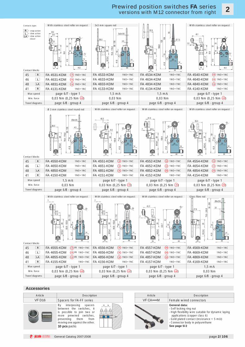
FA 4531-KDM 1NO+1NC
FA 4631-KDM 1NO+1NC
FA 4831-KDM 1NO+1NC
FA 4131-KDM 1NO+1NC
FA 4533-KDM 1NO+1NC
FA 4633-KDM 1NO+1NC
FA 4833-KDM 1NO+1NC
FA 4133-KDM 1NO+1NC
FA 4534-KDM 1NO+1NC
FA 4634-KDM 1NO+1NC
FA 4834-KDM 1NO+1NC
FA 4134-KDM 1NO+1NC
FA 4540-KDM 1NO+1NC
FA 4640-KDM 1NO+1NC
FA 4840-KDM 1NO+1NC
FA 4140-KDM 1NO+1NC
FA 4550-KDM 1NO+1NC
FA 4650-KDM 1NO+1NC
FA 4850-KDM 1NO+1NC
FA 4150-KDM 1NO+1NC
FA 4551-KDM 1NO+1NC
FA 4651-KDM 1NO+1NC
FA 4851-KDM 1NO+1NC
FA 4151-KDM 1NO+1NC
FA 4552-KDM 1NO+1NC
FA 4652-KDM 1NO+1NC
FA 4852-KDM 1NO+1NC
FA 4152-KDM 1NO+1NC
FA 4554-KDM 1NO+1NC
FA 4654-KDM 1NO+1NC
FA 4854-KDM 1NO+1NC
FA 4154-KDM 1NO+1NC
FA 4555-KDM (1) 1NO+1NC
FA 4655-KDM (1) 1NO+1NC
FA 4855-KDM (1) 1NO+1NC
FA 4155-KDM 1NO+1NC
FA 4556-KDM 1NO+1NC
FA 4656-KDM 1NO+1NC
FA 4856-KDM 1NO+1NC
FA 4156-KDM 1NO+1NC
FA 4557-KDM 1NO+1NC
FA 4657-KDM 1NO+1NC
FA 4857-KDM 1NO+1NC
FA 4157-KDM 1NO+1NC
FA 4569-KDM 1NO+1NC
FA 4669-KDM 1NO+1NC
FA 4869-KDM 1NO+1NC
FA 4169-KDM 1NO+1NC
Max speed
Min. force
Travel diagrams
Max speed
Min. force
Travel diagrams
Max speed
Min. force
Travel diagrams
Article Description
VF CA••••M Female wired connectors General data:
- Self locking ring nut- High fl exibility wire suitable for dynamic laying
applications (copper class 6)- Gold plated contact (resistance < 5 mΩ)- Connector body in polyurethaneSee page 5/2
Accessories
Article Description
VF D16 Spacers for FA-FF seriesBy interposing spacers between the switches, it is possible to join two or more prewired switches, preventing them from moving one against the other.10 pcs packs
page 2/106General Catalog 2007-2008
Prewired position switches FA seriesversions with M12 connector from right
Contacts type:
R = snap actionL = slow action
LA = slow action closer
Contact blocks
Contact blocks
Contact blocks
page 6/7 - type 10,03 Nm (0,25 Nm )
page 6/8 - group 4
1,5 m/s0,03 Nm
page 6/8 - group 4
1,5 m/s0,03 Nm
page 6/8 - group 4
page 6/7 - type 10,03 Nm (0,25 Nm )
page 6/8 - group 4
3x3 mm square rodWith stainless steel roller on request With stainless steel roller on request
With stainless steel roller on requestØ 3 mm stainless steel round rod With stainless steel roller on request With stainless steel roller on request
page 6/7 - type 10,03 Nm (0,25 Nm )
page 6/8 - group 4
page 6/7 - type 10,03 Nm (0,25 Nm )
page 6/8 - group 4
1,5 m/s0,03 Nm
page 6/8 - group 4
page 6/7 - type 10,03 Nm (0,25 Nm )
page 6/8 - group 4
Glass fi bre rodWith stainless steel roller on request With stainless steel roller on request With stainless steel roller on request
1,5 m/s0,03 Nm
page 6/8 - group 4
page 6/7 - type 10,03 Nm (0,25 Nm )
page 6/8 - group 4
page 6/7 - type 10,03 Nm (0,25 Nm )
page 6/8 - group 4
page 6/7 - type 10,03 Nm (0,25 Nm )
page 6/8 - group 4