Embed Size (px)
Citation preview
REMEH
A QU
INTA RAN
GE | SELECTIO
N, DESIG
N AN
D INSTALLATIO
N O
F FLUE SYSTEM
S
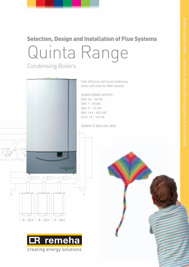
High efficiency wall hung condensingboiler with ultra low NOx emission
QUINTA RANGE OUTPUTSQ30: 5.6 - 28 kWQ45: 7 - 40 kWQ65: 11 - 61 kWQ85: 14.4 - 84.2 kWQ115: 18 - 115 kW
SEDBUK ‘A’ (Q30, Q45, Q65)
Selection, Design and Installation of Flue Systems
Quinta RangeCondensing Boilers
2
Quinta Series flue options The Quinta series of boilers have fan assisted flues and are supplied as standard with a “concentric” flue outlet/air inlet which is used for room sealed operation or for open flue (room ventilated) applications. An optional twin pipe fitting is available for the room sealed “CLV” system The concentric system can be supplied for individual boilers for horizontal or vertical installation and because of the excess fan capacity of the boiler most flue lengths can be accommodated (depending on boiler model and actual route taken) which enables the installer to position the boiler almost anywhere in the building. Open flue or room ventilated systems can be installed as individual or combined flues and should discharge vertically with the flue terminating in a optional tapered cone but c/w bird guard. Care should be taken when siting the actual discharge point as a vapour plume will be visible when the boiler is operating (max flue gas exit temperature will be less than 75°C) and it is possi-ble for water to drip to the ground from the terminal on horizontal installations which could turn to ice in freezing conditions.
Ventilation requirements Compartment Ventilation for Room Sealed Installations Combustion air is not require for the boiler on room sealed installations, however ventilation should befitted in accordance with the latest relevent British StandardsNOTE: Other heat emitting equipment (pipework, pumps etc) may also be in the compartment and must be taken into consideration when deciding on overall ventilation requirements Recommendations Refer to latest relevent British Standards (Ref BS 5440 - 2 : Specification for installation and maintenance of ventilation
for gas appliances not exceeding 70kW) (1st, 2nd and 3rd family gases)(Ref BS 5440 - 1 : Specification for installation of gas appliances to chimneys and for
maintenance of chimneys not exceeding 70kW) (1st, 2nd and 3rd family gases)
(Ref BS 6644 : Specifcation for installation of gas-fired hot water boilers of rated inputs between 70kW to 1.8 kW)(net)( 2nd and 3rd family gases)(Ref IGE/UP/10) Installation of flued gas appliances in industrial and commercial premises.
It is the responsibilty of the installer to install the flue to comply with the current regulations and standards. Note: New type Retro fit plume kits for all the Quinta range are not available at the
time of print For information regarding plume kits please contact our technical department
3
FLUE GAS
AIR IN
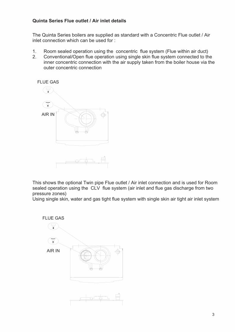
The Quinta Series boilers are supplied as standard with a Concentric Flue outlet / Air inlet connection which can be used for : 1. Room sealed operation using the concentric flue system (Flue within air duct)2. Conventional/Open flue operation using single skin flue system connected to the
inner concentric connection with the air supply taken from the boiler house via the outer concentric connection
FLUE GAS
AIR IN
This shows the optional Twin pipe Flue outlet / Air inlet connection and is used for Room sealed operation using the CLV flue system (air inlet and flue gas discharge from two pressure zones) Using single skin, water and gas tight flue system with single skin air tight air inlet system
Quinta Series Flue outlet / Air inlet details
4
HRS Room sealed terminal (80/125)
150-500
50mm insertion lengthinto mating socket
610745
BS RAL Colour 9016 / 7021
125 o/d
4 x 5mm holes204 Sq
240Sq.
95145
90° Boiler short bend (80/125)
80 o/d
110
QBF0002
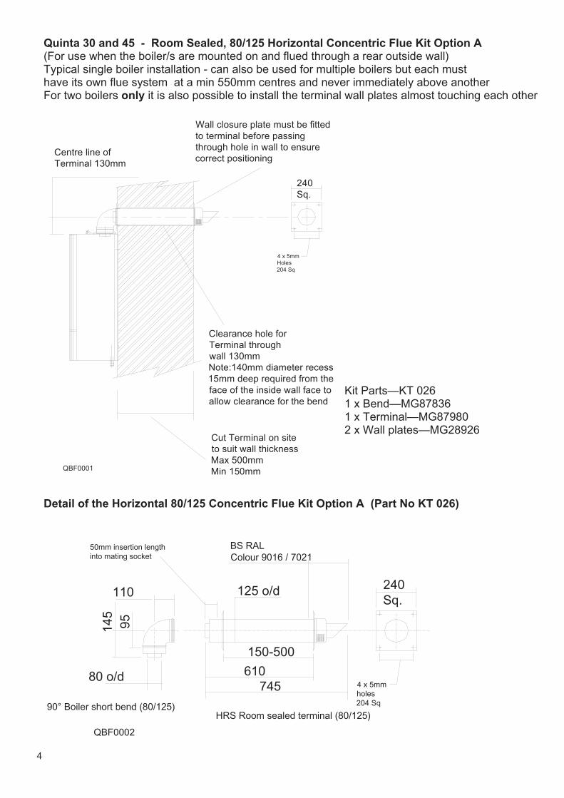
Detail of the Horizontal 80/125 Concentric Flue Kit Option A (Part No KT 026)
Quinta 30 and 45 - Room Sealed, 80/125 Horizontal Concentric Flue Kit Option A (For use when the boiler/s are mounted on and flued through a rear outside wall) Typical single boiler installation - can also be used for multiple boilers but each must have its own flue system at a min 550mm centres and never immediately above anotherFor two boilers only it is also possible to install the terminal wall plates almost touching each other
240Sq.
4 x 5mm Holes204 Sq
Centre line of Terminal 130mm
Clearance hole forTerminal through wall 130mmNote:140mm diameter recess 15mm deep required from the face of the inside wall face to allow clearance for the bend
Cut Terminal on site to suit wall thicknessMax 500mmMin 150mm
Wall closure plate must be fitted to terminal before passing through hole in wall to ensure correct positioning
QBF0001
Kit Parts—KT 026 1 x Bend—MG87836 1 x Terminal—MG87980 2 x Wall plates—MG28926
5
240Sq.
QBF0006
158
80 o/d
208
50
188
90 Bend (80/125) HRS Room sealed terminal (80/125)
150-500
50mm insertion lengthinto mating socket
610745
BS RAL Colour 9016 / 7021
125 o/d
4 x 5mm holes204 Sq
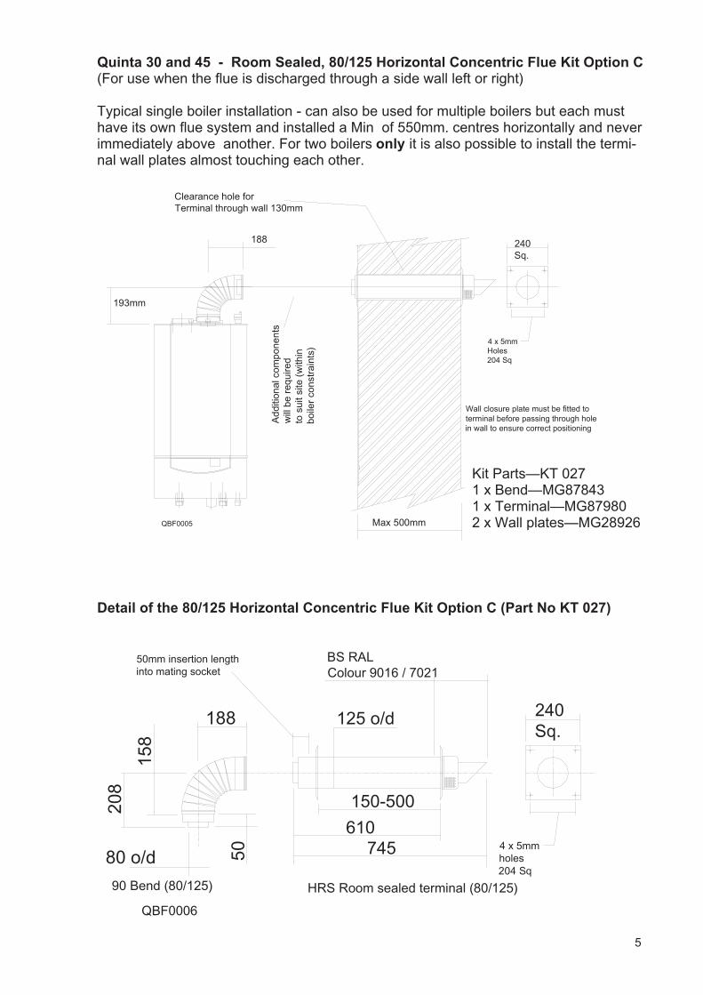
Detail of the 80/125 Horizontal Concentric Flue Kit Option C (Part No KT 027)
Quinta 30 and 45 - Room Sealed, 80/125 Horizontal Concentric Flue Kit Option C (For use when the flue is discharged through a side wall left or right) Typical single boiler installation - can also be used for multiple boilers but each must have its own flue system and installed a Min of 550mm. centres horizontally and never immediately above another. For two boilers only it is also possible to install the termi-nal wall plates almost touching each other.
193mm
Add
ition
al c
ompo
nent
sw
ill b
e r
equi
red
to s
uit s
ite (
with
in
boile
r co
nstr
aint
s)
Clearance hole forTerminal through wall 130mm
188 240Sq.
4 x 5mm Holes204 Sq
Max 500mm
Wall closure plate must be fitted to terminal before passing through hole in wall to ensure correct positioning
QBF0005
Kit Parts—KT 027 1 x Bend—MG87843 1 x Terminal—MG87980 2 x Wall plates—MG28926
6
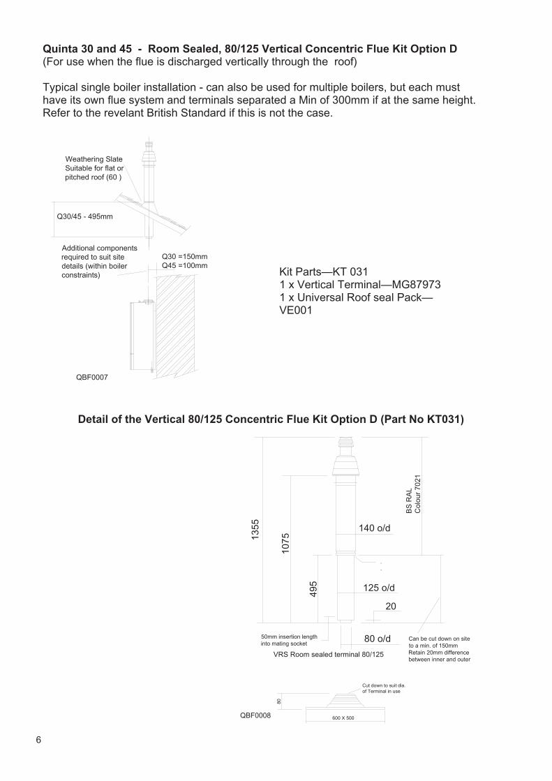
Quinta 30 and 45 - Room Sealed, 80/125 Vertical Concentric Flue Kit Option D (For use when the flue is discharged vertically through the roof) Typical single boiler installation - can also be used for multiple boilers, but each must have its own flue system and terminals separated a Min of 300mm if at the same height.Refer to the revelant British Standard if this is not the case.
QBF0008
VRS Room sealed terminal 80/125
140 o/d
1355
50mm insertion lengthinto mating socket
1075
495
BS
RA
L C
olou
r 70
21
Can be cut down on site to a min. of 150mmRetain 20mm differencebetween inner and outer
.
.
125 o/d
80 o/d
20
600 X 500
Cut down to suit dia. of Terminal in use
80
Detail of the Vertical 80/125 Concentric Flue Kit Option D (Part No KT031)
Kit Parts—KT 031 1 x Vertical Terminal—MG87973 1 x Universal Roof seal Pack— VE001
Q30 =150mmQ45 =100mm
Weathering Slate Suitable for flat or pitched roof (60 )
QBF0007
Q30/45 - 495mm
Additional components required to suit site details (within boiler constraints)
7
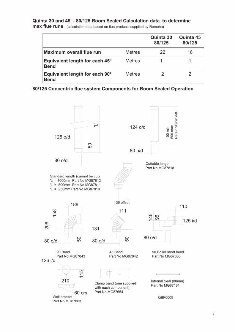
Quinta 30 and 45 - 80/125 Room Sealed Calculation data to determine max flue runs
Quinta 30 80/125
Quinta 45 80/125
Maximum overall flue run Metres 22 16
Equivalent length for each 45° Bend
Metres 1 1
Equivalent length for each 90° Bend
Metres 2 2
80 o/d
125 o/d
'L'
50
80 o/d
124 o/d
110
145
95
80 o/d
125 i/d
80 o/d 50
208
188
80 o/d 50
131
111
90 BendPart No MG87843
45 BendPart No MG87842
90 Boiler short bendPart No MG87836
Cuttable lengthPart No MG87818
Standard length (cannot be cut)'L' = 1000mm Part No MG87812'L' = 500mm Part No MG87811'L' = 250mm Part No MG87810
60 crs
210
126 i/d
Wall bracketPart No MG87863
115
Clamp band (one suppliedwith each component)Part No MG87654
136 offset
158
100
min
500
max
Ret
ain
20m
m d
iff.
Internal Seal (80mm)Part No MG87181
QBF0009
80/125 Concentric flue system Components for Room Sealed Operation
(calculation data based on flue products supplied by Remeha)
8
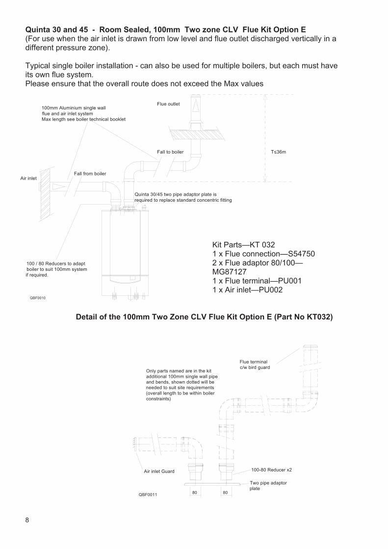
Quinta 30 and 45 - Room Sealed, 100mm Two zone CLV Flue Kit Option E (For use when the air inlet is drawn from low level and flue outlet discharged vertically in a different pressure zone). Typical single boiler installation - can also be used for multiple boilers, but each must have its own flue system.Please ensure that the overall route does not exceed the Max values
Fall to boiler T<36m
Air inletFall from boiler
100 / 80 Reducers to adaptboiler to suit 100mm system
if required.
100mm Aluminium single wall flue and air inlet systemMax length see boiler technical booklet
Flue outlet
Quinta 30/45 two pipe adaptor plate isrequired to replace standard concentric fitting
QBF0010
QBF0011 80
Two pipe adaptor plate
100-80 Reducer x2Air inlet Guard
Flue terminal c/w bird guard
Only parts named are in the kitadditional 100mm single wall pipe and bends, shown dotted will be needed to suit site requirements(overall length to be within boiler constraints)
80
Detail of the 100mm Two Zone CLV Flue Kit Option E (Part No KT032)
Kit Parts—KT 032 1 x Flue connection—S54750 2 x Flue adaptor 80/100— MG87127 1 x Flue terminal—PU001 1 x Air inlet—PU002
9
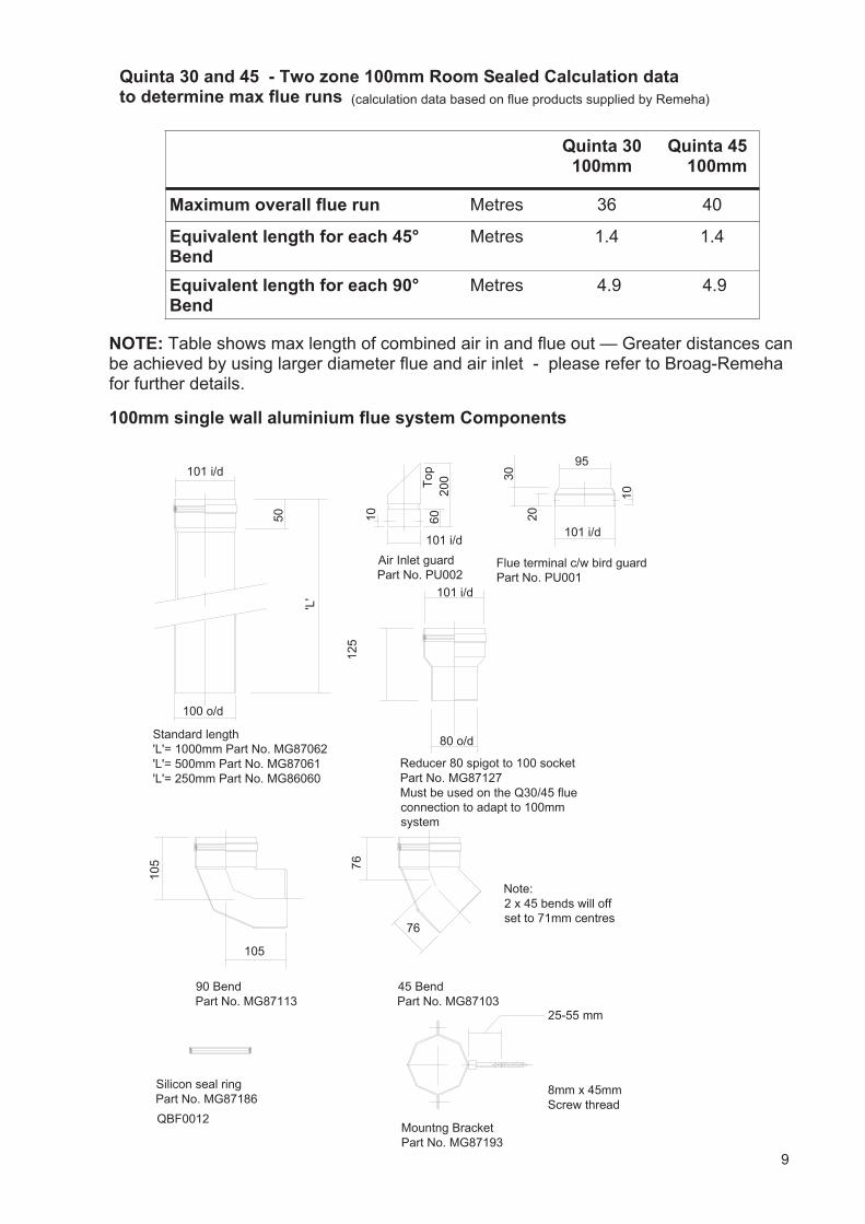
Quinta 30 and 45 - Two zone 100mm Room Sealed Calculation data to determine max flue runs
Quinta 30100mm
Quinta 45 100mm
Maximum overall flue run Metres 36 40
Equivalent length for each 45° Bend
Metres 1.4 1.4
Equivalent length for each 90° Bend
Metres 4.9 4.9
NOTE: Table shows max length of combined air in and flue out — Greater distances can be achieved by using larger diameter flue and air inlet - please refer to Broag-Remehafor further details.
100mm single wall aluminium flue system Components
'L'
101 i/d
100 o/d
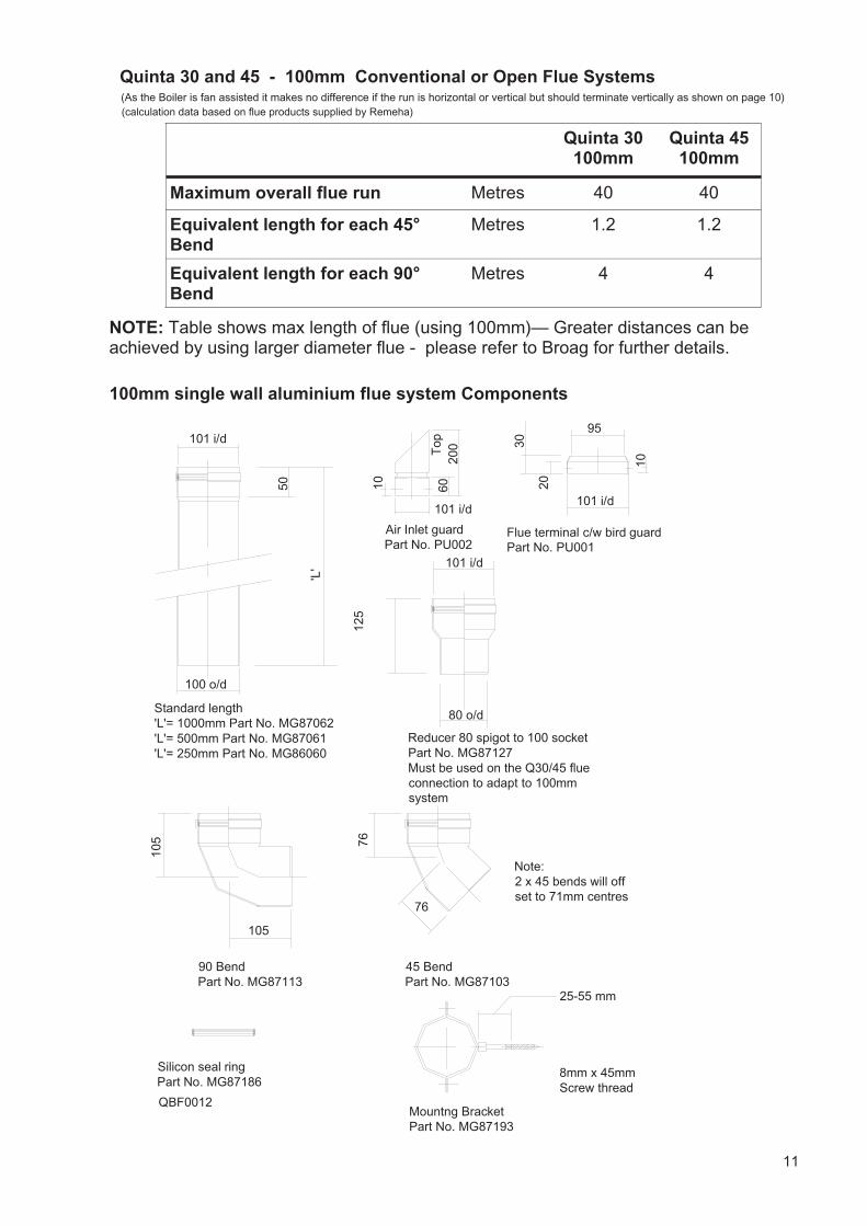
Standard length'L'= 1000mm Part No. MG87062'L'= 500mm Part No. MG87061'L'= 250mm Part No. MG86060
105
105
90 BendPart No. MG87113
45 BendPart No. MG87103
76
76
125
101 i/d
80 o/d
Reducer 80 spigot to 100 socketPart No. MG87127Must be used on the Q30/45 flue connection to adapt to 100mm system
Silicon seal ringPart No. MG87186
50
Mountng BracketPart No. MG87193
8mm x 45mmScrew thread
25-55 mm
Note:2 x 45 bends will off set to 71mm centres
101 i/d
95
30
20
Flue terminal c/w bird guard Part No. PU001
Air Inlet guardPart No. PU002
QBF0012
10
10
200
60
101 i/d
Top
(calculation data based on flue products supplied by Remeha)
10
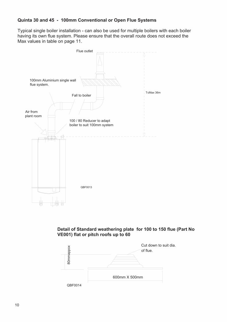
Quinta 30 and 45 - 100mm Conventional or Open Flue Systems Typical single boiler installation - can also be used for multiple boilers with each boiler having its own flue system. Please ensure that the overall route does not exceed the Max values in table on page 11.
Fall to boiler
100 / 80 Reducer to adaptboiler to suit 100mm system
100mm Aluminium single wall flue system.
Flue outlet
QBF0013
Air from plant room
QBF0014
600mm X 500mm
Cut down to suit dia. of flue.
80m
map
pox
Detail of Standard weathering plate for 100 to 150 flue (Part No VE001) flat or pitch roofs up to 60
T<Max 36m
11
Quinta 30 and 45 - 100mm Conventional or Open Flue Systems
Quinta 30 100mm
Quinta 45 100mm
Maximum overall flue run Metres 40 40
Equivalent length for each 45° Bend
Metres 1.2 1.2
Equivalent length for each 90° Bend
Metres 4 4
NOTE: Table shows max length of flue (using 100mm)— Greater distances can be achieved by using larger diameter flue - please refer to Broag for further details.
100mm single wall aluminium flue system Components
'L'
101 i/d
100 o/d
Standard length'L'= 1000mm Part No. MG87062'L'= 500mm Part No. MG87061'L'= 250mm Part No. MG86060
105
105
90 BendPart No. MG87113
45 BendPart No. MG87103
76
76
125
101 i/d
80 o/d
Reducer 80 spigot to 100 socketPart No. MG87127Must be used on the Q30/45 flue connection to adapt to 100mm system
Silicon seal ringPart No. MG87186
50
Mountng BracketPart No. MG87193
8mm x 45mmScrew thread
25-55 mm
Note:2 x 45 bends will off set to 71mm centres
101 i/d
95
30
20Flue terminal c/w bird guard Part No. PU001
Air Inlet guardPart No. PU002
QBF0012
10
10
200
60
101 i/d
Top
(As the Boiler is fan assisted it makes no difference if the run is horizontal or vertical but should terminate vertically as shown on page 10)(calculation data based on flue products supplied by Remeha)
12
QBF0015
DH
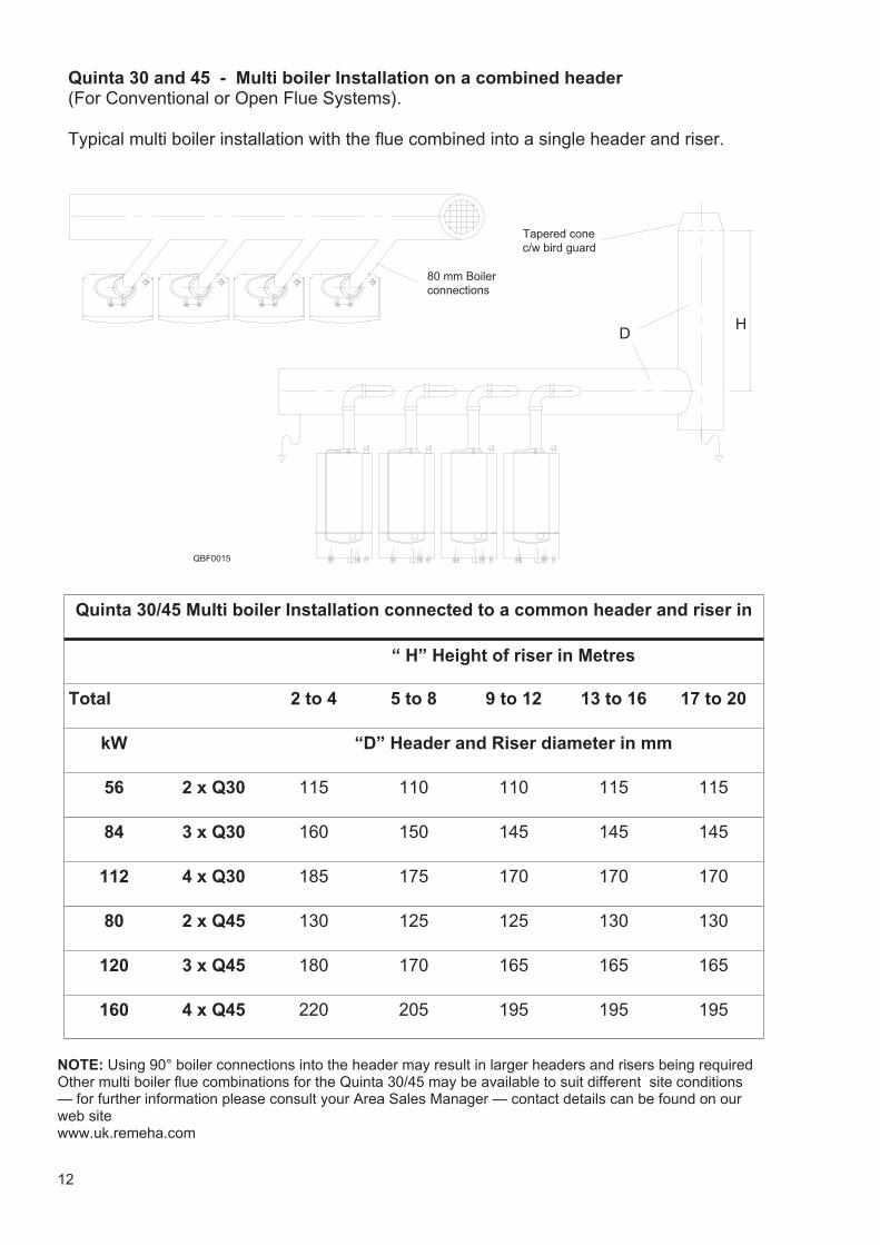
80 mm Boiler connections
Tapered conec/w bird guard
Quinta 30 and 45 - Multi boiler Installation on a combined header (For Conventional or Open Flue Systems). Typical multi boiler installation with the flue combined into a single header and riser.
Quinta 30/45 Multi boiler Installation connected to a common header and riser in
Total 2 to 4 5 to 8 9 to 12 13 to 16 17 to 20
kW “D” Header and Riser diameter in mm
56 2 x Q30 115 110 110 115 115
84 3 x Q30 160 150 145 145 145
112 4 x Q30 185 175 170 170 170
80 2 x Q45 130 125 125 130 130
120 3 x Q45 180 170 165 165 165
160 4 x Q45 220 205 195 195 195
“ H” Height of riser in Metres
NOTE: Using 90° boiler connections into the header may result in larger headers and risers being required Other multi boiler flue combinations for the Quinta 30/45 may be available to suit different site conditions — for further information please consult your Area Sales Manager — contact details can be found on our web site www.uk.remeha.com
13
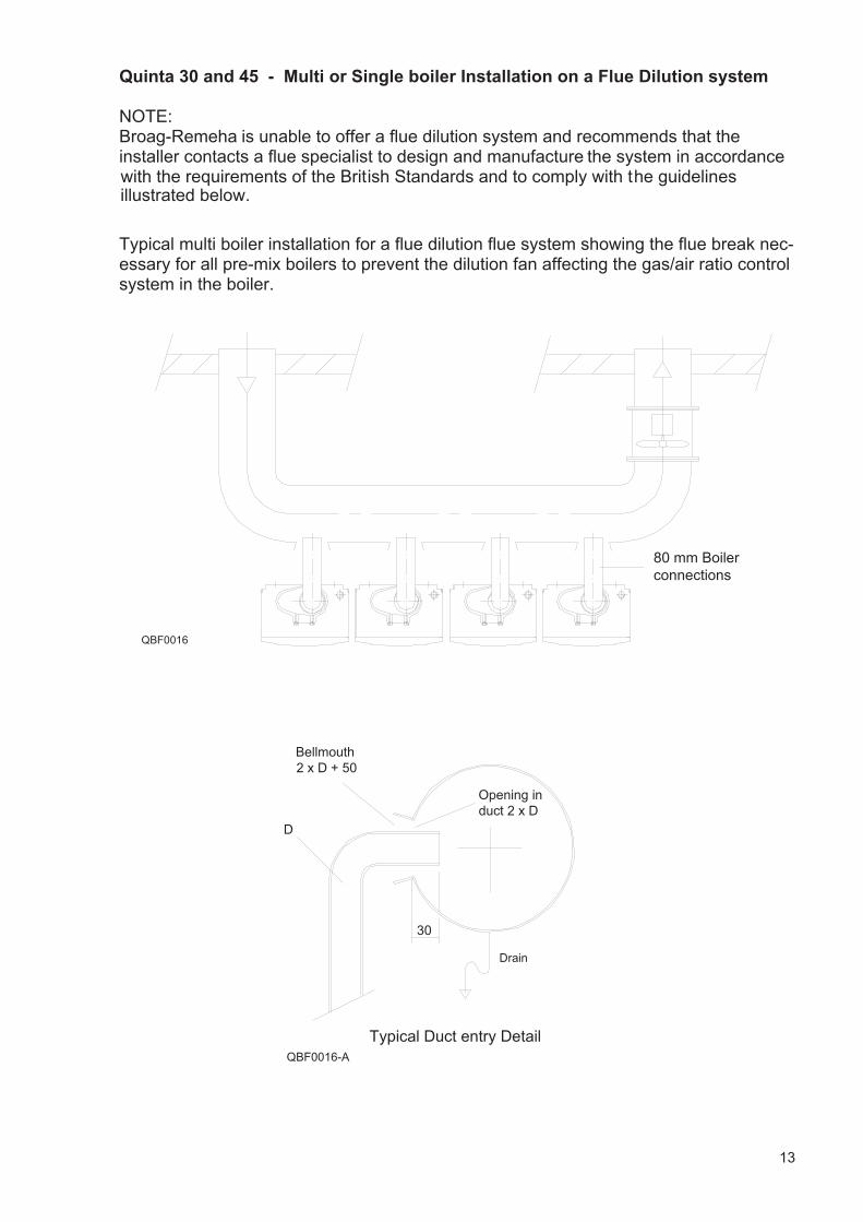
Quinta 30 and 45 - Multi or Single boiler Installation on a Flue Dilution system NOTE: Broag-Remeha is unable to offer a flue dilution system and recommends that theinstaller contacts a flue specialist to design and manufacture the system in accordancewith the requirements of the British Standards and to comply with the guidelines
30
D
Bellmouth2 x D + 50
Opening in duct 2 x D
Typical Duct entry DetailQBF0016-A
Drain
QBF0016
80 mm Boiler connections
Typical multi boiler installation for a flue dilution flue system showing the flue break nec-essary for all pre-mix boilers to prevent the dilution fan affecting the gas/air ratio control system in the boiler.
illustrated below.
14
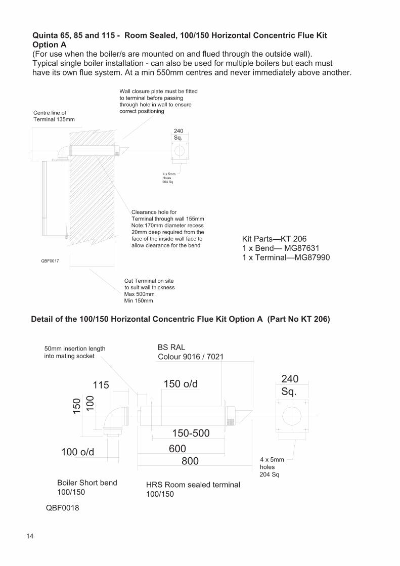
Detail of the 100/150 Horizontal Concentric Flue Kit Option A (Part No KT 206)
4 x 5mm holes204 Sq
150-500
800600
HRS Room sealed terminal 100/150
50mm insertion lengthinto mating socket
Boiler Short bend100/150
QBF0018
115
100 o/d
150
100
240Sq.
BS RAL Colour 9016 / 7021
150 o/d
Quinta 65, 85 and 115 - Room Sealed, 100/150 Horizontal Concentric Flue Kit Option A (For use when the boiler/s are mounted on and flued through the outside wall). Typical single boiler installation - can also be used for multiple boilers but each must have its own flue system. At a min 550mm centres and never immediately above another. Wall closure plate must be fitted
to terminal before passing through hole in wall to ensure correct positioning
QBF0017
Centre line of Terminal 135mm
Clearance hole forTerminal through wall 155mmNote:170mm diameter recess 20mm deep required from the face of the inside wall face to allow clearance for the bend
4 x 5mm Holes204 Sq
240Sq.
Cut Terminal on site to suit wall thicknessMax 500mmMin 150mm
Kit Parts—KT 206 1 x Bend— MG87631 1 x Terminal—MG87990
15
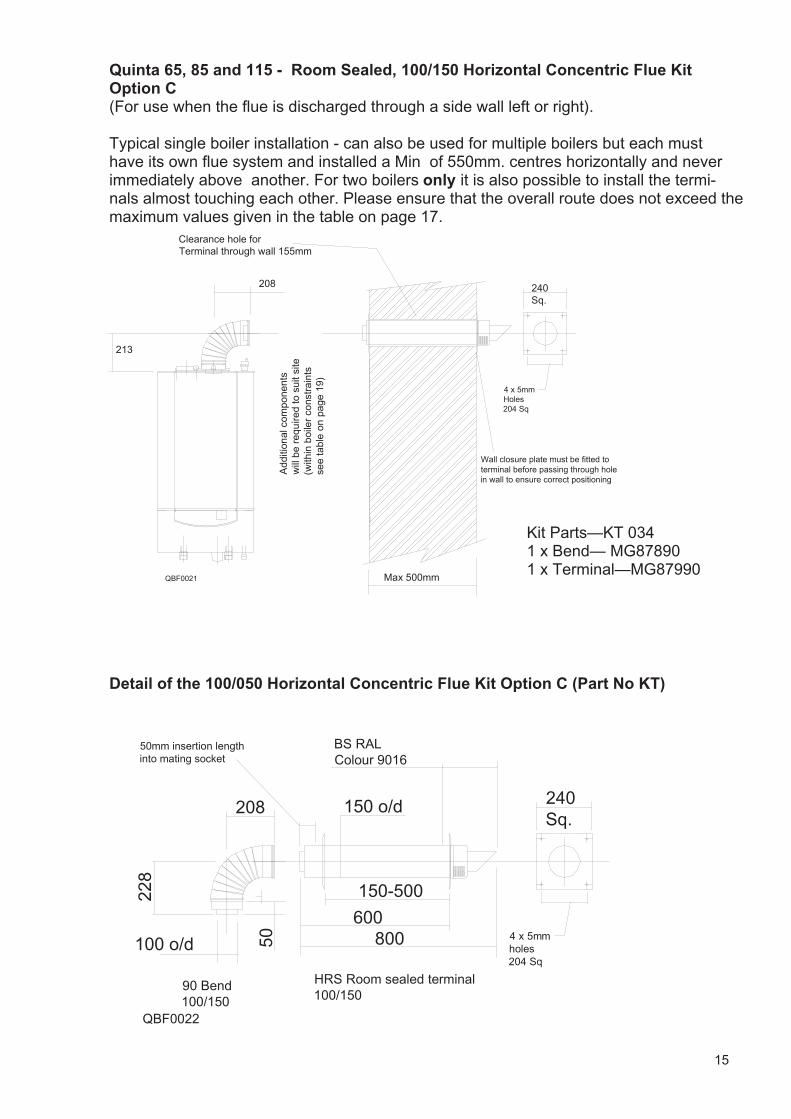
Quinta 65, 85 and 115 - Room Sealed, 100/150 Horizontal Concentric Flue Kit Option C (For use when the flue is discharged through a side wall left or right). Typical single boiler installation - can also be used for multiple boilers but each must have its own flue system and installed a Min of 550mm. centres horizontally and never immediately above another. For two boilers only it is also possible to install the termi-nals almost touching each other. Please ensure that the overall route does not exceed the maximum values given in the table on page 17.
213
Add
ition
al c
ompo
nent
sw
ill b
e re
quire
d to
sui
t site
(w
ithin
boi
ler
cons
trai
nts
see
tabl
e o
n p
age
19)
Clearance hole forTerminal through wall 155mm
208 240Sq.
4 x 5mm Holes204 Sq
Max 500mm
Wall closure plate must be fitted to terminal before passing through hole in wall to ensure correct positioning
QBF0021
Detail of the 100/050 Horizontal Concentric Flue Kit Option C (Part No KT)
240Sq.
BS RAL Colour 9016
150 o/d
4 x 5mm holes204 Sq
150-500
800600
HRS Room sealed terminal 100/150
50mm insertion lengthinto mating socket
QBF0022
90 Bend 100/150
228
50100 o/d
208
Kit Parts—KT 034 1 x Bend— MG87890 1 x Terminal—MG87990
16
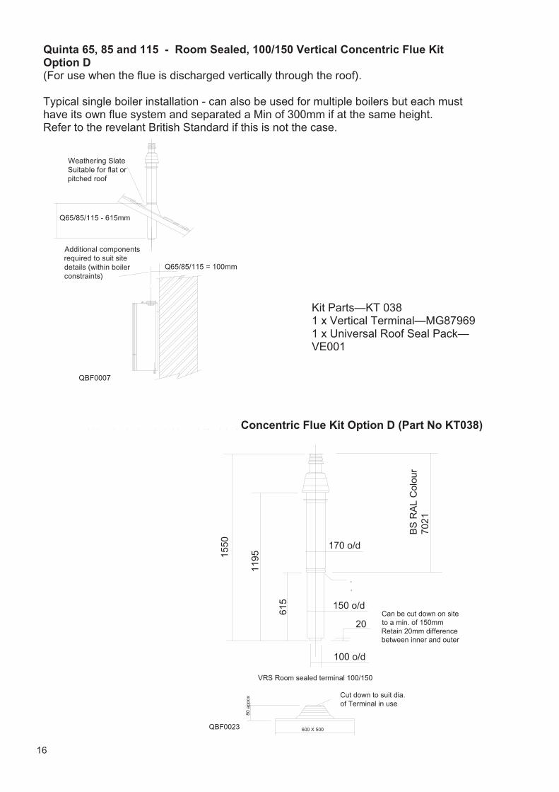
Quinta 65, 85 and 115 - Room Sealed, 100/150 Vertical Concentric Flue Kit Option D (For use when the flue is discharged vertically through the roof). Typical single boiler installation - can also be used for multiple boilers but each must have its own flue system and separated a Min of 300mm if at the same height. Refer to the revelant British Standard if this is not the case.
QBF0023
Can be cut down on site to a min. of 150mmRetain 20mm differencebetween inner and outer
600 X 500
Cut down to suit dia. of Terminal in use
80 a
ppox
BS
RA
L C
olou
r 70
21
VRS Room sealed terminal 100/150
.
.
170 o/d
150 o/d
100 o/d
20
615
119515
50
Detail of the Vertical 100/150 CConcentric Flue Kit Option D (Part No KT038)
Kit Parts—KT 038 1 x Vertical Terminal—MG87969 1 x Universal Roof Seal Pack—VE001
Q65/85/115 = 100mm
Weathering Slate Suitable for flat or pitched roof
QBF0007
Q65/85/115 - 615mm
Additional components required to suit site details (within boiler constraints)
17
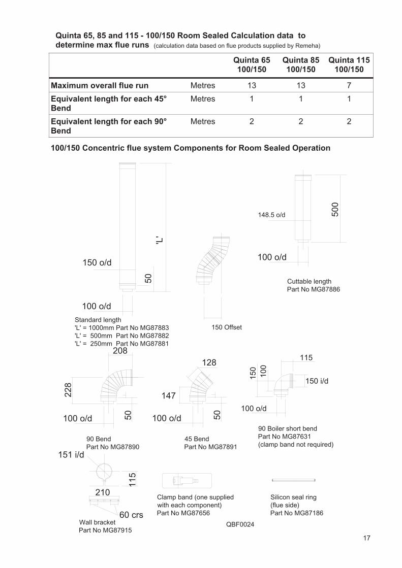
Quinta 65, 85 and 115 - 100/150 Room Sealed Calculation data to determine max flue runs
Quinta 65 100/150
Quinta 85 100/150
Maximum overall flue run Metres 13 13
Equivalent length for each 45° Bend
Metres 1 1
Equivalent length for each 90° Bend
Metres 2 2
Quinta 115 100/150
7
1
2
100/150 Concentric flue system Components for Room Sealed Operation
100 o/d
150 o/d
'L'
50
100 o/d
500
100 o/d 50
228
208
100 o/d 50
147
128
90 BendPart No MG87890
45 BendPart No MG87891
Cuttable lengthPart No MG87886
Standard length 'L' = 1000mm Part No MG87883'L' = 500mm Part No MG87882'L' = 250mm Part No MG87881
60 crs
210
151 i/d
Wall bracketPart No MG87915
115
Clamp band (one suppliedwith each component)Part No MG87656
Silicon seal ring(flue side)Part No MG87186
148.5 o/d
150 Offset
QBF0024
115
150 i/d
100 o/d
90 Boiler short bendPart No MG87631(clamp band not required)
150
100
(calculation data based on flue products supplied by Remeha)
18
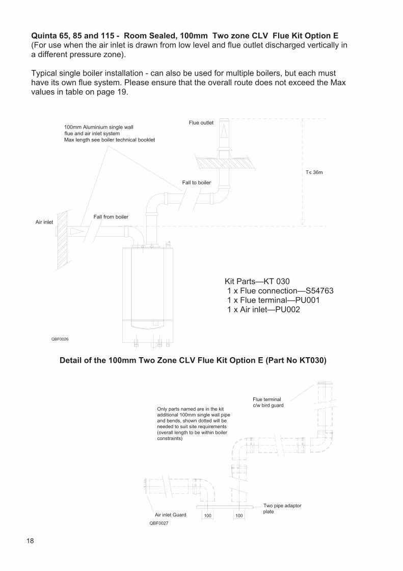
Quinta 65, 85 and 115 - Room Sealed, 100mm Two zone CLV Flue Kit Option E (For use when the air inlet is drawn from low level and flue outlet discharged vertically in a different pressure zone). Typical single boiler installation - can also be used for multiple boilers, but each must have its own flue system. Please ensure that the overall route does not exceed the Max values in table on page 19.
Fall to boiler
Air inletFall from boiler
100mm Aluminium single wall flue and air inlet systemMax length see boiler technical booklet
Flue outlet
QBF0026
QBF0027
100 Air inlet Guard
Flue terminal c/w bird guard
Only parts named are in the kitadditional 100mm single wall pipe and bends, shown dotted will be needed to suit site requirements(overall length to be within boiler constraints)
100
Two pipe adaptor plate
Detail of the 100mm Two Zone CLV Flue Kit Option E (Part No KT030)
Kit Parts—KT 030 1 x Flue connection—S54763 1 x Flue terminal—PU001 1 x Air inlet—PU002
T< 36m
19
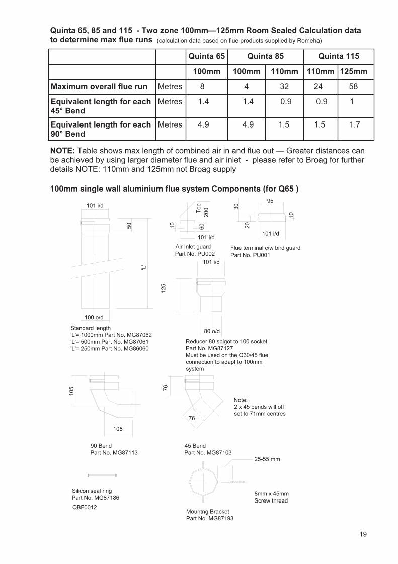
Quinta 65, 85 and 115 - Two zone 100mm—125mm Room Sealed Calculation data to determine max flue runs
Quinta 65 Quinta 115
100mm 100mm 110mm 110mm 125mm
Maximum overall flue run Metres 8 4 32 24 58
Equivalent length for each 45° Bend
Metres 1.4 1.4 0.9 0.9 1
Equivalent length for each 90° Bend
Metres 4.9 4.9 1.5 1.5 1.7
Quinta 85
NOTE: Table shows max length of combined air in and flue out — Greater distances can be achieved by using larger diameter flue and air inlet - please refer to Broag for further details NOTE: 110mm and 125mm not Broag supply
100mm single wall aluminium flue system Components (for Q65 )
'L'
101 i/d
100 o/d
Standard length'L'= 1000mm Part No. MG87062'L'= 500mm Part No. MG87061'L'= 250mm Part No. MG86060
105
105
90 BendPart No. MG87113
45 BendPart No. MG87103
76
76
125
101 i/d
80 o/d
Reducer 80 spigot to 100 socketPart No. MG87127Must be used on the Q30/45 flue connection to adapt to 100mm system
Silicon seal ringPart No. MG87186
50
Mountng BracketPart No. MG87193
8mm x 45mmScrew thread
25-55 mm
Note:2 x 45 bends will off set to 71mm centres
101 i/d
95
30
20Flue terminal c/w bird guard Part No. PU001
Air Inlet guardPart No. PU002
QBF0012
10
10
200
60
101 i/d
Top
(calculation data based on flue products supplied by Remeha)
20
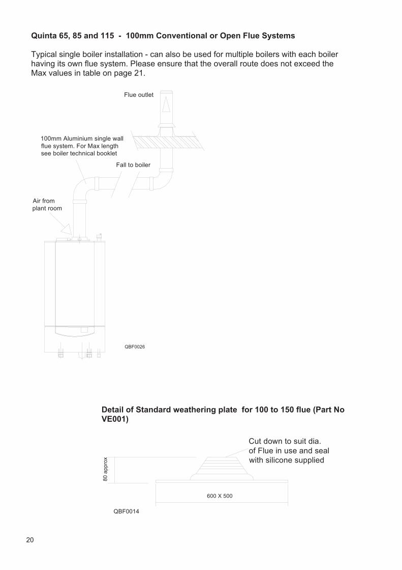
Fall to boiler
100mm Aluminium single wall flue system. For Max length see boiler technical booklet
Flue outlet
QBF0026
Air from plant room
Quinta 65, 85 and 115 - 100mm Conventional or Open Flue Systems Typical single boiler installation - can also be used for multiple boilers with each boiler having its own flue system. Please ensure that the overall route does not exceed the Max values in table on page 21.
QBF0014
600 X 500
Cut down to suit dia. of Flue in use and seal with silicone supplied
80 a
ppro
x
Detail of Standard weathering plate for 100 to 150 flue (Part No VE001)
21
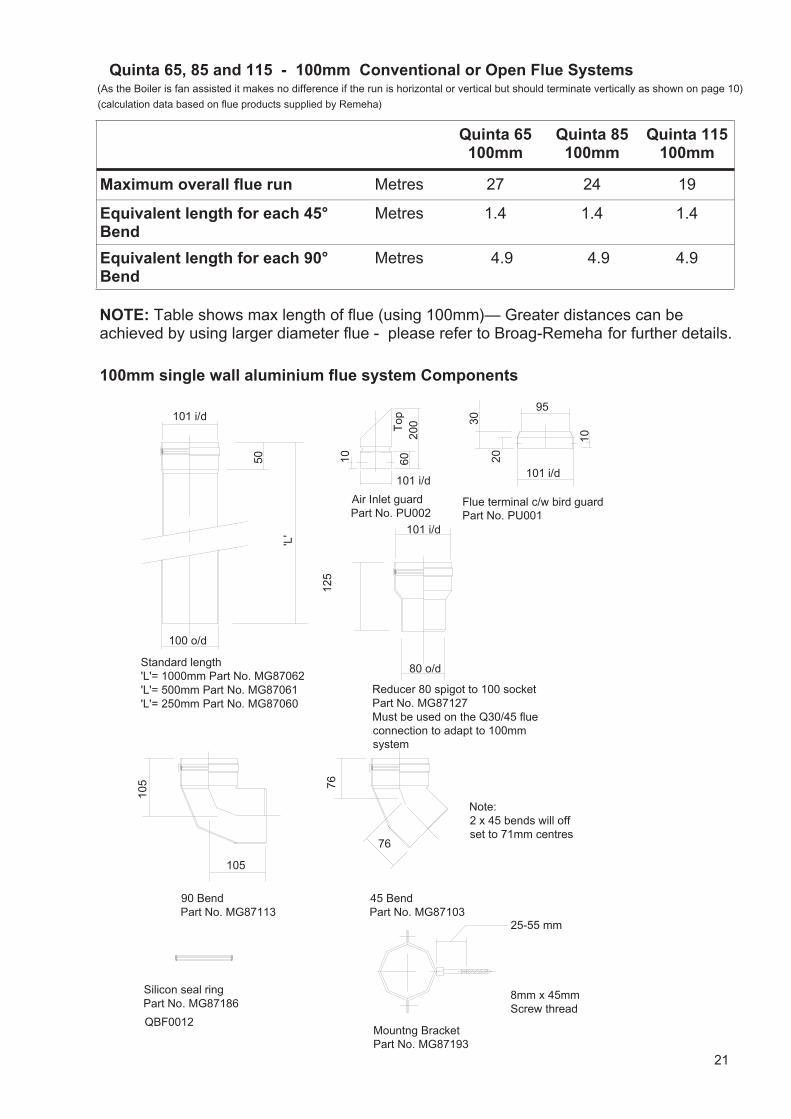
Quinta 65, 85 and 115 - 100mm Conventional or Open Flue Systems
Quinta 65 100mm
Quinta 85 100mm
Maximum overall flue run Metres 27 24
Equivalent length for each 45° Bend
Metres 1.4 1.4
Equivalent length for each 90° Bend
Metres 4.9 4.9
Quinta 115 100mm
19
1.4
4.9
NOTE: Table shows max length of flue (using 100mm)— Greater distances can be achieved by using larger diameter flue - please refer to Broag-Remeha for further details.
100mm single wall aluminium flue system Components
'L'
101 i/d
100 o/d
Standard length'L'= 1000mm Part No. MG87062'L'= 500mm Part No. MG87061'L'= 250mm Part No. MG87060
105
105
90 BendPart No. MG87113
45 BendPart No. MG87103
76
76
125
101 i/d
80 o/d
Reducer 80 spigot to 100 socketPart No. MG87127Must be used on the Q30/45 flue connection to adapt to 100mm system
Silicon seal ringPart No. MG87186
50
Mountng BracketPart No. MG87193
8mm x 45mmScrew thread
25-55 mm
Note:2 x 45 bends will off set to 71mm centres
101 i/d
95
30
20Flue terminal c/w bird guard Part No. PU001
Air Inlet guardPart No. PU002
QBF0012
10
10
200
60
101 i/d
Top
(As the Boiler is fan assisted it makes no difference if the run is horizontal or vertical but should terminate vertically as shown on page 10)
(calculation data based on flue products supplied by Remeha)
22
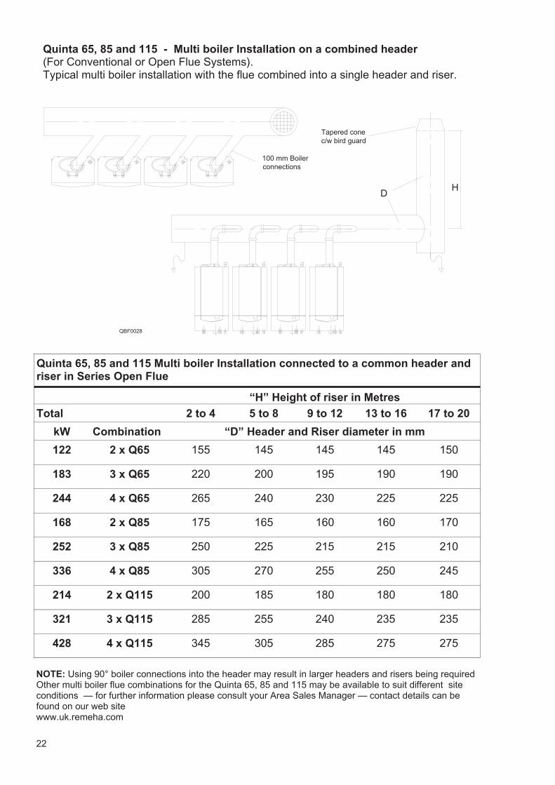
DH
100 mm Boiler connections
Tapered conec/w bird guard
QBF0028
Quinta 65, 85 and 115 - Multi boiler Installation on a combined header (For Conventional or Open Flue Systems). Typical multi boiler installation with the flue combined into a single header and riser.
Quinta 65, 85 and 115 Multi boiler Installation connected to a common header and riser in Series Open Flue
Total 2 to 4 5 to 8 9 to 12 13 to 16 17 to 20
kW Combination “D” Header and Riser diameter in mm
122 2 x Q65 155 145 145 145 150
183 3 x Q65 220 200 195 190 190
244 4 x Q65 265 240 230 225 225
168 2 x Q85 175 165 160 160 170
252 3 x Q85 250 225 215 215 210
336 4 x Q85 305 270 255 250 245
“H” Height of riser in Metres
214 2 x Q115 200 185 180 180 180
321 3 x Q115 285 255 240 235 235
428 4 x Q115 345 305 285 275 275
NOTE: Using 90° boiler connections into the header may result in larger headers and risers being required Other multi boiler flue combinations for the Quinta 65, 85 and 115 may be available to suit different site conditions — for further information please consult your Area Sales Manager — contact details can be found on our web site www.uk.remeha.com
23
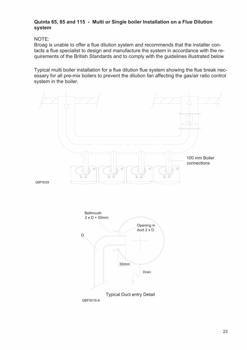
Quinta 65, 85 and 115 - Multi or Single boiler Installation on a Flue Dilution system NOTE: Broag is unable to offer a flue dilution system and recommends that the installer con-tacts a flue specialist to design and manufacture the system in accordance with the re-quirements of the British Standards and to comply with the guidelines illustrated below
30mm
D
Bellmouth2 x D + 50mm
Opening in duct 2 x D
Typical Duct entry DetailQBF0016-A
Drain
QBF0029
100 mm Boiler connections
Typical multi boiler installation for a flue dilution flue system showing the flue break nec-essary for all pre-mix boilers to prevent the dilution fan affecting the gas/air ratio control system in the boiler.
Desi
gned
and
pro
duce
d by
San
s Fr
ontie
re M
arke
ting
Com
mun
icat
ions
– 0
1273
487
800
– w
ww
.sans
fron
tiere
.co.
uk
Broag Ltd. Head Office
Remeha House
Molly Millars Lane
Wokingham
Berkshire RG41 2QP
T: 0118 978 3434
F: 0118 978 6977
www.remeha.co.uk
Remeha is committed to carbon offsetting
The data published in this technical sales leaflet is based on the latest information (at date of publication) and maybe subject to revisions. It should be read in conjunction with our full technical brochure (available on request). Wereserve the right to continuous development in both design and manufacture, therefore any changes to the technologyor equipment employed may not be retrospective, nor may we be obliged to adjust earlier supplies accordingly. Issue 12 date: 18/01/10