Embed Size (px)
Citation preview
WIRELESS MICROPHONE SYSTEMSBy Tim Vear
SELECTION AND OPERATION
A Shure Educational Publication
WIRELESS MICROPHONE SYSTEMSBy Tim Vear
SELECTION AND OPERATION

Introduction ........................................................................ 4
Part One Wireless Microphone Systems: How They Work
Chapter 1Basic Radio Principles ....................................................... 5
Radio Wave Transmission ........................................... 5Radio Wave Modulation .............................................. 7
Chapter 2Basic Radio Systems ......................................................... 10
System Description ..................................................... 10Input Sources ............................................................. 11Transmitter: General Description ................................. 11Transmitter: Audio Circuitry ......................................... 12Transmitter: Radio Circuitry ......................................... 14Receiver: General Description ..................................... 15Receiver: Radio Circuitry ............................................ 15Receiver: Audio Circuitry ............................................. 17Receiver: Squelch ....................................................... 17Receiver: Antenna Configuration ................................ 18Multipath .................................................................... 19Receiver: Diversity Techniques ................................... 19Antennas .................................................................... 21Antenna Cable ............................................................ 24Antenna Distribution ................................................... 24
Chapter 3Wireless System Operation ................................................ 26
Frequency Bands for Wireless Systems ...................... 26 VHF ............................................................................ 26UHF ............................................................................ 29Frequency Selection ................................................... 31System Compatibility ................................................... 31Operating Frequency Interactions: Intermodulation .......................................................... 31Internal Frequency interactions: LO, IF........................ 32Non-System Radio Interference .................................. 34Broadcast Television ................................................... 35White Space Devices .................................................. 37Broadcast Radio ......................................................... 38Other Radio Services .................................................. 38Non-Broadcast Sources .............................................. 38Range of Wireless Microphone Systems ..................... 39
Part Two Wireless Microphone Systems: How To Make Them Work
Chapter 4Wireless System Selection and Setup ............................... 40
System Selection ......................................................... 40System Setup: Transmitter ........................................... 41System Setup: Receivers ............................................. 43System Setup: Receiver Antennas............................... 45System Setup: Batteries............................................... 46System Checkout and Operation ................................. 47Networkable Wireless Systems .................................... 47“Intelligent” Wireless Systems...................................... 48Troubleshooting Wireless Microphone Systems ........... 49Troubleshooting Guide ................................................ 49
Chapter 5Application Notes ............................................................... 50
Presenters.................................................................... 50Musical Instruments .................................................... 50Vocalists....................................................................... 51Aerobic/Dance Instruction ........................................... 52Theater ........................................................................ 52Worship........................................................................ 53Conference/Corporate.................................................. 53Film/Videography......................................................... 54Broadcast .................................................................... 54Point-to-Point Wireless................................................. 55Conclusion................................................................... 58
Reference InformationAppendix A: Calculation of Intermodulation Products ........................................... 59Appendix B: U.S. Television Channels ........................ 61Appendix C: Technical Considerations for Digital Wireless Audio Systems .............................. 62Glossary of Terms and Specifications .......................... 65Included Illustrations ................................................... 68Biography ................................................................... 69
3
WIRELESSSelection and Operation of
Microphone Systems
Wireless
Ta b l e o f C o n t e n t s
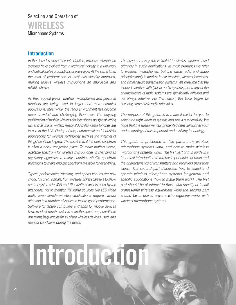
Introduction
WIRELESSSelection and Operation of
Microphone Systems
Introduction4
In the decades since their introduction, wireless microphonesystems have evolved from a technical novelty to a universaland critical tool in productions of every type. At the same time,the ratio of performance vs. cost has steadily improved, making today’s wireless microphone an affordable and reliable choice.
As their appeal grows, wireless microphones and personalmonitors are being used in larger and more complex applications. Meanwhile, the radio environment has becomemore crowded and challenging than ever. The ongoing proliferation of mobile wireless devices shows no sign of lettingup, and as this is written, nearly 200 million smartphones arein use in the U.S. On top of this, commercial and industrial applications for wireless technology such as the ‘internet ofthings’ continue to grow. The result is that the radio spectrumis often a noisy, congested place. To make matters worse, available spectrum for wireless microphones is changing asregulatory agencies in many countries shuffle spectrum allocations to make enough spectrum available for everything.
Typical performance, meeting, and sports venues are nowchock full of RF signals, from wireless ticket scanners to showcontrol systems to WiFi and Bluetooth networks used by theattendees, not to mention RF noise sources like LED videowalls. Even simple wireless applications require careful attention to a number of issues to insure good performance.Software for laptop computers and apps for mobile deviceshave made it much easier to scan the spectrum, coordinateoperating frequencies for all of the wireless devices used, andmonitor conditions during the event.
The scope of this guide is limited to wireless systems used primarily in audio applications. In most examples we refer to wireless microphones, but the same radio and audio principles apply to wireless in-ear monitors, wireless intercoms,and similar audio transmission systems. We presume that thereader is familiar with typical audio systems, but many of thecharacteristics of radio systems are significantly different andnot always intuitive. For this reason, this book begins by covering some basic radio principles.
The purpose of this guide is to make it easier for you to select the right wireless system and use it successfully. Wehope that the fundamentals presented here will further yourunderstanding of this important and evolving technology.
This guide is presented in two parts: how wireless microphone systems work, and how to make wireless microphone systems work. The first part of this guide is atechnical introduction to the basic principles of radio andthe characteristics of transmitters and receivers (how theywork). The second part discusses how to select and operate wireless microphone systems for general and specific applications (how to make them work). The firstpart should be of interest to those who specify or install professional wireless equipment while the second partshould be of use to anyone who regularly works with wireless microphone systems.
CHAPTER ONE
BASIC RADIO PRINCIPLES
Radio Wave TransmissionRadio refers to a class of time-varying electromagnetic
fields created by varying voltages and/or currents in certainphysical sources. These sources may be "artificial," such aselectrical power and electronic circuits, or "natural," such as the atmosphere (lightning) and stars (sunspots). The electromagnetic field variations radiate outward from thesource forming a pattern called a radio wave. Thus, a radiowave is a series of electromagnetic field variations travellingthrough space. Although, technically, any varying source ofvoltage or current produces a varying field near the source,here the term "radio wave" describes field variations thatpropagate a significant distance away from the source.
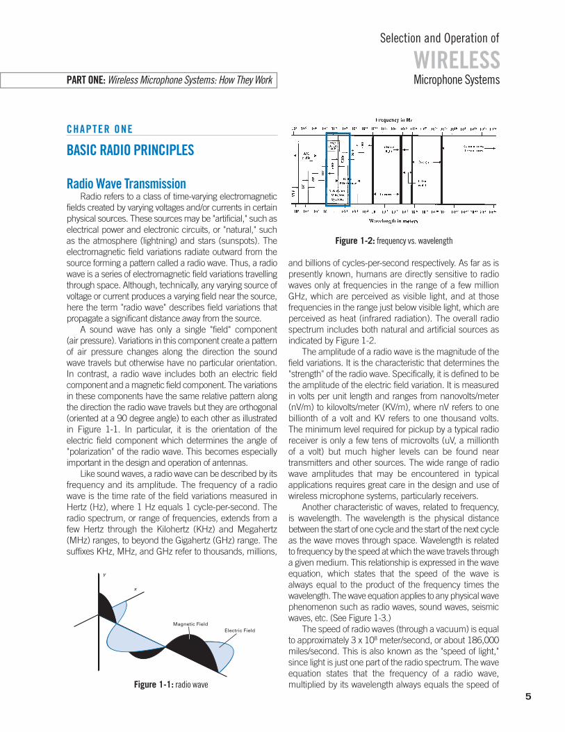
A sound wave has only a single "field" component (air pressure). Variations in this component create a patternof air pressure changes along the direction the sound wave travels but otherwise have no particular orientation. In contrast, a radio wave includes both an electric field component and a magnetic field component. The variationsin these components have the same relative pattern alongthe direction the radio wave travels but they are orthogonal(oriented at a 90 degree angle) to each other as illustratedin Figure 1-1. In particular, it is the orientation of the electric field component which determines the angle of "polarization" of the radio wave. This becomes especially important in the design and operation of antennas.
Like sound waves, a radio wave can be described by itsfrequency and its amplitude. The frequency of a radiowave is the time rate of the field variations measured inHertz (Hz), where 1 Hz equals 1 cycle-per-second. Theradio spectrum, or range of frequencies, extends from afew Hertz through the Kilohertz (KHz) and Megahertz(MHz) ranges, to beyond the Gigahertz (GHz) range. Thesuffixes KHz, MHz, and GHz refer to thousands, millions,
and billions of cycles-per-second respectively. As far as ispresently known, humans are directly sensitive to radiowaves only at frequencies in the range of a few million GHz, which are perceived as visible light, and at those frequencies in the range just below visible light, which areperceived as heat (infrared radiation). The overall radiospectrum includes both natural and artificial sources as indicated by Figure 1-2.
The amplitude of a radio wave is the magnitude of thefield variations. It is the characteristic that determines the"strength" of the radio wave. Specifically, it is defined to bethe amplitude of the electric field variation. It is measuredin volts per unit length and ranges from nanovolts/meter(nV/m) to kilovolts/meter (KV/m), where nV refers to onebillionth of a volt and KV refers to one thousand volts. The minimum level required for pickup by a typical radioreceiver is only a few tens of microvolts (uV, a millionth of a volt) but much higher levels can be found near transmitters and other sources. The wide range of radiowave amplitudes that may be encountered in typical applications requires great care in the design and use ofwireless microphone systems, particularly receivers.
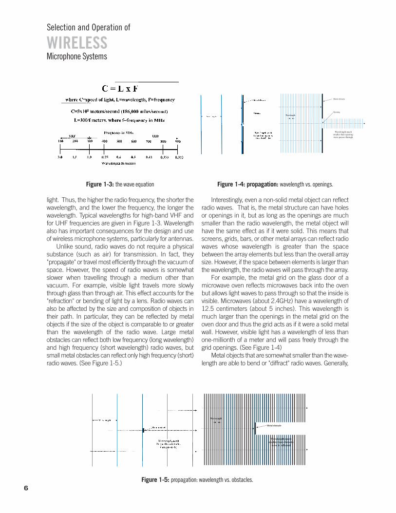
Another characteristic of waves, related to frequency, is wavelength. The wavelength is the physical distance between the start of one cycle and the start of the next cycleas the wave moves through space. Wavelength is related to frequency by the speed at which the wave travels througha given medium. This relationship is expressed in the waveequation, which states that the speed of the wave is always equal to the product of the frequency times the wavelength. The wave equation applies to any physical wave phenomenon such as radio waves, sound waves, seismicwaves, etc. (See Figure 1-3.)
The speed of radio waves (through a vacuum) is equalto approximately 3 x 10⁸ meter/second, or about 186,000miles/second. This is also known as the "speed of light,"since light is just one part of the radio spectrum. The waveequation states that the frequency of a radio wave, multiplied by its wavelength always equals the speed of
5
WIRELESSSelection and Operation of
Microphone SystemsPART ONE: Wireless Microphone Systems: How They Work
x
y
Magnetic FieldElectric Field
Figure 1-1: radio wave
Figure 1-2: frequency vs. wavelength
Microphone Systems
Selection and Operation of
WIRELESS
6
light. Thus, the higher the radio frequency, the shorter thewavelength, and the lower the frequency, the longer thewavelength. Typical wavelengths for high-band VHF andfor UHF frequencies are given in Figure 1-3. Wavelengthalso has important consequences for the design and useof wireless microphone systems, particularly for antennas.
Unlike sound, radio waves do not require a physicalsubstance (such as air) for transmission. In fact, they "propagate" or travel most efficiently through the vacuum ofspace. However, the speed of radio waves is somewhatslower when travelling through a medium other than vacuum. For example, visible light travels more slowlythrough glass than through air. This effect accounts for the"refraction" or bending of light by a lens. Radio waves canalso be affected by the size and composition of objects intheir path. In particular, they can be reflected by metal objects if the size of the object is comparable to or greaterthan the wavelength of the radio wave. Large metal obstacles can reflect both low frequency (long wavelength)and high frequency (short wavelength) radio waves, butsmall metal obstacles can reflect only high frequency (short)radio waves. (See Figure 1-5.)
Interestingly, even a non-solid metal object can reflectradio waves. That is, the metal structure can have holesor openings in it, but as long as the openings are muchsmaller than the radio wavelength, the metal object willhave the same effect as if it were solid. This means thatscreens, grids, bars, or other metal arrays can reflect radiowaves whose wavelength is greater than the space between the array elements but less than the overall arraysize. However, if the space between elements is larger thanthe wavelength, the radio waves will pass through the array.
For example, the metal grid on the glass door of a microwave oven reflects microwaves back into the ovenbut allows light waves to pass through so that the inside isvisible. Microwaves (about 2.4GHz) have a wavelength of12.5 centimeters (about 5 inches). This wavelength ismuch larger than the openings in the metal grid on theoven door and thus the grid acts as if it were a solid metalwall. However, visible light has a wavelength of less thanone-millionth of a meter and will pass freely through thegrid openings. (See Figure 1-4)
Metal objects that are somewhat smaller than the wave-length are able to bend or "diffract" radio waves. Generally,
Figure 1-3: the wave equation
Figure 1-5: propagation: wavelength vs. obstacles.
Wavelength
Figure 1-4: propagation: wavelength vs. openings.
7
Microphone Systems
Selection and Operation of
WIRELESS
the size, location, and quantity of metal in the vicinity of radiowaves will have significant effect on their behavior.
Non-metallic materials do not generally reflect radiowaves but are not completely transparent either. To somedegree, non-metallic substances generally "attenuate" orcause a loss in the strength of radio waves that pass throughthem. The amount of attenuation or loss is a function of the thickness and composition of the material and also a function of the radio wavelength. In practice, dense materials produce more losses than lighter materials andshort radio waves (high frequencies) are attenuated moreseverely than long radio waves (low frequencies). Thehuman body, for example, causes significant losses to shortradio waves passing through it.
A metal object that is large enough to reflect radio wavesor a non-metal object that is dense enough to attenuatethem can create a "shadow" in the path of the waves whichcan greatly hamper reception of radio in the area beyondthe object.
A final parallel between sound waves and radio waveslies in the nature of the overall radio wave pattern or "field"produced by various sources at a given receive location. Ina free-field condition (no reflections) the power level of aradio wave decreases as it propagates from its source at arate governed by the inverse-square law. This decrease is3dB for each doubling of distance. Note that for a soundwave, sound pressure level (SPL) decreases by 6dB for eachdoubling of distance. The numerical difference reflects thatthe radio calculation is a power ratio while the acoustic calculation is a pressure ratio. For either type of wave, at asufficient distance from the source, the wave will becometoo weak to detect.
If reflections are present (which is nearly always the caseindoors), the radio field (like a sound field) will include bothdirect waves (those that travel by the shortest path from thesource to the receive location) and indirect waves (those thatare reflected to the receive location). Because the indirectwaves travel a longer distance, they arrive at the receive location at some delay relative to the direct wave. The indirect waves can combine with the direct wave at the receive location to cause variations in the overall receivedfield strength. This phenomenon is called “multipath” andwill be discussed further in the description of radio receivers.Ultimately, the strength of a radio wave that arrives at a givenlocation, is equal to the strength of the original source minusthe amount of loss due to distance (inverse square loss), lossdue to material attenuation, and variations due to multipath.
After many reflections radio waves (like sound waves)become weaker and essentially non-directional. They eventually contribute to ambient "noise," that is, general radio
energy produced by many natural and man-made sourcesacross a wide range of frequencies. The strength of ambientradio noise is relatively constant in a given area, that is, itdoes not diminish with distance. The total radio field at agiven location consists of direct waves, indirect waves andradio noise.
Radio noise is nearly always considered to be undesirable. The direct and indirect waves may come fromboth the desired source (the intended transmission) andundesirable sources (other transmissions and general radioenergy emitters). Successful radio reception depends on a favorable level of the desired transmission comparedto the level of undesirable transmissions and noise at thespecific receive location.
Radio Wave ModulationThis discussion of radio transmission has so far dealt
only with the basic radio wave. It is also necessary to consider how information is carried by these waves. Again, a comparison of sound waves and radio waves maybe useful for illustration.
Audio "information" is transmitted by sound waveswhich consist of air pressure variations over a large rangeof amplitudes and frequencies. This combination of varying amplitudes and varying frequencies creates ahighly complex sound field.
These varying pressure waves are able to be processeddirectly by our auditory systems to perceive speech, music,and other intelligible sounds (information).
Radio "information" is generally transmitted using onlyone frequency. This single electromagnetic wave is varied inamplitude, frequency, or some other characteristic (such asphase) and for most radio transmissions neither the wavenor its variation can be detected or processed directly byhuman senses. In fact, the wave itself is not the informationbut rather the "carrier" of the information. The information iscontained in the amplitude variation or frequency variation,for example. When a radio wave contains information it iscalled a radio "signal." The general term for this information-carrying variation of radio waves is "modulation." If the amplitude of the wave is varied the technique is called Amplitude Modulation or AM. If the frequency is varied, it iscalled Frequency Modulation or FM. If the phase is varied,it is called Phase Modulation or PM.
The amount of information that can be carried in a radiosignal depends on the type of modulation and the level ofmodulation that can be applied to the basic radio wave.Presently, both analog and digital modulation techniques arefound in high quality wireless systems. Greater levels of modulation allow more information to be transmitted. The
information capacity of the radio signal is also related to thefrequency of the basic radio wave. Higher frequency radiowaves can generally carry more information than lower frequency waves. The information “efficiency” of both analog and digital modulation schemes is limited by physicsto some extent, but may also be limited by regulatory agencies (such as the FCC in the United States).
Both analog and digital modulation utilize the same variables noted above: amplitude modulation, frequencymodulation, and/or phase modulation. However, analogtransmissions modulate the radio wave over a continuousrange of values while digital transmissions modulate theradio wave only in discreet steps. This is the fundamental difference between the two schemes: analog modulationcan have any value within the modulation limits while digital modulation can have only certain specific valueswithin its modulation limits.
The other major difference between analog signal modulation and digital signal modulation is the relationshipof the modulated carrier to the original information. An analog radio signal has the characteristics of the original information represented directly in the transmitted signal.For example, the modulation rate and modulation amountof an analog wireless microphone signal correspond proportionally to the frequency and amplitude of the originalaudio source.
A digital wireless microphone system necessarily includes an initial analog-to-digital conversion step (ADC) inthe transmitter and a final digital-to-analog conversion (DAC)step in the receiver. In the transmitter, the ADC produces adigital data stream that is ultimately used to modulate thecarrier. This data stream is recovered from the transmittedsignal in the receiver and is used to reconstruct the originalanalog information.
The basic method of transmitting digital data in a radiosignal is a step-wise modulation of the carrier called "shiftkeying". As noted earlier, there are three principal radio waveparameters that can be modulated: amplitude, frequency,and/or phase. The names of the corresponding digital modulation techniques are ASK (amplitude shift key), FSK(frequency shift key), and PSK (phase shift key). It is alsopossible to combine multiple digital modulation techniquesto transmit more information.
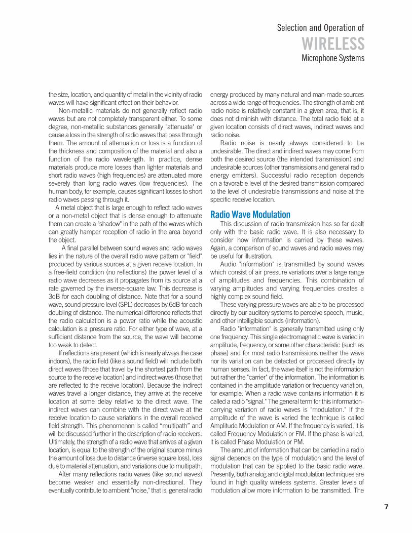
For AM signals, the radio wave has a single (constant)frequency of some basic amplitude (determined by thetransmitter power). This amplitude is varied up and down(modulated) by the transmitting signal to create the corresponding radio signal.
In an analog AM signal, the rate of modulation is equalto the frequency of the audio signal and the amount of modulation is proportional to the amplitude (loudness) of the audio signal. Primarily due to regulatory limits, an analog AM transmission typically allows an audio signal ofonly limited frequency response (about 50-9000 Hz) andlimited dynamic range (about 50 dB). (See Figure 1-6a.)
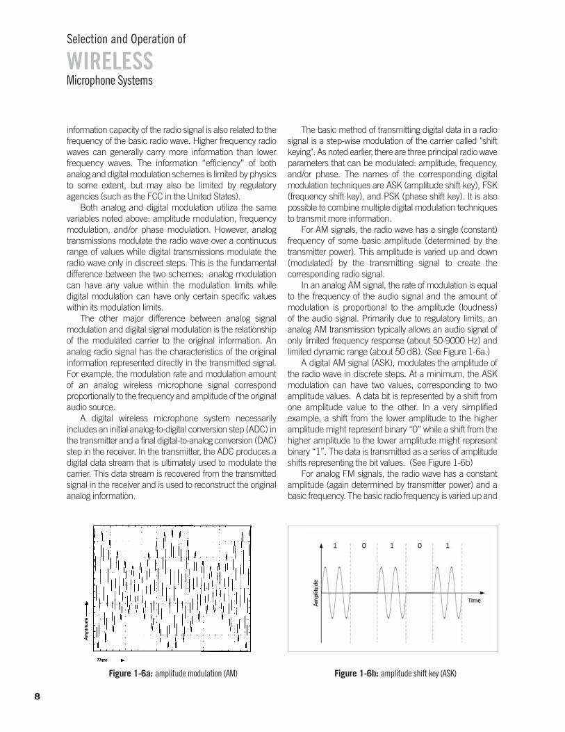
A digital AM signal (ASK), modulates the amplitude ofthe radio wave in discrete steps. At a minimum, the ASKmodulation can have two values, corresponding to two amplitude values. A data bit is represented by a shift fromone amplitude value to the other. In a very simplified example, a shift from the lower amplitude to the higher amplitude might represent binary “0” while a shift from thehigher amplitude to the lower amplitude might represent binary “1”. The data is transmitted as a series of amplitudeshifts representing the bit values. (See Figure 1-6b)
For analog FM signals, the radio wave has a constantamplitude (again determined by transmitter power) and abasic frequency. The basic radio frequency is varied up and
Microphone Systems
Selection and Operation of
WIRELESS
8
Figure 1-6b: amplitude shift key (ASK)Figure 1-6a: amplitude modulation (AM)
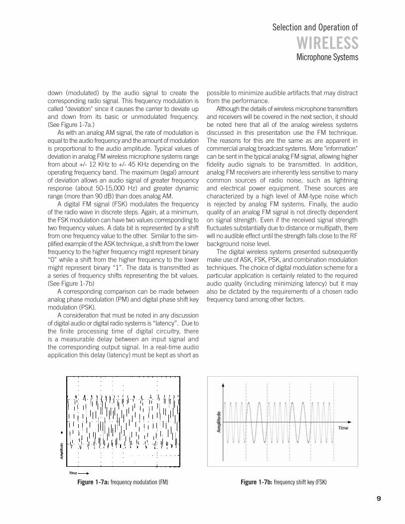
down (modulated) by the audio signal to create the corresponding radio signal. This frequency modulation iscalled "deviation" since it causes the carrier to deviate upand down from its basic or unmodulated frequency. (See Figure 1-7a.)
As with an analog AM signal, the rate of modulation isequal to the audio frequency and the amount of modulationis proportional to the audio amplitude. Typical values of deviation in analog FM wireless microphone systems rangefrom about +/- 12 KHz to +/- 45 KHz depending on the operating frequency band. The maximum (legal) amountof deviation allows an audio signal of greater frequency response (about 50-15,000 Hz) and greater dynamicrange (more than 90 dB) than does analog AM.
A digital FM signal (FSK) modulates the frequency of the radio wave in discrete steps. Again, at a minimum,the FSK modulation can have two values corresponding totwo frequency values. A data bit is represented by a shiftfrom one frequency value to the other. Similar to the sim-plified example of the ASK technique, a shift from the lowerfrequency to the higher frequency might represent binary“0” while a shift from the higher frequency to the lowermight represent binary “1”. The data is transmitted as a series of frequency shifts representing the bit values. (See Figure 1-7b)
A corresponding comparison can be made betweenanalog phase modulation (PM) and digital phase shift keymodulation (PSK).
A consideration that must be noted in any discussionof digital audio or digital radio systems is “latency”. Due tothe finite processing time of digital circuitry, there is a measurable delay between an input signal and the corresponding output signal. In a real-time audio application this delay (latency) must be kept as short as
possible to minimize audible artifacts that may distractfrom the performance.
Although the details of wireless microphone transmittersand receivers will be covered in the next section, it shouldbe noted here that all of the analog wireless systems discussed in this presentation use the FM technique. The reasons for this are the same as are apparent in commercial analog broadcast systems. More "information"can be sent in the typical analog FM signal, allowing higherfidelity audio signals to be transmitted. In addition, analog FM receivers are inherently less sensitive to manycommon sources of radio noise, such as lightning and electrical power equipment. These sources are characterized by a high level of AM-type noise which is rejected by analog FM systems. Finally, the audio quality of an analog FM signal is not directly dependenton signal strength. Even if the received signal strengthfluctuates substantially due to distance or multipath, therewill no audible effect until the strength falls close to the RFbackground noise level.
The digital wireless systems presented subsequentlymake use of ASK, FSK, PSK, and combination modulationtechniques. The choice of digital modulation scheme for aparticular application is certainly related to the requiredaudio quality (including minimizing latency) but it may also be dictated by the requirements of a chosen radio frequency band among other factors.
Microphone Systems
Selection and Operation of
WIRELESS
9
Figure 1-7b: frequency shift key (FSK)Figure 1-7a: frequency modulation (FM)
CHAPTER TWO
BASIC RADIO SYSTEMS
System DescriptionThe function of a radio or "wireless" system is to send
information in the form of a radio signal. In this presentation,the information is assumed to be an audio signal, but ofcourse video, data, or control signals can all be sent via radiowaves. In each case, the information must be converted toa radio signal, transmitted, received, and converted back toits original form. The initial conversion consists of using theoriginal information to create a radio signal by "modulating"a basic radio wave. In the final conversion, a complementarytechnique is used to "demodulate" the radio signal to recover the original information.
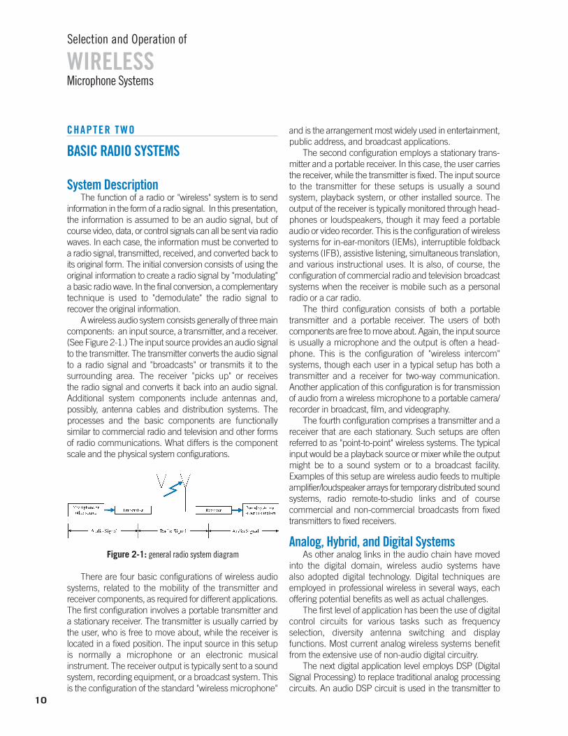
A wireless audio system consists generally of three maincomponents: an input source, a transmitter, and a receiver.(See Figure 2-1.) The input source provides an audio signalto the transmitter. The transmitter converts the audio signalto a radio signal and "broadcasts" or transmits it to the surrounding area. The receiver "picks up" or receives the radio signal and converts it back into an audio signal. Additional system components include antennas and, possibly, antenna cables and distribution systems. Theprocesses and the basic components are functionally similar to commercial radio and television and other formsof radio communications. What differs is the componentscale and the physical system configurations.
There are four basic configurations of wireless audiosystems, related to the mobility of the transmitter and receiver components, as required for different applications.The first configuration involves a portable transmitter anda stationary receiver. The transmitter is usually carried bythe user, who is free to move about, while the receiver is located in a fixed position. The input source in this setupis normally a microphone or an electronic musical instrument. The receiver output is typically sent to a soundsystem, recording equipment, or a broadcast system. Thisis the configuration of the standard "wireless microphone"
and is the arrangement most widely used in entertainment,public address, and broadcast applications.
The second configuration employs a stationary trans-mitter and a portable receiver. In this case, the user carriesthe receiver, while the transmitter is fixed. The input sourceto the transmitter for these setups is usually a sound system, playback system, or other installed source. Theoutput of the receiver is typically monitored through head-phones or loudspeakers, though it may feed a portableaudio or video recorder. This is the configuration of wirelesssystems for in-ear-monitors (IEMs), interruptible foldbacksystems (IFB), assistive listening, simultaneous translation,and various instructional uses. It is also, of course, the configuration of commercial radio and television broadcastsystems when the receiver is mobile such as a personalradio or a car radio.
The third configuration consists of both a portable transmitter and a portable receiver. The users of both components are free to move about. Again, the input sourceis usually a microphone and the output is often a head-phone. This is the configuration of "wireless intercom" systems, though each user in a typical setup has both atransmitter and a receiver for two-way communication. Another application of this configuration is for transmissionof audio from a wireless microphone to a portable camera/recorder in broadcast, film, and videography.
The fourth configuration comprises a transmitter and a receiver that are each stationary. Such setups are often referred to as "point-to-point" wireless systems. The typicalinput would be a playback source or mixer while the outputmight be to a sound system or to a broadcast facility. Examples of this setup are wireless audio feeds to multipleamplifier/loudspeaker arrays for temporary distributed soundsystems, radio remote-to-studio links and of course commercial and non-commercial broadcasts from fixedtransmitters to fixed receivers.
Analog, Hybrid, and Digital SystemsAs other analog links in the audio chain have moved
into the digital domain, wireless audio systems have also adopted digital technology. Digital techniques are employed in professional wireless in several ways, each offering potential benefits as well as actual challenges.
The first level of application has been the use of digitalcontrol circuits for various tasks such as frequency selection, diversity antenna switching and display functions. Most current analog wireless systems benefitfrom the extensive use of non-audio digital circuitry.
The next digital application level employs DSP (DigitalSignal Processing) to replace traditional analog processingcircuits. An audio DSP circuit is used in the transmitter to
10
WIRELESSSelection and Operation of
Microphone Systems
Figure 2-1: general radio system diagram
optimize the input signal for transmission and a comple-mentary audio DSP is used in the receiver to optimize theoutput signal. Because the radio transmission path is still inthe analog domain, these are often called “hybrid” systems.
The highest level of digital implementation uses a fullydigital transmission path. The input signal is digitized in thetransmitter and can remain in the digital domain until thereceiver output, or even deliver a digital signal from the receiver to subsequent digital equipment.
Input SourcesThe input source is any device that provides a suitable
audio signal to the transmitter. "Suitable audio signal"means an electrical signal within a certain frequency range(audio), voltage range (microphone level or line level), andimpedance range (low or high) that can be handled by thetransmitter. Though this places some limits on inputsources, it will be seen that almost any type of audio signalcan be used with one system or another.
The most common input source is a microphone,which may take any one of a variety of forms: handheld,lavaliere, headworn, instrument-mounted, etc. The audiosignal provided by this source is audio frequency, microphone level, and usually low impedance. Since the"wireless" part of the wireless microphone only serves toreplace the cable, ideally, the characteristics and performance of a particular microphone should not changewhen used as part of a wireless microphone system.Therefore, the selection of microphone type for a wirelessmicrophone system should be made following the sameguidelines as for wired microphones. The usual choices ofoperating principle (dynamic/condenser), frequency response (flat/shaped), directionality (omnidirectional/ unidirectional), electrical output (balanced/ unbalanced,low or high impedance), and physical design (size, shape,mounting, etc.) must still be made correctly. Problems thatresult from improper microphone choice will only be aggravated in a wireless application.
Another widely encountered input source is an electronic musical instrument, such as an electric guitar,electric bass, or portable electronic keyboard. The signalfrom these sources is again audio frequency, microphoneor line level, and usually high impedance. The potentiallyhigher signal levels and high impedances can affect transmitter choice and operation.
Finally, general audio signal sources such as mixer outputs, portable music players, laptop computers, etc.may be considered. These exhibit a wide range of levelsand impedances. However, as long as these characteristicsare within the input capabilities of the transmitter they maybe successfully used.
Transmitter: General DescriptionTransmitters can be either fixed or portable as mentioned
earlier. Regardless of type, transmitters usually feature a single audio input (line or microphone type), various controls and indicators and a single antenna. Internally, theyare also functionally the same, except for the power supply:AC power for fixed types and battery power for portable models. The important features of transmitter design will bepresented in the context of portable units.
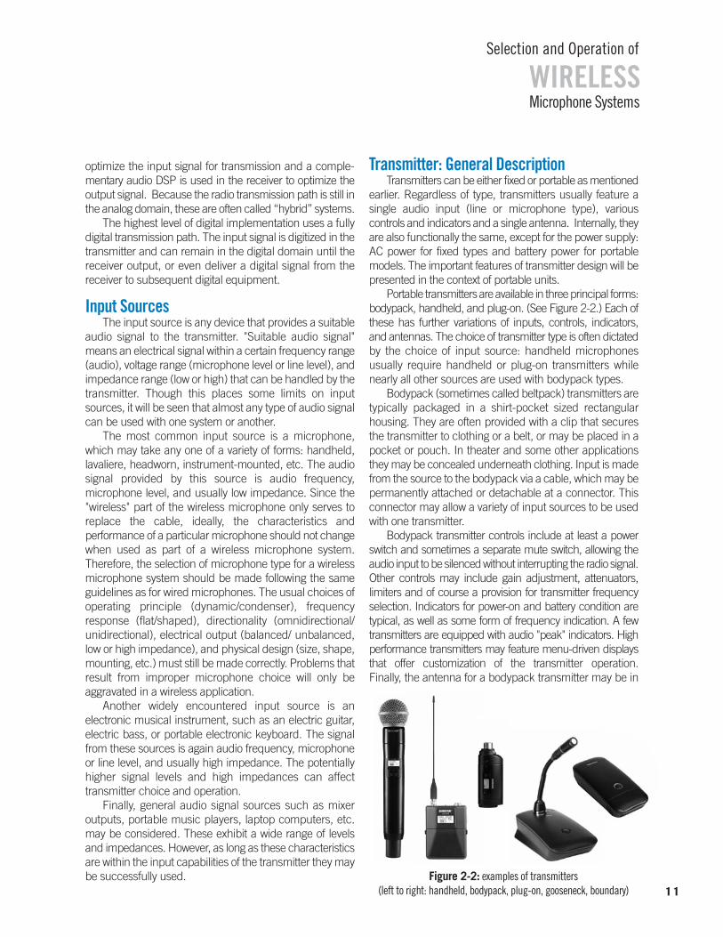
Portable transmitters are available in three principal forms:bodypack, handheld, and plug-on. (See Figure 2-2.) Each ofthese has further variations of inputs, controls, indicators, and antennas. The choice of transmitter type is often dictatedby the choice of input source: handheld microphones usually require handheld or plug-on transmitters whilenearly all other sources are used with bodypack types.
Bodypack (sometimes called beltpack) transmitters aretypically packaged in a shirt-pocket sized rectangular housing. They are often provided with a clip that securesthe transmitter to clothing or a belt, or may be placed in apocket or pouch. In theater and some other applicationsthey may be concealed underneath clothing. Input is madefrom the source to the bodypack via a cable, which may bepermanently attached or detachable at a connector. Thisconnector may allow a variety of input sources to be usedwith one transmitter.
Bodypack transmitter controls include at least a powerswitch and sometimes a separate mute switch, allowing theaudio input to be silenced without interrupting the radio signal.Other controls may include gain adjustment, attenuators, limiters and of course a provision for transmitter frequencyselection. Indicators for power-on and battery condition are typical, as well as some form of frequency indication. A fewtransmitters are equipped with audio "peak" indicators. Highperformance transmitters may feature menu-driven displaysthat offer customization of the transmitter operation. Finally, the antenna for a bodypack transmitter may be in
WIRELESSSelection and Operation of
Microphone Systems
11Figure 2-2: examples of transmitters
(left to right: handheld, bodypack, plug-on, gooseneck, boundary)
the form of a flexible attached wire, a detachable short"rubber ducky" type, or the input source cable itself, suchas a guitar cable or lavaliere microphone cable. In somemodels the antenna is internal to the unit.
Handheld transmitters, as the name implies, consist of ahandheld vocal microphone element integrated with a trans-mitter built into the handle. The complete package appearsonly slightly larger than a wired handheld microphone. It maybe carried in the hand or mounted on a microphone stand using an appropriate swivel adapter. Input from the microphone element is direct via an internal connector orwires. Some models have removable or interchangeable microphone elements. Handheld transmitter controls typicallyinclude power, gain adjustment, frequency selection andsometimes a mute function. Indicators are comparable to those in bodypack transmitters: power status, battery condition, frequency. Again, high performance models may feature menu-driven displays. Handheld transmitter antennas are usually concealed internally, though certaintypes (primarily UHF) may use a short external antenna.
"Plug-on" transmitters are a special type designed to attach directly to a typical handheld microphone, effectivelyallowing many standard microphones to become "wireless."The transmitter is contained in a small rectangular or cylindrical housing with an integral female XLR-type inputconnector. Controls and indicators are comparable to thosefound in bodypack types and the antenna is usually internal.
Two additional transmitter types are those integratedwith a gooseneck microphone or with a boundary micro-phone. These are frequently found in conference andmeeting room applications when it is not practical to usetraditional wired versions. The transmitter circuitry is thesame as is used in bodypack types but the antenna is internal. Again, the microphone characteristics are dictated by the application requirements.
While transmitters vary considerably in their external appearance, internally they all must accomplish the sametask: use the input audio signal to modulate a radio carrierand transmit the resulting radio signal effectively. Thoughthere are many different ways to engineer wireless
transmitters, certain functional elements are common tomost current designs, whether analog or digital. It is usefulto describe these elements to gain some insight to the overall performance and use of wireless audio systems. (SeeFigure 2-3.) The similarities and differences between analogand digital approaches will be noted where appropriate.
Transmitter: Audio CircuitryThe first part of the typical transmitter is the input
circuitry. This section makes the proper electrical match between the input source and the rest of the transmitter. It must handle the expected range of input levels and present the correct impedance to the source. Gain controlsand impedance switches allow greater flexibility in some designs. In certain cases, the input circuitry also providesan electrical voltage to the source (for condenser microphone elements). Note that this “bias” voltage (typically about 5vdc) is only intended to operate the impedance converter in a miniature condenser element. It is not the same as phantom power that is used to operatea complete condenser microphone. However, some plug-ontransmitters are capable of providing phantom power to usewith standard design condenser microphones.
The signal from the input stage passes to the signalprocessing section, which optimizes the audio signal inseveral ways for the constraints imposed by radio trans-mission. While the input stage is generally an analog
WIRELESSSelection and Operation of
Microphone Systems
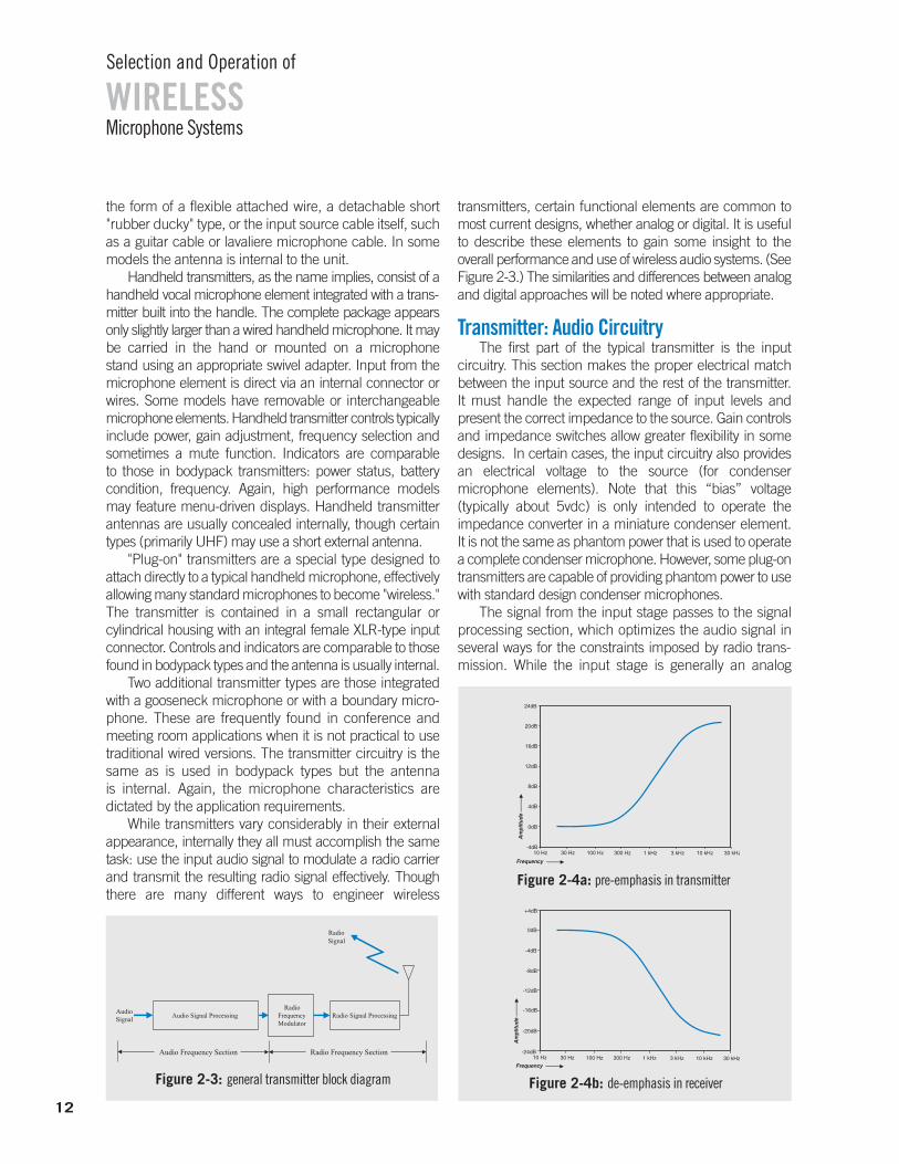
Figure 2-4b: de-emphasis in receiver
Figure 2-4a: pre-emphasis in transmitter
Figure 2-3: general transmitter block diagram
12
circuit, the signal processing which follows may be eitheranalog or digital, depending on whether the transmitter isfully analog, fully digital, or a hybrid type.
In a fully analog transmitter, the first process is a special equalization called pre-emphasis, that is employedto minimize the level of high frequency noise (hiss) that occurs during the FM transmission process. The "emphasis"is a specifically tailored boost of the high frequencies. Whenthis is coupled with an equal (but opposite) "de-emphasis"in the receiver, the effect is a reduction of high frequencynoise by up to 30 dB. (See Figures 2-4 a & b.)
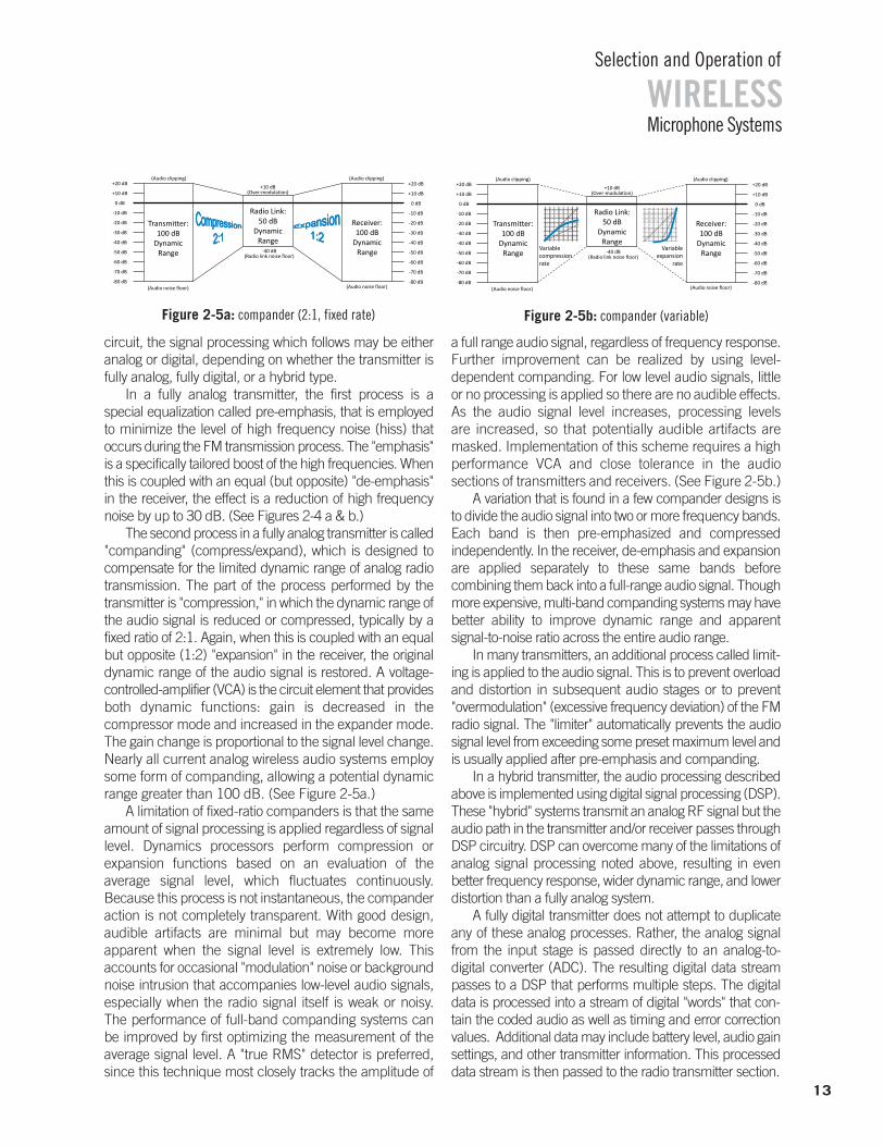
The second process in a fully analog transmitter is called"companding" (compress/expand), which is designed tocompensate for the limited dynamic range of analog radiotransmission. The part of the process performed by thetransmitter is "compression," in which the dynamic range ofthe audio signal is reduced or compressed, typically by afixed ratio of 2:1. Again, when this is coupled with an equalbut opposite (1:2) "expansion" in the receiver, the originaldynamic range of the audio signal is restored. A voltage-controlled-amplifier (VCA) is the circuit element that providesboth dynamic functions: gain is decreased in the compressor mode and increased in the expander mode.The gain change is proportional to the signal level change.Nearly all current analog wireless audio systems employsome form of companding, allowing a potential dynamicrange greater than 100 dB. (See Figure 2-5a.)
A limitation of fixed-ratio companders is that the sameamount of signal processing is applied regardless of signallevel. Dynamics processors perform compression or expansion functions based on an evaluation of the average signal level, which fluctuates continuously. Because this process is not instantaneous, the companderaction is not completely transparent. With good design, audible artifacts are minimal but may become more apparent when the signal level is extremely low. This accounts for occasional "modulation" noise or backgroundnoise intrusion that accompanies low-level audio signals,especially when the radio signal itself is weak or noisy. The performance of full-band companding systems canbe improved by first optimizing the measurement of theaverage signal level. A "true RMS" detector is preferred,since this technique most closely tracks the amplitude of
a full range audio signal, regardless of frequency response.Further improvement can be realized by using level-dependent companding. For low level audio signals, littleor no processing is applied so there are no audible effects.As the audio signal level increases, processing levels are increased, so that potentially audible artifacts are masked. Implementation of this scheme requires a high performance VCA and close tolerance in the audio sections of transmitters and receivers. (See Figure 2-5b.)
A variation that is found in a few compander designs isto divide the audio signal into two or more frequency bands.Each band is then pre-emphasized and compressed independently. In the receiver, de-emphasis and expansionare applied separately to these same bands before combining them back into a full-range audio signal. Thoughmore expensive, multi-band companding systems may havebetter ability to improve dynamic range and apparent signal-to-noise ratio across the entire audio range.
In many transmitters, an additional process called limit-ing is applied to the audio signal. This is to prevent overloadand distortion in subsequent audio stages or to prevent"overmodulation" (excessive frequency deviation) of the FMradio signal. The "limiter" automatically prevents the audiosignal level from exceeding some preset maximum level andis usually applied after pre-emphasis and companding.
In a hybrid transmitter, the audio processing describedabove is implemented using digital signal processing (DSP).These "hybrid" systems transmit an analog RF signal but theaudio path in the transmitter and/or receiver passes throughDSP circuitry. DSP can overcome many of the limitations ofanalog signal processing noted above, resulting in even better frequency response, wider dynamic range, and lowerdistortion than a fully analog system.
A fully digital transmitter does not attempt to duplicateany of these analog processes. Rather, the analog signalfrom the input stage is passed directly to an analog-to-digital converter (ADC). The resulting digital data streampasses to a DSP that performs multiple steps. The digitaldata is processed into a stream of digital "words" that con-tain the coded audio as well as timing and error correctionvalues. Additional data may include battery level, audio gainsettings, and other transmitter information. This processeddata stream is then passed to the radio transmitter section.
WIRELESSSelection and Operation of
Microphone Systems
13
Receiver: 100 dB
Dynamic Range
Transmitter:100 dB
Dynamic Range
Radio Link: 50 dB
Dynamic Range
(Audio noise floor) (Audio noise floor)
-40 dB (Radio link noise floor)
+10 dB (Over-modulation)
(Audio clipping) (Audio clipping)
+10 dB
+20 dB
-10 dB
0 dB
-20 dB
-30 dB
-50 dB
-60 dB
-40 dB
-70 dB
-80 dB
+10 dB
+20 dB
-10 dB
0 dB
-20 dB
-30 dB
-50 dB
-60 dB
-40 dB
-70 dB
-80 dB
Figure 2-5a: compander (2:1, fixed rate)
Transmitter:100 dB
Dynamic Range
Receiver: 100 dB
Dynamic Range
Transmitter:100 dB
Dynamic Range
Radio Link: 50 dB
Dynamic Range
(Audio noise floor) (Audio noise floor)
-40 dB (Radio link noise floor)
+10 dB (Over-modulation)
(Audio clipping) (Audio clipping)
+10 dB
+20 dB
-10 dB
0 dB
-20 dB
-30 dB
-50 dB
-60 dB
-40 dB
-70 dB
-80 dB
+10 dB
+20 dB
-10 dB
0 dB
-20 dB
-30 dB
-50 dB
-60 dB
-40 dB
-70 dB
-80 dB
Variable compression rate
Variable expansion
rate
Figure 2-5b: compander (variable)
Transmitter: Radio CircuitryIn a fully analog transmitter or in a hybrid transmitter,
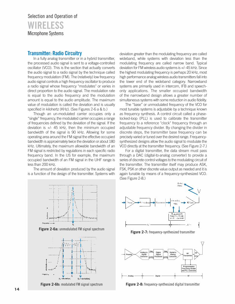
the processed audio signal is sent to a voltage-controlledoscillator (VCO). This is the section that actually convertsthe audio signal to a radio signal by the technique calledfrequency modulation (FM). The (relatively) low frequencyaudio signal controls a high frequency oscillator to producea radio signal whose frequency "modulates" or varies in direct proportion to the audio signal. The modulation rateis equal to the audio frequency and the modulationamount is equal to the audio amplitude. The maximumvalue of modulation is called the deviation and is usuallyspecified in kilohertz (KHz). (See Figures 2-6 a & b.)
Though an un-modulated carrier occupies only a “single” frequency, the modulated carrier occupies a rangeof frequencies defined by the deviation of the signal. If thedeviation is +/- 45 kHz, then the minimum occupied bandwidth of the signal is 90 kHz. Allowing for some operating area around the FM signal the effective occupiedbandwidth is approximately twice the deviation or about 180kHz. Ultimately, the maximum allowable bandwidth of anFM signal is restricted by regulations in each specific radiofrequency band. In the US for example, the maximum occupied bandwidth of an FM signal in the UHF range isless than 200 kHz.
The amount of deviation produced by the audio signalis a function of the design of the transmitter. Systems with
deviation greater than the modulating frequency are calledwideband, while systems with deviation less than the modulating frequency are called narrow band. Typical deviation for FM wireless audio systems is +/- 45 kHz. Sincethe highest modulating frequency is perhaps 20 kHz, mosthigh performance analog wireless audio transmitters fall intothe lower end of the wideband category. Narrowband systems are primarily used in intercom, IFB and speech-only applications. The smaller occupied bandwidth of the narrowband design allows a greater number of simultaneous systems with some reduction in audio fidelity.
The “base” or unmodulated frequency of the VCO formost tunable systems is adjustable by a technique knownas frequency synthesis. A control circuit called a phase-locked-loop (PLL) is used to calibrate the transmitter frequency to a reference "clock" frequency through an adjustable frequency divider. By changing the divider in discrete steps, the transmitter base frequency can beprecisely varied or tuned over the desired range. Frequency-synthesized designs allow the audio signal to modulate theVCO directly at the transmitter frequency. (See Figure 2-7.)
For a digital transmitter, the data stream must passthrough a DAC (digital-to-analog converter) to provide a series of discrete control voltages to the modulating circuit ofthe transmitter. The transmitter itself may produce ASK,FSK, PSK or other discrete value output as needed and it isagain tunable by means of a frequency-synthesized VCO.(See Figure 2-8.)
WIRELESSSelection and Operation of
Microphone Systems
Figure 2-6a: unmodulated FM signal spectrum
Figure 2-6b: modulated FM signal spectrum14
Figure 2-7: frequency-synthesized transmitter
Figure 2-8: frequency-synthesized digital transmitter

As noted earlier, the principal difference between theoutput of an analog (or hybrid) transmitter and a digital transmitter is in the nature of the modulation. The analogmodulation is continuous within its limits while the digitalmodulation has only discrete values within its limits. A consequence of this difference is that an analog signal isonly fully modulated when an audio signal is present whilea digital signal is fully modulated whether audio is presentor not. Thus the occupied bandwidth of a digital signal is constant while the occupied bandwidth of an analog signalvaries with the amplitude of the analog signal.
The final stage of both analog and digital transmittersis a radio frequency (RF) power amplifier. Typical outputpower values may range from about 1mW up to 250mW,though this is usually restricted by regulatory agencies. It isoften dependent on the modulation scheme and on thefrequency band of operation.
The last internal element of the transmitter is the powersupply. For portable transmitters, power is generally suppliedby batteries. Since the voltage level of batteries falls as theyare discharged, it is necessary to design the device to operateover a wide range of voltage or to employ voltage-regulating circuitry. Designs requiring a 9 V battery typically use the battery voltage directly. Transmitters using 1.5 V cells use DC-to-DC converters that maintain constant internal voltage levels by increasing battery current as the battery voltage decreases. This technique yields stable operation during theentire battery discharge cycle and permits very efficient battery operation. Units equipped with such voltage regula-tion must have a suitable protection circuit to avoid battery damage due to excess current draw. In addition, battery run-time indicators can be made more accurate since theymonitor both current and voltage throughout operation. In practice, battery life varies widely among transmitters, fromjust a few hours up to perhaps twenty hours, depending onoutput power, battery type, and overall circuit efficiency.
Receiver: General Description Receivers are available in both fixed and portable
designs. (See Figure 2-9.) Portable receivers resembleportable transmitters externally: they are characterized bysmall size, one or two outputs (microphone/line, head-phone), minimal controls and indicators (power, level), and (usually) a single antenna. Internally they are functionallysimilar to fixed receivers, again with the exception of thepower supply (battery vs. AC). The important features ofreceivers will be presented in the context of fixed units,which exhibit a greater range of choices.
Fixed receivers offer various outward features: units maybe free standing or rack-mountable; outputs may includebalanced/unbalanced microphone or line level as well as
headphones; indicators for power and audio/radio signallevel may be present; controls for power and output level areusually offered; antennas may be removable or permanentlyattached. Like transmitters, receivers can vary greatly inpackaging, but inside they must achieve a common goal:receive the radio signal efficiently and convert it into a suitable audio signal output. Once again it will be useful tolook at the main functional elements of the typical receiver.Differences between analog, hybrid, and digital receivers willbe noted where appropriate. (See Figure 2-10.)
Receiver: Radio CircuitryThe first section of receiver circuitry is the "front end."
Its function is to provide a first stage of radio frequency(RF) filtering to prevent unwanted radio signals from causing interference in subsequent stages. It should effectively reject signals that are substantially above orbelow the operating frequency of the receiver. For a singlefrequency receiver the front end can be fairly narrow. For a tunable receiver it must be wide enough to accommodate the desired range of frequencies if the frontend filter itself is not tunable.
In order to accommodate very wide tuning ranges, a track-tuned front-end filter is sometimes used. This is arelatively narrow filter that is automatically centered on thetuned frequency to prevent excessive off-channel radio energy from entering the receiver. (See Figure 2-11.)
15
WIRELESSSelection and Operation of
Microphone Systems
Figure 2-9: receiver examples
Figure 2-10: general receiver block diagram
fixed portable
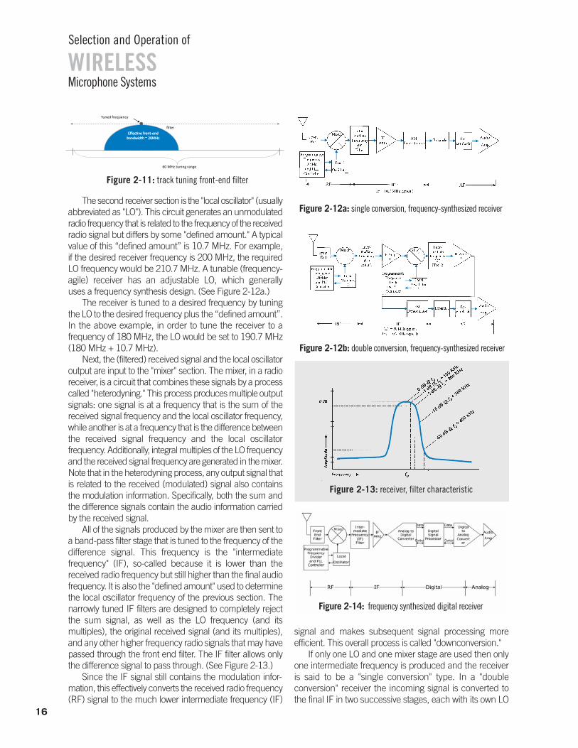
The second receiver section is the "local oscillator" (usuallyabbreviated as "LO"). This circuit generates an unmodulatedradio frequency that is related to the frequency of the receivedradio signal but differs by some "defined amount." A typicalvalue of this “defined amount” is 10.7 MHz. For example, if the desired receiver frequency is 200 MHz, the required LO frequency would be 210.7 MHz. A tunable (frequency-agile) receiver has an adjustable LO, which generally uses a frequency synthesis design. (See Figure 2-12a.)
The receiver is tuned to a desired frequency by tuningthe LO to the desired frequency plus the “defined amount”.In the above example, in order to tune the receiver to a frequency of 180 MHz, the LO would be set to 190.7 MHz(180 MHz + 10.7 MHz).
Next, the (filtered) received signal and the local oscillatoroutput are input to the "mixer" section. The mixer, in a radioreceiver, is a circuit that combines these signals by a processcalled "heterodyning." This process produces multiple outputsignals: one signal is at a frequency that is the sum of the received signal frequency and the local oscillator frequency,while another is at a frequency that is the difference betweenthe received signal frequency and the local oscillator frequency. Additionally, integral multiples of the LO frequencyand the received signal frequency are generated in the mixer.Note that in the heterodyning process, any output signal thatis related to the received (modulated) signal also containsthe modulation information. Specifically, both the sum andthe difference signals contain the audio information carriedby the received signal.
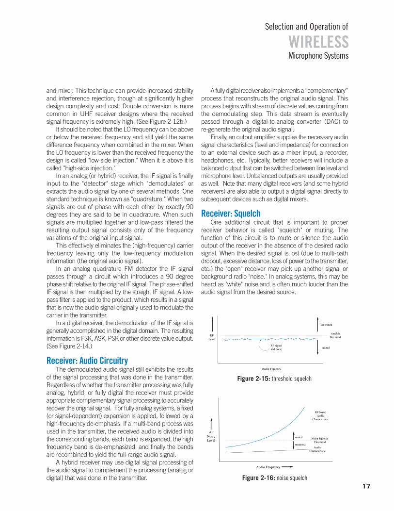
All of the signals produced by the mixer are then sent toa band-pass filter stage that is tuned to the frequency of thedifference signal. This frequency is the "intermediate frequency" (IF), so-called because it is lower than the received radio frequency but still higher than the final audiofrequency. It is also the "defined amount" used to determinethe local oscillator frequency of the previous section. Thenarrowly tuned IF filters are designed to completely rejectthe sum signal, as well as the LO frequency (and its multiples), the original received signal (and its multiples),and any other higher frequency radio signals that may havepassed through the front end filter. The IF filter allows onlythe difference signal to pass through. (See Figure 2-13.)
Since the IF signal still contains the modulation infor-mation, this effectively converts the received radio frequency(RF) signal to the much lower intermediate frequency (IF)
signal and makes subsequent signal processing more efficient. This overall process is called "downconversion."
If only one LO and one mixer stage are used then onlyone intermediate frequency is produced and the receiveris said to be a "single conversion" type. In a "double conversion" receiver the incoming signal is converted tothe final IF in two successive stages, each with its own LO
WIRELESSSelection and Operation of
Microphone Systems
60 MHz tuning range
Tuned frequency
filterEffective front-end Effective front-end
bandwidth ~ 20MHzbandwidth ~ 20MHz
Figure 2-11: track tuning front-end filter
16
Figure 2-12b: double conversion, frequency-synthesized receiver
Figure 2-12a: single conversion, frequency-synthesized receiver
Figure 2-14: frequency synthesized digital receiver
Figure 2-13: receiver, filter characteristic
and mixer. This technique can provide increased stabilityand interference rejection, though at significantly higherdesign complexity and cost. Double conversion is morecommon in UHF receiver designs where the received signal frequency is extremely high. (See Figure 2-12b.)
It should be noted that the LO frequency can be aboveor below the received frequency and still yield the samedifference frequency when combined in the mixer. Whenthe LO frequency is lower than the received frequency thedesign is called "low-side injection." When it is above it iscalled "high-side injection."
In an analog (or hybrid) receiver, the IF signal is finallyinput to the "detector" stage which "demodulates" or extracts the audio signal by one of several methods. Onestandard technique is known as "quadrature." When twosignals are out of phase with each other by exactly 90 degrees they are said to be in quadrature. When suchsignals are multiplied together and low-pass filtered theresulting output signal consists only of the frequency variations of the original input signal.
This effectively eliminates the (high-frequency) carrierfrequency leaving only the low-frequency modulation information (the original audio signal).
In an analog quadrature FM detector the IF signalpasses through a circuit which introduces a 90 degreephase shift relative to the original IF signal. The phase-shiftedIF signal is then multiplied by the straight IF signal. A low-pass filter is applied to the product, which results in a signalthat is now the audio signal originally used to modulate thecarrier in the transmitter.
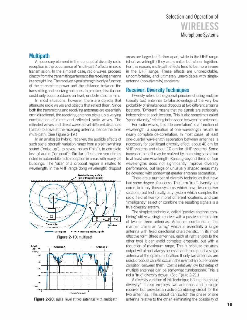
In a digital receiver, the demodulation of the IF signal isgenerally accomplished in the digital domain. The resultinginformation is FSK, ASK, PSK or other discrete value output.(See Figure 2-14.)
Receiver: Audio CircuitryThe demodulated audio signal still exhibits the results
of the signal processing that was done in the transmitter.Regardless of whether the transmitter processing was fullyanalog, hybrid, or fully digital the receiver must provide appropriate complementary signal processing to accuratelyrecover the original signal. For fully analog systems, a fixed(or signal-dependent) expansion is applied, followed by ahigh-frequency de-emphasis. If a multi-band process wasused in the transmitter, the received audio is divided intothe corresponding bands, each band is expanded, the highfrequency band is de-emphasized, and finally the bandsare recombined to yield the full-range audio signal.
A hybrid receiver may use digital signal processing ofthe audio signal to complement the processing (analog ordigital) that was done in the transmitter.
A fully digital receiver also implements a “complementary”process that reconstructs the original audio signal. Thisprocess begins with stream of discrete values coming fromthe demodulating step. This data stream is eventuallypassed through a digital-to-analog converter (DAC) to re-generate the original audio signal.
Finally, an output amplifier supplies the necessary audiosignal characteristics (level and impedance) for connectionto an external device such as a mixer input, a recorder,headphones, etc. Typically, better receivers will include abalanced output that can be switched between line level andmicrophone level. Unbalanced outputs are usually providedas well. Note that many digital receivers (and some hybridreceivers) are also able to output a digital signal directly tosubsequent devices such as digital mixers.
Receiver: SquelchOne additional circuit that is important to proper
receiver behavior is called "squelch" or muting. The function of this circuit is to mute or silence the audio output of the receiver in the absence of the desired radiosignal. When the desired signal is lost (due to multi-pathdropout, excessive distance, loss of power to the transmitter,etc.) the "open" receiver may pick up another signal orbackground radio "noise." In analog systems, this may beheard as "white" noise and is often much louder than theaudio signal from the desired source.
17
WIRELESSSelection and Operation of
Microphone Systems
Figure 2-16: noise squelch
RFLevel
Radio Frquency
un-muted
muted
squelchthreshold
RF signaland noise
AFNoiseLevel
Audio Frequency
RF NoiseAudio
Characteristic
Noise SquelchThreshold
AudioCharacteristic
muted
unmuted
Figure 2-15: threshold squelch

The traditional squelch circuit is an audio switch controlled by the radio signal level using a fixed or manually adjustable threshold (level). (See Figure 2-15.)
When the received signal strength falls below this levelthe output of the receiver is muted. Ideally, the squelchlevel should be set just above the background radio noiselevel or at the point where the desired signal is becomingtoo noisy to be acceptable. Higher settings of squelch levelrequire higher received signal strength to unmute the receiver. Since received signal strength decreases as transmission distance increases, higher squelch settingswill decrease the operating range of the system. One refinement of the standard squelch circuit is referred to as"noise squelch." (See Figure 2-16.) This technique relieson the fact that the audio from undesirable radio noise hasa great deal of high frequency energy compared to a typical audio signal. The noise squelch circuit comparesthe high frequency energy of the received signal to a reference voltage set by the squelch adjustment.
In this system the squelch control essentially determinesthe "quality" of signal (signal-to-noise ratio) required to unmute the receiver. This allows operation at lower squelchsettings with no likelihood of noise if the desired signal is lost.
A further refinement is known as "tone-key" or "tone-code" squelch. It enables the receiver to identify thedesired radio signal by means of a supra- or sub-audibletone that is generated in the transmitter and sent alongwith the normal audio signal. The receiver will unmute onlywhen it picks up a radio signal of adequate strength andalso detects the presence of the tone-key. This effectivelyprevents the possibility of noise from the receiver when thedesired transmitter signal is lost, even in the presence of a(non-tone-key) interfering signal at the same frequency.
Turn-on and turn-off delays are incorporated in thetransmitter tone-key circuits so that the transmitter powerswitch operates silently. When the transmitter is switchedon, the radio signal is activated immediately but the tone-key is briefly delayed, keeping the receiver muted until thesignal is stable. This masks any turn-on noise. When thetransmitter is switched off, the tone-key is deactivated
instantly, muting the receiver, but actual turn-off of thetransmitted signal is delayed slightly. This masks anyturnoff noise. As a result, the need for a separate muteswitch is eliminated. Finally, the tone-key signal is oftenused to transmit additional information to the receiver. This may include battery voltage, transmitter audio gain settings, transmitter type, and transmitter power level. (See Figure 2-17).
In a fully digital wireless system, the squelch process isnot directly related to the RF signal level, or to the signal-to-noise ratio or even to a specific tone-key frequency. Rather,the squelch circuit is activated whenever the error rate of thedetected digital data stream exceeds some preset thresholdthat could cause an audible artifact. This error rate dependence takes into account most of the audio and radiofactors that can degrade the signal quality and can generallyrespond more quickly and accurately than the standardsquelch mechanisms of analog or hybrid systems.
Receiver: Antenna ConfigurationFixed receivers are offered in two basic external
configurations: diversity and non-diversity. Non-diversityreceivers are equipped with a single antenna while diversity receivers generally have two antennas. Both systems may offer otherwise similar outward features: unitsmay be free standing or rack-mountable; outputs may include balanced/unbalanced microphone or line level aswell as headphones; indicators for power and audio/radiosignal level may be present; controls for power and audiooutput level are provided; antenna(s) may be removable orpermanently attached. (See Figure 2-18.)
Though diversity receivers tend to include more features than non-diversity types, the choice of diversityvs. non-diversity receiver is usually dictated by performanceand reliability considerations. Diversity receivers can significantly improve both qualities by minimizing the effectof variations in radio signal strength in a given receptionarea due to fading or due to multi-path. Fading is a loss of signal strength at excessive distance or because of shadowing or blocking of the radio wave. Multi-path is amore complex phenomenon but both mechanisms canadversely affect radio reception.
WIRELESSSelection and Operation of
Microphone Systems
non-diversity (single antenna) diversity (two antennas)
Figure 2-18: examples of receivers18
Figure 2-17: tone key squelch
MultipathA necessary element in the concept of diversity radio
reception is the occurrence of "multi-path" effects in radiotransmission. In the simplest case, radio waves proceeddirectly from the transmitting antenna to the receiving antennain a straight line. The received signal strength is only a functionof the transmitter power and the distance between thetransmitting and receiving antennas. In practice, this situationcould only occur outdoors on level, unobstructed terrain.
In most situations, however, there are objects that attenuate radio waves and objects that reflect them. Sinceboth the transmitting and receiving antennas are essentiallyomnidirectional, the receiving antenna picks up a varyingcombination of direct and reflected radio waves. The reflected waves and direct waves travel different distances(paths) to arrive at the receiving antenna, hence the termmulti-path. (See Figure 2-19.)
In an analog (or hybrid) receiver, the audible effects ofsuch signal strength variation range from a slight swishingsound ("noise-up"), to severe noises ("hits"), to completeloss of audio ("dropout"). Similar effects are sometimesnoted in automobile radio reception in areas with many tallbuildings. The "size" of a dropout region is related to wavelength: in the VHF range (long wavelength) dropout
areas are larger but farther apart, while in the UHF range(short wavelength) they are smaller but closer together. For this reason, multi-path effects tend to be more severein the UHF range. These effects are unpredictable, uncomfortable, and ultimately unavoidable with single-antenna (non-diversity) receivers.
Receiver: Diversity TechniquesDiversity refers to the general principle of using multiple
(usually two) antennas to take advantage of the very low probability of simultaneous dropouts at two different antennalocations. "Different" means that the signals are statistically independent at each location. This is also sometimes called"space diversity," referring to the space between the antennas.
For radio waves, this "de-correlation" is a function ofwavelength: a separation of one wavelength results innearly complete de-correlation. In most cases, at least one-quarter wavelength separation between antennas isnecessary for significant diversity effect: about 40 cm forVHF systems and about 10 cm for UHF systems. Someincreased benefit may be realized by increasing separationto at least one wavelength. Spacing beyond three or fourwavelengths does not significantly improve diversity performance, but large or unusually shaped areas maybe covered with somewhat greater antenna separation.
There are a number of diversity techniques that havehad some degree of success. The term "true" diversity hascome to imply those systems which have two receiver sections, but technically, any system which samples theradio field at two (or more) different locations, and can "intelligently" select or combine the resulting signals is atrue diversity system.
The simplest technique, called "passive antenna com-bining" utilizes a single receiver with a passive combinationof two or three antennas. Antennas combined in this manner create an "array," which is essentially a single antenna with fixed directional characteristic. In its most effective form (three antennas, each at right angles to theother two) it can avoid complete dropouts, but with a reduction of maximum range. This is because the array output will almost always be less than the output of a singleantenna at the optimum location. If only two antennas areused, dropouts can still occur in the event of an out-of-phasecondition between them. Cost is relatively low but setup ofmultiple antennas can be somewhat cumbersome. This isnot a "true" diversity design. (See Figure 2-21.)
A diversity variation of this technique is "antenna phasediversity." It also employs two antennas and a single receiver but provides an active combining circuit for thetwo antennas. This circuit can switch the phase of one antenna relative to the other, eliminating the possibility of
19
WIRELESSSelection and Operation of
Microphone Systems
Figure 2-20: signal level at two antennas with multipath
Figure 2-19: multipath

phase cancellation between them. However, switchingnoise is possible as well as other audible effects if switching is incorrect. Range is sometimes greater with favorable antenna combinations. Cost is relatively low.Setup requires somewhat greater antenna spacing for bestresults. (See Figure 2-22.)
The next variation, "antenna switching diversity," againconsists of a single receiver with two antennas. The receiver includes circuitry that selects the antenna with thebetter signal according to an evaluation of the radio signal.Switching noise is possible but this system avoids the possibility of phase cancellation between antennas because the antennas are never combined. Range is thesame as for a single antenna system. Cost is relatively lowand setup is convenient. (See Figure 2-23.)
In both of these active antenna diversity approaches, theswitching decision is based on the received signal quality ofa single receiver section. When the signal quality falls belowsome preset threshold, switching occurs immediately. If thenew antenna (or antenna combination) doesn’t improve thereception, the receiver must switch back to the original state.The lack of "predictive" ability often causes unnecessaryswitching, increasing the chance of noise. The switchingspeed is also critical: too fast and audible noise occurs, tooslow and a dropout may occur.
A variation of the antenna switching method offers predictive diversity capability using a microcontroller to optimize switching characteristics. A running average signal level and a maximum signal level are calculated byanalyzing the change in signal level over time. Comparingthe current average signal level to the most recent maximum signal level determines the switch action, basedon typical dropout characteristics. Small declines at highsignal levels indicate impending dropout, causing a switchto occur. At moderate signal levels, larger decreases are allowed before switching. At very low signal levelsswitching is curtailed to avoid unnecessary noise. Of course, if the signal level is increasing, no switching occurs. The onset of dropout can be more accurately recognized and countered, while eliminating switchingwhen there is little likelihood for improvement.
"Receiver switching diversity" is a widely used diversity system. It consists of two complete receiver sections, eachwith its own associated antenna, and circuitry that selectsthe audio from the receiver that has the better signal.Switching noise is possible but when properly designedthese systems can have very good dropout protection withlittle chance of other audible effects due to incorrect selection. This is because the system continuously comparesthe signal condition at each receiver output before switchingoccurs. Range is the same as with single antenna systems.Cost is higher, but setup is convenient. (See Figure 2-24.)
WIRELESSSelection and Operation of
Microphone Systems
Figure 2-23: antenna switching
Figure 2-22: antenna phase switching
Figure 2-21: passive antenna combining
Figure 2-24: receiver switching
Figure 2-25: receiver combining20
"Ratio combining diversity" also uses two complete receiver sections with associated antennas. This designtakes advantage of the fact that, most of the time, the signalat both antennas is useable. The diversity circuitry combinesthe outputs of the two receiver sections by proportionallymixing them rather than switching between them. At anygiven moment, the combination is proportional to the signal quality of each receiver. The output will usually consist of a mix of the two audio sections. In the case ofloss of reception at one antenna, the output is chosen fromthe other section. Excellent dropout protection is obtainedwith no possibility of switching noise since the diversity circuit is essentially an intelligent panpot, not a switch. (SeeFigure 2-25.) Signal-to-noise is improved by up to 3 dB.Range can be greater than with single antenna systems.Cost is somewhat higher, setup is convenient.
A properly implemented diversity system can yieldmeasurable improvements in reliability, range, and signal-to-noise ratio. This is particularly true if the RF environmentis severe (multipath), troubleshooting time is minimal (no rehearsal), or dropout-free performance is required(ideally always). The majority of wireless microphone systems today, both analog and digital, employ diversitydesigns at nearly all performance levels.
In some fully digital systems, it is possible to activelycombine the bit streams from multiple antenna/receiversections to compensate for data losses in individual bitstreams. As long as sufficient data can be assembled fromthis combination, reception can be maintained even in theevent of significant data losses in an individual channel.Some products can combine up to four individual antenna/receiver sections in this manner to create a four-way digital diversity system. Such a system can provide reliable audio even in reception conditions wherean analog system would likely fail.
An additional method for improving signal reliability inthe presence of interference is called "Frequency Diversity". This technique relies on the low likelihood of simultaneous interference on two different radio frequencies.To set up a frequency diversity system requires two trans-mitters, each set to a different frequency, and two matchingreceiver channels. The two received signals are connectedto an audio mixer on two separate channels. If the signalfrom either transmitter is interrupted, the audio engineercan continue with the remaining signal.
Presently, this is practical only by using two bodypacktransmitters on a single individual, typically with lavaliere or headworn microphones. They may be connected to a single microphone or possibly two closely-spaced microphones. Frequency diversity is generally reserved for the primary user in critical situations where the cost of
"double-packing" is justified. However, handheld trans-mitters are now available that can transmit simultaneouslyon two different frequencies. In addition, the matchingreceivers can automatically transition between the twosignals when interference occurs so that only a singlemixer channel is required and no manual intervention isnecessary to maintain signal continuity.
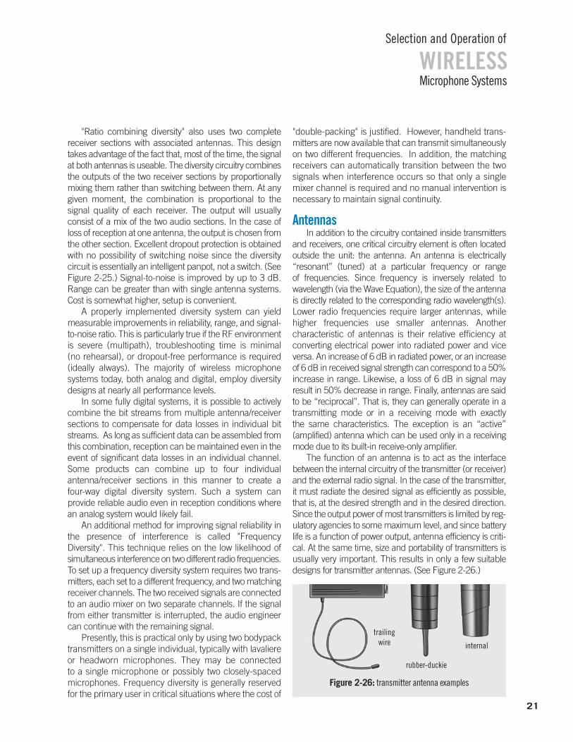
AntennasIn addition to the circuitry contained inside transmitters
and receivers, one critical circuitry element is often locatedoutside the unit: the antenna. An antenna is electrically “resonant” (tuned) at a particular frequency or range of frequencies. Since frequency is inversely related to wavelength (via the Wave Equation), the size of the antennais directly related to the corresponding radio wavelength(s).Lower radio frequencies require larger antennas, whilehigher frequencies use smaller antennas. Another characteristic of antennas is their relative efficiency at converting electrical power into radiated power and viceversa. An increase of 6 dB in radiated power, or an increaseof 6 dB in received signal strength can correspond to a 50%increase in range. Likewise, a loss of 6 dB in signal may result in 50% decrease in range. Finally, antennas are saidto be “reciprocal”. That is, they can generally operate in atransmitting mode or in a receiving mode with exactly the same characteristics. The exception is an “active” (amplified) antenna which can be used only in a receivingmode due to its built-in receive-only amplifier.
The function of an antenna is to act as the interface between the internal circuitry of the transmitter (or receiver)and the external radio signal. In the case of the transmitter,it must radiate the desired signal as efficiently as possible,that is, at the desired strength and in the desired direction.Since the output power of most transmitters is limited by reg-ulatory agencies to some maximum level, and since batterylife is a function of power output, antenna efficiency is criti-cal. At the same time, size and portability of transmitters isusually very important. This results in only a few suitable designs for transmitter antennas. (See Figure 2-26.)
21
WIRELESSSelection and Operation of
Microphone Systems
Figure 2-26: transmitter antenna examples
internal
rubber-duckie
trailingwire
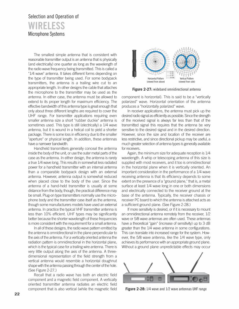
The smallest simple antenna that is consistent with reasonable transmitter output is an antenna that is physically(and electrically) one quarter as long as the wavelength ofthe radio wave frequency being transmitted. This is called a"1/4 wave" antenna. It takes different forms depending onthe type of transmitter being used. For some bodypacktransmitters, the antenna is a trailing wire cut to an appropriate length. In other designs the cable that attachesthe microphone to the transmitter may be used as the antenna. In either case, the antenna must be allowed to extend to its proper length for maximum efficiency. The effective bandwidth of this antenna type is great enough thatonly about three different lengths are required to cover theUHF range. For transmitter applications requiring evensmaller antenna size a short "rubber duckie" antenna issometimes used. This type is still (electrically) a 1/4 waveantenna, but it is wound in a helical coil to yield a shorterpackage. There is some loss in efficiency due to the smaller"aperture" or physical length. In addition, these antennashave a narrower bandwidth.
Handheld transmitters generally conceal the antenna inside the body of the unit, or use the outer metal parts of thecase as the antenna. In either design, the antenna is rarelya true 1/4 wave long. This results in somewhat less radiatedpower for a handheld transmitter with an internal antennathan a comparable bodypack design with an external antenna. However, antenna output is somewhat reducedwhen placed close to the body of the user. Since the antenna of a hand-held transmitter is usually at some distance from the body, though, the practical difference maybe small. Plug-on type transmitters normally use the micro-phone body and the transmitter case itself as the antenna,though some manufacturers models have used an externalantenna. In practice the typical VHF transmitter antenna isless than 10% efficient. UHF types may be significantly better because the shorter wavelength of these frequenciesis more consistent with the requirement for a small antenna.
In all of these designs, the radio wave pattern emitted bythe antenna is omnidirectional in the plane perpendicular tothe axis of the antenna. For a vertically oriented antenna theradiation pattern is omnidirectional in the horizontal plane,which is the typical case for a trailing wire antenna. There isvery little output along the axis of the antenna. A three-dimensional representation of the field strength from a vertical antenna would resemble a horizontal doughnutshape with the antenna passing through the center of the hole.(See Figure 2-27.)
Recall that a radio wave has both an electric field component and a magnetic field component. A verticallyoriented transmitter antenna radiates an electric field component that is also vertical (while the magnetic field
component is horizontal). This is said to be a "vertically polarized" wave. Horizontal orientation of the antenna produces a "horizontally polarized" wave.
In receiver applications, the antenna must pick up the desired radio signal as efficiently as possible. Since the strengthof the received signal is always far less than that of the transmitted signal this requires that the antenna be very sensitive to the desired signal and in the desired direction.However, since the size and location of the receiver are less restrictive, and since directional pickup may be useful, amuch greater selection of antenna types is generally availablefor receivers.
Again, the minimum size for adequate reception is 1/4wavelength. A whip or telescoping antenna of this size issupplied with most receivers, and it too is omnidirectionalin the horizontal plane when it is vertically oriented. An important consideration in the performance of a 1/4 wavereceiving antenna is that its efficiency depends to someextent on the presence of a "ground plane," that is, a metalsurface at least 1/4 wave long in one or both dimensionsand electrically connected to the receiver ground at thebase of the antenna. Typically, the receiver chassis or receiver PC board to which the antenna is attached acts asa sufficient ground plane. (See Figure 2-28.)
If more sensitivity is desired, or if it is necessary to mountan omnidirectional antenna remotely from the receiver, 1/2wave or 5/8 wave antennas are often used. These antennashave a theoretical "gain" (increase of sensitivity) up to 3 dBgreater than the 1/4 wave antenna in some configurations.This can translate into increased range for the system. How-ever, the 5/8 wave antenna, like the 1/4 wave type, onlyachieves its performance with an appropriate ground plane.Without a ground plane unpredictable effects may occur
WIRELESSSelection and Operation of
Microphone Systems
22Figure 2-28: 1/4 wave and 1/2 wave antennas UHF range
Horizontal Pattern(viewed from above)
Vertical Pattern(viewed from side)
Horizontal Pattern(viewed from above)
Vertical Pattern(viewed from side)
Figure 2-27: wideband omnidirectional antenna
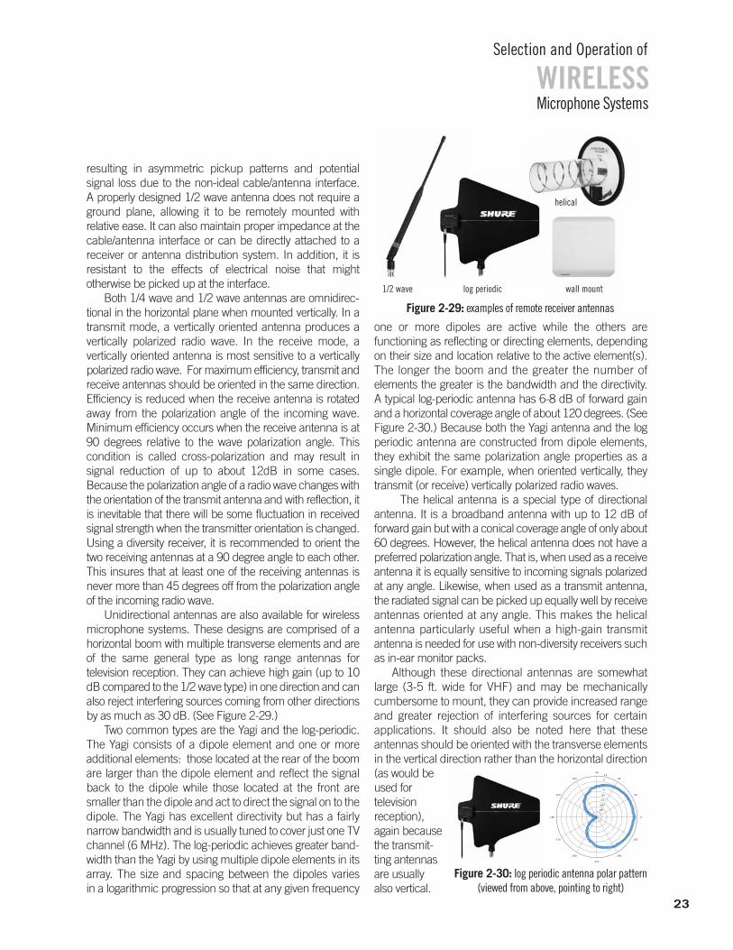
WIRELESSSelection and Operation of
Microphone Systems
resulting in asymmetric pickup patterns and potential signal loss due to the non-ideal cable/antenna interface. A properly designed 1/2 wave antenna does not require aground plane, allowing it to be remotely mounted with relative ease. It can also maintain proper impedance at thecable/antenna interface or can be directly attached to a receiver or antenna distribution system. In addition, it is resistant to the effects of electrical noise that might otherwise be picked up at the interface.
Both 1/4 wave and 1/2 wave antennas are omnidirec-tional in the horizontal plane when mounted vertically. In atransmit mode, a vertically oriented antenna produces a vertically polarized radio wave. In the receive mode, a vertically oriented antenna is most sensitive to a vertically polarized radio wave. For maximum efficiency, transmit andreceive antennas should be oriented in the same direction.Efficiency is reduced when the receive antenna is rotatedaway from the polarization angle of the incoming wave. Minimum efficiency occurs when the receive antenna is at90 degrees relative to the wave polarization angle. This condition is called cross-polarization and may result in signal reduction of up to about 12dB in some cases. Because the polarization angle of a radio wave changes withthe orientation of the transmit antenna and with reflection, itis inevitable that there will be some fluctuation in receivedsignal strength when the transmitter orientation is changed.Using a diversity receiver, it is recommended to orient thetwo receiving antennas at a 90 degree angle to each other.This insures that at least one of the receiving antennas isnever more than 45 degrees off from the polarization angleof the incoming radio wave.
Unidirectional antennas are also available for wirelessmicrophone systems. These designs are comprised of a horizontal boom with multiple transverse elements and areof the same general type as long range antennas for television reception. They can achieve high gain (up to 10dB compared to the 1/2 wave type) in one direction and canalso reject interfering sources coming from other directionsby as much as 30 dB. (See Figure 2-29.)
Two common types are the Yagi and the log-periodic.The Yagi consists of a dipole element and one or moreadditional elements: those located at the rear of the boomare larger than the dipole element and reflect the signalback to the dipole while those located at the front aresmaller than the dipole and act to direct the signal on to thedipole. The Yagi has excellent directivity but has a fairly narrow bandwidth and is usually tuned to cover just one TVchannel (6 MHz). The log-periodic achieves greater band-width than the Yagi by using multiple dipole elements in itsarray. The size and spacing between the dipoles varies in a logarithmic progression so that at any given frequency
one or more dipoles are active while the others are functioning as reflecting or directing elements, dependingon their size and location relative to the active element(s).The longer the boom and the greater the number ofelements the greater is the bandwidth and the directivity. A typical log-periodic antenna has 6-8 dB of forward gainand a horizontal coverage angle of about 120 degrees. (SeeFigure 2-30.) Because both the Yagi antenna and the logperiodic antenna are constructed from dipole elements,they exhibit the same polarization angle properties as a single dipole. For example, when oriented vertically, theytransmit (or receive) vertically polarized radio waves.
The helical antenna is a special type of directional antenna. It is a broadband antenna with up to 12 dB of forward gain but with a conical coverage angle of only about60 degrees. However, the helical antenna does not have a preferred polarization angle. That is, when used as a receiveantenna it is equally sensitive to incoming signals polarizedat any angle. Likewise, when used as a transmit antenna,the radiated signal can be picked up equally well by receive antennas oriented at any angle. This makes the helical antenna particularly useful when a high-gain transmit antenna is needed for use with non-diversity receivers suchas in-ear monitor packs.
Although these directional antennas are somewhatlarge (3-5 ft. wide for VHF) and may be mechanically cumbersome to mount, they can provide increased rangeand greater rejection of interfering sources for certain applications. It should also be noted here that these antennas should be oriented with the transverse elementsin the vertical direction rather than the horizontal direction(as would beused for television reception),again becausethe transmit-ting antennasare usuallyalso vertical.
-25
-20
-15
-10
-5
0
5
10
30
210
60
240
90
270
120
300
150
330
180 0
23
wall mountlog periodic1/2 wave
helical
Figure 2-30: log periodic antenna polar pattern (viewed from above, pointing to right)
Figure 2-29: examples of remote receiver antennas
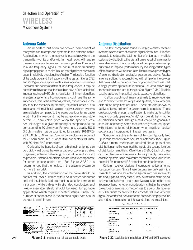
WIRELESSSelection and Operation of
Microphone Systems
Antenna CableAn important but often overlooked component of
many wireless microphone systems is the antenna cable. Applications in which the receiver is located away from thetransmitter vicinity and/or within metal racks will requirethe use of remote antennas and connecting cables. Comparedto audio frequency signals, the nature of radio frequency signal propagation in cables is such that significant losses canoccur in relatively short lengths of cable. The loss is a functionof the cable type and the frequency of the signal. Figures 2-31and 2-32 give some approximate losses for various commonlyused antenna cables at different radio frequencies. It may benoted from this chart that these cables have a "characteristic"impedance, typically 50 ohms. Ideally, for minimum signal lossin antenna systems, all components should have the sameimpedance: that is the antennas, cables, connectors and theinputs of the receivers. In practice, the actual losses due to impedance mismatches in wireless receiver antenna systemsare negligible compared to the losses due to antenna cablelength. For this reason, it may be acceptable to substitutecertain 75 ohm cable types when the specified loss-per-unit-length at a given frequency is comparable to thecorresponding 50 ohm type. For example, a quality RG-6(75 ohm) cable may be substituted for a similar RG-8/RG-213 (50 ohm). Note that 75 ohm connectors are requiredfor 75 ohm cable, but 75 ohm BNC connectors will matewith 50 ohm BNC connectors.
Obviously, the benefits of even a high gain antenna canbe quickly lost using the wrong cable or too long a cable. In general, antenna cable lengths should be kept as shortas possible. Antenna amplifiers can be used to compensatefor losses in long cable runs. (See Figure 2-36.) It is recommended that the net loss in the antenna system beno more than 5dB.
In addition, the construction of the cable should be considered: coaxial cables with a solid center conductor and stiff insulator/shield are most suitable for permanent installation, while cables with stranded conductors andflexible insulator/ shield should be used for portable applications which require repeated setups. Finally, thenumber of connections in the antenna signal path shouldbe kept to a minimum.
Antenna DistributionThe last component found in larger wireless receiver
systems is some form of antenna signal distribution. It is oftendesirable to reduce the total number of antennas in multiplesystems by distributing the signal from one set of antennas toseveral receivers. This is usually done to simplify system setup,but can also improve performance by reducing certain typesof interference as will be seen later. There are two general typesof antenna distribution available: passive and active. Passiveantenna splitting is accomplished with simple in-line devicesthat provide RF impedance matching for minimum loss. Still,a single passive split results in about a 3 dB loss, which maytranslate into some loss of range. (See Figure 2-34.) Multiplepassive splits are impractical due to excessive signal loss.
To allow coupling of antenna signals to more receivers and to overcome the loss of passive splitters, active antennadistribution amplifiers are used. These are also known as"active antenna splitters" or "antenna multi-couplers." Thesedevices provide enough amplification to make up for splitterloss, and usually operate at “unity” gain overall, that is, no netamplification occurs. Though a multi-coupler is generally aseparate accessory, some receiver designs are equippedwith internal antenna distribution when multiple receiversections are incorporated in the same chassis.
Stand-alone active antenna splitters can typically feedup to four receivers from one set of antennas. (See Figure 2-35a.) If more receivers are required, the outputs of onedistribution amplifier can feed the inputs of a second level setof distribution amplifiers. (See Figure 2-35b.) Each of thesecan then feed several receivers. Two or possibly three levelsof active splitters is the maximum recommended, due to thepotential for increased RF distortion and interference.
Certain receiver designs incorporate active antenna "cascade" outputs. Since these outputs are unity gain, it is possible to cascade the antenna signals from one receiver tothe next, up to as many as ten units. A limitation of the typical"daisy chain" scheme is that all receivers must be in the samefrequency band. Another consideration is that in the event ofpower loss or antenna connection loss to a particular receiver,all subsequent receivers in the cascade will lose antenna signal. Nevertheless, active cascade ports can simplify hookupand reduce the requirement for stand-alone active splitters.
24 Figure 2-32: coaxial antenna cable loss at VHF and UHF frequenciesFigure 2-31: comparison of coaxial cable types
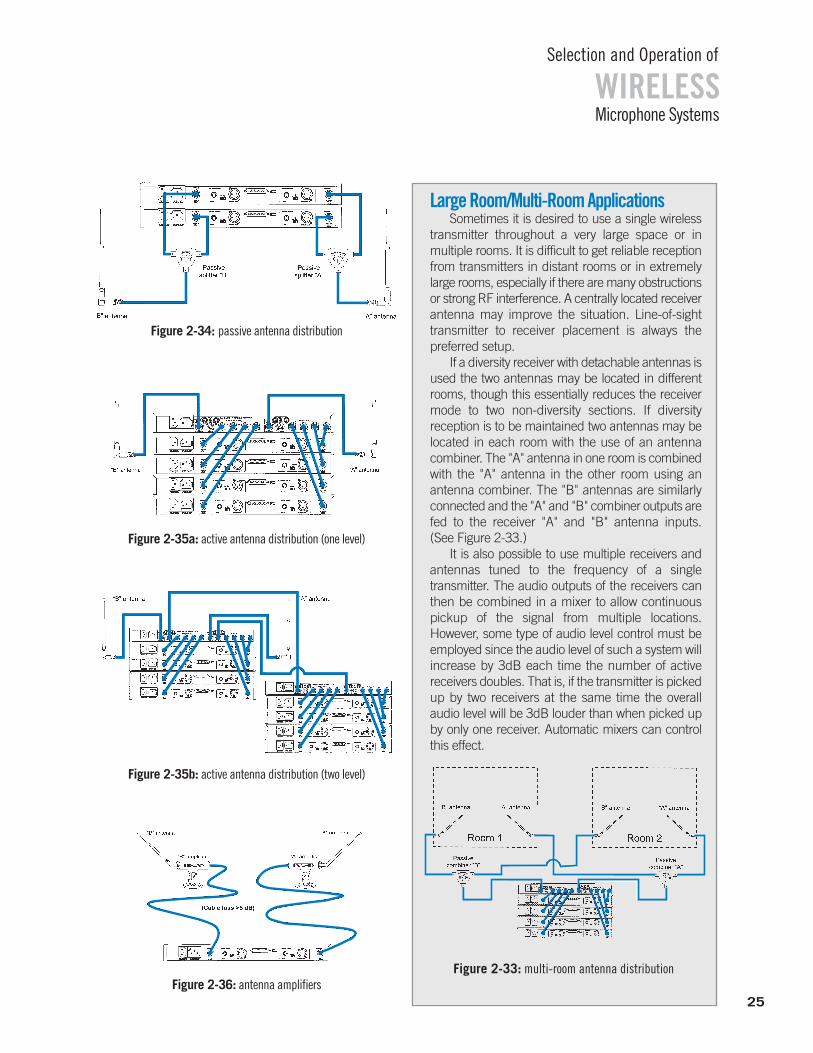
WIRELESSSelection and Operation of
Microphone Systems
Figure 2-35b: active antenna distribution (two level)
Figure 2-35a: active antenna distribution (one level)
Figure 2-34: passive antenna distribution
Figure 2-36: antenna amplifiers
Large Room/Multi-Room ApplicationsSometimes it is desired to use a single wireless
transmitter throughout a very large space or in multiple rooms. It is difficult to get reliable receptionfrom transmitters in distant rooms or in extremelylarge rooms, especially if there are many obstructionsor strong RF interference. A centrally located receiverantenna may improve the situation. Line-of-sighttransmitter to receiver placement is always the preferred setup.
If a diversity receiver with detachable antennas isused the two antennas may be located in differentrooms, though this essentially reduces the receivermode to two non-diversity sections. If diversity reception is to be maintained two antennas may belocated in each room with the use of an antennacombiner. The "A" antenna in one room is combinedwith the "A" antenna in the other room using an antenna combiner. The "B" antennas are similarlyconnected and the "A" and "B" combiner outputs arefed to the receiver "A" and "B" antenna inputs. (See Figure 2-33.)
It is also possible to use multiple receivers and antennas tuned to the frequency of a single transmitter. The audio outputs of the receivers canthen be combined in a mixer to allow continuouspickup of the signal from multiple locations. However, some type of audio level control must beemployed since the audio level of such a system willincrease by 3dB each time the number of active receivers doubles. That is, if the transmitter is pickedup by two receivers at the same time the overallaudio level will be 3dB louder than when picked upby only one receiver. Automatic mixers can controlthis effect.
Figure 2-33: multi-room antenna distribution
25
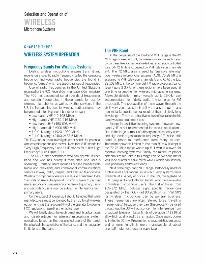
26
WIRELESSSelection and Operation of
Microphone Systems
CHAPTER THREE
WIRELESS SYSTEM OPERATION
Frequency Bands For Wireless SystemsExisting wireless microphone systems transmit and
receive on a specific radio frequency, called the operatingfrequency. Individual radio frequencies are found in frequency "bands" which are specific ranges of frequencies.
Use of radio frequencies in the United States isregulated by the FCC (Federal Communications Commission).The FCC has designated certain bands of frequenciesand certain frequencies in those bands for use by wireless microphones, as well as by other services. In theUS, the frequencies used for wireless audio systems maybe grouped into six general bands or ranges:
• Low-band VHF (49-108 MHz)• High-band VHF (169-216 MHz)• Low-band UHF (450-698 MHz)• High-band UHF (900-952 MHz)• 1.9 GHz range (1920-1930 MHz)• 2.4 GHz range (2400-2483.5 MHz)
The FCC continues to investigate other bands for potentialwireless microphone use as well. Note that VHF stands for“Very High Frequency,” and UHF stands for “Ultra HighFrequency.” (See Figure 3-1.)
The FCC further determines who can operate in eachband and who has priority if more than one user is operating. "Primary" users include licensed broadcasters(radio and television) and commercial communicationsservices (2-way radio, pagers, and cellular telephones).Wireless microphone operators are always considered to be"secondary" users. In general, priority is given to primaryusers: secondary users may not interfere with primary users,and secondary users may be subject to interference fromprimary users.
On the subject of licensing, it should be noted that whilemanufacturers must be licensed by the FCC to sell wirelessequipment, it is the responsibility of the operator to observeFCC regulations regarding their actual use.
We will briefly describe each band and its advantagesand disadvantages for wireless microphone system operation, based on the designated users of the band,the physical characteristics of the band, and the regulatorylimitations of the band.
The VHF BandAt the beginning of the low-band VHF range is the 49
MHz region, used not only by wireless microphones but alsoby cordless telephones, walkie-talkies, and radio controlledtoys. 54-72 MHz is occupied by VHF television channels 2-4. The 72 MHz area is used by “assistive listening” type wireless microphone systems (ALS). 76-88 MHz is assigned to VHF television channels 5 and 6. At the top, 88-108 MHz is the commercial FM radio broadcast band.(See Figure 3-3.) All of these regions have been used atone time or another for wireless microphone systems. Allowable deviation limits (typically up to 15KHz) can accommodate high-fidelity audio (the same as for FMbroadcast). The propagation of these waves through theair is very good, as is their ability to pass through manynon-metallic substances (a result of their relatively longwavelength). The most attractive feature of operation in thisband was low equipment cost.
Except for assistive listening systems, however, low-band VHF is not recommended for serious applications.Due to the large number of primary and secondary users,and high levels of general radio frequency (RF) "noise," thisband is prone to interference from many sources. Transmitter power is limited to less than 50 mW (except inthe 72-76 MHz range where up to 1 watt is allowed for assistive listening systems). Finally, the minimum proper antenna size for units in this range can be over one meterlong (one quarter of a five meter wave), which can severelylimit portability and/or efficiency.
Next is the high-band VHF range, historically used forprofessional applications, in which quality systems wereavailable at a variety of prices. In the US, the high-bandVHF range is divided into two bands, which are availableto wireless microphone users. The first of these, from169-172 MHz, includes eight specific frequencies designated by the FCC (Part 90.263b or just "Part 90") for wireless microphone use by general business. These frequencies are often referred to as "travelling frequencies," because they can (theoretically) be usedthroughout the US without concern for interference frombroadcast television. Legal limits of deviation (+/_12 KHz)allow high quality audio transmission. Once again, poweris limited to 50 mw. Propagation characteristics are good,and antenna length is more manageable at about one-half meter for a quarter-wave type.
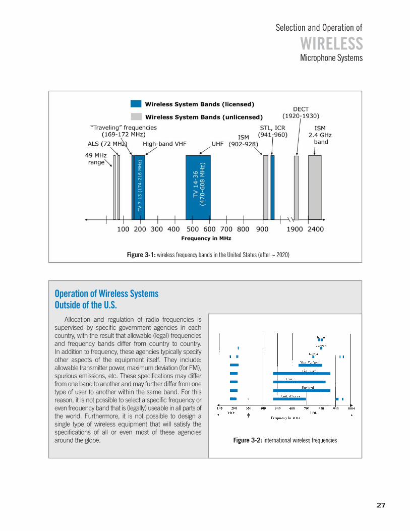
WIRELESSSelection and Operation of
Microphone Systems
Figure 3-1: wireless frequency bands in the United States (after ~ 2020)
27
Figure 3-2: international wireless frequencies
Operation of Wireless SystemsOutside of the U.S.
Allocation and regulation of radio frequencies is supervised by specific government agencies in each country, with the result that allowable (legal) frequenciesand frequency bands differ from country to country. In addition to frequency, these agencies typically specifyother aspects of the equipment itself. They include: allowable transmitter power, maximum deviation (for FM),spurious emissions, etc. These specifications may differfrom one band to another and may further differ from onetype of user to another within the same band. For this reason, it is not possible to select a specific frequency oreven frequency band that is (legally) useable in all parts ofthe world. Furthermore, it is not possible to design a single type of wireless equipment that will satisfy the specifications of all or even most of these agencies around the globe.
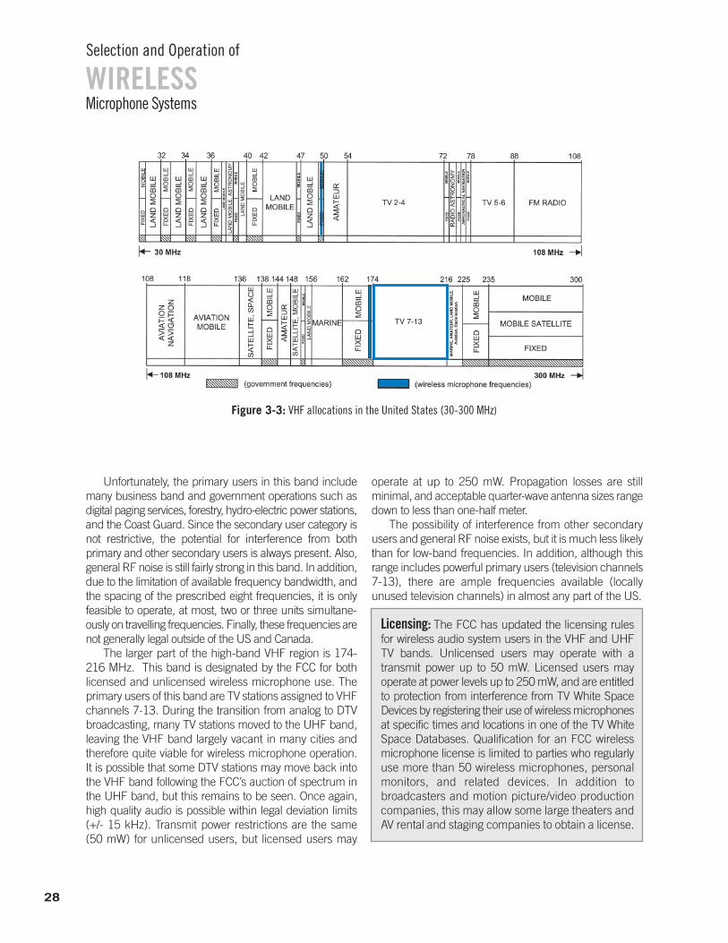
WIRELESSSelection and Operation of
Microphone Systems
28
Unfortunately, the primary users in this band includemany business band and government operations such asdigital paging services, forestry, hydro-electric power stations,and the Coast Guard. Since the secondary user category isnot restrictive, the potential for interference from both primary and other secondary users is always present. Also,general RF noise is still fairly strong in this band. In addition,due to the limitation of available frequency bandwidth, andthe spacing of the prescribed eight frequencies, it is only feasible to operate, at most, two or three units simultane-ously on travelling frequencies. Finally, these frequencies arenot generally legal outside of the US and Canada.
The larger part of the high-band VHF region is 174-216 MHz. This band is designated by the FCC for both licensed and unlicensed wireless microphone use. The primary users of this band are TV stations assigned to VHFchannels 7-13. During the transition from analog to DTVbroadcasting, many TV stations moved to the UHF band,leaving the VHF band largely vacant in many cities andtherefore quite viable for wireless microphone operation.It is possible that some DTV stations may move back intothe VHF band following the FCC’s auction of spectrum inthe UHF band, but this remains to be seen. Once again,high quality audio is possible within legal deviation limits(+/- 15 kHz). Transmit power restrictions are the same (50 mW) for unlicensed users, but licensed users may
operate at up to 250 mW. Propagation losses are still minimal, and acceptable quarter-wave antenna sizes rangedown to less than one-half meter.
The possibility of interference from other secondaryusers and general RF noise exists, but it is much less likelythan for low-band frequencies. In addition, although thisrange includes powerful primary users (television channels7-13), there are ample frequencies available (locally unused television channels) in almost any part of the US.
Licensing: The FCC has updated the licensing rules for wireless audio system users in the VHF and UHFTV bands. Unlicensed users may operate with a transmit power up to 50 mW. Licensed users may operate at power levels up to 250 mW, and are entitled to protection from interference from TV White SpaceDevices by registering their use of wireless microphonesat specific times and locations in one of the TV WhiteSpace Databases. Qualification for an FCC wireless microphone license is limited to parties who regularlyuse more than 50 wireless microphones, personalmonitors, and related devices. In addition to broadcasters and motion picture/video productioncompanies, this may allow some large theaters andAV rental and staging companies to obtain a license.
Figure 3-3: VHF allocations in the United States (30-300 MHz)
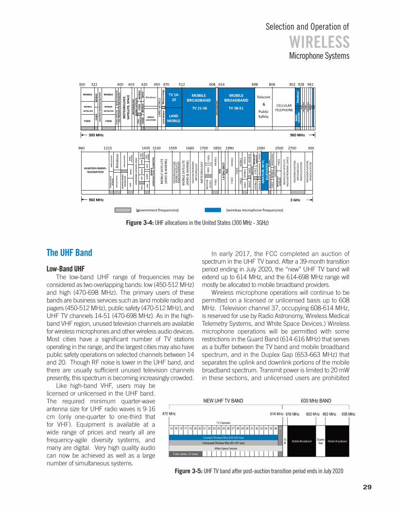
WIRELESSSelection and Operation of
Microphone Systems
The UHF Band
Low-Band UHFThe low-band UHF range of frequencies may be
considered as two overlapping bands: low (450-512 MHz)and high (470-698 MHz). The primary users of thesebands are business services such as land mobile radio andpagers (450-512 MHz), public safety (470-512 MHz), andUHF TV channels 14-51 (470-698 MHz). As in the high-band VHF region, unused television channels are availablefor wireless microphones and other wireless audio devices.Most cities have a significant number of TV stations operating in the range, and the largest cities may also havepublic safety operations on selected channels between 14and 20. Though RF noise is lower in the UHF band, andthere are usually sufficient unused television channelspresently, this spectrum is becoming increasingly crowded.
Like high-band VHF, users may be licensed or unlicensed in the UHF band.The required minimum quarter-wave antenna size for UHF radio waves is 9-16cm (only one-quarter to one-third that for VHF). Equipment is available at a wide range of prices and nearly all are frequency-agile diversity systems, andmany are digital. Very high quality audiocan now be achieved as well as a largenumber of simultaneous systems.
In early 2017, the FCC completed an auction ofspectrum in the UHF TV band. After a 39-month transitionperiod ending in July 2020, the “new” UHF TV band will extend up to 614 MHz, and the 614-698 MHz range willmostly be allocated to mobile broadband providers.
Wireless microphone operations will continue to be permitted on a licensed or unlicensed basis up to 608MHz. (Television channel 37, occupying 608-614 MHz,is reserved for use by Radio Astronomy, Wireless MedicalTelemetry Systems, and White Space Devices.) Wireless microphone operations will be permitted with some restrictions in the Guard Band (614-616 MHz) that servesas a buffer between the TV band and mobile broadband spectrum, and in the Duplex Gap (653-663 MHz) that separates the uplink and downlink portions of the mobilebroadband spectrum. Transmit power is limited to 20 mWin these sections, and unlicensed users are prohibited
608 806 902 941512420403322 400 470300 450 614 928
MOBILE
SATELLITE
300 MHz 960 MHz
CELLULAR TELEPHONETV 38-51TV 38-51TV 21-36TV 21-36
TV 14-TV 14-2020
LAND LAND MOBILEMOBILE
LAN
D M
OBI
LE
LAN
D M
OBI
LE
MOBILE
SATELLITE
FIXEDFIXED
FIXE
D
FIXE
DFI
XED
MOBILEMOBILEM
OBI
LE
MO
BILE
MO
BILE
Amateur
RADIO-LOCATION
RAD
IO A
STRO
NO
MY Am
ateu
rA
mat
eur
RAD
IO-
RAD
IO-
LOCA
TIO
NLO
CATI
ON
AV
IATI
ON
RA
DIO
NA
VIG
ATI
ON
MO
BILE
SA
TELL
ITE
R-N
AV
SA
TELL
ITE
STD
. FRE
QU
ENCY
.& T
IME
SATE
LLIT
E
RAD
IO
AST
RON
OM
Y
MO
BILE
SA
TELL
ITE
MET
EORO
LOG
Y
MET
EORO
LOG
Y,
SATE
LLIT
E, S
PACE Sp
ace
Met
eoro
logy
FIXE
D
LAN
D M
OBI
LE
LAN
D M
OBI
LE
FIXE
D
FIXE
D
FIXE
D
MO
BILE
AVIATION RADIO-NAVIGATION
3 GHz960 MHz
Am
ateu
rA
VIA
TIO
N R
AD
IO-
NA
VIG
ATI
ON
RAD
IOLO
CATI
ON
RAD
IOLO
CATI
ON
RA
DIO
LOCA
TIO
NRA
DIO
LOCA
TIO
N
SATE
LLIT
E
RAD
IO-
LOCA
TIO
NM
OBI
LEFI
XED AST
RON
OM
Y, S
ATE
LLIT
E, S
PACE
MO
BILE
FIXE
DFI
XED
FIXE
DM
OBI
LEFI
XED
SPA
CE
MO
BILE
(A
ERO
NA
UTI
CAL
TELE
MET
RY)
MO
BILE
SA
TELL
ITE
(AER
O &
MA
RIN
E)
RAD
ION
AVI
GA
TIO
N,
MO
BILE
SA
TELL
ITE,
RA
DIO
AST
RON
OM
Y
MO
BILE
SA
TELL
ITE
(AER
O &
MA
RIN
E)
RAD
IOA
STRO
NO
MY,
M
ETEO
ROLO
GY
MET
EORO
LOG
Y
FIXE
D
FIXE
DFI
XED
FIXE
D
FIXE
D
FIXE
D
FIXE
D
FIXE
DFI
XED
MO
BILE
MO
BILE
MO
BILE
MO
BILE
AM
ATE
UR,
WI-F
I, A
MA
TEU
R, W
I-FI,
BLU
ETO
OTH
BLU
ETO
OTH
RAD
ION
AVI
GA
TIO
N,
MET
EORO
LOG
Y,
RAD
IOLO
CATI
ON
RAD
ION
AVI
GA
TIO
N,
RAD
IOLO
CATI
ON
MO
BILE
RAD
IOLO
CATI
ON
Am
ateu
r
BRO
AD
CAST
SA
TELL
ITE,
RA
DIO
AST
RON
OM
Y, S
PACE
RAD
IOLO
CATI
ON
SATE
LLIT
EBR
OA
DCA
ST
SATE
LLIT
E
AM
ATE
UR
BRO
AD
CAST
SA
TELL
ITE
RA
DIO
LOCA
TIO
NFI
XED
MO
BILE
MO
BILE
FIXE
D
SPA
CE
SPA
CEFI
XED
MO
BILE
MET
EOR-
OLO
GY
LAN
D
MO
BILE
LAN
D
MO
BILE
1700 2390960 1215 1435 1530 16601559 2500 2700 3001850 1990
(government frequencies) (wireless microphone frequencies)
698
Telecom
&
Public Safety
Figure 3-5: UHF TV band after post-auction transition period ends in July 2020
29
Figure 3-4: UHF allocations in the United States (300 MHz - 3GHz)
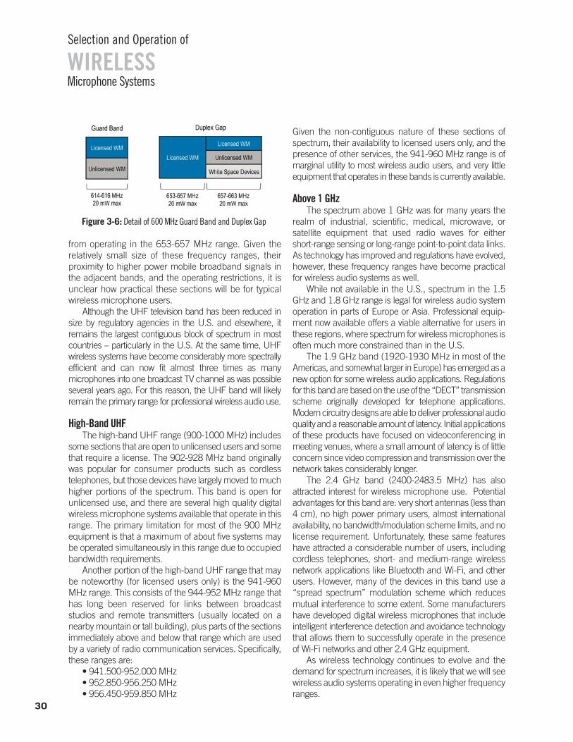
30
WIRELESSSelection and Operation of
Microphone Systems
from operating in the 653-657 MHz range. Given the relatively small size of these frequency ranges, their proximity to higher power mobile broadband signals inthe adjacent bands, and the operating restrictions, it isunclear how practical these sections will be for typicalwireless microphone users.
Although the UHF television band has been reduced insize by regulatory agencies in the U.S. and elsewhere, it remains the largest contiguous block of spectrum in mostcountries – particularly in the U.S. At the same time, UHF wireless systems have become considerably more spectrallyefficient and can now fit almost three times as many microphones into one broadcast TV channel as was possibleseveral years ago. For this reason, the UHF band will likely remain the primary range for professional wireless audio use.
High-Band UHFThe high-band UHF range (900-1000 MHz) includes
some sections that are open to unlicensed users and somethat require a license. The 902-928 MHz band originallywas popular for consumer products such as cordless telephones, but those devices have largely moved to muchhigher portions of the spectrum. This band is open for unlicensed use, and there are several high quality digitalwireless microphone systems available that operate in thisrange. The primary limitation for most of the 900 MHzequipment is that a maximum of about five systems maybe operated simultaneously in this range due to occupiedbandwidth requirements.
Another portion of the high-band UHF range that maybe noteworthy (for licensed users only) is the 941-960MHz range. This consists of the 944-952 MHz range thathas long been reserved for links between broadcast studios and remote transmitters (usually located on anearby mountain or tall building), plus parts of the sectionsimmediately above and below that range which are usedby a variety of radio communication services. Specifically,these ranges are:
• 941.500-952.000 MHz• 952.850-956.250 MHz• 956.450-959.850 MHz
Given the non-contiguous nature of these sections of spectrum, their availability to licensed users only, and the presence of other services, the 941-960 MHz range is of marginal utility to most wireless audio users, and very littleequipment that operates in these bands is currently available.
Above 1 GHzThe spectrum above 1 GHz was for many years the
realm of industrial, scientific, medical, microwave, or satellite equipment that used radio waves for either short-range sensing or long-range point-to-point data links.As technology has improved and regulations have evolved,however, these frequency ranges have become practicalfor wireless audio systems as well.
While not available in the U.S., spectrum in the 1.5GHz and 1.8 GHz range is legal for wireless audio systemoperation in parts of Europe or Asia. Professional equip-ment now available offers a viable alternative for users inthese regions, where spectrum for wireless microphones isoften much more constrained than in the U.S.
The 1.9 GHz band (1920-1930 MHz in most of the Americas, and somewhat larger in Europe) has emerged as anew option for some wireless audio applications. Regulationsfor this band are based on the use of the “DECT” transmissionscheme originally developed for telephone applications. Modern circuitry designs are able to deliver professional audioquality and a reasonable amount of latency. Initial applicationsof these products have focused on videoconferencing in meeting venues, where a small amount of latency is of littleconcern since video compression and transmission over thenetwork takes considerably longer.
The 2.4 GHz band (2400-2483.5 MHz) has also attracted interest for wireless microphone use. Potential advantages for this band are: very short antennas (less than4 cm), no high power primary users, almost internationalavailability, no bandwidth/modulation scheme limits, and nolicense requirement. Unfortunately, these same featureshave attracted a considerable number of users, includingcordless telephones, short- and medium-range wireless network applications like Bluetooth and Wi-Fi, and otherusers. However, many of the devices in this band use a“spread spectrum” modulation scheme which reduces mutual interference to some extent. Some manufacturershave developed digital wireless microphones that include intelligent interference detection and avoidance technologythat allows them to successfully operate in the presence of Wi-Fi networks and other 2.4 GHz equipment.
As wireless technology continues to evolve and the demand for spectrum increases, it is likely that we will seewireless audio systems operating in even higher frequencyranges.
Figure 3-6: Detail of 600 MHz Guard Band and Duplex Gap
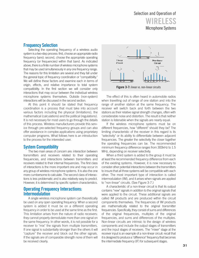
Frequency SelectionSelecting the operating frequency of a wireless audio
system is a two-step process: first, choose an appropriate radiofrequency band; second, choose the appropriate operatingfrequency (or frequencies) within that band. As indicatedabove, there is a finite number of wireless microphone systemsthat may be used simultaneously in any one frequency range.The reasons for this limitation are several and they fall under the general topic of frequency coordination or "compatibility."We will define these factors and examine each in terms of origin, effects, and relative importance to total system compatibility. In the first section we will consider only interactions that may occur between the individual wireless microphone systems themselves. Outside (non-system) interactions will be discussed in the second section.
At this point it should be stated that frequency coordination is a process that must take into account various factors including the physical (limitations), themathematical (calculations) and the political (regulations).It is not necessary for most users to go through the detailsof this process. Wireless manufacturers provide this serv-ice through pre-selected frequency groups and can also offer assistance in complex applications using proprietarycomputer programs. What follows here is an introductionto the process for the interested user.
System CompatibilityThe two main areas of concern are: interaction between
transmitters and receivers related to their operating frequencies, and interactions between transmitters and receivers related to their internal frequencies. The first classof interactions is the more important one and may occur inany group of wireless microphone systems. It is also the onemore cumbersome to calculate. The second class of interac-tions is less problematic and is also relatively easy to predict.However, it is determined by specific system characteristics.
Operating Frequency Interactions:Intermodulation
A single wireless microphone system can theoreticallybe used on any open operating frequency. When a secondsystem is added it must be on a different operating frequency in order to be used at the same time as the first.This limitation arises from the nature of radio receivers:they cannot properly demodulate more than one signal onthe same frequency. In other words, it is not possible for areceiver to "mix" the signals from multiple transmitters. If one signal is substantially stronger than the others it will"capture" the receiver and block out the other signals. If the signals are of comparable strength none of them willbe received clearly.
The effect of this is often heard in automobile radioswhen travelling out of range of one station and into therange of another station at the same frequency. The receiver will switch back and forth between the two stations as their relative signal strength changes, often withconsiderable noise and distortion. The result is that neitherstation is listenable when the signals are nearly equal.
If the wireless microphone systems must be on different frequencies, how "different" should they be? Thelimiting characteristic of the receiver in this regard is its "selectivity" or its ability to differentiate between adjacent frequencies. The greater the selectivity the closer togetherthe operating frequencies can be. The recommended minimum frequency difference ranges from 300kHz to 1.5MHz, depending on receiver selectivity.
When a third system is added to the group it must beat least the recommended frequency difference from eachof the existing systems. However, it is now necessary toconsider other potential interactions between the transmittersto insure that all three systems will be compatible with eachother. The most important type of interaction is called intermodulation (IM), and it arises when signals are appliedto "non-linear" circuits. (See Figure 3-7.)
A characteristic of a non-linear circuit is that its outputcontains "new" signals in addition to the original signals thatwere applied to the circuit. These additional signals arecalled IM products and are produced within the circuit components themselves. The frequencies of IM productsare mathematically related to the original transmitter frequencies. Specifically, they consist of sums and differencesof the original frequencies, multiples of the original frequencies, and sums and differences of the multiples.Non-linear circuits are intrinsic to the design of wireless components and include the output stages of transmittersand the input stages of receivers. The "mixer" stage at the receiver input is an example of a non-linear circuit: recall thatit is designed to produce a "difference" frequency that becomesthe intermediate frequency (IF) for subsequent stages.
31
WIRELESSSelection and Operation of
Microphone Systems
Figure 3-7: linear vs. non-linear circuits
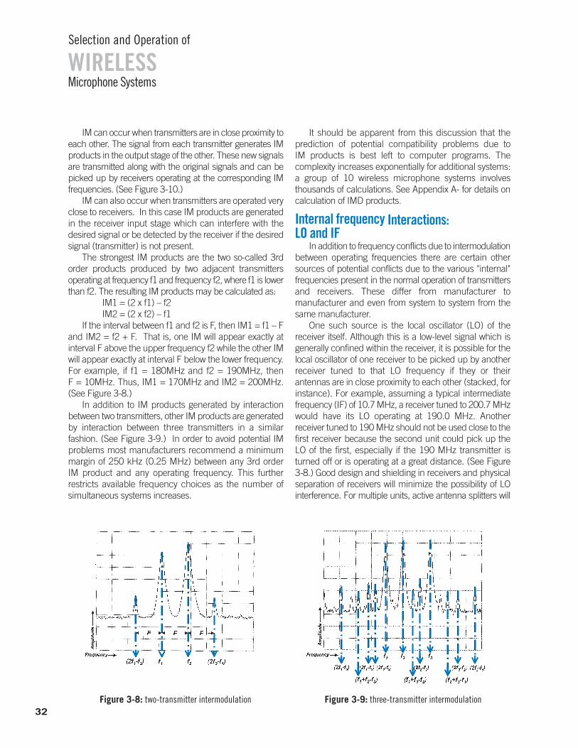
WIRELESSSelection and Operation of
Microphone Systems
IM can occur when transmitters are in close proximity toeach other. The signal from each transmitter generates IMproducts in the output stage of the other. These new signalsare transmitted along with the original signals and can bepicked up by receivers operating at the corresponding IM frequencies. (See Figure 3-10.)
IM can also occur when transmitters are operated veryclose to receivers. In this case IM products are generatedin the receiver input stage which can interfere with the desired signal or be detected by the receiver if the desiredsignal (transmitter) is not present.
The strongest IM products are the two so-called 3rd order products produced by two adjacent transmitters operating at frequency f1 and frequency f2, where f1 is lowerthan f2. The resulting IM products may be calculated as:
IM1 = (2 x f1) – f2 IM2 = (2 x f2) – f1
If the interval between f1 and f2 is F, then IM1 = f1 – Fand IM2 = f2 + F. That is, one IM will appear exactly at interval F above the upper frequency f2 while the other IMwill appear exactly at interval F below the lower frequency.For example, if f1 = 180MHz and f2 = 190MHz, then F = 10MHz. Thus, IM1 = 170MHz and IM2 = 200MHz.(See Figure 3-8.)
In addition to IM products generated by interaction between two transmitters, other IM products are generatedby interaction between three transmitters in a similar fashion. (See Figure 3-9.) In order to avoid potential IMproblems most manufacturers recommend a minimummargin of 250 kHz (0.25 MHz) between any 3rd order IM product and any operating frequency. This further restricts available frequency choices as the number of simultaneous systems increases.
It should be apparent from this discussion that the prediction of potential compatibility problems due to IM products is best left to computer programs. The complexity increases exponentially for additional systems:a group of 10 wireless microphone systems involves thousands of calculations. See Appendix A- for details on calculation of IMD products.
Internal frequency Interactions:LO and IF
In addition to frequency conflicts due to intermodulationbetween operating frequencies there are certain othersources of potential conflicts due to the various "internal" frequencies present in the normal operation of transmittersand receivers. These differ from manufacturer to manufacturer and even from system to system from thesame manufacturer.
One such source is the local oscillator (LO) of the receiver itself. Although this is a low-level signal which is generally confined within the receiver, it is possible for thelocal oscillator of one receiver to be picked up by anotherreceiver tuned to that LO frequency if they or their antennas are in close proximity to each other (stacked, forinstance). For example, assuming a typical intermediatefrequency (IF) of 10.7 MHz, a receiver tuned to 200.7 MHzwould have its LO operating at 190.0 MHz. Another receiver tuned to 190 MHz should not be used close to thefirst receiver because the second unit could pick up theLO of the first, especially if the 190 MHz transmitter isturned off or is operating at a great distance. (See Figure 3-8.) Good design and shielding in receivers and physicalseparation of receivers will minimize the possibility of LO interference. For multiple units, active antenna splitters will
Figure 3-8: two-transmitter intermodulation Figure 3-9: three-transmitter intermodulation32
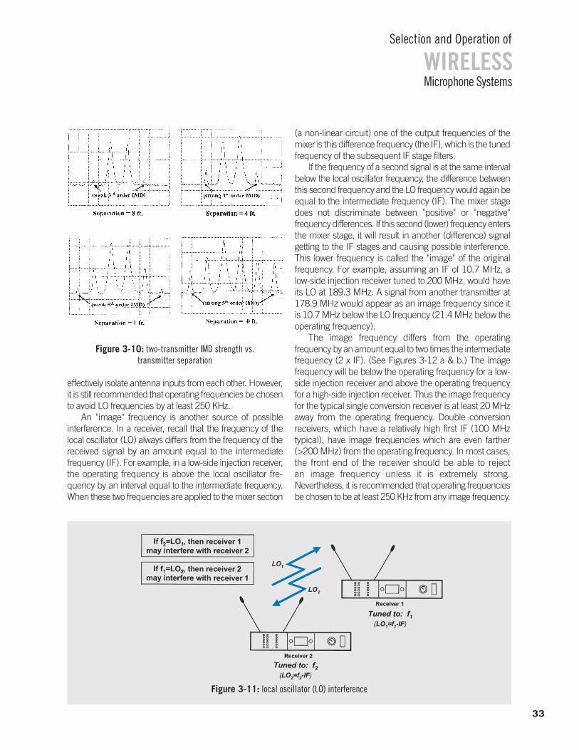
33
WIRELESSSelection and Operation of
Microphone Systems
effectively isolate antenna inputs from each other. However,it is still recommended that operating frequencies be chosento avoid LO frequencies by at least 250 KHz.
An "image" frequency is another source of possible interference. In a receiver, recall that the frequency of thelocal oscillator (LO) always differs from the frequency of thereceived signal by an amount equal to the intermediate frequency (IF). For example, in a low-side injection receiver,the operating frequency is above the local oscillator fre-quency by an interval equal to the intermediate frequency.When these two frequencies are applied to the mixer section
(a non-linear circuit) one of the output frequencies of themixer is this difference frequency (the IF), which is the tunedfrequency of the subsequent IF stage filters.
If the frequency of a second signal is at the same intervalbelow the local oscillator frequency, the difference betweenthis second frequency and the LO frequency would again beequal to the intermediate frequency (IF). The mixer stagedoes not discriminate between "positive" or "negative" frequency differences. If this second (lower) frequency entersthe mixer stage, it will result in another (difference) signal getting to the IF stages and causing possible interference.This lower frequency is called the "image" of the original frequency. For example, assuming an IF of 10.7 MHz, alow-side injection receiver tuned to 200 MHz, would haveits LO at 189.3 MHz. A signal from another transmitter at178.9 MHz would appear as an image frequency since itis 10.7 MHz below the LO frequency (21.4 MHz below theoperating frequency).
The image frequency differs from the operating frequency by an amount equal to two times the intermediatefrequency (2 x IF). (See Figures 3-12 a & b.) The image frequency will be below the operating frequency for a low-side injection receiver and above the operating frequencyfor a high-side injection receiver. Thus the image frequencyfor the typical single conversion receiver is at least 20 MHzaway from the operating frequency. Double conversion receivers, which have a relatively high first IF (100 MHz typical), have image frequencies which are even farther(>200 MHz) from the operating frequency. In most cases,the front end of the receiver should be able to reject an image frequency unless it is extremely strong. Nevertheless, it is recommended that operating frequenciesbe chosen to be at least 250 KHz from any image frequency.
Figure 3-10: two-transmitter IMD strength vs. transmitter separation
Figure 3-11: local oscillator (LO) interference
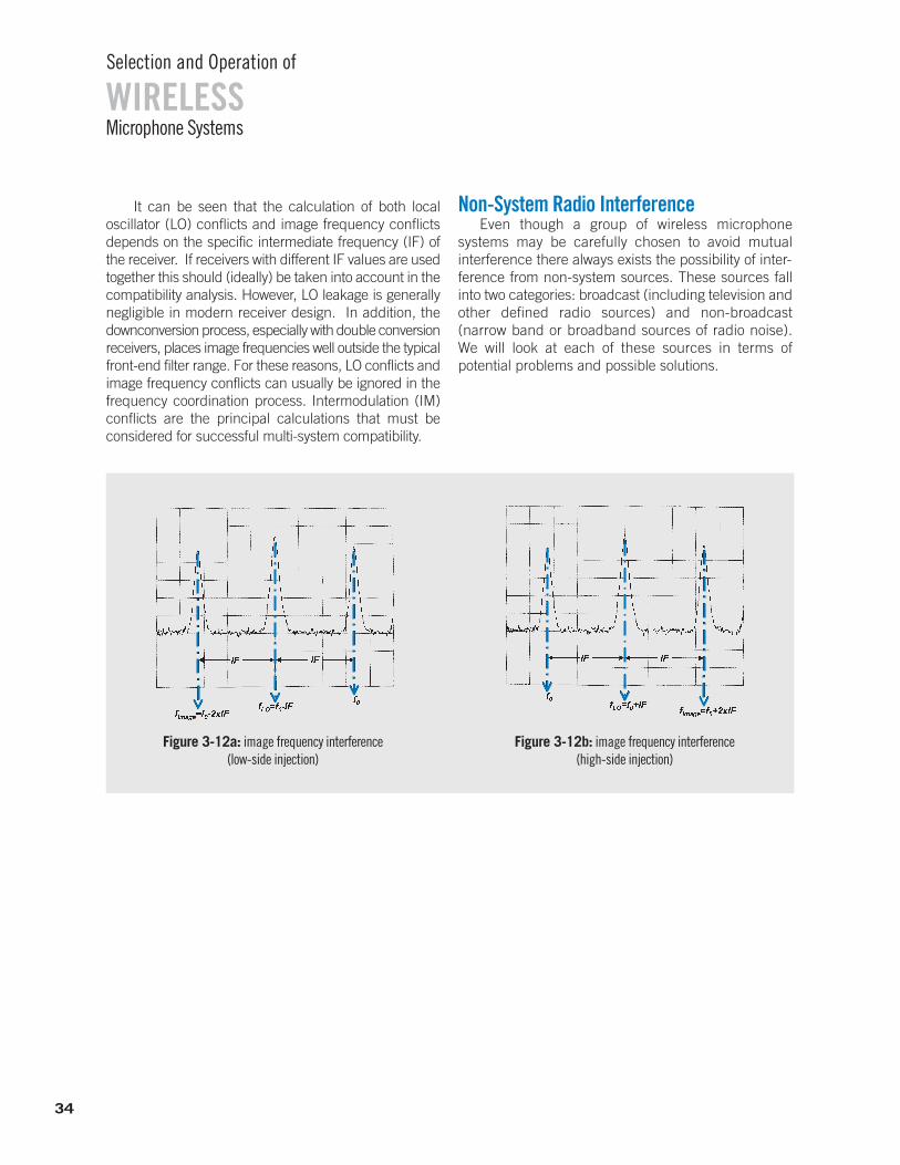
Microphone Systems
Selection and Operation of
WIRELESS
34
It can be seen that the calculation of both local oscillator (LO) conflicts and image frequency conflicts depends on the specific intermediate frequency (IF) ofthe receiver. If receivers with different IF values are usedtogether this should (ideally) be taken into account in thecompatibility analysis. However, LO leakage is generallynegligible in modern receiver design. In addition, thedownconversion process, especially with double conversionreceivers, places image frequencies well outside the typicalfront-end filter range. For these reasons, LO conflicts andimage frequency conflicts can usually be ignored in thefrequency coordination process. Intermodulation (IM)conflicts are the principal calculations that must be considered for successful multi-system compatibility.
Non-System Radio InterferenceEven though a group of wireless microphone
systems may be carefully chosen to avoid mutual interference there always exists the possibility of inter-ference from non-system sources. These sources fallinto two categories: broadcast (including television andother defined radio sources) and non-broadcast (narrow band or broadband sources of radio noise). We will look at each of these sources in terms of potential problems and possible solutions.
Figure 3-12a: image frequency interference (low-side injection)
Figure 3-12b: image frequency interference (high-side injection)
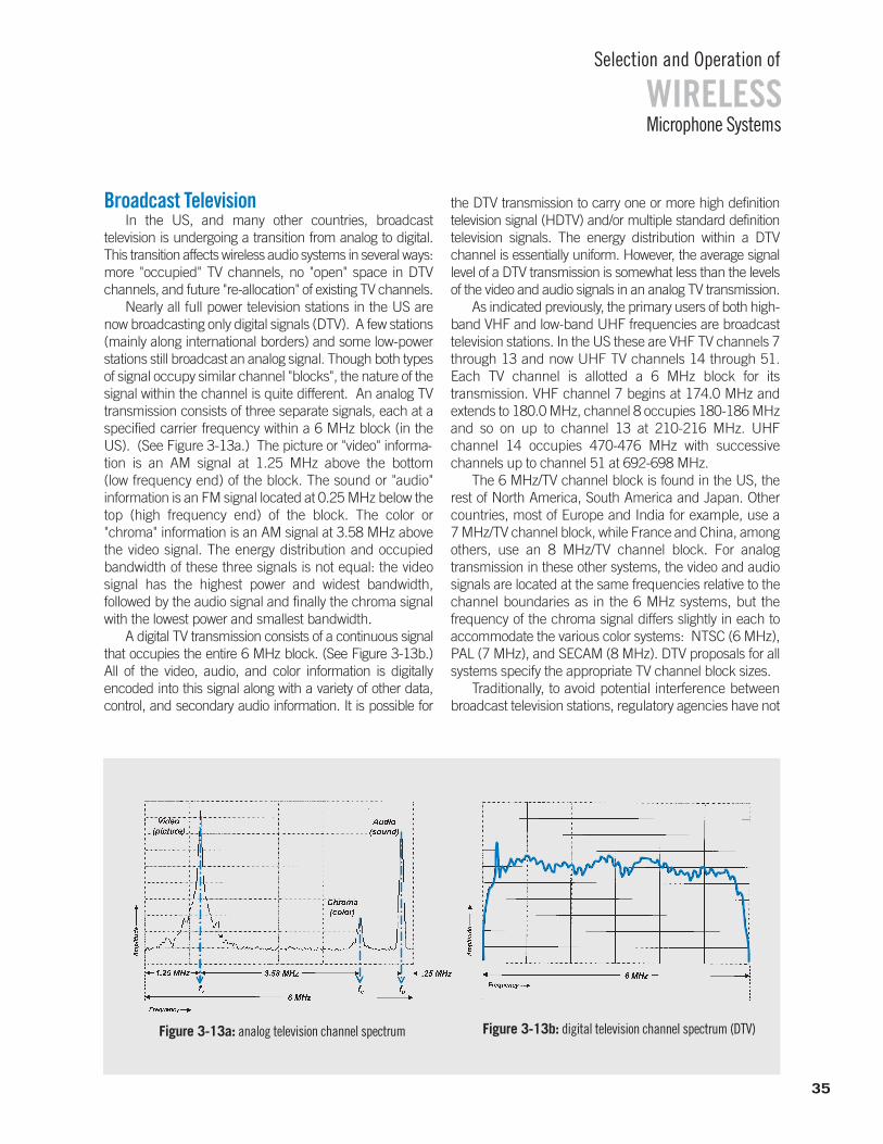
Broadcast TelevisionIn the US, and many other countries, broadcast
television is undergoing a transition from analog to digital.This transition affects wireless audio systems in several ways:more "occupied" TV channels, no "open" space in DTVchannels, and future "re-allocation" of existing TV channels.
Nearly all full power television stations in the US arenow broadcasting only digital signals (DTV). A few stations(mainly along international borders) and some low-powerstations still broadcast an analog signal. Though both typesof signal occupy similar channel "blocks", the nature of thesignal within the channel is quite different. An analog TVtransmission consists of three separate signals, each at aspecified carrier frequency within a 6 MHz block (in theUS). (See Figure 3-13a.) The picture or "video" informa-tion is an AM signal at 1.25 MHz above the bottom (low frequency end) of the block. The sound or "audio" information is an FM signal located at 0.25 MHz below thetop (high frequency end) of the block. The color or"chroma" information is an AM signal at 3.58 MHz abovethe video signal. The energy distribution and occupiedbandwidth of these three signals is not equal: the video signal has the highest power and widest bandwidth, followed by the audio signal and finally the chroma signalwith the lowest power and smallest bandwidth.
A digital TV transmission consists of a continuous signal that occupies the entire 6 MHz block. (See Figure 3-13b.)All of the video, audio, and color information is digitally encoded into this signal along with a variety of other data,control, and secondary audio information. It is possible for
the DTV transmission to carry one or more high definition television signal (HDTV) and/or multiple standard definitiontelevision signals. The energy distribution within a DTV channel is essentially uniform. However, the average signallevel of a DTV transmission is somewhat less than the levelsof the video and audio signals in an analog TV transmission.
As indicated previously, the primary users of both high-band VHF and low-band UHF frequencies are broadcasttelevision stations. In the US these are VHF TV channels 7through 13 and now UHF TV channels 14 through 51.Each TV channel is allotted a 6 MHz block for its transmission. VHF channel 7 begins at 174.0 MHz andextends to 180.0 MHz, channel 8 occupies 180-186 MHzand so on up to channel 13 at 210-216 MHz. UHF channel 14 occupies 470-476 MHz with successive channels up to channel 51 at 692-698 MHz.
The 6 MHz/TV channel block is found in the US, therest of North America, South America and Japan. Othercountries, most of Europe and India for example, use a 7 MHz/TV channel block, while France and China, amongothers, use an 8 MHz/TV channel block. For analog transmission in these other systems, the video and audiosignals are located at the same frequencies relative to thechannel boundaries as in the 6 MHz systems, but the frequency of the chroma signal differs slightly in each toaccommodate the various color systems: NTSC (6 MHz),PAL (7 MHz), and SECAM (8 MHz). DTV proposals for allsystems specify the appropriate TV channel block sizes.
Traditionally, to avoid potential interference betweenbroadcast television stations, regulatory agencies have not
Microphone Systems
Selection and Operation of
WIRELESS
Figure 3-13b: digital television channel spectrum (DTV)Figure 3-13a: analog television channel spectrum
35
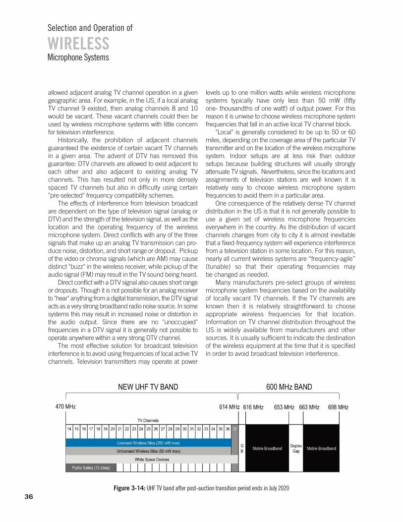
WIRELESSSelection and Operation of
Microphone Systems
allowed adjacent analog TV channel operation in a givengeographic area. For example, in the US, if a local analogTV channel 9 existed, then analog channels 8 and 10would be vacant. These vacant channels could then beused by wireless microphone systems with little concernfor television interference.
Historically, the prohibition of adjacent channels guaranteed the existence of certain vacant TV channels in a given area. The advent of DTV has removed this guarantee: DTV channels are allowed to exist adjacent toeach other and also adjacent to existing analog TV channels. This has resulted not only in more denselyspaced TV channels but also in difficulty using certain "pre-selected" frequency compatibility schemes.
The effects of interference from television broadcastare dependent on the type of television signal (analog orDTV) and the strength of the television signal, as well as thelocation and the operating frequency of the wireless microphone system. Direct conflicts with any of the threesignals that make up an analog TV transmission can pro-duce noise, distortion, and short range or dropout. Pickupof the video or chroma signals (which are AM) may causedistinct "buzz" in the wireless receiver, while pickup of theaudio signal (FM) may result in the TV sound being heard.
Direct conflict with a DTV signal also causes short rangeor dropouts. Though it is not possible for an analog receiverto "hear" anything from a digital transmission, the DTV signalacts as a very strong broadband radio noise source. In somesystems this may result in increased noise or distortion inthe audio output. Since there are no "unoccupied" frequencies in a DTV signal it is generally not possible to operate anywhere within a very strong DTV channel.
The most effective solution for broadcast television interference is to avoid using frequencies of local active TVchannels. Television transmitters may operate at power
levels up to one million watts while wireless microphonesystems typically have only less than 50 mW (fifty one- thousandths of one watt!) of output power. For thisreason it is unwise to choose wireless microphone systemfrequencies that fall in an active local TV channel block.
"Local" is generally considered to be up to 50 or 60miles, depending on the coverage area of the particular TVtransmitter and on the location of the wireless microphonesystem. Indoor setups are at less risk than outdoor setups because building structures will usually strongly attenuate TV signals. Nevertheless, since the locations andassignments of television stations are well known it is relatively easy to choose wireless microphone system frequencies to avoid them in a particular area.
One consequence of the relatively dense TV channeldistribution in the US is that it is not generally possible touse a given set of wireless microphone frequencies everywhere in the country. As the distribution of vacantchannels changes from city to city it is almost inevitablethat a fixed-frequency system will experience interferencefrom a television station in some location. For this reason,nearly all current wireless systems are “frequency-agile”(tunable) so that their operating frequencies may be changed as needed.
Many manufacturers pre-select groups of wireless microphone system frequencies based on the availabilityof locally vacant TV channels. If the TV channels areknown then it is relatively straightforward to choose appropriate wireless frequencies for that location. Information on TV channel distribution throughout theUS is widely available from manufacturers and othersources. It is usually sufficient to indicate the destinationof the wireless equipment at the time that it is specifiedin order to avoid broadcast television interference.
Figure 3-14: UHF TV band after post-auction transition period ends in July 202036
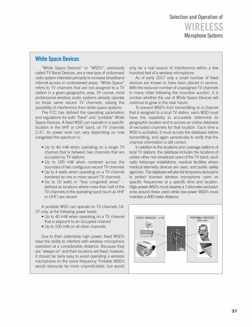
WIRELESSSelection and Operation of
Microphone Systems
37
“White Space Devices” or “WSD’s”, previouslycalled TV Band Devices, are a new type of unlicensedradio system intended primarily to increase broadbandinternet access in underserved areas. “White Space”refers to TV channels that are not assigned to a TV station in a given geographic area. Of course, mostprofessional wireless audio systems already operateon those same vacant TV channels, raising the possibility of interference from white space systems.
The FCC has defined the operating parametersand regulations for both “fixed” and “portable” WhiteSpace Devices. A fixed WSD can operate in a specificlocation in the VHF or UHF band, on TV channels 2-37. Its power level can vary depending on how congested the spectrum is:
• Up to 40 mW when operating on a single TV channel that is between two channels that areoccupied by TV stations
• Up to 100 mW when centered across the boundary of two contiguous vacant TV channels
• Up to 4 watts when operating on a TV channel bordered by one or more vacant TV channels
• Up to 10 watts in “less congested areas” – defined as locations where more than half of theTV channels in the operating band (such as VHFor UHF) are vacant
A portable WSD can operate on TV channels 14-37 only, at the following power levels:
• Up to 40 mW when operating on a TV channelthat is adjacent to an occupied channel
• Up to 100 mW on all other channels
Due to their potentially high power, fixed WSD’shave the ability to interfere with wireless microphoneoperation at a considerable distance. Because theyare “always on” and their locations are fixed, however,it should be fairly easy to avoid operating a wirelessmicrophone on the same frequency. Portable WSD’swould obviously be more unpredictable, but would
only be a real source of interference within a few hundred feet of a wireless microphone.
As of early 2017 only a small number of fixed devices are known to have been placed in service.With the reduced number of unassigned TV channelsin many cities following the incentive auction, it is unclear whether the use of White Space Devices willcontinue to grow in the near future.
To prevent WSD’s from transmitting on a channelthat is assigned to a local TV station, each WSD musthave the capability to accurately determine its geographic location and to access an online databaseof excluded channels for that location. Each time aWSD is activated, it must access the database beforetransmitting, and again periodically to verify that thechannel information is still correct.
In addition to the locations and coverage patterns oflocal TV stations, the database includes the locations ofcertain other non-broadcast users of the TV band, suchradio telescope installations, medical facilities wheremedical telemetry devices are used, and public safetyagencies. The database will also list temporary exclusionsto protect licensed wireless microphone users on specific frequencies at a specific time and location. High-power WSD’s must observe a 1 kilometer exclusionzone around these users while low-power WSD’s mustmaintain a 400 meter distance.
White Space Devices
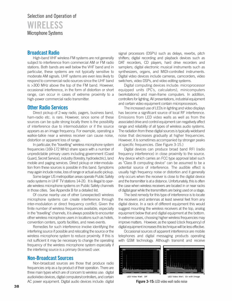
38
WIRELESSSelection and Operation of
Microphone Systems
Broadcast RadioHigh-band VHF wireless FM systems are not generally
subject to interference from commercial AM or FM radiostations. Both bands are well below the VHF band and inparticular, these systems are not typically sensitive to moderate AM signals. UHF systems are even less likely torespond to commercial radio sources since the UHF bandis >300 MHz above the top of the FM band. However, occasional interference, in the form of distortion or shortrange, can occur in cases of extreme proximity to a high-power commercial radio transmitter.
Other Radio ServicesDirect pickup of 2-way radio, pagers, business band,
ham-radio etc. is rare. However, since some of thesesources can be quite strong locally there is the possibilityof interference due to intermodulation or if the source appears as an image frequency. For example, operating awalkie-talkie near a wireless receiver can cause noise, distortion or apparent loss of range.
In particular, the "travelling" wireless microphone systemfrequencies (169-172 MHz) share space with a number ofunpredictable primary users including government (CoastGuard, Secret Service), industry (forestry, hydroelectric), landmobile and paging services. Direct pickup or inter-modula-tion from these sources is possible in this band. Symptomsmay again include noise, loss of range or actual audio pickup.
Some larger US metropolitan areas operate Public Safetyradio systems in UHF TV stations 14-20. It is illegal to oper-ate wireless microphone systems on Public Safety channelsin those cities. See Appendix B for a detailed list.
Of course nearby use of other (unexpected) wirelessmicrophone systems can create interference through inter-modulation or direct frequency conflict. Given the finite number of wireless frequencies available, especiallyin the "travelling" channels, it is always possible to encounterother wireless microphone users in locations such as hotels,convention centers, sports facilities, and news events.
Remedies for such interference involve identifying theinterfering source if possible and relocating the source or thewireless microphone system to reduce proximity. If this isnot sufficient it may be necessary to change the operatingfrequency of the wireless microphone system especially ifthe interfering source is a primary (licensed) user.
Non-Broadcast SourcesNon-broadcast sources are those that produce radio
frequencies only as a by-product of their operation. There arethree main types which are of concern to wireless use: digitalaudio/video devices, digital computers/controllers, and certainAC power equipment. Digital audio devices include: digital
signal processors (DSP’s) such as delays, reverbs, pitchshifters; digital recording and playback devices such as DAT recorders, CD players, hard drive recorders andsamplers; digital electronic musical instruments such assynthesizers, organs, and MIDI-controlled instruments. Digital video devices include cameras, camcorders, videoswitchers, video DSPs, and video editing systems.
Digital computing devices include: microprocessorequipped units (PC’s, calculators), minicomputers(workstations) and main-frame computers. In addition, controllers for lighting, AV presentations, industrial equipmentand certain video equipment contain microprocessors.
The increased use of LEDs in lighting and video displayshas become a significant source of local RF interference.Emissions from LED video walls as well as from the associated drive and control equipment can negatively affectrange and reliability of all types of wireless audio systems.The radiation from these digital sources is typically widebandnoise that decreases gradually at higher frequencies. However, it is sometimes accompanied by stronger peaks at specific frequencies. (See Figure 3-15.)
Digital devices can produce broad band RFI (radio frequency interference) in close proximity to the source. Any device which carries an FCC type approval label suchas "Class B computing device" can be assumed to be a potential source of interference. The audible effect is usually high frequency noise or distortion and it generallyonly occurs when the receiver is close to the digital deviceand the transmitter is at a distance. Unfortunately, this is oftenthe case when wireless receivers are located in or near racksof digital gear while the transmitters are being used on a stage.
The best remedy for this type of interference is to locatethe receivers and antennas at least several feet from any digital device. In a rack of different equipment this wouldsuggest mounting the wireless receivers at the top, analogequipment below that and digital equipment at the bottom.In extreme cases, choosing higher wireless frequencies mayimprove matters. However, as the speed (clock frequency) ofdigital equipment increases this technique will be less effective.
Occasional sources of apparent interference are mobiletelephones and digital messaging products operating with GSM technology. Although transmit and receive
Figure 3-15: LED video wall radio noise
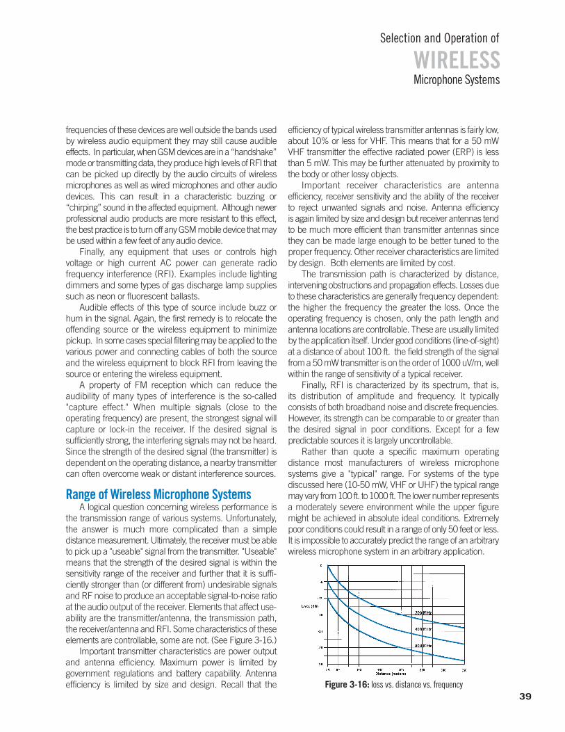
39
WIRELESSSelection and Operation of
Microphone Systems
frequencies of these devices are well outside the bands usedby wireless audio equipment they may still cause audible effects. In particular, when GSM devices are in a “handshake”mode or transmitting data, they produce high levels of RFI thatcan be picked up directly by the audio circuits of wireless microphones as well as wired microphones and other audiodevices. This can result in a characteristic buzzing or “chirping” sound in the affected equipment. Although newerprofessional audio products are more resistant to this effect,the best practice is to turn off any GSM mobile device that may be used within a few feet of any audio device.
Finally, any equipment that uses or controls high voltage or high current AC power can generate radio frequency interference (RFI). Examples include lightingdimmers and some types of gas discharge lamp suppliessuch as neon or fluorescent ballasts.
Audible effects of this type of source include buzz or hum in the signal. Again, the first remedy is to relocate the offending source or the wireless equipment to minimizepickup. In some cases special filtering may be applied to thevarious power and connecting cables of both the sourceand the wireless equipment to block RFI from leaving thesource or entering the wireless equipment.
A property of FM reception which can reduce the audibility of many types of interference is the so-called "capture effect." When multiple signals (close to the operating frequency) are present, the strongest signal willcapture or lock-in the receiver. If the desired signal is sufficiently strong, the interfering signals may not be heard.Since the strength of the desired signal (the transmitter) isdependent on the operating distance, a nearby transmittercan often overcome weak or distant interference sources.
Range of Wireless Microphone SystemsA logical question concerning wireless performance is
the transmission range of various systems. Unfortunately,the answer is much more complicated than a simple distance measurement. Ultimately, the receiver must be ableto pick up a "useable" signal from the transmitter. "Useable"means that the strength of the desired signal is within thesensitivity range of the receiver and further that it is suffi-ciently stronger than (or different from) undesirable signalsand RF noise to produce an acceptable signal-to-noise ratioat the audio output of the receiver. Elements that affect use-ability are the transmitter/antenna, the transmission path,the receiver/antenna and RFI. Some characteristics of theseelements are controllable, some are not. (See Figure 3-16.)
Important transmitter characteristics are power outputand antenna efficiency. Maximum power is limited by government regulations and battery capability. Antenna efficiency is limited by size and design. Recall that the
efficiency of typical wireless transmitter antennas is fairly low,about 10% or less for VHF. This means that for a 50 mWVHF transmitter the effective radiated power (ERP) is lessthan 5 mW. This may be further attenuated by proximity tothe body or other lossy objects.
Important receiver characteristics are antenna efficiency, receiver sensitivity and the ability of the receiver to reject unwanted signals and noise. Antenna efficiency is again limited by size and design but receiver antennas tendto be much more efficient than transmitter antennas since they can be made large enough to be better tuned to theproper frequency. Other receiver characteristics are limitedby design. Both elements are limited by cost.
The transmission path is characterized by distance, intervening obstructions and propagation effects. Losses dueto these characteristics are generally frequency dependent:the higher the frequency the greater the loss. Once the operating frequency is chosen, only the path length and antenna locations are controllable. These are usually limitedby the application itself. Under good conditions (line-of-sight)at a distance of about 100 ft. the field strength of the signalfrom a 50 mW transmitter is on the order of 1000 uV/m, wellwithin the range of sensitivity of a typical receiver.
Finally, RFI is characterized by its spectrum, that is, its distribution of amplitude and frequency. It typically consists of both broadband noise and discrete frequencies.However, its strength can be comparable to or greater thanthe desired signal in poor conditions. Except for a few predictable sources it is largely uncontrollable.
Rather than quote a specific maximum operating distance most manufacturers of wireless microphone systems give a "typical" range. For systems of the type discussed here (10-50 mW, VHF or UHF) the typical rangemay vary from 100 ft. to 1000 ft. The lower number representsa moderately severe environment while the upper figuremight be achieved in absolute ideal conditions. Extremelypoor conditions could result in a range of only 50 feet or less.It is impossible to accurately predict the range of an arbitrarywireless microphone system in an arbitrary application.
Figure 3-16: loss vs. distance vs. frequency

CHAPTER FOUR
WIRELESS SYSTEM SELECTION AND SETUP
System SelectionThe proper selection of a wireless microphone system
consists of several steps based on the intended applicationand on the capabilities and limitations of the equipmentrequired for that application. It should be remembered that while wireless microphone systems cannot ultimatelybe as consistent and reliable as wired systems, the performance of currently available wireless can be verygood, allowing excellent results to be obtained. Followingthese steps will insure selection of the best system(s) for agiven application.
1) Define the application. This definition should includethe intended sound source (voice, instrument, etc.) and theintended sound destination (sound system, recording orbroadcast). It must also include a description of the physicalsetting (architectural and acoustic features). Any special requirements or limitations should also be noted: cosmetics,range, maintenance, other possible sources of RF interference,etc. Finally, the desired performance level must be defined:radio quality, audio quality, and overall reliability.
2) Choose the microphone (or other source) type.The application will usually determine which microphonephysical design is required: a lavaliere or clip-on type attached to clothing, or a head-worn type, both for hands-free use; a handheld type for a vocalist or when themicrophone must be passed around to different users; aconnecting cable when an electric musical instrument orother non-microphone source is used. Other microphonecharacteristics (transducer type, frequency response, anddirectionality) are dictated by acoustic concerns. As mentioned earlier, the microphone choice for a wirelessapplication should be made using the same criteria as fora wired application.
3) Choose the transmitter type. The microphone choicewill usually determine the required transmitter type (hand-held, bodypack or plug-on), again based on the application.General features to consider include: antenna style (internalor external), control functions and location (power, muting,gain, tuning), indicators (power, battery condition), batteries(operating life, type, accessibility), and physical description(size, shape, weight, finish, material). For handheld and plug-on types interchangeability of microphone elements may bean option. For bodypack transmitters, inputs may be hard-wired or detachable. Multi-use inputs are often desirable andmay be characterized by connector type, wiring scheme andelectrical capability (impedance, level, bias voltage, etc.).
4) Choose the receiver type. The basic choice is between diversity and non-diversity. For reasons mentioned in the receiver section above, diversity receiversare recommended for all but the most budget-conscious applications. Though non-diversity types will work well inmany situations, the insurance provided by the diversity receiver against multipath problems is usually well worththe somewhat higher cost. Other receiver features thatshould be considered are: controls (power, output level,squelch, tuning), indicators (power, RF level, audio level,frequency), antennas (type, connectors), electrical outputs(connectors, impedance, line/microphone/headphonelevel, balanced/unbalanced). In some applications batterypower may be required.
5) Determine the total number of systems to be used simultaneously. This should take into account future additions to the system: choosing a system type that canonly accommodate a few frequencies may prove to be aneventual limitation. Of course, the total number should include any existing wireless microphone systems withwhich the new equipment must work.
6) Specify the geographic location in which these systems will be used. This information is necessary in thenext step to avoid possible conflict with broadcast televisionfrequencies. In the case of touring applications, this mayinclude cities inside and outside of the US.
7) Coordinate frequencies for system compatibility andavoidance of known non-system sources. Consult the manufacturer or a knowledgeable professional about frequency selection and integration of the planned numberof systems. This should be done even for single systemsand must certainly be done for any multiple system installation to avoid potential interference problems. Frequency coordination includes the choice of operatingband (VHF and/or UHF) and choice of the individual operating frequencies (for compatibility and avoidance ofother transmissions). For fixed locations choose frequenciesin unused TV channels. For touring applications, it may be necessary to carry additional systems on alternate frequencies, though this is only practical for a small numberof channels. The preferred approach for touring is to use frequency-agile (tunable) units to insure the required number of systems at all venues.
8) Specify accessory equipment as needed. This mayinclude remote antennas (1/2 wave, 5/8 wave, directional),mounting hardware (brackets, ground-planes), antennasplitters (passive, active), and antenna cables (portable,fixed). These choices are dependent on operating frequencies and the individual application.
Microphone Systems
Selection and Operation of
WIRELESS
40
PART TWO: Wireless Microphone Systems: How To Make Them Work
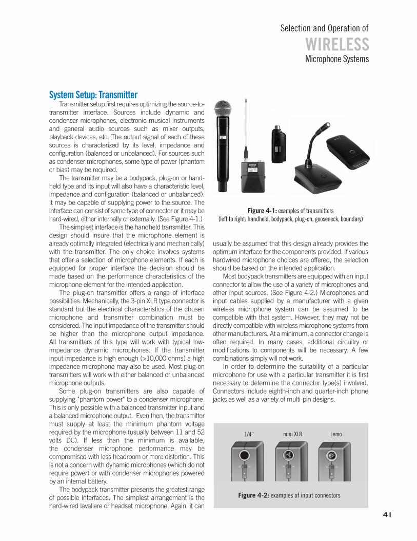
Microphone Systems
Selection and Operation of
WIRELESS
41
System Setup: TransmitterTransmitter setup first requires optimizing the source-to-
transmitter interface. Sources include dynamic and condenser microphones, electronic musical instrumentsand general audio sources such as mixer outputs, playback devices, etc. The output signal of each of thesesources is characterized by its level, impedance and configuration (balanced or unbalanced). For sources suchas condenser microphones, some type of power (phantomor bias) may be required.
The transmitter may be a bodypack, plug-on or hand-held type and its input will also have a characteristic level,impedance and configuration (balanced or unbalanced). It may be capable of supplying power to the source. The interface can consist of some type of connector or it may behard-wired, either internally or externally. (See Figure 4-1.)
The simplest interface is the handheld transmitter. Thisdesign should insure that the microphone element is already optimally integrated (electrically and mechanically)with the transmitter. The only choice involves systems that offer a selection of microphone elements. If each isequipped for proper interface the decision should be made based on the performance characteristics of the microphone element for the intended application.
The plug-on transmitter offers a range of interface possibilities. Mechanically, the 3-pin XLR type connector isstandard but the electrical characteristics of the chosenmicrophone and transmitter combination must be considered. The input impedance of the transmitter shouldbe higher than the microphone output impedance. All transmitters of this type will work with typical low-impedance dynamic microphones. If the transmitter input impedance is high enough (>10,000 ohms) a high impedance microphone may also be used. Most plug-ontransmitters will work with either balanced or unbalancedmicrophone outputs.
Some plug-on transmitters are also capable of supplying "phantom power" to a condenser microphone.This is only possible with a balanced transmitter input anda balanced microphone output. Even then, the transmittermust supply at least the minimum phantom voltage required by the microphone (usually between 11 and 52volts DC). If less than the minimum is available, the condenser microphone performance may be compromised with less headroom or more distortion. Thisis not a concern with dynamic microphones (which do notrequire power) or with condenser microphones poweredby an internal battery.
The bodypack transmitter presents the greatest rangeof possible interfaces. The simplest arrangement is thehard-wired lavaliere or headset microphone. Again, it can
usually be assumed that this design already provides theoptimum interface for the components provided. If varioushardwired microphone choices are offered, the selectionshould be based on the intended application.
Most bodypack transmitters are equipped with an inputconnector to allow the use of a variety of microphones andother input sources. (See Figure 4-2.) Microphones andinput cables supplied by a manufacturer with a given wireless microphone system can be assumed to be compatible with that system. However, they may not be directly compatible with wireless microphone systems fromother manufacturers. At a minimum, a connector change isoften required. In many cases, additional circuitry or modifications to components will be necessary. A few combinations simply will not work.
In order to determine the suitability of a particular microphone for use with a particular transmitter it is firstnecessary to determine the connector type(s) involved.Connectors include eighth-inch and quarter-inch phonejacks as well as a variety of multi-pin designs.
Figure 4-1: examples of transmitters (left to right: handheld, bodypack, plug-on, gooseneck, boundary)
1/4” mini XLR Lemo
Figure 4-2: examples of input connectors
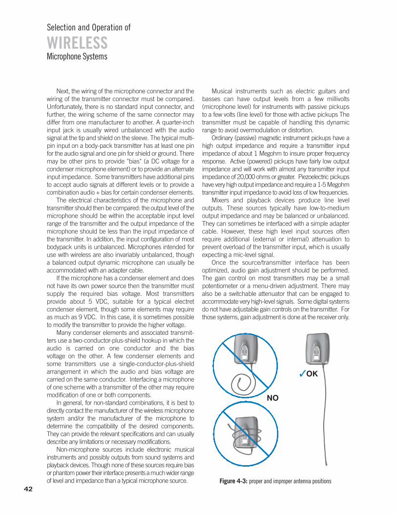
Microphone Systems
Selection and Operation of
WIRELESS
42
Next, the wiring of the microphone connector and thewiring of the transmitter connector must be compared.Unfortunately, there is no standard input connector, andfurther, the wiring scheme of the same connector may differ from one manufacturer to another. A quarter-inchinput jack is usually wired unbalanced with the audio signal at the tip and shield on the sleeve. The typical multi-pin input on a body-pack transmitter has at least one pinfor the audio signal and one pin for shield or ground. Theremay be other pins to provide "bias" (a DC voltage for a condenser microphone element) or to provide an alternateinput impedance. Some transmitters have additional pinsto accept audio signals at different levels or to provide acombination audio + bias for certain condenser elements.
The electrical characteristics of the microphone andtransmitter should then be compared: the output level of themicrophone should be within the acceptable input levelrange of the transmitter and the output impedance of themicrophone should be less than the input impedance of the transmitter. In addition, the input configuration of mostbodypack units is unbalanced. Microphones intended foruse with wireless are also invariably unbalanced, though a balanced output dynamic microphone can usually be accommodated with an adapter cable.
If the microphone has a condenser element and doesnot have its own power source then the transmitter mustsupply the required bias voltage. Most transmitters provide about 5 VDC, suitable for a typical electret condenser element, though some elements may requireas much as 9 VDC. In this case, it is sometimes possibleto modify the transmitter to provide the higher voltage.
Many condenser elements and associated transmit-ters use a two-conductor-plus-shield hookup in which the audio is carried on one conductor and the bias voltage on the other. A few condenser elements and some transmitters use a single-conductor-plus-shield arrangement in which the audio and bias voltage are carried on the same conductor. Interfacing a microphoneof one scheme with a transmitter of the other may requiremodification of one or both components.
In general, for non-standard combinations, it is best to directly contact the manufacturer of the wireless microphonesystem and/or the manufacturer of the microphone to determine the compatibility of the desired components. They can provide the relevant specifications and can usuallydescribe any limitations or necessary modifications.
Non-microphone sources include electronic musical instruments and possibly outputs from sound systems andplayback devices. Though none of these sources require biasor phantom power their interface presents a much wider rangeof level and impedance than a typical microphone source.
Musical instruments such as electric guitars andbasses can have output levels from a few millivolts (microphone level) for instruments with passive pickupsto a few volts (line level) for those with active pickups Thetransmitter must be capable of handling this dynamicrange to avoid overmodulation or distortion.
Ordinary (passive) magnetic instrument pickups have ahigh output impedance and require a transmitter input impedance of about 1 Megohm to insure proper frequencyresponse. Active (powered) pickups have fairly low output impedance and will work with almost any transmitter input impedance of 20,000 ohms or greater. Piezoelectric pickupshave very high output impedance and require a 1-5 Megohmtransmitter input impedance to avoid loss of low frequencies.
Mixers and playback devices produce line level outputs. These sources typically have low-to-medium output impedance and may be balanced or unbalanced.They can sometimes be interfaced with a simple adaptercable. However, these high level input sources often require additional (external or internal) attenuation to prevent overload of the transmitter input, which is usuallyexpecting a mic-level signal.
Once the source/transmitter interface has been optimized, audio gain adjustment should be performed. The gain control on most transmitters may be a small potentiometer or a menu-driven adjustment. There may also be a switchable attenuator that can be engaged to accommodate very high-level signals. Some digital systemsdo not have adjustable gain controls on the transmitter. Forthose systems, gain adjustment is done at the receiver only.
NO
✓OK
Figure 4-3: proper and improper antenna positions

Microphone Systems
Selection and Operation of
WIRELESS
43
The control(s) should be adjusted so that the loudestsound level (or highest instrument level) in actual use produces full modulation of the radio signal. This is usually determined by speaking or singing into the microphone (or playing the instrument) while observingaudio level indicators on the receiver. Typically, an audiopeak LED will indicate full (or nearly full) modulation. A few designs have peak indicators on the transmittersthemselves. In systems that indicate peaks at less thanfull modulation, this LED may light fairly often. For systems that indicate full modulation, this should lightonly briefly at maximum input levels. In either case, sustained peak indication requires reducing input sensitivity or level to avoid audible distortion.
If the transmitter is equipped with a compander system (noise reduction) defeat switch make sure thatit is set to the same mode as the receiver. The only situationin which this system would be defeated is with the useof a receiver that is not equipped with compander circuitry.Non-companded analog wireless systems are used pri-marily for audio measurement purposes.
For tunable transmitters, make sure that the transmitter is set to the same frequency as the receiver.
The last step in transmitter setup is placement. Placement of a handheld or plug-on system is essentiallythe same as for a wired microphone of the same type. Theunit may be mounted on a stand, boom or fishpole withan appropriate stand adapter, or it may be handheld.
Bodypack transmitter placement is dependent on theparticular application. If the input source is a microphone,
such as a lavaliere or headset, the bodypack is normallyclipped to a belt or pants waistband. It may be attached inother ways as long as the antenna is allowed to extend freely.Insure that there is adequate access to the controls if necessary and that the connecting cable, if any, has enoughlength to permit the source and the transmitter to be locatedas desired. When the input is a musical instrument, it is often possible to attach the transmitter directly to the instrument or to its strap as in the case of an electric guitar.
For all types of transmitters, insure that the antenna issecurely attached and positioned for maximum efficiency.Wire antennas should be fully extended. The hand shouldnot cover external antennas on handheld transmitters. (See Figure 4-3.)
As much as possible, proper transmitter placement shouldavoid large metal objects and previously mentioned sourcesof RF such as digital devices, other wireless transmitters and mobile telephones. If an individual is using more than one wireless system at the same time, such as a wireless head-setand a wireless musical instrument, or is wearing a wireless personal monitor receiver, the devices should be kept as farapart as practical to minimize interaction.
System Setup: ReceiversReceiver setup involves two interfaces: antenna-to-
receiver and receiver-to-sound system. (See Figure 4-4.)
Audio InterfaceHere we will discuss the sound system interface.
Remember that the basic function of a wireless microphone system is to replace the connecting cable between the source and the sound system. In the typicalcase, the output of the wireless receiver will resemble the output of the original source both electrically and physically. That is, most wireless microphone receivershave a balanced, low impedance, microphone level output,usually on a standard 3-pin XLR-type audio connector. This can be connected to a standard microphone input ofa sound system using an ordinary balanced microphonecable. (See Figure 4-5.)
Figure 4-4: receiver examples
fixed portable
VHF UHFantenna inputs
audio outputs
Figure 4-5: examples of receiver audio output and antenna input connectors
44
WIRELESSSelection and Operation of
Microphone Systems
Some receivers, particularly those designed for use withelectric instruments, may be equipped with a quarter-inchphone jack instead of (or in addition to) an XLR connector.Normally, this output is an unbalanced, low or medium impedance, microphone or instrument level signal. It canbe directly connected to the input of an instrument amplifier using a standard shielded instrument cable.
In addition, a few receivers have line level outputs available.These can be connected to line or aux level inputs of soundsystems equipped with similar types of input connectors.
If it is desired (or necessary) to connect one type of output to a different type of input a few possibilities shouldbe considered. For a balanced XLR output to an unbalanced quarter-inch input an adapter which connectsPin 2 of the XLR to the tip of the phone plug and connectsPin 1 and Pin 3 of the XLR to the sleeve of the phone plugmay be used. A similar adapter (with appropriate XLR connector) may be used to connect an unbalanced quarter-inch output to a balanced XLR input. Simpleadapters of this type will usually work if the levels and impedances of the outputs and inputs are compatible.
In some cases simple adapters cannot be used due tosignificant impedance or level differences. In addition, thequarter-inch phone-to-XLR hookups just described (whichcause the circuit to be unbalanced) can occasionally create audible hum problems due to ground loops betweenthe receiver and the sound system. In either case, the useof a transformer may offer a solution. It can provide theproper transition between different impedances and between balanced and unbalanced circuits. The transformeralso allows ground loops to be eliminated by lifting the shield connection at the source end of the balanced cable.
Finally, the presence of phantom power at the balanced microphone input of the sound system must beconsidered. If the receiver output is unbalanced, phantompower may cause noise or distortion in the signal. Phantompower should be turned off at that input if possible. If not,a suitable transformer or an adapter with capacitors willblock the voltage in the connecting path. However, if the receiver output is balanced, phantom power is usually nota problem though a manufacturer may specify the maximum voltage that the receiver can tolerate. A few receivers present a significant load to the phantom source.This can result in a lowering of the phantom voltage atother inputs on a mixer that has insufficient isolation of thephantom supply between inputs.
Many digital and some hybrid receivers may also beequipped with digital signal outputs. These may includeAES3/AES-EBU signals on XLR connectors and/or variousdigital audio network signals on Ethernet connectors. Two AES3/AES-EBU signals can be carried on a single
balanced two-conductor cable in a point-to-point connection. Up to 256 digital audio network signals canbe carried on Cat5e/Cat6 Ethernet cables across standardEthernet networks, depending on system protocols. Details of connection and routing requirements are specific to those protocols and must be followed properlyfor successful operation.
Once the receiver has been properly connected, thenthe sound system controls may be set. The first control adjustment on a receiver is the output level. This usually consists of a rotary pot and possibly a switch to select microphone or line level. The general procedure is to set theoutput level so that it is approximately the same as that of awired source of the same type. This will provide normal gain structure in the rest of the sound system. Though microphone level is most common, line level can be appropriate for long cable runs or for driving line level devices such as equalizers, crossovers or power amplifiers.On most receivers, the audiolevel indicators are pre-volume control and are unaffected by receiver volume control settings. Use the indicators on subsequent equipment to gauge the actual output level.
Squelch AdjustmentAnother receiver adjustment is the squelch control.
Recall from the previous discussion that the function of thesquelch circuit is to mute the audio output of the receiverwhen the transmitted signal is lost or becomes unacceptablynoisy. Depending on the type of squelch system used(threshold squelch, noise squelch, tone-key squelch) theadjustment procedure will vary:
If a simple threshold squelch is used, adjustment maybe required if the radio background noise level changes substantially. This would be indicated by loud "white noise"from the receiver output when the transmitter is turned offor drops out.
If noise squelch is used, no adjustment is normally necessary. Noise squelch mutes the receiver based onthe signal-to-noise quality of the audio signal. The receiver will generally not produce noise in the absence of thetransmitter signal. Setting the squelch above the defaultposition will force the receiver to mute for mildly noisy signals, which will reduce the effective range somewhat.Setting the squelch below the default position will allow anoisier signal to be received, which may increase the effective range.
A receiver equipped with a tone-key squelch system alsodoes not normally require adjustment. The receiver will only respond to a signal that contains the appropriate pilot "tone."The squelch may be varied from its default position with thesame results as for the noise squelch system above.
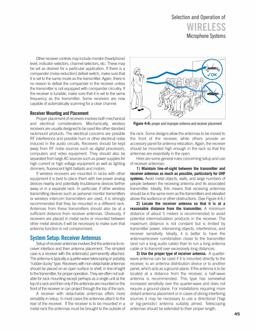
WIRELESSSelection and Operation of
Microphone Systems
45
Other receiver controls may include monitor (headphone)level, indicator selectors, channel selectors, etc. These maybe set as desired for a particular application. If there is acompander (noise reduction) defeat switch, make sure thatit is set to the same mode as the transmitter. Again, there isno reason to defeat the compander in the receiver unlessthe transmitter is not equipped with compander circuitry. Ifthe receiver is tunable, make sure that it is set to the samefrequency as the transmitter. Some receivers are now capable of automatically scanning for a clear channel.
Receiver Mounting and PlacementProper placement of receivers involves both mechanical
and electrical considerations. Mechanically, wireless receivers are usually designed to be used like other standardrackmount products. The electrical concerns are possibleRF interference and possible hum or other electrical noiseinduced in the audio circuits. Receivers should be kept away from RF noise sources such as digital processors, computers and video equipment. They should also be separated from large AC sources such as power supplies forhigh current or high voltage equipment as well as lightingdimmers, fluorescent light ballasts and motors.
If wireless receivers are mounted in racks with otherequipment it is best to place them with low-power analogdevices nearby and potentially troublesome devices fartheraway or in a separate rack. In particular, if other wirelesstransmitting devices such as personal monitor transmittersor wireless intercom transmitters are used, it is strongly recommended that they be mounted in a different rack.Antennas from these transmitters should also be at a sufficient distance from receiver antennas. Obviously, if receivers are placed in metal racks or mounted betweenother metal devices it will be necessary to make sure thatantenna function is not compromised.
System Setup: Receiver AntennasSetup of receiver antennas involves first the antenna-to-re-
ceiver interface and then antenna placement. The simplestcase is a receiver with the antenna(s) permanently attached.The antenna is typically a quarter-wave telescoping or possibly"rubber ducky" type. Receivers with non-detachable antennasshould be placed on an open surface or shelf, in line-of-sightto the transmitter, for proper operation. They are often not suit-able for rack mounting except perhaps as a single unit at thetop of a rack and then only if the antennas are mounted on thefront of the receiver or can project through the top of the rack.
A receiver with detachable antennas offers more versatility in setup. In most cases the antennas attach to therear of the receiver. If the receiver is to be mounted in ametal rack the antennas must be brought to the outside of
the rack. Some designs allow the antennas to be moved tothe front of the receiver, while others provide an accessory panel for antenna relocation. Again, the receivershould be mounted high enough in the rack so that theantennas are essentially in the open.
Here are some general rules concerning setup and useof receiver antennas:
1) Maintain line-of-sight between the transmitter and receiver antennas as much as possible, particularly for UHFsystems. Avoid metal objects, walls, and large numbers ofpeople between the receiving antenna and its associatedtransmitter. Ideally, this means that receiving antennasshould be in the same room as the transmitters and elevatedabove the audience or other obstructions. (See Figure 4-6.)
2) Locate the receiver antenna so that it is at a reasonable distance from the transmitter. A minimum distance of about 5 meters is recommended to avoid potential intermodulation products in the receiver. Themaximum distance is not constant but is limited by transmitter power, intervening objects, interference, andreceiver sensitivity. Ideally, it is better to have the antenna/receiver combination closer to the transmitter(and run a long audio cable) than to run a long antennacable or to transmit over excessively long distances.
3) Use the proper type of receiver antenna. A quarter-wave antenna can be used if it is mounted directly to thereceiver, to an antenna distribution device or to anotherpanel, which acts as a ground-plane. If the antenna is to belocated at a distance from the receiver, a half-wave antenna is recommended. This type has somewhat increased sensitivity over the quarter-wave and does notrequire a ground-plane. For installations requiring moredistant antenna placement or in cases of strong interferingsources it may be necessary to use a directional (Yagi or log-periodic) antenna suitably aimed. Telescoping antennas should be extended to their proper length.
✓OK
Figure 4-6: proper and improper antenna and receiver placement
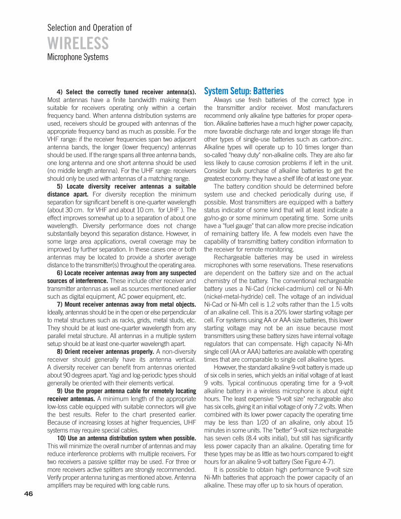
4) Select the correctly tuned receiver antenna(s).Most antennas have a finite bandwidth making them suitable for receivers operating only within a certain frequency band. When antenna distribution systems areused, receivers should be grouped with antennas of the appropriate frequency band as much as possible. For theVHF range: if the receiver frequencies span two adjacentantenna bands, the longer (lower frequency) antennasshould be used. If the range spans all three antenna bands,one long antenna and one short antenna should be used(no middle length antenna). For the UHF range: receiversshould only be used with antennas of a matching range.
5) Locate diversity receiver antennas a suitable distance apart. For diversity reception the minimum separation for significant benefit is one-quarter wavelength(about 30 cm. for VHF and about 10 cm. for UHF ). Theeffect improves somewhat up to a separation of about onewavelength. Diversity performance does not change substantially beyond this separation distance. However, insome large area applications, overall coverage may be improved by further separation. In these cases one or bothantennas may be located to provide a shorter average distance to the transmitter(s) throughout the operating area.
6) Locate receiver antennas away from any suspectedsources of interference. These include other receiver andtransmitter antennas as well as sources mentioned earliersuch as digital equipment, AC power equipment, etc.
7) Mount receiver antennas away from metal objects.Ideally, antennas should be in the open or else perpendicularto metal structures such as racks, grids, metal studs, etc.They should be at least one-quarter wavelength from anyparallel metal structure. All antennas in a multiple systemsetup should be at least one-quarter wavelength apart.
8) Orient receiver antennas properly. A non-diversity receiver should generally have its antenna vertical. A diversity receiver can benefit from antennas orientedabout 90 degrees apart. Yagi and log-periodic types shouldgenerally be oriented with their elements vertical.
9) Use the proper antenna cable for remotely locating receiver antennas. A minimum length of the appropriate low-loss cable equipped with suitable connectors will givethe best results. Refer to the chart presented earlier. Because of increasing losses at higher frequencies, UHFsystems may require special cables.
10) Use an antenna distribution system when possible.This will minimize the overall number of antennas and mayreduce interference problems with multiple receivers. Fortwo receivers a passive splitter may be used. For three ormore receivers active splitters are strongly recommended.Verify proper antenna tuning as mentioned above. Antennaamplifiers may be required with long cable runs.
System Setup: BatteriesAlways use fresh batteries of the correct type in
the transmitter and/or receiver. Most manufacturers recommend only alkaline type batteries for proper opera-tion. Alkaline batteries have a much higher power capacity,more favorable discharge rate and longer storage life thanother types of single-use batteries such as carbon-zinc. Alkaline types will operate up to 10 times longer than so-called "heavy duty" non-alkaline cells. They are also farless likely to cause corrosion problems if left in the unit. Consider bulk purchase of alkaline batteries to get the greatest economy: they have a shelf life of at least one year.
The battery condition should be determined before system use and checked periodically during use, if possible. Most transmitters are equipped with a battery status indicator of some kind that will at least indicate ago/no-go or some minimum operating time. Some unitshave a "fuel gauge" that can allow more precise indicationof remaining battery life. A few models even have the capability of transmitting battery condition information tothe receiver for remote monitoring.
Rechargeable batteries may be used in wireless microphones with some reservations. These reservationsare dependent on the battery size and on the actual chemistry of the battery. The conventional rechargeablebattery uses a Ni-Cad (nickel-cadmium) cell or Ni-Mh(nickel-metal-hydride) cell. The voltage of an individual Ni-Cad or Ni-Mh cell is 1.2 volts rather than the 1.5 voltsof an alkaline cell. This is a 20% lower starting voltage percell. For systems using AA or AAA size batteries, this lowerstarting voltage may not be an issue because most transmitters using these battery sizes have internal voltageregulators that can compensate. High capacity Ni-Mh single cell (AA or AAA) batteries are available with operatingtimes that are comparable to single cell alkaline types.
However, the standard alkaline 9-volt battery is made upof six cells in series, which yields an initial voltage of at least9 volts. Typical continuous operating time for a 9-volt alkaline battery in a wireless microphone is about eighthours. The least expensive "9-volt size" rechargeable alsohas six cells, giving it an initial voltage of only 7.2 volts. Whencombined with its lower power capacity the operating timemay be less than 1/20 of an alkaline, only about 15 minutes in some units. The "better" 9-volt size rechargeablehas seven cells (8.4 volts initial), but still has significantlyless power capacity than an alkaline. Operating time forthese types may be as little as two hours compared to eighthours for an alkaline 9-volt battery (See Figure 4-7).
It is possible to obtain high performance 9-volt size Ni-Mh batteries that approach the power capacity of an alkaline. These may offer up to six hours of operation.
Microphone Systems
Selection and Operation of
WIRELESS
46
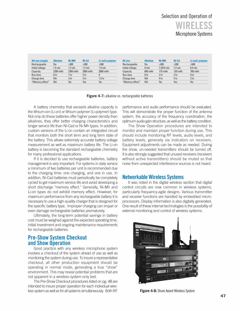
Microphone Systems
Selection and Operation of
WIRELESS
A battery chemistry that exceeds alkaline capacity isthe lithium-ion (Li-on) or lithium-polymer (Li-polymer) type.Not only do these batteries offer higher power density thanalkalines, they offer better charging characteristics andlonger service life than Ni-Cad or Ni-Mh types. In addition,custom versions of the Li-on contain an integrated circuitthat monitors both the short term and long term state ofthe battery. This allows extremely accurate battery voltagemeasurement as well as maximum battery life. The Li-onbattery is becoming the standard rechargeable chemistryfor many professional applications.
If it is decided to use rechargeable batteries, batterymanagement is very important. For systems in daily servicea minimum of two batteries per unit is recommended dueto the charging time: one charging, and one in use. In addition, Ni-Cad batteries must periodically be completelycycled to get maximum service life and avoid developing ashort discharge "memory effect." Generally, Ni-Mh and Li-on types do not exhibit memory effect. However, for maximum performance from any rechargeable battery it isnecessary to use a high-quality charger that is designed forthe specific battery type. Improper charging can impair oreven damage rechargeable batteries prematurely.
Ultimately, the long-term potential savings in batterycost must be weighed against the expected operating time,initial investment and ongoing maintenance requirementsfor rechargeable batteries.
Pre-Show System Checkout and Show Operation
Good practice with any wireless microphone system involves a checkout of the system ahead of use as well asmonitoring the system during use. To insure a representativecheckout, all other production equipment should be operating in normal mode, generating a true “show” environment. This may reveal potential problems that arenot apparent in a wireless-system-only test.
The Pre-Show Checkout procedures listed on pg. 48 areintended to insure proper operation for each individual wire-less system as well as for all systems simultaneously. Both RF
performance and audio performance should be evaluated.This will demonstrate the proper function of the antenna system, the accuracy of the frequency coordination, the optimum audio gain structure, as well as the battery condition.
The Show Operation procedures are intended to monitor and maintain proper function during use. Thisshould include monitoring RF levels, audio levels, and battery levels, generally via indicators on receivers. Equipment adjustments can be made as needed. Duringthe show, un-needed transmitters should be turned off. It is also strongly suggested that unused receivers (receiverswithout active transmitters) should be muted so that noise from unexpected interference sources is not heard.
Networkable Wireless SystemsIt was noted in the digital wireless section that digital
control circuits are now common in wireless systems, particularly frequency-agile designs. Various transmitterand receiver functions are handled by embedded micro-processors. Display information is also digitally generated.One result of these internal technologies is the possibility ofexternal monitoring and control of wireless systems.
Figure 4-7: alkaline vs. rechargeable batteries
47Figure 4-8: Shure Axient Wireless System
9V size Alkaline Ni-MH Ni-Cd Li-on/Li-polymerRechargeable No >300 >300 >500Initial voltage 9 vdc 7.2/8.4 vdc 7.2 vdc 8.4 vdcCapacity 600 mAh 175 mAh 120 mAh 700 mAhRun-time 8 hr 2 hr 2 hr 8 hrCharge time NA 4 hr 4 hr 2 hr“Memory effect” NA No Yes No
AA size (single) Alkaline Ni-MH Ni-Cd Li-on/Li-polymerRechargeable No >300 >300 >500Initial voltage 1.5 vdc 1.2 vdc 1.2 vdc 1.5 vdcCapacity 2200 mAh 2300 mAh 2000 mAh 2600 mAhRun-time 8 hr 7 hr 5 hr 8Charge time NA 3 hr 3 hr 1.5 hr“Memory effect” NA No Yes No
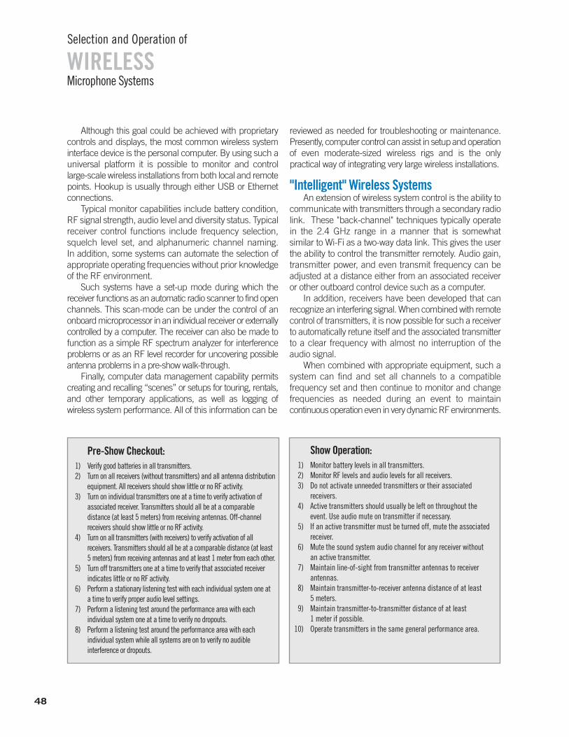
WIRELESSSelection and Operation of
Microphone Systems
Although this goal could be achieved with proprietary controls and displays, the most common wireless system interface device is the personal computer. By using such auniversal platform it is possible to monitor and control large-scale wireless installations from both local and remotepoints. Hookup is usually through either USB or Ethernet connections.
Typical monitor capabilities include battery condition,RF signal strength, audio level and diversity status. Typicalreceiver control functions include frequency selection,squelch level set, and alphanumeric channel naming. In addition, some systems can automate the selection of appropriate operating frequencies without prior knowledgeof the RF environment.
Such systems have a set-up mode during which the receiver functions as an automatic radio scanner to find openchannels. This scan-mode can be under the control of an onboard microprocessor in an individual receiver or externallycontrolled by a computer. The receiver can also be made tofunction as a simple RF spectrum analyzer for interferenceproblems or as an RF level recorder for uncovering possibleantenna problems in a pre-show walk-through.
Finally, computer data management capability permitscreating and recalling “scenes” or setups for touring, rentals,and other temporary applications, as well as logging of wireless system performance. All of this information can be
reviewed as needed for troubleshooting or maintenance.Presently, computer control can assist in setup and operationof even moderate-sized wireless rigs and is the only practical way of integrating very large wireless installations.
"Intelligent" Wireless SystemsAn extension of wireless system control is the ability to
communicate with transmitters through a secondary radiolink. These "back-channel" techniques typically operatein the 2.4 GHz range in a manner that is somewhat similar to Wi-Fi as a two-way data link. This gives the userthe ability to control the transmitter remotely. Audio gain,transmitter power, and even transmit frequency can be adjusted at a distance either from an associated receiveror other outboard control device such as a computer.
In addition, receivers have been developed that can recognize an interfering signal. When combined with remotecontrol of transmitters, it is now possible for such a receiverto automatically retune itself and the associated transmitterto a clear frequency with almost no interruption of theaudio signal.
When combined with appropriate equipment, such asystem can find and set all channels to a compatible frequency set and then continue to monitor and change frequencies as needed during an event to maintain continuous operation even in very dynamic RF environments.
48
Pre-Show Checkout:1) Verify good batteries in all transmitters.2) Turn on all receivers (without transmitters) and all antenna distribution
equipment. All receivers should show little or no RF activity.3) Turn on individual transmitters one at a time to verify activation of
associated receiver. Transmitters should all be at a comparable distance (at least 5 meters) from receiving antennas. Off-channel receivers should show little or no RF activity.
4) Turn on all transmitters (with receivers) to verify activation of all receivers. Transmitters should all be at a comparable distance (at least 5 meters) from receiving antennas and at least 1 meter from each other.
5) Turn off transmitters one at a time to verify that associated receiver indicates little or no RF activity.
6) Perform a stationary listening test with each individual system one ata time to verify proper audio level settings.
7) Perform a listening test around the performance area with eachindividual system one at a time to verify no dropouts.
8) Perform a listening test around the performance area with eachindividual system while all systems are on to verify no audibleinterference or dropouts.
Show Operation:1) Monitor battery levels in all transmitters.2) Monitor RF levels and audio levels for all receivers.3) Do not activate unneeded transmitters or their associated
receivers.4) Active transmitters should usually be left on throughout the
event. Use audio mute on transmitter if necessary.5) If an active transmitter must be turned off, mute the associated
receiver.6) Mute the sound system audio channel for any receiver without
an active transmitter.7) Maintain line-of-sight from transmitter antennas to receiver
antennas.8) Maintain transmitter-to-receiver antenna distance of at least
5 meters.9) Maintain transmitter-to-transmitter distance of at least
1 meter if possible.10) Operate transmitters in the same general performance area.
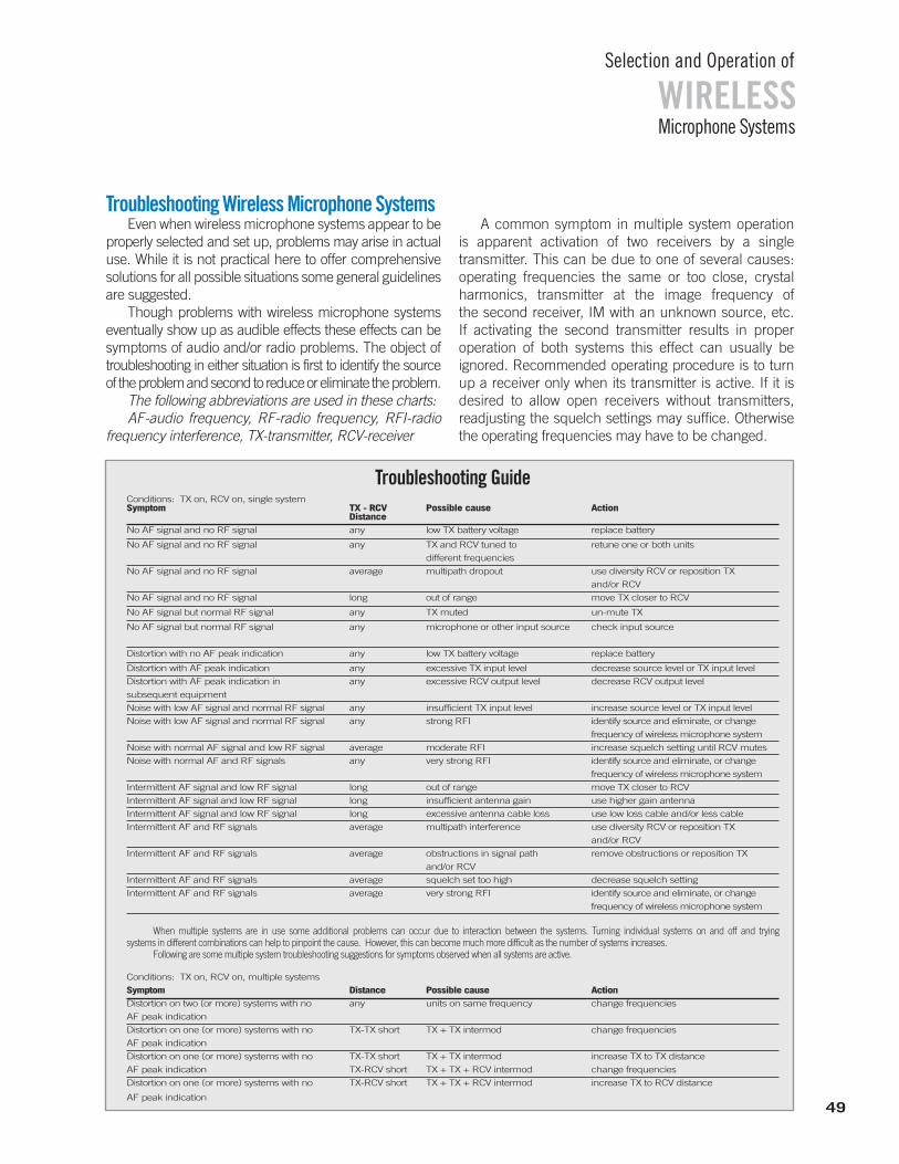
49
WIRELESSSelection and Operation of
Microphone Systems
Troubleshooting GuideConditions: TX on, RCV on, single systemSymptom TX - RCV Possible cause Action
Distance
No AF signal and no RF signal any low TX battery voltage replace battery
No AF signal and no RF signal any TX and RCV tuned to retune one or both units
different frequencies
No AF signal and no RF signal average multipath dropout use diversity RCV or reposition TX
and/or RCV
No AF signal and no RF signal long out of range move TX closer to RCV
No AF signal but normal RF signal any TX muted un-mute TX
No AF signal but normal RF signal any microphone or other input source check input source
Distortion with no AF peak indication any low TX battery voltage replace battery
Distortion with AF peak indication any excessive TX input level decrease source level or TX input level
Distortion with AF peak indication in any excessive RCV output level decrease RCV output level
subsequent equipment
Noise with low AF signal and normal RF signal any insufficient TX input level increase source level or TX input level
Noise with low AF signal and normal RF signal any strong RFI identify source and eliminate, or change
frequency of wireless microphone system
Noise with normal AF signal and low RF signal average moderate RFI increase squelch setting until RCV mutes
Noise with normal AF and RF signals any very strong RFI identify source and eliminate, or change
frequency of wireless microphone system
Intermittent AF signal and low RF signal long out of range move TX closer to RCV
Intermittent AF signal and low RF signal long insufficient antenna gain use higher gain antenna
Intermittent AF signal and low RF signal long excessive antenna cable loss use low loss cable and/or less cable
Intermittent AF and RF signals average multipath interference use diversity RCV or reposition TX
and/or RCV
Intermittent AF and RF signals average obstructions in signal path remove obstructions or reposition TX
and/or RCV
Intermittent AF and RF signals average squelch set too high decrease squelch setting
Intermittent AF and RF signals average very strong RFI identify source and eliminate, or change
frequency of wireless microphone system
When multiple systems are in use some additional problems can occur due to interaction between the systems. Turning individual systems on and off and trying systems in different combinations can help to pinpoint the cause. However, this can become much more difficult as the number of systems increases.
Following are some multiple system troubleshooting suggestions for symptoms observed when all systems are active.
Conditions: TX on, RCV on, multiple systems
Symptom Distance Possible cause Action
Distortion on two (or more) systems with no any units on same frequency change frequencies
AF peak indication
Distortion on one (or more) systems with no TX-TX short TX + TX intermod change frequencies
AF peak indication
Distortion on one (or more) systems with no TX-TX short TX + TX intermod increase TX to TX distance
AF peak indication TX-RCV short TX + TX + RCV intermod change frequencies
Distortion on one (or more) systems with no TX-RCV short TX + TX + RCV intermod increase TX to RCV distance
AF peak indication
Troubleshooting Wireless Microphone SystemsEven when wireless microphone systems appear to be
properly selected and set up, problems may arise in actualuse. While it is not practical here to offer comprehensivesolutions for all possible situations some general guidelinesare suggested.
Though problems with wireless microphone systems eventually show up as audible effects these effects can besymptoms of audio and/or radio problems. The object of troubleshooting in either situation is first to identify the sourceof the problem and second to reduce or eliminate the problem.
The following abbreviations are used in these charts: AF-audio frequency, RF-radio frequency, RFI-radio
frequency interference, TX-transmitter, RCV-receiver
A common symptom in multiple system operation is apparent activation of two receivers by a single transmitter. This can be due to one of several causes: operating frequencies the same or too close, crystal harmonics, transmitter at the image frequency of the second receiver, IM with an unknown source, etc. If activating the second transmitter results in proper operation of both systems this effect can usually be ignored. Recommended operating procedure is to turnup a receiver only when its transmitter is active. If it is desired to allow open receivers without transmitters, readjusting the squelch settings may suffice. Otherwisethe operating frequencies may have to be changed.
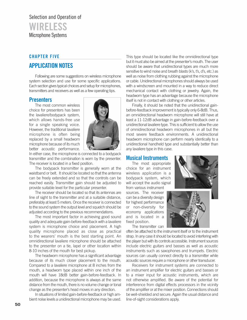
CHAPTER FIVE
APPLICATION NOTESFollowing are some suggestions on wireless microphone
system selection and use for some specific applications. Each section gives typical choices and setup for microphones,transmitters and receivers as well as a few operating tips.
PresentersThe most common wireless
choice for presenters has beenthe lavaliere/bodypack system,which allows hands-free use for a single speaking voice.However, the traditional lavalieremicrophone is often being replaced by a small headwornmicrophone because of its muchbetter acoustic performance. In either case, the microphone is connected to a bodypacktransmitter and the combination is worn by the presenter.The receiver is located in a fixed position.
The bodypack transmitter is generally worn at thewaistband or belt. It should be located so that the antennacan be freely extended and so that the controls can bereached easily. Transmitter gain should be adjusted to provide suitable level for the particular presenter.
The receiver should be located so that its antennas areline of sight to the transmitter and at a suitable distance,preferably at least 5 meters. Once the receiver is connectedto the sound system the output level and squelch should beadjusted according to the previous recommendations.
The most important factor in achieving good soundquality and adequate gain-before-feedback with a lavalieresystem is microphone choice and placement. A high quality microphone placed as close as practical to the wearers’ mouth is the best starting point. Anomnidirectional lavaliere microphone should be attached to the presenter on a tie, lapel or other location within 8-10 inches of the mouth for best pickup.
The headworn microphone has a significant advantagebecause of its much closer placement to the mouth. Compared to a lavaliere microphone at 8 inches from themouth, a headworn type placed within one inch of themouth will have 18dB better gain-before-feedback. In addition, because the microphone is always at the same distance from the mouth, there is no volume change or tonalchange as the presenter’s head moves in any direction.
In situations of limited gain-before-feedback or high am-bient noise levels a unidirectional microphone may be used.
This type should be located like the omnidirectional type but it must also be aimed at the presenter’s mouth. The usershould be aware that unidirectional types are much moresensitive to wind noise and breath blasts (k’s, t’s, d’s, etc.) aswell as noise from clothing rubbing against the microphoneor cable. Unidirectional microphones should always be usedwith a windscreen and mounted in a way to reduce directmechanical contact with clothing or jewelry. Again, theheadworn type has an advantage because the microphoneitself is not in contact with clothing or other articles.
Finally, it should be noted that the unidirectional gain-before-feedback improvement is typically only 6-8dB. Thus,an omnidirectional headworn microphone will still have atleast a 11-12dB advantage in gain-before-feedback over aunidirectional lavaliere type. This is sufficient to allow the useof omnidirectional headworn microphones in all but the most severe feedback environments. A unidirectional headworn microphone can perform nearly identically to aunidirectional handheld type and substantially better thanany lavaliere type in this case.
Musical InstrumentsThe most appropriate
choice for an instrument wireless application is abodypack system, which will accept the audio signal from various instrumentsources. The receivercan be a diversity designfor highest performanceor non-diversity foreconomy applicationsand is located in a fixed position.
The transmitter canoften be attached to the instrument itself or to the instrumentstrap. In any case it should be located to avoid interfering withthe player but with its controls accessible. Instrument sourcesinclude electric guitars and basses as well as acoustic instruments such as saxophones and trumpets. Electricsources can usually connect directly to a transmitter whileacoustic sources require a microphone or other transducer.
Receivers for instrument systems are connected to an instrument amplifier for electric guitars and basses or to a mixer input for acoustic instruments, which are not otherwise amplified. Be aware of the potential for interference from digital effects processors in the vicinityof the amplifier or at the mixer position. Connections shouldbe well-shielded and secure. Again the usual distance andline-of-sight considerations apply.
Microphone Systems
Selection and Operation of
WIRELESS
50
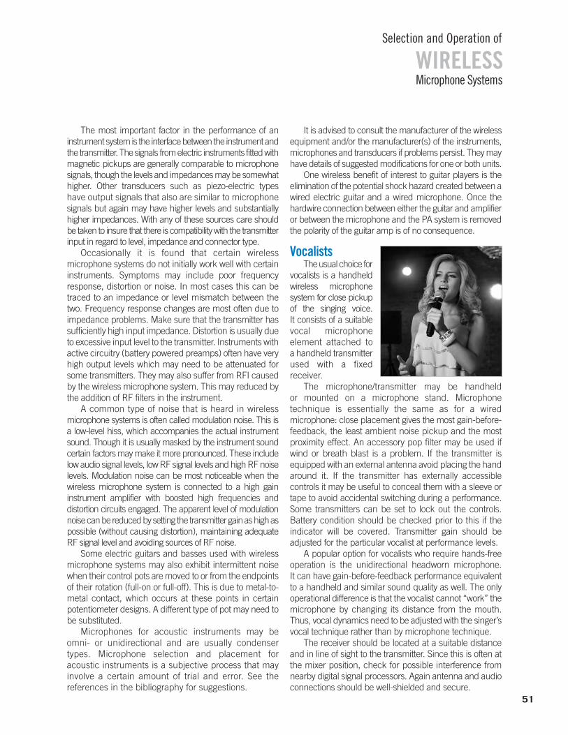
The most important factor in the performance of aninstrument system is the interface between the instrument andthe transmitter. The signals from electric instruments fitted withmagnetic pickups are generally comparable to microphonesignals, though the levels and impedances may be somewhathigher. Other transducers such as piezo-electric types have output signals that also are similar to microphonesignals but again may have higher levels and substantiallyhigher impedances. With any of these sources care shouldbe taken to insure that there is compatibility with the transmitterinput in regard to level, impedance and connector type.
Occasionally it is found that certain wireless microphone systems do not initially work well with certaininstruments. Symptoms may include poor frequency response, distortion or noise. In most cases this can betraced to an impedance or level mismatch between thetwo. Frequency response changes are most often due toimpedance problems. Make sure that the transmitter hassufficiently high input impedance. Distortion is usually dueto excessive input level to the transmitter. Instruments withactive circuitry (battery powered preamps) often have veryhigh output levels which may need to be attenuated forsome transmitters. They may also suffer from RFI causedby the wireless microphone system. This may reduced bythe addition of RF filters in the instrument.
A common type of noise that is heard in wirelessmicrophone systems is often called modulation noise. This isa low-level hiss, which accompanies the actual instrumentsound. Though it is usually masked by the instrument soundcertain factors may make it more pronounced. These includelow audio signal levels, low RF signal levels and high RF noiselevels. Modulation noise can be most noticeable when thewireless microphone system is connected to a high gain instrument amplifier with boosted high frequencies and distortion circuits engaged. The apparent level of modulationnoise can be reduced by setting the transmitter gain as high aspossible (without causing distortion), maintaining adequate RF signal level and avoiding sources of RF noise.
Some electric guitars and basses used with wirelessmicrophone systems may also exhibit intermittent noisewhen their control pots are moved to or from the endpointsof their rotation (full-on or full-off). This is due to metal-to-metal contact, which occurs at these points in certain potentiometer designs. A different type of pot may need tobe substituted.
Microphones for acoustic instruments may be omni- or unidirectional and are usually condensertypes. Microphone selection and placement foracoustic instruments is a subjective process that mayinvolve a certain amount of trial and error. See the references in the bibliography for suggestions.
It is advised to consult the manufacturer of the wirelessequipment and/or the manufacturer(s) of the instruments,microphones and transducers if problems persist. They mayhave details of suggested modifications for one or both units.
One wireless benefit of interest to guitar players is theelimination of the potential shock hazard created between awired electric guitar and a wired microphone. Once thehardwire connection between either the guitar and amplifieror between the microphone and the PA system is removedthe polarity of the guitar amp is of no consequence.
VocalistsThe usual choice for
vocalists is a handheldwireless microphone system for close pickup of the singing voice. It consists of a suitable vocal microphone element attached to a handheld transmitter used with a fixed receiver.
The microphone/transmitter may be handheld or mounted on a microphone stand. Microphone technique is essentially the same as for a wired microphone: close placement gives the most gain-before-feedback, the least ambient noise pickup and the mostproximity effect. An accessory pop filter may be used ifwind or breath blast is a problem. If the transmitter isequipped with an external antenna avoid placing the handaround it. If the transmitter has externally accessible controls it may be useful to conceal them with a sleeve ortape to avoid accidental switching during a performance.Some transmitters can be set to lock out the controls. Battery condition should be checked prior to this if the indicator will be covered. Transmitter gain should be adjusted for the particular vocalist at performance levels.
A popular option for vocalists who require hands-freeoperation is the unidirectional headworn microphone. It can have gain-before-feedback performance equivalentto a handheld and similar sound quality as well. The onlyoperational difference is that the vocalist cannot “work” themicrophone by changing its distance from the mouth.Thus, vocal dynamics need to be adjusted with the singer’svocal technique rather than by microphone technique.
The receiver should be located at a suitable distanceand in line of sight to the transmitter. Since this is often atthe mixer position, check for possible interference fromnearby digital signal processors. Again antenna and audioconnections should be well-shielded and secure.
Microphone Systems
Selection and Operation of
WIRELESS
51
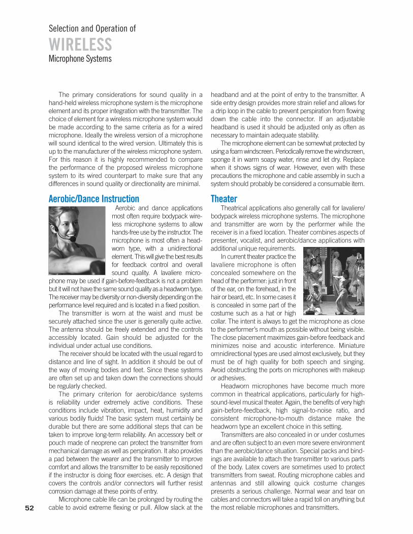
The primary considerations for sound quality in a hand-held wireless microphone system is the microphoneelement and its proper integration with the transmitter. Thechoice of element for a wireless microphone system wouldbe made according to the same criteria as for a wired microphone. Ideally the wireless version of a microphonewill sound identical to the wired version. Ultimately this isup to the manufacturer of the wireless microphone system.For this reason it is highly recommended to compare the performance of the proposed wireless microphone system to its wired counterpart to make sure that any differences in sound quality or directionality are minimal.
Aerobic/Dance InstructionAerobic and dance applications
most often require bodypack wire-less microphone systems to allowhands-free use by the instructor. Themicrophone is most often a head-worn type, with a unidirectional element. This will give the best resultsfor feedback control and overallsound quality. A lavaliere micro-
phone may be used if gain-before-feedback is not a problembut it will not have the same sound quality as a headworn type.The receiver may be diversity or non-diversity depending on theperformance level required and is located in a fixed position.
The transmitter is worn at the waist and must be securely attached since the user is generally quite active.The antenna should be freely extended and the controlsaccessibly located. Gain should be adjusted for the individual under actual use conditions.
The receiver should be located with the usual regard todistance and line of sight. In addition it should be out ofthe way of moving bodies and feet. Since these systemsare often set up and taken down the connections shouldbe regularly checked.
The primary criterion for aerobic/dance systemsis reliability under extremely active conditions. These conditions include vibration, impact, heat, humidity and various bodily fluids! The basic system must certainly bedurable but there are some additional steps that can betaken to improve long-term reliability. An accessory belt orpouch made of neoprene can protect the transmitter frommechanical damage as well as perspiration. It also providesa pad between the wearer and the transmitter to improvecomfort and allows the transmitter to be easily repositionedif the instructor is doing floor exercises. etc. A design thatcovers the controls and/or connectors will further resist corrosion damage at these points of entry.
Microphone cable life can be prolonged by routing thecable to avoid extreme flexing or pull. Allow slack at the
headband and at the point of entry to the transmitter. Aside entry design provides more strain relief and allows fora drip loop in the cable to prevent perspiration from flowingdown the cable into the connector. If an adjustable headband is used it should be adjusted only as often asnecessary to maintain adequate stability.
The microphone element can be somewhat protected byusing a foam windscreen. Periodically remove the windscreen,sponge it in warm soapy water, rinse and let dry. Replace when it shows signs of wear. However, even with these precautions the microphone and cable assembly in such asystem should probably be considered a consumable item.
TheaterTheatrical applications also generally call for lavaliere/
bodypack wireless microphone systems. The microphoneand transmitter are worn by the performer while the receiver is in a fixed location. Theater combines aspects ofpresenter, vocalist, and aerobic/dance applications withadditional unique requirements.
In current theater practice thelavaliere microphone is often concealed somewhere on thehead of the performer: just in frontof the ear, on the forehead, in thehair or beard, etc. In some cases itis concealed in some part of thecostume such as a hat or high collar. The intent is always to get the microphone as closeto the performer’s mouth as possible without being visible.The close placement maximizes gain-before feedback andminimizes noise and acoustic interference. Miniature omnidirectional types are used almost exclusively, but theymust be of high quality for both speech and singing. Avoid obstructing the ports on microphones with makeupor adhesives.
Headworn microphones have become much morecommon in theatrical applications, particularly for high-sound-level musical theater. Again, the benefits of very highgain-before-feedback, high signal-to-noise ratio, and consistent microphone-to-mouth distance make the headworn type an excellent choice in this setting.
Transmitters are also concealed in or under costumesand are often subject to an even more severe environmentthan the aerobic/dance situation. Special packs and bind-ings are available to attach the transmitter to various partsof the body. Latex covers are sometimes used to protecttransmitters from sweat. Routing microphone cables andantennas and still allowing quick costume changes presents a serious challenge. Normal wear and tear on cables and connectors will take a rapid toll on anything butthe most reliable microphones and transmitters.
Microphone Systems
Selection and Operation of
WIRELESS
52

Receivers for theatrical applications are not unique butthey must be of high quality to allow multiple system use with-out interference. It is not unusual to use as many as 30 simultaneous wireless microphone systems in a professionalmusical theater production. This number can only be handledwith systems operating in the UHF range. 10 to 12 systemsis the practical limit at VHF frequencies. In addition, separateantennas and antenna distribution systems are necessary forany installation involving a large number of systems.
Though small-scale theater applications can be done witha moderate investment in planning and equipment, large-scale productions usually require professional coordination ofwireless microphone systems to achieve successful results.This becomes an absolute necessity for a touring production.
WorshipWorship services may include
presenter, vocalist and instrumentapplications. While wireless vocaland instrument use is essentiallythe same as outlined in the preceding sections, the presenterfunction may be somewhat different. Microphone, transmitterand receiver selection are as before but placement of thecomponents may require extra consideration.
In particular, proper location of the lavaliere microphoneand/or transmitter may pose problems because of robes orvestments. It is still necessary to position the microphone asclose as practical the user’s mouth for best results. Differentmethods of attachment may be necessary. Access to trans-mitter controls can also be problematic. Use of accessorymicrophone mute switches similar to those worn by sportsreferees can be the answer. Though an omnidirectional typemicrophone is easier to use, a unidirectional model may bechosen to allow more gain-before-feedback. In this case popsensitivity and mechanical noise should be taken into account. Again it is very important to adjust the transmitterlevel for the individuals’ voice under actual conditions.
Note that headworn microphones are becoming moreacceptable for worship applications. They provide the highest gain-before-feedback in a hands-free type.
Because most worship services involve both wiredlectern microphones and wireless lavaliere microphones itoften happens that the person wearing the wireless is alsospeaking at the lectern. If the voice is picked up by both microphones an acoustic phenomenon known as "comb filtering" occurs which creates a hollow, unnatural sound.The solution is to turn down one of the two microphoneswhenever they are within one or two feet of each other. In most cases it will be less noticeable to turn down thelectern microphone when the wireless wearer approaches it.
Proper frequency selection is necessary for any worshipapplication. Since a fixed location is the norm, unused TVchannel frequencies are the best recommendation, not"traveling" frequencies. The simultaneous use of other wireless microphone systems by vocalists and musiciansduring the service must be considered as well. In addition,wireless microphone systems at other churches or facilitieswithin 1000 feet of the site should be included in any program for frequency coordination.
Finally, receivers should be located and adjusted according to the suggestions made earlier. Even with propersquelch settings, though, it is very strongly recommended toturn off or turn down the outputs of any receivers that donot have an active transmitter. This will avoid noise from random RF interference being heard in the sound system.
Conference/CorporateThe growth of videoconferencing in meeting rooms
and the increasing popularity of rooms with flexible seating layouts have made wireless microphones a popular optionin corporate settings.
Wireless boundary or goose-neck microphones can provideexcellent coverage of participantsseated around a conferencetable or at smaller tables arrangedclassroom-style. The wirelessform factor eliminates the needto drill holes in the table and allows the microphones to beput away when they are not needed.
Transmitters should be equipped with a convenient muteswitch and an illuminated indicator that confirms the microphone status. Battery life should allow a full day ofuse, and rechargeable transmitters than can be stored in a charging station are convenient and intuitive for non-technicalusers. Robust standards-based encryption (such as AES-128or AES-256) is often desired by corporate wireless users whodesire privacy when confidential business is discussed.
Receivers mounted in an equipment rack should beconnected to remote antennas that are in the meeting roomitself. New antenna designs that resemble a wireless accesspoint blend into the room décor more easily. A digital audionetwork connection (such as Dante) may make connectingto a digital audio processor simpler.
Spectral efficiency is important if many conferencerooms in a facility will be equipped with wireless micro-phones. Some systems are capable of operating in a “highdensity” mode that enables many systems to fit in just oneor two vacant TV channels. The 1.9 GHz DECT band is alsoa good option in the U.S. and many other countries, and isoutside the TV band which may be an advantage in urbanareas where TV signals are strong.
Microphone Systems
Selection and Operation of
WIRELESS
53
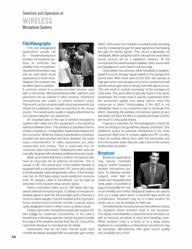
Film/VideographyFilm and videography
applications usually call for lavaliere/bodypackwireless microphone sys-tems to minimize thevisibility of the microphone. Handheld transmitters mayalso be used when visual appearance is not an issue. However, the receivers maybe either fixed or portable.A common choice is a camera-mounted receiver used with a camcorder. Microphone/transmitter selection and placement are as outlined in other sections. Directional microphones are useful to control ambient noise.Placement can be consistent with visual requirements but should be positioned as close as practical to the sound source. The overall audio quality is largely determined by microphone selection and placement.
An important area in the use of wireless microphonesystems with video and film equipment is the electrical interface between them. The interface is specified in termsof level, impedance, configuration (balanced/unbalanced)and connector. While the output characteristics of wirelessreceivers are well specified and fairly standard, the audioinput characteristics of video equipment are often unspecified and unique. This is especially true forconsumer video camcorders. Professional video units arenormally designed with standard professional audio inputs.
Most camcorders that have a built-in microphone alsohave an input jack for an external microphone. This is usually a 1/8" mini phone jack. If the wireless receiver isequipped with a microphone-level 1/4" phone jack outputa simple adapter cable will generally suffice. If the receiveronly has an XLR-type output some additional concernsarise. An adapter cable or transformer can be used as described in the receiver setup section above.
Stereo camcorders often use an 1/8" stereo (tip-ring-sleeve) external microphone jack. To deliver a monophonicwireless signal to both the left and right audio channels amono-to-stereo adapter must be inserted at the input jack.Some camera-mount receivers include a special outputcable designed to work in either mono or stereo inputs.
Certain camcorder microphone inputs also supply a DCbias voltage for condenser microphones. In this case a transformer or blocking capacitor may be required to isolatethe output of the wireless receiver from the DC. Consult the camcorder literature or manufacturer for details.
Camcorders that do not have manual audio level controls are always equipped with an automatic gain control
(AGC). Its function is to maintain a constant audio recordinglevel by increasing the gain for weak signals and decreasingthe gain for strong signals. This circuit is generally not defeatable. When using the built-in microphone most directsound sources are at a significant distance. At the microphone the overall variation between direct sound leveland background sound level is not very large.
Close-talked microphones, either handheld or lavaliere,present a much stronger signal relative to the backgroundsound level. With these devices the AGC will operate athigh gain when only background sound is present and willquickly reduce gain when a strong close-talk signal occurs.This will result in audible "pumping" of the backgroundnoise level. The same effect is typically heard in live sportsbroadcasts: the crowd noise is quickly suppressed whenthe announcer speaks and slowly returns when the announcer is silent. Unfortunately, if the AGC is not defeatable there is no convenient way to eliminate this effect. Operating the wireless microphone system at verylow levels can force the AGC to operate at full gain but thiswill result in noisy audio tracks.
Frequency selection for film/videography should bedone according to the guidelines already presented. Oneadditional source of potential interference is the videoequipment itself since it contains digital and RF circuitry.Listen for audible effects from both the transmitter andfrom the receiver when they are used close to the cameraand/or video recorders.
BroadcastBroadcast applications
may require handheld, plug-on and/or bodypackwireless microphone sys-tems. To interview randomsubjects most field re-porters and roving talk showhosts prefer a handheld orplug-on transmitter for max-imum mobility and control. Bodypack systems are used topick up a single talent when a handheld type would be cumbersome. Receivers may be in a fixed location for studio use or may be portable for field use.
Omnidirectional microphones are the preferred choicefor situations where ambient noise is not excessive. This allows more flexibility in placement and orientation aswell as reduced sensitivity to wind and handling noise.When ambient noise is a factor or in a setup where feedback is a possibility a unidirectional microphone maybe necessary. Microphones with good sound quality and durability are a must.
Microphone Systems
Selection and Operation of
WIRELESS
54
Lavaliere microphones will require a bodypack transmitter. If a desired handheld microphone model isavailable in a wireless version it can be used directly. Sincemost handheld transmitters use unidirectional microphoneelements a plug-on transmitter may be necessary for usewith handheld omnidirectional microphones or other wiredhand-held models.
Even for portable or camera-mount use a diversity receiver is standard choice for professional broadcast applications. Antenna location should be well planned, especially when used in a studio environment with lighting grids and other large metal structures. Receiversshould be located away from lighting controllers, digitalaudio equipment and video equipment that may produce interference. Balanced audio lines are also standard procedure.
Receivers used in remote trucks face interference notonly from nearby audio and video equipment but they mayalso be subject to interference from two-way radio systemsand remote-to-studio transmitters operating on VHF orUHF frequencies. Two-way transceivers should not be operated close to wireless transmitters or receivers. The wireless microphone system receivers should also be located well away from remote link transmitters. In addition, both the wireless microphone system antennasand the remote link antennas should be properly installedfor minimum interference with each other.
Frequency selection for broadcast involves the same considerations as in other applications for studio use. InENG (Electronic News Gathering) or EFP (Electronic Field Production) situations the additional factors of nearby remote transmitters and the possibility of wireless microphone systems in use by other broadcast crews mustbe taken into account. In a local area it is sometimes possi-ble to coordinate frequencies between different stationsahead of time to reduce the likelihood of frequency conflictat a news site. Specifying high quality frequency-agile wire-less equipment will further minimize interference problems.
Point-to-Point WirelessIntroduction
Often it is desirable (or even mandatory) to send anaudio signal from one fixed location to another fixed location without wires. This is termed "point-to-point" wireless. In some cases this may involve a single transmit location and multiple receive locations, referred to as "point-to-multi-point" wireless. Possible applications includeremote speaker/amplifier locations, remote recording/broadcast operations, and one-way communication links. Potentially this could be accomplished either by opticaltransmission or by radio frequency transmission.
Optical methods are inherently limited to line-of-sightconditions. The use of conventional (non-directional) infrared transmission is limited by ambient light levels vs. practical infrared power levels. Modulated laser transmission (highly directional) is another optical possibility but available systems are primarily geared to high-speed data/video transmission and are not widely (or affordably) distributed.
Low-power radio transmission systems, on the otherhand, are both widely available and relatively affordable.For radio signals, line-of-sight conditions are desirable butthey are not strictly required. In addition, point-to-multi-point is more easily accomplished with a single radiotransmitter.
Most radio communication products such as wirelessintercoms, two-way radios, and mobile phones are unsuitable due to lack of audio fidelity. However, two common high-fidelity radio products that can be used in apoint-to-point application are the wireless microphone system and the wireless in-ear monitor system. Each ofthese has slightly different concerns/advantages in performance and in setup.
Using wireless microphones for point-to-pointA bodypack wireless system can fulfill the
requirements above with two modifications. (See Figure5-1.) First, though many receivers have line level outputs,few transmitters are capable of accepting a line levelinput signal. This can be accomplished by using an external pad or attenuator at the transmitter input. Second, though most receivers run on AC power, transmitters are battery-only devices. Using a suitable external DC power supply can provide the necessary AC capability for the transmitter.
Once the input signal is sufficiently attenuated andpower is provided, the bodypack transmitter should be located to provide the best line-of-sight to the receiver. Thisusually involves securing the pack to a pole or some otherelevated structure. If wet weather is a factor, the transmittercan be protected by a "ziplock" bag or other covering.
At the receiver, no modification is usually requiredsince it is AC powered and has a line level output.
General requirements for point-to-point wireless include:
• High fidelity audio• Line level in and line level out• AC-power capability for both transmitter and receiver• "Sufficient" transmission distance
Microphone Systems
Selection and Operation of
WIRELESS
55
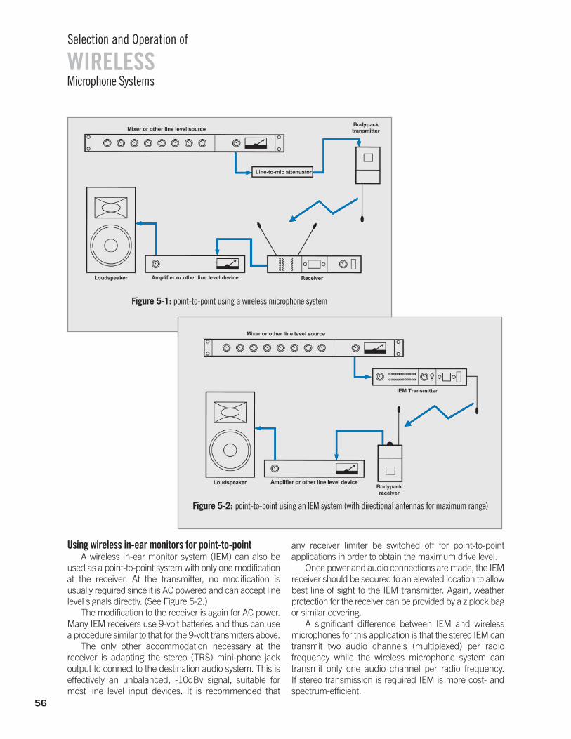
Using wireless in-ear monitors for point-to-pointA wireless in-ear monitor system (IEM) can also be
used as a point-to-point system with only one modificationat the receiver. At the transmitter, no modification is usually required since it is AC powered and can accept linelevel signals directly. (See Figure 5-2.)
The modification to the receiver is again for AC power.Many IEM receivers use 9-volt batteries and thus can usea procedure similar to that for the 9-volt transmitters above.
The only other accommodation necessary at the receiver is adapting the stereo (TRS) mini-phone jack output to connect to the destination audio system. This iseffectively an unbalanced, -10dBv signal, suitable for most line level input devices. It is recommended that
any receiver limiter be switched off for point-to-point applications in order to obtain the maximum drive level.
Once power and audio connections are made, the IEMreceiver should be secured to an elevated location to allowbest line of sight to the IEM transmitter. Again, weather protection for the receiver can be provided by a ziplock bagor similar covering.
A significant difference between IEM and wireless microphones for this application is that the stereo IEM cantransmit two audio channels (multiplexed) per radio frequency while the wireless microphone system cantransmit only one audio channel per radio frequency. If stereo transmission is required IEM is more cost- andspectrum-efficient.
Figure 5-1: point-to-point using a wireless microphone system
Figure 5-2: point-to-point using an IEM system (with directional antennas for maximum range)
Microphone Systems
Selection and Operation of
WIRELESS
56
Combining in-ear monitors with wireless microphones for point-to-point
It is sometimes possible to use an IEM transmitter inconjunction with a wireless microphone receiver to createa point-to-point system that is already set up at each endfor line-level audio signals and AC power. The principle requirements are that the operating frequencies match andthat the audio companding schemes are compatible. Ofcourse only mono audio signals may be transmitted due tothe mono nature of the wireless microphone receiver.
The one modification that may be needed is to defeatthe squelch circuit of the wireless microphone receiver.Certain IEM transmitters can now be used with compatiblewireless microphone receivers without defeating tone-keysquelch in the receiver. This is accomplished by a menusetting in the IEM transmitter which matches its tone-keyfrequency to that of the receiver.
Finally, it may be possible to use a wireless microphonetransmitter with an IEM receiver to create an entirely battery-powered point-to-point system. Again, the radio frequencies and companding schemes must match.However, it is probably more efficient to use a wireless microphone with a matching camera-mount type receiverif a completely battery-powered system is the goal.
AntennasThe antennas supplied with most wireless products
are omnidirectional. These are suitable for both point-to-point and point-to-multi-point applications. If additional transmission range is required it may be possible to use directional receiving and/or transmitting antenna(s). Note that although diversity receivers are always preferredit may not be necessary (or practical) to use directional antennas on both antenna inputs for point-to-point. Sincethe transmitter and receiver locations are assumed to be fixed in this application, multipath variations should beminimal once the equipment is set up.
Maximum range of point-to-point wireless The practical range for most of these systems in point-
to-point applications is comparable to their published rangein normal usage. For standard wireless systems this rangesfrom about 150 ft. to 800 ft. depending on various conditions. Directional antennas may boost these rangesby 50%. Good line of sight and the normal precautions forfrequency selection are assumed.
The maximum range system employs an IEM transmitter with either an IEM receiver or a suitable wire-less microphone receiver. The range advantage of these systems is due to two factors: first, the transmitter power ishigher, up to 100mW. This is at least twice the power ofmost wireless microphone systems. Second, since boththe transmitter and the receiver may have detachable antennas, it is possible to use a directional antenna on boththe transmitter and the receiver.
In operation, the receiving and transmitting antennasshould be pointed toward each other and oriented vertically. Elevation for best line of sight will further improverange. Such a system may be capable of stereo transmissionup to 2500 ft and mono operation up to 3500 ft.
If greater distances are required, it can be accomplishedby using an additional system as "repeater." That is, at the location of the first receiver a second transmitter is set up torebroadcast the signal to a more distant second receiver. Of course, each of these additional systems has to be on adifferent compatible frequency. The practical limit for a repeater system using standard wireless equipment is about3 "hops" due to increased noise and distortion.
SummaryIt is possible to employ wireless systems for point-
to-point applications in several ways. Both wireless microphone systems and IEM systems can be used, eachwith different adaptations. The modifications are primarilyfor AC powering of battery powered devices and for matching audio signal levels. Special connectors and/oradapters may also be necessary in some cases.
For moderate distance, single channel applicationsmay use wireless microphone systems for good results. Multi-channel, especially stereo, transmission may benefitfrom the IEM approach. Longer distance uses will requiredirectional antennas for wireless microphone receivers orfor IEM transmitters. Maximum range applications can behandled by the dual directional antenna IEM setup or byusing multiple systems in a repeater configuration.
Microphone Systems
Selection and Operation of
WIRELESS
57
Conclusion
Microphone Systems
Selection and Operation of
WIRELESS
58
To the extent that wireless audio technology is a work in progress, this presentation
is also a work in progress. As new radio technologies develop, new applications
will arise to take advantage of them. At the same time, new spectrum rules and
allocations will likely challenge the capability of wireless equipment suppliers and
users to provide successful solutions for those applications.
Implementing successful solutions will rely not just on the programmed
"intelligence" built into the equipment but also on the dynamic intelligence of the
people specifying and using the equipment. That intelligence comes both from
study of the principles underlying the technology and from experience gained by
using the technology in real-world situations.
It is hoped that the material presented in this publication will serve as a useful
reference on the technical principles of wireless audio transmission, as well as a
practical guide to using those principles in a wide variety of applications.
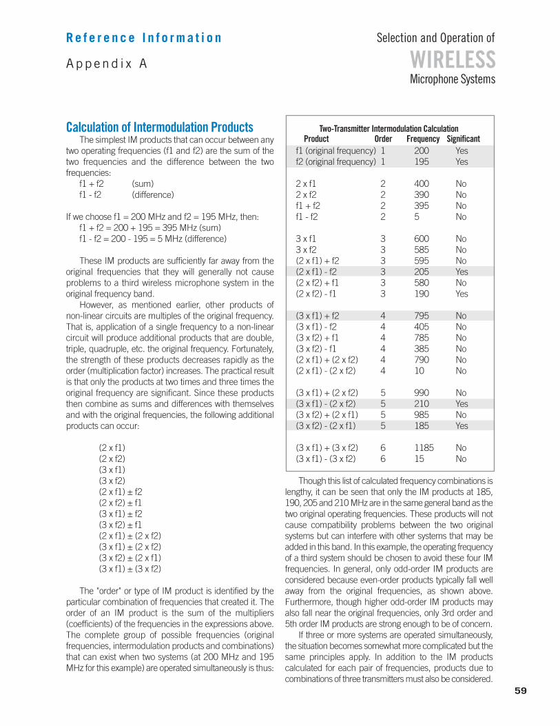
Append i x A
R e f e r e n c e I n f o r m a t i o n
Calculation of Intermodulation Products The simplest IM products that can occur between any
two operating frequencies (f1 and f2) are the sum of thetwo frequencies and the difference between the two frequencies:
f1 + f2 (sum)f1 - f2 (difference)
If we choose f1 = 200 MHz and f2 = 195 MHz, then: f1 + f2 = 200 + 195 = 395 MHz (sum)f1 - f2 = 200 - 195 = 5 MHz (difference)
These IM products are sufficiently far away from theoriginal frequencies that they will generally not cause problems to a third wireless microphone system in the original frequency band.
However, as mentioned earlier, other products of non-linear circuits are multiples of the original frequency.That is, application of a single frequency to a non-linearcircuit will produce additional products that are double,triple, quadruple, etc. the original frequency. Fortunately,the strength of these products decreases rapidly as theorder (multiplication factor) increases. The practical resultis that only the products at two times and three times theoriginal frequency are significant. Since these productsthen combine as sums and differences with themselvesand with the original frequencies, the following additional products can occur:
(2 x f1)(2 x f2)(3 x f1)(3 x f2)(2 x f1) ± f2(2 x f2) ± f1(3 x f1) ± f2(3 x f2) ± f1(2 x f1) ± (2 x f2)(3 x f1) ± (2 x f2)(3 x f2) ± (2 x f1)(3 x f1) ± (3 x f2)
The "order" or type of IM product is identified by theparticular combination of frequencies that created it. Theorder of an IM product is the sum of the multipliers (coefficients) of the frequencies in the expressions above.The complete group of possible frequencies (original frequencies, intermodulation products and combinations)that can exist when two systems (at 200 MHz and 195MHz for this example) are operated simultaneously is thus:
Two-Transmitter Intermodulation CalculationProduct Order Frequency Significant
f1 (original frequency) 1 200 Yesf2 (original frequency) 1 195 Yes
2 x f1 2 400 No2 x f2 2 390 Nof1 + f2 2 395 Nof1 - f2 2 5 No
3 x f1 3 600 No3 x f2 3 585 No(2 x f1) + f2 3 595 No(2 x f1) - f2 3 205 Yes(2 x f2) + f1 3 580 No(2 x f2) - f1 3 190 Yes
(3 x f1) + f2 4 795 No(3 x f1) - f2 4 405 No(3 x f2) + f1 4 785 No(3 x f2) - f1 4 385 No(2 x f1) + (2 x f2) 4 790 No(2 x f1) - (2 x f2) 4 10 No
(3 x f1) + (2 x f2) 5 990 No(3 x f1) - (2 x f2) 5 210 Yes(3 x f2) + (2 x f1) 5 985 No(3 x f2) - (2 x f1) 5 185 Yes
(3 x f1) + (3 x f2) 6 1185 No(3 x f1) - (3 x f2) 6 15 No
Though this list of calculated frequency combinations islengthy, it can be seen that only the IM products at 185,190, 205 and 210 MHz are in the same general band as thetwo original operating frequencies. These products will notcause compatibility problems between the two original systems but can interfere with other systems that may beadded in this band. In this example, the operating frequencyof a third system should be chosen to avoid these four IMfrequencies. In general, only odd-order IM products are considered because even-order products typically fall wellaway from the original frequencies, as shown above. Furthermore, though higher odd-order IM products mayalso fall near the original frequencies, only 3rd order and 5th order IM products are strong enough to be of concern.
If three or more systems are operated simultaneously,the situation becomes somewhat more complicated but thesame principles apply. In addition to the IM products calculated for each pair of frequencies, products due tocombinations of three transmitters must also be considered.
Microphone Systems
Selection and Operation of
WIRELESS
59
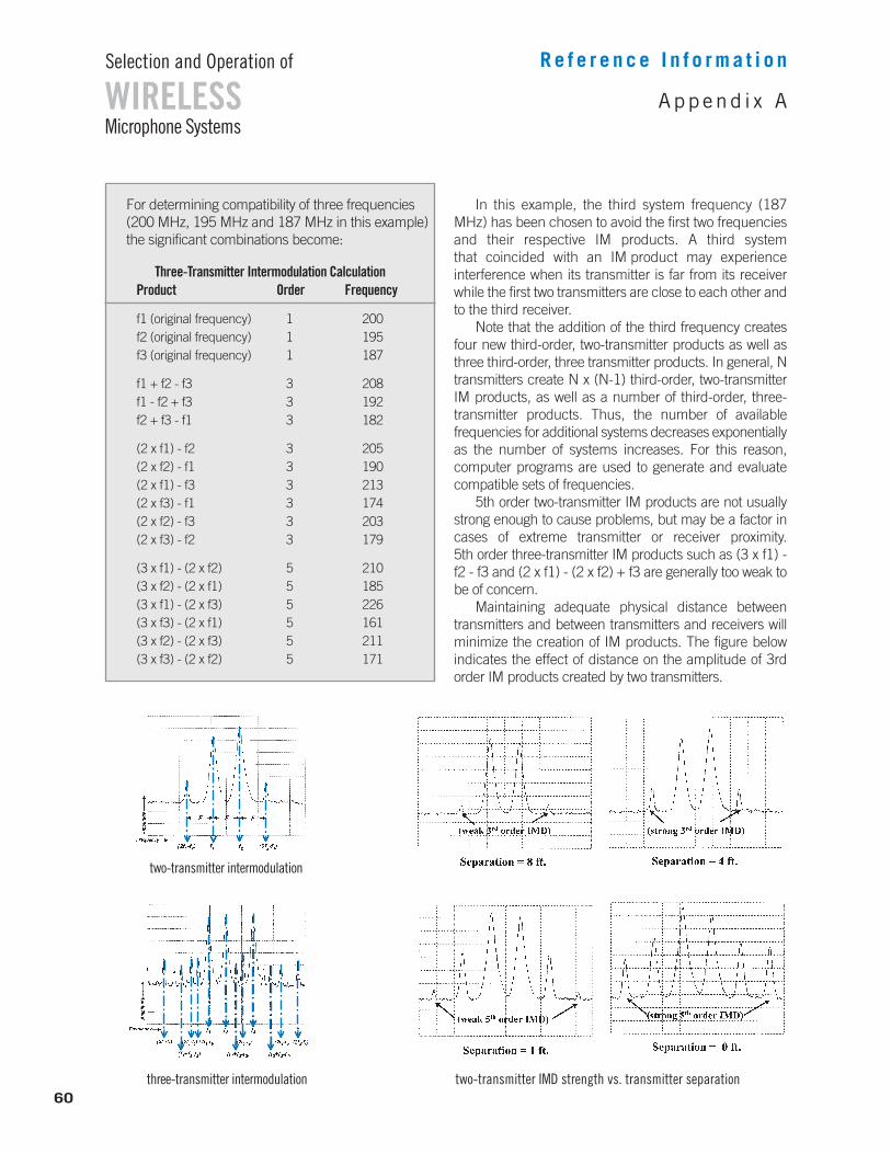
In this example, the third system frequency (187MHz) has been chosen to avoid the first two frequenciesand their respective IM products. A third system that coincided with an IM product may experience interference when its transmitter is far from its receiverwhile the first two transmitters are close to each other andto the third receiver.
Note that the addition of the third frequency createsfour new third-order, two-transmitter products as well asthree third-order, three transmitter products. In general, Ntransmitters create N x (N-1) third-order, two-transmitterIM products, as well as a number of third-order, three-transmitter products. Thus, the number of available frequencies for additional systems decreases exponentiallyas the number of systems increases. For this reason, computer programs are used to generate and evaluatecompatible sets of frequencies.
5th order two-transmitter IM products are not usuallystrong enough to cause problems, but may be a factor incases of extreme transmitter or receiver proximity. 5th order three-transmitter IM products such as (3 x f1) -f2 - f3 and (2 x f1) - (2 x f2) + f3 are generally too weak tobe of concern.
Maintaining adequate physical distance between transmitters and between transmitters and receivers willminimize the creation of IM products. The figure below indicates the effect of distance on the amplitude of 3rdorder IM products created by two transmitters.
60
WIRELESSSelection and Operation of
Microphone SystemsAppend i x A
R e f e r e n c e I n f o r m a t i o n
For determining compatibility of three frequencies(200 MHz, 195 MHz and 187 MHz in this example)the significant combinations become:
Three-Transmitter Intermodulation CalculationProduct Order Frequency
f1 (original frequency) 1 200f2 (original frequency) 1 195f3 (original frequency) 1 187
f1 + f2 - f3 3 208f1 - f2 + f3 3 192f2 + f3 - f1 3 182
(2 x f1) - f2 3 205(2 x f2) - f1 3 190(2 x f1) - f3 3 213(2 x f3) - f1 3 174(2 x f2) - f3 3 203(2 x f3) - f2 3 179
(3 x f1) - (2 x f2) 5 210(3 x f2) - (2 x f1) 5 185(3 x f1) - (2 x f3) 5 226(3 x f3) - (2 x f1) 5 161(3 x f2) - (2 x f3) 5 211(3 x f3) - (2 x f2) 5 171
two-transmitter IMD strength vs. transmitter separationthree-transmitter intermodulation
two-transmitter intermodulation
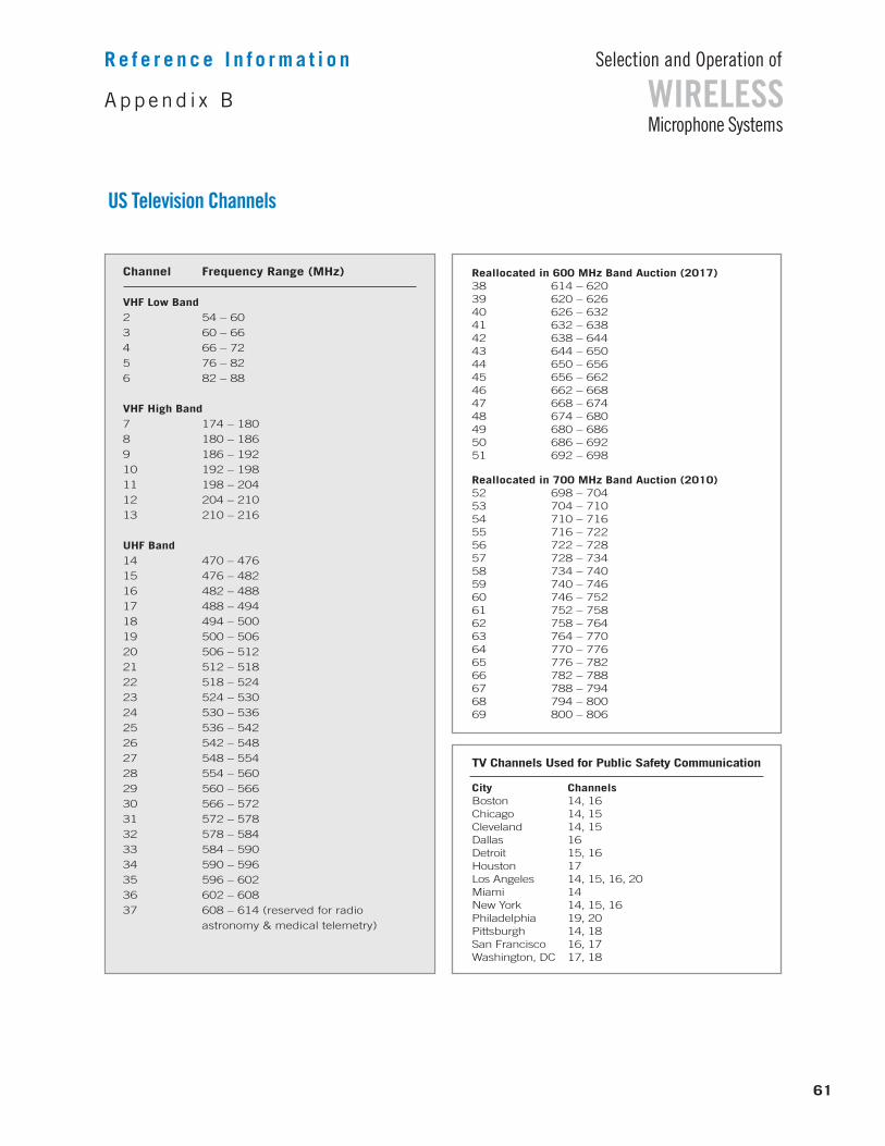
61
WIRELESSSelection and Operation of
Microphone Systems
US Television Channels
Append i x B
R e f e r e n c e I n f o r m a t i o n
Channel Frequency Range (MHz)
VHF Low Band2 54 – 60
3 60 – 66
4 66 – 72
5 76 – 82
6 82 – 88
VHF High Band7 174 – 180
8 180 – 186
9 186 – 192
10 192 – 198
11 198 – 204
12 204 – 210
13 210 – 216
UHF Band14 470 – 476
15 476 – 482
16 482 – 488
17 488 – 494
18 494 – 500
19 500 – 506
20 506 – 512
21 512 – 518
22 518 – 524
23 524 – 530
24 530 – 536
25 536 – 542
26 542 – 548
27 548 – 554
28 554 – 560
29 560 – 566
30 566 – 572
31 572 – 578
32 578 – 584
33 584 – 590
34 590 – 596
35 596 – 602
36 602 – 608
37 608 – 614 (reserved for radio
astronomy & medical telemetry)
Reallocated in 600 MHz Band Auction (2017)38 614 – 62039 620 – 62640 626 – 63241 632 – 63842 638 – 64443 644 – 65044 650 – 65645 656 – 66246 662 – 66847 668 – 67448 674 – 68049 680 – 68650 686 – 69251 692 – 698
Reallocated in 700 MHz Band Auction (2010)52 698 – 70453 704 – 71054 710 – 71655 716 – 72256 722 – 72857 728 – 73458 734 – 74059 740 – 74660 746 – 75261 752 – 75862 758 – 76463 764 – 77064 770 – 77665 776 – 78266 782 – 78867 788 – 79468 794 – 80069 800 – 806
TV Channels Used for Public Safety Communication
City ChannelsBoston 14, 16Chicago 14, 15Cleveland 14, 15Dallas 16Detroit 15, 16Houston 17Los Angeles 14, 15, 16, 20Miami 14New York 14, 15, 16Philadelphia 19, 20Pittsburgh 14, 18San Francisco 16, 17Washington, DC 17, 18
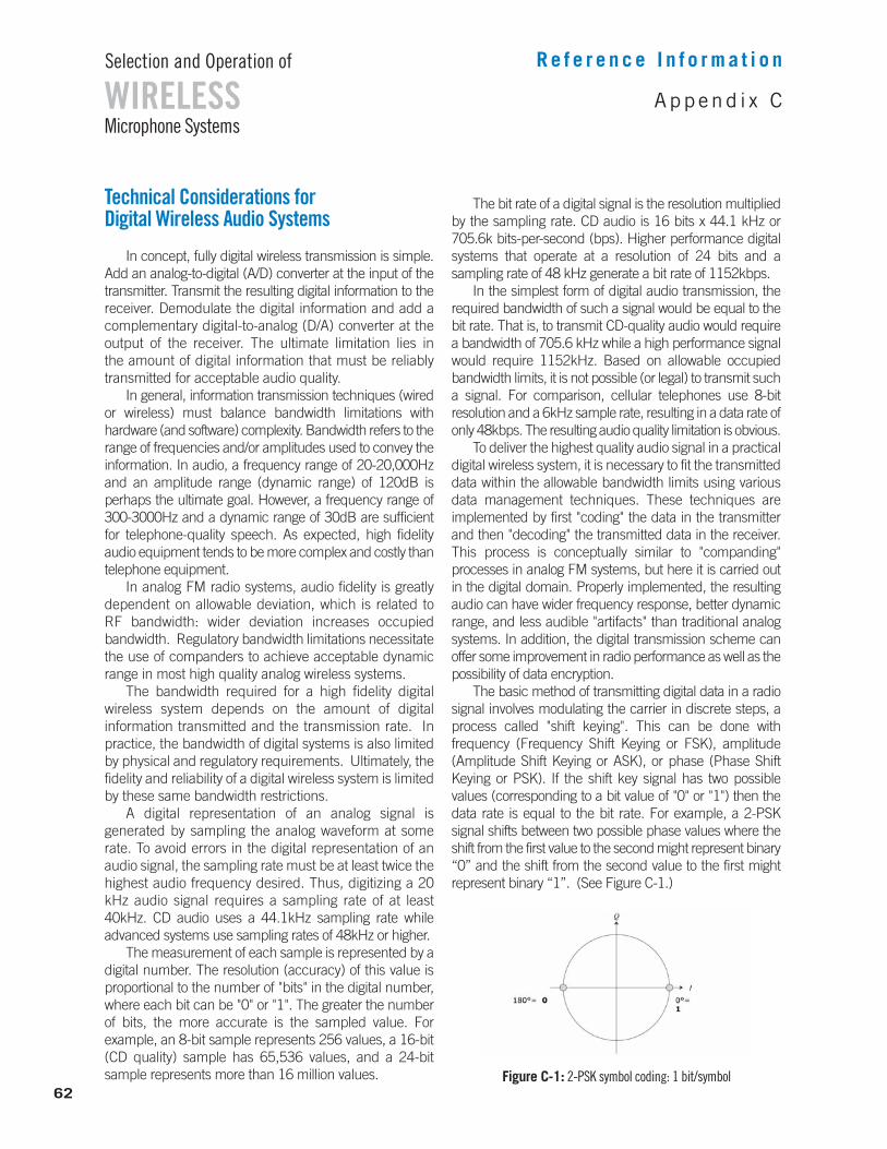
62
WIRELESSSelection and Operation of
Microphone SystemsAppend i x C
R e f e r e n c e I n f o r m a t i o n
Technical Considerations for Digital Wireless Audio Systems
In concept, fully digital wireless transmission is simple.Add an analog-to-digital (A/D) converter at the input of thetransmitter. Transmit the resulting digital information to thereceiver. Demodulate the digital information and add a complementary digital-to-analog (D/A) converter at the output of the receiver. The ultimate limitation lies in the amount of digital information that must be reliably transmitted for acceptable audio quality.
In general, information transmission techniques (wiredor wireless) must balance bandwidth limitations with hardware (and software) complexity. Bandwidth refers to therange of frequencies and/or amplitudes used to convey theinformation. In audio, a frequency range of 20-20,000Hzand an amplitude range (dynamic range) of 120dB is perhaps the ultimate goal. However, a frequency range of300-3000Hz and a dynamic range of 30dB are sufficientfor telephone-quality speech. As expected, high fidelityaudio equipment tends to be more complex and costly thantelephone equipment.
In analog FM radio systems, audio fidelity is greatlydependent on allowable deviation, which is related to RF bandwidth: wider deviation increases occupied bandwidth. Regulatory bandwidth limitations necessitatethe use of companders to achieve acceptable dynamicrange in most high quality analog wireless systems.
The bandwidth required for a high fidelity digital wireless system depends on the amount of digital information transmitted and the transmission rate. Inpractice, the bandwidth of digital systems is also limitedby physical and regulatory requirements. Ultimately, thefidelity and reliability of a digital wireless system is limitedby these same bandwidth restrictions.
A digital representation of an analog signal is generated by sampling the analog waveform at somerate. To avoid errors in the digital representation of anaudio signal, the sampling rate must be at least twice thehighest audio frequency desired. Thus, digitizing a 20kHz audio signal requires a sampling rate of at least40kHz. CD audio uses a 44.1kHz sampling rate while advanced systems use sampling rates of 48kHz or higher.
The measurement of each sample is represented by adigital number. The resolution (accuracy) of this value isproportional to the number of "bits" in the digital number,where each bit can be "0" or "1". The greater the numberof bits, the more accurate is the sampled value. For example, an 8-bit sample represents 256 values, a 16-bit(CD quality) sample has 65,536 values, and a 24-bit sample represents more than 16 million values.
The bit rate of a digital signal is the resolution multipliedby the sampling rate. CD audio is 16 bits x 44.1 kHz or705.6k bits-per-second (bps). Higher performance digitalsystems that operate at a resolution of 24 bits and a sampling rate of 48 kHz generate a bit rate of 1152kbps.
In the simplest form of digital audio transmission, the required bandwidth of such a signal would be equal to thebit rate. That is, to transmit CD-quality audio would requirea bandwidth of 705.6 kHz while a high performance signalwould require 1152kHz. Based on allowable occupiedbandwidth limits, it is not possible (or legal) to transmit sucha signal. For comparison, cellular telephones use 8-bit resolution and a 6kHz sample rate, resulting in a data rate ofonly 48kbps. The resulting audio quality limitation is obvious.
To deliver the highest quality audio signal in a practicaldigital wireless system, it is necessary to fit the transmitteddata within the allowable bandwidth limits using various data management techniques. These techniques are implemented by first "coding" the data in the transmitterand then "decoding" the transmitted data in the receiver.This process is conceptually similar to "companding"processes in analog FM systems, but here it is carried outin the digital domain. Properly implemented, the resultingaudio can have wider frequency response, better dynamicrange, and less audible "artifacts" than traditional analog systems. In addition, the digital transmission scheme canoffer some improvement in radio performance as well as thepossibility of data encryption.
The basic method of transmitting digital data in a radiosignal involves modulating the carrier in discrete steps, aprocess called "shift keying". This can be done with frequency (Frequency Shift Keying or FSK), amplitude (Amplitude Shift Keying or ASK), or phase (Phase Shift Keying or PSK). If the shift key signal has two possible values (corresponding to a bit value of "0" or "1") then thedata rate is equal to the bit rate. For example, a 2-PSK signal shifts between two possible phase values where theshift from the first value to the second might represent binary“0” and the shift from the second value to the first mightrepresent binary “1”. (See Figure C-1.)
Figure C-1: 2-PSK symbol coding: 1 bit/symbol
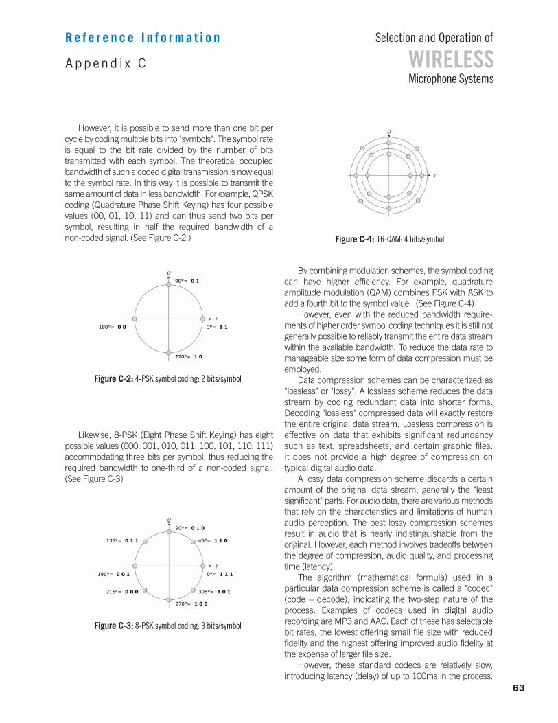
However, it is possible to send more than one bit percycle by coding multiple bits into "symbols". The symbol rateis equal to the bit rate divided by the number of bits transmitted with each symbol. The theoretical occupiedbandwidth of such a coded digital transmission is now equalto the symbol rate. In this way it is possible to transmit thesame amount of data in less bandwidth. For example, QPSKcoding (Quadrature Phase Shift Keying) has four possiblevalues (00, 01, 10, 11) and can thus send two bits per symbol, resulting in half the required bandwidth of a non-coded signal. (See Figure C-2.)
Likewise, 8-PSK (Eight Phase Shift Keying) has eightpossible values (000, 001, 010, 011, 100, 101, 110, 111)accommodating three bits per symbol, thus reducing the required bandwidth to one-third of a non-coded signal. (See Figure C-3)
By combining modulation schemes, the symbol codingcan have higher efficiency. For example, quadrature amplitude modulation (QAM) combines PSK with ASK toadd a fourth bit to the symbol value. (See Figure C-4)
However, even with the reduced bandwidth require-ments of higher order symbol coding techniques it is still notgenerally possible to reliably transmit the entire data streamwithin the available bandwidth. To reduce the data rate tomanageable size some form of data compression must beemployed.
Data compression schemes can be characterized as"lossless" or "lossy". A lossless scheme reduces the datastream by coding redundant data into shorter forms. Decoding "lossless" compressed data will exactly restorethe entire original data stream. Lossless compression iseffective on data that exhibits significant redundancysuch as text, spreadsheets, and certain graphic files. It does not provide a high degree of compression on typical digital audio data.
A lossy data compression scheme discards a certainamount of the original data stream, generally the "least significant" parts. For audio data, there are various methodsthat rely on the characteristics and limitations of humanaudio perception. The best lossy compression schemes result in audio that is nearly indistinguishable from the original. However, each method involves tradeoffs betweenthe degree of compression, audio quality, and processingtime (latency).
The algorithm (mathematical formula) used in a particular data compression scheme is called a "codec"(code – decode), indicating the two-step nature of theprocess. Examples of codecs used in digital audio recording are MP3 and AAC. Each of these has selectablebit rates, the lowest offering small file size with reduced fidelity and the highest offering improved audio fidelity atthe expense of larger file size.
However, these standard codecs are relatively slow, introducing latency (delay) of up to 100ms in the process.
63
WIRELESSSelection and Operation of
Microphone SystemsAppend i x C
R e f e r e n c e I n f o r m a t i o n
Figure C-2: 4-PSK symbol coding: 2 bits/symbol
Figure C-3: 8-PSK symbol coding: 3 bits/symbol
Figure C-4: 16-QAM: 4 bits/symbol
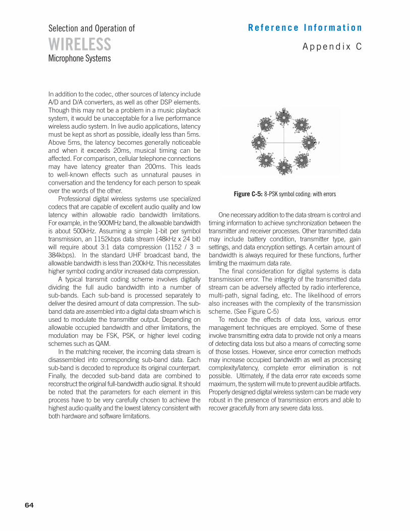
64
WIRELESSSelection and Operation of
Microphone SystemsAppend i x C
R e f e r e n c e I n f o r m a t i o n
In addition to the codec, other sources of latency includeA/D and D/A converters, as well as other DSP elements.Though this may not be a problem in a music playback system, it would be unacceptable for a live performancewireless audio system. In live audio applications, latencymust be kept as short as possible, ideally less than 5ms.Above 5ms, the latency becomes generally noticeableand when it exceeds 20ms, musical timing can be affected. For comparison, cellular telephone connectionsmay have latency greater than 200ms. This leads to well-known effects such as unnatural pauses in conversation and the tendency for each person to speakover the words of the other.
Professional digital wireless systems use specializedcodecs that are capable of excellent audio quality and lowlatency within allowable radio bandwidth limitations. For example, in the 900MHz band, the allowable bandwidthis about 500kHz. Assuming a simple 1-bit per symbol transmission, an 1152kbps data stream (48kHz x 24 bit)will require about 3:1 data compression (1152 / 3 =384kbps). In the standard UHF broadcast band, the allowable bandwidth is less than 200kHz. This necessitateshigher symbol coding and/or increased data compression.
A typical transmit coding scheme involves digitally dividing the full audio bandwidth into a number of sub-bands. Each sub-band is processed separately to deliver the desired amount of data compression. The sub-band data are assembled into a digital data stream which isused to modulate the transmitter output. Depending on allowable occupied bandwidth and other limitations, themodulation may be FSK, PSK, or higher level codingschemes such as QAM.
In the matching receiver, the incoming data stream isdisassembled into corresponding sub-band data. Each sub-band is decoded to reproduce its original counterpart.Finally, the decoded sub-band data are combined to reconstruct the original full-bandwidth audio signal. It shouldbe noted that the parameters for each element in thisprocess have to be very carefully chosen to achieve thehighest audio quality and the lowest latency consistent withboth hardware and software limitations.
One necessary addition to the data stream is control andtiming information to achieve synchronization between thetransmitter and receiver processes. Other transmitted datamay include battery condition, transmitter type, gain settings, and data encryption settings. A certain amount ofbandwidth is always required for these functions, furtherlimiting the maximum data rate.
The final consideration for digital systems is datatransmission error. The integrity of the transmitted datastream can be adversely affected by radio interference,multi-path, signal fading, etc. The likelihood of errors also increases with the complexity of the transmissionscheme. (See Figure C-5)
To reduce the effects of data loss, various error management techniques are employed. Some of these involve transmitting extra data to provide not only a meansof detecting data loss but also a means of correcting someof those losses. However, since error correction methodsmay increase occupied bandwidth as well as processingcomplexity/latency, complete error elimination is not possible. Ultimately, if the data error rate exceeds somemaximum, the system will mute to prevent audible artifacts.Properly designed digital wireless system can be made veryrobust in the presence of transmission errors and able to recover gracefully from any severe data loss.
Figure C-5: 8-PSK symbol coding: with errors
65
WIRELESSSelection and Operation of
Microphone SystemsG l o s s a r y
R e f e r e n c e I n f o r m a t i o n
AbsorptionThe weakening of radio wave strength by losses in various materials
ADCAnalog-to-digital converter, also abbreviated A/D
AFAudio frequencies, typically 20-20,000 Hz.
AMAmplitude modulation
AmbientLocal or background, ie. ambient noise
AmplitudeMagnitude or strength of a signal or wave
AM rejection Ability of an FM receiver to reject signals from AM transmitters and/or AM noise from electrical devices or natural sources
AntennaElectrical circuit element that transmits or receives radio waves
Antenna gainMeasure of antenna efficiency compared to a reference antenna, ie. dBi =gain relative to theoretical isotropic (spherical omnidirectional) antenna
Antenna splitterA device for electrically matching a single antenna to multiple receivers
ASKAmplitude shift keying
AttenuationMeasure of the loss of amplitude of a signal
BandA defined portion of the frequency spectrum
BandwidthA measure of the frequency range of a signal or device
Base frequencyThe actual frequency of a crystal oscillator, usually then multiplied to some higher operating frequency
Bias voltageA fixed DC voltage which establishes the operating characteristic of a circuit element such as a transistor
BitSmallest digital data element, has a value of "0" or "1"
BodypackTransmitter style which can be worn on the body
CaptureThe effect of a strong FM signal suppressing weaker signals at the receiver
CarrierThe basic or unmodulated radio wave
CascadeActive antenna output port of receiver or antenna splitter than can feedanother receiver or antenna splitter
CodecSoftware algorithm for data compression and decompression (code-decode)
CompanderA two-step noise reduction system consisting of a compressor in the transmitter and an expander in the receiver
CompressorA circuit which reduces the dynamic range of a signal by a fixed ratio, typically 2:1 in a compander system
DACDigital-to-analog converter, also abbreviated D/A
dBmRatio of power levels relative to one milliwatt, ie. 0dBm = 1mW, 10dBm = 10mW
DECTDigital Enhanced Cordless Telecommunications, standard for digital cordless telephones, ie. 1920-1930 MHz in the US, different bands inother countries
De-emphasisA fixed equalization which typically rolls off high frequencies in the second step of a two-step noise reduction process
DemodulationThe recovery of the original modulating information from a radio signal
DetectorThe circuitry that performs demodulation
DeviationThe maximum frequency variation of an FM signal
DiffractionThe bending or partial reflection of radio waves by metal objects
DipoleAn antenna which is made up of two active elements
DirectNot reflected
Direct sequence spreadingSpread spectrum technique using continuous, synchronized deviationchanges across a wide frequency range
DistortionAny unwanted difference between the original and final version of a signal
DiversityScheme that relies on statistical decorrelation of the same signal received at multiple locations to minimize signal fading and multipathdropout, also called space diversity or antenna diversity
DropoutThe complete loss of received signal due to multipath interference
DSPDigital Signal Processor, used in digital and hybrid radio circuits
Dynamic rangeMaximum amplitude range of a signal or device, generally the differencebetween the strongest and weakest signals that occur or that the devicecan handle
EncryptionEncoding a transmitted signal so that it can be decoded only with aunique digital "key"
EMElectromagnetic
ERPEffective radiated power, the actual power radiated by a transmitter antenna
ExpanderA circuit which expands the dynamic range of a signal by a finite ratio, typically 1:2 in a compander system
FadingLoss of signal strength due to distance or obstacles in the signal path
FCCFederal Communications Commission, US radio regulatory agency
FieldA distribution of energy in space, ie. electric, magnetic, sound
Field strengthThe amplitude of a field at a given point, measured in volts per meter for electric energy
FMFrequency modulation
FrequencyA measure of the rate of variation of a wave or signal
Frequency agileHaving the ability to change frequencies: tunable
Frequency diversityScheme that relies on statistical decorrelation of the same signal transmittedand received at multiple frequencies to minimize RF interference effects
Frequency hoppingSpread spectrum technique using continuous, synchronized frequencychanges across a wide frequency range
Frequency responseVariation in amplitude of a signal over a range of frequencies
Front endInitial filter stage of a receiver
FSKFrequency shift keying
GainAmplification
GeolocationAbility of a TVBD to determine its geographic location
Ground planeElectrical approximation of a zero-potential reflective surface at the base of an antenna
GSMGlobal Systems for Mobile Communications, mobile telephone standard,ie. 850 Mz and 1900 MHz in the US, different bands in other countries
HandheldTransmitter type which can be held in the hand
HashA term for audible radio interference
HelicalWideband directional antenna consisting of a single circularly-polarized element
HeterodyneTo combine signals of various frequency in a manner that produces additional signals at frequencies which are sums and differences of theoriginal frequencies
HybridRadio design combining digital audio processing with analog transmission
IEMIn ear monitor
IFIntermediate frequency, a lower radio frequency (typically 10.7 MHz)found in the middle stages of a receiver
IFBInterruptible fold back, a cueing system used in broadcast
IF filterA narrow, band-pass filter tuned to the intermediate frequency (IF)
IMIntermodulation, frequencies produced by combinations of other frequencies in non-linear devices
IMDIntermodulation distortion (another name for IM)
IM rejection Ability of a receiver to reject IM products
ImageAn interfering frequency which differs from the desired frequency bytwice the intermediate frequency (IF)
Image rejectionThe ability of a receiver to reject interference from an image frequency (determined by the front end)
ImpedanceA measure of the resistance to current flow in a circuit (may vary with frequency)
IndirectReflected or diffracted
Intercept (third order)A measure of the ability of a radio input stage to handle high signal levelswithout overload or distortion
Inverse square lawMathematical relationship in which one quantity is inversely proportionalto the square of another quantity, ie. signal strength decreases accordingto the distance squared
LatencySignal delay that occurs in digital systems due to finite speed of DSP,ADC, and DAC circuits
LevelThe amplitude or strength of a signal
LFLow frequency
LimiterA circuit which limits the maximum level of a signal
Line-of-sightPreferred wireless operating condition where transmit antenna is visible to receive antenna with no obstruction
LOLocal oscillator, in a receiver it is tuned to a frequency which is offset from the operating frequency by an amount equal to the intermediate frequency (IF)
Log periodicWideband directional antenna consisting of multiple logarithmic-spaceddipole elements
LossDecrease in signal strength during transmission, propagation or reception
MediumSubstance through which a wave propagates; for radio it may be vacuum,gas, liquid or solid; wave speed is affected by medium
MixerCircuitry in a receiver that combines the received signal with the local oscillator to produce the IF signal
Modulating frequencyThe frequency of the audio signal used for modulation of the radio wave
ModulationVariation of a wave parameter (such as amplitude or frequency) to carryinformation
Modulation noiseLow level noise which accompanies the audio signal in a companded wireless microphone system
MultipathReflection of radio waves that causes fluctuation in received signal strength
Narrow bandAn FM signal in which the deviation is much less than the modulating frequency
G l o s s a r y
R e f e r e n c e I n f o r m a t i o n
Microphone Systems
Selection and Operation of
WIRELESS
66
G l o s s a r y
R e f e r e n c e I n f o r m a t i o n
Microphone Systems
Selection and Operation of
WIRELESS
67
NoiseUndesirable random audio or radio energy
Operating frequencyThe final output frequency of a transmitter or the tuned frequency of a receiver
OscillatorA circuit that produces a continuous periodic output
Phase-lock-loop (PLL) A circuit which maintains a desired frequency by means of a self-correcting feedback technique
Plug-onA transmitter type which may be attached directly to a microphone
PMPhase modulation
Point-to-pointTransmission of signal from one fixed location to another fixed location
PolarizationThe orientation of the electric field component of a radio wave
PowerUsually refers to the RF power delivered to the transmitter antenna, measured in milliwatts (mW)
Pre-emphasisA fixed equalization which typically boosts high frequencies in the first part of a two-step noise reduction process
PropagationAbility of radio signal to travel a significant distance
Protected channelsDesignated TVBD-free TV channels at a given location, defined by FCC rules
PSKPhase shift keying
QPSKQuadrature Phase Shift Key, a digital transmission symbol coding with four possible values
QuadraturePhase relationship of 900 between two signals
QuietingThe suppression of radio noise in a receiver when the desired signal ispicked up at a certain strength
Radio wavesElectromagnetic waves which propagate a significant distance from thesource
RCVAbbreviation for Receiver
ReceiverDevice which is sensitive to radio signals and recovers information from them
ReciprocalProperty of a passive antenna to operate equivalently either in transmit orin receive mode
ReflectionRetransmission of incident radio waves by metal objects
RFRadio frequency, generally taken to mean well above 20,000 Hz
RFIRadio frequency interference
SamplingConversion of a continuous audio waveform into discrete digital values
SelectivityMeasure of a receiver’s ability to discriminate between closely-spaced frequencies
SensitivityMeasure of a receiver’s ability to respond to weak radio signals
ShadowBlocking of radio waves by reflective or absorptive (lossy) objects
Shift keyingModulation of a radio wave in discrete steps, used for digital signal transmission
Signal-to-noise ratioOverall useable amplitude range of a signal or device, generally the difference between some reference level and the residual noise level
SINADA measure of receiver sensitivity stated as the RF signal strength required for given minimum signal-to-noise + distortion ratio
Spread spectrumA radio transmission technique which spreads the energy of the signalover a wide frequency range rather than concentrating it at one frequency
Spurious emissions (spur)Residual output from crystal-controlled transmitters occurring at frequencies that are offset from the operating frequency by multiples ofthe crystal base frequency
Spurious rejectionThe ability of a receiver to reject spurious emissions
SquelchCircuit in a receiver that mutes the audio output in the absence of the desired transmitter signal
SpectrumA range of discrete frequencies
STLStudio Transmitter Link, in the US: 944-952 MHz
SuperheterodyneIn a receiver, the technique of filtering the received signal to eliminate possible image frequencies and then mixing the received signal frequencywith the local oscillator (LO) to produce the intermediate frequency (IF)
SymbolDigital data element that contains more than one bit, ie. a QPSK symbol contains two bits
TransmitterDevice which converts information to a radio signal
TVBDTelevision Band Device, sometimes called White Space Device
TXAbbreviation for transmitter
UHFUltra high frequency (about 300 - 3000 MHz)
VCAVoltage controlled amplifier, used in audio compressor and expander circuits
VCOVoltage controlled oscillator, used in radio tuning circuits
VHFVery high frequency (about 30 - 300 MHz)
WavelengthThe physical distance between successive complete cycles of a wave, inversely proportional to frequency, dependent on properties of medium
White SpaceUnoccupied space between active TV channels
WidebandAn FM signal in which the deviation is much greater than the modulatingfrequency
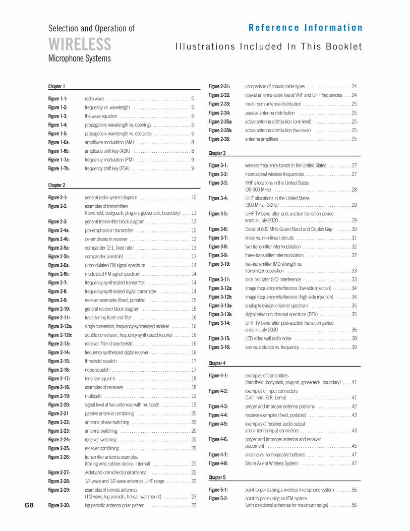
I l lustrat ions Included In This Booklet
R e f e r e n c e I n f o r m a t i o n
Microphone Systems
Selection and Operation of
WIRELESS
68
Chapter 1
Figure 1-1: radio wave . . . . . . . . . . . . . . . . . . . . . . . . . . . . . . . . . . . . . . 5
Figure 1-2: frequency vs. wavelength . . . . . . . . . . . . . . . . . . . . . . . . . . 5
Figure 1-3: the wave equation . . . . . . . . . . . . . . . . . . . . . . . . . . . . . . . . 6
Figure 1-4: propagation: wavelength vs. openings . . . . . . . . . . . . . . . . . 6
Figure 1-5: propagation: wavelength vs. obstacles . . . . . . . . . . . . . . . . . 6
Figure 1-6a: amplitude modulation (AM) . . . . . . . . . . . . . . . . . . . . . . . . . 8
Figure 1-6b: amplitude shift key (ASK) . . . . . . . . . . . . . . . . . . . . . . . . . . 8
Figure 1-7a: frequency modulation (FM) . . . . . . . . . . . . . . . . . . . . . . . . . 9
Figure 1-7b: frequency shift key (FSK) . . . . . . . . . . . . . . . . . . . . . . . . . . . 9
Chapter 2
Figure 2-1: general radio system diagram . . . . . . . . . . . . . . . . . . . . . . . 10
Figure 2-2: examples of transmitters (handheld, bodypack, plug-on, gooseneck, boundary) . . . . 11
Figure 2-3: general transmitter block diagram . . . . . . . . . . . . . . . . . . . . 12
Figure 2-4a: pre-emphasis in transmitter . . . . . . . . . . . . . . . . . . . . . . . . . 12
Figure 2-4b: de-emphasis in receiver . . . . . . . . . . . . . . . . . . . . . . . . . . . . 12
Figure 2-5a: compander (2:1, fixed rate) . . . . . . . . . . . . . . . . . . . . . . . . . 13
Figure 2-5b: compander (variable) . . . . . . . . . . . . . . . . . . . . . . . . . . . . . . 13
Figure 2-6a: unmodulated FM signal spectrum . . . . . . . . . . . . . . . . . . . 14
Figure 2-6b: modulated FM signal spectrum . . . . . . . . . . . . . . . . . . . . . . 14
Figure 2-7: frequency-synthesized transmitter . . . . . . . . . . . . . . . . . . . . 14
Figure 2-8: frequency-synthesized digital transmitter . . . . . . . . . . . . . . 14
Figure 2-9: receiver examples (fixed, portable) . . . . . . . . . . . . . . . . . . . 15
Figure 2-10: general receiver block diagram . . . . . . . . . . . . . . . . . . . . . . 15
Figure 2-11: track tuning front-end filter . . . . . . . . . . . . . . . . . . . . . . . . . . 16
Figure 2-12a: single conversion, frequency-synthesized receiver . . . . . . . . . 16
Figure 2-12b: double conversion, frequency-synthesized receiver . . . . . . . . 16
Figure 2-13: receiver, filter characteristic . . . . . . . . . . . . . . . . . . . . . . . . . 16
Figure 2-14: frequency synthesized digital receiver . . . . . . . . . . . . . . . . . . . 16
Figure 2-15: threshold squelch . . . . . . . . . . . . . . . . . . . . . . . . . . . . . . . . 17
Figure 2-16: noise squelch . . . . . . . . . . . . . . . . . . . . . . . . . . . . . . . . . . . . 17
Figure 2-17: tone key squelch . . . . . . . . . . . . . . . . . . . . . . . . . . . . . . . . . 18
Figure 2-18: examples of receivers . . . . . . . . . . . . . . . . . . . . . . . . . . . . . 18
Figure 2-19: multipath . . . . . . . . . . . . . . . . . . . . . . . . . . . . . . . . . . . . . . . 19
Figure 2-20: signal level at two antennas with multipath . . . . . . . . . . . . . 19
Figure 2-21 passive antenna combining . . . . . . . . . . . . . . . . . . . . . . . . . 20
Figure 2-22: antenna phase switching . . . . . . . . . . . . . . . . . . . . . . . . . . . 20
Figure 2-23: antenna switching . . . . . . . . . . . . . . . . . . . . . . . . . . . . . . . . 20
Figure 2-24: receiver switching . . . . . . . . . . . . . . . . . . . . . . . . . . . . . . . . 20
Figure 2-25: receiver combining . . . . . . . . . . . . . . . . . . . . . . . . . . . . . . . 20
Figure 2-26: transmitter antenna examples (trailing wire, rubber-duckie, internal) . . . . . . . . . . . . . . . . . 21
Figure 2-27: wideband omnidirectional antenna . . . . . . . . . . . . . . . . . . . 22
Figure 2-28: 1/4 wave and 1/2 wave antennas UHF range . . . . . . . . . . . 22
Figure 2-29: examples of remote antennas (1/2 wave, log periodic, helical, wall mount) . . . . . . . . . . . . 23
Figure 2-30: log periodic antenna polar pattern . . . . . . . . . . . . . . . . . . . . 23
Figure 2-31: comparison of coaxial cable types . . . . . . . . . . . . . . . . . . . . 24
Figure 2-32: coaxial antenna cable loss at VHF and UHF frequencies . . . 24
Figure 2-33: multi-room antenna distribution . . . . . . . . . . . . . . . . . . . . . . 25
Figure 2-34: passive antenna distribution . . . . . . . . . . . . . . . . . . . . . . . . 25
Figure 2-35a: active antenna distribution (one level) . . . . . . . . . . . . . . . . . 25
Figure 2-35b: active antenna distribution (two level) . . . . . . . . . . . . . . . . . 25
Figure 2-36: antenna amplifiers . . . . . . . . . . . . . . . . . . . . . . . . . . . . . . . . 25
Chapter 3
Figure 3-1: wireless frequency bands in the United States . . . . . . . . . . 27
Figure 3-2: international wireless frequencies . . . . . . . . . . . . . . . . . . . . . 27
Figure 3-3: VHF allocations in the United States (30-300 MHz) . . . . . . . . . . . . . . . . . . . . . . . . . . . . . . . . . . . 28
Figure 3-4: UHF allocations in the United States (300 MHz - 3GHz) . . . . . . . . . . . . . . . . . . . . . . . . . . . . . . . . 29
Figure 3-5: UHF TV band after post-auction transition period ends in July 2020 . . . . . . . . . . . . . . . . . . . . . . . . . . . . . . . . . 29
Figure 3-6: Detail of 600 MHz Guard Band and Duplex Gap . . . . . . . 30
Figure 3-7: linear vs. non-linear circuits . . . . . . . . . . . . . . . . . . . . . . . . . 31
Figure 3-8: two-transmitter intermodulation . . . . . . . . . . . . . . . . . . . . . . 32
Figure 3-9: three-transmitter intermodulation . . . . . . . . . . . . . . . . . . . . 32
Figure 3-10: two-transmitter IMD strength vs. transmitter separation . . . . . . . . . . . . . . . . . . . . . . . . . . . . . 33
Figure 3-11: local oscillator (LO) interference . . . . . . . . . . . . . . . . . . . . . . 33
Figure 3-12a: image frequency interference (low-side injection) . . . . . . . . 34
Figure 3-12b: image frequency interference (high-side injection) . . . . . . . 34
Figure 3-13a: analog television channel spectrum . . . . . . . . . . . . . . . . . . 35
Figure 3-13b: digital television channel spectrum (DTV) . . . . . . . . . . . . . . 35
Figure 3-14: UHF TV band after post-auction transition period ends in July 2020 . . . . . . . . . . . . . . . . . . . . . . . . . . . . . . . . 36
Figure 3-15: LED video wall radio noise . . . . . . . . . . . . . . . . . . . . . . . . . . 38
Figure 3-16: loss vs. distance vs. frequency . . . . . . . . . . . . . . . . . . . . . . . 39
Chapter 4
Figure 4-1: examples of transmitters (handheld, bodypack, plug-on, gooseneck, boundary) . . . . 41
Figure 4-2: examples of input connectors (1/4”, mini XLR, Lemo) . . . . . . . . . . . . . . . . . . . . . . . . . . . . 41
Figure 4-3: proper and improper antenna positions . . . . . . . . . . . . . . . 42
Figure 4-4: receiver examples (fixed, portable) . . . . . . . . . . . . . . . . . . . 43
Figure 4-5: examples of receiver audio output and antenna input connectors . . . . . . . . . . . . . . . . . . . . . . . 43
Figure 4-6: proper and improper antenna and receiver placement . . . . . . . . . . . . . . . . . . . . . . . . . . . . . . . . . . . . . . 45
Figure 4-7: alkaline vs. rechargeable batteries . . . . . . . . . . . . . . . . . . . . 47
Figure 4-8: Shure Axient Wireless System . . . . . . . . . . . . . . . . . . . . . . . 47
Chapter 5
Figure 5-1: point-to-point using a wireless microphone system . . . . . . . 56
Figure 5-2: point-to-point using an IEM system(with directional antennas for maximum range) . . . . . . . . . 56
69
WIRELESSSelection and Operation of
Microphone SystemsB i o g r aph y
R e f e r e n c e I n f o r m a t i o n
Tim is a native of the south side of Chicago (Go White
Sox!). A lifelong interest in both entertainment and science
has led to the field of audio as his choice for combining
these interests in a useful way. Prior to joining Shure he
worked as an engineer for recording, radio and live sound,
operated his own recording studio and sound company,
and continues to play music professionally. He holds a BS
degree in Aeronautical and Astronautical Engineering,
with a minor in Electrical Engineering, from the University
of Illinois, Urbana-Champaign. While at the University,
Tim also worked as chief technician with both the Speech
and Hearing Science and Linguistics departments.
Since joining Shure in 1984, Tim has served in
a technical support and training capacity for multiple
departments. He has been active in product and
applications education for Shure customers, dealers, and
installers, as well as company staff. His major goal has
been to increase the understanding of quality audio by
presenting technical information in a way that is thorough
but still very accessible. Tim's particular emphasis is on
the contribution of proper selection and technique for
both wired and wireless microphones.
In addition, Tim has done technical presentations for
many industry organizations (NAB, NAMM, AES, and
SBE), as well as for US government entities such as
the White House Communication Agency and the US
Air Force. Through His international assignments he has
been fortunate to be able to deliver presentations in more
than twenty countries and on all but one of the continents
(still waiting for an offer from Antarctica...).
He has provided specific applications assistance to
various performing artists including the Rolling Stones and
U2, for theme parks such as Disney and Universal
Studios, and performance groups such as Cirque du Soleil.
While at Shure, Tim has authored several educational
booklets including "Selection and Operation of Wireless
Microphone Systems" and "Audio Systems Guide for
Houses of Worship."
His articles have also appeared in Recording Engineer
Producer, Live Sound Magazine, Pro AV, Technologies for
Worship, and Church Sound Magazine.
BIOGRAPHY: Tim Vear
I would like to cite the following individuals at Shure Inc. for their extreme patience and invaluable assistance:Chris Lyons
Edgar Reihl
Ahren Hartman
Davida Rochman
(and Stuart Baum, too!)
Thanks a ton!
Additional Shure Publications Available:
Printed or electronic versions of the following guides are available free of charge.
To obtain your complimentary copies, call one of the phone numbers listed below
or visit www.shure.com.
• Selection and Operation of Personal Monitor Systems
• Audio Systems Guide for Houses of Worship
• Microphone Techniques for Studio Recording
• Microphone Techniques for Live Sound Reinforcement
Our Dedication to Quality Products
Shure offers a complete line of microphones and wireless microphone systems for everyone
from first-time users to professionals in the music industry–for nearly every possible application.
For over nine decades, the Shure name has been synonymous with quality audio.
All Shure products are designed to provide consistent, high-quality performance under the
most extreme real-life operating conditions.
©2017 Shure Incorporated AL25573B 2.5M 5/17
Asia, Pacific:Shure Asia Limited
22/F, 625 King’s Road
North Point, Island East
Hong Kong
Phone: +852-2893-4290
Fax: +852-2893-4055
Email: [email protected]
www.shureasia.com
United States, Canada, Latin America, Caribbean:Shure Incorporated
5800 West Touhy Avenue
Niles, IL 60714-4608 USA
Phone: +1 847-600-2000
Fax: +1 847-600-1212 (USA)
Fax: +1 847-600-6446
Email: [email protected]
www.shure.com©2013 Shure Incorporated
Europe, Middle East, Africa:Shure Europe GmbH
Jakob-Dieffenbacher-Str. 12,
75031 Eppingen, Germany
Phone: +49-7262-92490
Fax: +49-7262-9249114
Email: [email protected]
www.shure.eu