Embed Size (px)
Citation preview
Selecting Appropriate Stormwater Control Measures for Your Development Project
Jill Bicknell, P.E., EOA, Inc.
Phase II Post-Construction Stormwater Requirements Workshop - February 10, 2014

Outline of Presentation Strategy for Incorporating LID into Projects
Small (Tier 1) Projects – Site Design
Tier 2 and 3 Projects• Site Design to Reduce Runoff
• Treatment Measure Options
• Runoff Retention Approaches
• Addressing Peak Management
Pollutant Source Controls
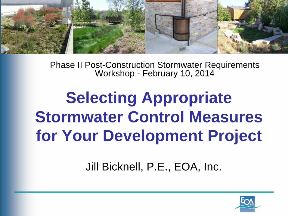
Low Impact Development (LID) Reduce runoff and mimic a site’s predevelopment
hydrology:• Minimize disturbed areas and impervious surfaces• Use infiltration, evapotranspiration, or rainwater
harvesting to retain and treat stormwater runoff• Use biotreatment where these methods are infeasible
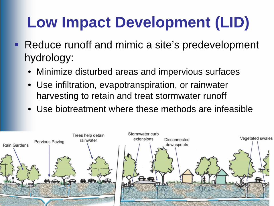
Integrating LID into a ProjectPlan & design stormwater controls integrally with the site plan and landscaping for the project
Lay out site to protect/preserve natural areas and drainage patterns
Delineate drainage management areas (DMAs) Develop stormwater control plan to take
advantage of vegetated areas for infiltration Locate and size LID facilities
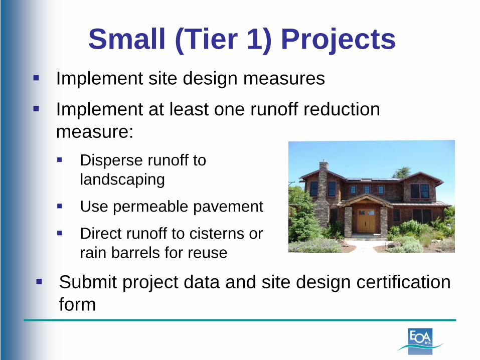
Small (Tier 1) Projects Implement site design measures Implement at least one runoff reduction
measure: Disperse runoff to
landscaping
Use permeable pavement
Direct runoff to cisterns or rain barrels for reuse
Submit project data and site design certification form
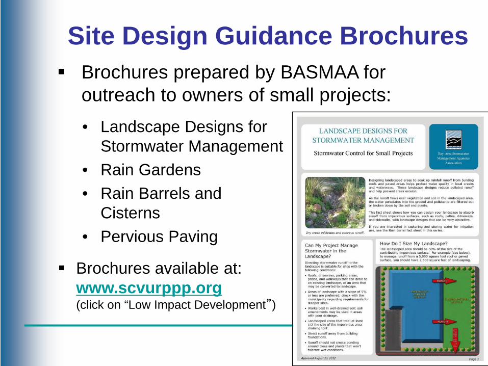
Brochures prepared by BASMAA for outreach to owners of small projects:• Landscape Designs for
Stormwater Management• Rain Gardens• Rain Barrels and
Cisterns• Pervious Paving
Brochures available at:www.scvurppp.org(click on “Low Impact Development”)
Site Design Guidance Brochures

Tier 2 and Tier 3 Projects
Self-Treating Areas Self-Retaining Areas
Use site design approaches to reduce the amount of runoff that must be treated/retained
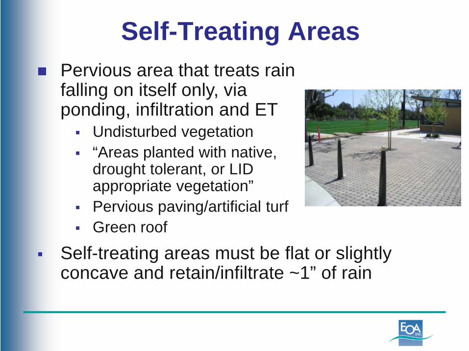
Self-Treating Areas Pervious area that treats rain
falling on itself only, via ponding, infiltration and ET Undisturbed vegetation “Areas planted with native,
drought tolerant, or LID appropriate vegetation”
Pervious paving/artificial turf Green roof
Self-treating areas must be flat or slightly concave and retain/infiltrate ~1” of rain
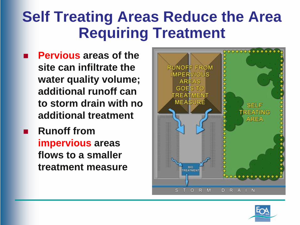
Self Treating Areas Reduce the Area Requiring Treatment
Pervious areas of the site can infiltrate the water quality volume; additional runoff can to storm drain with no additional treatment
Runoff fromimpervious areas flows to a smaller treatment measure
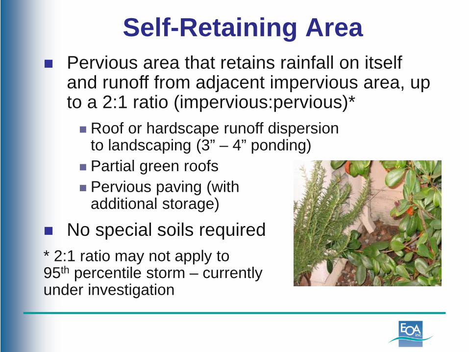
Self-Retaining Area Pervious area that retains rainfall on itself
and runoff from adjacent impervious area, up to a 2:1 ratio (impervious:pervious)* Roof or hardscape runoff dispersion
to landscaping (3” – 4” ponding) Partial green roofs Pervious paving (with
additional storage)
No special soils required* 2:1 ratio may not apply to 95th percentile storm – currentlyunder investigation

Self-Retaining Areas Reduce the Area that Requires Treatment Runoff from impervious
portions of the project can flow directly to a pervious area that is at least 50% of the size of the contributing area
Runoff from other impervious areas flows to smaller treatment measure
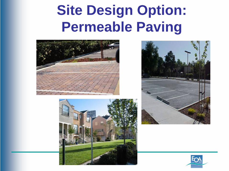
Site Design Option:Permeable Paving
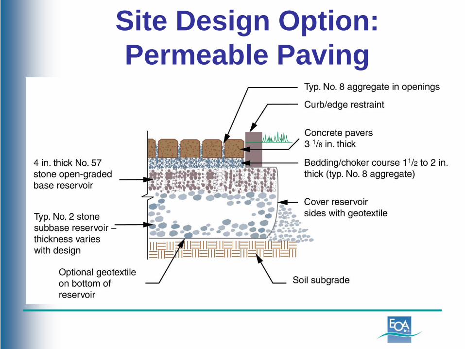
Site Design Option:Permeable Paving
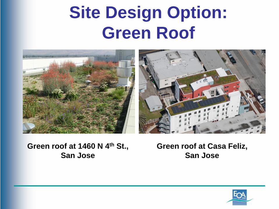
Site Design Option:Green Roof
Green roof at Casa Feliz,San Jose
Green roof at 1460 N 4th St.,San Jose
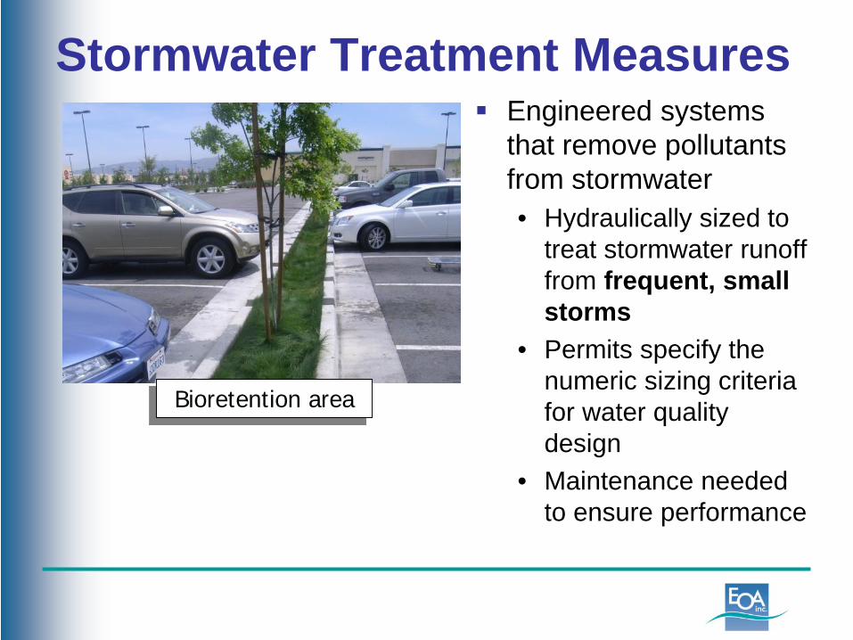
Stormwater Treatment Measures Engineered systems
that remove pollutants from stormwater• Hydraulically sized to
treat stormwater runoff from frequent, small storms
• Permits specify the numeric sizing criteria for water quality design
• Maintenance needed to ensure performance
Bioretention area
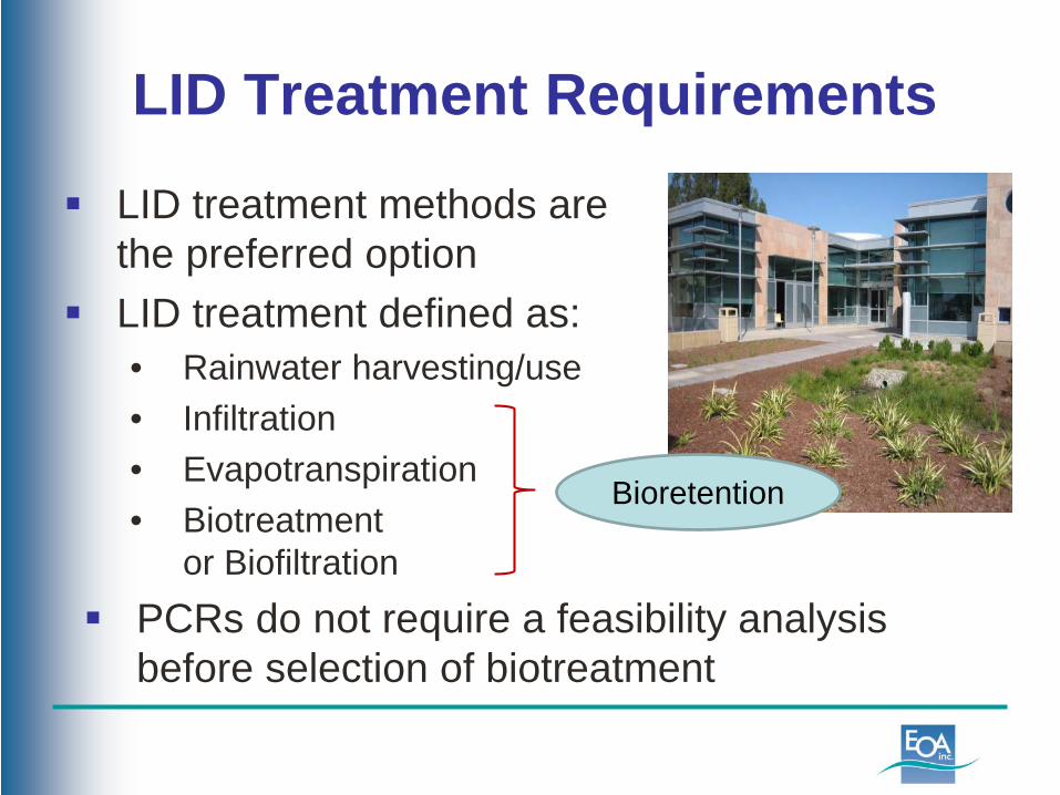
LID Treatment Requirements
LID treatment methods are the preferred option
LID treatment defined as:• Rainwater harvesting/use • Infiltration • Evapotranspiration • Biotreatment
or Biofiltration PCRs do not require a feasibility analysis
before selection of biotreatment
Bioretention
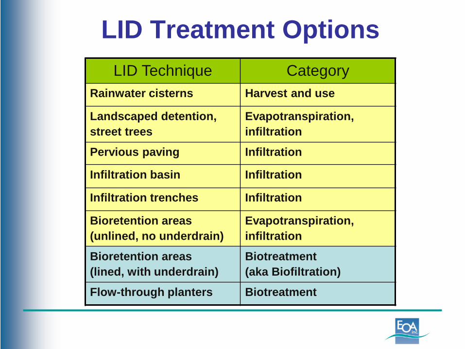
LID Treatment OptionsLID Technique Category
Rainwater cisterns Harvest and use
Landscaped detention, street trees
Evapotranspiration, infiltration
Pervious paving Infiltration
Infiltration basin Infiltration
Infiltration trenches Infiltration
Bioretention areas (unlined, no underdrain)
Evapotranspiration, infiltration
Bioretention areas (lined, with underdrain)
Biotreatment(aka Biofiltration)
Flow-through planters Biotreatment
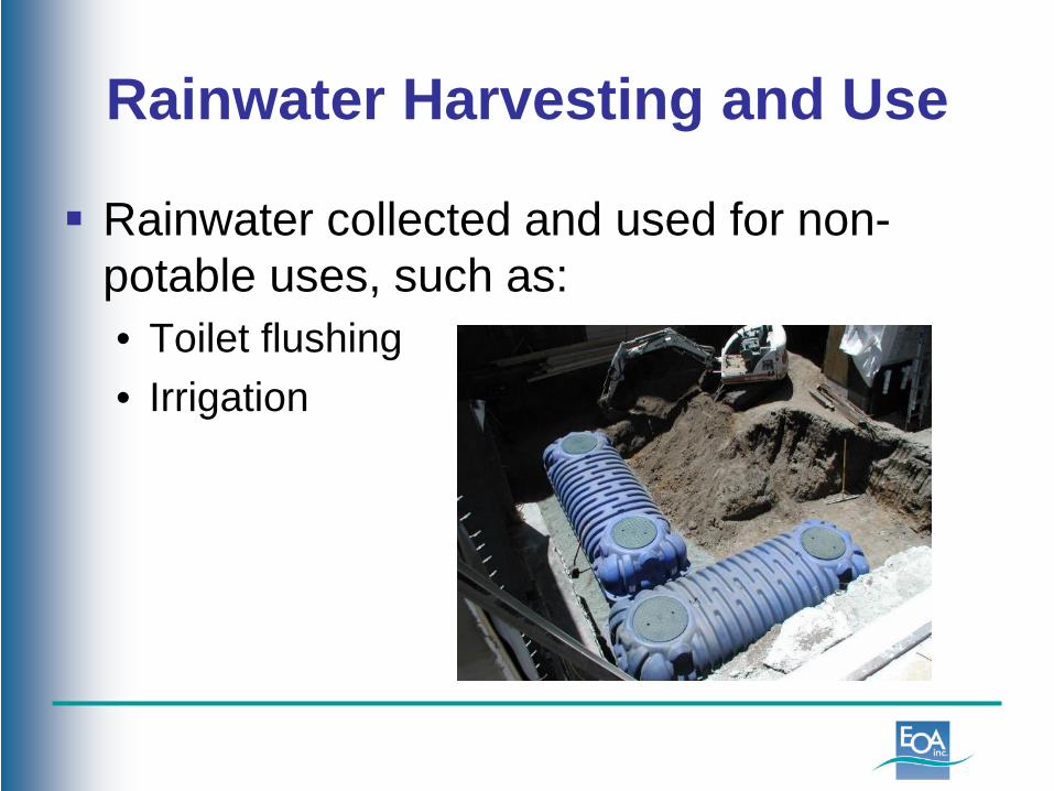
Rainwater Harvesting and Use
Rainwater collected and used for non-potable uses, such as:• Toilet flushing• Irrigation

Rainwater Harvesting
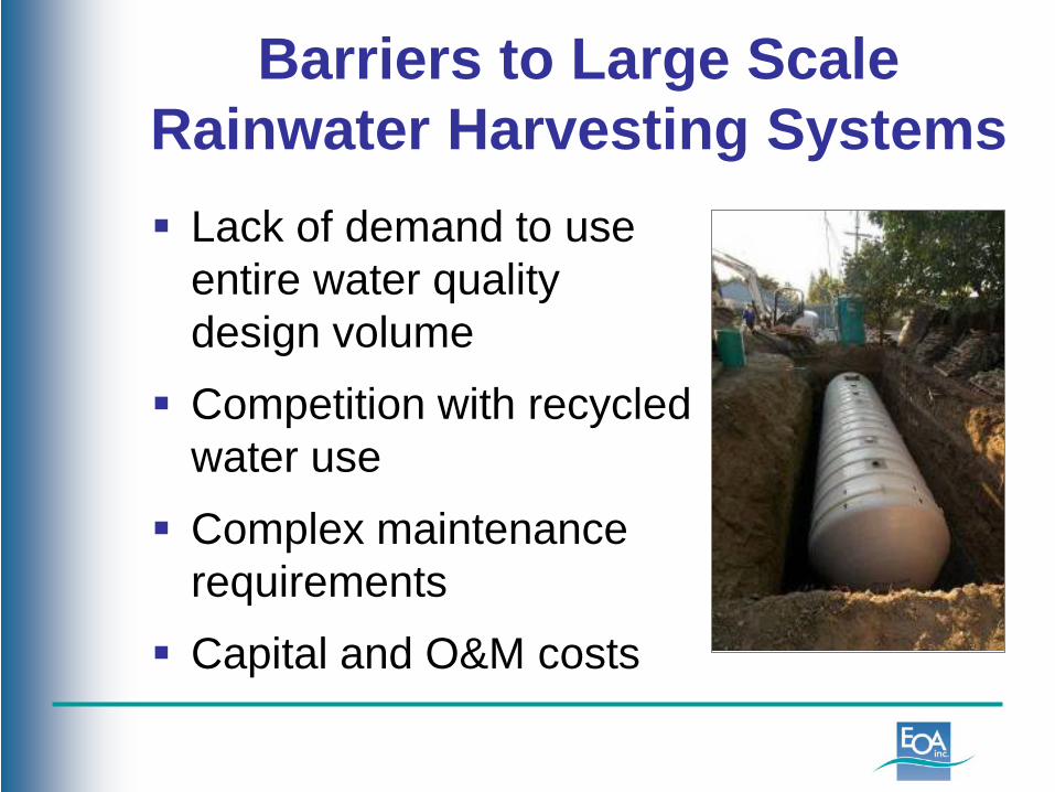
Barriers to Large ScaleRainwater Harvesting Systems Lack of demand to use
entire water qualitydesign volume
Competition with recycledwater use
Complex maintenancerequirements
Capital and O&M costs
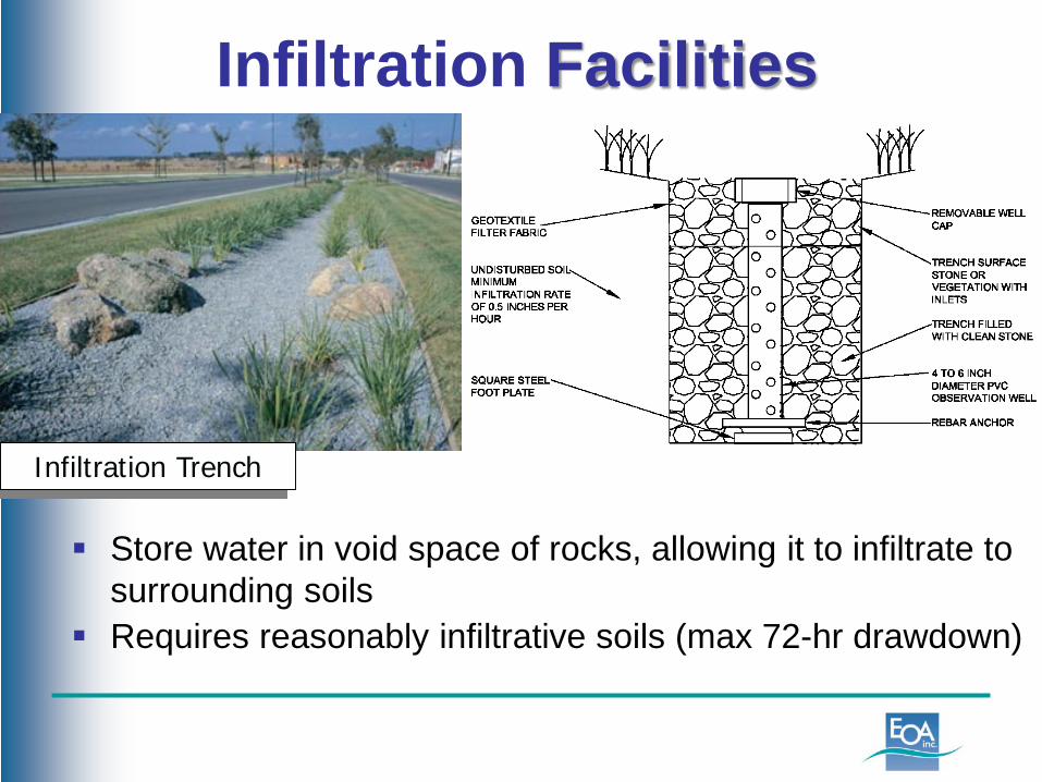
Infiltration Facilities
Store water in void space of rocks, allowing it to infiltrate to surrounding soils
Requires reasonably infiltrative soils (max 72-hr drawdown)
Infiltration Trench

Infiltration Trenches
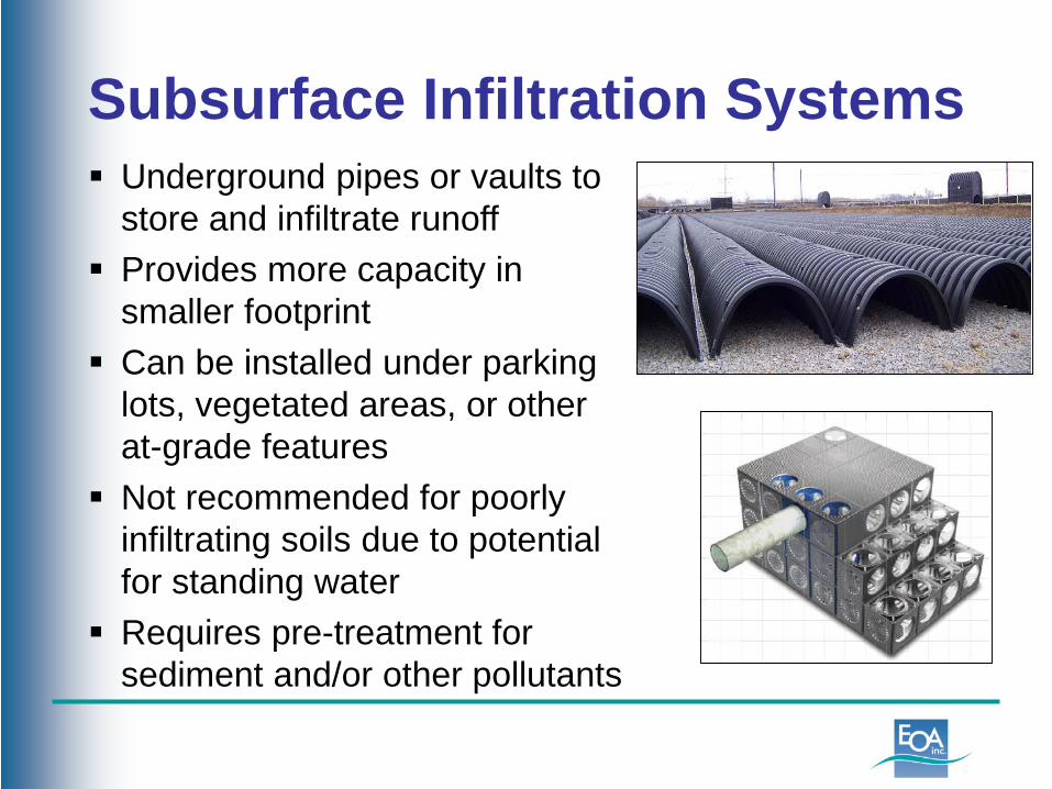
Subsurface Infiltration Systems Underground pipes or vaults to
store and infiltrate runoff Provides more capacity in
smaller footprint Can be installed under parking
lots, vegetated areas, or other at-grade features
Not recommended for poorly infiltrating soils due to potential for standing water
Requires pre-treatment for sediment and/or other pollutants
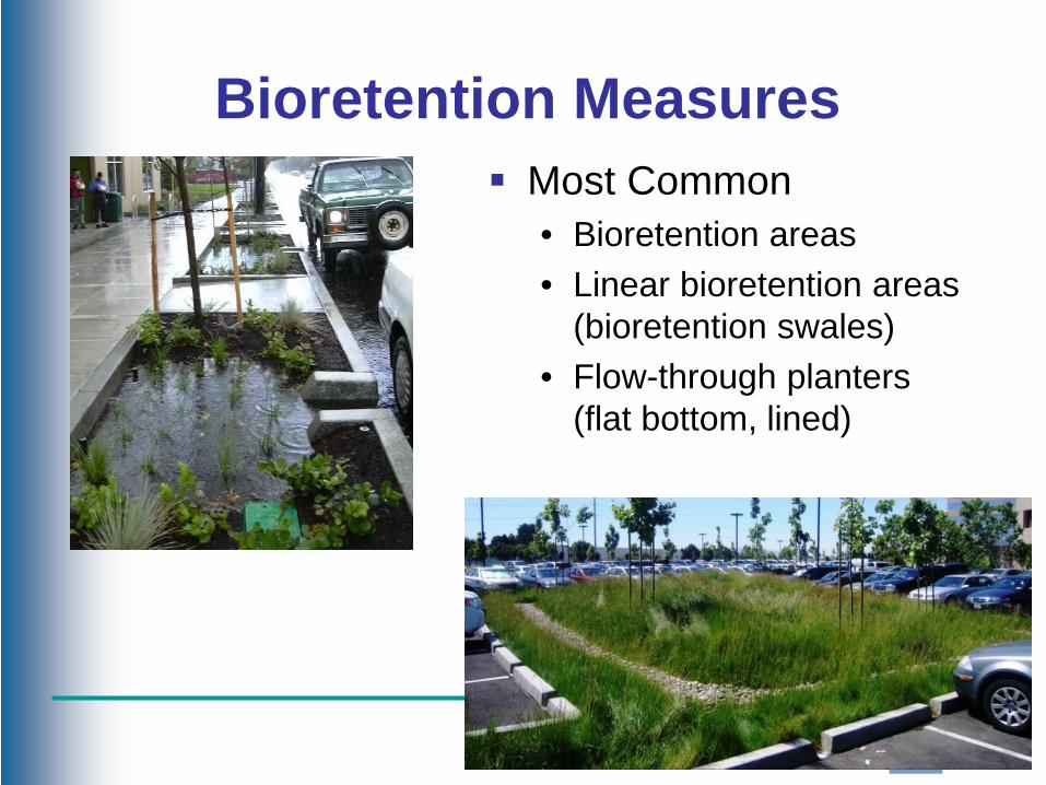
Bioretention Measures Most Common
• Bioretention areas• Linear bioretention areas
(bioretention swales)• Flow-through planters
(flat bottom, lined)
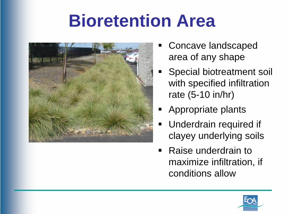
Bioretention Area Concave landscaped
area of any shape Special biotreatment soil
with specified infiltration rate (5-10 in/hr)
Appropriate plants Underdrain required if
clayey underlying soils Raise underdrain to
maximize infiltration, if conditions allow
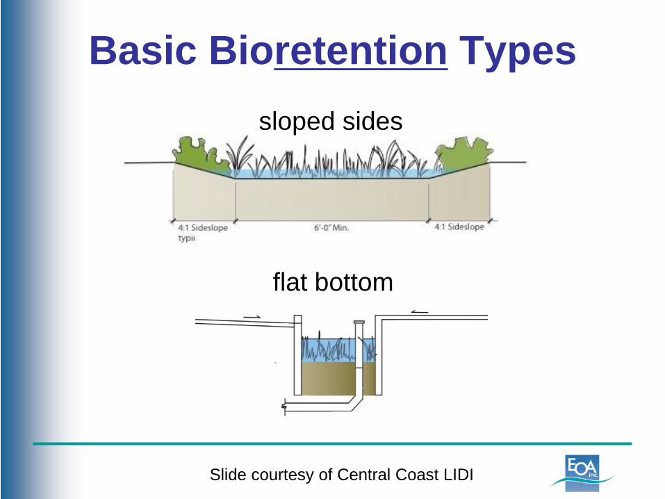
Basic Bioretention Typessloped sides
flat bottom
Slide courtesy of Central Coast LIDI
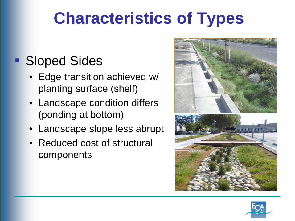
Sloped Sides • Edge transition achieved w/
planting surface (shelf)• Landscape condition differs
(ponding at bottom)• Landscape slope less abrupt• Reduced cost of structural
components
Characteristics of Types
Hig
h Po
int C
omm
unity
, Sv
R D
esig
n
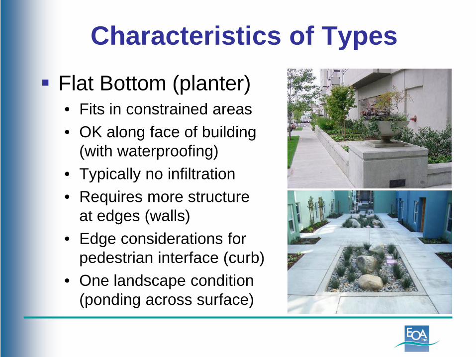
Flat Bottom (planter)• Fits in constrained areas• OK along face of building
(with waterproofing)• Typically no infiltration• Requires more structure
at edges (walls)• Edge considerations for
pedestrian interface (curb)• One landscape condition
(ponding across surface)
Characteristics of Types
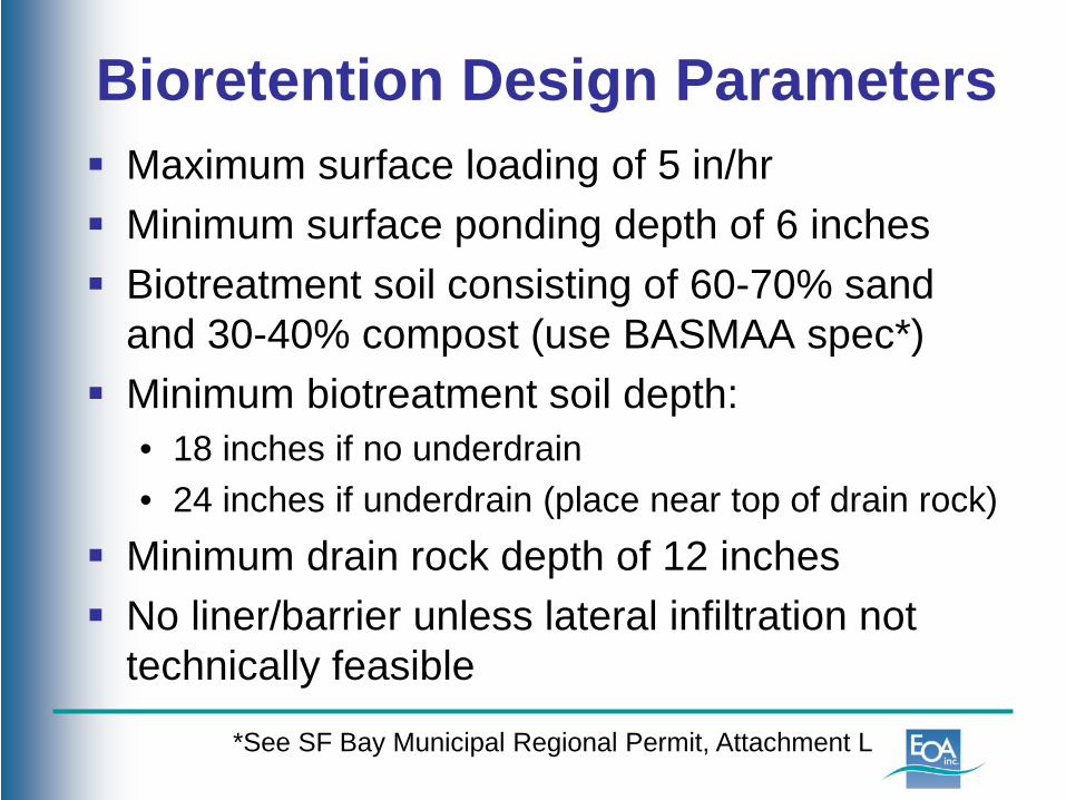
Maximum surface loading of 5 in/hr Minimum surface ponding depth of 6 inches Biotreatment soil consisting of 60-70% sand
and 30-40% compost (use BASMAA spec*) Minimum biotreatment soil depth:
• 18 inches if no underdrain• 24 inches if underdrain (place near top of drain rock)
Minimum drain rock depth of 12 inches No liner/barrier unless lateral infiltration not
technically feasible
Bioretention Design Parameters
*See SF Bay Municipal Regional Permit, Attachment L
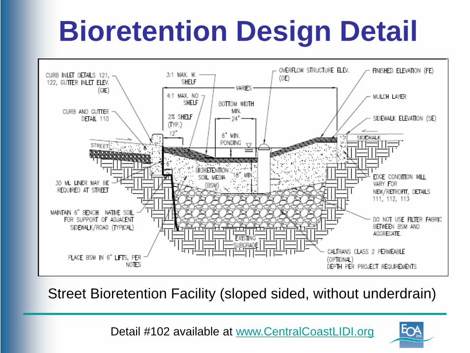
Bioretention Design Detail
Street Bioretention Facility (sloped sided, without underdrain)
Detail #102 available at www.CentralCoastLIDI.org
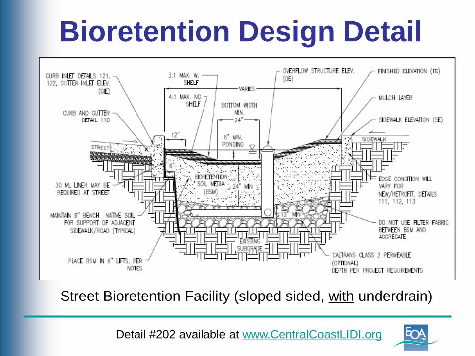
Bioretention Design Detail
Street Bioretention Facility (sloped sided, with underdrain)
Detail #202 available at www.CentralCoastLIDI.org
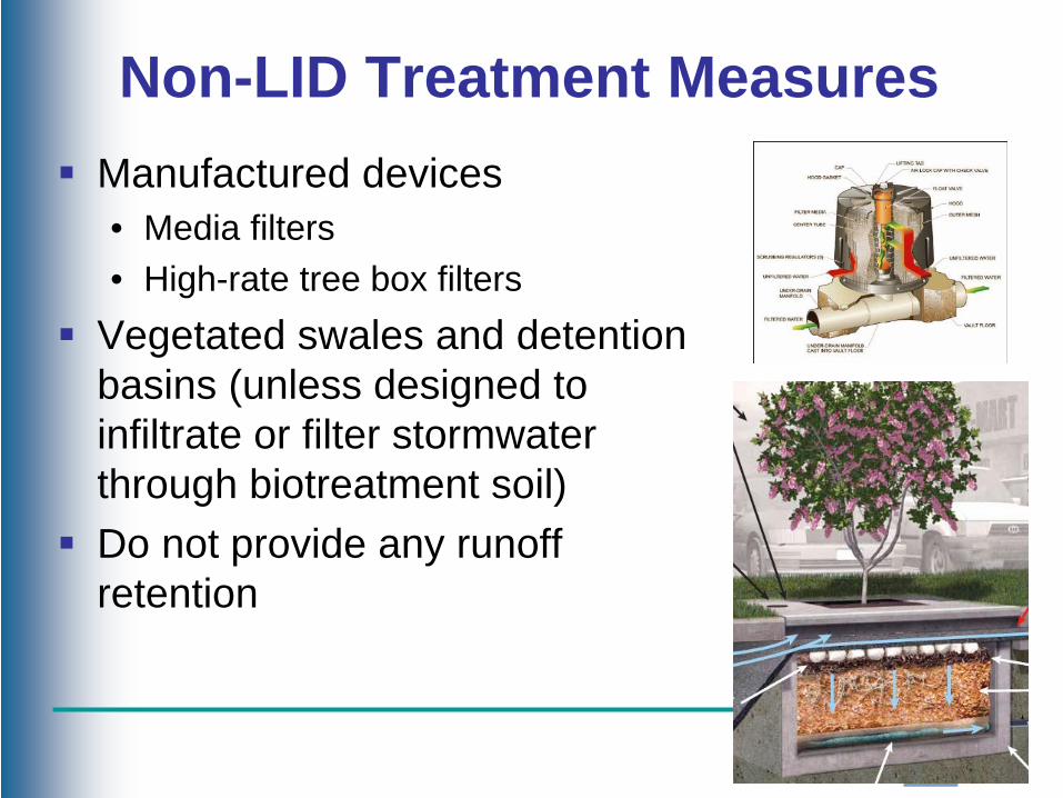
Non-LID Treatment Measures Manufactured devices
• Media filters• High-rate tree box filters
Vegetated swales and detentionbasins (unless designed to infiltrate or filter stormwaterthrough biotreatment soil)
Do not provide any runoffretention
Non-LID Treatment Measures PCRs state that Non-Retention Based
Treatment is the least preferred option but no specific conditions for use
Phase II permit (and Santa Barbara TechnicalGuide) allows use only when:• Projects that create/replace ≤ 1 acre impervious
surface in pedestrian oriented commercial districtwith 85% lot coverage by permanent structures
• Facilities receiving runoff solely from existing (pre-project) impervious areas
• Historic sites that cannot alter original configuration
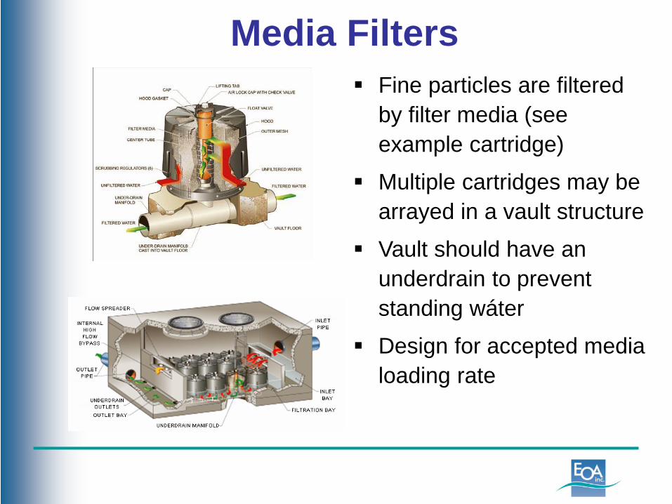
Media Filters Fine particles are filtered
by filter media (see example cartridge)
Multiple cartridges may be arrayed in a vault structure
Vault should have an underdrain to prevent standing wáter
Design for accepted media loading rate

Manufactured Tree Well Filters
Example of a Manufactured Tree Well Filter
Tree well filter with proprietary planting media and underdrain
Planting media has extremely high infiltration rate.
Now available with biotreatment soil to meet LID requirements (but treats smaller area).
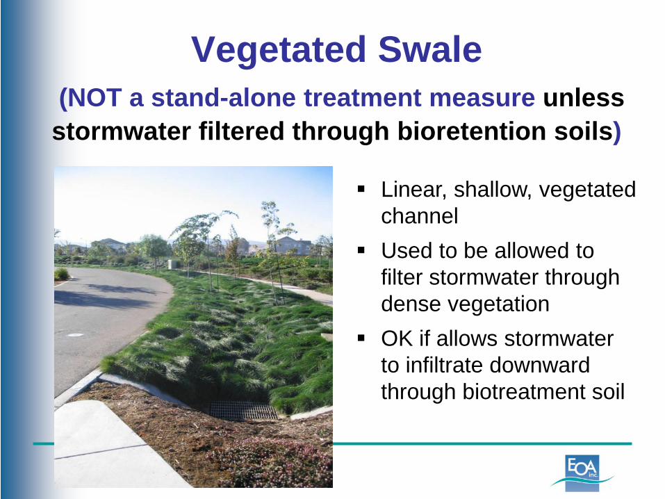
Vegetated Swale(NOT a stand-alone treatment measure unless stormwater filtered through bioretention soils)
Linear, shallow, vegetated channel
Used to be allowed to filter stormwater through dense vegetation
OK if allows stormwater to infiltrate downward through biotreatment soil
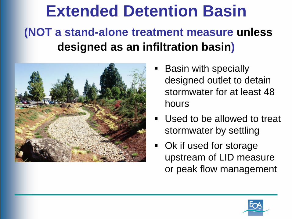
Extended Detention Basin(NOT a stand-alone treatment measure unless
designed as an infiltration basin)
Basin with specially designed outlet to detain stormwater for at least 48 hours
Used to be allowed to treat stormwater by settling
Ok if used for storage upstream of LID measure or peak flow management

Runoff Retention Requirements Site Assessment
• Review/document opportunities & constraints Site Design Measures Runoff Reduction Measures
• Self-treating and self-retaining areas Structural Stormwater Control Measures
• Retain remaining runoff
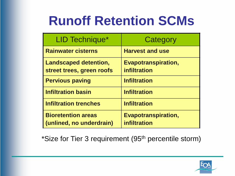
Runoff Retention SCMsLID Technique* Category
Rainwater cisterns Harvest and use
Landscaped detention, street trees, green roofs
Evapotranspiration, infiltration
Pervious paving Infiltration
Infiltration basin Infiltration
Infiltration trenches Infiltration
Bioretention areas (unlined, no underdrain)
Evapotranspiration, infiltration
*Size for Tier 3 requirement (95th percentile storm)
Runoff Retention SCMs Can combine with LID treatment facilities Will typically need to provide additional storage
to retain more runoff from 95th percentile storm• Larger surface area of facility• More storage below facility (e.g., deeper drain rock
layer or subsurface infiltration structures)• Increased surface storage in basin
If can’t meet on-site (after 10% adjustment):• Reduce impervious surface on site• Consider mitigation off-site
Peak Management Options Additional storage may be needed to match 2-
10-year pre-project peak flows, depending on: • Pre-project imperviousness• Site soil type• Amount of runoff retention
Study being conducted to determine under what conditions meeting Tier 3 also meets Tier 4
Can combine 2- to 10-year peak control with required flood control facilities
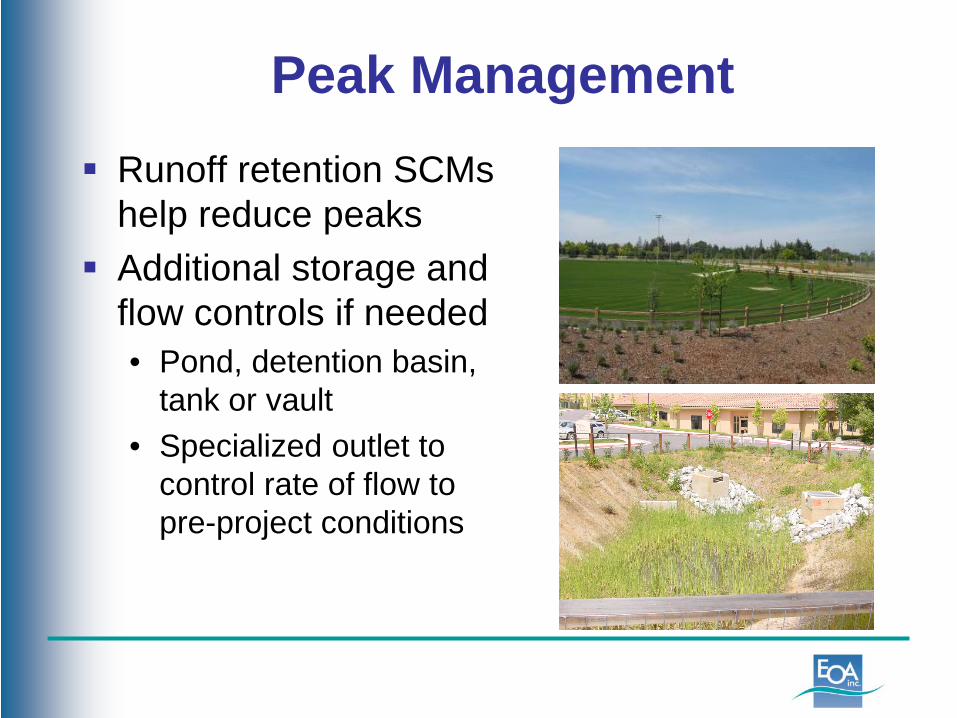
Peak Management Runoff retention SCMs
help reduce peaks Additional storage and
flow controls if needed• Pond, detention basin,
tank or vault• Specialized outlet to
control rate of flow topre-project conditions
Source Control Measures Phase II permit requires Regulated Projects with
pollutant generating activities and sources to implement source control measures as applicable.
Examples of pollutant sources include:• Pools, spas, and fountains• Restaurant operations• Vehicle and equipment cleaning areas• Outdoor storage of equipment, materials or wastes• Non-stormwater discharges • Pesticide/fertilizer use on landscaping
Applicants should document pollutant sources and control measures in Stormwater Control Plan
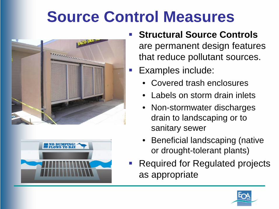
Source Control Measures Structural Source Controls
are permanent design features that reduce pollutant sources.
Examples include:• Covered trash enclosures• Labels on storm drain inlets• Non-stormwater discharges
drain to landscaping or to sanitary sewer
• Beneficial landscaping (native or drought-tolerant plants)
Required for Regulated projects as appropriate
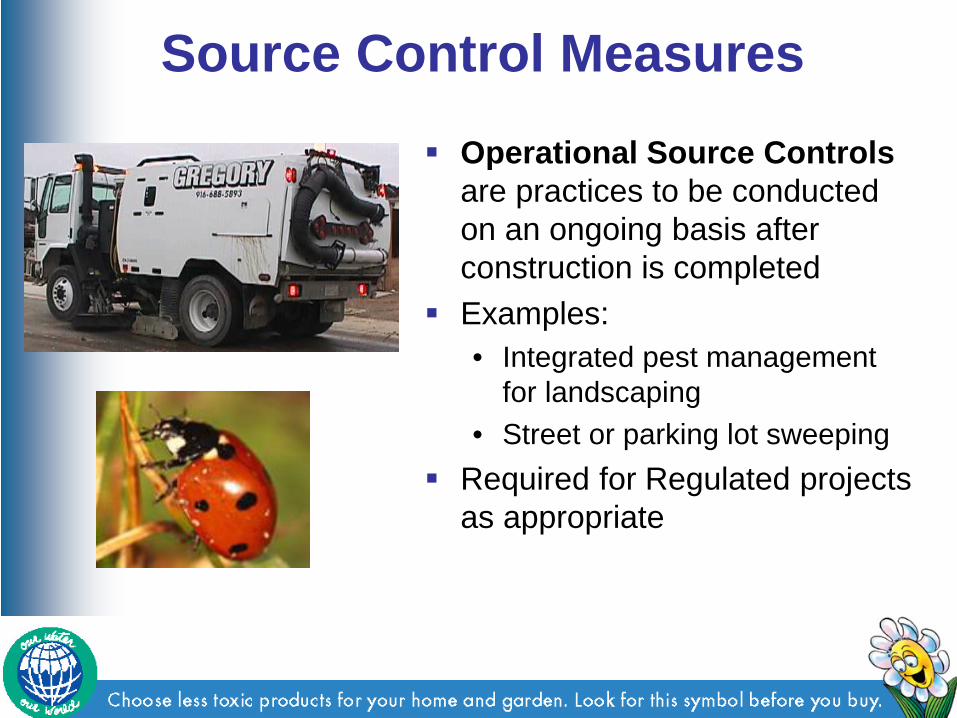
Source Control Measures Operational Source Controls
are practices to be conducted on an ongoing basis after construction is completed
Examples: • Integrated pest management
for landscaping• Street or parking lot sweeping
Required for Regulated projects as appropriate