Embed Size (px)
Citation preview
MONO PUMPS LIMITED
Mechanical Joint Replacement Kit
SECTION N-1 Pre-Selection Table
SECTION N-2 Coding
SECTION N-3 Rotating Parts Code
SECTION N-4 Materials of Construction
SECTION N-5 General Arrangements
SECTION N-6 Bearings
SECTION N-7 Gland Section Dimensions
SECTION N-8 Packing / Seal Details
SECTION N-9 Rotor Dimensions
SECTION N-10 Stator Dimensions
SECTION N-11 Selection Procedure
SECTION N-12 Performance Curves
PUMP RANGE MJRK SECTION N-1
MODEL ALL PAGE 1
STATUS CURRENT
MONO PUMPS LIMITED
DATE Jan 1999
Published information other than that marked certified is to be used as a guide only
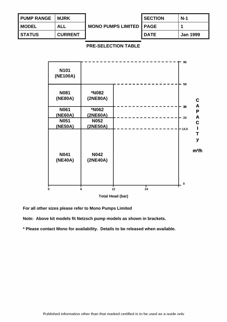
PRE-SELECTION TABLE
N101(NE100A)
N081(NE80A)
*N082(2NE80A)
N061(NE60A)
*N062(2NE60A)
N051(NE50A)
N052(2NE50A)
N041(NE40A)
N042(2NE40A)
0 6 12 24
58
96
Total Head (bar)
For all other sizes please refer to Mono Pumps Limited
Note: Above kit models fit Netzsch pump models as shown in brackets.
* Please contact Mono for availability. Details to be released when available.
0
14.5
24
35
CAPACITy
m³/h
35
CAPACITy
m³/h
PUMP RANGE MJRK SECTION N-2
MODEL ALL PAGE 1
STATUS CURRENT
MONO PUMPS LIMITED
DATE Jan 1999
Published information other than that marked certified is to be used as a guide only
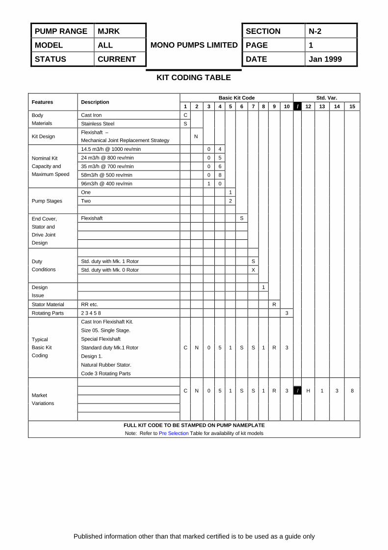
KIT CODING TABLE
Basic Kit Code Std. Var.Features Description
1 2 3 4 5 6 7 8 9 10 / 12 13 14 15
Cast Iron CBody
Materials Stainless Steel S
Kit DesignFlexishaft –
Mechanical Joint Replacement StrategyN
14.5 m3/h @ 1000 rev/min 0 4
24 m3/h @ 800 rev/min 0 5
35 m3/h @ 700 rev/min 0 6
58m3/h @ 500 rev/min 0 8
Nominal Kit
Capacity and
Maximum Speed
96m3/h @ 400 rev/min 1 0
One 1
Two 2Pump Stages
Flexishaft SEnd Cover,
Stator and
Drive Joint
Design
Std. duty with Mk. 1 Rotor S
Std. duty with Mk. 0 Rotor X
Duty
Conditions
1Design
Issue
Stator Material RR etc. R
Rotating Parts 2 3 4 5 8 3
Cast Iron Flexishaft Kit.
Size 05. Single Stage.
Special Flexishaft
Standard duty Mk.1 Rotor
Design 1.
Natural Rubber Stator.
Typical
Basic Kit
Coding
Code 3 Rotating Parts
C N 0 5 1 S S 1 R 3
C N 0 5 1 S S 1 R 3 / H 1 3 8Market
Variations
FULL KIT CODE TO BE STAMPED ON PUMP NAMEPLATE
Note: Refer to Pre Selection Table for availability of kit models
PUMP RANGE MJRK SECTION N-3
MODEL ALL PAGE 1
STATUS CURRENT
MONO PUMPS LIMITED
DATE Jan 1999
Published information other than that marked certified is to be used as a guide only
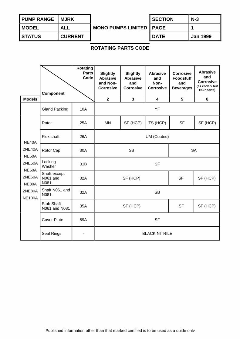
ROTATING PARTS CODE
Component
RotatingPartsCode
SlightlyAbrasiveand Non-Corrosive
SlightlyAbrasive
andCorrosive
AbrasiveandNon-
Corrosive
CorrosiveFoodstuff
andBeverages
Abrasiveand
Corrosive(as code 5 but
HCP parts)
Models 2 3 4 5 8
Gland Packing 10A YF
Rotor 25A MN SF (HCP) TS (HCP) SF SF (HCP)
Flexishaft 26A UM (Coated)
Rotor Cap 30A SB SA
LockingWasher 31B SF
Shaft exceptN061 andN081.
32A SF (HCP) SF SF (HCP)
Shaft N061 andN081. 32A SB
Stub ShaftN061 and N081 35A SF (HCP) SF SF (HCP)
Cover Plate 59A SF
NE40A
2NE40A
NE50A
2NE50A
NE60A
2NE60A
NE80A
2NE80A
NE100A
Seal Rings - BLACK NITRILE
PUMP RANGE MJRK SECTION N-4
MODEL ALL PAGE 1
STATUS CURRENT
MONO PUMPS LIMITED
DATE Jan 1999
Published information other than that marked certified is to be used as a guide only
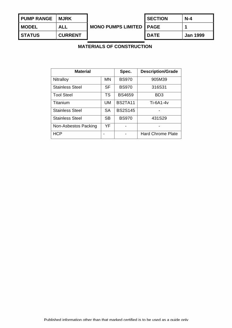
MATERIALS OF CONSTRUCTION
Material Spec. Description/Grade
Nitralloy MN BS970 905M39
Stainless Steel SF BS970 316S31
Tool Steel TS BS4659 BD3
Titanium UM BS2TA11 Ti-6A1-4v
Stainless Steel SA BS2S145 -
Stainless Steel SB BS970 431S29
Non-Asbestos Packing YF - -
HCP - - Hard Chrome Plate
PUMP RANGE MJRK SECTION N-5
MODEL ALL PAGE 1
STATUS CURRENT
MONO PUMPS LIMITED
DATE Jan 1999
Published information other than that marked certified is to be used as a guide only
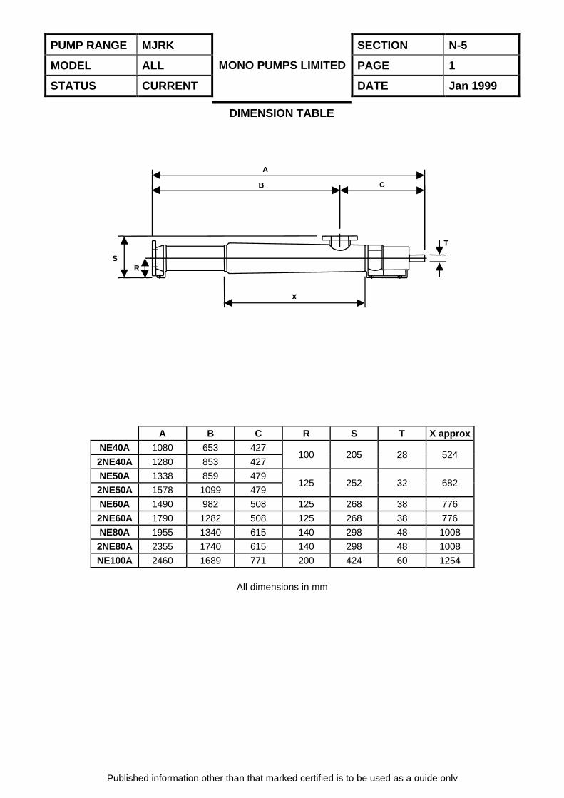
DIMENSION TABLE
A B C R S T X approxNE40A 1080 653 427
2NE40A 1280 853 427100 205 28 524
NE50A 1338 859 479
2NE50A 1578 1099 479125 252 32 682
NE60A 1490 982 508 125 268 38 776
2NE60A 1790 1282 508 125 268 38 776
NE80A 1955 1340 615 140 298 48 1008
2NE80A 2355 1740 615 140 298 48 1008
NE100A 2460 1689 771 200 424 60 1254
All dimensions in mm
A
B C
X
SR
T
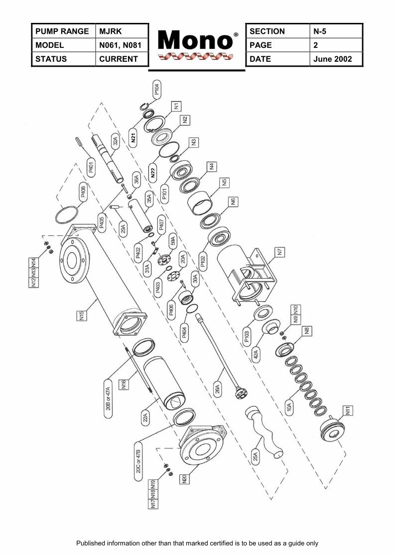
PUMP RANGE MJRK SECTION N-5MODEL N061, N081 PAGE 2STATUS CURRENT DATE June 2002
Published information other than that marked certified is to be used as a guide only
N06
1, N
081
N21
N22
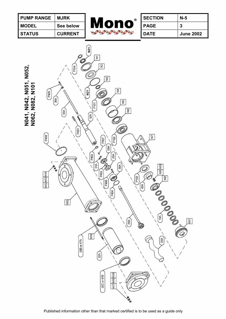
PUMP RANGE MJRK SECTION N-5MODEL See below PAGE 3STATUS CURRENT DATE June 2002
Published information other than that marked certified is to be used as a guide only
N04
1, N
042,
N05
1, N
052,
N06
2, N
082,
N10
1
N21
N21
PUMP RANGE MJRK SECTION N-5MODEL ALL PAGE 4STATUS CURRENT DATE June 2002
Published information other than that marked certified is to be used as a guide only
DRAWING REFERENCE NUMBERS
Kit Components Existing ComponentsDrg. Ref. Description Drg. Ref. Description
10A Gland Packing N1 Circlip20A Gasket – Adaptor N2 Bearing Cover20B Gasket – Stator N3 Washer20C Gasket – Stator N4 Seal Ring22A Stator N5 Bearing Spacer25A Rotor N6 Seal Ring26A Flexishaft N7 Body29A Shaft Pin N8 Gland Follower30A Rotor Cap N9 Nut31A Locking Washer N10 Plain Washer32A Shaft N11 Gland Section35A Stub Shaft N12 Nut36A Locking Collar N13 Spring Washer42A Thrower N14 Plain Washer47A Stator Support Ring N15 Suction Chamber47B Stator Support Ring N16 Tie Bar59A Cover Plate N17 Nut95A Tie Rod N18 Spring Washer
P101 Deep Groove Ball Bearing N19 Plain WasherP102 Deep Groove Ball Bearing N20 End CoverP103 Lipseal N21 LipsealP104 Circlip N22 ‘O’ RingP401 Rectangular KeyP402 Seal RingP403 Seal RingP404 Seal RingP405 Socket Headed Cap ScrewP406 Socket Headed Cap ScrewP407 Hex. Hd. BoltP408 Toroidal Seal Ring
PUMP RANGE MJRK SECTION N-6
MODEL ALL PAGE 1
STATUS CURRENT
MONO PUMPS LIMITED
DATE Jan 1999
Published information other than that marked certified is to be used as a guide only
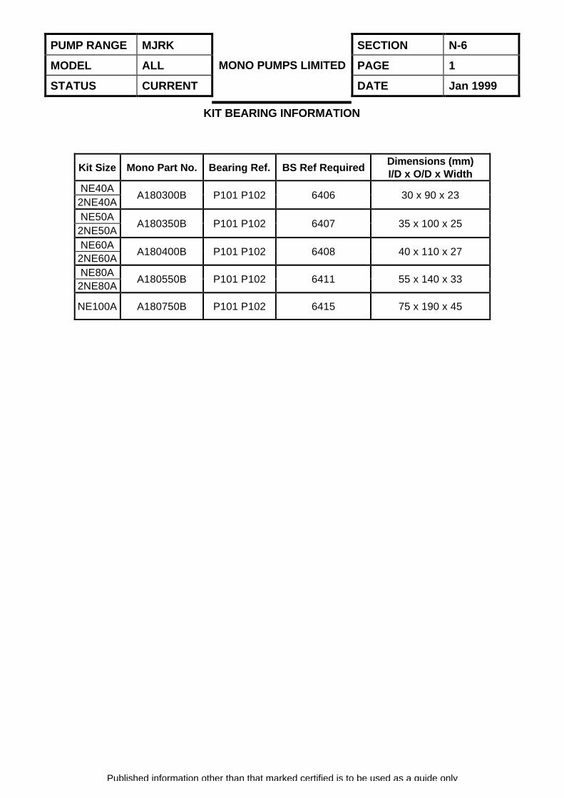
KIT BEARING INFORMATION
Kit Size Mono Part No. Bearing Ref. BS Ref RequiredDimensions (mm)I/D x O/D x Width
NE40A2NE40A
A180300B P101 P102 6406 30 x 90 x 23
NE50A2NE50A
A180350B P101 P102 6407 35 x 100 x 25
NE60A2NE60A
A180400B P101 P102 6408 40 x 110 x 27
NE80A2NE80A
A180550B P101 P102 6411 55 x 140 x 33
NE100A A180750B P101 P102 6415 75 x 190 x 45
PUMP RANGE MJRK SECTION N-7
MODEL ALL PAGE 1
STATUS CURRENT
MONO PUMPS LIMITED
DATE June 1999
Published information other than that marked certified is to be used as a guide only
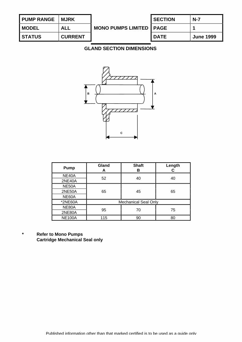
GLAND SECTION DIMENSIONS
PumpGland
AShaft
BLength
CNE40A2NE40A
52 40 40
NE50A2NE50ANE60A
65 45 65
*2NE60A Mechanical Seal OnlyNE80A2NE80A
95 70 75
NE100A 115 90 80
* Refer to Mono PumpsCartridge Mechanical Seal only
C
B A
PUMP RANGE MJRK SECTION N-8
MODEL ALL PAGE 1
STATUS CURRENT
MONO PUMPS LIMITED
DATE June 1999
Published information other than that marked certified is to be used as a guide only
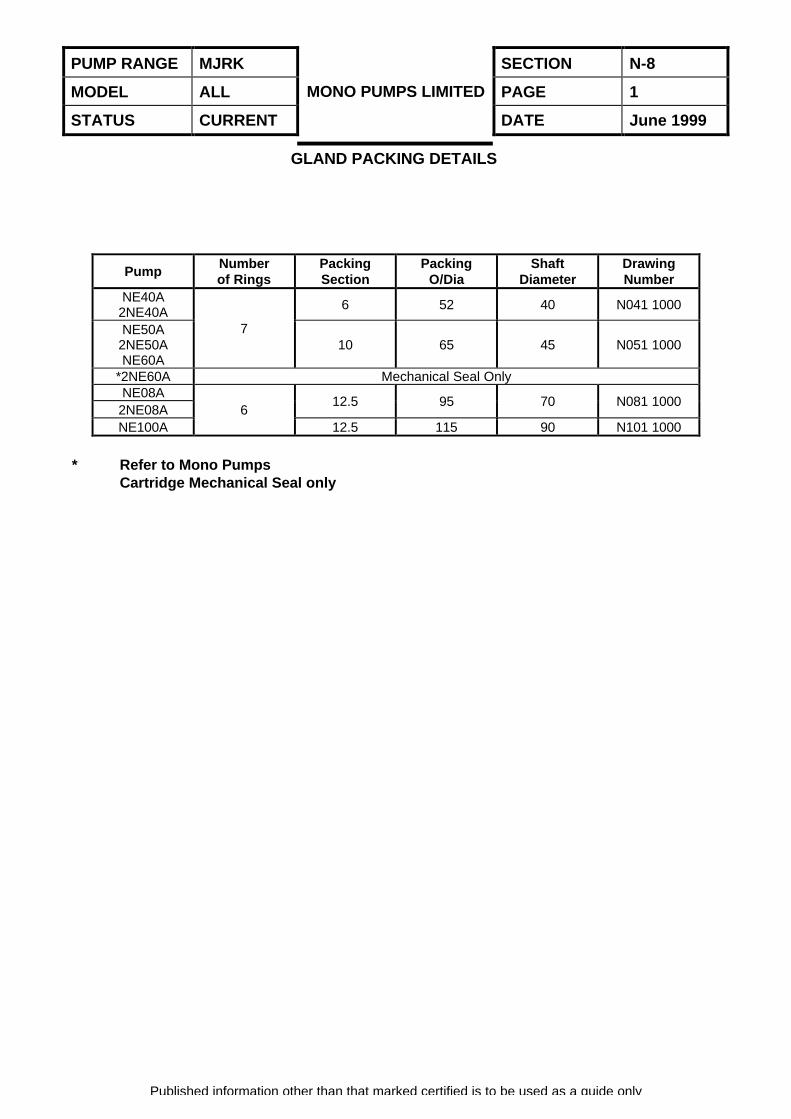
GLAND PACKING DETAILS
PumpNumberof Rings
PackingSection
PackingO/Dia
ShaftDiameter
DrawingNumber
NE40A2NE40A 6 52 40 N041 1000
NE50A2NE50ANE60A
710 65 45 N051 1000
*2NE60A Mechanical Seal OnlyNE08A
2NE08A12.5 95 70 N081 1000
NE100A6
12.5 115 90 N101 1000
* Refer to Mono PumpsCartridge Mechanical Seal only
PUMP RANGE MJRK SECTION N-9
MODEL ALL PAGE 1
STATUS CURRENT
MONO PUMPS LIMITED
DATE Jan 1999
Published information other than that marked certified is to be used as a guide only
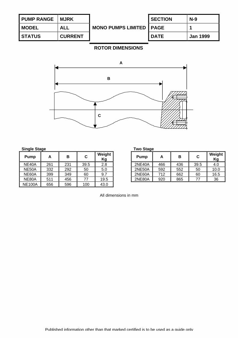
ROTOR DIMENSIONS
Single Stage Two Stage
Pump A B CWeight
KgPump A B C
WeightKg
NE40A 261 231 39.5 2.8 2NE40A 466 436 39.5 4.0NE50A 332 292 50 5.0 2NE50A 592 552 50 10.0NE60A 399 349 60 9.7 2NE60A 712 662 60 16.5NE80A 511 456 77 19.5 2NE80A 920 865 77 36NE100A 656 596 100 43.0
All dimensions in mm
C
B
A
PUMP RANGE MJRK SECTION N-10
MODEL ALL PAGE 1
STATUS CURRENT
MONO PUMPS LIMITED
DATE Jan 1999
Published information other than that marked certified is to be used as a guide only
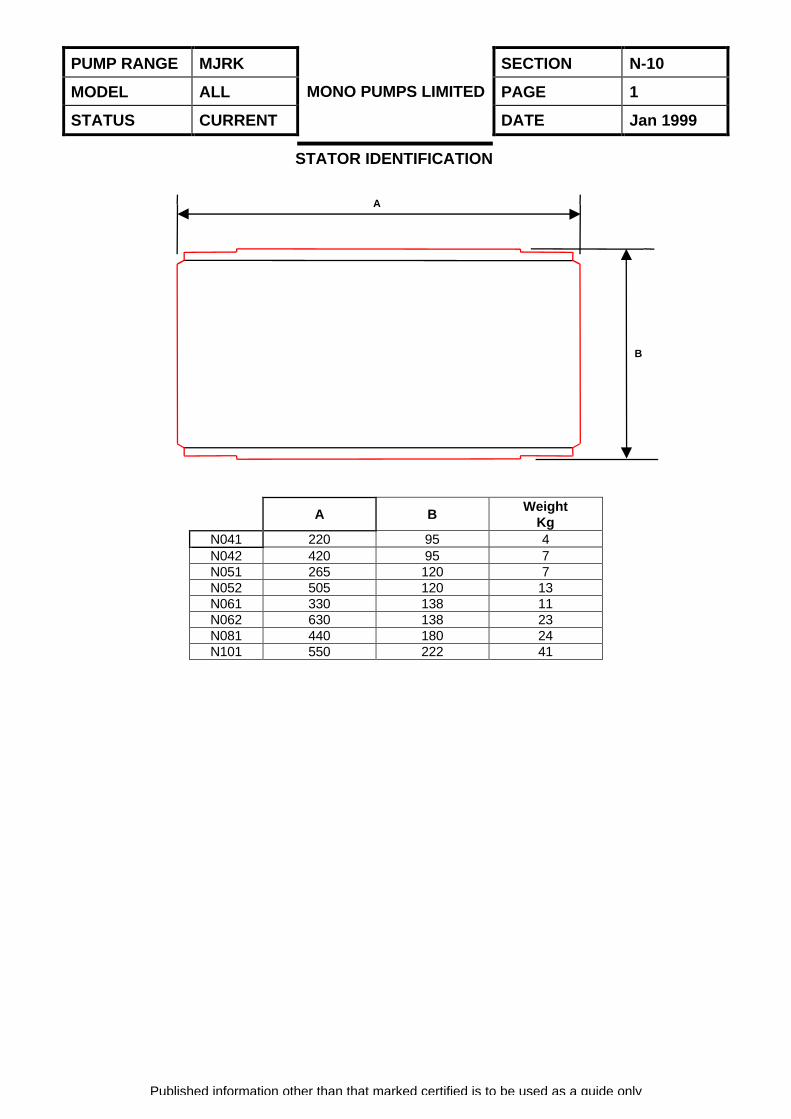
STATOR IDENTIFICATION
A BWeight
KgN041 220 95 4N042 420 95 7N051 265 120 7N052 505 120 13N061 330 138 11N062 630 138 23N081 440 180 24N101 550 222 41
A
B
PUMP RANGE MJRK SECTION N-11
MODEL ALL PAGE 1
STATUS CURRENT
MONO PUMPS LIMITED
DATE Jan 1999
SELECTION PROCEDURE
Published information other than that marked certified is to be used as a guide only
INTRODUCTION
Although the kit selection is expected to be similarto the existing Netzsch equivalent, it isrecommended the following procedure be followedto check the suitability to the application and drivearrangement.
PUMP SIZING
1. From the pre-selection table (Section N-1)select the pump model which initially meets therequired capacity/pressure criteria. (Refer toNOTES, page 4).
2. If particle size is a factor then refer to the tablelabelled ‘SOLIDS HANDLING’ (mm) on theperformance graph to verify the pumpssuitability.
3. If variable speed is required then select atmaximum capacity.
4. On the y-axis (Capacity) identify the requiredflow then move horizontally until intersection atthe required differential pressure (see page 5).
5. Slip Correction for Viscosity
(a) If Viscosity is equal to or greater than six (6)stokes then select on the zero bar pressure lineto determine the pump speed required for theduty. From the point of intersection on thecurve move vertically down to the x-axislabelled ‘Speed’ to obtain the required RPM.
(b) If the Viscosity is less than six (6) stokes thenthe following procedure applies:-
Use the method given here as Figs. 1 and 2 toestimate ‘Slip’ and calculate the required pumpspeed.
Slip Correction for Viscosityn = np – [ (np – no) f ]
or n = np – f.ns
wheren = corrected duty speedno = rpm at zero bar for duty flow rate(from water performance curves)np = rpm at duty pressure for duty flowrate (from water performance curves (Fig1))np-no = Slip speed = ns
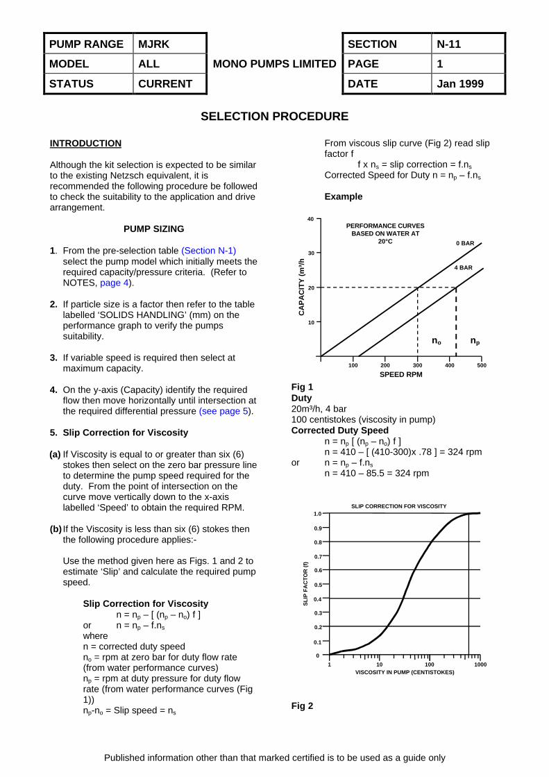
From viscous slip curve (Fig 2) read slipfactor f
f x ns = slip correction = f.ns
Corrected Speed for Duty n = np – f.ns
Example
Fig 1Duty20m³/h, 4 bar100 centistokes (viscosity in pump)Corrected Duty Speed
n = np [ (np – no) f ]n = 410 – [ (410-300)x .78 ] = 324 rpm
or n = np – f.ns
n = 410 – 85.5 = 324 rpm
Fig 2
100 200 300 400 500
40
30
20
10
SPEED RPM
CA
PA
CIT
Y (
m³/
h
PERFORMANCE CURVESBASED ON WATER AT
20°C
no np
0 BAR
4 BAR
VISCOSITY IN PUMP (CENTISTOKES)
SLIP CORRECTION FOR VISCOSITY
SL
IP F
AC
TO
R (
f)
1 10 100 1000
0
0.1
0.2
0.3
0.4
0.5
0.6
0.7
0.8
0.9
1.0
PUMP RANGE MJRK SECTION N-11
MODEL ALL PAGE 2
STATUS CURRENT
MONO PUMPS LIMITED
DATE Jan 1999
SELECTION PROCEDURE
Published information other than that marked certified is to be used as a guide only
Note: There is no slip correction necessary forwater or product with a viscosity of one (1)centistoke.
6. When RPM is established identify:
(a) Maximum viscosity as indicated at the top ofthe performance curve labelled ‘ViscosityLimits’. Refer to page 3, Tolerance guidelines– Viscosity Limits.
(b)Abrasion capability as indicated at the top ofthe performance curve labelled ‘AbrasionZone’. Refer to page 3, Tolerance guidelines– Abrasion Zone.
If any of the parameters in steps 1 to 6 (b) donot meet the required criteria then re-selectfrom (1) above with the next larger pump size.
(c) Rotor selection against temperature asindicated in the shaded area of theperformance curve for the duty speedidentified.
Refer to Tolerance Guidelines – RotorSelection.
(d)Absorbed power which is read on the y-axis(Absorbed power) at the differential pressureintersection point (BHP).
If the product is viscous then note also theabsorbed power on the zero pressure line(FHP) for use later in calculation.
7. If the pump meets the above criteria go to thePUMP CONFIRMATION SECTION. If nopump can be identified then please contactMono Pumps Ltd for assistance.
PUMP CONFIRMATION
Having determined the pump size the followingsteps are necessary:
1. Read the NPSH required from the pump curveat the duty flowrate.
Check that the NPSH required is less thanNPSH available.
2. Note the starting torque required on theperformance curve in the table labelled
‘STARTING TORQUE’ against the selectedrotor.
3. If the product is viscous obtain both StartingTorque (f T) and Power Additive (f FHP)factors from the Viscosity Curve graph read atthe known viscosity in Stokes.
4. Confirm stator suitability for the product.(Refer to page 3, Tolerance Guidelines –Stator Selection).
5. Confirm material compatibility and availabilityfor the pump chosen.
6. Confirm availability of packed gland ormechanical seal for the pump chosen.
DRIVE
Information obtained from the PUMPCONFIRMATION section will be used todetermine the required drive.
1. If product is water like, then the absorbedpower (BHP) will be as obtained in the PUMPSIZING section, step 6, item (d). Got to step 4.
2. Multiplying the pump starting torque by thestarting torque factor obtained in the PUMPCONFIRMATION section, item 3 will give youthe starting torque required for the givenviscosity.
(i.e. T(N.M.) x ft = Starting torque at viscosity).(Refer to section DRIVE, item 5 and 6).
3. To obtain the power absorbed at the knowviscosity then the full viscous calculation is:
Viscous Brake Horsepower (V BHP) = Viscousfrictional H.P. + W.H.P.
(a) Viscous Frictional Horsepower FHP x fFHP. FHP as identified in Pump Sizingsection step 6, item (d) (zero bar pressure).F FHP factor as identified in PumpConfirmation section step 3.
Multiply FHP by correction factor f FHP togive frictional horsepower when handlingthe viscous product.
(b) Water Horsepower (WHP) is BHP – FHP
PUMP RANGE MJRK SECTION N-11
MODEL ALL PAGE 3
STATUS CURRENT
MONO PUMPS LIMITED
DATE Jan 1999
SELECTION PROCEDURE
Published information other than that marked certified is to be used as a guide only
BHP as identified in Pump Sizing sectionstep 6, item (d) (at duty pressure)FHP as identified in Pump Sizing sectionstep 6, item (d) (at zero bar pressure).WHP is BHP – FHP.
(c) Add viscous frictional horsepower to waterhorsepower to obtain BHP absorbed whenhandling a viscous product i.e. a + b.
4. Determine the motor input power required byallowing for the efficiency of the drivearrangement as follows:
Standard PumpsDrive Arrangement Efficiency
%D.C. to a synchronous speed motor 100D.C. to a fixed speed geared motor 92D.C. to a variable speed geared motor 80Vee drive 97
(D.C. = Direct Coupled)
Therefore input power = BHP (or vBHP)divided by the efficiency.
(i.e. Input power required for a close coupledCB pump with a direct coupled fixed speedgeared motor = BHP (or vBHP) / 0.92)
5. Starting torque capabilities will be affected bythe type of drive selected and method ofstarting.
Generally motors wired for D.O.L. start on a 3phase supply will provide 200% FLT (Full LoadTorque).
Motors wired for Star/Delta start on a 3 phasesupply typically provide 100% FLT.
Single-phase motors (capacitor start) typicallyprovide 200% FLT.
In all cases reference should be made to themotor manufacturers performance tables.
D.O.L. is the preferred method of starting aPC pump.
6. If starting is via an inverter type of drive then100% FLT availability only is assumed. Thecorrect matching of drive motor/inverter/pump
is a specialised skill. Breakout torque andcontinuous slow running can cause problems.
Always refer an inverter application to aspecialist dive company, ensuring that they areaware of the full duty parameters to enablethem to select the appropriate drive package.
7. Care should be taken when selecting othertypes of drives to ensure sufficient startingtorque is available, i.e. single phase, hydraulicdrives, air motors, engines etc. If in doubtrefer to Mono Pumps Ltd.
TOLERANCE GUIDELINES
Rotor Selection
Consider maximum fluid temperature, ambienttemperature, operating speed and duration ofrunning. All these factors affect statortemperature, in borderline cases select the highertemperature rotor.
Fixed Speed
If selection falls exactly between rotor types thenselect the higher temperature rotor.
Variable Speed
For variable speed drives select the rotor atmaximum speed and maximum temperature.
Mark 0 Rotors
Mk 0 rotors are only designed for use with waterlike liquids, i.e. less than 200 centistokes andwhere either of the following details apply:
i) Pressure per Stage is greater than two (2) bar.orii) Suction required is greater then three (3)
metres H20.
Refer to performance curves for further details.Stator Selection
Performance curves based on RR and RA statormaterials. RR, RA, RH and RV are Mono statormaterial codes and are contained in the statorselection for each model.
PUMP RANGE MJRK SECTION N-11
MODEL ALL PAGE 4
STATUS CURRENT
MONO PUMPS LIMITED
DATE Jan 1999
SELECTION PROCEDURE
Published information other than that marked certified is to be used as a guide only
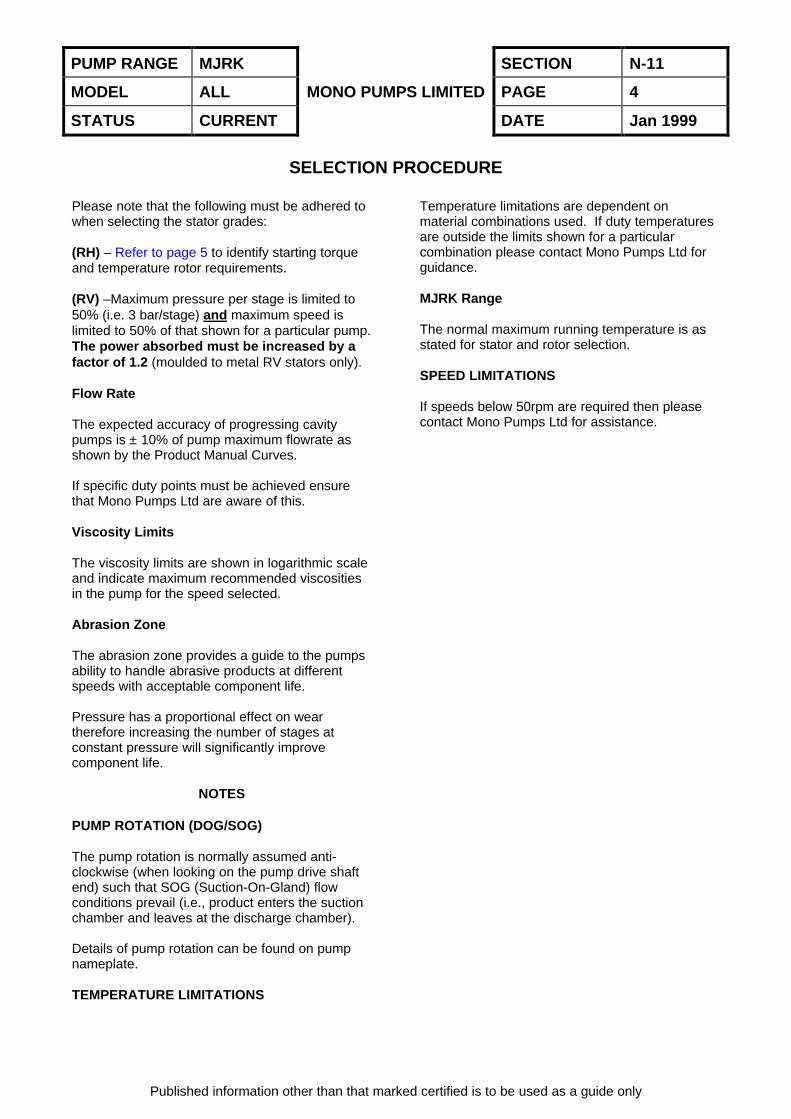
Please note that the following must be adhered towhen selecting the stator grades:
(RH) – Refer to page 5 to identify starting torqueand temperature rotor requirements.
(RV) –Maximum pressure per stage is limited to50% (i.e. 3 bar/stage) and maximum speed islimited to 50% of that shown for a particular pump.The power absorbed must be increased by afactor of 1.2 (moulded to metal RV stators only).
Flow Rate
The expected accuracy of progressing cavitypumps is ± 10% of pump maximum flowrate asshown by the Product Manual Curves.
If specific duty points must be achieved ensurethat Mono Pumps Ltd are aware of this.
Viscosity Limits
The viscosity limits are shown in logarithmic scaleand indicate maximum recommended viscositiesin the pump for the speed selected.
Abrasion Zone
The abrasion zone provides a guide to the pumpsability to handle abrasive products at differentspeeds with acceptable component life.
Pressure has a proportional effect on weartherefore increasing the number of stages atconstant pressure will significantly improvecomponent life.
NOTES
PUMP ROTATION (DOG/SOG)
The pump rotation is normally assumed anti-clockwise (when looking on the pump drive shaftend) such that SOG (Suction-On-Gland) flowconditions prevail (i.e., product enters the suctionchamber and leaves at the discharge chamber).
Details of pump rotation can be found on pumpnameplate.
TEMPERATURE LIMITATIONS
Temperature limitations are dependent onmaterial combinations used. If duty temperaturesare outside the limits shown for a particularcombination please contact Mono Pumps Ltd forguidance.
MJRK Range
The normal maximum running temperature is asstated for stator and rotor selection.
SPEED LIMITATIONS
If speeds below 50rpm are required then pleasecontact Mono Pumps Ltd for assistance.
PUMP RANGE MJRK SECTION N-11
MODEL ALL PAGE 5
STATUS CURRENT
MONO PUMPS LIMITED
DATE Jan 1999
Published information other than that marked certified is to be used as a guide only
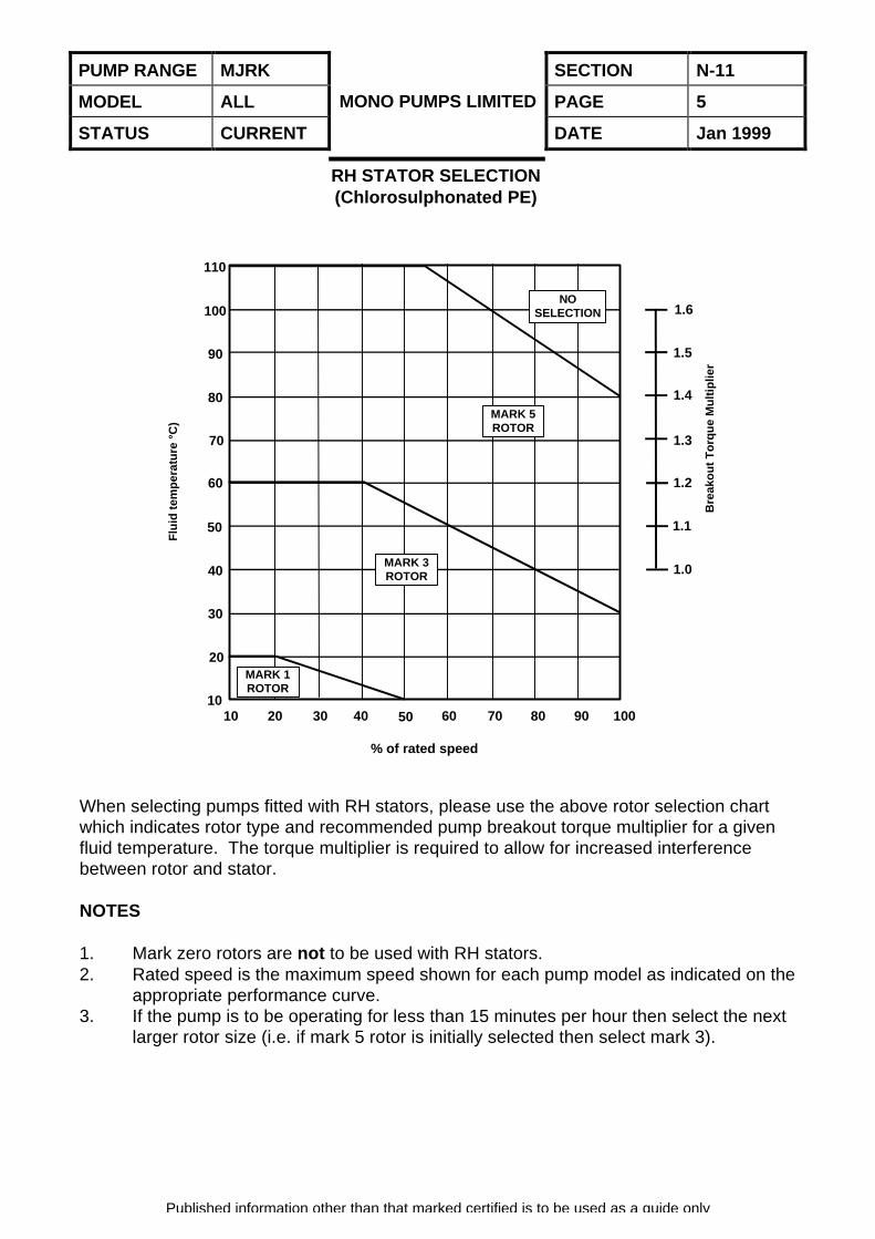
RH STATOR SELECTION(Chlorosulphonated PE)
When selecting pumps fitted with RH stators, please use the above rotor selection chartwhich indicates rotor type and recommended pump breakout torque multiplier for a givenfluid temperature. The torque multiplier is required to allow for increased interferencebetween rotor and stator.
NOTES
1. Mark zero rotors are not to be used with RH stators.2. Rated speed is the maximum speed shown for each pump model as indicated on the
appropriate performance curve.3. If the pump is to be operating for less than 15 minutes per hour then select the next
larger rotor size (i.e. if mark 5 rotor is initially selected then select mark 3).
MARK 1ROTOR
MARK 3ROTOR
MARK 5ROTOR
NOSELECTION 1.6
1.5
1.4
1.3
1.2
1.1
1.0
Bre
ako
ut
To
rqu
e M
ult
iplie
r10 20 30 40 50 60 70 80 90 100
% of rated speed
Flu
id t
emp
erat
ure
°C
)
110
100
90
80
70
60
50
40
30
20
10
PUMP RANGE MJRK SECTION N-11
MODEL ALL PAGE 6
STATUS CURRENT
MONO PUMPS LIMITED
DATE Jan 1999
Published information other than that marked certified is to be used as a guide only
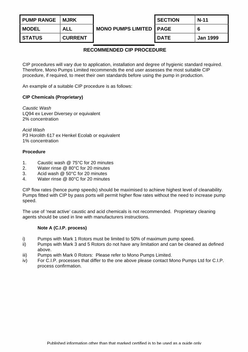
RECOMMENDED CIP PROCEDURE
CIP procedures will vary due to application, installation and degree of hygienic standard required.Therefore, Mono Pumps Limited recommends the end user assesses the most suitable CIPprocedure, if required, to meet their own standards before using the pump in production.
An example of a suitable CIP procedure is as follows:
CIP Chemicals (Proprietary)
Caustic WashLQ94 ex Lever Diversey or equivalent2% concentration
Acid WashP3 Horolith 617 ex Henkel Ecolab or equivalent1% concentration
Procedure
1. Caustic wash @ 75°C for 20 minutes2. Water rinse @ 80°C for 20 minutes3. Acid wash @ 50°C for 20 minutes4. Water rinse @ 80°C for 20 minutes
CIP flow rates (hence pump speeds) should be maximised to achieve highest level of cleanability.Pumps fitted with CIP by pass ports will permit higher flow rates without the need to increase pumpspeed.
The use of ‘neat active’ caustic and acid chemicals is not recommended. Proprietary cleaningagents should be used in line with manufacturers instructions.
Note A (C.I.P. process)
i) Pumps with Mark 1 Rotors must be limited to 50% of maximum pump speed.ii) Pumps with Mark 3 and 5 Rotors do not have any limitation and can be cleaned as defined
above.iii) Pumps with Mark 0 Rotors: Please refer to Mono Pumps Limited.iv) For C.I.P. processes that differ to the one above please contact Mono Pumps Ltd for C.I.P.
process confirmation.

MONO PUMPS LIMITED
RANGE(S) MJRK
MODEL N041
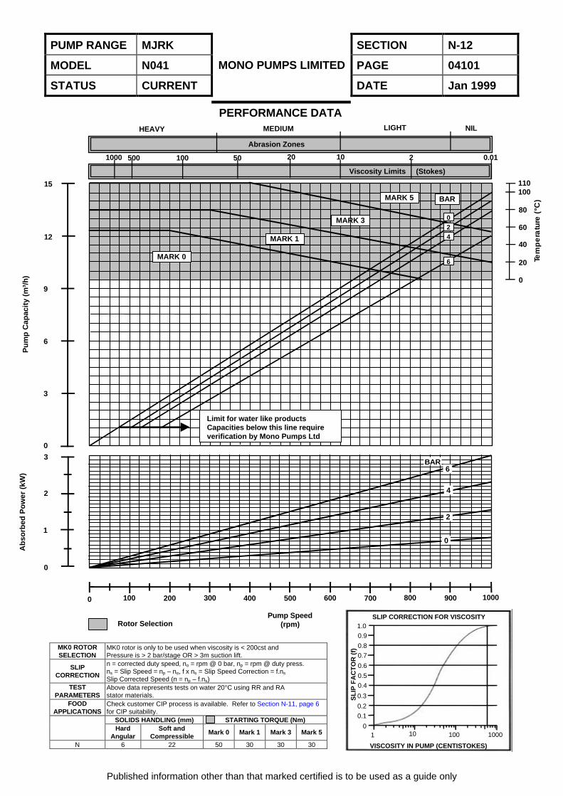
MAXIMUM CAPACITY 14.5 m³/h
MAXIMUM PRESSURE 6 Bar
MAXIMUM SPEED 1000 rpm
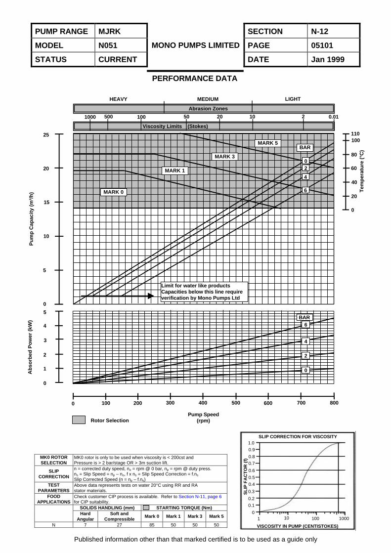
PUMP RANGE MJRK SECTION N-12
MODEL N041 PAGE 04101
STATUS CURRENT
MONO PUMPS LIMITED
DATE Jan 1999
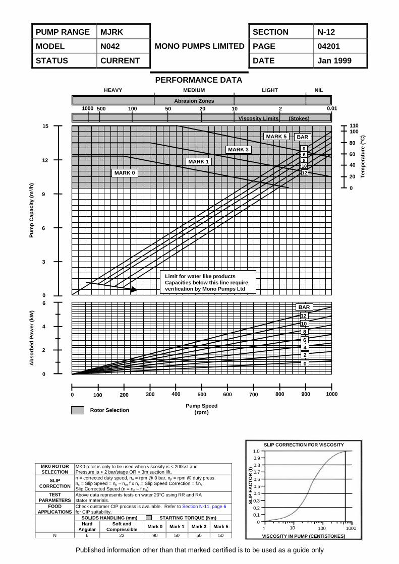
MK0 ROTORSELECTION
MK0 rotor is only to be used when viscosity is < 200cst andPressure is > 2 bar/stage OR > 3m suction lift.
SLIPCORRECTION
n = corrected duty speed, no = rpm @ 0 bar, np = rpm @ duty press.ns = Slip Speed = np – no, f x ns = Slip Speed Correction = f.ns
Slip Corrected Speed (n = np – f.ns)TEST
PARAMETERSAbove data represents tests on water 20°C using RR and RAstator materials.
FOODAPPLICATIONS
Check customer CIP process is available. Refer to Section N-11, page 6for CIP suitability.
SOLIDS HANDLING (mm) STARTING TORQUE (Nm)Hard
AngularSoft and
CompressibleMark 0 Mark 1 Mark 3 Mark 5
N 6 22 50 30 30 30
Published information other than that marked certified is to be used as a guide only
PERFORMANCE DATA
SLIP CORRECTION FOR VISCOSITY1.0
0.9
0.8
0.7
0.6
0.5
0.4
0.3
0.2
0.1
0
VISCOSITY IN PUMP (CENTISTOKES)
SL
IP F
AC
TO
R (
f)
1 10 100 1000
HEAVY MEDIUM LIGHT NIL
1000 500 100 50 20 10 2 0.01
Abrasion Zones
Viscosity Limits (Stokes)
MARK 0
MARK 1
MARK 3
MARK 5 BAR
024
6
15
12
9
6
3
0
Limit for water like productsCapacities below this line requireverification by Mono Pumps Ltd
0
1
2
3
0 100 200 300 400 500 600 700 800 900 1000
110100
80
60
40
20
0
Tem
pe
ratu
re (
°C)
Pu
mp
Cap
acit
y (m
³/h
)A
bso
rbed
Po
wer
(kW
)
Rotor SelectionPump Speed
(rpm)
0
2
4
6BAR
PUMP RANGE MJRK SECTION N-12
MODEL N041 PAGE 04102
STATUS CURRENT
MONO PUMPS LIMITED
DATE Jan 1999
Published information other than that marked certified is to be used as a guide only
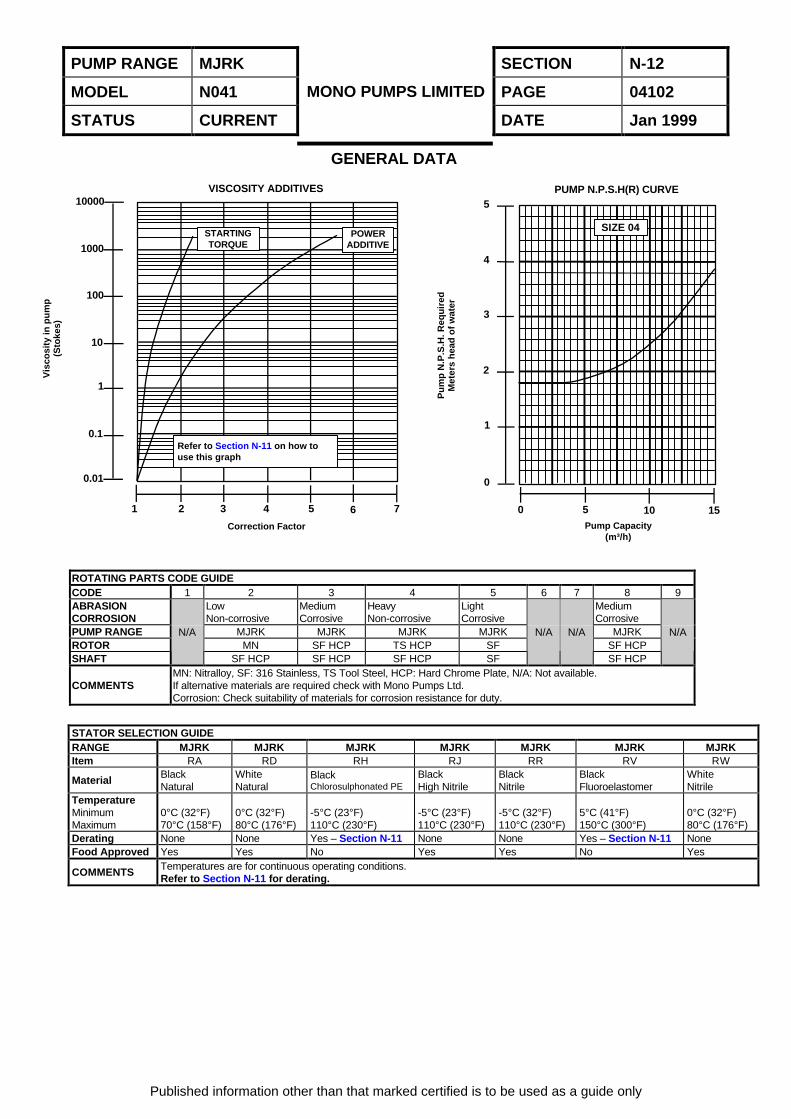
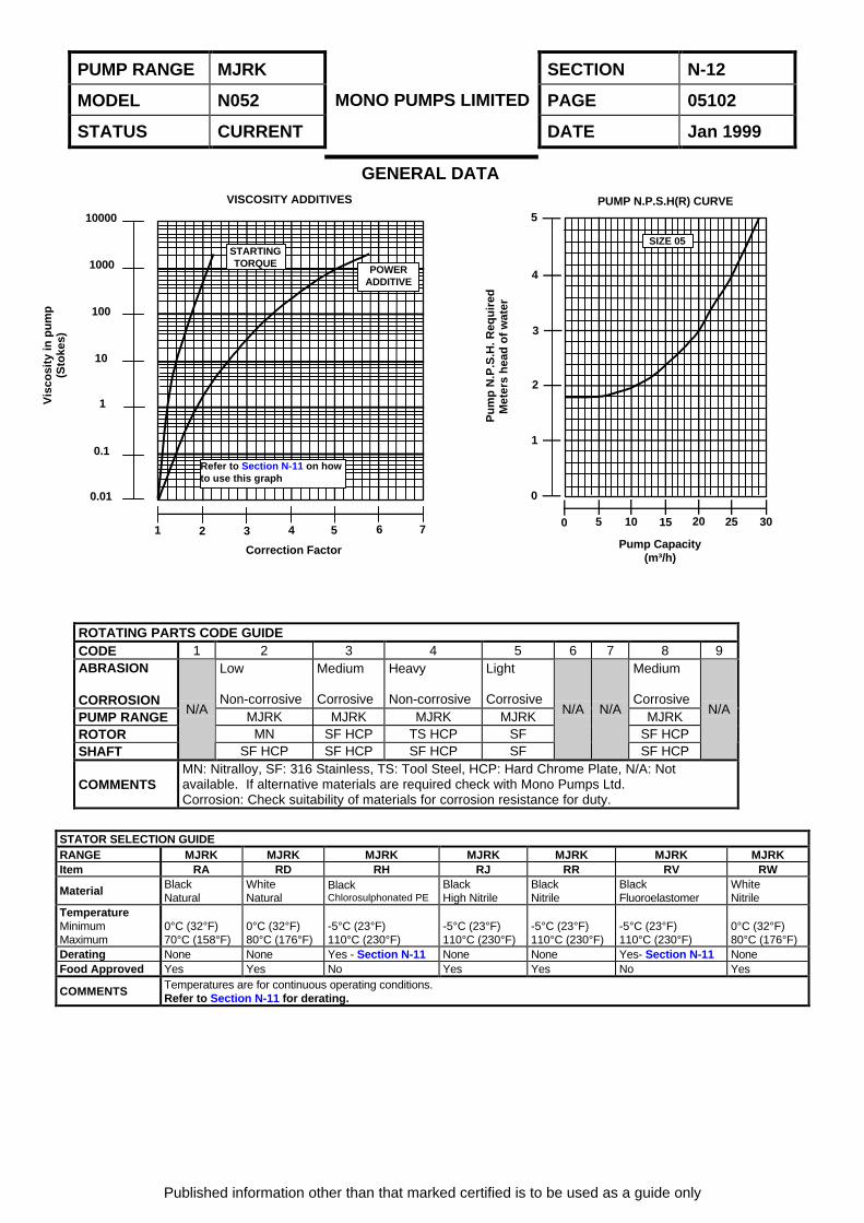
GENERAL DATA
ROTATING PARTS CODE GUIDECODE 1 2 3 4 5 6 7 8 9ABRASIONCORROSION
LowNon-corrosive
MediumCorrosive
HeavyNon-corrosive
LightCorrosive
MediumCorrosive
PUMP RANGE MJRK MJRK MJRK MJRK MJRKROTOR MN SF HCP TS HCP SF SF HCPSHAFT
N/A
SF HCP SF HCP SF HCP SF
N/A N/A
SF HCP
N/A
COMMENTSMN: Nitralloy, SF: 316 Stainless, TS Tool Steel, HCP: Hard Chrome Plate, N/A: Not available.If alternative materials are required check with Mono Pumps Ltd.Corrosion: Check suitability of materials for corrosion resistance for duty.
STATOR SELECTION GUIDERANGE MJRK MJRK MJRK MJRK MJRK MJRK MJRKItem RA RD RH RJ RR RV RW
Material BlackNatural
WhiteNatural
BlackChlorosulphonated PE
BlackHigh Nitrile
BlackNitrile
BlackFluoroelastomer
WhiteNitrile
TemperatureMinimumMaximum
0°C (32°F)70°C (158°F)
0°C (32°F)80°C (176°F)
-5°C (23°F)110°C (230°F)
-5°C (23°F)110°C (230°F)
-5°C (32°F)110°C (230°F)
5°C (41°F)150°C (300°F)
0°C (32°F)80°C (176°F)
Derating None None Yes – Section N-11 None None Yes – Section N-11 NoneFood Approved Yes Yes No Yes Yes No Yes
COMMENTS Temperatures are for continuous operating conditions.Refer to Section N-11 for derating.
SIZE 04POWER
ADDITIVESTARTINGTORQUE
Refer to Section N-11 on how touse this graph
1 2 3 4 5 6 7
Correction Factor
Vis
cosi
ty in
pu
mp
(Sto
kes)
10000
1000
100
10
1
0.1
0.01
0 5 10 15
0
1
2
3
4
5
Pump Capacity(m³/h)
Pu
mp
N.P
.S.H
. Req
uir
edM
eter
s h
ead
of
wat
er
VISCOSITY ADDITIVES PUMP N.P.S.H(R) CURVE
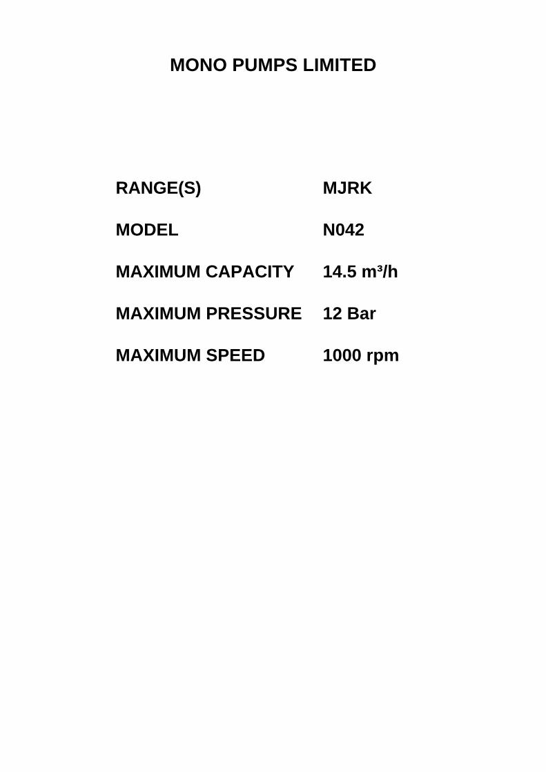
MONO PUMPS LIMITED
RANGE(S) MJRK
MODEL N042
MAXIMUM CAPACITY 14.5 m³/h
MAXIMUM PRESSURE 12 Bar
MAXIMUM SPEED 1000 rpm
PUMP RANGE MJRK SECTION N-12
MODEL N042 PAGE 04201
STATUS CURRENT
MONO PUMPS LIMITED
DATE Jan 1999
MK0 ROTORSELECTION
MK0 rotor is only to be used when viscosity is < 200cst andPressure is > 2 bar/stage OR > 3m suction lift.
SLIPCORRECTION
n = corrected duty speed, no = rpm @ 0 bar, np = rpm @ duty press.ns = Slip Speed = np – no, f x ns = Slip Speed Correction = f.ns
Slip Corrected Speed (n = np – f.ns)TEST
PARAMETERSAbove data represents tests on water 20°C using RR and RAstator materials.
FOODAPPLICATIONS
Check customer CIP process is available. Refer to Section N-11, page 6for CIP suitability.
SOLIDS HANDLING (mm) STARTING TORQUE (Nm)Hard
AngularSoft and
CompressibleMark 0 Mark 1 Mark 3 Mark 5
N 6 22 90 50 50 50
Published information other than that marked certified is to be used as a guide only
PERFORMANCE DATA
SLIP CORRECTION FOR VISCOSITY1.0
0.9
0.8
0.7
0.6
0.5
0.4
0.3
0.2
0.1
0
VISCOSITY IN PUMP (CENTISTOKES)
SL
IP F
AC
TO
R (
f)
1 10 100 1000
HEAVY MEDIUM LIGHT NIL
Abrasion Zones
Viscosity Limits (Stokes)
1000 500 100 50 20 10 2 0.01
BARMARK 5
MARK 3 0
MARK 1
MARK 0
681012
110100
80
60
40
20
0
Tem
per
atu
re (
°C)
Ab
sorb
ed P
ow
er (
kW)
Pu
mp
Cap
acit
y (m
³/h
)
15
12
9
6
3
06
4
2
0
0 100 200 300 400 500 600 700 800 900 1000
Pump Speed(rpm)Rotor Selection
BAR
1210
8
642
0
Limit for water like productsCapacities below this line requireverification by Mono Pumps Ltd
PUMP RANGE MJRK SECTION N-12
MODEL N042 PAGE 04202
STATUS CURRENT
MONO PUMPS LIMITED
DATE Jan 1999
Published information other than that marked certified is to be used as a guide only
GENERAL DATA
ROTATING PARTS CODE GUIDECODE 1 2 3 4 5 6 7 8 9ABRASION
CORROSION
Low
Non-corrosive
Medium
Corrosive
Heavy
Non-corrosive
Light
Corrosive
Medium
CorrosivePUMP RANGE MJRK MJRK MJRK MJRK MJRKROTOR MN SF HCP TS HCP SF SF HCPSHAFT
N/A
SF HCP SF HCP SF HCP SF
N/A N/A
SF HCP
N/A
COMMENTSMN: Nitralloy, SF: 316 Stainless, TS: Tool Steel, HCP: Hard Chrome Plate, N/A: Not available.If alternative materials are required check with Mono Pumps Ltd.Corrosion: Check suitability of materials for corrosion resistance for duty.
STATOR SELECTION GUIDERANGE MJRK MJRK MJRK MJRK MJRK MJRKItem RA RD RH RJ RR RW
Material BlackNatural
WhiteNatural
BlackChlorosulphonated PE
BlackHigh Nitrile
BlackNitrile
WhiteNitrile
TemperatureMinimumMaximum
0°C (32°F)70°C (158°F)
0°C (32°F)80°C (176°F)
-5°C (23°F)110°C (230°F)
-5°C (23°F)110°C (230°F)
-5°C (32°F)110°C (230°F)
0°C (32°F)80°C (176°F)
Derating None None Yes – Section N-11 None None NoneFood Approved Yes Yes No Yes Yes Yes
COMMENTS Temperatures are for continuous operating conditions.Refer to Section N-11 for derating.
Correction Factor
1 2 3 4 5 6 7
0.01
0.1
1
10
100
1000
10000VISCOSITY ADDITIVES PUMP N.P.S.H(R) CURVE
SIZE 04
5
4
3
2
1
0
0 5 10 15Pump Capacity
(m³/h)
Pu
mp
N.P
.S.H
. Req
uir
edM
eter
s h
ead
of
wat
er
Vis
cosi
ty in
pu
mp
(Sto
kes)
STARTINGTORQUE
POWERADDITIVE
Refer to Section N-11 on howto use this graph

MONO PUMPS LIMITED
RANGE(S) MJRK
MODEL N051
MAXIMUM CAPACITY 24 m³/h
MAXIMUM PRESSURE 6 Bar
MAXIMUM SPEED 800 rpm
PUMP RANGE MJRK SECTION N-12
MODEL N051 PAGE 05101
STATUS CURRENT
MONO PUMPS LIMITED
DATE Jan 1999
MK0 ROTORSELECTION
MK0 rotor is only to be used when viscosity is < 200cst andPressure is > 2 bar/stage OR > 3m suction lift.
SLIPCORRECTION
n = corrected duty speed, no = rpm @ 0 bar, np = rpm @ duty press.ns = Slip Speed = np – no, f x ns = Slip Speed Correction = f.ns
Slip Corrected Speed (n = np – f.ns)TEST
PARAMETERSAbove data represents tests on water 20°C using RR and RAstator materials.
FOODAPPLICATIONS
Check customer CIP process is available. Refer to Section N-11, page 6for CIP suitability.
SOLIDS HANDLING (mm) STARTING TORQUE (Nm)Hard
AngularSoft and
CompressibleMark 0 Mark 1 Mark 3 Mark 5
N 7 27 85 50 50 50
Published information other than that marked certified is to be used as a guide only
PERFORMANCE DATA
SLIP CORRECTION FOR VISCOSITY1.0
0.9
0.8
0.7
0.6
0.5
0.4
0.3
0.2
0.1
0
VISCOSITY IN PUMP (CENTISTOKES)
SL
IP F
AC
TO
R (
f)
1 10 100 1000
Rotor SelectionPump Speed
(rpm)
0 100 200 300 400 500 600 700 800
0
1
2
3
4
5
0
5
10
15
20
25 110100
80
60
40
20
0
Tem
per
atu
re (
°C)
Pu
mp
Cap
acit
y (m
³/h
)
HEAVY MEDIUM LIGHT
1000 500 100 50 20 10 2 0.01
Limit for water like productsCapacities below this line requireverification by Mono Pumps Ltd
MARK 0
MARK 1
MARK 3
MARK 5BAR
02
4
6
BAR6
4
2
0Ab
sorb
ed P
ow
er (
kW)
Abrasion Zones
Viscosity Limits (Stokes)
PUMP RANGE MJRK SECTION N-12
MODEL N052 PAGE 05102
STATUS CURRENT
MONO PUMPS LIMITED
DATE Jan 1999
Published information other than that marked certified is to be used as a guide only
GENERAL DATA
ROTATING PARTS CODE GUIDECODE 1 2 3 4 5 6 7 8 9ABRASION
CORROSION
Low
Non-corrosive
Medium
Corrosive
Heavy
Non-corrosive
Light
Corrosive
Medium
CorrosivePUMP RANGE MJRK MJRK MJRK MJRK MJRKROTOR MN SF HCP TS HCP SF SF HCPSHAFT
N/A
SF HCP SF HCP SF HCP SF
N/A N/A
SF HCP
N/A
COMMENTSMN: Nitralloy, SF: 316 Stainless, TS: Tool Steel, HCP: Hard Chrome Plate, N/A: Notavailable. If alternative materials are required check with Mono Pumps Ltd.Corrosion: Check suitability of materials for corrosion resistance for duty.
STATOR SELECTION GUIDERANGE MJRK MJRK MJRK MJRK MJRK MJRK MJRKItem RA RD RH RJ RR RV RW
Material BlackNatural
WhiteNatural
BlackChlorosulphonated PE
BlackHigh Nitrile
BlackNitrile
BlackFluoroelastomer
WhiteNitrile
TemperatureMinimumMaximum
0°C (32°F)70°C (158°F)
0°C (32°F)80°C (176°F)
-5°C (23°F)110°C (230°F)
-5°C (23°F)110°C (230°F)
-5°C (23°F)110°C (230°F)
-5°C (23°F)110°C (230°F)
0°C (32°F)80°C (176°F)
Derating None None Yes - Section N-11 None None Yes- Section N-11 NoneFood Approved Yes Yes No Yes Yes No Yes
COMMENTS Temperatures are for continuous operating conditions.Refer to Section N-11 for derating.
Refer to Section N-11 on howto use this graph
STARTINGTORQUE
POWERADDITIVE
SIZE 05
0 5 10 15 20 25 30
0
1
2
3
4
5PUMP N.P.S.H(R) CURVE
1 2 3 4 5 6 7
0.01
0.1
1
10
100
1000
10000
VISCOSITY ADDITIVES
Vis
cosi
ty in
pu
mp
(Sto
kes)
Pu
mp
N.P
.S.H
. Req
uir
edM
eter
s h
ead
of
wat
er
Pump Capacity(m³/h)
Correction Factor

MONO PUMPS LIMITED
RANGE(S) MJRK
MODEL N052
MAXIMUM CAPACITY 23 m³/h
MAXIMUM PRESSURE 12 Bar
MAXIMUM SPEED 800 rpm
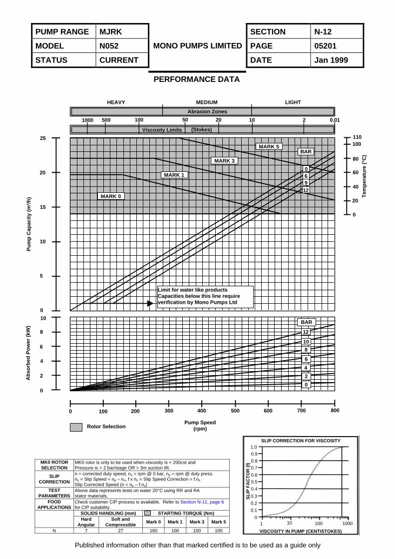
PUMP RANGE MJRK SECTION N-12
MODEL N052 PAGE 05201
STATUS CURRENT
MONO PUMPS LIMITED
DATE Jan 1999
MK0 ROTORSELECTION
MK0 rotor is only to be used when viscosity is < 200cst andPressure is > 2 bar/stage OR > 3m suction lift.
SLIPCORRECTION
n = corrected duty speed, no = rpm @ 0 bar, np = rpm @ duty press.ns = Slip Speed = np – no, f x ns = Slip Speed Correction = f.ns
Slip Corrected Speed (n = np – f.ns)TEST
PARAMETERSAbove data represents tests on water 20°C using RR and RAstator materials.
FOODAPPLICATIONS
Check customer CIP process is available. Refer to Section N-11, page 6for CIP suitability.
SOLIDS HANDLING (mm) STARTING TORQUE (Nm)Hard
AngularSoft and
CompressibleMark 0 Mark 1 Mark 3 Mark 5
N 7 27 160 100 100 100
Published information other than that marked certified is to be used as a guide only
PERFORMANCE DATA
SLIP CORRECTION FOR VISCOSITY1.0
0.9
0.8
0.7
0.6
0.5
0.4
0.3
0.2
0.1
0
VISCOSITY IN PUMP (CENTISTOKES)
SL
IP F
AC
TO
R (
f)
1 10 100 1000
HEAVY MEDIUM LIGHT
MARK 0
MARK 1
MARK 3
MARK 5BAR
Limit for water like productsCapacities below this line requireverification by Mono Pumps Ltd
25
20
15
10
5
0
10
8
6
2
0
Rotor SelectionPump Speed
(rpm)
0 100
4
200 300 400 500 600 700 800
BAR
12
10
8
6
4
2
0
Abrasion Zones
Viscosity Limits (Stokes)
1000 500 100 50 20 10 2 0.01
069
12
110100
80
60
40
20
0
Tem
per
atu
re (
°C)
Pu
mp
Cap
acit
y (m
³/h
)A
bso
rbed
Po
wer
(kW
)
PUMP RANGE MJRK SECTION N-12
MODEL N052 PAGE 05202
STATUS CURRENT
MONO PUMPS LIMITED
DATE Jan 1999
Published information other than that marked certified is to be used as a guide only
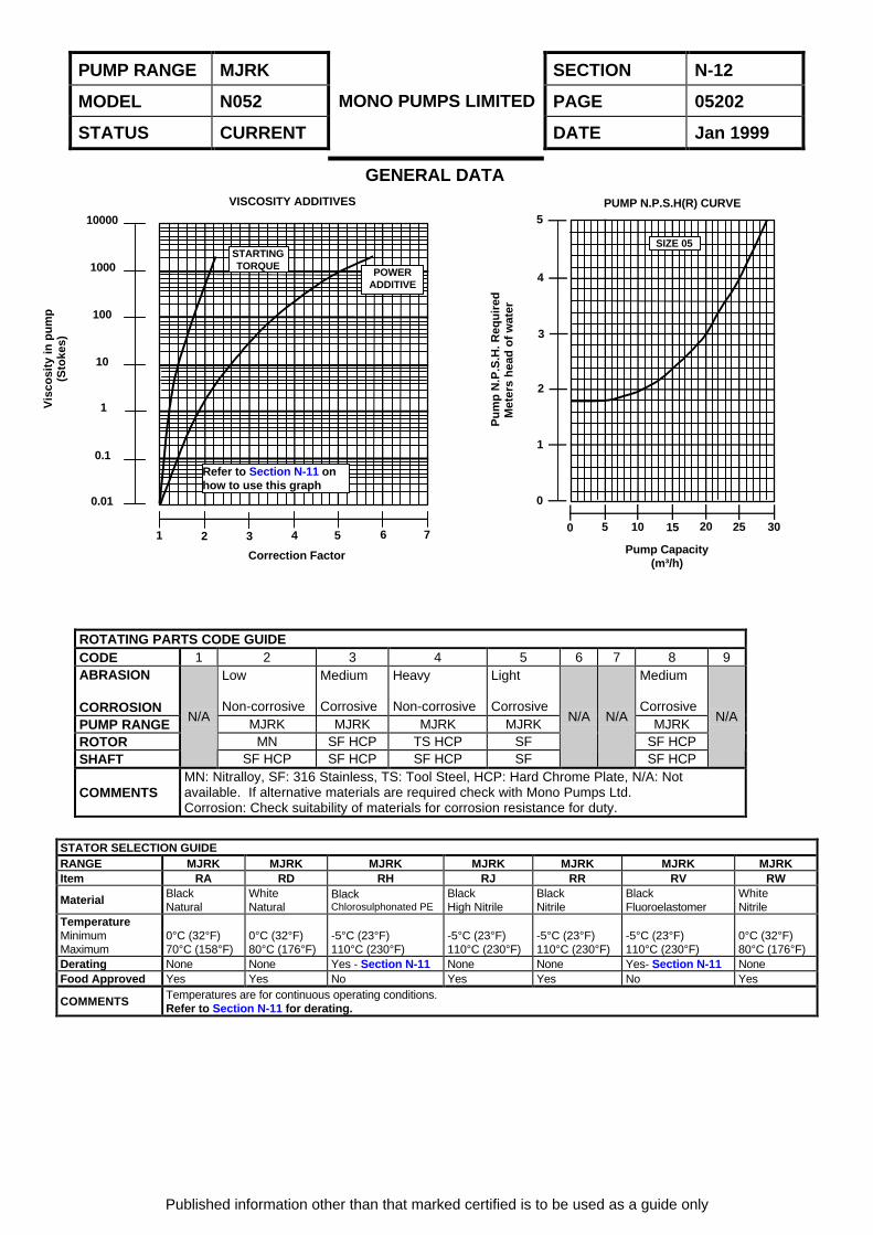
GENERAL DATA
ROTATING PARTS CODE GUIDECODE 1 2 3 4 5 6 7 8 9ABRASION
CORROSION
Low
Non-corrosive
Medium
Corrosive
Heavy
Non-corrosive
Light
Corrosive
Medium
CorrosivePUMP RANGE MJRK MJRK MJRK MJRK MJRKROTOR MN SF HCP TS HCP SF SF HCPSHAFT
N/A
SF HCP SF HCP SF HCP SF
N/A N/A
SF HCP
N/A
COMMENTSMN: Nitralloy, SF: 316 Stainless, TS: Tool Steel, HCP: Hard Chrome Plate, N/A: Notavailable. If alternative materials are required check with Mono Pumps Ltd.Corrosion: Check suitability of materials for corrosion resistance for duty.
STATOR SELECTION GUIDERANGE MJRK MJRK MJRK MJRK MJRK MJRK MJRKItem RA RD RH RJ RR RV RW
Material BlackNatural
WhiteNatural
BlackChlorosulphonated PE
BlackHigh Nitrile
BlackNitrile
BlackFluoroelastomer
WhiteNitrile
TemperatureMinimumMaximum
0°C (32°F)70°C (158°F)
0°C (32°F)80°C (176°F)
-5°C (23°F)110°C (230°F)
-5°C (23°F)110°C (230°F)
-5°C (23°F)110°C (230°F)
-5°C (23°F)110°C (230°F)
0°C (32°F)80°C (176°F)
Derating None None Yes - Section N-11 None None Yes- Section N-11 NoneFood Approved Yes Yes No Yes Yes No Yes
COMMENTS Temperatures are for continuous operating conditions.Refer to Section N-11 for derating.
Refer to Section N-11 onhow to use this graph
STARTINGTORQUE
POWERADDITIVE
SIZE 05
0 5 10 15 20 25 30
0
1
2
3
4
5PUMP N.P.S.H(R) CURVE
1 2 3 4 5 6 7
0.01
0.1
1
10
100
1000
10000
VISCOSITY ADDITIVES
Vis
cosi
ty in
pu
mp
(Sto
kes)
Pu
mp
N.P
.S.H
. Req
uir
edM
eter
s h
ead
of
wat
er
Pump Capacity(m³/h)
Correction Factor

MONO PUMPS LIMITED
RANGE(S) MJRK
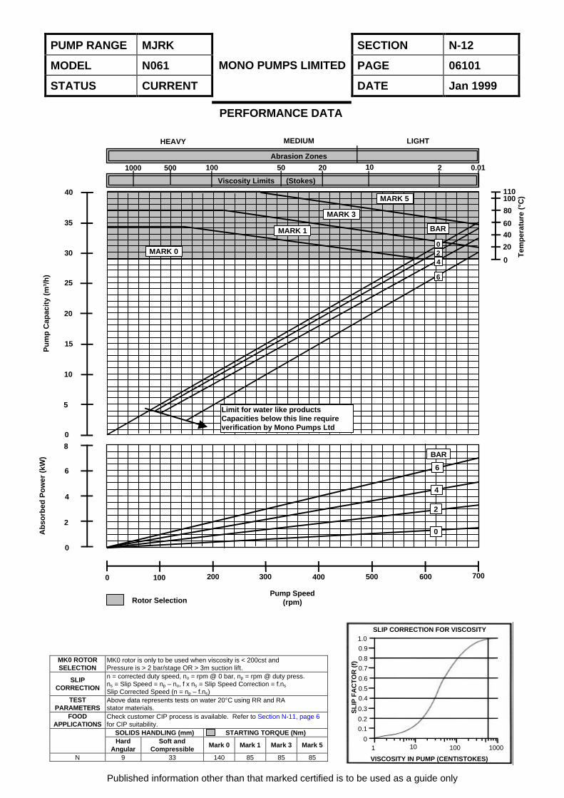
MODEL N061
MAXIMUM CAPACITY 35 m³/h
MAXIMUM PRESSURE 6 Bar
MAXIMUM SPEED 700 rpm
PUMP RANGE MJRK SECTION N-12
MODEL N061 PAGE 06101
STATUS CURRENT
MONO PUMPS LIMITED
DATE Jan 1999
MK0 ROTORSELECTION
MK0 rotor is only to be used when viscosity is < 200cst andPressure is > 2 bar/stage OR > 3m suction lift.
SLIPCORRECTION
n = corrected duty speed, no = rpm @ 0 bar, np = rpm @ duty press.ns = Slip Speed = np – no, f x ns = Slip Speed Correction = f.ns
Slip Corrected Speed (n = np – f.ns)TEST
PARAMETERSAbove data represents tests on water 20°C using RR and RAstator materials.
FOODAPPLICATIONS
Check customer CIP process is available. Refer to Section N-11, page 6for CIP suitability.
SOLIDS HANDLING (mm) STARTING TORQUE (Nm)Hard
AngularSoft and
CompressibleMark 0 Mark 1 Mark 3 Mark 5
N 9 33 140 85 85 85
Published information other than that marked certified is to be used as a guide only
PERFORMANCE DATA
SLIP CORRECTION FOR VISCOSITY1.0
0.9
0.8
0.7
0.6
0.5
0.4
0.3
0.2
0.1
0
VISCOSITY IN PUMP (CENTISTOKES)
SL
IP F
AC
TO
R (
f)
1 10 100 1000
HEAVY MEDIUM LIGHT
Abrasion Zones
Viscosity Limits (Stokes)
1000 500 100 50 20 10 2 0.01
Rotor SelectionPump Speed
(rpm)
110100
80
60
40
20
0
Tem
per
atu
re (
°C)
Ab
sorb
ed P
ow
er (
kW)
Pu
mp
Cap
acit
y (m
³/h
)
40
35
30
25
20
15
10
5
0
8
6
4
2
0
0 100 200 300 400 500 600 700
BAR
6
4
2
0
Limit for water like productsCapacities below this line requireverification by Mono Pumps Ltd
MARK 0
MARK 1
MARK 3
MARK 5
BAR
024
6
PUMP RANGE MJRK SECTION N-12
MODEL N061 PAGE 06102
STATUS CURRENT
MONO PUMPS LIMITED
DATE Jan 1999
Published information other than that marked certified is to be used as a guide only
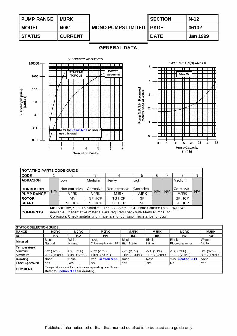
GENERAL DATA
ROTATING PARTS CODE GUIDECODE 1 2 3 4 5 6 7 8 9ABRASION
CORROSION
Low
Non-corrosive
Medium
Corrosive
Heavy
Non-corrosive
Light
Corrosive
Medium
CorrosivePUMP RANGE MJRK MJRK MJRK MJRK MJRKROTOR MN SF HCP TS HCP SF SF HCPSHAFT
N/A
SF HCP SF HCP SF HCP SF
N/A N/A
SF HCP
N/A
COMMENTSMN: Nitralloy, SF: 316 Stainless, TS: Tool Steel, HCP: Hard Chrome Plate, N/A: Notavailable. If alternative materials are required check with Mono Pumps Ltd.Corrosion: Check suitability of materials for corrosion resistance for duty.
STATOR SELECTION GUIDERANGE MJRK MJRK MJRK MJRK MJRK MJRK MJRKItem RA RD RH RJ RR RV RW
Material BlackNatural
WhiteNatural
BlackChlorosulphonated PE
BlackHigh Nitrile
BlackNitrile
BlackFluoroelastomer
WhiteNitrile
TemperatureMinimumMaximum
0°C (32°F)70°C (158°F)
0°C (32°F)80°C (176°F)
-5°C (23°F)110°C (230°F)
-5°C (23°F)110°C (230°F)
-5°C (23°F)110°C (230°F)
-5°C (23°F)110°C (230°F)
0°C (32°F)80°C (176°F)
Derating None None Yes - Section N-11 None None Yes - Section N-11 NoneFood Approved Yes Yes No Yes Yes No Yes
COMMENTS Temperatures are for continuous operating conditions.Refer to Section N-11 for derating.
SIZE 06
Refer to Section N-11 on how touse this graph
STARTINGTORQUE
POWERADDITIVE
1 2 3 4 5 6 7
0.01
0.1
1
10
100
1000
100000VISCOSITY ADDITIVES
0 5 10 15 20 25 30 35
0
1
2
3
4
5PUMP N.P.S.H(R) CURVE
Pump Capacity(m³/h)Correction Factor
Vis
cosi
ty in
pu
mp
(Sto
kes)
Pu
mp
N.P
.S.H
. Req
uir
edM
eter
s h
ead
of
wat
er
MONO PUMPS LIMITED
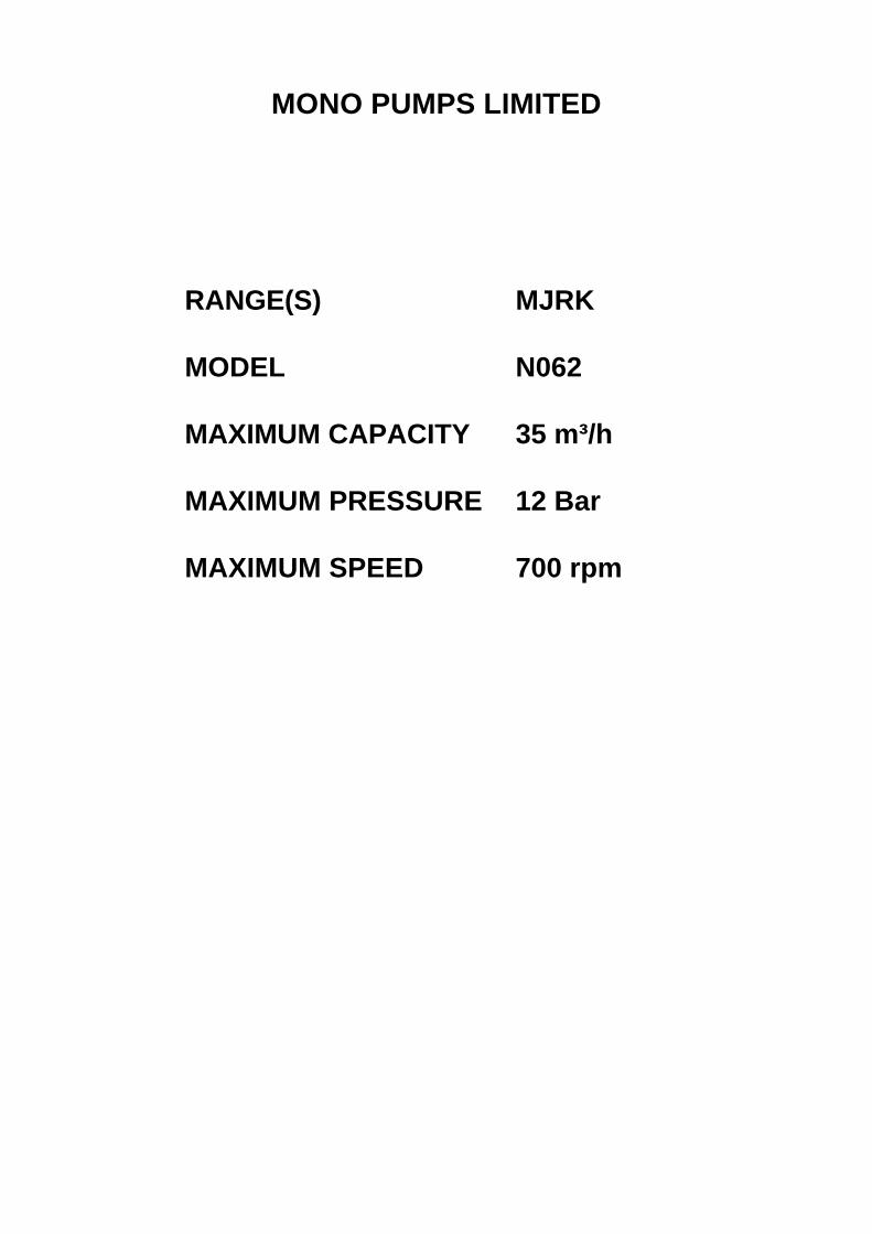
RANGE(S) MJRK
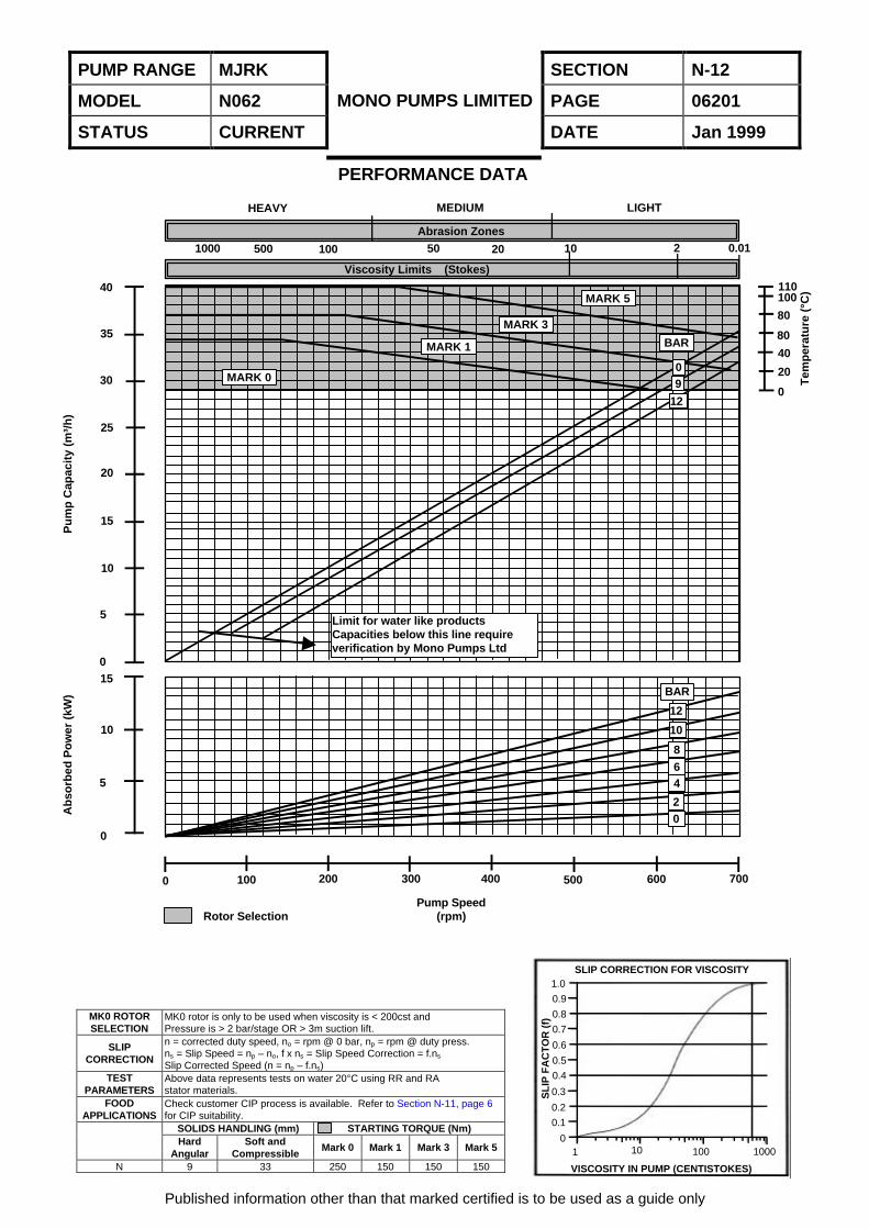
MODEL N062
MAXIMUM CAPACITY 35 m³/h
MAXIMUM PRESSURE 12 Bar
MAXIMUM SPEED 700 rpm
PUMP RANGE MJRK SECTION N-12
MODEL N062 PAGE 06201
STATUS CURRENT
MONO PUMPS LIMITED
DATE Jan 1999
MK0 ROTORSELECTION
MK0 rotor is only to be used when viscosity is < 200cst andPressure is > 2 bar/stage OR > 3m suction lift.
SLIPCORRECTION
n = corrected duty speed, no = rpm @ 0 bar, np = rpm @ duty press.ns = Slip Speed = np – no, f x ns = Slip Speed Correction = f.ns
Slip Corrected Speed (n = np – f.ns)TEST
PARAMETERSAbove data represents tests on water 20°C using RR and RAstator materials.
FOODAPPLICATIONS
Check customer CIP process is available. Refer to Section N-11, page 6for CIP suitability.
SOLIDS HANDLING (mm) STARTING TORQUE (Nm)Hard
AngularSoft and
CompressibleMark 0 Mark 1 Mark 3 Mark 5
N 9 33 250 150 150 150
Published information other than that marked certified is to be used as a guide only
PERFORMANCE DATA
SLIP CORRECTION FOR VISCOSITY1.0
0.9
0.8
0.7
0.6
0.5
0.4
0.3
0.2
0.1
0
VISCOSITY IN PUMP (CENTISTOKES)
SL
IP F
AC
TO
R (
f)
1 10 100 1000
HEAVY MEDIUM LIGHT
Abrasion Zones
Viscosity Limits (Stokes)
1000 500 100 50 20 10 2 0.01
110100
80
80
40
20
0
Tem
per
atu
re (
°C)
Pu
mp
Cap
acit
y (m
³/h
)
40
35
30
25
20
15
10
5
015
10
5
0
Ab
sorb
ed P
ow
er (
kW)
0 100 200 300 400 500 600 700
Pump Speed(rpm)Rotor Selection
MARK 0
MARK 1
MARK 3
MARK 5
BAR
09
12
Limit for water like productsCapacities below this line requireverification by Mono Pumps Ltd
BAR
12
10
864
20

PUMP RANGE MJRK SECTION N-12
MODEL N062 PAGE 06202
STATUS CURRENT
MONO PUMPS LIMITED
DATE Jan 1999
Published information other than that marked certified is to be used as a guide only
GENERAL DATA
ROTATING PARTS CODE GUIDECODE 1 2 3 4 5 6 7 8 9ABRASION
CORROSION
Low
Non-corrosive
Medium
Corrosive
Heavy
Non-corrosive
Light
Corrosive
Medium
CorrosivePUMP RANGE MJRK MJRK MJRK MJRK MJRKROTOR MN SF HCP TS HCP SF SF HCPSHAFT
N/A
SF HCP SF HCP SF HCP SF
N/A N/A
SF HCP
N/A
COMMENTSMN: Nitralloy, SF: 316 Stainless, TS: Tool Steel, HCP: Hard Chrome Plate, N/A: Notavailable. If alternative materials are required check with Mono Pumps Ltd.Corrosion: Check suitability of materials for corrosion resistance for duty.
STATOR SELECTION GUIDERANGE MJRK MJRK MJRK MJRK MJRK MJRK MJRKItem RA RD RH RJ RR RV RW
Material BlackNatural
WhiteNatural
BlackChlorosulphonated PE
BlackHigh Nitrile
BlackNitrile
BlackFluoroelastomer
WhiteNitrile
TemperatureMinimumMaximum
0°C (32°F)70°C (158°F)
0°C (32°F)80°C (176°F)
-5°C (23°F)110°C (230°F)
-5°C (23°F)110°C (230°F)
-5°C (23°F)110°C (230°F)
-5°C (23°F)110°C (230°F)
0°C (32°F)80°C (176°F)
Derating None None Yes - Section N-11 None None Yes - Section N-11 NoneFood Approved Yes Yes No Yes Yes No Yes
COMMENTS Temperatures are for continuous operating conditions.Refer to Section N-11 for derating.
SIZE 06
Refer to Section N-11 on how touse this graph
STARTINGTORQUE
POWERADDITIVE
1 2 3 4 5 6 7
0.01
0.1
1
10
100
1000
100000VISCOSITY ADDITIVES
0 5 10 15 20 25 30 35
0
1
2
3
4
5PUMP N.P.S.H(R) CURVE
Pump Capacity(m³/h)Correction Factor
Vis
cosi
ty in
pu
mp
(Sto
kes)
Pu
mp
N.P
.S.H
. Req
uir
edM
eter
s h
ead
of
wat
er

MONO PUMPS LIMITED
RANGE(S) MJRK
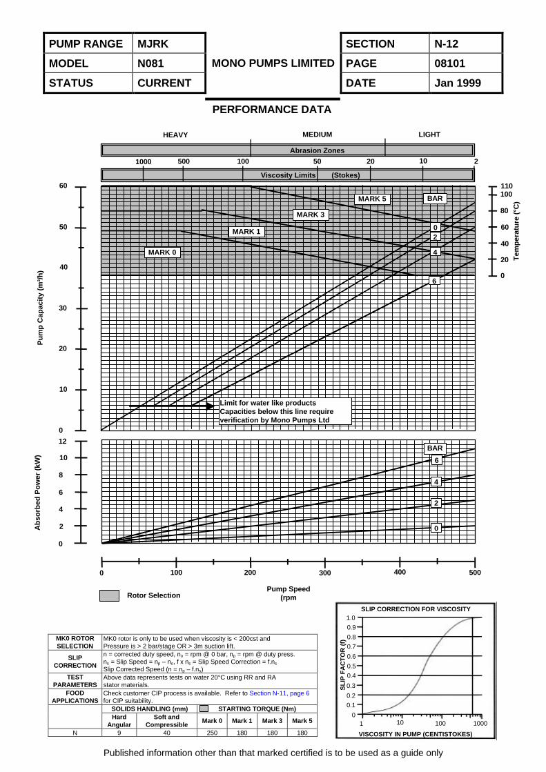
MODEL N081
MAXIMUM CAPACITY 58 m³/h
MAXIMUM PRESSURE 6 Bar
MAXIMUM SPEED 500 rpm
PUMP RANGE MJRK SECTION N-12
MODEL N081 PAGE 08101
STATUS CURRENT
MONO PUMPS LIMITED
DATE Jan 1999
MK0 ROTORSELECTION
MK0 rotor is only to be used when viscosity is < 200cst andPressure is > 2 bar/stage OR > 3m suction lift.
SLIPCORRECTION
n = corrected duty speed, no = rpm @ 0 bar, np = rpm @ duty press.ns = Slip Speed = np – no, f x ns = Slip Speed Correction = f.ns
Slip Corrected Speed (n = np – f.ns)TEST
PARAMETERSAbove data represents tests on water 20°C using RR and RAstator materials.
FOODAPPLICATIONS
Check customer CIP process is available. Refer to Section N-11, page 6for CIP suitability.
SOLIDS HANDLING (mm) STARTING TORQUE (Nm)Hard
AngularSoft and
CompressibleMark 0 Mark 1 Mark 3 Mark 5
N 9 40 250 180 180 180
Published information other than that marked certified is to be used as a guide only
PERFORMANCE DATA
SLIP CORRECTION FOR VISCOSITY1.0
0.9
0.8
0.7
0.6
0.5
0.4
0.3
0.2
0.1
0
VISCOSITY IN PUMP (CENTISTOKES)
SL
IP F
AC
TO
R (
f)
1 10 100 1000
HEAVY MEDIUM LIGHT
Abrasion Zones
Viscosity Limits (Stokes)
Rotor SelectionPump Speed
(rpm
MARK 0
MARK 1
MARK 3
MARK 5 BAR
Limit for water like productsCapacities below this line requireverification by Mono Pumps Ltd
BAR
6
4
2
0
0 100 200 300 400 500
0
2
4
6
8
10
12
0
10
20
30
40
50
60
Pu
mp
Cap
acit
y (m
³/h
)
110100
80
60
40
20
0
Tem
per
atu
re (
°C)
Ab
sorb
ed P
ow
er (
kW)
1000 500 100 50 20 10 2
02
4
6
PUMP RANGE MJRK SECTION N-12
MODEL N081 PAGE 08102
STATUS CURRENT
MONO PUMPS LIMITED
DATE Jan 1999
Published information other than that marked certified is to be used as a guide only
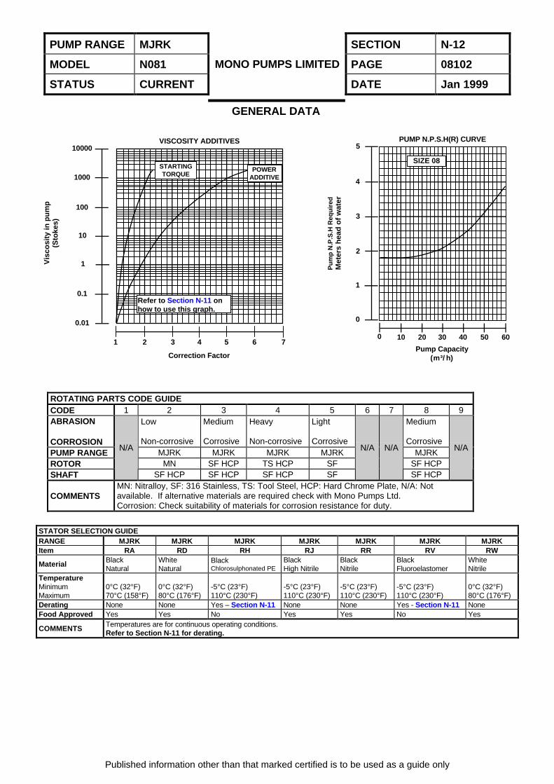
GENERAL DATA
ROTATING PARTS CODE GUIDECODE 1 2 3 4 5 6 7 8 9ABRASION
CORROSION
Low
Non-corrosive
Medium
Corrosive
Heavy
Non-corrosive
Light
Corrosive
Medium
CorrosivePUMP RANGE MJRK MJRK MJRK MJRK MJRKROTOR MN SF HCP TS HCP SF SF HCPSHAFT
N/A
SF HCP SF HCP SF HCP SF
N/A N/A
SF HCP
N/A
COMMENTSMN: Nitralloy, SF: 316 Stainless, TS: Tool Steel, HCP: Hard Chrome Plate, N/A: Notavailable. If alternative materials are required check with Mono Pumps Ltd.Corrosion: Check suitability of materials for corrosion resistance for duty.
STATOR SELECTION GUIDERANGE MJRK MJRK MJRK MJRK MJRK MJRK MJRKItem RA RD RH RJ RR RV RW
Material BlackNatural
WhiteNatural
BlackChlorosulphonated PE
BlackHigh Nitrile
BlackNitrile
BlackFluoroelastomer
WhiteNitrile
TemperatureMinimumMaximum
0°C (32°F)70°C (158°F)
0°C (32°F)80°C (176°F)
-5°C (23°F)110°C (230°F)
-5°C (23°F)110°C (230°F)
-5°C (23°F)110°C (230°F)
-5°C (23°F)110°C (230°F)
0°C (32°F)80°C (176°F)
Derating None None Yes – Section N-11 None None Yes - Section N-11 NoneFood Approved Yes Yes No Yes Yes No Yes
COMMENTS Temperatures are for continuous operating conditions.Refer to Section N-11 for derating.
Refer to Section N-11 onhow to use this graph.
STARTINGTORQUE
POWERADDITIVE
1 2 3 4 5 6 7
0.01
0.1
1
10
100
1000
10000VISCOSITY ADDITIVES PUMP N.P.S.H(R) CURVE
0 10 20 30 40 50 60
0
1
2
3
4
5
SIZE 08
Pump Capacity(m³/h)
Pu
mp
N.P
.S.H
Req
uir
edM
eter
s h
ead
of
wat
er
Vis
cosi
ty in
pu
mp
(Sto
kes)
Correction Factor

MONO PUMPS LIMITED
RANGE(S) MJRK
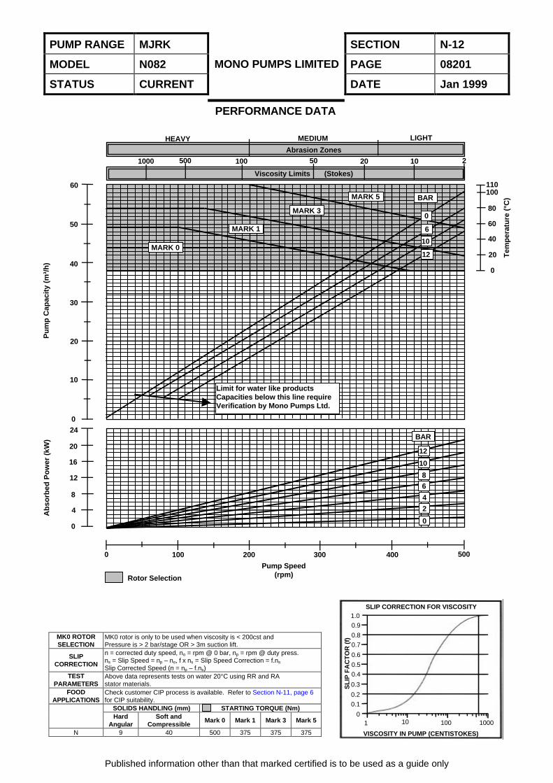
MODEL N082
MAXIMUM CAPACITY 58 m³/h
MAXIMUM PRESSURE 12 Bar
MAXIMUM SPEED 500 rpm
PUMP RANGE MJRK SECTION N-12
MODEL N082 PAGE 08201
STATUS CURRENT
MONO PUMPS LIMITED
DATE Jan 1999
MK0 ROTORSELECTION
MK0 rotor is only to be used when viscosity is < 200cst andPressure is > 2 bar/stage OR > 3m suction lift.
SLIPCORRECTION
n = corrected duty speed, no = rpm @ 0 bar, np = rpm @ duty press.ns = Slip Speed = np – no, f x ns = Slip Speed Correction = f.ns
Slip Corrected Speed (n = np – f.ns)TEST
PARAMETERSAbove data represents tests on water 20°C using RR and RAstator materials.
FOODAPPLICATIONS
Check customer CIP process is available. Refer to Section N-11, page 6for CIP suitability.
SOLIDS HANDLING (mm) STARTING TORQUE (Nm)Hard
AngularSoft and
CompressibleMark 0 Mark 1 Mark 3 Mark 5
N 9 40 500 375 375 375
Published information other than that marked certified is to be used as a guide only
PERFORMANCE DATA
SLIP CORRECTION FOR VISCOSITY1.0
0.9
0.8
0.7
0.6
0.5
0.4
0.3
0.2
0.1
0
VISCOSITY IN PUMP (CENTISTOKES)
SL
IP F
AC
TO
R (
f)
1 10 100 1000
Viscosity Limits (Stokes)
HEAVY MEDIUM LIGHT
Abrasion Zones2101000 500 100 50 20
110100
80
60
40
20
0
Tem
per
atu
re (
°C)
24
20
16
12
8
4
0
Ab
sorb
ed P
ow
er (
kW)
0
10
20
30
40
50
60
Pu
mp
Cap
acit
y (m
³/h
)
BARMARK 5
MARK 3
MARK 1
MARK 0
Limit for water like productsCapacities below this line requireVerification by Mono Pumps Ltd.
BAR
12
10
86
4
2
0
0 100 200 300 400 500
Pump Speed(rpm)Rotor Selection
0
6
10
12
PUMP RANGE MJRK SECTION N-12
MODEL N082 PAGE 08202
STATUS CURRENT
MONO PUMPS LIMITED
DATE Jan 1999
Published information other than that marked certified is to be used as a guide only
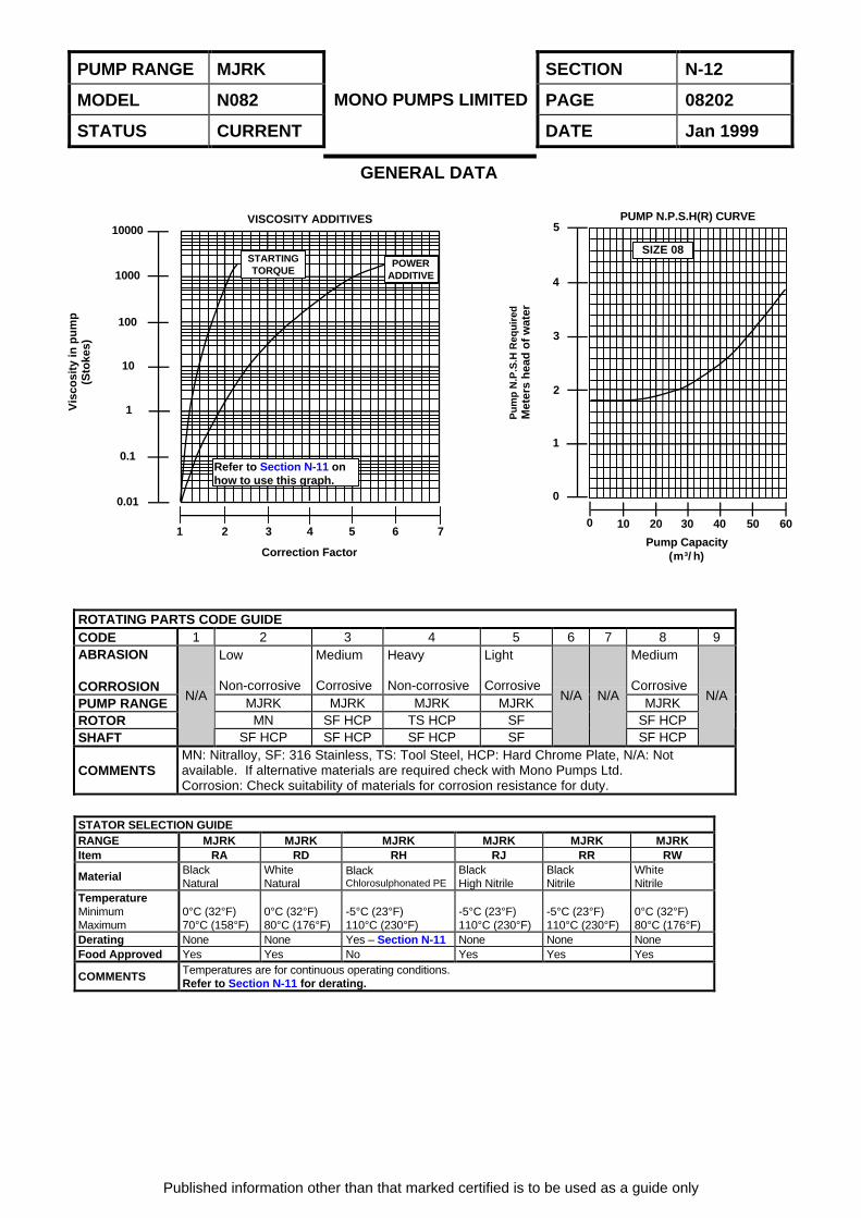
GENERAL DATA
ROTATING PARTS CODE GUIDECODE 1 2 3 4 5 6 7 8 9ABRASION
CORROSION
Low
Non-corrosive
Medium
Corrosive
Heavy
Non-corrosive
Light
Corrosive
Medium
CorrosivePUMP RANGE MJRK MJRK MJRK MJRK MJRKROTOR MN SF HCP TS HCP SF SF HCPSHAFT
N/A
SF HCP SF HCP SF HCP SF
N/A N/A
SF HCP
N/A
COMMENTSMN: Nitralloy, SF: 316 Stainless, TS: Tool Steel, HCP: Hard Chrome Plate, N/A: Notavailable. If alternative materials are required check with Mono Pumps Ltd.Corrosion: Check suitability of materials for corrosion resistance for duty.
STATOR SELECTION GUIDERANGE MJRK MJRK MJRK MJRK MJRK MJRKItem RA RD RH RJ RR RW
Material BlackNatural
WhiteNatural
BlackChlorosulphonated PE
BlackHigh Nitrile
BlackNitrile
WhiteNitrile
TemperatureMinimumMaximum
0°C (32°F)70°C (158°F)
0°C (32°F)80°C (176°F)
-5°C (23°F)110°C (230°F)
-5°C (23°F)110°C (230°F)
-5°C (23°F)110°C (230°F)
0°C (32°F)80°C (176°F)
Derating None None Yes – Section N-11 None None NoneFood Approved Yes Yes No Yes Yes Yes
COMMENTS Temperatures are for continuous operating conditions.Refer to Section N-11 for derating.
Refer to Section N-11 onhow to use this graph.
STARTINGTORQUE
POWERADDITIVE
1 2 3 4 5 6 7
0.01
0.1
1
10
100
1000
10000VISCOSITY ADDITIVES PUMP N.P.S.H(R) CURVE
0 10 20 30 40 50 60
0
1
2
3
4
5
SIZE 08
Pump Capacity(m³/h)
Pu
mp
N.P
.S.H
Req
uir
edM
eter
s h
ead
of
wat
er
Vis
cosi
ty in
pu
mp
(Sto
kes)
Correction Factor
MONO PUMPS LIMITED
RANGE(S) MJRK
MODEL N101
MAXIMUM CAPACITY 96 m³/h
MAXIMUM PRESSURE 6 Bar
MAXIMUM SPEED 400 rpm
PUMP RANGE MJRK SECTION N-12
MODEL N101 PAGE 10101
STATUS CURRENT
MONO PUMPS LIMITED
DATE Jan 1999
MK0 ROTORSELECTION
MK0 rotor is only to be used when viscosity is < 200cst andPressure is > 2 bar/stage OR > 3m suction lift.
SLIPCORRECTION
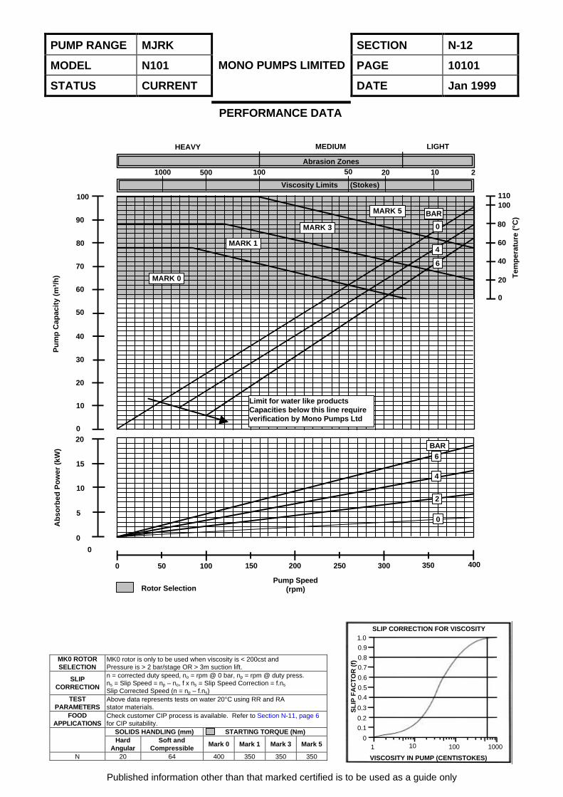
n = corrected duty speed, no = rpm @ 0 bar, np = rpm @ duty press.ns = Slip Speed = np – no, f x ns = Slip Speed Correction = f.ns
Slip Corrected Speed (n = np – f.ns)TEST
PARAMETERSAbove data represents tests on water 20°C using RR and RAstator materials.
FOODAPPLICATIONS
Check customer CIP process is available. Refer to Section N-11, page 6for CIP suitability.
SOLIDS HANDLING (mm) STARTING TORQUE (Nm)Hard
AngularSoft and
CompressibleMark 0 Mark 1 Mark 3 Mark 5
N 20 64 400 350 350 350
Published information other than that marked certified is to be used as a guide only
PERFORMANCE DATA
SLIP CORRECTION FOR VISCOSITY1.0
0.9
0.8
0.7
0.6
0.5
0.4
0.3
0.2
0.1
0
VISCOSITY IN PUMP (CENTISTOKES)
SL
IP F
AC
TO
R (
f)
1 10 100 1000
HEAVY MEDIUM LIGHT
Abrasion Zones
Viscosity Limits (Stokes)
1000 500 100 50 20 10 2
110100
80
60
40
20
0
Tem
per
atu
re (
°C)
Rotor SelectionPump Speed
(rpm)
0 50 100 150 200 250 300 350 400
0
0
5
10
15
200
10
20
30
40
50
60
70
80
90
100
Ab
sorb
ed P
ow
er (
kW)
Pu
mp
Cap
acit
y (m
³/h
)
BAR6
4
2
0
MARK 0
MARK 1
MARK 3
MARK 5 BAR
0
4
6
Limit for water like productsCapacities below this line requireverification by Mono Pumps Ltd
PUMP RANGE MJRK SECTION N-12
MODEL N101 PAGE 10102
STATUS CURRENT
MONO PUMPS LIMITED
DATE Jan 1999
Published information other than that marked certified is to be used as a guide only
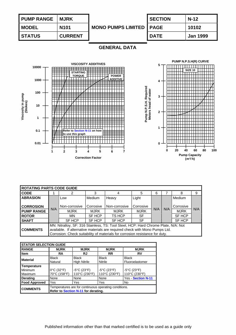
GENERAL DATA
ROTATING PARTS CODE GUIDECODE 1 2 3 4 5 6 7 8 9ABRASION
CORROSION
Low
Non-corrosive
Medium
Corrosive
Heavy
Non-corrosive
Light
Corrosive
Medium
CorrosivePUMP RANGE MJRK MJRK MJRK MJRK MJRKROTOR MN SF HCP TS HCP SF SF HCPSHAFT
N/A
SF HCP SF HCP SF HCP SF
N/A N/A
SF HCP
N/A
COMMENTSMN: Nitralloy, SF: 316 Stainless, TS: Tool Steel, HCP: Hard Chrome Plate, N/A: Notavailable. If alternative materials are required check with Mono Pumps Ltd.Corrosion: Check suitability of materials for corrosion resistance for duty.
STATOR SELECTION GUIDERANGE MJRK MJRK MJRK MJRKItem RA RJ RR RV
Material BlackNatural
BlackHigh Nitrile
BlackNitrile
BlackFluoroelastomer
TemperatureMinimumMaximum
0°C (32°F)70°C (158°F)
-5°C (23°F)110°C (230°F)
-5°C (23°F)110°C (230°F)
-5°C (23°F)110°C (230°F)
Derating None None None Yes - Section N-11Food Approved Yes Yes Yes No
COMMENTS Temperatures are for continuous operating conditions.Refer to Section N-11 for derating.
SIZE 10
0 20 40 60 80 100
0
1
2
3
4
5
1 2 3 4 5 6 7
0.01
0.1
1
10
100
1000
10000VISCOSITY ADDITIVES
PUMP N.P.S.H(R) CURVE
Pump Capacity(m³/h)Correction Factor
Refer to Section N-11 on howto use this graph
STARTINGTORQUE POWER
ADDITIVE
Pu
mp
N.P
.S.H
. Req
uir
edM
eter
s h
ead
of
wat
er
Vis
cosi
ty in
pu
mp
(Sto
kes)


![Thermomechanical Analysis [TMA] [NETZSCH]](https://img.pdfslide.us/doc/110x75/55cf940b550346f57b9f3bd8/thermomechanical-analysis-tma-netzsch.jpg)