Embed Size (px)
Citation preview
■ProtectandControlAnyKindofCapacitorBankApply to grounded and ungrounded, single- and double-wye capacitor banks.
■ProvideFlexibleMultibankProtectionandControlApply sensitive capacitor failure detection with application-based settings that provide voltage and current unbalance elements. Select from voltage, power factor, VAR, or time-of-day/day-of-week control schemes. Prevent equipment damage for up to three capacitor banks using control instability (hunting) detection.
■SimplifySettingsCalculationsAutomatically perform calculations for application-based settings using IEEE C37.99-based settings assistant software.
■SaveTimeIdentifyingFaultsFind faulty capacitor units using advanced faulted phase and section identification logic.
■ImprovePowerSystemReliabilityandStabilityWithBuilt-InSynchrophasorMeasurementSystemObtain real-time measurements of electrical quantities. Provide local control based on wide-area measurements.
Making Electric Power Safer, More Reliable, and More Economical ®
One Relay for Comprehensive Protection, Automation, and Control of All Your Capacitor Banks
SEL-487V Capacitor Protection and Control System
Features and Benefits
Grounded or Ungrounded
Grounded cap bank with low-voltage tap.
Double-wye grounded or ungrounded cap
bank.
Ungrounded cap bank with neutral-voltage
sensing.
Provided by N
ortheast Pow
er System
s, Inc. w
ww
.nepsi.com
2
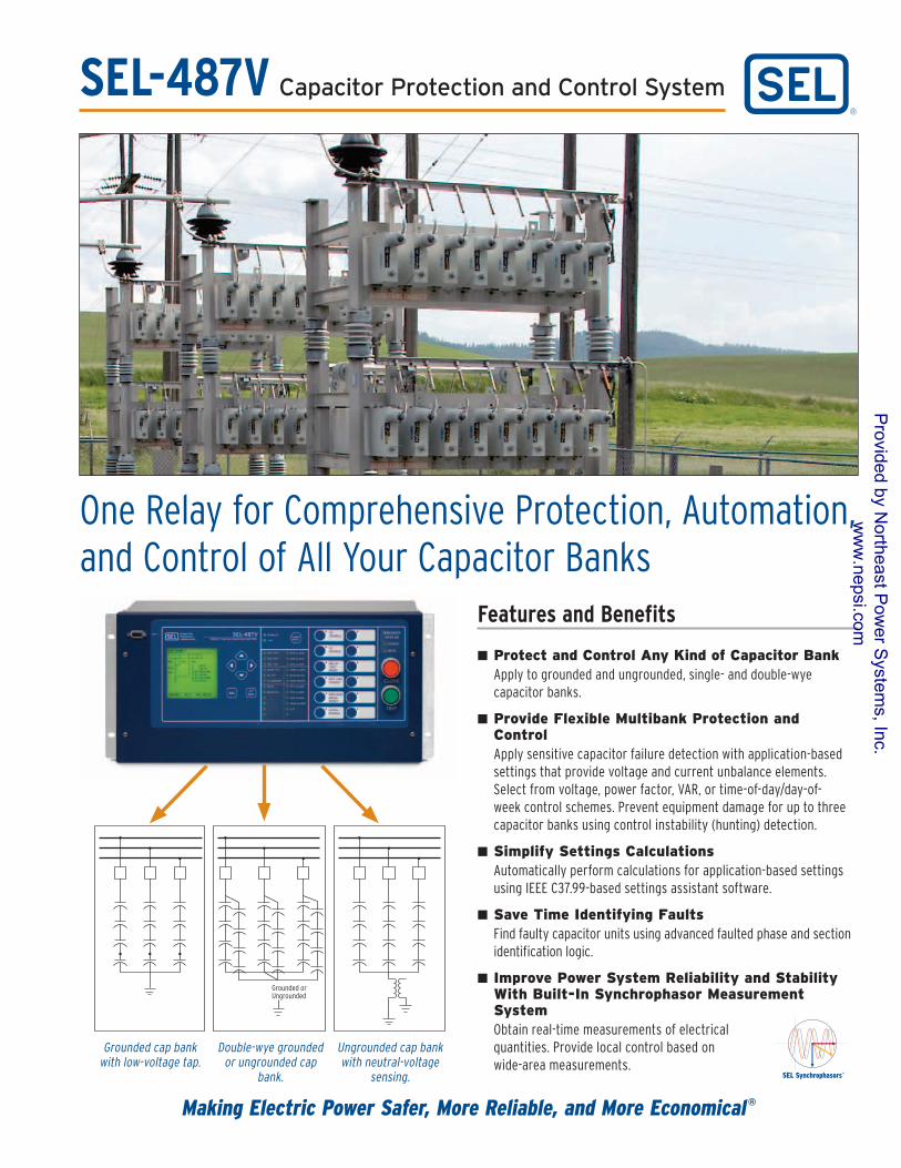
High-Performance Features
Worldwide, ten-year product warranty and —40° to +85°C operating temperature range are the best in the industry.
Easy-to-use keypad simplifies navigation and set-point adjustment.
Detailed, programmable target LEDs, with user-configurable labels, give fast and simple information to assist dispatchers and line crews in rapidly restoring power.
Select your own system bay configuration, and control as many as two breakers and five disconnect switches using the built-in mimic diagrams that include up to six programmable analog quantities for readouts.
Easily visualize preferred analog quantities and control breakers through the front- panel mimic display.
Programmable operator pushbuttons and configurable labels provide local switches to replace traditional panel switches.
Auxiliary trip and close buttons are electrically separate from the relay, allowing breaker control even when the relay is powered down.
Protection• Voltage Differential
• Current Unbalance
• Unbalance Compensation
• Over-/Undervoltage
• Over-/Underfrequency
• Breaker Failure
• Instantaneous Overcurrent
• Time-Overcurrent
• Expanded seLoGiC® Control Equations
• 8 kHz Oscillography
Automation• Ethernet Communications Protocols - FTP - Telnet - DNP3 LAN/WAN - IEC 61850 - IEEE C37.118 Synchrophasors
• Serial Communications Protocols - SEL Mirrored Bits
®
- SEL Fast Message - DNP3 - IEEE C37.118 Synchrophasors - IRIG-B
Control• Automatic Capacitor Bank Control - Voltage - VAR - Power Factor - Time-of-Day - Instability Detection• Local HMI Mimic Displays With Control and Metering
• Local and Remote Control Bits
• Programmable Automation and Protection Logic
• 24 Programmable Tricolor Target LEDs
• 12 Programmable Pushbuttons
3
3
33
32
27
27
50 51
59
59 87
81
SEL-487V
SEL-3530
SEL-2725
SEL-3021
SEL-3021 SEL-3021
SEL-487V
Provided by N
ortheast Pow
er System
s, Inc. w
ww
.nepsi.com
3
FindFaultsFasterReduce the time needed to identify faulted capacitor bank units with the faulted phase and section identification logic in the SEL-487V. This logic provides discrete indications for the phase and section of the faulted capacitor units. For voltage differential applications, the phase angle of the differential voltage determines the faulted phase and the sign of the differential voltage determines whether the fault is above or below the tap. For current unbalance applications, the phase angle of the unbalanced current determines the phase and bank where the fault is located.
Faulted-Phase Identification Protection
MinimizeSetupCostsandCommissioningTimeWithApplication-BasedSettings
Settings
EliminatetheNeedforaSeparateCapacitorController—ChoosetheOptionalSEL-487VControlFeature
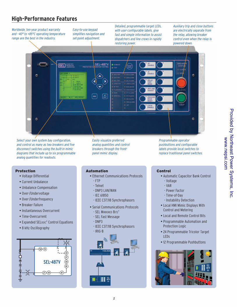
Obtain full control of your capacitor banks without the additional time, wiring, and installation of an additional device. Maintain system voltage, VAR, or power factor (PF) levels with deadband control functions, which include auto and manual as well as local and remote control capabilities. Apply control instability detection for alarm or blocking of control operations. Implement the time-of-day control feature to synchronize capacitor bank insertion with peak VAR demand periods for any weekday or weekend period.
Control
V MAG
V591
V271
P
Q
HPF[n]
LPF[n]
High PF
Low PF
P
Q
HVAR
HVAR
LVAR
LVARFigure 1. Voltage Control Deadband Characteristics
Figure 3. Power Factor Deadband Control Characteristics
Figure 2. VAR Deadband Control Characteristics
The SEL-487V saves time by automatically providing the recommended capacitor bank primary protection elements based upon capacitor bank nameplate and configuration settings. The relay only displays applicable protection elements (differential voltage, differential neutral voltage, neutral-current unbalance, and phase current unbalance protection) for easy setup.
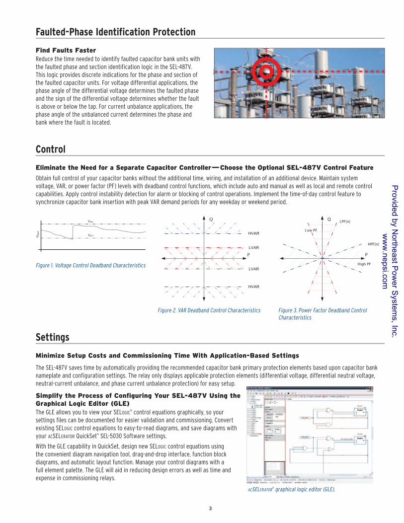
SimplifytheProcessofConfiguringYourSEL-487VUsingtheGraphicalLogicEditor(GLE)The GLE allows you to view your seLoGiC
® control equations graphically, so your settings files can be documented for easier validation and commissioning. Convert existing SELoGiC control equations to easy-to-read diagrams, and save diagrams with your ACseLerAtor QuickSet® SEL-5030 Software settings.
With the GLE capability in QuickSet, design new SELoGiC control equations using the convenient diagram navigation tool, drag-and-drop interface, function block diagrams, and automatic layout function. Manage your control diagrams with a full element palette. The GLE will aid in reducing design errors as well as time and expense in commissioning relays.
ACseLerAtor® graphical logic editor (GLE).
Provided by N
ortheast Pow
er System
s, Inc. w
ww
.nepsi.com
4
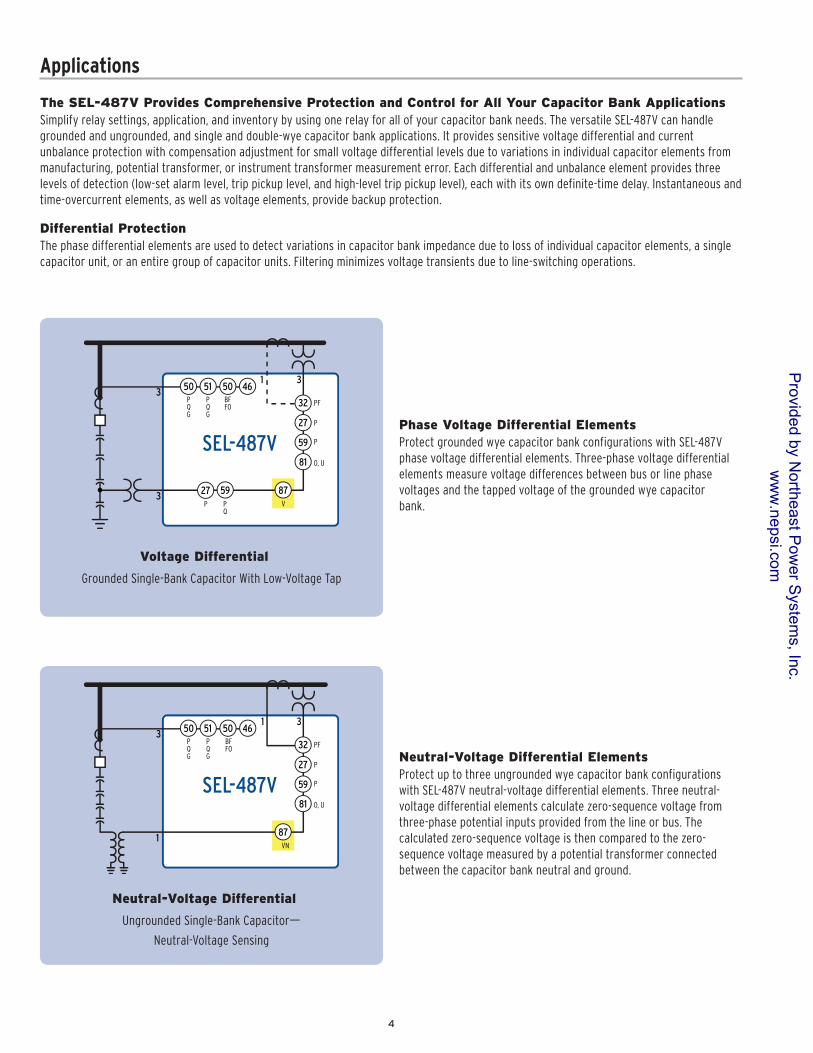
Neutral-VoltageDifferentialElementsProtect up to three ungrounded wye capacitor bank configurations with SEL-487V neutral-voltage differential elements. Three neutral-voltage differential elements calculate zero-sequence voltage from three-phase potential inputs provided from the line or bus. The calculated zero-sequence voltage is then compared to the zero-sequence voltage measured by a potential transformer connected between the capacitor bank neutral and ground.
TheSEL-487VProvidesComprehensiveProtectionandControlforAllYourCapacitorBankApplicationsSimplify relay settings, application, and inventory by using one relay for all of your capacitor bank needs. The versatile SEL-487V can handle grounded and ungrounded, and single and double-wye capacitor bank applications. It provides sensitive voltage differential and current unbalance protection with compensation adjustment for small voltage differential levels due to variations in individual capacitor elements from manufacturing, potential transformer, or instrument transformer measurement error. Each differential and unbalance element provides three levels of detection (low-set alarm level, trip pickup level, and high-level trip pickup level), each with its own definite-time delay. Instantaneous and time-overcurrent elements, as well as voltage elements, provide backup protection.
Applications
3
3
31
32
27
27
59
59
81
SEL-487V
50P Q G
P Q
P
P
P
PF
87V
O, U
51P Q G
4650BFFO
VoltageDifferential
Grounded Single-Bank Capacitor With Low-Voltage Tap
3
1
31
32
27
59
87
81
SEL-487V
50P Q G
P
P
PF
VN
O, U
51P Q G
4650BFFO
Neutral-VoltageDifferential
Ungrounded Single-Bank Capacitor—
Neutral-Voltage Sensing
PhaseVoltageDifferentialElementsProtect grounded wye capacitor bank configurations with SEL-487V phase voltage differential elements. Three-phase voltage differential elements measure voltage differences between bus or line phase voltages and the tapped voltage of the grounded wye capacitor bank.
DifferentialProtectionThe phase differential elements are used to detect variations in capacitor bank impedance due to loss of individual capacitor elements, a single capacitor unit, or an entire group of capacitor units. Filtering minimizes voltage transients due to line-switching operations.
Provided by N
ortheast Pow
er System
s, Inc. w
ww
.nepsi.com
5
3
3
3
27
59
81
SEL-487V
50P Q G
Q
P
O, U
51P Q G
4650BFFO
P
60
PhaseCurrentUnbalance
Double-Wye Grounded or Ungrounded Capacitor Bank
3
1
31
32
27
50 51
59
81
SEL-487V
P Q G
P
P
PF
N
O, U
P Q G
50 46BFFO
60
Neutral-CurrentUnbalance
Double-Wye Grounded or Ungrounded Capacitor Bank
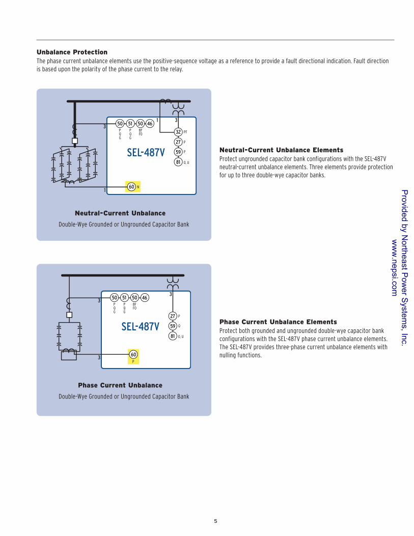
Neutral-CurrentUnbalanceElementsProtect ungrounded capacitor bank configurations with the SEL-487V neutral-current unbalance elements. Three elements provide protection for up to three double-wye capacitor banks.
PhaseCurrentUnbalanceElementsProtect both grounded and ungrounded double-wye capacitor bank configurations with the SEL-487V phase current unbalance elements. The SEL-487V provides three-phase current unbalance elements with nulling functions.
UnbalanceProtectionThe phase current unbalance elements use the positive-sequence voltage as a reference to provide a fault directional indication. Fault direction is based upon the polarity of the phase current to the relay.
Provided by N
ortheast Pow
er System
s, Inc. w
ww
.nepsi.com
6
FrequencyElementsThe SEL-487V provides six frequency elements, driven from either of the two terminal voltage inputs. Any of the six elements may be configured for over- or underfrequency. Each frequency element provides a pickup time delay setting. The frequency elements are supervised by a programmable undervoltage element. The undervoltage element can be set to monitor either of the two potential inputs and will block when the selected voltage input falls below a programmable undervoltage supervision threshold.
CurrentUnbalanceThe SEL-487V uses the average terminal current on one of the current terminals to calculate the percentage difference between the individual phase current and the terminal average current. If the percentage difference is greater than the set pickup value, the phase unbalance element is asserted. Terminal unbalance output is supervised using current fault detectors and the open-phase detection logic.
OvercurrentElementsThe SEL-487V calculates phase, negative-, and zero-sequence currents and offers three levels of overcurrent protection. Torque control is provided for each element.
The SEL-487V also includes ten selectable operating quantity inverse-time overcurrent elements.
The time-overcurrent curves have two reset characteristic choices for each time-overcurrent element. One choice resets the elements if current drops below pickup for one cycle. The other choice emulates the reset characteristic of an electromechanical induction disc relay.
VoltageElementsThe SEL-487V provides six independent over- and undervoltage elements with two pickup levels, the first pickup level having a definite-time delay. Choose from a wide range of fundamental and rms operating quantities for the two terminal voltage inputs.
Additional Protection Elements
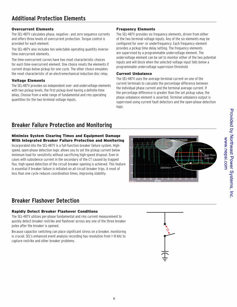
MinimizeSystemClearingTimesandEquipmentDamageWithIntegratedBreakerFailureProtectionandMonitoringIncorporated into the SEL-487V is a full-function breaker failure system. High-speed, open-phase detection logic allows you to set the pickup current below minimum load for sensitivity without sacrificing high-speed dropout. Even in cases with subsidence current in the secondary of the CT caused by trapped flux, high-speed detection of the circuit breaker opening is achieved. This feature is essential if breaker failure is initiated on all circuit breaker trips. A reset of less than one cycle reduces coordination times, improving stability.
Breaker Failure Protection and Monitoring
Subsidence
Open-PhaseDetection
RapidlyDetectBreakerFlashoverConditionsThe SEL-487V utilizes per-phase fundamental and rms current measurement to quickly detect breaker restrike and flashover across any one of the three breaker poles after the breaker is opened.
Because capacitor switching can place significant stress on a breaker, monitoring is crucial. SEL’s enhanced event analysis recording has resolution from 1—8 kHz to capture restrike and other breaker problems.
Breaker Flashover Detection
Provided by N
ortheast Pow
er System
s, Inc. w
ww
.nepsi.com
7
MakeSubstationIntegrationandAutomationSimpleWithEthernetCommunicationsIEC 61850 Ethernet-based communications provide interoperability between intelligent devices within the substation. Logical nodes using IEC 61850 allow standardized interconnection of intelligent devices from different manufacturers for monitoring and control of the substation. Reduce wiring between various manufacturers’ devices and simplify operating logic with IEC 61850. Eliminate system RTUs by streaming monitoring and control information from the intelligent devices directly to remote SCADA client devices using DNP3 LAN/WAN. Apply Telnet to access relay settings as well as metering and event reports remotely using the ASCII interface. Transfer settings files to and from the relay via the high-speed Ethernet port using FTP.
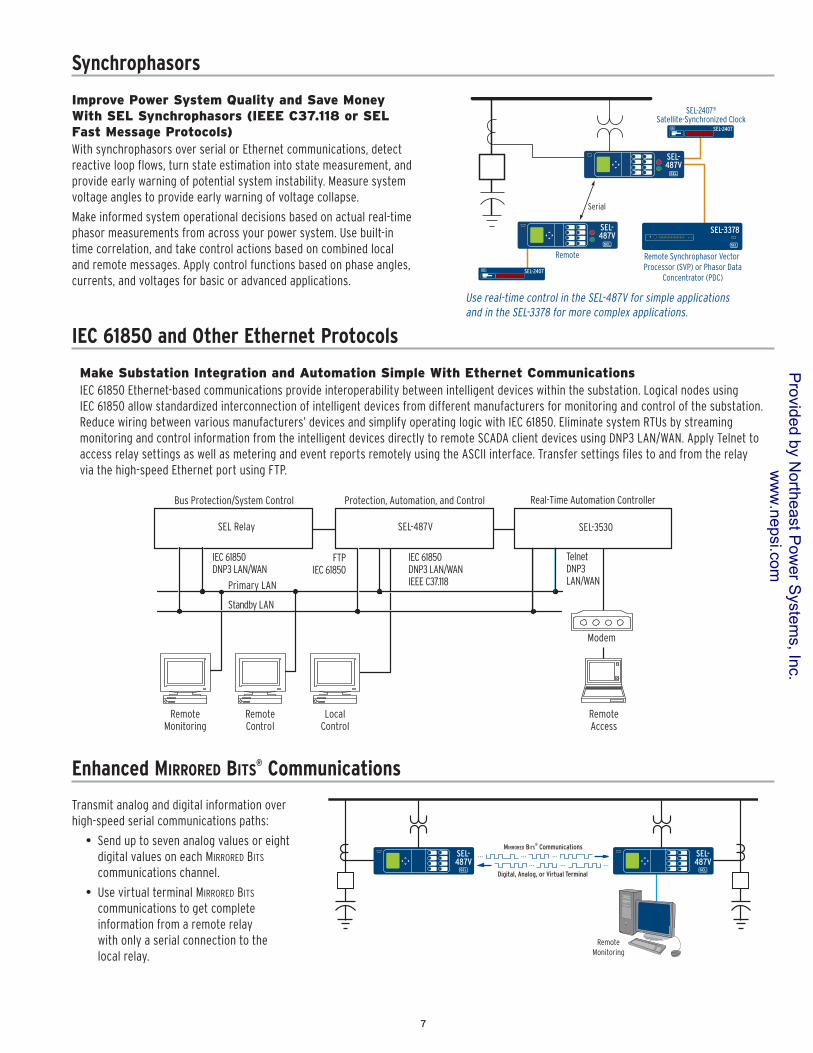
ImprovePowerSystemQualityandSaveMoneyWithSELSynchrophasors(IEEEC37.118orSELFastMessageProtocols)With synchrophasors over serial or Ethernet communications, detect reactive loop flows, turn state estimation into state measurement, and provide early warning of potential system instability. Measure system voltage angles to provide early warning of voltage collapse.
Make informed system operational decisions based on actual real-time phasor measurements from across your power system. Use built-in time correlation, and take control actions based on combined local and remote messages. Apply control functions based on phase angles, currents, and voltages for basic or advanced applications.
IEC 61850 and Other Ethernet Protocols
Synchrophasors
SEL-487V
SEL-487V
SEL-3378
Serial
Remote Synchrophasor Vector Processor (SVP) or Phasor Data
Concentrator (PDC)
Remote
SEL-2407
SEL-2407
SEL-2407®
Satellite-Synchronized Clock
Use real-time control in the SEL-487V for simple applications and in the SEL-3378 for more complex applications.
Protection, Automation, and Control
Standby LAN
Primary LAN
Modem
RemoteAccess
Bus Protection/System Control
RemoteMonitoring
RemoteControl
LocalControl
Real-Time Automation Controller
SEL-3530SEL-487VSEL Relay
TelnetDNP3LAN/WAN
FTPIEC 61850
IEC 61850DNP3 LAN/WAN
IEC 61850DNP3 LAN/WANIEEE C37.118
Transmit analog and digital information over high-speed serial communications paths:
• Send up to seven analog values or eight digital values on each Mirrored Bits communications channel.
• Use virtual terminal Mirrored Bits communications to get complete information from a remote relay with only a serial connection to the local relay.
Enhanced Mirrored Bits® Communications
RemoteMonitoring
. . . . . . . . .
. . . . . . . . .
MIRRORED BITS® Communications
SEL-487V
Digital, Analog, or Virtual Terminal
SEL-487V
Provided by N
ortheast Pow
er System
s, Inc. w
ww
.nepsi.com
PowerSupply
48/125 Vdc or 120 Vac 38—140 Vdc or 85—140 Vac (30—120 Hz)
125/250 Vdc or 120/230 Vac 85—300 Vdc or 85—264 Vac (30—120 Hz)
DC Burden <35 W
Typical Power Requirement 17.75 W @ 25°C
EthernetCommunicationsOptionsProvides IEC 61850, DNP3 LAN/WAN, FTP, and Telnet protocolsChoose two media options from the following list:
10/100BASE-T Twisted-Pair Network
100BASE-FX Fiber-Optic Network
FrequencyandPhaseRotation60/50 Hz system frequency and ABC/ACB phase rotation are user-settable
OperatingTemperature—40° to +85°C (—40° to +185°F)
Note: LCD contrast impaired for temperatures below —20° and above +70°C
Humidity5% to 95% without condensation
Weight(maximum)4U Rack Mount 9.8 kg (21.5 lbs)
5U Rack Mount 11.6 kg (25.5 lbs)
ACCurrentInputs(6total)
1 A or 5 A Inom (specify on order); 3 x Inom continuous; 100 x Inom one-second thermal rating; linear to 20 x Inom symmetrical
Burden 0.27 VA @ Inom for Inom = 5 A; 0.13 VA @ Inom for Inom = 1 A
ACVoltageInputs(6total)
300 VL-N continuous (connect any voltage up to 300 Vac) 600 Vac for 10 seconds
Burden 0.03 VA @ 67 V; 0.06 VA @ 120 V; 0.8 VA @ 300 V
OutputContactRatings(standardmodel)
30 A make per IEEE C37.90-1989 paragraph 6.7.2; 6 A continuous carry; MOV protected
Optional high-speed and high-current interrupting (10 A @ L/R = 40 ms) contacts available
SerialCommunicationsPorts
Three rear-panel and one front-panel EIA-232 serial ports
SEL ASCII Commands, SEL Mirrored Bits, SEL Fast Messages, DNP3
Serial Data Speed 300—57600 bps
ProcessingSpecifications
AC Voltage and Current Inputs: 8000 samples per second, 3 dB low-pass analog filter cut-off frequency of 3000 Hz
Digital Filtering: Full-cycle and two-cycle cosine filters, after low-pass analog and digital filtering
Primary Protection and Control Processing: 8 times per power system cycle
Synchrophasors—IEEEC37.118Standard
1—50 messages per second (50 Hz system)
1—60 messages per second (60 Hz system)
Pullman, Washington USATel: +1.509.332.1890 • Fax: +1.509.332.7990 • www.selinc.com • [email protected]
© 2009—2010 by Schweitzer Engineering Laboratories, Inc. PF00207 • 20101115
General Specifications
SEL-487V Capacitor Protection and Control System
Provided by N
ortheast Pow
er System
s, Inc. w
ww
.nepsi.com