Embed Size (px)
Citation preview

Seismometer Calibration Page 1
Sponsored by
www.iris.edu www.OregonShakes.com
SeismometerCalibration &Tune-Up Kit
January 2010Rev 2.0
We hope you find the Seismometer Calibration & Tune-Up Kit helpful and welcome anycomments and suggestions regarding this documentation. Please email
[email protected] to provide your feedback. Thanks!

Seismometer Calibration Page 2
Seismometer Calibration& Tune-Up Kit
September 2009Rev 1.1
INTRODUCTION
So, you have just received your seismometer and have performed the initial setup. Youare now ready for the important set of tuning and calibrating your seismometer. Manyof the calibration steps are performed to insure the health of your seismometer. Someof the steps are performed “just in case”.
TUNE-UP: We are all familiar with tune-ups. Most of us take our car in regularly foran oil change and a tune-up to keep it running at peak performance. Your seismometeris no different! You want to capture all the earthquakes that you can. And, you’ll havethe best success if your seismometer is running properly
CALIBRATION: Have you ever been to the doctor and he or she says “let’s get an x-ray so we have a good baseline”. What the doctor means is that if you have trouble inthe future, he or she can repeat the test and compare it to the “baseline” test. Yourseismometer is no different. You want to perform the baseline tests so that if you haveproblems later it can be used to help troubleshoot your seismometer.
Please note that even if you don’t have the seismometer calibration & tune-up kit, mostof the contents are simple household items. So don’t let that stop you from using thisguide.
So, let’s get started!

Seismometer Calibration Page 3
TABLE OF CONTENTS
1. What’s in the kit
2. TUNE-UP PROCEDURESa. Knife edge tune-upb. Set correct spacing on the magnetic damperc. Leveling your seismometerd. Damping calibratione. Align the Magnet/Coilf. Filing a slot in the acrylic coverg. Checking wires to the “Black Box”h. Setting the zero leveli. Adjusting the gain based on the noise level
3. CALIBRATION PROCEDURESa. Washer testb. Checking the system’s free periodc. Noise Testd. Inductance Teste. Lift Test
4. Who to contact for more help
Seismometer Calibration Page 4
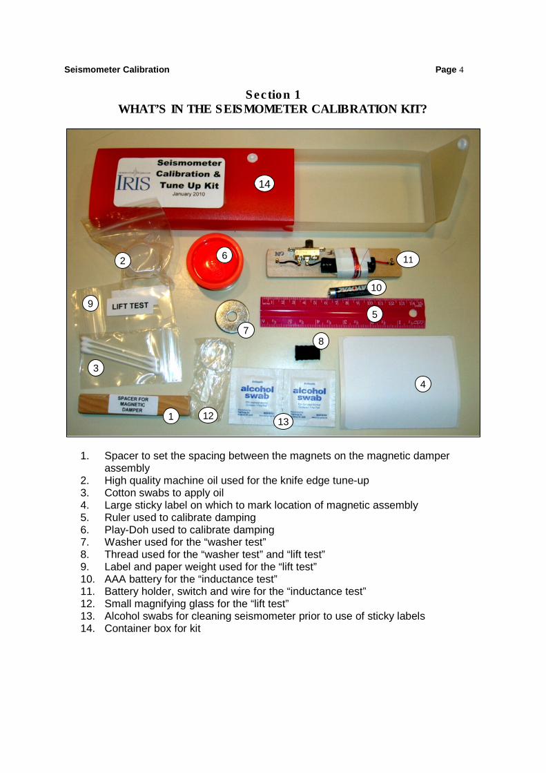
Section 1WHAT’S IN THE SEISMOMETER CALIBRATION KIT?
1. Spacer to set the spacing between the magnets on the magnetic damperassembly
2. High quality machine oil used for the knife edge tune-up3. Cotton swabs to apply oil4. Large sticky label on which to mark location of magnetic assembly5. Ruler used to calibrate damping6. Play-Doh used to calibrate damping7. Washer used for the “washer test”8. Thread used for the “washer test” and “lift test”9. Label and paper weight used for the “lift test”10. AAA battery for the “inductance test”11. Battery holder, switch and wire for the “inductance test”12. Small magnifying glass for the “lift test”13. Alcohol swabs for cleaning seismometer prior to use of sticky labels14. Container box for kit
1
2
34
5
6
78
910
11
12 13
14

Seismometer Calibration Page 5Section 2a
KNIFE EDGE TUNE-UP
On the AS-1, the horizontal boom has a knife edge which fits into a groove on thevertical support. The worst enemy for your seismometer is noise and the knife edgecan often be the culprit. The ideal pivot point is friction free. The knife edge will alwayscreate a very low amount of noise. But the noise can be quite high if the knife edgegets nicked or is rough. So it is a good idea to occasionally inspect your knife edge,especially after you move it to a new location.
WARNING: The knife edge is sharp so be very careful!
First, remove the boom from theseismometer and detach the spring.
Inspect the knife edge. Does it have anyobvious nicks or rough spots? If not, skip
the sharpening step below. Otherwiseproceed to the next step.
The best way to sharpen the knife edge iswith a sharpening stone such as the oneon the right because the knife edge mustbe very flat and not have “waves”. Youmay have a friend or neighbor such a
stone.
After oiling the stone, hold the boom at about a 20 degree angle and press on the stone whilepulling in ONE direction only (towards the end with the magnet). Be sure to sharpen the sidewith the beveled edge. Once sharpened wipe the blade across the corner edge of a piece of
hardwood. This removes the “fuzz” or any free material without damaging the edge.Carefully wipe the knife edge with a clean dry cloth by starting at the boom and moving over
the edge in only one direction

Seismometer Calibration Page 6
Now remove the lid from the vial of highquality machine oil. Dip a clean cotton
swab into the oil.
Wipe across the knife edge on both sides.You don’t need much oil. A drop or two issufficient.
Next, with the other end of the cottonswab, dip into the oil and “scrub” the groveon the upright to remove any metal dust ordirt. Wipe dry with a clean dry cloth. You
are now ready to reassemble theseismometer!

Seismometer Calibration Page 7
Section 2bSET CORRECT SPACING ON THE MAGNETIC DAMPER
If you are using magnetic damping on your seismometer and not oil damping, you havea damper assembly consisting of a copper paddle (attached to the boom) and a quadarray of neodymium magnets on two steel plates which sits on the base. Setting thecorrect distance between the magnets is important for proper damping. But it is also asimple job to perform. Before you start, please read the safety information below.
SAFETY INFORMATION
These magnets are extremely strong, and must be handled with care to avoid personalinjury and damage to the magnets. Fingers and other body parts can get severelypinched between two attracting magnets. Neodymium magnets are brittle shatter ifallowed to slam together. Eye protection should be worn when handling these magnets,because shattering magnets can launch pieces at great speeds.
The strong magnetic fields of neodymium magnets can also damage magnetic mediasuch as floppy disks, credit cards, magnetic I.D. cards, cassette tapes, video tapes orother such devices. They can also damage televisions, VCRs, computer monitors andother CRT displays. Never place neodymium magnets near electronic appliances.
Now that we have the safety issues behind us, let’s talk about how the device works.The copper paddle extending from the boom is moved between pairs of strongneodymium magnets. The movement of the copper paddle is perpendicular to themagnetic field. This induces “eddy currents” within the paddle which actually createinternal magnetic fields opposing the change. This “electrical resistance” within the
Seismometer Calibration Page 8copper paddle causes a dragging effect analogous to friction, which dissipates thekinetic energy of the paddle. The same technique is used in electromagnetic brakes inrailroad cars, brakes in roller coasters and to quickly stop the blades in power tools suchas circular saws.
This effect is insensitive to temperature (although at very high temperatures neodymiummagnets lose their strength). That is why it is preferable to oil damping. The propertiesof the oil damping change dramatically with temperature – not a good thing!
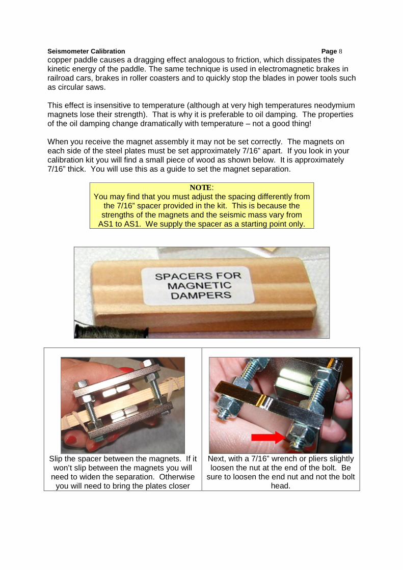
When you receive the magnet assembly it may not be set correctly. The magnets oneach side of the steel plates must be set approximately 7/16” apart. If you look in yourcalibration kit you will find a small piece of wood as shown below. It is approximately7/16” thick. You will use this as a guide to set the magnet separation.
NOTE:You may find that you must adjust the spacing differently from
the 7/16” spacer provided in the kit. This is because thestrengths of the magnets and the seismic mass vary from
AS1 to AS1. We supply the spacer as a starting point only.
Slip the spacer between the magnets. If itwon’t slip between the magnets you will
need to widen the separation. Otherwiseyou will need to bring the plates closer
Next, with a 7/16” wrench or pliers slightlyloosen the nut at the end of the bolt. Be
sure to loosen the end nut and not the bolthead.

Seismometer Calibration Page 9together.
Then loosen the nuts on the other side ofthe steel plate. You will adjust these nutsso that the steel plate will drop down to the
spacer
The plate should drop down so that themagnets just barely touch the spacer. It needs
to be loose enough so the spacer can easilybe slipped out of the magnetic assembly.
Finally finger tighten the outside nuts.Then with a wrench or pliers tighten the
nuts securely to hold the steel plate in thisposition.

Seismometer Calibration Page 10
Section 2cLEVELING YOUR SEISMOMETER
Make sure that your seismometer is properly leveled. Start by placing the small bubblelevel between the two thumbscrews near the vertical support of the seismometer.
Adjust the two screws until the bubble is centered in the level.
Now move the bubble level near the coil on the base. Adjust the single thumb screw tillthe bubble is centered in the level.

Seismometer Calibration Page 11
NOTE:Be sure that the magnet is NOT rubbing against the coil when
you level the boom!
Now place washers on the vertical bolt near the magnet end of the boom. Keep addingwashers until the boom is almost, but not quite, level. Then place the bubble level onthe boom and slide it on the boom till the bubble level shows it is level. Be sure toleave the bubble level on the seismometer.

Seismometer Calibration Page 12
Section 2dDAMPING CALIBRATION
Magnetic damping is preferable to oil damping because it is not affected bytemperature. When the oil in an oil damped system gets cold it can exceed criticaldamping and you may not record any earthquakes at all. In fact, the workingtemperature range for an oil damped seismometer is only about +/-5 degreesFahrenheit -- less than the room temperature variation between day and night. Onceset properly, a magnetically damped system will operate properly at all times and henceyou may record more earth quakes. The catch is that it must be properly set.
Before you perform the damping calibration, be sure that you set the correct spacingbetween the steel plates as described in the previous step. And, be sure that thedamping blade is aligned parallel to the boom. The blade should clear the lower bolt onthe damping magnet block by about 1/8".
First, clean the seismometer baseunderneath the damper paddle to remove
any oils and dirt. Let it dry completely
Then place the white sticky labelunderneath the paddle. It won’t stick
unless the base is clean and dry.
Seismometer Calibration Page 13
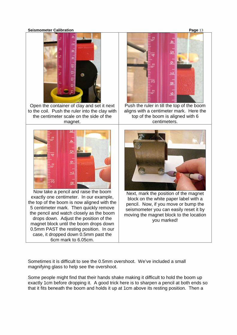
Open the container of clay and set it nextto the coil. Push the ruler into the clay with
the centimeter scale on the side of themagnet.
Push the ruler in till the top of the boomaligns with a centimeter mark. Here the
top of the boom is aligned with 6centimeters.
Now take a pencil and raise the boomexactly one centimeter. In our example,
the top of the boom is now aligned with the5 centimeter mark. Then quickly removethe pencil and watch closely as the boom
drops down. Adjust the position of themagnet block until the boom drops down0.5mm PAST the resting position. In ourcase, it dropped down 0.5mm past the
6cm mark to 6.05cm.
Next, mark the position of the magnetblock on the white paper label with a
pencil. Now, if you move or bump theseismometer you can easily reset it by
moving the magnet block to the locationyou marked!
Sometimes it is difficult to see the 0.5mm overshoot. We’ve included a smallmagnifying glass to help see the overshoot.
Some people might find that their hands shake making it difficult to hold the boom upexactly 1cm before dropping it. A good trick here is to sharpen a pencil at both ends sothat it fits beneath the boom and holds it up at 1cm above its resting position. Then a

Seismometer Calibration Page 14quick flick on the pencil will let the boom drop. There are many ways to do this sochoose the method that works best for you.

Seismometer Calibration Page 15
Section 2eALIGNING THE MAGNET/COIL
This is an easy step. The goal is to keep the magnet from rubbing against the coil. Youwant to make sure that the boom/magnet moves freely without friction from the coil. Bythe way, this is one of the most common errors and it is a sure way to miss thoseearthquakes that you wanted to record.
Be sure that the base and boom are properly leveled before you perform thealignment.
Now, move around the seismometer till you are looking at it end on. Observe to makesure that the following is correct:
• The red magnet must be aligned parallel to the boom• The coil needs to be aligned parallel to the boom• The red magnet needs to be centrally spaced over the coil
If the answer is yes to all three, you are good to go!
If the answer is no to the first two, loosen the bolts and align properly.
If the answer is no to the third and it is only slightly off, slide the boom back and forth atthe knife edge pivot point till it is aligned properly.
If the answer is no and it is off by more than 1/8th of an inch, look at the metal supportholding the coil. Is it perpendicular to the base? If not, VERY carefully bend it so that itis vertical. You don’t want to bend it too much or too often because the metal canfatigue and break. Once the coil support is vertical do the final adjustment as describedin the previous step.

Seismometer Calibration Page 16
Section 2fFILING A SLOT IN THE ACRYLIC COVER
It is important to minimize any air currents inside the cover over the seismometer. If thecover rests on the cable then air can seep in underneath the cover. It is best to file asmall round slot on the bottom of the cover where the cable can feed out to the “blackbox”. Use a round file to do this. A friend or neighbor may have a file such as this.
Now the cover will rest directly on the floor or tabletop and very little air can seep in.

Seismometer Calibration Page 17Section 2g
CHECKING WIRES TO THE “BLACK BOX”
One of the best ways to introduce noise into your system is by incorrectly feeding theseismometer wires into the “Black Box”. Here are two hints for you to make sure thisdoesn’t happen to you.
Hint #1
Make sure when you feed the wires intothe holes on the screw jacks. Yes, thisis obvious, but it is so easy to miss thehole. And, even if you miss the holeyou can still clamp it down with the
screw cap. But this can easily lead to aloose connection making it very difficult
to diagnose the problem.
Hint #2
If you feed too much wire through the holethey may touch each other leading to a shortin the connection. This can be intermittenttoo making it very difficult to diagnose.

Seismometer Calibration Page 18Section 2h
SETTING THE ZERO LEVEL
This is the step that strikes fear in even the boldest teacher! Setting the zero level isprobably the most difficult part of setting up an AS1 system. The knob on the AS1“black box” is VERY sensitive.
First make sure that the AmaSeis display show one hour of data per line.
Under the “Settings” tab in AmaSeis click “Set Zero Level”. Make sure that it is set to“2048”. This is because the “black box” has a 12 bit digital to analog converter and sothe numbers will range from 0 to 4096. By setting the “zero level” to 2048, AmaSeis willinterpret the input numbers from 0 to 2048 to be -2048 to 0 and the input numbers 2049to 4096 to be 1 to 2048.
Next click “Show Data Values” under the “Settings” tab. You will see the following:
When you turn the knob all the way to the left the data values will be pegged on eitherminus or plus 2048. As you turn the knob all the way to the right it will be pegged in theother direction.
Now slowly turn the knob as you watch the level. Once you get it to within about 100counts of zero (it will fluctuate above and below a few counts depending on the noiselevel) you should make slight adjustments by tapping the knob lightly with a pencil untilthe numbers bounce equally above and below zero.

Seismometer Calibration Page 19
Once it is adjusted it is helpful to put a piece of tape on the “Black Box” and place amark by the pointer on the black knob.
And to protect the setting on the black box we recommend that you cover the adjustingknob. One way is to cut off a 1” length of the cardboard tube on a paper towel roll.Place it over the knob and then tape it on the black box. Be careful not to change theadjustment while you are taping.

Seismometer Calibration Page 20
Section 2iADJUSTING THE GAIN BASED ON THE BACKGROUND NOISE
In the “Settings/Helicorder/Gain” set the helicorder display gain so that the backgroundnoise is quite clear as in the seismogram below.
The gain on the record below is too low. You might miss seeing earthquakes when it isset like this.
The gain may need to be reduced during storms and increased during quiet times socheck it often.
Below are seismograms from a seismograph located near the ocean. The one on theleft was from a relatively calm day and the one on the right was from a day when the
“surf was up” on the ocean. The gain should have been lowered on the stormy day andthe gain should have been raised on the calm day.
January 15, 2007January 8, 2007

Seismometer Calibration Page 21
In fact, we can correlate it to wave height using NOAA buoy data below.
January 2007 Wave Height
012345678
1/1/20
07
1/3/20
07
1/5/20
07
1/7/20
07
1/9/20
07
1/11/2
007
1/13/2
007
1/15/2
007
1/17/2
007
1/19/2
007
1/21/2
007
1/23/2
007
1/25/2
007
1/27/2
007
1/29/2
007
1/31/2
007
WVHT
Maximum Wave Height on January 8,
Minimum Wave Height on January 15,

Seismometer Calibration Page 22
Section 3aWASHER TEST
The washer test is the first test done after the seismometer is connected to the blackbox. Be sure to first perform the zero level adjustment using the AmaSeis software.
The washer test is the simplest of all the “post hook-up” tests and is helpful for a varietyof reasons. It can help to make sure that you have the polarity set correctly. Andshould you run into problems later on it is simple to repeat the procedure to see whatchanged (if any) have occurred. And, it can be used to help the IRIS support folksdiagnose any problems that may exist.
The first step is to tie one end of thethread around the washer included in
your calibration kit.
Then place the washer next to theacrylic cover next to the coil. Let the
seismometer “rest” for a few momentsand then yank away the washer.
You should see a waveform that lookssimilar to this. Highlight it with thecursor and then click the AmaSeis
plot icon . The calibration pulseshould go down, then up and thenreturn to zero. If the pull first goes UPswap the outside leads into the “BlackBox”. Do NOT change the centerground lead into the “Black Box”. Youwill likely see some level of
microseism noise on the pulse as well. Take a moment to note which way the magnetmoved and which way the seismogram trace moved when the washer was pulled away.
Save the calibration pulse as a SAC file for future reference.

Seismometer Calibration Page 23
When the ground moves down, the magnet will tend to remain fixed, which means itmoves up with respect to the coil.
Note that the overshoot during a washer calibration is primarily due to the electronicfilters in the AS-1 “black box”.
This overshoot will be much more than 1/20th of the first pulse, as it should be.
However, this test can reveal whether the system is properly damped. Look at thepulse below on the left. This is from a system that had too little damping. The pulse onthe right is from a properly damped system.

Seismometer Calibration Page 24
Section 3bCHECKING THE SYSTEM’S FREE PERIOD
First, pull the magnet carrier away from the copper damping vane.
Next, make sure the helicorder setting displays one hour per line and set the gain to 5.Gently tap the seismometer base. Undamped oscillations look like this.
Select one of the pulses and click the icon to display a single trace. The oscillationsshould continue for at least three minutes Save a file in SAC format showing the freeoscillation decay so that it can be compared with a similar test in the future to determineif the spring or hinge has changed.

Seismometer Calibration Page 25
Measure the time between two peaks or two troughs. This is the free or natural periodof the system. Here we measured 1.4 seconds.
1.4 sec

Seismometer Calibration Page 26Section 3c
ELECTRONIC NOISE TEST
Electronic noise is present in all electronic circuits. Believe it or not, the electronic noisepresent in the AS-1 “Black Box” can help us diagnose potential problems.
To perform this test, unplug the seismometer from the black box. Then remove theacrylic cover and place a weight on top of the boom so that the magnet is resting firmlyon the coil. This eliminates any signal created from the magnet/coil assembly. Belowwe used a stack of small wood pieces. Alternatively, you could unhook the spring andremove the boom entirely for this test.
Next, plug the seismometer back into the “Black Box”, connect to the computer. Andstart AmaSeis. The electronic noise when the boom is held fixed is just 3 counts peak-to-peak. Below is an example of what you should see.

Seismometer Calibration Page 27

Seismometer Calibration Page 28
Section 3dINDUCTANCE TEST
Occasionally there may be a problem with the coil on the seismometer. A bump or dropmight break one of the delicate wires causing an open circuit. Or it might chip thepolyester coating on the wires causing it to short. This is a great test to determine thehealth of your coil. And it is a lot easier to do than you might think!
Initial steps:• Disconnect your seismometer from the “Black Box”• Remove the cover from your seismometer• Remove the boom and set it aside so that the magnet is away from the coil.
Your kit comes with a simple device that will assist you in the inductance test. Carefullyunwind the 32 gauge magnet wire from the device and remove the paper. Be carefulnot to kink or break the magnet wire. Turn the switch to the “off” position and put theAAA battery into the battery holder.
With a scissors, scrape off thepolyester coating on one end of themagnet wire.* The color will changeslightly after scraping.
Wrap the scraped end of the magnetwire tightly around one of the posts on
the induction test device as shown.Make sure it is snug.

Seismometer Calibration Page 29
Feed the other end of the magnet wireunderneath the coil and twist tosecure. There should be ONE looparound the coil.
Scrape the coating off of the other endof the magnet wire* and secure it tothe other post.
You are now ready to connect the seismometer to the “Black Box”. You don’t need toreplace the cover or the boom on the seismometer. Turn on the “Show Data Values”.Wait a few moments till the signal settles on the AmaSeis screen. The data valuesshould be close to zero.
Turn the switch on the induction test device to the “ON” position. This “turns on” theelectrical current. As you watch the AmaSeis screen you will see a pulse go down andthen up again. Wait for a few seconds for the signal to settle around zero again. Thenturn the switch to the “OFF” position. This “turns off” the current. You should see apulse going UP on the AmaSeis screen. Wait a few seconds till the signal settles again.
Then with the cursor highlight both pulses and click the icon to plot a single trace. Itshould look like the screen capture below.

Seismometer Calibration Page 30
This calibration is independent of the AS1 spring and damping system.
Be sure to save this as a SAC file for future reference.
* Another way to remove the insulation from the ends of the magnet wire is to hold itbriefly under a cigarette lighter. Then use a fine emery board or wire wool to clean the
end.

Seismometer Calibration Page 31Section 3eLIFT TEST
The lift test is a relative calibration of the AS-1 seismograph and is performed using a“step function” method. A small mass is placed on the boom of the instrument which isquickly removed.
First, unplug the seismometer from the “Black Box”.
In your Calibration Kit look for the bag containing a small label and a small piece ofmanila folder cut to 1 cm by 2 cm. Lay the 6” ruler on the boom edge andapproximately 10 cm (100cm) from the vertical support place the white sticky label onthe boom off to one side as shown below. Don’t place it in the middle of the boombecause you might brush the spring when you lift the weight. Next, with a pencil mark aline exactly 10cm from the vertical support.
SAFETY NOTE:This test should NOT be done if you are using a glass cover.
It is extremely difficult to safely drill a hole into glass.
Now, replace the acrylic cover onto the seismometer. Look straight down and place amark on the acrylic cover exactly over the 10cm mark on the boom. Carefully drill a 1/8”hole through the plastic in this position. For those of you who have the “standard”acrylic cover it will be 14.5 cm from the end and 7.7 cm from the side.

Seismometer Calibration Page 32
Remove the small piece of manila folder from the bag and fold it in half. This is 0.0318grams in weight. Next, take a pencil and punch a small hole through the paper nearthe fold. Take the thread from the Calibration Kit, feed it through the hole and tie it in aknot.
Measure about a yard of thread and cut it off of the spool. Reaching from the INSIDE ofthe acrylic cover, feed the thread through the 1/8” hole.
Replace the acrylic cover over theseismometer. Lower the paper weightdown onto the boom where you placed themark at 10 cm. Don’t let the thread slipthrough the hole! Plug the seismometerback into the“Black Box”and startAmaSeis.Loosely holdthe threaddirectly above
the paper weight but don’t disturb the weight.
Let the noise level settle on the AmaSeis screen. Then,quickly lift the thread about an inch or two. You don’twant to lift it all the way to the top because you mightbrush the spring creating unwanted noise.

Seismometer Calibration Page 33
Wait for a few seconds after lifting the weight. Then highlight the pulse on the AmaSeisscreen and click the icon to plot an individual trace. Be sure to save your test in a SACfile.
Your pulse should have the following characteristics:• amplitude of first trough (negative) = -1420 +/- 150 counts• amplitude of first peak (positive) = 480 +/- 50 counts• time from beginning of calibration pulse to first zero crossing = 3.0 +/- 0.5
seconds
You can also check for correct polarity on your system. If the pulse first goes UPinstead of down, swap the outside leads going into the “Black Box”. Do NOT changethe center ground lead into the “Black Box”.
For more information see Larry Braile’s “relative calibration” information on his webpage at http://web.ics.purdue.edu/~braile/edumod/as1mag/as1mag1.htm.

Seismometer Calibration Page 34
Section 4WHO TO CONTACT FOR MORE HELP
A special email address has been created just so that you can contact us for furtherhelp in calibrating your seismometer. In fact, if you have any questions at all, feel freeto contact us at
In addition, we highly encourage you to check out the IRIS Seismographs in Schoolswebsite at www.iris.edu/hq/sis. Here you will find a wealth of information on a varietyof topics.
Under the “Community” tab check out the Discussion Forum. You can also post yourquestions here. If you have a question, you can be sure that other teachers havesimilar questions.
And, under the “Resources” tab check out the “FAQs” section (frequently askedquestions). Not only can you find answers to many of your questions, you will findvideo clips on the entire process of setting up your seismometer!
![The Great Invention: Seismoscope by Sissi Liu. The differences between a seismometer and a seismoscope. What is a seismoscope? [seismocope vs seismometer]](https://img.pdfslide.us/doc/110x75/56649de55503460f94addeb9/the-great-invention-seismoscope-by-sissi-liu-the-differences-between-a-seismometer.jpg)