Embed Size (px)
Citation preview
SEISMIC GEOTECHNICALSEISMIC GEOTECHNICAL HAZARDSHAZARDS
Liquefaction Inducedque act o duced

Learning Outcomesg
Be able to describe:Be able to describe: Types and impacts of liquefaction induced
h dhazards Methods for evaluating liquefaction hazards Methods for mitigating liquefiable sites.

LIQUEFACTION INDUCED HAZARDS

Liquefaction Hazardsq
Flow Slides Lateral Spreads Lateral Spreads Reduction in Foundation Bearing
C itCapacity Ground SettlementG ou d Sett e e t Increased Pressure on Retaining
W llWalls
Liquefaction-Induced Bearing Capacity Failures
1999 M 7.4 Kocaeli Earthquake, Turkey

Liquefaction-Induced Lateral Spread q pDamage
Lateral Spread Damage to Bridges and p g gWaterfront Retaining Walls
during the 1964 Niigata earthquake
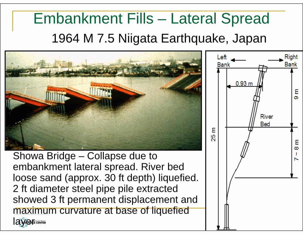
Embankment Fills – Lateral Spread1964 M 7.5 Niigata Earthquake, Japan
Showa Bridge – Collapse due to embankment lateral spread. River bed l d ( 30 f d h) li fi dloose sand (approx. 30 ft depth) liquefied.2 ft diameter steel pipe pile extracted showed 3 ft permanent displacement andshowed 3 ft permanent displacement and maximum curvature at base of liquefied layer
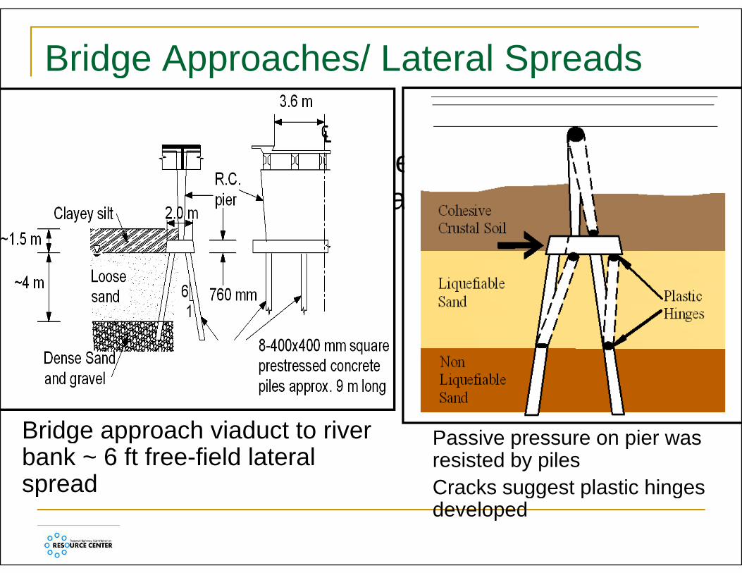
Bridge Approaches/ Lateral Spreadsg pp p
1987 M 6.3 Edgecumbe Earthquake, New Zealand
Bridge approach viaduct to riverBridge approach viaduct to river bank ~ 6 ft free-field lateral spread
Passive pressure on pier was resisted by piles Cracks suggest plastic hinges p gg p gdeveloped

Lateral Spreading: Impact on Foundations
1995 M 6.9 Hyogo ken Nambu Earthquake, Kobe, Japan
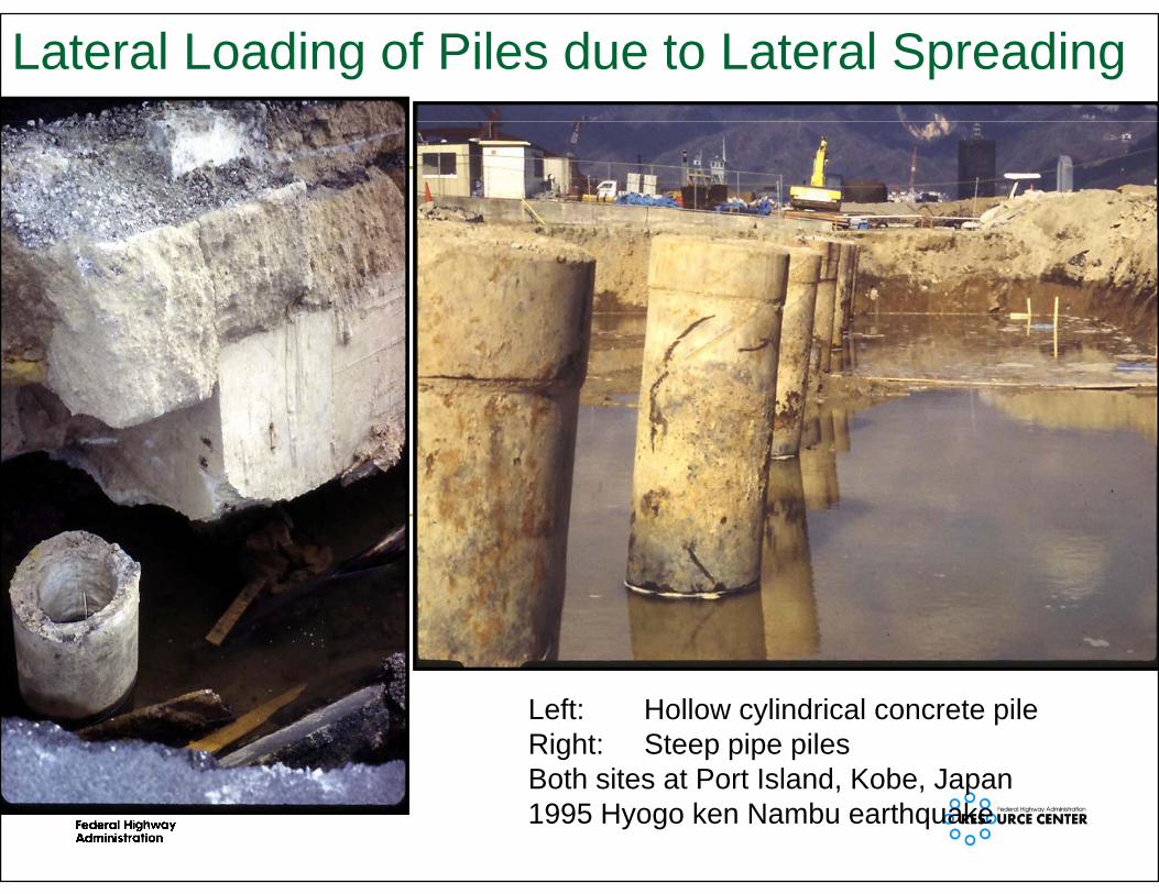
Lateral Loading of Piles due to Lateral Spreading
Left: Hollow cylindrical concrete pileRight: Steep pipe pilesB th it t P t I l d K b JBoth sites at Port Island, Kobe, Japan1995 Hyogo ken Nambu earthquake

Flow Slide: Sheffield Dam1925 M 6.8 Santa Barbara earthquake
Cross Section at Time of Failure

Sheffield Dam Flow Failure

Seismic Settlement Damage
1964 M 9.2 Alaska EarthquakeSettlement of approach fill 1989 M 6.9 Loma Prieta
E th kEarthquakeSettlement of approach fill

Seismic Settlement Damage
Port Island, Kobe, JapanPort Island, Kobe, Japan1995 M 6.9 Hyogo ken Nambu earthquake Bridge abutment fillBridge abutment fill
2001 M 7.6 Chi-Chi earthquake, Taiwan

EVALUATION OFEVALUATION OF POTENTIALLY LIQUEFIABLEPOTENTIALLY LIQUEFIABLE
SITES

Liquefaction: Definition & Consequencesq q
Liquefaction triggering: Pore pressure q gg g pgeneration resulting in zero (or close to zero) effective stress and loss of strengthg
• Soil saturation is a necessary condition
Liquefaction consequences include:Bearing failure• Bearing failure
• Lateral spreading• Flow failure• Settlement

Liquefaction Susceptibilityq p y
High Susceptibility• Recently deposited (Holocene), loose to
medium dense sands / silts• Poorly compacted cohesionless fills
Low susceptibilityD d / ilt• Dense sands / silts
• Medium dense to dense gravel Well compacted cohesionless fills• Well compacted cohesionless fills

Liquefaction Hazard: Initial Screeningq g
S Seismic Hazard Levels I and II : Not Required Seismic Hazard Levels III and IV : Required unless
Mean Magnitude < 6 0 Mean Magnitude < 6.0 Mean Magnitude 6.0 – 6.4 and N1,60 > 20 or N1,60 >15 and FaSa
< 0.375gand Not Required if
Soils Have Low Susceptibility (Table 3-1)Clay Content > 15% Clay Content > 15%
N1,60 > 30 for Cohesionless Soils Water Table Deeper than 50 Feetp
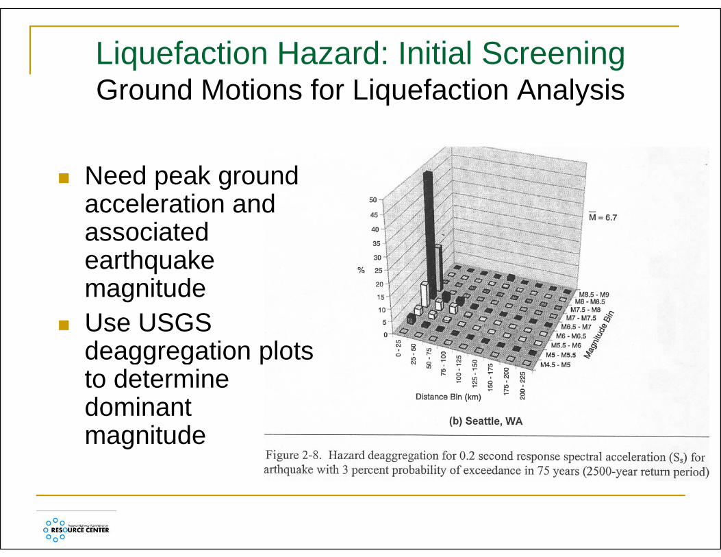
Liquefaction Hazard: Initial Screening Ground Motions for Liquefaction Analysis
Need peak ground acceleration andacceleration and associated earthquake
it dmagnitude Use USGS
deaggregation plotsdeaggregation plots to determine dominantdominant magnitude

Additional Criteria for SHL III and IV
Liquefaction potential is low if:
• Pleistocene age deposits or greater (> 11,000 years old)years old)
• Clay content > 15%, Liquid Limit > 35%, or w% < 90% LL90% LL
• (N1)60 > 30 or qc1 > 160W bl 60 f b l d f• Water table > 60 ft below ground surface

Liquefaction Hazard: Initial Screening
Liquefaction Hazard: Detailed Evaluations
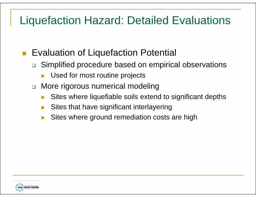
E l ti f Li f ti P t ti l Evaluation of Liquefaction Potential Simplified procedure based on empirical observations
Used for most routine projects Used for most routine projects More rigorous numerical modeling
Sites where liquefiable soils extend to significant depths Sites where liquefiable soils extend to significant depths Sites that have significant interlayering Sites where ground remediation costs are high

Liquefaction Hazard: Detailed Evaluations
Procedures based on three primary source Procedures based on three primary source documents
P di f th 1996 NCEER W k h ( Proceedings of the 1996 NCEER Workshop (now MCEER) on evaluating liquefaction resistance (Youd and Idriss 1997; Youd et al 2001)and Idriss, 1997; Youd et al., 2001).
2009 AASHTO Guide Specification for LRFD Seismic Bridge Design.g g
Procedures for implementing guidelines for analyzing and mitigating liquefaction in California (SCEC, 1999).g g q ( )

Liquefaction Evaluationq
L b t t ti ll t d iLaboratory testing generally not used in practice
Correlation with SPT, CPT most common• Correlation with VS can be used where CPT,
SPT not possible
Two step procedure:Determine if liquefaction is triggered1. Determine if liquefaction is triggered
2. Assess the consequences of liquefaction

In Situ Evaluation MethodsStandard Penetration Test sensitive to test procedures – need careful
tests to prevent misleading resultstests to prevent misleading results Use hammer energy measurements on
i t t j timportant projects
Cone Penetration Testf d f i t t bilit preferred for consistency, repeatability
generally more cost effectiveg y
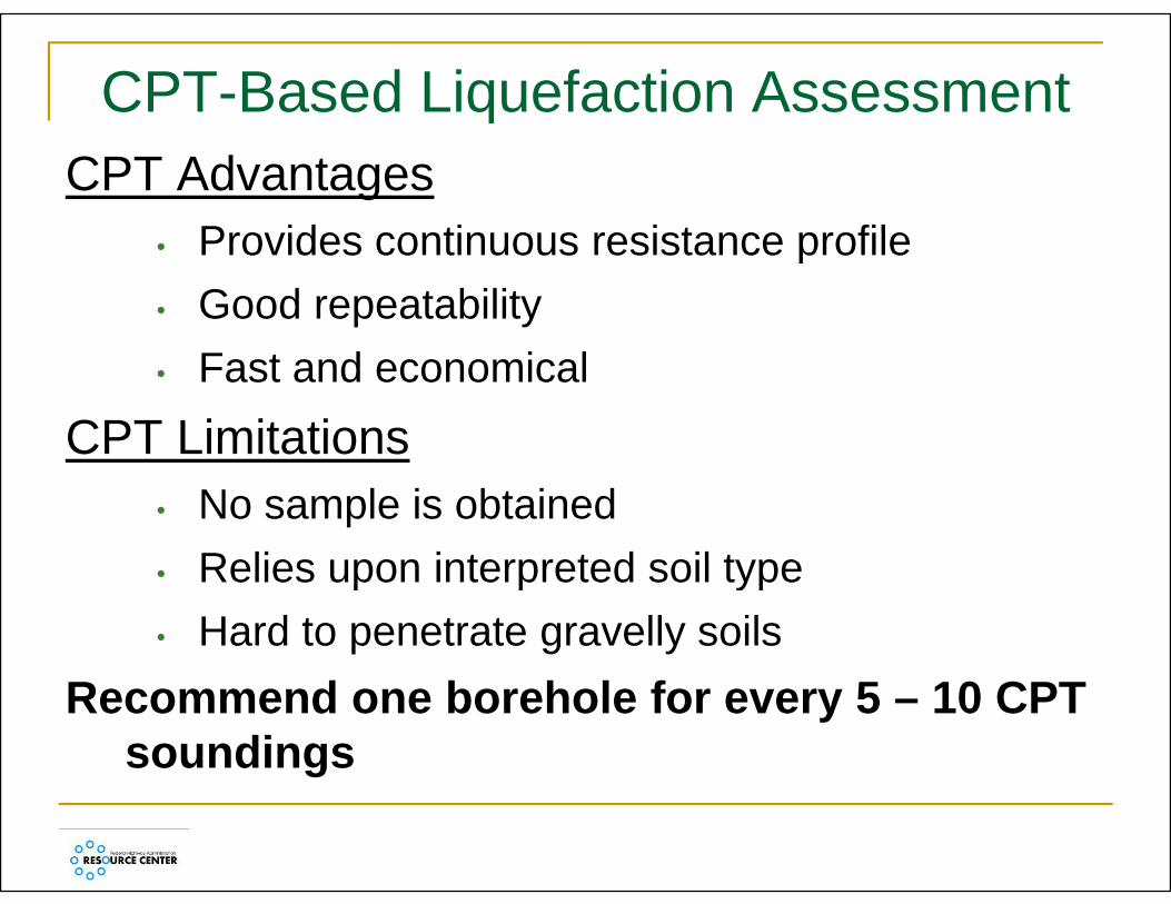
CPT-Based Liquefaction AssessmentqCPT Advantages
Pro ides contin o s resistance profile• Provides continuous resistance profile• Good repeatability• Fast and economical
CPT LimitationsCPT Limitations• No sample is obtained
Relies upon interpreted soil type• Relies upon interpreted soil type• Hard to penetrate gravelly soils
Recommend one borehole for every 5 – 10 CPT soundings
Basic Considerations – Cyclic yResistance
Cyclic resistance of the soil described by cyclic resistance ratio (CRR) • This is the term that describes the soil
“capacity”capacity• Based upon SPT or CPT test results• Cyclic resistance is normalized by the
vertical effective stress prior to thevertical effective stress prior to the ground shaking

Basic Considerations – Cyclic yLoading
Cyclic loading described by cyclic stress ratio (CSR)( )• This term describes the cyclic load, or
“demand”demand• Directly related to the intensity of the ground
motionsmotions• The cyclic loading is also normalized by the
ti l ff ti tvertical effective stressIf CRR/CSR < 1, liquefaction is triggered

Liquefaction Hazard: Detailed Evaluations
Field ExplorationL i f Li fi bl S il Location of Liquefiable Soils
Location of Groundwater LevelDepth of Liq efaction Depth of Liquefaction
Field Exploration Methods Standard Penetration Test (SPT) Standard Penetration Test (SPT) Cone Penetration Test (CPT)

Liquefaction Hazard: Detailed Evaluations CPT Data Evaluation
Q arr
CPT-3 B-1X X'
S d t Silt S d 0
+20
4SMSM
CPT-1CPT-2 Backfill
(22)
RockRip-Rap
Quarry
n (ft
)Sand
Sand to(Hydraulic Fill)
Silty Sand
-40
-20
04(13)
7(31)
40(31)
44(>60)
34
SMSMSMSMSMSMSMSM
SP-SMSP SM
RunFill
Marine
Harbor Bottom Sediments E
leva
tion
-60
40(7)7
(13)11(13)18
(>50)17
(>50)
SP-SMCLCLMLMHMHSCSCSP
Clay / Silt(Lagoonal Clay)
S d Sil S d-80
32
>50(>50)
(>50)>50(>50)>50(>50)>50
SMSMSMSMSMSM
0 200 40048400
ance
)on o )
0 200 40048
0 200 40048
Tip
Res
ista
nce
(tsf)
Fric
tion
Rat
io(%
) Tip
Res
ista
nce
(tsf)
Fric
tion
Rat
io(%
)
Sand to Silty Sand(Lakewood-San
Pedro Formation)-120
-100
ScaleZone of Liquefaction0 20 40 feet
Key
>50SMTip
Res
ista
(tsf)
Fric
tioR
atio
(%)
SPT
Blow
coun
ts
(N)
Soil
lass
ifica
tion
(USC
S)
qBCl
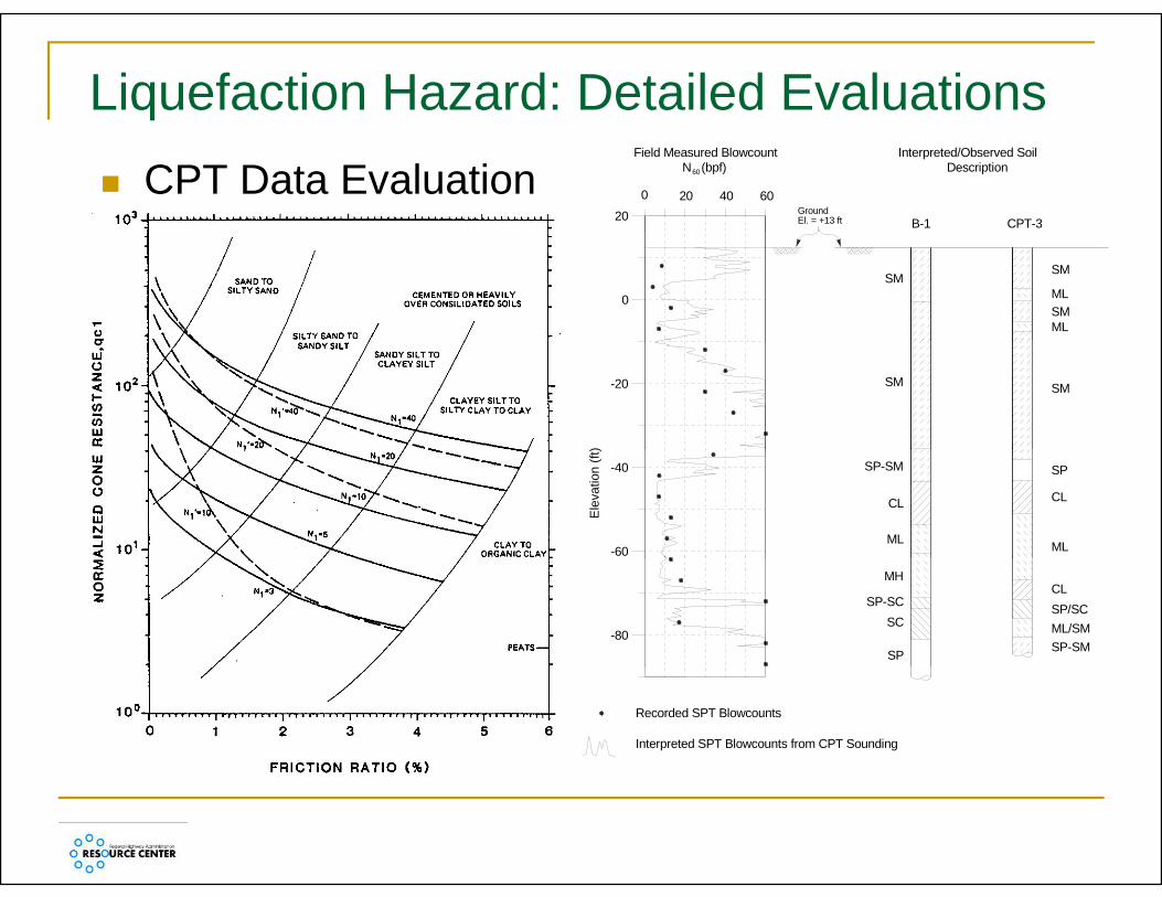
Liquefaction Hazard: Detailed Evaluations CPT Data Evaluation 0 40
20 GroundEl. = +13 ft
6020
Field Measured BlowcountN (bpf)60 Description
Interpreted/Observed Soil
B-1 CPT-3
0
SMSM
MLSMML
-20
)
SM SM
-60
-40
Ele
vatio
n (ft
)
SP-SM
CL
ML
SP
CL
ML
-80
MH
SP-SCSC
SP
CLSP/SCML/SMSP-SM
Recorded SPT Blowcounts
Interpreted SPT Blowcounts from CPT Sounding
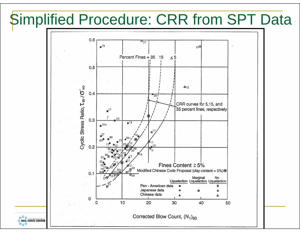
Simplified Procedure: CRR from SPT Data

Magnitude Scaling Factorg g

Simplified Procedure: CRR from CPT Data

Simplified Procedure: CSR Determination
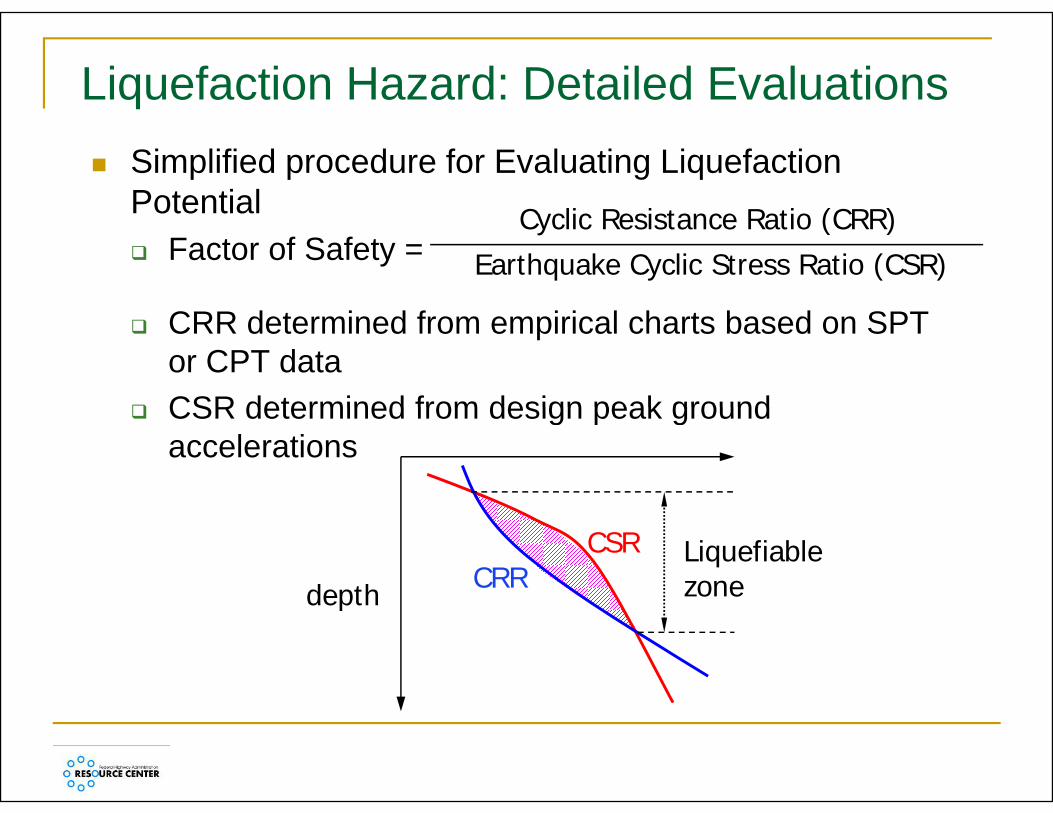
Liquefaction Hazard: Detailed Evaluations Simplified procedure for Evaluating Liquefaction
Potential C li R i t R ti (CRR)Potential Factor of Safety =
Cyclic Resistance Ratio (CRR)Earthquake Cyclic Stress Ratio (CSR)
CRR determined from empirical charts based on SPT or CPT data
CSR determined from design peak ground CSR determined from design peak ground accelerations
depth
CSRCRR
Liquefiable zonedepth

Liquefaction Hazard: Detailed Evaluations
Example of a Liquefaction Triggering Analysis for a Single SPT Boring (Idriss andBoulanger 2008)Boulanger, 2008)

Liquefaction Hazard: Detailed EvaluationsNumerical Modeling Equivalent linear or non-linear site-specific, one Equivalent linear or non linear site specific, one
dimensional ground response analyses Require representative acceleration time histories to q p
define input ground motions Common approach is equivalent linear total stress
computer program “SHAKE” for CSR (apply 0.65 factor)
Alternative is non-linear effective stress methods to determine pore water pressure developmentLi l i l li bl f d ti Linear analysis less reliable for ground motions > 0.4g in softer soils or where max shear strain amplitude > 1 – 2%amplitude > 1 2%
Liquefaction Hazard: Detailed Evaluations
Liquefaction results used to evaluate potential severity of the following hazards:severity of the following hazards: Flow Failures Limited Lateral Spreads Limited Lateral Spreads Ground Settlement
If liquefaction safety factor < 1.3, liquefaction q y , qinduced hazard should be evaluated based on: Vulnerability of Structure Acceptable Level of Risk Damage Potential Design Earthquake Magnitude Design Earthquake Magnitude Uncertainty in SPT/CPT derived liquefaction strengths

Liquefaction Induced Hazard Evaluation
Flow Failures Flow Failures Potential massive
translational failuretranslational failure when static factor of safety <1 where
t li f tipost-liquefaction undrained residual strength mobilized.g

Liquefaction Induced Hazard Evaluation
L t l S di Lateral Spreading Progressive down slope deformation under cyclic
inertial loading during time intervals when F S <1inertial loading during time intervals when F.S.<1 Four approaches to assess the magnitude of lateral
spread displacement:p p1. Youd et. al empirical approach2. Newmark time history analyses3. Simplified Newmark Charts4. Numerical Modeling
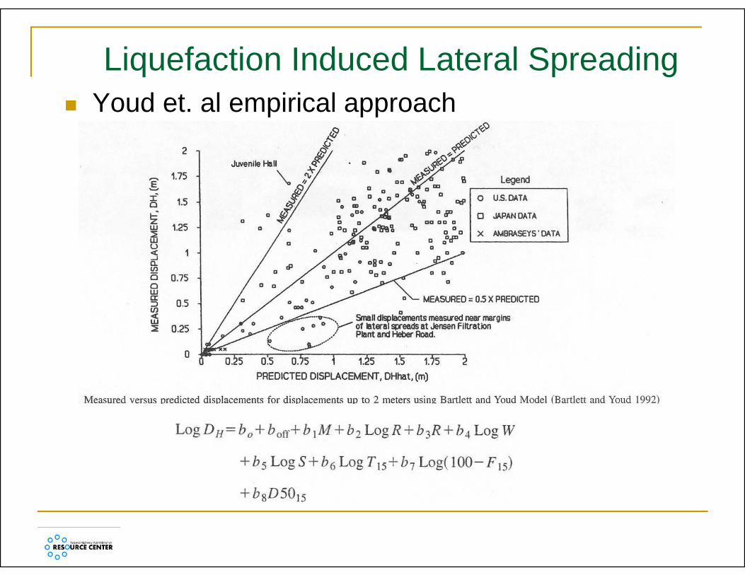
Liquefaction Induced Lateral Spreading Youd et. al empirical approach

Liquefaction Induced Lateral Spreading
Newmark time history analyses

Liquefaction Induced Lateral Spreading Newmark time history analysis – Simplified Charts

Volumetric Strain in Liquefied Soilsq
Notes for application
•Based on SPT data•Similar in form to the Simplified Liquefaction Procedure•The chart applies for M•The chart applies for M 7.5

Evaluation of Soil Settlement Hazard
Tokimatsu and Seed (1987) Methodology:M t th d f t t d d Most common method for saturated and dry/unsaturated sands
Estimates valid only for level ground sites w/o potential for lateral spreading
Cyclic strength adjustments required for fines content
Caution required for stratified subsurface conditionsconditions
Multiply settlement estimate by 2 to account for multidirectional shakingmultidirectional shaking
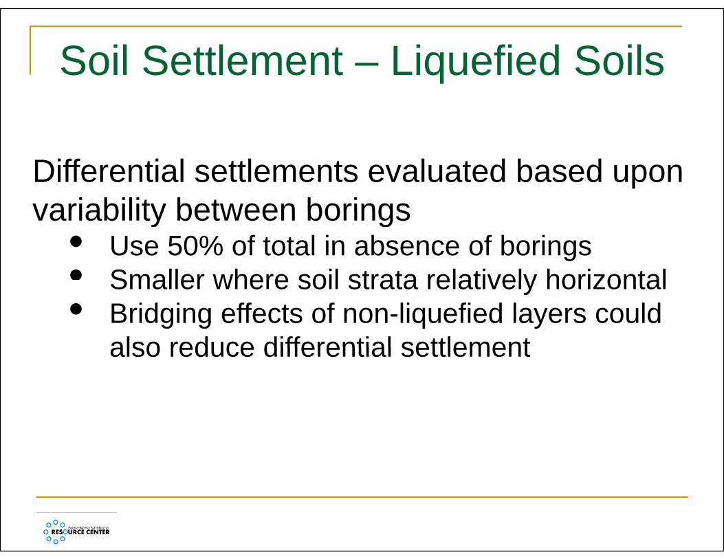
Soil Settlement – Liquefied Soilsq
Differential settlements evaluated based upon variability between boringsvariability between borings
• Use 50% of total in absence of borings• Smaller where soil strata relatively horizontalSmaller where soil strata relatively horizontal• Bridging effects of non-liquefied layers could
also reduce differential settlementalso reduce differential settlement

Volumetric Strain in Liquefied Soils
Ishihara and Yoshimine (1992)

MITIGATION OF LIQUEFIABLE SITES

Bridges on Liquefiable Soils:Bridges on Liquefiable Soils:
Identify Potential Liquefiable Soil Strata Identify Potential Liquefiable Soil Strata Check for Flow Slide Potential (FOS < 1) Determine Lateral Spread Displacements
(FOS > 1) using Newmark Method Evaluate Pile/Soil Interaction Mechanism Evaluate Pile Pinning Effects Evaluate Pile Pinning Effects Evaluate Mitigation Options if Needed
Ground Improvement Ground Improvement Pin Piles

Summary of Ground Improvement Methods (cont.)

Summary of Ground Improvement Methods (cont.)

Summary of Ground Improvement Methods (cont.)
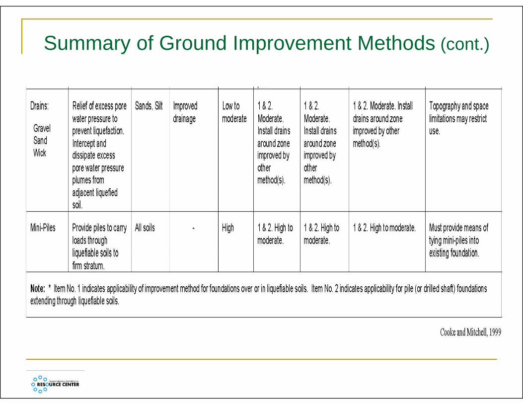
Summary of Ground Improvement Methods (cont.)
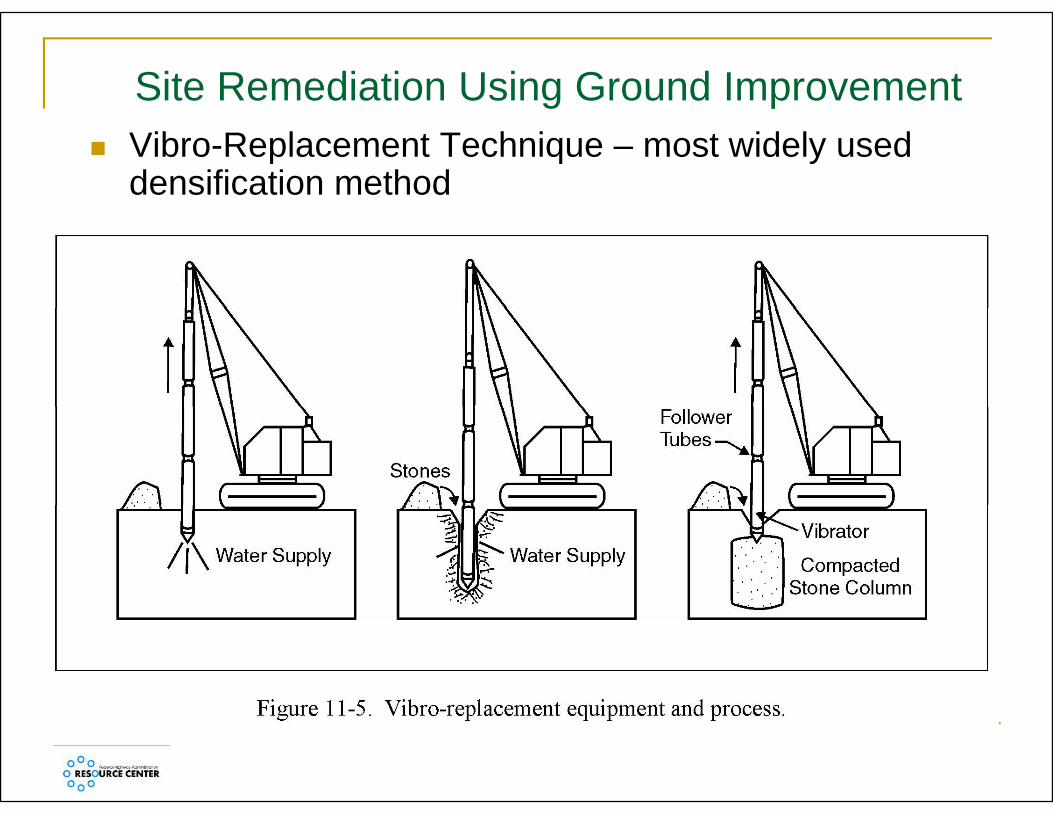
Site Remediation Using Ground Improvement Vibro-Replacement Technique – most widely used
densification method

Site Remediation Using Ground Improvement (cont.) Representative Applications

Site Remediation Using Ground Improvement (cont.) Compaction Grouting

Learning Outcomesg
Be able to describe:Be able to describe: Types and impacts of liquefaction induced
h dhazards Methods for evaluating liquefaction hazards Methods for mitigating liquefiable sites.

Q ti ?Questions?