Embed Size (px)
Citation preview

ACI Structural Journal/March-April 2007 227
ACI Structural Journal, V. 104, No. 2, March-April 2007.MS No. S-2006-138 received March 29, 2006, and reviewed under Institute publication
policies. Copyright © 2007, American Concrete Institute. All rights reserved, includingthe making of copies unless permission is obtained from the copyright proprietors. Pertinentdiscussion including author’s closure, if any, will be published in the January-February2008 ACI Structural Journal if the discussion is received by September 1, 2007.
ACI STRUCTURAL JOURNAL TECHNICAL PAPER
Existing reinforced concrete (RC) columns detailed with poor lapsplices and inadequate transverse confinement reinforcement inthe potential plastic hinge regions near beam-column joints,characteristic of pre-1970 design provisions, are found to bedeficient for the strength and ductility demands imposed by earth-quake loading. The work reported herein was directed toward theevaluation of the effectiveness of carbon fiber-reinforced polymer(CFRP) jackets in strengthening and repair of such columns undersimulated earthquake loading. A total of 12 columns, six 356 mm(14 in.) diameter circular and six 305 mm (12 in.) square, wereconstructed and tested. The columns were 1.47 m (58 in.) long andhad a 510 x 760 x 810 mm (20 x 30 x 32 in.) stub at one end with aconstruction joint at the interface and spliced longitudinal bars inthe columns. The variables studied in this program included effectof the presence of lap splices, the effectiveness of CFRP in pre-earthquake strengthening and post-earthquake retrofitting of deficientcolumns, as well as effects of level of axial load, shape of columncross section, and transverse steel reinforcement details. TheCFRP retrofitting technique was found to be effective in enhancingthe seismic resistance of the columns and resulted in more stablehysteresis curves with lower stiffness and strength degradationsas compared with the unretrofitted columns.
Keywords: columns; confinement; ductility; lap splice; rehabilitation.
INTRODUCTIONMost of the existing reinforced concrete structures
designed and constructed prior to 1970 in accordance withthe prevalent design standards may have inadequate seismicresistance. As a result, during the recent earthquakes, manyof these structures collapsed or suffered severe damage. TheLoma Prieta earthquake alone caused damage to over 80bridges, resulting in 40 deaths, $1.8 billion in damage, andsevere economic disruptions.1 These structures weredesigned and detailed to resist primarily gravity loads anddid not possess adequate lateral strength and ductility andthus the new codes have rendered them substandard. Lapsplices are used in the construction of most reinforced concretestructures for preserving the continuity of reinforcementwithin the structural members. These splices were usuallyprovided in the potential plastic hinge regions at the base ofthe columns, just above a construction joint and all the barswere usually spliced at the same section. This results in aconsiderable reduction in the strength and ductility of thestructure. Because most of these pre-1971 structures weredetailed only for gravity loading, the splice lengths in thecolumns were designed as per the code requirements for barsunder axial compression with little or no flexure. Earthquakeforces, however, result in transverse loading causing thespliced bars to be subjected to large tensile forces andinelastic deformations, which lead to high strength and ductilitydemands. The situation is further worsened by inadequatetransverse reinforcement to confine the concrete and thusthere is a lack of adequate clamping pressure across the fracture
surfaces in the splice zone. The performance of such columnswill thus be limited by the premature failure of the splices.The changes implemented in the ACI design practice as perthe splice configuration (length, bond strength, and detailingof added stirrups/ties) over the years until the current designpractice has been outlined in a literature review.2
There are considerable research efforts being directed atdeveloping and applying retrofit strategies to upgrade theseismic performance of deficient structures. Traditionalstrengthening systems include steel and reinforced concretejacketing. Several researchers have validated experimentallyas well as through field applications the effectiveness ofsteel jackets in providing desired confinement to the coreconcrete and thereby improving the seismic performance ofdeficient columns.1,3-6
The rapid deterioration of the infrastructure coupled withrestrained public spending, however, demands constantoptimization of the repair and strengthening techniques toimprove and economize the retrofitting process of the largenumber of existing, seismically deficient structures. This hasled to research towards the use of new polymers andcomposite materials to develop alternative retrofittingtechniques that are easy to implement, economical from aperspective of life-cycle cost, and more durable. Onestrengthening scheme that is finding rapid acceptanceinvolves the use of externally bonded fiber-reinforcedpolymer (FRP) (carbon, glass, and aramid) jackets. Researchwork is being carried out at various research centers aroundthe world in determining the effectiveness of FRP reinforcementin strengthening columns rendered deficient by the modernseismic codes due to poor confinement and splice details.2,7-15
RESEARCH SIGNIFICANCEThe current study was directed toward an evaluation of the
effectiveness of carbon FRP (CFRP) jackets in enhancingthe seismic resistance of non-ductile reinforced concretecolumns with poor details of longitudinal bar splices inplastic hinge regions and inadequate transverse confinement.Results from this work are compared with the databasealready available from similar FRP-retrofitted columns thatdid not contain lap splices in the hinge regions.7,8 The objectivesof this research program were to: 1) evaluate the degradationof column strength and ductility due to the presence of lapspliced longitudinal bars; 2) determine the effectiveness ofCFRP in pre-earthquake strengthening and post-earthquakerepair of such deficient columns; 3) study the effects of shape
Title no. 104-S24
Seismic Upgrade with Carbon Fiber-Reinforced Polymer of Columns Containing Lap-Spliced Reinforcing Barsby Kumar K. Ghosh and Shamim A. Sheikh

ACI Structural Journal/March-April 2007228
(circular or square) of column cross section on the effectivenessof CFRP retrofitting; 4) determine the effects of confinement onlap splices; and 5) investigate the effect of axial load level.
EXPERIMENTAL PROGRAMSpecimen details
Twelve reinforced concrete columns (six circular and sixsquare) were constructed and tested under combined axialload and reversed cyclic lateral displacement excursionssimulating earthquake. The circular columns had a diameterof 356 mm (14 in.) while the square ones had a section sizeof 305 mm (12 in.). The columns were 1.47 m (58 in.) longand had a 510 x 760 x 810 mm (20 x 30 x 32 in.) stub at oneend with a construction joint at the interface and splicedlongitudinal bars in the columns. The dimensional details ofthe columns are presented in Fig. 1(a). The test column repre-sented the portion between the point of contra-flexure and thesection of maximum moment at the base of the column. Thestub represented a supporting member of the column like abeam column joint or a footing. In all the specimens, the ratioof the column core area, measured center-to-center of externalhoops, to the gross area of the column section was kept atapproximately 75%. The specimens are typical representationsfrom pre-1971 multi-story building and bridge piers.
Table 1 lists four groups of columns out of which the 12columns of the first two groups represent specimens testedunder the present project. Group III lists the details of someof the circular columns tested by Sheikh and Yau,7 whileunder Group IV, the details of two square columns tested byIacobucci and Sheikh8 are shown. All of the Group III andIV columns have the same dimensional and reinforcement
details as the present columns, except that they were reinforcedwith continuous longitudinal bars. For columns in Groups Iand II, the first letter in the specimen designation indicatesthe shape of the column, C being circular and S being square.A or B refers to the transverse steel configuration of thespecimens. F1, if present, indicates that the column waswrapped with one layer of CFRP and is followed by thetesting sequence number of the specimen. The last letter Nrefers to normal-strength concrete.
Reinforcing steel—Three types of deformed steel barswere used to construct the reinforcing cages of the specimens.Grade 400, 20M (area = 0.465 in.2 [300 mm2]) bars andGrade 60 U.S. No. 3 bars were used for the longitudinal andthe transverse reinforcement in the columns, respectively.Grade 400, 10M (area = 0.155 in.2 [100 mm2]) bars wereused to construct the stub reinforcing cages. The stress-strain curves of steel bars along with the yield and ultimatestress and strain values are presented in Fig. 2. The columnswere detailed as per the provisions of the ACI 318-5616 andACI 318-6317 codes.
The circular columns were reinforced with six 20M andthe square columns with eight 20M longitudinal bars thatwere lap spliced in the column for a length of 470 mm (18.5 in.)from the stub-column interface (Fig. 1). Two configurationsof transverse reinforcement, Types A and B, were used. Forthe circular specimens, Type A columns were detailed withU.S. No. 3 hoops at 300 mm (11.8 in.) spacing while Type Bcolumns consisted of U.S. No. 3 spirals at 80 mm (3.1 in.).For the square specimens, Type A columns were reinforcedwith only one set of U.S. No. 3 ties at 300 mm (11.8 in.), suchthat only the corner bars were held by corners of the ties. TheType B square specimens were reinforced with two sets ofU.S. No. 3 ties at 300 mm (11.8 in.) so that every longitudinalbar was laterally supported by tie corners. To ensure thatfailure of the specimens occurs at the potential plastic hingeregion, beyond a distance of approximately 600 mm (23.6 in.)from the stub-column interface, the spacing of the transversesteel was reduced to approximately half the specifiedspacing in the test zone as shown in Fig. 1.
The reinforcement for the stub consisted of 10M horizontaland vertical stirrups at 64 mm (2.5 in.) spacing. Additional10M bars with 135-degree hooks were added at two sides toincrease stub stiffness. The reinforcement details are illustratedin Fig. 1.
Concrete—The stubs and the columns were cast with twoseparate batches of concrete on two consecutive days tosimulate field conditions and to form a construction joint atthe interface. Concrete with a target strength of 25 MPa(3630 psi) was used. Concrete strength was monitored by
Kumar K. Ghosh is a Bridge Engineer with the California Department of Transportation.He received his PhD in structural engineering in 2006 from the University of California,San Diego, Calif., and his master of applied science degree in 2002 from the University ofToronto, Toronto, Ontario, Canada. His research interests include earthquake-resistantdesign of structures and applications of advanced composite materials.
Shamim A. Sheikh, FACI, is a Professor of civil engineering at the University ofToronto. He is a member and former Chair of Joint ACI-ASCE Committee 441, ReinforcedConcrete Columns, and is a member of ACI Committee 374, Performance-Based SeismicDesign of Concrete Buildings. His research interests include earthquake resistanceand seismic upgrade of concrete structures, confinement of concrete, use of fiber-reinforced polymer in concrete structures, and expansive cement and its applications.He received the ACI Structural Research Award in 1999.
Fig. 1—Specimen details: (a) dimensional details; (b)reinforcement details of square and Type A circular columns;(c) reinforcement details of Type B circular columns; and(d) sectional details.
Fig. 2—Stress-strain behavior of steel.
ACI Structural Journal/March-April 2007 229
regular testing of 150 x 300 mm (6 x 12 in. nominal) concretecylinders, which were cast with the specimens. The strength-age relationship thus developed was used to obtain the strengthof each specimen at the time of testing.2
Fiber-reinforced polymers—A commercially availableFRP system was used for retrofitting. The epoxy consisted oftwo components, A and B, mixed in the ratio of 100 parts ofA with 42 parts of B using a mixer for 5 minutes at a speedof 400 to 600 rpm. The fabric was saturated with epoxy anda layer of epoxy was also applied on the column surfaceusing rollers. The fabric was thereafter wrapped around thecolumns with fiber orientation in the circumferential direction.The corners of square columns were rounded to facilitateFRP wrapping using concave wood sections, with a 16 mm(0.63 in.) radius, placed inside the forms.
Three circular and four square columns were wrappedwith one layer of 1 mm (0.04 in.) thick and 610 mm (24 in.)wide CFRP in the potential plastic hinge regions adjacent tothe stub-column interface. The column outside the testregion was wrapped with three layers of 1.25 mm (0. 049 in.)thick glass FRP (GFRP) to ensure that failure occurred in thetest region. The average tensile strength/unit width/layer andthe rupture strain of the CFRP measured from coupon testswere 1019 N/mm (5819 lb/in.) and 0.0129, respectively. Thecorresponding values for GFRP were 568 N/mm (3243 lb/in.)and 0.0228. Stress-strain curves were essentially linear up tofailure for both FRPs.
Instrumentation—The longitudinal and transverse reinforcingbars of the specimens were instrumented extensively todetermine the steel strains at various locations (Fig. 3). In theB-type circular columns, the first three rings of the spiralswere instrumented, while in the other specimens the first two
sets of hoops closest to the stub were instrumented withstrain gauges of 5 mm (0.20 in.) gauge length. In addition,six external strain gauges of 60 mm (2.4 in.) gauge length
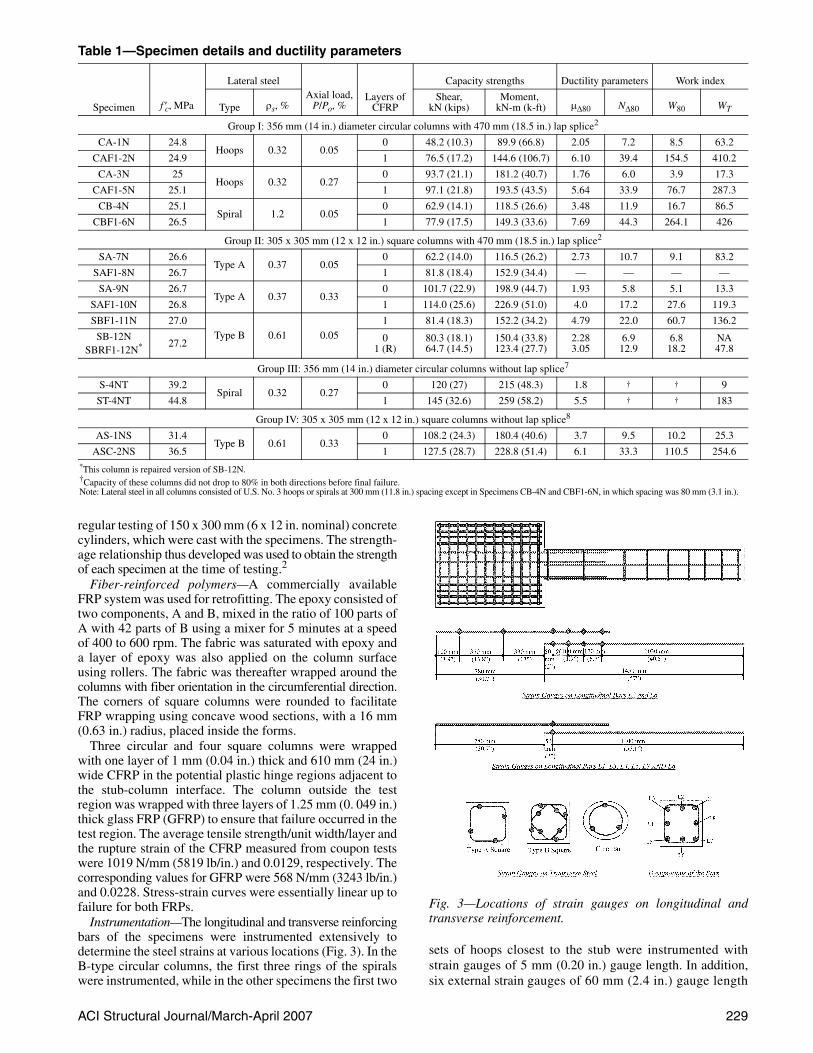
Table 1—Specimen details and ductility parameters
Specimen f ′c, MPa
Lateral steelAxial load,
P/Po, %Layers of
CFRP
Capacity strengths Ductility parameters Work index
Type ρs, %Shear,
kN (kips)Moment,
kN-m (k-ft) μΔ80 NΔ80 W80 WT
Group I: 356 mm (14 in.) diameter circular columns with 470 mm (18.5 in.) lap splice2
CA-1N 24.8Hoops 0.32 0.05
0 48.2 (10.3) 89.9 (66.8) 2.05 7.2 8.5 63.2
CAF1-2N 24.9 1 76.5 (17.2) 144.6 (106.7) 6.10 39.4 154.5 410.2
CA-3N 25Hoops 0.32 0.27
0 93.7 (21.1) 181.2 (40.7) 1.76 6.0 3.9 17.3
CAF1-5N 25.1 1 97.1 (21.8) 193.5 (43.5) 5.64 33.9 76.7 287.3
CB-4N 25.1Spiral 1.2 0.05
0 62.9 (14.1) 118.5 (26.6) 3.48 11.9 16.7 86.5
CBF1-6N 26.5 1 77.9 (17.5) 149.3 (33.6) 7.69 44.3 264.1 426
Group II: 305 x 305 mm (12 x 12 in.) square columns with 470 mm (18.5 in.) lap splice2
SA-7N 26.6Type A 0.37 0.05
0 62.2 (14.0) 116.5 (26.2) 2.73 10.7 9.1 83.2
SAF1-8N 26.7 1 81.8 (18.4) 152.9 (34.4) — — — —
SA-9N 26.7Type A 0.37 0.33
0 101.7 (22.9) 198.9 (44.7) 1.93 5.8 5.1 13.3
SAF1-10N 26.8 1 114.0 (25.6) 226.9 (51.0) 4.0 17.2 27.6 119.3
SBF1-11N 27.0Type B 0.61 0.05
1 81.4 (18.3) 152.2 (34.2) 4.79 22.0 60.7 136.2
SB-12NSBRF1-12N* 27.2 0
1 (R)80.3 (18.1)64.7 (14.5)
150.4 (33.8)123.4 (27.7)
2.283.05
6.912.9
6.818.2
NA47.8
Group III: 356 mm (14 in.) diameter circular columns without lap splice7
S-4NT 39.2Spiral 0.32 0.27
0 120 (27) 215 (48.3) 1.8 † † 9
ST-4NT 44.8 1 145 (32.6) 259 (58.2) 5.5 † † 183
Group IV: 305 x 305 mm (12 x 12 in.) square columns without lap splice8
AS-1NS 31.4Type B 0.61 0.33
0 108.2 (24.3) 180.4 (40.6) 3.7 9.5 10.2 25.3
ASC-2NS 36.5 1 127.5 (28.7) 228.8 (51.4) 6.1 33.3 110.5 254.6*This column is repaired version of SB-12N.†Capacity of these columns did not drop to 80% in both directions before final failure.Note: Lateral steel in all columns consisted of U.S. No. 3 hoops or spirals at 300 mm (11.8 in.) spacing except in Specimens CB-4N and CBF1-6N, in which spacing was 80 mm (3.1 in.).
Fig. 3—Locations of strain gauges on longitudinal andtransverse reinforcement.
230 ACI Structural Journal/March-April 2007
were used in each of the retrofitted specimens to measurethe strain in the CFRP in the direction of fibers. One gaugewas placed at each side face of the retrofitted columns at 75 mm(3 in.) from the stub face. Two gauges each were installed atthe top and bottom faces of the columns. These gauges were 75and 150 mm (3 and 6 in.) away from the stub face.
A total of 18 linear variable differential transducers(LVDTs), 10 on one side and eight on the opposite side, weremounted to the rods embedded in the columns to measure thedeformations of the concrete core in the test region of thespecimens (Fig. 4). The gauge lengths for these LVDTsvaried from 55 to 110 mm (2.2 to 4.3 in.) and covered alength of 550 mm (21.6 in.) from the face of the stub.Transverse displacements were measured by LVDTs placedat six locations along the lengths of the specimens.
Test setup and testing procedureAll the columns were tested under constant axial load and
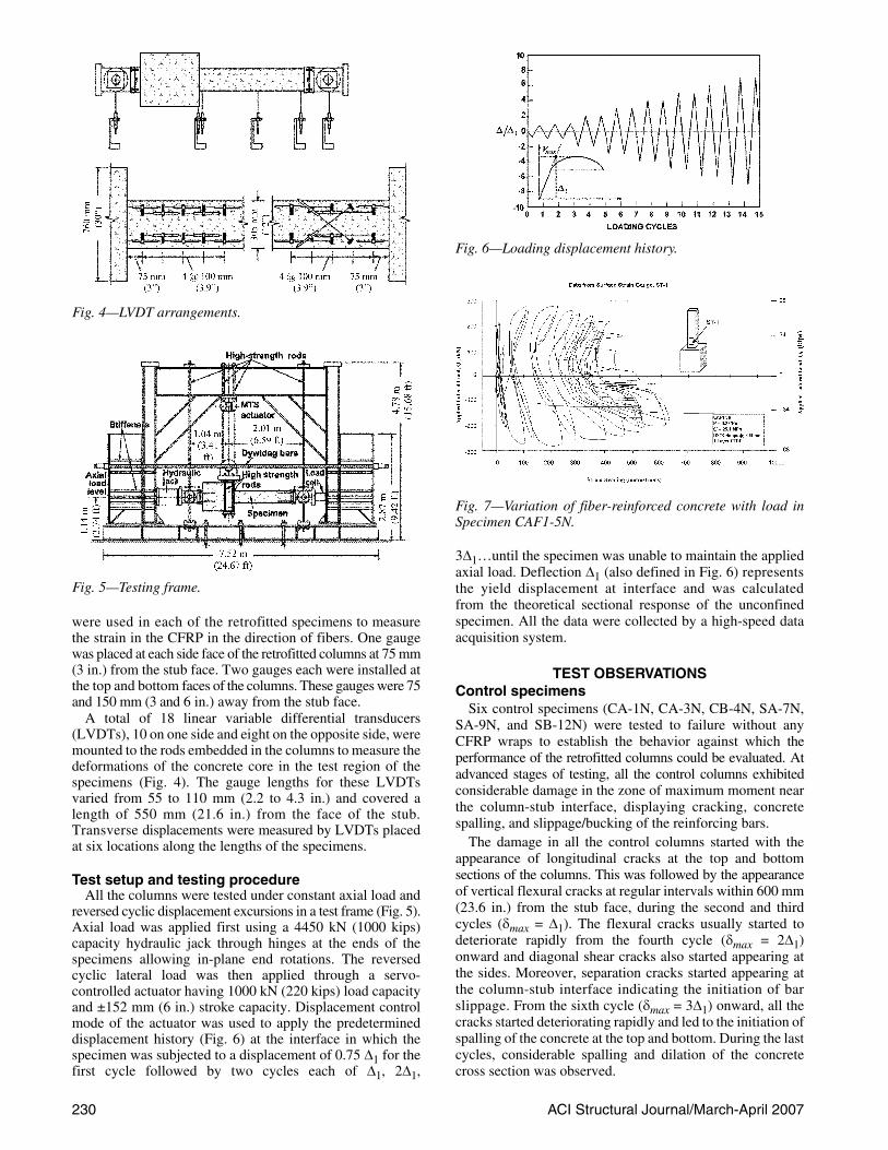
reversed cyclic displacement excursions in a test frame (Fig. 5).Axial load was applied first using a 4450 kN (1000 kips)capacity hydraulic jack through hinges at the ends of thespecimens allowing in-plane end rotations. The reversedcyclic lateral load was then applied through a servo-controlled actuator having 1000 kN (220 kips) load capacityand ±152 mm (6 in.) stroke capacity. Displacement controlmode of the actuator was used to apply the predetermineddisplacement history (Fig. 6) at the interface in which thespecimen was subjected to a displacement of 0.75 Δ1 for thefirst cycle followed by two cycles each of Δ1, 2Δ1,
3Δ1…until the specimen was unable to maintain the appliedaxial load. Deflection Δ1 (also defined in Fig. 6) representsthe yield displacement at interface and was calculatedfrom the theoretical sectional response of the unconfinedspecimen. All the data were collected by a high-speed dataacquisition system.
TEST OBSERVATIONSControl specimens
Six control specimens (CA-1N, CA-3N, CB-4N, SA-7N,SA-9N, and SB-12N) were tested to failure without anyCFRP wraps to establish the behavior against which theperformance of the retrofitted columns could be evaluated. Atadvanced stages of testing, all the control columns exhibitedconsiderable damage in the zone of maximum moment nearthe column-stub interface, displaying cracking, concretespalling, and slippage/bucking of the reinforcing bars.
The damage in all the control columns started with theappearance of longitudinal cracks at the top and bottomsections of the columns. This was followed by the appearanceof vertical flexural cracks at regular intervals within 600 mm(23.6 in.) from the stub face, during the second and thirdcycles (δmax = Δ1). The flexural cracks usually started todeteriorate rapidly from the fourth cycle (δmax = 2Δ1)onward and diagonal shear cracks also started appearing atthe sides. Moreover, separation cracks started appearing atthe column-stub interface indicating the initiation of barslippage. From the sixth cycle (δmax = 3Δ1) onward, all thecracks started deteriorating rapidly and led to the initiation ofspalling of the concrete at the top and bottom. During the lastcycles, considerable spalling and dilation of the concretecross section was observed.
Fig. 4—LVDT arrangements.
Fig. 5—Testing frame.
Fig. 6—Loading displacement history.
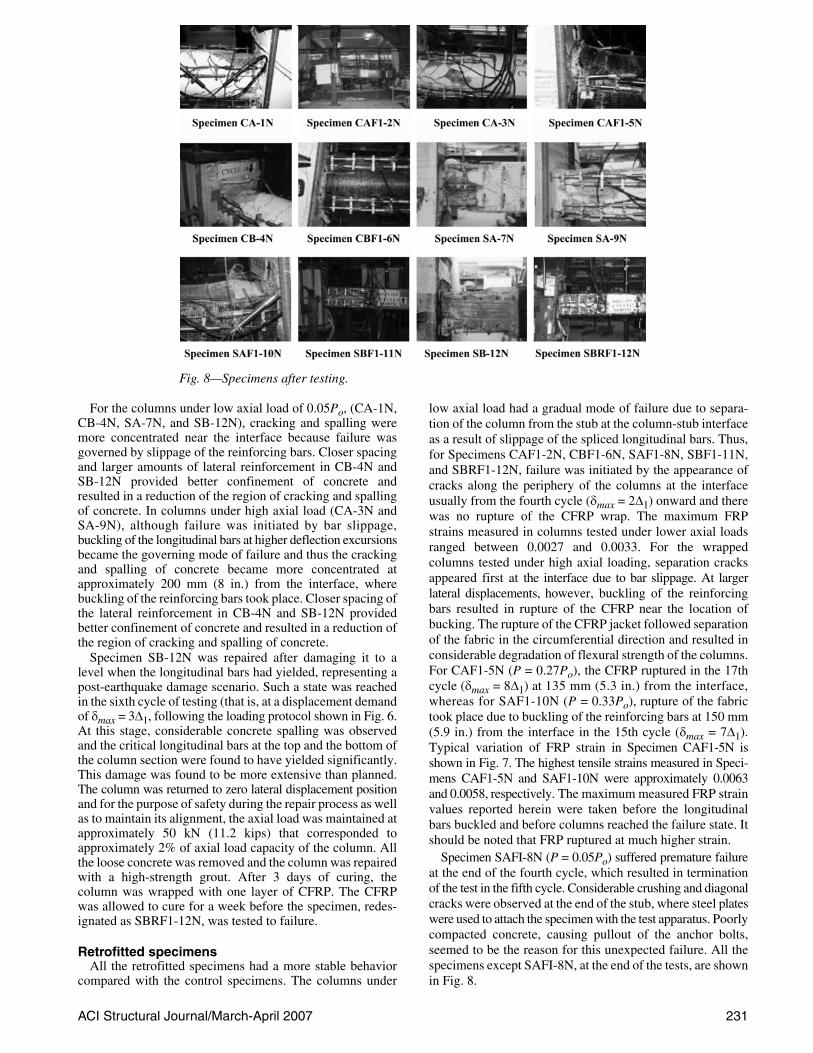
Fig. 7—Variation of fiber-reinforced concrete with load inSpecimen CAF1-5N.
ACI Structural Journal/March-April 2007 231
For the columns under low axial load of 0.05Po, (CA-1N,CB-4N, SA-7N, and SB-12N), cracking and spalling weremore concentrated near the interface because failure wasgoverned by slippage of the reinforcing bars. Closer spacingand larger amounts of lateral reinforcement in CB-4N andSB-12N provided better confinement of concrete andresulted in a reduction of the region of cracking and spallingof concrete. In columns under high axial load (CA-3N andSA-9N), although failure was initiated by bar slippage,buckling of the longitudinal bars at higher deflection excursionsbecame the governing mode of failure and thus the crackingand spalling of concrete became more concentrated atapproximately 200 mm (8 in.) from the interface, wherebuckling of the reinforcing bars took place. Closer spacing ofthe lateral reinforcement in CB-4N and SB-12N providedbetter confinement of concrete and resulted in a reduction ofthe region of cracking and spalling of concrete.
Specimen SB-12N was repaired after damaging it to alevel when the longitudinal bars had yielded, representing apost-earthquake damage scenario. Such a state was reachedin the sixth cycle of testing (that is, at a displacement demandof δmax = 3Δ1, following the loading protocol shown in Fig. 6.At this stage, considerable concrete spalling was observedand the critical longitudinal bars at the top and the bottom ofthe column section were found to have yielded significantly.This damage was found to be more extensive than planned.The column was returned to zero lateral displacement positionand for the purpose of safety during the repair process as wellas to maintain its alignment, the axial load was maintained atapproximately 50 kN (11.2 kips) that corresponded toapproximately 2% of axial load capacity of the column. Allthe loose concrete was removed and the column was repairedwith a high-strength grout. After 3 days of curing, thecolumn was wrapped with one layer of CFRP. The CFRPwas allowed to cure for a week before the specimen, redes-ignated as SBRF1-12N, was tested to failure.
Retrofitted specimensAll the retrofitted specimens had a more stable behavior
compared with the control specimens. The columns under
low axial load had a gradual mode of failure due to separa-tion of the column from the stub at the column-stub interfaceas a result of slippage of the spliced longitudinal bars. Thus,for Specimens CAF1-2N, CBF1-6N, SAF1-8N, SBF1-11N,and SBRF1-12N, failure was initiated by the appearance ofcracks along the periphery of the columns at the interfaceusually from the fourth cycle (δmax = 2Δ1) onward and therewas no rupture of the CFRP wrap. The maximum FRPstrains measured in columns tested under lower axial loadsranged between 0.0027 and 0.0033. For the wrappedcolumns tested under high axial loading, separation cracksappeared first at the interface due to bar slippage. At largerlateral displacements, however, buckling of the reinforcingbars resulted in rupture of the CFRP near the location ofbucking. The rupture of the CFRP jacket followed separationof the fabric in the circumferential direction and resulted inconsiderable degradation of flexural strength of the columns.For CAF1-5N (P = 0.27Po), the CFRP ruptured in the 17thcycle (δmax = 8Δ1) at 135 mm (5.3 in.) from the interface,whereas for SAF1-10N (P = 0.33Po), rupture of the fabrictook place due to buckling of the reinforcing bars at 150 mm(5.9 in.) from the interface in the 15th cycle (δmax = 7Δ1).Typical variation of FRP strain in Specimen CAF1-5N isshown in Fig. 7. The highest tensile strains measured in Speci-mens CAF1-5N and SAF1-10N were approximately 0.0063and 0.0058, respectively. The maximum measured FRP strainvalues reported herein were taken before the longitudinalbars buckled and before columns reached the failure state. Itshould be noted that FRP ruptured at much higher strain.
Specimen SAFI-8N (P = 0.05Po) suffered premature failureat the end of the fourth cycle, which resulted in terminationof the test in the fifth cycle. Considerable crushing and diagonalcracks were observed at the end of the stub, where steel plateswere used to attach the specimen with the test apparatus. Poorlycompacted concrete, causing pullout of the anchor bolts,seemed to be the reason for this unexpected failure. All thespecimens except SAFI-8N, at the end of the tests, are shownin Fig. 8.
Fig. 8—Specimens after testing.
232 ACI Structural Journal/March-April 2007
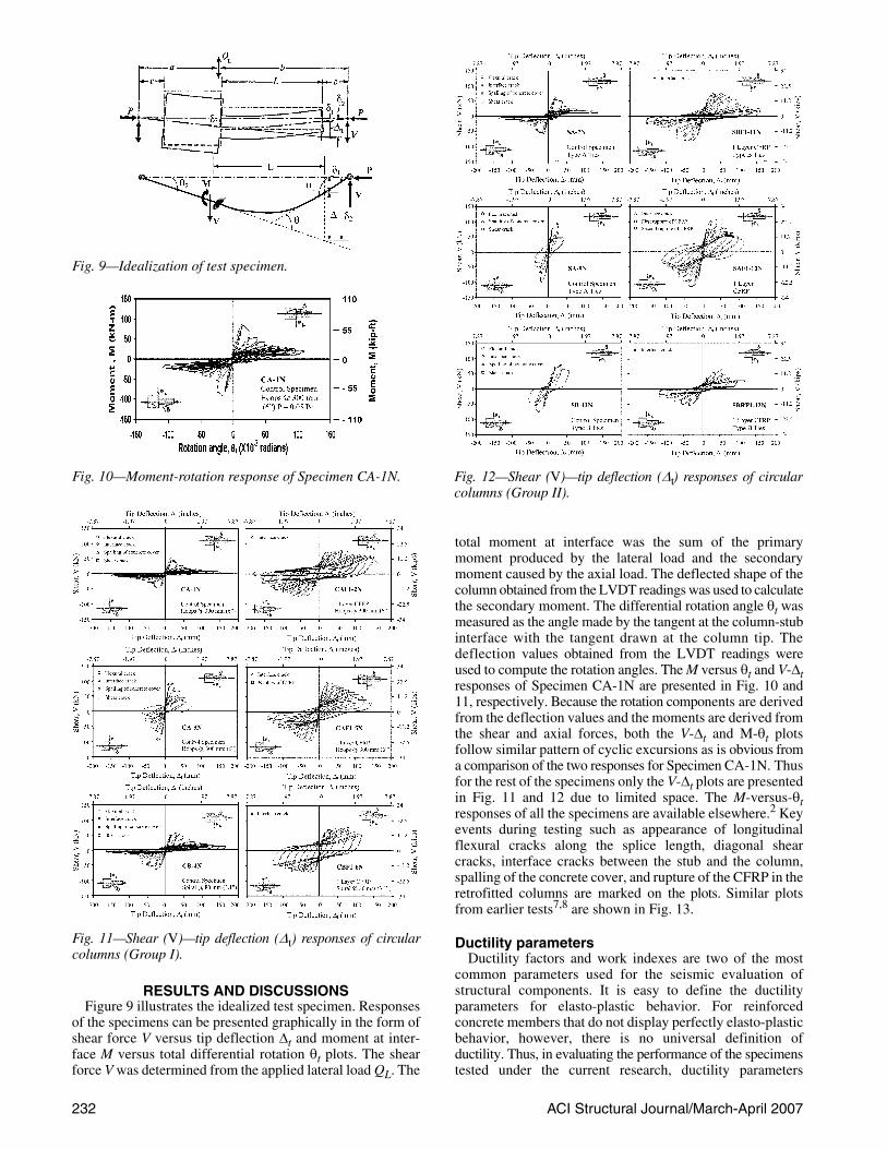
RESULTS AND DISCUSSIONSFigure 9 illustrates the idealized test specimen. Responses
of the specimens can be presented graphically in the form ofshear force V versus tip deflection Δt and moment at inter-face M versus total differential rotation θt plots. The shearforce V was determined from the applied lateral load QL. The
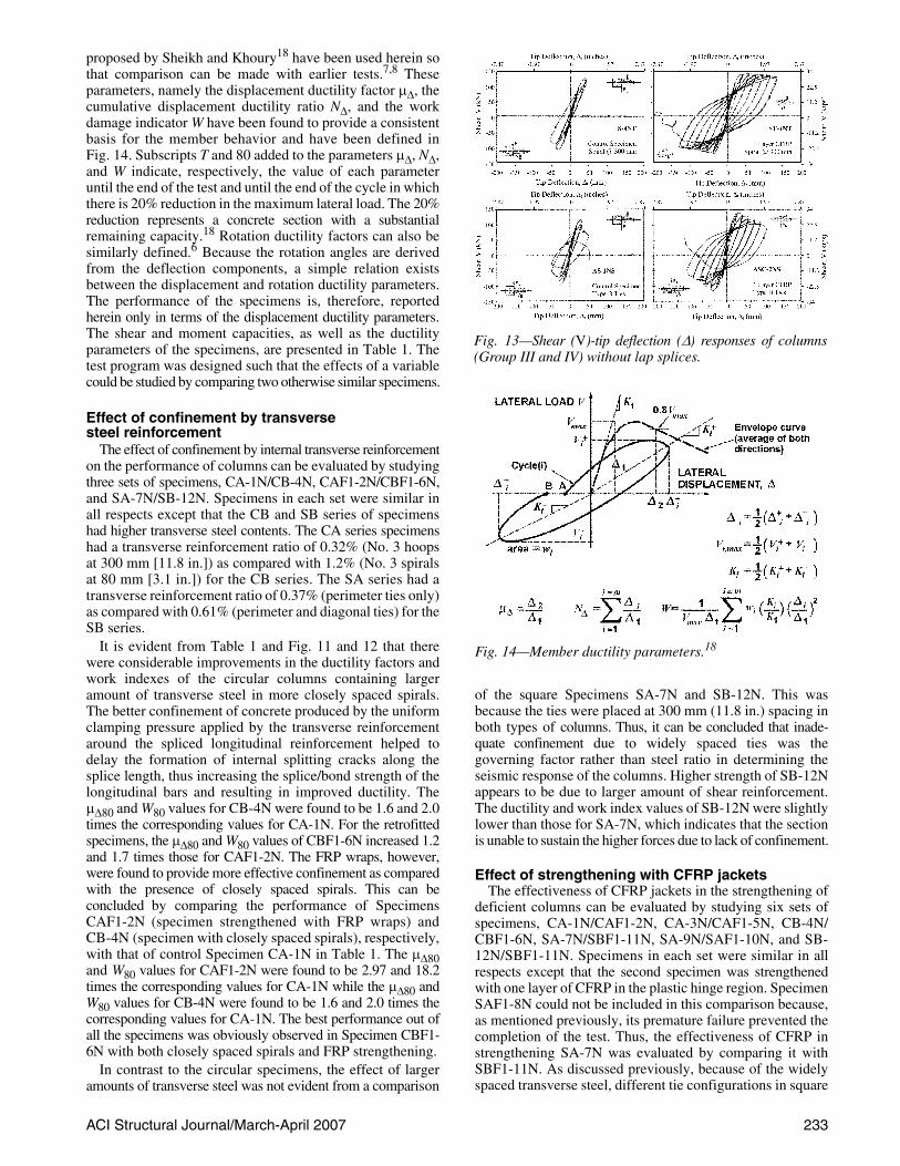
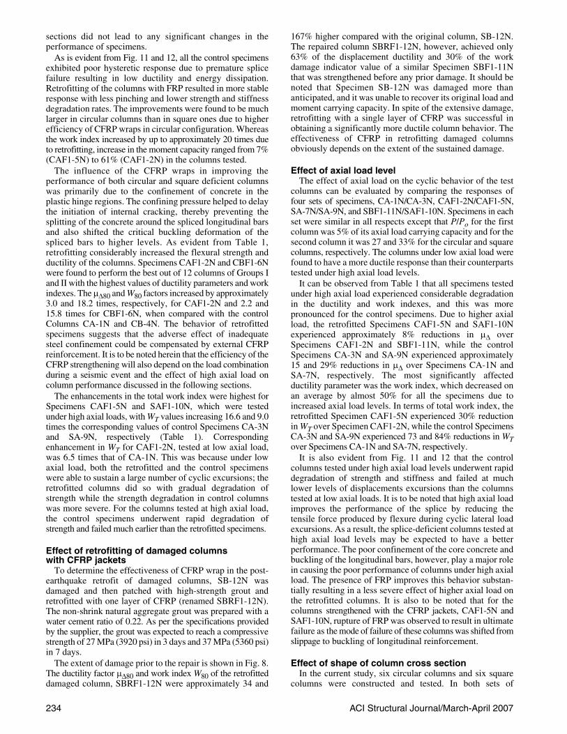
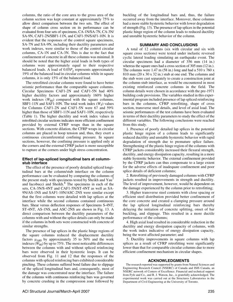
total moment at interface was the sum of the primarymoment produced by the lateral load and the secondarymoment caused by the axial load. The deflected shape of thecolumn obtained from the LVDT readings was used to calculatethe secondary moment. The differential rotation angle θt wasmeasured as the angle made by the tangent at the column-stubinterface with the tangent drawn at the column tip. Thedeflection values obtained from the LVDT readings wereused to compute the rotation angles. The M versus θt and V-Δtresponses of Specimen CA-1N are presented in Fig. 10 and11, respectively. Because the rotation components are derivedfrom the deflection values and the moments are derived fromthe shear and axial forces, both the V-Δt and M-θt plotsfollow similar pattern of cyclic excursions as is obvious froma comparison of the two responses for Specimen CA-1N. Thusfor the rest of the specimens only the V-Δt plots are presentedin Fig. 11 and 12 due to limited space. The M-versus-θtresponses of all the specimens are available elsewhere.2 Keyevents during testing such as appearance of longitudinalflexural cracks along the splice length, diagonal shearcracks, interface cracks between the stub and the column,spalling of the concrete cover, and rupture of the CFRP in theretrofitted columns are marked on the plots. Similar plotsfrom earlier tests7,8 are shown in Fig. 13.
Ductility parametersDuctility factors and work indexes are two of the most
common parameters used for the seismic evaluation ofstructural components. It is easy to define the ductilityparameters for elasto-plastic behavior. For reinforcedconcrete members that do not display perfectly elasto-plasticbehavior, however, there is no universal definition ofductility. Thus, in evaluating the performance of the specimenstested under the current research, ductility parameters
Fig. 9—Idealization of test specimen.
Fig. 10—Moment-rotation response of Specimen CA-1N.
Fig. 11—Shear (V)—tip deflection (Δt) responses of circularcolumns (Group I).
Fig. 12—Shear (V)—tip deflection (Δt) responses of circularcolumns (Group II).
ACI Structural Journal/March-April 2007 233
proposed by Sheikh and Khoury18 have been used herein sothat comparison can be made with earlier tests.7,8 Theseparameters, namely the displacement ductility factor μΔ, thecumulative displacement ductility ratio NΔ, and the workdamage indicator W have been found to provide a consistentbasis for the member behavior and have been defined inFig. 14. Subscripts T and 80 added to the parameters μΔ, NΔ,and W indicate, respectively, the value of each parameteruntil the end of the test and until the end of the cycle in whichthere is 20% reduction in the maximum lateral load. The 20%reduction represents a concrete section with a substantialremaining capacity.18 Rotation ductility factors can also besimilarly defined.6 Because the rotation angles are derivedfrom the deflection components, a simple relation existsbetween the displacement and rotation ductility parameters.The performance of the specimens is, therefore, reportedherein only in terms of the displacement ductility parameters.The shear and moment capacities, as well as the ductilityparameters of the specimens, are presented in Table 1. Thetest program was designed such that the effects of a variablecould be studied by comparing two otherwise similar specimens.
Effect of confinement by transverse steel reinforcement
The effect of confinement by internal transverse reinforcementon the performance of columns can be evaluated by studyingthree sets of specimens, CA-1N/CB-4N, CAF1-2N/CBF1-6N,and SA-7N/SB-12N. Specimens in each set were similar inall respects except that the CB and SB series of specimenshad higher transverse steel contents. The CA series specimenshad a transverse reinforcement ratio of 0.32% (No. 3 hoopsat 300 mm [11.8 in.]) as compared with 1.2% (No. 3 spiralsat 80 mm [3.1 in.]) for the CB series. The SA series had atransverse reinforcement ratio of 0.37% (perimeter ties only)as compared with 0.61% (perimeter and diagonal ties) for theSB series.
It is evident from Table 1 and Fig. 11 and 12 that therewere considerable improvements in the ductility factors andwork indexes of the circular columns containing largeramount of transverse steel in more closely spaced spirals.The better confinement of concrete produced by the uniformclamping pressure applied by the transverse reinforcementaround the spliced longitudinal reinforcement helped todelay the formation of internal splitting cracks along thesplice length, thus increasing the splice/bond strength of thelongitudinal bars and resulting in improved ductility. TheμΔ80 and W80 values for CB-4N were found to be 1.6 and 2.0times the corresponding values for CA-1N. For the retrofittedspecimens, the μΔ80 and W80 values of CBF1-6N increased 1.2and 1.7 times those for CAF1-2N. The FRP wraps, however,were found to provide more effective confinement as comparedwith the presence of closely spaced spirals. This can beconcluded by comparing the performance of SpecimensCAF1-2N (specimen strengthened with FRP wraps) andCB-4N (specimen with closely spaced spirals), respectively,with that of control Specimen CA-1N in Table 1. The μΔ80and W80 values for CAF1-2N were found to be 2.97 and 18.2times the corresponding values for CA-1N while the μΔ80 andW80 values for CB-4N were found to be 1.6 and 2.0 times thecorresponding values for CA-1N. The best performance out ofall the specimens was obviously observed in Specimen CBF1-6N with both closely spaced spirals and FRP strengthening.
In contrast to the circular specimens, the effect of largeramounts of transverse steel was not evident from a comparison
of the square Specimens SA-7N and SB-12N. This wasbecause the ties were placed at 300 mm (11.8 in.) spacing inboth types of columns. Thus, it can be concluded that inade-quate confinement due to widely spaced ties was thegoverning factor rather than steel ratio in determining theseismic response of the columns. Higher strength of SB-12Nappears to be due to larger amount of shear reinforcement.The ductility and work index values of SB-12N were slightlylower than those for SA-7N, which indicates that the sectionis unable to sustain the higher forces due to lack of confinement.
Effect of strengthening with CFRP jacketsThe effectiveness of CFRP jackets in the strengthening of
deficient columns can be evaluated by studying six sets ofspecimens, CA-1N/CAF1-2N, CA-3N/CAF1-5N, CB-4N/CBF1-6N, SA-7N/SBF1-11N, SA-9N/SAF1-10N, and SB-12N/SBF1-11N. Specimens in each set were similar in allrespects except that the second specimen was strengthenedwith one layer of CFRP in the plastic hinge region. SpecimenSAF1-8N could not be included in this comparison because,as mentioned previously, its premature failure prevented thecompletion of the test. Thus, the effectiveness of CFRP instrengthening SA-7N was evaluated by comparing it withSBF1-11N. As discussed previously, because of the widelyspaced transverse steel, different tie configurations in square
Fig. 13—Shear (V)-tip deflection (Δ) responses of columns(Group III and IV) without lap splices.
Fig. 14—Member ductility parameters.18
ACI Structural Journal/March-April 2007234
sections did not lead to any significant changes in theperformance of specimens.
As is evident from Fig. 11 and 12, all the control specimensexhibited poor hysteretic response due to premature splicefailure resulting in low ductility and energy dissipation.Retrofitting of the columns with FRP resulted in more stableresponse with less pinching and lower strength and stiffnessdegradation rates. The improvements were found to be muchlarger in circular columns than in square ones due to higherefficiency of CFRP wraps in circular configuration. Whereasthe work index increased by up to approximately 20 times dueto retrofitting, increase in the moment capacity ranged from 7%(CAF1-5N) to 61% (CAF1-2N) in the columns tested.
The influence of the CFRP wraps in improving theperformance of both circular and square deficient columnswas primarily due to the confinement of concrete in theplastic hinge regions. The confining pressure helped to delaythe initiation of internal cracking, thereby preventing thesplitting of the concrete around the spliced longitudinal barsand also shifted the critical buckling deformation of thespliced bars to higher levels. As evident from Table 1,retrofitting considerably increased the flexural strength andductility of the columns. Specimens CAF1-2N and CBF1-6Nwere found to perform the best out of 12 columns of Groups Iand II with the highest values of ductility parameters and workindexes. The μΔ80 and W80 factors increased by approximately3.0 and 18.2 times, respectively, for CAF1-2N and 2.2 and15.8 times for CBF1-6N, when compared with the controlColumns CA-1N and CB-4N. The behavior of retrofittedspecimens suggests that the adverse effect of inadequatesteel confinement could be compensated by external CFRPreinforcement. It is to be noted herein that the efficiency of theCFRP strengthening will also depend on the load combinationduring a seismic event and the effect of high axial load oncolumn performance discussed in the following sections.
The enhancements in the total work index were highest forSpecimens CAF1-5N and SAF1-10N, which were testedunder high axial loads, with WT values increasing 16.6 and 9.0times the corresponding values of control Specimens CA-3Nand SA-9N, respectively (Table 1). Correspondingenhancement in WT for CAF1-2N, tested at low axial load,was 6.5 times that of CA-1N. This was because under lowaxial load, both the retrofitted and the control specimenswere able to sustain a large number of cyclic excursions; theretrofitted columns did so with gradual degradation ofstrength while the strength degradation in control columnswas more severe. For the columns tested at high axial load,the control specimens underwent rapid degradation ofstrength and failed much earlier than the retrofitted specimens.
Effect of retrofitting of damaged columnswith CFRP jackets
To determine the effectiveness of CFRP wrap in the post-earthquake retrofit of damaged columns, SB-12N wasdamaged and then patched with high-strength grout andretrofitted with one layer of CFRP (renamed SBRF1-12N).The non-shrink natural aggregate grout was prepared with awater cement ratio of 0.22. As per the specifications providedby the supplier, the grout was expected to reach a compressivestrength of 27 MPa (3920 psi) in 3 days and 37 MPa (5360 psi)in 7 days.
The extent of damage prior to the repair is shown in Fig. 8.The ductility factor μΔ80 and work index W80 of the retrofitteddamaged column, SBRF1-12N were approximately 34 and
167% higher compared with the original column, SB-12N.The repaired column SBRF1-12N, however, achieved only63% of the displacement ductility and 30% of the workdamage indicator value of a similar Specimen SBF1-11Nthat was strengthened before any prior damage. It should benoted that Specimen SB-12N was damaged more thananticipated, and it was unable to recover its original load andmoment carrying capacity. In spite of the extensive damage,retrofitting with a single layer of CFRP was successful inobtaining a significantly more ductile column behavior. Theeffectiveness of CFRP in retrofitting damaged columnsobviously depends on the extent of the sustained damage.
Effect of axial load levelThe effect of axial load on the cyclic behavior of the test
columns can be evaluated by comparing the responses offour sets of specimens, CA-1N/CA-3N, CAF1-2N/CAF1-5N,SA-7N/SA-9N, and SBF1-11N/SAF1-10N. Specimens in eachset were similar in all respects except that P/Po for the firstcolumn was 5% of its axial load carrying capacity and for thesecond column it was 27 and 33% for the circular and squarecolumns, respectively. The columns under low axial load werefound to have a more ductile response than their counterpartstested under high axial load levels.
It can be observed from Table 1 that all specimens testedunder high axial load experienced considerable degradationin the ductility and work indexes, and this was morepronounced for the control specimens. Due to higher axialload, the retrofitted Specimens CAF1-5N and SAF1-10Nexperienced approximately 8% reductions in μΔ overSpecimens CAF1-2N and SBF1-11N, while the controlSpecimens CA-3N and SA-9N experienced approximately15 and 29% reductions in μΔ over Specimens CA-1N andSA-7N, respectively. The most significantly affectedductility parameter was the work index, which decreased onan average by almost 50% for all the specimens due toincreased axial load levels. In terms of total work index, theretrofitted Specimen CAF1-5N experienced 30% reductionin WT over Specimen CAF1-2N, while the control SpecimensCA-3N and SA-9N experienced 73 and 84% reductions in WTover Specimens CA-1N and SA-7N, respectively.
It is also evident from Fig. 11 and 12 that the controlcolumns tested under high axial load levels underwent rapiddegradation of strength and stiffness and failed at muchlower levels of displacements excursions than the columnstested at low axial loads. It is to be noted that high axial loadimproves the performance of the splice by reducing thetensile force produced by flexure during cyclic lateral loadexcursions. As a result, the splice-deficient columns tested athigh axial load levels may be expected to have a betterperformance. The poor confinement of the core concrete andbuckling of the longitudinal bars, however, play a major rolein causing the poor performance of columns under high axialload. The presence of FRP improves this behavior substan-tially resulting in a less severe effect of higher axial load onthe retrofitted columns. It is also to be noted that for thecolumns strengthened with the CFRP jackets, CAF1-5N andSAF1-10N, rupture of FRP was observed to result in ultimatefailure as the mode of failure of these columns was shifted fromslippage to buckling of longitudinal reinforcement.
Effect of shape of column cross sectionIn the current study, six circular columns and six square
columns were constructed and tested. In both sets of
ACI Structural Journal/March-April 2007 235
columns, the ratio of the core area to the gross area of thecolumn section was kept constant at approximately 75% toallow direct comparison between the two sets. The effect ofshape of column cross section on its performance can beevaluated from four sets of specimens, CA-1N/SA-7N, CA-3N/SA-9N, CAF1-2N/SBF1-11N, and CAF1-5N/SAF1-10N. It isevident that the responses of the control square specimens,SA-7N and SA-9N, including their ductility parameters andwork indexes, were similar to those of the control circularcolumns, CA-1N and CA-3N. This is due to the fact thatconfinement of concrete in all these columns was minimal. Itshould be noted that the higher axial loads in both types ofcolumns were approximately equal to their respectivebalanced loads. A load of 0.05Po represents approximately19% of the balanced load in circular columns while in squarecolumns, it is only 15% of the balanced load.
The retrofitted circular columns were found to have betterseismic performance than the comparable square columns.Circular Specimens CAF1-2N and CAF1-5N had 40%higher ductility factors and approximately 160% higherwork indexes (W80) compared with the square columns,SBF1-11N and SAF1-10N. The total work index (WT) valuesfor Columns CAF1-2N and CAF1-5N were 67 and 59%higher than those of SBF1-11N and SAF1-10N, respectively(Table 1). The higher ductility and work index values inretrofitted circular sections indicates more efficient confinementprovided by external CFRP wraps than in the squaresections. With concrete dilation, the CFRP wraps in circularcolumns are placed in hoop tension and, thus, they exert acontinuous circumferential confining pressure. In squaresections, however, the confining pressure is applied only atthe corners and the external CFRP jacket is more susceptibleto rupture at the corners under high stress concentration.
Effect of lap-spliced longitudinal bars at column-stub interface
The effect of the presence of poorly detailed spliced longi-tudinal bars at the column/stub interface on the columnperformance can be evaluated by comparing the columns ofthe present study with specimens tested by Sheikh and Yau7
and Iacobucci and Sheikh.8 The specimens in each of thesets, CA-3N/S-4NT and CAF1-5N/ST-4NT as well as SA-9N/AS-1NS and SAF1-10N/ASC-2NS were similar exceptthat the first columns were detailed with lap splices at theinterface while the second columns contained continuousbars. Shear versus deflection responses of Specimens S-4NT,ST-4NT, AS-1NS, and ASC-2NS are shown in Fig. 13. Adirect comparison between the ductility parameters of thecolumns with and without the splice details can only be madeif the columns in both sets were constructed with concrete ofsimilar strengths.
The presence of lap splices in the plastic hinge regions ofthe square columns reduced the displacement ductilityfactors μΔ80 by approximately 35 to 50% and the workindexes (W80) by up to 75%. The most noticeable differencesbetween the columns with and without spliced reinforcingbars were observed in their hysteretic loops. It can beobserved from Fig. 11 and 12 that the responses of thecolumns with spliced reinforcing bars exhibited considerablepinching. These columns suffered bond failure due to slippageof the spliced longitudinal bars and, consequently, most ofthe damage was concentrated near the interface. The failureof the columns with continuous reinforcing bars was governedby concrete crushing in the compression zone followed by
buckling of the longitudinal bars and, thus, the failureoccurred away from the interface. Moreover, these columnshad a more stable hysteretic behavior with lower degradationof strength (Fig. 13). The presence of lap splices in the potentialplastic hinge region of the column leads to reduced ductilityand unstable hysteretic behavior of the column.
SUMMARY AND CONCLUSIONSA total of 12 columns (six with circular and six with
square cross sections) were tested under inelastic reversedcyclic lateral loading simulating an earthquake event. Thecircular specimens had a diameter of 356 mm (14 in.)whereas the square ones had a cross section of 305 mm (12 in.).The columns were 1.47 m (58 in.) long and had a 510 x 760 x810 mm (20 x 30 x 32 in.) stub at one end. The columns andthe stub were cast separately to create a construction joint atthe column-stub interface, as would be encountered in mostexisting reinforced concrete columns in the field. Thecolumn details were chosen in accordance with the pre-1971building code provisions. The variables studied in this exper-imental program included presence of lap spliced reinforcingbars in the columns, CFRP retrofitting, shape of crosssection, transverse steel details, and level of axial load. Theseismic performances of the test columns have been evaluatedin terms of their ductility parameters to study the effect of thedifferent variables. The following conclusions were reachedfrom this study.
1. Presence of poorly detailed lap splices in the potentialplastic hinge region of a column leads to significantlyreduced ductility and unstable hysteretic behavior with rapiddegradation of strength due to premature splice failure.Strengthening of the plastic hinge region of the columns withCFRP jackets considerably increased their flexural strength,ductility, and energy dissipation capacity, resulting in a morestable hysteretic behavior. The external confinement providedby the CFRP jackets can thus compensate to a large extentfor the adverse effects of inadequate confinement and poorsplice details of deficient columns;
2. Retrofitting of previously damaged columns with CFRPjackets resulted in improvements in strength and ductility.The level of improvement, however, would be dependent onthe damage experienced by the column prior to retrofitting;
3. Higher transverse steel contents with close spacing orefficient steel distribution provided better confinement ofthe core concrete and created a clamping pressure aroundthe lap spliced longitudinal reinforcing bars therebydelaying the initiation of concrete splitting, onset of barbuckling, and slippage. This resulted in a more ductileperformance of the columns;
4. High axial load resulted in considerable reduction in theductility and energy dissipation capacity of columns, withthe work index indicative of energy dissipation capacity,being the worst affected parameter; and
5. Ductility improvements in square columns with lapsplices as a result of CFRP retrofitting were significantlylower than that for comparable circular columns due to moreefficient confinement mechanism in circular shapes.
ACKNOWLEDGMENTSThe research reported was supported by grants from Natural Sciences and
Engineering Research Council (NSERC) of Canada and ISIS Canada, anNSERC network of Centers of Excellence. Financial and technical supportfrom Fyfe and Co., and R. J. Watson, Inc., is gratefully acknowledged. Theexperimental work was carried out at the Structures Laboratories in theDepartment of Civil Engineering at the University of Toronto.
ACI Structural Journal/March-April 2007236
NOTATIONEs = modulus of elasticity of steelFu = ultimate strength of longitudinal steelFy = yield strength of longitudinal steelK = slope obtained from the V-Δt plot as ratio of maximum displacement, Δt
for cycle to corresponding load at deflectionL = length from column tip to column-stub interface, mm M = moment at column-stub interface, kN⋅mNΔ = cumulative displacement ductility ratioP = applied axial load, kNPo = unconfined theoretical axial load carrying capacity of column, kNQL = lateral load applied to columns, kNs = spacing of lateral steel along axis of member, mmV = shear force sustained by column, kNW = work damage indicatorΔ1 = yield displacement at column-stub interface computed from theoretical
sectional response, mmΔ2 = displacement at section on descending portion of response curve
corresponding to certain drop in lateral load, mm Δt = deflection of column tip computed with respect to initial tangent
from column-stub interface at load, mmδ = deflection at column-stub interface, mmδ1 = deflection of column tip with respect to test hinge location at point
of application of load, mmδ2 = total deflection of column test hinge location at point of application
of load with respect to tangent from column-stub interface, mmεu = ultimate strain in steelεy = yield strain in steelμΔ = displacement ductility factorθt = angle between tangents at column-stub interface and column test
hinge location at point of application of load, radiansρ = longitudinal steel ratioρs = volumetric ratio of ties to concrete core measured center-to-center of
perimeter ties
REFERENCES1. Jaradat, O.; Marsh, M.; and McLean, D., “Performance of Existing
Bridge Columns under Cyclic Loading—Part I: Experimental Results andObserved Behavior,” ACI Structural Journal, V. 95, No. 6, Nov.-Dec. 1998,pp. 695-704.
2. Ghosh, K. K., and Sheikh, S. A., “Seismic Upgrade with CFRP of RCColumns Containing Lap Spliced Rebars In Plastic Hinge Regions,”Research Report GS0201, Department of Civil Engineering, University ofToronto, Toronto, Ontario, Canada, July 2002, 333 pp.
3. Chai, Y. H.; Priestley, M. J. N.; and Seible, F., “Seismic Retrofit ofCircular Bridge Columns for Enhanced Flexural Performance,” ACIStructural Journal, V. 88, No. 5, Sept.-Oct. 1991, pp. 572-584.
4. Aboutaha, R. S.; Elgelhardt, M. D.; Jirsa, J. O.; Kreger, M. E.,“Experimental Investigation of Seismic Repair of Lap Splice Failures in
Damaged Concrete Columns,” ACI Structural Journal, V. 96, No. 2, Mar.-Apr. 1999, pp. 297-306.
5. Daudey, X., and Filiatrault, A., “Seismic Evaluation and Retrofit withSteel Jackets of Reinforced Concrete Bridge Piers detailed with Lap-Splices,” Canadian Journal of Civil Engineering, V. 27, No. 1, Feb. 2000,pp. 1-16.
6. Priestley, M. J. N.; Seible, F.; Xiao, Y.; and Verma, R., “Steel JacketRetrofitting of Reinforced Concrete Bridge Columns for Enhanced ShearStrength—Part 1: Theoretical Considerations and Test Design,” ACIStructural Journal, V. 91, No. 4, July-Aug. 1994, pp. 394-405.
7. Sheikh, S. A., and Yau, G., “Seismic Behavior of Concrete ColumnsConfined with Steel and Fiber-Reinforced Polymers,” ACI Structural Journal,V. 99, No. 1, Jan.-Feb. 2002, pp. 72-80.
8. Iacobucci, R., and Sheikh, S. A., “Repair and Strengthening ofColumns with Carbon Fiber-Reinforced Composites,” Research Report,Department of Civil Engineering, University of Toronto, Toronto, Ontario,Canada, 2001, 165 pp.
9. Gamble, W., and Hawkins, N., “Seismic Retrofitting of Bridge PierColumns,” Building an International Community of Structural Engineers,V. 1, Proceedings of Structures Congress XIV, ASCE, Apr. 1996, pp. 16-23.
10. Xiao, Y., and Ma, R., “Seismic Retrofit of RC Circular ColumnsUsing Prefabricated Composite Jacketing,” Journal of Structural Engineering,ASCE, V. 123, No. 10, Oct. 1997, pp. 1357-1364.
11. Saadatmanesh, H.; Ehsani, M. R.; and Li, M. W., “Strength andDuctility of Concrete Columns Externally Reinforced with Fiber CompositeStraps,” ACI Structural Journal, V. 91, No. 4, July-Aug. 1994, pp. 434-447.
12. Saadatmanesh, H.; Ehsani, M. R.; and Jin, L., “Repair of Earth-quake-Damaged RC Columns with FRP Wraps,” ACI Structural Journal,V. 94, No. 2, Mar.-Apr. 1997, pp. 206-215.
13. Haroun, M.; Feng, M.; Youssef, M.; and Mosallam, A., “SeismicRetrofit of Reinforced Concrete Columns using FRP Composite Laminates,”Innovative Systems for Seismic Repair and Rehabilitation of Structures,Second Conference on Seismic Repair and Rehabilitation of Structures,Fullerton, Calif., Mar. 2000, pp. 85-95.
14. Seible, F.; Priestley, M. J. N.; and Hegemier, G. A., “Seismic Retrofitof RC Columns with Continuous Carbon Fiber Jackets,” Journal ofComposites for Construction, ASCE, V. 1, No. 2, May 1997, pp. 52-62.
15. Sheikh, S. A.; Agarwal, A. A.; and Pianca, F., “Repair of the LeslieStreet Bridge Columns using Glass Fibre Wraps,” Sixth InternationalColloquium on Concrete in Developing Countries, Lahore, Pakistan,Canadian Society for Civil Engineering, Jan. 1997, pp. 379-388.
16. ACI Committee 318, “Building Code Requirements for ReinforcedConcrete (ACI 318-56),” American Concrete Institute, Farmington Hills,Mich., 1956.
17. ACI Committee 318, “Building Code Requirements for ReinforcedConcrete (ACI 318-63),” American Concrete Institute, Farmington Hills,Mich., 1963, 144 pp.
18. Sheikh, S. A., and Khoury, S., “A Performance-Based Approach forthe Design of Confining Steel in Tied Columns,” ACI Structural Journal,V. 94, No. 4, July-Aug. 1997, pp. 421-431.