Embed Size (px)
Citation preview

ITT Infrastructure Products
Seismic_Products_Catalog:Seismic_Products_Catalog 7/13/16 11:05 AM Page 2
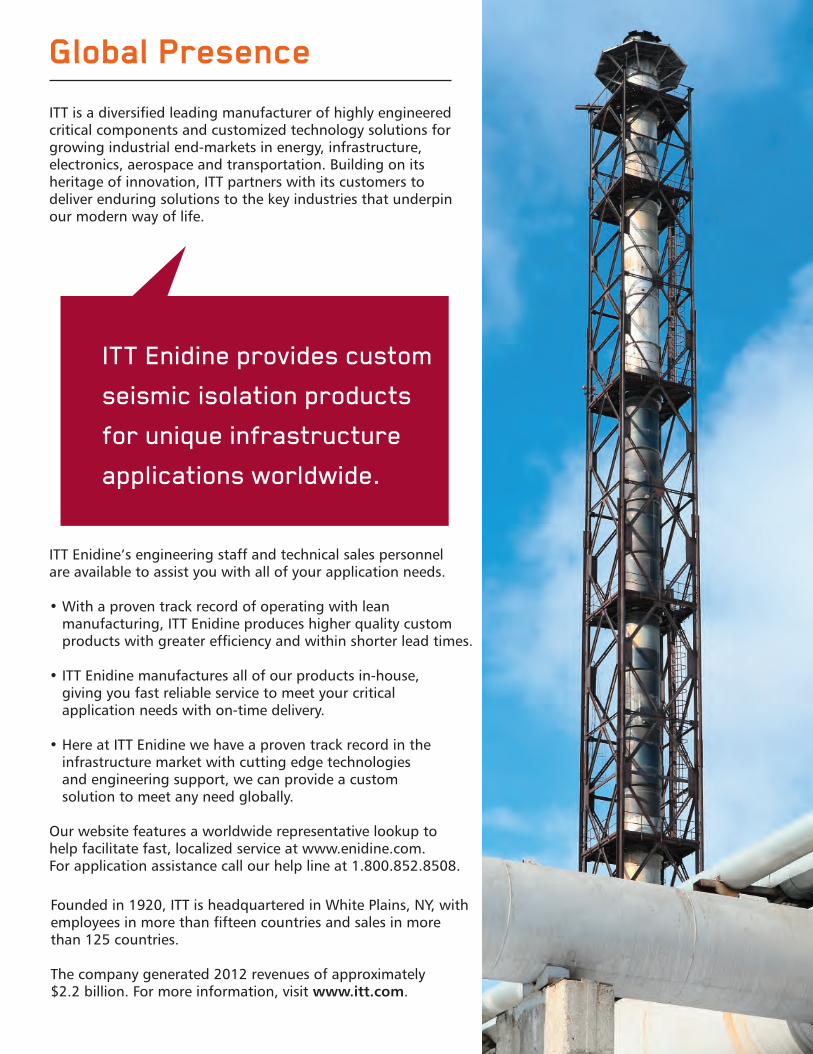
Global Presence
ITT Enidine provides custom
seismic isolation products
for unique infrastructure
applications worldwide.
ITT is a diversified leading manufacturer of highly engineeredcritical components and customized technology solutions forgrowing industrial end-markets in energy, infrastructure, electronics, aerospace and transportation. Building on its heritage of innovation, ITT partners with its customers to deliver enduring solutions to the key industries that underpinour modern way of life.
Founded in 1920, ITT is headquartered in White Plains, NY, withemployees in more than fifteen countries and sales in morethan 125 countries.
The company generated 2012 revenues of approximately $2.2 billion. For more information, visit www.itt.com.
ITT Enidine’s engineering staff and technical sales personnel are available to assist you with all of your application needs.
• With a proven track record of operating with lean manufacturing, ITT Enidine produces higher quality customproducts with greater efficiency and within shorter lead times.
• ITT Enidine manufactures all of our products in-house, giving you fast reliable service to meet your critical application needs with on-time delivery.
• Here at ITT Enidine we have a proven track record in the infrastructure market with cutting edge technologies and engineering support, we can provide a custom solution to meet any need globally.
Our website features a worldwide representative lookup to help facilitate fast, localized service at www.enidine.com. For application assistance call our help line at 1.800.852.8508.
Seismic_Products_Catalog:Seismic_Products_Catalog 7/13/16 11:05 AM Page 3
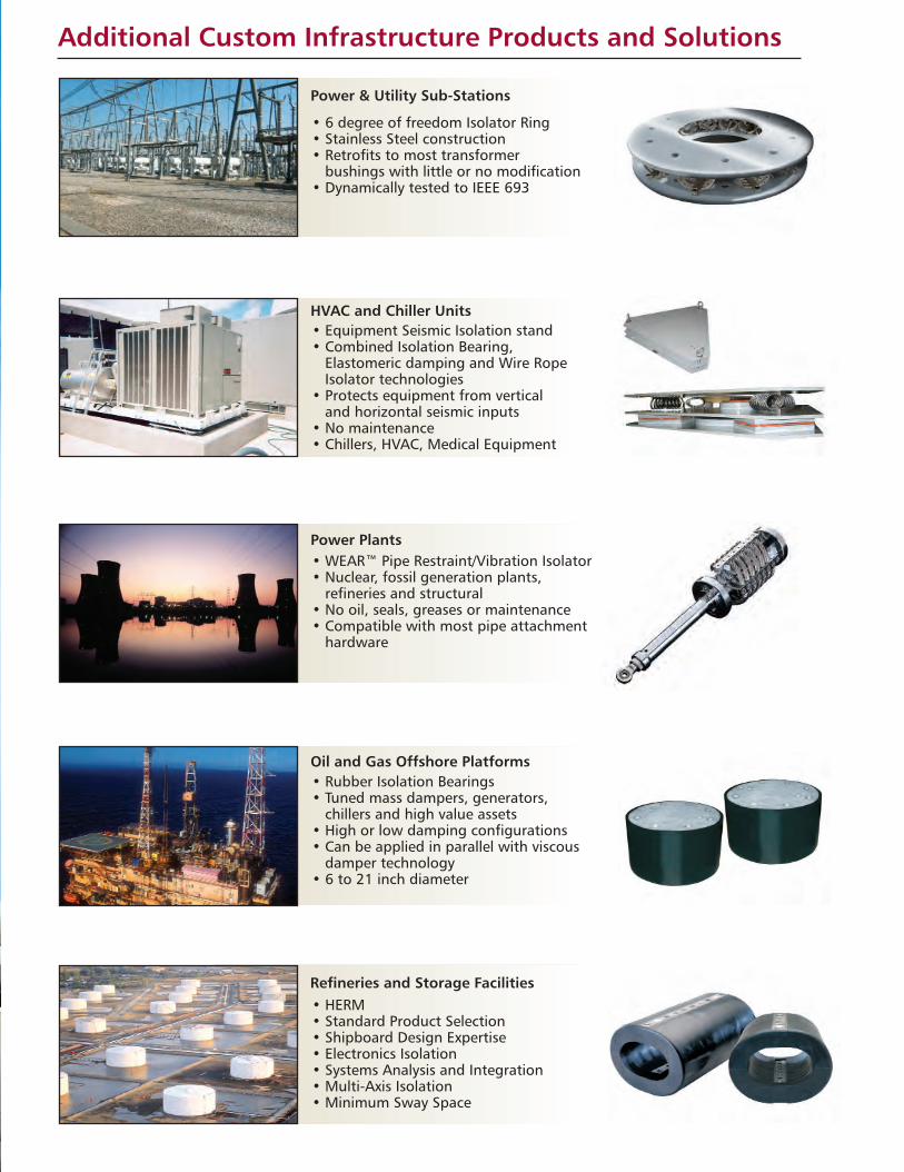
Additional Custom Infrastructure Products and Solutions
• 6 degree of freedom Isolator Ring• Stainless Steel construction• Retrofits to most transformer
bushings with little or no modification• Dynamically tested to IEEE 693
• WEAR™ Pipe Restraint/Vibration Isolator• Nuclear, fossil generation plants,
refineries and structural• No oil, seals, greases or maintenance• Compatible with most pipe attachment
hardware
• Rubber Isolation Bearings• Tuned mass dampers, generators,
chillers and high value assets• High or low damping configurations• Can be applied in parallel with viscous
damper technology• 6 to 21 inch diameter
• HERM• Standard Product Selection• Shipboard Design Expertise• Electronics Isolation• Systems Analysis and Integration• Multi-Axis Isolation• Minimum Sway Space
• Equipment Seismic Isolation stand• Combined Isolation Bearing,
Elastomeric damping and Wire RopeIsolator technologies
• Protects equipment from vertical and horizontal seismic inputs
• No maintenance• Chillers, HVAC, Medical Equipment
Power & Utility Sub-Stations
HVAC and Chiller Units
Power Plants
Oil and Gas Offshore Platforms
Refineries and Storage Facilities
Seismic_Products_Catalog:Seismic_Products_Catalog 7/13/16 11:05 AM Page 4

i
Infrastructure ProductsTable of Contents
Linear DampersLD-500 Series
Dimensional Data and Performance Curves..............................................................................................1
LD-700 SeriesDimensional Data and Performance Curves..............................................................................................2
LD-1100 SeriesDimensional Data and Performance Curves..............................................................................................3
LD-1500 SeriesDimensional Data and Performance Curves..............................................................................................4
Fluid Viscous DampersFVD-B Series
Dimensional Data ....................................................................................................................................5Performance Curves ................................................................................................................................6
FVD-H SeriesDimensional Data ....................................................................................................................................7Performance Curves ................................................................................................................................8
Applications and Capabilities........................................................................................................................9-10
How to Order ....................................................................................................................................................11
We Provide Highly Engineered CustomizedSolutions for EveryUnique Customer.
Seismic_Products_Catalog:Seismic_Products_Catalog 7/13/16 11:05 AM Page i
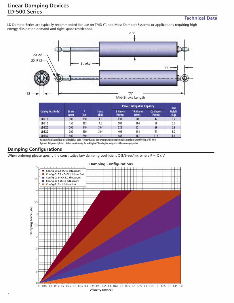
LD Damper Series are typically recommended for use on TMD (Tuned Mass Damper) Systems or applications requiring high energy dissipation demand and tight space restrictions.
*Maximum Force Reduced Due to Buckling Failure Mode. “Cylinder buckling load for cap pivot mounts determined in accordance with NFPA/T3.6.37 R1-2010, Hydraulic fluid power - Cylinders - Method for determining the buckling load.” Buckling load analyzed at mid-stroke damper position.
1
Linear Damping DevicesLD-500 Series
Technical Data
Power Dissipation Capacity
Damping ConfigurationsWhen ordering please specify the constitutive law damping coefficient C (kN–sec/m), where F = C x V
UnitCatalog No./Model Stroke A FMax. 3 Minutes 10 Minutes Continuous Weight
(mm) (mm) (kN) (Watts) (Watts) (Watts) (Kg)LD510 100 290 4.0 238 88 47 0.7LD515 150 365 4.0 280 104 58 0.8LD520 200 440 3.0* 322 121 69 0.9LD530 300 590 2.0* 402 154 91 1.2LD540 400 740 1.4* 482 187 112 1.4
ø38
2X R12
12
27Stroke
“A”Mid-Stroke Length
2X ø8
Seismic_Products_Catalog:Seismic_Products_Catalog 7/13/16 11:05 AM Page 1
2
Linear Damping DevicesLD-700 Series
Technical Data
Power Dissipation Capacity
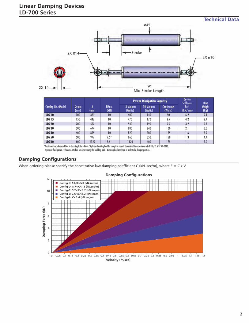
*Maximum Force Reduced Due to Buckling Failure Mode. “Cylinder buckling load for cap pivot mounts determined in accordance with NFPA/T3.6.37 R1-2010, Hydraulic fluid power - Cylinders - Method for determining the buckling load.” Buckling load analyzed at mid-stroke damper position.
DeviceStiffness Unit
Catalog No./Model Stroke A FMax. 3 Minutes 10 Minutes Continuous Ref. Weight(mm) (mm) (kN) (Watts) (Watts) (Watts) (kN/mm) (Kg)
LD710 100 371 10 400 140 50 6.2 2.1LD715 150 447 10 470 170 65 4.2 2.4LD720 200 522 10 540 190 75 3.2 2.7LD730 300 674 10 680 240 100 2.1 3.3LD740 400 825 10 820 300 125 1.6 3.9LD750 500 977 7.5* 960 350 150 1.3 4.4LD760 600 1129 5.5* 1120 400 175 1.1 5.0
Damping ConfigurationsWhen ordering please specify the constitutive law damping coefficient C (kN–sec/m), where F = C x V
ø45
2X ø102X R14
2X 14
Stroke
“A”MId-Stroke Length
Seismic_Products_Catalog:Seismic_Products_Catalog 7/13/16 11:05 AM Page 2
Linear Damping DevicesLD-1100 Series
Technical Data
Power Dissipation Capacity
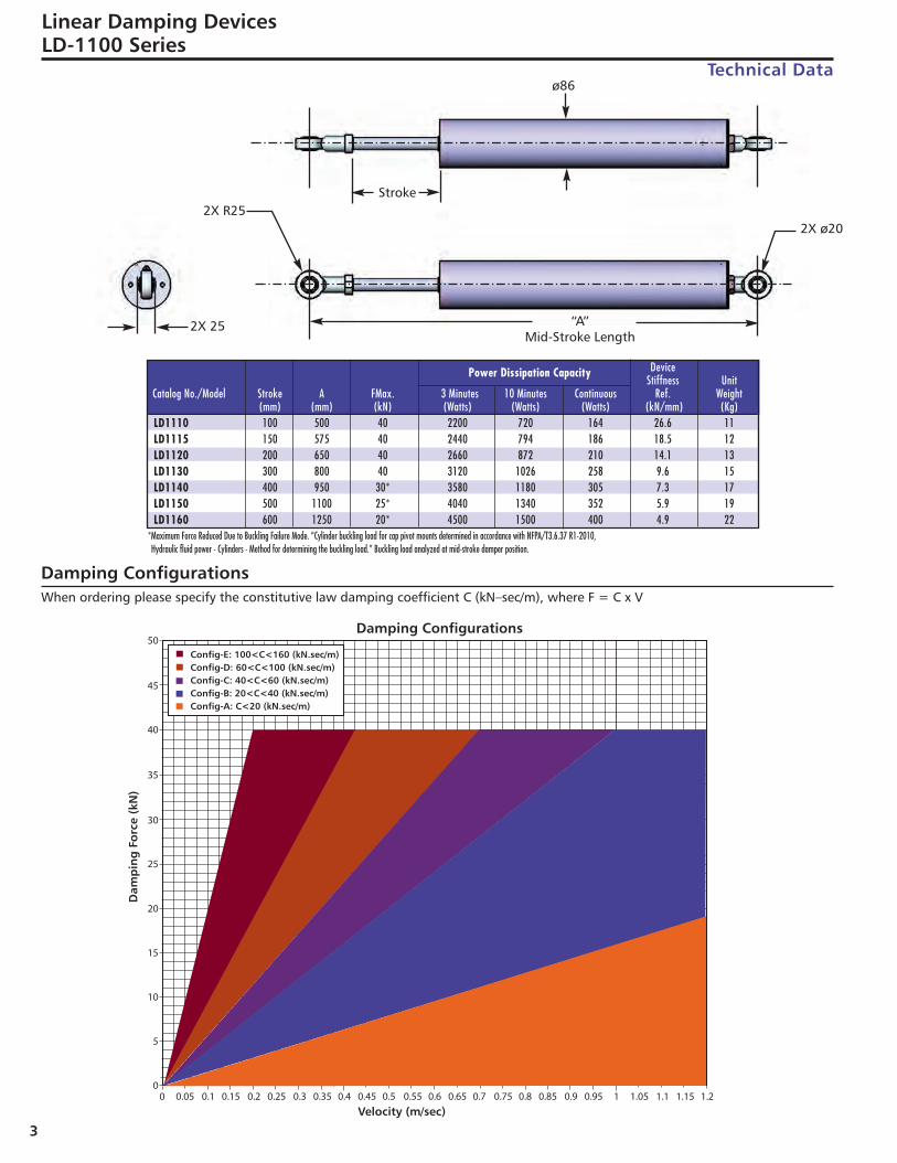
*Maximum Force Reduced Due to Buckling Failure Mode. “Cylinder buckling load for cap pivot mounts determined in accordance with NFPA/T3.6.37 R1-2010, Hydraulic fluid power - Cylinders - Method for determining the buckling load.” Buckling load analyzed at mid-stroke damper position.
DeviceStiffness Unit
Catalog No./Model Stroke A FMax. 3 Minutes 10 Minutes Continuous Ref. Weight(mm) (mm) (kN) (Watts) (Watts) (Watts) (kN/mm) (Kg)
LD1110 100 500 40 2200 720 164 26.6 11LD1115 150 575 40 2440 794 186 18.5 12LD1120 200 650 40 2660 872 210 14.1 13LD1130 300 800 40 3120 1026 258 9.6 15LD1140 400 950 30* 3580 1180 305 7.3 17LD1150 500 1100 25* 4040 1340 352 5.9 19LD1160 600 1250 20* 4500 1500 400 4.9 22
Damping ConfigurationsWhen ordering please specify the constitutive law damping coefficient C (kN–sec/m), where F = C x V
3
ø86
2X ø202X R25
2X 25
Stroke
“A”Mid-Stroke Length
Seismic_Products_Catalog:Seismic_Products_Catalog 7/13/16 11:05 AM Page 3
4
Linear Damping DevicesLD-1500 Series
Technical Data
Power Dissipation Capacity DeviceStiffness Unit
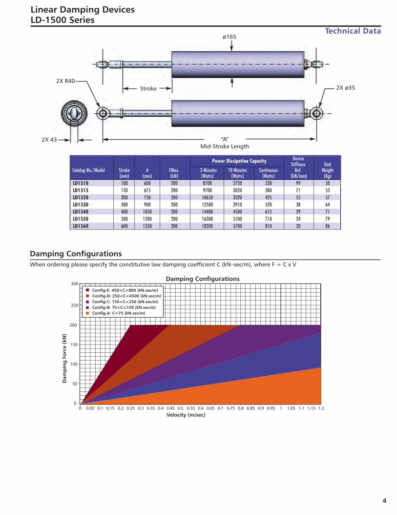
Catalog No./Model Stroke A FMax. 3 Minutes 10 Minutes Continuous Ref. Weight(mm) (mm) (kN) (Watts) (Watts) (Watts) (kN/mm) (Kg)
LD1510 100 600 200 8700 2720 330 99 50LD1515 150 675 200 9700 3020 380 71 53LD1520 200 750 200 10650 3320 425 55 57LD1530 300 900 200 12500 3910 520 38 64LD1540 400 1050 200 14400 4500 615 29 71LD1550 500 1200 200 16300 5100 710 24 79LD1560 600 1350 200 18200 5700 810 20 86
Damping ConfigurationsWhen ordering please specify the constitutive law damping coefficient C (kN–sec/m), where F = C x V
ø165
2X ø352X R40
2X 43
Stroke
“A”Mid-Stroke Length
Seismic_Products_Catalog:Seismic_Products_Catalog 7/13/16 11:05 AM Page 4
5
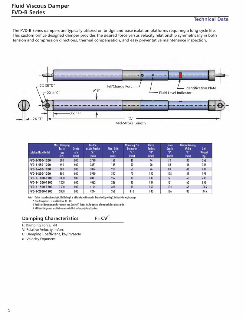
Fluid Viscous DamperFVD-B Series
Technical Data
Note: 1. Various stroke lengths available. Pin-Pin length at mid-stroke position can be determined by adding 2.5x the stroke length change.2. Velocity exponent α is available from 0.2 - 1.03. Weight and dimensions are for reference only. Consult ITT Enidine Inc. for detailed information before placing order.4. Additional designs and modifications are available based on project specifications.
Max. Damping Pin-Pin Mounting Pin Clevis Clevis Clevis/BearingForce Stroke at Mid-Stroke Max. O.D. Diameter Radius Depth Width Unit
Catalog No./Model FMCE ± S “A” “B” “C” “D” “E” “F” Weight(kN) (mm) (mm) (mm) (mm) (mm) (mm) (mm) (Kg)
FVD-B-300-1200 300 600 3790 166 40 74 70 35 262FVD-B-450-1200 450 600 3851 185 50 90 83 46 344FVD-B-600-1200 600 600 3874 210 50 96 83 46 437FVD-B-800-1200 800 600 3950 242 70 120 108 55 593FVD-B-1000-1200 1000 600 4011 267 80 130 121 60 735FVD-B-1200-1200 1200 600 4062 286 80 134 121 60 855FVD-B-1500-1200 1500 600 4124 318 90 150 134 65 1085FVD-B-2000-1200 2000 600 4244 356 110 180 166 80 1445
Damping Characteristics F=CVα
F: Damping Force, kNV: Relative Velocity, m/secC: Damping Coefficient, kN/(m/sec)αα: Velocity Exponent
2X SR”D”
2X ø”C”ø”B”
2X ”F”2X ”E”
“A”Mid-Stroke Length
Identification PlateFluid Level Indicator
Fill/Charge Port
The FVD-B Series dampers are typically utilized on bridge and base isolation platforms requiring a long cycle life. This custom orifice designed damper provides the desired force versus velocity relationship symmetrically in both tension and compression directions, thermal compensation, and easy preventative maintenance inspection.
Seismic_Products_Catalog:Seismic_Products_Catalog 7/13/16 11:05 AM Page 5
6
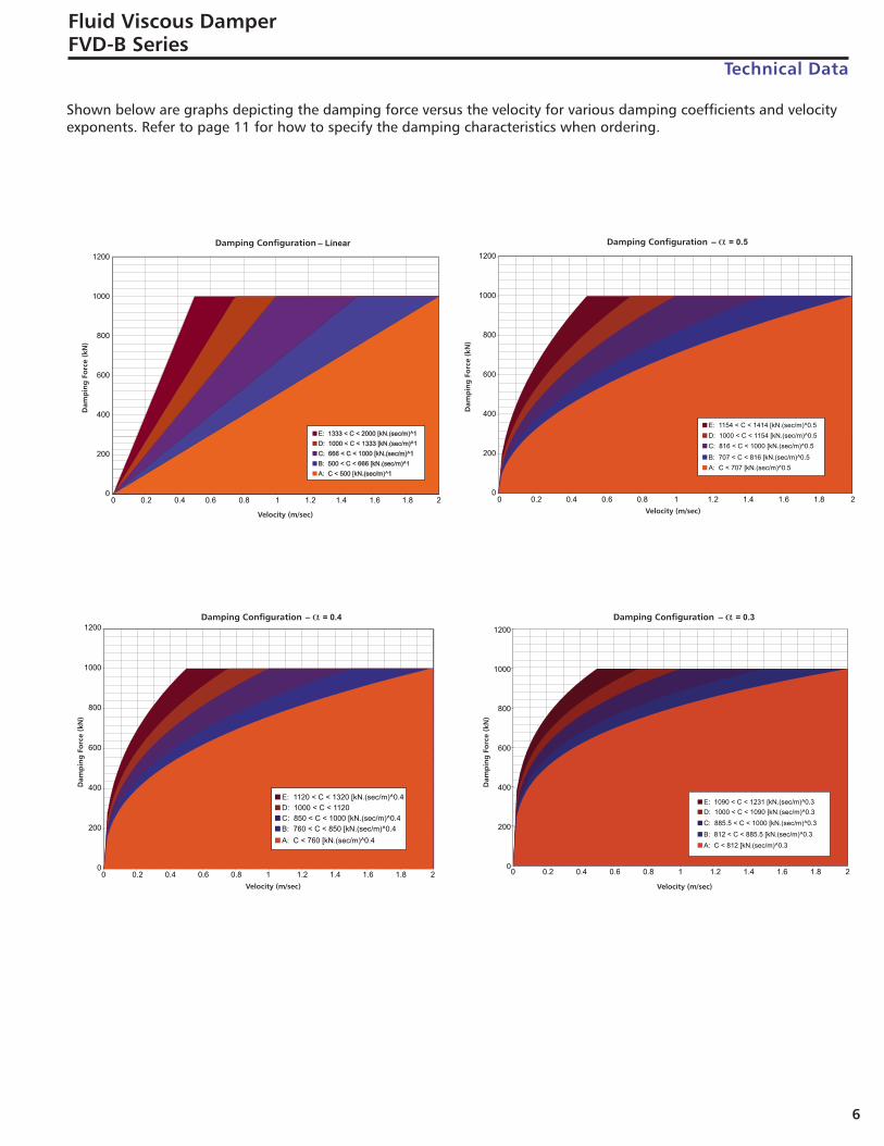
Fluid Viscous DamperFVD-B Series
Technical Data
Shown below are graphs depicting the damping force versus the velocity for various damping coefficients and velocityexponents. Refer to page 11 for how to specify the damping characteristics when ordering.
Seismic_Products_Catalog:Seismic_Products_Catalog 7/13/16 11:05 AM Page 6

7
Fluid Viscous DamperFVD-H Series
Technical Data
Note: 1. Various stroke lengths available. Pin-Pin length at mid-stroke position can be determined by adding 2.5x the stroke length change.2. Velocity exponent α is available from 0.2 - 1.03. Weight and dimensions are for reference only. Consult ITT Enidine Inc. for detailed information before placing order.4. Additional designs and modifications are available based on project specifications.
Max. Damping Pin-Pin Mounting Pin Clevis Clevis Clevis/BearingForce Stroke at Mid-Stroke Max. O.D. Diameter Radius Depth Width Unit
Catalog No./Model FMCE ± S “A” “B” “C” “D” “E” “F” Weight(kN) (mm) (mm) (mm) (mm) (mm) (mm) (mm) (Kg)
FVD-H-500-150 500 75 969 147 51 70 89 48 80FVD-H-750-150 750 75 1020 178 64 86 112 58 125FVD-H-1000-150 1000 75 1070 201 77 104 134 67 173FVD-H-1500-150 1500 75 1140 248 89 120 156 77 274FVD-H-2000-150 2000 75 1210 286 102 135 178 86 385
Damping Characteristics F=CVα
F: Damping Force, kNV: Relative Velocity, m/secC: Damping Coefficient, kN/(m/sec)αα: Velocity Exponent
“A”MId-Stroke Length
ø”B”
ø”C”
R”D”
“F”
“E”
The FVD-H Series dampers are typically utilized on building applications, mounted indoors, where the damper is not under constant vibration or movement.
Seismic_Products_Catalog:Seismic_Products_Catalog 7/13/16 11:05 AM Page 7
8
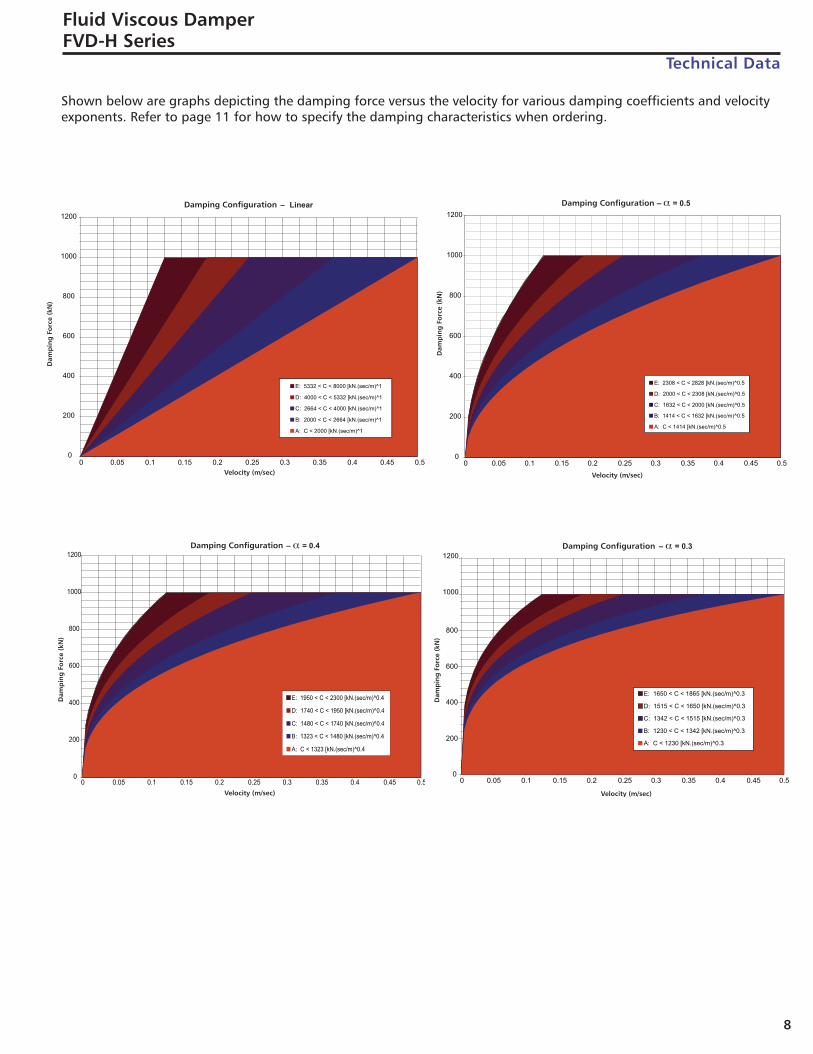
Fluid Viscous DamperFVD-H Series
Technical Data
Shown below are graphs depicting the damping force versus the velocity for various damping coefficients and velocityexponents. Refer to page 11 for how to specify the damping characteristics when ordering.
Seismic_Products_Catalog:Seismic_Products_Catalog 7/13/16 11:05 AM Page 8
9
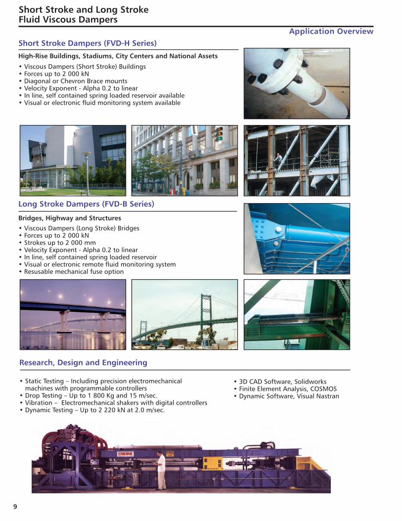
• Viscous Dampers (Short Stroke) Buildings• Forces up to 2 000 kN• Diagonal or Chevron Brace mounts• Velocity Exponent - Alpha 0.2 to linear• In line, self contained spring loaded reservoir available• Visual or electronic fluid monitoring system available
Short Stroke Dampers (FVD-H Series)
• Viscous Dampers (Long Stroke) Bridges• Forces up to 2 000 kN• Strokes up to 2 000 mm• Velocity Exponent - Alpha 0.2 to linear• In line, self contained spring loaded reservoir• Visual or electronic remote fluid monitoring system• Resusable mechanical fuse option
Long Stroke Dampers (FVD-B Series)
• Static Testing – Including precision electromechanical machines with programmable controllers
• Drop Testing – Up to 1 800 Kg and 15 m/sec.• Vibration – Electromechanical shakers with digital controllers• Dynamic Testing – Up to 2 220 kN at 2.0 m/sec.
Research, Design and Engineering
• 3D CAD Software, Solidworks• Finite Element Analysis, COSMOS• Dynamic Software, Visual Nastran
High-Rise Buildings, Stadiums, City Centers and National Assets
Bridges, Highway and Structures
Short Stroke and Long Stroke Fluid Viscous Dampers
Application Overview
Seismic_Products_Catalog:Seismic_Products_Catalog 7/13/16 11:05 AM Page 9
10
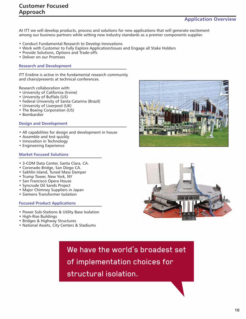
At ITT we will develop products, process and solutions for new applications that will generate excitementamong our business partners while setting new industry standards as a premier components supplier.
• Conduct Fundamental Research to Develop Innovations• Work with Customer to Fully Explore Application/Issues and Engage all Stake Holders• Provide Solutions, Options and Trade-offs• Deliver on our Promises
Research and Development
ITT Enidine is active in the fundamental research community and chairs/presents at technical conferences.
Research collaboration with:• University of California (Irvine)• University of Buffalo (US)• Federal University of Santa Catarina (Brazil) • University of Liverpool (UK)• The Boeing Corporation (US)• Bombardier
Design and Development
• All capabilities for design and development in house• Assemble and test quickly• Innovation in Technology• Engineering Experience
Market Focused Solutions
• 3-COM Data Center, Santa Clara, CA.• Coronado Bridge, San Diego CA.• Sakhlin Island, Tuned Mass Damper• Trump Tower, New York, NY• San Francisco Opera House• Syncrude Oil Sands Project• Major Chimney Suppliers in Japan• Siemens Transformer Isolation
Focused Product Applications
• Power Sub-Stations & Utility Base Isolation• High-Rise Buildings• Bridges & Highway Structures• National Assets, City Centers & Stadiums
We have the world’s broadest set
of implementation choices for
structural isolation.
Customer Focused Approach
Application Overview
Seismic_Products_Catalog:Seismic_Products_Catalog 7/13/16 11:05 AM Page 10
11
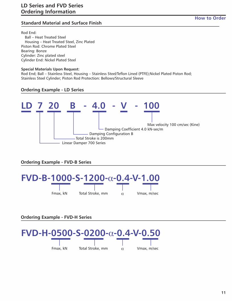
LD Series and FVD SeriesOrdering Information
How to OrderStandard Material and Surface Finish
Rod End:Ball – Heat Treated SteelHousing – Heat Treated Steel, Zinc Plated
Piston Rod: Chrome Plated SteelBearing: BonzeCylinder: Zinc plated steelCylinder End: Nickel Plated Steel
Special Materials Upon Request:Rod End; Ball – Stainless Steel, Housing – Stainless Steel/Teflon Lined (PTFE);Nickel Plated Piston Rod;Stainless Steel Cylinder; Piston Rod Protection: Bellows/Structural Sleeve
LD 7 20 B - 4.0 - V - 100
Max velocity 100 cm/sec (Kine)Damping Coefficient 4.0 kN-sec/m
Damping Configuration BTotal Stroke is 200mm
Linear Damper 700 Series
Ordering Example - LD Series
FVD-H-0500-S-0200-α-0.4-V-0.50Fmax, kN Total Stroke, mm Vmax, m/secα
Ordering Example - FVD-H Series
FVD-B-1000-S-1200-α-0.4-V-1.00Fmax, kN Total Stroke, mm Vmax, m/secα
Ordering Example - FVD-B Series
Seismic_Products_Catalog:Seismic_Products_Catalog 7/13/16 11:05 AM Page 11

IND1036R1 7/13 1M
ITT Enidine Inc.7 Centre DriveOrchard Park, New York 14127Phone: 716-662-1900Fax: 716-667-1385Email: [email protected]
Seismic_Products_Catalog:Seismic_Products_Catalog 7/13/16 11:05 AM Page 1