Embed Size (px)
Citation preview

Research ArticleSeismic Performance of Steel Frames withSemirigid Connections
Iman Faridmehr1 MahmoodMd Tahir1 Tom Lahmer2 andMohd Hanim Osman3
1UTM Construction Research Centre (CRC) Institute of Smart Infrastructures and Innovative ConstructionUniversiti Teknologi Malaysia (UTM) 81300 Skudai Johor Malaysia2Institute of Structural Mechanics-Structural Analysis and Component Strength Bauhaus University Weimar Germany3Forensic Engineering Centre (FEC) Universiti Teknologi Malaysia (UTM) 81300 Skudai Johor Malaysia
Correspondence should be addressed to Mahmood Md Tahir mahmoodtahirutmmy
Received 2 August 2016 Revised 12 November 2016 Accepted 9 January 2017 Published 30 April 2017
Academic Editor Kyoung Kwan Ahn
Copyright copy 2017 Iman Faridmehr et alThis is an open access article distributed under theCreativeCommonsAttributionLicensewhich permits unrestricted use distribution and reproduction in any medium provided the original work is properly cited
The nonlinear stiffness matrix method was incorporated to investigate the structural performance of steel portal frames with semi-rigid connections A portal frame with unstiffened extended end-plate connection was designed to demonstrate the adequacy ofthe proposedmethod Besides the seismic performance of steel portal frames with semirigid connections was investigated throughtime history analysis where kinematic hysteresis model was assigned to semirigid connections to account for energy dissipationand unloading stiffness Based on the results of the study it was found that generally semirigid connections influenced the forcedistribution which resulted in the decrease in base shear and lighter frame compared to the rigid one The results also indicatedthat there was no direct relationship between maximum displacement at the top and connection stiffness in high-rise frames
1 Introduction
The structural behaviour of steel portal frame is mainly asso-ciated based on its connectionrsquos performance Accordinglythe accurate modelling of steel portal frame needs to takeinto account realistic connection modelling if an accurateresponse is desired to be achieved It is a usual engineeringpractice to consider either perfect simple or fully rigidconnections between beam and column Experimental testshowever have acknowledged the real behaviour of beam-to-column connections in someplace between these two unreal-istic models that possess remarkable flexibility Based on themajority of design regulations it is only necessary to considerthe connection flexibility for the third category however it ispredicted that majority of beam to column connection typeshave semirigid performance in some fashion
The rigidity of beam-to-column connections have rela-tionship with geometrical factors of the connection com-ponents that is angle section bolts size and end-plateWidespread research projects that consist of numerical andexperimental tests have been done so far to demonstratemoment-rotation relationship which is suitable to estimate
the ideal behaviour of semirigid connections [1ndash6] Based onthe results of the above studies which differ from linearmodelto power and polynomial models a large and growing num-ber of literatures has investigated the seismic performanceof steel portal frames with semirigid connections [7ndash11] Thefindings of these studies suggested that adequately designedsemirigid beam-to-column connections and frames shouldbe associated with ductile and steady hysteretic performanceThe results also revealed that there was a direct relationshipbetween connection stiffness and base shear however thelateral drift did not decrease linearly by increasing the con-nection stiffness It was also highlighted that ideal structureshould incorporate the least probable base shear reactionwithsatisfactory lateral sway Many researchers have investigatedanalytically the seismic behaviour of semirigid frames [12ndash15] The results give evidence that there was a substantialpotential to use semirigid structureswhose seismic behaviouris similar to that of rigid one mainly in moderate seismicareas Moreover the semirigid frames possess benefit oflonger first mode period and therefore attract smaller inertialloads This issue compensates the effect of the enlargedflexibility
HindawiJournal of EngineeringVolume 2017 Article ID 5284247 10 pageshttpsdoiorg10115520175284247
2 Journal of Engineering
PR
FR
Simple
003
Mom
entM
Rotation 휃 (radians)
Mp beam
Mn
Mn
Mn
휃u
휃u
휃u
휃s
휃s
휃s
Ks =20EI
LM(휃)
Ks =2EI
L
Figure 1 Moment-rotation curves for connections [16]
It appears from the aforementioned investigations thatnumerous researches have studied the effects of frames withsemirigid connections However far too little attention hasbeen paid to the hysteresis modelling of semirigid con-nections to account for decreasing energy dissipation andunloading stiffness with increasing plastic deformation Thepresent study explores the influence of semirigid connectionon structural performance of steel portal frame throughanalytical study The seismic performance of steel portalframes also was investigated through nonlinear time historyanalysis where kinematic hysteresis model was assignedto semirigid connections to consider energy dissipationcapacity and stiffness degradation The required parametersfor the above-mentioned hysteresis models were extractedfrom eight full-scale experimental tests results of unstiff-ened extended end-plate connections conducted at UniversitiTeknologi Malaysia
2 AISC and Eurocode Classification ofBeam-to-Column Connections
According to the AISC the beam-to-column connection isclassified based on the characteristics of moment-rotation(M-120579) curve It covers strength stiffness and ductility ofthe beam-to-column connections The secant stiffness 119870119904at service loads is a fundamental criterion of the connectionstiffness as defined in
119870119904 = 119872119904120579119904 (1)
where119872119904 ismoment at service load (kN-m) and 120579119904 is rotationat service load rad
If 119896119904119871119864119868 ge 20 the connection is considered to be fullyrigid or FR connections (able to preserve the rotation betweenmembers) If 119896119904119871119864119868 le 2 the connection is classified assimple (it rotates without increasing moment) The connec-tion stiffness between these two boundaries is categorizedas a partially restrained ldquoPRrdquo or semirigid connection (seeFigure 1) and the strength ductility and stiffness of thebeam-to-column connections should be taken into accountin the analysis process
Themaximummoment can be carried out by connectionintroduced as119872119899 as shown in Figure 1 Connections with alesser amount of 20 of the plastic moment of the connectedbeam119872119901 at a the rotation of 002 rad are supposed to haveno flexural capacity for analysis It is worth mentioning thatfor FR connection strength less than the beam strength isanticipated Yet it is also probable for a PR connection toprovide a moment capacity higher than the connected beam[6]
In Eurocode 3 Part 1ndash8 [17] the classification of beam-to-column joint may be classified as rigid nominally pinned orsemirigid by comparing its initial rotational stiffness 119878119895iniwith connected beam stiffness The connections that arecategorized as fully rigid are supposed to have an adequaterotational stiffness to consider analyses based on fully rigidThe following equation represents rigid connection bound-aries
119878119895ini ge 119870119887119864119868119887119871119887 (2)
where119870119887 is taken as 8 for fully rigid structures119870119887 is taken as25 for other frames 119868119887 is moment inertia of connected beamand 119871119887 is the length of connected beam
A supposedly simple connection should be capable oftransferring the external forces without increasing sub-stantial moments that influence adversely members or thestructure as a whole According to Eurocode 3 Part 1ndash8 theconnections are considered as nominally pinned if
119878119895ini le 05119864119868119887119871119887 (3)
The beam-to-column connections that do not address thecriteria for FR connections or a simple connections shall beclassified as partially restrained (PR) or semirigid connec-tions PR connections provide an anticipated deformationbetween connected members based on the (M-120579) curvefeatures of the connections PR connections are supposedto convey the shear forces as well as bending momentsThe initial stiffness 119878119895ini of beam-to-column connectionsis determined through flexibility of its main elements eachelement is characterized by an elastic stiffness coefficient 119896119894The initial rotational stiffness 119878119895ini of a beam-to-columnconnection calculated with an accuracy from following equa-tion is recommended by Eurocode 3 Part 1ndash8 [17]
119878119895 = 1198641199112120583sum119894 (1119896119894)
(4)
where 119896119894 is the stiffness coefficient for basic joint component119894 z is the lever arm of extended end-plate connection and 120583is the stiffness ratio (119878119895ini119878119895)
3 Performance of Portal Frameswith Semirigid Connections UsingAnalytical Method
Analysis of semirigid frames requires accurately predictingthe connectionrsquos performance Nonlinear behaviour of con-nections through moment-rotation curve and some of the
Journal of Engineering 3
A
L
iE
A I
B
Y
X
Ka
Kb
VAB YAB
PAB XAB
MAB 휃AB
훼
VBA YBA
PBA XBAMBA 휃BA
(a)
A
L
i
B
X
Y
휃RA
휃BA
휃RB
휃AB
MBA
MAB
(b)
Figure 2 (a) Forces and displacements and (b) rotations in the semirigid frame component
analytical method are used to predict them This analyti-cal method is defined as the moment-rotation relationshipachieved by a decent curve to full-scale experimental testresults One of the most famous methods which is used inthis study is suggested by Frye and Morris This method ischaracterized through an odd power polynomial as
120579119903 = 1198881 (119870119872)1 + 1198882 (119870119872)3 + 1198883 (119870119872)5 (5)
where 120579119903 is the rotation of connection 119872 is the appliedmoment to connection K is the normalized parameter rela-tion between connection category and geometry and 1198881 1198882and 1198883 are defined as the moment-rotation curve parameters
Chen and Lui [18] provide the value of these parametersfor different type of connectionsThe flexibility of connectionis obtained as follows
119878 = 119889119872119889120579 = 1
1198881119870 + 31198882 (119870119872)2 + 51198883 (119870119872)4 (6)
The initial stiffness was to be considered whenever theconnection is unloaded and calculated as
119878 = 119889119872119889120579 = 1
1198881119870 (7)
Themain drawback of this formulation is that the tangentconnection stiffness may become negative at some valueof connection moment 119872 This is physically unacceptableand the negative stiffness may cause numerical difficultiesin the analysis of frame structures if the tangent stiffnessformulation is used Following the procedure of Frye-Morris(1975) Picard et al (1976) and Altman et al (1982) developedprediction equations to describe the Mndash120579r curve for strap-angle connections and top- and seat-angle connection withdouble web angles respectively Goverdhan (1983) reesti-mated the size parameters in the standardization constant 119870for flush end-plate connections to get a good agreement withmoment-rotation curves obtained from experimental results
31 Nonlinear StiffnessMatrix of Beamwith Semirigid Connec-tions During the analysis of steel portal framewith semirigid
beam-to-column connections the influence of connectionflexibility is considered through assigning rotational jointpossessing stiffness 119870119886 and 119870119887 to both ends of component asshown in Figure 2
The nonlinear stiffness matrix of component 119894 withconsidering internal axial force and semirigidity connectionsat both ends in global system has the following form
[119878] =
10038161003816100381610038161003816100381610038161003816100381610038161003816100381610038161003816100381610038161003816100381610038161003816100381610038161003816100381610038161003816100381610038161003816
119886119887 119889 1198781198841198721198881 1198901 1198911minus119886 minus119887 minus1198881 119886minus119887 minus119889 minus1198901 119887 119889minus1198882 minus1198902 1198912 1198882 1198902 119892
10038161003816100381610038161003816100381610038161003816100381610038161003816100381610038161003816100381610038161003816100381610038161003816100381610038161003816100381610038161003816100381610038161003816
(8)
where
119886 = 119864119860119871 times cos2120572 + 12119864119868
1198713 times 1198911199091 times 05 times sin2120572
119887 = (119864119860119871 minus 121198641198681198713 times 1198911199091 times 05) cos120572 sin120572
119889 = 119864119860119871 times sin2120572 + 12119864119868
1198713 times 1198911199091 times 05 times cos2120572
1198881 = minus61198641198681198712 times 1198911199092 times 02 times sin120572
1198882 = minus61198641198681198712 times 1198911199093 times 02 times sin120572
1198911 = 4119864119868119871 times 1198911199094 times 03
1198912 = 2119864119868119871 times 1198911199095 times 03
1198901 = minus61198641198681198712 times 1198911199092 times 02 times cos120572
1198902 = minus61198641198681198712 times 1198911199093 times 02 times cos120572
119892 = 4119864119868119871 times 1198911199096 times 04
(9)
4 Journal of Engineering
where 119864 is module of elasticity 119871 119868 119860 and 120572 are the lengthmoment of inertia area and cosine direction of the elementrespectively The influence of the connection flexibility isconsidered in thematrix by adapting the stiffness expressionsof fully rigid component through the following equations[19]
1198911199091 = (119870119886 times 119870119887 + 119870119886 + 119870119887)119870119870
1198911199092 = 119870119886 (119870119887 + 2)119870119870
1198911199093 = 119870119887 (119870119886 + 2)119870119870
1198911199094 = 119870119886 (119870119887 + 3)119870119870
1198911199095 = 119896119886 times 119870119887119870119870
1198911199096 = 119870119887 (119870119886 + 3)119870119870
119870119870 = 119870119886119870119887 + 4 (119870119886 + 119870119887) + 12
(10)
where 119870119886 and 119870119887 are the stiffness of flexible connectionsat two ends of the component This rotational stiffness iscalculated as tangent stiffness through nonlinear parametergiven in (5)The influences of axial forces are incorporated inthe nonlinear matrix through considering functions of 01 0203 04 and 05 as follows [20]
01 = 120573 cot120573
02 = 1205732(3 minus 301)
03 = 302 + 014
04 = 302 minus 012
05 = 0102
(11)
where
120573 = 05120587radic120588
120588 = 1198651119875cr =
11986511198972(1205872119864119868)
(12)
In the above equations 1198651 is the axial force in the compo-nent and 119875cr is the Euler critical load of hinge-ended elementwith identical geometry and stiffness of the component Bycalculating stiffness matrix for each individual componentsthe global stiffness matrix which incorporated the effectsof large deformations and flexibility of connections can becalculated This process is nonlinear and requires iterativeanalysis Accordingly applied loads are divided into some
P
Pa
Pnri
xi xi+1X
Δu
휏i
Figure 3 Newton-Raphson solution one iteration
smaller parts and stiffness matrix equations are consideredas incremental load as follows
Δ119875 = [120591] Δ119883 (13)
where [120591] = sum119898119894=1[119878]119894 is the stiffness matrix of wholestructure Δ119875 is the incremental force vector and Δ119883 isthe incremental displacement vector
By using (13) the quantity of Δ119883 in each stage can becalculated However as long as the component and connec-tion stiffness are considered constant during the analysisthe structure equilibrium equations cannot be satisfied Toaddress this problem Newtown-Raphson force vector areapplied to (13) in each stage The Newton-Raphson methodis an iterative process of solving the nonlinear equations andcan be written as
[120591119879119894 ] Δ119909119894 = 119875119886 minus 119875119899119903119894 (14)
119909119894+1 = 119909119894 + Δ119909119894 (15)
where [120591119879119894 ] is Jacobian matrix 119894 is subscript representing thecurrent equilibrium iteration and 119875119899119903119894 is vector of restoringloads corresponding to the element internal loads
As can be seen in Figure 3 more than one Newton-Raphson iteration is needed to obtain a converged solutionThe general algorithm proceeds as follows
1 Assume 1199090 1199090 is usually the converged solutionfrom the previous time step On the first time step1199090 = 0
2 Compute the updated tangent matrix [120591119879119894 ] and therestoring load 119875119899119903119894 from configuration 119909119894
3 Calculate Δ119909119894 from (14)
4 Add Δ119909119894 to 119909119894 in order to obtain the next approxi-mation 119909119894+1 (15)
5 Repeat steps (2) to (4) until convergence is obtained
Journal of Engineering 5
3 3
2 25
6
41 1
7 7
77
7 73558kN
3558kN
1779kN
0377kNcm
0377kNcm 0377kNcm
0377kNcm
0306kNcm 0306kNcm
6096 cm
365776 cm
365776 cm
6096 cm
365776 cm
Figure 4 Unbraced steel portal frame with semirigid connections [21]
Optionalshear row
200
90 5555
504060
906025
Leve
r arm
Verticalshear
8
10
10
M
tp
(Fr1)(Fr2)
sumFr
l
Figure 5 Unstiffened extended end-plate connection as partial strength connections
32 Design Example To show the adequacy of suggestedmethod the moment steel portal frame having semirigidconnections was considered as shown in Figure 4 alreadystudied by Kameshki and Saka [21]
The proposed connections are designed using unstiffenedextended end-plate as shown in Figure 5 The required curvefitting and constant parameters for moment-rotation curveare given in (5) and considered as follows [18] (all sizeparameters are in inches)
1198881 = 183 times 10minus3
1198882 = minus104 times 10minus4
1198883 = 638 times 10minus6
119896 = 119889119892minus24119905119901minus04119889119887minus15
(16)
where 119889119892 is lever arm 119905119901 is thickness of end-plate and 119889119887is the diameter of the bolts In this example the thickness ofend-plate is considered as 12mmThe value of lever arm has arelationship with the connected beam depthThe bolt diame-ter was designed in accordance with British standard BS5950for bending moment and shear consideration By using thisinformation (5) can determine the stiffness of semirigid con-nection for different value of moment American wide flangesectionswith grade steel of A36were used for both beams andcolumns The modulus of elasticity is 210 times 106 kNm2
To show the effects of semirigid connections on structuralperformance the analyses of portal frame with rigid con-nections were also considered Both steel frames design wasperformed in accordance with the 2010 AISC direct analysismethod (AISC 360-10IBC 2006) The results of both framesare summarized and given in Table 1 It is apparent from
6 Journal of Engineering
Table 1 Structural performance of frame with semirigid and rigidconnections [21]
Componentnumber Component type Rigid-frame Semirigid frame
1 Column W24 times 68 W21 times 732 Column W21 times 73 W21 times 733 Column W18 times 40 W6 times 154 Column W21 times 50 W24 times 685 Column W16 times 36 W18 times 356 Column W12 times 40 W18 times 357 Beam W18 times 35 W16 times 26Total weight(kg) 457400 393810
Top storeydisplacement(cm)
096 120
Maximuminterstorey drift 048 052
Table 2 Sectional properties of 5- 10- and 15-storey frames
Storey 5-storey frame 10-storey frame 15-storey frameColumn section
1ndash3 W12 times 87 W27 times 102 W33 times 1524ndash6 W12 times 19 W24 times 68 W30 times 1487ndash9 mdash W24 times 55 W24 times 8410ndash12 mdash W14 times 22 W21 times 7313ndash15 mdash W16 times 57
Beam section1ndash3 W14 times 38 W14 times 48 W14 times 534ndash6 W14 times 34 W14 times 48 W14 times 537ndash9 mdash W14 times 48 W14 times 4810ndash12 mdash W12 times 40 W12 times 4013ndash15 mdash W10 times 39
Table 1 that frame having semirigid connections is around11 percent lighter compared to the rigid one However itexperienced 25 percent more lateral displacement
4 Performance of Portal Frames withSemirigid Connections Using NonlinearTime History Analysis
41 Description of Specimens To evaluate the connectionsemirigidity effects on steel portal frames subjected to theground acceleration 5- 10- and 15-storey frames were con-sidered as shown in Figure 6 The frames were considered asresidential buildings and designed according to AISC directanalysis method (AISC 360-10IBC 2006) The 5KNm and2KNm were assigned to the beams representative of deadand live load respectivelyTheWsectionswere used for beamand column in all three frames as shown in Table 2
For each analysis kinematic hysteresis models alongwith individual stiffness were assigned to the connectionsThe stiffness was calculated from 6 full-scale experimentaltests of flush end-plate connection with variable parametersincluding number of bolt rows thickness of end-plate andbolts size A test rig was considered to accommodate a 3mheight column and a 13m span of cantilever beam as shownin Figure 7 A hydraulic jack is applied the concentrated loadat the tip of connected beam The loading of the specimenwas performed using 5 kN increments until the occurrenceof a substantial deflection in the beam A series of tensiletests were conducted on the web and flange of columnbeam and end-plate of the specimen The average value ofyield and ultimate strengthwere 338Nmm2 and 502Nmm2respectively
The moment-rotation curves for all the six beam-to-column connections are shown in Figure 8 In all the tests thespecimens experienced linear behaviour in the first stage andthen are followed by nonlinear behaviour slowly droppingthe stiffness by increasing the rotation It is mainly due tothe concentrated deformation appearing at the tension regionof the connections through the top bolt rows as shown inFigure 9
The results of the initial stiffness moment capacity andmaximum rotation for all the six beam-to-column con-nections are given in Table 3 The rotation stiffness of theconnection depends on the geometrical configuration of theconnection Generally the higher the moment resistance ofthe connection the stiffer the connectionrsquos stiffness Howeverfactor such as number of bolts thickness of the plate anddepth of the beam play an important role to determinethe stiffness of the connection Therefore it is the bestway to represent the rotation stiffness of the connectionby comparing the moment resistance and relate to otherconnectionrsquos parameters
42 Hysteresis Models Hysteresis is the process of energydissipation through deformation (displacement) that affectsnonlinear static andnonlinear timehistory load cases Severaldifferent hysteresis models are available to describe thebehaviour of different types of materials For the most partthese differ in the amount of energy they dissipate in agiven cycle of deformation and how the energy dissipationbehaviour changes with an increasing amount of deforma-tion Typical for all models cyclic loading behaves as follows
(i) Initial loading in the positive or negative directionfollows the backbone curve
(ii) During the reversal deformation unloading occursalong a different path usually steeper than the loadingpath
(iii) After the load level is reduced to zero continuedreversal of deformation causes reverse loading along apath that eventually joins the back bone curve on theopposite side
Figure 9 shows kinematic hysteresis model It is basedupon the kinematic hardening behaviour that is commonlyobserved in metals and it is the default hysteresis model for
Journal of Engineering 7
33
33
3
5 5 53
33
33
5 5 5
33
33
3
33
33
33
33
33
33
33
3
5 5 5
Figure 6 5- 10- and 15-storey portal frames
LoadHydraulic
Restrained system
Jack
Connection
Beam
Column
Base plate
Bracing
Strong Floor
Roller
Figure 7 Test rig for full-scale testing
allmetalmaterialsThismodel dissipates a significant amountof energy and is appropriate for ductile materials Under therules of kinematic hardening the plastic deformation occursin one direction and ldquopullsrdquo the curve in the other direction
43 Earthquake Ground Motions To perform nonlineardynamic analysis it is crucial to select earthquake recordsproportional to the geotechnical properties and soil condi-tions of the site In this research the intended frames have
been designed on rock beds of soil site class B in compliancewith response spectrum of IBC 2009 code Accordingly10 ground motion records were considered from PacificEarthquake Engineering Research Center (PEER) as given inTable 4
44 Results and Discussion Figures 11 to 13 show thebase shear versus displacement for 5- 10- and 15-storeyframes respectivelyThe analyseswere accomplished through
8 Journal of Engineering
Mom
ent (
kNmiddotm
)0
50
100
150
200
250
300
350
20 40 60 80 100 1200Rotation (mrad)
FEP 6FEP 5FEP 4
FEP 3FEP 1FEP 2
Figure 8 Moment-rotation curves of flush end-plate connections
Figure 9 Failure mode at the end of the test
Actio
n
Deformation
Figure 10 Kinematic hysteresis model
displacement controlled and incremental lateral loads wereapplied on frames having fully rigid beam-to-column con-nections The pushover analyses were carried out and mono-tonically increased till the 15 times target displacement wasreached The triangular pattern of loading was applied to theframes and plastic hinge rotation angle was the main param-eter to identify the performance level (immediate occupancylife safety and collapse prevention)The equivalent base shearand maximum displacement at the top for boundary states(immediate occupancy life safety and collapse prevention)
are demonstrated on the capacity curves for all frames whereit shows the life safety requirement satisfied
To study the seismic performance of the semirigid andfully rigid frames the time history analyses were comparedwith pushover analysis As can be seen in the Figures 11 to13 the maximum base shear in the time history analyseswas greater than the amount determined from the pushoveranalyses Generally when the connection stiffness decreasedthe maximum base shear also decreased The displacementat the top in 5- and 15-storey frames experienced increaseup to 30 by decreasing the connection stiffness from rigidto semirigid (K3100 kNmR) However this issue was notaccurate for 10-storey frame By comparing Figures 10 to 12there is no direct relationship between connection stiffnessandmaximumdisplacement at the top in tall buildings as it ismainly controlled by groundmotion and frame characteristicsuch as first mode period
5 Conclusions
This study evaluates seismic performance of steel portalframes with semirigid connections The nonlinear stiffnessmatrix method was developed to investigate the effects of
Journal of Engineering 9
Table 3 Results of all the six beam-to-column connections
SpecimenMoment ofinertia of
beam (cm4)
Number ofbolts in row
Diameter ofslot(mm)
End-platethickness(mm)
Momentresistance
119872119894(kNm)
Rotation 120579i(mRad)
Initial stiffness119878119895ini =Mi120579i(kNmmRad)
Max rotation atmax load 120579u(mRad)
FEP 1 3450 1 20 12(W = 200) 351 113 31 1049
FEP 2 3450 1 24 15(W = 200) 703 124 56 965
FEP 3 23457 2 20 12(W = 200) 815 68 120 398
FEP 4 23457 2 20 12(W = 250) 950 60 158 454
FEP 5 55481 2 24 15(W = 200) 2000 60 330 792
FEP 6 55481 2 24 15(W = 250) 1920 52 369 429
Table 4 Different places of ground motions as per PEER records
Earthquake Station PGA (g) Earthquake Station PGA (g)Northridge 24087 Arleta-Nordhoff 0344 Loma Prieta 47381 Gilroy Array 3 0555Northridge 24278 Castaic-Old Ridge 0217 Victoria Mexico 6604 Cerro Prieto 0621Northridge 24303 LA-Hollywood 0358 Westmorland 5051 Parachute Test Site 0242Northridge 24514 Sylmar-Olive View 0535 Kern County 1095 Taft Lincoln School 0178Loma Prieta 1028 Hollister City Hall 0247 CapeMendocino 89324 Rio Dell Overpass -FF 0385
100 200 300 400 500 600 700 800 9000Displacement (mm)
050
100150200250300350400450
Base
shea
r (KN
)
Base shearImmediate occupancy levelLife safety levelCollapse prevention levelK 3100 (kNmR)
RigidK 5600 (kNmR)K 12000 (kNmR)K 15800 (kNmR)K 33000 (kNmR)
Figure 11 Base shear versus displacement at the top (5-storeyframe)
beam-to-column connection rigidity and geometric nonlin-earity in the seismic response Besides three portal frames
050
100150200250300350400450
Base
shea
r (KN
)
200 400 600 800 1000 1200 1400 1600 18000Displacement (mm)
Base shearImmediate occupancy levelLife Safety LevelCollapse prevention levelK 3100 (kNmR)Rigid
K 5600 (kNmR)K 12000 (kNmR)K 15800 (kNmR)K 33000 (kNmR)K 36900 (kNmR)Side plate
Figure 12 Base shear versus displacement at the top (10-storeyframe)
with different connection stiffness were taken into consider-ation and their seismic performance was evaluated through
10 Journal of Engineering
0
50
100
150
200
250
300
350
400
Base
shea
r (KN
)
200 400 600 800 1000 1200 1400 1600 18000Displacement (mm)
base shearImmediate occupancy levelLife Safety LevelCollapse prevention levelK 3100 (kNmR)
RigidK 5600 (kNmR)K 12000 (kNmR)K 15800 (kNmR)K 33000 (kNmR)
Figure 13 Base shear versus displacement at the top (15-storeyframe)
time history analysis The following points emerged from thepresent investigation
(i) It was noticed that the semirigid connection mod-elling produced lighter frames compared to the rigidone
(ii) Beam-to-column connection flexibility affects theforce distribution in the frame and causes decrease inthe base shear
(iii) It was concluded that there is no linear relationshipbetween connection stiffness andmaximumdisplace-ment at the top The maximum displacement at thetop in high-rise frame is mainly controlled by frameproperties and ground motion level
(iv) Current design code does not take into accountadequate design method for frames with semirigidconnections for high seismic areas Specially forresearch concern the seismic force distribution andthe analysis subjected to the gravity loads need furtherinvestigation Considerablymoreworkwill need to bedone to determine the cyclic performance of partialstrengthsemirigid connections
Conflicts of Interest
The authors declare that they have no conflicts of interest
Acknowledgments
The authors wish to thank the esteemed technical staff ofthe Structures andMaterials Laboratory Universiti TeknologiMalaysia (UTM) for their cooperation on and support ofthis study Financial support provided by the UniversitiTeknologi Malaysia Construction Research Centre (CRC)for conducting the experimental work was invaluable andauthors remain obliged
References
[1] N Kishi and W-F Chen ldquoMoment-rotation relations of semi-rigid connections with anglesrdquo Journal of Structural Engineer-ing vol 116 no 7 pp 1813ndash1834 1990
[2] Y L Yee and R E Melchers ldquoMoment-rotation curves forbolted connectionsrdquo Journal of Structural Engineering vol 112no 3 pp 615ndash635 1986
[3] A R Kukreti T M Murray and A Abolmaali ldquoEnd-plateconnectionmoment-rotation relationshiprdquo Journal of Construc-tional Steel Research vol 8 pp 137ndash157 1987
[4] E Attiogbe andGMorris ldquoMoment-rotation functions for steelconnectionsrdquo Journal of Structural Engineering vol 117 no 6pp 1703ndash1718 1991
[5] Y J Shi S L Chan and Y L Wong ldquoModeling for moment-rotation characteristics for end-plate connectionsrdquo Journal ofStructural Engineering vol 122 no 11 pp 1300ndash1306 1996
[6] S-S Lee and T-S Moon ldquoMoment-rotation model of semi-rigid connections with anglesrdquo Engineering Structures vol 24no 2 pp 227ndash237 2002
[7] A S Elnashai A Y Elghazouli and F A Denesh-AshtianildquoResponse of semirigid steel frames to cyclic and earthquakeloadsrdquo Journal of Structural Engineering vol 124 no 8 pp 857ndash867 1998
[8] S L Chan and P T Chui Non-Linear Static and CyclicAnalysis of Steel Frames with Semi-Rigid Connections ElsevierAmsterdam Netherlands 2000
[9] J C Awkar and E M Lui ldquoSeismic analysis and response ofmultistory semirigid framesrdquo Engineering Structures vol 21 no5 pp 425ndash441 1999
[10] M Saravanan S Arul Jayachandran V Marimuthu and PPrabha ldquoAdvanced analysis of cyclic behaviour of plane steelframes with semi-rigid connectionsrdquo Steel and Composite Struc-tures vol 9 no 4 pp 381ndash395 2009
[11] G Shi Y Shi Y Wang S Li and H Chen ldquoExperimental studyof semirigid end-plate connections in multi-story steel framesrdquoJournal of Tsinghua University vol 44 no 3 pp 391ndash394 2004
[12] M N Nader and A Astaneh ldquoDynamic behavior of flexiblesemirigid and rigid steel framesrdquo Journal of Constructional SteelResearch vol 18 no 3 pp 179ndash192 1991
[13] W F Chen Y Goto and J R Liew Stability Design of Semi-RigidFrames vol 1 John Wiley amp Sons 1996
[14] B Guo and A Chen ldquoFinite element analysis and behavior ofsemi-rigid steel framesrdquo Journal of Building Structures vol 22no 5 pp 48ndash52 2001
[15] H R Valipour and M A Bradford ldquoNonlinear P-Δ analysis ofsteel frames with semi-rigid connectionsrdquo Steel and CompositeStructures vol 14 no 1 pp 1ndash20 2013
[16] AIOS Construction Ed Specification for Structural SteelBuildings (ANSIAISC 360-10) AISC Committee on Specifica-tions 2010
[17] T E Standard Ed Eurocode 3 Design of Steel Structures (Part1-8 Design of Joints) 2005
[18] W F Chen and E M Lui Stability Design of Steel Frames CRCPress 1991
[19] P Grundy ldquoStability and design of frames with flexible con-nectionsrdquo Transactions of the Institution of Engineers AustraliaCivil Engineering vol 28 no 2 pp 190ndash194 1986
[20] K MajidMatrix Methods of Analysis and Design by ComputersNonlinear Structures Butterworths London UK 1972
[21] E S Kameshki and M P Saka ldquoOptimum design of nonlinearsteel frames with semi-rigid connections using a genetic algo-rithmrdquo Computers amp Structures vol 79 no 17 pp 1593ndash16042001
RoboticsJournal of
Hindawi Publishing Corporationhttpwwwhindawicom Volume 2014
Hindawi Publishing Corporationhttpwwwhindawicom Volume 2014
Active and Passive Electronic Components
Control Scienceand Engineering
Journal of
Hindawi Publishing Corporationhttpwwwhindawicom Volume 2014
International Journal of
RotatingMachinery
Hindawi Publishing Corporationhttpwwwhindawicom Volume 2014
Hindawi Publishing Corporation httpwwwhindawicom
Journal of
Volume 201
Submit your manuscripts athttpswwwhindawicom
VLSI Design
Hindawi Publishing Corporationhttpwwwhindawicom Volume 201
Hindawi Publishing Corporationhttpwwwhindawicom Volume 2014
Shock and Vibration
Hindawi Publishing Corporationhttpwwwhindawicom Volume 2014
Civil EngineeringAdvances in
Acoustics and VibrationAdvances in
Hindawi Publishing Corporationhttpwwwhindawicom Volume 2014
Hindawi Publishing Corporationhttpwwwhindawicom Volume 2014
Electrical and Computer Engineering
Journal of
Advances inOptoElectronics
Hindawi Publishing Corporation httpwwwhindawicom
Volume 2014
The Scientific World JournalHindawi Publishing Corporation httpwwwhindawicom Volume 2014
SensorsJournal of
Hindawi Publishing Corporationhttpwwwhindawicom Volume 2014
Modelling amp Simulation in EngineeringHindawi Publishing Corporation httpwwwhindawicom Volume 2014
Hindawi Publishing Corporationhttpwwwhindawicom Volume 2014
Chemical EngineeringInternational Journal of Antennas and
Propagation
International Journal of
Hindawi Publishing Corporationhttpwwwhindawicom Volume 2014
Hindawi Publishing Corporationhttpwwwhindawicom Volume 2014
Navigation and Observation
International Journal of
Hindawi Publishing Corporationhttpwwwhindawicom Volume 2014
DistributedSensor Networks
International Journal of
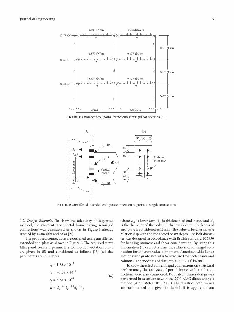