Embed Size (px)
Citation preview
1
SEISMIC PERFORMANCE OF A NEW
SEMIACTIVE TUNED LIQUID COLUMN DAMPER
Okyay ALTAY1, Christoph BUTENWEG2, Sven KLINKEL3
Dirk ABEL4, Matthias REITER5 and Felix NOLTEERNSTING6
ABSTRACT
Passive tuned mass damper (TMD) can be tuned only to a one specific natural frequency. As the
frequency of the structure shifts due to degradation effects, the TMD loses its performance. This
frequency change can occur due to damage to structural elements or temperature and soil effects. In
order to solve this problem a semiactive tuned liquid column damper (S-TLCD) is developed, which
can adapt its frequency and damping ratio to the changing structural properties and loading situation.
The seismic performance of the S-TLCD is verified by means of the 20-story benchmark building and
compared with a conventional passive TMD-system. The acquired results show that, the S-TLCD
performs despite the frequency shift a better efficiency than the passive TMD.
INTRODUCTION
Seismic loading threatens both the safety and the serviceability of structures. During the last Haiti
earthquake in the capital city Port au Prince more than 100,000 homes have been destroyed and
220,000 people have lost their life as reported by EERI (2010). High seismic risk is also valid for
many regions in Europe. For instance, the Emilia-Romagna-Earthquake in Italy has caused an
economic loss of more than 11.5 billion Euros as documented by the Italian Senate (Senato Della
Repubblica, 2012). In order to mitigate seismic vibrations numerous strategies have been developed,
which can be classified as passive, active and semiactive systems.
Examples for passive dissipation systems are hysteretic metallic dampers. Active systems use
actuators to induce supplemental forces on the host structure. Passive and active methods can also be
combined and used together. The so-called hybrid systems can function as a passive device in case of
a failure of the active system. Both active and hybrid devices can reduce structural vibrations
effectively. Nevertheless, the energy demand level of the actuators affects the application of these
methods. Compared with other strategies the implementation of passive dissipation devices is more
1 Dr.-Ing., RWTH Aachen University, Chair of Structural Analysis and Dynamics, Aachen, Germany,
[email protected] 2 Dr.-Ing., RWTH Aachen University, Chair of Structural Analysis and Dynamics, Aachen, Germany,
[email protected] 3 Prof. Dr.-Ing., RWTH Aachen University, Chair of Structural Analysis and Dynamics, Aachen, Germany,
[email protected] 4 Prof. Dr.-Ing., RWTH Aachen University, Institute of Control Engineering, Aachen, Germany,
[email protected] 5 Dipl.-Ing., RWTH Aachen University, Institute of Control Engineering, Aachen, Germany,
[email protected] 6 Dipl.-Ing., RWTH Aachen University, Institute of Control Engineering, Aachen, Germany,
2
straightforward. However, the calibration and maintenance costs are great obstacles for these devices.
In order to solve this problem, semiactive damping systems are developed, which can sense the actual
condition of the structure and adapt their dynamic properties in real time. These adaptive devices offer
a broad range of new application possibilities also for the seismic protection of structures.
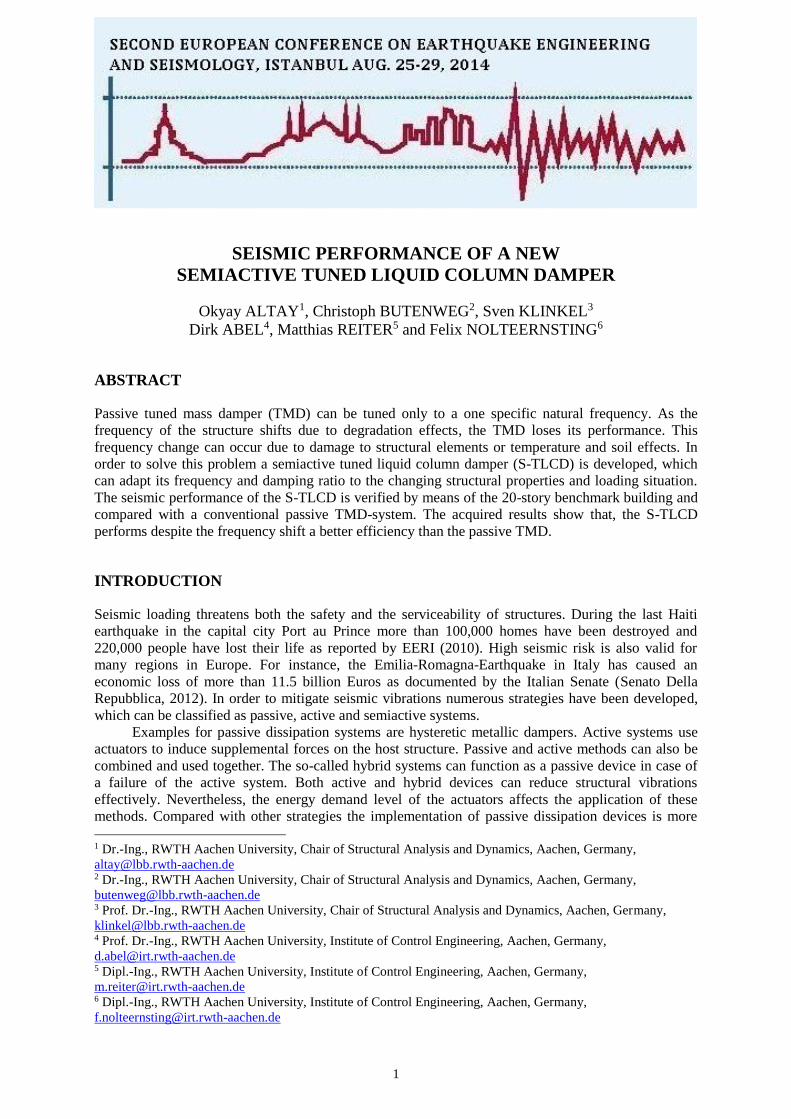
Fig.1 shows the passive, active and semiactive damping methods by means of a tuned mass
damper (TMD), which is connected to a primary structure by a dashpot. The mass m of the passive
TMD oscillates with a phase shift against the motion of the mass M of the primary structure, leading to
restoring forces. Hereby the motion of the structure activates the damper mass. The mass of an active
TMD starts its oscillation by an actuator A with a controller C, which detects the structure and the
damper by sensors S. The semiactive TMD can modify its dynamic properties according to the real-
time data acquired by the sensors S, which are then evaluated by the controller C.
A
S
S
C
S
A
C
M
m
S
B C
M
m
M
m
Figure 1. Passive (A), active (B) and semiactive (C) tuned mass damper attached to a primary structure
TUNED LIQUID COLUMN DAMPER
The tuned liquid column damper (TLCD) consist of a U-shaped tube filled with a Newtonian liquid
such as water. As patented by Frahm (1910) the tuned parameters enable the liquid mass of a passive
TLCD to oscillate against the structure. Its geometric versatility and the low prime costs make the
TLCD an attractive alternative to other damping systems. As the TLCD does not need any auxiliary
springs or other mechanical components, they require a low maintenance compared with the
conventional TMD.
The TLCD counts as one of the first damping devices and was originally invented to mitigate
rolling motions of ships. In civil engineering, the TLCD has become known first after the patent
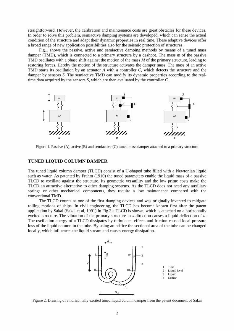
application by Sakai (Sakai et al, 1991) In Fig.2 a TLCD is shown, which is attached on a horizontally
excited structure. The vibration of the primary structure in x-direction causes a liquid deflection of u.
The oscillation energy of a TLCD dissipates by turbulence effects and friction caused local pressure
loss of the liquid column in the tube. By using an orifice the sectional area of the tube can be changed
locally, which influences the liquid stream and causes energy dissipation.
1
3
2
4
1 Tube
2 Liquid level
3 Liquid
4 Orifice
I IV
II III
x
u
V
Heff
Figure 2. Drawing of a horizontally excited tuned liquid column damper from the patent document of Sakai

O.Altay, C.Butenweg, S.Klinkel, D.Abel, M.Reiter and F.Nolteernsting 3
As given in Eq.(1) the natural frequency fD of a TLCD with two vertical liquid columns, which
are connected by a horizontal tube of any arbitrary form, depends only on the total length L of the
liquid column from liquid level I to IV. Hereby the cross-section of the tube is constant.
L
gf
D
D
2
2
1
2
(1)
The nonlinear equation of motion of a TLCD (Eq.2) can be derived using Bernoulli’s principle,
which describes the correlation between the speed and pressure of a fluid flow along a streamline. As
shown in Fig.2 u is the liquid deflection of TLCD, x the horizontal acceleration and xg the seismic base
excitation of the structure. In Eq.(2) the turbulence and friction effects caused pressure loss is
specified by δP. The so-called geometric factor γ, which scales the interaction force between structure
and TLCD, depends as given in Eq.(3) on the ratio of the horizontally projected length Heff of the
horizontal stream line to the total liquid column length L.
gDP xxuuuu 2 (2)
L
H eff (3)
The equation of a single degree of freedom (SDOF) oscillator with a TLCD is given in Eq.(4).
The damping ratio and the natural circular frequency of the structure are defined as DM and ωM. The
SDOF-oscillator is excited by a dynamic force f(t) such as wind and a base excitation xg. The mass
ratio between TLCD and the mass of the oscillation is given by µ.
force Damping
2 )(2 uxxµxtfxxDx ggMMM (4)
The damping force of TLCD can be acquired from the impulse of the liquid, which is given in
Eq.(5) and calculated from the absolute velocity x + u and the mass of the liquid column. Hereby ρ is
the liquid density, A the tube cross-section and dL the length of an infinitesimal fluid element in liquid
column.
IV
I
AdLuxI (5)
The restore force caused by the deflection u of the liquid column is scaled by the geometric
factor γ. The Eq.(6) gives the so-called active mass ratio µ* of a TLCD, which is also relevant for the
efficiency of the damper.
11 µ
µµ (6)
The velocity of a liquid column depends on the cross-section of the streamline. Therefore, most of the
dynamic properties of TLCD can be modified by changing the cross-section of the tube. A general
definition for the natural frequency of TLCD is given in Eq.(7). Hereby compared to Eq.(1) the total
length L of the tube is replaced by the effective length L1. Furthermore, a sinus term is used in order to
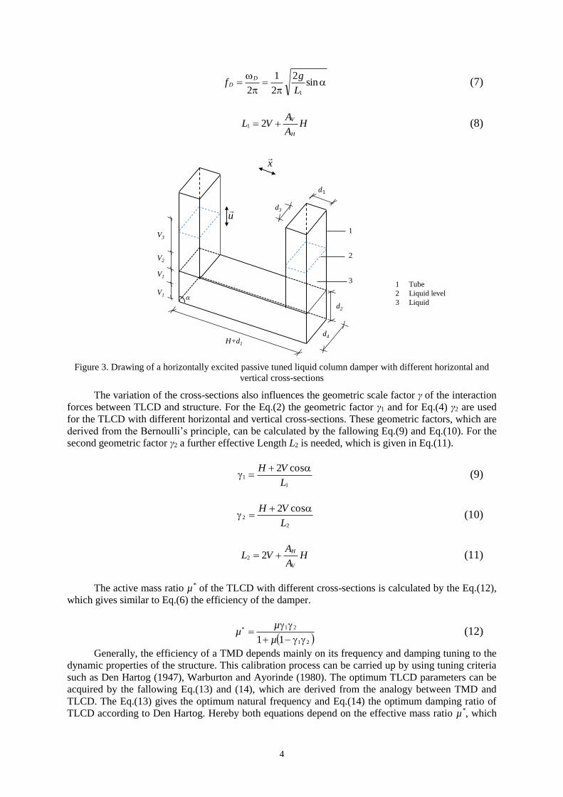
include the influence of the vertical liquid columns inclined by α. As given in Eq.(8) the effective
length equals to the length of the vertical columns V and the horizontal tube length H scaled by the
ratio of the cross-sections of the vertical AV and horizontal AH areas as shown in Fig.3.
4
sin
2
2
1
2 1L
gf
D
D (7)
HA
AVL
H
V 21 (8)
1 Tube
2 Liquid level
3 Liquid
V3
V2
V1
V1
H+d1
d4
d2
d3
2
1
3
x
u
α
Figure 3. Drawing of a horizontally excited passive tuned liquid column damper with different horizontal and
vertical cross-sections
The variation of the cross-sections also influences the geometric scale factor γ of the interaction
forces between TLCD and structure. For the Eq.(2) the geometric factor γ1 and for Eq.(4) γ2 are used
for the TLCD with different horizontal and vertical cross-sections. These geometric factors, which are
derived from the Bernoulli’s principle, can be calculated by the fallowing Eq.(9) and Eq.(10). For the
second geometric factor γ2 a further effective Length L2 is needed, which is given in Eq.(11).
1
1
cos2
L
VH (9)
2
2
cos2
L
VH (10)
HA
AVL
V
H 22 (11)
The active mass ratio µ* of the TLCD with different cross-sections is calculated by the Eq.(12),
which gives similar to Eq.(6) the efficiency of the damper.
21
21
11
µ
µµ (12)
Generally, the efficiency of a TMD depends mainly on its frequency and damping tuning to the
dynamic properties of the structure. This calibration process can be carried up by using tuning criteria
such as Den Hartog (1947), Warburton and Ayorinde (1980). The optimum TLCD parameters can be
acquired by the fallowing Eq.(13) and (14), which are derived from the analogy between TMD and
TLCD. The Eq.(13) gives the optimum natural frequency and Eq.(14) the optimum damping ratio of
TLCD according to Den Hartog. Hereby both equations depend on the effective mass ratio µ*, which
O.Altay, C.Butenweg, S.Klinkel, D.Abel, M.Reiter and F.Nolteernsting 5
has to be calculated by using the Eq.(6) for TLCD with constant cross-section and Eq.(12) for TLCD
with variable cross-section. The Eq.(13) depends also on the natural frequency fM of the main
structure’s mode, which is relevant for the response of the structure. If the vibration of the structure is
influenced by more than one mode a damper system consisting of several TLCD can be used, which
are tuned to the natural frequencies of the modes.
µ
ff
M
optD
1, (13)
3
,
18
3
µ
µD optD (14)
As the efficiency of a TLCD also depends on its geometric factors more comprehensive
optimization methods are also developed, which can calculate not only the optimum frequency and
damping ratio but also the optimum TLCD geometry with a maximum active damper mass ratio
(Altay et al., 2014a and 2014b).
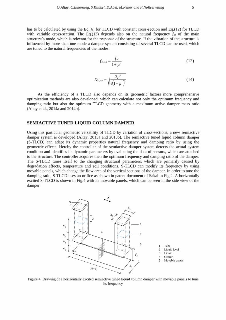
SEMIACTIVE TUNED LIQUID COLUMN DAMPER
Using this particular geometric versatility of TLCD by variation of cross-sections, a new semiactive
damper system is developed (Altay, 2013a and 2013b). The semiactive tuned liquid column damper
(S-TLCD) can adapt its dynamic properties natural frequency and damping ratio by using the
geometric effects. Hereby the controller of the semiactive damper system detects the actual system
condition and identifies its dynamic parameters by evaluating the data of sensors, which are attached
to the structure. The controller acquires then the optimum frequency and damping ratio of the damper.
The S-TLCD tunes itself to the changing structural parameters, which are primarily caused by
degradation effects, temperature and soil conditions. S-TLCD can modify its frequency by using
movable panels, which change the flow area of the vertical sections of the damper. In order to tune the
damping ratio, S-TLCD uses an orifice as shown in patent document of Sakai in Fig.2. A horizontally
excited S-TLCD is shown in Fig.4 with its movable panels, which can be seen in the side view of the
damper.
1 Tube
2 Liquid level
3 Liquid
4 Orifice
5 Movable panels
V3
V2
V1
V1
H+d1
d4
d2
d3
2
1
3
4
5
x
u
α
Figure 4. Drawing of a horizontally excited semiactive tuned liquid column damper with movable panels to tune
its frequency
6
The dynamic properties of S-TLCD are derived similar to the passive TLCD by using
Bernoulli’s principle. From the above-introduced equations, only the effective lengths L1 and L2 are
calculated differently (Eq.15 and Eq.16). The natural frequency is calculated again by the Eq.(7). The
equations of motions are analogous to Eq.(2) and Eq.(4). Hereby the geometric factors need to be
calculated by the Eq. (9) an Eq. (10).
HA
AVV
A
AVVL
H
V
V
V 1
21
2
1
231 22 (15)
HA
AVV
A
AVVL
V
H
V
V
1
21
1
2
232 22 (16)
By adaptive tuning properties of the frequency and damping ratio the S-TLCD provides
permanently, a higher damper efficiency compared to the other passive damper systems. The optimum
S-TLCD parameters can be calculated by using comprehensive optimization methods as introduced by
Altay et al. (2014a) and (2014b). This enables a better seismic performance, which is going to be
numerically verified in next section.
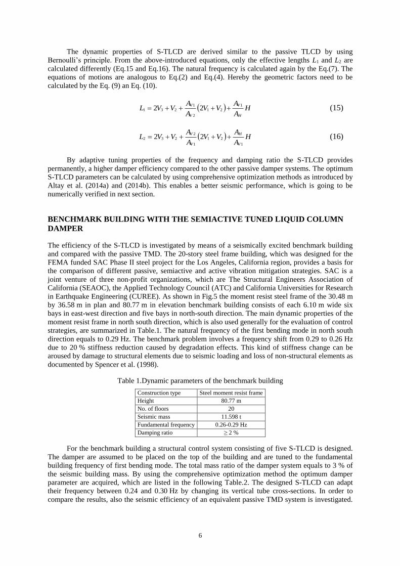
BENCHMARK BUILDING WITH THE SEMIACTIVE TUNED LIQUID COLUMN
DAMPER
The efficiency of the S-TLCD is investigated by means of a seismically excited benchmark building
and compared with the passive TMD. The 20-story steel frame building, which was designed for the
FEMA funded SAC Phase II steel project for the Los Angeles, California region, provides a basis for
the comparison of different passive, semiactive and active vibration mitigation strategies. SAC is a
joint venture of three non-profit organizations, which are The Structural Engineers Association of
California (SEAOC), the Applied Technology Council (ATC) and California Universities for Research
in Earthquake Engineering (CUREE). As shown in Fig.5 the moment resist steel frame of the 30.48 m
by 36.58 m in plan and 80.77 m in elevation benchmark building consists of each 6.10 m wide six
bays in east-west direction and five bays in north-south direction. The main dynamic properties of the
moment resist frame in north south direction, which is also used generally for the evaluation of control
strategies, are summarized in Table.1. The natural frequency of the first bending mode in north south
direction equals to 0.29 Hz. The benchmark problem involves a frequency shift from 0.29 to 0.26 Hz
due to 20 % stiffness reduction caused by degradation effects. This kind of stiffness change can be
aroused by damage to structural elements due to seismic loading and loss of non-structural elements as
documented by Spencer et al. (1998).
Table 1.Dynamic parameters of the benchmark building
Construction type Steel moment resist frame
Height 80.77 m
No. of floors 20
Seismic mass 11.598 t
Fundamental frequency 0.26-0.29 Hz
Damping ratio ≥ 2 %
For the benchmark building a structural control system consisting of five S-TLCD is designed.
The damper are assumed to be placed on the top of the building and are tuned to the fundamental
building frequency of first bending mode. The total mass ratio of the damper system equals to 3 % of
the seismic building mass. By using the comprehensive optimization method the optimum damper
parameter are acquired, which are listed in the following Table.2. The designed S-TLCD can adapt
their frequency between 0.24 and 0.30 Hz by changing its vertical tube cross-sections. In order to
compare the results, also the seismic efficiency of an equivalent passive TMD system is investigated.
O.Altay, C.Butenweg, S.Klinkel, D.Abel, M.Reiter and F.Nolteernsting 7
The natural frequency of TMD is tuned to the fundamental building frequency of 0.29 Hz by using
Den Hartog’s criteria (Den Hartog, 1947).
A - A
Roof
20.
19.
18.
17.
16.
15.
14.
13.
12.
11.
10.
9.
8.
7.
6.
5.
4.
3.
2.
1.
B-2.
B-1.
A-A
3.9
63
.96
3.9
63
.96
3.9
63
.96
3.9
63
.96
3.9
63
.96
3.9
63
.96
3.9
63
.96
3.9
63
.96
3.9
63
.96
3.9
65
.49
3.6
53
.65 7.3
08
0.7
3 m
6.1
0
36
.58
m
6.10
30.48 m
N
A A
Building Plan
Elevation
Figure 5. The 20-story steel frame benchmark building (Spencer et al., 1998)
Table 2.Parameter of the semiactive tuned liquid column damper
Total mass ratio µ 3 %
Natural damper frequency fD 0.24-0.30 Hz
Damping ratio DD 6.7 %
Horizontal liquid column length H 10 m
Vertical liquid column length ΣVi 2.1 m
Horizontal tube cross-section AH 2.8 m²
Vertical tube cross-section AV1 1.3 m²
AV2 0.8-1.3 m²
Geometric factors γ1∙γ2 0.44
Total damper mass mD 32.4 t
8
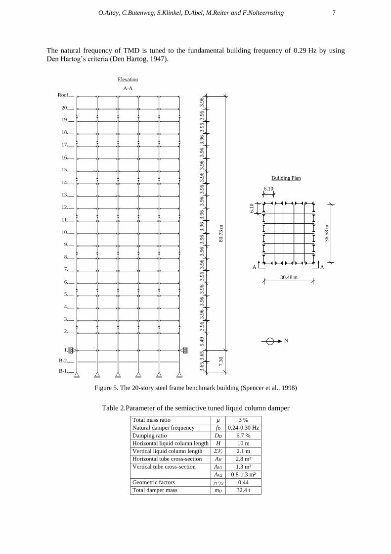
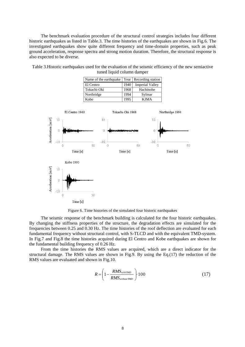
The benchmark evaluation procedure of the structural control strategies includes four different
historic earthquakes as listed in Table.3. The time histories of the earthquakes are shown in Fig.6. The
investigated earthquakes show quite different frequency and time-domain properties, such as peak
ground acceleration, response spectra and strong motion duration. Therefore, the structural response is
also expected to be diverse.
Table 3.Historic earthquakes used for the evaluation of the seismic efficiency of the new semiactive
tuned liquid column damper
Name of the earthquake Year Recording station
El Centro 1940 Imperial Valley
Tokachi-Oki 1968 Hachinohe
Northridge 1994 Sylmar
Kobe 1995 KJMA
Figure 6. Time histories of the simulated four historic earthquakes
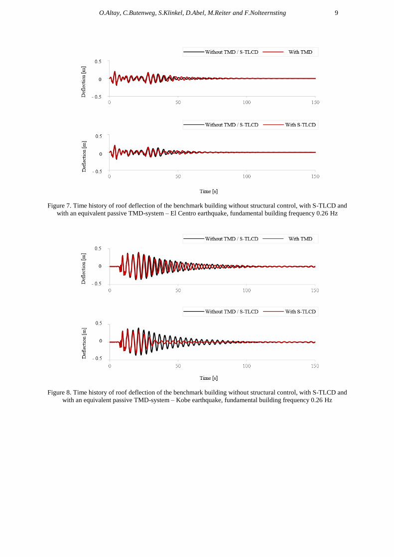
The seismic response of the benchmark building is calculated for the four historic earthquakes.
By changing the stiffness properties of the structure, the degradation effects are simulated for the
frequencies between 0.25 and 0.30 Hz. The time histories of the roof deflection are evaluated for each
fundamental frequency without structural control, with S-TLCD and with the equivalent TMD-system.
In Fig.7 and Fig.8 the time histories acquired during El Centro and Kobe earthquakes are shown for
the fundamental building frequency of 0.26 Hz.
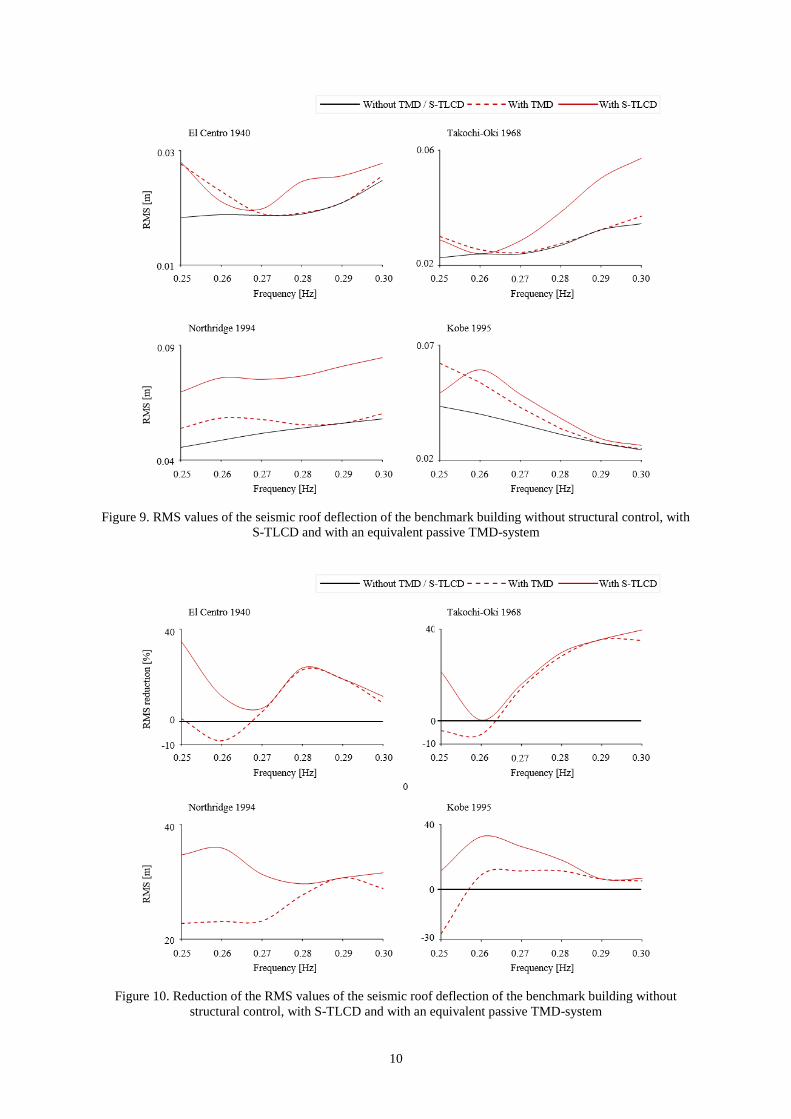
From the time histories the RMS values are acquired, which are a direct indicator for the
structural damage. The RMS values are shown in Fig.9. By using the Eq.(17) the reduction of the
RMS values are evaluated and shown in Fig.10.
1001
TMDwithout
TMDwith
RMS
RMSR (17)
O.Altay, C.Butenweg, S.Klinkel, D.Abel, M.Reiter and F.Nolteernsting 9
Figure 7. Time history of roof deflection of the benchmark building without structural control, with S-TLCD and
with an equivalent passive TMD-system – El Centro earthquake, fundamental building frequency 0.26 Hz
Figure 8. Time history of roof deflection of the benchmark building without structural control, with S-TLCD and
with an equivalent passive TMD-system – Kobe earthquake, fundamental building frequency 0.26 Hz
10
Figure 9. RMS values of the seismic roof deflection of the benchmark building without structural control, with
S-TLCD and with an equivalent passive TMD-system
Figure 10. Reduction of the RMS values of the seismic roof deflection of the benchmark building without
structural control, with S-TLCD and with an equivalent passive TMD-system
O.Altay, C.Butenweg, S.Klinkel, D.Abel, M.Reiter and F.Nolteernsting 11
The acquired results show that, the vibration mitigation of the passive TMD-system varies
depending on the frequency and time domain properties of the seismic excitation. From the four
investigated earthquakes, the maximum reduction is reached during the Tokachi-Oki earthquake with
about 35.6 % at the fundamental frequency of the building. On the other hand, during Kobe
earthquake despite the optimum frequency tuning the dissipated energy amount equals to only 6.8 %,
which shows the correlation between the TMD performance and the earthquake properties. This effect
can also be clearly seen during the El Centro earthquake. Hereby the TMD shows its maximum
performance not at the fundamental building frequency but rather at 0.28 Hz with 23.2 %.
The seismic efficiency of a passive TMD depends beside the earthquake properties also on the
frequency tuning. As the frequency of the structure shifts due to degradation effects, the passive
damper system loses its efficiency. As S-TLCD can adapt its dynamic properties to the real structural
and loading conditions, the frequency tuning remains always optimal. The difference between the
passive TMD and the S-TLCD is obvious especially at the lower limit frequency of 0.25 Hz. During
Tokachi-Oki and Kobe earthquakes, the passive TMD-system even amplifies the vibration of the
structure with -4.2 and -26.4 % due to the frequency detuning. The vibration reduction by the S-TLCD
is at this frequency 21.5 % during Takochi-Oki and 11.8 % during Kobe earthquake. The S-TLCD
shows over the whole frequency spectra a better energy dissipation efficiency than the passive TMD.
The S-TLCD-system reaches its maximum performance during the Takochi-Oki earthquake at the
0.30 Hz with 39.7 %.
CONCLUSIONS
The numerical verification calculations show that, the frequency shift of the benchmark building
caused by degradation effects reduces the energy dissipation efficiency of the passive TMD-system,
which can only be tuned to a one specific frequency. The passive TMD can even amplify the structural
vibration due to frequency detuning. The frequency adaptation character of the S-TLCD enables a
broader range of application properties, as the tuning of the S-TLCD remains always optimum. As a
result the S-TLCD shows a significantly better seismic performance than the passive TMD.
FUTURE WORK
The comparison of the time histories show that, S-TLCD can mitigate effectively especially the
periodic vibrations with resonant character, which occur shortly after the earthquake. The reaction
time of the damper mass for the impacts, which excite the structures during the earthquake, is not
sufficient. In order to reduce this kind of transient vibrations active dampers are developed. However,
as mentioned above the permanent energy demand makes the application of this structural control
strategy difficult. Transient vibrations can be mitigated by improving the general damping properties
of the structure. Therefore, future work is concerned with the low-cost and robust auxiliary dampers,
which can be easily integrated to the structures. Hereby the investigation of new kind of materials like
shape memory alloys, which can replace the conventional metallic dampers due to their unique
hysteric behavior and shape recovery property, is going to be the main aim of the future work.
Future work also includes the experimental research to optimize the performance of the S-
TLCD. Hereby shaking table tests are being carried out, to investigate the operational process of the S-
TLCD including its sensors and controller.
ACKNOWLEDGMENTS
This research work is funded by the Excellence Initiative of the German federal and state
governments.
12
REFERENCES
EERI (2010) “The MW 7.0 Haiti Earthquake of January 12, 2010”, EERI Special Earthquake Report, May
Senato Della Repubblica (2012) “Risoluzione Della 9a Commissione Permanente”, doc. XXIV, n. 43
Frahm H (1910) “Means for Damping the Rolling Motion of Ships”, US-Patent, 970,368
Sakai F, Takaeda S, Tamaki T (1991) “Damping Device for Tower-Like Structure, US-Patent, 5,070,663
Den Hartog JP (1947) Mechanical Vibrations, McGraw-Hill, New York
Warburton GB and Ayorinde O (1980) “Optimum Absorber Parameters for Simple Systems” Earthquake
Engineering and Structural Dynamics, 8(3):197-217
Altay O, Butenweg C, Klinkel S (2014a) Vibration Mitigation of Wind Turbine Towers by Tuned Liquid
Column Dampers, Proceedings of the IX. Int. Conf. on Structural Dynamics, Porto, Portugal, 30 June-2
July
Altay O, Butenweg C, Klinkel S (2014b) Vibration Mitigation of Wind Turbine Towers by a New Semiactive
Tuned Liquid Column Damper, Proceedings of the 6th World Conference on Structural Control and
Monitoring, Barcelona, Spain, 15-17 July
Altay O (2013a) Flüssigkeitsdämpfer zur Reduktion periodischer und stochastischer Schwingungen turmartiger
Bauwerke, Ph.D. Thesis, RWTH Aachen University, Germany
Altay O (2013b) Semiaktives Flüssigkeitssäulendämpfungssystem, German patent application
AZ 10201300595.1, 26 June
Spencer Jr BF, Christenson RE, Dyke SJ (1998) „Next Generation Benchmark Control Problem for Seismically
Excited Buildings”, Proceedings of the 2nd World Conference on Structural Control, Kyoto, Japan, 28
June-1 July