Embed Size (px)
Citation preview
SEISMIC IMAGE AND AVA ANALYSES USING THE REVERSE TIME MIGRATION (RTM) METHOD
WITH DIFFERENT WAVE EQUATION IMPLEMENTATIONS
Ana Paula dos Santos da Silva1, André Bulcão
2, Luiz Landau
1
1LAB2M/COPPE/UFRJ 2CENPES/PETROBRAS
(1)[email protected], (2)[email protected], (1) [email protected]
ABSTRACT
The purpose of this work is to present and analyze the results of numerical simulations related to the application of three different mathematical models in the acoustic seismic wave propagation in which only compressional waves (P-waves) are contemplated. Andpresent the results of an investigation about how these wave equation implementations can influence the amplitudes of a migrated section in the wave field extrapolation by means of Reverse Time Migration (RTM) approach. The Reverse Time Migration (RTM) method was used in order to derive migrated sections so as to perform a comparison of three different equations: Acoustic Wave Equation and Non-Reflective Wave Equation. The modeling was performed by the Finite Difference Method using a simple model and a complex synthetic Salt model from SEG/EAGE (Society of Exploration Geophysics). From this investigation it is possible to evaluate the quality of migrated seismic images, generating high quality images of complex subsurface geological structures.
Keywords: Reverse Time Migration, Acoustic Modeling, AVA
1. INTRODUCTION
The angle dependent reflectivity of a reservoir target is a crucial input for reservoir characterization. A pre-stack depth migration should be able to produce not only an accurate structural image, but also reliable angle-dependent information. The propose of this work is to present the results of an investigation about how different wave equation implementations can influence the amplitudes of a migrated section in the wave field extrapolation by means of Reverse Time Migration (RTM) approach. These amplitudes are employed in order to perform an analysis of their variations with respect to the incidence angle on a specific reflector (AVA - Amplitude versus Angle), resulting in important information for the reflection coefficients characterization of an interface in sub-surface. The results showed that performing the Reverse Time Migration method with different implementations described in this work to generate plots related to
theoretical reflection coefficients and, therefore, these plots can be used in the AVA analysis.
The Reverse Time Migration (RTM) method was used in order to derive migrated sections so as to perform a comparison of three different equations: Acoustic Wave Equation and Non-Reflective Wave Equation. The modeling was performed by the Finite Difference Method using a complex synthetic salt model from SEG/EAGE. From this investigation it is possible to evaluate the quality of migrated seismic images by using different wave equation implementations thus, generating high quality images of complex subsurface geological structures.
2. METHODOLOGY
The first method used to evaluate the amplitudes and the quality of the images is based on the acoustic wave equation (AC) and is widespread today. This arrangement is taken as a frame of reference.
The next scheme evaluated in this work employs the Non Reflective Wave Equation (NR). The Non Reflective Wave Equation is a modification of the acoustic wave equation where the impedance is constant throughout the model. Reduces the multiple reflections, which are undesirable artifacts in the migration process. Using this equation provides a good result for the migration of "Turning Waves" by reducing the effective coefficient of reflection (becoming zero for the case of normal incidence), as shown by BAYSAL et al. (1984). For homogeneous regions of the velocity model this equation simplifies to the traditional acoustic wave equation.
Finally, simulations are carried out by implementing a scheme of separation of wave field components in its ascending and descending (SC),
developed by BULCÃO et al (2007). In the DirectionaSeparation Scheme, each time step, applies in the fof acoustic waves to carry out a scheme to split the waves field upward and downward directions.
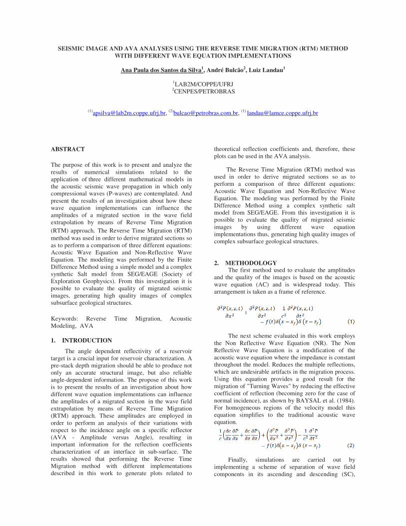
The velocity model adopted to AVA analyses dimensions : x = 5000 m e z = 3000 m. The depth of reflectors are respectively 600 m, 1100m, 1605m and2100m. The compression rates in the model are 2000 m / s, 2100 m/s, 2200 m / s, 2300 m / s and 2500 m / respectively. The grid spacing is 5 m.
Figure1. Velocity model adopted to AVA analyses
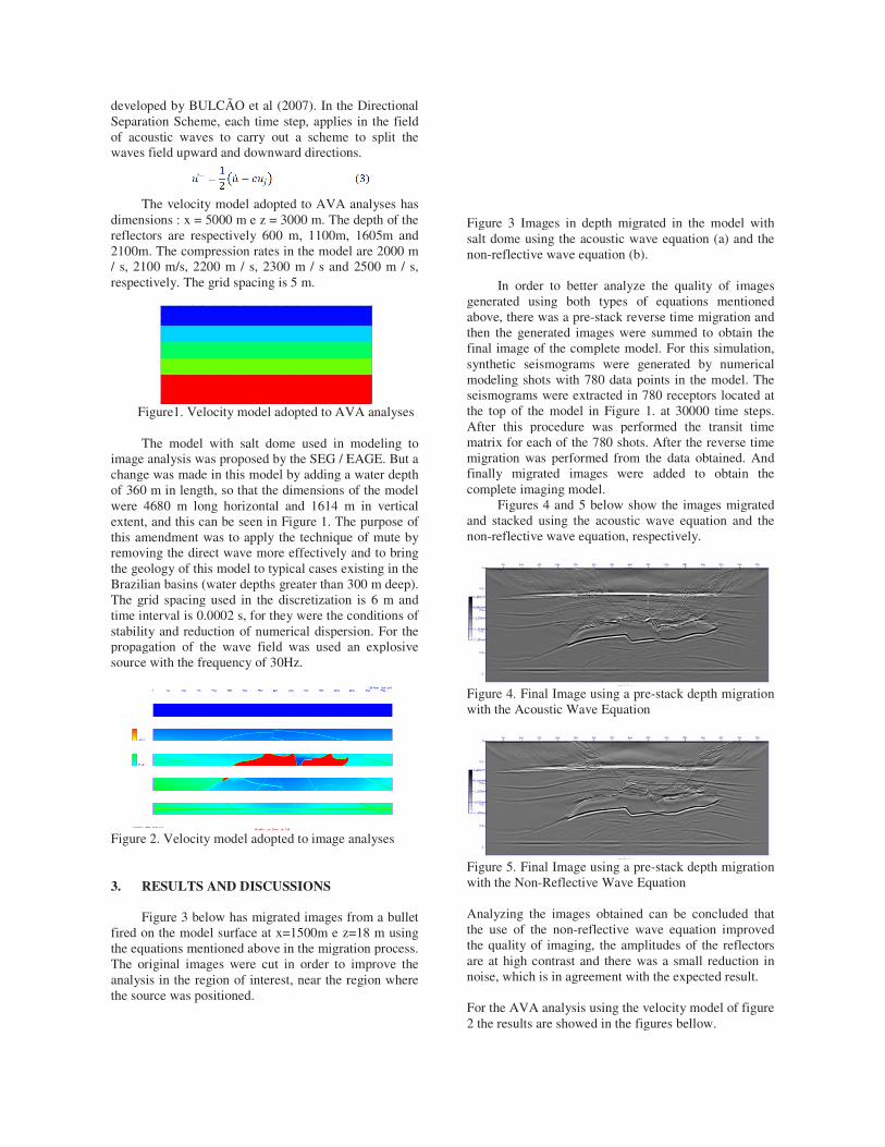
The model with salt dome used in modeling image analysis was proposed by the SEG / EAGEchange was made in this model by adding a water depof 360 m in length, so that the dimensions of the mwere 4680 m long horizontal and 1614 m in vertical extent, and this can be seen in Figure 1. The purpothis amendment was to apply the technique of mute by removing the direct wave more effectively and to brthe geology of this model to typical cases existingBrazilian basins (water depths greater than 300 m dThe grid spacing used in the discretization is 6 m time interval is 0.0002 s, for they were the conditstability and reduction of numerical dispersion. Fopropagation of the wave field was used an explosivesource with the frequency of 30Hz.
Figure 2. Velocity model adopted to image analyse
3. RESULTS AND DISCUSSIONS
Figure 3 below has migrated images from a fired on the model surface at x=1500m e z=18 m usinthe equations mentioned above in the migration procThe original images were cut in order to improve thanalysis in the region of interest, near the region where the source was positioned.
developed by BULCÃO et al (2007). In the Directional Separation Scheme, each time step, applies in the field
ry out a scheme to split the waves field upward and downward directions.
to AVA analyses has dimensions : x = 5000 m e z = 3000 m. The depth of the reflectors are respectively 600 m, 1100m, 1605m and
es in the model are 2000 m / s, 2100 m/s, 2200 m / s, 2300 m / s and 2500 m / s,
Figure1. Velocity model adopted to AVA analyses
The model with salt dome used in modeling to / EAGE. But a
change was made in this model by adding a water depth of 360 m in length, so that the dimensions of the model were 4680 m long horizontal and 1614 m in vertical extent, and this can be seen in Figure 1. The purpose of
pply the technique of mute by removing the direct wave more effectively and to bring the geology of this model to typical cases existing in the Brazilian basins (water depths greater than 300 m deep). The grid spacing used in the discretization is 6 m and time interval is 0.0002 s, for they were the conditions of stability and reduction of numerical dispersion. For the propagation of the wave field was used an explosive
2. Velocity model adopted to image analyses
below has migrated images from a bullet fired on the model surface at x=1500m e z=18 m using the equations mentioned above in the migration process. The original images were cut in order to improve the
he region of interest, near the region where
Figure 3 Images in depth migrated in the model withsalt dome using the acoustic wave equation (a) and non-reflective wave equation (b).
In order to better analyze the qgenerated using both types of equations mentioned above, there was a pre-stack reverse time migration and then the generated images were summed final image of the complete model. synthetic seismograms were generated by numerical modeling shots with 780 data points in the model.seismograms were extracted in 780 receptors located at the top of the model in Figure 1. atAfter this procedure was performed the matrix for each of the 780 shots. After the reverse time migration was performed from the data obtained. Andfinally migrated images were added to obtain the complete imaging model.
Figures 4 and 5 below show the images migrated and stacked using the acoustic wave equatnon-reflective wave equation, respectively.
Figure 4. Final Image using a pre-stack depth migration with the Acoustic Wave Equation
Figure 5. Final Image using a pre-stack depth migration with the Non-Reflective Wave Equation
Analyzing the images obtained can be concluded thatthe use of the non-reflective wave equation improved the quality of imaging, the amplitudes of the refleare at high contrast and there was a small reductionoise, which is in agreement with the
For the AVA analysis using the velocity model of fi2 the results are showed in the figures bellow.
Figure 3 Images in depth migrated in the model with salt dome using the acoustic wave equation (a) and the
reflective wave equation (b).
In order to better analyze the quality of images generated using both types of equations mentioned
stack reverse time migration and summed to obtain the
final image of the complete model. For this simulation, e generated by numerical
modeling shots with 780 data points in the model. The in 780 receptors located at
1. at 30000 time steps. After this procedure was performed the transit time
After the reverse time migration was performed from the data obtained. And finally migrated images were added to obtain the
below show the images migrated and stacked using the acoustic wave equation and the
reflective wave equation, respectively.
stack depth migration
stack depth migration Reflective Wave Equation
Analyzing the images obtained can be concluded that reflective wave equation improved
the quality of imaging, the amplitudes of the reflectors are at high contrast and there was a small reduction in noise, which is in agreement with the expected result.
For the AVA analysis using the velocity model of figure 2 the results are showed in the figures bellow.
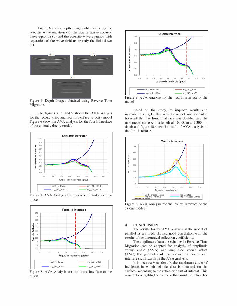
Figure 6 shows depth Images obtained using the acoustic wave equation (a), the non reflexive acoustic wave equation (b) and the acoustic wave equation with separation of the wave field using only the field down (c).
Figure 6. Depth Images obtained using Reverse Time Migration.
The figures 7, 8, and 9 shows the AVA analysis for the second, third and fourth interface velocity model Figure 6 show the AVA analysis for the fourth interface of the extend velocity model.
Figure 7. AVA Analysis for the second interface of the model.
Figure 8. AVA Analysis for the third interface of the model.
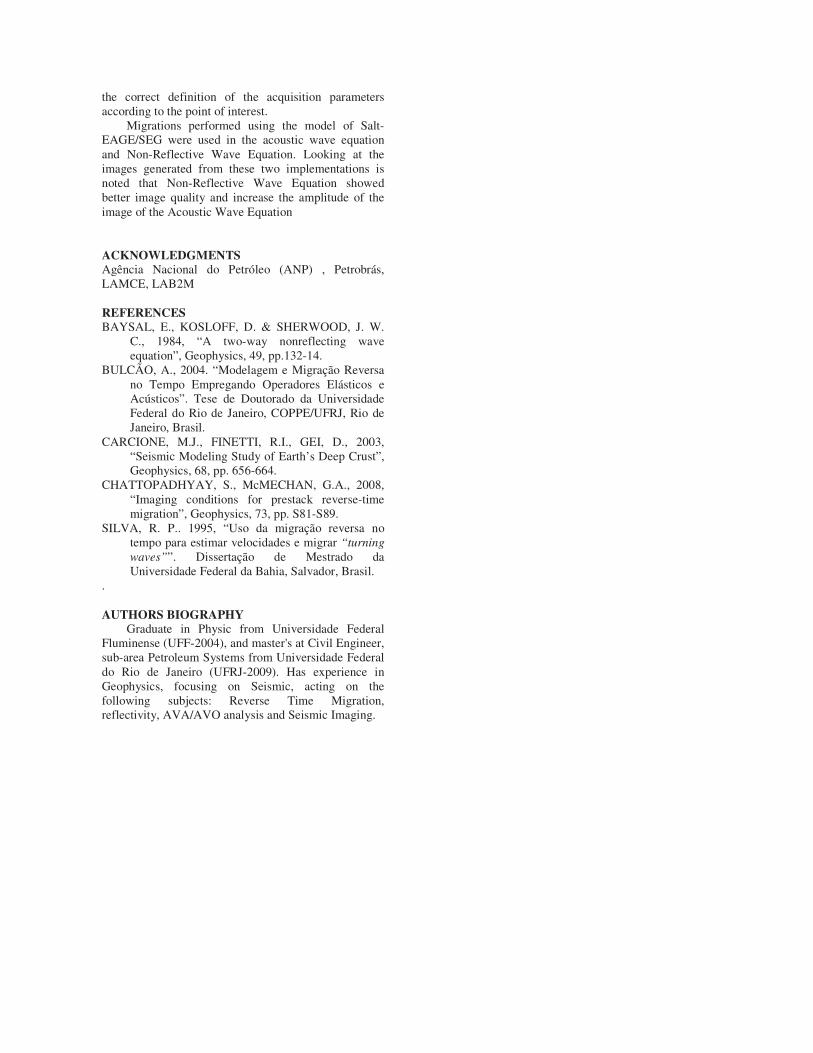
Figure 9. AVA Analysis for the fourth interface of the model
Based on the study, to improve results and increase this angle, the velocity model was extended horizontally. The horizontal size was doubled and the new model came with a length of 10,000 m and 3000 m depth and figure 10 show the result of AVA analysis in the forth interface.
Figure 6. AVA Analysis for the fourth interface of the extend model.
4. CONCLUSION
The results for the AVA analysis in the model of parallel layers used, showed good correlation with the results of the theoretical reflection coefficients.
The amplitudes from the schemes in Reverse Time Migration can be adopted for analysis of amplitude versus angle (AVA) and amplitude versus offset (AVO).The geometry of the acquisition device can interfere significantly in the AVA analysis.
It is necessary to identify the maximum angle of incidence in which seismic data is obtained on the surface, according to the reflector point of interest. This observation highlights the care that must be taken for
0,00
0,01
0,02
0,03
0,04
0,05
0,06
0,07
0,08
0,09
0,10
0,0 10,0 20,0 30,0 40,0 50,0 60,0 70,0
Co
efic
ien
te d
e R
efle
xão
Ângulo de Incidência (graus)
Segunda interface
coef. Reflexao Img_AC_at050
Img_NR_at050 Img_SC_at050
0,00
0,01
0,02
0,03
0,04
0,05
0,06
0,07
0,08
0,09
0,10
0,0 10,0 20,0 30,0 40,0 50,0 60,0 70,0
Co
ef. d
e R
efle
xão
Ângulo de Incidência (graus)
Terceira interface
coef. Reflexao Img_AC_at050
Img_NR_at050 Img_SC_at050
0,01
0,02
0,03
0,04
0,05
0,06
0,07
0,0 5,0 10,0 15,0 20,0 25,0 30,0 35,0 40,0 45,0
Co
efic
ien
te d
e R
efle
xão
Ângulo de Incidência (graus)
Quarta interface
coef. Reflexao Img_AC_at050
Img_NR_at050 Img_SC_at050
0,02
0,04
0,06
0,08
0,10
0,12
0,14
0,0 10,0 20,0 30,0 40,0 50,0 60,0 70,0
Coe
ficin
te d
e R
efle
xão
Ângulo de Incidência (graus)
Quarta interface
Coef. Reflexao Teórico Img_AcusticaImg_Não_Reflexiva Img_Separação_CampoSérie6
the correct definition of the acquisition parameters according to the point of interest.
Migrations performed using the model of Salt-EAGE/SEG were used in the acoustic wave equation and Non-Reflective Wave Equation. Looking at the images generated from these two implementations is noted that Non-Reflective Wave Equation showed better image quality and increase the amplitude of the image of the Acoustic Wave Equation
ACKNOWLEDGMENTS
Agência Nacional do Petróleo (ANP) , Petrobrás, LAMCE, LAB2M
REFERENCES
BAYSAL, E., KOSLOFF, D. & SHERWOOD, J. W. C., 1984, “A two-way nonreflecting wave equation”, Geophysics, 49, pp.132-14.
BULCÃO, A., 2004. “Modelagem e Migração Reversa no Tempo Empregando Operadores Elásticos e Acústicos”. Tese de Doutorado da Universidade Federal do Rio de Janeiro, COPPE/UFRJ, Rio de Janeiro, Brasil.
CARCIONE, M.J., FINETTI, R.I., GEI, D., 2003, “Seismic Modeling Study of Earth’s Deep Crust”, Geophysics, 68, pp. 656-664.
CHATTOPADHYAY, S., McMECHAN, G.A., 2008, “Imaging conditions for prestack reverse-time migration”, Geophysics, 73, pp. S81-S89.
SILVA, R. P.. 1995, “Uso da migração reversa no tempo para estimar velocidades e migrar “turning
waves””. Dissertação de Mestrado da Universidade Federal da Bahia, Salvador, Brasil.
.
AUTHORS BIOGRAPHY
Graduate in Physic from Universidade Federal Fluminense (UFF-2004), and master's at Civil Engineer, sub-area Petroleum Systems from Universidade Federal do Rio de Janeiro (UFRJ-2009). Has experience in Geophysics, focusing on Seismic, acting on the following subjects: Reverse Time Migration, reflectivity, AVA/AVO analysis and Seismic Imaging.


![[Raising AVA - Saving AVA] Auction Catalogue (Full Version)_0807](https://img.pdfslide.us/doc/110x75/568c0f7c1a28ab955a944d6f/raising-ava-saving-ava-auction-catalogue-full-version0807.jpg)