Embed Size (px)
Citation preview
AmericanLifelinesAlliance A public-private partnership to reduce risk to utility and transportation systems from natural hazards and manmade threats
Seismic Guidelines for
Water Pipelines
March 2005
AmericanLifelinesAlliance A public-private partnership to reduce risk to utility and transportation systems from natural hazards and manmade threats
Seismic Guidelines for
Water Pipelines
March 2005
www.americanlifelinesalliance.org
This report was written under contract to the American Lifelines Alliance, a public-private partnership between the Federal Emergency Management Agency (FEMA) and the National Institute of Building Sciences (NIBS). This report was prepared by a team representing practicing engineers in the United States water utility industry and academics.
Acknowledgements The following people and their affiliations contributed to this report.
Person Affiliation
John Eidinger (Chairman) G&E Engineering Systems Inc. Bruce Maison East Bay Municipal Utility District Luke Cheng San Francisco Public Utilities Commission Frank Collins Parsons Mike Conner San Diego Water Department Craig Davis Los Angeles Department of Water & Power Mike Matson Raines, Melton and Carella, Inc. Mike O'Rourke Rennselaer Polytechnic Institute Tom O'Rourke Cornell University Alex Tang Consultant John Wesling Geomatrix Consultants Inc. Mr. Doug Honegger provided technical oversight of this project. Mr. Joseph Steller (NIBS) provided project management for this project.
G&E would also like to thank the numerous staff of the San Francisco Public Utilities Commission, East Bay Municipal Utilities District, City of San Diego Water Department, the Los Angeles Department of Water and Power, and all the other participating agencies for their generous help.
Seismic Guidelines for Water Pipelines
Prepared for: National Institute of Building Sciences
As part of the:
American Lifelines Alliance
Prepared by:
G&E Engineering Systems Inc. 6315 Swainland Rd Oakland, CA 94611
(510) 595-9453 (510) 595-9454 (fax) [email protected]
Principal Investigator:
John Eidinger
G&E Report 80.01.01, Revision 0 March, 2005
Seismic Guidelines for Water Pipelines R80.01.01 Rev. 0
March, 2005 Page i
Table of Contents TABLE OF CONTENTS .................................................................................................................................... I
1.0 INTRODUCTION .........................................................................................................................................1
1.1 OBJECTIVE OF THE GUIDELINES..................................................................................................................1
1.2 PROJECT SCOPE............................................................................................................................................2
1.3 ABBREVIATIONS ..........................................................................................................................................2
1.4 LIMITATIONS................................................................................................................................................6
1.5 UNITS ...........................................................................................................................................................7
1.6 ACROBAT FILE FORMAT..............................................................................................................................7
2.0 PROJECT BACKGROUND........................................................................................................................8
2.1 GOAL OF SEISMIC DESIGN FOR WATER PIPELINES ....................................................................................8
2.2 FLOWCHARTS FOR THE THREE DESIGN METHODS.....................................................................................9
2.3 GUIDELINES CONTEXT ..............................................................................................................................12
3.0 PERFORMANCE OBJECTIVES.............................................................................................................13
3.1 PIPELINE CATEGORIES...............................................................................................................................13
3.2 PIPE FUNCTION CLASS...............................................................................................................................14
3.2.1 Pipe Function Class..........................................................................................................................14
3.2.2 Earthquake Hazard Return Periods ................................................................................................15
3.2.3 Other Function Class Considerations .............................................................................................16
3.3 OTHER GUIDELINES, STANDARDS AND CODES ........................................................................................18
4.0 EARTHQUAKE HAZARDS .....................................................................................................................20
4.1 TRANSIENT GROUND MOVEMENT ............................................................................................................21
4.2 LIQUEFACTION...........................................................................................................................................22
4.3 PERMANENT GROUND MOVEMENT ..........................................................................................................22
4.4 SEISMIC HAZARD ANALYSIS .....................................................................................................................23
4.4.1 Probabilistic Seismic Hazard Analysis (PSHA) .............................................................................24
4.4.2 Alignment Specific Evaluations .......................................................................................................28
4.5 FAULT OFFSET PGD ..................................................................................................................................31
4.6 LIQUEFACTION...........................................................................................................................................34
4.6.1 Liquefaction Induced Permanent Ground Movement ....................................................................36
4.6.2 Buoyancy ...........................................................................................................................................37
4.6.3 Settlement ..........................................................................................................................................37
4.6.4 Spatial Variation of Liquefaction PGDs .........................................................................................38
4.7 LANDSLIDE ASSESSMENT .........................................................................................................................38
5.0 SUBSURFACE INVESTIGATIONS........................................................................................................40
6.0 GENERAL PIPELINE DESIGN APPROACH......................................................................................43
6.1 INTERNAL PRESSURE .................................................................................................................................43
6.2 VERTICAL EARTH LOAD............................................................................................................................43
6.3 SURFACE LIVE LOAD.................................................................................................................................44
6.4 PIPE OVALIZATION ....................................................................................................................................46
6.5 FATIGUE .....................................................................................................................................................48
6.6 FLUID TRANSIENTS....................................................................................................................................48
7.0 ANALYTICAL MODELS..........................................................................................................................50
7.1 THREE MODELS, AND WHEN TO USE THEM.............................................................................................50
7.2 CHART METHOD ........................................................................................................................................50
7.2.1 Transmission Pipelines.....................................................................................................................51
7.2.2 Distribution Pipelines.......................................................................................................................52
Seismic Guidelines for Water Pipelines R80.01.01 Rev. 0
March, 2005 Page ii
7.2.3 Service Laterals and Hydrant Laterals ...........................................................................................53
7.2.4 Design Approach ..............................................................................................................................54
7.3 EQUIVALENT STATIC METHOD .................................................................................................................57
7.3.1 Analysis for Ground Shaking Hazard..............................................................................................57
7.3.2 Landslide and Liquefaction Permanent Ground Deformations.....................................................64
7.3.3 Analysis for Fault Crossing Ground Displacement Hazard .........................................................72
7.4 FINITE ELEMENT METHOD ........................................................................................................................74
7.4.1 Pipe Modeling Guidelines ................................................................................................................76
7.4.2 Soil Modeling Guidelines .................................................................................................................76
7.4.3 Wrinkling Limit .................................................................................................................................85
7.4.4 Tensile Strain Limit...........................................................................................................................87
8.0 TRANSMISSION PIPELINES..................................................................................................................88
8.1 SEISMIC DESIGN ISSUES RELATED TO TRANSMISSION PIPELINES ...........................................................88
8.1.1 Seismic Hazards and Geotechnical Assessment .............................................................................88
8.1.2 Pipe Materials and Wall Thickness .................................................................................................89
8.1.3 Design Earthquakes..........................................................................................................................89
8.1.4 Pipeline Alignment............................................................................................................................90
8.1.5 Soil Mitigation...................................................................................................................................90
8.1.6 Pipe Joints .........................................................................................................................................90
8.1.7 Pipe Structural Design and Analysis ...............................................................................................98
8.1.8 Pipe Supports ....................................................................................................................................99
8.1.9 Pipe Depth and Trench Backfill.....................................................................................................101
8.1.10 Pipe Bend and Thrust Block Design............................................................................................101
8.1.11 Design Features and Appurtenances...........................................................................................101
8.1.12 System Redundancy ......................................................................................................................103
8.1.13 System Modeling ...........................................................................................................................103
8.1.14 Corrosion Control ........................................................................................................................104
8.1.15 Internal Pressure and External Loads ........................................................................................105
8.1.16 Constructability.............................................................................................................................106
8.1.17 Economic Considerations ............................................................................................................106
8.1.18 Environmental Issues....................................................................................................................106
8.1.19 Public Relation or Outreach ........................................................................................................106
8.1.20 Emergency Response Planning....................................................................................................107
8.1.21 Security ..........................................................................................................................................108
8.1.22 Other Special Design Issues.........................................................................................................109
8.2 DESIGN CONSIDERATIONS AT FAULT CROSSINGS..................................................................................109
8.2.1 Fault Types and Fault Zones..........................................................................................................109
8.2.2 Orientation of Pipe with Respect to the Fault Line ......................................................................110
8.2.3 Design Earthquakes and Associated Magnitude of Fault Displacements ..................................110
8.2.4 Geotechnical Hazards ....................................................................................................................111
8.2.5 Soil-Pipeline Interaction ................................................................................................................111
8.2.6 Joints Used to Accommodate Fault Displacements......................................................................111
8.2.7 Analysis Methods ............................................................................................................................113
8.2.8 Design Redundancy ........................................................................................................................114
9.0 SUB-TRANSMISSION PIPELINES ......................................................................................................116
9.1 DESIGN USING THE CHART METHOD......................................................................................................116
9.2 FAULT, LANDSLIDE AND LIQUEFACTION ZONE CROSSINGS .................................................................117
Hazard Bypass System .............................................................................................................................117
9.2.1 Location of isolation valves for bypass relative to mapped hazard ............................................120
9.2.2 Bypass System Components ...........................................................................................................121
9.2.3 Coating System Details...................................................................................................................121
9.2.4 Purchase Specifications for Bypass System Components ............................................................122
9.2.5 Isolation Valve Approach Near Hazards ......................................................................................122
9.2.6 Automation of Isolation Valves ......................................................................................................122
Seismic Guidelines for Water Pipelines R80.01.01 Rev. 0
March, 2005 Page iii
9.3 AVOIDANCE/RELOCATION OF SUB-TRANSMISSION PIPELINE OUT OF HAZARD AREA ........................123
9.3.1 Fault Crossings ...............................................................................................................................123
9.3.2 Landslides........................................................................................................................................123
9.3.3 Areas of Potential Liquefaction .....................................................................................................124
9.4 LIQUEFACTION INDUCED SETTLEMENT ..................................................................................................124
9.4.1 Accommodating Settlements Using Semi-Restrained and Unrestrained Pipe............................124
9.4.2 Accommodating Settlements using Butt Welded Steel Pipe and Butt Fused HDPE Pipe..........124
9.5 SPECIALIZED FITTINGS AND CONNECTIONS ...........................................................................................125
10.0 DISTRIBUTION PIPELINES ...............................................................................................................132
10.1 CAST IRON PIPE .....................................................................................................................................133
10.2 DUCTILE IRON PIPE ...............................................................................................................................133
10.3 PVC PIPE ...............................................................................................................................................137
10.4 HIGH DENSITY POLYETHYLENE PIPE....................................................................................................138
10.5 PERFORMANCE OF COMMON PIPE JOINTS UNDER AXIAL LOADS .......................................................138
10.6 SEISMIC DESIGN RECOMMENDATIONS FOR DISTRIBUTION PIPELINES ...............................................139
10.7 STANDARD INSTALLATION BASED ON AWWA GUIDELINES..............................................................140
11.0 SERVICE AND HYDRANT LATERALS...........................................................................................145
11.1 TYPICAL CUSTOMER SERVICE AND FIRE HYDRANT LATERAL............................................................145
11.2 SEISMIC HAZARDS AND EFFECTS ON APPURTENANCES ......................................................................146
11.3 DESIGN FOR INERTIAL SEISMIC MOTIONS ...........................................................................................146
11.4 DESIGN FOR WAVE PROPAGATION GROUND STRAINS (PGV)............................................................148
11.5 DESIGN FOR PERMANENT GROUND DISPLACEMENT ...........................................................................148
11.5.1 Customer Services ........................................................................................................................149
11.5.2 Fire Hydrant Laterals...................................................................................................................149
12.0 OTHER COMPONENTS.......................................................................................................................156
12.1 EBAA IRON BALL JOINTS AT FAULT CROSSINGS................................................................................156
12.2 EQUIPMENT CRITERIA ...........................................................................................................................158
13.0 REFERENCES.........................................................................................................................................164
C1.0 COMMENTARY ....................................................................................................................................170
C1.1 OBJECTIVE OF THE GUIDELINES ...........................................................................................................170
C1.2 PROJECT SCOPE.....................................................................................................................................171
C1.4 LIMITATIONS .........................................................................................................................................171
C2.0 PROJECT BACKGROUND.................................................................................................................172
C2.2 HYDRODYNAMIC LOADING ..................................................................................................................172
C2.3 GUIDELINES CONTEXT..........................................................................................................................173
C3.0 PERFORMANCE OBJECTIVES........................................................................................................178
C3.1 CATEGORIES OF PIPELINES ...................................................................................................................178
C3.2 PIPE FUNCTION CLASS..........................................................................................................................179
C3.2.1 Pipe Function Class .....................................................................................................................179
C3.2.2 Earthquake Hazard Return Periods............................................................................................183
C3.2.3 Other Function Class Considerations ........................................................................................185
C3.3 OTHER GUIDELINES, STANDARDS AND CODES ...................................................................................191
C3.3.1 2003 International Building Code ..............................................................................................191
C3.3.2 ASCE 7-02. ...................................................................................................................................193
C3.3.3 1997 NEHRP provisions..............................................................................................................194
C3.3.4 1997 Uniform Building Code (UBC) ..........................................................................................194
C3.3.5 1997 JWWA Guidelines ...............................................................................................................195
C3.3.6 ASCE 1984....................................................................................................................................197
C3.3.7 ASCE-ASME 2001........................................................................................................................197
Seismic Guidelines for Water Pipelines R80.01.01 Rev. 0
March, 2005 Page iv
C3.3.8 PRCI 2004 ....................................................................................................................................197
C4.0 EARTHQUAKE HAZARDS ................................................................................................................198
C4.1 TRANSIENT GROUND MOVEMENT .......................................................................................................198
C4.2 LIQUEFACTION ......................................................................................................................................199
C4.3 PERMANENT GROUND MOVEMENT......................................................................................................200
C4.4 SEISMIC HAZARD ANALYSIS ................................................................................................................201
C4.4.1 Probabilistic Seismic Hazard Analysis (PSHA).........................................................................202
C4.4.1.1.1 Getting PGA and PGV...........................................................................................................204
C4.4.2 Design Level PGA and PGV Values ...........................................................................................205
C4.5 FAULT OFFSET ......................................................................................................................................210
C4.6 LIQUEFACTION ......................................................................................................................................213
C4.6.1 Simplified Method to Prepare a Regional Liquefaction Map ...................................................216
C4.6.2 Buoyancy ......................................................................................................................................220
C4.6.3 Settlement......................................................................................................................................220
C4.6.4 Spatial Variation of Liquefaction PGDs ....................................................................................221
C4.6.5 Application of Regional Liquefaction Map ................................................................................221
C4.7 LANDSLIDE ASSESSMENT .....................................................................................................................221
C4.8 GROUND MOTION PARAMETERS IN OTHER CODES.............................................................................226
C5.0 SUBSURFACE INVESTIGATIONS...................................................................................................228
C6.0 GENERAL PIPELINE DESIGN APPROACH.................................................................................228
C6.6 FLUID TRANSIENTS ...............................................................................................................................229
C7.0 ANALYTICAL MODELS.....................................................................................................................229
C7.1 THREE MODELS, AND WHEN TO USE THEM........................................................................................229
C7.2 CHART METHOD ...................................................................................................................................230
C7.2.1 Design Approach..........................................................................................................................230
C7.2.2 Distribution Pipelines ..................................................................................................................231
C7.2.4 Design Approach..........................................................................................................................231
C7.3 EQUIVALENT STATIC METHOD ............................................................................................................231
C7.3.1 Analysis for Ground Shaking Hazard .........................................................................................232
C7.3.2 Analysis for Landslide and Liquefaction Hazard ......................................................................234
C7.3.3 Fault Crossing Ground Displacement Hazard ..........................................................................240
C7.4.1 Pipe Modeling Guidelines ...........................................................................................................241
C7.4.2 Soil Modeling Guidelines ............................................................................................................242
C7.4.3 Wrinkling ......................................................................................................................................242
C7.4.4 Tensile Strain Limit......................................................................................................................243
C8.0 TRANSMISSION PIPELINES.............................................................................................................244
C8.1.2 Pipe Materials and Thickness .....................................................................................................244
C8.1.3 Design Earthquakes .....................................................................................................................245
C8.1.11 Isolation Valves..........................................................................................................................248
C8.1.14 Corrosion....................................................................................................................................248
C8.1.20 Emergency Response Planning .................................................................................................248
C8.2.3 Design Earthquakes and Associated Magnitude of Fault Displacements................................250
C8.2.6 Joints Used to Accommodate Fault Displacements...................................................................250
C8.2.7 Analysis Methods .........................................................................................................................250
C10.0 DISTRIBUTION PIPELINES ............................................................................................................251
C10.2 DUCTILE IRON PIPE.............................................................................................................................251
C11.0 SERVICE LATERALS........................................................................................................................252
C11.4 DESIGN FOR TRANSIENT SEISMIC GROUND STRAINS (PGV) ...........................................................252
C11.5 DESIGN FOR PERMANENT GROUND DISPLACEMENT ........................................................................252

Seismic Guidelines for Water Pipelines R80.01.01 Rev. 0
March, 2005 Page v
C11.5.2 Fire Hydrant Laterals................................................................................................................252
C12.0 OTHER COMPONENTS....................................................................................................................253
C12.2 EQUIPMENT CRITERIA ........................................................................................................................253
C13.0 REFERENCES......................................................................................................................................254
Seismic Guidelines for Water Pipelines R80.01.01 Rev. 0
March, 2005 Page 1
1.0 Introduction The Federal Emergency Management Agency (FEMA) formed in 1998 the American Lifelines Alliance (ALA) as a public-private partnership. In 2002, FEMA contracted with the National Institute of Building Sciences (NIBS) through its Multihazard Mitigation Council (MMC) to, among other things, assist FEMA in continuing the ALA guideline development efforts.
In 2004, NIBS contracted G&E Engineering Systems Inc. to develop these Guidelines for the seismic design of water pipelines.
1.1 Objective of the Guidelines Seismic design for water pipelines is not explicitly included in current AWWA standards. Compounding this problem, standard pipeline materials and installation techniques available to U.S. water utilities have shown themselves to be prone to high damage rates whenever there is significant permanent ground deformations (measured as PGD) or excessively high levels of ground shaking (measured as PGV).
The objective of these Guidelines is to provide a cost effective approach to seismic design of water pipelines, applicable throughout the United States. This means that there should be varying design requirements for different types of pipelines depending upon their overall importance to the network performance of the water utility and the localized risk of earthquakes.
The Guidelines are intended to be:
• Easy to implement. The Guidelines provide typical and seismic pipeline techniques commonly available to water utilities.
• Easy to understand. The Guidelines include practical examples. The Guidelines and commentary provide insight as to the assumptions embedded in the simplified design-by-chart, as well as guidance for detailed pipeline-specific design.
• Easy to use throughout the 50 United States. The Guidelines include methodologies that cover the entire 50 US states, both from the hazard and pipeline installation point of view.
• Easy to use by Small and Large Utilities. Many small water utilities have staffs of 20 or fewer people with perhaps 1 or 2 engineers. The largest water utilities may have staffs of several thousand people, with over 100 engineers. The Guidelines provide methodologies that can be used in both situations.
• Geared to be Cost Effective. The Guidelines are based on "performance based design" concepts, allowing individual utilities to select the seismic design approach that is cost effective for their particular situation at hand.
Seismic Guidelines for Water Pipelines R80.01.01 Rev. 0
March, 2005 Page 2
1.2 Project Scope The Guidelines provide three design methods for water pipelines. Each method is geared to provide suitable water-system-wide performance and post-earthquake recovery in a rare earthquake. In recognition that individual water utilities can have different priorities, available redundancy in their networks, emergency response capability, etc., the Guidelines allow the designer to modify the design requirements for individual pipelines to match local needs.
The Guidelines are intended to be used by water utility personnel, pipe designers and pipe manufacturers. The Guidelines are intended to be comprehensive. Given the wide possible variation in use, the Guidelines provide different design strategies for different situations. The general approach to implementing the Guidelines is as follows:
• Select the Function Class for each pipeline. I, II, III or IV. Section 3.
• Select the design method. Chart method. ESM method, FEM method. Sections 4, 5, 6, 7.
• Design the pipe. Category A, B, C, D or E. Sections 8, 9, 10, 11.
To quickly use these Guidelines, Section 2 provides flow charts that show each step of the design process, for several example situations.
The commentary provides additional background information. Implicit in the decision to use higher-cost pipelines is the question: "is it worth it?" The commentary provides an overview of the key factors that drive the seismic performance of water systems, covering economic losses due to water outages; fire following earthquake; the replace or repair issue for older pipes; and the economic life cycle of pipelines.
The Guidelines refer to three basic design methods. These are called the Chart Method, the Equivalent Static Method (ESM) and the Finite Element Method (FEM). In most situations, the pipeline designer need use only the Chart Method, and need not be concerned about the more analytical and more complicated ESM and FEM methods. By using the Chart Method, the designer should achieve the bulk of the seismic performance intended for good design.
Whichever method the designer uses, the Guidelines provide design solutions that are intended to be cost effective for the situation at hand.
1.3 Abbreviations ASCE American Society of Civil Engineers
ASME American Society of Mechanical Engineers
ALA American Lifelines Alliance
Seismic Guidelines for Water Pipelines R80.01.01 Rev. 0
March, 2005 Page 3
DLF Dynamic Load Factor
DSHA Deterministic Seismic Hazard Analysis
EBMUD East Bay Municipal Utility District
ESM Equivalent Static Method
FEM Finite Element Method
FEMA Federal Emergency Management Agency
G&E G&E Engineering Systems Inc.
GIS Geographical Information System
IBC International Building Code
JWWA Japan Water Works Association
LADWP Los Angeles Department of Water and Power
M Magnitude (moment magnitude)
MG Million Gallons
MGD Million Gallons per Day
MWD Maximum Winter Demand (MGD)
NEHRP National Earthquake Hazards Reduction Program
NEMA National Electrical Manufacturers Association
NIBS National Institute of Building Sciences
P Probability
PGA Peak Ground Acceleration, g
PGD Permanent Ground Displacement, inches
PGV Peak Ground Velocity (measured in inches/second)
PSHA Probabilistic Seismic Hazard Analysis
RR Equivalent Break Repair Rate per 1,000 feet of pipe
SA1 Spectral Acceleration at 1 second period
SCADA Supervisory Control and Data Acquisition
SFPUC San Francisco Public Utilities Commission
TCLEE Technical Council on Lifeline Earthquake Engineering
UBC Uniform Building Code
WTP Water Treatment Plant
Engineering Abbreviations and Units
A Cross sectional area of the pipeline, in2
AD Average surface fault displacement, m
B' Elastic support coefficient
bpf Blows per foot
Seismic Guidelines for Water Pipelines R80.01.01 Rev. 0
March, 2005 Page 4
c Seismic wave propagation speed in soil, feet/sec
cL Wave velocity, feet/second
C Cover depth of burial to the top of the pipeline, feet
Cf Component flexibility factor
Cg Grade mounting coefficient
Cp In structure amplification factor
d lateral offset distance from soil surface load to centerline of pipe
D Pipe diameter to inner wall thickness unless otherwise mentioned, inches
Dl Deflection lag factor
Dmax Maximum surface fault displacement, m
E Pipe material modulus of elasticity, psi
Fa NEHRP ground coefficient
Fv NEHRP ground coefficient
Fp Component design force, pounds
Fu Tensile (ultimate) stress, ksi
Fy Yield stress, ksi
FS Factor of Safety
g Acceleration of gravity, =32.2 feet / second / second
gpm gallons per minute
H Depth of burial to the spring line of the pipeline, feet
hw Depth of water table to the top of the pipeline, feet
hz Hertz (= cycles per second)
I Pipe wall moment of inertia (in4); importance factor
IA Arias intensity
K Bedding constant; bulk modulus of compressibility of water, psi
Ko Coefficient of lateral soil pressure
kV KiloVolt
kips Thousand pounds (kilo pounds)
km kilometer
ksi kips per square inch
L Length (feet or inches)
lb Pound
La Effective length between fault trace and an anchor point, feet
Lv Length from valve to open water surface, feet
Lp Length of pipe between segment joints, feet
LR Level of redundancy (Table 3-3)
Seismic Guidelines for Water Pipelines R80.01.01 Rev. 0
March, 2005 Page 5
m Meter
M Moment magnitude; benign moment in pipe, lb-feet
MD Maximum surface fault displacement
n number of joints in segmented/chained pipe that accommodate PGD
N, N1,60 Blow count form standard penetration test
Nc Soil downward bearing factor
Nch Soil transverse bearing factor (clay)
Ncv Soil bearing factor
Nqh Soil transverse bearing factor (sand)
Nqv Soil vertical bearing factor (sand)
p Pressure (psi)
pu Ultimate bearing force acting in transverse direction of pipe, pounds per inch of pipe length
pcf Pounds per cubic foot
psf Pounds per square foot
psi Pounds per square inch
P External pressure acting on the pipe; tensile force in pipe, kips
Pp Pressure transmitted to pipe from concentrated load
Ps Concentrated load on soil surface
Pv Vertical pressure acting on pipe
Py Yield force (kips)
qa Pipe allowable buckling pressure
qu Transverse (vertical upwards) soil spring, pounds/inch or kips/inch
qu Transverse (vertical downwards) soil spring, pounds/inch or kips/inch
r, R, ri Pipe radius (to inner steel wall), inches
R Closest distance to fault, km (other definitions of distance to fault are also used, as noted)
ro Pipe radius (to outer steel wall), inches
S Section modulus, in3
sec second
Su Undrained soil shear strength, psf
t Pipe wall thickness (inches)
tc Valve closing time (seconds)
tu Ultimate friction force acting in axial direction of pipe (pounds per inch of pipe length)
T Period (seconds)
Seismic Guidelines for Water Pipelines R80.01.01 Rev. 0
March, 2005 Page 6
V Shear force in pipe, kips
Vs Shear wave velocity, feet/sec (m/sec)
W Unit weight of water, =62.4 lb/ft3; or width of soil mass experiencing PGD, feet
xu Yield displacement of soil in axial (local-x) direction, inch
yu Yield displacement of soil in transverse (local-y) direction, inch
Z Free field design peak ground acceleration, g
zu Yield displacement of soil in vertical (local-z) direction, inch
Greek Symbols
Dimensionless factor in soil spring calculation; thrust angle
Acute angle between the fault line and the pipe centerline
Relative joint displacement, or PGD, inches
joint Displacement of joint in segmented pipe, inch
y Pipe vertical deflection
P Rise in water pressure due to rapid valve closure, psi
v Change in water velocity, feet/sec
allow Allowable strain (percent)
g Ground strain, estimate
pipe Peak longitudinal strain in the pipe
soil Peak strain in the soil
uu Ultimate uniform strain (percent)
d Soil dry unit weight, pcf
Soil effective unit weight, pcf
Seismic wave length in soil, feet
μ Poisson's ratio
bw Pipe through wall bending stress, psi
pipe Pipe stress, longitudinal direction, psi
y Yield stress, ksi
u Tensile (ultimate) stress, ksi
1.4 Limitations These Guidelines have been prepared in accordance with generally recognized engineering principles and practices. The Guidelines do not constitute a standard or code, and are not mandatory.
Seismic Guidelines for Water Pipelines R80.01.01 Rev. 0
March, 2005 Page 7
Each section of the Guidelines was prepared by one or more persons listed in the Acknowledgements. Each section has been reviewed by at least one or more other persons listed in the Acknowledgements. The utilities, companies and university affiliations listed in the Acknowledgements have all been gracious and helpful in supporting the development of the Guidelines; but their listing does not mean that they endorse the Guidelines.
The Guidelines should not be used without first securing competent advice with respect to its suitability for any general or specific application. The authors of the Guidelines, ALA, NIBS or FEMA shall not be responsible in any way for the use of the Guidelines.
1.5 Units This report makes use of both common English and SI units of measure.
Most water pipelines in the United States are sized by diameter using inches as the unit of measure. For example, distribution pipes are commonly 6-inch or 8-inch diameter. As these are nominal diameters, the actual measured diameter might vary, depending on lining and coating systems, pressure rating, pipe manufacturer and material. A conversion of a 6-inch diameter pipe to a 152.4 mm diameter pipe implies an accuracy that does not exist; a conversion of a 6-inch diameter pipe to be called a 150 mm diameter pipe implies that the pipe was purchased in a metric system, which in most cases it was not (at least in the United States). Thus, English units of measure are commonly used. SI units are also commonly used where they do not introduce inaccuracies.
For English units, we commonly use pounds and inches, although we sometimes use kips and feet.
Common Conversions
1 kip = 1,000 pounds
1 foot = 12 inches
1 inch = 25.4 mm
1 m = 1,000 mm
1.6 Acrobat File Format If you are viewing a .pdf version of this report, you must use Acrobat Reader version 7 (free from www.adobe.com). Prior versions of Acrobat may improperly display some fonts.
Seismic Guidelines for Water Pipelines R80.01.01 Rev. 0
March, 2005 Page 8
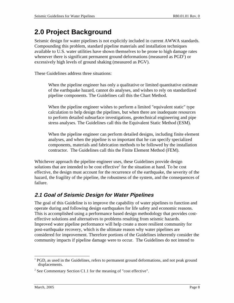
2.0 Project Background Seismic design for water pipelines is not explicitly included in current AWWA standards. Compounding this problem, standard pipeline materials and installation techniques available to U.S. water utilities have shown themselves to be prone to high damage rates whenever there is significant permanent ground deformations (measured as PGD1) or excessively high levels of ground shaking (measured as PGV).
These Guidelines address three situations:
• When the pipeline engineer has only a qualitative or limited quantitative estimate of the earthquake hazard, cannot do analyses, and wishes to rely on standardized pipeline components. The Guidelines call this the Chart Method.
• When the pipeline engineer wishes to perform a limited "equivalent static" type calculation to help design the pipelines, but when there are inadequate resources to perform detailed subsurface investigations, geotechnical engineering and pipe stress analyses. The Guidelines call this the Equivalent Static Method (ESM).
• When the pipeline engineer can perform detailed designs, including finite element analyses, and when the pipeline is so important that he can specify specialized components, materials and fabrication methods to be followed by the installation contractor. The Guidelines call this the Finite Element Method (FEM).
Whichever approach the pipeline engineer uses, these Guidelines provide design solutions that are intended to be cost effective2 for the situation at hand. To be cost effective, the design must account for the recurrence of the earthquake, the severity of the hazard, the fragility of the pipeline, the robustness of the system, and the consequences of failure.
2.1 Goal of Seismic Design for Water Pipelines The goal of this Guideline is to improve the capability of water pipelines to function and operate during and following design earthquakes for life safety and economic reasons. This is accomplished using a performance based design methodology that provides cost-effective solutions and alternatives to problems resulting from seismic hazards. Improved water pipeline performance will help create a more resilient community for post-earthquake recovery, which is the ultimate reason why water pipelines are considered for improvement. Therefore portions of the Guidelines inherently consider the community impacts if pipeline damage were to occur. The Guidelines do not intend to
1 PGD, as used in the Guidelines, refers to permanent ground deformations, and not peak ground
displacements. 2 See Commentary Section C1.1 for the meaning of "cost effective".

Seismic Guidelines for Water Pipelines R80.01.01 Rev. 0
March, 2005 Page 9
prevent all pipelines from being damaged. Rather, it is recognized that earthquakes may cause some limited and manageable pipe damage.
The Guidelines are aimed at helping the pipeline designer to strengthen the pipeline network so that the water system as a whole does not create a life safety problem and contain economic losses to manageable levels.
The Guidelines are applicable for both new installations and replacement of older pipes. The decision to replace old pipes is a complex one. Replacing older 4-inch to 10-inch diameter cast iron pipes solely on the basis of earthquake improvement is not recommended, and this is not commonly cost effective. However, as old pipeline are thought to need replacement because they no longer provide adequate fire flows, or have been observed to require repair at a rate of more than once every 5 years, then the added benefit of improved seismic performance may help justify the pipe replacement. Replacement of larger diameter pipelines (12-inch and upwards) may be cost effective strictly from a seismic point of view, in areas prone to PGDs.
The Guidelines only pertains to the water conveying pipelines. With the exception of equipment commonly used in pipe valve vaults, and anchorage of this equipment (Section 12), the seismic design for appurtenant facilities, such as tanks and pumping stations, etc. are not covered herein, but may directly affect the ability for the pipeline to function and are therefore recommended to be prudently designed consistent with this pipeline design Guidelines.
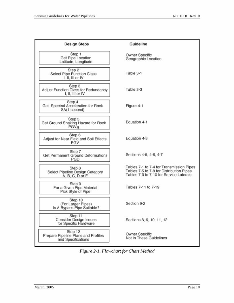
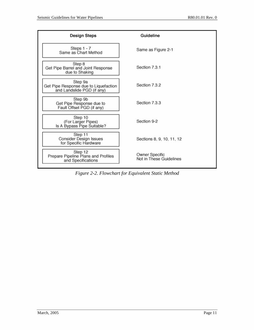
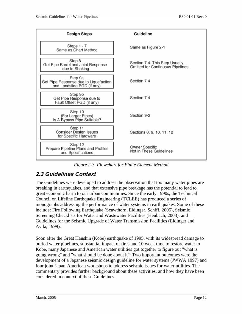
2.2 Flowcharts for the Three Design Methods Figures 2-1, 2-2 and 2-3 provide flowcharts of the general design process using each of the three design methods. In these flowcharts, the key part of the Guidelines is listed that gives the quantified procedures. The user should review the entire Guidelines and Commentary to appreciate the complete design process.
Any step in the flowcharts can be modified to reflect additional information, refined procedures or other considerations that the designer feels appropriate.
The flowcharts do not highlight any design steps needed for non-seismic design. Some of the common non-seismic design issues are outlined in Section 6 and elsewhere in the Guidelines; but the Guidelines are not meant to provide complete or comprehensive non-seismic design guidance.
The flowcharts do not highlight seismic design for hydrodynamic loading. The Guidelines recommend that such loads be considered, especially for segmented pipelines. Comprehensive design tools do not yet exist to quantify hydrodynamic loading. The Guidelines provide suggestions as to how to treat these loads.
Seismic Guidelines for Water Pipelines R80.01.01 Rev. 0
March, 2005 Page 10
Figure 2-1. Flowchart for Chart Method
Seismic Guidelines for Water Pipelines R80.01.01 Rev. 0
March, 2005 Page 11
Figure 2-2. Flowchart for Equivalent Static Method
Seismic Guidelines for Water Pipelines R80.01.01 Rev. 0
March, 2005 Page 12
Figure 2-3. Flowchart for Finite Element Method
2.3 Guidelines Context The Guidelines were developed to address the observation that too many water pipes are breaking in earthquakes, and that extensive pipe breakage has the potential to lead to great economic harm to our urban communities. Since the early 1990s, the Technical Council on Lifeline Earthquake Engineering (TCLEE) has produced a series of monographs addressing the performance of water systems in earthquakes. Some of these include: Fire Following Earthquake (Scawthorn, Eidinger, Schiff, 2005), Seismic Screening Checklists for Water and Wastewater Facilities (Heubach, 2003), and Guidelines for the Seismic Upgrade of Water Transmission Facilities (Eidinger and Avila, 1999).
Soon after the Great Hanshin (Kobe) earthquake of 1995, with its widespread damage to buried water pipelines, substantial impact of fires and 10 week time to restore water to Kobe, many Japanese and American water utilities got together to figure out "what is going wrong" and "what should be done about it". Two important outcomes were the development of a Japanese seismic design guideline for water systems (JWWA 1997) and four joint Japan-American workshops to address seismic issues for water utilities. The commentary provides further background about these activities, and how they have been considered in context of these Guidelines.

Seismic Guidelines for Water Pipelines R80.01.01 Rev. 0
March, 2005 Page 13
3.0 Performance Objectives The seismic design of pipelines and their appurtenances should3 be based on the intended operational performance level the system must achieve in a post-earthquake disaster situation. This requires seismic Performance Objectives to be selected for the system. The Performance Objectives consist of one or more performance goals. Each performance goal consists of two parts:
• Target Performance Level
• Seismic Hazard Level
From the performance goals, each pipeline is identified according to an operational performance reliability. The function of the pipeline within the system defines its importance in achieving the system performance goal and its needed reliability.
3.1 Pipeline Categories Each pipeline should have a target performance level.
The Guidelines provide the following definitions for a "pipeline". These definitions are meant only as a way to provide a common point for communication. For example, one utility's "trunk line" might be another utility's "transmission line" and may be another utility's "aqueduct". If the user wishes to use an alternative definition, then the user may also make corresponding changes in other parts of the Guidelines.
• Transmission pipelines. These are pipelines with nominal diameters from 36-inch to 120-inch (or larger). A transmission pipeline will often deliver water at a rate of 30 MGD to 300 MGD, typically sufficient to serve a population of 100,000 to more than 1,000,000 people. Transmission pipelines are often used for both potable or raw water conveyance.
• Sub-transmission pipelines. These are pipelines with nominal diameters from 16-inch to 30-inch. A sub-transmission pipeline will often deliver water at a rate of 5 MGD to 30 MGD, typically sufficient to serve a population of 10,000 to 100,000 people. Sub-Transmission pipelines are often used for both potable or raw water conveyance.
• Distribution pipelines. These are pipelines with nominal diameters from 6-inch to 12-inch. A distribution pipeline will often deliver water at a rate from under 0.1 MGD to 5 MGD. A 6-inch distribution pipeline could serve a single city street, supporting a population of perhaps a few tens of people. A 12-inch distribution
3 The terms "should", is used in the Guidelines. The Guidelines are not a code or standard, and
everything in the Guidelines is non-mandatory.
Seismic Guidelines for Water Pipelines R80.01.01 Rev. 0
March, 2005 Page 14
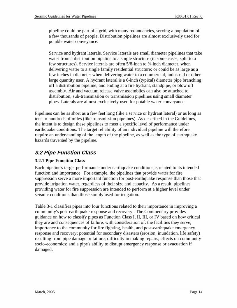
pipeline could be part of a grid, with many redundancies, serving a population of a few thousands of people. Distribution pipelines are almost exclusively used for potable water conveyance.
• Service and hydrant laterals. Service laterals are small diameter pipelines that take water from a distribution pipeline to a single structure (in some cases, split to a few structures). Service laterals are often 5/8-inch to -inch diameter, when delivering water to a single family residential structure; or could be as large as a few inches in diameter when delivering water to a commercial, industrial or other large quantity user. A hydrant lateral is a 6-inch (typical) diameter pipe branching off a distribution pipeline, and ending at a fire hydrant, standpipe, or blow off assembly. Air and vacuum release valve assemblies can also be attached to distribution, sub-transmission or transmission pipelines using small diameter pipes. Laterals are almost exclusively used for potable water conveyance.
Pipelines can be as short as a few feet long (like a service or hydrant lateral) or as long as tens to hundreds of miles (like transmission pipelines). As described in the Guidelines, the intent is to design these pipelines to meet a specific level of performance under earthquake conditions. The target reliability of an individual pipeline will therefore require an understanding of the length of the pipeline, as well as the type of earthquake hazards traversed by the pipeline.
3.2 Pipe Function Class 3.2.1 Pipe Function Class
Each pipeline's target performance under earthquake conditions is related to its intended function and importance. For example, the pipelines that provide water for fire suppression serve a more important function for post-earthquake response than those that provide irrigation water, regardless of their size and capacity. As a result, pipelines providing water for fire suppression are intended to perform at a higher level under seismic conditions than those simply used for irrigation.
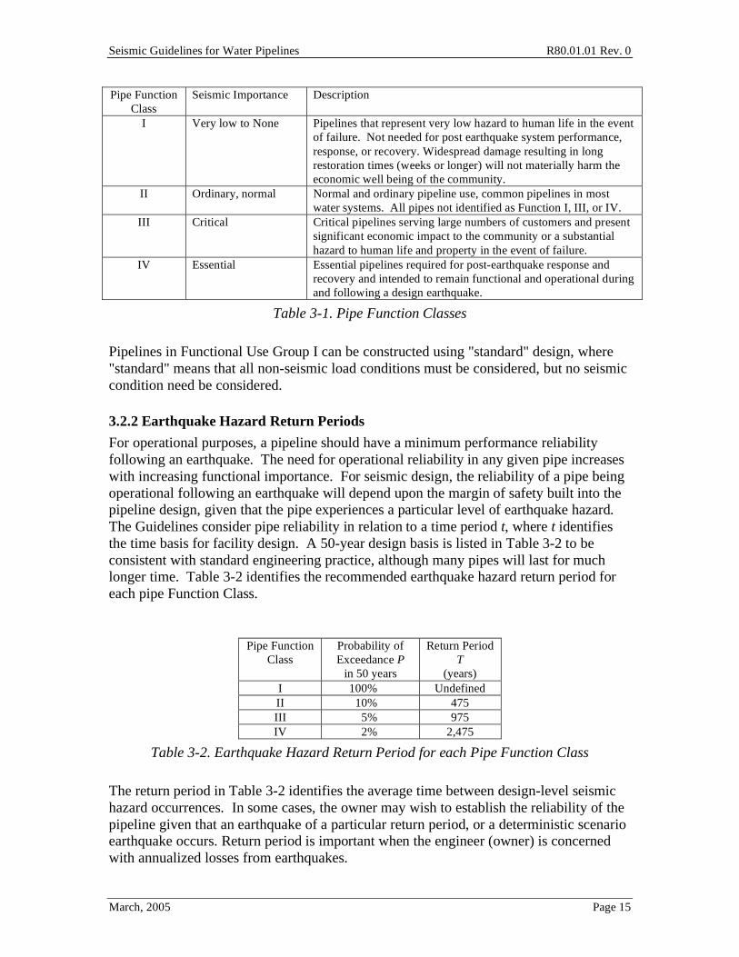
Table 3-1 classifies pipes into four functions related to their importance in improving a community's post-earthquake response and recovery. The Commentary provides guidance on how to classify pipes as Function Class I, II, III, or IV based on how critical they are and consequences of failure, with consideration of: the facilities they serve; importance to the community for fire fighting, health, and post-earthquake emergency response and recovery; potential for secondary disasters (erosion, inundation, life safety) resulting from pipe damage or failure; difficulty in making repairs; effects on community socio-economics; and a pipe's ability to disrupt emergency response or evacuation if damaged.
Seismic Guidelines for Water Pipelines R80.01.01 Rev. 0
March, 2005 Page 15
Pipe Function Class
Seismic Importance Description
I Very low to None Pipelines that represent very low hazard to human life in the event of failure. Not needed for post earthquake system performance, response, or recovery. Widespread damage resulting in long restoration times (weeks or longer) will not materially harm the economic well being of the community.
II Ordinary, normal Normal and ordinary pipeline use, common pipelines in most water systems. All pipes not identified as Function I, III, or IV.
III Critical Critical pipelines serving large numbers of customers and present significant economic impact to the community or a substantial hazard to human life and property in the event of failure.
IV Essential Essential pipelines required for post-earthquake response and recovery and intended to remain functional and operational during and following a design earthquake.
Table 3-1. Pipe Function Classes
Pipelines in Functional Use Group I can be constructed using "standard" design, where "standard" means that all non-seismic load conditions must be considered, but no seismic condition need be considered.
3.2.2 Earthquake Hazard Return Periods
For operational purposes, a pipeline should have a minimum performance reliability following an earthquake. The need for operational reliability in any given pipe increases with increasing functional importance. For seismic design, the reliability of a pipe being operational following an earthquake will depend upon the margin of safety built into the pipeline design, given that the pipe experiences a particular level of earthquake hazard. The Guidelines consider pipe reliability in relation to a time period t, where t identifies the time basis for facility design. A 50-year design basis is listed in Table 3-2 to be consistent with standard engineering practice, although many pipes will last for much longer time. Table 3-2 identifies the recommended earthquake hazard return period for each pipe Function Class.
Pipe Function
Class Probability of Exceedance P
in 50 years
Return Period T
(years) I 100% Undefined II 10% 475 III 5% 975 IV 2% 2,475
Table 3-2. Earthquake Hazard Return Period for each Pipe Function Class
The return period in Table 3-2 identifies the average time between design-level seismic hazard occurrences. In some cases, the owner may wish to establish the reliability of the pipeline given that an earthquake of a particular return period, or a deterministic scenario earthquake occurs. Return period is important when the engineer (owner) is concerned with annualized losses from earthquakes.
Seismic Guidelines for Water Pipelines R80.01.01 Rev. 0
March, 2005 Page 16
3.2.3 Other Function Class Considerations
The pipe function classification and corresponding seismic design level are specific to individual water supply and distribution systems. The following seismic design provisions allow customization of the recommendations in these Guidelines for specific system conditions. These provisions also allow owners to consider cost-effective options in water system seismic improvements through use of redundancies, isolation capabilities, emergency response, etc. as alternatives to hardening specific pipelines.
3.2.3.1 Multiple Use Pipelines
Pipelines providing water service for multiple uses are recommended to be classified under the highest corresponding Function Class in Table 3-1. Where pipe connections and branches come from a higher Function pipeline to serve a lower Function, the branch pipe is recommended to be designed as the higher Function; alternatively, if damage or failure of the branch pipe can be shown not to affect the ability for the higher Function pipe to provide the necessary water service, then the branch pipe may be designed for its intended Function.
3.2.3.2 Continuity
Pipelines and pipeline systems are recommended to be designed for the higher Function for which service is provided from the supply and water treatment source to the point of service. This includes all transmissions pipes, sub-transmission pipes, distribution pipes, and service lateral and hydrant laterals. In many cases the water distributor (sometimes called wholesaler) is only responsible to the point of service connection, usually at a meter connection. Beyond the service connection, the next owner (retail customer) is responsible for the pipe. The water wholesaler and property owner are each responsible for their respective portions of the system to ensure continuity of design, construction, and maintenance to be consistent with designated pipeline Function.
Many water systems receive potable and raw water supplies from wholesale water agencies. For purposes of these Guidelines, systems receiving water from wholesalers are defined as retail agencies. Pipelines providing the wholesale water supplies to the retailer are considered an extension of each retail supply and distribution system and are therefore subject to the same continuity recommendations as all pipes within a retail system. Wholesale pipelines serving urban retailers may generally be classified as Function IV pipes (if non-redundant) unless retailers are shown not to have a need for Function IV supply pipelines. The retailers and wholesalers are each responsible for their respective pipelines and appropriate communication is recommended for both parties to ensure proper continuity for the retailer.
3.2.3.3 Supply Source
For the purposes of these Guidelines, a supply source is defined as a source that provides the minimum normal and/or emergency water supplies to the community it is intended to serve. A source may be one or combination of open or covered reservoirs, tanks,
Seismic Guidelines for Water Pipelines R80.01.01 Rev. 0
March, 2005 Page 17
groundwater supplies, river intakes, aqueduct intakes, etc. that together meet the minimum water supply requirements. If multiple sources are used in combination to meet the minimum supply requirements, each individual supply source should be taken as a source and be classified with the appropriate pipe Function.
3.2.3.4 Redundancy
Redundant pipelines increase the reliability of post-earthquake operations, provided the redundancy meets the following criteria:
1. A leak or break in one pipe will not likely lead to damage on other redundant pipes; and
2. All redundant pipes can provide a minimum needed flow to meet post-earthquake operational needs. The minimum level of flow required after earthquakes should generally be at the maximum winter time flow rate, or a level of water that is sufficient for household and most economic activities of the community; and
3. The redundant pipes are spatially separated by an adequate distance through potential ground deformation zones (landslide, fault movement, ground failure, lateral spreading, etc.) such that, should ground deformation occur, each redundant pipe may not be subjected to the same amount of ground movement due to the natural variation in movement across a deformation zone, regardless of the actual design parameters.
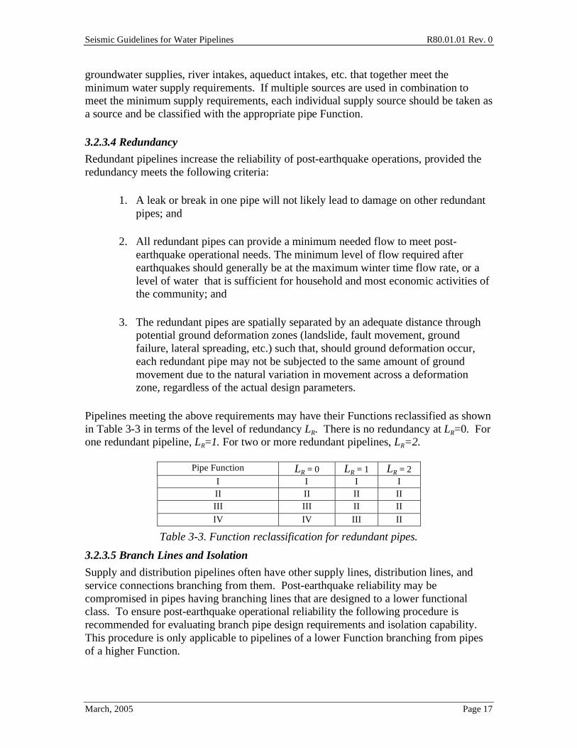
Pipelines meeting the above requirements may have their Functions reclassified as shown in Table 3-3 in terms of the level of redundancy LR. There is no redundancy at LR=0. For one redundant pipeline, LR=1. For two or more redundant pipelines, LR=2.
Pipe Function LR = 0 LR = 1 LR = 2 I I I I II II II II III III II II
IV IV III II
Table 3-3. Function reclassification for redundant pipes.
3.2.3.5 Branch Lines and Isolation
Supply and distribution pipelines often have other supply lines, distribution lines, and service connections branching from them. Post-earthquake reliability may be compromised in pipes having branching lines that are designed to a lower functional class. To ensure post-earthquake operational reliability the following procedure is recommended for evaluating branch pipe design requirements and isolation capability. This procedure is only applicable to pipelines of a lower Function branching from pipes of a higher Function.
Seismic Guidelines for Water Pipelines R80.01.01 Rev. 0
March, 2005 Page 18
1. Determine the Function for the branch pipe using Table 3-1. 2. Determine the Function of the pipe it is branching from. 3. Design the branch pipe for:
a. The lower Function if: i. Isolation valves are installed and the time needed to close these
valves (whether manual or automatic) is acceptable with regards to post-earthquake response and recovery; or
ii. An engineering analysis is performed and shows the branch pipe(s) will not disrupt post-earthquake performance of the higher pipe Function. This evaluation must account for the cumulative effect of potential damage on all branch pipes.
b. The higher function if (a) is not satisfied.
3.2.3.6 Maintenance
One of the greatest seismic mitigations for water pipelines is proper maintenance to ensure pipeline seismic performance. All pipes must be maintained to ensure their proper seismic performance for their Functional Class.
3.2.3.7 Damage and post earthquake repair
These Guidelines are not intended to completely eliminate all seismic induced pipe damage for Function Class II, III and IV pipelines, but it will significantly reduce the damage and post-earthquake recovery time. In addition, the ability for the system to perform during and following an earthquake will be significantly improved. Therefore, it is important for organizations that operate water system pipelines to have adequate capabilities to respond to a design earthquake and make repairs.
3.2.3.8 Earthquake preparedness and response plans
Waterworks organizations are recommended to develop and maintain seismic preparedness and response plans that incorporate methods to respond to and repair pipeline damage following an earthquake. Emergency Operations Centers for non-water works organizations and other non-water critical facilities are encouraged to develop their own emergency preparedness pans that factor in the availability of rapid restoration of water supply post-earthquake.
3.3 Other Guidelines, Standards and Codes Various codes, standards and guidelines already exist that are commonly used for the seismic design of buildings and related facilities, as well as a few that address welded steel pipelines. Many of these were reviewed to assess their possible application for the seismic design of water pipelines. The commentary presents a summary of this review.
Through 2004, there have been de facto no seismic requirements for the design and installation of water pipelines used in the United States. Nationwide codes such as UBC and IBC sometimes touch on the issue, but effectively no one looks to these codes for

Seismic Guidelines for Water Pipelines R80.01.01 Rev. 0
March, 2005 Page 19
guidance on seismic design of water pipelines. Industry organizations such as AWWA, and ASTM are essentially silent on seismic design of water pipelines.
Some water utilities have developed internal (utility-specific) engineering standards of practice that cover seismic design requirements. Some of these utility-specific practices (notably EBMUD) were examined as part of preparation of these Guidelines.
Following the 1995 Kobe earthquake in Japan, the Japan Water Works Association (JWWA) developed a set of seismic design guidelines for water systems. These guidelines are non-mandatory for new installations, but are often (not always) adopted within context of available water utility budgets. Since 1995, many large water utilities in Japan have instituted far reaching and expensive seismic retrofit programs, with consideration of these guidelines. These JWWA guidelines were considered as part of preparation of these Guidelines (see C3.3.5).
Seismic Guidelines for Water Pipelines R80.01.01 Rev. 0
March, 2005 Page 20
4.0 Earthquake Hazards In order to use any of the design approaches described in these Guidelines, the user will generally need to establish suitable PGA (for above ground installations), PGV (for below ground installations) and PGD (some of the time) values for the pipeline. The computation of PGD may also require knowledge of PGA and duration of shaking and other factors.
Section 4.0 provides guidance to do this in a simplified manner using widely available data sources. The Commentary provides additional refinements. Often times, the guidance presented in these Guidelines may not be sufficient, and project-specific input from a geosciences expert will need to be retained.
The primary earthquake hazards of concern for water pipes are transient and permanent ground movements. Tsunami poses a hazard along coastal regions, especially for above ground pipes, but will not be addressed further in this report. Buoyancy may affect a pipeline where there is an increase in subsurface pore water pressure, especially in areas prone to liquefaction.
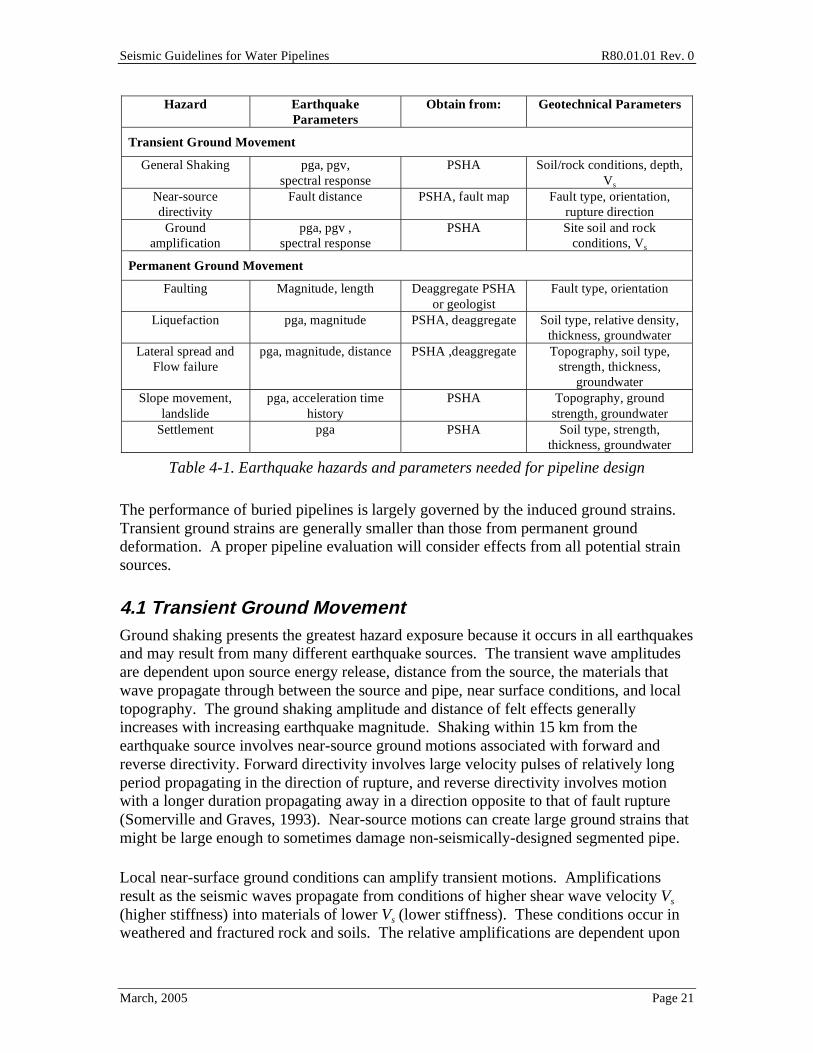
Transient ground movement describes the shaking hazard by waves propagating from the energy source and the amplifications due to surface and near surface ground conditions and topography. Permanent ground movement describes the ground failures resulting from surface fault rupture, slope movements and landslides, liquefaction induced lateral spreading and flow failure, and differential settlement. Table 4-1 summarizes the transient and permanent ground movement hazards considered in these Guidelines that may damage water pipelines, the earthquake parameters needed for an engineering evaluation for each hazard, recommended methods for obtaining the earthquake parameters, and geotechnical parameters needed for a proper engineering evaluation of the earthquake hazard.
The purpose of this section is to identify the earthquake hazards a water pipeline may be exposed to that are of concern, provide a general description of how the hazard affects pipelines, and define the parameters needed to quantify the earthquake hazards for engineering design. The following sections provide recommendations for performing geotechnical investigations and evaluations to assess the true exposure and level of concern, if any, different earthquake hazards have on water pipelines.
Seismic Guidelines for Water Pipelines R80.01.01 Rev. 0
March, 2005 Page 21
Hazard Earthquake Parameters
Obtain from: Geotechnical Parameters
Transient Ground Movement
General Shaking pga, pgv, spectral response
PSHA Soil/rock conditions, depth, Vs
Near-source directivity
Fault distance PSHA, fault map Fault type, orientation, rupture direction
Ground amplification
pga, pgv , spectral response
PSHA Site soil and rock conditions, Vs
Permanent Ground Movement
Faulting Magnitude, length Deaggregate PSHA or geologist
Fault type, orientation
Liquefaction pga, magnitude PSHA, deaggregate Soil type, relative density, thickness, groundwater
Lateral spread and Flow failure
pga, magnitude, distance PSHA ,deaggregate Topography, soil type, strength, thickness,
groundwater Slope movement,
landslide pga, acceleration time
history PSHA Topography, ground
strength, groundwater Settlement pga PSHA Soil type, strength,
thickness, groundwater
Table 4-1. Earthquake hazards and parameters needed for pipeline design
The performance of buried pipelines is largely governed by the induced ground strains. Transient ground strains are generally smaller than those from permanent ground deformation. A proper pipeline evaluation will consider effects from all potential strain sources.
4.1 Transient Ground Movement Ground shaking presents the greatest hazard exposure because it occurs in all earthquakes and may result from many different earthquake sources. The transient wave amplitudes are dependent upon source energy release, distance from the source, the materials that wave propagate through between the source and pipe, near surface conditions, and local topography. The ground shaking amplitude and distance of felt effects generally increases with increasing earthquake magnitude. Shaking within 15 km from the earthquake source involves near-source ground motions associated with forward and reverse directivity. Forward directivity involves large velocity pulses of relatively long period propagating in the direction of rupture, and reverse directivity involves motion with a longer duration propagating away in a direction opposite to that of fault rupture (Somerville and Graves, 1993). Near-source motions can create large ground strains that might be large enough to sometimes damage non-seismically-designed segmented pipe.
Local near-surface ground conditions can amplify transient motions. Amplifications result as the seismic waves propagate from conditions of higher shear wave velocity Vs (higher stiffness) into materials of lower Vs (lower stiffness). These conditions occur in weathered and fractured rock and soils. The relative amplifications are dependent upon
Seismic Guidelines for Water Pipelines R80.01.01 Rev. 0
March, 2005 Page 22
the relative Vs (Schnable, 1972). Weaker soils may deamplify ground motions when the ground strains exceed the available soil strength (Idriss, 1990). Large transient strains may result at interfaces of different materials, called impedance boundaries, due to changes in wave propagation speed.
4.2 Liquefaction Liquefaction is the loss of shear strength, and corresponding reduction in effective stress, in saturated or nearly saturated soils due to shaking induced pore water pressure increases. It is the effects of liquefaction that pose a hazard to pipelines, rather than the actual liquefaction phenomena. Pore water pressure increases can impose buoyancy on buried pipelines, which if not properly accounted for may lead to pipe floatation and possible damage.
The loss of soil shear strength can lead to large permanent ground strains. Permanent ground movements are manifested through lateral spreading, flow failure, and settlement. Lateral spreading is the down slope movement occurring when cyclic inertial loads exceed the reduced effective soil strength and is generally associated with shallow surface ground slopes (as low as a fraction of a percent slope). Flow failure is a slope instability problem resulting when the static shear stresses in sloping ground exceed the liquefied soil residual strength. Liquefaction induced settlements are generally larger than non-liquefaction settlements. Reductions in soil bearing strength may also cause problems for above ground pipes.
Liquefaction may also induce pipe flotation, especially empty pipes commonly used in sewer systems. Flotation has not been a common source of damage for water pipelines, as they are rarely (if ever) empty.
4.3 Permanent Ground Movement Permanent ground movements pose the greatest hazard for pipelines, even though they are more localized and involve less exposure to pipelines than transient movements. The significance of this hazard is related to the large ground strains resulting from permanent movements. Strains induced by permanent ground deformation will be the largest at the movement boundaries. For liquefaction, this occurs at the interface between liquefied and non-liquefied materials; for faulting it occurs at the primary trace of surface rupture; for landslides it occurs at slide boundaries; for settlement the greatest hazard results at locations of greatest differential settlement.
Surface faulting may occur on earthquake-generating faults or as sympathetic movement on nearby faults. Fault rupture generally occurs over a zone with largest movements resulting on a main trace and other fractures with movements of concern occurring at distances away from the main trace. The total magnitude of surface rupture and width of rupture zone is a function of earthquake magnitude, with larger movements generally occurring with larger magnitudes, and with the zone of deformation usually dependent on the local nature of the fault.

Seismic Guidelines for Water Pipelines R80.01.01 Rev. 0
March, 2005 Page 23
Slopes stable under static conditions may be destabilized under seismic shaking as a result of induced inertial forces. The steeper the slope and weaker the resisting planes, the more susceptible to movement the slope becomes. The presence of groundwater increases the slope movement potential through increased pore water pressure and reduced effective stress. Landslides generally refer to a broad category of failures including earth slides, rock falls, slumps, and debris flows. Earth slides may result in movements from a few millimeters to several tens to hundreds of meters. Smaller deformations are generally referred to as slope movements and larger movements as slope failures or just landslides. Rock falls are rarely a problem for buried pipes.
Settlement results from the densification of relatively loose, partially saturated or dry granular soils. Settlement increases with decreasing relative density and fines content. Settlement also occurs as a consequence of liquefaction in saturated granular soil, and will again increase with decreasing relative density and fines content (Ishihara and Yoshimine, 1995; Tokimatsu and Seed, 1987). Settlement resulting from densification is the surface manifestation of volumetric strain, which is directly related to the total thickness of loose and/or liquefiable soil layers. The hazard to pipelines occurs where the greatest differential settlement results.
Settlement may also occur as a result of subsurface erosion and ejection of soil at sand boils, fissures, and cracks in the ground overlying soil subjected to liquefaction. This type of settlement is related to the localized loss of material through ejection and venting of particles carried by water at elevated pressure. It may be accompanied by large differential settlement in the form of surface depressions and sink-hole-like manifestations of surface movement. Such deformation generally occurs in soil deposits subjected to prolonged and severe liquefaction. It involves larger levels of settlement than those associated with densification, as described above. Sometimes, movement of this sort is accompanied by large lateral displacements, which represent a more severe condition of deformation for underground pipelines. Under these conditions then, it will generally be appropriate to concentrate on the effects of large lateral soil movement, as addressed under Section 4.2.1.
Soil deformations due to soil failure (including weak clay deformations in peat, bay mud and similar situations) may also occur.
4.4 Seismic Hazard Analysis The definition of the earthquake hazards along a pipeline alignment must be performed as part of the seismic design process. The pipe alignment must be assessed to determine which of the earthquake hazards described in Sections 4.0 to 4.3 and in the commentary may affect the pipes seismic performance. An analysis of the hazards may be performed using probabilistic or deterministic seismic hazard analyses (PSHA and DSHA, respectively). Advantages and disadvantages to PSHA and DSHA in pipeline evaluations are presented in the commentary. The PSHA is used in these Guidelines for defining the hazard for single pipes extending over relatively short distances.
Seismic Guidelines for Water Pipelines R80.01.01 Rev. 0
March, 2005 Page 24
DSHA is useful when examining the performance of a complete pipeline network over a spatially large area. A "scenario" earthquake is an example of a DSHA. For spatially distributed pipeline systems, the PGA (as well as SA, PGV, PGD) at one site will be different from the PGA at some distant site, all associated with a particular scenario earthquake. For this reason, water utilities often resort to study using deterministic "earthquake scenarios" rather than probabilistic earthquakes. For larger water utilities that cover areas of hundreds of square miles, use of earthquake scenarios for evaluations (and sometimes design) can be a suitable approach. For smaller water utilities that cover a few tens of square miles, or for some situations in eastern United States where ground motions vary little in intensity over wide areas, then a probabilistic-based approach (i.e., a return-period approach) will be almost the same as a deterministic approach. For these Guidelines, we adopt a probabilistic approach, with the understanding that the user could adjust to a deterministic approach, as long as the intended performance (C3.2.3.7) of the pipeline network is achieved.
4.4.1 Probabilistic Seismic Hazard Analysis (PSHA)
Results of the PSHA will provide a consistent set of seismic design parameters having a uniform probability that each parameter will not be exceeded. As shown in Table 4-1, many seismic design parameters can be obtained from a PSHA. The USGS has an interactive deaggregation web page for performing site-specific4 PSHA, which is accessible on the World Wide Web at: http://eqint.cr.usgs.gov and is recommended for use with these Guidelines. The user can replace the USGS PSHA information with user-developed corresponding information.
Figure 4-1 shows the USGS data entry page. A PSHA may be performed for a pipeline by inputting the following information:
1. Site name. 2. Site coordinates (latitude, longitude). 3. Selection of return period. 4. Selection of pga or spectral acceleration frequency.
4 The PSHA values on the USGS web site are calculated at specific latitude/longitude pairs. Thus,
the term "site-specific" is not quite rigorous if the user inputs a latitude/longitude pair that is not atop one of the calculated values, as the USGS web site does interpolation for intermediate locations. Usually, the results from the USGS web site will be within 10 percent of a true site-specific calculation. Also, the calculation procedure on the USGS web site is based on data and methodologies that may become outdated over time, as new information is developed with regards to fault activity, fault location, attenuation models, and other facets of a truly site-specific calculation. A qualified professional can perform a PSHA and use that result rather than the USGS web site result.
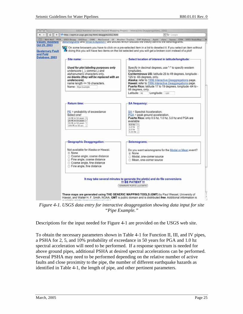
Seismic Guidelines for Water Pipelines R80.01.01 Rev. 0
March, 2005 Page 25
Figure 4-1. USGS data entry for interactive deaggregation showing data input for site
“Pipe Example.”
Descriptions for the input needed for Figure 4-1 are provided on the USGS web site.
To obtain the necessary parameters shown in Table 4-1 for Function II, III, and IV pipes, a PSHA for 2, 5, and 10% probability of exceedance in 50 years for PGA and 1.0 hz spectral acceleration will need to be performed. If a response spectrum is needed for above ground pipes, additional PSHA at desired spectral accelerations can be performed. Several PSHA may need to be performed depending on the relative number of active faults and close proximity to the pipe, the number of different earthquake hazards as identified in Table 4-1, the length of pipe, and other pertinent parameters.
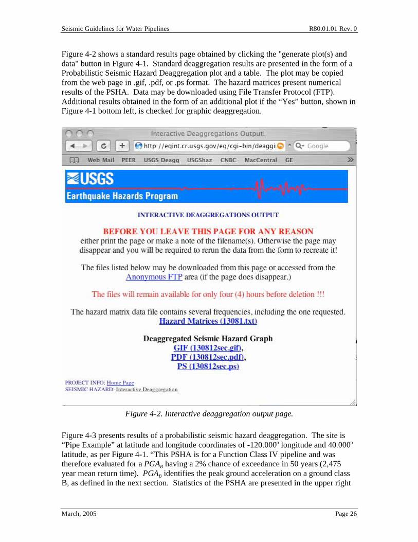
Seismic Guidelines for Water Pipelines R80.01.01 Rev. 0
March, 2005 Page 26
Figure 4-2 shows a standard results page obtained by clicking the "generate plot(s) and data" button in Figure 4-1. Standard deaggregation results are presented in the form of a Probabilistic Seismic Hazard Deaggregation plot and a table. The plot may be copied from the web page in .gif, .pdf, or .ps format. The hazard matrices present numerical results of the PSHA. Data may be downloaded using File Transfer Protocol (FTP). Additional results obtained in the form of an additional plot if the “Yes” button, shown in Figure 4-1 bottom left, is checked for graphic deaggregation.
Figure 4-2. Interactive deaggregation output page.
Figure 4-3 presents results of a probabilistic seismic hazard deaggregation. The site is “Pipe Example” at latitude and longitude coordinates of -120.000o longitude and 40.000o latitude, as per Figure 4-1. “This PSHA is for a Function Class IV pipeline and was therefore evaluated for a PGAB having a 2% chance of exceedance in 50 years (2,475 year mean return time). PGAB identifies the peak ground acceleration on a ground class B, as defined in the next section. Statistics of the PSHA are presented in the upper right
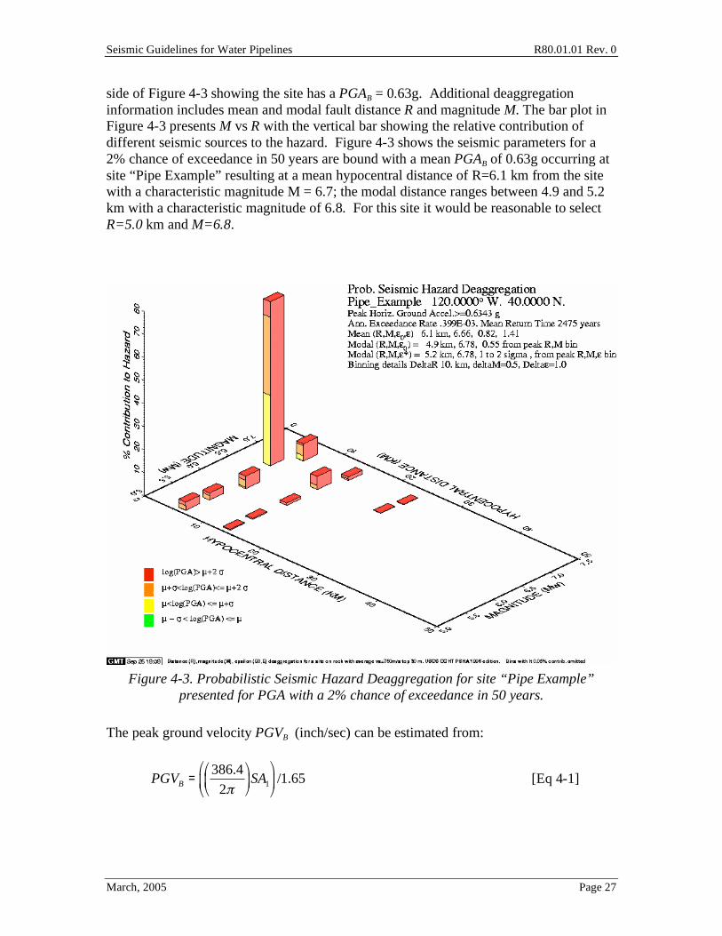
Seismic Guidelines for Water Pipelines R80.01.01 Rev. 0
March, 2005 Page 27
side of Figure 4-3 showing the site has a PGAB = 0.63g. Additional deaggregation information includes mean and modal fault distance R and magnitude M. The bar plot in Figure 4-3 presents M vs R with the vertical bar showing the relative contribution of different seismic sources to the hazard. Figure 4-3 shows the seismic parameters for a 2% chance of exceedance in 50 years are bound with a mean PGAB of 0.63g occurring at site “Pipe Example” resulting at a mean hypocentral distance of R=6.1 km from the site with a characteristic magnitude M = 6.7; the modal distance ranges between 4.9 and 5.2 km with a characteristic magnitude of 6.8. For this site it would be reasonable to select R=5.0 km and M=6.8.
Figure 4-3. Probabilistic Seismic Hazard Deaggregation for site “Pipe Example”
presented for PGA with a 2% chance of exceedance in 50 years.
The peak ground velocity PGVB (inch/sec) can be estimated from:
PGVB =386.4
2
SA1
/1.65 [Eq 4-1]
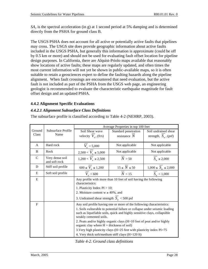
Seismic Guidelines for Water Pipelines R80.01.01 Rev. 0
March, 2005 Page 28
SA1 is the spectral acceleration (in g) at 1 second period at 5% damping and is determined directly from the PSHA for ground class B.
The USGS PSHA does not account for all active or potentially active faults that pipelines may cross. The USGS site does provide geographic information about active faults included in the USGS PSHA, but generally this information is approximate (could be off by 0.5 km or more) and should not be used for evaluating fault offset location for pipeline design purposes. In California, there are Alquist-Priolo maps available that reasonably show locations of active faults; these maps are regularly updated, and often times the most current information will not yet be shown in public-available maps, so it is often suitable to retain a geosciences expert to define the faulting hazards along the pipeline alignment. When fault crossings are encountered that need evaluation, but the active fault is not included as part of the PSHA from the USGS web page, an engineering geologist is recommended to evaluate the characteristic earthquake magnitude for fault offset design and an updated PSHA.
4.4.2 Alignment Specific Evaluations
4.4.2.1 Alignment Subsurface Class Definitions
The subsurface profile is classified according to Table 4-2 (NEHRP, 2003).
Average Properties in top 100 feet Ground Class
Subsurface Profile
Name Soil Shear wave
velocity Vs , (ft/s)
Standard penetration
resistance N
Soil undrained shear
strength, Su , (psf)
A Hard rock Vs > 5,000 Not applicable Not applicable
B Rock 2,500 < Vs 5,000 Not applicable Not applicable
C Very dense soil and soft rock
1,200 < Vs 2,500 N > 50 Su 2,000
D Stiff soil profile 600 Vs 1,200 15 N 50 1,000 Su 2,000
E Soft soil profile Vs < 600 N < 15 Su < 1,000
E Any profile with more than 10 feet of soil having the following characteristics: 1. Plasticity Index PI > 10; 2. Moisture content w 40%, and
3. Undrained shear strength Su < 500 psf
F Any soil profile having one or more of the following characteristics: 1. Soils vulnerable to potential failure or collapse under seismic loading such as liquefiable soils, quick and highly sensitive clays, collapsible weakly cemented soils. 2. Peats and/or highly organic clays (H>10 feet of peat and/or highly organic clay where H = thickness of soil) 3.Very high plasticity clays (H>25 feet with plasticity index PI>75 4. Very thick soft/medium stiff clays (H>120 ft)
Table 4-2. Ground class definitions
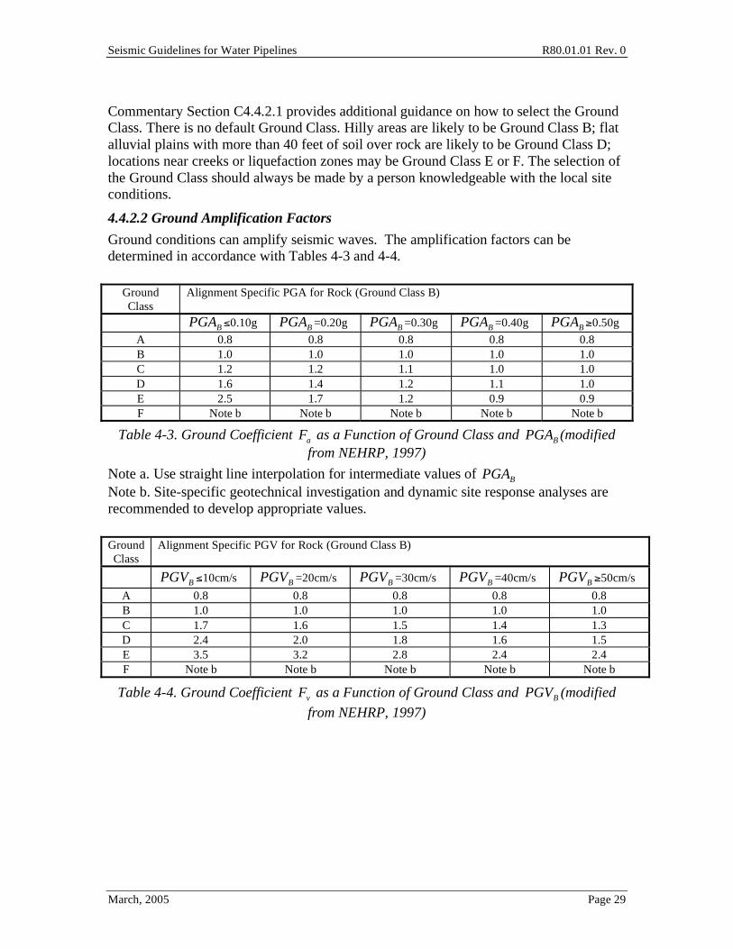
Seismic Guidelines for Water Pipelines R80.01.01 Rev. 0
March, 2005 Page 29
Commentary Section C4.4.2.1 provides additional guidance on how to select the Ground Class. There is no default Ground Class. Hilly areas are likely to be Ground Class B; flat alluvial plains with more than 40 feet of soil over rock are likely to be Ground Class D; locations near creeks or liquefaction zones may be Ground Class E or F. The selection of the Ground Class should always be made by a person knowledgeable with the local site conditions.
4.4.2.2 Ground Amplification Factors
Ground conditions can amplify seismic waves. The amplification factors can be determined in accordance with Tables 4-3 and 4-4.
Ground Class
Alignment Specific PGA for Rock (Ground Class B)
PGAB 0.10g PGAB =0.20g PGAB =0.30g PGAB =0.40g PGAB 0.50g
A 0.8 0.8 0.8 0.8 0.8 B 1.0 1.0 1.0 1.0 1.0 C 1.2 1.2 1.1 1.0 1.0 D 1.6 1.4 1.2 1.1 1.0 E 2.5 1.7 1.2 0.9 0.9 F Note b Note b Note b Note b Note b
Table 4-3. Ground Coefficient Fa as a Function of Ground Class and PGAB (modified from NEHRP, 1997)
Note a. Use straight line interpolation for intermediate values of PGAB Note b. Site-specific geotechnical investigation and dynamic site response analyses are recommended to develop appropriate values.
Ground Class
Alignment Specific PGV for Rock (Ground Class B)
B
PGV 10cm/s B
PGV =20cm/s B
PGV =30cm/s B
PGV =40cm/s B
PGV 50cm/s
A 0.8 0.8 0.8 0.8 0.8 B 1.0 1.0 1.0 1.0 1.0 C 1.7 1.6 1.5 1.4 1.3 D 2.4 2.0 1.8 1.6 1.5 E 3.5 3.2 2.8 2.4 2.4 F Note b Note b Note b Note b Note b
Table 4-4. Ground Coefficient v
F as a Function of Ground Class and B
PGV (modified
from NEHRP, 1997)
Seismic Guidelines for Water Pipelines R80.01.01 Rev. 0
March, 2005 Page 30
4.4.2.3 Near-source factors
Near source factors to account for directivity, fault normal, hanging wall or other such effects need not be used when estimating the ground motions using the PSHA approach described in Section 4.4.1, 4.4.2.1 and 4.4.2.2. The uncertainties associated with these effects are already included in the standard error terms that are factored into the PSHA.
4.4.2.4 Alignment specific design ground motion parameters
The design peak ground acceleration PGA and velocity PGV and spectral acceleration at 1 second SA1 are determined from:
PGA = Fa PGAB [Eq 4-2]
PGV = Fv PGVB [Eq 4-3]
SA1 = Fv SA1B [Eq 4-4]
where Fa and Fv are from Tables 4-3 and 4-4.
4.4.2.5 Design Response Spectra
Figure 4-4 shows the response spectrum recommended for design of above ground pipes having a fundamental natural period T. For periods T To, the design spectral response acceleration Sa is determined by:
Sa =1.5PGA
To
T + PGA T0 = 0.08SAl
PGA [Eq 4-5]
For T Ts, Sa is determined by:
Sa =SAl
T Ts =
SAl
2.5PGA [Eq 4-6]
Sa = 2.5PGA for To T Ts. [Eq 4-7]
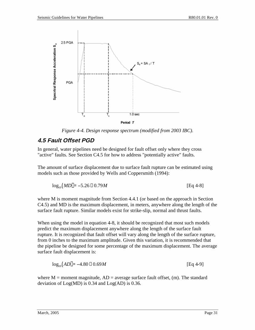
Seismic Guidelines for Water Pipelines R80.01.01 Rev. 0
March, 2005 Page 31
Figure 4-4. Design response spectrum (modified from 2003 IBC).
4.5 Fault Offset PGD In general, water pipelines need be designed for fault offset only where they cross "active" faults. See Section C4.5 for how to address "potentially active" faults.
The amount of surface displacement due to surface fault rupture can be estimated using models such as those provided by Wells and Coppersmith (1994):
log10 MD( ) = 5.26 + 0.79M [Eq 4-8]
where M is moment magnitude from Section 4.4.1 (or based on the approach in Section C4.5) and MD is the maximum displacement, in meters, anywhere along the length of the surface fault rupture. Similar models exist for strike-slip, normal and thrust faults.
When using the model in equation 4-8, it should be recognized that most such models predict the maximum displacement anywhere along the length of the surface fault rupture. It is recognized that fault offset will vary along the length of the surface rupture, from 0 inches to the maximum amplitude. Given this variation, it is recommended that the pipeline be designed for some percentage of the maximum displacement. The average surface fault displacement is:
log10 AD( ) = 4.80 + 0.69M [Eq 4-9]
where M = moment magnitude, AD = average surface fault offset, (m). The standard deviation of Log(MD) is 0.34 and Log(AD) is 0.36.

Seismic Guidelines for Water Pipelines R80.01.01 Rev. 0
March, 2005 Page 32
It should also be noted that fault offset models of the type in equations 4-8 or 4-9 provide a median estimate of the maximum (4-8) or average (4-9) displacement along the length of the fault for a given magnitude earthquake. A dispersion estimate of the amount of fault offset is usually provided with the model.
All Function Class III or IV pipelines crossing active faults should be designed for fault movement. A fault is considered active if it has moved within the past 11,000 years. All active fault crossings must be considered along the pipeline regardless of whether the fault was included in the ground shaking hazard evaluation. Any fault not identified as being inactive is considered to be active unless it can be shown that it is not capable of a magnitude 6.25 or larger earthquake with return period of 11,000 years or less.
For strike-slip faults, Wells and Coppersmith (1994) provide the following relationships:
Log10 MD( ) = 7.03+1.03M
Log10 AD( ) = 6.32 + 0.90M [Eq 4-10]
where M = moment magnitude, MD = maximum horizontal surface fault offset (m), AD = average horizontal surface fault offset, (m).
All Function III and IV pipelines, including redundant pipes reclassified to Function II using Table 3-3, crossing active faults can be designed for fault movement in accordance with Table 4-5. All other Function II pipelines are recommended to be designed for active fault movement in accordance with Table 4-5 or have the capability to be isolated from Function III and IV pipes in the event of a fault rupture.
Pipe Function Design Movement PGD
II AD
III 1.5*AD
IV 2.3*AD
Table 4-5. Design recommendations for fault movement
Note; for fault offset, we recommend selecting the moment magnitude based on the 475 year event for all Function Class II, III or IV, and then increasing the design offset per the simple multipliers in Table 4-5. An alternate approach for selecting the design movement is presented in Section C4.5. It is also necessary to consider the spatial variation in application of the design offset to the pipeline. Figure 4-5 illustrates this. Based on site characterization, it will usually be found for strike slip faults that the primary fault offset might occur anywhere within a "Zone A", with some minor movements occurring in adjacent "Zones B". Four scenarios of fault offset patterns are shown in Figure 4-5:
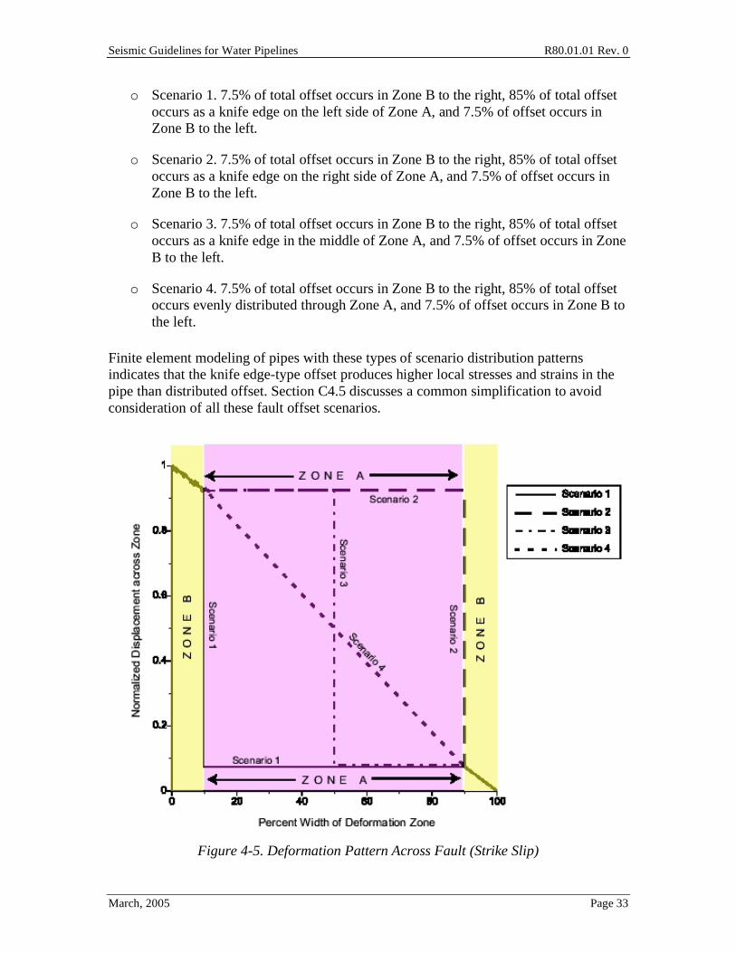
Seismic Guidelines for Water Pipelines R80.01.01 Rev. 0
March, 2005 Page 33
o Scenario 1. 7.5% of total offset occurs in Zone B to the right, 85% of total offset occurs as a knife edge on the left side of Zone A, and 7.5% of offset occurs in Zone B to the left.
o Scenario 2. 7.5% of total offset occurs in Zone B to the right, 85% of total offset occurs as a knife edge on the right side of Zone A, and 7.5% of offset occurs in Zone B to the left.
o Scenario 3. 7.5% of total offset occurs in Zone B to the right, 85% of total offset occurs as a knife edge in the middle of Zone A, and 7.5% of offset occurs in Zone B to the left.
o Scenario 4. 7.5% of total offset occurs in Zone B to the right, 85% of total offset occurs evenly distributed through Zone A, and 7.5% of offset occurs in Zone B to the left.
Finite element modeling of pipes with these types of scenario distribution patterns indicates that the knife edge-type offset produces higher local stresses and strains in the pipe than distributed offset. Section C4.5 discusses a common simplification to avoid consideration of all these fault offset scenarios.
Figure 4-5. Deformation Pattern Across Fault (Strike Slip)
Seismic Guidelines for Water Pipelines R80.01.01 Rev. 0
March, 2005 Page 34
An engineering geologist should provide input as to the width of Zones A and B for each trace of the fault.
4.6 Liquefaction The potential liquefaction induced damage to pipelines is assessed in the following stages:
Stage 1. Assess the soil susceptibility to liquefaction. Stage 2. Evaluate the potential for liquefaction triggering. Stage 3. Evaluate the probability of liquefaction occurrence. Stage 4. Evaluate hazards resulting from liquefaction. Stage 5. Evaluate the liquefaction hazard potential effects on pipelines. Stage 6. Evaluate mitigation alternatives for liquefaction hazard effects.
This section assesses the susceptibility to liquefaction and makes reference to the evaluation for the potential for liquefaction triggering and the determination of probability of occurrence. The remaining steps are performed in following sections of these Guidelines along with other hazards.
A pipe is located within a liquefaction hazard zone if any soil layers lying below the pipe alignment are considered liquefiable. The pipe is not required to be placed within a liquefiable layer to be subject to a liquefaction ground movement hazard. Pipes placed below all liquefiable soils are not considered to be subject to liquefaction hazards. A geotechnical engineer and engineering geologist are recommended to be consulted for evaluation of potential liquefaction hazards.
Liquefaction susceptibility should be assessed using historical precedent where liquefaction is known to occur in the past. Any location where liquefaction has occurred in the past must be expected to have liquefaction in the future. A preliminary regional assessment of soil susceptibility to liquefaction may be based on geologic age and mode of deposition for surface deposits. Table 4-7 presents a summary of different soil susceptibilities to liquefaction from Youd and Perkins (1978).
Some communities have had liquefaction susceptibility maps developed. Commentary Section C4.6.1 describes how these maps should be prepared. Assuming that a suitable map exists, the design PGD (both horizontal and vertical) for a particular pipe can be calculated in a few minutes using equations [C4-6] through [C4-10], and Tables C4-3 through C4-7.
If suitable liquefaction hazard maps for the pipeline (or entire water utility) are not available, then the following sections describe how to calculate the PGD for horizontal movement using Table 4-7, in combination with only cursory knowledge of the sedimentary deposits that the pipe traverses (Table 4-6), and using equation 4-11 and Table 4-8. This procedure greatly simplifies the process and introduces substantial uncertainty. It will generally over predict the likelihood of occurrence and magnitude of
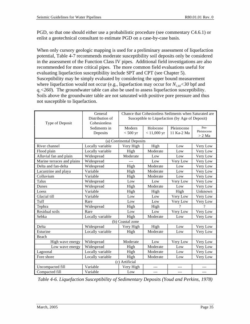
Seismic Guidelines for Water Pipelines R80.01.01 Rev. 0
March, 2005 Page 35
PGD, so that one should either use a probabilistic procedure (see commentary C4.6.1) or enlist a geotechnical consultant to estimate PGD on a case-by-case basis.
When only cursory geologic mapping is used for a preliminary assessment of liquefaction potential, Table 4-7 recommends moderate susceptibility soil deposits only be considered in the assessment of the Function Class IV pipes. Additional field investigations are also recommended for more critical pipes. The more common field evaluations useful for evaluating liquefaction susceptibility include SPT and CPT (see Chapter 5). Susceptibility may be simply evaluated by considering the upper bound measurement where liquefaction would not occur (e.g., liquefaction may occur for N1,60<30 bpf and qc<260). The groundwater table can also be used to assess liquefaction susceptibility. Soils above the groundwater table are not saturated with positive pore pressure and thus not susceptible to liquefaction.
Type of Deposit
General Distribution of Cohesionless
Chance that Cohesionless Sediments when Saturated are Susceptible to Liquefaction (by Age of Deposit)
Sediments in Deposits
Modern < 500 yr
Holocene < 11,000 yr
Pleistocene 11 Ka-2 Ma
Pre-Pleistocene > 2 Ma
(a) Continental Deposits River channel Locally variable Very High High Low Very Low Flood plain Locally variable High Moderate Low Very Low Alluvial fan and plain Widespread Moderate Low Low Very Low Marine terraces and plains Widespread --- Low Very Low Very Low Delta and fan-delta Widespread High Moderate Low Very Low Lacustrine and playa Variable High Moderate Low Very Low Colluvium Variable High Moderate Low Very Low Talus Widespread Low Low Very Low Very Low Dunes Widespread High Moderate Low Very Low Loess Variable High High High Unknown Glacial till Variable Low Low Very Low Very Low Tuff Rare Low Low Very Low Very Low Tephra Widespread High High ? ? Residual soils Rare Low Low Very Low Very Low Sebka Locally variable High Moderate Low Very Low
(b) Coastal zone Delta Widespread Very High High Low Very Low Esturine Locally variable High Moderate Low Very Low Beach
High wave energy Widespread Moderate Low Very Low Very Low Low wave energy Widespread High Moderate Low Very Low
Lagoonal Locally variable High Moderate Low Very Low Fore shore Locally variable High Moderate Low Very Low
(c) Artificial Uncompacted fill Variable Very High --- --- --- Compacted fill Variable Low --- --- ---
Table 4-6. Liquefaction Susceptibility of Sedimentary Deposits (Youd and Perkins, 1978)
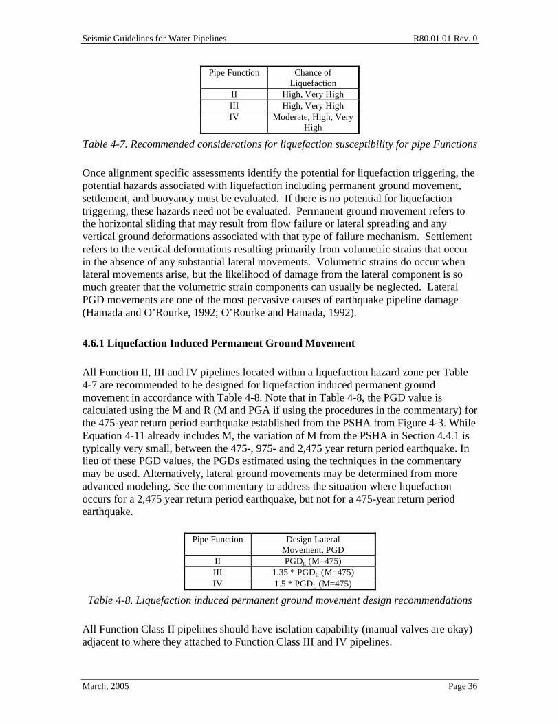
Seismic Guidelines for Water Pipelines R80.01.01 Rev. 0
March, 2005 Page 36
Pipe Function Chance of Liquefaction
II High, Very High III High, Very High IV Moderate, High, Very
High
Table 4-7. Recommended considerations for liquefaction susceptibility for pipe Functions
Once alignment specific assessments identify the potential for liquefaction triggering, the potential hazards associated with liquefaction including permanent ground movement, settlement, and buoyancy must be evaluated. If there is no potential for liquefaction triggering, these hazards need not be evaluated. Permanent ground movement refers to the horizontal sliding that may result from flow failure or lateral spreading and any vertical ground deformations associated with that type of failure mechanism. Settlement refers to the vertical deformations resulting primarily from volumetric strains that occur in the absence of any substantial lateral movements. Volumetric strains do occur when lateral movements arise, but the likelihood of damage from the lateral component is so much greater that the volumetric strain components can usually be neglected. Lateral PGD movements are one of the most pervasive causes of earthquake pipeline damage (Hamada and O’Rourke, 1992; O’Rourke and Hamada, 1992).
4.6.1 Liquefaction Induced Permanent Ground Movement
All Function II, III and IV pipelines located within a liquefaction hazard zone per Table 4-7 are recommended to be designed for liquefaction induced permanent ground movement in accordance with Table 4-8. Note that in Table 4-8, the PGD value is calculated using the M and R (M and PGA if using the procedures in the commentary) for the 475-year return period earthquake established from the PSHA from Figure 4-3. While Equation 4-11 already includes M, the variation of M from the PSHA in Section 4.4.1 is typically very small, between the 475-, 975- and 2,475 year return period earthquake. In lieu of these PGD values, the PGDs estimated using the techniques in the commentary may be used. Alternatively, lateral ground movements may be determined from more advanced modeling. See the commentary to address the situation where liquefaction occurs for a 2,475 year return period earthquake, but not for a 475-year return period earthquake.
Pipe Function Design Lateral Movement, PGD
II PGDL (M=475) III 1.35 * PGDL (M=475) IV 1.5 * PGDL (M=475)
Table 4-8. Liquefaction induced permanent ground movement design recommendations
All Function Class II pipelines should have isolation capability (manual valves are okay) adjacent to where they attached to Function Class III and IV pipelines.
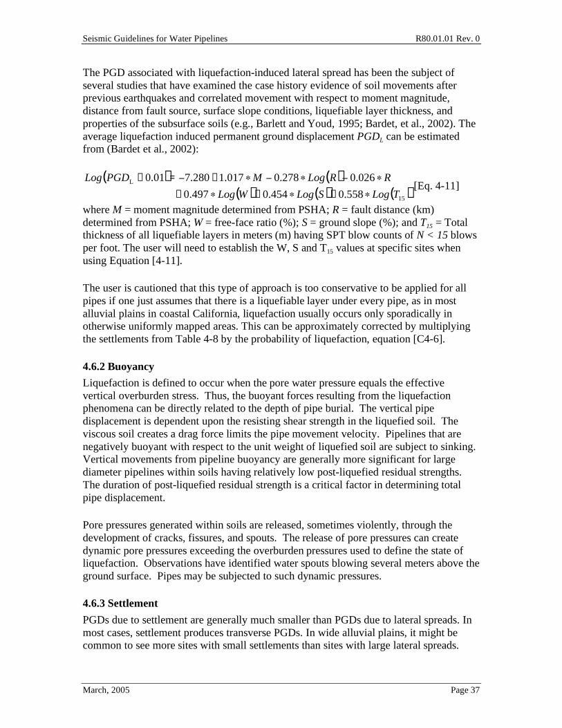
Seismic Guidelines for Water Pipelines R80.01.01 Rev. 0
March, 2005 Page 37
The PGD associated with liquefaction-induced lateral spread has been the subject of several studies that have examined the case history evidence of soil movements after previous earthquakes and correlated movement with respect to moment magnitude, distance from fault source, surface slope conditions, liquefiable layer thickness, and properties of the subsurface soils (e.g., Barlett and Youd, 1995; Bardet, et al., 2002). The average liquefaction induced permanent ground displacement PGDL can be estimated from (Bardet et al., 2002):
( ) ( )
( ) ( ) ( )15
L
558.0454.0497.0
026.0278.0017.1280.701.0
TLogSLogWLog
RRLogMPGDLog
+++
+=+ [Eq. 4-11]
where M = moment magnitude determined from PSHA; R = fault distance (km) determined from PSHA; W = free-face ratio (%); S = ground slope (%); and T15 = Total thickness of all liquefiable layers in meters (m) having SPT blow counts of N < 15 blows per foot. The user will need to establish the W, S and T15 values at specific sites when using Equation [4-11].
The user is cautioned that this type of approach is too conservative to be applied for all pipes if one just assumes that there is a liquefiable layer under every pipe, as in most alluvial plains in coastal California, liquefaction usually occurs only sporadically in otherwise uniformly mapped areas. This can be approximately corrected by multiplying the settlements from Table 4-8 by the probability of liquefaction, equation [C4-6].
4.6.2 Buoyancy
Liquefaction is defined to occur when the pore water pressure equals the effective vertical overburden stress. Thus, the buoyant forces resulting from the liquefaction phenomena can be directly related to the depth of pipe burial. The vertical pipe displacement is dependent upon the resisting shear strength in the liquefied soil. The viscous soil creates a drag force limits the pipe movement velocity. Pipelines that are negatively buoyant with respect to the unit weight of liquefied soil are subject to sinking. Vertical movements from pipeline buoyancy are generally more significant for large diameter pipelines within soils having relatively low post-liquefied residual strengths. The duration of post-liquefied residual strength is a critical factor in determining total pipe displacement.
Pore pressures generated within soils are released, sometimes violently, through the development of cracks, fissures, and spouts. The release of pore pressures can create dynamic pore pressures exceeding the overburden pressures used to define the state of liquefaction. Observations have identified water spouts blowing several meters above the ground surface. Pipes may be subjected to such dynamic pressures.
4.6.3 Settlement
PGDs due to settlement are generally much smaller than PGDs due to lateral spreads. In most cases, settlement produces transverse PGDs. In wide alluvial plains, it might be common to see more sites with small settlements than sites with large lateral spreads.
Seismic Guidelines for Water Pipelines R80.01.01 Rev. 0
March, 2005 Page 38
The performance of buried pipelines is much more seriously impacted due to PGDs along the longitudinal direction of the pipe than transverse to the pipe barrel. For this reason, in most cases specific design for transverse PGD is not required. However, for Function III and IV pipes, as well as Function II pipes where they enter structures of having a potential for differential settlement, or possibly for service laterals, it is important to design for transverse PGDs.
Table C4-5 in the commentary provides a simple way to estimate the PGD due to settlement due to liquefaction. Where appropriate, the user can estimate site-specific settlement when local subsurface conditions are known, and then estimate the volumetric strain changes on liquefiable layers given the particular level of shaking and duration. The user is cautioned that this type of approach is too conservative to be applied for all pipes if one just assumes that there is a liquefiable layer under every pipe, as in most alluvial plains in coastal California, liquefaction usually occurs only sporadically in otherwise uniformly mapped areas. This can be approximately corrected by multiplying the settlements from Table C4-5 by the probability of liquefaction, equation [C4-6].
4.6.4 Spatial Variation of Liquefaction PGDs
The width and length of the PGD zone has a strong influence on pipe response to PGD. Limited empirical observations suggest the following:
o The width of a lateral spread PGD zone varies from 250 to 2,000 feet.
o The length of a lateral spread PGD zone varies from a few tens of feet to about 800 feet.
o The direction of the PGD is generally in the downslope direction towards a free face.
o The peak PGD in the lateral spread zone is about 0.3% of the width of the zone, ±50%.
o The maximum of the PGD is usually closest to the free face, decreasing with distance from the free face. The free face is the location where the lateral spread flows towards; usually at a shoreline, and where the land slopes up from the shoreline.
The estimate of PGD from equation [4-11] represents the peak PGD in a lateral spread zone.
4.7 Landslide Assessment The potential landslide-induced damage to pipelines is assessed in the following stages:
Stage 1. Assess the ground susceptibility to landslides.
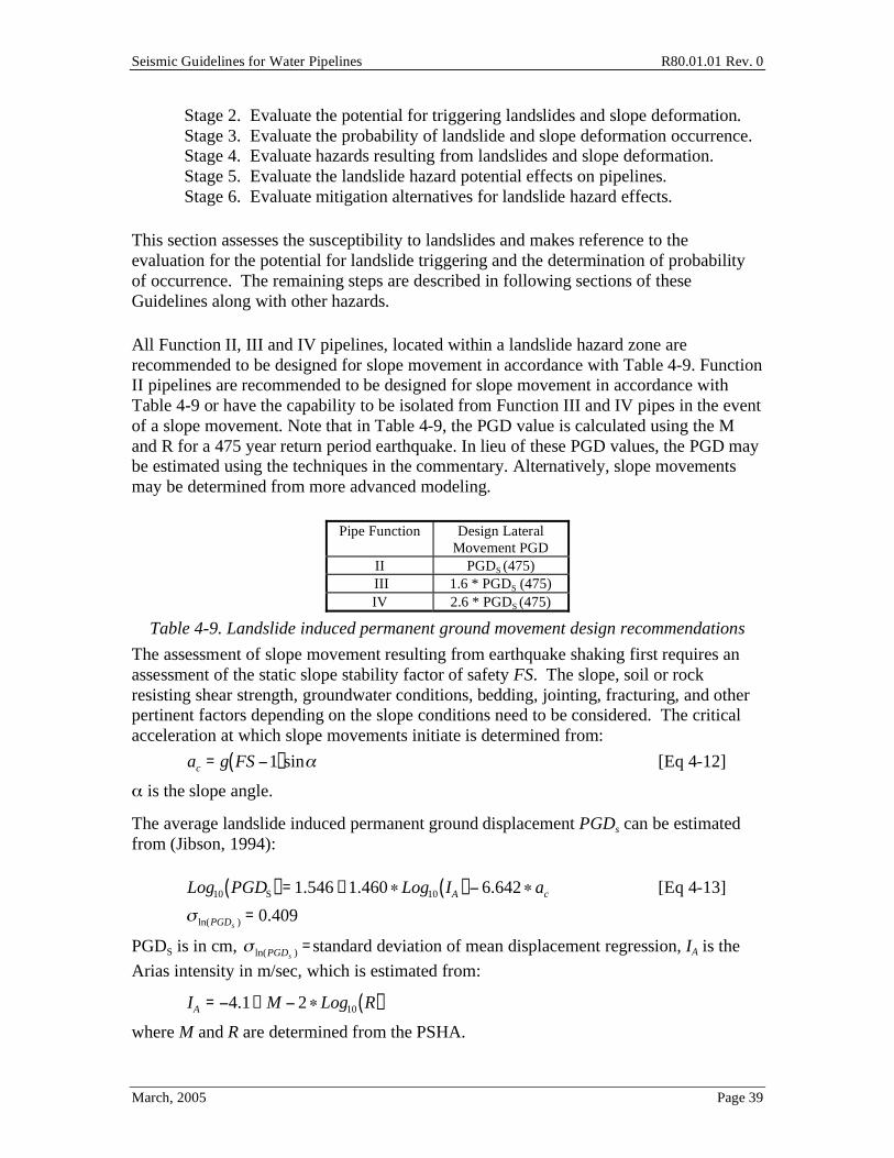
Seismic Guidelines for Water Pipelines R80.01.01 Rev. 0
March, 2005 Page 39
Stage 2. Evaluate the potential for triggering landslides and slope deformation. Stage 3. Evaluate the probability of landslide and slope deformation occurrence. Stage 4. Evaluate hazards resulting from landslides and slope deformation. Stage 5. Evaluate the landslide hazard potential effects on pipelines. Stage 6. Evaluate mitigation alternatives for landslide hazard effects.
This section assesses the susceptibility to landslides and makes reference to the evaluation for the potential for landslide triggering and the determination of probability of occurrence. The remaining steps are described in following sections of these Guidelines along with other hazards.
All Function II, III and IV pipelines, located within a landslide hazard zone are recommended to be designed for slope movement in accordance with Table 4-9. Function II pipelines are recommended to be designed for slope movement in accordance with Table 4-9 or have the capability to be isolated from Function III and IV pipes in the event of a slope movement. Note that in Table 4-9, the PGD value is calculated using the M and R for a 475 year return period earthquake. In lieu of these PGD values, the PGD may be estimated using the techniques in the commentary. Alternatively, slope movements may be determined from more advanced modeling.
Pipe Function Design Lateral Movement PGD
II PGDS (475) III 1.6 * PGDS (475) IV 2.6 * PGDS (475)
Table 4-9. Landslide induced permanent ground movement design recommendations
The assessment of slope movement resulting from earthquake shaking first requires an assessment of the static slope stability factor of safety FS. The slope, soil or rock resisting shear strength, groundwater conditions, bedding, jointing, fracturing, and other pertinent factors depending on the slope conditions need to be considered. The critical acceleration at which slope movements initiate is determined from:
ac = g FS 1( )sin [Eq 4-12]
is the slope angle.
The average landslide induced permanent ground displacement PGDs can be estimated from (Jibson, 1994):
Log10 PGDS( ) =1.546 +1.460 Log10 IA( ) 6.642 ac [Eq 4-13]
ln(PGDs ) = 0.409
PGDS is in cm, ln(PGDs ) =standard deviation of mean displacement regression, IA is the
Arias intensity in m/sec, which is estimated from:
IA = 4.1+ M 2 Log10 R( )
where M and R are determined from the PSHA.