Embed Size (px)
Citation preview

Tenth U.S. National Conference on Earthquake EngineeringFrontiers of Earthquake Engineering July 21-25, 2014 Anchorage, Alaska 10NCEE
SEISMIC EARTH PRESSURES ON INVERTED T-SHAPE RETAINING
STRUCTURES VIA DYNAMIC CENTRIFUGE TESTING
S. B. Jo1, J. G. Ha1, J. S. Lee2, D. S. Kim3
ABSTRACT A series of dynamic centrifuge tests were conducted to determine the dynamic response of an inverted T-shape cantilever retaining models subjected to earthquake motions. This paper demonstrates the discrepancy between hypothesis of Mononobe-Okabe method and actual behavior during earthquake through the assessment of test results. It was found that acceleration was amplified in a soil wedge behind retaining wall and seismic coefficient (kh) was not uniform. In pseudo-static method such as Mononobe-Okabe and Seed-Whitman method, dynamic earth pressure was determined by uniform seismic coefficient (kh) and acceleration amplified along the depth can cause an overestimation for dynamic earth pressure. For retaining wall allowed yielding, surface PGA in the free-field overestimate dynamic earth pressure due to the phase difference between dynamic earth pressure and moment of the wall. This phase difference was induced by inertial moment of the wall itself. In this study, 70% of maximum PGA provide appropriate upper bound for higher retaining wall. Moreover, distribution of dynamic earth pressure is a triangle shape and dynamic thrust is close to H/3, unlike 0.6H which was used in practical design of incremental dynamic earth pressure. And inertial moment of the wall itself has to be considered in the seismic design of retaining wall.
1Graduate Student Researcher, Dept. of Civil and Environmental Engineering, KAIST, Republic of Korea, Daejeon 2Assistant Professor, Dept. of Civil and Environmental Engineering, Wonkwang Univ., Republic of Korea, Iksan 3Professor, Dept. of Civil and Environmental Engineering, KAIST, Republic of Korea, Daejeon Jo SB, Ha JG, Lee JS and Kim DS. Seismic Earth Pressures on Inverted T-shape Retaining Structures via Dynamic Centrifuge Testing. Proceedings of the 10th National Conference in Earthquake Engineering, Earthquake Engineering Research Institute, Anchorage, AK, 2014.

Tenth U.S. National Conference on Earthquake EngineeringFrontiers of Earthquake Engineering July 21-25, 2014 Anchorage, Alaska 10NCEE
SEISMIC EARTH PRESSURES ON INVERTED T-SHAPE
RETAININING STRUCTURES VIA DYNAMIC CENTRIFUGE TESTING
S. B. Jo1, J. G. Ha1, J. S. Lee2 and D. S. Kim3
ABSTRACT A series of dynamic centrifuge tests were conducted to determine the dynamic response of an
inverted T-shape cantilever retaining models subjected to earthquake motions. This paper demonstrates the discrepancy between hypothesis of Mononobe-Okabe method and actual behavior during earthquake through the assessment of test results. It was found that acceleration was amplified in a soil wedge behind retaining wall and seismic coefficient (kh) was not uniform. In pseudo-static method such as Mononobe-Okabe and Seed-Whitman method, dynamic earth pressure was determined by uniform seismic coefficient (kh) and acceleration amplified along the depth can cause an overestimation for dynamic earth pressure. For retaining wall allowed yielding, surface PGA in the free-field overestimate dynamic earth pressure due to the phase difference between dynamic earth pressure and moment of the wall. This phase difference was induced by inertial moment of the wall itself. In this study, 70% of maximum PGA provide appropriate upper bound for higher retaining wall. Moreover, distribution of dynamic earth pressure is a triangle shape and dynamic thrust is close to H/3, unlike 0.6H which was used in practical design of incremental dynamic earth pressure. And inertial moment of the wall itself has to be considered in the seismic design of retaining wall.
Introduction
The pseudo-static limit equilibrium of evaluating the seismically induced lateral earth pressure on retaining structures has been initially suggested by Okabe [16] and Mononobe and Matsuo [14] in the 1920’s. Since then this method has been named by Mononobe-Okabe method (i.e. M-O method). M-O method have some assumptions for derivation and until a recent date many researchers have conducted theoretical and experimental research to reexamine the M-O method and evaluate the dynamic earth pressure. However, there are still many conflict conclusions among the researchers for M-O method.
Over time, the field observations and studies raise questions about the reliability of the M-O and/or Seed and Whitman [17] (i.e. S-W method) methodology. From field observation, there has been no indication that well-designed retaining structures experience significant
1Graduate Student Researcher, Dept. of Civil and Environmental Engineering, KAIST, Republic of Korea, Daejeon 2Assistant Professor, Dept. of Civil and Environmental Engineering, Wonkwang Univ., Republic of Korea, Iksan 3Professor, Dept. of Civil and Environmental Engineering, KAIST, Republic of Korea, Daejeon Jo S. B., Ha J. G., Lee J. S. and Kim D. S. Seismic Earth Pressures on Inverted T-shape Retaining Structures via Dynamic Centrifuge Testing. Proceedings of the 10th National Conference in Earthquake Engineering, Earthquake Engineering Research Institute, Anchorage, AK, 2014.

failures due to seismic loading, even in cases where the seismic load was not explicitly a design consideration [1, 5, 12, 17]. In addition, recently many researchers provided conflict conclusions that M-O method overestimate or underestimate the dynamic earth pressure during earthquake. Nakamura [14], Al Atik and Sitar [1] and Mikola [18] concluded that M-O method overestimate the dynamic earth pressure for U-shape and cantilever retaining wall by centrifuge test. It is induced by phase difference between inertial force of the wall and soil but M-O does not consider the inertial force of the wall. And they agreed that distribution of dynamic earth pressure is triangular through the experimental results. Green et al. [6] conducted numerical analysis and concluded that the dynamic earth pressure computed in the finite difference analyses did not correspond with those predicted by the M-O method. Because the flexibility of the wall and non-monolithic motion of the driving soil wedge violate assumptions of M-O method. Moreover, M-O method did not provide the position of dynamic thrust, on the other hand the S-W method recommends that dynamic thrust be applied at 0.6H. It means that distribution of dynamic earth pressure had an inverted triangular shape and this distribution results in a very large dynamic moment at the base of the retaining wall stem.
Meanwhile, M-O method use the maximum PGA as a seismic coefficient (kh) and it leads to very large forces at accelerations in excess of 0.6g. While, Seed and Whitman [17] (i.e. S-W method) overcome this shortcoming by approximating the increment of dynamic earth pressure linearly. However, both methods apply the uniform kh to the retained soil wedge for calculating dynamic earth pressure and there is no explicit criteria for location to determine kh of site PGA (e.g. PGA in foundation layer or surface of retained soil). Moreover, FEMA 750 [4] endorses the use of the M-O solution or the M-O solution as simplified by S-W method for “yielding walls”. However, while S-W method use 0.85 PGA as the effective acceleration and it has been a general practice to use 0.67 PGA for design [18]. Thus, the detailed consideration of kh is needed to evaluate the reliable dynamic earth pressure using M-O and S-W method.
Despite of these conflict issues, in practice, M-O method is considered as the easiest and appropriate method for seismic design of retaining structure. Thus, the purpose of this paper is to present centrifuge test results and suggest possible improvements of the currently used approaches about distribution of dynamic earth pressure and determination of kh. Two dynamic centrifuge experiments were performed to simulate inverted T-shape retaining walls and reexamine the previous research. Amplification of acceleration and dynamic earth pressure were measured and compared with hypothesis and estimation of M-O method. And inertial moment of the wall itself were accounted when the dynamic earth pressure was calculated from dynamic moment measured in the wall.
Experimental Procedure
Two dynamic centrifuge tests were performed with inverted T-shape retaining wall models. The experiments were conducted using the dynamic centrifuge at the KOCED Geo-Centrifuge Test Center at KAIST. The maximum capacity of the KAIST centrifuge with a 5 m radius is 2400 kg for a centrifugal acceleration of up to 100 g. Details on the technical specifications for the centrifuge are available in the literature [8]. An earthquake loading was simulated by an in-flight earthquake simulator equipped with an electro-hydraulic system. It can generate earthquake excitations lasting up to 1 s with model frequencies of 30–300 Hz [9]. In this study, the models were constructed in an equivalent shear beam box [11] and a centrifugal acceleration of 50 g was used in both experiments. All results are presented in terms of prototype units of measurement unless otherwise stated.

Model structure and instrumentation
The models of retaining wall used in this study were made of aluminum alloy. The configuration of the testing models and instruments are shown in Fig. 1. At prototype scale, the heights of the retaining walls were 5.4 m (Model A) and 10.8 m (Model B), the corresponding thicknesses of reinforced concrete walls were 0.634 m and 1.057 m, respectively. The models were designed to be stiff compared with standard cantilever retaining wall in Korean practice. The estimated natural periods were 0.08s and 0.18s, respectively for Model A and Model B [3]. Sand paper was attached to the bottom of the wall base to increase the fiction between the soil and the wall base.
The earth pressures were directly measured by miniature pressure transducers attached to the wall and back-calculated based on bending moments measured by strain gauges on the wall. The accelerometers were placed at various locations, which were termed as wall, back-hell, and free-field, as shown in Fig. 1. Table 1 shows the specific locations of instrumentation for retaining wall. Acceleration, bending moment, displacement and inertial force are positive for active directions (outwards from the backfill).
The sand used in this experiment was dry silica sand with minimum and maximum dry densities of 12.44 and 16.35 kN/m3, respectively, which is produced by a hammer crusher process. The soil was prepared using dry pluviation. The relative density was 78.2% (γd = 15.37 kN/m3) and peak friction angle was 43˚ from triaxial test. The soil densities were achieved by calibrating the drop height, opening, and speed of the pluviator. The shear wave velocity was measured using block bender elements at the same depths with two accelerometers in the sand underneath the structure [10], as shown in Fig. 1. The average shear-wave velocity was about 181m/s and 205 m/s and the estimated natural period of the base soil prior to shaking was 0.55s and 0.59s, respectively for Model A and Model B.
Figure 1. Model configuration

Table 1. Instrumentation of retaining wall
Depth from top of wall (m)
Model A
Strain gauge - 1.35 2.25 3.15 3.6 4.05 4.5 4.95
Accelerometer 0 1.35 3.15 4.5
Pressure 0 1.35 3.15 4.5
Model B
Strain gauge - 2.4 4.35 6.3 7.65 8.7 9.3 9.9 10.5
Accelerometer 0 2.4 6.3 9.9
Pressure 0 2.4 6.3 9.9 Test model preparation
The sequence of model construction is as follows. (1) A 380 mm foundation layer was prepared by pluviation. (2) The retaining wall was placed at its designed location. (3) Sand was pluviated up to the surface height again. (4) Afterward, the front soil of the wall was removed by a vacuum cleaner. Industrial grease was placed between the model wall and the side walls of the container to reduce friction at the wall–container boundaries. Plastic sheets were attached to prevent sand from passing through those boundaries. Earthquake input motion
In this study, two real earthquake (Ofunato, Hachinohe) and three sine motions (1Hz, 2Hz and 4Hz in proto type scale) were applied to testing model. The Ofunato record is characterized by a short-period-dominant earthquake, which is most likely to occur in Korea. In contrast, the Hachinohe record is a long-period-dominant earthquake, and is used in this study to compare with the behavior of the Ofunato record. Sine motions were used to capture the more obvious behavior of retaining wall during dynamic condition. The earthquake was orthogonally applied to the retaining wall model. The amplitude, frequency, and duration of input motions were scaled for the centrifuge test and stage tests were conducted for each model.
Test Results and Discussions Acceleration amplification
Fig. 2 shows the variations in normalized amplification ratios, which is the ratio of wall base to surface acceleration in free-field, with earthquake intensities for real earthquake and sinusoidal motions. As shown in the figure, the amplification ratio in the free field were between 1 and 1.5 for Model A and between 1 and 2 for Model B, respectively. Amplification is affected by wall height, thus amplification ratio for Model B are larger than ones for Model A.
Whereas, amplification of 4Hz sine motions were much larger than the others at both models. It can be explained that the peak acceleration was dampened up to the depth of the base owing to the nonlinear characteristics of the soil when subjected to a high frequency motions (i.e. 4Hz sine), as shown in Fig. 3. The bedrock and surface PGAs were similar between Hachinohe earthquake and 4Hz sine motion, but decrease of PGA under the wall base were caused high amplification ratio in retained soil layer. The acceleration behind the wall is significantly

affected by the location and earthquake motion selected, but it is noticed that high amplification did not mean high dynamic earth pressure as discussed later.
M-O method assumes that the retaining wall and the soil wedge behave as rigid bodies and that a uniform acceleration is applied to the wedge behind the wall in the estimation of dynamic earth pressures. However, according to the test results, acceleration was amplified along the backfill within the soil wedge. Thus, it would be questionable to select the acceleration for determining of seismic coefficient (kh) in the seismic design of retaining structures. Seismic behavior of the wall-soil interaction Contrary to the assumption of M-O method in which increment of dynamic earth pressure, moment, and inertia of soil wedge are occurred in the same direction simultaneously, Nakamura [15] and Al Atik and Sitar [1] concluded that inertial force of retaining wall and retained soil wedge were not occurred simultaneously and there were phase differences among dynamic earth pressure, dynamic moment and inertia of retaining wall. This phase difference produced smaller dynamic earth pressure than the estimation of M-O. Jo et al. [7] conducted dynamic centrifuge
(a) Model A (H=5.4m)
(b) Model B (H=10.8m)
Figure 2. Amplification ratio of acceleration between surface and wall base depth in free-field
(a) Model B (Hachinohe EQ)
(b) Model B (4Hz)
Figure 3. PGA profiles at free-filed, back-heel and wall with depth for Model B

(a) Model A
(PGAsurface=0.50g, PGAbedrock=0.31g) (b) Model B
(PGAsurface=0.60g, PGAbedrock=0.28g) Figure 4. Comparison of dynamic wall moment, dynamic earth pressure and wall inertial forces
on the wall during Ofunato earthquake
(a) Model A
(b) Model B Figure 5. Schematic displacement of the retaining wall by laser sensor tests for flexible cantilever retaining walls and concluded that wall inertial forces induced phase difference with dynamic earth pressure, and phase difference results in reduced overall moment and earth pressure rather than estimation of M-O or S-W method. This means that flexibility of retaining wall has significant effects on the displacement and interaction between retaining wall and retained soil behind wall.
However, the results in this study provides somewhat different trend to previous research as shown in Fig. 4. Dynamic wall moment was interpreted from a strain gauge installed in the lower half of the wall and dynamic earth pressure was recorded at same position by a pressure transducer. The inertial force on the wall was computed, for comparison purpose, by multiplying the negative unit value of the acceleration recorded at top of wall. As shown in Fig. 4(a), inertial force, dynamic wall moment and dynamic earth pressure are in phase for Model A, which is

opposite to the trend observed by Al Atik and Sitar [1]. This difference can be explained by different behavior of retaining wall and soil system. Fig. 5 show the displacement schematically measured by laser sensors. For Model A, retaining wall rotate due to the settlement of the wall base and toe of the wall penetrated into the ground and this phenomena impeded the tendency to move active direction. Whereas retaining wall of Model B tend to translate rather than rotation. This results can be interpreted that momentary translation of the wall induced the gap between wall and soil, it makes phase difference between behavior of wall and soil. This complex behavior of the wall-soil system can influence the dynamic earth pressure. Dynamic earth pressure and seismic coefficient (kh)
While M-O and S-W method consider only earth pressure, the moment at the base of the wall is a critical parameter for structural design point of view. Left one in Fig. 6 shows the moment distribution when the maximum moment was measured in the lowest position on the wall and compared with dynamic moment estimated by M-O and S-W method. For evaluating dynamic moments using M-O and S-W methods, increment of dynamic earth pressure was considered from the dynamic thrust applied at one third of the wall height for M-O method and 0.6 of the wall height for S-W method. Dynamic moment measured from strain gauge is caused by combination of dynamic earth pressure and inertial force of the wall itself. Nevertheless, estimation of M-O and S-W overestimates the dynamic moment. Especially, S-W method significantly overestimates the moment for Model B due to an assumption of inverted triangle shape of dynamic earth pressure. Recently, Nakamura [15] and Al Atik and Sitar [1] conducted centrifuge testing and they concluded dynamic earth pressure had a triangle shape not an inverted one, and dynamic earth pressure directly measured from transducer in this study are similar to triangle shape as shown in right one of Fig. 6. Thus, according to the results of this study and previous research, it is more reliable to apply the triangle shape of dynamic earth pressure and thrust of total resultant force at one third of wall height.
Figure 6. Procedure of converting from dynamic moment to dynamic earth pressure with
eliminating inertial force of the retaining wall itself at Model A
(a) Model A
(b) Model B
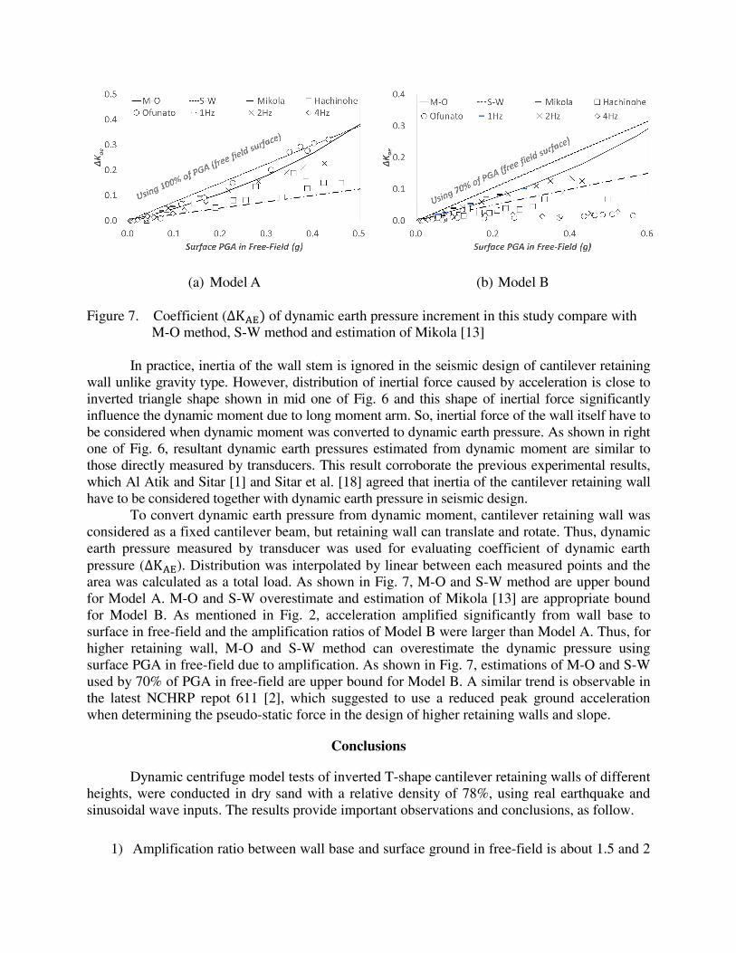
Figure 7. Coefficient (∆K of dynamic earth pressure increment in this study compare with
M-O method, S-W method and estimation of Mikola [13] In practice, inertia of the wall stem is ignored in the seismic design of cantilever retaining
wall unlike gravity type. However, distribution of inertial force caused by acceleration is close to inverted triangle shape shown in mid one of Fig. 6 and this shape of inertial force significantly influence the dynamic moment due to long moment arm. So, inertial force of the wall itself have to be considered when dynamic moment was converted to dynamic earth pressure. As shown in right one of Fig. 6, resultant dynamic earth pressures estimated from dynamic moment are similar to those directly measured by transducers. This result corroborate the previous experimental results, which Al Atik and Sitar [1] and Sitar et al. [18] agreed that inertia of the cantilever retaining wall have to be considered together with dynamic earth pressure in seismic design.
To convert dynamic earth pressure from dynamic moment, cantilever retaining wall was considered as a fixed cantilever beam, but retaining wall can translate and rotate. Thus, dynamic earth pressure measured by transducer was used for evaluating coefficient of dynamic earth pressure (∆K ). Distribution was interpolated by linear between each measured points and the area was calculated as a total load. As shown in Fig. 7, M-O and S-W method are upper bound for Model A. M-O and S-W overestimate and estimation of Mikola [13] are appropriate bound for Model B. As mentioned in Fig. 2, acceleration amplified significantly from wall base to surface in free-field and the amplification ratios of Model B were larger than Model A. Thus, for higher retaining wall, M-O and S-W method can overestimate the dynamic pressure using surface PGA in free-field due to amplification. As shown in Fig. 7, estimations of M-O and S-W used by 70% of PGA in free-field are upper bound for Model B. A similar trend is observable in the latest NCHRP repot 611 [2], which suggested to use a reduced peak ground acceleration when determining the pseudo-static force in the design of higher retaining walls and slope.
Conclusions
Dynamic centrifuge model tests of inverted T-shape cantilever retaining walls of different heights, were conducted in dry sand with a relative density of 78%, using real earthquake and sinusoidal wave inputs. The results provide important observations and conclusions, as follow.
1) Amplification ratio between wall base and surface ground in free-field is about 1.5 and 2

for Model A and Model B, respectively. Thus, for higher retaining wall, amplification of acceleration have to be considered to use M-O and S-W method. And maximum dynamic moment did not occur simultaneously with dynamic earth pressure for Model B. This makes difference from hypothesis of M-O method and reduced the dynamic earth pressure.
2) Distribution of dynamic earth pressure tend to be a triangular shape and its resultant
loading point is close to one third of wall height. Dynamic loading point (0.6H) of S-W method is too high for dynamic moment and significantly overestimated dynamic bending moments.
3) Coefficient of dynamic earth pressure was back-calculated regardless of dynamic thrust point. Estimations of M-O and S-W method are upper bound for Model A and using 70% of PGA is more reliable and effective for higher retaining wall such as Model B.
Acknowledgments
The experiments are carried out in KOCED Geo-Centrifuge Facility using KREONET.
This research was supported by a grant (11 Technology Innovation D02) from Construction Technology Innovation Program funded by Ministry of Land, Infrastructure and Transport of Korean government.
References 1. Al Atik L, Sitar N. Seismic Earth Pressures on Cantilever Retaining Structures. Journal of Geotechnical and
Geoenvironmental Engineering 2010; 136 (10): 1324-1333.
2. Anderson DG. Seismic Design and Analysis of Retaining Walls, Buried Structures, Slopes and Embankments. NCHRP Report 611: Transportation Research Board, National Cooperative Highway Research Program, Washington, D.C, 2008.
3. Chopra AK. Dynamics of structures. Pearson Prentice Hall: New Jersey, 2007.
4. Council, B. S. S. NEHRP Recommended Provisions for Seismic Regulations for New Buildings and Other Structures (FEMA 750), 2009 Edition, Part 1 – Provisions: BSSC, Washington, DC, 2010.
5. Gazetas G, Psarropoulos PN, Anastasopouos I, Gerolymos N. Seismic behaviour of flexible retaining systems subjected to short-duration moderately strong excitation. Soil Dynamics and Earthquake Engineering 2004; 24(7): 537-550.
6. Green RA, Olgun CG, Cameron WI. Response and Modeling of Cantilever Retaining Walls Subjected to Seismic Motions. Computer-Aided Civil and Infrastructure Engineering 2008; 23:309-322
7. Jo SB, Ha JG, Choo YW, Kim DS. Seismic Behavior of Flexible Inverted T-Shape Retaining Wall via Dynamic Centrifuge Testing, Proceedings of the 18th Southeast Asian Geotechnical Conference cum Inaugural AGSSEA Conference 2013.
8. Kim DS, Kim NR, Choo YW, Cho GC. A newly developed state-of-the-art geotechnical centrifuge in Korea. KSCE Journal of Civil Engineering 2013; 17(1): 77-84.
9. Kim DS, Lee SH, Choo YW, Perdriat J. Self-balanced earthquake simulator on centrifuge and dynamic performance verification. KSCE Journal of Civil Engineering 2013; 17(4): 651-661.
10. Kim NR, Kim DS. A Shear Wave Velocity Tomography System for Geotechnical Centrifuge Testing. Geotechnical Testing Journal 2010; 33(6): 1-11.

11. Lee SH, Choo YW, Kim DS. Performance of an equivalent shear beam (ESB) model container for dynamic geotechnical centrifuge tests. Soil Dynamics and Earthquake Engineering 2013; 44: 102-114.
12. Lew M, Simantob E, Hudson ME. Performance of shored earth retaining systems during the January 17, 1994, Northridge earthquake. Proceeding 3rd International Conference on Recent Advances in Geotechnical Earthquake Engineering and Soil Dynamics 1995; 3.
13. Mikola RG. Seismic Earth Pressures on Retaining Structures and Basement Walls in Cohesionless Soils. Engineering - Civil and Environmental Engineering, University of California: Berkeley, Doctor of Philosophy, 2012.
14. Mononobe N, Matsuo H. On the determination of earth pressures during earthquakes. Proceedings of the World Engineering Congress, Tokyo.
15. Nakamura S. Reexamination of mononobe-okabe theory of gravity retaining walls using centrifuge model tests. Soils and Foundations 2006 46 (2): 135-146.
16. Okabe S. General theory of earth pressures. Journal of Japan Society of Civil Engineers 1926; 12 (1).
17. Seed HB, Whitman RV. Design of earth retaining structures for dynamic loads. Proceeding of ASCE Specialty Conference on Lateral Stresses in the Ground and Design of Earth Retaining Structures, Cornell Univ., Ithaca, New York; 1970.
18. Sitar N, Mikola R, Candia G. Seismically Induced Lateral Earth Pressures on Retaining Structures and Basement Walls, Geotechnical Engineering State of the Art and Practice: Keynote Lectures from GeoCongress 2012; 335-358.