Embed Size (px)
Citation preview
DIGEST D4JUNE 1995E
TE
RC
NO
CD
EC
RO
FN
IE
R
Sun Alliance Tower,Chatswood, NSW
STEELREINFORCEMENTINSTITUTE OFAUSTRALIA
BetterBuilt withConcrete
Alice Springs
200
4000
20
40
Darwin
Canbe
Melbourne
Adelaide
A R A F U R A S E A
G R E A T A U S T R A L I A N B I G H T
S O U T H E R N O C E A N
T I M O RS E A
G U L F O F
C A R P E N T A R I A
Seismic Detailing for Reinforced ConcreteBuildings in Australia
2
ForewordContents
I AM PLEASED to introduce this new publication on behalf ofthe Steel Reinforcement Institute of Australia. As a practicingdesign engineer with over 25 years general design experienceand 12 years seismic design experience, the importance of correctdetailing cannot be overemphasised in earthquake design.
Earthquake engineering, as we know it today, is at besta very imprecise art and much of our knowledge comes from theperformance of buildings under actual earthquake loads. Thishas repeatedly shown that properly detailed buildings withconfinement reinforcement perform far better than normallyreinforced buildings detailed only for vertical loads.
Of all of the design considerations the designer mustallow for in earthquake design, detailing and connection are byfar the most important as an earthquake will always expose theweakest link in the structure when it strikes.
I welcome and commend this publication to you.
John Woodside
Principal Connell Wagner Pty Ltd and Chairman BD6/4 responsible for the preparation of AS 1170.4 on behalf of Standards Australia.
3 Introduction
3 Seismicity in Australia
5 Reinforced Concrete and Earthquakes
5 Australian Standards Requirements
7 Design Methodology
8 Detailing of Structural Elements for Earthquake Resistance
8 Shear Walls and Braced Frames
8 Building Frame Systems
10 Reinforced Braced Frames
10 Moment Resisting Frame Systems
11 Intermediate Moment Resisting Frames
19 Precast Concrete
20 Tilt-Up
21 Foundation Systems
22 ConclusionsThe SRIA would like to thank the followingpeople and organisations for their assistance inthe writing of this publication:
John Woodside Principal, Connell Wagner, andChairman of Standards Australia Committee BD 6/4Earthquake Loading, for kindly providing the Forewordand giving constructive criticism on the draft document.
Des Bull Cement and Concrete Association Fellow,University of Canterbury, New Zealand, for invaluablehelp in providing information regarding capacity designand detailing, precast construction, and providingconstructive criticism on the draft document.
Paul Sancandi Director, Meinhardt (NSW) Pty Ltd andMark Zvirblis, Public Relations Manager, of ConcreteConstructions Group Pty Ltd for the articles andillustrations on the Sun Alliance Headquarters.
Harold Isaacs Standards Australia, for elaborating onthe historical development and rationale behind theearthquake provisions of AS 3600–1994.
Kevin McCue Australian Geological SurveyOrganisation, for advice on Australian seismicity andpermission to reproduce the seismic hazard map.
John Ward BHP Steel Rod and Bar Products Division,for information on reinforcement properties underseismic loading.
Concrete Reinforcing Steel Institute 933 NorthPlum Grove Road, Schaumburg, Illinois, USA, forinformation on US seismic practice and the photographsand project information on Burbank Tower and theNorthridge Hospital Medical Centre parking garage.
Acknowledgments
© Steel Reinforcement Institute of Australia 1995Except where the Copyright Act allows otherwise, nopart of this publication may be reproduced, stored in a retrieval system in any form or transmitted by anymeans without prior permission in writing of the Steel Reinforcement Institute of Australia.
First published 1995
Click subject to
go to it
Introduction
This publication discussesdetailing requirements of AS 3600Concrete Structures1 which wereamended in 1994 in response to therelease of the new AustralianEarthquake Loading Code AS 1170.42.Following a brief overview ofseismicity in Australia and relevantcode requirements, the discussionfocuses on reinforcement detailingaspects for building structures inregions of lower seismicity whereseismic forces are still likely to have asignificant impact on design. This isusually on structures from 5 to 15storeys, as for higher structures windloads will generally govern. Forbuildings lower than 5 storeys,
earthquake loads may not govern due to the designcategory; however, seismic design might be required if thebuilding is irregular. Wind and earthquake loadings arefundamentally different due to the cyclical nature of seismicaction, while although wind loads may govern, limiteddetailing for seismic load will still be required. In particular,this publication shows how the requirements of the newloading code can be met through the use of predominantlysimple 'seismic' details and by following general gooddetailing practice. Further, it will be seen how anappreciation of structural performance under seismicconditions will enable the structure to satisfactorilywithstand the anticipated earthquake loads. The ease of useof these details is illustrated by commentary fromConsulting Engineers and Builders involved in one ofAustralia’s most recent seismically designed buildingstructures. It is interesting to note that similar details havebeen used in Adelaide for reinforced concrete buildings over12 metres in height since 1982. Examples of relevantoverseas structures are also used to illustrate preferredconstruction practice. This publication is not intended to bea comprehensive design guide, and readers are referred to anumber of excellent texts currently available, especiallySeismic Design of Reinforced Concrete and MasonryBuildings3 and Concrete Structures in EarthquakeRegions: Design and Analysis4.
Seismicity in Australia
The Newcastle earthquake of 1989 was one ofAustralia’s most expensive natural disasters, costing upwardsof $1.5 billion, causing 13 deaths and 120 injuries. This tollwould have been much greater but for chance. The NewcastleWorkers Club for instance, which collapsed during theearthquake, regularly held major events at which hundredsof people would be present. At the time, research intoearthquake engineering was underway at academicinstitutions, and the Australian Standards Code Committeefor a new earthquake loading code to replace AS 2121 wasalready formed. However, the event threw into sharp reliefthe need for the building industry to place greater emphasison seismicity in the design and construction of our buildingstructures. The philosophy now implicit in the seismicdesign of building structures is to:
■ minimise loss of life, structural collapse and damage;and
■ improve post-disaster recovery.
Whilst the Newcastle earthquake was a majornatural disaster and the most expensive insurance loss inAustralian history, it should be placed into perspective.
Australia is the world’s sixth largest country (almost8 million square kilometres), but its population of approxi-mately 17 million is predominantly located in a coastal stripbetween Brisbane and Adelaide and concentrated inrelatively few major urban centres. Australian earthquakestend to be shallow, of short duration, and although theymay be felt over a great distance, have a relatively smallarea of influence in contrast with those experienced in NewZealand, Japan and California. These considerations result,therefore, in Australia being classified as a 'low-risk' but'high-consequence' area in terms of earthquake damage, iethe likelihood of an earthquake occurring in a major urbanarea is low but the consequences, should one occur, arelikely to be severe. Furthermore, on average, Australiaexperiences earthquakes of Richter magnitude 6 or greaterevery five years, ie with amplitudes of ground motion of 2.5times and released energy at least 4 times as great as thoseexperienced in the Newcastle earthquake which measuredmagnitude 5.6 on the Richter scale. However, in intraplateareas such as Australia, it is not possible to accuratelypredict the time, location and intensity of earthquakes.
Both AS 1170.4 and Appendix A of AS 3600 (whichare discussed below) are based on US experience modifiedfor Australian seismological conditions and buildingpractices. The requirements of these two codes allow for thepossible seismological forces which a building structuresituated in Australia may reasonably be expected to undergoat some point during its life.
Seismic Detailing for Reinforced ConcreteBuildings in Australia
Philip SandersNational Engineer, Steel Reinforcement Institute of Australia
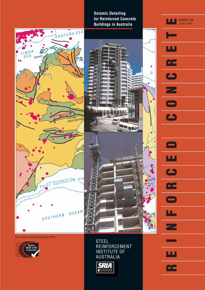
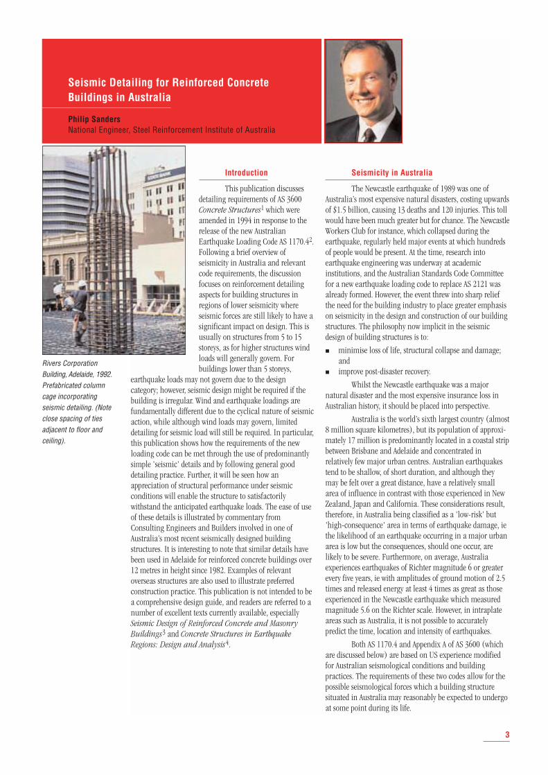
Rivers CorporationBuilding, Adelaide, 1992.Prefabricated columncage incorporatingseismic detailing. (Noteclose spacing of tiesadjacent to floor andceiling).
3
4
O C
E A
N
108 114 156
16
20
24
28
32
36
40
126 132 138 144 150
40
36
32
28
24
20
12
8
150 144 138 132 126 120
8
12
Bathymetric contour (m)
24/A/161
0 500 km
120
114
102
Alice Springs
44
Palaeozoic
Proterozoic
Mesozoic to Cainozoic
Late Proterozoic to Palaeozoic
Early to Mid Proterozoic
Fault
4.0-4.9 5.0-5.9 DEPTH (km)
0-40
PLATFORM COVERSOROGENIC DOMAINS
200
4000
200
4000
200
200
4000
4000
200
4000
44
I N D
I A
N
Archaean
Darwin
Perth
Brisbane
SydneyCanberra
Hobart
Melbourne
Adelaide
A R A F U R A S E A
G R E A T A U S T R A L I A N B I G H T
S O U T H E R N O C E A N
MAGNITUDES> 6.0
200
16
Simple Conic Projection with Standard Parallels 18 S and 36 S
T A S M A NS E A
S O
U T
H
P
A C
I F I
C
O C
E A
N
T I M O RS E A
G U L F O F C A R P E N T A R I A
C O R A LS E A
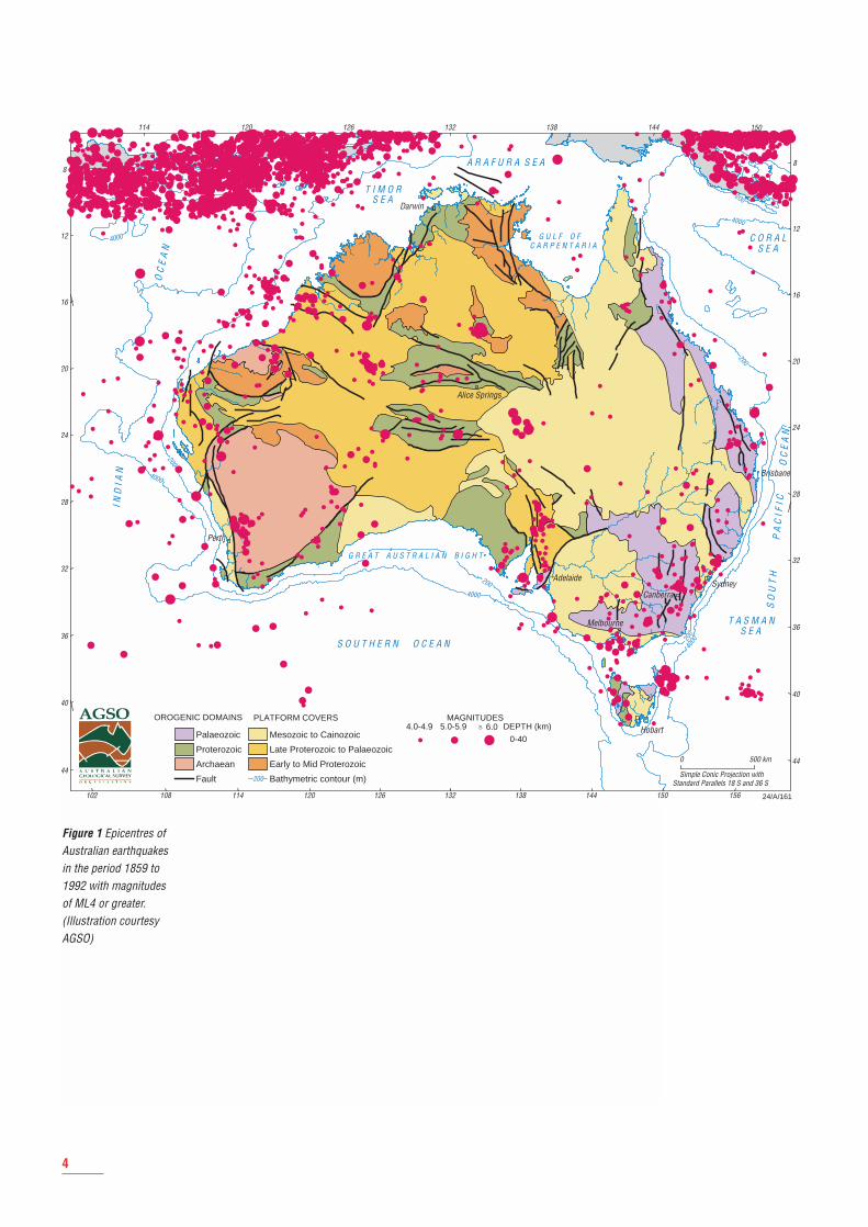
Figure 1 Epicentres ofAustralian earthquakesin the period 1859 to1992 with magnitudesof ML4 or greater.(Illustration courtesyAGSO)
Reinforced Concrete and Earthquakes
As discussed above, due to the relatively shorthistory of seismological measurement in Australia, it is notpossible to predict the response spectra, time or location of aseismic event with any degree of accuracy. Even overseas incountries more culturally adapted to earthquakes, surprisescan occur which cause major catastrophes.
The Kobe, or Great Hanshin, earthquake of 17 January1995 and the Northridge, Los Angeles, earthquake of 17 January 1994 were just two examples where this has beenthe case. Both of these events highlighted the strengths andweaknesses of reinforced concrete in terms of designmethodologies and as a structural material.
It is widely recognised that reinforced concrete doessuffer from a number of drawbacks when compared to steelor timber structures since concrete:
■ has an unfavourable mass to strength ratio;
■ exhibits brittle behaviour when failing in shear –particularly for low levels of shear reinforcement;
■ possesses a lack of ductility in compression wheninadequately confined.
The mass to strength ratio is important becauseearthquake loads arise from inertial effects, and so areproportional to mass. Clearly, concrete is at a distinctdisadvantage here compared to steel and timber. The brittlebehaviour exhibited in shear can be overcome by providinga sufficient reserve of strength to suppress such failures,while transverse confining steel greatly increases theductility of concrete in compression.
Reinforced concrete does, however, possess anumber of attributes which enable it to be successfullyemployed in structures resisting seismic loads:
■ Properly conceived and detailed concrete structurespossess excellent ductility in bending, which can equalthat of structural steel.
■ Well-confined concrete can possess good ductility underflexure and axial compression, with a lower tendencyfor buckling failure compared with an equivalent steelstructure.
■ Properly detailed concrete construction provides amonolithic structure, which contributes to good overallcontinuity, in itself a good earthquake-resistant feature.
■ Shear walls can be an economical means of providinghigh lateral strength and stiffness, while still retainingsignificant ductility. (Well-designed 'shear' walls do notfail in shear, despite their name.)
■ Internal damping before yielding is likely to be greaterthan in steel structures (approximately 6% comparedwith 3%). This is important for serviceabilityconsiderations during moderate earthquakes.
■ In many countries, concrete is the building material ofchoice; the technology is familiar and at least some ofthe materials are locally available and cheap, while thefinished structure can possess good sound and thermalinsulation properties.
It should be noted that despite the commonly heldview, modern steel structures are not immune from collapseor significant damage during seismic events (eg theAutomobile Club of Southern California built in 1992 anddemolished after the Northridge earthquake), while manywell-designed concrete structures have survived majorearthquakes undamaged as seen in Kobe and Northridge (see The California Experience below). There is a wealth ofexperimental and theoretical evidence to support thispotential for good seismic performance from structuralconcrete in readily available literature3,4.
Australian Standards Requirements
AS 1170.4 sets out a number of earthquake designcategories. These provide the particular degree of design anddetailing consideration required for the level of seismicityexpected. As structures will also be designed for wind forces,the relative effects of both must be considered for Australianconditions. Wind strength requirements may be more onerousthan those for earthquake loading. It should be noted,however, that even if this is the case, additional earthquakerequirements for detailing must still be considered due to:
■ the significant degree of crudeness by which earthquakeforces are determined;
■ the fact that even in columns designed to be elastic (ie with a Structural Response Factor of 1.0), if theearthquake is larger than expected and the concretecover spalls, the compression reinforcement will buckle,resulting in the loss of core confinement and sheartransfer mechanism (see below).
Appendix A forms a normative part of AS 3600. Itsets out additional minimum requirements for the designand detailing of reinforced concrete structures underearthquake actions, as defined in AS 1170.4. Many of theseprovisions are based on Californian practice as codified inACI 318-89 (amended 1992)5 and modified for Australianconditions. The Appendix sets out and defines theconstruction systems and categories in relation to theearthquake design categories considered in AS 1170.4.
The requirements of Appendix A are considered withparticular regard to structural systems set out in AS 1170.4, ie:
■ Bearing wall systems Structural systems with loadbearingwalls providing support for all or most of the verticalloads and shear walls or braced frames providing thehorizontal earthquake resistance
■ Building frame systems Structural systems in which anessentially complete space frame supports the verticalloads and shear walls or braced frames provide thehorizontal earthquake resistance
■ Moment resisting frame systems (MRFs) Structural systemsin which an essentially complete space frame supportsthe vertical loads and the total prescribed horizontalearthquake forces by the flexural action of members.
5
Three types of MRF are defined in the Code:
■ Ordinary Moment Resisting Frames (OMRF) Defined asmoment resisting frames not more than 50 m in overallheight above structural base, complying with therequirements of AS 3600, but not being required tosatisfy the additional detailing requirements ofAppendix A of AS 3600 or of 1170.4. The authorrecommends, however, that certain minimum seismicdetails be adopted to prevent the possibility of brittlefailure, with catastrophic consequences, should thedesign forces be exceeded by an unexpectedly largeseismic event (see below).
■ Intermediate Moment Resisting Frames (IMRF) Definedas moment resisting frames of ductile construction,complying with the requirements of AS 3600, togetherwith the additional requirements of Appendix A of AS 3600 and AS 1170.4.
■ Special Moment Resisting Frames (SMRF) Concrete spaceframes designed in accordance with AS 3600, in whichmembers and joints are capable of resisting forces byflexure as well as axial forces along the axis of themembers with special ductility requirements. Fewstructures that designers will come across will fallwithin this category in Australia.
Detailing requirements for the more onerous conditionsof Special Moment Resisting Frames (SMRF) are notcovered in Appendix A. Designers requiring guidance forthese conditions are referred to ACI 318-89(92).
■ Dual systems Structural systems in which an essentiallycomplete space frame provides support for the verticalloads and at least a quarter of the prescribed horizontalforces are resisted by a combination of the momentframe, shear walls or braced frames, in proportion totheir relative rigidities.
Once selected, it is imperative that the structuralsystem is designed and detailed to ensure that the systemwill behave in the way intended.
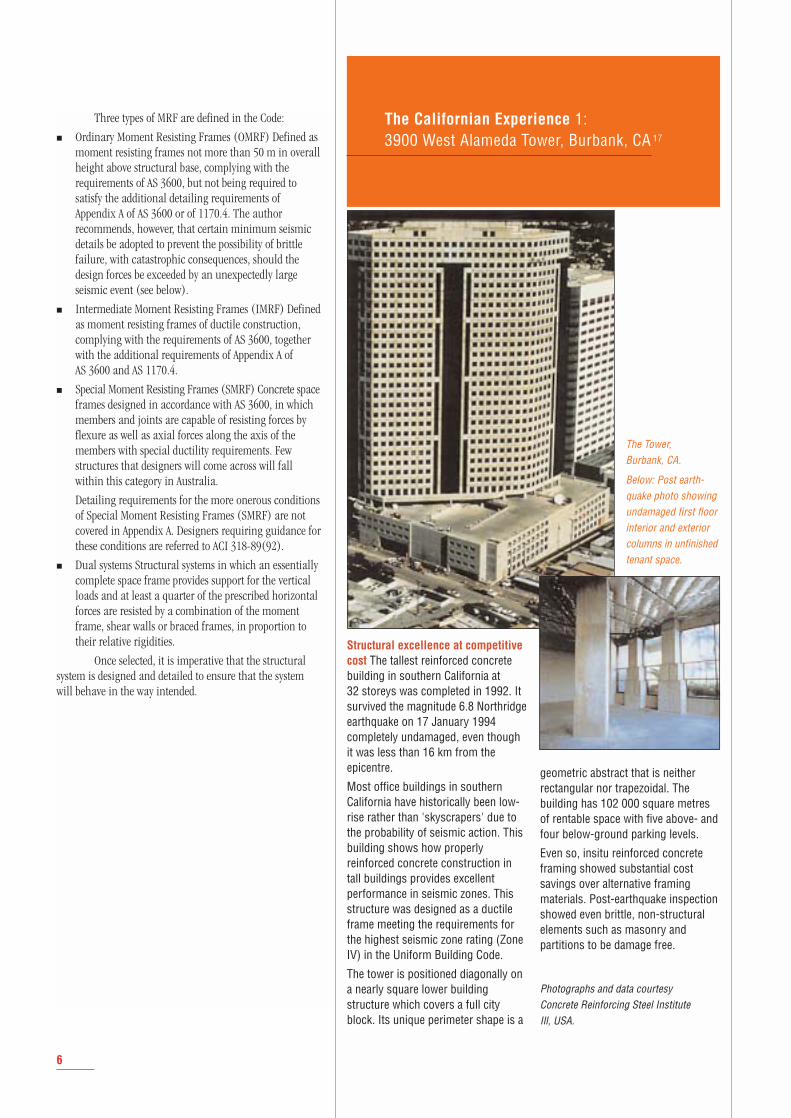
The Californian Experience 1:3900 West Alameda Tower, Burbank, CA 17
Structural excellence at competitivecost The tallest reinforced concretebuilding in southern California at 32 storeys was completed in 1992. Itsurvived the magnitude 6.8 Northridgeearthquake on 17 January 1994completely undamaged, even thoughit was less than 16 km from theepicentre.
Most office buildings in southernCalifornia have historically been low-rise rather than 'skyscrapers' due tothe probability of seismic action. Thisbuilding shows how properlyreinforced concrete construction intall buildings provides excellentperformance in seismic zones. Thisstructure was designed as a ductileframe meeting the requirements forthe highest seismic zone rating (ZoneIV) in the Uniform Building Code.
The tower is positioned diagonally ona nearly square lower buildingstructure which covers a full cityblock. Its unique perimeter shape is a
geometric abstract that is neitherrectangular nor trapezoidal. Thebuilding has 102 000 square metresof rentable space with five above- andfour below-ground parking levels.
Even so, insitu reinforced concreteframing showed substantial costsavings over alternative framingmaterials. Post-earthquake inspectionshowed even brittle, non-structuralelements such as masonry andpartitions to be damage free.
Photographs and data courtesy Concrete Reinforcing Steel Institute Ill, USA.
The Tower, Burbank, CA.
Below: Post earth-quake photo showingundamaged first floorinterior and exteriorcolumns in unfinishedtenant space.
6
Design Methodology
A chain is only as strong as its weakest link …
If one considers a chain comprising a number oflinks, each with equal strength and ductility, and subjects itto a tensile force, which link will break first?
The answer is that it is not possible to predict whichwill fail. The design structural engineer is in a similarpredicament regarding the seismic performance of a buildingstructure. The point of failure could be at any one of a numberof locations, affected not just by such considerations asdesign strength and stiffness, but also by such matters as theprovision, for fixing purposes, of a greater number of barsthan required, strain hardening of reinforcement duringcyclical action, and the overstrength of the reinforcementmaterial above its nominal yield strength.
Paulay3 uses this analogy to explain the concept of'Capacity Design' for building structures. Structural failureoccurs when the flexural strength of the member is exceededby the forces placed upon it, ie 'demand' exceeds 'capacity'.This capacity then is set at the 'ultimate limit state' or themaximum credible earthquake the structure may be expectedto undergo during its life. Below this, the structure would beexpected to survive without experiencing severe damage.
Capacity Design essentially involves the designerpicking the positions of failure in the structure and ensuringthat these failures are ductile and controlled in mannerrather than brittle and catastrophic. Further, by choosingthe location of the formation of these ductile failures or'plastic hinges', the designer ensures that failure does notoccur at critical points in the structure. Failure in the non-ductile elements can be prevented if their strength is inexcess of the maximum strength (including overstrength) ofthe ductile elements.
The formation of plastic hinges uses up energy.Once all plastic hinges have formed, the structure will beunable to take any additional seismic load – effectively actingas a 'fuse' to prevent overload and collapse.
Most multi-storey reinforced concrete buildingsconstructed in Australia will be in either Earthquake DesignCategories B or C, ie they will be over four storeys but below50 m in height, be founded on medium-density clays, sands,gravels or rock, and fall within Structure Classification Type IIas defined in AS 1170.4 (eg offices or residential buildings ofmore than four storeys, hotels and motels, most hospitalfacilities – excluding those essential for post-disaster recovery).
For Categories B and higher, AS 1170.4 specifiesthat all parts of a structure shall be interconnected, in boththe horizontal and vertical directions. The connections areto be capable of transmitting the calculated horizontalearthquake force (Fp) in order to provide load paths from allparts of the structure. This enables earthquake forces to becarried to the foundation.
For Categories C and higher, diaphragm action is tobe considered in the design in the same manner as wallanchorage to provide connection between the walls and theroof and floors. Openings in shear walls and diaphragmsrequire additional reinforcement at the edges and corners to
resist local stresses. Footings supported on piles, caissons, orspread footings, located in soils with a maximum ultimatebearing capacity of less than 250 kPa, must be restrained inthe horizontal direction to limit differential movementduring an earthquake.
The decision as to which design route to take is leftlargely to the engineer, eg Ordinary Moment Resisting Framesare deemed to require no further detailing considerationfrom those required in the body of AS 3600 (but see commentson minimum detailing requirements below). However, theStructural Response Factor, Rf, (a function of the ductilityprovided in the frame and an 'overstrength' factor), may beincreased by 50% if the designer opts for an IntermediateMoment Resisting Frame, thus considerably reducing thehorizontal earthquake base shear force. The extra designand detailing required for an IMRF may well proveeconomical by permitting reduced member sizes.
Another point to note is that excess strength providedabove that notionally required by the design – for instancedue to the provision of additional reinforcement for tying, orextra thickness or depth of section for fire requirements –means less ductility is required for the element. Therefore,less detailing for seismic resistance is required and theremay be a resulting increase in buildability. Tilt-up andloadbearing precast panels often fall into this category, forexample.
Drift It should be noted that even if a structure orpart of a structure is not designed specifically to withstandseismic forces, frames must be designed for the full drift(deflection) of the whole structure (eg in dual system orwith combined insitu/precast construction). ACI 318-92stipulates that a frame must be designed for twice thedeflection of the building as a whole. This is regarded as tooonerous for expected conditions in Australia. Instead, it isconsidered sufficient for the designer to allow for the gravity-supporting elements or frames to deflect to the maximumcalculated for the most ductile frame or element, ie theearthquake-resisting frame or shear wall, without failure.
Pounding Pounding, or the impact of adjoiningbuildings due to differing amplitudes of motion, can be aserious problem and one not often considered by designers.This can be especially acute in large cities due to the closeproximity of numbers of tall buildings of differing periods ofoscillation. Analytical studies have not been validatedexperimentally and separation to avoid pounding has usuallybeen based on design equations. If the motion experiencedis higher than specified, significant damage can occur.
7
Detailing of Structural Elements forEarthquake Resistance
Detailing of the structure is an integral and importantpart of the seismic design process. For reinforced concrete,structural detailing centres around arrangement of thereinforcing bars. There must be sufficient transverse steel tosuppress brittle shear or crushing failures and to preventbuckling of the main compression steel, once the coverconcrete has been lost. The main steel bars must not losetheir anchorage into the surrounding concrete during therepeated reversing loading cycles to which they would besubjected during a major earthquake.
Appendix A of AS 3600 sets out detailing criteria forgeneral, regular and irregular structures, as defined in AS 1170.4. Regular structures in Design Categories A and Bdo not need to be specifically designed or detailed forresistance to earthquake loads. For irregular structures inDesign Category B and structures in Design Categories C toE, the design action effects determined in AS 1170.4 aredependent upon both the type of structural system adoptedand the type of member being considered. The relevant levelof ductility is to be met by following the detailingrequirements for the particular structural system concerned.
It should perhaps be restated here that design anddetailing are inseparable. Proper detailing is required toensure that the structure will respond under seismic loadingin the manner for which it has been designed.
Shear Walls or Braced Frames
As AS 1170.4 assigns a low structural responsefactor (Rf) to reinforced or prestressed concrete shear wallsor braced frames in a bearing wall system, these elementsattract higher earthquake design forces. They are thereforerequired to be comparatively heavily reinforced and often willhave a reasonable excess of strength above that notionallyrequired. Appendix A allows elements in these systems to bedesigned and detailed in accordance with the main body ofthe code without further consideration. It must be noted by thedesigner, however, that the use of any Rf of greater than 1.0results in a design earthquake force of less than theanticipated actual loading. Reinforcement will then yieldonce the design earthquake force is reached and plastichinges form. Detailing must be provided to reflect this.
Building Frame Systems
As building frame systems are generally more ductilethan bearing wall systems, they are assigned a correspondinglyhigher Rf value in AS 1170.4. The earthquake design forcesare therefore lower. This may in turn result in less longitudinaland shear reinforcement. To maintain the required level ofductility, however, additional detailing is necessary.
The ductility provision requirements are as follows:
■ The reinforcement ratio, Pw ≥ 0.0025 both horizontallyand vertically (ie an increase from 0.0015 in the verticaldirection over cl 11.6.1).
■ The reinforcement is to be divided between the two faces, if:
tw > 200 mm; or φVu > (Ag.f'c)/6
where
tw = thickness of the wall
φVu = design shear strength
Ag = gross cross-sectional area
f'c = characteristic 28-day compressive cylinderstrength of concrete.
All reinforcement terminating in footings, columns,slabs and beams must be anchored to develop yield stress atthe junction of the wall and terminating member.
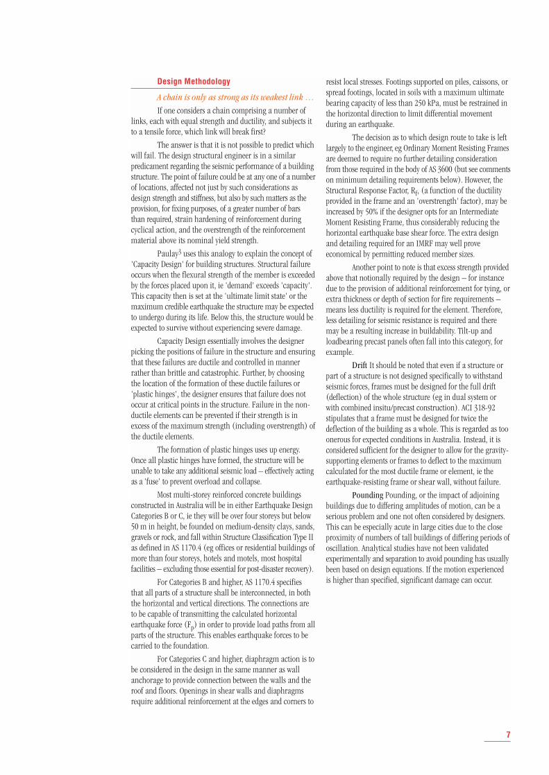
■ Boundary elements must be provided at discontinuousedges of shear walls and around openings where:
- vertical reinforcement is not restrained; and
- the extreme fibre compressive stress in the wall exceeds 0.15 f'c.
Note: This stress may not be the actual stressdeveloped, but is the 'trigger value' for determiningwhen a boundary element is required.
Restraint of the longitudinal reinforcement inboundary elements is to comply with Clause 10.7.3 or, if theextreme fibre compressive strength exceeds 0.2 f'c, with therequirements for Reinforced Braced Frames.
It should be noted that the above requirements donot necessarily result in an increase in wall thickness for aboundary element, only that the areas concerned aredesigned and detailed to resist specified axial forces Figure 2.
8
Special vertical boundary element
Anchorage to develop fsy at this point
db = diameter of bar
6db
Column (reinforcement not shown)
Anchorage to develop fsy at this point
Figure 2
Typical boundary element details (from AS 36002)
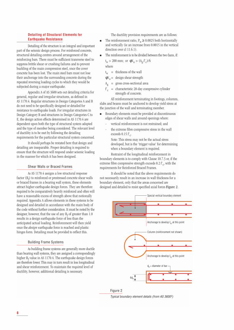
The Northridge Medical CentreParking Garage was completed in1989. Located at the epicentre of theNorthridge earthquake it came throughwithout damage. It is one of over 40such parking structures built by onecontractor, Sy Art, in the immediatevicinity of the earthquake – all ofwhich were undamaged.
This record is all the more remarkableas a number of other parkingstructures fared particularly badly.There were a number of causes ofthese failures. Predominantly thesewere weaknesses in design philosophy.Such issues as a lack or irregularsiting of stiffening elements, large wallopenings and inadequate attention todetailing, especially where changes ofconstruction type occurred.
Parking structure on California StateUniversity Northridge CampusA testament to ductile reinforcedconcrete? Collapse occurred due to thefailure of the internal precast concreteframe. The exterior elements – theprimary seismic resisting system –were constructed as an insitu ductileframe. A telling testament to the abilityof properly detailed reinforced concreteto perform in a ductile fashion.
(Photo courtesy EERC/University of California)
Different structural systems must becompatible Structural collapseoccurred due to a lack of driftcompatibility between the primaryseismic resisting system and theprecast gravity resisting structure.Seating of precast units must allowfor frame growth under lateraldeflection (see Figure 11).
(Photo courtesy CSIRO)
The Californian Experience 2:Parking Structures
Top and above:Exteriors of theNorthridge MedicalCentre Parking Garage.
Interior: Postearthquake photoshowing undamagedinterior columns,beam and slab.
(Photos courtesy CRSI)
9
Reinforced Braced Frames
Bracing members of braced frames are to bedesigned as struts or ties, as they will be subject to alternatingcompression and tension, and connections between membersare to have greater strength than each connected member.
In terms of detailing, it is important to provideadequate lateral restraint along the whole length of thelongitudinal reinforcement when it is subject to compressionin the form of:
■ helices: the volume of steel divided by the volume ofconcrete, per unit length of member must be greaterthan 0.12(f'c/fsy.f); or
■ closed ties:
Asv ≥ 0.30 sy1, (Ag/Ac-1) (f'c/fsy.f) (unless φNuo > N*)or or ≥ 0.09 sy1, (f'c/fsy.f); whichever is greater.
where
s = centre to centre spacing of the ties
y1 = the larger core dimension
Ag = the gross cross-sectional area of the column
Ac = the cross-sectional area of the core measuredover the outside of the ties
f'c = the characteristic compressive cylinder strengthof concrete at 28 days
fsy.f = the yield strength of the ties
φ = a strength reduction factor
Nuo = the ultimate strength in compression of anaxially loaded cross-section without eccentricity
N* = the axial compressive or tensile force on a cross-section.
Moment Resisting Frame Systems
As discussed above, there are three types of momentresisting frames:
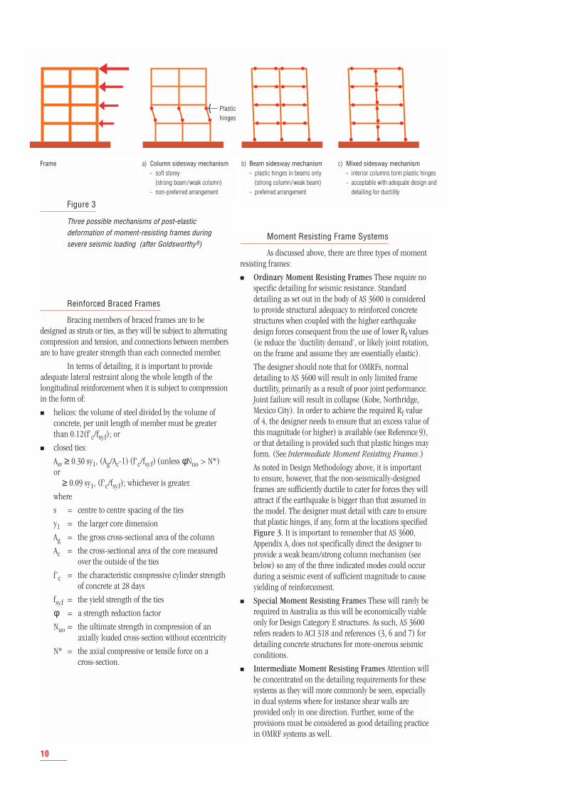
■ Ordinary Moment Resisting Frames These require nospecific detailing for seismic resistance. Standarddetailing as set out in the body of AS 3600 is consideredto provide structural adequacy to reinforced concretestructures when coupled with the higher earthquakedesign forces consequent from the use of lower Rf values(ie reduce the 'ductility demand', or likely joint rotation,on the frame and assume they are essentially elastic).
The designer should note that for OMRFs, normaldetailing to AS 3600 will result in only limited frameductility, primarily as a result of poor joint performance.Joint failure will result in collapse (Kobe, Northridge,Mexico City). In order to achieve the required Rf valueof 4, the designer needs to ensure that an excess value ofthis magnitude (or higher) is available (see Reference 9),or that detailing is provided such that plastic hinges mayform. (See Intermediate Moment Resisting Frames.)
As noted in Design Methodology above, it is importantto ensure, however, that the non-seismically-designedframes are sufficiently ductile to cater for forces they willattract if the earthquake is bigger than that assumed inthe model. The designer must detail with care to ensurethat plastic hinges, if any, form at the locations specifiedFigure 3. It is important to remember that AS 3600,Appendix A, does not specifically direct the designer toprovide a weak beam/strong column mechanism (seebelow) so any of the three indicated modes could occurduring a seismic event of sufficient magnitude to causeyielding of reinforcement.
■ Special Moment Resisting Frames These will rarely berequired in Australia as this will be economically viableonly for Design Category E structures. As such, AS 3600refers readers to ACI 318 and references (3, 6 and 7) fordetailing concrete structures for more-onerous seismicconditions.
■ Intermediate Moment Resisting Frames Attention willbe concentrated on the detailing requirements for thesesystems as they will more commonly be seen, especiallyin dual systems where for instance shear walls areprovided only in one direction. Further, some of theprovisions must be considered as good detailing practicein OMRF systems as well.
10
Plastichinges
Frame b) Beam sidesway mechanism- plastic hinges in beams only
(strong column/weak beam)- preferred arrangement
c) Mixed sidesway mechanism- interior columns form plastic hinges- acceptable with adequate design and
detailing for ductility
Figure 3
Three possible mechanisms of post-elasticdeformation of moment-resisting frames duringsevere seismic loading (after Goldsworthy9)
a) Column sidesway mechanism- soft storey
(strong beam/weak column)- non-preferred arrangement
Detailing Requirements for IntermediateMoment Resisting Frames
Beams Under the effects of earthquake action,flexural members are subjected to a number of reversals ofbending moment. To ensure adequate ductility potential inIMRFs, beams are always doubly, and continuously,reinforced Figure 4.
If yield occurs, the Young's Modulus of thereinforcement will not remain within the elastic part of thestress-strain curve, and that Bauschinger softening will occurunder cyclic loading. (The 'Bauschinger effect' is the changein the stress-strain relationship that occurs when a reinforc-ing bar is yielded in tension or compression and the directionof the stress is reversed. The distinct yield point is lost andthe stress-strain relationship takes on a curvilinear form.)The stable hysteretic response of the potential plastic hingeregion can be diminished through the 'pinching' of thehysteretic loop due to the influences of shear degradation ofthe region. This could be as a result of inadequate transversereinforcement or poor construction joints, for instance.
The effect of reversing moments is generallyconcentrated at the junctions between beam and column.The Appendix therefore, stipulates that in a span:
■ the positive moment strength at a support face is to benot less than one-third of the negative moment strengthprovided at the face of the support; and
■ neither the negative nor the positive moment strengthat any section along the member length is to be lessthan one-fifth of the maximum moment strengthprovided at the face of the support.
All longitudinal reinforcement must be anchoredbeyond the support face, so that at the face the full yieldstrength of the bars can be developed. This requires that:
■ longitudinal reinforcement is continuous throughintermediate supports, and
■ longitudinal reinforcement extends to the far face of theconfined region and is fully anchored.
Lapped splices in longitudinal reinforcement,located in a region of tension or reversing stress, are to beconfined by a minimum of two closed ties at each splice toinhibit the possibility of non-ductile failure at this point. Theposition of maximum moment under seismic load will bedependent upon the magnitude of the earthquake Figure 5.The position of the splice should therefore be located at aposition of known moment, perhaps in the middle third ofthe span, unless the designer is confident that the splice issufficiently confined to safely locate it elsewhere in the span.
11
D
Col.core
Closed ties
L1
S1
Ties
S2
Closed ties
S1
Closed ties50max
50max S1
L1 L1 Splice*
Splice*
Ln
do
do
Ln
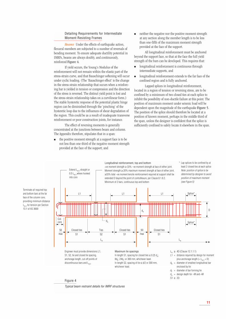
Figure 4
Typical beam restraint details for IMRF structures
Extend Lsy.t straight or0.5 Lsy.t where hookedinto core
Terminate all required topand bottom bars at the farface of the column core,providing minimum distanceLsy.t for tension per Section13.1 of AS 3600
* Lap splices to be confined by atleast 2 closed ties at each spliceNote: position of splice to bedetermined by designer to avoidposition of maximum moment (see Figure 5)
Engineer must provide dimensions L1,S1, S2, tie and closed tie spacing,anchorage length, cut-off points ofdiscontinuous bars and Lsy.t
Maximum tie spacings In length S1, spacing for closed ties ≤ 0.25 do;8db ; 24df ; or 300 mm, whichever least.In length S2, spacing of tie ≤ d/2 or 300 mm,whichever least.
Ln ≥ 4D (Clause 12.1.1.1)L1 = distance required by design for moment
plus anchorage length (= Lsy.t + D) db = diameter of smallest longitudinal bar
enclosed by tiedf = diameter of bar forming tiedo = design depth for –M and +MS1 ≥ 2D
Longitudinal reinforcement, top and bottom+ve moment strength ≥ 33% –ve moment strength at face of either joint. Moment strength ≥ 20% maximum moment strength at face of either joint. ≥33% total –ve moment tensile reinforcement required at support shall beextended D beyond the point of contraflexure, per Clause 8.1.8.2. Minimum of 2 bars, continuous top and bottom
Shear type failures tend to be brittle. Also, asmentioned above, maintaining a stable hysteretic responseof plastic hinge regions requires that the compression barsbe prevented from buckling. It must therefore be assumedthat major spalling of concrete cover will occur and that thecompression bars must rely solely upon transverse supportprovided by the ties. Limitations on maximum tie spacingare required to ensure that the effective buckling length ofthe compression bars is not excessive and that concretewithin the stirrup ties has reasonable confinement. Further-more, due to the possible occurrence of the Bauschingereffect and the reduced tangent modulus of elasticity of thesteel, a smaller effective length must be considered for barssubject to flexural compression, rather than compressionalone. The appendix specifies a minimum area of shearreinforcement:
Asv ≥ 0.5 bws/fsy.f (ie 50% greater than stipulated in thebody of the Code) with closed ties provided over aminimum distance of 2D from the face of the support.The first placed 50 mm from the support face, and theremainder spaced at 0.25 do, 8db, 24 df or 300 mm,whichever is least,
where:
bw = width of web.
s = centre to centre spacing of ties.
fsy.f = yield strength of ties.
D = overall depth of cross-section in the plane ofbending.
do = the distance from the extreme compression fibreof the concrete to the centroid of the outermostlayer of tensile reinforcement, but not less that0.8D.
db = the diameter of the smallest longitudinal barenclosed by the tie, and
df = the diameter of the bar forming the tie.
Since tension in vertical tie legs acts simultaneouslyto restrict longitudinal bar buckling and to transfer shearforce across diagonal cracks, it is considered that the tieareas are sufficient to satisfy both the requirements for barbuckling and those for shear resistance Figure 4.
(Note: these requirements do not preclude efficientfabrication techniques such as loose bar detailing asrecommended in the CIA detailing manual (8).)
Columns As discussed in Moment Resisting FrameSystems above, it is desirable to ensure that any plastic hingesthat may form should do so in the beam elements ratherthan the columns by ensuring that the flexural capacity ofthe column is higher than that of the beam by a significantmargin to allow for any 'overstrength' due to design ormaterials (see Design Methodology above.) This is known asthe 'weak beam/strong column' philosophy. Although itmay not always be possible to achieve this, especially withsuch forms of construction as band beams (see below), careshould be taken that catastrophic collapse, especially due tobrittle shear failure in the column will not occur.
In many cases, the ultimate compression strain ofunconfined concrete is inadequate to allow the structure toachieve the design level of ductility without excessive spallingof cover concrete. Adequate transverse reinforcement musttherefore be provided to confine the compressed concretewithin the core region to maintain its axial-load-carryingcapacity and to prevent buckling of the longitudinalcompression reinforcement and subsequent failure. Plastichinge regions are particularly susceptible where substantialaxial forces are present, eg in columns where inelasticdeformations must occur to develop a full hinge mechanism.(Note: this may occur even where the design is based uponweak beam/strong column philosophy, such as at the base ofall columns Figure 3b and c.)
Confinement Close-spaced transverse reinforce-ment acting in conjunction with longitudinal reinforcementrestrains the lateral expansion of the concrete. This enablesthe concrete to withstand higher levels of compression.Circular or helical ties, due to their shape, are placed in hooptension by the expanding concrete and provide confinementto the enclosed concrete Figure 6a. Rectangular ties applyfull confinement only near their corners as the pressure ofthe concrete bends the legs outwards. This tendency shouldbe counteracted by the use of cross-ties or interconnected
12
S1
CA B
S1
––
++
LAB
MC
MB
M'B
MA
M'A
LAC
h
Flexural capacityprovided
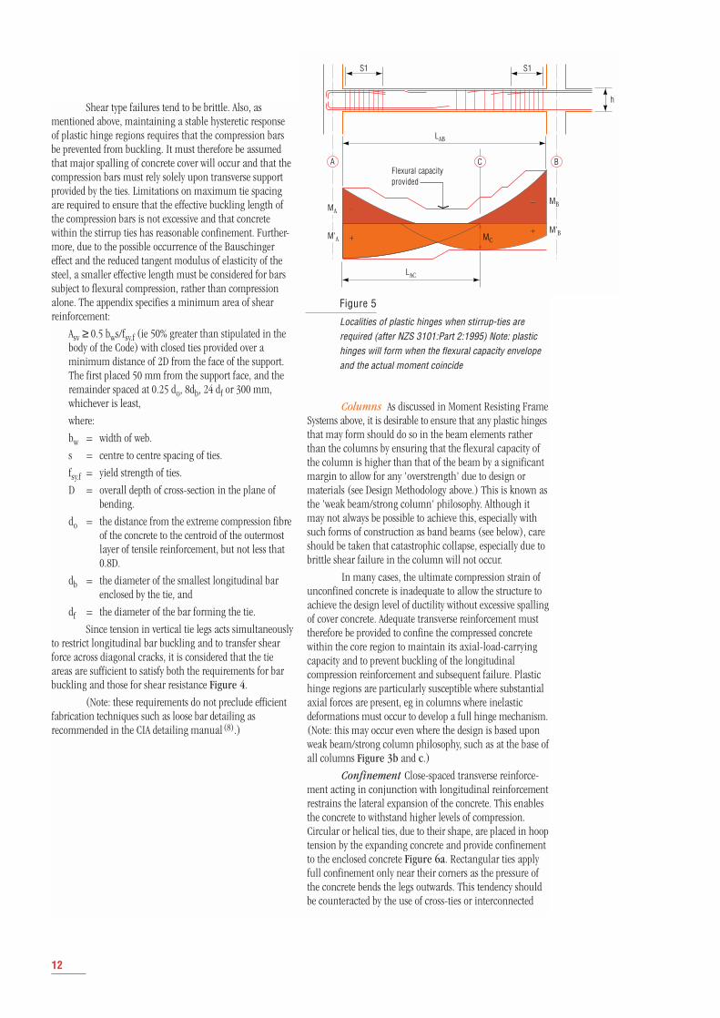
Figure 5
Localities of plastic hinges when stirrup-ties arerequired (after NZS 3101:Part 2:1995) Note: plastichinges will form when the flexural capacity envelopeand the actual moment coincide
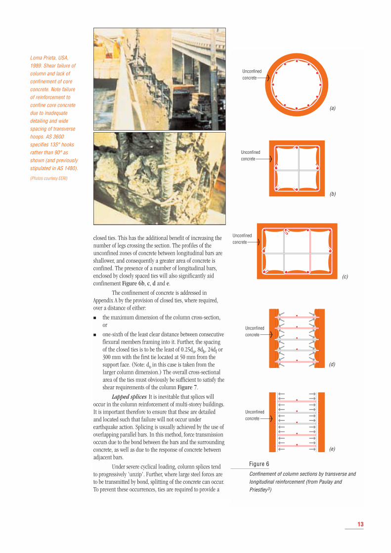
closed ties. This has the additional benefit of increasing thenumber of legs crossing the section. The profiles of theunconfined zones of concrete between longitudinal bars areshallower, and consequently a greater area of concrete isconfined. The presence of a number of longitudinal bars,enclosed by closely spaced ties will also significantly aidconfinement Figure 6b, c, d and e.
The confinement of concrete is addressed inAppendix A by the provision of closed ties, where required,over a distance of either:
■ the maximum dimension of the column cross-section,or
■ one-sixth of the least clear distance between consecutiveflexural members framing into it. Further, the spacingof the closed ties is to be the least of 0.25do, 8db, 24df or300 mm with the first tie located at 50 mm from thesupport face. (Note: do in this case is taken from thelarger column dimension.) The overall cross-sectionalarea of the ties must obviously be sufficient to satisfy theshear requirements of the column Figure 7.
Lapped splices It is inevitable that splices willoccur in the column reinforcement of multi-storey buildings.It is important therefore to ensure that these are detailedand located such that failure will not occur underearthquake action. Splicing is usually achieved by the use ofoverlapping parallel bars. In this method, force transmissionoccurs due to the bond between the bars and the surroundingconcrete, as well as due to the response of concrete betweenadjacent bars.
Under severe cyclical loading, column splices tendto progressively 'unzip'. Further, where large steel forces areto be transmitted by bond, splitting of the concrete can occur.To prevent these occurrences, ties are required to provide a
Loma Prieta, USA,1989. Shear failure ofcolumn and lack ofconfinement of coreconcrete. Note failureof reinforcement toconfine core concretedue to inadequatedetailing and widespacing of transversehoops. AS 3600specifies 135° hooksrather than 90° asshown (and previouslystipulated in AS 1480).
(Photos courtesy EERI)
13
Unconfinedconcrete
Unconfinedconcrete
Unconfinedconcrete
Unconfinedconcrete
Unconfinedconcrete
Figure 6
Confinement of column sections by transverse andlongitudinal reinforcement (from Paulay andPriestley3)
(e)
(d)
(c)
(b)
(a)
14
DClosedties
0.5 Sc
Sc
S
135°
0.5 Sc
Closedties
Clearcolumnheight
Fully scabble allconstruction joints
DClosedties
Columnties
df
ID = 4df
135°
df
Lo
ID = 4df
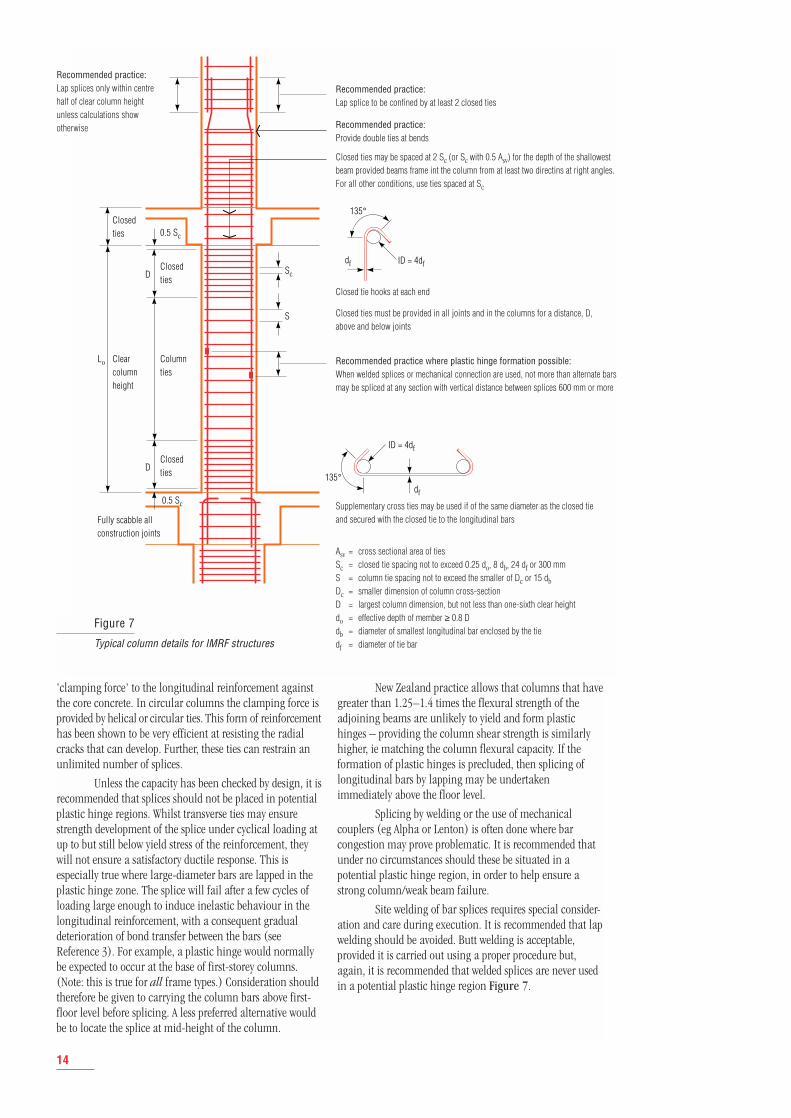
Figure 7
Typical column details for IMRF structures
Recommended practice:Lap splices only within centrehalf of clear column heightunless calculations showotherwise
Recommended practice:Lap splice to be confined by at least 2 closed ties
Recommended practice:Provide double ties at bends
Closed ties may be spaced at 2 Sc (or Sc with 0.5 Asv) for the depth of the shallowestbeam provided beams frame int the column from at least two directins at right angles.For all other conditions, use ties spaced at Sc
Closed tie hooks at each end
Closed ties must be provided in all joints and in the columns for a distance, D, above and below joints
Recommended practice where plastic hinge formation possible:When welded splices or mechanical connection are used, not more than alternate barsmay be spliced at any section with vertical distance between splices 600 mm or more
Supplementary cross ties may be used if of the same diameter as the closed tie and secured with the closed tie to the longitudinal bars
Asv = cross sectional area of tiesSc = closed tie spacing not to exceed 0.25 do, 8 db, 24 df or 300 mmS = column tie spacing not to exceed the smaller of Dc or 15 dbDc = smaller dimension of column cross-sectionD = largest column dimension, but not less than one-sixth clear heightdo = effective depth of member ≥ 0.8 Ddb = diameter of smallest longitudinal bar enclosed by the tiedf = diameter of tie bar
'clamping force' to the longitudinal reinforcement againstthe core concrete. In circular columns the clamping force isprovided by helical or circular ties. This form of reinforcementhas been shown to be very efficient at resisting the radialcracks that can develop. Further, these ties can restrain anunlimited number of splices.
Unless the capacity has been checked by design, it isrecommended that splices should not be placed in potentialplastic hinge regions. Whilst transverse ties may ensurestrength development of the splice under cyclical loading atup to but still below yield stress of the reinforcement, theywill not ensure a satisfactory ductile response. This isespecially true where large-diameter bars are lapped in theplastic hinge zone. The splice will fail after a few cycles ofloading large enough to induce inelastic behaviour in thelongitudinal reinforcement, with a consequent gradualdeterioration of bond transfer between the bars (seeReference 3). For example, a plastic hinge would normallybe expected to occur at the base of first-storey columns.(Note: this is true for all frame types.) Consideration shouldtherefore be given to carrying the column bars above first-floor level before splicing. A less preferred alternative wouldbe to locate the splice at mid-height of the column.
New Zealand practice allows that columns that havegreater than 1.25–1.4 times the flexural strength of theadjoining beams are unlikely to yield and form plastichinges – providing the column shear strength is similarlyhigher, ie matching the column flexural capacity. If theformation of plastic hinges is precluded, then splicing oflongitudinal bars by lapping may be undertakenimmediately above the floor level.
Splicing by welding or the use of mechanicalcouplers (eg Alpha or Lenton) is often done where barcongestion may prove problematic. It is recommended thatunder no circumstances should these be situated in apotential plastic hinge region, in order to help ensure astrong column/weak beam failure.
Site welding of bar splices requires special consider-ation and care during execution. It is recommended that lapwelding should be avoided. Butt welding is acceptable,provided it is carried out using a proper procedure but,again, it is recommended that welded splices are never usedin a potential plastic hinge region Figure 7.
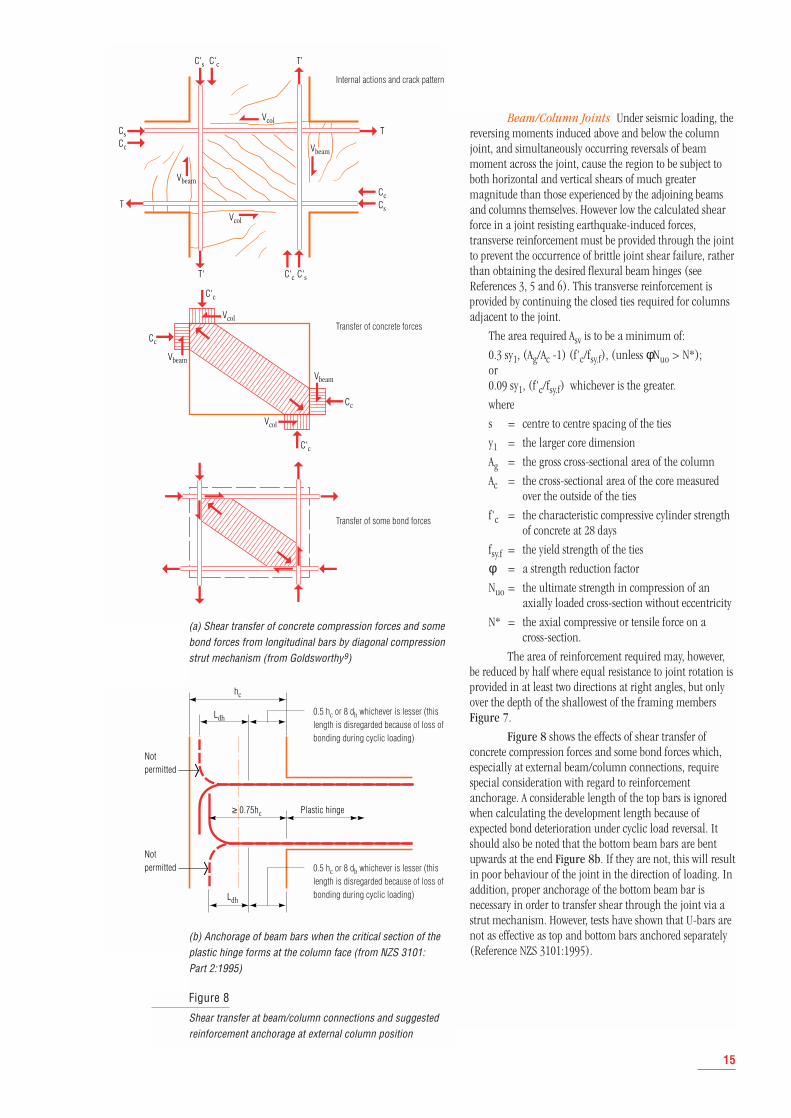
Beam/Column Joints Under seismic loading, thereversing moments induced above and below the columnjoint, and simultaneously occurring reversals of beammoment across the joint, cause the region to be subject toboth horizontal and vertical shears of much greatermagnitude than those experienced by the adjoining beamsand columns themselves. However low the calculated shearforce in a joint resisting earthquake-induced forces,transverse reinforcement must be provided through the jointto prevent the occurrence of brittle joint shear failure, ratherthan obtaining the desired flexural beam hinges (seeReferences 3, 5 and 6). This transverse reinforcement isprovided by continuing the closed ties required for columnsadjacent to the joint.
The area required Asv is to be a minimum of:
0.3 sy1, (Ag/Ac -1) (f'c/fsy.f), (unless φNuo > N*); or0.09 sy1, (f'c/fsy.f) whichever is the greater.
where
s = centre to centre spacing of the ties
y1 = the larger core dimension
Ag = the gross cross-sectional area of the column
Ac = the cross-sectional area of the core measuredover the outside of the ties
f'c = the characteristic compressive cylinder strengthof concrete at 28 days
fsy.f = the yield strength of the ties
φ = a strength reduction factor
Nuo = the ultimate strength in compression of anaxially loaded cross-section without eccentricity
N* = the axial compressive or tensile force on a cross-section.
The area of reinforcement required may, however,be reduced by half where equal resistance to joint rotation isprovided in at least two directions at right angles, but onlyover the depth of the shallowest of the framing membersFigure 7.
Figure 8 shows the effects of shear transfer ofconcrete compression forces and some bond forces which,especially at external beam/column connections, requirespecial consideration with regard to reinforcementanchorage. A considerable length of the top bars is ignoredwhen calculating the development length because ofexpected bond deterioration under cyclic load reversal. Itshould also be noted that the bottom beam bars are bentupwards at the end Figure 8b. If they are not, this will resultin poor behaviour of the joint in the direction of loading. Inaddition, proper anchorage of the bottom beam bar isnecessary in order to transfer shear through the joint via astrut mechanism. However, tests have shown that U-bars arenot as effective as top and bottom bars anchored separately(Reference NZS 3101:1995).
15
Cs
Vcol
Vbeam
Vbeam
Vcol
Cc
C's C'c T'
T' C'sC'c
T
Cs
CcT
Vcol
Vbeam
Vbeam
Vcol
Cc
C'c
C'c
Cc
Notpermitted
hc
≥ 0.75hc Plastic hinge
Ldh
Ldh
Notpermitted
Figure 8
Shear transfer at beam/column connections and suggestedreinforcement anchorage at external column position
Internal actions and crack pattern
Transfer of concrete forces
Transfer of some bond forces
(a) Shear transfer of concrete compression forces and somebond forces from longitudinal bars by diagonal compressionstrut mechanism (from Goldsworthy9)
0.5 hc or 8 db whichever is lesser (thislength is disregarded because of loss ofbonding during cyclic loading)
0.5 hc or 8 db whichever is lesser (thislength is disregarded because of loss ofbonding during cyclic loading)
(b) Anchorage of beam bars when the critical section of theplastic hinge forms at the column face (from NZS 3101:Part 2:1995)
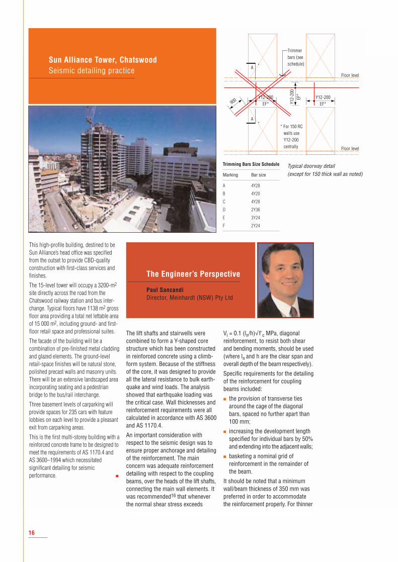
This high-profile building, destined to beSun Alliance’s head office was specifiedfrom the outset to provide CBD-qualityconstruction with first-class services andfinishes.
The 15-level tower will occupy a 3200-m2
site directly across the road from theChatswood railway station and bus inter-change. Typical floors have 1138 m2 grossfloor area providing a total net lettable areaof 15 000 m2, including ground- and first-floor retail space and professional suites.
The facade of the building will be acombination of pre-finished metal claddingand glazed elements. The ground-levelretail-space finishes will be natural stone,polished precast walls and masonry units.There will be an extensive landscaped areaincorporating seating and a pedestrianbridge to the bus/rail interchange.
Three basement levels of carparking willprovide spaces for 235 cars with featurelobbies on each level to provide a pleasantexit from carparking areas.
This is the first multi-storey building with areinforced concrete frame to be designed tomeet the requirements of AS 1170.4 andAS 3600–1994 which necessitatedsignificant detailing for seismicperformance. ■
Sun Alliance Tower, Chatswood Seismic detailing practice
16
The Engineer’s Perspective
Paul Sancandi Director, Meinhardt (NSW) Pty Ltd
Trimmerbars (seeschedule)
Floor level
Floor level
* For 150 RCwalls useY12-200centrally
Y12-200EF*Y1
2-20
0EF
*
Y12-200EF*900
A
A
Trimming Bars Size Schedule
Marking Bar size
A 4Y28
B 4Y20
C 4Y28
D 2Y36
E 3Y24
F 2Y24
The lift shafts and stairwells werecombined to form a Y-shaped corestructure which has been constructedin reinforced concrete using a climb-form system. Because of the stiffnessof the core, it was designed to provideall the lateral resistance to bulk earth-quake and wind loads. The analysisshowed that earthquake loading wasthe critical case. Wall thicknesses andreinforcement requirements were allcalculated in accordance with AS 3600and AS 1170.4.
An important consideration withrespect to the seismic design was toensure proper anchorage and detailingof the reinforcement. The mainconcern was adequate reinforcementdetailing with respect to the couplingbeams, over the heads of the lift shafts,connecting the main wall elements. Itwas recommended16 that wheneverthe normal shear stress exceeds
Vi = 0.1 (ln/h)√ f'c MPa, diagonalreinforcement, to resist both shearand bending moments, should be used(where ln and h are the clear span andoverall depth of the beam respectively).
Specific requirements for the detailingof the reinforcement for couplingbeams included:
■ the provision of transverse tiesaround the cage of the diagonalbars, spaced no further apart than100 mm;
■ increasing the development lengthspecified for individual bars by 50%and extending into the adjacentwalls;
■ basketing a nominal grid ofreinforcement in the remainder ofthe beam.
It should be noted that a minimumwall/beam thickness of 350 mm waspreferred in order to accommodatethe reinforcement properly. For thinner
Typical doorway detail (except for 150 thick wall as noted)
walls a single line of reinforcementmay be acceptable as long as thestresses in the compression 'strut'are within code limits.
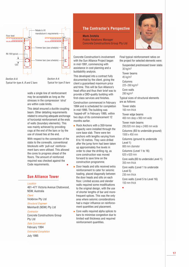
This detail ensured a ductile couplingbeam. Other detailing requirementsrelated to ensuring adequate anchorageof horizontal reinforcement at the endsof walls (boundary elements). Thiswas mainly achieved by providingcogs at the end of the bars or by theuse of closed ties at the end.
With respect to the connection of theslabs to the corewalls, conventionalblockouts with 'pull-out' reinforce-ment bars were utilised. This allowedthe cores to progress ahead of thefloors. The amount of reinforcedrequired was checked against theCode requirements. ■
Concrete Construction’s involvementwith the Sun Alliance Project began in mid-1991, commencing withassistance in cost planning and abuildability analysis.
This developed into a contract fullydocumented by the client, giving theclient a guaranteed maximum priceand time. This will be Sun Alliance’shead office and thus their brief was toprovide a CBD-quality building withfirst-class services and finishes.
Construction commenced in February1994 and is scheduled for completionin mid-1995. The building was'topped-off' in February 1995, withintwo days of its commencement 12months earlier.
■ Rock Anchors with a 350-tonnecapacity were installed through thecore base slab. There were tenanchors with lengths varying from8 to 10 metres. They were drilledafter the jump form had been takenup approximately five levels inorder to clear the drilling rig, ascore construction was movedforward to save time on theconstruction programme.
■ Door heads and sills received extrareinforcement to cater for seismicloading, placed diagonally betweenthe door heads and sills on eachfloor. Limited access and slenderwalls required some modificationsto the original design, with the useof shorter lengths of bar and more-frequent splices. This was the onlyarea where seismic considerationshad a major influence on reinforce-ment quantities and placement.
■ Core walls required alpha splices tobars to minimise congestion due tolimited wall thickness and requiredreinforcement quantities.
Final typical reinforcement ratios onthe project for selected elements were:
Suspended prestressed tower slabs30 kg/m3
Tower beams45 kg/m3
Columns225–260 kg/m3
Core walls280 kg/m3
Typical sizes of structural elementsare as follows:
Tower slabs160 mm thick
Tower edge beams400 mm deep x 900 mm wide
Tower main beams295/320 mm deep x 2400 mm wide
Columns (B3 to underside ground)1500 x 450 mm
Columns (ground to undersideLevel 1)800 mm diameter
Columns (Level 1 to 16)620 x 620 mm
Core walls(B3 to underside Level 1)350 mm thick
Core walls (Level 1 to underside Level 5)230 mm thick
Core walls (Level 5 to Level 16)150 mm thick
■
17
The Contractor’s Perspective
Mark Zvirblis Public Relations Manager Concrete Constructions Group Pty Ltd
Trimmer bars (see schedule)
Trimmer bars (see schedule)
Floor level
R6-100 typical
Rebate to liftmanufacturer's requirements
120
Location 461–471 Victoria Avenue Chatswood,NSW, AustraliaClient Vickbrow Pty LtdStructural Engineer Meinhardt (NSW) Pty LtdContractor Concrete Constructions Group Pty LtdDate Commenced February 1994Estimated Completion
July 1995
Sun Alliance Tower
Section A-ATypical for type A, B and C bars
Section A-ATypical for type D bars
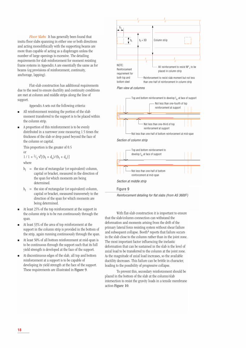
Floor Slabs It has generally been found thatinsitu floor slabs spanning in either one or both directionsand acting monolithically with the supporting beams aremore than capable of acting as a diaphragm unless thenumber of large openings is excessive. The detailingrequirements for slab reinforcement for moment resistingframe systems in Appendix A are essentially the same as forbeams (eg provisions of reinforcement, continuity,anchorage, lapping).
Flat-slab construction has additional requirementsdue to the need to ensure ductility and continuity conditionsare met at column and middle strips along the line ofsupport.
Appendix A sets out the following criteria:
■ All reinforcement resisting the portion of the slabmoment transferred to the support is to be placed withinthe column strip.
■ A proportion of this reinforcement is to be evenlydistributed in a narrower zone measuring 1.5 times thethickness of the slab or drop panel beyond the face ofthe column or capital.
This proportion is the greater of 0.5 or1 / 1 + 2/3 √[(bl + do)/(bt + do)]
where
bl = the size of rectangular (or equivalent) column,capital or bracket, measured in the direction ofthe span for which moments are beingdetermined.
bt = the size of rectangular (or equivalent) column,capital or bracket, measured transversely to thedirection of the span for which moments arebeing determined.
■ At least 25% of the top reinforcement at the support inthe column strip is to be run continuously through thespan.
■ At least 33% of the area of top reinforcement at thesupport in the column strip is provided in the bottom ofthe strip, again running continuously through the span.
■ At least 50% of all bottom reinforcement at mid-span isto be continuous through the support such that its fullyield strength is developed at the face of the support.
■ At discontinuous edges of the slab, all top and bottomreinforcement at a support is to be capable ofdeveloping its yield strength at the face of the support.These requirements are illustrated in Figure 9.
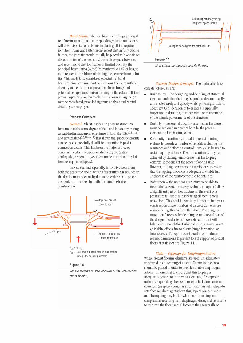
With flat-slab construction it is important to ensurethat the slab/column connection can withstand thedeformation and moments arising from the drift of theprimary lateral force resisting system without shear failureand subsequent collapse. Booth4 reports that failure occursin the slab close to the column rather than in the joint zone.The most important factor influencing the inelasticdeformation that can be sustained in the slab is the level ofaxial load to be transferred to the column at the joint zone.As the magnitude of axial load increases, so the availableductility decreases. This failure can be brittle in character,leading to the possibility of progressive collapse.
To prevent this, secondary reinforcement should beplaced in the bottom of the slab at the column/slabintersection to resist the gravity loads in a tensile membraneaction Figure 10.
18
bt
b1
bt + 3D Column strip
Not less than one-fourth of topreinforcement at support
All reinforcement to resist M*v to beplaced in column strip
Not less than one-third of topreinforcement at support
Top and bottom reinforcement to develop fsy at face of support
Top and bottom reinforcement todevelop fsy at face of support
Reinforcement to resist slab moment but not lessthan one-half of reinforcement in column strip
NOTE:Reinforcementrequirement forboth top andbottom steel
Not less than one-half of bottom reinforcement at mid-span
Not less than one-half of bottomreinforcement at mid-span
Figure 9
Reinforcement detailing for flat slabs (from AS 36002)
Plan view at columns
Section of column strip
Section at middle strip
Band Beams Shallow beams with large principalreinforcement ratios and correspondingly large joint shearswill often give rise to problems in placing all the requiredjoint ties. Irvine and Hutchinson6 report that in fully ductileframes, the joint ties would usually be placed with one tie setdirectly on top of the next set with no clear space between,and recommend that for frames of limited ductility, theprincipal beam ratios (As/bd) be restricted to 0.02 or less, soas to reduce the problems of placing the beam/column jointties. This needs to be considered especially at bandbeam/external column joint connections to ensure sufficientductility in the column to prevent a plastic hinge andpotential collapse mechanism forming in the column. If thisproves impracticable, the mechanism shown in Figure 3cmay be considered, provided rigorous analysis and carefuldetailing are employed.
Precast Concrete
General Whilst loadbearing precast structureshave not had the same degree of field and laboratory testingas cast-insitu structures, experience in both the USA10,11,12
and New Zealand3,7,10 and 13 has shown that precast elementscan be used successfully if sufficient attention is paid toconnection details. This has been the major source ofconcern in certain overseas locations (eg the Spitakearthquake, Armenia, 1988 where inadequate detailing ledto catastrophic collapses).
In New Zealand especially, innovative ideas fromboth the academic and practising fraternities has resulted inthe development of capacity design procedures, and precastelements are now used for both low- and high-riseconstruction.
Seismic Design Concepts The main criteria toconsider obviously are:
■ Buildability – the designing and detailing of structuralelements such that they may be produced economicallyand erected easily and quickly whilst providing structuraladequacy. Consideration of tolerances is especiallyimportant in detailing, together with the maintenanceof the seismic performance of the structure.
■ Ductility – the level of ductility assumed in the designmust be achieved in practice both by the precastelements and their connections.
■ Continuity – continuity is used in precast flooringsystems to provide a number of benefits including fireresistance and deflection control. It may also be used toresist diaphragm forces. Flexural continuity may beachieved by placing reinforcement in the toppingconcrete at the ends of the precast flooring unit.However, the engineer needs to exercise care to ensurethat the topping thickness is adequate to enable fullanchorage of the reinforcement to be obtained.
■ Robustness – the need for a structure to be able tomaintain its overall integrity, without collapse of all ora significant part of the structure in the event of apremature failure of a loadbearing element is wellrecognised. This need is especially important in precastconstruction where numbers of discreet elements areconnected together to form the whole. The designermust therefore consider detailing as an integral part ofthe design in order to achieve a structure that willbehave in a monolithic fashion during a seismic event,eg P-delta effects due to plastic hinge formation, orinter-storey drift require consideration of minimumseating dimensions to prevent loss of support of precastfloors or stair sections Figure 11.
Slabs – Toppings for Diaphragm ActionWhere precast flooring elements are used, an adequatelyreinforced insitu topping of at least 50 mm in thicknessshould be placed in order to provide suitable diaphragmaction. It is essential to ensure that this topping isadequately bonded to the precast elements, if compositeaction is required, by the use of mechanical connectors orchemical (eg epoxy) bonding in conjunction with adequateinterface roughening. Without this, separation can occurand the topping may buckle when subject to diagonalcompression resulting from diaphragm shear, and be unableto transmit the floor inertial forces to the shear walls or
19
Bottom steel acts astension membrane
Top steel causescover to spall
30°
Stretching of bars (yielding)lengthens spans locally
Seating to be designed for potential drift
1
∆/h
Figure 10
Tensile membrane steel at column-slab intersection (from Booth4)
Figure 11
Drift effects on precast concrete flooring
Asb ≥ 2V/øfyAsb = total area of bottom steel in slab passing
through the column perimeter
columns. This was graphically illustrated by the extremelypoor performance of precast framed buildings in theArmenian earthquake of 1988. A major factor in thesefailures was the lack of positive connection between precastfloor-slab elements, and also between these and theirsupporting elements.
Concern as to the adequacy of untopped precastfloors using mechanical connections for diaphragms inseismic conditions have been expressed by several Americanengineers. Clough12 has stated that:
Untopped diaphragms in which inter-elementconnection is made by grouting or mechanicalconnectors, have relatively low in-plane shear strengthand ductility and are most suitable when seismicequilibrium and compatibility forces are small. In zonesof high seismic intensity, or with structural configurationswhich impose large in-plane compatibility forces underlateral load, diaphragms joined by cast-in-placereinforced concrete, either as pour strips or as a topping,usually are more satisfactory.
Designers should ensure that not only is there anadequate load path for the forces that need to be transferredbetween a diaphragm and any lateral-force-resisting elements,such as walls or frames, but that connections are detailedsuch that they adequately transfer the anticipated loads.
The strut and tie method may be used for the designof these details.
Tilt-Up
Tilt-up or loadbearing precast buildings have beena popular form of construction in both Australia and theUnited States for more than 20 years, especially for low-riseindustrial and commercial buildings, and since the mid-1980s also for medium-density residential in Australia.
In the Northridge earthquake, it was reported thatover 400 of the approximately 1200 tilt-up buildings weresignificantly damaged, mainly with partial roof collapses butalso in some cases the collapse of perimeter wall panels14.
However, some significant differences exist in theconstruction of tilt-up buildings between the USA andAustralia/New Zealand. Primarily the differences centrearound the diaphragms. American practice commonly is touse flexible (typically wooden) floors and roofs. The failuresat Northridge were predominantly due to failure of the out-of-plane connections between the perimeter walls and theroof. Most Australian buildings use concrete floors andeither steel truss or concrete roofs. This should give greaterrigidity to these structures under seismic loading due toimproved diaphragm capacity in conjunction with robustdiaphragm-to-wall connections.
However, many buildings in Northridge also usedexpansion anchors to connect diaphragms to walls whichpulled out under repeated cyclic loading. It was observedthat many of these failures occurred adjacent to the shortwalls of long rectangular buildings, rather than the longwalls as might be expected. It is considered15 that this is
because diaphragm capacity is selected on the basis of themaximum shear demand from the design earthquake loads.Therefore the capacity of the diaphragm across the shorterdirection often greatly exceeds the demand based on thedesign earthquake. This additional capacity in turn leads toan additional demand on the connections when theearthquake forces greatly exceed the design loads.
Failures were also observed to be concentrated at re-entrant corners and discontinuities in the diaphragmswhere forces were required to be distributed betweendifferent members.
It is therefore imperative that designers considerdiaphragm/wall connection design and detailing such thatthey might satisfactorily transfer these forces. AS 1170.4Sections 4.2 to 4.4 specify the design forces for whichdiaphragms and their connections should be able towithstand. These conditions are not especially onerous and,as comparison with typical detailing in New Zealand shows,due to the inherent rigidity of the structure, tilt-up buildingsmay be designed and detailed for limited ductility providedsufficient attention is paid to force transfer between panelsand between vertical and horizontal elements.
20
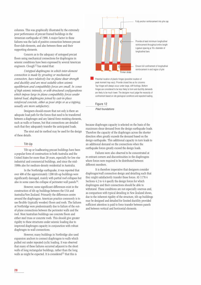
Firmer strata
Figure 12
Piled foundations
Potential location of plastic hinges (possible location of peak moment may vary). Provide closed ties as for columnsTop hinges will always occur under large, stiff footings. Bottomhinges are considered to be less likely to form and ductility demandsare likely to be much lower. The designer must judge the necessity ofconfinement based on site geological conditions and expected loading.
Fully anchor reinforcement into pile cap
Provide at least minimum longitudinalreinforcement throughout entire lengthLigature spacing ≤ 16 x diameter oflongitudinal bars
Ensure full confinement of longitudinalreinforcement in end region of pile
Foundation Systems
General Adequate foundation design is critical forensuring that a building structure will be able to resist boththe gravity loads and seismic forces calculated.
Where there is no possibility for inelastic deforma-tions to develop under earthquake conditions, it is consideredthat standard detailing of reinforcement as for gravity loadsand wind forces will be adequate. This will be the situationin the majority of buildings constructed in Australia.
However, where design indicates the occurrence, orpossible occurrence, of reinforcement yielding during seismicaction, the foundation structure, like the superstructure,must be detailed accordingly. As already mentioned, as aresult of code loading requirements or design decision, theseismic response of the structure may be elastic.
Paulay and Priestly3 suggest foundation systemsthat may support elastic superstructures. Two of these will berelevant to Australian designers;
■ Elastic Foundation Systems In regions of lowseismicity (as is generally the case in Australia) or forlow buildings with structural walls it will be possible todesign and detail the entire structure to respond withinelastic limits.
■ Ductile Foundation Systems In certain cases, thepotential strength of the superstructure with respect tothe specified seismic forces may be excessive (eg largeshear wall structures). The designer might thereforeconsider that it will be preferable for the foundationsystem rather than the superstructure to be the principalsource of energy dissipation during inelastic response. Apotential drawback for this system is that damage mayoccur during moderately strong earthquakes. Largecracks may form if yielding of reinforcement hasoccurred. Further, repairs to foundations may bedifficult and costly if required below the water table.
Foundation Structures for Frames As discussedin Design Methodology, AS 3600 provides some limitedguidance regarding footing design and detailing. Althoughthe code stipulates that for foundations located in soils witha maximum bearing capacity of less than 250 kPa, restraintmust be provided in the horizontal direction to limitdifferential movement during an earthquake. It should benoted that reports from Kobe indicate that althoughliquefaction is a problem in poor soils, the water in thesaturated reclaimed areas acted as a dampener, restrictingdamage to significantly less than that experienced in theadjoining 'dry soil' areas.
The Code considers that there is no possibility forinelastic deformations to develop under earthquake loading,and that standard detailing of footings for gravity and wind-induced loads only will be sufficient. However, the authorconsiders that certain additional precautions can bewarranted.
Isolated Footings These can prevent a problemwith rocking or tipping if a plastic hinge forms in the base ofthe column. Unless precautions are taken, permanentdeformation of the foundation can occur due to plasticdeformation of the soil despite both the column and footingremaining elastic. The detailing of the column/footing jointmust be carefully considered.
Combined Footings It may prove more feasibleto absorb large moments transmitted by plastic hinges atcolumn bases by using stiff tie beams between footings,whereby a high degree of elastic restraint against columnrotations can be provided. In fact this detail is such thatreinforcement yielding is unlikely to occur and it isconsidered that no special detailing requirements forductility need be provided. It would, however, be necessaryfor the tie beams to have sufficient reserve strength over thatof the hinging columns – see Design Methodology –Capacity Design.
If it is required to reduce the bearing pressure underthe footing pads, they may be joined to provide onecontinuous footing.
Stub columns do require special consideration ifinelastic deformations and shear failure are to be avoided.Paulay and Priestley3 consider that plastic hinges shouldtherefore be restricted to the column section immediatelyabove the beam.
Piled Foundations Piled systems supportingstructural walls may be subject to large concentrated forcesdue to overturning moments and shear forces. Carefuldesign is therefore required.
Detailing of reinforced concrete piles should followthe recommendations set out above for columns. The endregion of a pile under the foundation structure should bedetailed to ensure full confinement of the longitudinalreinforcement using closed or helical ties. The locations ofpeak moments in the pile may necessitate the lengthconfinement being considerably extended. Further, even ifcalculations indicate no tension loads, it is recommendedthat minimum longitudinal reinforcement be provided. Thearrangement of longitudinal reinforcement should be as forcolumns, and the reinforcement should be fully anchoredwithin the pile cap. In non-critical regions, nominaltransverse ties or spiral hoops should be provided. Paulayand Priestley3 recommend that vertical spacing not exceed16 times the diameter of longitudinal bars Figure 12.
21
Conclusions
Australia is an area of moderate seismicity and lowrisk in comparison to California, Japan and New Zealand.The provisions for both the design and detailing of reinforcedconcrete structures in Australian codes reflect this.
The detailing requirements therefore are not onerousand loose-bar detailing and efficient fabrication techniquescurrently used (as recommended in the CIA detailingmanual8) are still adequate and with little additionalconsideration will provide the levels of ductility andcontinuity of reinforcement to enable the structure tosatisfactorily weather anticipated earthquake loading inAustralia.
It is important to provide a minimum level ofductility in both beams and columns framing into a joint,and to ensure adequate confinement of column steel (evenif not beam steel as there is a certain level of redundancydue to the presence of slab reinforcement) regardless of thetype of structural system employed.
It is strongly recommended that columns in, forinstance, shear wall or ordinary moment resisting framesystems that are not deemed to require detailing to AppendixA, should still be detailed so that buckling of bars will notoccur. As noted above, magnitudes of earthquakes aredifficult to predict with accuracy. Should an earthquakeoccur of significantly greater magnitude than that whichhas been designed for (at least a statistical possibility),brittle failure and collapse could occur.
With a limited additional quantity of properlydetailed extra ligatures and continuity reinforcement, plastichinges can be induced to form at a given load. However,yielding will be ductile (gradual), even if the designearthquake load is exceeded (ie the hinge will act as a 'fuse'preventing transfer of the larger forces).
The choice for the designer/detailer is clear. A fullyelastic response by the structure, whilst allowed by the Code,cannot be guaranteed. Therefore, to prevent catastrophiccollapse and probable loss of life under a greater thandesigned-for event, a ductile failure must be ensured. Thisminimum required level of ductility can be readily achievedby judicious detailing in selected areas.
Precast concrete construction requires some specialcare in detailing to ensure that floors, especially, will act asdiaphragms (if so designed) in order to properly transferhorizontal forces. Further consideration is required withmixed precast and insitu construction to ensure monolithicbehaviour.
Compatible overseas experience has shownreinforced concrete, both insitu and precast, to be aneminently suitable and cost-effective solution for buildingstructures in low to medium seismic zones such as Australia.Designers and specifiers can remain confident of reinforcedconcrete’s ability to functionally and elegantly meet theneeds of today's construction industry.
■
References
1 Standards Australia, AS 1170.4–1993 Minimum DesignLoads on Structures, Part 4: Earthquake Loads.
2 Standards Australia, AS 3600–1994 Concrete Structures.
3 Paulay, T and Priestley, M J N Seismic Design ofReinforced Concrete and Masonry Buildings JohnWiley & Sons Inc, 1992.
4 Booth, E (ed) Concrete Structures in EarthquakeRegions: Design and Analysis Longman, 1994.
5 American Concrete Institute, ACI 318–89 (revised 1992)Building Code Requirements for Reinforced Concreteand ACI 318–89R (revised 1992) commentary Chapter21 Special Provisions for Seismic Design.
6 Irvine, H Max and Hutchinson, G L (eds) AustralianEarthquake Engineering Manual 3rd Edition,Techbooks, 1993.
7 Park, R Precast Concrete in Seismic-Resisting BuildingFrames in New Zealand Concrete International,November 1990.
8 Recommended Practice – Reinforcement DetailingHandbook (Z6), Concrete Institute of Australia, 1988.
9 Goldsworthy, H M Earthquake Resistant Design ofConcrete Structures: Design and Detailing Require-ments in AS 3600–1994, Appendix A for MomentResisting Frames University of Melbourne, 1994.
10 Park, R Trends, Innovation and Performance ofPrecast Concrete in Buildings Third InternationalConference on Concrete Engineering and Technology,Kuala Lumpur, 1993.
11 Brooks, H S E Tilt-Up and Earthquakes – A Post-Northridge Assessment.
12 Clough, D P Considerations in the Design of PrecastConcrete for Earthquake Loads Journal of PrestressedConcrete Institute, Vol. 27, No. 2, Mar–Apr 1982, pp 618–639.
13 New Zealand Concrete Society & New Zealand NationalSociety for Earthquake Engineering Guidelines for theUse of Structural Precast Concrete in Buildings 1991.
14 Brooks, S E Tilt-Up and Earthquakes: A Post-Northridge Assessment 1994.
15 Ferner, H The Northridge Building Case Study ProjectNZNSEE Conference, 1995.
16 Paulay, T The Design of Ductile Reinforced ConcreteStructural Walls for Earthquake Resistance.
17 Case History Report – Northbridge, CaliforniaEarthquake CRSI, Bulletin No. 46, 1994.
22
AD
AP
TE
D
TO
E
LE
CT
RO
NI
C
FO
RM
B
Y
TE
CH
ME
DI
A
PU
BL
IS
HI
NG
P
TY
L
TD
+
61
2
9
47
7
77
66
RCD D4JUNE 95
CONTACT DETAILS
SRIA NATIONAL OFFICEPO BOX 280 CROWS NEST NSW 2065
TELEPHONE: 02 9929 3033FREE CALL: 1300 300 114FACSIMILE: 02 9929 3255
EMAIL: [email protected]: www.sria.com.au
STEELREINFORCEMENTINSTITUTE OFAUSTRALIA