Embed Size (px)
Citation preview
FEMA 451B Topic 12 Notes Masonry Structures 12 - 1
Instructional Material Complementing FEMA 451, Design Examples Design of Masonry Structures 12 - 1
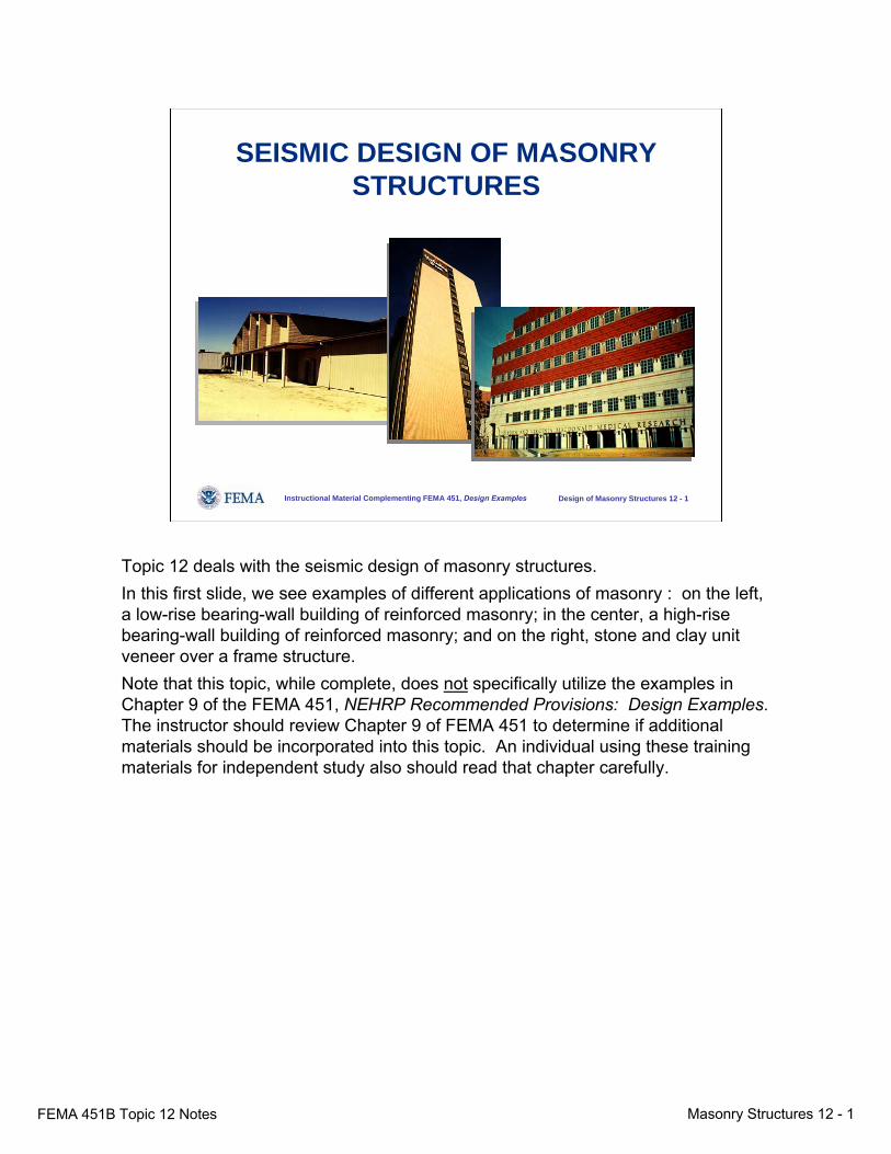
SEISMIC DESIGN OF MASONRY STRUCTURES
Topic 12 deals with the seismic design of masonry structures. In this first slide, we see examples of different applications of masonry : on the left, a low-rise bearing-wall building of reinforced masonry; in the center, a high-rise bearing-wall building of reinforced masonry; and on the right, stone and clay unit veneer over a frame structure.Note that this topic, while complete, does not specifically utilize the examples in Chapter 9 of the FEMA 451, NEHRP Recommended Provisions: Design Examples. The instructor should review Chapter 9 of FEMA 451 to determine if additional materials should be incorporated into this topic. An individual using these training materials for independent study also should read that chapter carefully.
FEMA 451B Topic 12 Notes Masonry Structures 12 - 2
Instructional Material Complementing FEMA 451, Design Examples Design of Masonry Structures 12 - 2
NEHRP Recommended ProvisionsMasonry Design
● Context in the NEHRP Recommended Provisions● Masonry behavior● Reference standards● Seismic resisting systems● Component design● Quality assurance● Summary
This is a list of topics covered in this review module on masonry design according to the NEHRP Recommended Provisions, which is developed for the Federal Emergency Management Agency (FEMA) by the Building Seismic Safety Council (BSSC) of the National Institute of Building Sciences (NIBS).
FEMA 451B Topic 12 Notes Masonry Structures 12 - 3
Instructional Material Complementing FEMA 451, Design Examples Design of Masonry Structures 12 - 3
Objectives of Module
● Basics of masonry behavior ● Basics of masonry specification● The MSJC code and specification and their relationship
to the NEHRP Recommended Provisions documents● Earthquake design of masonry structures and
components using the 2005 MSJC code and specification
● Example of masonry shear wall design
Because many in the intended audience may not have studied masonry recently, the module begins with a review of the basic components of masonry and of the basic behavior of wall-type structures. It then addresses the specification of masonry units, mortar, grout, and accessory materials. It continues with the rudiments of the mechanical behavior of masonry. It then reviews the Masonry Standards Joint Committee (MSJC) Code and Specification, which is the fundamental technical resource behind the NEHRP Recommended Provisions. It concludes with the design and detailing of a reinforced masonry shear wall.
FEMA 451B Topic 12 Notes Masonry Structures 12 - 4
Instructional Material Complementing FEMA 451, Design Examples Design of Masonry Structures 12 - 4
Context in the NEHRP Recommended Provisions
● Design seismic loads– Load combinations Chap. 5– Loads on structures Chap. 5– Loads on components & attachments Chap. 6
● Design resistances Chap. 11– Strength design (mostly references the 2002 MSJC)
Provisions Chapters 5 and 6 are used to determine load combination and total base shear, seismic load analysis, and additional minimum levels of design force requirements for components and attachments. Chapter 11 is used to select masonry designs with adequate strength to meet demand and specifies detailing for ductility. Note that the load combination from the Provisions must be used.
FEMA 451B Topic 12 Notes Masonry Structures 12 - 5
Instructional Material Complementing FEMA 451, Design Examples Design of Masonry Structures 12 - 5
grout
steel reinforcing
bars
units of concrete or fired clay
mortar
grout... typical
materials in reinforced
masonry
... typical ... typical materials in materials in
reinforced reinforced masonrymasonry
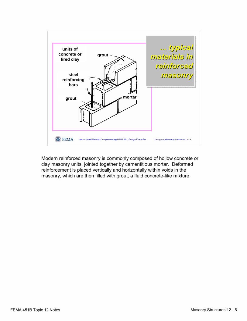
Modern reinforced masonry is commonly composed of hollow concrete or clay masonry units, jointed together by cementitious mortar. Deformed reinforcement is placed vertically and horizontally within voids in the masonry, which are then filled with grout, a fluid concrete-like mixture.
FEMA 451B Topic 12 Notes Masonry Structures 12 - 6
Instructional Material Complementing FEMA 451, Design Examples Design of Masonry Structures 12 - 6
Essential Elements of Simplified Design for Wall-type Structures
● Starting point for design● Design of vertical strips in walls perpendicular to
lateral loads● Design of walls parallel to lateral loads● Design of lintels● Simplified analysis for lateral loads● Design of diaphragms● Detailing
Most practicing engineers are very familiar with the behavior of frame-type structures. Many, however, may never have formally studied the behavior of wall-type structures. For that reason, it is appropriate to review that behavior. The following series of slides presents the basic starting point for design of wall-type structures and their components.
FEMA 451B Topic 12 Notes Masonry Structures 12 - 7
Instructional Material Complementing FEMA 451, Design Examples Design of Masonry Structures 12 - 7
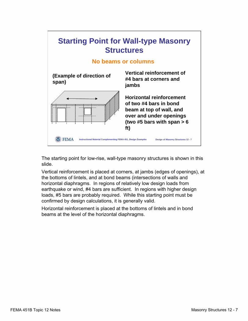
Starting Point for Wall-type Masonry Structures
(Example of direction of span)
Vertical reinforcement of #4 bars at corners and jambs
Horizontal reinforcement of two #4 bars in bond beam at top of wall, and over and under openings (two #5 bars with span > 6 ft)
No beams or columns
The starting point for low-rise, wall-type masonry structures is shown in this slide. Vertical reinforcement is placed at corners, at jambs (edges of openings), at the bottoms of lintels, and at bond beams (intersections of walls and horizontal diaphragms. In regions of relatively low design loads from earthquake or wind, #4 bars are sufficient. In regions with higher design loads, #5 bars are probably required. While this starting point must be confirmed by design calculations, it is generally valid.Horizontal reinforcement is placed at the bottoms of lintels and in bond beams at the level of the horizontal diaphragms.
FEMA 451B Topic 12 Notes Masonry Structures 12 - 8
Instructional Material Complementing FEMA 451, Design Examples Design of Masonry Structures 12 - 8
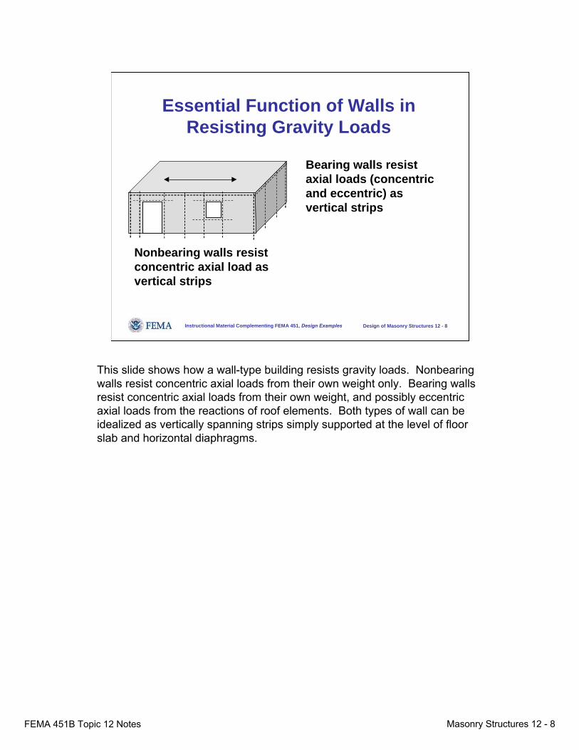
Essential Function of Walls in Resisting Gravity Loads
Nonbearing walls resist concentric axial load as vertical strips
Bearing walls resist axial loads (concentric and eccentric) as vertical strips
This slide shows how a wall-type building resists gravity loads. Nonbearing walls resist concentric axial loads from their own weight only. Bearing walls resist concentric axial loads from their own weight, and possibly eccentric axial loads from the reactions of roof elements. Both types of wall can be idealized as vertically spanning strips simply supported at the level of floor slab and horizontal diaphragms.
FEMA 451B Topic 12 Notes Masonry Structures 12 - 9
Instructional Material Complementing FEMA 451, Design Examples Design of Masonry Structures 12 - 9
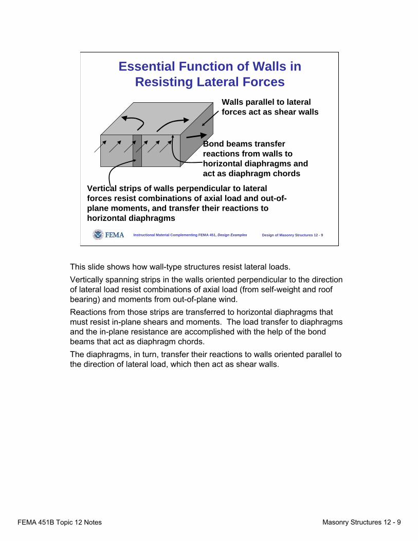
Essential Function of Walls in Resisting Lateral Forces
Walls parallel to lateral forces act as shear walls
Vertical strips of walls perpendicular to lateral forces resist combinations of axial load and out-of-plane moments, and transfer their reactions to horizontal diaphragms
Bond beams transfer reactions from walls to horizontal diaphragms and act as diaphragm chords
This slide shows how wall-type structures resist lateral loads. Vertically spanning strips in the walls oriented perpendicular to the direction of lateral load resist combinations of axial load (from self-weight and roof bearing) and moments from out-of-plane wind. Reactions from those strips are transferred to horizontal diaphragms that must resist in-plane shears and moments. The load transfer to diaphragms and the in-plane resistance are accomplished with the help of the bond beams that act as diaphragm chords. The diaphragms, in turn, transfer their reactions to walls oriented parallel to the direction of lateral load, which then act as shear walls.
FEMA 451B Topic 12 Notes Masonry Structures 12 - 10
Instructional Material Complementing FEMA 451, Design Examples Design of Masonry Structures 12 - 10
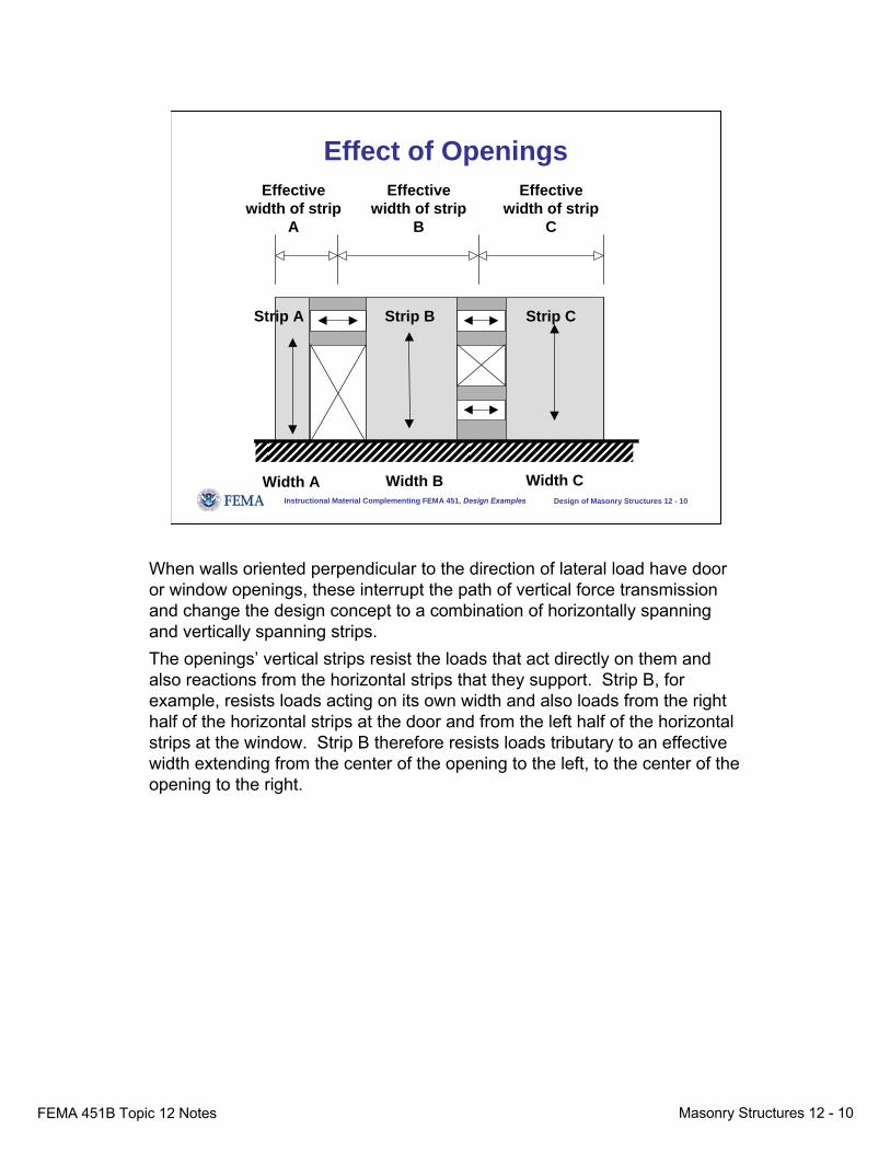
Effect of Openings
Strip A
Effective width of strip
A
Width A
Effective width of strip
B
Effective width of strip
C
Strip B Strip C
Width B Width C
When walls oriented perpendicular to the direction of lateral load have door or window openings, these interrupt the path of vertical force transmission and change the design concept to a combination of horizontally spanning and vertically spanning strips. The openings’ vertical strips resist the loads that act directly on them and also reactions from the horizontal strips that they support. Strip B, for example, resists loads acting on its own width and also loads from the right half of the horizontal strips at the door and from the left half of the horizontal strips at the window. Strip B therefore resists loads tributary to an effective width extending from the center of the opening to the left, to the center of the opening to the right.

FEMA 451B Topic 12 Notes Masonry Structures 12 - 11
Instructional Material Complementing FEMA 451, Design Examples Design of Masonry Structures 12 - 11
Effect of Openings
Openings increase original design actions on each strip by a factor equal to the ratio of the effective width of the strip divided by the actual width:
EffectiveWidth BActions in Strip B Original ActionsActual Width B
⎛ ⎞= ⎜ ⎟
⎝ ⎠
Openings in effect increase the original design actions on each strip by a factor equal to the ratio of the effective width of the strip divided by the actual width. This is precise for wind loads. It is usually conservative for seismic loads because the masses associated with doors and windows are often less than those associated with walls.Basically, because the openings don’t change the loads on the wall, the wall’s required vertical reinforcement remains the same, and the designer must simply move that steel horizontally so that it does not coincide with the openings.
FEMA 451B Topic 12 Notes Masonry Structures 12 - 12
Instructional Material Complementing FEMA 451, Design Examples Design of Masonry Structures 12 - 12
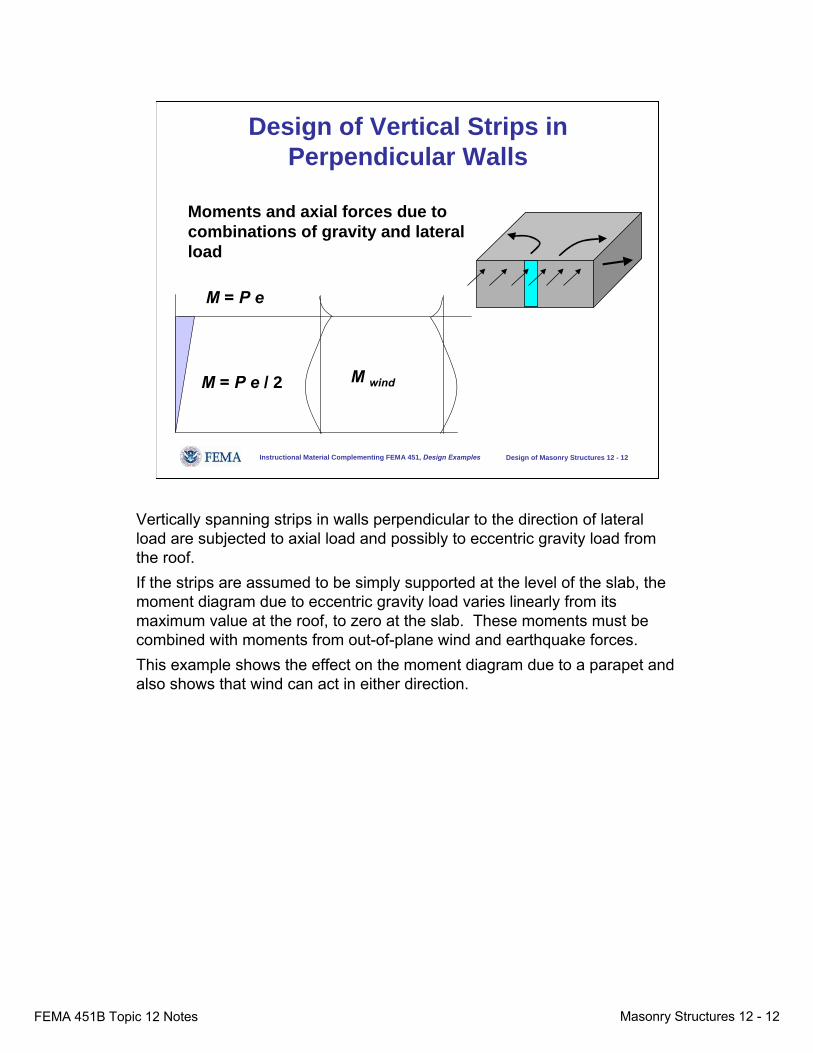
Design of Vertical Strips in Perpendicular Walls
Moments and axial forces due to combinations of gravity and lateral load
M = P e
M = P e / 2 M wind
Vertically spanning strips in walls perpendicular to the direction of lateral load are subjected to axial load and possibly to eccentric gravity load from the roof. If the strips are assumed to be simply supported at the level of the slab, the moment diagram due to eccentric gravity load varies linearly from its maximum value at the roof, to zero at the slab. These moments must be combined with moments from out-of-plane wind and earthquake forces. This example shows the effect on the moment diagram due to a parapet and also shows that wind can act in either direction.
FEMA 451B Topic 12 Notes Masonry Structures 12 - 13
Instructional Material Complementing FEMA 451, Design Examples Design of Masonry Structures 12 - 13
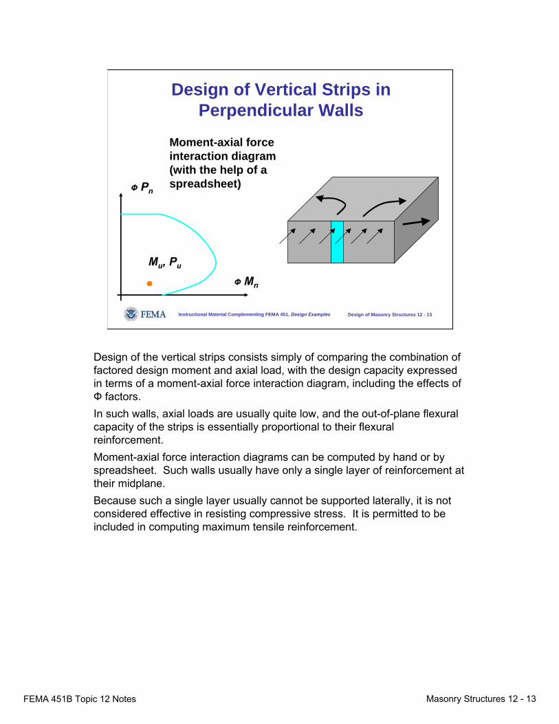
Design of Vertical Strips in Perpendicular Walls
Ф Pn
Ф Mn
Mu, Pu
Moment-axial force interaction diagram (with the help of a spreadsheet)
Design of the vertical strips consists simply of comparing the combination of factored design moment and axial load, with the design capacity expressed in terms of a moment-axial force interaction diagram, including the effects of Ф factors. In such walls, axial loads are usually quite low, and the out-of-plane flexural capacity of the strips is essentially proportional to their flexural reinforcement. Moment-axial force interaction diagrams can be computed by hand or by spreadsheet. Such walls usually have only a single layer of reinforcement at their midplane. Because such a single layer usually cannot be supported laterally, it is not considered effective in resisting compressive stress. It is permitted to be included in computing maximum tensile reinforcement.
FEMA 451B Topic 12 Notes Masonry Structures 12 - 14
Instructional Material Complementing FEMA 451, Design Examples Design of Masonry Structures 12 - 14
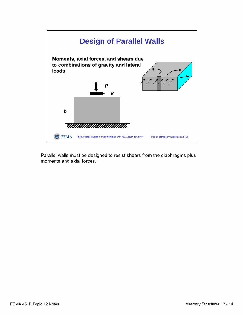
Design of Parallel Walls
Moments, axial forces, and shears due to combinations of gravity and lateral loads
PV
h
Parallel walls must be designed to resist shears from the diaphragms plus moments and axial forces.
FEMA 451B Topic 12 Notes Masonry Structures 12 - 15
Instructional Material Complementing FEMA 451, Design Examples Design of Masonry Structures 12 - 15
Design of Parallel Walls
Φ Pn
Φ Mn
Mu, Pu
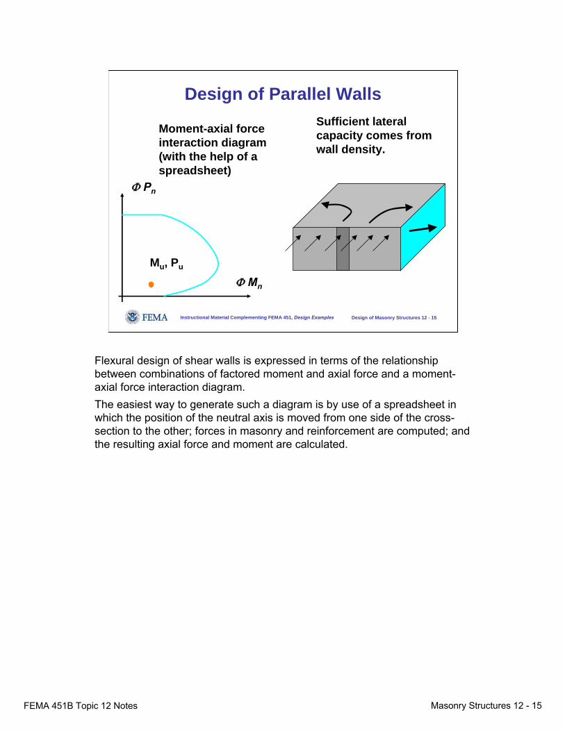
Moment-axial force interaction diagram (with the help of a spreadsheet)
Sufficient lateral capacity comes from wall density.
Flexural design of shear walls is expressed in terms of the relationship between combinations of factored moment and axial force and a moment-axial force interaction diagram. The easiest way to generate such a diagram is by use of a spreadsheet in which the position of the neutral axis is moved from one side of the cross-section to the other; forces in masonry and reinforcement are computed; and the resulting axial force and moment are calculated.

FEMA 451B Topic 12 Notes Masonry Structures 12 - 16
Instructional Material Complementing FEMA 451, Design Examples Design of Masonry Structures 12 - 16
Design of Parallel Walls
Shearing resistance:
'4.0 1.75 0.25
n m s
um n m u
u v
V V V
MV A f PV d
= +
⎡ ⎤⎛ ⎞= − +⎢ ⎥⎜ ⎟⎢ ⎥⎝ ⎠⎣ ⎦
The shear design of shear walls is quite similar to that of reinforced concrete shear walls. Nominal resistance is taken as the summation of resistance from masonry plus the resistance from shear reinforcement. Nominal resistance due to masonry is considered to vary with the aspect ratio of the element. Capacity design is required for shear walls -- they must either be designed for a design strength at least equal to 1.25 times the shear associated with development of the nominal flexural strength or for a nominal strength at least equal to 2.5 times the required shear strength.Because the nondimensional aspect ratio need not be taken greater than 1.0, nominal resistance due to masonry varies from 2.25 to 4.0 times the product of the area and the square root of the specified compressive strength of the masonry.
FEMA 451B Topic 12 Notes Masonry Structures 12 - 17
Instructional Material Complementing FEMA 451, Design Examples Design of Masonry Structures 12 - 17
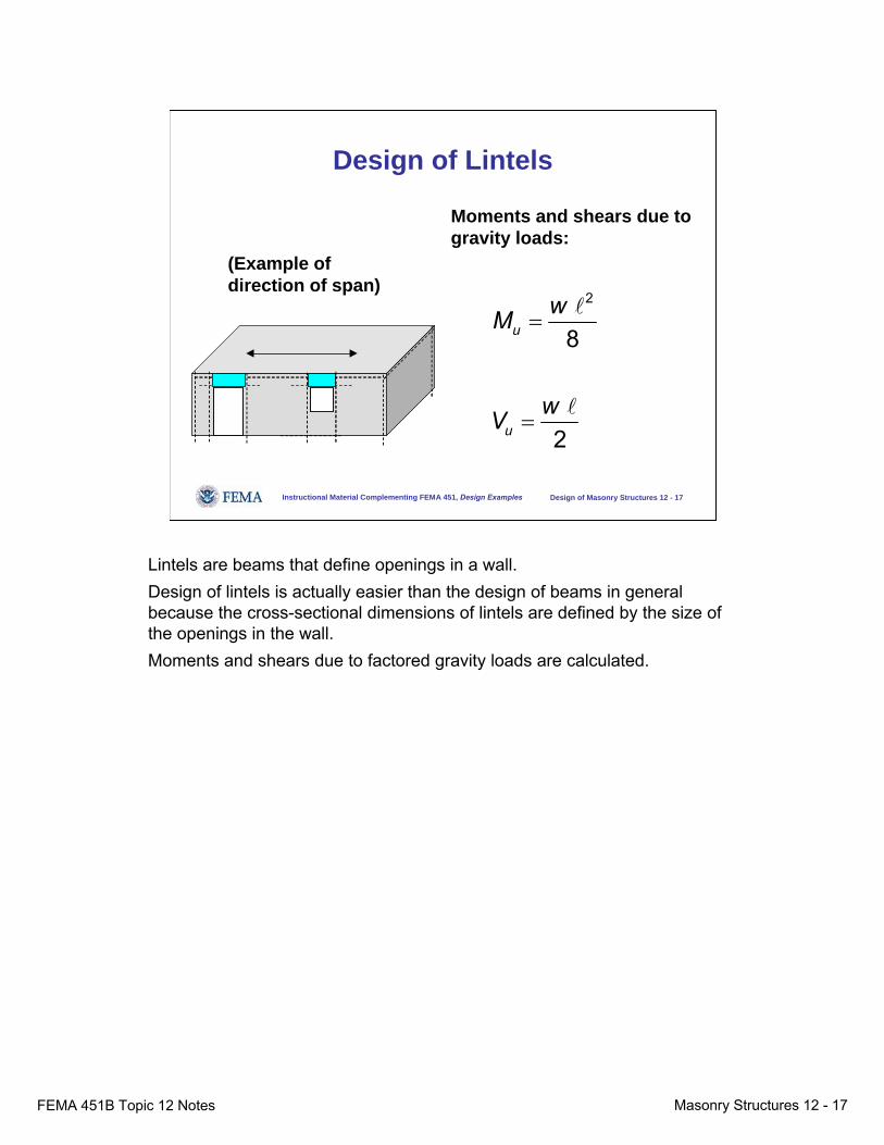
Design of Lintels
(Example of direction of span)
Moments and shears due to gravity loads:
2
8
2
u
u
wM
wV
=
=
l
l
Lintels are beams that define openings in a wall. Design of lintels is actually easier than the design of beams in general because the cross-sectional dimensions of lintels are defined by the size of the openings in the wall. Moments and shears due to factored gravity loads are calculated.

FEMA 451B Topic 12 Notes Masonry Structures 12 - 18
Instructional Material Complementing FEMA 451, Design Examples Design of Masonry Structures 12 - 18
Design of Lintels
Shear design: Provide enough depth so that shear reinforcement is not needed.
0.9u
sy
MAf dφ
≈× ×
Flexural design:
d
As
Neutral axis
Design of the lintel for shear is quite simple. Because shear reinforcement is impractical for masonry lintels, the designer simply checks that the architecturally defined depth and width of the lintel give sufficient cross-sectional area so that shear reinforcement is unnecessary. Lintels should be grouted solid.Flexural design is also quite simple. Approximating the internal lever arm (distance between resultants of tensile and compressive forces in the section) as 0.9 d, the required area of longitudinal reinforcement is calculated as the factored design moment divided by the product of the lever arm and the specified yield strength of the reinforcement.
FEMA 451B Topic 12 Notes Masonry Structures 12 - 19
Instructional Material Complementing FEMA 451, Design Examples Design of Masonry Structures 12 - 19
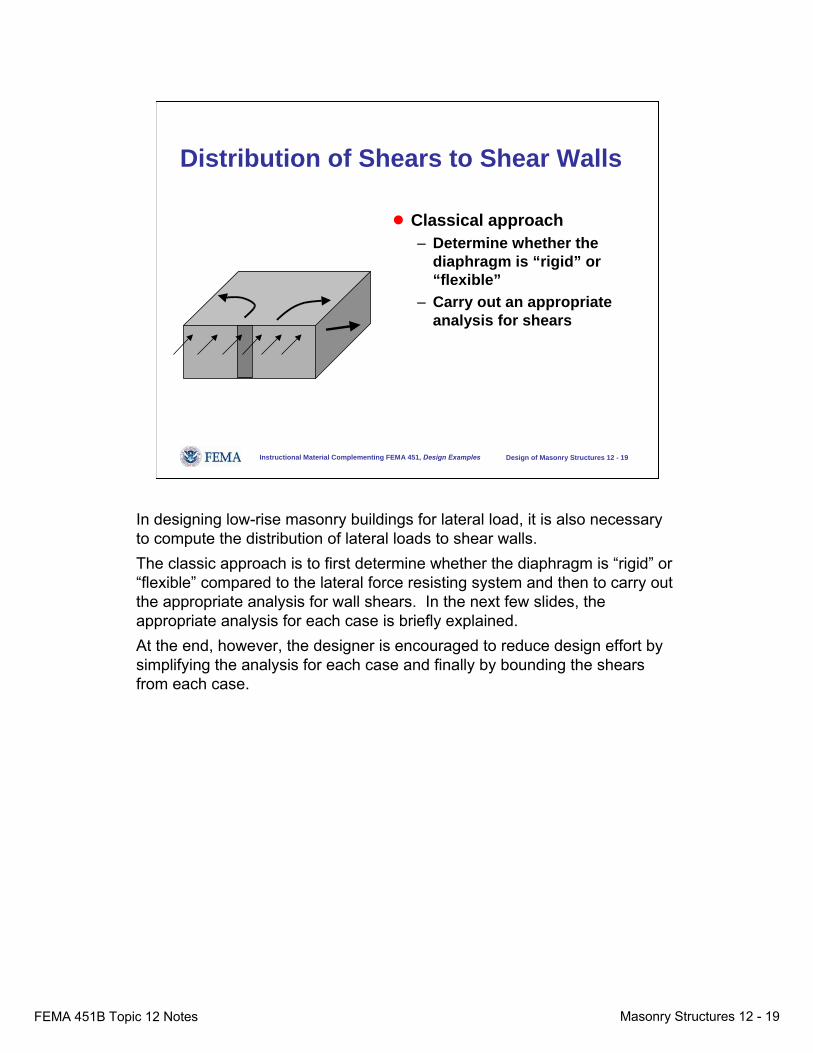
Distribution of Shears to Shear Walls
● Classical approach– Determine whether the
diaphragm is “rigid” or “flexible”
– Carry out an appropriate analysis for shears
In designing low-rise masonry buildings for lateral load, it is also necessary to compute the distribution of lateral loads to shear walls. The classic approach is to first determine whether the diaphragm is “rigid” or “flexible” compared to the lateral force resisting system and then to carry out the appropriate analysis for wall shears. In the next few slides, the appropriate analysis for each case is briefly explained. At the end, however, the designer is encouraged to reduce design effort by simplifying the analysis for each case and finally by bounding the shears from each case.
FEMA 451B Topic 12 Notes Masonry Structures 12 - 20
Instructional Material Complementing FEMA 451, Design Examples Design of Masonry Structures 12 - 20
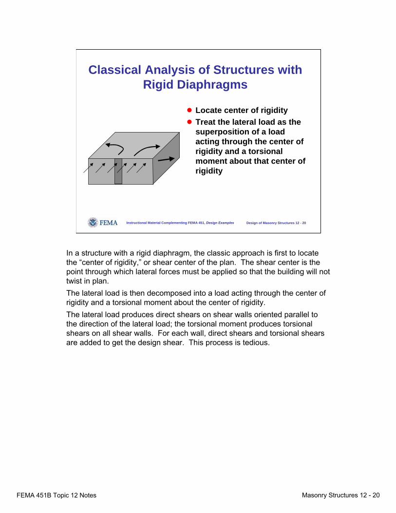
Classical Analysis of Structures with Rigid Diaphragms
● Locate center of rigidity● Treat the lateral load as the
superposition of a load acting through the center of rigidity and a torsional moment about that center of rigidity
In a structure with a rigid diaphragm, the classic approach is first to locate the “center of rigidity,” or shear center of the plan. The shear center is the point through which lateral forces must be applied so that the building will not twist in plan. The lateral load is then decomposed into a load acting through the center of rigidity and a torsional moment about the center of rigidity. The lateral load produces direct shears on shear walls oriented parallel to the direction of the lateral load; the torsional moment produces torsional shears on all shear walls. For each wall, direct shears and torsional shears are added to get the design shear. This process is tedious.
FEMA 451B Topic 12 Notes Masonry Structures 12 - 21
Instructional Material Complementing FEMA 451, Design Examples Design of Masonry Structures 12 - 21
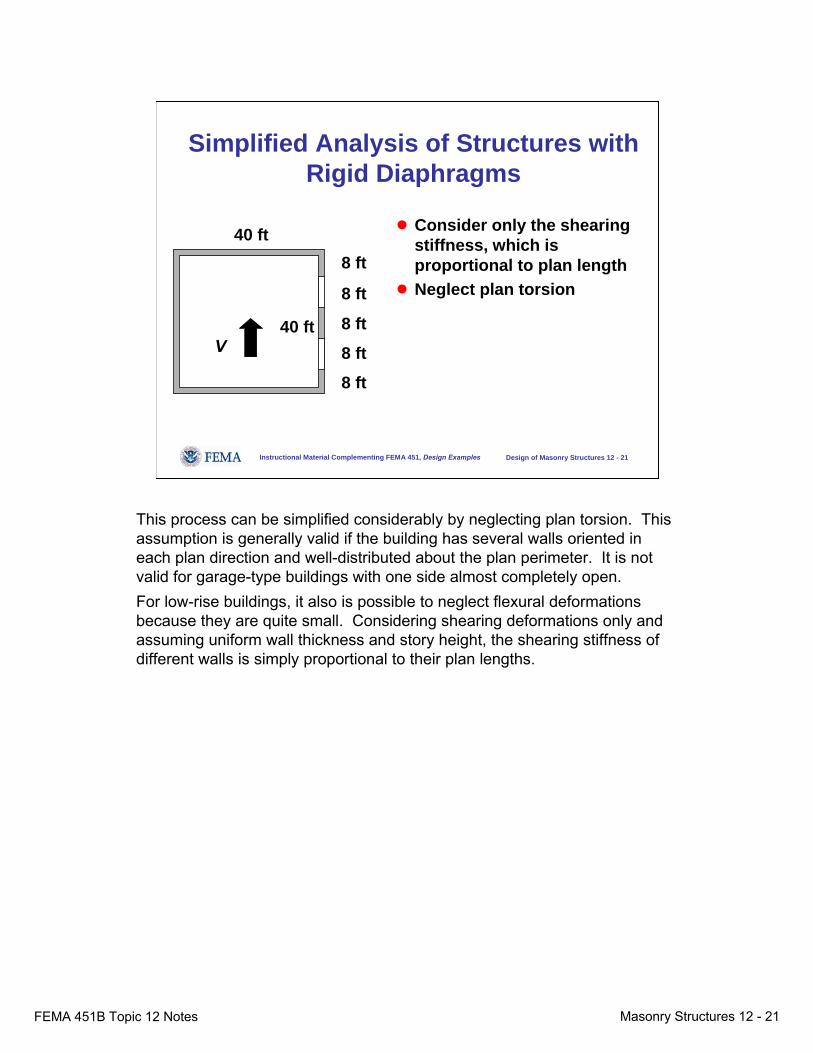
Simplified Analysis of Structures with Rigid Diaphragms
● Consider only the shearing stiffness, which is proportional to plan length
● Neglect plan torsion
40 ft8 ft
40 ft
8 ft
8 ft
8 ft
8 ft
V
This process can be simplified considerably by neglecting plan torsion. This assumption is generally valid if the building has several walls oriented in each plan direction and well-distributed about the plan perimeter. It is not valid for garage-type buildings with one side almost completely open. For low-rise buildings, it also is possible to neglect flexural deformations because they are quite small. Considering shearing deformations only and assuming uniform wall thickness and story height, the shearing stiffness of different walls is simply proportional to their plan lengths.
FEMA 451B Topic 12 Notes Masonry Structures 12 - 22
Instructional Material Complementing FEMA 451, Design Examples Design of Masonry Structures 12 - 22
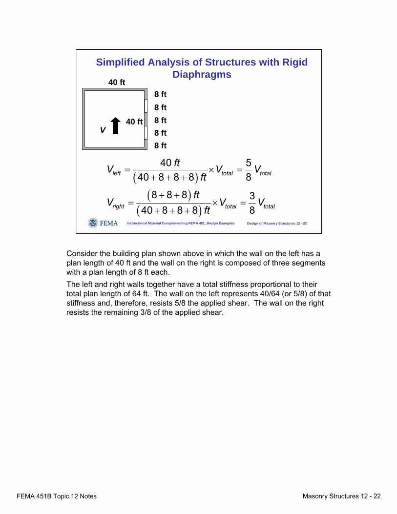
Simplified Analysis of Structures with Rigid Diaphragms
( )( )
( )
40 540 8 8 8 8
8 8 8 340 8 8 8 8
left total total
right total total
ftV V Vft
ftV V V
ft
= × =+ + +
+ += × =
+ + +
40 ft8 ft
40 ft
8 ft8 ft8 ft8 ft
V
Consider the building plan shown above in which the wall on the left has a plan length of 40 ft and the wall on the right is composed of three segments with a plan length of 8 ft each.The left and right walls together have a total stiffness proportional to their total plan length of 64 ft. The wall on the left represents 40/64 (or 5/8) of that stiffness and, therefore, resists 5/8 the applied shear. The wall on the right resists the remaining 3/8 of the applied shear.
FEMA 451B Topic 12 Notes Masonry Structures 12 - 23
Instructional Material Complementing FEMA 451, Design Examples Design of Masonry Structures 12 - 23
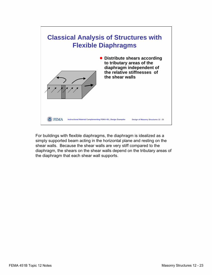
Classical Analysis of Structures with Flexible Diaphragms
● Distribute shears according to tributary areas of the diaphragm independent of the relative stiffnesses of the shear walls
For buildings with flexible diaphragms, the diaphragm is idealized as a simply supported beam acting in the horizontal plane and resting on the shear walls. Because the shear walls are very stiff compared to the diaphragm, the shears on the shear walls depend on the tributary areas of the diaphragm that each shear wall supports.
FEMA 451B Topic 12 Notes Masonry Structures 12 - 24
Instructional Material Complementing FEMA 451, Design Examples Design of Masonry Structures 12 - 24
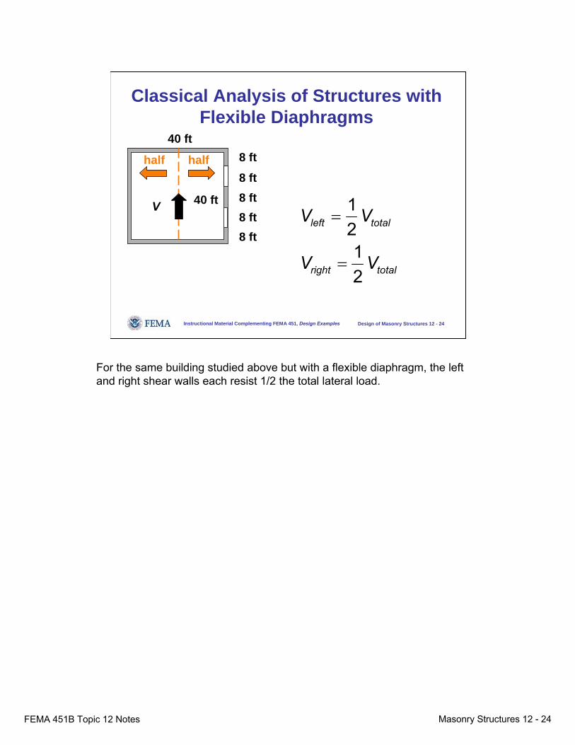
Classical Analysis of Structures with Flexible Diaphragms
40 ft8 ft
40 ft
8 ft8 ft8 ft8 ft
1212
left total
right total
V V
V V
=
=
half half
V
For the same building studied above but with a flexible diaphragm, the left and right shear walls each resist 1/2 the total lateral load.

FEMA 451B Topic 12 Notes Masonry Structures 12 - 25
Instructional Material Complementing FEMA 451, Design Examples Design of Masonry Structures 12 - 25
Simplified Diaphragm Analysis
Design for the worse of the two cases:
5 / 8 V1 / 2 V
3 / 8 V1 / 2 V
40 ft8 ft
40 ft
8 ft8 ft8 ft8 ft
V
Further, it is possible to avoid the need to classify the diaphragm as “rigid” or “flexible.” Simply design each wall for the more critical of the simplified rigid-diaphragm case and the flexible-diaphragm case. For this example, the left-hand wall had a shear of 2/3 V for the rigid-diaphragm case and a shear of 1/2 V for the flexible-diaphragm case. It could therefore be designed for the more severe of the two design shears or 2/3 V. The right-hand wall would be similarly designed for the worse of 1/3 V (rigid) and 1/2 V (flexible) or 1/2 V. Even though these two design shears sum to more than V, the design is conservative and valid. It might be too conservative for a few cases in which event the diaphragm stiffness would have to be evaluated.
FEMA 451B Topic 12 Notes Masonry Structures 12 - 26
Instructional Material Complementing FEMA 451, Design Examples Design of Masonry Structures 12 - 26
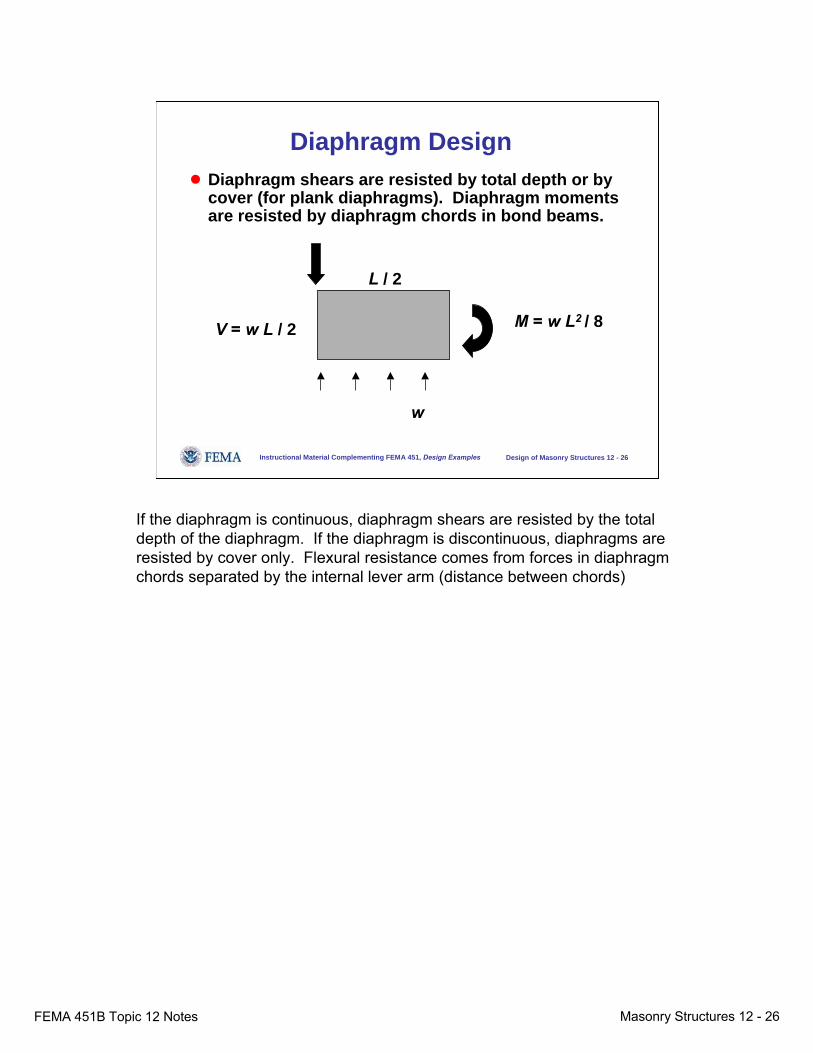
Diaphragm Design● Diaphragm shears are resisted by total depth or by
cover (for plank diaphragms). Diaphragm moments are resisted by diaphragm chords in bond beams.
w
L / 2
M = w L2 / 8V = w L / 2
If the diaphragm is continuous, diaphragm shears are resisted by the total depth of the diaphragm. If the diaphragm is discontinuous, diaphragms are resisted by cover only. Flexural resistance comes from forces in diaphragm chords separated by the internal lever arm (distance between chords)
FEMA 451B Topic 12 Notes Masonry Structures 12 - 27
Instructional Material Complementing FEMA 451, Design Examples Design of Masonry Structures 12 - 27
Details
● Wall-diaphragm connections● Design of lintels for out-of-plane loads between wall-
diaphragm connections● Connections between bond beam and walls● Connections between walls and foundation
After designing the out-of-plane strips, the in-plane shear walls and the lintels, additional details would have to be addressed: wall-diaphragm connections, design of lintels for out-of-plane loads between wall-diaphragm connections, connections between bond beam and walls, and connections between walls and foundations.
FEMA 451B Topic 12 Notes Masonry Structures 12 - 28
Instructional Material Complementing FEMA 451, Design Examples Design of Masonry Structures 12 - 28
Masonry Behavior
● On a local level, masonry behavior is nonisotropic, nonhomogeneous, and nonlinear.
● On a global level, however, masonry behavior can be idealized as isotropic and homogeneous. Nonlinearity in compression is handled using an equivalent rectangular stress block as in reinforced concrete design.
● A starting point for masonry behavior is to visualize it as very similar to reinforced concrete. Masonry capacity is expressed in terms of a specified compressive strength, fm′, which is analogous to fc′.
In the context of the MSJC Code and Specification as referenced by the NEHRP Recommended Provisions, masonry is composed of units held together by mortar. The masonry is usually reinforced (either by prescription or by design methodology), and the reinforcement is surrounded by grout. The result is an integral material very similar to reinforced concrete.
FEMA 451B Topic 12 Notes Masonry Structures 12 - 29
Instructional Material Complementing FEMA 451, Design Examples Design of Masonry Structures 12 - 29
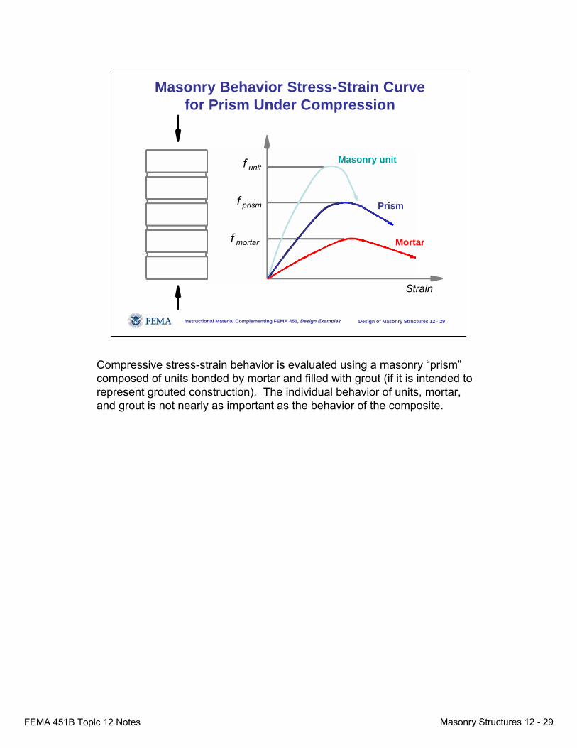
Masonry Behavior Stress-Strain Curve for Prism Under Compression
Masonry unit
Prism
Mortar
Strain
f unit
f prism
f mortar
Compressive stress-strain behavior is evaluated using a masonry “prism”composed of units bonded by mortar and filled with grout (if it is intended to represent grouted construction). The individual behavior of units, mortar, and grout is not nearly as important as the behavior of the composite.
FEMA 451B Topic 12 Notes Masonry Structures 12 - 30
Instructional Material Complementing FEMA 451, Design Examples Design of Masonry Structures 12 - 30
Review Masonry Basics● Basic terms● Units● Mortar● Grout● Accessory materials
– Reinforcement (may or may not be present)– Connectors– Flashing– Sealants
● Typical details
Let’s start by reviewing masonry basics. Masonry is made up of units, mortar, grout, and accessory materials. The mortar holds the units together as well as apart, compensating for their dimensional tolerances. The grout is a fluid concrete mixture used to fill voids in the masonry and to anchor deformed reinforcement.

FEMA 451B Topic 12 Notes Masonry Structures 12 - 31
Instructional Material Complementing FEMA 451, Design Examples Design of Masonry Structures 12 - 31
Basic Terms
● Bond patterns (looking at wall):
Running bond Stack bond
1/3 Running bond Flemish bond
Bedjoints
Headjoints
Masonry units can be laid in different bond patterns. The most common of these is 1/2 running bond, often called simply “running bond.” Horizontal bed joints are continuous; vertical head joints alternate courses, and the head joint of one course aligns with the middle of the unit on the adjacent courses. In stack bond (referred to in the MSJC Code and Specification as “other than running bond”), the head joints are continuous between adjacent courses.
FEMA 451B Topic 12 Notes Masonry Structures 12 - 32
Instructional Material Complementing FEMA 451, Design Examples Design of Masonry Structures 12 - 32
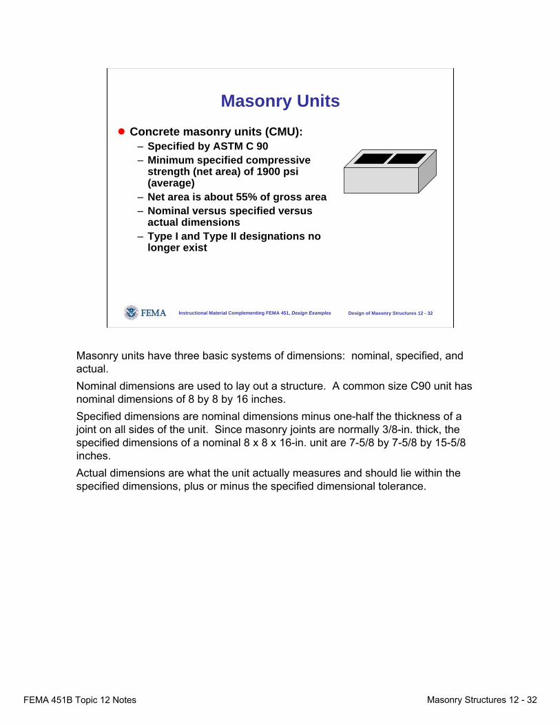
Masonry Units● Concrete masonry units (CMU):
– Specified by ASTM C 90– Minimum specified compressive
strength (net area) of 1900 psi (average)
– Net area is about 55% of gross area– Nominal versus specified versus
actual dimensions– Type I and Type II designations no
longer exist
Masonry units have three basic systems of dimensions: nominal, specified, and actual. Nominal dimensions are used to lay out a structure. A common size C90 unit has nominal dimensions of 8 by 8 by 16 inches. Specified dimensions are nominal dimensions minus one-half the thickness of a joint on all sides of the unit. Since masonry joints are normally 3/8-in. thick, the specified dimensions of a nominal 8 x 8 x 16-in. unit are 7-5/8 by 7-5/8 by 15-5/8 inches.Actual dimensions are what the unit actually measures and should lie within the specified dimensions, plus or minus the specified dimensional tolerance.
FEMA 451B Topic 12 Notes Masonry Structures 12 - 33
Instructional Material Complementing FEMA 451, Design Examples Design of Masonry Structures 12 - 33
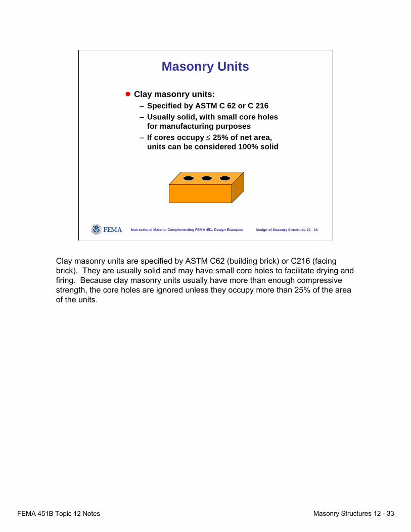
Masonry Units
● Clay masonry units:– Specified by ASTM C 62 or C 216– Usually solid, with small core holes
for manufacturing purposes– If cores occupy ≤ 25% of net area,
units can be considered 100% solid
Clay masonry units are specified by ASTM C62 (building brick) or C216 (facing brick). They are usually solid and may have small core holes to facilitate drying and firing. Because clay masonry units usually have more than enough compressive strength, the core holes are ignored unless they occupy more than 25% of the area of the units.
FEMA 451B Topic 12 Notes Masonry Structures 12 - 34
Instructional Material Complementing FEMA 451, Design Examples Design of Masonry Structures 12 - 34
Masonry Mortar
● Mortar for unit masonry is specified by ASTM C 270● Three cementitious systems
– Portland cement – lime mortar– Masonry cement mortar– Mortar cement mortar
Mortar for unit masonry is specified by ASTM C270. In specifying mortar, the designer must make three decisions:The first decision involves the cementitious system to be used. Three cementitious systems are available: portland cement-lime mortar; masonry cement mortar; and mortar cement mortar.

FEMA 451B Topic 12 Notes Masonry Structures 12 - 35
Instructional Material Complementing FEMA 451, Design Examples Design of Masonry Structures 12 - 35
Masonry Mortar
● Within each cementitious system, mortar is specified by type (M a S o N w O r K):
– Going from Type K to Type M, mortar has an increasing volume proportion of portland cement. It sets up faster and has higher compressive and tensile bond strengths.
– As the volume proportion of portland cement increases, mortar is less able to deform when hardened.
– Types N and S are specified for modern masonry construction.
Within each cementitious system, the designer must specify the mortar type. Mortar type describes the amount of cement in the mortar compared to the amount of other constituents.The designations for mortar type were intentionally selected as alternating letters in the phrase “mason work,” avoiding the connotations that might be associated with designations such as “A,” “B,” “C,” and “D.”Going from Type K to Type M, mortar has an increasing volume proportion of portland cement or other cements. It sets up faster and has higher compressive and tensile bond strengths. As the volume proportion of portland cement increases, mortar is less able to deform when hardened.Types N and S are specified for modern masonry construction.

FEMA 451B Topic 12 Notes Masonry Structures 12 - 36
Instructional Material Complementing FEMA 451, Design Examples Design of Masonry Structures 12 - 36
Masonry Mortar
● Under ASTM C270, mortar can be specified by proportion or by property.
● If mortar is specified by proportion, compliance is verified only by verifying proportions. For example:
– Type S PCL mortar has volume proportions of 1 part cement to about 0.5 parts hydrated mason’s lime to about 4.5 parts mason’s sand.
– Type N masonry cement mortar (single-bag) has one part Type N masonry cement and 3 parts mason’s sand.
Under ASTM C270, mortar can be specified by proportion or by property. The proportion specification is the default.When mortar is specified by proportion, a Type S PCL mortar has volume proportions of 1 part cement to about 0.5 parts hydrated mason’s lime to about 4.5 parts mason’s sand. A Type N masonry cement mortar (using the most common single-bag case) has one part Type N masonry cement and about 3 parts mason’s sand.Note that the amount of water is not specified. This is because the water should be adjusted by the mason in the field to achieve good workability.
FEMA 451B Topic 12 Notes Masonry Structures 12 - 37
Instructional Material Complementing FEMA 451, Design Examples Design of Masonry Structures 12 - 37
Masonry Mortar
● Under ASTM C270, mortar can be specified by proportion or by property:
– Proportion specification is simpler -- verify in the field that volume proportions meet proportion limits.
– Property specification is more complex: (1) establish the proportions necessary to produce a mortar that, tested at laboratory flow, will meet the required compressive strength, air content, and retentivity (ability to retain water) requirements and (2) verify in the field that volume proportions meet proportion limits.
“Flow” is a standard ASTM measurement of the workability of a mortar. Mortar in the field typically has a flow of 130 to 135. ASTM specifications have no requirements for the properties of mortar mixed to field flow. ASTM property specifications are based on mortar with a so-called “laboratory flow” of 110 representing the characteristics of mortar after some of the water has been absorbed from it by the surrounding units.To specify mortar by proportion according to ASTM C270 is relatively simple. The required proportions are given in the specification, and compliance is verified by verifying that the mortar is being batched using those proportions.To specify mortar by property according to ASTM C270, one must evaluate, at laboratory flow of 110, the compressive strength, air content, and retentivity of different mortars and then decide on volume proportions that will meet the required criteria. Finally, one must verify in the field that the mortar s being batched using those proportions.
FEMA 451B Topic 12 Notes Masonry Structures 12 - 38
Instructional Material Complementing FEMA 451, Design Examples Design of Masonry Structures 12 - 38
Masonry Mortar
● The proportion specification is the default. Unless the property specification is used, no mortar testing is necessary.
● The proportion of water is not specified. It is determined by the mason to achieve good productivity and workmanship.
● Masonry units absorb water from the mortar decreasing its water-cement ratio and increasing its compressive strength. Mortar need not have high compressive strength.
The proportion specification is the default. Unless the property specification is used, no mortar testing is necessary.Some suggest that the words “by proportion” be added to the end of specifications to emphasize that compliance with proportion specifications involves no testing whatsoever.The proportion of water is not specified. It is determined by the mason to achieve good productivity and workmanship.Masonry units absorb water from the mortar decreasing its water-cement ratio and increasing its compressive strength. Mortar need not have high compressive strength.
FEMA 451B Topic 12 Notes Masonry Structures 12 - 39
Instructional Material Complementing FEMA 451, Design Examples Design of Masonry Structures 12 - 39
Grout
● Grout for unit masonry is specified by ASTM C 476● Two kinds of grout:
– Fine grout (cement, sand, water)– Coarse grout (cement, sand, pea gravel, water)
● ASTM C 476 permits a small amount of hydrated lime, but does not require any. Lime is usually not used in plant – batched grout.
Grout for unit masonry is specified by ASTM C 476, which addresses two kinds of grout: fine grout which is composed of cement, sand and water and coarse grout, which is composed of cement, sand, pea gravel and water. The fairly common practice of specifying grout as concrete is acceptable but only if the resulting mixture proportion conforms to C476.ASTM C 476 permits a small amount of hydrated lime but does not require any. Lime is usually not used in plant-batched grout because lime is not available in such plants.
FEMA 451B Topic 12 Notes Masonry Structures 12 - 40
Instructional Material Complementing FEMA 451, Design Examples Design of Masonry Structures 12 - 40
Grout
● Under ASTM C476, grout can be specified by proportion or by compressive strength:
– Proportion specification is simpler. It requires only that volume proportions of ingredients be verified.
– Specification by compressive strength is more complex. It requires compression testing of grout in a permeable mold (ASTM C 1019).
Under ASTM C476, grout can be specified by proportion or by compressive strength.The proportion specification is simpler. It requires only that volume proportions of ingredients be verified.Specification by compressive strength is more complex. It requires compression testing of grout in a permeable mold (ASTM C 1019).
FEMA 451B Topic 12 Notes Masonry Structures 12 - 41
Instructional Material Complementing FEMA 451, Design Examples Design of Masonry Structures 12 - 41
Grout
● If grout is specified by proportion, compliance is verified only by verifying proportions. For example:
– Fine grout has volume proportions of 1 part cement to about 3 parts mason’s sand.
– Coarse grout has volume proportions of 1 part cement to about 3 parts mason’s sand and about 2 parts pea gravel.
● Unless the compressive-strength specification is used, no grout testing is necessary.
If grout is specified by proportion, compliance is verified only by verifying proportions. For example, fine grout has volume proportions of 1 part cement to about 3 parts mason’s sand. Coarse grout has volume proportions of 1 part cement to about 3 parts mason’s sand and about 2 parts pea gravel.Unless the compressive-strength specification is used, no grout testing is necessary.

FEMA 451B Topic 12 Notes Masonry Structures 12 - 42
Instructional Material Complementing FEMA 451, Design Examples Design of Masonry Structures 12 - 42
Grout
● The proportion of water is not specified. The slump should be 8 to 11 in.
● Masonry units absorb water from the grout decreasing its water-cement ratio and increasing its compressive strength. High-slump grout will still be strong enough.
The proportion of water in grout is not specified. The slump should be 8 to 11 inches.Masonry units absorb water from the grout, decreasing its water-cement ratio and increasing its compressive strength. High-slump grout will still be strong enough.

FEMA 451B Topic 12 Notes Masonry Structures 12 - 43
Instructional Material Complementing FEMA 451, Design Examples Design of Masonry Structures 12 - 43
Accessory Materials
Horizontally oriented expansion joint under shelf angle:
Weepholes
Shelf angle
Flashing
Sealant gap~ 3 / 8 in.
One of the most important details in a masonry building is the expansion joint under shelf angles in clay masonry veneer. Clay masonry expands over time; concrete and concrete masonry shrink. If the veneer is laid without the expansion joint, it will end up supporting the building even though it is not made to resist the resulting compression.
FEMA 451B Topic 12 Notes Masonry Structures 12 - 44
Instructional Material Complementing FEMA 451, Design Examples Design of Masonry Structures 12 - 44
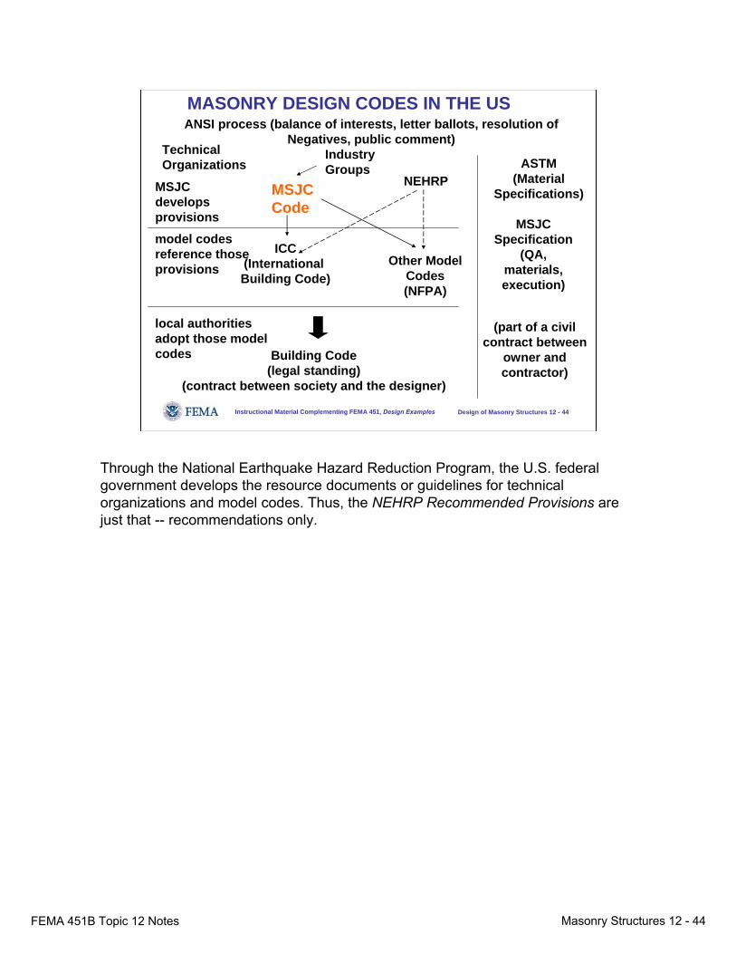
MASONRY DESIGN CODES IN THE US
Technical Organizations
MSJCCode
Other Model Codes(NFPA)
Building Code(legal standing)
(contract between society and the designer)
local authorities adopt those model codes
ICC(International Building Code)
NEHRPASTM
(Material Specifications)
(part of a civil contract between
owner and contractor)
ANSI process (balance of interests, letter ballots, resolution of Negatives, public comment)
IndustryGroups
MSJC Specification
(QA, materials, execution)
model codes reference those provisions
MSJC develops provisions
Through the National Earthquake Hazard Reduction Program, the U.S. federal government develops the resource documents or guidelines for technical organizations and model codes. Thus, the NEHRP Recommended Provisions are just that -- recommendations only.

FEMA 451B Topic 12 Notes Masonry Structures 12 - 45
Instructional Material Complementing FEMA 451, Design Examples Design of Masonry Structures 12 - 45
What is the MSJC Code and Specification... ?
2005 MSJCCode and
Specification
ASCE(ASCE 5-05)(ASCE 6-05)
TMS(TMS 402-05)(TMS 602-05)
ACI(ACI 530-05)
(ACI 530.1-05)
“Masonry Standards Joint Committee”
The 2003 NEHRP Recommended Provisions reference the MSJC Code and Specification. That document is developed under ANSI-consensus rules by the Masonry Standards Joint Committee, which is sponsored jointly by The Masonry Society, The American Concrete Institute, and The American Society of Civil Engineers. The latest version is the 2005 edition.
FEMA 451B Topic 12 Notes Masonry Structures 12 - 46
Instructional Material Complementing FEMA 451, Design Examples Design of Masonry Structures 12 - 46
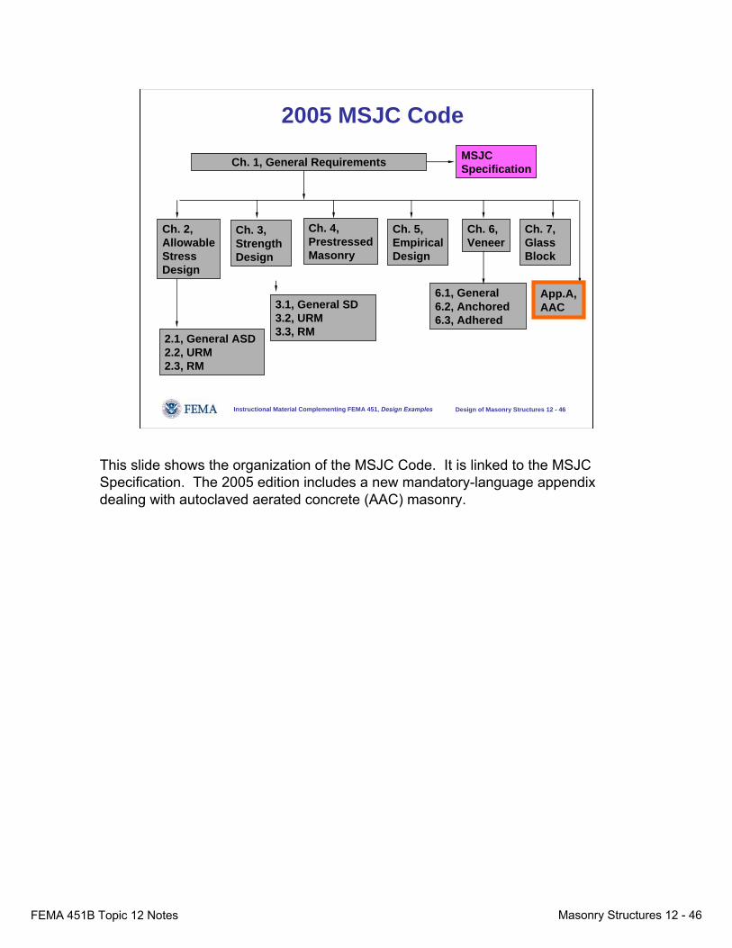
2005 MSJC Code
Ch. 1, General Requirements
Ch. 2,AllowableStressDesign
Ch. 3, Strength Design
Ch. 4,PrestressedMasonry
Ch. 5,EmpiricalDesign
Ch. 6,Veneer
Ch. 7,Glass Block
2.1, General ASD 2.2, URM2.3, RM
6.1, General6.2, Anchored6.3, Adhered
3.1, General SD 3.2, URM3.3, RM
MSJCSpecification
App.A, AAC
This slide shows the organization of the MSJC Code. It is linked to the MSJC Specification. The 2005 edition includes a new mandatory-language appendix dealing with autoclaved aerated concrete (AAC) masonry.
FEMA 451B Topic 12 Notes Masonry Structures 12 - 47
Instructional Material Complementing FEMA 451, Design Examples Design of Masonry Structures 12 - 47
Relation Between Code and Specification
● Code:– Design provisions are given in Chapters 1-7 and
Appendix A– Sections 1.2.4 and 1.14 require a QA program in
accordance with the specification– Section 1.4 invokes the specification by reference.
● Specification:– Verify compliance with specified fm′– Comply with required level of quality assurance– Comply with specified products and execution
The MSJC Code references and is intended to be used with the MSJC Specification.In the Code, design provisions are given in Chapters 1 through 7 and Appendix A. Sections 1.2.4 and 1.14 require a QA program in accordance with the Specification. Section 1.4 invokes the Specification by reference.The Specifications requires verification of compliance with specified fm′; compliance with the required level of quality assurance; and compliance with the specified products and execution.
FEMA 451B Topic 12 Notes Masonry Structures 12 - 48
Instructional Material Complementing FEMA 451, Design Examples Design of Masonry Structures 12 - 48
Role of fm′● Concrete:
– Designer states assumed value of fc′– Compliance is verified by compression tests on
cylinders cast in the field and cured under ideal conditions
● Masonry– Designer states assumed value of fm′– Compliance is verified by “unit strength method” or
by “prism test method”
In designing and specifying masonry according to the MSJC Code, the role of f’m is analogous to that of f’c for concrete.For concrete, the designer states an assumed value of fc′ and compliance is verified by compression tests on cylinders cast in the field and cured under ideal conditions.For masonry, the designer states an assumed value of fm′ and compliance is verified either by the “unit strength method,” or by the “prism test method.”
FEMA 451B Topic 12 Notes Masonry Structures 12 - 49
Instructional Material Complementing FEMA 451, Design Examples Design of Masonry Structures 12 - 49
Verify Compliance with Specified fm′
● Unit strength method (Spec 1.4 B 2):– Compressive strengths from unit manufacturer– ASTM C 270 mortar– Grout meeting ASTM C 476 or 2,000 psi
● Prism test method (Spec 1.4 B 3):– Pro -- can permit optimization of materials– Con -- require testing, qualified testing lab, and
procedures in case of non-complying results
The MSJC Code offers two ways of demonstrating compliance with the specified f’m. The simplest is the “unit strength method.” Using compressive strengths for standard ASTM units obtained by the unit manufacturer as part of production quality control, mortar meeting ASTM C270 and grout meeting ASTM C476 or having a compressive strength of at least 2000 psi, conservative values for f’m can be taken from Tables 1 and 2 of the Specification. Alternatively, prisms can be constructed and tested by ASTM C1314.
FEMA 451B Topic 12 Notes Masonry Structures 12 - 50
Instructional Material Complementing FEMA 451, Design Examples Design of Masonry Structures 12 - 50
Example of Unit Strength Method (Specification Tables 1, 2)
● Clay masonry units (Table 1):– Unit compressive strength ≥ 4150 psi– Type N mortar– Prism strength can be taken as 1500 psi
● Concrete masonry units (Table 2):– Unit compressive strength ≥ 1900 psi– Type S mortar– Prism strength can be taken as 1500 psi
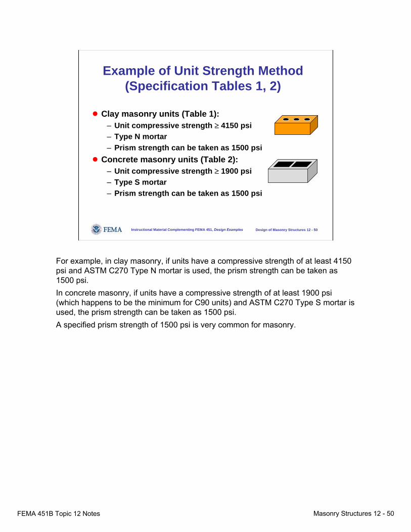
For example, in clay masonry, if units have a compressive strength of at least 4150 psi and ASTM C270 Type N mortar is used, the prism strength can be taken as 1500 psi.In concrete masonry, if units have a compressive strength of at least 1900 psi (which happens to be the minimum for C90 units) and ASTM C270 Type S mortar is used, the prism strength can be taken as 1500 psi.A specified prism strength of 1500 psi is very common for masonry.
FEMA 451B Topic 12 Notes Masonry Structures 12 - 51
Instructional Material Complementing FEMA 451, Design Examples Design of Masonry Structures 12 - 51
Application of Unit Strength Method (Spec Tables 1, 2)
● Design determines required material specification:– Designer states assumed value of fm′– Specifier specifies units, mortar and grout that will
satisfy “unit strength method”● Compliance with fm′ can be verified with no tests on
mortar, grout, or prisms
If compliance with the specified f’m is verified by the unit strength method and compliance with ASTM C270 (mortar) and ASTM C476 (grout) is verified by proportion), no job-specific testing whatsoever is required.

FEMA 451B Topic 12 Notes Masonry Structures 12 - 52
Instructional Material Complementing FEMA 451, Design Examples Design of Masonry Structures 12 - 52
Comply with Specified Products and Execution
● Products -- Specification Article 2:– Units, mortar, grout, accessory materials
● Execution -- Specification Article 3– Inspection– Preparation– Installation of masonry, reinforcement, grout,
prestressing tendons
Finally, the MSJC Specification requires compliance with the specified products (Article 2), which means units, mortar, grout and accessory materials, and with the specified execution (Article 3), which means inspection, preparation and installation of masonry, reinforcement, grout and prestressing tendons.
FEMA 451B Topic 12 Notes Masonry Structures 12 - 53
Instructional Material Complementing FEMA 451, Design Examples Design of Masonry Structures 12 - 53
Organization of MSJC CodeChapter 1
1.1 – 1.6 Scope, contract documents and calculations, special systems, reference standards, notation, definitions
1.7 Loading1.8 Material properties1.9 Section properties1.10 Deflections
1.11 Stack bond masonry1.12 Corbels1.13 Details of reinforcement1.14 Seismic design
requirements1.15 Quality assurance program1.16 Construction
Chapter 1 of the MSJC Code is an “umbrella” chapter. It gives basic requirements that govern over the other provisions. As with other slides, the sections marked in orange are emphasized in the slides that immediately follow.
FEMA 451B Topic 12 Notes Masonry Structures 12 - 54
Instructional Material Complementing FEMA 451, Design Examples Design of Masonry Structures 12 - 54
Code 1.8, Material Properties
● Chord modulus of elasticity, shear modulus, thermal expansion coefficients, and creep coefficients for clay, concrete, and AAC masonry
● Moisture expansion coefficient for clay masonry● Shrinkage coefficients for concrete masonry
Code Section 1.8 deals with material properties to be used for design. It specifies the values of chord modulus of elasticity, shear modulus, thermal expansion coefficients, and creep coefficients for clay, concrete, and AAC masonry. It also gives moisture expansion coefficients to be used for clay masonry and shrinkage coefficients to be used for concrete masonry.
FEMA 451B Topic 12 Notes Masonry Structures 12 - 55
Instructional Material Complementing FEMA 451, Design Examples Design of Masonry Structures 12 - 55
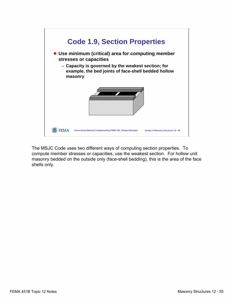
Code 1.9, Section Properties● Use minimum (critical) area for computing member
stresses or capacities– Capacity is governed by the weakest section; for
example, the bed joints of face-shell bedded hollow masonry
The MSJC Code uses two different ways of computing section properties. To compute member stresses or capacities, use the weakest section. For hollow unit masonry bedded on the outside only (face-shell bedding), this is the area of the face shells only.
FEMA 451B Topic 12 Notes Masonry Structures 12 - 56
Instructional Material Complementing FEMA 451, Design Examples Design of Masonry Structures 12 - 56
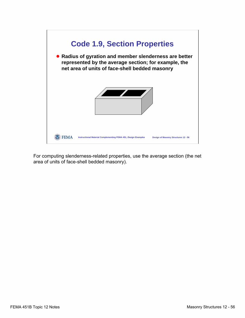
Code 1.9, Section Properties● Radius of gyration and member slenderness are better
represented by the average section; for example, the net area of units of face-shell bedded masonry
For computing slenderness-related properties, use the average section (the net area of units of face-shell bedded masonry).
FEMA 451B Topic 12 Notes Masonry Structures 12 - 57
Instructional Material Complementing FEMA 451, Design Examples Design of Masonry Structures 12 - 57
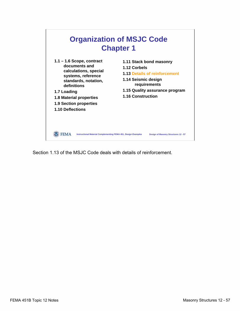
Organization of MSJC CodeChapter 1
1.1 – 1.6 Scope, contract documents and calculations, special systems, reference standards, notation, definitions
1.7 Loading1.8 Material properties1.9 Section properties1.10 Deflections
1.11 Stack bond masonry1.12 Corbels1.13 Details of reinforcement1.14 Seismic design
requirements1.15 Quality assurance program1.16 Construction
Section 1.13 of the MSJC Code deals with details of reinforcement.
FEMA 451B Topic 12 Notes Masonry Structures 12 - 58
Instructional Material Complementing FEMA 451, Design Examples Design of Masonry Structures 12 - 58
Code 1.13, Details of Reinforcement
● Reinforcing bars must be embedded in grout; joint reinforcement can be embedded in mortar
● Placement of reinforcement● Protection for reinforcement● Standard hooks
Reinforcing bars must be embedded in grout; joint reinforcement can be embedded in mortar. Minimum distances between reinforcement and the insides of cells or void spaces are specified as are minimum cover distances for protection of reinforcement from corrosion. Standard hooks are defined.
FEMA 451B Topic 12 Notes Masonry Structures 12 - 59
Instructional Material Complementing FEMA 451, Design Examples Design of Masonry Structures 12 - 59
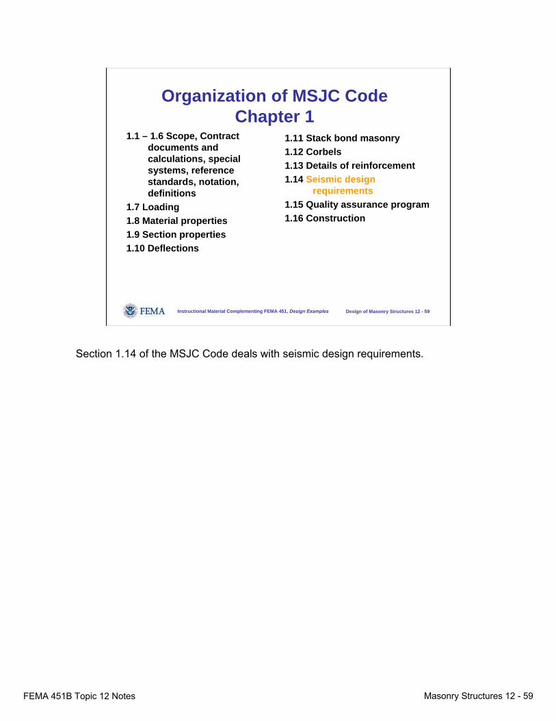
Organization of MSJC CodeChapter 1
1.1 – 1.6 Scope, Contract documents and calculations, special systems, reference standards, notation, definitions
1.7 Loading1.8 Material properties1.9 Section properties1.10 Deflections
1.11 Stack bond masonry1.12 Corbels1.13 Details of reinforcement1.14 Seismic design
requirements1.15 Quality assurance program1.16 Construction
Section 1.14 of the MSJC Code deals with seismic design requirements.
FEMA 451B Topic 12 Notes Masonry Structures 12 - 60
Instructional Material Complementing FEMA 451, Design Examples Design of Masonry Structures 12 - 60
Code 1.14, Seismic Design● Applies to all masonry except
– Glass unit masonry– Veneers
● Seeks to improve performance of masonry structures in earthquakes
– Improves ductility of masonry members– Improves connectivity of masonry members
● Different requirements for AAC masonry
Section 1.14 applies to all masonry except glass unit masonry and veneers. It seeks to improve performance of masonry structures in earthquakes by improving the ductility of masonry members and the connectivity of masonry members.Seismic requirements for autoclaved aerated concrete (AAC) masonry are somewhat different and are not addressed here.
FEMA 451B Topic 12 Notes Masonry Structures 12 - 61
Instructional Material Complementing FEMA 451, Design Examples Design of Masonry Structures 12 - 61
Code 1.14, Seismic Design
● Define a structure’s Seismic Design Category (SDC) according to ASCE 7-02
– SDC depends on seismic risk (geographic location), importance, underlying soil
● SDC determines – Required types of shear walls (prescriptive
reinforcement)– Prescriptive reinforcement for other masonry elements– Permitted design approaches for LFRS (lateral force-
resisting system)
In Code Section 1.14, the structure’s Seismic Design Category (SDC) is defined according to ASCE 7-02. The SDC depends on seismic risk (geographic location), importance, and underlying soil.The SDC determines the required types of shear walls (prescriptive reinforcement); the prescriptive reinforcement required for other masonry elements; and the permitted design approaches for LFRS (lateral force-resisting system).
FEMA 451B Topic 12 Notes Masonry Structures 12 - 62
Instructional Material Complementing FEMA 451, Design Examples Design of Masonry Structures 12 - 62
Code 1.14, Seismic Design● Seismic design requirements are keyed to ASCE 7-
02 Seismic Design Categories (from A up to F).● Requirements are cumulative; requirements in each
“higher” category are added to requirements in the previous category.
Seismic design requirements are keyed to ASCE 7-02 Seismic Design Categories (from A up to F). Requirements are cumulative; requirements in each “higher” category are added to requirements in the previous category.
FEMA 451B Topic 12 Notes Masonry Structures 12 - 63
Instructional Material Complementing FEMA 451, Design Examples Design of Masonry Structures 12 - 63
Code 1.14, Seismic Design
● Seismic Design Category A:– Drift limit = 0.007– Minimum design connection force for wall-to roof
and wall-to-floor connections● Seismic Design Category B:
– Lateral force resisting system cannot be designed empirically
In Seismic Design Category A, a drift limit of 0.007 and a minimum design connection force are imposed for wall-to-roof and wall-to-floor connections.In Seismic Design Category B, the lateral force resisting system cannot be designed empirically.
FEMA 451B Topic 12 Notes Masonry Structures 12 - 64
Instructional Material Complementing FEMA 451, Design Examples Design of Masonry Structures 12 - 64
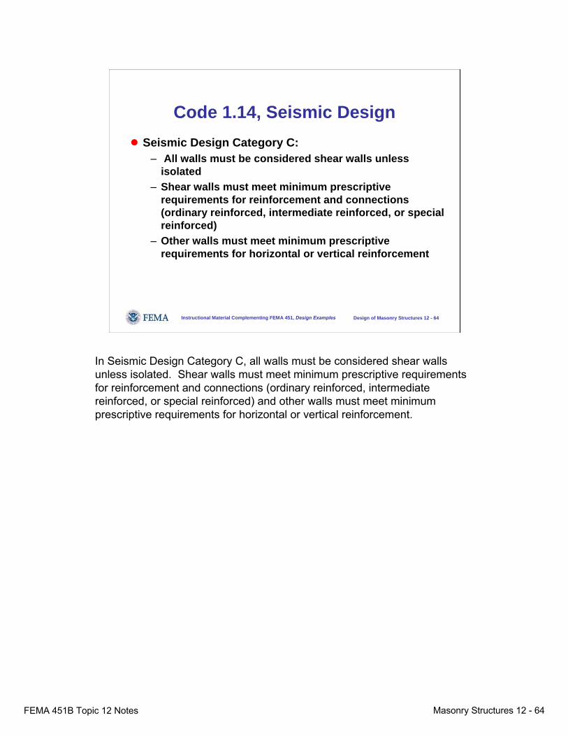
Code 1.14, Seismic Design● Seismic Design Category C:
– All walls must be considered shear walls unless isolated
– Shear walls must meet minimum prescriptive requirements for reinforcement and connections (ordinary reinforced, intermediate reinforced, or special reinforced)
– Other walls must meet minimum prescriptive requirements for horizontal or vertical reinforcement
In Seismic Design Category C, all walls must be considered shear walls unless isolated. Shear walls must meet minimum prescriptive requirements for reinforcement and connections (ordinary reinforced, intermediate reinforced, or special reinforced) and other walls must meet minimum prescriptive requirements for horizontal or vertical reinforcement.
FEMA 451B Topic 12 Notes Masonry Structures 12 - 65
Instructional Material Complementing FEMA 451, Design Examples Design of Masonry Structures 12 - 65
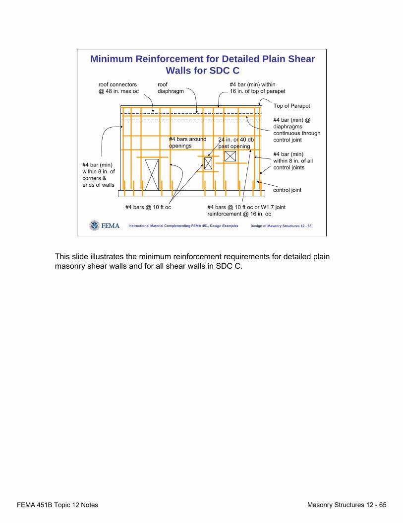
Minimum Reinforcement for Detailed Plain Shear Walls for SDC C
#4 bar (min) within 8 in. of corners & ends of walls
roofdiaphragm
roof connectors@ 48 in. max oc
#4 bar (min) within16 in. of top of parapet
Top of Parapet
#4 bar (min) @ diaphragms continuous through control joint
#4 bar (min) within 8 in. of all control joints
control joint
#4 bars @ 10 ft oc or W1.7 joint reinforcement @ 16 in. oc
#4 bars @ 10 ft oc
24 in. or 40 db past opening
#4 bars around openings
This slide illustrates the minimum reinforcement requirements for detailed plain masonry shear walls and for all shear walls in SDC C.
FEMA 451B Topic 12 Notes Masonry Structures 12 - 66
Instructional Material Complementing FEMA 451, Design Examples Design of Masonry Structures 12 - 66
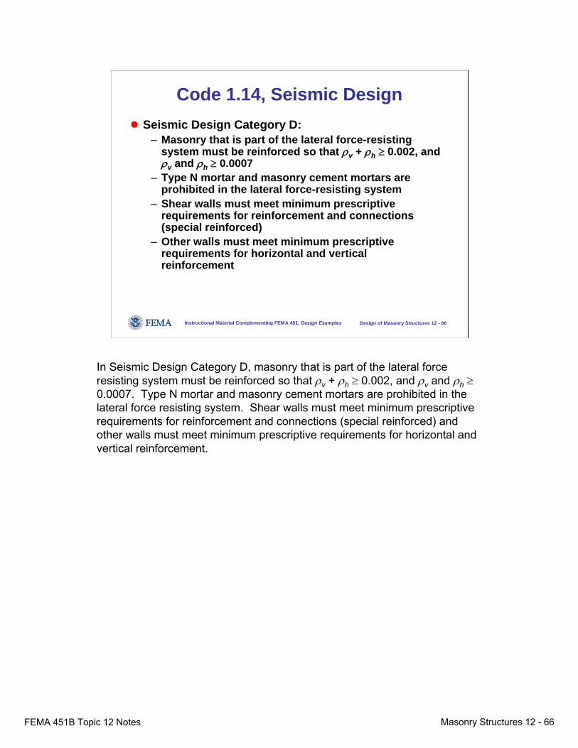
Code 1.14, Seismic Design● Seismic Design Category D:
– Masonry that is part of the lateral force-resisting system must be reinforced so that ρv + ρh ≥ 0.002, and ρv and ρh ≥ 0.0007
– Type N mortar and masonry cement mortars are prohibited in the lateral force-resisting system
– Shear walls must meet minimum prescriptive requirements for reinforcement and connections (special reinforced)
– Other walls must meet minimum prescriptive requirements for horizontal and vertical reinforcement
In Seismic Design Category D, masonry that is part of the lateral force resisting system must be reinforced so that ρv + ρh ≥ 0.002, and ρv and ρh ≥0.0007. Type N mortar and masonry cement mortars are prohibited in the lateral force resisting system. Shear walls must meet minimum prescriptive requirements for reinforcement and connections (special reinforced) and other walls must meet minimum prescriptive requirements for horizontal and vertical reinforcement.
FEMA 451B Topic 12 Notes Masonry Structures 12 - 67
Instructional Material Complementing FEMA 451, Design Examples Design of Masonry Structures 12 - 67
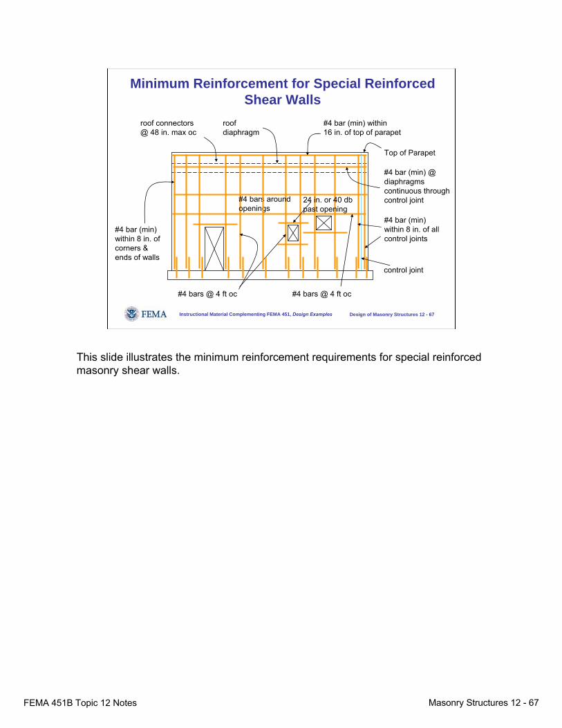
Minimum Reinforcement for Special Reinforced Shear Walls
roofdiaphragm
roof connectors@ 48 in. max oc
#4 bar (min) within16 in. of top of parapet
Top of Parapet
#4 bar (min) @ diaphragms continuous through control joint
#4 bar (min) within 8 in. of all control joints
control joint
#4 bars @ 4 ft oc#4 bars @ 4 ft oc
#4 bar (min) within 8 in. of corners & ends of walls
24 in. or 40 db past opening
#4 bars around openings
This slide illustrates the minimum reinforcement requirements for special reinforced masonry shear walls.
FEMA 451B Topic 12 Notes Masonry Structures 12 - 68
Instructional Material Complementing FEMA 451, Design Examples Design of Masonry Structures 12 - 68
Code 1.14, Seismic Design● Seismic Design Categories E and F:
– Additional reinforcement requirements for stack-bond masonry
In Seismic Design Categories E and F, additional requirements are imposed for stack-bond masonry because it is inherently weaker in flexure across continuous head joints.
FEMA 451B Topic 12 Notes Masonry Structures 12 - 69
Instructional Material Complementing FEMA 451, Design Examples Design of Masonry Structures 12 - 69
Minimum Reinforcement, SW Types
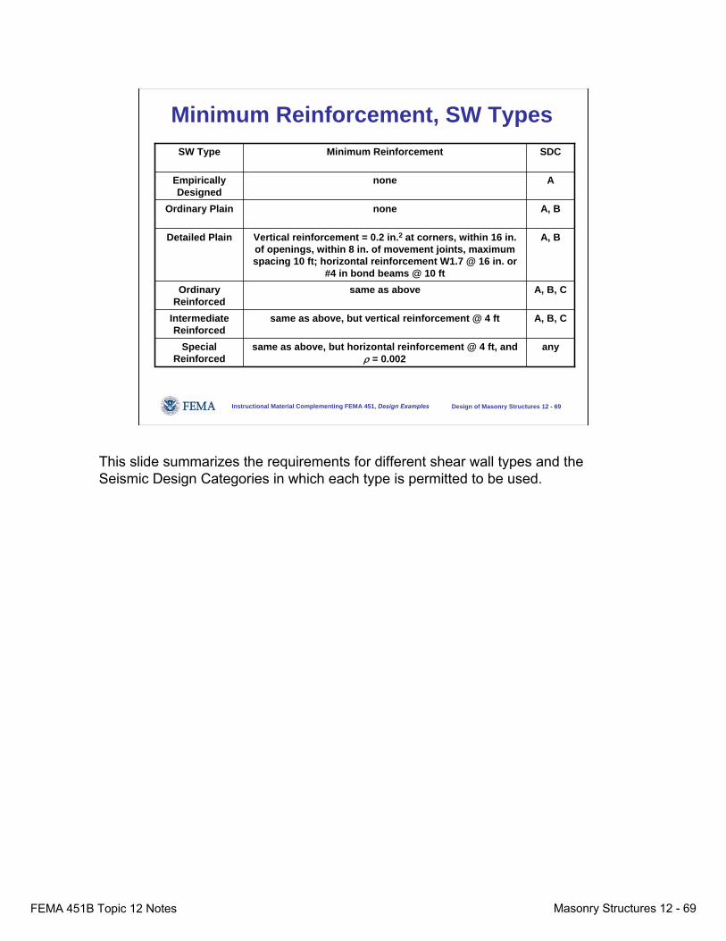
anysame as above, but horizontal reinforcement @ 4 ft, and ρ = 0.002
Special Reinforced
A, B, Csame as above, but vertical reinforcement @ 4 ftIntermediate Reinforced
A, B, Csame as aboveOrdinary Reinforced
A, BVertical reinforcement = 0.2 in.2 at corners, within 16 in. of openings, within 8 in. of movement joints, maximum spacing 10 ft; horizontal reinforcement W1.7 @ 16 in. or
#4 in bond beams @ 10 ft
Detailed Plain
A, BnoneOrdinary Plain
AnoneEmpirically Designed
SDCMinimum ReinforcementSW Type
This slide summarizes the requirements for different shear wall types and the Seismic Design Categories in which each type is permitted to be used.
FEMA 451B Topic 12 Notes Masonry Structures 12 - 70
Instructional Material Complementing FEMA 451, Design Examples Design of Masonry Structures 12 - 70
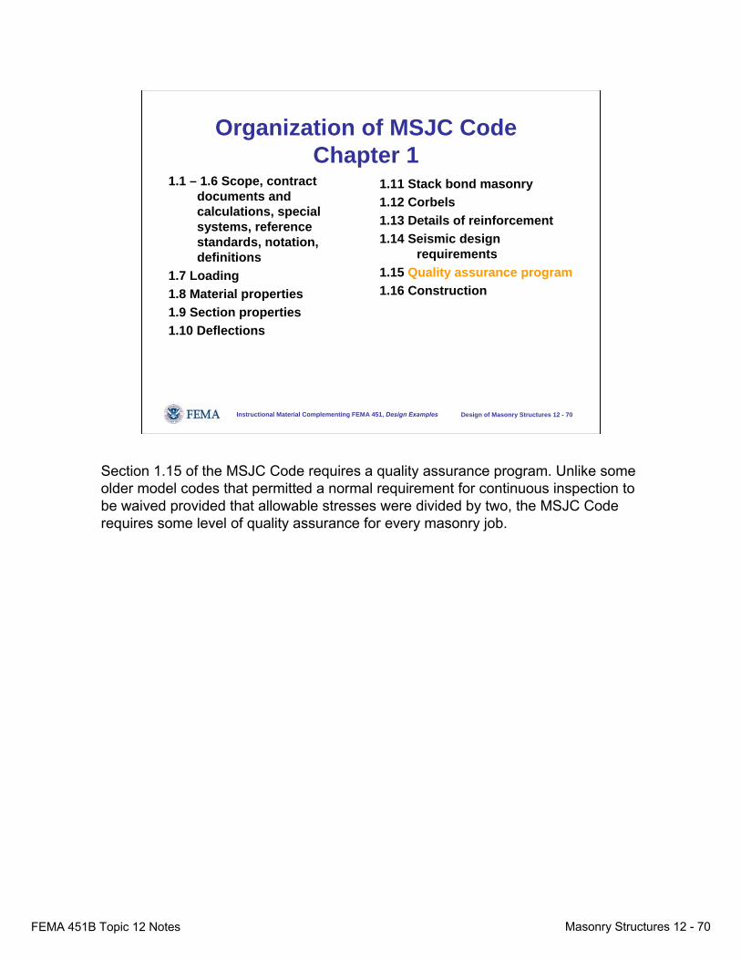
Organization of MSJC CodeChapter 1
1.1 – 1.6 Scope, contract documents and calculations, special systems, reference standards, notation, definitions
1.7 Loading1.8 Material properties1.9 Section properties1.10 Deflections
1.11 Stack bond masonry1.12 Corbels1.13 Details of reinforcement1.14 Seismic design
requirements1.15 Quality assurance program1.16 Construction
Section 1.15 of the MSJC Code requires a quality assurance program. Unlike some older model codes that permitted a normal requirement for continuous inspection to be waived provided that allowable stresses were divided by two, the MSJC Code requires some level of quality assurance for every masonry job.
FEMA 451B Topic 12 Notes Masonry Structures 12 - 71
Instructional Material Complementing FEMA 451, Design Examples Design of Masonry Structures 12 - 71
Code 1.15, Quality Assurance● Requires a quality assurance program in accordance
with the MSJC Specification:– Three levels of quality assurance (A, B, C)– Compliance with specified fm′– Increasing levels of quality assurance require
increasingly strict requirements for inspection, and for compliance with specified products and execution
Section 1.15 of the MSJC Code requires a quality assurance program in accordance with the Specification. The section contemplates three levels of quality assurance (A, B, C): compliance with specified fm′, increasing levels of quality assurance with increasingly strict requirements for inspection, and for compliance with specified products and execution.
FEMA 451B Topic 12 Notes Masonry Structures 12 - 72
Instructional Material Complementing FEMA 451, Design Examples Design of Masonry Structures 12 - 72
Code 1.15, Quality Assurance
● Minimum requirements for inspection, tests, and submittals:
– Empirically designed masonry, veneers, or glass unit masonry
• Table 1.14.1.1 for nonessential facilities• Table 1.14.1.2 for essential facilities
– Other masonry• Table 1.14.1.2 for nonessential facilities • Table 1.14.1.3 for essential facilities
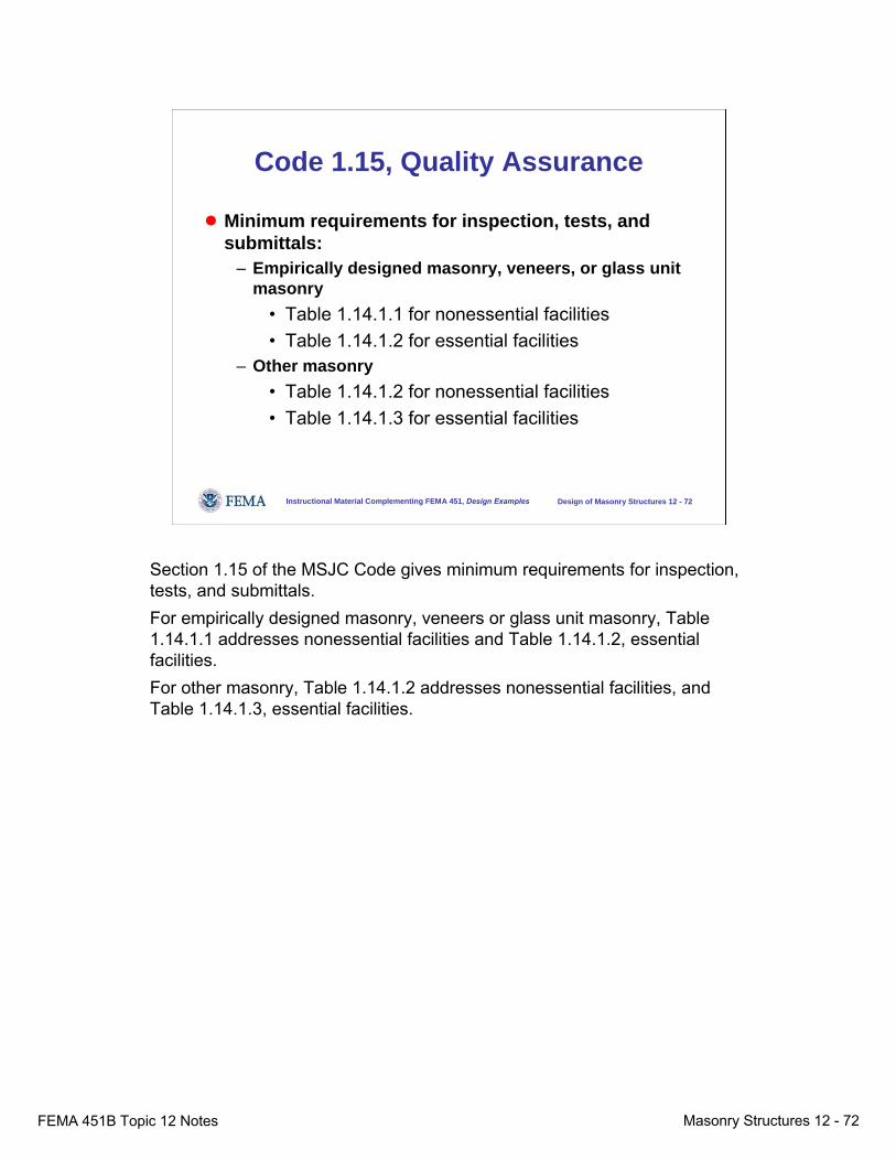
Section 1.15 of the MSJC Code gives minimum requirements for inspection, tests, and submittals. For empirically designed masonry, veneers or glass unit masonry, Table 1.14.1.1 addresses nonessential facilities and Table 1.14.1.2, essential facilities. For other masonry, Table 1.14.1.2 addresses nonessential facilities, and Table 1.14.1.3, essential facilities.
FEMA 451B Topic 12 Notes Masonry Structures 12 - 73
Instructional Material Complementing FEMA 451, Design Examples Design of Masonry Structures 12 - 73
Organization of MSJC CodeChapter 1
1.1 – 1.6 Scope, contract documents and calculations, special systems, reference standards, notation, definitions
1.7 Loading1.8 Material properties1.9 Section properties1.10 Deflections
1.11 Stack bond masonry1.12 Corbels1.13 Details of reinforcement1.14 Seismic design
requirements1.15 Quality assurance program1.16 Construction
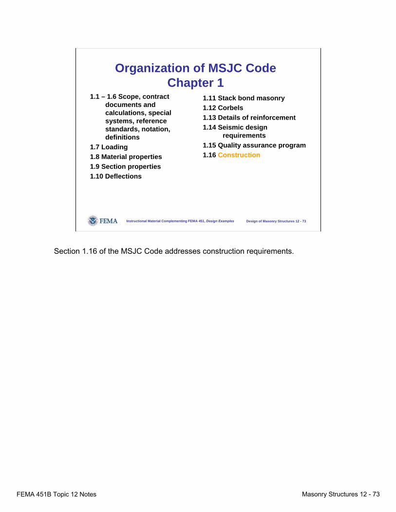
Section 1.16 of the MSJC Code addresses construction requirements.

FEMA 451B Topic 12 Notes Masonry Structures 12 - 74
Instructional Material Complementing FEMA 451, Design Examples Design of Masonry Structures 12 - 74
1.16, Construction● Minimum grout spacing (Table 1.16.2)● Embedded conduits, pipes, and sleeves:
– Consider effect of openings in design– Masonry alone resists loads
● Anchorage of masonry to structural members, frames, and other construction:
– Show type, size, and location of connectors on drawings
That section specifies a minimum grout spacing (Table 1.16.2).With respect to embedded conduits, pipes and sleeves, it requires that the effects of openings be considered in design and that masonry alone be considered effective in resisting loads.With respect to anchorage of masonry to structural members, frames and other construction, it requires that the type, size, and location of connectors be shown on drawings.
FEMA 451B Topic 12 Notes Masonry Structures 12 - 75
Instructional Material Complementing FEMA 451, Design Examples Design of Masonry Structures 12 - 75
... Organization of MSJC CodeChapter 3, Strength Design (SD)
● Fundamental basis● Loading combinations● Design strength● Deformation requirements● Ф-factors● Anchor bolts
● Bearing strength● Compressive strength● Modulus of rupture● Strength of reinforcement● Unreinforced masonry● Reinforced masonry
Now let’s move to Chapter 3 of the MSJC Code dealing with strength design. It is this chapter that first addresses the fundamental basis for strength design.
FEMA 451B Topic 12 Notes Masonry Structures 12 - 76
Instructional Material Complementing FEMA 451, Design Examples Design of Masonry Structures 12 - 76
Fundamental Basis for Strength Design
● Factored design actions must not exceed nominal capacities, reduced by Ф factors
● Quotient of load factor divided by the Ф factor is analogous to safety factor of allowable-stress design, and should be comparable to that safety factor.
Factored design actions must not exceed nominal capacities, reduced by Φ-factors. The quotient of load factor divided by Φ-factor is analogous to safety factor of allowable stress design and should be comparable to that safety factor.
FEMA 451B Topic 12 Notes Masonry Structures 12 - 77
Instructional Material Complementing FEMA 451, Design Examples Design of Masonry Structures 12 - 77
Organization of MSJC CodeChapter 3, Strength Design
● Fundamental basis● Loading combinations● Design strength● Ф factors● Deformation requirements● Anchor bolts
● Bearing strength● Compressive strength● Modulus of rupture● Strength of reinforcement● Unreinforced masonry● Reinforced masonry
Chapter 3 next addresses loading combinations.
FEMA 451B Topic 12 Notes Masonry Structures 12 - 78
Instructional Material Complementing FEMA 451, Design Examples Design of Masonry Structures 12 - 78
Code 3.1.2, Loading Combinationsfor SD
● From governing building code● From ASCE 7-02
If the governing code (e.g., IBC, NFPA 5000, or a state code) specifies strength loading combinations, they must be used. If none are specified, the strength loading combinations must be taken from ASCE 7-02. From the standpoint of the NEHRP Recommended Provisions, the combinations of Provisions Chapters 5 and 6 would govern.
FEMA 451B Topic 12 Notes Masonry Structures 12 - 79
Instructional Material Complementing FEMA 451, Design Examples Design of Masonry Structures 12 - 79
Organization of MSJC CodeChapter 3
● Fundamental basis● Loading combinations● Design strength● Ф factors● Deformation requirements● Anchor bolts
● Bearing strength● Compressive strength● Modulus of rupture● Strength of reinforcement● Unreinforced masonry● Reinforced masonry
Chapter 3 of the MSJC Code now addresses design strength.
FEMA 451B Topic 12 Notes Masonry Structures 12 - 80
Instructional Material Complementing FEMA 451, Design Examples Design of Masonry Structures 12 - 80
Code 3.1.3, Design Strength for SD
● Design strength must exceed required strength● Extra caution against brittle shear failure:
– Design shear strength shall exceed the shear corresponding to the development of 1.25 times the nominal flexural strength
– Nominal shear strength need not exceed 2.5 times required shear strength
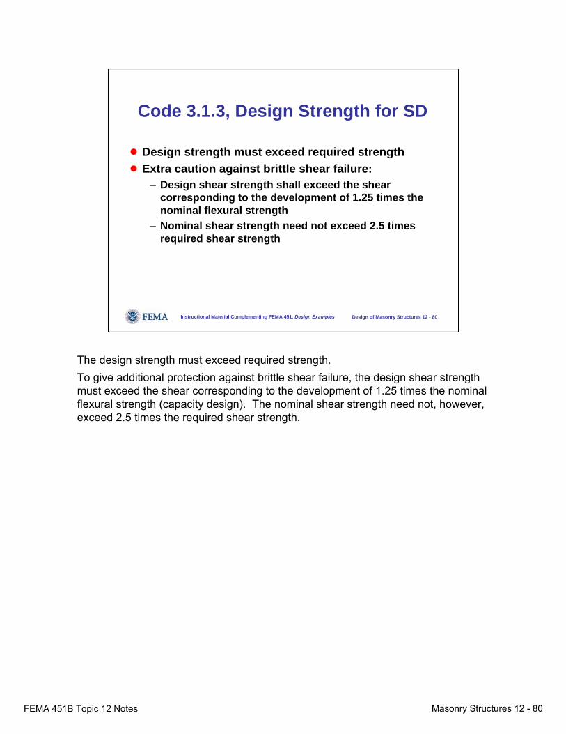
The design strength must exceed required strength. To give additional protection against brittle shear failure, the design shear strength must exceed the shear corresponding to the development of 1.25 times the nominal flexural strength (capacity design). The nominal shear strength need not, however, exceed 2.5 times the required shear strength.
FEMA 451B Topic 12 Notes Masonry Structures 12 - 81
Instructional Material Complementing FEMA 451, Design Examples Design of Masonry Structures 12 - 81
Organization of MSJC CodeChapter 3
● Fundamental basis● Loading combinations● Design strength● Ф factors● Deformation requirements● Anchor bolts
● Bearing strength● Compressive strength● Modulus of rupture● Strength of reinforcement● Unreinforced masonry● Reinforced masonry
Chapter 3 of the MSJC Code now address φ factors (capacity reduction factors).

FEMA 451B Topic 12 Notes Masonry Structures 12 - 82
Instructional Material Complementing FEMA 451, Design Examples Design of Masonry Structures 12 - 82
Code 3.1.4, Strength-reduction Factors for SD
0.600.60Bearing
---0.80Anchorage and splices of
Reinforcement
0.800.80Shear
0.600.90Combinations of flexure and axial
load
Unreinforced Masonry
Reinforced MasonryAction
The table of this slide summarizes the capacity reduction factors used by the MSJC Code. For reinforced masonry, they are quite similar to those of ACI 318.
FEMA 451B Topic 12 Notes Masonry Structures 12 - 83
Instructional Material Complementing FEMA 451, Design Examples Design of Masonry Structures 12 - 83
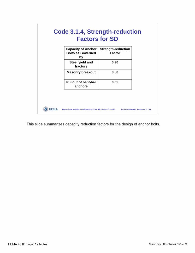
Code 3.1.4, Strength-reduction Factors for SD
0.65Pullout of bent-bar anchors
0.50Masonry breakout
0.90Steel yield and fracture
Strength-reduction Factor
Capacity of Anchor Bolts as Governed
by
This slide summarizes capacity reduction factors for the design of anchor bolts.
FEMA 451B Topic 12 Notes Masonry Structures 12 - 84
Instructional Material Complementing FEMA 451, Design Examples Design of Masonry Structures 12 - 84
Organization of MSJC CodeChapter 3
● Fundamental basis● Loading combinations● Design strength● Ф factors● Deformation requirements● Anchor bolts
● Bearing strength● Compressive strength● Modulus of rupture● Strength of reinforcement● Unreinforced masonry● Reinforced masonry
Chapter 3 of the MSJC Code now addresses deformation requirements.
FEMA 451B Topic 12 Notes Masonry Structures 12 - 85
Instructional Material Complementing FEMA 451, Design Examples Design of Masonry Structures 12 - 85
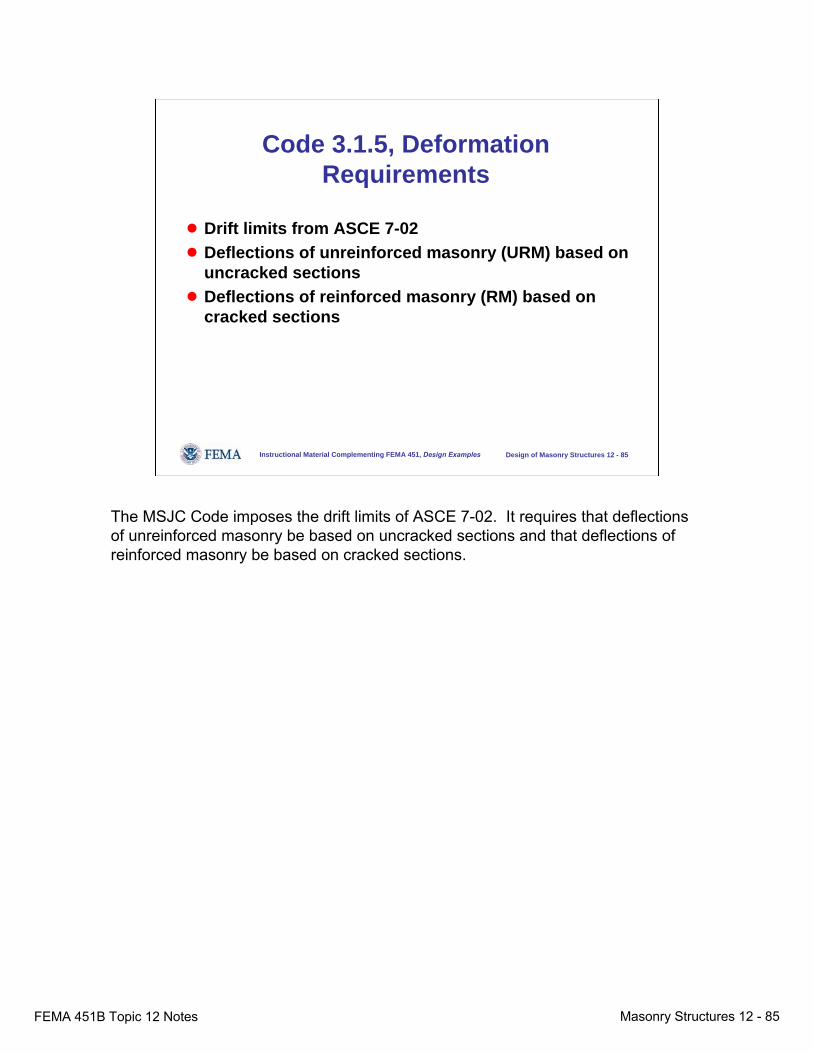
Code 3.1.5, Deformation Requirements
● Drift limits from ASCE 7-02● Deflections of unreinforced masonry (URM) based on
uncracked sections● Deflections of reinforced masonry (RM) based on
cracked sections
The MSJC Code imposes the drift limits of ASCE 7-02. It requires that deflections of unreinforced masonry be based on uncracked sections and that deflections of reinforced masonry be based on cracked sections.
FEMA 451B Topic 12 Notes Masonry Structures 12 - 86
Instructional Material Complementing FEMA 451, Design Examples Design of Masonry Structures 12 - 86
Organization of MSJC CodeChapter 3
● Fundamental basis● Loading combinations● Design strength● Ф factors● Deformation requirements● Anchor bolts
● Bearing strength● Compressive strength● Modulus of rupture● Strength of reinforcement● Unreinforced masonry● Reinforced masonry
Chapter 3 of the MSJC Code now address anchor bolts.

FEMA 451B Topic 12 Notes Masonry Structures 12 - 87
Instructional Material Complementing FEMA 451, Design Examples Design of Masonry Structures 12 - 87
Code 3.1.6, Anchor Bolts● Tensile capacity governed by:
– Tensile breakout– Yield of anchor in tension– Tensile pullout (bent-bar anchor bolts only)
● Shear capacity governed by:– Shear breakout– Yield of anchor in shear
● For combined tension and shear, use linear interaction
Tensile capacity is governed by tensile breakout, by yield of the anchor in tension, and by tensile pullout (for bent-bar anchor bolts only).Shear capacity is governed by shear breakout and by yield of the anchor in shear.Combined tension and shear are conservatively handled using a linear interaction relationship.
FEMA 451B Topic 12 Notes Masonry Structures 12 - 88
Instructional Material Complementing FEMA 451, Design Examples Design of Masonry Structures 12 - 88
Organization of MSJC CodeChapter 3
● Fundamental basis● Loading combinations● Design strength● Deformation requirements● Ф factors● Anchor bolts
● Bearing strength● Compressive strength● Modulus of rupture● Strength of reinforcement● Reinforced masonry● Unreinforced masonry
Chapter 3 of the MSJC Code now addresses required compressive strength.
FEMA 451B Topic 12 Notes Masonry Structures 12 - 89
Instructional Material Complementing FEMA 451, Design Examples Design of Masonry Structures 12 - 89
Code 3.1.7.1.1, Compressive Strength of Masonry
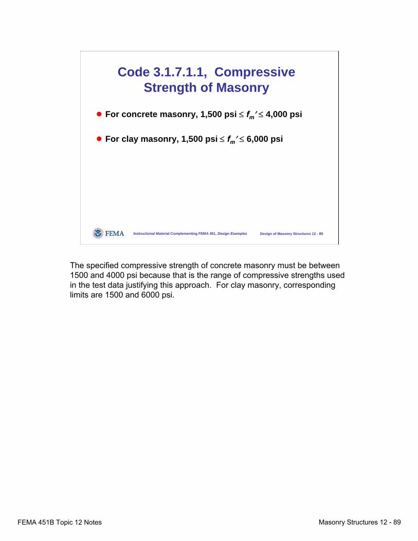
● For concrete masonry, 1,500 psi ≤ fm′ ≤ 4,000 psi
● For clay masonry, 1,500 psi ≤ fm′ ≤ 6,000 psi
The specified compressive strength of concrete masonry must be between 1500 and 4000 psi because that is the range of compressive strengths used in the test data justifying this approach. For clay masonry, corresponding limits are 1500 and 6000 psi.

FEMA 451B Topic 12 Notes Masonry Structures 12 - 90
Instructional Material Complementing FEMA 451, Design Examples Design of Masonry Structures 12 - 90
Code 3.1.7.1.2, Compressive Strength of Grout
● For concrete masonry, fm′ ≤ fg′ ≤ 5,000 psi
● For clay masonry, fg′ ≤ 6,000 psi
For similar reasons, the specified compressive strength of grout for concrete masonry is required to be between f’m and 5000 psi and for clay masonry, to be less than 6000 psi.If grout is specified by proportion, it will automatically lie within these limits.

FEMA 451B Topic 12 Notes Masonry Structures 12 - 91
Instructional Material Complementing FEMA 451, Design Examples Design of Masonry Structures 12 - 91
Organization of MSJC CodeChapter 3
● Fundamental basis● Loading combinations● Design strength● Deformation requirements● Ф factors● Anchor bolts
● Bearing strength● Compressive strength● Modulus of rupture● Strength of reinforcement● Unreinforced masonry● Reinforced masonry
Chapter 3 of the MSJC Code now addresses the modulus of rupture of masonry. For reinforced masonry, this is irrelevant for computing capacity but still relevant in computing effective moments of inertia for deflection calculations.

FEMA 451B Topic 12 Notes Masonry Structures 12 - 92
Instructional Material Complementing FEMA 451, Design Examples Design of Masonry Structures 12 - 92
Code 3.1.8.2, Modulus of Rupture
● In-plane and out-of-plane bending– Table 3.1.8.2.1– Lower values for masonry cement and air-
entrained portland cement-lime mortar– Higher values for grouted masonry– For grouted stack-bond masonry, fr = 250 psi
parallel to bed joints for continuous horizontal grout section
In contrast to earlier versions of the MSJC Code, the 2005 edition specifies identical values of the modulus of rupture for in-plane and out-of-plane bending (Table 3.1.8.2.1). Modulus of rupture values are lower for masonry cement and air-entrained portland cement-lime mortar and are higher for grouted masonry. For grouted stack-bond masonry, fr = 250 psi parallel to bed joints.
FEMA 451B Topic 12 Notes Masonry Structures 12 - 93
Instructional Material Complementing FEMA 451, Design Examples Design of Masonry Structures 12 - 93
Organization of MSJC CodeChapter 3
● Fundamental basis● Loading combinations● Design strength● Deformation requirements● Ф factors● Anchor bolts
● Bearing strength● Compressive strength● Modulus of rupture● Strength of reinforcement● Unreinforced masonry● Reinforced masonry
Chapter 3 of the MSJC Code now addresses the strength of reinforcement.
FEMA 451B Topic 12 Notes Masonry Structures 12 - 94
Instructional Material Complementing FEMA 451, Design Examples Design of Masonry Structures 12 - 94
Code 3.1.8.3, Strength of Reinforcement
● fy ≤ 60 ksi● Actual yield strength shall not exceed 1.3 times
the specified value● Compressive strength of reinforcement shall be
ignored unless the reinforcement is tied in compliance with Code 2.1.6.5
The specified yield strength of reinforcement is not to be taken in excess of 60 ksi. The actual yield strength is not to exceed 1.3 times the specified value (to avoid excesses of actual flexural capacity, which can lead to excessive shear demand).The compressive strength of reinforcement is to be ignored unless the reinforcement is tied in compliance with Code 2.1.6.5.
FEMA 451B Topic 12 Notes Masonry Structures 12 - 95
Instructional Material Complementing FEMA 451, Design Examples Design of Masonry Structures 12 - 95
Organization of MSJC CodeChapter 3
● Fundamental basis● Loading combinations● Design strength● Deformation requirements● Ф factors● Anchor bolts
● Bearing strength● Compressive strength● Modulus of rupture● Strength of reinforcement● Unreinforced masonry● Reinforced masonry
Reinforced masonry, in the context of the MSJC Code and Specification, is designed assuming that flexural tension is resisted entirely by flexural reinforcement.
FEMA 451B Topic 12 Notes Masonry Structures 12 - 96
Instructional Material Complementing FEMA 451, Design Examples Design of Masonry Structures 12 - 96
Code 3.3, Reinforced Masonry
● Masonry in flexural tension is cracked● Reinforcing steel is needed to resist tension● Similar to strength design of reinforced concrete
Masonry in flexural tension is considered to be cracked. Flexural tension is to be resisted entirely by reinforcing steel. Design is similar to strength design of reinforced concrete.
FEMA 451B Topic 12 Notes Masonry Structures 12 - 97
Instructional Material Complementing FEMA 451, Design Examples Design of Masonry Structures 12 - 97
Code 3.3, Reinforced Masonry
3.3.2 Design assumptions3.3.3 Reinforcement requirements and details, including
maximum steel percentage3.3.4 Design of piers, beams and columns:
– Nominal axial and flexural strength– Nominal shear strength
3.3.5 Design of walls for out-of-plane loads3.3.6 Design of walls for in-plane loads
Section 3.3 of the MSJC Code deals in detail with the assumptions underlying strength design of reinforced masonry:Section 3.3.3 addresses reinforcement requirements and details, including maximum steel percentage.Section 3.3.4 addresses design of piers, beams and columns, including nominal axial and flexural strength and nominal shear strengthSection 3.3.5 addresses design of walls for out-of-plane loads.Section 3.3.6 addresses design of walls for in-plane loads.Let’s look at each of these in more detail.
FEMA 451B Topic 12 Notes Masonry Structures 12 - 98
Instructional Material Complementing FEMA 451, Design Examples Design of Masonry Structures 12 - 98
Code 3.3.2, Design Assumptions
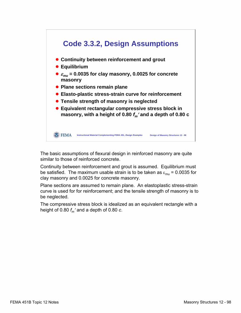
● Continuity between reinforcement and grout● Equilibrium● εmu = 0.0035 for clay masonry, 0.0025 for concrete
masonry● Plane sections remain plane● Elasto-plastic stress-strain curve for reinforcement● Tensile strength of masonry is neglected● Equivalent rectangular compressive stress block in
masonry, with a height of 0.80 fm′ and a depth of 0.80 c
The basic assumptions of flexural design in reinforced masonry are quite similar to those of reinforced concrete.Continuity between reinforcement and grout is assumed. Equilibrium must be satisfied. The maximum usable strain is to be taken as εmu = 0.0035 for clay masonry and 0.0025 for concrete masonry.Plane sections are assumed to remain plane. An elastoplastic stress-strain curve is used for for reinforcement; and the tensile strength of masonry is to be neglected.The compressive stress block is idealized as an equivalent rectangle with a height of 0.80 fm′ and a depth of 0.80 c.
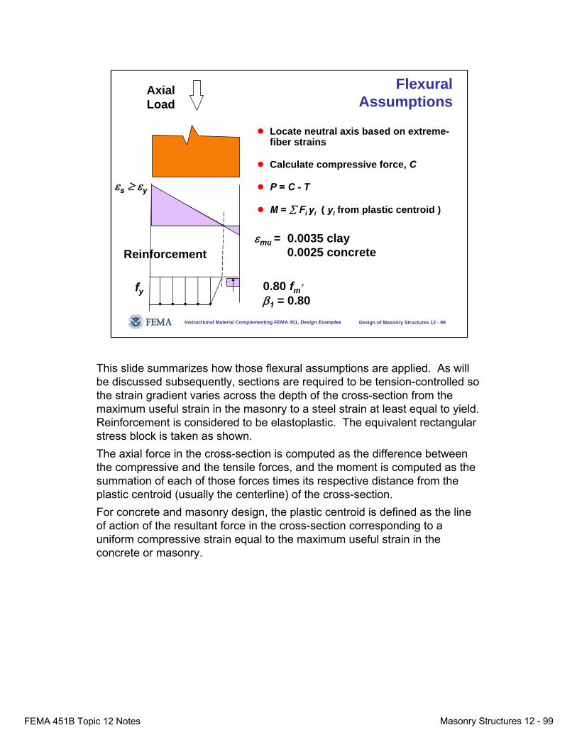
FEMA 451B Topic 12 Notes Masonry Structures 12 - 99
This slide summarizes how those flexural assumptions are applied. As will be discussed subsequently, sections are required to be tension-controlled so the strain gradient varies across the depth of the cross-section from the maximum useful strain in the masonry to a steel strain at least equal to yield. Reinforcement is considered to be elastoplastic. The equivalent rectangular stress block is taken as shown. The axial force in the cross-section is computed as the difference between the compressive and the tensile forces, and the moment is computed as the summation of each of those forces times its respective distance from the plastic centroid (usually the centerline) of the cross-section. For concrete and masonry design, the plastic centroid is defined as the line of action of the resultant force in the cross-section corresponding to a uniform compressive strain equal to the maximum useful strain in the concrete or masonry.
Instructional Material Complementing FEMA 451, Design Examples Design of Masonry Structures 12 - 99
Flexural Assumptions
● Locate neutral axis based on extreme-fiber strains
● Calculate compressive force, C
● P = C - T
● M = ∑ Fi yi ( yi from plastic centroid )
εmu = 0.0035 clay 0.0025 concrete
εs ≥ εy
fy
Reinforcement
AxialLoad
0.80 fm′β1 = 0.80

FEMA 451B Topic 12 Notes Masonry Structures 12 - 100
Instructional Material Complementing FEMA 451, Design Examples Design of Masonry Structures 12 - 100
Code 3.3.3, Reinforcement Requirements and Details
● Bar diameter ≤ 1 / 8 nominal wall thickness● Standard hooks and development length:
– Development length based on pullout and splitting● In walls, shear reinforcement must be bent around
extreme longitudinal bars● Splices:
– Lap splices based on required development length– Welded and lap splices must develop 1.25 fy
Section 3.3.3 of the MSJC Code addresses reinforcement requirements and details.The diameter of reinforcement in eighths of an inch must not exceed 1/8 the nominal wall thickness. For example, in a nominal 8-in. wall, reinforcement must not be larger in diameter than #8 (nominal diameter 8/8 inch). This is intended to prevent failure by the masonry by splitting along the bar.Standard hooks are defined. Development length is based on pullout and on splitting (bar-to-cover and bar-to-bar). In walls, shear reinforcement must be bent around extreme longitudinal bars (intended to increase the effectiveness of the hooks).Required splice length is based on required development length; welded and lap splices must develop 1.25 fy .
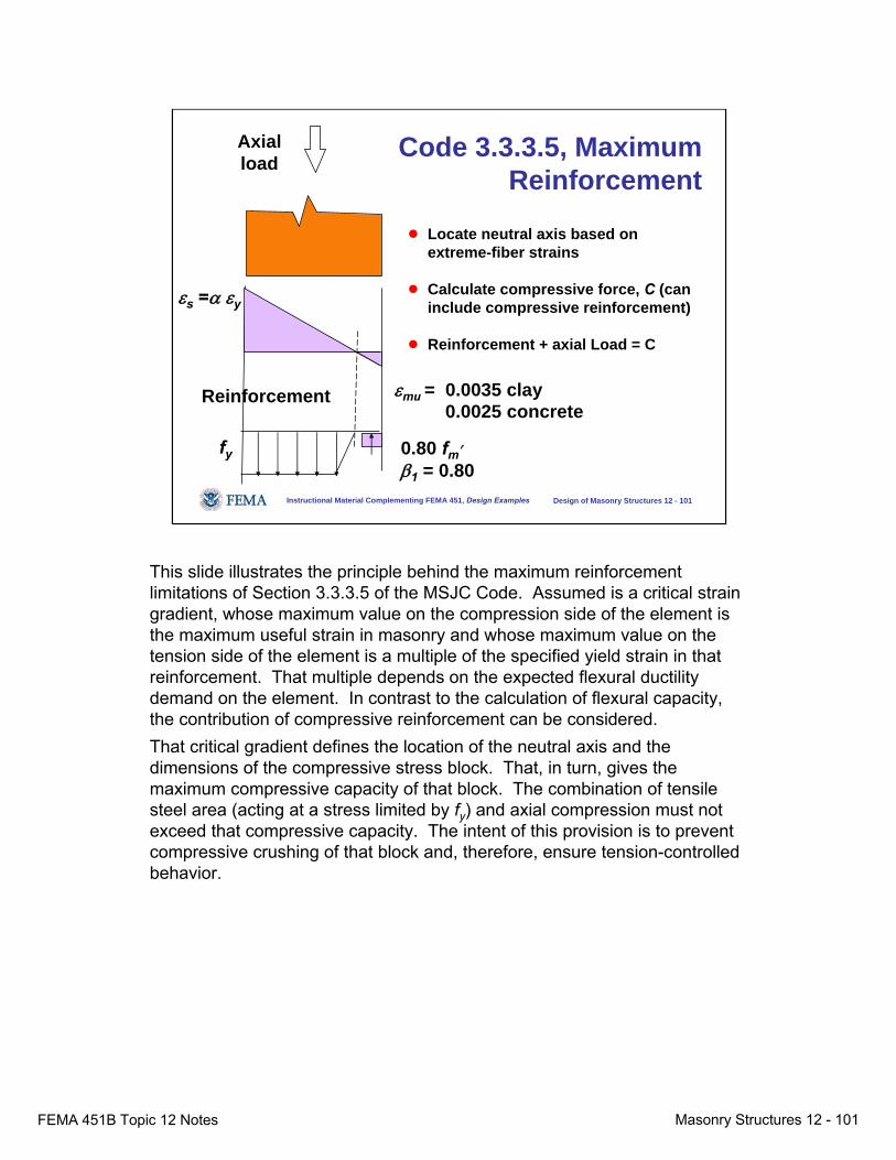
FEMA 451B Topic 12 Notes Masonry Structures 12 - 101
This slide illustrates the principle behind the maximum reinforcement limitations of Section 3.3.3.5 of the MSJC Code. Assumed is a critical strain gradient, whose maximum value on the compression side of the element is the maximum useful strain in masonry and whose maximum value on the tension side of the element is a multiple of the specified yield strain in that reinforcement. That multiple depends on the expected flexural ductility demand on the element. In contrast to the calculation of flexural capacity, the contribution of compressive reinforcement can be considered.That critical gradient defines the location of the neutral axis and the dimensions of the compressive stress block. That, in turn, gives the maximum compressive capacity of that block. The combination of tensile steel area (acting at a stress limited by fy) and axial compression must not exceed that compressive capacity. The intent of this provision is to prevent compressive crushing of that block and, therefore, ensure tension-controlled behavior.
Instructional Material Complementing FEMA 451, Design Examples Design of Masonry Structures 12 - 101
Code 3.3.3.5, Maximum Reinforcement
● Locate neutral axis based on extreme-fiber strains
● Calculate compressive force, C (can include compressive reinforcement)
● Reinforcement + axial Load = C
εs =α εy
fy
Reinforcement
Axialload
0.80 fm′β1 = 0.80
εmu = 0.0035 clay 0.0025 concrete

FEMA 451B Topic 12 Notes Masonry Structures 12 - 102
Instructional Material Complementing FEMA 451, Design Examples Design of Masonry Structures 12 - 102
Code 3.3.4, Design of Beams, Piers, and Columns
● Capacity under combinations of flexure and axial load is based on the assumptions of Code 3.3.2 (interaction diagram)
Pure flexure
Pn
Mn
Pure compression
Balance point
Using the assumptions of Section 3.3.2 of the MSJC Code, capacity of reinforced masonry elements under combinations of flexure and axial load is described using a moment-axial force interaction diagram, just as for reinforced concrete. Such a diagram can be computed by hand for key points, or computed using a spreadsheet for various assumed positions of the neutral axis.
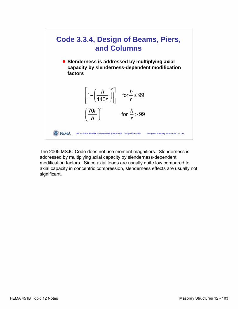
FEMA 451B Topic 12 Notes Masonry Structures 12 - 103
Instructional Material Complementing FEMA 451, Design Examples Design of Masonry Structures 12 - 103
Code 3.3.4, Design of Beams, Piers, and Columns
● Slenderness is addressed by multiplying axial capacity by slenderness-dependent modification factors
2
2
1 for 99140
70 for 99
h hr r
r hh r
⎡ ⎤⎛ ⎞− ≤⎢ ⎥⎜ ⎟⎝ ⎠⎢ ⎥⎣ ⎦
⎛ ⎞ >⎜ ⎟⎝ ⎠
The 2005 MSJC Code does not use moment magnifiers. Slenderness is addressed by multiplying axial capacity by slenderness-dependent modification factors. Since axial loads are usually quite low compared to axial capacity in concentric compression, slenderness effects are usually not significant.
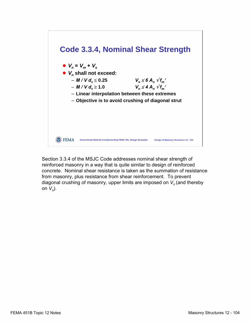
FEMA 451B Topic 12 Notes Masonry Structures 12 - 104
Instructional Material Complementing FEMA 451, Design Examples Design of Masonry Structures 12 - 104
Code 3.3.4, Nominal Shear Strength
● Vn = Vm + Vs
● Vn shall not exceed:– M / V dv ≤ 0.25 Vn ≤ 6 An √ fm′– M / V dv ≥ 1.0 Vn ≤ 4 An √ fm′– Linear interpolation between these extremes– Objective is to avoid crushing of diagonal strut
Section 3.3.4 of the MSJC Code addresses nominal shear strength of reinforced masonry in a way that is quite similar to design of reinforced concrete. Nominal shear resistance is taken as the summation of resistance from masonry, plus resistance from shear reinforcement. To prevent diagonal crushing of masonry, upper limits are imposed on Vn (and thereby on Vs).
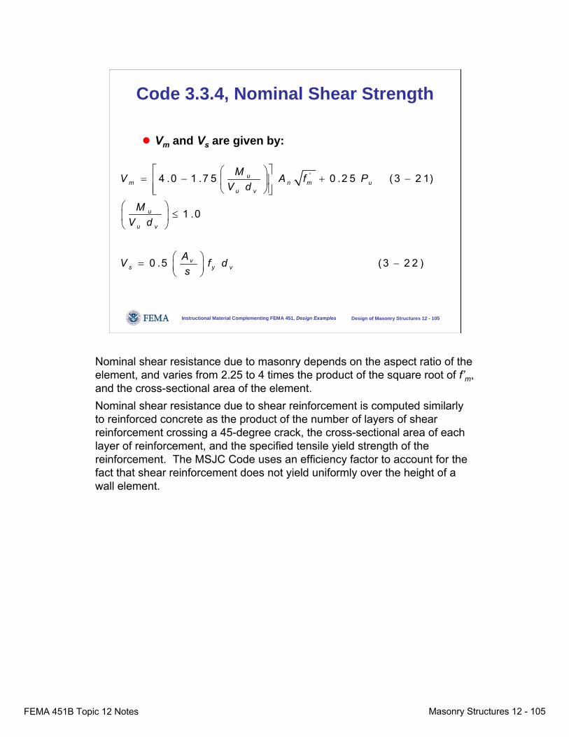
FEMA 451B Topic 12 Notes Masonry Structures 12 - 105
Instructional Material Complementing FEMA 451, Design Examples Design of Masonry Structures 12 - 105
Code 3.3.4, Nominal Shear Strength
● Vm and Vs are given by:
'4 .0 1 .7 5 0 .2 5 (3 2 1)
1 .0
0 .5 (3 2 2 )
um n m u
u v
u
u v
vs y v
MV A f PV d
MV d
AV f ds
⎡ ⎤⎛ ⎞= − + −⎢ ⎥⎜ ⎟
⎢ ⎥⎝ ⎠⎣ ⎦⎛ ⎞
≤⎜ ⎟⎝ ⎠
⎛ ⎞= −⎜ ⎟⎝ ⎠
Nominal shear resistance due to masonry depends on the aspect ratio of the element, and varies from 2.25 to 4 times the product of the square root of f’m, and the cross-sectional area of the element.Nominal shear resistance due to shear reinforcement is computed similarly to reinforced concrete as the product of the number of layers of shear reinforcement crossing a 45-degree crack, the cross-sectional area of each layer of reinforcement, and the specified tensile yield strength of the reinforcement. The MSJC Code uses an efficiency factor to account for the fact that shear reinforcement does not yield uniformly over the height of a wall element.
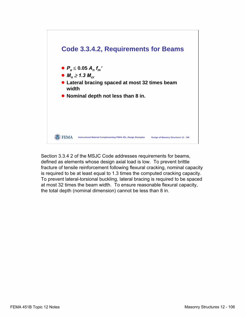
FEMA 451B Topic 12 Notes Masonry Structures 12 - 106
Instructional Material Complementing FEMA 451, Design Examples Design of Masonry Structures 12 - 106
Code 3.3.4.2, Requirements for Beams
● Pu ≤ 0.05 An fm′● Mn ≥ 1.3 Mcr
● Lateral bracing spaced at most 32 times beam width
● Nominal depth not less than 8 in.
Section 3.3.4 2 of the MSJC Code addresses requirements for beams, defined as elements whose design axial load is low. To prevent brittle fracture of tensile reinforcement following flexural cracking, nominal capacity is required to be at least equal to 1.3 times the computed cracking capacity. To prevent lateral-torsional buckling, lateral bracing is required to be spaced at most 32 times the beam width. To ensure reasonable flexural capacity, the total depth (nominal dimension) cannot be less than 8 in.
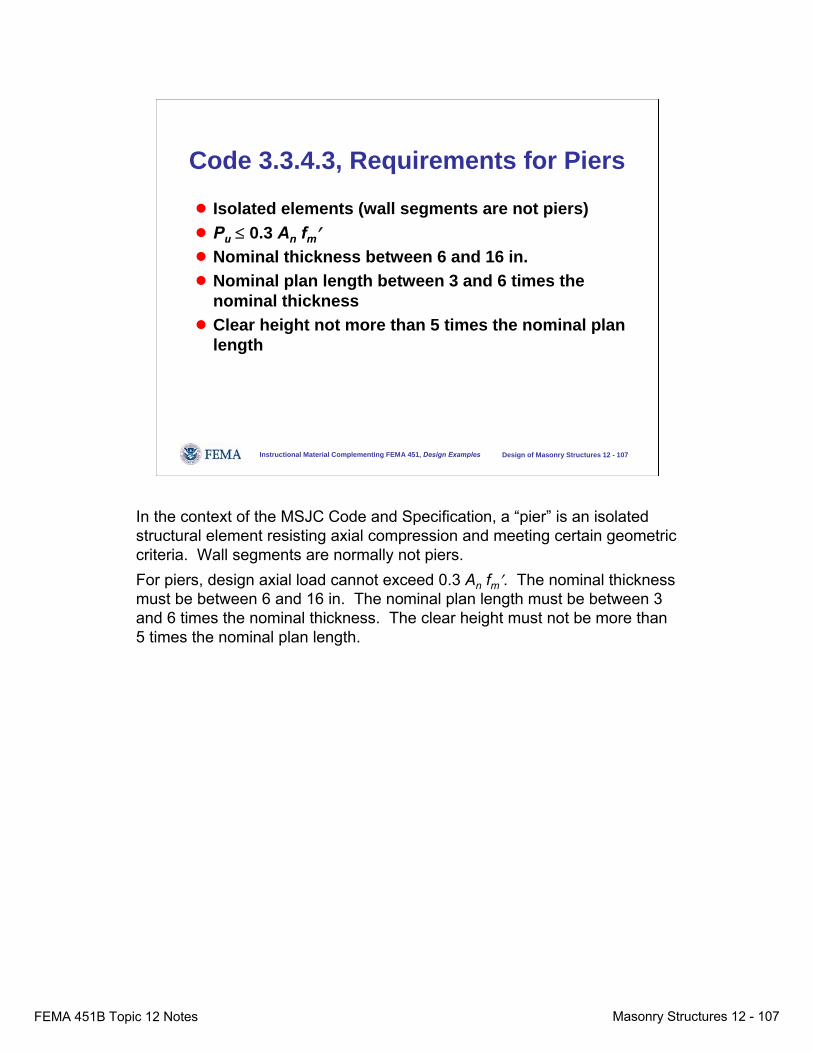
FEMA 451B Topic 12 Notes Masonry Structures 12 - 107
Instructional Material Complementing FEMA 451, Design Examples Design of Masonry Structures 12 - 107
Code 3.3.4.3, Requirements for Piers
● Isolated elements (wall segments are not piers)● Pu ≤ 0.3 An fm′● Nominal thickness between 6 and 16 in.● Nominal plan length between 3 and 6 times the
nominal thickness● Clear height not more than 5 times the nominal plan
length
In the context of the MSJC Code and Specification, a “pier” is an isolated structural element resisting axial compression and meeting certain geometric criteria. Wall segments are normally not piers.For piers, design axial load cannot exceed 0.3 An fm′. The nominal thickness must be between 6 and 16 in. The nominal plan length must be between 3 and 6 times the nominal thickness. The clear height must not be more than 5 times the nominal plan length.

FEMA 451B Topic 12 Notes Masonry Structures 12 - 108
Instructional Material Complementing FEMA 451, Design Examples Design of Masonry Structures 12 - 108
Code 3.3.4.4, Requirements for Columns
● Isolated elements (wall segments are not columns)● ρg ≥ 0.0025● ρg ≤ 0.04, and also meet Code 3.3.3.5● Lateral ties in accordance with Code 2.1.6.5● Solid-grouted● Least cross-section dimension ≥ 8 in.● Nominal depth not greater than 3 times the nominal
width
In the context of the MSJC Code and Specification, a “column” is an isolated structural element resisting axial compression, and meeting certain geometric criteria. Wall segments are normally not columns.Columns must have a ratio of total longitudinal reinforcement to gross cross-sectional area between 0.0025 and 0.04. They must meet maximum flexural reinforcement requirements of Section 3.3.3.5 of the MSJC Code. Longitudinal reinforcement must be supported laterally (tied) in accordance with Section 2.1.6.5 of the MSJC Code. Their least cross-sectional dimension must be at least 8 in., and their nominal depth must not exceed 3 times their nominal width.

FEMA 451B Topic 12 Notes Masonry Structures 12 - 109
Instructional Material Complementing FEMA 451, Design Examples Design of Masonry Structures 12 - 109
Code 3.3.5, Design of Walls for Out-of-plane Loads
● Capacity under combinations of flexure and axial load is based on the assumptions of Code 3.3.2 (interaction diagram)
Pure flexure
Pn
Mn
Pure compression
Balance point
Walls are designed under out-of-plane loads using a strength interaction diagram.
FEMA 451B Topic 12 Notes Masonry Structures 12 - 110
Instructional Material Complementing FEMA 451, Design Examples Design of Masonry Structures 12 - 110
Code 3.3.5, Design of Walls for Out-of-plane Loads
● Maximum reinforcement by Code 3.3.3.5● Procedures for computing out-of-plane moments
and deflections (moment magnifier, vary depending on axial load)
● Nominal shear strength by Code 3.3.4.1.2
Maximum reinforcement requirements are given by Section 3.3.3.5 of the MSJC Code. Slenderness effects are addressed (for walls loaded out of plane only) by computing a magnified moment based on computed out-of-plane deflections. Nominal shear strength is given by Section 3.3.4.1.2.
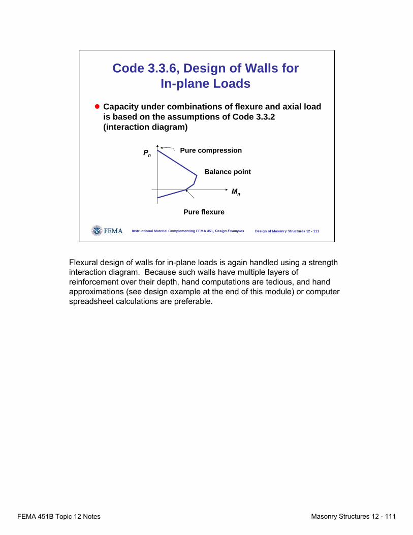
FEMA 451B Topic 12 Notes Masonry Structures 12 - 111
Instructional Material Complementing FEMA 451, Design Examples Design of Masonry Structures 12 - 111
Code 3.3.6, Design of Walls for In-plane Loads
● Capacity under combinations of flexure and axial load is based on the assumptions of Code 3.3.2 (interaction diagram)
Pure flexure
Pn
Mn
Pure compression
Balance point
Flexural design of walls for in-plane loads is again handled using a strength interaction diagram. Because such walls have multiple layers ofreinforcement over their depth, hand computations are tedious, and hand approximations (see design example at the end of this module) or computer spreadsheet calculations are preferable.
FEMA 451B Topic 12 Notes Masonry Structures 12 - 112
Instructional Material Complementing FEMA 451, Design Examples Design of Masonry Structures 12 - 112
Code 3.3.6, Design of Walls for In-plane Loads
● Maximum reinforcement by Code 3.3.3.5● Vertical reinforcement not less than one-half the
horizontal reinforcement● Nominal shear strength by Code 3.3.4.1.2
Code Section 3.3.6 addresses design of walls for in-plane loads. Maximum longitudinal (flexural) reinforcement is specified by Section 3.3.3.5. Nominal shear strength is calculated by Section 3.3.4.1.2. Vertical reinforcement must be at least one-half the horizontal reinforcement. Usually this will not govern since a certain amount of vertical reinforcement is needed to resist out-of-plane loads (see the example at the end of this module).

FEMA 451B Topic 12 Notes Masonry Structures 12 - 113
During the 2005 MSJC cycle, Section 3.3.6 was developed as a “place-holder” to permit the possibility of designing walls with confined boundary elements rather than limiting the amount of flexural reinforcement in them. That section requires detailing requirements for boundary elements to be developed based on experiment. As of 2005, such detailing requirements are not yet available.
Instructional Material Complementing FEMA 451, Design Examples Design of Masonry Structures 12 - 113
Code 3.3.6, Alternative Approach to Maximum Reinforcement
● For walls expected to have flexural ductility in plane, provide confined boundary elements in hinging regions (this is another way of preventing toe crushing)
● Detailing requirements for boundary elements have yet to be developed
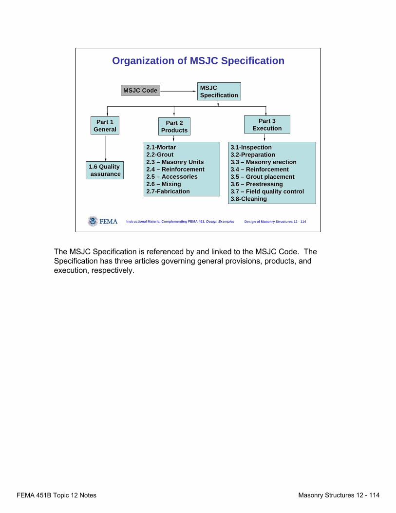
FEMA 451B Topic 12 Notes Masonry Structures 12 - 114
Instructional Material Complementing FEMA 451, Design Examples Design of Masonry Structures 12 - 114
Organization of MSJC Specification
MSJC CodeMSJC Code
Part 1Part 1GeneralGeneral
Part 2Part 2ProductsProducts
Part 3Part 3ExecutionExecution
1.6 Quality1.6 Qualityassuranceassurance
3.13.1--InspectionInspection3.23.2--PreparationPreparation3.3 3.3 –– Masonry erectionMasonry erection3.4 3.4 –– ReinforcementReinforcement3.5 3.5 –– Grout placementGrout placement3.6 3.6 –– PrestressingPrestressing3.7 3.7 –– Field quality controlField quality control3.83.8--CleaningCleaning
2.12.1--Mortar Mortar 2.22.2--GroutGrout2.3 2.3 –– Masonry UnitsMasonry Units2.4 2.4 –– ReinforcementReinforcement2.5 2.5 –– AccessoriesAccessories2.6 2.6 –– MixingMixing2.72.7--FabricationFabrication
MSJCMSJCSpecificationSpecification
The MSJC Specification is referenced by and linked to the MSJC Code. The Specification has three articles governing general provisions, products, and execution, respectively.

FEMA 451B Topic 12 Notes Masonry Structures 12 - 115
Instructional Material Complementing FEMA 451, Design Examples Design of Masonry Structures 12 - 115
Strength Design of Reinforced Masonry Shear Walls
● Compute factored design moments and shears for in- and out-of-plane loading.
● Given practical thickness for wall, design flexural reinforcement as governed by out-of-plane loading.
● Design flexural reinforcement as governed by in-plane loading and revise design as necessary.
● Check shear capacity using capacity design if required.
● Check detailing.
Now let’s look at a specific application of the masonry design provisions that we have seen in this module -- the strength design of reinforced masonry shear walls. That design involves the following steps, listed here and addressed in more detail in subsequent slides.Compute factored design moments and shears for in- and out-of-plane loading.Given practical thickness for wall, design flexural reinforcement as governed by out-of-plane loading.Design flexural reinforcement as governed by in-plane loading, revise design as necessary.Check shear capacity, using capacity design if required.Check detailing.
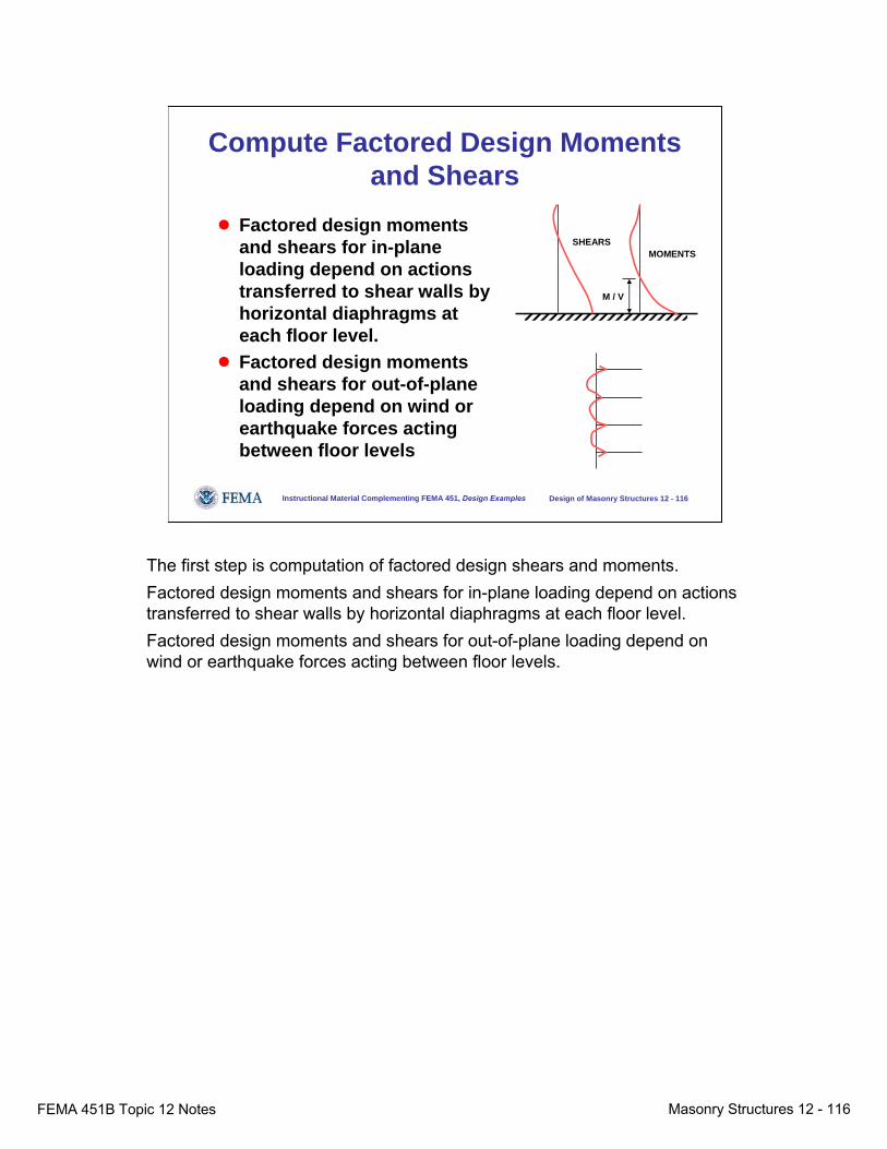
FEMA 451B Topic 12 Notes Masonry Structures 12 - 116
Instructional Material Complementing FEMA 451, Design Examples Design of Masonry Structures 12 - 116
Compute Factored Design Moments and Shears
● Factored design moments and shears for in-plane loading depend on actions transferred to shear walls by horizontal diaphragms at each floor level.
● Factored design moments and shears for out-of-plane loading depend on wind or earthquake forces acting between floor levels
MOMENTSSHEARS
M / V
The first step is computation of factored design shears and moments.Factored design moments and shears for in-plane loading depend on actions transferred to shear walls by horizontal diaphragms at each floor level.Factored design moments and shears for out-of-plane loading depend on wind or earthquake forces acting between floor levels.
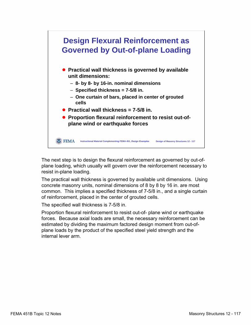
FEMA 451B Topic 12 Notes Masonry Structures 12 - 117
Instructional Material Complementing FEMA 451, Design Examples Design of Masonry Structures 12 - 117
Design Flexural Reinforcement as Governed by Out-of-plane Loading
● Practical wall thickness is governed by available unit dimensions:– 8- by 8- by 16-in. nominal dimensions– Specified thickness = 7-5/8 in.– One curtain of bars, placed in center of grouted
cells● Practical wall thickness = 7-5/8 in.● Proportion flexural reinforcement to resist out-of-
plane wind or earthquake forces
The next step is to design the flexural reinforcement as governed by out-of-plane loading, which usually will govern over the reinforcement necessary to resist in-plane loading.The practical wall thickness is governed by available unit dimensions. Using concrete masonry units, nominal dimensions of 8 by 8 by 16 in. are most common. This implies a specified thickness of 7-5/8 in., and a single curtain of reinforcement, placed in the center of grouted cells.The specified wall thickness is 7-5/8 in.Proportion flexural reinforcement to resist out-of- plane wind or earthquake forces. Because axial loads are small, the necessary reinforcement can be estimated by dividing the maximum factored design moment from out-of-plane loads by the product of the specified steel yield strength and the internal lever arm.

FEMA 451B Topic 12 Notes Masonry Structures 12 - 118
Instructional Material Complementing FEMA 451, Design Examples Design of Masonry Structures 12 - 118
Design Flexural Reinforcement as Governed by In-plane Loading
● Construct moment – axial force interaction diagram– Initial estimate (more later)– Computer programs– Spreadsheets– Tables
Axial Capacity
Flexural Capacity
The next step is to design flexural reinforcement as governed by in-plane loading. A moment-axial force interaction diagram can be computed by hand or by spreadsheet. As an initial estimate for hand calculations, the approach of Cardenas and Magura can also be used, and is discussed in a few more slides.

FEMA 451B Topic 12 Notes Masonry Structures 12 - 119
Instructional Material Complementing FEMA 451, Design Examples Design of Masonry Structures 12 - 119
Strict Limits on Maximum Flexural Reinforcement
● Objective -- Keep compressive stress block from crushing:– Walls must be below balance
point.– Maximum steel percentage
decreases as axial load increases, so that design above balance point is impossible.
Axial Capacity
Flexural Capacity
design prohibited
design permitted
As noted previously, the 2005 MSJC Code places strict limits on maximum flexural reinforcement. To keep the compressive stress block from crushing, the maximum steel percentage decreases as axial load increases so that design above the balance point is impossible.

FEMA 451B Topic 12 Notes Masonry Structures 12 - 120
Instructional Material Complementing FEMA 451, Design Examples Design of Masonry Structures 12 - 120
Revise Design as Necessary● If flexural reinforcement required for out-of-plane
moments is less than or equal to that required for in-plane moments, no adjustment is necessary. Use the larger amount.
● If flexural reinforcement required for out-of-plane moments exceeds that required for in-plane moments, consider making the wall thicker so that in-plane flexural capacity does not have to be increased. Excess in-plane capacity increases shear demand.
After determining the reinforcement required to resist out-of-plane loads, and the reinforcement required to resist in-plane loads, the greater of the two requirements governs. If out-of-plane requirements considerably exceed in-plane requirements, consider making the wall thicker. In-plane over-capacities in flexure can lead to an unacceptable increase in shear demand if capacity design is used (see subsequent example).

FEMA 451B Topic 12 Notes Masonry Structures 12 - 121
Instructional Material Complementing FEMA 451, Design Examples Design of Masonry Structures 12 - 121
Check Shear Capacity (1)● Elastic structures or those with considerable
shear overstrength:– Compute factored design shears based on factored
design actions.● Inelastic structures:
– Compute design shears based on flexural capacity
shears and momentscorresponding to
probable flexural capacity
shears and moments from factored design loads
WALLMOMENTS
WALLSHEARS
M / V
shears and moments corresponding to nominal
flexural capacity
In checking shear capacity, the first step is to estimate the design shear.If the structure is essentially elastic, factored design shears should be computed based on factored design actions.If the structure is expected to have significant inelastic flexural deformation, then capacity design should be used. Design shears should be computed based on flexural capacity.In the above figure, the gray diagrams represent shears and moments from factored design loads. The black diagrams represent shears and moments corresponding to nominal flexural capacity. They are the gray diagrams,divided by the capacity reduction factor for flexure. The red diagrams represent the shears and moments corresponding to the probable flexural capacity. They are the black diagrams, multiplied by the ratio of the probable yield strength of the flexural reinforcement divided by the specified yield strength and also multiplied by the ratio of the probable area of reinforcement divided by the required reinforcement.

FEMA 451B Topic 12 Notes Masonry Structures 12 - 122
Instructional Material Complementing FEMA 451, Design Examples Design of Masonry Structures 12 - 122
Check Shear Capacity (2)
● Vn = Vm + Vs
● Vm depends on (Mu / Vudv) ratio● Vs = (0.5) Av fy (note efficiency factor)
45 o
Σ Av fy
V
As discussed previously, shear resistance is calculated similarly to that of reinforced concrete.
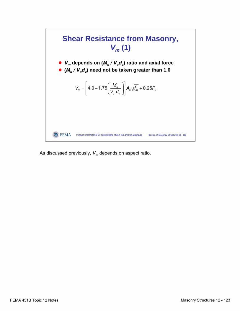
FEMA 451B Topic 12 Notes Masonry Structures 12 - 123
Instructional Material Complementing FEMA 451, Design Examples Design of Masonry Structures 12 - 123
Shear Resistance from Masonry, Vm (1)
● Vm depends on (Mu / Vudv) ratio and axial force● (Mu / Vudv) need not be taken greater than 1.0
'4.0 1.75 0.25um n m u
u v
MV A f PV d
⎡ ⎤⎛ ⎞= − +⎢ ⎥⎜ ⎟⎢ ⎥⎝ ⎠⎣ ⎦
As discussed previously, Vm depends on aspect ratio.

FEMA 451B Topic 12 Notes Masonry Structures 12 - 124
Instructional Material Complementing FEMA 451, Design Examples Design of Masonry Structures 12 - 124
Shear Resistance from Masonry, Vm (2)
Vm / h Lw √ fm’ 10
8
6
4
2
00.5 1.51.0
Mu / Vu dv
P / Lwh = 0 psi
2.25
Shear resistance from masonry varies with aspect ratio as shown in this graph.
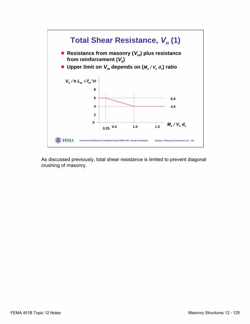
FEMA 451B Topic 12 Notes Masonry Structures 12 - 125
Instructional Material Complementing FEMA 451, Design Examples Design of Masonry Structures 12 - 125
Total Shear Resistance, Vn (1)● Resistance from masonry (Vm) plus resistance
from reinforcement (Vs)● Upper limit on Vm depends on (Mu / Vu dv) ratio
Vn / h Lw √ fm’10
8
6
4
2
00.5 1.51.0 Mu / Vu dv
4.0
0.25
6.0
As discussed previously, total shear resistance is limited to prevent diagonal crushing of masonry.

FEMA 451B Topic 12 Notes Masonry Structures 12 - 126
Instructional Material Complementing FEMA 451, Design Examples Design of Masonry Structures 12 - 126
Check Detailing
● Cover● Placement of flexural and shear reinforcement● Boundary elements not required:
– Ductility demand is low– Maximum flexural reinforcement is closely
controlled
Finally, the designer must check detailing, including cover and placement of flexural and shear reinforcement. Boundary elements are not required because ductility demand is usually low and maximum flexural reinforcement is closely controlled.

FEMA 451B Topic 12 Notes Masonry Structures 12 - 127
Instructional Material Complementing FEMA 451, Design Examples Design of Masonry Structures 12 - 127
Detailing (1)● Cover:
– Automatically satisfied by putting reinforcement in grouted cells
● Placement of flexural and shear reinforcement:– Minimum flexural reinforcement and spacing
dictated by Seismic Design Category– Flexural reinforcement placed in single curtain.
Typical reinforcement would be at least #4 bars @ 48 in.
– Place horizontal reinforcement in single curtain. Typical reinforcement would be at least #4 bars @ 48 in.
– Add more flexural reinforcement if required, usually uniformly distributed.
Detailing requirements are usually not difficult to satisfy.Cover requirements are automatically satisfied by putting reinforcement in grouted cells.Flexural and shear reinforcement must comply with the minimum flexural reinforcement and spacing dictated by the Seismic Design Category. Flexural reinforcement is normally placed in single curtain. Typical reinforcement would be at least #4 bars @ 48 in. Horizontal reinforcement is also placed in the same single curtain.Typical reinforcement would be at least #4 bars @ 48 in. Additional reinforcement (usually uniformly distributed) can be added if required to resist in-plane flexure.

FEMA 451B Topic 12 Notes Masonry Structures 12 - 128
Instructional Material Complementing FEMA 451, Design Examples Design of Masonry Structures 12 - 128
Flexural Strength of Lineal Walls (1)
● Approximation to moment-axial force interaction diagram for low axial load
Axial capacity
Flexural capacity
Now let’s look briefly at Cardenas and Magura’s approximation for flexural strength.
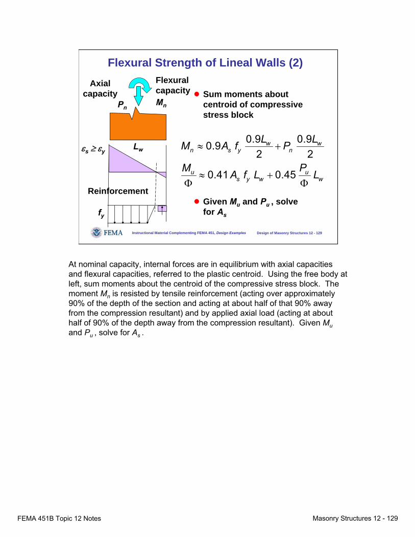
FEMA 451B Topic 12 Notes Masonry Structures 12 - 129
Instructional Material Complementing FEMA 451, Design Examples Design of Masonry Structures 12 - 129
Flexural Strength of Lineal Walls (2)
● Sum moments about centroid of compressive stress block
● Given Mu and Pu , solve for As
εs ≥ εy
fy
Reinforcement
Axialcapacity
Lw
Pn
Flexural capacityMn
0.9 0.90.92 2
0.41 0.45
w wn s y n
u us y w w
L LM A f P
M PA f L L
≈ +
≈ +Φ Φ
At nominal capacity, internal forces are in equilibrium with axial capacities and flexural capacities, referred to the plastic centroid. Using the free body at left, sum moments about the centroid of the compressive stress block. The moment Mn is resisted by tensile reinforcement (acting over approximately90% of the depth of the section and acting at about half of that 90% away from the compression resultant) and by applied axial load (acting at about half of 90% of the depth away from the compression resultant). Given Muand Pu , solve for As .

FEMA 451B Topic 12 Notes Masonry Structures 12 - 130
Instructional Material Complementing FEMA 451, Design Examples Design of Masonry Structures 12 - 130
Design Example (1)● Carry out the preliminary design of the masonry
shear wall shown below. Use fm’ = 1500 psi.
Pu = 100 kipsVu = 80 kips per floor
12 ft
12 ft80 kips
160 kips
Vu diagram
2,880 kip-ft
960 kip-ft
20 ftMu diagram
Now let’s use those principles to carry out the preliminary design of a masonry shear wall. It measures 20 ft in plan; has two stories; and has factored lateral loads of 80 kips on each floor. Factored axial load is 100 kips. Factored design shear and moment diagrams are shown to the right of the slide.

FEMA 451B Topic 12 Notes Masonry Structures 12 - 131
Instructional Material Complementing FEMA 451, Design Examples Design of Masonry Structures 12 - 131
Design Example (2)
● Assume out-of-plane flexure is OK.● Check in-plane flexure using initial estimate.
● This is equivalent to #5 bars @ 12 in.
2
0.41 0.45
2880 12 ./ 1000.41 60 240 . 0.45 240 .0.90 0.9
38,400 5,900 12,000
4.47 .
u us y w w
s
s
s
M PA f L L
kip ft in ft kipsA ksi in in
A
A in
≈ +Φ Φ
− ×≈ × × + ×
≈ +
≈
Assuming that out-of-plane flexure is satisfied, the required area of flexural reinforcement can be calculated. Using the approximate formula derived previously, the required steel area is predicted as 4.47 in.2. This is equivalent to #5 bars @ 12 in.
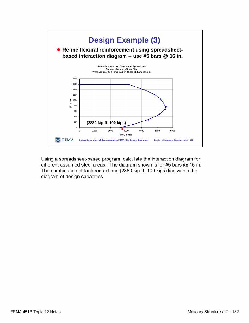
FEMA 451B Topic 12 Notes Masonry Structures 12 - 132
Instructional Material Complementing FEMA 451, Design Examples Design of Masonry Structures 12 - 132
Design Example (3)● Refine flexural reinforcement using spreadsheet-
based interaction diagram -- use #5 bars @ 16 in.
Strength Interaction Diagram by SpreadsheetConcrete Masonry Shear Wall
f'm=1500 psi, 20 ft long, 7.63 in. thick, #5 bars @ 16 in.
0
200
400
600
800
1000
1200
1400
1600
1800
0 1000 2000 3000 4000 5000 6000φMn, ft-kips
φPn,
kip
s
(2880 kip-ft, 100 kips)
Using a spreadsheet-based program, calculate the interaction diagram for different assumed steel areas. The diagram shown is for #5 bars @ 16 in. The combination of factored actions (2880 kip-ft, 100 kips) lies within the diagram of design capacities.
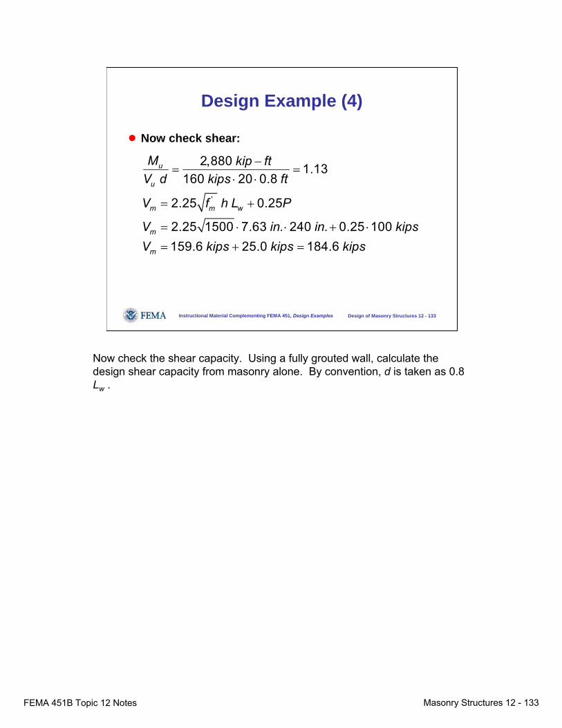
FEMA 451B Topic 12 Notes Masonry Structures 12 - 133
Instructional Material Complementing FEMA 451, Design Examples Design of Masonry Structures 12 - 133
Design Example (4)
● Now check shear:
'
2,880 1.13160 20 0.8
2.25 0.25
2.25 1500 7.63 . 240 . 0.25 100159.6 25.0 184.6
u
u
m m w
m
m
M kip ftV d kips ft
V f h L P
V in in kipsV kips kips kips
−= =
⋅ ⋅
= +
= ⋅ ⋅ + ⋅
= + =
Now check the shear capacity. Using a fully grouted wall, calculate the design shear capacity from masonry alone. By convention, d is taken as 0.8 Lw .
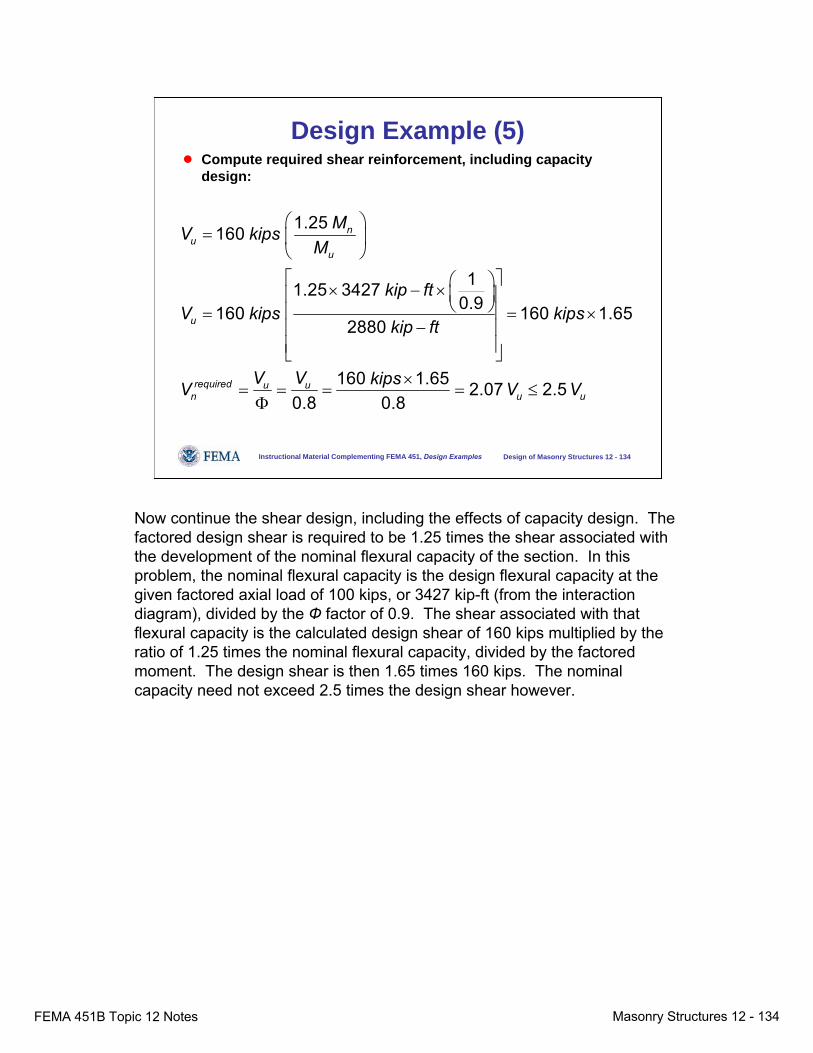
FEMA 451B Topic 12 Notes Masonry Structures 12 - 134
Instructional Material Complementing FEMA 451, Design Examples Design of Masonry Structures 12 - 134
Design Example (5)● Compute required shear reinforcement, including capacity
design:
1.25160
11.25 34270.9160 160 1.65
2880
160 1.65 2.07 2.50.8 0.8
nu
u
u
required u un u u
MV kipsM
kip ftV kips kips
kip ft
V V kipsV V V
⎛ ⎞= ⎜ ⎟
⎝ ⎠⎡ ⎤⎛ ⎞× − × ⎜ ⎟⎢ ⎥⎝ ⎠⎢ ⎥= = ×
−⎢ ⎥⎢ ⎥⎣ ⎦
×= = = = ≤Φ
Now continue the shear design, including the effects of capacity design. The factored design shear is required to be 1.25 times the shear associated with the development of the nominal flexural capacity of the section. In this problem, the nominal flexural capacity is the design flexural capacity at the given factored axial load of 100 kips, or 3427 kip-ft (from the interaction diagram), divided by the Ф factor of 0.9. The shear associated with that flexural capacity is the calculated design shear of 160 kips multiplied by the ratio of 1.25 times the nominal flexural capacity, divided by the factored moment. The design shear is then 1.65 times 160 kips. The nominal capacity need not exceed 2.5 times the design shear however.
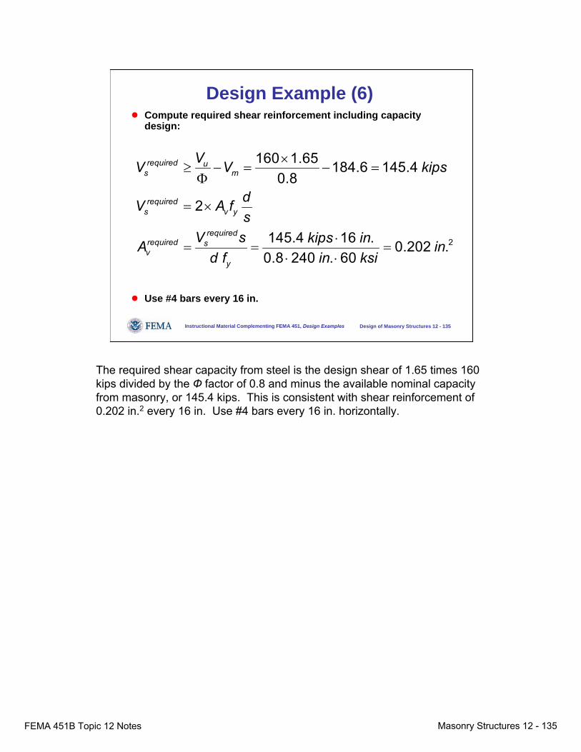
FEMA 451B Topic 12 Notes Masonry Structures 12 - 135
Instructional Material Complementing FEMA 451, Design Examples Design of Masonry Structures 12 - 135
Design Example (6)● Compute required shear reinforcement including capacity
design:
● Use #4 bars every 16 in.
2
160 1.65 184.6 145.40.8
2
145.4 16 . 0.202 .0.8 240 . 60
required us m
requireds v y
requiredrequired sv
y
VV V kips
dV A fs
V s kips inA ind f in ksi
×≥ − = − =Φ
= ×
⋅= = =
⋅ ⋅
The required shear capacity from steel is the design shear of 1.65 times 160 kips divided by the Ф factor of 0.8 and minus the available nominal capacity from masonry, or 145.4 kips. This is consistent with shear reinforcement of 0.202 in.2 every 16 in. Use #4 bars every 16 in. horizontally.
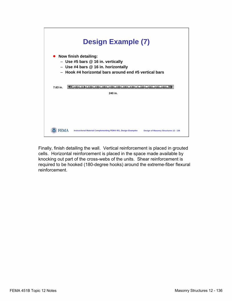
FEMA 451B Topic 12 Notes Masonry Structures 12 - 136
Instructional Material Complementing FEMA 451, Design Examples Design of Masonry Structures 12 - 136
Design Example (7)
● Now finish detailing:– Use #5 bars @ 16 in. vertically– Use #4 bars @ 16 in. horizontally– Hook #4 horizontal bars around end #5 vertical bars
7.63 in.
240 in.
Finally, finish detailing the wall. Vertical reinforcement is placed in grouted cells. Horizontal reinforcement is placed in the space made available by knocking out part of the cross-webs of the units. Shear reinforcement is required to be hooked (180-degree hooks) around the extreme-fiber flexural reinforcement.

FEMA 451B Topic 12 Notes Masonry Structures 12 - 137
Instructional Material Complementing FEMA 451, Design Examples Design of Masonry Structures 12 - 137
Web sites for more information
● BSSC = www.bssconline.org● TMS = www.masonrysociety.org● ACI = www.aci-int.org● ASCE / SEI = www.seinstitute.org● MSJC = www.masonrystandards.org
Further information on the topics presented here is given in these web sites.

FEMA 451B Topic 12 Notes Masonry Structures 12 - 138
Instructional Material Complementing FEMA 451, Design Examples Design of Masonry Structures 12 - 138
Acknowledgements
● This material on masonry was prepared by Prof. Richard E. Klingner, University of Texas at Austin.
● Some of the material was originally prepared by Prof. Klingner for a US Army short course.
● Some of the material was originally prepared by Prof. Klingner for The Masonry Society and is used with their permission.