Embed Size (px)
Citation preview
NEHRP Seismic Design Technical Brief No. 3
Seismic Design of Cast-in-Place Concrete Diaphragms, Chords, and CollectorsA Guide for Practicing Engineers
NIST GCR 10-917-4
Jack P. MoehleJohn D. HooperDominic J. KellyThomas R. Meyer

About The AuthorsJack P. Moehle, Ph.D., P.E., is Professor of Civil and Environmental Engineering at the University of California, Berkeley, where he teaches and conducts research on earthquake-resistant concrete construction. He is Fellow of the American Concrete Institute, and has served on the ACI Code Committee 318 since 1989 and as chair of the seismic subcommittee since 1995. He is a Fellow of the Structural Engineers Association of California and Honorary Member of the Structural Engineers Association of Northern California.
John D. Hooper, P.E., S.E., is Director of Earthquake Engineering at Magnusson Klemencic Associates, a structural and civil engineering firm headquartered in Seattle, Washington. He is a member of the Building Seismic Safety Council’s 2014 Provisions Update Committee and chair of the American Society of Civil Engineers Seismic Subcommittee for ASCE 7-10.
About the Review PanelThe contributions of the three review panelists for this publication are gratefully acknowledged.
S. K. Ghosh, Ph.D. is President, S. K. Ghosh Associates, Inc., Palatine, IL and Aliso Viejo, CA. He and the firm specialize in seismic and building code consulting. He is a Fellow of the American Concrete Institute and serves on ACI Committee 318, the ASCE 7 Committee, and the Seismic Subcommittee of ASCE 7.
Rafael Sabelli, P.E., S.E., is Director of Seismic Design at Walter P Moore, a structural and civil engineering firm with offices nationwide. He is a member of the Building Seismic Safety Council’s 2014 Provisions Update Committee and of the American Society of Civil Engineers Seismic Subcommittee for ASCE 7-10.
Manny Morden, P.E., S.E., MMSE Consulting Structural Engineer, and Principal with Brandow & Johnston, Inc., in Los Angeles, California, is a consulting structural engineer with extensive reinforced concrete design experience. He is a Fellow of the Structural Engineers Association of California and Past President of the Southern California Structural Engineers Association.
National Institute of Standards and Technology
The National Institute of Standards and Technology (NIST) is a federal technology agency within the U.S. Department of Commerce that promotes U.S. innovation and industrial competitiveness by advancing measurement science, standards, and technology in ways that enhance economic security and improve our quality of life. It is the lead agency of the National Earthquake Hazards Reduction Program (NEHRP). Dr. John (Jack) R. Hayes is the Director of NEHRP, within NIST’s Building and Fire Research Laboratory (BFRL). Dr. Jeffrey J. Dragovich managed the project for BFRL.
NEHRP Consultants Joint VentureThis NIST-funded publication is one of the products of the work of the NEHRP Consultants Joint Venture carried out under Contract SB 134107CQ0019, Task Order 69188. The partners in the NEHRP Consultants Joint Venture are the Applied Technology Council (ATC) and the Consortium of Universities for Research in Earthquake Engineering (CUREE). The members of the Joint Venture Management Committee are James R. Harris, Robert Reitherman, Christopher Rojahn, and Andrew Whittaker, and the Program Manager is Jon A. Heintz. Assisting the Program Manager is ATC Senior Management Consultant David A. Hutchinson, who on this Technical Brief provided substantial assistance in the development of the content.
Consortium of Universities for Research in Earthquake Engineering (CUREE)1301 South 46th Street - Building 420Richmond, CA 94804(510) 665-3529www.curee.org email: [email protected]
Applied Technology Council (ATC)201 Redwood Shores Parkway - Suite 240Redwood City, California 94065(650) 595-1542www.atcouncil.org email: [email protected]
NEHRP Seismic Design Technical BriefsNEHRP (National Earthquake Hazards Reduction Program) Technical Briefs are published by NIST, the National Institute of Standards and Technology, as aids to the efficient transfer of NEHRP and other research into practice, thereby helping to reduce the nation’s losses from earthquakes.
Dominic J. Kelly, P.E., S.E., is an Associate Principal of Simpson Gumpertz & Heger Inc. in Waltham, MA where he designs, rehabilitates, and investigates building and non-building structures. He is a Fellow of the American Concrete Institute, and has served on ACI Code Committee 318 since 2003. He has served as a member of the Seismic Code Committee of ASCE 7 since 2000.
Thomas R. Meyer, S.E. is a structural engineer and associate of Magnussen Klemencic Associates, a structural and civil engineering firm headquartered in Seattle, Washington. He is the firm’s in-house diaphragm specialist, and has experience designing a number of building types including high-rise residential towers, museums, performing arts centers, and higher education facilities.

ByJack P. Moehle, Ph.D., P.E.
University of California, BerkeleyBerkeley, California
John D, Hooper, P.E., S.E.Magnusson Klemencic Associates
Seattle, Washington
Dominic J. Kelly, P.E., S.E.Simpson Gumpertz & Heger Inc.
Waltham, Massachusetts
Thomas R. Meyer, S.E.Magnusson Klemencic Associates
Seattle, Washington
August 2010
Prepared forU.S. Department of Commerce
Building and Fire Research LaboratoryNational Institute of Standards and Technology
Gaithersburg, MD 20899-8600
Seismic Design ofCast-in-Place Concrete Diaphragms
Chords, and CollectorsA Guide for Practicing Engineers
NIST GCR 10-917-4
U.S. Department of CommerceGary Locke, Secretary
National Institute of Standards and TechnologyPatrick Gallagher, Director

Disclaimers
The policy of the National Institute of Standards and Technology is to use the International System of Units (metric units) in all of its publications. However, in North America in the construction and building materials industry, certain non-SI units are so widely used instead of SI units that it is more practical and less confusing to include measurement values for customary units only.
This publication was produced as part of contract SB134107CQ0019, Task Order 69188 with the National Institute of Standards and Technology. The contents of this publication do not necessarily reflect the views or policies of the National Institute of Standards and Technology or the US Government.
This Technical Brief was produced under contract to NIST by the NEHRP Consultants Joint Venture, a joint venture of the Applied Technology Council (ATC) and the Consortium of Universities for Research in Earthquake Engineering (CUREE). While endeavoring to provide practical and accurate information in this publication, the NEHRP Consultants Joint Venture, the authors, and the reviewers do not assume liability for, nor make any expressed or implied warranty with regard to, the use of its information. Users of the information in this publication assume all liability arising from such use.
Cover photo – Collector spread into slab adjacent to shear wall.
How to Cite This PublicationMoehle, Jack P., Hooper, John D., Kelly, Dominic J., and Meyer, Thomas R. (2010). “Seismic design of cast-in-place concrete diaphragms, chords, and collectors: a guide for practicing engineers,” NEHRP Seismic Design Technical Brief No. 3, produced by the NEHRP Consultants Joint Venture, a partnership of the Applied Technology Council and the Consortium of Universities for Research in Earthquake Engineering, for the National Institute of Standards and Technology, Gaithersburg, MD, NIST GCR 10-917-4.
Introduction..................................................................................................................1The Roles of Diaphragms...............................................................................................2Diaphragm Components..............................................................................................3Diaphragm Behavior and Design Principles....................................................................4Building Analysis Guidance...........................................................................................7Diaphragm Analysis Guidance....................................................................................11Design Guidance........................................................................................................17Additional Requirements............................................................................................21Detailing & Constructability Issues...............................................................................23References................................................................................................................26Notations and Abbreviations.......................................................................................27Credits.......................................................................................................................29
1. 2.3. 4. 5. 6. 7. 8. 9.
10.11.12.
Contents

1Seismic Design of Cast-in-Place Concrete Diaphragms, Chords, and Collectors: A Guide for Practicing Engineers
Building structures generally comprise a three-dimensional framework of structural elements configured to support gravity and lateral loads. Although the complete three-dimensional system acts integrally to resist loads, we commonly conceive of the seismic force-resisting system as being composed of vertical elements, horizontal elements, and the foundation (Figure 1-1). The vertical elements extend between the foundation and the elevated levels, providing a continuous load path to transmit gravity and seismic forces from the upper levels to the foundation. The horizontal elements typically consist of diaphragms, including collectors. Diaphragms transmit inertial forces from the floor system to the vertical elements of the seismic force-resisting system. They also tie the vertical elements together and thereby stabilize and transmit forces among these elements as may be required during earthquake shaking. Diaphragms are thus an essential part of the seismic force-resisting system and require design attention by the structural engineer to ensure the structural system performs adequately during earthquake shaking.
Figure 1-1 – Isometric view of a basic building structural system comprising horizontal spanning elements (diaphragms), vertical spanning
elements (walls and frames), and foundation.
Diaphragms are required to be designed as part of the seismic force-resisting system of every new building assigned to Seismic Design Category B, C, D, E, or F of the International Building Code (IBC 2009, referred to here as the IBC). Although horizontal elements can consist of truss elements or horizontal diagonal bracing, in most cases diaphragms are constructed as essentially solid, planar elements made of wood, steel, concrete, or combinations of these. Concrete diaphragms can be conventionally reinforced or prestressed, and can be cast-in-place concrete, topping slabs on metal deck or precast concrete, or interconnected precast concrete without topping, though the last system is seldom used in structures assigned to Seismic Design Categories D, E, or F. The scope of this Guide is restricted to cast-in-place concrete diaphragms, either
1. Introductionconventionally reinforced or prestressed. However, many of the concepts that are presented here apply equally to other diaphragm types.
The design requirements for concrete diaphragms are contained in the IBC, which establishes general regulations for buildings, Minimum Design Loads for Buildings and Other Structures (ASCE/SEI 7-10) (ASCE 2010, referred to here as ASCE 7), which focuses on determination of design forces, and Building Code Requirements for Structural Concrete (ACI 318-08) and Commentary (ACI 2008, referred to here as ACI 318), which focuses on proportioning and detailing requirements. In this Guide we refer to these editions, even though some of them may not be adopted in all jurisdictions, and some may refer to earlier editions of the other codes. In general, these three documents are well coordinated regarding terminology, system definition, application limitations, and overall approach.
By comparison with requirements for vertical elements of the seismic-force-resisting system, code provisions for diaphragms are relatively brief. Consequently, many aspects of diaphragm design are left open to interpretation and engineering judgment. The writers of this Guide consulted widely with code writers and practicing engineers to gather a range of good practices applicable to common diaphragm design conditions.
This Guide was written for practicing structural engineers to assist in their understanding and application of code requirements for the design of cast-in-place concrete diaphragms. The material is presented in a sequence that practicing engineers have found useful, with general principles presented first, followed by detailed design requirements. Although this Guide is intended especially for the practicing structural engineer, it will also be useful for building officials, educators, and students.
This Guide emphasizes code requirements and accepted approaches to their implementation. It includes background information and illustrative sketches. Sidebars embedded in the main text provide additional guidance. Sections 2, 3, and 4 introduce diaphragms and diaphragm design principles. Sections 5 and 6 present analysis guidance and Sections 7, 8, and 9 describe proportioning, detailing, and construction requirements for cast-in-place concrete diaphragms. Sections 10, 11, and 12 present cited references, notation and abbreviations, and credits.
Sidebars in This Guide
Sidebars are used in this Guide to illustrate key points, to highlight construction issues, and to provide additional guidance on good practices and open issues in analysis, design, and construction.
Seismic Design of Cast-in-Place Concrete Diaphragms, Chords, and Collectors: A Guide for Practicing Engineers
2
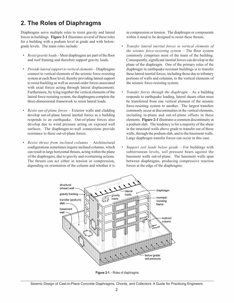
Diaphragms serve multiple roles to resist gravity and lateral forces in buildings. Figure 2-1 illustrates several of these roles for a building with a podium level at grade and with below-grade levels. The main roles include:
Resist gravity loads – Most diaphragms are part of the floor and roof framing and therefore support gravity loads.
Provide lateral support to vertical elements – Diaphragms connect to vertical elements of the seismic force-resisting system at each floor level, thereby providing lateral support to resist buckling as well as second-order forces associated with axial forces acting through lateral displacements. Furthermore, by tying together the vertical elements of the lateral force-resisting system, the diaphragms complete the three-dimensional framework to resist lateral loads.
Resist out-of-plane forces – Exterior walls and cladding develop out-of-plane lateral inertial forces as a building responds to an earthquake. Out-of-plane forces also develop due to wind pressure acting on exposed wall surfaces. The diaphragm-to-wall connections provide resistance to these out-of-plane forces.
Resist thrust from inclined columns – Architectural configurations sometimes require inclined columns, which can result in large horizontal thrusts, acting within the plane of the diaphragms, due to gravity and overturning actions. The thrusts can act either in tension or compression, depending on orientation of the column and whether it is
2. The Roles of Diaphragms in compression or tension. The diaphragm or components within it need to be designed to resist these thrusts.
Transfer lateral inertial forces to vertical elements of the seismic force-resisting system – The floor system commonly comprises most of the mass of the building. Consequently, significant inertial forces can develop in the plane of the diaphragm. One of the primary roles of the diaphragm in earthquake-resistant buildings is to transfer these lateral inertial forces, including those due to tributary portions of walls and columns, to the vertical elements of the seismic force-resisting system.
Transfer forces through the diaphragm – As a building responds to earthquake loading, lateral shears often must be transferred from one vertical element of the seismic force-resisting system to another. The largest transfers commonly occur at discontinuities in the vertical elements, including in-plane and out-of-plane offsets in these elements. Figure 2-1 illustrates a common discontinuity at a podium slab. The tendency is for a majority of the shear in the structural walls above grade to transfer out of those walls, through the podium slab, and to the basement walls. Large diaphragm transfer forces can occur in this case.
Support soil loads below grade – For buildings with subterranean levels, soil pressure bears against the basement walls out-of-plane. The basement walls span between diaphragms, producing compressive reaction forces at the edge of the diaphragms.
•
•
•
•
•
•
•
Figure 2-1 – Roles of diaphragms.

3Seismic Design of Cast-in-Place Concrete Diaphragms, Chords, and Collectors: A Guide for Practicing Engineers
Figure 3-1 – Tension and compression chords.
Figure 3-2 – Collectors.
Diaphragms are commonly composed of various components, including the diaphragm slab, chords, collectors (also known as drag struts or distributors), and connections to the vertical elements.
Figure 3-1 illustrates a simplified model of how a diaphragm resists in-plane loads and identifies its parts. (See Section 6 for additional diaphragm models.) Here, a solid rectangular diaphragm spans between two end walls, with lateral inertial loading indicated schematically by the arrow at the top of the figure. The diaphragm could be modeled as a beam spanning between two supports, with reactions and shear and moment diagrams as shown (Figure 3-1b). Bending moment Mu can be resisted by a tension (Tu) and compression (Cu) couple (Figure 3-1c). The components at the diaphragm boundary acting in tension and compression are known as the tension chord and the compression chord, respectively.
3. Diaphragm Components
If the diaphragm moment is resisted by tension and compression chords at the boundaries of the diaphragm as shown in Figure 3-1a, then equilibrium requires that the diaphragm shear be distributed uniformly along the depth of the diaphragm as shown in Figure 3-1c. Tension and compression elements called collectors are required to “collect” this shear and transmit it to the walls. A collector can transmit all its forces into the ends of the walls as shown on the right side of Figure 3-2a, or if the forces and resulting congestion are beyond practical limits, the collector can be spread into the adjacent slab as shown on the left side of Figure 3-2a. Section 6.2.2 discusses the effective width of a collector spread into a slab.
Figure 3-2b illustrates how the tension and compression forces in the collector are determined for the case where the width of the collector is the same as that of the wall. Starting at a free end, the tension or compression force increases linearly as shear is transferred into the collector. Section 6 discusses the slightly more complicated force transfer where the collector is wider than the wall.
Diaphragms also transfer load among vertical elements of the seismic force-resisting system. A common example is where a wall intersects a podium slab in a building with subterranean levels. In this case, shear is transferred from the wall into the diaphragm and from there to other elements such as basement walls. This element transferring the force from the wall to the diaphragm is a collector, but sometimes is referred to as a distributor. See Figure 3-3. As used in this Guide, a collector is an element that takes distributed load from the diaphragm and delivers it to a vertical element, whereas a distributor takes force from a vertical element and distributes it into the diaphragm.
Figure 3-3 – Distributor.
(a) Plan (b) Collector actions
(a) Plan
(b) Simple beam idealization
(c) Internal moment and shear resistance
Seismic Design of Cast-in-Place Concrete Diaphragms, Chords, and Collectors: A Guide for Practicing Engineers
4
4.1 Dynamic Response of Buildings and Diaphragms
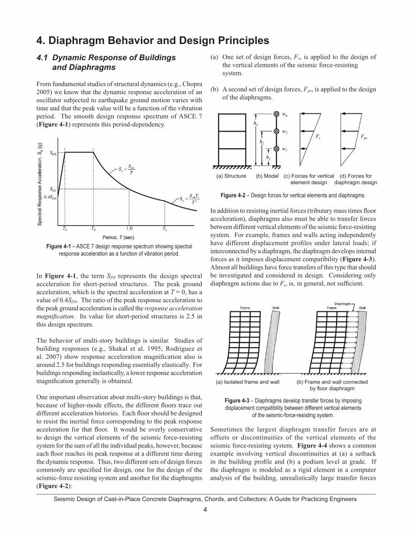
From fundamental studies of structural dynamics (e.g., Chopra 2005) we know that the dynamic response acceleration of an oscillator subjected to earthquake ground motion varies with time and that the peak value will be a function of the vibration period. The smooth design response spectrum of ASCE 7 (Figure 4-1) represents this period-dependency.
4. Diaphragm Behavior and Design Principles
In Figure 4-1, the term SDS represents the design spectral acceleration for short-period structures. The peak ground acceleration, which is the spectral acceleration at T = 0, has a value of 0.4SDS. The ratio of the peak response acceleration to the peak ground acceleration is called the response acceleration magnification. Its value for short-period structures is 2.5 in this design spectrum.
The behavior of multi-story buildings is similar. Studies of building responses (e.g., Shakal et al. 1995; Rodriguez et al. 2007) show response acceleration magnification also is around 2.5 for buildings responding essentially elastically. For buildings responding inelastically, a lower response acceleration magnification generally is obtained.
One important observation about multi-story buildings is that, because of higher-mode effects, the different floors trace out different acceleration histories. Each floor should be designed to resist the inertial force corresponding to the peak response acceleration for that floor. It would be overly conservative to design the vertical elements of the seismic force-resisting system for the sum of all the individual peaks, however, because each floor reaches its peak response at a different time during the dynamic response. Thus, two different sets of design forces commonly are specified for design, one for the design of the seismic-force resisting system and another for the diaphragms (Figure 4-2):
Figure 4-1 – ASCE 7 design response spectrum showing spectral response acceleration as a function of vibration period.
One set of design forces, Fx, is applied to the design of the vertical elements of the seismic force-resisting system.
A second set of design forces, Fpx, is applied to the design of the diaphragms.
In addition to resisting inertial forces (tributary mass times floor acceleration), diaphragms also must be able to transfer forces between different vertical elements of the seismic force-resisting system. For example, frames and walls acting independently have different displacement profiles under lateral loads; if interconnected by a diaphragm, the diaphragm develops internal forces as it imposes displacement compatibility (Figure 4-3). Almost all buildings have force transfers of this type that should be investigated and considered in design. Considering only diaphragm actions due to Fpx is, in general, not sufficient.
Figure 4-2 – Design forces for vertical elements and diaphragms.
Figure 4-3 – Diaphragms develop transfer forces by imposing displacement compatibility between different vertical elements
of the seismic-force-resisting system.
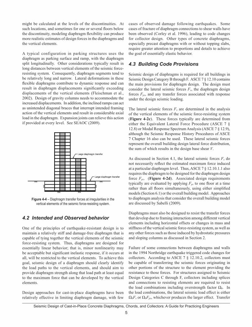
Sometimes the largest diaphragm transfer forces are at offsets or discontinuities of the vertical elements of the seismic force-resisting system. Figure 4-4 shows a common example involving vertical discontinuities at (a) a setback in the building profile and (b) a podium level at grade. If the diaphragm is modeled as a rigid element in a computer analysis of the building, unrealistically large transfer forces
(a)
(b)
(a) Structure (b) Model (c) Forces for vertical element design
(d) Forces for diaphragm design
(a) Isolated frame and wall (b) Frame and wall connected by floor diaphragm
5Seismic Design of Cast-in-Place Concrete Diaphragms, Chords, and Collectors: A Guide for Practicing Engineers
might be calculated at the levels of the discontinuities. At such locations, and sometimes for one or several floors below the discontinuity, modeling diaphragm flexibility can produce more realistic estimates of design forces in the diaphragms and the vertical elements.
A typical configuration in parking structures uses the diaphragm as parking surface and ramp, with the diaphragm split longitudinally. Other considerations typically result in long distances between vertical elements of the seismic force-resisting system. Consequently, diaphragm segments tend to be relatively long and narrow. Lateral deformations in these flexible diaphragms contribute to dynamic response and can result in diaphragm displacements significantly exceeding displacements of the vertical elements (Fleischman et al., 2002). Design of gravity columns needs to accommodate the increased displacements. In addition, the inclined ramps can act as unintended diagonal braces that interrupt intended framing action of the vertical elements and result in considerable axial load in the diaphragm. Expansion joints can relieve this action if provided at every level. See SEAOC (2009).
Figure 4-4 – Diaphragm transfer forces at irregularities in the vertical elements of the seismic force-resisting system.
4.2 Intended and Observed behavior
One of the principles of earthquake-resistant design is to maintain a relatively stiff and damage-free diaphragm that is capable of tying together the vertical elements of the seismic force-resisting system. Thus, diaphragms are designed for essentially linear behavior; that is, minor nonlinearity may be acceptable but significant inelastic response, if it occurs at all, will be restricted to the vertical elements. To achieve this goal, seismic design of a diaphragm should clearly identify the load paths to the vertical elements, and should aim to provide diaphragm strength along that load path at least equal to the maximum force that can be developed by the vertical elements.
Design approaches for cast-in-place diaphragms have been relatively effective in limiting diaphragm damage, with few
cases of observed damage following earthquakes. Some cases of fracture of diaphragm connections to shear walls have been observed (Corley et al. 1996), leading to code changes for collector design. Other types of concrete diaphragms, especially precast diaphragms with or without topping slabs, require greater attention to proportions and details to achieve the goal of essentially elastic behavior.
4.3 Building Code Provisions
Seismic design of diaphragms is required for all buildings in Seismic Design Category B through F. ASCE 7 § 12.10 contains the main provisions for diaphragm design. The design must consider the lateral seismic forces Fx, the diaphragm design forces Fpx, and any transfer forces associated with response under the design seismic loading.
The lateral seismic forces Fx are determined in the analysis of the vertical elements of the seismic force-resisting system (Figure 4-2c). These forces typically are determined from either the Equivalent Lateral Force Procedure (ASCE 7 § 12.8) or Modal Response Spectrum Analysis (ASCE 7 § 12.9), although the Seismic Response History Procedures of ASCE 7 Chapter 16 also can be used. These lateral seismic forces represent the overall building design lateral force distribution, the sum of which results in the design base shear V.
As discussed in Section 4.1, the lateral seismic forces Fx do not necessarily reflect the estimated maximum force induced at a particular diaphragm level. Thus, ASCE 7 § 12.10.1.1 also requires the diaphragm to be designed for the diaphragm design force Fpx. (Figure 4-2d). Associated design requirements typically are evaluated by applying Fpx to one floor at a time rather than all floors simultaneously, using either simplified models (Section 6.1) or the overall building model. Approaches to diaphragm analysis that consider the overall building model are discussed by Sabelli (2009).
Diaphragms must also be designed to resist the transfer forces that develop due to framing interaction among different vertical elements including horizontal offsets or changes in mass and stiffness of the vertical seismic force-resisting system, as well as any other forces such as those induced by hydrostatic pressures and sloping columns as discussed in Section 2.
Failure of some connections between diaphragms and walls in the 1994 Northridge earthquake triggered code changes for collectors. According to ASCE 7 § 12.10.2, collectors must be capable of transferring the seismic forces originating in other portions of the structure to the element providing the resistance to those forces. For structures assigned to Seismic Design Categories C through F, collectors including splices and connections to resisting elements are required to resist the load combinations including overstrength factor Ω0. In the load combinations, the lateral seismic load effect is either Ω0Fx or Ω0Fpx, whichever produces the larger effect. Transfer

Seismic Design of Cast-in-Place Concrete Diaphragms, Chords, and Collectors: A Guide for Practicing Engineers
6
forces are added to those calculated using Section 12.10.2 and are subject to either the overstrength factor or the redundancy factor, depending upon the specific condition being evaluated (see 5.1.2 in this Guide).
Once the forces are determined using the ASCE 7 provisions, reinforced concrete diaphragms and their connections must be designed to resist all shears, moments, and axial forces, including effects of openings and other discontinuities. For buildings assigned to Seismic Design Categories D through F, the provisions of ACI 318 § 21.11 apply. For buildings assigned to Seismic Design Categories B or C, the general requirements in Chapters 1 through 18 apply.
To reduce the likelihood that shear strength of a diaphragm will be less than shear strength of the vertical elements to which it delivers its forces, ACI 318 § 9.3.4 requires that the strength reduction factor f for diaphragm shear not exceed the minimum f used for shear design of the vertical elements of the seismic force-resisting system. For example, if all the vertical elements of the seismic force-resisting system are shear walls that use a value of f = 0.75 for shear, the value of f for diaphragm shear design also is 0.75; if the shear walls use a value of f = 0.6 for shear, as is required if capacity design concepts are not applied in the wall design, then the value of f for diaphragm shear design also is 0.6.
Sections 5 through 9 of this Guide provide detailed code provisions and guidance on how to use them.
4.4 Alternative Approaches
There are alternative approaches to determine design forces in diaphragms and collectors. In performance-based seismic design, a nonlinear response history analysis typically is used. Ground motions sometimes are selected and scaled with a focus on the fundamental period of vibration; however, because peak diaphragm accelerations and design forces may be determined by higher vibration modes, the selection and scaling procedure needs to properly address those vibration modes. Diaphragm accelerations and the resulting forces can be determined directly from the analysis. If diaphragms are modeled as finite elements, section cuts can be used to track diaphragm forces at each time step. As with any computer model, the engineer should exercise good judgment when using the results of a nonlinear response history analysis.
Nonlinear Dynamic Analysis Guidance
Nonlinear response history analysis is sometimes used to determine forces in collectors and their connections, as an alternative to using Ω0-amplified forces Fx and Fpx. This approach can be acceptable if the analysis and design approach are established to achieve the intent of the code that the collector not be the weak link in the load path. Collector demands should be determined using an appropriate estimate of the materials properties (for example, expected materials properties) and should consider the vari-ability in demands produced by different design-level earthquake ground motions. Likewise, the collector design strengths should be determined using a con-servative estimate (for example, the design strength using nominal material properties and the code strength reduction factor). By appropriate selection of the design demands and strengths, an acceptably low probability of failure can be achieved.
See also NEHRP Seismic Design Technical Brief No. 4 “Nonlinear Structural Analysis for Seismic Design” (Deierlein et al. 2010).
Capacity-based design is another way to determine diaphragm design forces. This approach uses the maximum force that can be delivered to a diaphragm by the framing system as the design force, and the reliable resistance as the design strength. The approach may be suitable for levels with significant transfers (such as podium slabs) but overly conservative for other levels. Where capacity-based design is used, engineers should consider expected material properties, multiple failure mechanisms, multiple load patterns, and appropriate strength calculation procedures so that the resulting demands and capacities safely cover the range of combinations that reasonably can be expected.
7Seismic Design of Cast-in-Place Concrete Diaphragms, Chords, and Collectors: A Guide for Practicing Engineers
5.1 Design Lateral Forces
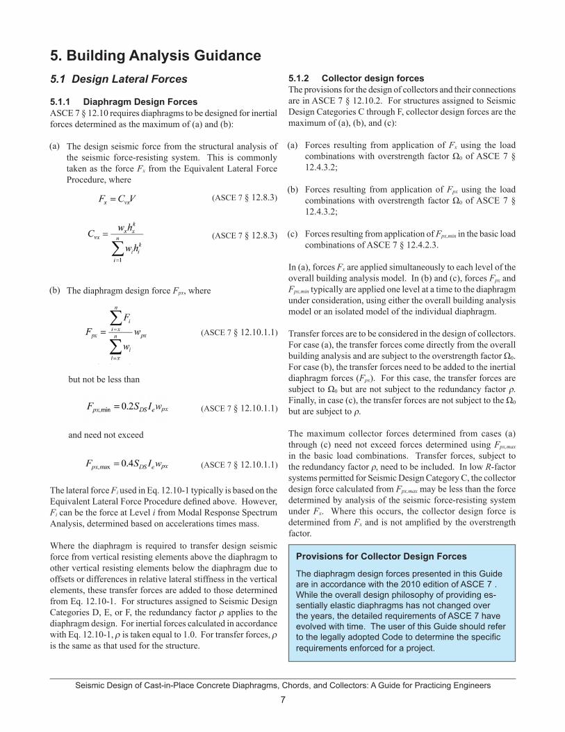
5.1.1 Diaphragm Design Forces ASCE 7 § 12.10 requires diaphragms to be designed for inertial forces determined as the maximum of (a) and (b):
The design seismic force from the structural analysis of the seismic force-resisting system. This is commonly taken as the force Fx from the Equivalent Lateral Force Procedure, where
The diaphragm design force Fpx, where
but not be less than
and need not exceed
The lateral force Fi used in Eq. 12.10-1 typically is based on the Equivalent Lateral Force Procedure defined above. However, Fi can be the force at Level i from Modal Response Spectrum Analysis, determined based on accelerations times mass.
Where the diaphragm is required to transfer design seismic force from vertical resisting elements above the diaphragm to other vertical resisting elements below the diaphragm due to offsets or differences in relative lateral stiffness in the vertical elements, these transfer forces are added to those determined from Eq. 12.10-1. For structures assigned to Seismic Design Categories D, E, or F, the redundancy factor r applies to the diaphragm design. For inertial forces calculated in accordance with Eq. 12.10-1, r is taken equal to 1.0. For transfer forces, r is the same as that used for the structure.
5. Building Analysis Guidance 5.1.2 Collector design forcesThe provisions for the design of collectors and their connections are in ASCE 7 § 12.10.2. For structures assigned to Seismic Design Categories C through F, collector design forces are the maximum of (a), (b), and (c):
Forces resulting from application of Fx using the load combinations with overstrength factor Ω0 of ASCE 7 § 12.4.3.2;
Forces resulting from application of Fpx using the load combinations with overstrength factor Ω0 of ASCE 7 § 12.4.3.2;
Forces resulting from application of Fpx,min in the basic load combinations of ASCE 7 § 12.4.2.3.
In (a), forces Fx are applied simultaneously to each level of the overall building analysis model. In (b) and (c), forces Fpx and Fpx,min typically are applied one level at a time to the diaphragm under consideration, using either the overall building analysis model or an isolated model of the individual diaphragm.
Transfer forces are to be considered in the design of collectors. For case (a), the transfer forces come directly from the overall building analysis and are subject to the overstrength factor Ω0. For case (b), the transfer forces need to be added to the inertial diaphragm forces (Fpx). For this case, the transfer forces are subject to Ω0 but are not subject to the redundancy factor ρ. Finally, in case (c), the transfer forces are not subject to the Ω0
but are subject to ρ.
The maximum collector forces determined from cases (a) through (c) need not exceed forces determined using Fpx,max
in the basic load combinations. Transfer forces, subject to the redundancy factor ρ, need to be included. In low R-factor systems permitted for Seismic Design Category C, the collector design force calculated from Fpx,max may be less than the force determined by analysis of the seismic force-resisting system under Fx. Where this occurs, the collector design force is determined from Fx and is not amplified by the overstrength factor.
Provisions for Collector Design Forces
The diaphragm design forces presented in this Guide are in accordance with the 2010 edition of ASCE 7 . While the overall design philosophy of providing es-sentially elastic diaphragms has not changed over the years, the detailed requirements of ASCE 7 have evolved with time. The user of this Guide should refer to the legally adopted Code to determine the specific requirements enforced for a project.
(a)
(b)
(c)
(a)
(b)
(ASCE 7 § 12.10.1.1)
(ASCE 7 § 12.8.3)
(ASCE 7 § 12.8.3)
(ASCE 7 § 12.10.1.1)
(ASCE 7 § 12.10.1.1)
Seismic Design of Cast-in-Place Concrete Diaphragms, Chords, and Collectors: A Guide for Practicing Engineers
8
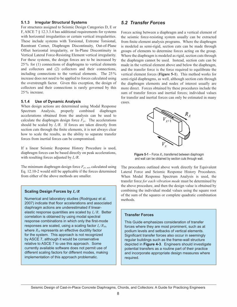
Figure 5-1 – Force RA transferred between diaphragm and wall can be obtained by section cuts through wall.
5.1.3 Irregular Structural SystemsFor structures assigned to Seismic Design Categories D, E or F, ASCE 7 § 12.3.3.4 has additional requirements for systems with horizontal irregularities or certain vertical irregularities. These include systems with Torsional, Extreme Torsional, Reentrant Corner, Diaphragm Discontinuity, Out-of-Plane Offset horizontal irregularity, or In-Plane Discontinuity in Vertical Lateral Force-Resisting Element vertical irregularity. For these systems, the design forces are to be increased by 25 % for (1) connections of diaphragms to vertical elements and collectors and (2) collectors and their connections, including connections to the vertical elements. The 25 % increase does not need to be applied to forces calculated using the overstrength factor. Given this exception, the design of collectors and their connections is rarely governed by this 25 % increase.
5.1.4 Use of Dynamic Analysis When design actions are determined using Modal Response Spectrum Analysis, properly combined diaphragm accelerations obtained from the analysis can be used to calculate the diaphragm design force Fpx. The accelerations should be scaled by Ie/R. If forces are taken directly from section cuts through the finite elements, it is not always clear how to scale the results, as the ability to separate transfer forces from inertial forces can be compromised.
If a linear Seismic Response History Procedure is used, diaphragm forces can be based directly on peak accelerations, with resulting forces adjusted by Ie/R.
The minimum diaphragm design force Fpx, min calculated using Eq. 12.10-2 would still be applicable if the forces determined from either of the above methods are smaller.
Scaling Design Forces by Ie /R
Numerical and laboratory studies (Rodriguez et al. 2007) indicate that floor accelerations and associated diaphragm actions are underestimated if linear-elastic response quantities are scaled by Ie/R. Better correlation is obtained by using modal spectral response combinations in which only the first-mode responses are scaled, using a scaling factor Ie/RM, where RM represents an effective ductility factor for the system. This approach is not recognized by ASCE 7, although it would be conservative relative to ASCE 7 to use this approach. Some currently available software does not permit use of different scaling factors for different modes, making implementation of this approach problematic.
5.2 Transfer Forces
Forces acting between a diaphragm and a vertical element of the seismic force-resisting system usually can be extracted from finite element analysis programs. Where the diaphragm is modeled as semi-rigid, section cuts can be made through groups of elements to determine forces acting on the group. Where the diaphragm is modeled as rigid, section cuts through the diaphragm cannot be used. Instead, section cuts can be made in the vertical element above and below the diaphragm, and the transfer force is the force required to equilibrate the vertical element forces (Figure 5-1). This method works for semi-rigid diaphragms, as well, although section cuts through the diaphragm elements and nodes of interest usually are more direct. Forces obtained by these procedures include the sum of transfer forces and inertial forces; individual values for transfer and inertial forces can only be estimated in many cases.
The procedures outlined above work directly for Equivalent Lateral Force and Seismic Response History Procedures. When Modal Response Spectrum Analysis is used, the transfer force for each vibration mode must be determined by the above procedure, and then the design value is obtained by combining the individual modal values using the square root of the sum of the squares or complete quadratic combination methods.
Transfer Forces
This Guide emphasizes consideration of transfer forces where they are most prominent, such as at podium levels and setbacks of vertical elements. Significant transfer forces also occur in seemingly regular buildings such as the frame-wall structure depicted in Figure 4-3. Engineers should investigate potential transfers as a routine part of their practice and incorporate appropriate design measures where required.
9Seismic Design of Cast-in-Place Concrete Diaphragms, Chords, and Collectors: A Guide for Practicing Engineers
5.3 Diaphragm Stiffness Modeling
ASCE 7 permits reinforced concrete diaphragms to be idealized as rigid in an analysis model if the span-to-depth ratio is less than or equal to 3 and if there are no horizontal irregularities as defined in ASCE 7 Table 12.3-1. In all other cases, the flexibility of the diaphragm must be modeled. By including diaphragm flexibility, the transfer of forces among diaphragms and vertical elements can be better estimated, especially at locations where large transfers occur.
The stiffness assumptions used for diaphragm modeling affect not only the forces within the diaphragm, but also the distribution of forces among the vertical elements. This is particularly true at levels with significant changes in mass or stiffness of the vertical elements, such as at podium levels or the initial below-grade levels of a high-rise structure. Stiffness reduction associated with diaphragm cracking commonly is approximated by applying a stiffness modifier to the diaphragm in-plane gross-section stiffness properties. Stiffness modifiers for reinforced concrete diaphragms commonly fall in the range of 0.15 to 0.50 when analyzing the building for design-level earthquake demands. See Nakaki (2000). In cases where the analysis results are sensitive to diaphragm stiffness assumptions, it may be prudent to “bound” the solution by analyzing the structure using both the lower and upper range of diaphragm stiffnesses, and selecting the design values as the largest forces from the two analyses.
5.4 Special Conditions
5.4.1 Diaphragms with OpeningsFor diaphragms with small openings (on the order of one or two diaphragm thicknesses for typical diaphragms), common practice is to place reinforcement on either side of the opening having area equal to the area of reinforcement disrupted by the opening, with no other special analysis. For a larger opening, the diaphragms must be designed to transfer the forces around the opening. Methods used to determine these forces range from simplified hand calculations as described in Section 6 to detailed finite element modeling.
In some cases, portions of the diaphragm experience axial stresses due to global behavior or due to local actions that occur around openings. If large axial stresses develop, then confinement reinforcement may be required (see Section 7).
5.4.2 Discontinuities in Vertical ElementsLarge diaphragm transfer forces can occur where vertical ele-ments of the seismic force-resisting system are discontinuous. Diaphragms must be designed to resist these transfer forces in addition to the inertial forces. As described in Section 5.3, semi-rigid diaphragms can be used in the building analysis model to track the transfer forces more accurately.
5.4.3 RampsRamps and sloping diaphragms can create unique design challenges, especially where they create a connection between different stories of a structure. In some cases, story shear can migrate out of the vertical elements of the seismic force-resisting system through the ramp in the form of shear or axial forces. This additional force should be considered in the design of sloping diaphragms. Engineering practice varies with respect to how to treat these conditions in an analysis model. Idealizing a sloping diaphragm as a flat, continuous element might not correctly identify such forces, and might lead to over-stating the stiffness of the diaphragm at a particular location. The potential implications of the modeling assumptions of ramps should be considered when determining whether or not to explicitly include sloping diaphragms in an analysis model. For additional guidance, see SEAOC (2009).
Ramps
Ramps that connect to multiple levels of a structure transfer lateral forces between the connected levels and can create unique design issues including the following:
For seismic forces parallel to a ramp, it acts as a strut between levels. For seismic forces perpendicular to a ramp, it acts as an inclined shear wall. In both cases, the force distribution to the vertical elements can be affected;
Short columns can be formed at the ends of a ramp, resulting in large shear forces that must be addressed;
Ramps often create flexible, disconnected diaphragm conditions that need to be addressed;
Where ramps terminate at a rigid foundation, lateral forces can bypass the vertical lateral system altogether;
Corkscrew ramp configurations sometimes cause an undesirable overall torsional response of the structure.
5.5 Displacement Compatibility for Flexible Diaphragms
Flexible diaphragms will experience in-plane displacements due to inertial loading in addition to the drift experienced by the vertical elements of the seismic force-resisting system. This
•
•
•
•
•
Seismic Design of Cast-in-Place Concrete Diaphragms, Chords, and Collectors: A Guide for Practicing Engineers
10
is discussed in ASCE 7 § 12.3. Components not designated as part of the seismic force-resisting system, such as gravity beams and columns, walls bending out-of-plane, slab-column and slab-wall connections, and cladding attachments should be evaluated for displacement compatibility based upon the additional displacement of the diaphragm. In some cases, it may be appropriate to include critical elements of the gravity system in the building lateral model to explicitly evaluate forces developed due to displacement compatibility.
Historical Perspective on Diaphragm Design
Prior to structural analysis software making finite element analysis of diaphragms readily available, diaphragm design was based on the simplifying assumption that the diaphragm was either completely flexible or infinitely rigid.
Flexible diaphragms were assumed to act as simply-supported beams spanning horizontally between the vertical elements of the seismic force-resisting system, without consideration of continuity across interior lines of resisting elements. Diaphragm chord forces were calculated by dividing the simple span moment by the diaphragm depth. Forces ‘tributary’ to the vertical elements were calculated as the sum of the simple span reactions to those elements.
With the rigid diaphragm assumption, distribution of lateral forces to the vertical elements was made based on their relative stiffness. This assumption was adopted in the first generation structural analysis programs to reduce the computational demand on memory and processor speed. The lateral forces calculated for the vertical members at each line could then be translated into shear forces to be distributed along the diaphragm at each line.
In some cases, depending on the diaphragm material, overall proportions, and relative stiffness of vertical and horizontal elements, it was unclear whether to assume flexible or rigid behavior. In such cases, designers often ‘enveloped’ the analysis considering results from both flexible and rigid analyses.
With currently available structural analysis software, flexibility of the diaphragm can be modeled directly wherever diaphragm flexibility is in question. Bounding analyses still are valuable to understand effects of uncertain stiffnesses on design quantities.
11Seismic Design of Cast-in-Place Concrete Diaphragms, Chords, and Collectors: A Guide for Practicing Engineers
6. Diaphragm Analysis Guidance 6.1 Diaphragm Modeling and Analysis Approaches
Internal forces in a diaphragm are computed using approaches that range from simple idealizations to complex computer analysis. The analysis need only be as complex as necessary to represent how lateral forces flow through the building including the diaphragms. For regular buildings in which lateral resistance is provided by similar vertical elements distributed throughout the floor plan, simple models are often adequate for determining the diaphragm forces. For buildings with irregularities or with dissimilar vertical elements, significant force transfers may occur among the vertical elements at various levels, requiring more complex models to determine the diaphragm design forces.
For smaller buildings with regular geometries, two lines of vertical elements in a given direction, and continuous vertical elements from foundation to roof, a simple model such as the equivalent beam model, provides adequate diaphragm demands. If three or more lines of vertical elements are present in a given direction and there are no major discontinuities in the vertical elements, the equivalent beam on springs model, which is slightly more complex than the equivalent beam model, may be appropriate to determine diaphragm demands. Another approach is to use the distribution of diaphragm inertial forces to vertical elements from a computer model and then implement the corrected equivalent beam model to determine the diaphragm demands.
In multi-story buildings with significant transfer of loads between vertical elements, it may be necessary to analyze a complete model of the building to adequately identify the force transfers. For such buildings it also may be advisable to model diaphragm flexibility, as flexibility may influence calculated transfers. Finally, any building with diaphragm discontinuities may require more complex models such as finite elements or strut-and-tie models.
Traditional Models versus Computer Analyses
The equivalent beam, equivalent beam-on-springs, and corrected equivalent beam models are traditional, approximate approaches that are still used extensively to design concrete diaphragms. They can be especially suitable for diaphragms in regions of low and moderate seismicity because force demands often are low relative to the inherent strength, such that more precise computation is unwarranted. In regions of high seismicity, where seismic demands commonly exceed inherent strength, computer analysis to determine diaphragm demands is increasingly common.
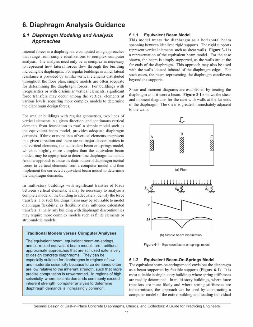
6.1.1 Equivalent Beam ModelThis model treats the diaphragm as a horizontal beam spanning between idealized rigid supports. The rigid supports represent vertical elements such as shear walls. Figure 3-1 is a representation of the equivalent beam model. For the case shown, the beam is simply supported, as the walls are at the far ends of the diaphragm. This approach may also be used with the walls located inboard of the diaphragm edges. For such cases, the beam representing the diaphragm cantilevers beyond the supports.
Shear and moment diagrams are established by treating the diaphragm as if it were a beam. Figure 3-1b shows the shear and moment diagrams for the case with walls at the far ends of the diaphragm. The shear is greatest immediately adjacent to the walls.
Figure 6-1 – Equivalent beam-on-springs model.
6.1.2 Equivalent Beam-On-Springs Model The equivalent beam-on-springs model envisions the diaphragm as a beam supported by flexible supports (Figure 6-1). It is most suitable in single-story buildings where spring stiffnesses are readily determined. In multi-story buildings, where force transfers are more likely and where spring stiffnesses are indeterminate, the approach can be used by constructing a computer model of the entire building and loading individual
(a) Plan
(b) Simple beam idealization

Seismic Design of Cast-in-Place Concrete Diaphragms, Chords, and Collectors: A Guide for Practicing Engineers
12
levels with the design diaphragm forces. The diaphragm may be treated either as a rigid beam or as a beam with flexural and shear stiffness properties.
6.1.3 Corrected Equivalent Beam ModelThe corrected equivalent beam model approximates diaphragm actions where there is significant interaction among vertical elements of the seismic force-resisting system. Such effects may occur where vertical elements of different stiffness interact or where vertical irregularities or building torsion occur. The basic approach is to identify the forces transferred between the diaphragm and each of the vertical elements, define a diaphragm lateral loading that is in equilibrium with these forces, and then analyze the diaphragm for this lateral loading. Where diaphragm flexibility is modeled in a computer analysis, the forces transferred to the diaphragm at a vertical element can be obtained by a section cut through the diaphragm around the vertical element. Where the diaphragm is modeled as rigid and the Equivalent Lateral Force Procedure is used, the forces transferred to the diaphragm can be calculated as the difference in forces in the vertical element above and below the diaphragm (Figure 5-1).
For smaller buildings without irregularities, the reactions may be determined using the direct inertial force, Fx (or Fpx), and accounting for torsion resulting from differences in the center of rigidity and the center of mass. Referring to Figure 6-2, the diaphragm forces to the vertical elements are computed as follows:
where Ri is the force acting between the diaphragm and vertical element i, Fx is the story force, kix is the stiffness of vertical element i in the x direction, ex is the perpendicular distance between the center of rigidity and the center of mass, ei is the perpendicular distance between the center of rigidity and the stiffness ki of vertical element i, and Jr is the polar moment of inertia computed as follows:
To approximate the actions within the diaphragm, the forces Ri acting between the diaphragm and the vertical elements in the direction under consideration are summed (in Figure 6-2, this would be RA + RB = Fx) and their centroid is determined. For a rectangular diaphragm of uniform mass, a trapezoidal distributed force having the same total force and centroid is then applied to the diaphragm. The resulting shears and moments (Figure 6-2b) are acceptable for diaphragm design. Note that this approach leaves any moment due to RC and RD
unresolved; sometimes this is ignored or, alternatively, it too can be incorporated in the trapezoidal loading.
6.1.4 Finite Element Model Finite element modeling of a diaphragm can be useful for assessing the force transfer among vertical elements, addressing force transfer around large openings, assessing the impact of ramps in parking garages, and designing irregularly-shaped diaphragms. Where vertical irregularities occur in the vertical elements of the seismic force-resisting system, rigid diaphragm models may produce force “spikes” that are unrealistic and difficult to design for. By modeling diaphragm flexibility at the level of irregularity and adjacent floors, more realistic transfer distributions can be obtained.
Figure 6-2 – Corrected equivalent beam model.
Significant force transfer often occurs at ground level slabs over one or more basements as shown in Figure 2-1 and 6-3. At these slabs, forces are distributed out of vertical elements such as shear walls and transferred through the diaphragm to the basement walls. The flexibility of the diaphragm will greatly reduce the force that is distributed out of the walls, thus reducing the backstay effect. It will also reduce the backstay effect, shown in Figure 6-3, of the shear walls extending below the ground level.
Figure 6-3 – The force couple resisting overturning in walls at the podium level and below is known as the backstay effect.
(a) Plan
(b) Simple beam idealization
13Seismic Design of Cast-in-Place Concrete Diaphragms, Chords, and Collectors: A Guide for Practicing Engineers
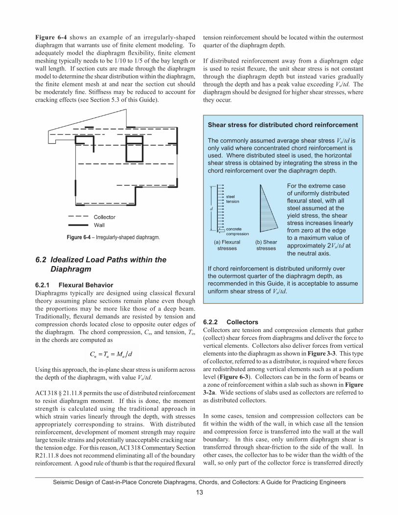
Figure 6-4 shows an example of an irregularly-shaped diaphragm that warrants use of finite element modeling. To adequately model the diaphragm flexibility, finite element meshing typically needs to be 1/10 to 1/5 of the bay length or wall length. If section cuts are made through the diaphragm model to determine the shear distribution within the diaphragm, the finite element mesh at and near the section cut should be moderately fine. Stiffness may be reduced to account for cracking effects (see Section 5.3 of this Guide).
Figure 6-4 – Irregularly-shaped diaphragm.
6.2 Idealized Load Paths within the Diaphragm
6.2.1 Flexural BehaviorDiaphragms typically are designed using classical flexural theory assuming plane sections remain plane even though the proportions may be more like those of a deep beam. Traditionally, flexural demands are resisted by tension and compression chords located close to opposite outer edges of the diaphragm. The chord compression, Cu, and tension, Tu, in the chords are computed as
Using this approach, the in-plane shear stress is uniform across the depth of the diaphragm, with value Vu/td.
ACI 318 § 21.11.8 permits the use of distributed reinforcement to resist diaphragm moment. If this is done, the moment strength is calculated using the traditional approach in which strain varies linearly through the depth, with stresses appropriately corresponding to strains. With distributed reinforcement, development of moment strength may require large tensile strains and potentially unacceptable cracking near the tension edge. For this reason, ACI 318 Commentary Section R21.11.8 does not recommend eliminating all of the boundary reinforcement. A good rule of thumb is that the required flexural
tension reinforcement should be located within the outermost quarter of the diaphragm depth.
If distributed reinforcement away from a diaphragm edge is used to resist flexure, the unit shear stress is not constant through the diaphragm depth but instead varies gradually through the depth and has a peak value exceeding Vu/td. The diaphragm should be designed for higher shear stresses, where they occur.
Shear stress for distributed chord reinforcement
The commonly assumed average shear stress Vu/td is only valid where concentrated chord reinforcement is used. Where distributed steel is used, the horizontal shear stress is obtained by integrating the stress in the chord reinforcement over the diaphragm depth.
For the extreme case of uniformly distributed flexural steel, with all steel assumed at the yield stress, the shear stress increases linearly from zero at the edge to a maximum value of approximately 2Vu/td at the neutral axis.
If chord reinforcement is distributed uniformly over the outermost quarter of the diaphragm depth, as recommended in this Guide, it is acceptable to assume uniform shear stress of Vu/td.
6.2.2 CollectorsCollectors are tension and compression elements that gather (collect) shear forces from diaphragms and deliver the force to vertical elements. Collectors also deliver forces from vertical elements into the diaphragm as shown in Figure 3-3. This type of collector, referred to as a distributor, is required where forces are redistributed among vertical elements such as at a podium level (Figure 6-3). Collectors can be in the form of beams or a zone of reinforcement within a slab such as shown in Figure 3-2a. Wide sections of slabs used as collectors are referred to as distributed collectors.
In some cases, tension and compression collectors can be fit within the width of the wall, in which case all the tension and compression force is transferred into the wall at the wall boundary. In this case, only uniform diaphragm shear is transferred through shear-friction to the side of the wall. In other cases, the collector has to be wider than the width of the wall, so only part of the collector force is transferred directly
(a) Flexural stresses
(b) Shear stresses
Seismic Design of Cast-in-Place Concrete Diaphragms, Chords, and Collectors: A Guide for Practicing Engineers
14
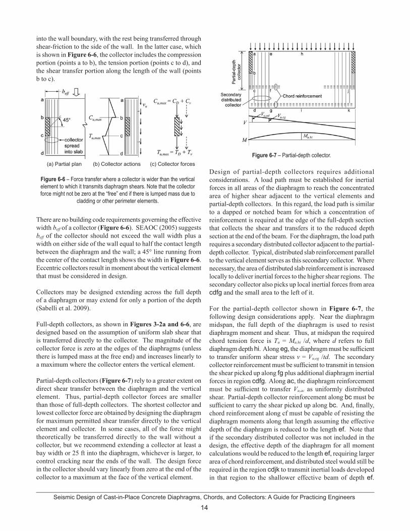
into the wall boundary, with the rest being transferred through shear-friction to the side of the wall. In the latter case, which is shown in Figure 6-6, the collector includes the compression portion (points a to b), the tension portion (points c to d), and the shear transfer portion along the length of the wall (points b to c).
Figure 6-6 – Force transfer where a collector is wider than the vertical element to which it transmits diaphragm shears. Note that the collector force might not be zero at the “free” end if there is lumped mass due to
cladding or other perimeter elements.
There are no building code requirements governing the effective width beff of a collector (Figure 6-6). SEAOC (2005) suggests beff of the collector should not exceed the wall width plus a width on either side of the wall equal to half the contact length between the diaphragm and the wall; a 45° line running from the center of the contact length shows the width in Figure 6-6. Eccentric collectors result in moment about the vertical element that must be considered in design.
Collectors may be designed extending across the full depth of a diaphragm or may extend for only a portion of the depth (Sabelli et al. 2009).
Full-depth collectors, as shown in Figures 3-2a and 6-6, are designed based on the assumption of uniform slab shear that is transferred directly to the collector. The magnitude of the collector force is zero at the edges of the diaphragms (unless there is lumped mass at the free end) and increases linearly to a maximum where the collector enters the vertical element.
Partial-depth collectors (Figure 6-7) rely to a greater extent on direct shear transfer between the diaphragm and the vertical element. Thus, partial-depth collector forces are smaller than those of full-depth collectors. The shortest collector and lowest collector force are obtained by designing the diaphragm for maximum permitted shear transfer directly to the vertical element and collector. In some cases, all of the force might theoretically be transferred directly to the wall without a collector, but we recommend extending a collector at least a bay width or 25 ft into the diaphragm, whichever is larger, to control cracking near the ends of the wall. The design force in the collector should vary linearly from zero at the end of the collector to a maximum at the face of the vertical element.
Figure 6-7 – Partial-depth collector.
Design of partial-depth collectors requires additional considerations. A load path must be established for inertial forces in all areas of the diaphragm to reach the concentrated area of higher shear adjacent to the vertical elements and partial-depth collectors. In this regard, the load path is similar to a dapped or notched beam for which a concentration of reinforcement is required at the edge of the full-depth section that collects the shear and transfers it to the reduced depth section at the end of the beam. For the diaphragm, the load path requires a secondary distributed collector adjacent to the partial-depth collector. Typical, distributed slab reinforcement parallel to the vertical element serves as this secondary collector. Where necessary, the area of distributed slab reinforcement is increased locally to deliver inertial forces to the higher shear regions. The secondary collector also picks up local inertial forces from area cdfg and the small area to the left of it.
For the partial-depth collector shown in Figure 6-7, the following design considerations apply. Near the diaphragm midspan, the full depth of the diaphragm is used to resist diaphragm moment and shear. Thus, at midspan the required chord tension force is Tu = Mu,hi /d, where d refers to full diaphragm depth hi. Along eg, the diaphragm must be sufficient to transfer uniform shear stress v = Vu,eg /td. The secondary collector reinforcement must be sufficient to transmit in tension the shear picked up along fg plus additional diaphragm inertial forces in region cdfg. Along ac, the diaphragm reinforcement must be sufficient to transfer Vu,ac as uniformly distributed shear. Partial-depth collector reinforcement along bc must be sufficient to carry the shear picked up along bc. And, finally, chord reinforcement along cf must be capable of resisting the diaphragm moments along that length assuming the effective depth of the diaphragm is reduced to the length ef. Note that if the secondary distributed collector was not included in the design, the effective depth of the diaphragm for all moment calculations would be reduced to the length ef, requiring larger area of chord reinforcement, and distributed steel would still be required in the region cdjk to transmit inertial loads developed in that region to the shallower effective beam of depth ef.
(a) Partial plan (b) Collector actions (c) Collector forces

15Seismic Design of Cast-in-Place Concrete Diaphragms, Chords, and Collectors: A Guide for Practicing Engineers
Treating the diaphragm as a shallower beam of depth ef also could result in large cracks forming at the extreme tension edge of the diaphragm as it is flexed under lateral load.
6.2.3 Diaphragm-to-Vertical-Element Force Transfer
Diaphragm shear is transferred to vertical elements by the collectors and by shear-friction between the diaphragm and the vertical element. Where collector bars enter a vertical element such as a wall, the force is directly transferred to the wall. However, the collector must extend into the vertical element a distance that is typically much longer than a collector bar development length. Collectors that extend through the entire length of a vertical element ensure that force is transferred from the collector to the element without further consideration. Transfer of collector tension force to a wall is analogous to loading a concrete beam near its bottom and providing hanger reinforcement to transfer the load to the top of the beam. Collector bars must extend deeply enough into the vertical element to transfer the force to bars in the vertical element as shown in Figure 6-8. In the figure, the collector force is transferred to typical horizontal wall reinforcement that in turn distributes the collector force to the full length of the wall. This typical horizontal wall reinforcement must not only transfer the collector force but also must resist wall design shear; thus, the horizontal wall steel is the sum of reinforcement required for the collector force and the reinforcement required for the shear in the wall above the level of the collector.
Figure 6-8 – Transfer of collector force directly to shear wall.
If the collector is wider than the vertical element such as shown in Figure 6-6, portions of the collector force, CD and TD, are transferred directly to the ends of walls and the remaining portions of the collector force, Cv and Tv, are transferred to the vertical element by shear-friction along the length of the vertical element. This portion of the collector force is represented in Figure 6-6c by the force along the length of the wall. The design shear-friction force is the combination of the collector force along the vertical element, which is amplified by the
overstrength factor, Ωo, and the direct diaphragm shear force, Vu, along the length of the vertical element. Slab reinforcement perpendicular to the vertical element is typically added to serve as this shear-friction reinforcement.
6.2.4 Strut-and-tie ModelStrut-and-tie models may be used to distribute the flow of force through a diaphragm. Such models have not been used extensively for overall design of diaphragms, though sometimes they can be useful for this purpose. Instead, strut-and-tie models are more often used to identify force paths and reinforcement layouts around discontinuities. Where used, distributed reinforcement of at least 0.0025 times the gross slab area should be provided in each direction to control cracking.
Figure 6-9 illustrates how strut-and-tie models can be used to understand required reinforcement layouts. In this example, force from a structural wall is transferred around an opening through a distributor, into a diaphragm, and into nearby basement walls. The force transfer in the diaphragm can be visualized as occurring through compression struts acting at an angle between about 30° and 60° relative to the wall force. Considering abcd as a free body diagram, moment equilibrium about d requires tension tie bc, which must be developed into the adjacent diaphragm segment. Moment equilibrium about c cannot be provided by a tension tie from a to d because the tension tie would have to be anchored to the basement wall out of plane, which is inappropriate. Instead, moment equilibrium about c is provided by a compressive force from the adjacent diaphragm segment at a. Force reversal as occurs during earthquakes would reverse the diagonal compression struts and require tension ties ad and eh (not shown). Section 7 provides additional discussion on how to detail the required reinforcement.
Figure 6-9 – Strut-and-tie model at force transfer to basement wall.
6.2.5 Large OpeningsDesign of a diaphragm with a large opening is analogous to design of a beam with opening. Consider the opening in Figure 6-10. One approach is to assume the reinforcement labeled Lredistributes uniform shear left of the opening to the portions of the diaphragm above and below the opening in proportion to
Seismic Design of Cast-in-Place Concrete Diaphragms, Chords, and Collectors: A Guide for Practicing Engineers
16
their relative stiffness. The reinforcement labeled R distributes the shear from above and below the opening to a uniform shear to the right of the opening. The reinforcement labeled T and B resists the local moment within the section above and below the opening. This moment is sometimes approximated as VTl/2 and VBl/2, which is correct if the inflection point is at the center of the length of the opening. It is prudent to assume that the inflection point may vary, which will increase the moment. If a finite element analysis is being used, section cuts can be used to determine the forces and a hand analysis approach such as the one described can be used as a tool to check the results.
Figure 6-10 – Diaphragms with large openings.
6.3 Diaphragm Slabs-on-ground
For some structures, slabs-on-ground are used as diaphragms to tie together and distribute forces among vertical elements and foundation elements. This is done where the foundation supporting a vertical element does not have adequate soil friction and passive bearing strength to resist design horizontal load on its own. The slab-on-ground diaphragm redistributes some of the horizontal load to locations where additional resistance to sliding is obtained. Friction below the slab-on-ground diaphragm and below other foundation elements, as well as the passive bearing acting on these other foundation elements, provide the added resistance to sliding.
Slabs-on-grade that serve as diaphragms are considered structural slabs. Structural slabs are required to be designed in accordance with ACI 318. Although these slabs typically do not need to be reinforced for flexure caused by loads on the surface of the slab, they must be reinforced for the in-plane shear and flexure. These slabs must also meet the minimum reinforcement requirements for a structural slab.
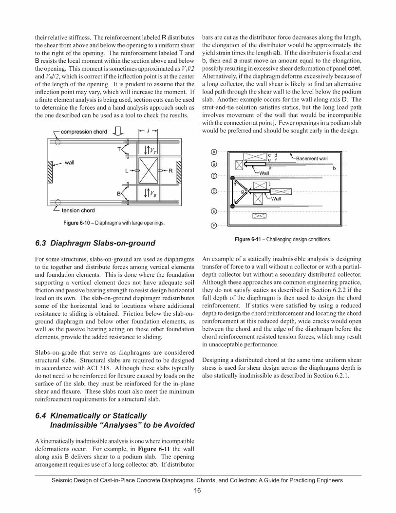
6.4 Kinematically or Statically Inadmissible “Analyses” to be Avoided
A kinematically inadmissible analysis is one where incompatible deformations occur. For example, in Figure 6-11 the wall along axis B delivers shear to a podium slab. The opening arrangement requires use of a long collector ab. If distributor
bars are cut as the distributor force decreases along the length, the elongation of the distributor would be approximately the yield strain times the length ab. If the distributor is fixed at end b, then end a must move an amount equal to the elongation, possibly resulting in excessive shear deformation of panel cdef. Alternatively, if the diaphragm deforms excessively because of a long collector, the wall shear is likely to find an alternative load path through the shear wall to the level below the podium slab. Another example occurs for the wall along axis D. The strut-and-tie solution satisfies statics, but the long load path involves movement of the wall that would be incompatible with the connection at point j. Fewer openings in a podium slab would be preferred and should be sought early in the design.
Figure 6-11 – Challenging design conditions.
An example of a statically inadmissible analysis is designing transfer of force to a wall without a collector or with a partial-depth collector but without a secondary distributed collector. Although these approaches are common engineering practice, they do not satisfy statics as described in Section 6.2.2 if the full depth of the diaphragm is then used to design the chord reinforcement. If statics were satisfied by using a reduced depth to design the chord reinforcement and locating the chord reinforcement at this reduced depth, wide cracks would open between the chord and the edge of the diaphragm before the chord reinforcement resisted tension forces, which may result in unacceptable performance.
Designing a distributed chord at the same time uniform shear stress is used for shear design across the diaphragms depth is also statically inadmissible as described in Section 6.2.1.
17Seismic Design of Cast-in-Place Concrete Diaphragms, Chords, and Collectors: A Guide for Practicing Engineers
7. Design Guidance 7.1 Load and Resistance Factors
ASCE 7 § 12 defines the load combinations applicable to diaphragm and collector design. The load combinations require horizontal seismic effects to be evaluated in conjunction with vertical seismic effects, dead load, variable portions of the live load, and other applied loads such as soil pressures, snow, and fluids. The vertical seismic effect, Ev, is defined per Eq. 12.4-4 as 0.2SDS. Ev can increase or decrease the dead load effect.
The basic load combinations for strength design of reinforced concrete diaphragms and collectors are:
When load combinations with overstrength factor are required to be used, the strength design equations become:
In general, diaphragms and collectors are permitted to be designed for seismic forces applied independently in each of the two orthogonal directions. For structures assigned to Seismic Design Categories C through F and having non-parallel systems or plan irregularity type 5, however, diaphragm design must consider the interaction of orthogonal loading in one of two ways. If the Equivalent Lateral Force Procedure or Modal Response Spectrum Analyses are used, 100 % of the effects in one primary direction are to be combined with 30 % of the effects in the other direction. If a response-history analysis is performed in accordance with ASCE 7 § 16.1 or 16.2, orthogonal pairs of ground motion histories are to be applied simultaneously.
Though not required by ASCE 7, common practice is to consider the orthogonal combination for all diaphragm and collector design. This Guide adopts that approach.
For structures that resist earthquake effects using intermediate precast structural walls in Seismic Design Categories D, E, or F, or special moment frames or special structural walls in any Seismic Design Category, f for shear is 0.6 if the nominal shear strength is less than the shear corresponding to the flexural strength of the diaphragm. In addition, the strength reduction factor for shear may not exceed the minimum reduction factor for shear used for the vertical components of the seismic force-resisting system.
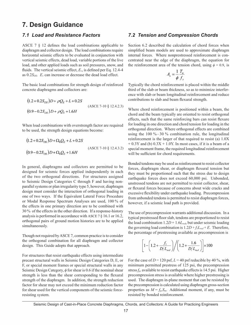
7.2 Tension and Compression Chords
Section 6.2 described the calculation of chord forces when simplified beam models are used to approximate diaphragm internal forces. Where nonprestressed reinforcement is con-centrated near the edge of the diaphragm, the equation for the reinforcement area of the tension chord, using f = 0.9, is
Typically the chord reinforcement is placed within the middle third of the slab or beam thickness, so as to minimize interfer-ence with slab or beam longitudinal reinforcement and reduce contributions to slab and beam flexural strength.
Where chord reinforcement is positioned within a beam, the chord and the beam typically are oriented to resist orthogonal effects, such that the same reinforcing bars can resist flexure for loading in one direction and chord tension for loading in the orthogonal direction. Where orthogonal effects are combined using the 100 %–30 % combination rule, the longitudinal reinforcement is the larger of that required to resist (a) 1.0X + 0.3Y and (b) 0.3X + 1.0Y. In most cases, if it is a beam of a special moment frame, the required longitudinal reinforcement will be sufficient for chord requirements.
Bonded tendons may be used as reinforcement to resist collector forces, diaphragm shear, or diaphragm flexural tension but they must be proportioned such that the stress due to design earthquake forces does not exceed 60,000 psi. Unbonded, unstressed tendons are not permitted to resist collector, shear, or flexural forces because of concerns about wide cracks and excessive flexibility under earthquake loading. Precompression from unbonded tendons is permitted to resist diaphragm forces, however, if a seismic load path is provided.
The use of precompression warrants additional discussion. In a typical prestressed floor slab, tendons are proportioned to resist the load combination 1.2D + 1.6Lred, but under seismic loading the governing load combination is 1.2D + f1Lred + E. Therefore, the percentage of prestressing available as precompression is
For the case of D = 120 psf, L = 40 psf reducible by 40 %, with minimum permitted prestress of 125 psi, the precompression stress fpc available to resist earthquake effects is 14.5 psi. Higher precompression stress is available where higher prestressing is used. The diaphragm in-plane moment that can be resisted by the precompression is calculated using diaphragm gross-section properties as M = fpcSm. Additional moment, if any, must be resisted by bonded reinforcement.
(ASCE 7-10 § 12.4.2.3)
(ASCE 7-10 § 12.4.3.2)
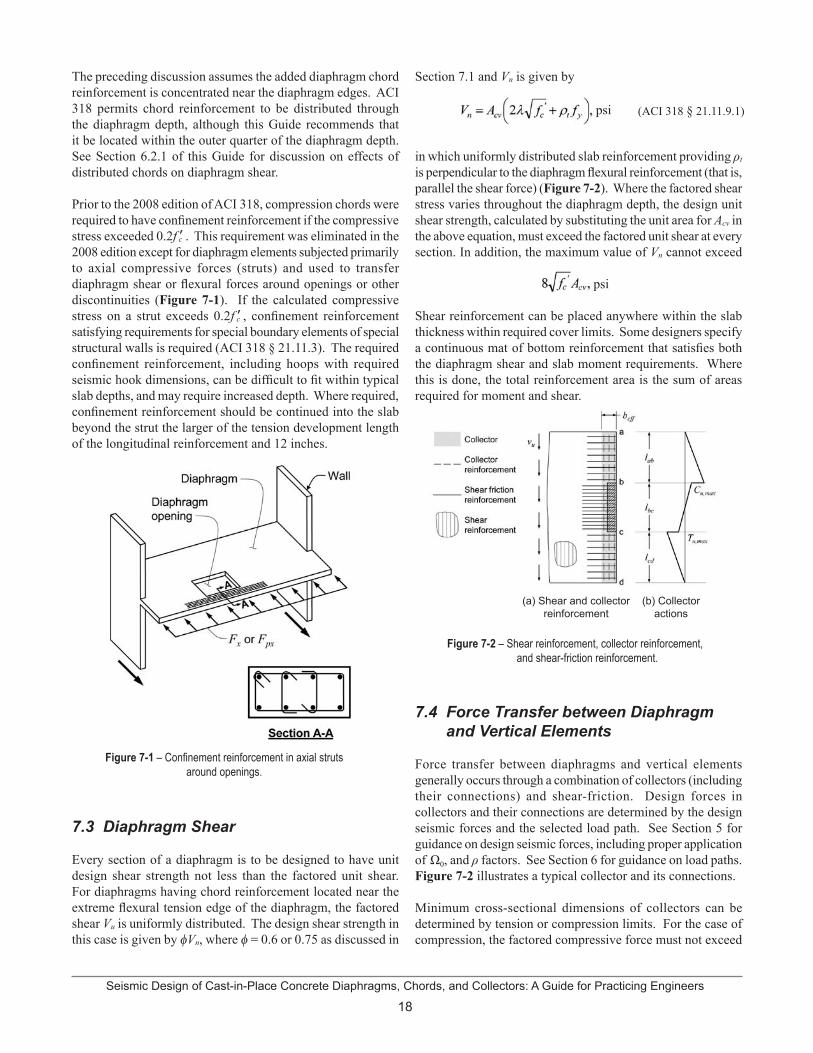
Seismic Design of Cast-in-Place Concrete Diaphragms, Chords, and Collectors: A Guide for Practicing Engineers
18
The preceding discussion assumes the added diaphragm chord reinforcement is concentrated near the diaphragm edges. ACI 318 permits chord reinforcement to be distributed through the diaphragm depth, although this Guide recommends that it be located within the outer quarter of the diaphragm depth. See Section 6.2.1 of this Guide for discussion on effects of distributed chords on diaphragm shear.
Prior to the 2008 edition of ACI 318, compression chords were required to have confinement reinforcement if the compressive stress exceeded 0.2f ’c . This requirement was eliminated in the 2008 edition except for diaphragm elements subjected primarily to axial compressive forces (struts) and used to transfer diaphragm shear or flexural forces around openings or other discontinuities (Figure 7-1). If the calculated compressive stress on a strut exceeds 0.2f ’c , confinement reinforcement satisfying requirements for special boundary elements of special structural walls is required (ACI 318 § 21.11.3). The required confinement reinforcement, including hoops with required seismic hook dimensions, can be difficult to fit within typical slab depths, and may require increased depth. Where required, confinement reinforcement should be continued into the slab beyond the strut the larger of the tension development length of the longitudinal reinforcement and 12 inches.
Figure 7-1 – Confinement reinforcement in axial struts around openings.
7.3 Diaphragm Shear
Every section of a diaphragm is to be designed to have unit design shear strength not less than the factored unit shear. For diaphragms having chord reinforcement located near the extreme flexural tension edge of the diaphragm, the factored shear Vu is uniformly distributed. The design shear strength in this case is given by fVn, where f = 0.6 or 0.75 as discussed in
Section 7.1 and Vn is given by
in which uniformly distributed slab reinforcement providing ρt
is perpendicular to the diaphragm flexural reinforcement (that is, parallel the shear force) (Figure 7-2). Where the factored shear stress varies throughout the diaphragm depth, the design unit shear strength, calculated by substituting the unit area for Acv in the above equation, must exceed the factored unit shear at every section. In addition, the maximum value of Vn cannot exceed
psi
Shear reinforcement can be placed anywhere within the slab thickness within required cover limits. Some designers specify a continuous mat of bottom reinforcement that satisfies both the diaphragm shear and slab moment requirements. Where this is done, the total reinforcement area is the sum of areas required for moment and shear.
Figure 7-2 – Shear reinforcement, collector reinforcement, and shear-friction reinforcement.
7.4 Force Transfer between Diaphragm and Vertical Elements
Force transfer between diaphragms and vertical elements generally occurs through a combination of collectors (including their connections) and shear-friction. Design forces in collectors and their connections are determined by the design seismic forces and the selected load path. See Section 5 for guidance on design seismic forces, including proper application of Ω0, and ρ factors. See Section 6 for guidance on load paths. Figure 7-2 illustrates a typical collector and its connections.
Minimum cross-sectional dimensions of collectors can be determined by tension or compression limits. For the case of compression, the factored compressive force must not exceed
(ACI 318 § 21.11.9.1) psi
(a) Shear and collector reinforcement
(b) Collector actions
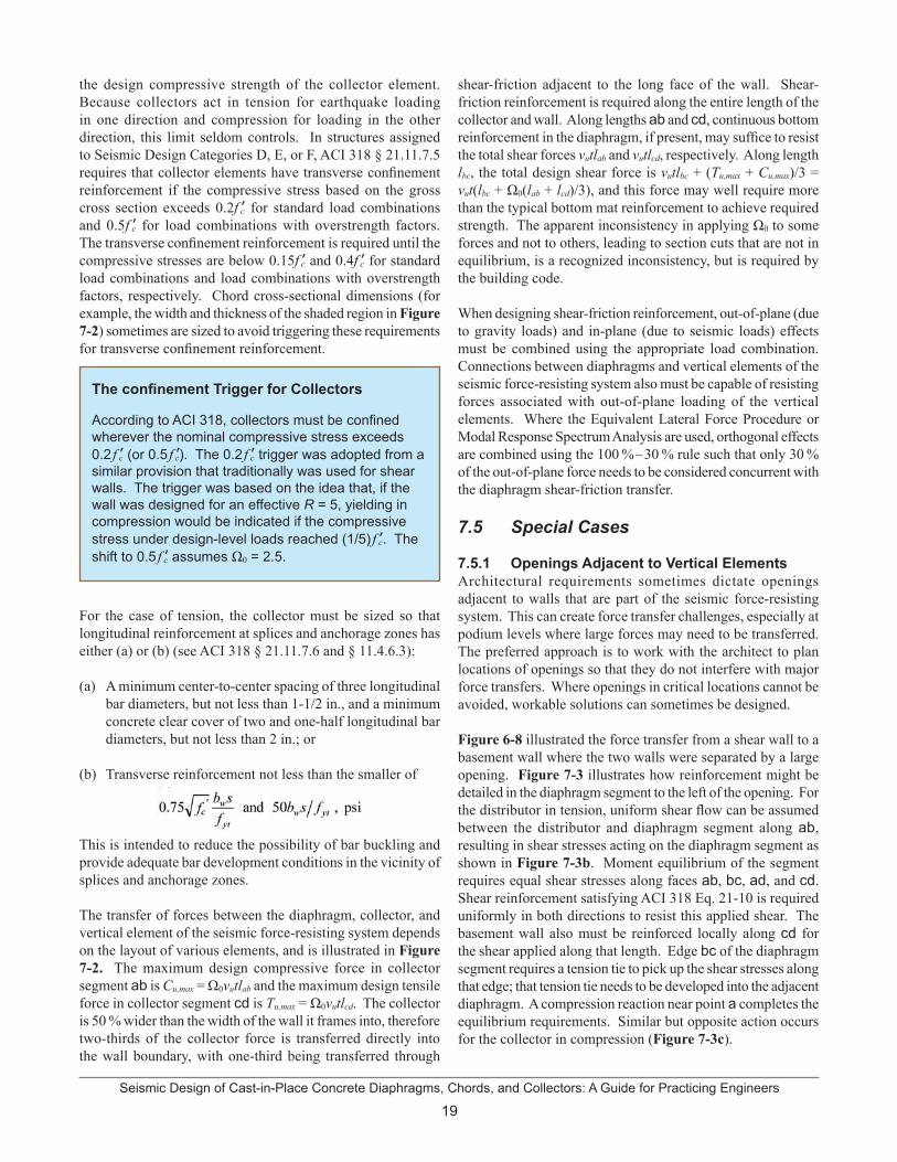
19Seismic Design of Cast-in-Place Concrete Diaphragms, Chords, and Collectors: A Guide for Practicing Engineers
the design compressive strength of the collector element. Because collectors act in tension for earthquake loading in one direction and compression for loading in the other direction, this limit seldom controls. In structures assigned to Seismic Design Categories D, E, or F, ACI 318 § 21.11.7.5 requires that collector elements have transverse confinement reinforcement if the compressive stress based on the gross cross section exceeds 0.2f ’c for standard load combinations and 0.5f ’c for load combinations with overstrength factors. The transverse confinement reinforcement is required until the compressive stresses are below 0.15f ’c and 0.4f ’c for standard load combinations and load combinations with overstrength factors, respectively. Chord cross-sectional dimensions (for example, the width and thickness of the shaded region in Figure 7-2) sometimes are sized to avoid triggering these requirements for transverse confinement reinforcement.
The confinement Trigger for Collectors
According to ACI 318, collectors must be confined wherever the nominal compressive stress exceeds 0.2 f ’c (or 0.5 f ’c). The 0.2 f ’c trigger was adopted from a similar provision that traditionally was used for shear walls. The trigger was based on the idea that, if the wall was designed for an effective R = 5, yielding in compression would be indicated if the compressive stress under design-level loads reached (1/5) f ’c. The shift to 0.5 f ’c assumes Ω0 = 2.5.
For the case of tension, the collector must be sized so that longitudinal reinforcement at splices and anchorage zones has either (a) or (b) (see ACI 318 § 21.11.7.6 and § 11.4.6.3):
A minimum center-to-center spacing of three longitudinal bar diameters, but not less than 1-1/2 in., and a minimum concrete clear cover of two and one-half longitudinal bar diameters, but not less than 2 in.; or
Transverse reinforcement not less than the smaller of
This is intended to reduce the possibility of bar buckling and provide adequate bar development conditions in the vicinity of splices and anchorage zones.
The transfer of forces between the diaphragm, collector, and vertical element of the seismic force-resisting system depends on the layout of various elements, and is illustrated in Figure 7-2. The maximum design compressive force in collector segment ab is Cu,max = Ω0vutlab and the maximum design tensile force in collector segment cd is Tu,max = Ω0vutlcd. The collector is 50 % wider than the width of the wall it frames into, therefore two-thirds of the collector force is transferred directly into the wall boundary, with one-third being transferred through
shear-friction adjacent to the long face of the wall. Shear-friction reinforcement is required along the entire length of the collector and wall. Along lengths ab and cd, continuous bottom reinforcement in the diaphragm, if present, may suffice to resist the total shear forces vutlab and vutlcd, respectively. Along length lbc, the total design shear force is vutlbc + (Tu,max + Cu,max)/3 = vut(lbc + Ω0(lab + lcd)/3), and this force may well require more than the typical bottom mat reinforcement to achieve required strength. The apparent inconsistency in applying Ω0 to some forces and not to others, leading to section cuts that are not in equilibrium, is a recognized inconsistency, but is required by the building code.
When designing shear-friction reinforcement, out-of-plane (due to gravity loads) and in-plane (due to seismic loads) effects must be combined using the appropriate load combination. Connections between diaphragms and vertical elements of the seismic force-resisting system also must be capable of resisting forces associated with out-of-plane loading of the vertical elements. Where the Equivalent Lateral Force Procedure or Modal Response Spectrum Analysis are used, orthogonal effects are combined using the 100 %–30 % rule such that only 30 % of the out-of-plane force needs to be considered concurrent with the diaphragm shear-friction transfer.
7.5 Special Cases
7.5.1 Openings Adjacent to Vertical ElementsArchitectural requirements sometimes dictate openings adjacent to walls that are part of the seismic force-resisting system. This can create force transfer challenges, especially at podium levels where large forces may need to be transferred. The preferred approach is to work with the architect to plan locations of openings so that they do not interfere with major force transfers. Where openings in critical locations cannot be avoided, workable solutions can sometimes be designed.
Figure 6-8 illustrated the force transfer from a shear wall to a basement wall where the two walls were separated by a large opening. Figure 7-3 illustrates how reinforcement might be detailed in the diaphragm segment to the left of the opening. For the distributor in tension, uniform shear flow can be assumed between the distributor and diaphragm segment along ab, resulting in shear stresses acting on the diaphragm segment as shown in Figure 7-3b. Moment equilibrium of the segment requires equal shear stresses along faces ab, bc, ad, and cd. Shear reinforcement satisfying ACI 318 Eq. 21-10 is required uniformly in both directions to resist this applied shear. The basement wall also must be reinforced locally along cd for the shear applied along that length. Edge bc of the diaphragm segment requires a tension tie to pick up the shear stresses along that edge; that tension tie needs to be developed into the adjacent diaphragm. A compression reaction near point a completes the equilibrium requirements. Similar but opposite action occurs for the collector in compression (Figure 7-3c).
(a)
(b)
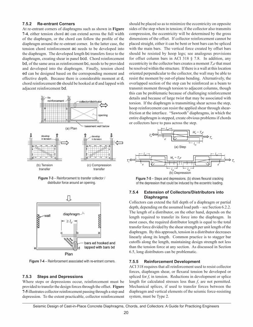
Seismic Design of Cast-in-Place Concrete Diaphragms, Chords, and Collectors: A Guide for Practicing Engineers
20
7.5.2 Re-entrant Corners At re-entrant corners of diaphragms such as shown in Figure 7-4, either tension chord ac can extend across the full width of the diaphragm, or the chord can follow the profile of the diaphragm around the re-entrant corner. In the latter case, the tension chord reinforcement ac needs to be developed into the diaphragm. The developed length bc transfers force to the diaphragm, creating shear in panel bcd. Chord reinforcement bd, of the same area as reinforcement bc, needs to be provided and developed into the diaphragm. Finally, tension chord ed can be designed based on the corresponding moment and effective depth. Because there is considerable moment at d, chord reinforcement de should be hooked at d and lapped with adjacent reinforcement bd.
Figure 7-3 – Reinforcement to transfer collector /distributor force around an opening.
7.5.3 Steps and DepressionsWhere steps or depressions occur, reinforcement must be provided to transfer the design forces through the offset. Figure 7-5 illustrates collector reinforcement passing through a step and depression. To the extent practicable, collector reinforcement
Figure 7-4 – Reinforcement associated with re-entrant corners.
should be placed so as to minimize the eccentricity on opposite sides of the step when in tension; if the collector also transmits compression, the eccentricity will be determined by the gross dimensions of the offset. If collector reinforcement cannot be placed straight, either it can be bent or bent bars can be spliced with the main bars. The vertical force created by offset bars should be resisted by hoop legs; see analogous provisions for offset column bars in ACI 318 § 7.8. In addition, any eccentricity in the collector bars creates a moment Tue that must be resolved within the structure. If there is a wall at this location oriented perpendicular to the collector, the wall may be able to resist the moment by out-of-plane bending. Alternatively, the overlapped section of the step can be reinforced as a beam to transmit moment through torsion to adjacent columns, though this can be problematic because of challenging reinforcement details and because of large twist that may be associated with torsion. If the diaphragm is transmitting shear across the step, hoop reinforcement can resist the applied shear through shear-friction at the interface. “Sawtooth” diaphragms, in which the entire diaphragm is stepped, create obvious problems if chords or collectors have to pass across the step.
Figure 7-5 – Steps and depressions. (b) shows flexural cracking of the depression that could be induced by the eccentric loading.
7.5.4 Extension of Collectors/Distributors into Diaphragms
Collectors can extend the full depth of a diaphragm or partial depth, depending on the assumed load path – see Section 6.2.2. The length of a distributor, on the other hand, depends on the length required to transfer its force into the diaphragm. In most cases, the required distributor length is equal to the total transfer force divided by the shear strength per unit length of the diaphragm. By this approach, tension in a distributor decreases linearly along its length. Common practice is to stagger bar cutoffs along the length, maintaining design strength not less than the tension force at any section. As discussed in Section 6.5, long distributors can be problematic.
7.5.5 Reinforcement DevelopmentACI 318 requires that all reinforcement used to resist collector forces, diaphragm shear, or flexural tension be developed or spliced for fy in tension. Reductions in development or splice length for calculated stresses less than fy are not permitted. Mechanical splices, if used to transfer forces between the diaphragm and vertical elements of the seismic force-resisting system, must be Type 2.
(a) Plan
(b) Tension transfer
(c) Compression transfer
(a) Step
(b) Depression

21Seismic Design of Cast-in-Place Concrete Diaphragms, Chords, and Collectors: A Guide for Practicing Engineers
8. Additional Requirements 8.1 Materials Properties
ACI 318 § 1.1.1 requires minimum specified compressive strength, f ’c, of 2500 psi for structural concrete including diaphragms, although f ’c at least 3000 psi is recommended here. Where diaphragms are cast monolithically with portions of special moment frames or shear walls for a structure assigned to Seismic Design Category D, E, or F, the minimum f ’c is 3000 psi (ACI 318 § 21.1.4) for that part of the diaphragm. This is typically not an issue as f ’c of 4000 to 6000 psi is commonly specified for floor systems.
For some structures, specified concrete strength of moment frame columns or shear walls is higher than that of the diaphragm/floor system. ACI 318 § 10.12, which allows column concrete compressive strength to be 1.4 times that of the floor system, is intended to apply only for axial load transmission and therefore should not be applied to walls or columns of the seismic force-resisting system. Many walls or moment frame columns are located along edges of the building slab or along openings, where the concrete is not confined by adjacent concrete on all sides. Additionally, these elements have high shear stress that must be transferred through the floor, requiring the higher strength.
For shear walls, the higher wall strength can be maintained using a jump core or flying form system for the wall construction to precede the floor construction. Where concrete for the portion of the wall or moment frame through the thickness of the floor system is placed with concrete for the floor system, the higher strength concrete should be puddled at these elements and extended 2 ft into the slab as allowed for columns in ACI 318 § 10.12.1 and described in commentary section R10.12.1.
Where lightweight concrete is used, the provisions of ACI 318 § 21.1.4.3 apply if the diaphragm concrete is also part of a special moment frame or special shear wall.
According to ACI 318 § 11.4.2 the values of fy and fyt used in design of reinforcement resisting shear shall not exceed 60,000 psi, except the value shall not exceed 80,000 psi for welded deformed wire reinforcement. The intent of the code requirement is to limit the width of shear cracks.
Reinforcement for chords and collectors is limited by the general requirements for bonded reinforcement of ACI 318 § 3.5.3, with two exceptions.
Where chord or collector reinforcement is placed within beams including the effective flange of special moment frames, and therefore acts as beam flexural reinforcement, the chord or collector reinforcement must satisfy ACI 318 § 21.1.5.2, that is, the reinforcement shall comply with ASTM A706 or equivalent.
ACI 318 § 21.11.7.2 limits the stress from design earthquake forces to 60,000 psi for bonded tendons. Although stress in other collector and chord reinforcement is not limited, consideration should be given to deformation compatibility between tension chords, collectors, and the floor slab. High tensile stress and strains in collectors and chords can result in excessive cracking that will migrate into the slab.
8.2 Inspection
Reinforced concrete diaphragms and their chords and collectors are a part of the seismic force-resisting system. Proper construction of diaphragms and their elements is paramount to ensuring that the structure will perform as intended during a major earthquake.
In an effort to ensure proper construction, special inspections are required for most concrete buildings. The IBC requires that the design professional for a building prepare a statement of special inspections identifying the required inspections for construction of the building. The statement is to include inspection requirements for seismic force-resisting systems in structures assigned to Seismic Design Categories C, D, E, or F. Diaphragms and their elements provide resistance to prescribed seismic forces; therefore, diaphragms are part of the seismic force-resisting system and should be identified on the statement of special inspections. Refer to the IBC for current requirements.
In accordance with IBC Table 1704.4, the size and placement of reinforcing steel, including prestressing tendons, must be verified with periodic inspections. Periodic inspection is intended to include inspection of all completed reinforcing steel placement, including diaphragm steel.
Concrete for diaphragms also requires special inspections. These special inspections often include the following from Table 1704.4:
Verifying use of required design mix.Sampling fresh concrete for strength test specimens, performing slump and air content tests, and determining concrete temperature at time of placement.Concrete placement.Maintenance of specified curing temperature and techniques,Grouting of bonded prestressing tendons that are part of the seismic-force-resisting system.
According to IBC § 17.10.2, structural observations by a registered design professional are required for all structures assigned to Seismic Design Category D, E, or F whose height is greater than 75 ft. Shorter structures of high occupancy categories or Seismic Design Category E also require structural
••
••
•
(b)
(a)
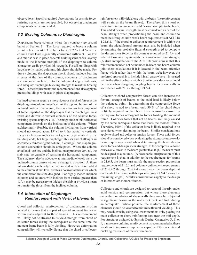
Seismic Design of Cast-in-Place Concrete Diaphragms, Chords, and Collectors: A Guide for Practicing Engineers
22
observations. Specific required observations for seismic force-resisting systems are not specified, but observing diaphragm components is recommended.
8.3 Bracing Columns to Diaphragms
Diaphragms brace columns where they connect (see second bullet of Section 2). The force required to brace a column is not defined in ACI 318, but a force of 2 % to 4 % of the column axial load is generally considered sufficient. For low and midrise cast-in-place concrete buildings this check is rarely made as the inherent strength of the diaphragm-to-column connection easily provides this strength. For tall buildings with large heavily loaded columns, this check should be made. For these columns, the diaphragm check should include bearing stresses at the face of the column, adequacy of diaphragm reinforcement anchored into the column at edge conditions, and adequate diaphragm buckling strength to resist the bracing force. These requirements and recommendations also apply to precast buildings with cast-in-place diaphragms.
Inclined columns require a more rigorous check of forces at the diaphragm-to-column interface. At the top and bottom of the inclined portion of a column, there is a horizontal component of force imparted on the diaphragm that the diaphragm must resist and deliver to vertical elements of the seismic force-resisting system (Figure 2-1). The magnitude of this horizontal component depends on the inclination of the column. Where architecturally feasible, the column inclination from vertical should not exceed about 15° (1 to 4, horizontal to vertical). Larger inclination angles are not generally proscribed by the building code, but large diaphragm thrusts and challenges in adequately reinforcing the column, diaphragm, and diaphragm-column connection should be anticipated. Where the column axial loads are low and the inclination approaches vertical, the slab may be capable of resisting the horizontal component. The slab may also be adequate at intermediate levels were the inclined column passes without a change in direction. At these intermediate levels only the incremental vertical force added to the column at that level creates a horizontal thrust for which the connection must be designed. For highly loaded inclined columns and columns with inclines from vertical greater than 15°, it may be necessary to thicken the slab or provide a beam to transfer the thrust from the inclined column.
8.4 Interaction of Diaphragm Reinforcement with Vertical Elements
Chord and collector reinforcement of diaphragms is often located in beams that are part of special moment frames or within slabs adjacent to those beams. This reinforcement will likely not be stressed to its yield strength from chord or collector forces during the earthquake at the same time the moment frame beam is fully yielding. However, deformation compatibility will typically dictate that the chord or collector
reinforcement will yield along with the beam (the reinforcement will strain as the beam flexes). Therefore, this chord or collector reinforcement will add flexural strength to the beam. This added flexural strength must be considered as part of the beam strength when proportioning the beam and column to meet the strong-column-weak-beam requirements of ACI 318 § 21.6.2. If the chord or collector reinforcement is within the beam, the added flexural strength must also be included when determining the probable flexural strength used to compute the design shear force for the beam as required by 21.5.4, and when determining requirements for beam-column joint strength. (A strict interpretation of the ACI 318 provisions is that this reinforcement need not be included in beam and beam-column joint shear calculations if it is located in the beam effective flange width rather than within the beam web; however, the preferred approach is to include it in all cases where it is located within the effective beam width.) Similar considerations should be made when designing coupling beams for shear walls in accordance with 21.5.2 through 21.5.4.
Collector or chord compressive forces can also increase the flexural strength of beams as the axial load is likely below the balanced point. In determining the compressive force of a chord to add to a beam, only 30 % of the chord force is likely required as the chord force is usually caused by earthquake forces orthogonal to forces loading the moment frame. Collector forces that act on beams are likely caused by the same earthquake force that loads the moment frame. Therefore, 100 % of the collector force is likely required to be considered when designing the beam. Similar considerations apply to chord and collector tension forces. These axial forces should be considered when evaluating the strong-column-weak-beam requirements and when determining the beam design shear force and design shear strength. If the compressive force causes axial stress in the beam greater than 0.1f ’c, the beam must be designed as a column. (A reasonable interpretation of this requirement is that, in addition to the requirements for beams in 21.6.5, the beam must satisfy the gross-section proportion requirements of 21.6.1 and column confinement requirements of 21.6.4.2 through 21.6.4.4 along twice the beam depth at each end of the beam, with hoops satisfying 21.6.4.5 along the remaining length.) Similar considerations apply to the design of intermediate moment frames.
Collectors and chords are designed to respond linearly under axial tension and compression, but where these elements enter the boundaries of shear walls they may be subjected to significant flexure as the walls rock back and forth during an earthquake. Where possible, the reinforcement of these elements should be located to minimize flexural yielding. This may be achieved by using shallower members or by placing the main collector or chord reinforcing bars near the mid-depth. For structures assigned to Seismic Design Categories D, E, or F, transverse confining reinforcement is recommended at these locations to improve compressive capacity of the concrete and buckling resistance of the reinforcement.

23Seismic Design of Cast-in-Place Concrete Diaphragms, Chords, and Collectors: A Guide for Practicing Engineers
9. Detailing & Constructability Issues 9.1 Diaphragm Reinforcement
Many concrete slabs are designed to have a continuous bottom mat of uniformly distributed reinforcement. For this reason, transverse reinforcement provided for diaphragm shear resistance is commonly incorporated into the bottom mat. In heavily reinforced diaphragms that are thick slabs, a continuous top and bottom mat of reinforcement is often provided. Designers should specify the required lap splice and development length of the reinforcement in the construction documents, as diaphragm reinforcement splice and development requirements may exceed what is otherwise required.
In post-tensioned slabs, the location of diaphragm reinforcement needs to be coordinated with the locations of post-tensioned strands and associated anchorages. Designating layers within the slab depth for the diaphragm reinforcement and the post-tensioned strands is an effective method of minimizing conflict. The design of the slab needs to take into account the actual location of the layers of reinforcement if this approach is used.
Welded wire fabric is not generally used for diaphragm reinforcement in cast-in-place slabs because the reinforcement provided for gravity support uses standard reinforcing bars. The use of welded wire fabric for diaphragm reinforcement is typically limited to topping slabs over precast concrete systems or over steel metal decks.
9.2 Collector and Chord Detailing
Collector and chord reinforcement is often located in the mid-depth of the slab. In structures assigned to Seismic Design Categories D, E, and F, ACI 318 requires center-to-center spacing at least 3db, but not less than 1.5 in., and concrete clear cover at least 2.5db, but not less than 2 in. Otherwise, transverse reinforcement is required.
Connections of collector reinforcement to vertical elements of the seismic force-resisting system are often congested regions. In many cases, numerous large diameter bars are required to be developed into confined boundary zones of shear walls as shown in Figure 9-1a. Designers should study these connections in detail to ensure adequate space exists. In many cases, increased slab thickness or beams are required to accommodate reinforcement detailing at the connections. Figure 9-1b shows where a beam was created to accommodate the collector reinforcement. Designers should also consider the slab depth provided where large collectors intersect. Multiple layers of large diameter reinforcing bars can result in excessive congestion. Similarly, designers should be aware of locations where collectors intersect concrete beam longitudinal reinforcement.
Figure 9-1 – Collector detailing.
Long collectors, such as the one shown in Figure 9-2, can accumulate strains over their length resulting in displacements that may be incompatible with modeling assumptions or deformation capacities of adjacent components. Designers can consider additional collector reinforcement to reduce the strain and associated collector elongation. Providing confinement reinforcement can also increase the ductility of the concrete locally, but will not address potential problems associated with incompatible deformations. Redesigning the force transfer system should also be considered.
Where collector (or chord) reinforcement is required at a location coincident with a beam, the chord reinforcement can be placed within the beam. Beam transverse reinforcement, if properly detailed, can also serve as collector (or chord) confinement. If chord reinforcement does not fit entirely within the beam width, then the effective diaphragm depth should be based on the actual distribution and location of the chord reinforcement.
(b) Beam for large collector
(a) Collector connection to shear wall boundary zone
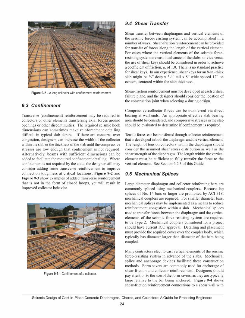
Seismic Design of Cast-in-Place Concrete Diaphragms, Chords, and Collectors: A Guide for Practicing Engineers
24
Figure 9-2 – A long collector with confinement reinforcement.
9.3 Confinement
Transverse (confinement) reinforcement may be required in collectors or other elements transferring axial forces around openings or other discontinuities. The required seismic hook dimensions can sometimes make reinforcement detailing difficult in typical slab depths. If there are concerns over congestion, designers can increase the width of the collector within the slab or the thickness of the slab until the compressive stresses are low enough that confinement is not required. Alternatively, beams with sufficient dimensions can be added to facilitate the required confinement detailing. Where confinement is not required by the code, the designer still may consider adding some transverse reinforcement to improve connection toughness at critical locations; Figure 9-2 andFigure 9-3 show examples of added transverse reinforcement that is not in the form of closed hoops, yet will result in improved collector behavior.
Figure 9-3 – Confinement of a collector.
9.4 Shear Transfer
Shear transfer between diaphragms and vertical elements of the seismic force-resisting system can be accomplished in a number of ways. Shear-friction reinforcement can be provided for transfer of forces along the length of the vertical element. For cases where the vertical elements of the seismic force-resisting system are cast in advance of the slabs, or vice versa, the use of shear keys should be considered in order to achieve a coefficient of friction, µ, of 1.0. There is no standard practice for shear keys. In our experience, shear keys for an 8-in.-thick slab might be ¾” deep x 3½” tall x 8” wide spaced 12” on centers, centered within the slab thickness.
Shear-friction reinforcement must be developed at each critical failure plane, and the designer should consider the location of the construction joint when selecting μ during design.
Compressive collector forces can be transferred via direct bearing at wall ends. An appropriate effective slab bearing area should be considered, and compressive stresses in the slab should be evaluated to determine if confinement is required.
Tensile forces can be transferred through collector reinforcement that is developed in both the diaphragm and the vertical element. The length of tension collectors within the diaphragm should consider the assumed shear stress distribution as well as the shear strength of the diaphragm. The length within the vertical element must be sufficient to fully transfer the force to the vertical element. See Section 6.2.3 of this Guide.
9.5 Mechanical Splices
Large diameter diaphragm and collector reinforcing bars are commonly spliced using mechanical couplers. Because lap splices of No. 14 bars or larger are prohibited by ACI 318, mechanical couplers are required. For smaller diameter bars, mechanical splices may be implemented as a means to reduce reinforcement congestion within a slab. Mechanical splices used to transfer forces between the diaphragm and the vertical elements of the seismic force-resisting system are required to be Type 2. Mechanical couplers considered for a project should have current ICC approval. Detailing and placement must provide the required cover over the coupler body, which typically has diameter larger than diameter of the bars being coupled.
Many contractors elect to cast vertical elements of the seismic force-resisting system in advance of the slabs. Mechanical splice and anchorage devices facilitate these construction methods. Form savers are commonly used for anchorage of shear-friction and collector reinforcement. Designers should pay attention to the size of the form savers, as they are typically large relative to the bar being anchored. Figure 9-4 shows shear-friction reinforcement connections to a shear wall with

25Seismic Design of Cast-in-Place Concrete Diaphragms, Chords, and Collectors: A Guide for Practicing Engineers
Figure 9-4 – Form savers for dowel anchorage.
form savers. As with mechanical couplers, any form saver considered for a project should have current ICC approval.
9.6 Conduits and Embedded Services
The placement of electrical conduit, plumbing sleeves, and other services within a reinforced concrete slab is common practice. Figure 9-5 shows an extreme example of embedded conduit within a reinforced concrete diaphragm.
Figure 9-5 – Embedded conduit.
Designers should consider these and similar items that can reduce the capacity and stiffness of the diaphragm. Typical details showing restrictions on the placement of conduits and embedded services and associated supplemental reinforcement are helpful, but often are insufficient to cover many of the conditions that occur in a project. The specifications or General Notes should identify specific mandatory restrictions; for example, for post-tensioned construction it could be mandatory that conduit or other embedded items not displace the vertical profile of the tendons. Contract Documents should require the contractor to provide detailed layout drawings of the conduits and other embedded services well in advance of
concrete placement. This allows the designer time to review the impact to the diaphragm and to provide supplemental instructions, including additional reinforcement, as required. Pre-construction meetings can provide an opportunity for the designer to review placement and reinforcement requirements in detail prior to construction.
The location of nonstructural items embedded in the slab should also be considered with respect to collector layout. In many instances, conflicts between structural and nonstructural items can be problematic. Figure 9-6 shows a conflict in the location of a nonstructural component with the alignment of the collector reinforcement.
Figure 9-6 – Conflict between the location of collector reinforcing with a nonstructural component.
9.7 Location of Construction Joints
Construction joints create weakened planes within a diaphragm. They can also impact development and splices of reinforcement. Shear-friction reinforcement can be provided across construction joints if necessary to maintain continuity of the diaphragm in shear. The impacts to the continuity and development of chord and collector reinforcement at construction joints should also be understood. As with conduits, typical details, limitations, and instructions should be clearly detailed in the Contract Documents. Contract Documents should also require that contractors provide detailed construction joint layout drawings well in advance of concrete placement.
Seismic Design of Cast-in-Place Concrete Diaphragms, Chords, and Collectors: A Guide for Practicing Engineers
26
10. ReferencesACI (2008). Building code requirements for structural concrete (ACI 318-08) and commentary, American Concrete Institute, Farmington Hills, MI.
ASCE (2010). Minimum design loads for buildings and other structures (ASCE/SEI 7-10), American Society of Civil Engineers, Reston, VA.
Chopra, A.K. (2005). Earthquake dynamics of structures: A primer, 2nd Edition, Earthquake Engineering Research Institute, Oakland, California, 129 pp.
Corley, W.G., Cluff, L., Hilmy, S., Holmes, W., Wight, J. (1996). “Concrete parking structures,” Northridge Report Vol. 2, Earthquake Spectra, V. 11, Supplement C, pp. 75-98.
Deierlein, G., Reinhorn, A.M., and Willford, M. (2010). “Nonlinear structural analysis for seismic design,” NEHRP Seismic Design Technical Brief No. 4 (NIST GCR 10-917-5).
Fleischman, R.B., Farrow, K.T., Eastman, K. (2002). “Seismic performance of perimeter lateral system structures with highly flexible diaphragms,” Earthquake Spectra, 18 (2), May 2002.
IBC (2009). International Building Code, International Code Council, Washington, DC.
Nakaki, S.D. (2000). “Design guidelines for precast and cast-in-place concrete diaphragms,” EERI professional fellowship report, Earthquake Engineering Research Institute, Oakland, CA.
Rodriguez, M.E., Restrepo, J.I., and Blandón, J.J. (2007). “Seismic design forces for rigid floor diaphragms in precast concrete building structures,” Journal of Structural Engineering, ASCE, 133 (11) November 2007, pp. 1604-1615.
Sabelli R., Pottebaum, W., Dean, B. (2009). “Diaphragms for seismic loading,” Structural Engineer, Part 1, January, pp. 24-29, Part 2, February 2009, pp. 22-23.
SEAOC (2005). “Using a concrete slab as a collector,” Seismology and Structural Standards Committee, Structural Engineers Association of California, 15 pp.
SEAOC (2009). “Concrete parking structures,” The SEAOC Blue Book: seismic design recommendations, Structural Engineers Association of California, Sacramento, CA, www.seaoc.org/blubook, 9 pp. For an abridged version, see SEAOC (2010). “Seismic design of concrete parking structure ramps,” Seismology Committee, Structural Engineers Association of California, STRUCTURE magazine, July 2010. http://www.structuremag.org/article.aspx?articleID=1096.
Shakal, A.F. et al. (1995). “Recorded ground and structure motions,” Earthquake Spectra 11 (S2), April 1995, pp. 13-96.

27Seismic Design of Cast-in-Place Concrete Diaphragms, Chords, and Collectors: A Guide for Practicing Engineers
11. Notations and Abbreviations
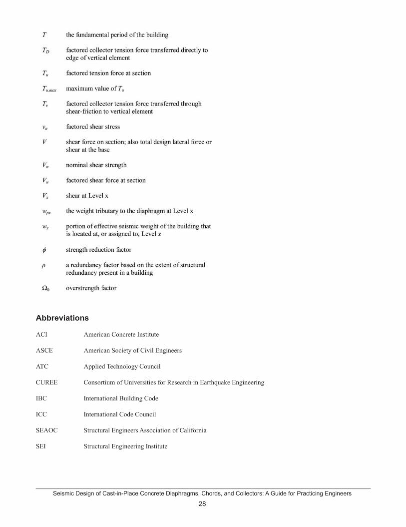
Seismic Design of Cast-in-Place Concrete Diaphragms, Chords, and Collectors: A Guide for Practicing Engineers
28
Abbreviations
ACI American Concrete Institute
ASCE American Society of Civil Engineers
ATC Applied Technology Council
CUREE Consortium of Universities for Research in Earthquake Engineering
IBC International Building Code
ICC International Code Council
SEAOC Structural Engineers Association of California
SEI Structural Engineering Institute

29Seismic Design of Cast-in-Place Concrete Diaphragms, Chords, and Collectors: A Guide for Practicing Engineers
12. CreditsCover photo Image courtesy of Farzad Naeim, John A. Martin & Associates, Inc.
Figure 1-1 Image courtesy of Jack Moehle
Figure 2-1 Image courtesy of Jack Moehle
Figure 3-1 Image courtesy of Jack Moehle
Figure 3-2 Image courtesy of Jack Moehle
Figure 3-3 Image courtesy of Jack Moehle
Figure 4-1 Image courtesy of Jack Moehle
Figure 4-2 Image courtesy of Jack Moehle
Figure 4-3 Image courtesy of Jack Moehle
Figure 4-4 Image courtesy of Jack Moehle
Figure 5-1 Image courtesy of Jack Moehle
Figure 6-1 Image courtesy of Jack Moehle
Figure 6-2 Image courtesy of Jack Moehle
Figure 6-3 Image courtesy of Dominic Kelly
Figure 6-4 Image courtesy of Stephen Harris, Simpson Gumpertz & Heger, Inc.
Figure 6-5 Image courtesy of Jack Moehle
Figure 6-6 Image courtesy of Dominic Kelly
Figure 6-7 Image courtesy of Jack Moehle and Dominic Kelly
Figure 6-8 Image courtesy of Jack Moehle and Dominic Kelly
Figure 6-9 Image courtesy of Jack Moehle and Dominic Kelly
Figure 6-10 Image courtesy of Dominic Kelly
Figure 6-11 Image courtesy of Jack Moehle
Figure 7-1 Image courtesy of Jack Moehle
Figure 7-2 Image courtesy of Jack Moehle
Figure 7-3 Image courtesy of Jack Moehle
Figure 7-4 Image courtesy of Jack Moehle
Figure 7-5 Image courtesy of Jack Moehle
Figure 9-1 Image courtesy of Magnusson Klemencic Associates
Figure 9-2 Image courtesy of Stephen Harris, Simpson Gumpertz & Heger, Inc.
Figure 9-3 Image courtesy of Stephen Harris, Simpson Gumpertz & Heger, Inc.
Figure 9-4 Image courtesy of Magnusson Klemencic Associates
Figure 9-5 Image courtesy of Magnusson Klemencic Associates
Figure 9-6 Image courtesy of Magnusson Klemencic Associates