Embed Size (px)
Citation preview
SEISMIC CODE EVALUATION
GUATEMALA Evaluation conducted by Guillermo Santana
NAME OF DOCUMENT: “Normas Estructurales de Diseño y Construcción Recomendadas para la República de Guatemala” (Recommended Structural Standard for Design and Construction for the Republic of Guatemala) YEAR: 1996 GENERAL REMARKS: Document elaborated by a technical committee, chartered in 1986, under the supervision of the Ministry of Communications, Transportation and Public Works of the Government of the Republic of Guatemala. SPECIFIC ITEMS: NOTE: Bracketed numbers refer to Code specific chapters or articles: [1.2.3] Parentheses numbers refer to Items of this document: (see 2.2) 1. SCOPE
1.1 Explicit Concepts. [Sect. 1-1.1] The norm applies to the design and construction of new buildings, as well as to the repair and retrofitting of existing facilities. It includes load prescriptions only for earthquake, although the outline states wind and even volcanic ash deposition loading, with the associated zoning. It is clear to the reviewer that the technical committee was commissioned to write a norm for all types of loading conditions but somehow their effort fell short. 1.2 Performance Objectives. [Sect. 1-1.1] The performance objectives are stated as a) to safeguard against loss of life and to reduce the possibility of physical damages to persons; b) to provide a minimum of structural quality so that integrity of the facility being subjected to both permanent and frequent loading can be preserved and c) to provide protection against direct or indirect damage caused by adverse natural agents. Permanent and frequent loading are to include dead load, live load, and lateral pressures. Adverse natural agents considered are earthquakes, slope instability, volcanic activity and meteorological and environmental actions.
2. SEISMIC ZONING AND SITE CHARACTERIZATION
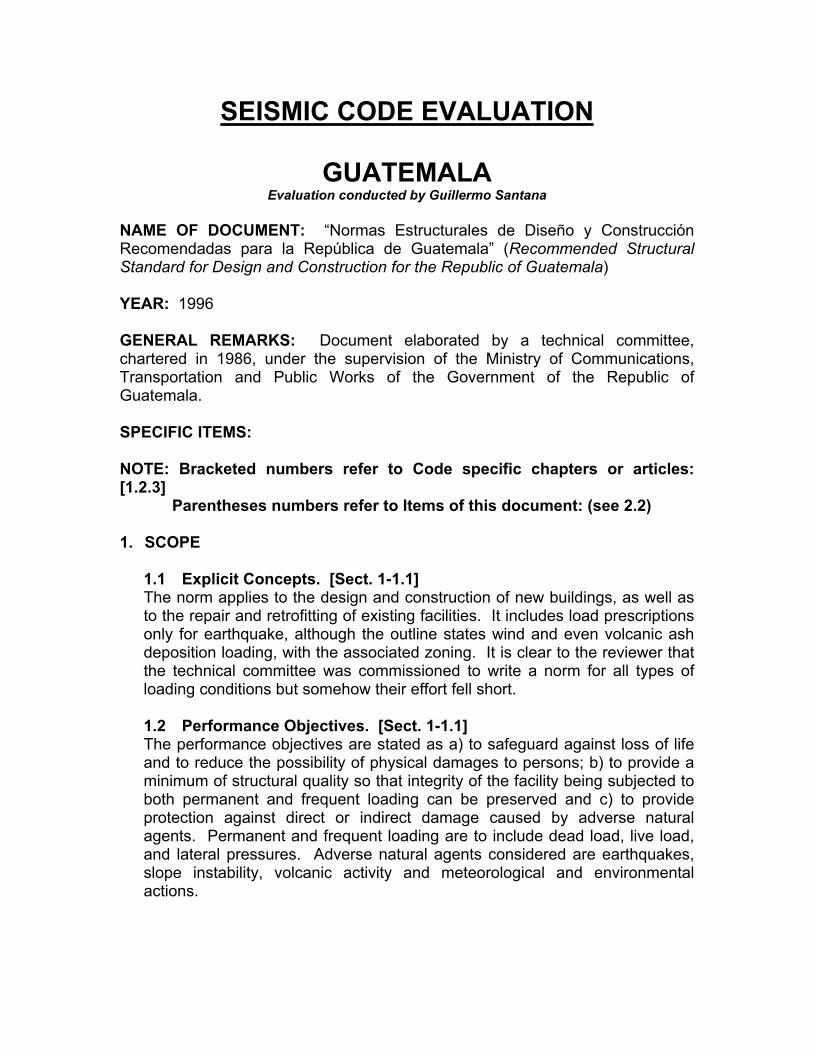
2.1 Seismic Zoning (Quality of Data). [Sect. 2-2.1] The country is divided into four seismic zones. The lowest level is assigned to the northeastern half of the country. This area, shown in the map below, covers 30 percent of the country as well as Belize (for which a territorial dispute is still unresolved since colonial days). The other two thirds of the country is divided into the additional three zones, which increase in intensity as it gets to the Pacific Ocean. The map reflects the two major seismogenic zones in Guatemala, the Motagua Polochic Fault and the Subduction zone.
2.2 Levels of Seismic Intensity. [Sect. 2-2.2.3] Three seismic intensity levels are considered in this standard: frequent, severe and extreme. The level corresponding to the severe earthquake corresponds to the base level. The frequent earthquake is assigned a lower acceleration level in every seismic zone. The extreme earthquake is finally defined as the event that will produce a 30% increase in the effective peak acceleration levels with respect to the severe case.
2
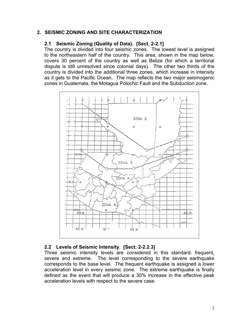
Seismic Zone Io Ao Af Ae 2 2 0.10g 0.00g 0.13g 3 3 0.10 a 0.30g 0.00 a 0.10g 0.13 a 0.39g
4.1 4 0.30g 0.10 a 0.15g 0.39g 4.2 4 0.30g 0.15g 0.39g
2.3 Near Fault considerations. No near-fault considerations are provided in this document. 2.4 Site Requirements. [Sect. 2-2.2.3] Three soil types are established. Soft (S3), medium (S2) and hard soil and rock (S1) definitions are given in terms of depth of strata, geophysical properties and composition. In locations where the soil properties are not known in sufficient detail to determine the soil profile type, the more critical case of either medium or soft soil profile is to be used. Chapter 2-5 is dedicated entirely to soil and terrain conditions to be considered. First a basic criteria is defined and the microzonation criteria is given by defining different precautionary zones according to the principal features of the topography of Guatemala City and other major urban centers. Emphasis is given to identifying slope instability, ground failure due to faulting and liquefaction. Special provisions are given for sites to be used for facilities assigned a seismicity index of 5, the highest level. 2.5 Site Classification. [Sect. 2-2.2.3] The site definitions and associated coefficients are given in the following table
TABLE 1. SITE COEFFICIENTS
Type Description S1 A soil profile with either:
(a) Rock of any characteristic. Such material may be characterized by a shear wave velocity greater than 800 m/s, or (b) stiff soil conditions where the soil depth is less than 50 m and the soil type overlying rock are stable deposits of volcanic ashes, sands, gravels, or stiff clays.
S2 A soil profile with deep cohesionless or stiff clay conditions, including sites where the soil depth exceeds 50 m and the soil types overlying rock are stable deposits of volcanic ashes, sands, gravels, or stiff clays. In locations where the soil properties are not known in sufficient detail to determine the soil profile type or where the profile does not fit any of the three types, this profile type should be used.
S3 A soil profile with soft- to medium-stiff clays, volcanic ashes and sands, characterized by 10 m or more of soft- to medium-stiff clays with or without intervening layers of sand or other cohesionless soils. In general, soil profiles characterized by a shear wave velocity of less than 200 m/s.
2.6 Peak Ground Accelerations (Horizontal and Vertical). [Sect. 2-2.2] Horizontal effective peak ground accelerations are defined in terms of the Ao coefficient presented in (2.2) above. Peak accelerations range from 0.00g in Zone 2 to 0.39g in Zone 4.2 for earthquakes defined as frequent, base design and extreme levels. As a not so properly edited translation of ATC 3-06, this norm requires that for buildings assigned categories C and D (Seismic Performance Categories), the vertical component of earthquake motion be
3
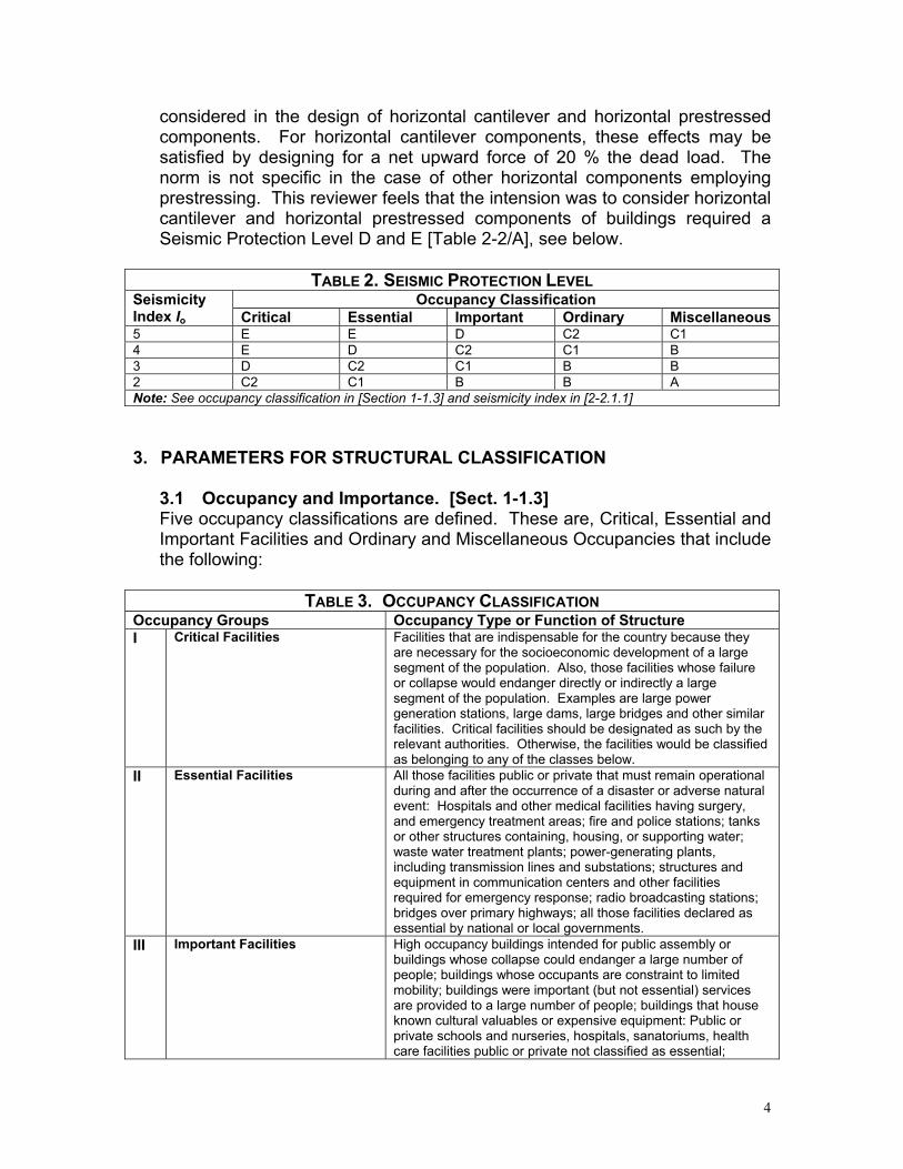
considered in the design of horizontal cantilever and horizontal prestressed components. For horizontal cantilever components, these effects may be satisfied by designing for a net upward force of 20 % the dead load. The norm is not specific in the case of other horizontal components employing prestressing. This reviewer feels that the intension was to consider horizontal cantilever and horizontal prestressed components of buildings required a Seismic Protection Level D and E [Table 2-2/A], see below.
TABLE 2. SEISMIC PROTECTION LEVEL Occupancy Classification Seismicity
Index Io Critical Essential Important Ordinary Miscellaneous5 E E D C2 C1 4 E D C2 C1 B 3 D C2 C1 B B 2 C2 C1 B B A Note: See occupancy classification in [Section 1-1.3] and seismicity index in [2-2.1.1]
3. PARAMETERS FOR STRUCTURAL CLASSIFICATION
3.1 Occupancy and Importance. [Sect. 1-1.3] Five occupancy classifications are defined. These are, Critical, Essential and Important Facilities and Ordinary and Miscellaneous Occupancies that include the following:
TABLE 3. OCCUPANCY CLASSIFICATION
Occupancy Groups Occupancy Type or Function of Structure I Critical Facilities Facilities that are indispensable for the country because they
are necessary for the socioeconomic development of a large segment of the population. Also, those facilities whose failure or collapse would endanger directly or indirectly a large segment of the population. Examples are large power generation stations, large dams, large bridges and other similar facilities. Critical facilities should be designated as such by the relevant authorities. Otherwise, the facilities would be classified as belonging to any of the classes below.
II Essential Facilities All those facilities public or private that must remain operational during and after the occurrence of a disaster or adverse natural event: Hospitals and other medical facilities having surgery, and emergency treatment areas; fire and police stations; tanks or other structures containing, housing, or supporting water; waste water treatment plants; power-generating plants, including transmission lines and substations; structures and equipment in communication centers and other facilities required for emergency response; radio broadcasting stations; bridges over primary highways; all those facilities declared as essential by national or local governments.
III Important Facilities High occupancy buildings intended for public assembly or buildings whose collapse could endanger a large number of people; buildings whose occupants are constraint to limited mobility; buildings were important (but not essential) services are provided to a large number of people; buildings that house known cultural valuables or expensive equipment: Public or private schools and nurseries, hospitals, sanatoriums, health care facilities public or private not classified as essential;
4
vehicle parking facilities and garages not included as essential; jails; museums and other similar facilities; all buildings of more than 5 stories high or 3,000 m²; theaters; movie places; auditoriums; marketplaces; restaurants and similar facilities with occupancies of more than 300; warehouses or factories of toxic, explosive or flammable materials; water distribution networks; waste water networks.
IV Ordinary Occupancy All other structures not classified in any of the previous groups including housing, commercial or industrial facilities, warehouses whose importance or characteristics do not place them in any of the categories above.
V Miscellaneous Occupancy Industrial or agricultural facilities of low occupancy.
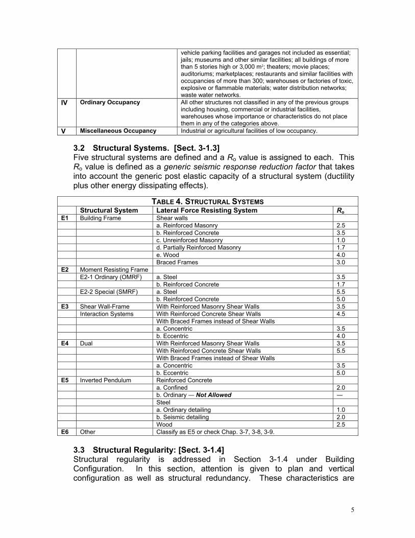
3.2 Structural Systems. [Sect. 3-1.3] Five structural systems are defined and a Ro value is assigned to each. This Ro value is defined as a generic seismic response reduction factor that takes into account the generic post elastic capacity of a structural system (ductility plus other energy dissipating effects).
TABLE 4. STRUCTURAL SYSTEMS
Structural System Lateral Force Resisting System Ro E1 Building Frame Shear walls a. Reinforced Masonry 2.5 b. Reinforced Concrete 3.5 c. Unreinforced Masonry 1.0 d. Partially Reinforced Masonry 1.7 e. Wood 4.0 Braced Frames 3.0 E2 Moment Resisting Frame E2-1 Ordinary (OMRF) a. Steel 3.5 b. Reinforced Concrete 1.7 E2-2 Special (SMRF) a. Steel 5.5 b. Reinforced Concrete 5.0 E3 Shear Wall-Frame With Reinforced Masonry Shear Walls 3.5 Interaction Systems With Reinforced Concrete Shear Walls 4.5 With Braced Frames instead of Shear Walls a. Concentric 3.5 b. Eccentric 4.0 E4 Dual With Reinforced Masonry Shear Walls 3.5 With Reinforced Concrete Shear Walls 5.5 With Braced Frames instead of Shear Walls a. Concentric 3.5 b. Eccentric 5.0 E5 Inverted Pendulum Reinforced Concrete a. Confined 2.0 b. Ordinary ― Not Allowed ― Steel a. Ordinary detailing 1.0 b. Seismic detailing 2.0 Wood 2.5 E6 Other Classify as E5 or check Chap. 3-7, 3-8, 3-9.
3.3 Structural Regularity: [Sect. 3-1.4] Structural regularity is addressed in Section 3-1.4 under Building Configuration. In this section, attention is given to plan and vertical configuration as well as structural redundancy. These characteristics are
5
quantified by means of a Seismic Resistance Quality Factor Q, formally defined in Section 3-1.2 as Q 1.00 0.01 i= + q∑ . If Q < 0.80 for any direction of analysis, then the project must be modified. The philosophy behind this approach is to qualify the structural conception of the building so as to allow the designer more freedom of choice. The reviewer has no knowledge of any similar approach in any other codes written in the Americas. Purportedly, this kind of approach would result in a better understanding of building behavior by designer as well as by owners and users of the facility. The quality factor approach does not apply to structural system E5, neither to shells, membranes, nor buildings without diaphragms. Plan Regularity is awarded if more than 75% of the building area above the base level is composed of regular floors without reentrant corners or overhangs; no excessive eccentricity between center of mass and center of rigidity; i.e., the ratio ex/Lx or ey/Ly is less than 0.15 and no excessive stiffness anisotropy; i.e., translational stiffness per floor in each direction lies between 0.67 and 1.5, and 0.33 < Lx/Ly < 3.0. Vertical Regularity is awarded if no setbacks are present; the mass/stiffness ratio does not change by more than 15% between adjacent levels and if internal partitions do not participate in the lateral force resistance system.
3.4 Structural Redundancy. [Sect. 3-1.4] As explained above in (3.3), structural redundancy is considered as part of the Q Factor. Redundancy is evaluated separately for each direction of analysis taken into consideration number of clear spans, number of structural axes (i.e. structural components) and number of shear walls for that direction. The highest Q factor is assigned to a building with four or more equal spans and five or more structural components with shear walls (or eccentrically braced frames) in at least one third of them. No explicit requirements are given here concerning diaphragm stiffness.
3.5 Ductility of elements and components. [Sect. 3-1.2] Ductility is not address explicitly in the portion of the standard being evaluated. Rather, a Seismic Response Reduction Factor R is defined for each structural system that is expressed as 1.2 oR R Q= , where both Ro and Q have been previously defined, see (3.2) and (3.3). The R factor is based on an adaptation of the published technical literature of the early 90’s. The commentaries state that the R factor as stated is perhaps overly simplified, but no attempt is made to present any corrections. Element ductility is considered in [Sect. 7-1.4] where requirements for Special Moment Frames are given as an extension of ACI 318-89 and other sources. Chapter 7-1, Reinforced Concrete is not being evaluated for the present work.
6
4. SEISMIC ACTIONS
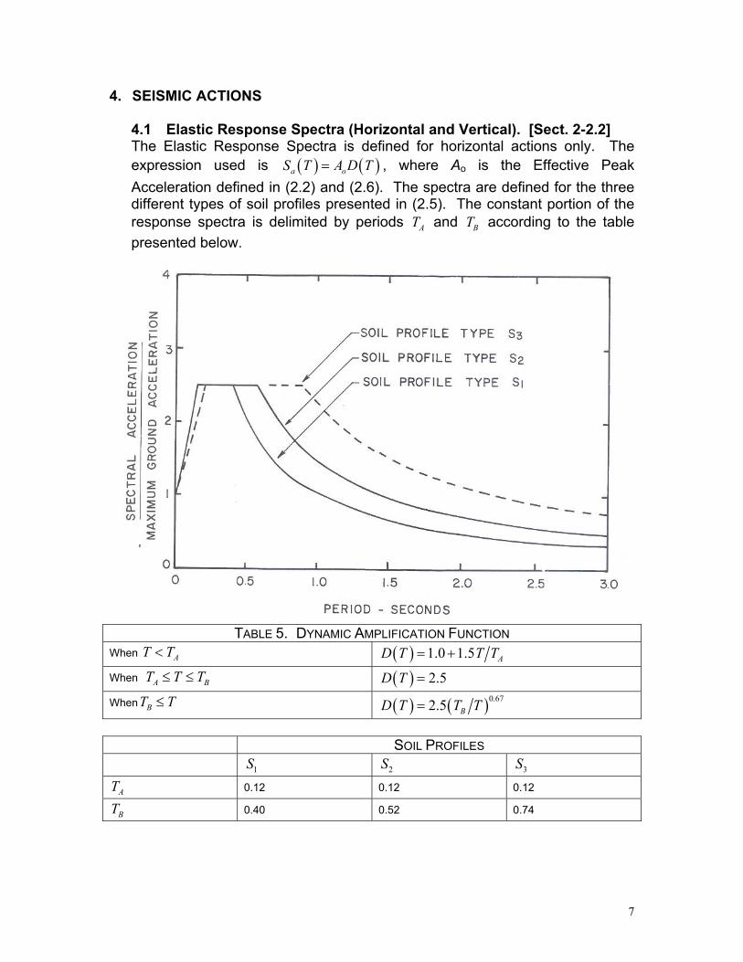
4.1 Elastic Response Spectra (Horizontal and Vertical). [Sect. 2-2.2] The Elastic Response Spectra is defined for horizontal actions only. The expression used is ( ) ( )a oS T A D T= , where Ao is the Effective Peak Acceleration defined in (2.2) and (2.6). The spectra are defined for the three different types of soil profiles presented in (2.5). The constant portion of the response spectra is delimited by periods T and T according to the table presented below.
A B
TABLE 5. DYNAMIC AMPLIFICATION FUNCTION
When AT T< ( ) 1.0 1.5 AD T T T= +
When T T A BT≤ ≤ ( ) 2.5D T =
WhenT T B ≤ ( ) ( )0.672.5 BD T T T=
SOIL PROFILES
1S 2S 3S
AT 0.12 0.12 0.12
BT 0.40 0.52 0.74
7
4.2 Design Spectra. The Design Spectra are defined in terms of the Elastic Response Spectra and the Seismic Response Reduction Factor R defined above. See (3.5). The combination of these two elements defines the Design Seismic Forces. 4.3 Representation of acceleration time histories. Acceleration time histories are not explicitly considered in this document. 4.4 Design Ground Displacement. The design ground displacement is not explicitly considered.
5. DESIGN FORCES, METHODS OF ANALYSIS AND DRIFT LIMITATIONS
5.1 Load Combinations including Orthogonal Seismic Load Effects. Load Combinations are given in [Sect. 2-7.5] as:
a) For all construction systems including R/C, steel, wood, masonry:
1.20.8
U M VU M S
S= + ±= ±
b) For design of walls and columns, the last equation in a) can be
limited to U M S= ±
where M = Dead load V = Live load S = Horizontal seismic action Orthogonal Seismic Load Effects are considered in [Sect. 3-1.8.2] where it is stated that vertical elements and its foundations must be designed for 100% of the effect in one direction plus 30% of the vertical load due to seismic action in the orthogonal direction.
5.2 Simplified Analysis and Design Procedures. A simplified analysis procedure for small dwellings and minor construction is promised in the general outline but not delivered. The outline simply states that it is still pending. 5.3 Static Method Procedures. An Equivalent Seismic Force Method is prescribed in [Chapter 3-2]. The method applies to buildings classified as regular in plan and elevation according to [Sect. 3-1.4]. See (3.3). Additionally, this method applies only to buildings that do not exceed 50 meters in height and whose fundamental period of vibration does not exceed 1.5 seconds. The total base shear is
8
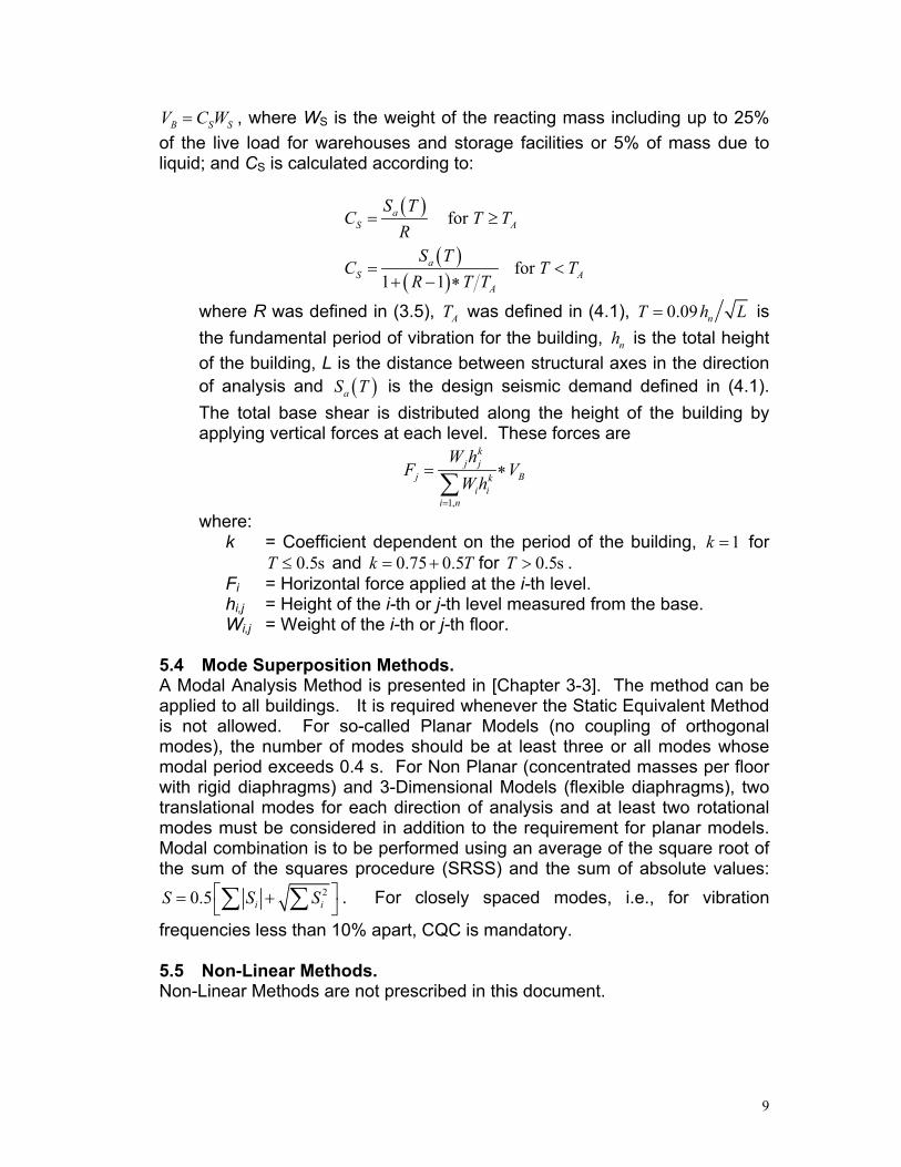
B SV C W= S , where WS is the weight of the reacting mass including up to 25% of the live load for warehouses and storage facilities or 5% of mass due to liquid; and CS is calculated according to:
( )
( )( )
for
for 1 1
aS A
aS A
A
S TC T T
RS T
C TR T T
= ≥
T= <+ − ∗
where R was defined in (3.5), was defined in (4.1), AT 0.09 nh=T is the fundamental period of vibration for the building, is the total height of the building, L is the distance between structural axes in the direction of analysis and is the design seismic demand defined in (4.1). The total base shear is distributed along the height of the building by applying vertical forces at each level. These forces are
L
nh
( )aS T
1,
kj j
j Bki i
i n
W hF V
Wh=
= ∗∑
where: k = Coefficient dependent on the period of the building, for
and 1k =
0.5sT ≤ 0.75 0.5k T= + for T . 0.5s>Fi = Horizontal force applied at the i-th level. hi,j = Height of the i-th or j-th level measured from the base. Wi,j = Weight of the i-th or j-th floor.
5.4 Mode Superposition Methods. A Modal Analysis Method is presented in [Chapter 3-3]. The method can be applied to all buildings. It is required whenever the Static Equivalent Method is not allowed. For so-called Planar Models (no coupling of orthogonal modes), the number of modes should be at least three or all modes whose modal period exceeds 0.4 s. For Non Planar (concentrated masses per floor with rigid diaphragms) and 3-Dimensional Models (flexible diaphragms), two translational modes for each direction of analysis and at least two rotational modes must be considered in addition to the requirement for planar models. Modal combination is to be performed using an average of the square root of the sum of the squares procedure (SRSS) and the sum of absolute values:
20.5 iS S= +∑ ∑ iS . For closely spaced modes, i.e., for vibration
frequencies less than 10% apart, CQC is mandatory. 5.5 Non-Linear Methods. Non-Linear Methods are not prescribed in this document.
9
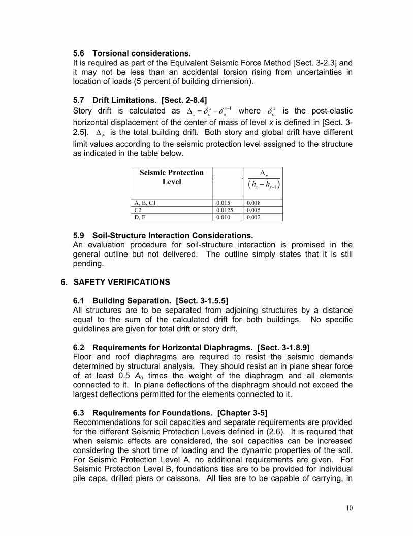
5.6 Torsional considerations. It is required as part of the Equivalent Seismic Force Method [Sect. 3-2.3] and it may not be less than an accidental torsion rising from uncertainties in location of loads (5 percent of building dimension).
5.7 Drift Limitations. [Sect. 2-8.4] Story drift is calculated as 1x x
x o oδ δ −∆ = − where xoδ is the post-elastic
horizontal displacement of the center of mass of level x is defined in [Sect. 3-2.5]. is the total building drift. Both story and global drift have different limit values according to the seismic protection level assigned to the structure as indicated in the table below.
N∆
Seismic Protection
Level 8 ∆
( )1
x
x xh h −
∆−
A, B, C1 0.015 0.018 C2 0.0125 0.015 D, E 0.010 0.012
5.9 Soil-Structure Interaction Considerations. An evaluation procedure for soil-structure interaction is promised in the general outline but not delivered. The outline simply states that it is still pending.
6. SAFETY VERIFICATIONS
6.1 Building Separation. [Sect. 3-1.5.5] All structures are to be separated from adjoining structures by a distance equal to the sum of the calculated drift for both buildings. No specific guidelines are given for total drift or story drift. 6.2 Requirements for Horizontal Diaphragms. [Sect. 3-1.8.9] Floor and roof diaphragms are required to resist the seismic demands determined by structural analysis. They should resist an in plane shear force of at least 0.5 Ao times the weight of the diaphragm and all elements connected to it. In plane deflections of the diaphragm should not exceed the largest deflections permitted for the elements connected to it. 6.3 Requirements for Foundations. [Chapter 3-5] Recommendations for soil capacities and separate requirements are provided for the different Seismic Protection Levels defined in (2.6). It is required that when seismic effects are considered, the soil capacities can be increased considering the short time of loading and the dynamic properties of the soil. For Seismic Protection Level A, no additional requirements are given. For Seismic Protection Level B, foundations ties are to be provided for individual pile caps, drilled piers or caissons. All ties are to be capable of carrying, in
10
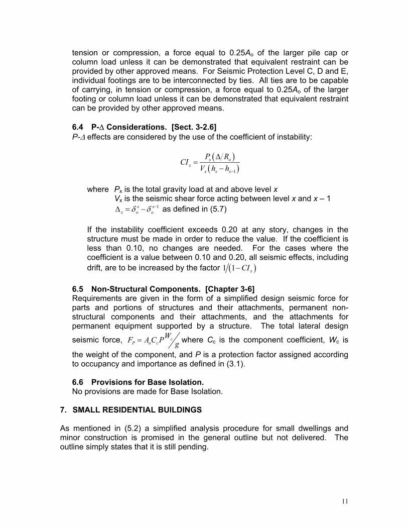
tension or compression, a force equal to 0.25Ao of the larger pile cap or column load unless it can be demonstrated that equivalent restraint can be provided by other approved means. For Seismic Protection Level C, D and E, individual footings are to be interconnected by ties. All ties are to be capable of carrying, in tension or compression, a force equal to 0.25Ao of the larger footing or column load unless it can be demonstrated that equivalent restraint can be provided by other approved means. 6.4 P-∆ Considerations. [Sect. 3-2.6] P-∆ effects are considered by the use of the coefficient of instability:
( )( )1
x ox
x x x
P RCI
V h h −
∆=
−
where Px is the total gravity load at and above level x Vx is the seismic shear force acting between level x and x – 1 1x x
x o oδ δ −∆ = − as defined in (5.7) If the instability coefficient exceeds 0.20 at any story, changes in the structure must be made in order to reduce the value. If the coefficient is less than 0.10, no changes are needed. For the cases where the coefficient is a value between 0.10 and 0.20, all seismic effects, including drift, are to be increased by the factor ( )1 1 xCI−
6.5 Non-Structural Components. [Chapter 3-6] Requirements are given in the form of a simplified design seismic force for parts and portions of structures and their attachments, permanent non-structural components and their attachments, and the attachments for permanent equipment supported by a structure. The total lateral design
seismic force, cP o c
WF A C P g= where Cc is the component coefficient, Wc is
the weight of the component, and P is a protection factor assigned according to occupancy and importance as defined in (3.1).
6.6 Provisions for Base Isolation. No provisions are made for Base Isolation.
7. SMALL RESIDENTIAL BUILDINGS As mentioned in (5.2) a simplified analysis procedure for small dwellings and minor construction is promised in the general outline but not delivered. The outline simply states that it is still pending.
11
8. PROVISIONS FOR EXISTING BUILDINGS Provisions are given for existing buildings only in as much as it requires that any retrofitting made should comply with the same level of forces prescribed for new buildings which is obviously too high for most existing facilities. As was the case with other sections in this evaluation, provisions for existing buildings and facilities is promised in the general outline but not delivered. The outline simply states that it is still pending.
RECOMMENDATIONS FOR CODE IMPROVEMENT A grand effort was made in 1987 and 1988 by a very good group ofpracticing structural engineers to produce a broad documentencompassing all aspects of seismic design of buildings and otherstructures. However, the effort fell quite short. The present edition ofthis Standard was redrafted in 1996 but, unfortunately, it has aconsiderable number of holes. It gives a very good roadmap of whatthe committee felt were the necessary topics to be covered by amodern code, but lot of sections are simply missing and no scheduleis offered for their inclusion in a future version of the document. Furthermore, this norm relied heavily in the ATC 3-06, even though itwas adopted by the Guatemalan Structural Engineering community in1996 when the reference document was already dated. The presentevaluation has revealed that the current Guatemalan provisions needto be updated quickly. Also, one major conclusion that can be drawn by the reviewer is thatno longer is it sufficient to update a seismic code for a particularcountry or region. It is also necessary to establish the institutionalsupport by which the periodical updating of the standard can beaccomplished. Perhaps the creation or strengthening of existingregional professional organizations focused on code developmentactivities is in order.
12