Embed Size (px)
Citation preview
1
First European Conference on Earthquake Engineering and Seismology (a joint event of the 13th ECEE & 30th General Assembly of the ESC)
Geneva, Switzerland, 3-8 September 2006 Paper Number: Keynote Address K8
SEISMIC BEHAVIOUR OF MASONRY DOMES AND VAULTS HAGIA SOPHIA IN ISTANBUL AND ST. FRANCIS IN ASSISI
Giorgio CROCI 1
SUMMARY
The paper is divided in three parts. In the first part the history of the domes and their realisation are shortly presented: the Pantheon, Hagia Sophia, St. Mary of the Flower in Florence, St. Peter in Rome. In the second part the behaviour of Hagia Sophia is analysed through its history, the observation of the present damage and mathematical models. The study shows how the dome collapsed several times in its history. The third part shows the collapse of two vaults of the Basilica of St. Francis of Assisi hit by a strong earthquake on 26 September, 1997. The mathematical model and photographic records explain the mechanism of collapse. Finally the reinforcements have been achieved using composite materials with aramidic fibers to strengthen the deformed existing vaults.
1. A SHORT HISTORY OF DOMES 1.1 Arches, domes and vaults The arch has probably been the most important innovation in the history of architecture, transforming, due to the curvature associated with the thrust at the springs, bending moments in compression forces, even if a certain bending strength is indispensable to maintain a stable shape. From arches to vaults and domes the step is small and the advantages of the compression-curvature behaviour are magnified. This is especially the case with domes, where the double curvature makes practically neglegible the bending effects, thus improving the global strength. Masonry, weak in tension, has been an ideal material to fit with these structural schemes. The seismic behaviour of vaults is very different in relation to their shape. Gothic vaults are usually weak not only due to their small thickness and imperfect connection between ribs and webs, but especially for the slenderness and deformability of the columns which is only partly compensated by the abutments. Probably Gothic Cathedrals haven’t been developed in Italy as they have been in Northern Europe. This is not only due to the different social conditions and culture (tink to the classicism of Rome and Greece) but also due to the seismicity of the country that makes those cathedrals very vulnerable to earthquakes. We’ll see in the last chapter the case of the Basilica of St. Francis of Assisi. Domes as already said, are intrinsically much stronger against earthquakes. Their possible weakness is mainly related to the stiffness and strength of the supporting structures. In the case of Hagia Sophia, as we’ll see in chapter 2, the deformability of the main pillars and supporting arches has been the cause of damage and collapse.
1 Professor Structural Restoration of Monuments and Historic Buildings, University of Rome “La Sapienza”.
Past President of ICOMOS International committee for Analysis and Restoration of Structures of Architectural Heritage.
2
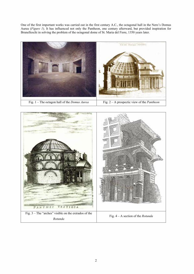
One of the first important works was carried out in the first century A.C., the octagonal hall in the Nero’s Domus Aurea (Figure 1). It has influenced not only the Pantheon, one century afterward, but provided inspiration for Brunelleschi in solving the problem of the octagonal dome of St. Maria del Fiore, 1350 years later.
Fig. 1 – The octagon hall of the Domus Aurea Fig. 2 – A prospectic view of the Pantheon
Fig. 3 – The “arches” visible on the extrados of the
Rotunda Fig. 4 – A section of the Rotunda

3
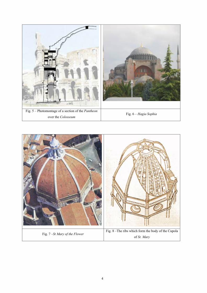
1.2 The Pantheon The Pantheon (built under the Emperor Adriano in the 2nd century a.C. – Figure 2) is apparently a very simple structure made of a cylinder (the Rotonda) and a hemispheric dome of the same diameter (around 43 m). However, if we look in detail, it is much more complex, full of intuitions and innovations. The relationship between the cylinder and the dome appears very different from outside and from inside. The dome from inside is clearly a hemisphere where the meridians spring vertically from the cylinder itself. From outside the cylinder appears higher than from inside and the dome emerges from the cornice with a flatter shape. Concerning the cylinder, from outside it appears as a big brick wall, containing within its thickness a series of arches (visible on the external face – Figure 3) which inside correspond to niches and empty spaces (Figure 4). These arches, which in reality are “false arches” built inside the masonry, are of particular interest as they show how the Romans preferred to utilise their large experience on arched structures (aqueducts, amphitheatres, etc.) rather than realise a huge continuous wall where it would have been more difficult to control the flow of forces, the influence of soil settlements during the construction, shrinkage and viscous phenomena. Probably the builders of the Pantheon were influenced by the Colosseum which, even if it appears completly different in its structure, in reality it is much similar to the Rotonda than would be expected. The photomontage of (Figure 5) gives an idea of that. The structural behaviour of the Pantheon has been analysed with mathematical models; in particular the seismic analysis has shown that the stresses are low, incapable of producing damage to a structure that globally is very strong due to the double curvature of the dome and the cylindrical shape of the base. In this way, the forces are directly transmitted from the top to the ground. Some cracks (mainly vertical) visible outside on the Rotonda and inside on the dome have probably been produced by small soil settlements. 1.3 Hagia Sophia Hagia Sophia (built in the present shape under the Emperor Giustiniano in the 6th century – Figure 6) cronogically is the second biggest dome in the history of architecture and received its inspiration from the Pantheon. However, Hagia Sophia features some important differences related to the fact that the dome is supported by four huge pillars placed on the corners of an ideal square base. This creates two problems: 1) how to resist the circumferential forces at the border of the dome; 2) how to transfer the vertical forces from the meridians to the pillars. The solution of the first problem was the
introduction of hemidomes and abutements to balance the thrusts while, “pendentives” on the four corners, associated with arches, have solved the second, allowing the forces to flow from the top to the ground.
These innovations have been very important; most of the following domes are inspired on these principles. These solutions however, even if brilliant, are not as stiff, nor as strong as the Pantheon Rotonda. Hagia Sophia, as we will see in the next chapter, has suffered from this deformability resulting in a high lvel of vulnerability under the seismic actions. 1.4 Saint Mary of the Flower The dome of the Church of St. Mary of the Flower (Brunelleschi, 15th century – Figure 7) is the first example of a big dome with a double shell on an octagonal plan. The dome, whose diameter (43 m) is similar to the Pantheon, received its inspiration from the Gothic vaults: in order to reduce the thrust the shape is ogival and, to reduce the weight the main bearing structure is made of 8 principal ribs (or spurs) in the corners and 16 supplementary ribs in the middle of the webs (or segments of the shells). The circumferential connection is ensured by 4 stone ribs (a kind of “chains of stone” reinforced with steel clamps) and a wooden chain; in addition small horizontal arches improve the connection between the corner ribs and the adiacent ribs on the webs (Figure 8). One of the main problems that Brunelleschi had to solve was how to build the dome without scaffolding, which would have been too big and too heavy. Probably in this choice Brunelleschi was guided not only by the Pantheon and Domus Aurea, but also by the vaults and domes realised in Persia (it is possible that Brunelleschi made a trip there) where, following an old tradition, the stability during the construction is ensured by a precise study of the layout shape and encastrement of the bricks (harringbone, etc.), in such a way to make possible the development of an horizontal “arch effect”. The global structural behaviour of the dome is conditioned by the tensile strength of the wooden chain and of the “chains of stone” placed on the octagonal sections of horizontal plans. That is the weak point of the structure because these chains don’t appear able to completely provide the required cincunmferential tensile strength as shown by the cracks visible on the shells in the zones over the windows.
4
Fig. 5 – Photomontage of a section of the Pantheon
over the Colosseum Fig. 6 – Hagia Sophia
Fig. 7 –St Mary of the Flower Fig. 8 –The ribs which form the body of the Cupola
of St. Mary
5
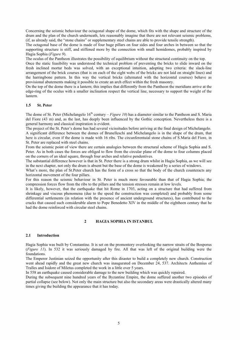
Concerning the seismic behaviour the octagonal shape of the dome, which fits with the shape and structure of the drum and the plan of the church underneath, lets reasonably imagine that there are not relevant seismic problems, (if, as already said, the “stone chains” or supplementary steel chains are able to provide tensile strength). The octagonal base of the dome is made of four huge pillars on four sides and four arches in between so that the supporting structure is stiff, and stiffened more by the connection with small hemidomes, probably inspired by Hagia Sophia (Figure 9). The oculus of the Pantheon illustrates the possibility of equilibrium without the structural continuity on the top. Once the static feasibility was understood the technical problem of preventing the bricks to slide inward on the fresh inclined mortar beds was solved, with an exceptional intuition, adopting two criteria: the slack-line arrangement of the brick courses (that is on each of the eight webs of the bricks are not laid on straight lines) and the harringbone pattern. In this way the vertical bricks (alternated with the horizontal courses) behave as provisional abutements making it possible to create an arch effect within the fresh masonry. On the top of the dome there is a lantern; this implies that differently from the Pantheon the meridians arrive at the edge-ring of the oculus with a smaller inclination respect the vertical line, necessary to support the weight of the lantern. 1.5 St. Peter The dome of St. Peter (Michelangelo 16th century – Figure 10) has a diameter similar to the Pantheon and S. Maria del Fiore (43 m) and, as the last, has deeply been influenced by the Gothic conception. Nevertheless there is a general harmony and classical inspiration is evident. The project of the St. Peter’s dome has had several vicissitudes before arriving at the final design of Michelangelo. A significant difference between the domes of Brunelleschi and Michelangelo is in the shape of the drum, that here is circular, even if the dome is made with 16 ribs. The circunferentuial stone chains of S.Maria del Fiore, in St. Peter are replaced with steel chains. From the seismic point of view there are certain analogies between the structural scheme of Hagia Sophia and S. Peter. As in both cases the forces are obliged to flow from the circular plane of the dome to four columns placed on the corners of an ideal square, through four arches and relative pendentives. The substantial difference however is that in St. Peter there is a strong drum whilst in Hagia Sophia, as we will see in the next chapter, not only the drum is absent but the base of the dome is weakened by a series of windows. What’s more, the plan of St.Peter church has the form of a cross so that the body of the church counteracts any horizontal movement of the four pillars. For this reason the seismic behaviour in St. Peter is much more favourable than that of Hagia Sophia; the compression forces flow from the ribs to the pillars and the tension stresses remain at low levels. It is likely, however, that the earthquake that hit Rome in 1703, acting on a structure that had suffered from shrinkage and viscous phenomena (due to the speed the construction was completed) and probably from some differential settlements (in relation with the presence of ancient underground structures), has contributed to the cracks that caused such considerable alarm to Pope Benedetto XIV in the middle of the eightheen century that he had the dome reinforced with circular steel chains.
2 HAGIA SOPHIA IN ISTANBUL 2.1 Introduction Hagia Sophia was built by Constantine. It is set on the promontory overlooking the narrow straits of the Bosporus (Figure 11). In 532 it was seriously damaged by fire. All that was left of the original building were the foundations. The Emperor Justinian seized the opportunity after this disaster to build a completely new church. Construction went ahead rapidly and the great new church was inaugurated on December 24, 537. Architects Anthemius of Tralles and Isidore of Miletus completed the work in a little over 5 years. In 558 an earthquake caused considerable damage to the new building which was quickly repaired. During the subsequent nine hundred years of the Byzantine Empire, the dome suffered another two episodes of partial collapse (see below). Not only the main structure but also the secondary areas were drastically altered many times giving the building the appearance that it has today.
6
Fig. 9 – Small hemidomes which stabilise the structure of St. Mary Fig. 10 – St. Peter
Fig. 11 – Axonometric mesh of the structure of Hagia
Sophia (Federico Croci)
Fig. 12 – The dome, the pendentives and the arches which
support the dome
7
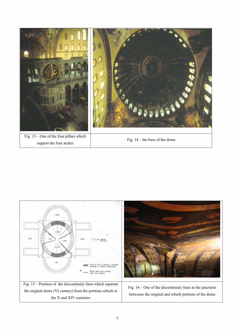
Fig. 13 – One of the four pillars which
support the four arches Fig. 14 – the base of the dome
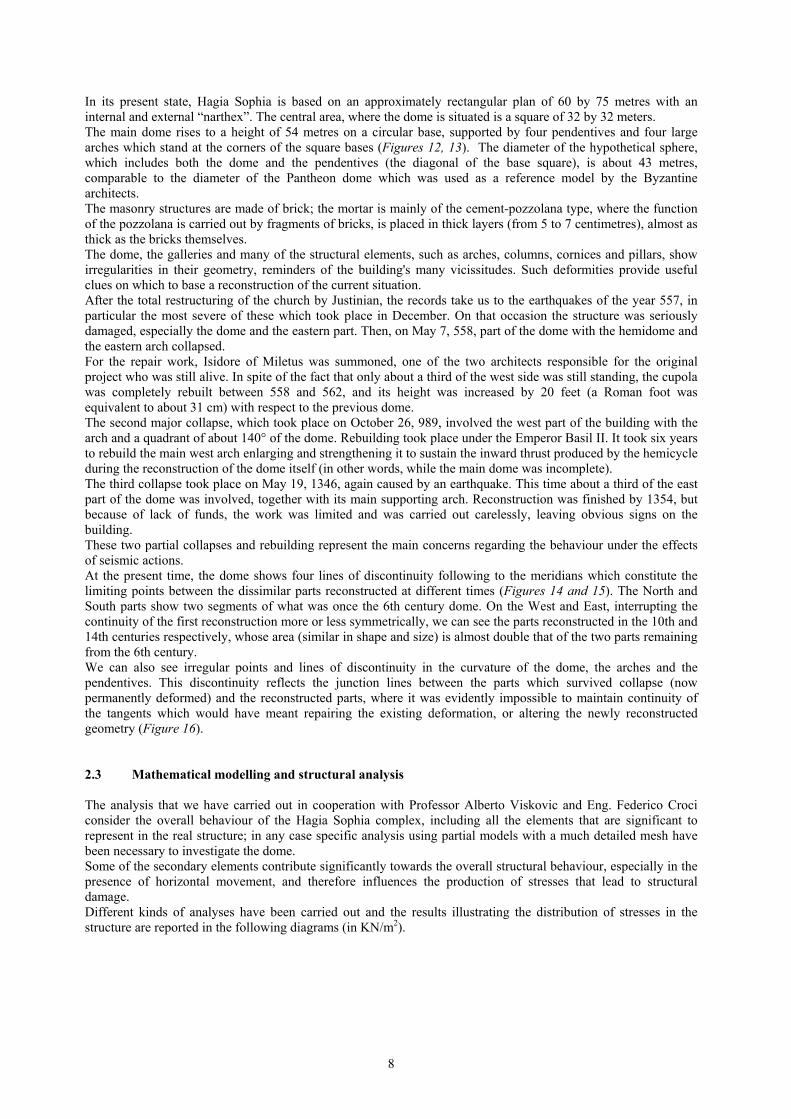
Fig. 15 – Position of the discontinuity lines which separate
the original dome (VI century) from the portions rebuilt in
the X and XIV centuries
Fig. 16 – One of the discontinuity lines in the junctions
betweens the original and rebuilt portions of the dome
8
In its present state, Hagia Sophia is based on an approximately rectangular plan of 60 by 75 metres with an internal and external “narthex”. The central area, where the dome is situated is a square of 32 by 32 meters. The main dome rises to a height of 54 metres on a circular base, supported by four pendentives and four large arches which stand at the corners of the square bases (Figures 12, 13). The diameter of the hypothetical sphere, which includes both the dome and the pendentives (the diagonal of the base square), is about 43 metres, comparable to the diameter of the Pantheon dome which was used as a reference model by the Byzantine architects. The masonry structures are made of brick; the mortar is mainly of the cement-pozzolana type, where the function of the pozzolana is carried out by fragments of bricks, is placed in thick layers (from 5 to 7 centimetres), almost as thick as the bricks themselves. The dome, the galleries and many of the structural elements, such as arches, columns, cornices and pillars, show irregularities in their geometry, reminders of the building's many vicissitudes. Such deformities provide useful clues on which to base a reconstruction of the current situation. After the total restructuring of the church by Justinian, the records take us to the earthquakes of the year 557, in particular the most severe of these which took place in December. On that occasion the structure was seriously damaged, especially the dome and the eastern part. Then, on May 7, 558, part of the dome with the hemidome and the eastern arch collapsed. For the repair work, Isidore of Miletus was summoned, one of the two architects responsible for the original project who was still alive. In spite of the fact that only about a third of the west side was still standing, the cupola was completely rebuilt between 558 and 562, and its height was increased by 20 feet (a Roman foot was equivalent to about 31 cm) with respect to the previous dome. The second major collapse, which took place on October 26, 989, involved the west part of the building with the arch and a quadrant of about 140° of the dome. Rebuilding took place under the Emperor Basil II. It took six years to rebuild the main west arch enlarging and strengthening it to sustain the inward thrust produced by the hemicycle during the reconstruction of the dome itself (in other words, while the main dome was incomplete). The third collapse took place on May 19, 1346, again caused by an earthquake. This time about a third of the east part of the dome was involved, together with its main supporting arch. Reconstruction was finished by 1354, but because of lack of funds, the work was limited and was carried out carelessly, leaving obvious signs on the building. These two partial collapses and rebuilding represent the main concerns regarding the behaviour under the effects of seismic actions. At the present time, the dome shows four lines of discontinuity following to the meridians which constitute the limiting points between the dissimilar parts reconstructed at different times (Figures 14 and 15). The North and South parts show two segments of what was once the 6th century dome. On the West and East, interrupting the continuity of the first reconstruction more or less symmetrically, we can see the parts reconstructed in the 10th and 14th centuries respectively, whose area (similar in shape and size) is almost double that of the two parts remaining from the 6th century. We can also see irregular points and lines of discontinuity in the curvature of the dome, the arches and the pendentives. This discontinuity reflects the junction lines between the parts which survived collapse (now permanently deformed) and the reconstructed parts, where it was evidently impossible to maintain continuity of the tangents which would have meant repairing the existing deformation, or altering the newly reconstructed geometry (Figure 16). 2.3 Mathematical modelling and structural analysis The analysis that we have carried out in cooperation with Professor Alberto Viskovic and Eng. Federico Croci consider the overall behaviour of the Hagia Sophia complex, including all the elements that are significant to represent in the real structure; in any case specific analysis using partial models with a much detailed mesh have been necessary to investigate the dome. Some of the secondary elements contribute significantly towards the overall structural behaviour, especially in the presence of horizontal movement, and therefore influences the production of stresses that lead to structural damage. Different kinds of analyses have been carried out and the results illustrating the distribution of stresses in the structure are reported in the following diagrams (in KN/m2).
9
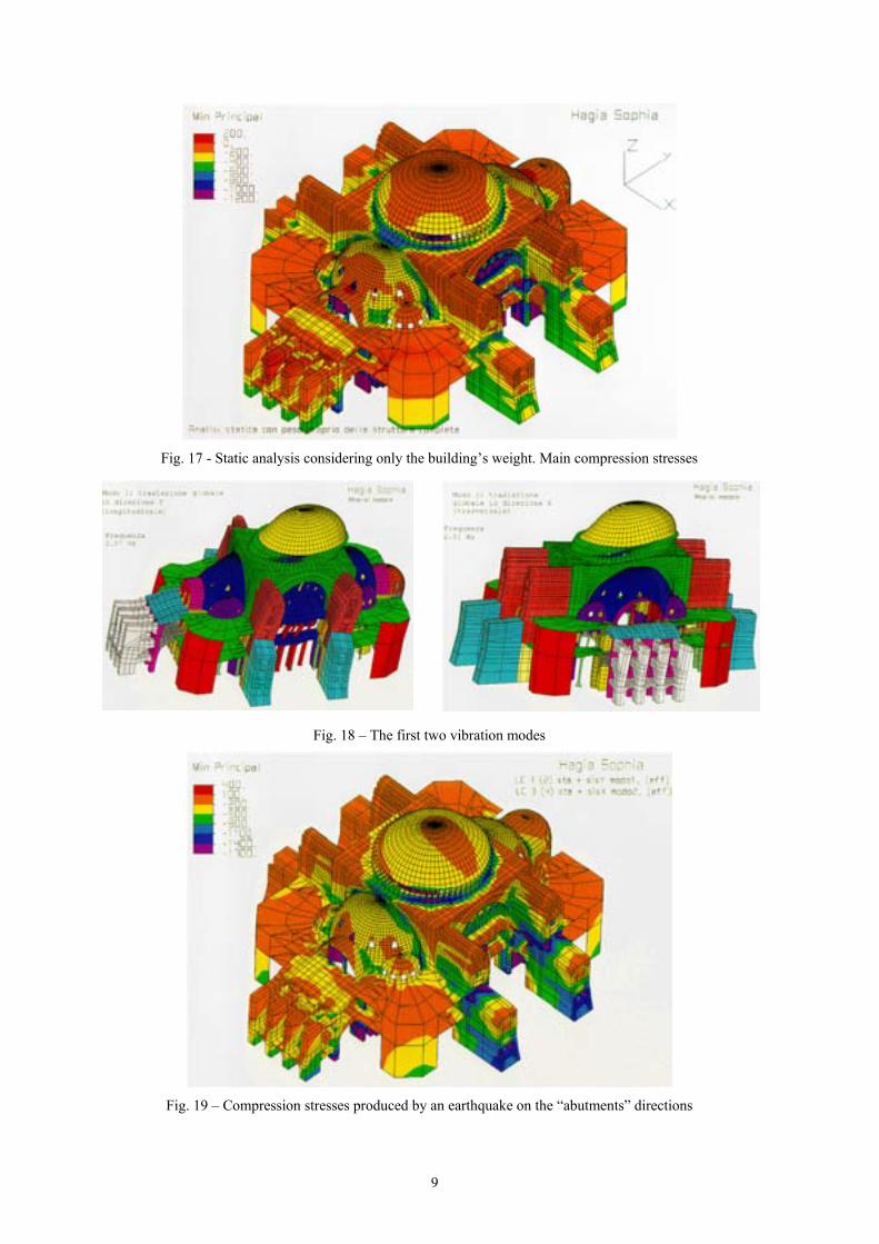
Fig. 17 - Static analysis considering only the building’s weight. Main compression stresses
Fig. 18 – The first two vibration modes
Fig. 19 – Compression stresses produced by an earthquake on the “abutments” directions
10
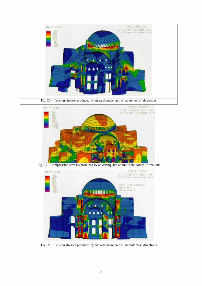
Fig. 20 – Tension stresses produced by an earthquake on the “abutements” directions
Fig. 21 – Compression stresses produced by an earthquake on the “hemidomes” directions
Fig. 22 – Tension stresses produced by an earthquake on the “hemidomes” directions
11
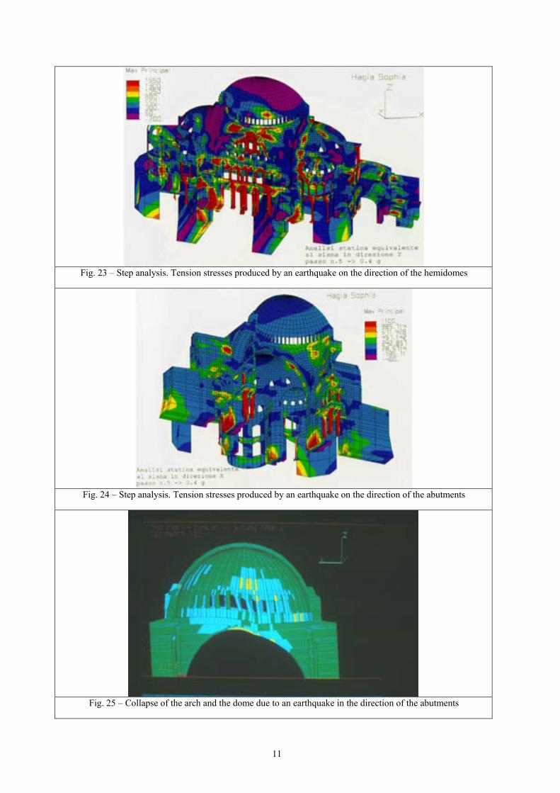
Fig. 23 – Step analysis. Tension stresses produced by an earthquake on the direction of the hemidomes
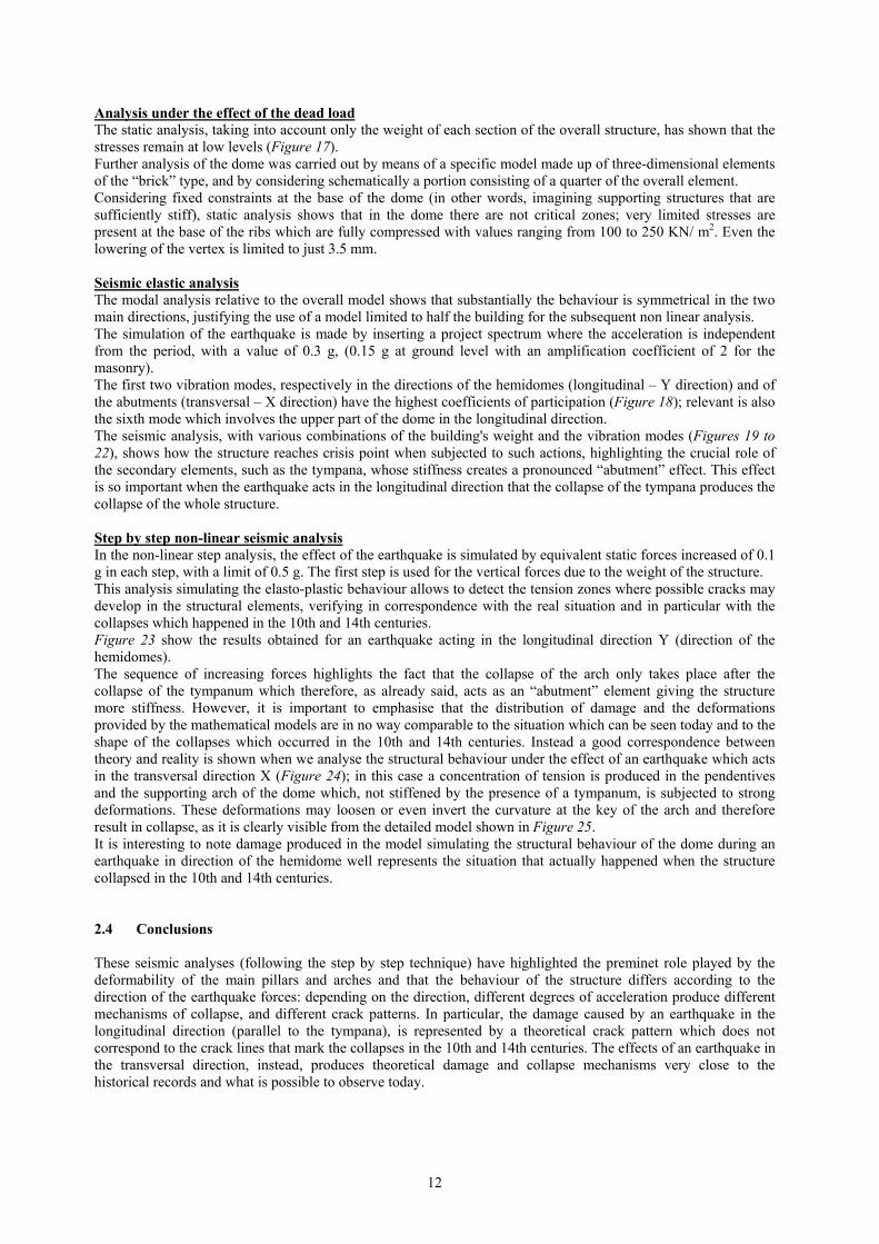
Fig. 24 – Step analysis. Tension stresses produced by an earthquake on the direction of the abutments
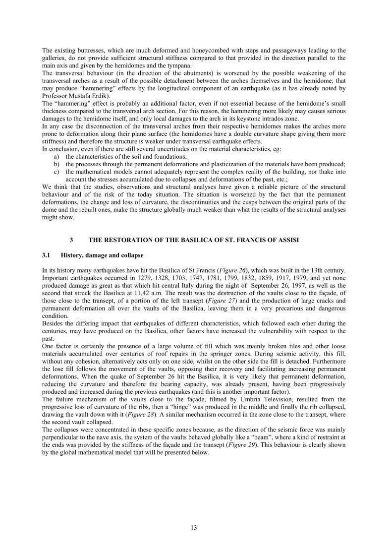
Fig. 25 – Collapse of the arch and the dome due to an earthquake in the direction of the abutments
12
Analysis under the effect of the dead load The static analysis, taking into account only the weight of each section of the overall structure, has shown that the stresses remain at low levels (Figure 17). Further analysis of the dome was carried out by means of a specific model made up of three-dimensional elements of the “brick” type, and by considering schematically a portion consisting of a quarter of the overall element. Considering fixed constraints at the base of the dome (in other words, imagining supporting structures that are sufficiently stiff), static analysis shows that in the dome there are not critical zones; very limited stresses are present at the base of the ribs which are fully compressed with values ranging from 100 to 250 KN/ m2. Even the lowering of the vertex is limited to just 3.5 mm. Seismic elastic analysis The modal analysis relative to the overall model shows that substantially the behaviour is symmetrical in the two main directions, justifying the use of a model limited to half the building for the subsequent non linear analysis. The simulation of the earthquake is made by inserting a project spectrum where the acceleration is independent from the period, with a value of 0.3 g, (0.15 g at ground level with an amplification coefficient of 2 for the masonry). The first two vibration modes, respectively in the directions of the hemidomes (longitudinal – Y direction) and of the abutments (transversal – X direction) have the highest coefficients of participation (Figure 18); relevant is also the sixth mode which involves the upper part of the dome in the longitudinal direction. The seismic analysis, with various combinations of the building's weight and the vibration modes (Figures 19 to 22), shows how the structure reaches crisis point when subjected to such actions, highlighting the crucial role of the secondary elements, such as the tympana, whose stiffness creates a pronounced “abutment” effect. This effect is so important when the earthquake acts in the longitudinal direction that the collapse of the tympana produces the collapse of the whole structure. Step by step non-linear seismic analysis In the non-linear step analysis, the effect of the earthquake is simulated by equivalent static forces increased of 0.1 g in each step, with a limit of 0.5 g. The first step is used for the vertical forces due to the weight of the structure. This analysis simulating the elasto-plastic behaviour allows to detect the tension zones where possible cracks may develop in the structural elements, verifying in correspondence with the real situation and in particular with the collapses which happened in the 10th and 14th centuries. Figure 23 show the results obtained for an earthquake acting in the longitudinal direction Y (direction of the hemidomes). The sequence of increasing forces highlights the fact that the collapse of the arch only takes place after the collapse of the tympanum which therefore, as already said, acts as an “abutment” element giving the structure more stiffness. However, it is important to emphasise that the distribution of damage and the deformations provided by the mathematical models are in no way comparable to the situation which can be seen today and to the shape of the collapses which occurred in the 10th and 14th centuries. Instead a good correspondence between theory and reality is shown when we analyse the structural behaviour under the effect of an earthquake which acts in the transversal direction X (Figure 24); in this case a concentration of tension is produced in the pendentives and the supporting arch of the dome which, not stiffened by the presence of a tympanum, is subjected to strong deformations. These deformations may loosen or even invert the curvature at the key of the arch and therefore result in collapse, as it is clearly visible from the detailed model shown in Figure 25. It is interesting to note damage produced in the model simulating the structural behaviour of the dome during an earthquake in direction of the hemidome well represents the situation that actually happened when the structure collapsed in the 10th and 14th centuries. 2.4 Conclusions These seismic analyses (following the step by step technique) have highlighted the preminet role played by the deformability of the main pillars and arches and that the behaviour of the structure differs according to the direction of the earthquake forces: depending on the direction, different degrees of acceleration produce different mechanisms of collapse, and different crack patterns. In particular, the damage caused by an earthquake in the longitudinal direction (parallel to the tympana), is represented by a theoretical crack pattern which does not correspond to the crack lines that mark the collapses in the 10th and 14th centuries. The effects of an earthquake in the transversal direction, instead, produces theoretical damage and collapse mechanisms very close to the historical records and what is possible to observe today.
13
The existing buttresses, which are much deformed and honeycombed with steps and passageways leading to the galleries, do not provide sufficient structural stiffness compared to that provided in the direction parallel to the main axis and given by the hemidomes and the tympana. The transversal behaviour (in the direction of the abutments) is worsened by the possible weakening of the transversal arches as a result of the possible detachment between the arches themselves and the hemidome; that may produce “hammering” effects by the longitudinal component of an earthquake (as it has already noted by Professor Mustafa Erdik). The “hammering” effect is probably an additional factor, even if not essential because of the hemidome’s small thickness compared to the transversal arch section. For this reason, the hammering more likely may causes serious damages to the hemidome itself, and only local damages to the arch in its keystone intrados zone. In any case the disconnection of the transversal arches from their respective hemidomes makes the arches more prone to deformation along their plane surface (the hemidomes have a double curvature shape giving them more stiffness) and therefore the structure is weaker under transversal earthquake effects. In conclusion, even if there are still several uncertitudes on the material characteristics, eg:
a) the characteristics of the soil and foundations; b) the processes through the permanent deformations and plasticization of the materials have been produced; c) the mathematical models cannot adequately represent the complex reality of the building, nor thake into
account the stresses accumulated due to collapses and deformations of the past, etc.; We think that the studies, observations and structural analyses have given a reliable picture of the structural behaviour and of the risk of the today situation. The situation is worsened by the fact that the permanent deformations, the change and loss of curvature, the discontinuities and the cusps between the original parts of the dome and the rebuilt ones, make the structure globally much weaker than what the results of the structural analyses might show.
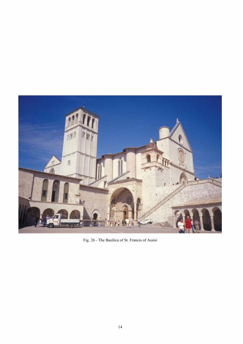
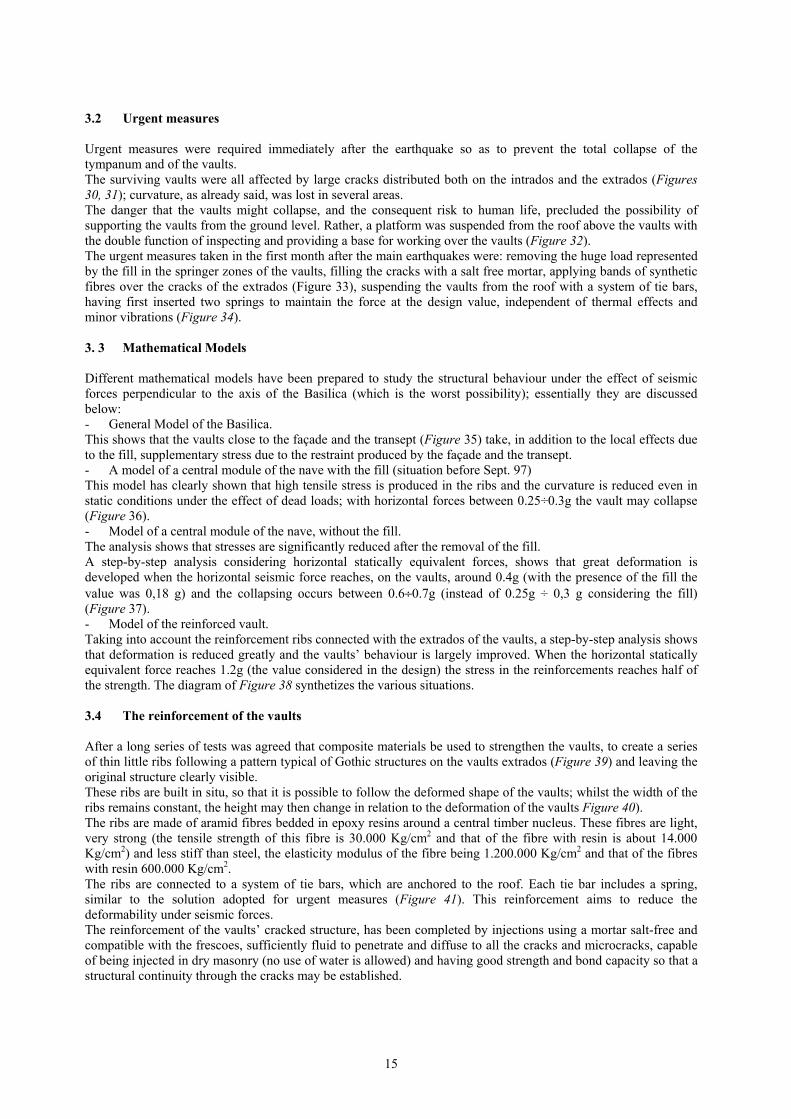
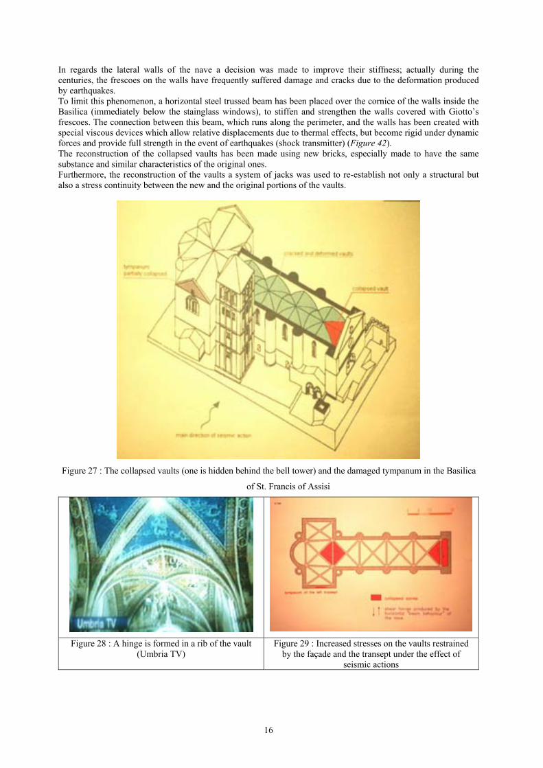
3 THE RESTORATION OF THE BASILICA OF ST. FRANCIS OF ASSISI 3.1 History, damage and collapse In its history many earthquakes have hit the Basilica of St Francis (Figure 26), which was built in the 13th century. Important earthquakes occurred in 1279, 1328, 1703, 1747, 1781, 1799, 1832, 1859, 1917, 1979, and yet none produced damage as great as that which hit central Italy during the night of September 26, 1997, as well as the second that struck the Basilica at 11,42 a.m. The result was the destruction of the vaults close to the façade, of those close to the transept, of a portion of the left transept (Figure 27) and the production of large cracks and permanent deformation all over the vaults of the Basilica, leaving them in a very precarious and dangerous condition. Besides the differing impact that earthquakes of different characteristics, which followed each other during the centuries, may have produced on the Basilica, other factors have increased the vulnerability with respect to the past. One factor is certainly the presence of a large volume of fill which was mainly broken tiles and other loose materials accumulated over centuries of roof repairs in the springer zones. During seismic activity, this fill, without any cohesion, alternatively acts only on one side, whilst on the other side the fill is detached. Furthermore the lose fill follows the movement of the vaults, opposing their recovery and facilitating increasing permanent deformations. When the quake of September 26 hit the Basilica, it is very likely that permanent deformation, reducing the curvature and therefore the bearing capacity, was already present, having been progressively produced and increased during the previous earthquakes (and this is another important factor). The failure mechanism of the vaults close to the façade, filmed by Umbria Television, resulted from the progressive loss of curvature of the ribs, then a “hinge” was produced in the middle and finally the rib collapsed, drawing the vault down with it (Figure 28). A similar mechanism occurred in the zone close to the transept, where the second vault collapsed. The collapses were concentrated in these specific zones because, as the direction of the seismic force was mainly perpendicular to the nave axis, the system of the vaults behaved globally like a “beam”, where a kind of restraint at the ends was provided by the stiffness of the façade and the transept (Figure 29). This behaviour is clearly shown by the global mathematical model that will be presented below.
14
Fig. 26 - The Basilica of St. Francis of Assisi
15
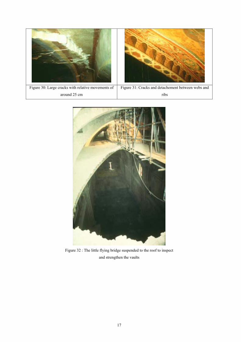
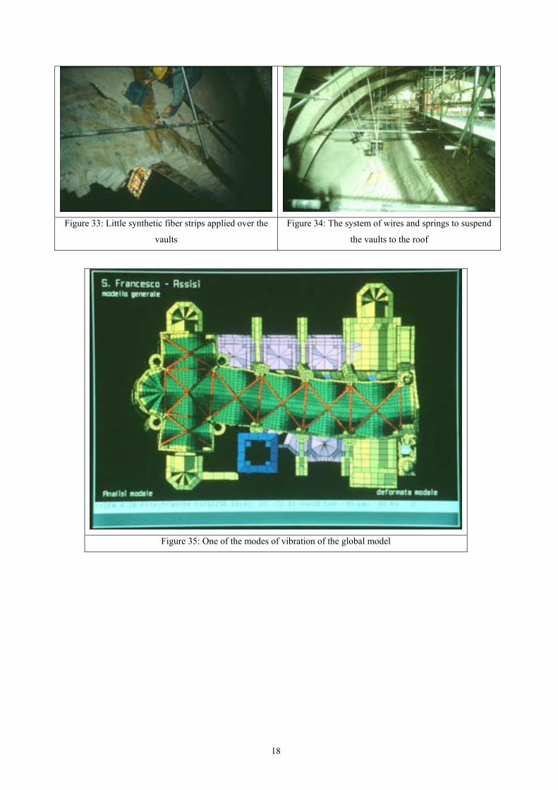
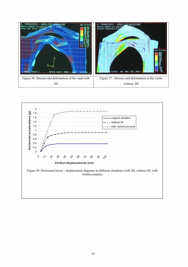
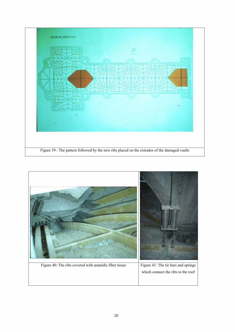
3.2 Urgent measures Urgent measures were required immediately after the earthquake so as to prevent the total collapse of the tympanum and of the vaults. The surviving vaults were all affected by large cracks distributed both on the intrados and the extrados (Figures 30, 31); curvature, as already said, was lost in several areas. The danger that the vaults might collapse, and the consequent risk to human life, precluded the possibility of supporting the vaults from the ground level. Rather, a platform was suspended from the roof above the vaults with the double function of inspecting and providing a base for working over the vaults (Figure 32). The urgent measures taken in the first month after the main earthquakes were: removing the huge load represented by the fill in the springer zones of the vaults, filling the cracks with a salt free mortar, applying bands of synthetic fibres over the cracks of the extrados (Figure 33), suspending the vaults from the roof with a system of tie bars, having first inserted two springs to maintain the force at the design value, independent of thermal effects and minor vibrations (Figure 34). 3. 3 Mathematical Models Different mathematical models have been prepared to study the structural behaviour under the effect of seismic forces perpendicular to the axis of the Basilica (which is the worst possibility); essentially they are discussed below: - General Model of the Basilica. This shows that the vaults close to the façade and the transept (Figure 35) take, in addition to the local effects due to the fill, supplementary stress due to the restraint produced by the façade and the transept. - A model of a central module of the nave with the fill (situation before Sept. 97) This model has clearly shown that high tensile stress is produced in the ribs and the curvature is reduced even in static conditions under the effect of dead loads; with horizontal forces between 0.25÷0.3g the vault may collapse (Figure 36). - Model of a central module of the nave, without the fill. The analysis shows that stresses are significantly reduced after the removal of the fill. A step-by-step analysis considering horizontal statically equivalent forces, shows that great deformation is developed when the horizontal seismic force reaches, on the vaults, around 0.4g (with the presence of the fill the value was 0,18 g) and the collapsing occurs between 0.6÷0.7g (instead of 0.25g ÷ 0,3 g considering the fill) (Figure 37). - Model of the reinforced vault. Taking into account the reinforcement ribs connected with the extrados of the vaults, a step-by-step analysis shows that deformation is reduced greatly and the vaults’ behaviour is largely improved. When the horizontal statically equivalent force reaches 1.2g (the value considered in the design) the stress in the reinforcements reaches half of the strength. The diagram of Figure 38 synthetizes the various situations. 3.4 The reinforcement of the vaults After a long series of tests was agreed that composite materials be used to strengthen the vaults, to create a series of thin little ribs following a pattern typical of Gothic structures on the vaults extrados (Figure 39) and leaving the original structure clearly visible. These ribs are built in situ, so that it is possible to follow the deformed shape of the vaults; whilst the width of the ribs remains constant, the height may then change in relation to the deformation of the vaults Figure 40). The ribs are made of aramid fibres bedded in epoxy resins around a central timber nucleus. These fibres are light, very strong (the tensile strength of this fibre is 30.000 Kg/cm2 and that of the fibre with resin is about 14.000 Kg/cm2) and less stiff than steel, the elasticity modulus of the fibre being 1.200.000 Kg/cm2 and that of the fibres with resin 600.000 Kg/cm2. The ribs are connected to a system of tie bars, which are anchored to the roof. Each tie bar includes a spring, similar to the solution adopted for urgent measures (Figure 41). This reinforcement aims to reduce the deformability under seismic forces. The reinforcement of the vaults’ cracked structure, has been completed by injections using a mortar salt-free and compatible with the frescoes, sufficiently fluid to penetrate and diffuse to all the cracks and microcracks, capable of being injected in dry masonry (no use of water is allowed) and having good strength and bond capacity so that a structural continuity through the cracks may be established.
16
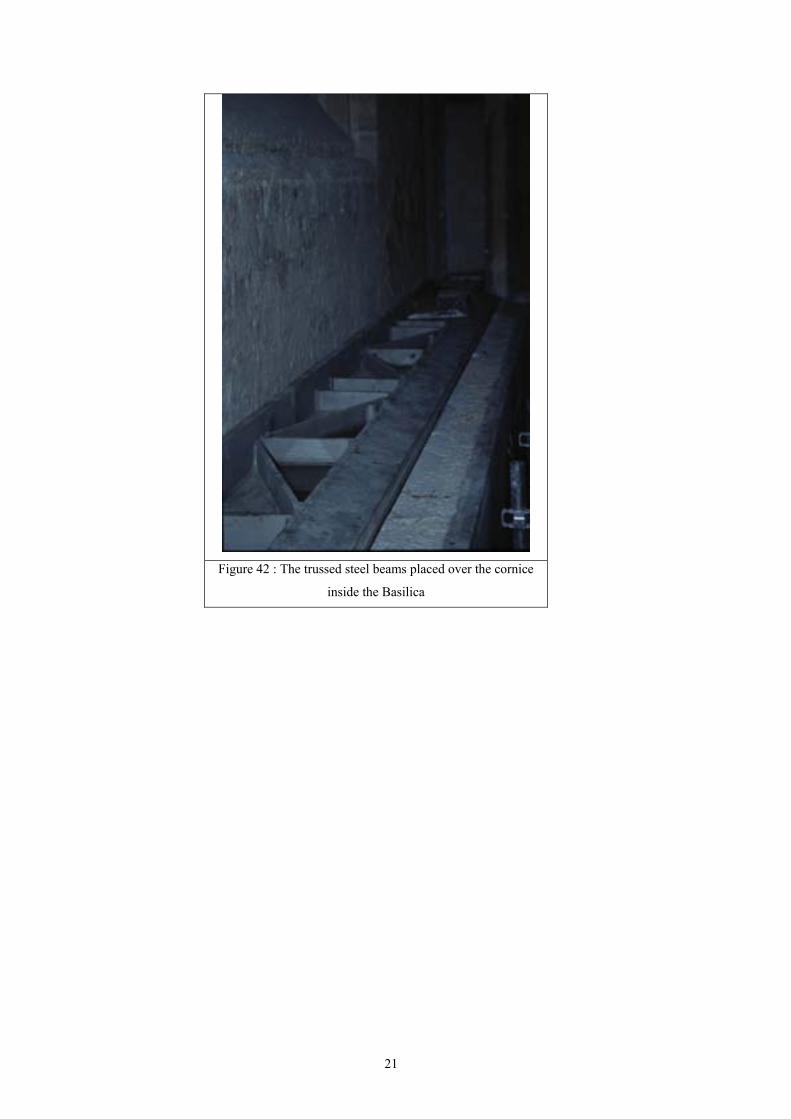
In regards the lateral walls of the nave a decision was made to improve their stiffness; actually during the centuries, the frescoes on the walls have frequently suffered damage and cracks due to the deformation produced by earthquakes. To limit this phenomenon, a horizontal steel trussed beam has been placed over the cornice of the walls inside the Basilica (immediately below the stainglass windows), to stiffen and strengthen the walls covered with Giotto’s frescoes. The connection between this beam, which runs along the perimeter, and the walls has been created with special viscous devices which allow relative displacements due to thermal effects, but become rigid under dynamic forces and provide full strength in the event of earthquakes (shock transmitter) (Figure 42). The reconstruction of the collapsed vaults has been made using new bricks, especially made to have the same substance and similar characteristics of the original ones. Furthermore, the reconstruction of the vaults a system of jacks was used to re-establish not only a structural but also a stress continuity between the new and the original portions of the vaults.
Figure 27 : The collapsed vaults (one is hidden behind the bell tower) and the damaged tympanum in the Basilica
of St. Francis of Assisi
Figure 28 : A hinge is formed in a rib of the vault (Umbria TV)
Figure 29 : Increased stresses on the vaults restrained by the façade and the transept under the effect of
seismic actions
17
Figure 30: Large cracks with relative movements of
around 25 cm
Figure 31: Cracks and detachement between webs and
ribs
Figure 32 : The little flying bridge suspended to the roof to inspect
and strengthen the vaults
18
Figure 33: Little synthetic fiber strips applied over the
vaults
Figure 34: The system of wires and springs to suspend
the vaults to the roof
Figure 35: One of the modes of vibration of the global model
19
Figure 36: Stresses and deformation of the vault with
fill
Figure 37 : Stresses and deformation in the vaults
without fill
0
0,2
0,4
0,6
0,8
1
1,2
1,4
1,6
1,8
2
0 10 20 30 40 50 60 70 80 90100
Vertical displacements [cm]
Ho
rizo
nta
l acc
eler
atio
ns
[g]
original situation
without fill
with reinforcem ents
Figure 38: Horizontal forces – displacement diagrams in different situations (with fill, without fill, with
reinforcements)
20
Figure 39 : The pattern followed by the new ribs placed on the extrados of the damaged vaults
Figure 40: The ribs covered with aramidic fiber tissue Figure 41: The tie bars and springs
which connect the ribs to the roof
21
Figure 42 : The trussed steel beams placed over the cornice
inside the Basilica


![Byzantium Revisited: The Mosaics of Hagia Sophia in the ...humanitiestjc.yolasite.com/resources/Evans_PallasLecture[1].pdf · 1 Byzantium Revisited: The Mosaics of Hagia Sophia in](https://img.pdfslide.us/doc/110x75/5af6ebe77f8b9a9e59900dda/byzantium-revisited-the-mosaics-of-hagia-sophia-in-the-1pdf1-byzantium-revisited.jpg)