Embed Size (px)
Citation preview
Engineering Structures 29 (2007) 213–223www.elsevier.com/locate/engstruct
Seismic analysis of wood building structures
Ashraf Ayoub
Department of Civil, Architectural, and Environmental Engineering, University of Missouri, Rolla, MO 65409, United States
Received 13 September 2005; received in revised form 16 December 2005; accepted 25 April 2006Available online 27 June 2006
Abstract
The objective of this work is to develop a new model for nonlinear seismic analysis of wood building structures. The proposed inelastic materialconstitutive laws used in the model incorporate different types of degradation, not available in previous work. This degrading behavior has beenobserved during experimental testing of these types of structure under severe loading conditions. The material parameters of the new degradingmodel are based on physical reasoning, and are calibrated from currently available experimental data. The proposed model could be easily addedto existing commercial finite element libraries, which can provide the user with a large variety of modeling capabilities. The study concludes witha correlation with experimentally tested specimens. Good agreement between analysis and tests was observed.c© 2006 Elsevier Ltd. All rights reserved.
Keywords: Wood buildings; Nonlinear analysis of timber structures; Seismic behavior of wood structures; Degrading constitutive laws; Peak-oriented models;Pinched hysteretic behavior
1. Introduction and literature review
Unlike steel or concrete structures, wood buildings lackproper understanding of their structural response, particularlyunder the effect of severe loading conditions, such as largeseismic excitations or hurricanes. This fact is supportedby many observed damages of wood structures after majorearthquakes such as Northridge in California, US, Kobe inJapan, and Chi Chi in Taiwan; or after major hurricanes suchas Ivan and Katrina which hit the Gulf coast of the US recently.For example, after the Northridge earthquake, the Los Angeleshousing department [1] reported that damage in woodframeconstruction resulted in 330,000 residential units sustainingsome damage, representing 90% of housing throughout allaffected areas. Among these, 65,000 units sustained majordamage, and 19,400 housing units were vacated, 92% ofwhich were located in multi-family buildings. The overallproperty damage loss was estimated at $20 million. It isstriking to realize that, in California, 99% of all residencesare of woodframe construction. Moreover, according to [2]:“the general range of the fraction of wood structures to totalstructures is between 80% and 90% in all regions of the US”.
E-mail address: [email protected].
0141-0296/$ - see front matter c© 2006 Elsevier Ltd. All rights reserved.doi:10.1016/j.engstruct.2006.04.011
In most woodframe structures, wood shear walls are themain structural element that resists lateral loads due to windand earthquakes. Several experimental and analytical studieson timber shear walls have been performed. Most of thesetests were performed for cyclic loading cases, and only a fewconsidered dynamic effects. Only recently, a research projectfunded by Federal Emergency Management Agency (FEMA)through the office of Emergency Management was conducted,where shake table tests of multi-story wood apartment buildingswere performed. The project is referred to as the CUREE-Caltech woodframe project in reference to the CaliforniaUniversities for Research in Earthquake Engineering (CUREE)and Caltech University. A literature review of previous work onwood structures is given next.
Several static and dynamic tests on wood shear walls aredocumented in the literature (e.g. [3–10]). In addition, a largeexperimental program at the University of California, Irvinewas conducted [11], where 36 8 ft by 8 ft timber shear wallswith different configurations were tested under reversed cyclicloading. The project was funded by the city of Los Angelesand FEMA in an effort to investigate current design codes fortimber structures after the 1994 Northridge earthquake. Thework was extended later for one-story and two-story shear wallswith different configurations and different finish materials, as apart of the CUREE-Caltech woodframe project, as describedin [12].
214 A. Ayoub / Engineering Structures 29 (2007) 213–223
Several tests were also conducted on full scale multi-storywood structures (e.g. [13–15]). In addition, a two-story woodstructure was tested recently using recorded data on a shaketable as a part of the CUREE-Caltech woodframe project [16].Furthermore, three shake table tests on a three-story apartmentbuilding with tuck-under parking were also conducted as a partof the project [17]. The tests investigated the effect of steelframe retrofit schemes around the parking openings, and theeffect of drywall finish materials. Also as a part of this project,a loading protocol for cyclic analysis of wood shear walls wasdeveloped [18].
Several numerical studies that attempted to model thenonlinear behavior of timber shear walls have been proposed. Asummary of the relevant ones is presented herein. Chehab [19]analyzed a two-story woodframe building using linear elasticmodels. Itani and Cheung [20], and Falk and Itani [21]developed a model using plane stress, beams and joint elementsto model the wall, studs and nails respectively. Simplenonlinear material models were used for the joint elements,while the beam and plane stress elements were assumed tobe elastic. Gupta and Kuo [22,23] developed a model forwoodframe buildings made up of seven super-elements, andhaving nine global degrees of freedom. The degrees of freedomrepresent the horizontal displacements of the top of the wallsand the roof, the vertical displacements of the walls, andthe vertical uplift. Stewart [24], Filiatrault [25], Kasal andLeichti [26], and Kasal and Xu [27] developed single degreeof freedom models that account for the overall behavior ofthe wall system. Foliente [28] also developed a single degreeof freedom to model the overall behavior of timber walls,and included pinching and strength and stiffness degradationeffects. Kasal et al. [29] used the ANSYS computer programto model a one-story timber structure. The nonlinearity of thewall was modeled using diagonal nonlinear spring element.Nails were modeled using bilinear spring elements. Kasalet al. [30] later extended their work, and conducted stochasticMonte Carlo simulations of 3D timber buildings, where thematerial properties and loads were treated probabilistically.Dolan [31], Dolan and Foschi [32], and White and Dolan [33]developed a model that consists of four subelements: anelastic beam element to model the studs, an elastic orthotropicelement to model the plywood shear wall, a nonlinear springelement to model nails, and a bilinear compression springwith gap to model bearing between adjacent walls. Davenneet al. [34] developed a 3D model for timber walls includingstrength degradation of the nails under repeated cyclic loading.Foschi [35] developed a diaphragm analysis program (DAP-3D) to analyze wood houses subjected to wind loads. Thelinear elastic model was later extended [36] to include pinchingeffects of nails. Most recently, He et al. [37] extended the samemodel and developed the computer program LightFrame3D.The model consists of a thin plate element to model theplywood, a beam element to model the studs, and a nonlinearspring element to model the nails and surrounding wood.Shear and pullout behavior of nails is included using apinched hysteretic model. The model was used to analyzea one-story timber wall system with opening under cyclic
loading. Folz and Filiatrault [38,39] developed a computerprogram for cyclic analysis of wood shear walls (CASHEW).The model is based on rigid frame members, and linearelastic sheathing panels, and assumes nonlinear behavior forthe nails following the single degree of freedom model byFiliatrault [25]. Only deformation-based stiffness degradationwas included in this model. The work was a part of theCUREE-Caltech woodframe project. The authors developedalso a simplified program (SAWS) [40] for seismic analysisof woodframe structures. The program is composed of rigiddiaphragms and zero-height nonlinear spring elements to modelthe inelastic behavior of shear walls. The material propertiesof the spring elements follow the same pinched hystereticbehavior of the CASHEW model. The SAWS model wasused to simulate the dynamic behavior of a two-story timberstructure tested on the shake table at UC-San Diego [41] underdifferent earthquakes including a near-source record. The teststructure was used earlier for a blind prediction competition bythe earthquake engineering community [42]. Five participantscontributed to the competition. The first team used the frameanalysis program Drain-3D [43] to model the structure. Theymodeled the structure as a 3D frame with rigid members androtational pinched inelastic springs to model the shear walls.The pinched model did not account for degradation though.The second team developed a 3D model with equivalent trussesto represent the shear wall panels. The third team used theRUAUMOKO package [44], and modeled the structure withelastic quadrilateral finite elements for the shear wall andinelastic pinched springs at the corners of the panels. Theirmodel significantly underestimated the response of the structurethough. The fourth team used the DRAIN-2DX [43] programwith elastic panel elements and pinched inelastic springsto model each shear wall behavior. The structural analysisprogram CANNY-E [45] was then used for the 3D analysis withrigid floors and braced frames with pinched characteristics tomodel the shear walls. The fifth team used the program ISTAR-WD [46] to estimate the inelastic shear wall behavior. Thefinite element program SAP 2000 [47] was the used to conductthe 3D analysis using rigid shell elements and inelastic springelements to model the shear walls. The characteristics of thespring elements were obtained from the ISTAR-WD results, butdo not consider pinching effects. The error reported in all thesemodels varied from 1% up to 77% but the lessons learned fromthe studies were of great value.
Most previous models cannot be developed by modificationof existing finite element packages, as they are consideredin-house software programs designed specifically for woodstructures. In addition, while these models can provide areasonable estimate of the inelastic deformation of timberstructures, they do not consider all types of degradationsimultaneously, an important parameter affecting the behaviorof timber structures particularly those near collapse. Themodels by Itani, Kasal, Dolan, and Foschi do not considerany type of degradation, but consider pinching effects ofnails only. The model by Filiatrault considers only stiffnessdegradation, while the one by Davenne considers onlystrength degradation. Both models do not account for strength
A. Ayoub / Engineering Structures 29 (2007) 213–223 215
softening behavior or for nail pullout. Furthermore, degradationparameters do not in general follow physical reasoning. Inconclusion, most developed numerical models to date donot account for all types of degradation that are observedin the hysteretic response of timber structures, and are notavailable for practical use by researchers in the field. Theobjective of this work is to develop a new model for seismicanalysis of wood structures that can provide the user withaccuracy as well as flexibility in modeling. Developmentof the model starts by considering wood shear wallconfigurations.
2. Wood shear wall configuration and observed behavior
A typical wood shear wall system consists of three maincomponents:(a) Framing members, which are vertical studs, and horizontalplates and sills.(b) Sheathing panels, which are made of plywood, orientedstrand boards, or any other structural panel materials.(c) Connectors to connect the framing members to the sheathingpanels. The most commonly used connectors are dowel-typefasteners such as nails. Nails are typically spaced at regularintervals, but are usually more dense around the perimeter ofthe panels. In addition, hold-down devices such as anchor boltsare usually provided to provide additional connection betweenstud members and sill plates.
The load–deformation response of wood shear walls ishighly nonlinear and is governed by the nonlinear behaviorof the fasteners, which exhibit a degrading pinched hystereticbehavior under cyclic load reversals. The monotonic envelope,as observed in experimental testing, exhibits strength softeningat high deformation levels, also known as capping. Severaltypes of cyclic degradation have also been observed inexperimental testing: strength degradation, where the yieldforce decreases as a function of the number of cycles;unloading stiffness degradation, where the unloading stiffnessalso decreases as a function of the number of cycles; acceleratedstiffness degradation, where the reloading target stiffnessdecreases; and cap degradation, where the onset of strengthsoftening is reached earlier. The goal of this work is to developa numerical model that captures as accurately as possible thenonlinear cyclic behavior of wood structures, including alltypes of degradation. The proposed model for a typical shearwall component is described next. Global analysis of woodbuilding systems will be described in subsequent sections.
3. Proposed numerical model for wood shear walls
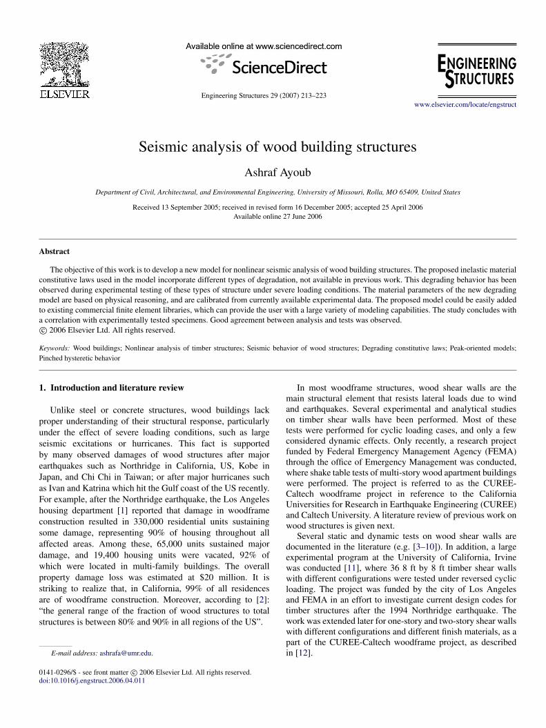
The proposed numerical model for wood shear walls asshown in Fig. 1 was developed using the finite element packageDIANA (Displacement Analyzer) [48], and consists of:
(a) An elastic shell element to model the plywood shear wall,(b) Elastic beam elements to model the studs, and top and
bottom plates, and(c) Nonlinear degrading distributed interface elements to
model the nails.
Fig. 1. Finite element model for wood shear walls.
The shell element is a quadrilateral four-node isoparametricelement. The bending behavior includes transverse sheardeformation following the Mindlin theory. The shell elementhas five degrees of freedom: three translations and tworotations; and it has no drilling out-of-plane rotations. Thebeam element is a 3D two-node linear elastic element. Boththe shell and beam elements already exist in the commercialversion of DIANA. The interface element is a distributed line-element oriented in three dimensions to model the nail pulloutand nail shear in two directions. The shear behavior in eachdirection is assumed to be independent of the behavior inthe other direction; however, future studies will be conductedto address this effect. The nail pullout behavior is assumedto be elastic, while the nail shear in both directions isassumed to follow a degrading pinched hysteretic behavior.The distributed model was selected in this study over discretemodels due to its simplicity for the user. The parameters of thedistributed interface element are defined using individual nailproperties divided by the nail spacing. The proposed degradingconstitutive model was added to the DIANA material library,and is described next.
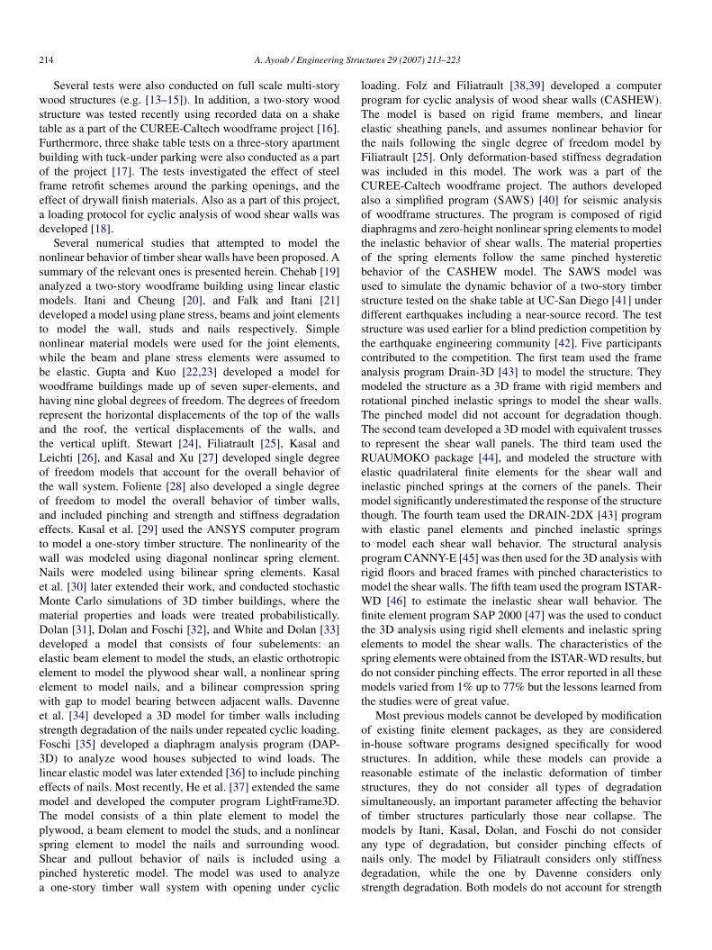
4. Degrading pinching model
The degrading pinching model is used for the continuousinterface link element that describes nail shear behavior andhas been added to the DIANA material library. The modelassumes a bilinear backbone curve for numerical efficiency. Thepinching model follows the peak oriented, stiffness degradingmodel as described by Clough [49], except that typicalreloading consists of two branches. First, reloading is directedtowards a point defined by the maximum displacement in theresponse history and a reduced target force. This branch definesthe path until the displacement attains a specified value δpinch,as described later. Thereafter, the reloading branch is directedtowards the previous maximum peak point as shown in Fig. 2.
The model is modified by introducing a cap, which isa softening branch that models strength deterioration undermonotonic loading. The cap of the skeleton curve is defined bythe cap displacement in tension and compression, and the capnegative stiffness.
216 A. Ayoub / Engineering Structures 29 (2007) 213–223
Fig. 2. Pinching model.
Fig. 3. Unloading–reloading for pinching model.
4.1. Unloading–reloading rules
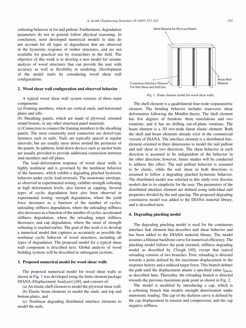
As mentioned in the previous paragraph, typical reloadingis first directed towards a point defined by the maximumdisplacement and a reduced target force. The reduced targetforce equals a constant factor of the maximum force κ fmax.The displacement until which this branch is attained, δpinch,shown in Fig. 3, equals a constant factor of the permanentdisplacement of the largest previous excursion αpinchδpermanent.If the reloading displacement is smaller than αpinchδpermanent,reloading consists of a single branch and is directed towards theprevious maximum peak as shown in Fig. 3, much more like aClough type model.
4.2. Degradation
It is well known from experimental evidence that anymaterial deteriorates as a function of the loading history. Everyinelastic excursion causes damage and the damage accumulatesas the number of excursions increases. Therefore it is necessaryto include degradation effects in modeling hysteretic behavior.
Four types of degradation are included in the model asobserved in experiments: Strength degradation, Unloadingstiffness degradation, Accelerated stiffness degradation, andCap degradation. The model uses energy criteria characterizedby simple physical properties to consider degradation effects.The model is based on the work proposed by Rahnama andKrawinkler [50].
4.2.1. Strength degradationStrength degradation refers to the decrease of the yield
strength value as a function of the loading history. The strengthdegradation parameter used in this study is energy dependent,and is derived by considering the following expression:
F iy = F i−1
y (1 − β istr) (1)
where F iy is the yield strength at the current excursion i , F i−1
y
is the yield strength at the previous excursion i − 1, and β istr is
a scalar parameter, ranging between 0 and 1, that accounts fordegradation effects at the current excursion i . The parameterβ i
str is determined as follows:
A. Ayoub / Engineering Structures 29 (2007) 213–223 217
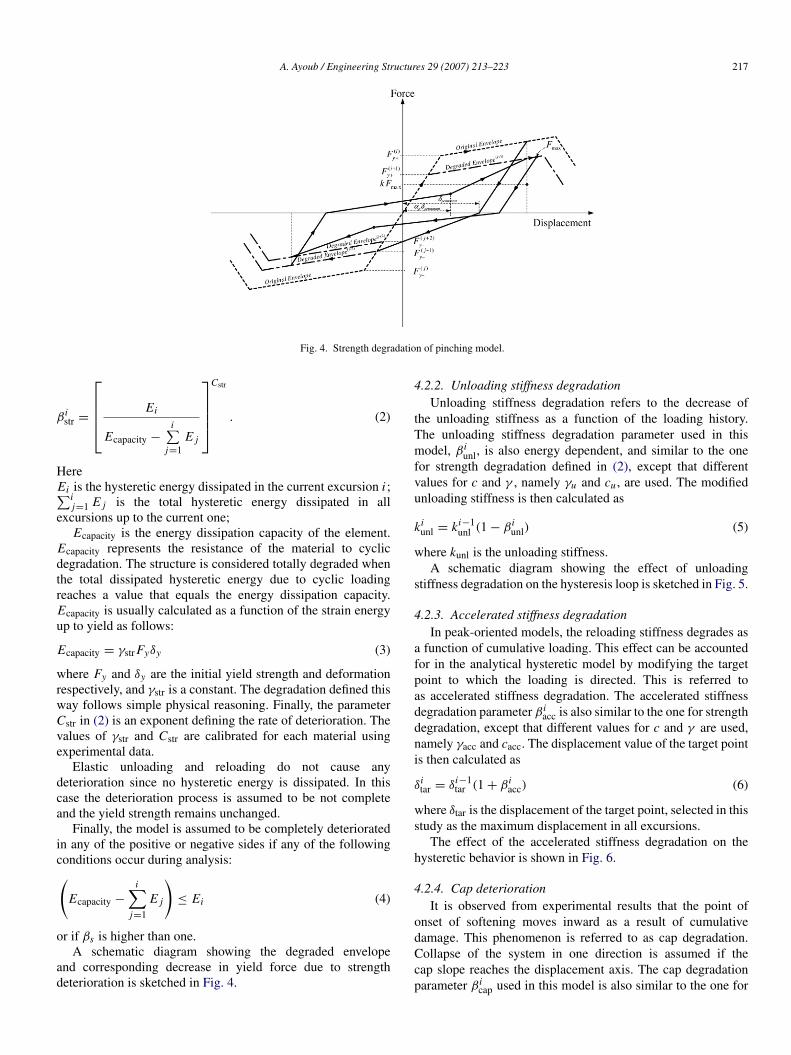
Fig. 4. Strength degradation of pinching model.
β istr =
Ei
Ecapacity −
i∑j=1
E j
Cstr
. (2)
HereEi is the hysteretic energy dissipated in the current excursion i ;∑i
j=1 E j is the total hysteretic energy dissipated in allexcursions up to the current one;
Ecapacity is the energy dissipation capacity of the element.Ecapacity represents the resistance of the material to cyclicdegradation. The structure is considered totally degraded whenthe total dissipated hysteretic energy due to cyclic loadingreaches a value that equals the energy dissipation capacity.Ecapacity is usually calculated as a function of the strain energyup to yield as follows:
Ecapacity = γstr Fyδy (3)
where Fy and δy are the initial yield strength and deformationrespectively, and γstr is a constant. The degradation defined thisway follows simple physical reasoning. Finally, the parameterCstr in (2) is an exponent defining the rate of deterioration. Thevalues of γstr and Cstr are calibrated for each material usingexperimental data.
Elastic unloading and reloading do not cause anydeterioration since no hysteretic energy is dissipated. In thiscase the deterioration process is assumed to be not completeand the yield strength remains unchanged.
Finally, the model is assumed to be completely deterioratedin any of the positive or negative sides if any of the followingconditions occur during analysis:(
Ecapacity −
i∑j=1
E j
)≤ Ei (4)
or if βs is higher than one.A schematic diagram showing the degraded envelope
and corresponding decrease in yield force due to strengthdeterioration is sketched in Fig. 4.
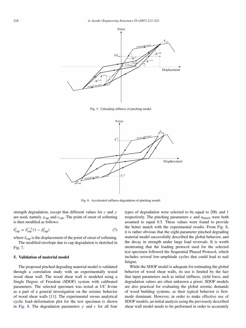
4.2.2. Unloading stiffness degradationUnloading stiffness degradation refers to the decrease of
the unloading stiffness as a function of the loading history.The unloading stiffness degradation parameter used in thismodel, β i
unl, is also energy dependent, and similar to the onefor strength degradation defined in (2), except that differentvalues for c and γ , namely γu and cu , are used. The modifiedunloading stiffness is then calculated as
kiunl = ki−1
unl (1 − β iunl) (5)
where kunl is the unloading stiffness.A schematic diagram showing the effect of unloading
stiffness degradation on the hysteresis loop is sketched in Fig. 5.
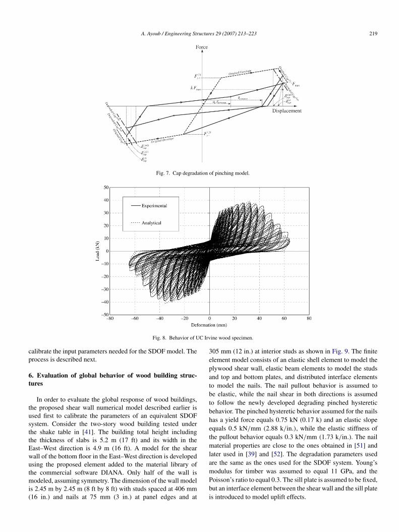
4.2.3. Accelerated stiffness degradationIn peak-oriented models, the reloading stiffness degrades as
a function of cumulative loading. This effect can be accountedfor in the analytical hysteretic model by modifying the targetpoint to which the loading is directed. This is referred toas accelerated stiffness degradation. The accelerated stiffnessdegradation parameter β i
acc is also similar to the one for strengthdegradation, except that different values for c and γ are used,namely γacc and cacc. The displacement value of the target pointis then calculated as
δitar = δi−1
tar (1 + β iacc) (6)
where δtar is the displacement of the target point, selected in thisstudy as the maximum displacement in all excursions.
The effect of the accelerated stiffness degradation on thehysteretic behavior is shown in Fig. 6.
4.2.4. Cap deteriorationIt is observed from experimental results that the point of
onset of softening moves inward as a result of cumulativedamage. This phenomenon is referred to as cap degradation.Collapse of the system in one direction is assumed if thecap slope reaches the displacement axis. The cap degradationparameter β i
cap used in this model is also similar to the one for
218 A. Ayoub / Engineering Structures 29 (2007) 213–223
Fig. 5. Unloading stiffness of pinching model.
Fig. 6. Accelerated stiffness degradation of pinching model.
strength degradation, except that different values for c and γ
are used, namely γcap and ccap. The point of onset of softeningis then modified as follows:
δicap = δi−1
cap (1 − β icap) (7)
where δcap is the displacement of the point of onset of softening.The modified envelope due to cap degradation is sketched in
Fig. 7.
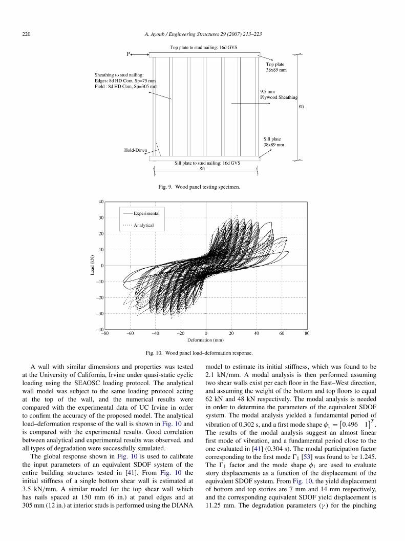
5. Validation of material model
The proposed pinched degrading material model is validatedthrough a correlation study with an experimentally testedwood shear wall. The wood shear wall is modeled using aSingle Degree of Freedom (SDOF) system with calibratedparameters. The selected specimen was tested at UC Irvineas a part of a general investigation on the seismic behaviorof wood shear walls [11]. The experimental versus analyticalcyclic load–deformation plot for the test specimen is shownin Fig. 8. The degradation parameters γ and c for all four
types of degradation were selected to be equal to 200, and 1respectively. The pinching parameters κ and αpinch were bothassumed to equal 0.5. These values were found to providethe better match with the experimental results. From Fig. 8,it is rather obvious that the eight-parameter pinched degradingmaterial model successfully described the global behavior, andthe decay in strength under large load reversals. It is worthmentioning that the loading protocol used for the selectedtest specimen followed the Sequential Phased Protocol, whichincludes several low-amplitude cycles that could lead to nailfatigue.
While the SDOF model is adequate for estimating the globalbehavior of wood shear walls, its use is limited by the factthat input parameters such as initial stiffness, yield force, anddegradation values are often unknown a priori. SDOF modelsare also practical for evaluating the global seismic demandsof wood building systems, as their typical behavior is first-mode dominant. However, in order to make effective use ofSDOF models, an initial analysis using the previously describedshear wall model needs to be performed in order to accurately
A. Ayoub / Engineering Structures 29 (2007) 213–223 219
Fig. 7. Cap degradation of pinching model.
Fig. 8. Behavior of UC Irvine wood specimen.
calibrate the input parameters needed for the SDOF model. Theprocess is described next.
6. Evaluation of global behavior of wood building struc-tures
In order to evaluate the global response of wood buildings,the proposed shear wall numerical model described earlier isused first to calibrate the parameters of an equivalent SDOFsystem. Consider the two-story wood building tested underthe shake table in [41]. The building total height includingthe thickness of slabs is 5.2 m (17 ft) and its width in theEast–West direction is 4.9 m (16 ft). A model for the shearwall of the bottom floor in the East–West direction is developedusing the proposed element added to the material library ofthe commercial software DIANA. Only half of the wall ismodeled, assuming symmetry. The dimension of the wall modelis 2.45 m by 2.45 m (8 ft by 8 ft) with studs spaced at 406 mm(16 in.) and nails at 75 mm (3 in.) at panel edges and at
305 mm (12 in.) at interior studs as shown in Fig. 9. The finiteelement model consists of an elastic shell element to model theplywood shear wall, elastic beam elements to model the studsand top and bottom plates, and distributed interface elementsto model the nails. The nail pullout behavior is assumed tobe elastic, while the nail shear in both directions is assumedto follow the newly developed degrading pinched hystereticbehavior. The pinched hysteretic behavior assumed for the nailshas a yield force equals 0.75 kN (0.17 k) and an elastic slopeequals 0.5 kN/mm (2.88 k/in.), while the elastic stiffness ofthe pullout behavior equals 0.3 kN/mm (1.73 k/in.). The nailmaterial properties are close to the ones obtained in [51] andlater used in [39] and [52]. The degradation parameters usedare the same as the ones used for the SDOF system. Young’smodulus for timber was assumed to equal 11 GPa, and thePoisson’s ratio to equal 0.3. The sill plate is assumed to be fixed,but an interface element between the shear wall and the sill plateis introduced to model uplift effects.
220 A. Ayoub / Engineering Structures 29 (2007) 213–223
Fig. 9. Wood panel testing specimen.
Fig. 10. Wood panel load–deformation response.
A wall with similar dimensions and properties was testedat the University of California, Irvine under quasi-static cyclicloading using the SEAOSC loading protocol. The analyticalwall model was subject to the same loading protocol actingat the top of the wall, and the numerical results werecompared with the experimental data of UC Irvine in orderto confirm the accuracy of the proposed model. The analyticalload–deformation response of the wall is shown in Fig. 10 andis compared with the experimental results. Good correlationbetween analytical and experimental results was observed, andall types of degradation were successfully simulated.
The global response shown in Fig. 10 is used to calibratethe input parameters of an equivalent SDOF system of theentire building structures tested in [41]. From Fig. 10 theinitial stiffness of a single bottom shear wall is estimated at3.5 kN/mm. A similar model for the top shear wall whichhas nails spaced at 150 mm (6 in.) at panel edges and at305 mm (12 in.) at interior studs is performed using the DIANA
model to estimate its initial stiffness, which was found to be2.1 kN/mm. A modal analysis is then performed assumingtwo shear walls exist per each floor in the East–West direction,and assuming the weight of the bottom and top floors to equal62 kN and 48 kN respectively. The modal analysis is neededin order to determine the parameters of the equivalent SDOFsystem. The modal analysis yielded a fundamental period ofvibration of 0.302 s, and a first mode shape φ1 =
[0.496 1
]T .The results of the modal analysis suggest an almost linearfirst mode of vibration, and a fundamental period close to theone evaluated in [41] (0.304 s). The modal participation factorcorresponding to the first mode 01 [53] was found to be 1.245.The 01 factor and the mode shape φ1 are used to evaluatestory displacements as a function of the displacement of theequivalent SDOF system. From Fig. 10, the yield displacementof bottom and top stories are 7 mm and 14 mm respectively,and the corresponding equivalent SDOF yield displacement is11.25 mm. The degradation parameters (γ ) for the pinching
A. Ayoub / Engineering Structures 29 (2007) 213–223 221
Table 1Comparison of predicted response of wood building structure
Test data Team A Team B Team C Team D Team E Current study
Maximum roof disp. (mm) 69.7 54.3 58.0 19.3 39.0 39.2 70.7% error −22.1 −16.78 −72.3 −44.0 −43.7 +1.43
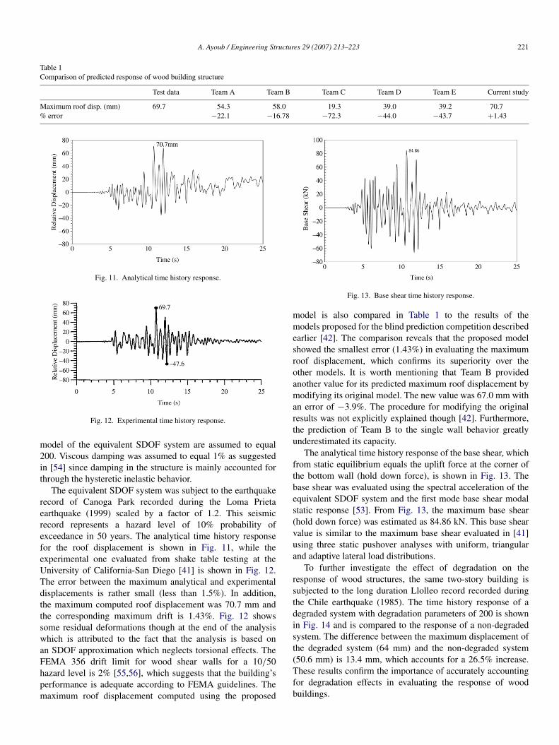
Fig. 11. Analytical time history response.
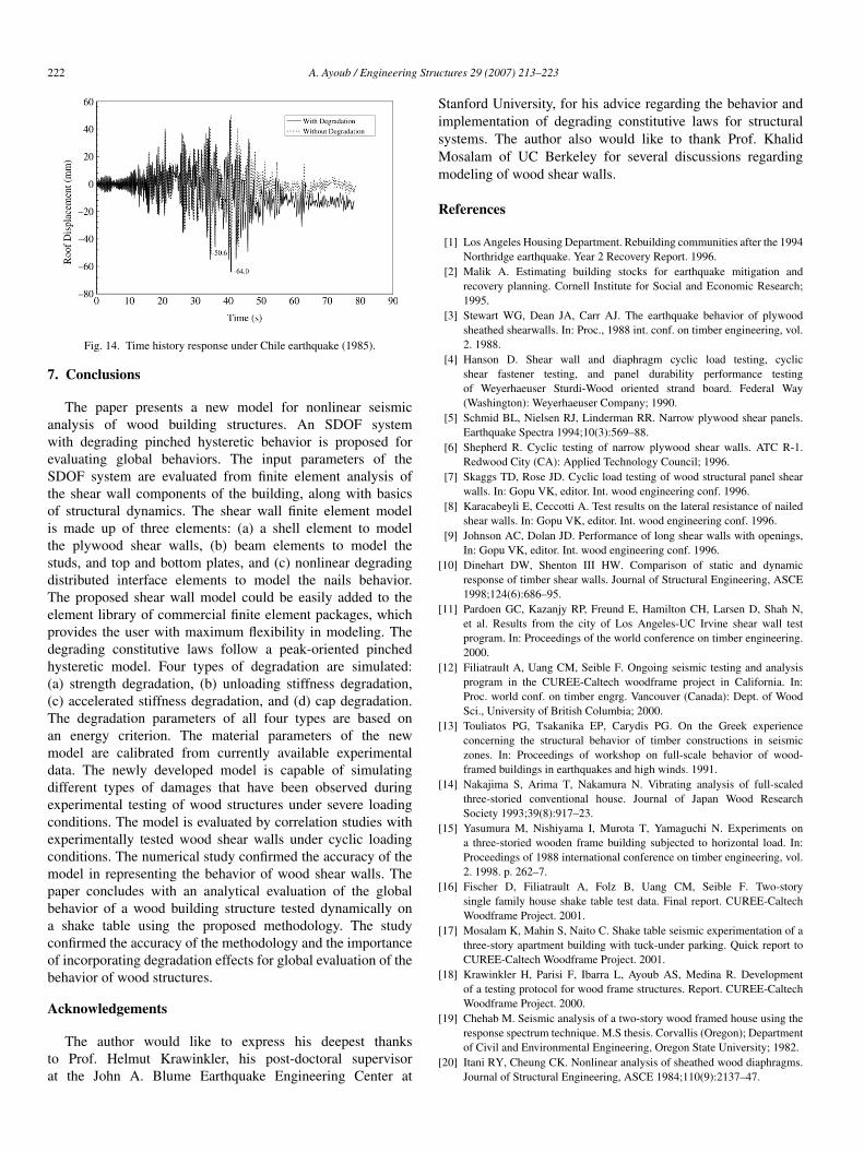
Fig. 12. Experimental time history response.
model of the equivalent SDOF system are assumed to equal200. Viscous damping was assumed to equal 1% as suggestedin [54] since damping in the structure is mainly accounted forthrough the hysteretic inelastic behavior.
The equivalent SDOF system was subject to the earthquakerecord of Canoga Park recorded during the Loma Prietaearthquake (1999) scaled by a factor of 1.2. This seismicrecord represents a hazard level of 10% probability ofexceedance in 50 years. The analytical time history responsefor the roof displacement is shown in Fig. 11, while theexperimental one evaluated from shake table testing at theUniversity of California-San Diego [41] is shown in Fig. 12.The error between the maximum analytical and experimentaldisplacements is rather small (less than 1.5%). In addition,the maximum computed roof displacement was 70.7 mm andthe corresponding maximum drift is 1.43%. Fig. 12 showssome residual deformations though at the end of the analysiswhich is attributed to the fact that the analysis is based onan SDOF approximation which neglects torsional effects. TheFEMA 356 drift limit for wood shear walls for a 10/50hazard level is 2% [55,56], which suggests that the building’sperformance is adequate according to FEMA guidelines. Themaximum roof displacement computed using the proposed
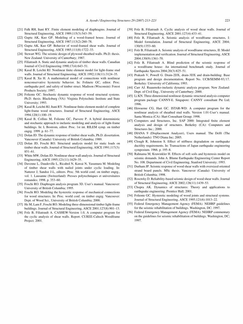
Fig. 13. Base shear time history response.
model is also compared in Table 1 to the results of themodels proposed for the blind prediction competition describedearlier [42]. The comparison reveals that the proposed modelshowed the smallest error (1.43%) in evaluating the maximumroof displacement, which confirms its superiority over theother models. It is worth mentioning that Team B providedanother value for its predicted maximum roof displacement bymodifying its original model. The new value was 67.0 mm withan error of −3.9%. The procedure for modifying the originalresults was not explicitly explained though [42]. Furthermore,the prediction of Team B to the single wall behavior greatlyunderestimated its capacity.
The analytical time history response of the base shear, whichfrom static equilibrium equals the uplift force at the corner ofthe bottom wall (hold down force), is shown in Fig. 13. Thebase shear was evaluated using the spectral acceleration of theequivalent SDOF system and the first mode base shear modalstatic response [53]. From Fig. 13, the maximum base shear(hold down force) was estimated as 84.86 kN. This base shearvalue is similar to the maximum base shear evaluated in [41]using three static pushover analyses with uniform, triangularand adaptive lateral load distributions.
To further investigate the effect of degradation on theresponse of wood structures, the same two-story building issubjected to the long duration Llolleo record recorded duringthe Chile earthquake (1985). The time history response of adegraded system with degradation parameters of 200 is shownin Fig. 14 and is compared to the response of a non-degradedsystem. The difference between the maximum displacement ofthe degraded system (64 mm) and the non-degraded system(50.6 mm) is 13.4 mm, which accounts for a 26.5% increase.These results confirm the importance of accurately accountingfor degradation effects in evaluating the response of woodbuildings.
222 A. Ayoub / Engineering Structures 29 (2007) 213–223
Fig. 14. Time history response under Chile earthquake (1985).
7. Conclusions
The paper presents a new model for nonlinear seismicanalysis of wood building structures. An SDOF systemwith degrading pinched hysteretic behavior is proposed forevaluating global behaviors. The input parameters of theSDOF system are evaluated from finite element analysis ofthe shear wall components of the building, along with basicsof structural dynamics. The shear wall finite element modelis made up of three elements: (a) a shell element to modelthe plywood shear walls, (b) beam elements to model thestuds, and top and bottom plates, and (c) nonlinear degradingdistributed interface elements to model the nails behavior.The proposed shear wall model could be easily added to theelement library of commercial finite element packages, whichprovides the user with maximum flexibility in modeling. Thedegrading constitutive laws follow a peak-oriented pinchedhysteretic model. Four types of degradation are simulated:(a) strength degradation, (b) unloading stiffness degradation,(c) accelerated stiffness degradation, and (d) cap degradation.The degradation parameters of all four types are based onan energy criterion. The material parameters of the newmodel are calibrated from currently available experimentaldata. The newly developed model is capable of simulatingdifferent types of damages that have been observed duringexperimental testing of wood structures under severe loadingconditions. The model is evaluated by correlation studies withexperimentally tested wood shear walls under cyclic loadingconditions. The numerical study confirmed the accuracy of themodel in representing the behavior of wood shear walls. Thepaper concludes with an analytical evaluation of the globalbehavior of a wood building structure tested dynamically ona shake table using the proposed methodology. The studyconfirmed the accuracy of the methodology and the importanceof incorporating degradation effects for global evaluation of thebehavior of wood structures.
Acknowledgements
The author would like to express his deepest thanksto Prof. Helmut Krawinkler, his post-doctoral supervisorat the John A. Blume Earthquake Engineering Center at
Stanford University, for his advice regarding the behavior andimplementation of degrading constitutive laws for structuralsystems. The author also would like to thank Prof. KhalidMosalam of UC Berkeley for several discussions regardingmodeling of wood shear walls.
References
[1] Los Angeles Housing Department. Rebuilding communities after the 1994Northridge earthquake. Year 2 Recovery Report. 1996.
[2] Malik A. Estimating building stocks for earthquake mitigation andrecovery planning. Cornell Institute for Social and Economic Research;1995.
[3] Stewart WG, Dean JA, Carr AJ. The earthquake behavior of plywoodsheathed shearwalls. In: Proc., 1988 int. conf. on timber engineering, vol.2. 1988.
[4] Hanson D. Shear wall and diaphragm cyclic load testing, cyclicshear fastener testing, and panel durability performance testingof Weyerhaeuser Sturdi-Wood oriented strand board. Federal Way(Washington): Weyerhaeuser Company; 1990.
[5] Schmid BL, Nielsen RJ, Linderman RR. Narrow plywood shear panels.Earthquake Spectra 1994;10(3):569–88.
[6] Shepherd R. Cyclic testing of narrow plywood shear walls. ATC R-1.Redwood City (CA): Applied Technology Council; 1996.
[7] Skaggs TD, Rose JD. Cyclic load testing of wood structural panel shearwalls. In: Gopu VK, editor. Int. wood engineering conf. 1996.
[8] Karacabeyli E, Ceccotti A. Test results on the lateral resistance of nailedshear walls. In: Gopu VK, editor. Int. wood engineering conf. 1996.
[9] Johnson AC, Dolan JD. Performance of long shear walls with openings,In: Gopu VK, editor. Int. wood engineering conf. 1996.
[10] Dinehart DW, Shenton III HW. Comparison of static and dynamicresponse of timber shear walls. Journal of Structural Engineering, ASCE1998;124(6):686–95.
[11] Pardoen GC, Kazanjy RP, Freund E, Hamilton CH, Larsen D, Shah N,et al. Results from the city of Los Angeles-UC Irvine shear wall testprogram. In: Proceedings of the world conference on timber engineering.2000.
[12] Filiatrault A, Uang CM, Seible F. Ongoing seismic testing and analysisprogram in the CUREE-Caltech woodframe project in California. In:Proc. world conf. on timber engrg. Vancouver (Canada): Dept. of WoodSci., University of British Columbia; 2000.
[13] Touliatos PG, Tsakanika EP, Carydis PG. On the Greek experienceconcerning the structural behavior of timber constructions in seismiczones. In: Proceedings of workshop on full-scale behavior of wood-framed buildings in earthquakes and high winds. 1991.
[14] Nakajima S, Arima T, Nakamura N. Vibrating analysis of full-scaledthree-storied conventional house. Journal of Japan Wood ResearchSociety 1993;39(8):917–23.
[15] Yasumura M, Nishiyama I, Murota T, Yamaguchi N. Experiments ona three-storied wooden frame building subjected to horizontal load. In:Proceedings of 1988 international conference on timber engineering, vol.2. 1998. p. 262–7.
[16] Fischer D, Filiatrault A, Folz B, Uang CM, Seible F. Two-storysingle family house shake table test data. Final report. CUREE-CaltechWoodframe Project. 2001.
[17] Mosalam K, Mahin S, Naito C. Shake table seismic experimentation of athree-story apartment building with tuck-under parking. Quick report toCUREE-Caltech Woodframe Project. 2001.
[18] Krawinkler H, Parisi F, Ibarra L, Ayoub AS, Medina R. Developmentof a testing protocol for wood frame structures. Report. CUREE-CaltechWoodframe Project. 2000.
[19] Chehab M. Seismic analysis of a two-story wood framed house using theresponse spectrum technique. M.S thesis. Corvallis (Oregon); Departmentof Civil and Environmental Engineering, Oregon State University; 1982.
[20] Itani RY, Cheung CK. Nonlinear analysis of sheathed wood diaphragms.Journal of Structural Engineering, ASCE 1984;110(9):2137–47.
A. Ayoub / Engineering Structures 29 (2007) 213–223 223
[21] Falk RH, Itani RY. Finite element modeling of diaphragms. Journal ofStructural Engineering, ASCE 1989;115(3):543–59.
[22] Gupta AK, Kuo GP. Modeling of a wood-framed house. Journal ofStructural Engineering, ASCE 1987;113(2):260–78.
[23] Gupta AK, Kuo GP. Behavior of wood-framed shear walls. Journal ofStructural Engineering, ASCE 1985;111(8):1722–33.
[24] Stewart WG. The seismic design of plywood sheathed walls. Ph.D. thesis.New Zealand: University of Canterbury; 1987.
[25] Filiatrault A. Static and dynamic analysis of timber shear walls. CanadianJournal of Civil Engineering 1990;17(4):643–51.
[26] Kasal B, Leichti RJ. Nonlinear finite element model for light-frame studwalls. Journal of Structural Engineering, ASCE 1992;118(11):3124–35.
[27] Kasal B, Xu H. A mathematical model of connections with nonlinearnonconservative hysteretic behavior. In: Folinete GC, editor. Proc.earthquake perf. and safety of timber struct. Madison (Wisconsin): ForestProducts Society; 1997.
[28] Foliente GC. Stochastic dynamic response of wood structural systems.Ph.D. thesis. Blacksburg (VA): Virginia Polytechnic Institute and StateUniversity; 1993.
[29] Kasal B, Leichti RJ, Itani RY. Nonlinear finite element model of completelight-frame wood structures. Journal of Structural Engineering, ASCE1994;120(1):100–19.
[30] Kasal B, Collins M, Foliente GC, Paevere P. A hybrid deterministicand stochastic approach to inelastic modeling and analysis of light-framebuildings. In: L Bostrom, editor. Proc. 1st int. RILEM symp. on timberengrg. 1999. p. 61–77.
[31] Dolan JD. The dynamic response of timber shear walls, Ph.D. dissertation.Vancouver (Canada): University of British Columbia; 1989.
[32] Dolan JD, Foschi RO. Structural analysis model for static loads ontimber shear walls. Journal of Structural Engineering, ASCE 1991;117(3):851–61.
[33] White MW, Dolan JD. Nonlinear shear wall analysis. Journal of StructuralEngineering, ASCE 1995;121(11):1629–35.
[34] Davenne L, Daudeville L, Ricahrd N, Kawai N, Yasumura M. Modelingof timber shear walls with nailed joints under cyclic loading. In:Natterer J, Sandoz J-L, editors. Proc. 5th world conf. on timber engrg.,vol. 1. Lausanne (Switzerland): Presses polytechniques et universitairesromandes; 1998. p. 353–60.
[35] Foschi RO. Diaphragm analysis program 3D. User’s manual. Vancouver:University of British Columbia; 1995.
[36] Foschi RO. Modeling the hysteretic response of mechanical connectionsfor wood structures. In: Proc. world conf. on timber engrg. Vancouver:Dept. of Wood Sci., University of British Columbia; 2000.
[37] He M, Lam F, Foschi RO. Modeling three-dimensional timber light-framebuildings. Journal of Structural Engineering, ASCE 2001;127(8):901–13.
[38] Folz B, Filiatrault A. CASHEW-Version 1.0, A computer program forthe cyclic analysis of shear walls. Report. CUREE-Caltech WoodframeProject. 2001.
[39] Folz B, Filiatrault A. Cyclic analysis of wood shear walls. Journal ofStructural Engineering, ASCE 2001;127(4):433–41.
[40] Folz B, Filiatrault A. Seismic analysis of woodframe structures, I:Model formulation. Journal of Structural Engineering, ASCE 2004;130(9):1353–60.
[41] Folz B, Filiatrault A. Seismic analysis of woodframe structures, II: Modelimplementation and verification. Journal of Structural Engineering, ASCE2004;130(9):1361–70.
[42] Folz B, Filiatrault A. Blind prediction of the seismic response ofa woodframe house: An international benchmark study. Journal ofEarthquake Spectra 2004;20(3):825–51.
[43] Prakash V, Powell G. Drain-2DX, drain-3DX and drain-building: Baseprogram and design documentation. Report No. UCB/SEMM-93/17.Berkeley: University of California; 1993.
[44] Carr AJ. Ruaumoko-inelastic dynamic analysis program. New Zealand:Dept. of Civil Eng., University of Canterbury; 2000.
[45] Li KN. Three dimensional nonlinear dynamic structural analysis computerprogram package CANNY-E. Singapore: CANNY consultant Pte Ltd;1996.
[46] Ekwueme CG, Hart GC. ISTAR-WD: A computer program for thenonlinear analysis of sheathed stud walls. Version 1.01-User’s manual.Santa Monica (CA): Hart Consultant Group; 1998.
[47] Computers and Structures, Inc. SAP 2000: Integrated finite elementanalysis and design of structures. Berkeley (CA): Computers andStructures Inc.; 2000.
[48] DIANA 9 (Displacement Analyzer), Users manual. The Delft (TheNetherlands): TNO Diana Inc; 2005.
[49] Clough R, Johnston S. Effect of stiffness degradation on earthquakeductility requirements. In: Transactions of Japan earthquake engineeringsymposium. 1966. p. 195–8.
[50] Rahnama M, Krawinkler H. Effects of soft soils and hysteresis model onseismic demands. John A. Blume Earthquake Engineering Center ReportNo. 108. Department of Civil Engineering, Stanford University; 1993.
[51] Durham JP. Seismic response of wood shear walls with oversized orientedstrand board panels. MSc thesis. Vancouver (Canada): University ofBritish Columbia; 1998.
[52] Rosowky D. Reliability-based seismic design of wood shear walls. Journalof Structural Engineering, ASCE 2002;128(11):1439–53.
[53] Chopra AK. Dynamics of structures: Theory and applications toearthquake engineering. Prentice Hall; 2001.
[54] Foliente GC. Hysteretic modeling of wood joints and structural systems.Journal of Structural Engineering, ASCE 1995;121(6):1013–22.
[55] Federal Emergency Management Agency (FEMA). NEHRP guidelinesfor the seismic rehabilitation of buildings. Washington, DC; 1997.
[56] Federal Emergency Management Agency (FEMA). NEHRP commentaryon the guidelines for seismic rehabilitation of buildings. Washington, DC;1997.