Embed Size (px)
Citation preview

ISSN: 2277-9655
[Mathur* et al., 6(1): January, 2017] Impact Factor: 4.116
IC™ Value: 3.00 CODEN: IJESS7
http: // www.ijesrt.com © International Journal of Engineering Sciences & Research Technology
[356]
IJESRT INTERNATIONAL JOURNAL OF ENGINEERING SCIENCES & RESEARCH
TECHNOLOGY
SEISMIC ANALYSIS OF STRUCTURE ON SLOPING GROUND USING CLAY
AND CEMENT INFILL Samarth Joshi*, Dr. Raman Nateriya, Dr. Priyanka Dhurvey, Prafulla Kumar Tiwari
* Manit Bhopal M.P. India
DOI: 10.5281/zenodo.259587
ABSTRACT RC frames with masonry infill walls are a common practice in countries like India, where the region is prone to
seismic activity. Generally the masonry infill walls are treated as nonstructural part in structural study and role of
its mass is well-thought-out and it’s structural feature like strength and rigidity is not measured. The structures in
from top to bottom seismic areas are mostly vulnerable to plain damages. Apart from the gravity load structure
has to endure to lateral load which also develop high stresses. Now day’s reinforced concrete frames are used in
building structure practice around the globe. The vertical gap in reinforced concrete frames i.e. formed by the
columns and beams are commonly filled in by brick or masonry and it is discussed as brick infill wall or panels.
Now the construction of frame is done, these walls are built of brunt clay bricks in cement mortar.It are well
known to us that masonry infills, though non-engineered and term as non-structural, may provide maximum of
the earthquake resistance and prevent collapse of weak RC structures. The aim of this study is to concentrate the
impact of brick work infills on reinforced concrete frames subjected to seismic force mainly in zone II and zone
V. For this purpose an equivalent discrete shear-type model with seven storeys is taken and two cases were taken
into account i.e. with and without infills. The adopted mathematical model was proved by comparing numerical
and test results. They show of a maximum number of different reinforced concrete three bay-frames, bare and
infilled, subjected to ten ground motion was study. The wide ranges of behavior are taken into account want to
create response spectra for numerous significant parameters characterizing the nature of bare and infilled frames.
Moreover, infills, if shows in all storeys, provide a important contribution to the energy dissipation capacity,
decreasing the dissipation energy demands in frame elements and decreasing significantly the maximum
displacements. It shows the influence of masonry is of great importance, even though strongly depending on the
feature of the ground motion, especially for non-seismic frames, which have a lower capacity of dissipating energy
than the seismic ones.
KEYWORDS: seismic zone, infills, staad.pro, deflection, axial force, sloping ground
INTRODUCTION The observation of the response of building structures engineered or not engineered to resist major or moderate
earthquakes, after the past earthquakes highlighted the significant influence of the infills in the feature of their
seismic nature. Infills were commonly classified as non structural elements, and their impact was deserted during
the modeling phase of the structure leading to substantial inaccuracy in predicting the actual seismic result of
framed structures. The infilled frames presents a wide variability due to the characteristics of the ground motion,
the mechanical properties of infills, the overall geometry, the frame-to-infill interface behavior, the horizontal or
vertical arrangement of the infills, the presence of openings and their dimension and location, etc. Moreover, the
problem of the out-of-plane nature of infilled frames indicate an suitable attention not only because its potentially
hazardous effect, but also in terms of its dealings with in-plane response. The impact on the infills for the seismic
nature of buildings may be positive or negative, depending on a large number of influential parameters. Generally,
the performance of the structure can be expressively increase by the improvement of strength and dissipation
capacity due to the masonry infills, even if in presence of an increasing in earthquake inertia forces. However, it
is necessary to understand the nature of repeated horizontal loading for a proper design of masonry infilled
reinforced concrete member. Neglecting the significant interaction between the filler walls and building frames is
the main reason why structural systems incorporating integrated infills panels react to strong earthquakes in a
manner quite different from the expected one. Another significant issue is related to the numerical simulation of

ISSN: 2277-9655
[Mathur* et al., 6(1): January, 2017] Impact Factor: 4.116
IC™ Value: 3.00 CODEN: IJESS7
http: // www.ijesrt.com © International Journal of Engineering Sciences & Research Technology
[357]
infilled frames. The different techniques for idealizing this structural model can be divided into two local or micro-
models and simplified macromodels. The first group involves the models, in which the structure is divided into
numerous elements to take into account of the local effect in detail, whereas the second group includes simplified
models based on a physical understanding of the nature of the infill panel. In these work three cases were studied
The observation of the response of building structures, engineered or not engineered to resist major or moderate
earthquakes, after the past earthquakes highlighted the significant contribution of the infills in the characterization
of their seismic behavior Infills were typically delegated non basic components, and their impact was neglected
during the modeling phase of the structure leading to considerable error in determining the actual response of
earthquake of the enclosed structures. The infilled frames presents a wide variability due to the characteristics of
the ground motion, the mechanical properties of infills, the overall geometry, the frame-to-infill interface
behavior, the horizontal or vertical arrangement of the infills, the presence of openings and their dimension and
location, etc. Moreover, the problem of the out-of-plane behavior of infilled frames deserves appropriate attention
not only because its potentially dangerous effect, but also in terms of its interaction with in-plane response. The
impact of the infills on the seismic behavior of buildings may be positive or negative, depending on a large number
of influential parameters. Generally, the performance of the structure can be significantly improved by the increase
of strength and dissipation capacity due to the masonry infills, even if in presence of an increasing in earthquake
inertia forces. However, for a proper design of masonry infilled reinforced concrete frames it is necessary to
completely understand their behavior under repeated horizontal loading. Neglecting the significant interaction
between the filler walls and building frames is the main reason why structural systems incorporating integrated
infills panels react to strong earthquakes in a manner quite different from the expected one. Another important
issue is related to the numerical simulation of infilled frames. The different techniques for idealizing this structural
model can be divided into two local or micro-models and simplified macromodels. The primary group includes
the models, in which the structure is separated into various components to assess the nearby impact in detail,
though the second group incorporates simplified models in view of a physical comprehension of the behavior of
the infill panel. In these work three cases were studied
1. Seismic analysis of structure on sloping ground without infill
2. Seismic analysis of structure on sloping ground with clay brick infill
3. Seismic analysis of structure on sloping ground with cement brick infill.
Masonry walls are given essentially to the reason for apportioning and covering however they confer significant
strength and stiffness to the building outline for opposing loads. The strength and stiffness contribution of infill
brick work is generally not taken into account during designing. Because of the vulnerability in the quality
properties of stone work, separation of infill from frame, low rigidity, brittle characteristics of masonry walls, less
out of plane quality and rigidity and so on. Reinforced brick masonry as infill in RC frames provide better contact
at the interface. Their out of plane quality and firmness is likewise higher. In this study an attempt has been made
to carry out dynamic simulation of multistoried reinforced rat trap clay brick masonry infilled RC frames by finite
element analysis.
METHODOLOGY This work deals with comparative study of seismic activities on G+7 unsymetrical frame with different soil
types and sloping ground. The followings steps has been taken:
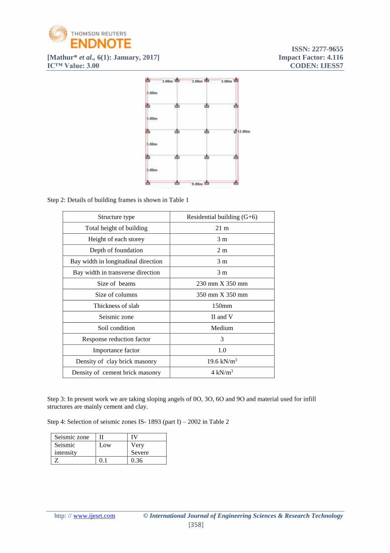
Step 1: Selection of geometry of building frames.
ISSN: 2277-9655
[Mathur* et al., 6(1): January, 2017] Impact Factor: 4.116
IC™ Value: 3.00 CODEN: IJESS7
http: // www.ijesrt.com © International Journal of Engineering Sciences & Research Technology
[358]
Step 2: Details of building frames is shown in Table 1
Structure type Residential building (G+6)
Total height of building 21 m
Height of each storey 3 m
Depth of foundation 2 m
Bay width in longitudinal direction 3 m
Bay width in transverse direction 3 m
Size of beams 230 mm X 350 mm
Size of columns 350 mm X 350 mm
Thickness of slab 150mm
Seismic zone II and V
Soil condition Medium
Response reduction factor 3
Importance factor 1.0
Density of clay brick masonry 19.6 kN/m3
Density of cement brick masonry 4 kN/m3
Step 3: In present work we are taking sloping angels of 0O, 3O, 6O and 9O and material used for infill
structures are mainly cement and clay.
Step 4: Selection of seismic zones IS- 1893 (part I) – 2002 in Table 2
Seismic zone II IV
Seismic
intensity
Low Very
Severe
Z 0.1 0.36
ISSN: 2277-9655
[Mathur* et al., 6(1): January, 2017] Impact Factor: 4.116
IC™ Value: 3.00 CODEN: IJESS7
http: // www.ijesrt.com © International Journal of Engineering Sciences & Research Technology
[359]
Step 5: Formation of load combination
Load case no. Load case details
1. E.Q. IN X DIR.
2. E.Q. IN Z DIR.
3. DEAD LOAD
4. LIVE LOAD
5. 1.5 (DEAD + LIVE)
6. 1.5 (DL + EL_X)
7. 1.5 (DL - EL_X)
8. 1.5 (DL + EL_Z)
9. 1.5 (DL - EL_Z)
10. 1.2 (DL + LL + EL_X)
11. 1.2 (DL + LL - EL_X)
12. 1.2 (DL + LL + EL_Z)
13. 1.2 (DL + LL - EL_Z)
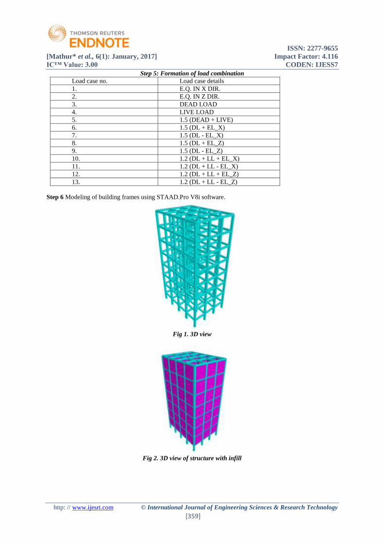
Step 6 Modeling of building frames using STAAD.Pro V8i software.
Fig 1. 3D view
Fig 2. 3D view of structure with infill
ISSN: 2277-9655
[Mathur* et al., 6(1): January, 2017] Impact Factor: 4.116
IC™ Value: 3.00 CODEN: IJESS7
http: // www.ijesrt.com © International Journal of Engineering Sciences & Research Technology
[360]
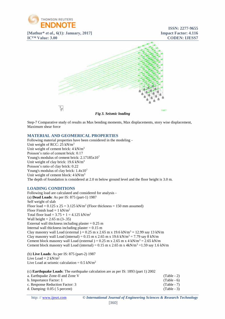
Fig 3. Seismic loading
Step-7 Comparative study of results as Max bending moments, Max displacements, story wise displacement,
Maximum shear force
MATERIAL AND GEOMERICAL PROPERTIES Following material properties have been considered in the modeling -
Unit weight of RCC: 25 kN/m3
Unit weight of cement brick: 4 kN/m3
Poisson’s ratio of cement brick: 0.17
Young's modulus of cement brick: 2.17185x10⁷
Unit weight of clay brick: 19.6 kN/m3
Poisson’s ratio of clay brick: 0.22
Young's modulus of clay brick: 1.4x10⁷
Unit weight of cement block: 4 kN/m3
The depth of foundation is considered at 2.0 m below ground level and the floor height is 3.0 m.
LOADING CONDITIONS Following load are calculated and considered for analysis -
(a) Dead Loads: As per IS: 875 (part-1) 1987
Self weight of slab
Floor load = 0.125 x 25 = 3.125 kN/m2 (Floor thickness = 150 mm assumed)
Floor Finish load = 1 kN/m2
Total floor load = 3.75 + 1 = 4.125 kN/m2
Wall height = 2.65 m (3-.35)
External wall thickness including plaster = 0.25 m
Internal wall thickness including plaster = 0.15 m
Clay masonry wall Load (external ) = 0.25 m x 2.65 m x 19.6 kN/m3 = 12.99 say 13 kN/m
Clay masonry wall Load (internal) = 0.15 m x 2.65 m x 19.6 kN/m3 = 7.79 say 8 kN/m
Cement block masonry wall Load (external ) = 0.25 m x 2.65 m x 4 kN/m3 = 2.65 kN/m
Cement block masonry wall Load (internal) = 0.15 m x 2.65 m x 4kN/m3 =1.59 say 1.6 kN/m
(b) Live Loads: As per IS: 875 (part-2) 1987
Live Load = 2 kN/m2
Live Load at seismic calculation = 0.5 kN/m2
(c) Earthquake Loads: The earthquake calculation are as per IS: 1893 (part 1) 2002
a. Earthquake Zone-II and Zone V (Table - 2)
b. Importance Factor: 1 (Table - 6)
c. Response Reduction Factor: 3 (Table - 7)
d. Damping: 0.05 ( 5 percent) (Table - 3)
ISSN: 2277-9655
[Mathur* et al., 6(1): January, 2017] Impact Factor: 4.116
IC™ Value: 3.00 CODEN: IJESS7
http: // www.ijesrt.com © International Journal of Engineering Sciences & Research Technology
[361]
e. Soil Type: Medium Soil (Assumed)
f. Period in X direction (PX):0.09∗ℎ
√𝑑𝑥seconds Clause 7.6.2
Period in X direction (PX) = 0.09x21/sq. root 9 = 0.63
g. Period in Z direction (Pz):0.09∗ℎ
√𝑑𝑧seconds Clause 7.6.2 [21]
Period in X direction (Pz) = 0.09x21/12 = 0.546
Where, h = height of the building
dx= length of building in x direction
And dz= length of building in z direction
AhX = (Z/2 x I/R x Sa/g)
DESCRIPTION OF THE STRUCTURAL MODEL Geometry
For the study 07 storey building are considered. The building has regular and irregular shape and a storey height
of 3 m each in all the floors and depth of foundation taken as 2 m. The column is kept square.
Modeling
The building is considered to be located in seismic zone II and zone V intended for residential use. Response
reduction factor for the ordinary moment resisting frame has taken as 3.0. The finishing load on the floors is taken
to be 1.0 kN/m2. The live load on floor is taken as 2.0 kN/m2. In seismic weight calculations, 25 % of the floor
live loads are considered in the analysis.
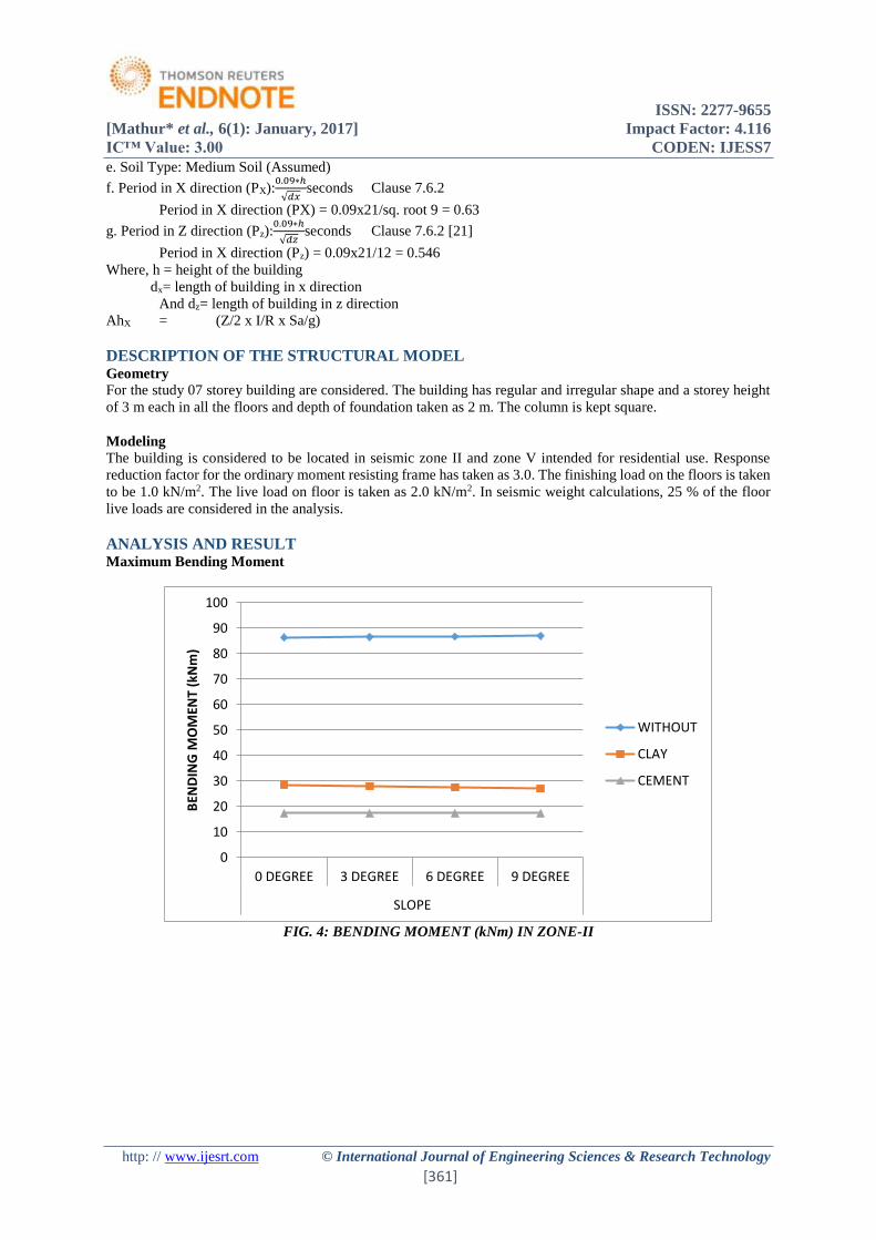
ANALYSIS AND RESULT Maximum Bending Moment
FIG. 4: BENDING MOMENT (kNm) IN ZONE-II
0
10
20
30
40
50
60
70
80
90
100
0 DEGREE 3 DEGREE 6 DEGREE 9 DEGREE
SLOPE
BEN
DIN
G M
OM
ENT
(kN
m)
WITHOUT
CLAY
CEMENT
ISSN: 2277-9655
[Mathur* et al., 6(1): January, 2017] Impact Factor: 4.116
IC™ Value: 3.00 CODEN: IJESS7
http: // www.ijesrt.com © International Journal of Engineering Sciences & Research Technology
[362]
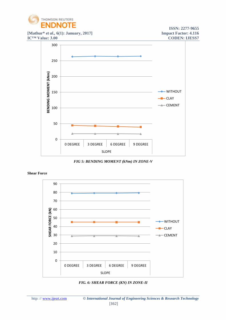
FIG 5: BENDING MOMENT (kNm) IN ZONE-V
Shear Force
FIG. 6: SHEAR FORCE (KN) IN ZONE-II
0
50
100
150
200
250
300
0 DEGREE 3 DEGREE 6 DEGREE 9 DEGREE
SLOPE
BEN
DIN
G M
OM
ENT
(kN
m)
WITHOUT
CLAY
CEMENT
0
10
20
30
40
50
60
70
80
90
0 DEGREE 3 DEGREE 6 DEGREE 9 DEGREE
SLOPE
SHEA
R F
OR
CE
(kN
)
WITHOUT
CLAY
CEMENT
ISSN: 2277-9655
[Mathur* et al., 6(1): January, 2017] Impact Factor: 4.116
IC™ Value: 3.00 CODEN: IJESS7
http: // www.ijesrt.com © International Journal of Engineering Sciences & Research Technology
[363]
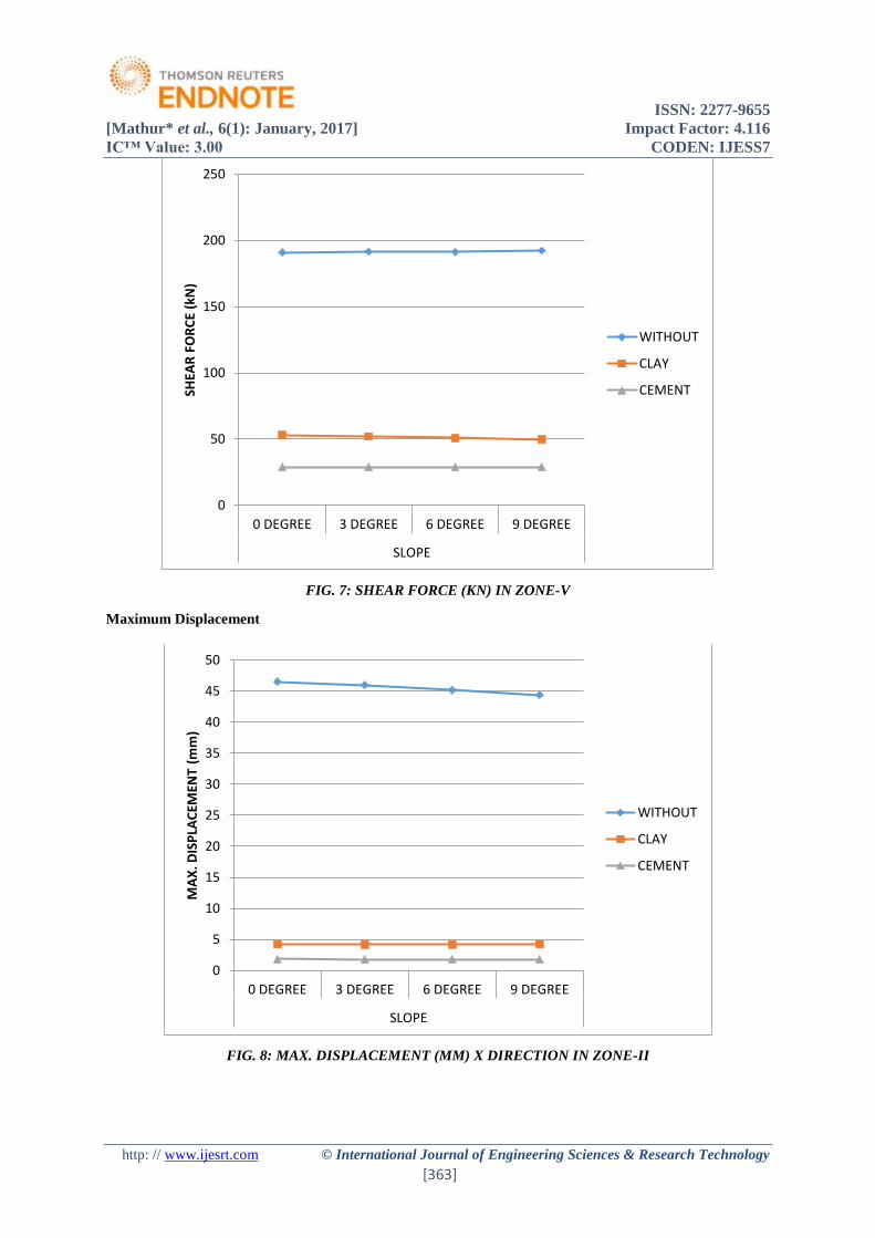
FIG. 7: SHEAR FORCE (KN) IN ZONE-V
Maximum Displacement
FIG. 8: MAX. DISPLACEMENT (MM) X DIRECTION IN ZONE-II
0
50
100
150
200
250
0 DEGREE 3 DEGREE 6 DEGREE 9 DEGREE
SLOPE
SHEA
R F
OR
CE
(kN
)
WITHOUT
CLAY
CEMENT
0
5
10
15
20
25
30
35
40
45
50
0 DEGREE 3 DEGREE 6 DEGREE 9 DEGREE
SLOPE
MA
X. D
ISP
LAC
EMEN
T (m
m)
WITHOUT
CLAY
CEMENT
ISSN: 2277-9655
[Mathur* et al., 6(1): January, 2017] Impact Factor: 4.116
IC™ Value: 3.00 CODEN: IJESS7
http: // www.ijesrt.com © International Journal of Engineering Sciences & Research Technology
[364]
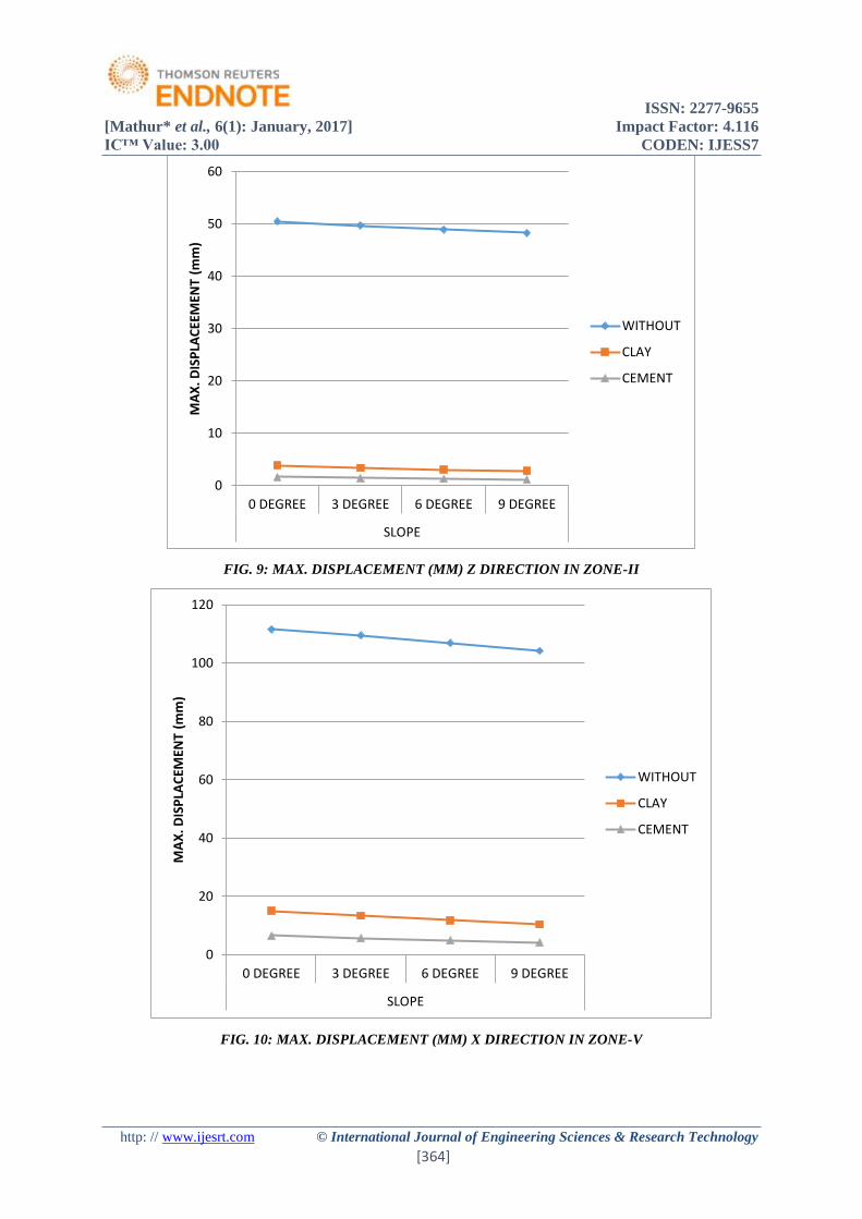
FIG. 9: MAX. DISPLACEMENT (MM) Z DIRECTION IN ZONE-II
FIG. 10: MAX. DISPLACEMENT (MM) X DIRECTION IN ZONE-V
0
10
20
30
40
50
60
0 DEGREE 3 DEGREE 6 DEGREE 9 DEGREE
SLOPE
MA
X. D
ISP
LAC
EEM
ENT
(mm
)
WITHOUT
CLAY
CEMENT
0
20
40
60
80
100
120
0 DEGREE 3 DEGREE 6 DEGREE 9 DEGREE
SLOPE
MA
X. D
ISP
LAC
EMEN
T (m
m)
WITHOUT
CLAY
CEMENT
ISSN: 2277-9655
[Mathur* et al., 6(1): January, 2017] Impact Factor: 4.116
IC™ Value: 3.00 CODEN: IJESS7
http: // www.ijesrt.com © International Journal of Engineering Sciences & Research Technology
[365]
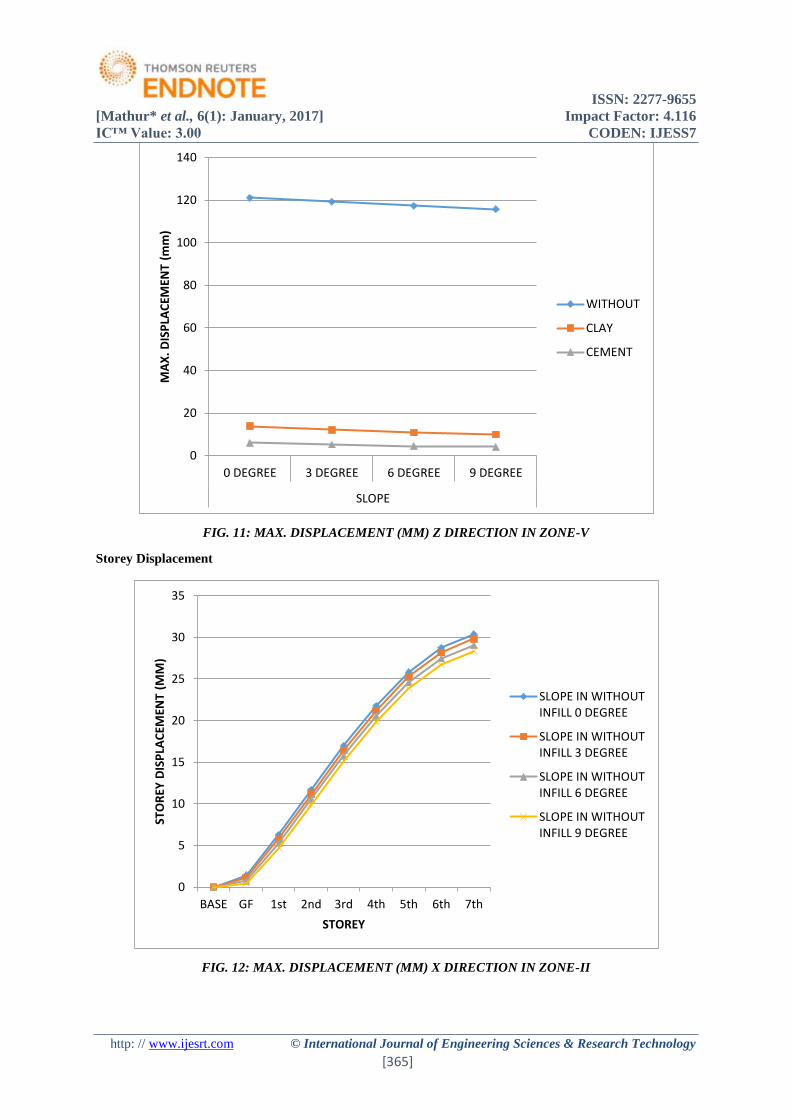
FIG. 11: MAX. DISPLACEMENT (MM) Z DIRECTION IN ZONE-V
Storey Displacement
FIG. 12: MAX. DISPLACEMENT (MM) X DIRECTION IN ZONE-II
0
20
40
60
80
100
120
140
0 DEGREE 3 DEGREE 6 DEGREE 9 DEGREE
SLOPE
MA
X. D
ISP
LAC
EMEN
T (m
m)
WITHOUT
CLAY
CEMENT
0
5
10
15
20
25
30
35
BASE GF 1st 2nd 3rd 4th 5th 6th 7th
STO
REY
DIS
PLA
CEM
ENT
(MM
)
STOREY
SLOPE IN WITHOUTINFILL 0 DEGREE
SLOPE IN WITHOUTINFILL 3 DEGREE
SLOPE IN WITHOUTINFILL 6 DEGREE
SLOPE IN WITHOUTINFILL 9 DEGREE
ISSN: 2277-9655
[Mathur* et al., 6(1): January, 2017] Impact Factor: 4.116
IC™ Value: 3.00 CODEN: IJESS7
http: // www.ijesrt.com © International Journal of Engineering Sciences & Research Technology
[366]
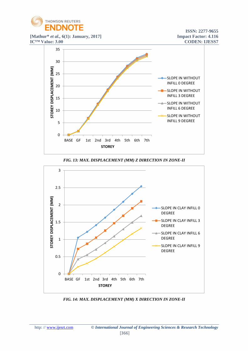
FIG. 13: MAX. DISPLACEMENT (MM) Z DIRECTION IN ZONE-II
FIG. 14: MAX. DISPLACEMENT (MM) X DIRECTION IN ZONE-II
0
5
10
15
20
25
30
35
BASE GF 1st 2nd 3rd 4th 5th 6th 7th
STO
REY
DIS
PLA
CEM
ENT
(MM
)
STOREY
SLOPE IN WITHOUTINFILL 0 DEGREE
SLOPE IN WITHOUTINFILL 3 DEGREE
SLOPE IN WITHOUTINFILL 6 DEGREE
SLOPE IN WITHOUTINFILL 9 DEGREE
0
0.5
1
1.5
2
2.5
3
BASE GF 1st 2nd 3rd 4th 5th 6th 7th
STO
REY
DIS
PLA
CEM
ENT
(MM
)
STOREY
SLOPE IN CLAY INFILL 0DEGREE
SLOPE IN CLAY INFILL 3DEGREE
SLOPE IN CLAY INFILL 6DEGREE
SLOPE IN CLAY INFILL 9DEGREE
ISSN: 2277-9655
[Mathur* et al., 6(1): January, 2017] Impact Factor: 4.116
IC™ Value: 3.00 CODEN: IJESS7
http: // www.ijesrt.com © International Journal of Engineering Sciences & Research Technology
[367]
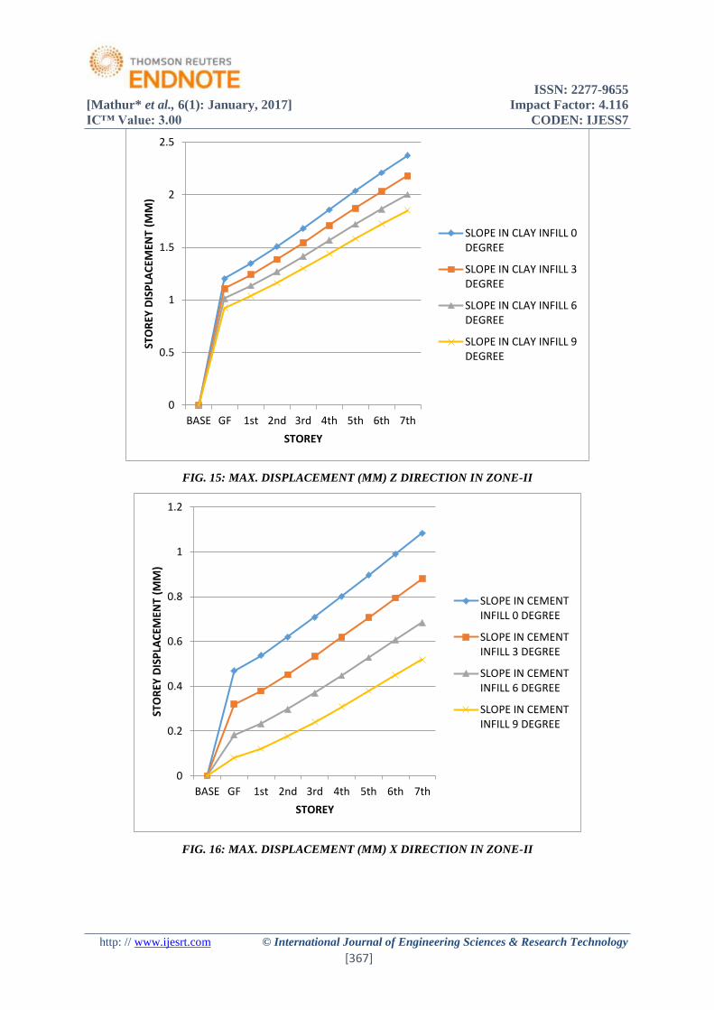
FIG. 15: MAX. DISPLACEMENT (MM) Z DIRECTION IN ZONE-II
FIG. 16: MAX. DISPLACEMENT (MM) X DIRECTION IN ZONE-II
0
0.5
1
1.5
2
2.5
BASE GF 1st 2nd 3rd 4th 5th 6th 7th
STO
REY
DIS
PLA
CEM
ENT
(MM
)
STOREY
SLOPE IN CLAY INFILL 0DEGREE
SLOPE IN CLAY INFILL 3DEGREE
SLOPE IN CLAY INFILL 6DEGREE
SLOPE IN CLAY INFILL 9DEGREE
0
0.2
0.4
0.6
0.8
1
1.2
BASE GF 1st 2nd 3rd 4th 5th 6th 7th
STO
REY
DIS
PLA
CEM
ENT
(MM
)
STOREY
SLOPE IN CEMENTINFILL 0 DEGREE
SLOPE IN CEMENTINFILL 3 DEGREE
SLOPE IN CEMENTINFILL 6 DEGREE
SLOPE IN CEMENTINFILL 9 DEGREE
ISSN: 2277-9655
[Mathur* et al., 6(1): January, 2017] Impact Factor: 4.116
IC™ Value: 3.00 CODEN: IJESS7
http: // www.ijesrt.com © International Journal of Engineering Sciences & Research Technology
[368]
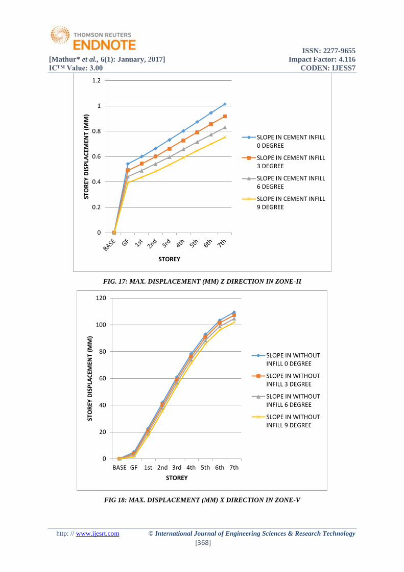
FIG. 17: MAX. DISPLACEMENT (MM) Z DIRECTION IN ZONE-II
FIG 18: MAX. DISPLACEMENT (MM) X DIRECTION IN ZONE-V
0
0.2
0.4
0.6
0.8
1
1.2ST
OR
EY D
ISP
LAC
EMEN
T (M
M)
STOREY
SLOPE IN CEMENT INFILL0 DEGREE
SLOPE IN CEMENT INFILL3 DEGREE
SLOPE IN CEMENT INFILL6 DEGREE
SLOPE IN CEMENT INFILL9 DEGREE
0
20
40
60
80
100
120
BASE GF 1st 2nd 3rd 4th 5th 6th 7th
STO
REY
DIS
PLA
CEM
ENT
(MM
)
STOREY
SLOPE IN WITHOUTINFILL 0 DEGREE
SLOPE IN WITHOUTINFILL 3 DEGREE
SLOPE IN WITHOUTINFILL 6 DEGREE
SLOPE IN WITHOUTINFILL 9 DEGREE
ISSN: 2277-9655
[Mathur* et al., 6(1): January, 2017] Impact Factor: 4.116
IC™ Value: 3.00 CODEN: IJESS7
http: // www.ijesrt.com © International Journal of Engineering Sciences & Research Technology
[369]
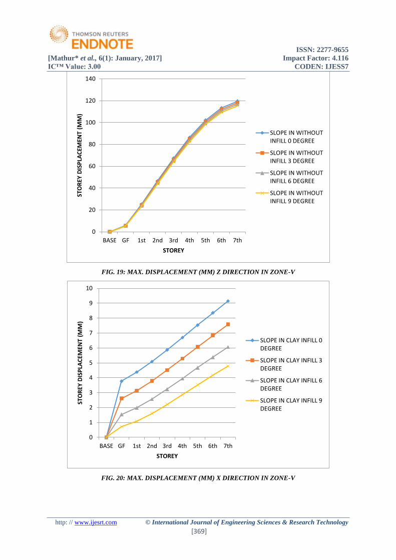
FIG. 19: MAX. DISPLACEMENT (MM) Z DIRECTION IN ZONE-V
FIG. 20: MAX. DISPLACEMENT (MM) X DIRECTION IN ZONE-V
0
20
40
60
80
100
120
140
BASE GF 1st 2nd 3rd 4th 5th 6th 7th
STO
REY
DIS
PLA
CEM
ENT
(MM
)
STOREY
SLOPE IN WITHOUTINFILL 0 DEGREE
SLOPE IN WITHOUTINFILL 3 DEGREE
SLOPE IN WITHOUTINFILL 6 DEGREE
SLOPE IN WITHOUTINFILL 9 DEGREE
0
1
2
3
4
5
6
7
8
9
10
BASE GF 1st 2nd 3rd 4th 5th 6th 7th
STO
REY
DIS
PLA
CEM
ENT
(MM
)
STOREY
SLOPE IN CLAY INFILL 0DEGREE
SLOPE IN CLAY INFILL 3DEGREE
SLOPE IN CLAY INFILL 6DEGREE
SLOPE IN CLAY INFILL 9DEGREE
ISSN: 2277-9655
[Mathur* et al., 6(1): January, 2017] Impact Factor: 4.116
IC™ Value: 3.00 CODEN: IJESS7
http: // www.ijesrt.com © International Journal of Engineering Sciences & Research Technology
[370]
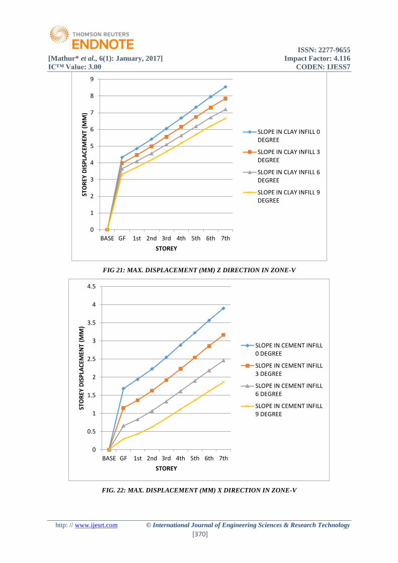
FIG 21: MAX. DISPLACEMENT (MM) Z DIRECTION IN ZONE-V
FIG. 22: MAX. DISPLACEMENT (MM) X DIRECTION IN ZONE-V
0
1
2
3
4
5
6
7
8
9
BASE GF 1st 2nd 3rd 4th 5th 6th 7th
STO
REY
DIS
PLA
CEM
ENT
(MM
)
STOREY
SLOPE IN CLAY INFILL 0DEGREE
SLOPE IN CLAY INFILL 3DEGREE
SLOPE IN CLAY INFILL 6DEGREE
SLOPE IN CLAY INFILL 9DEGREE
0
0.5
1
1.5
2
2.5
3
3.5
4
4.5
BASE GF 1st 2nd 3rd 4th 5th 6th 7th
STO
REY
DIS
PLA
CEM
ENT
(MM
)
STOREY
SLOPE IN CEMENT INFILL0 DEGREE
SLOPE IN CEMENT INFILL3 DEGREE
SLOPE IN CEMENT INFILL6 DEGREE
SLOPE IN CEMENT INFILL9 DEGREE
ISSN: 2277-9655
[Mathur* et al., 6(1): January, 2017] Impact Factor: 4.116
IC™ Value: 3.00 CODEN: IJESS7
http: // www.ijesrt.com © International Journal of Engineering Sciences & Research Technology
[371]
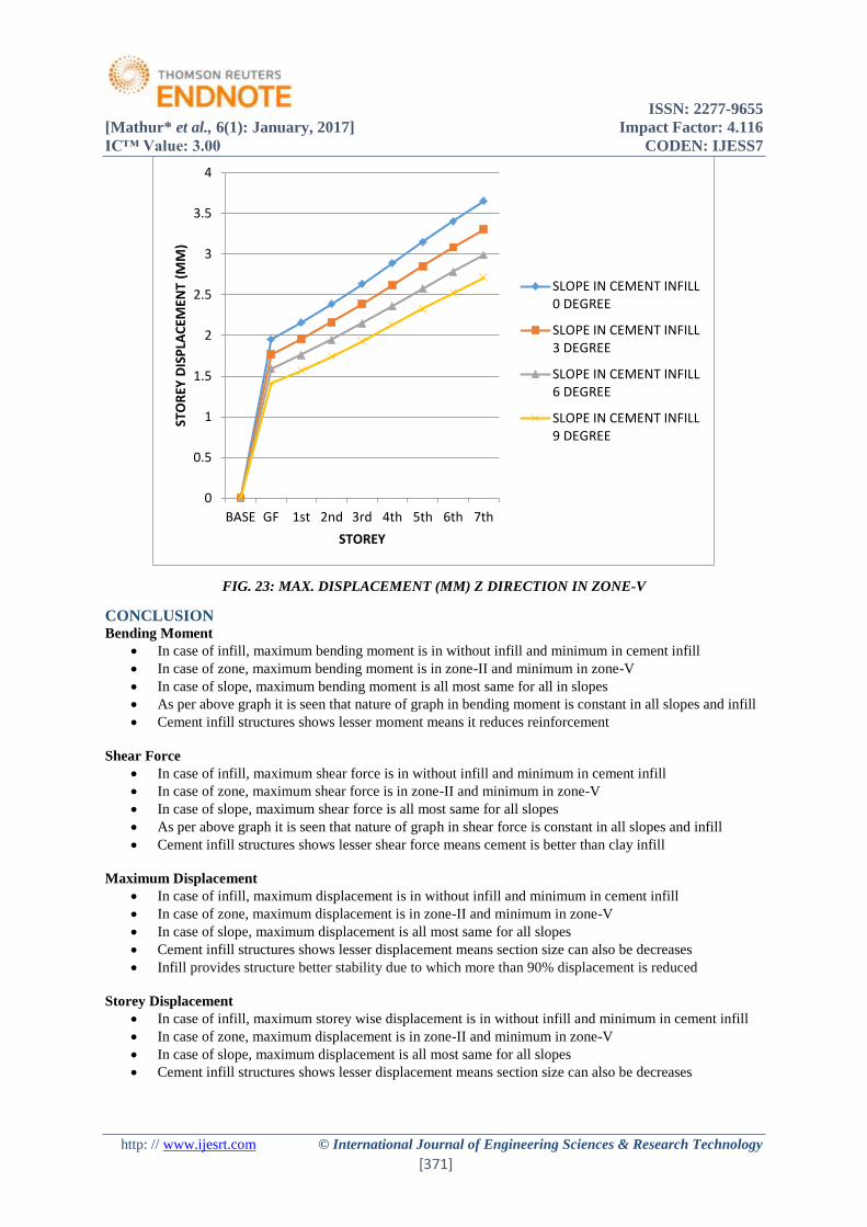
FIG. 23: MAX. DISPLACEMENT (MM) Z DIRECTION IN ZONE-V
CONCLUSION Bending Moment
In case of infill, maximum bending moment is in without infill and minimum in cement infill
In case of zone, maximum bending moment is in zone-II and minimum in zone-V
In case of slope, maximum bending moment is all most same for all in slopes
As per above graph it is seen that nature of graph in bending moment is constant in all slopes and infill
Cement infill structures shows lesser moment means it reduces reinforcement
Shear Force
In case of infill, maximum shear force is in without infill and minimum in cement infill
In case of zone, maximum shear force is in zone-II and minimum in zone-V
In case of slope, maximum shear force is all most same for all slopes
As per above graph it is seen that nature of graph in shear force is constant in all slopes and infill
Cement infill structures shows lesser shear force means cement is better than clay infill
Maximum Displacement
In case of infill, maximum displacement is in without infill and minimum in cement infill
In case of zone, maximum displacement is in zone-II and minimum in zone-V
In case of slope, maximum displacement is all most same for all slopes
Cement infill structures shows lesser displacement means section size can also be decreases
Infill provides structure better stability due to which more than 90% displacement is reduced
Storey Displacement
In case of infill, maximum storey wise displacement is in without infill and minimum in cement infill
In case of zone, maximum displacement is in zone-II and minimum in zone-V
In case of slope, maximum displacement is all most same for all slopes
Cement infill structures shows lesser displacement means section size can also be decreases
0
0.5
1
1.5
2
2.5
3
3.5
4
BASE GF 1st 2nd 3rd 4th 5th 6th 7th
STO
REY
DIS
PLA
CEM
ENT
(MM
)
STOREY
SLOPE IN CEMENT INFILL0 DEGREE
SLOPE IN CEMENT INFILL3 DEGREE
SLOPE IN CEMENT INFILL6 DEGREE
SLOPE IN CEMENT INFILL9 DEGREE
ISSN: 2277-9655
[Mathur* et al., 6(1): January, 2017] Impact Factor: 4.116
IC™ Value: 3.00 CODEN: IJESS7
http: // www.ijesrt.com © International Journal of Engineering Sciences & Research Technology
[372]
It can be concluded from the study that the value of various distractive parameter namely maximum displacement,
storey displacement, maximum bending moment and maximum shear force that infill is best and efficient pattern
because these parameter are lowest in this case further based on same line we can conclude that cement infill best
and clay second best, whereas without infill structure can be termed as critical structure. And in case of slope it is
observed that above parameters are slightly varying as slope increases. Although the dead weight of the structure
increases with infill but it increases the stiffness of the structure which is an important factor in seismic design of
structures.
SCOPE FOR FUTURE STUDY In present study slopes are increased in multiple of 3 but it can further increase in multiple of 5 or 10.
In this study fixed supports are used further pinned can be prefer
Two type of infill are analyse in further study can be analysed with various infills
Seismic analysis is done it can be analyse in wind loading also
REFERENCES [1] Marina L. Moretti, “Seismic Design of Masonry and Reinforced Concrete Infilled Frames: A
Comprehensive Overview”, American Journal of Engineering and Applied Sciences, vol. 4 pp 748-766.
2016
[2] Qunxian Huang , Zixiong Guo , J.S. Kuang, “Designing of infill reinforced concrete frames with the
method used is ‘strong frame-weak infill’”, Engineering Structure, vol. 123, pp 341-353, 11th June 2016.
[3] Aslam Faqeer Mohammad, Marco Faggella , Rosario Gigliotti , Enrico Spacone, “Seismic analysis of
older R/C frame structures accounting for infill on inducing shear failure of columns”, Engineering
Structure, vol. 122, pp 1-13, 24th may 2016.
[4] Alessandra Fiore, Girolamo Spagnoletti , Rita Greco, “On the prediction of shear brittle collapse
mechanisms due to the infill-frame interaction in RC buildings under pushover analysis”, Engineering
Structure, vol. 121, pp 147-159,10th may 2016.
[5] Syed Humayun Basha, Hemant B. Kaushik, “nature and failure mechanisms of infilled RC frames (in
low-rise buildings) subject to lateral loading”, Engineering Structure, vol. 111, pp 233-245, 6th jan 2016.
[6] Sidi Shan, Shuang Li , Shiyu Xu , Lili Xie, “Experimental study on the progressive collapse performance
of RC frames with infill walls”,Engineering Structure, vol. 111, pp 80-92, 6th jan 2016.
[7] Preti M, Bettini N, Migliorati L, Bolis V, Stavridis A, Plizzari GA., “Analysis of the in-plane response
of earthen masonry infill panels partitioned by sliding joints”, Earthquake Engineering and Structural
Dynamics, vol. 58, pp 84-92, 2016.
[8] ShuangyangLi,YuanmingLai n, MingyiZhang,WenbingYu, “Seasonal differences in seismic responses
on a sloping ground in permafrost regions in State Key of Frozen Soil Engineering”, Soil Dynamics
and Earthquake Engineering, vol. 76, pp 122-135, 14th Feb 2015.
[9] Ivo Caliò , Bartolomeo Pantò, “A macro-element modelling approach of Infilled Frame Structures
Computers and Structures”, vol 143, pp 91-107, 12th Aug 2015
[10] F. Vieux-Champagne, Y. Sieffert , S. Grange, A. Polstri, A. Cecotti , L. Daudeville, “Practical result of
seismic resistance of timber-framed structures with stones and earth infill”, vol. 69, 5th April 2014.
[11] Humbert J, Boudaud C, Baroth J, Hameury S, Daudeville L, “ Multi-scalemodelling of wood shear walls.
I: Calibration and validation under quasi-static reversed-cyclic loading”, Engineering Structures, vol. 65,
pp 52-61, 2014.
[12] Putul Haldar , Yogendra Singh , D.K. Paul, “Identification of seismic failure modes of URM infilled RC
frame buildings” , Engineering Failure Analysis, pp 97-118, 7th may 2013.
[13] Sucuog˘lu H, “ Implications of masonry infill and partition damage in performance perception in
residential buildings after a moderate earthquake”, Earthquake Spectra, vol.6, pp 18-27,2013
[14] Misir S, Ozcelik O, Girgin SA, Kahraman S. “ Practical work on seismic nature of many type infilled
RC frames”, Structural Engineering Mechanism, vol. 12, pp 73–74 , 2012.
[15] Vicente RS, Rodriges H, Varum H, Costa A, Mendis da Silva AR, “ Analysis of masonry enclosure
walls: lessons learned from recent earthquakes”, Earthquake Engineering and Engineering Vibration,
vol. 11, pp 23–34, 2012.
[16] J.F. Rave-Arango & C.A. Blandon Uribe, “Structural response of building on mountain slopes subjected
to earth pressure under seismic conditions”,Engineering Structure, vol.28 pp 11-19. 2012.
[17] Kakaletsis DJ, Karayannis CG. “Influence of masonry strength and openings on infilled R/C frames
under cycling loading”, Earthquake Engineering, vol. 2, pp 197–221, 2008.

ISSN: 2277-9655
[Mathur* et al., 6(1): January, 2017] Impact Factor: 4.116
IC™ Value: 3.00 CODEN: IJESS7
http: // www.ijesrt.com © International Journal of Engineering Sciences & Research Technology
[373]
[18] Aliaari M, Memari AM., “Experimental evaluation of a sacrificial seismic fuse device for masonry infill
walls”, ASCE Journal of Architectural Engineering, vol. 13, pp111–125, 2007.
[19] Kaushik HB, Rai DC, Jain SK. “Stress-strain advantage of clay brick masonry under uniaxial
compression”.,Civil Eng ASCE, vol. 9, pp 728–739, 2007.
[20] Baris Binici a,*, Guney Ozcebe a,1, Ramazan Ozcelik ,“study and design of fibre reinforcrd polymer
composites for seismic retrofitting of infill walls in reinforced concrete frames” Engineering structure,
vol. 38, pp 575–583, 21st Dec 2006.
[21] Aliaari M, Memari AM, “Analysis of masonry infilled steel frames with seismic isolator subframes”,
Engineering Structure, vol. 56, pp 487–500, 2005.
[22] IS 1893 (part 1), “Criteria for Earthquake resistant design of structures”, Bureau Of Indian Standards,
New Delhi,2002.
[23] IS:456, “Indian Standard Code Of Practice For Plain And Reinforced Concrete,” Bureau Of Indian
Standards, New Delhi.2000.