Embed Size (px)
Citation preview
Bollettino di Geofisica Teorica ed Applicata Vol. 55, n. 1, pp. 103-118; March 2014
DOI 10.4430/bgta0093
103
Seismic analysis of an isolated and a non-isolated light-frame timber building using artificial and natural accelerograms
L. Sancin1, G. RinaLdin2, M. FRaGiacoMo1 and c. aMadio2
1 Dept. of Architecture, Design and Urban Planning, University of Sassari, Alghero, Italy2 Dept. of Civil Engineering and Architecture, University of Trieste, Italy
(Received: May 27, 2012; accepted: March 27, 2013)
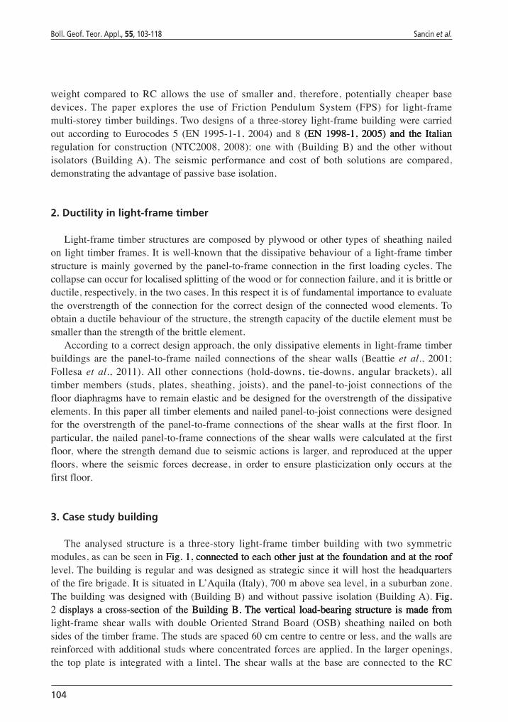
ABSTRACT Light-frameconstructionisusedextensivelyforlowandmediumrisetimberbuildings.Thesebuildingsarelight-weightandhaveahighdissipativecapacitywhich,ontheother hand, may imply significant structural and non-structural damage at the end of a high intensity earthquake ground motion, leading to potentially significant economic losses.Passivebaseisolationisbyfarthemosteffectivewaytoreducetheeffectofanearthquakeonastructure.Inthispaper,theuseofFrictionPendulumSystemisolatorsis investigated for a three-storey light-frame timber building. Two designs of thesamebuilding,withandwithoutpassivebaseisolation,werecarriedoutaccordingtoEurocodes5and8andtheItaliantechnicalregulationforconstruction.Thebuildingswerethenanalysedusinglinearandnon-linearmethods.Theseismicperformanceandcostofbothsolutionsarecompared,demonstratingtheconvenienceofusingpassivebaseisolation.
Key words: timber building, light-frame construction, non-linear analysis, seismic design, passive baseisolation.
© 2014 – OGS
1. Introduction
According to the modern philosophy of the DamageAvoidance Design (DAD) (ManderandCheng, 1997;Bradleyet al., 2008), a structure shouldbedesignednot only to survive ahighintensityearthquakegroundmotion,butalsotominimizethestructuralandnon-structuraldamage. Passive base isolation is by far the most effective way to reduce the consequencesof an earthquake on an existing or new structure (Zayas et al., 1990; Mezzi and Parducci,1998). Its use has been somewhat limited by the cost, which is often believed to be high.However, significant progress has been made in this decade on passive base isolation, andnowadays the cost of this technique has markedly reduced. For these reasons, passive baseisolationsystemswererecentlyusedalsoforresidentialapplications.Forexample,inL’Aquila(Italy) both reinforced concrete (RC) and timber buildings built after the 2009 earthquakewerebase isolated.Theeffectivenessofpassivebase isolationwasdemonstratedat lengthbythe earthquakesoccurred inLosAngeles in1994and inKobe in1995,where adramaticallydifferent performance was observed in isolated and non-isolated buildings. It is therefore ofinterest to investigate this option also for timber buildings, where the significantly reduced
104
Boll. Geof. Teor. Appl., 55, 103-118 Sancin et al.
weight compared to RC allows the use of smaller and, therefore, potentially cheaper basedevices. The paper explores the use of Friction Pendulum System (FPS) for light-framemulti-storey timberbuildings.Twodesignsofa three-storey light-framebuildingwerecarriedout according to Eurocodes 5 (EN 1995-1-1, 2004) and 8 (EN 1998-1, 2005) and the Italian(EN 1998-1, 2005) and the ItalianEN 1998-1, 2005) and the Italianregulation for construction (NTC2008, 2008): one with (Building B) and the other withoutisolators (BuildingA).The seismic performance and cost of both solutions are compared,demonstratingtheadvantageofpassivebaseisolation.
2. Ductility in light-frame timber
Light-frametimberstructuresarecomposedbyplywoodorother typesofsheathingnailedonlight timberframes.It iswell-knownthat thedissipativebehaviourofa light-frametimberstructure ismainlygovernedby thepanel-to-frameconnection in thefirst loadingcycles.Thecollapsecanoccurforlocalisedsplittingofthewoodorforconnectionfailure,anditisbrittleorductile,respectively,inthetwocases.Inthisrespectitisoffundamentalimportancetoevaluatetheoverstrengthof theconnection for thecorrectdesignof theconnectedwoodelements.Toobtainaductilebehaviourofthestructure,thestrengthcapacityoftheductileelementmustbesmallerthanthestrengthofthebrittleelement.
Accordingtoacorrectdesignapproach,theonlydissipativeelementsinlight-frametimberbuildings are the panel-to-frame nailed connections of the shear walls (Beattie et al., 2001;Follesa et al., 2011).All other connections (hold-downs, tie-downs, angular brackets), alltimber members (studs, plates, sheathing, joists), and the panel-to-joist connections of thefloordiaphragmshavetoremainelasticandbedesignedfortheoverstrengthofthedissipativeelements.Inthispaperalltimberelementsandnailedpanel-to-joistconnectionsweredesignedfor the overstrength of the panel-to-frameconnections of the shear walls at the first floor. Inparticular, thenailedpanel-to-frameconnectionsof theshearwallswerecalculatedat thefirstfloor,wherethestrengthdemandduetoseismicactionsislarger,andreproducedattheupperfloors, where the seismic forces decrease, in order to ensure plasticization only occurs at thefirstfloor.
3. Case study building
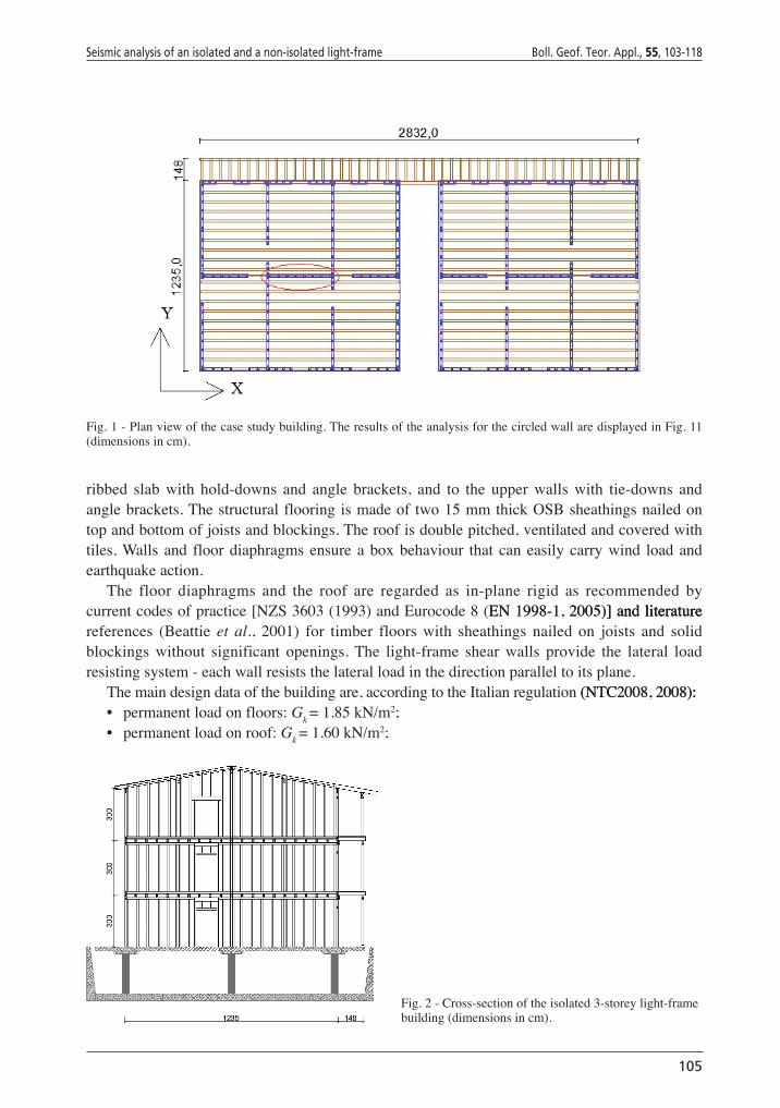
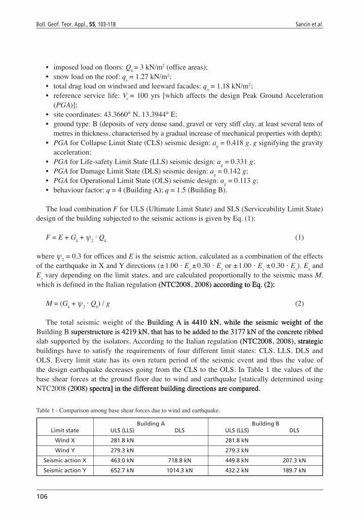
The analysed structure is a three-story light-frame timber building with two symmetricmodules,ascanbeseeninFig. 1, connected to each other just at the foundation and at the roofFig.1, connected to each other just at the foundation and at the roof,connectedtoeachotherjustatthefoundationandattherooflevel.Thebuildingisregularandwasdesignedasstrategicsinceitwillhost theheadquartersofthefirebrigade.ItissituatedinL’Aquila(Italy),700mabovesealevel,inasuburbanzone.Thebuildingwasdesignedwith(BuildingB)andwithoutpassive isolation(BuildingA).Fig.Fig.2 displays a cross-section of the Building B. The vertical load-bearing structure is made fromdisplaysacross-sectionof theBuilding B. The vertical load-bearing structure is made fromBuildingB. The vertical load-bearing structure is made from.Thevertical load-bearingstructure ismadefromlight-frame shear walls with double Oriented Strand Board (OSB) sheathing nailed on bothsidesofthetimberframe.Thestudsarespaced60cmcentretocentreorless,andthewallsarereinforcedwithadditionalstudswhereconcentratedforcesareapplied.Inthelargeropenings,the top plate is integrated with a lintel.The shear walls at the base are connected to the RC
Seismic analysis of an isolated and a non-isolated light-frame Boll. Geof. Teor. Appl., 55, 103-118
105
Fig.1-Planviewofthecasestudybuilding.TheresultsoftheanalysisforthecircledwallaredisplayedinFig.11(dimensionsincm).
ribbed slab with hold-downs and angle brackets, and to the upper walls with tie-downs andanglebrackets.Thestructuralflooringismadeoftwo15mmthickOSBsheathingsnailedontopandbottomofjoistsandblockings.Theroofisdoublepitched,ventilatedandcoveredwithtiles.Walls and floordiaphragmsensureaboxbehaviour that caneasilycarrywind loadandearthquakeaction.
The floor diaphragms and the roof are regarded as in-plane rigid as recommended bycurrentcodesofpractice[NZS3603(1993)andEurocode8(EN 1998-1, 2005)�� and literatureEN1998-1,2005)�� and literature��andliteraturereferences (Beattie et al., 2001) for timber floors with sheathings nailed on joists and solidblockings without significant openings.The light-frame shear walls provide the lateral loadresistingsystem-eachwallresiststhelateralloadinthedirectionparalleltoitsplane.
Themaindesigndataofthebuildingare,accordingtotheItalianregulation(NTC2008, 2008):(NTC2008,2008)::• permanentloadonfloors:Gk =1.85kN/m2;• permanentloadonroof:Gk =1.60kN/m2;
Fig.2-Cross-sectionoftheisolated3-storeylight-framebuilding(dimensionsincm).
106
Boll. Geof. Teor. Appl., 55, 103-118 Sancin et al.
• imposedloadonfloors:Qk =3kN/m2(officeareas);• snowloadontheroof:qs =1.27kN/m2;• totaldragloadonwindwardandleewardfacades:qw =1.18kN/m2;• reference service life: Vr = 100 yrs [which affects the design Peak GroundAcceleration
(PGA)��;• sitecoordinates:43.3660°N,13.3944°E;• groundtype:B(depositsofverydensesand,gravelorverystiffclay,atleastseveraltensof
metresinthickness,characterisedbyagradualincreaseofmechanicalpropertieswithdepth);• PGAforCollapseLimitState(CLS)seismicdesign:ag =0.418g,gsignifyingthegravity
acceleration;• PGAforLife-safetyLimitState(LLS)seismicdesign:ag =0.331g;• PGAforDamageLimitState(DLS)seismicdesign:ag =0.142g;• PGAforOperationalLimitState(OLS)seismicdesign:ag =0.113g;• behaviourfactor:q=4(BuildingA);q=1.5(BuildingB).
TheloadcombinationFforULS(UltimateLimitState)andSLS(ServiceabilityLimitState)designofthebuildingsubjectedtotheseismicactionsisgivenbyEq.(1):
F=E+Gk+ψ2·Qk (1)
whereψ2=0.3forofficesandEistheseismicaction,calculatedasacombinationoftheeffectsoftheearthquakeinXandYdirections(±1.00·Ex ±0.30· Eyor±1.00· Ey±0.30· Ex).ExandEyvarydependingonthelimitstates,andarecalculatedproportionallytotheseismicmassM,whichisdefinedintheItalianregulation(NTC2008, 2008) according to Eq. (2):(NTC2008,2008) according to Eq. (2):accordingtoEq.(2):
M=(Gk+ψ2·Qk)/g (2)
The total seismic weight of the Building A is 4410 kN, while the seismic weight of theBuildingA is 4410 kN, while the seismic weight of the is 4410 kN, while the seismic weight of theBuildingB superstructure is 4219 kN, that has to be added to the 3177 kN of the concrete ribbedsuperstructureis4219kN,thathastobeaddedtothe3177kNoftheconcreteribbedslabsupportedbytheisolators.AccordingtotheItalianregulation(NTC2008, 2008), strategic(NTC2008,2008), strategic,strategicbuildings have to satisfy the requirements of four different limit states: CLS, LLS, DLS andOLS. Every limit state has its own return period of the seismic event and thus the value ofthedesignearthquakedecreasesgoingfromtheCLSto theOLS.InTable1 thevaluesof thebaseshear forcesat thegroundfloordue towindandearthquake[staticallydeterminedusingNTC2008(2008) spectra�� in the different building directions are compared.(2008)spectra�� in the different building directions are compared.spectra��inthedifferentbuildingdirectionsarecompared.
Building A Building B Limit state ULS (LLS) DLS ULS (LLS) DLS
Wind X 281.8 kN 281.8 kN
Wind Y 279.3 kN 279.3 kN
Seismic action X 463.0 kN 718.8 kN 449.8 kN 207.3 kN
Seismic action Y 652.7 kN 1014.3 kN 432.2 kN 189.7 kN
Table1-Comparisonamongbaseshearforcesduetowindandearthquake.
Seismic analysis of an isolated and a non-isolated light-frame Boll. Geof. Teor. Appl., 55, 103-118
107
4. Seismic isolation
After designing the Building A, the same building was re-designed with passive baseBuildingA, the same building was re-designed with passive base, the same building was re-designed with passive baseisolation (BuildingB).Thebase floordiaphragmconnecting the twomodulesof thebuildingandsupportedbytheisolationdevicesismadeofaribbedRCslab.Theisolatorsaresupportedbystiffconcretecolumnsconnectedtoaflatplatefoundation.Inthiswayitispossibletoobtainabasementthatcanbeusedasagarage,astypicallyrequiredbyarchitecturalconsiderations.Atthesametime,accordingtotheItalianregulation(NTC2008, 2008), the compulsory requirement(NTC2008,2008), the compulsory requirement,thecompulsoryrequirementofensuringaneasymaintenanceandsubstitutionoftheisolationdevicescanbesatisfied.
4.1. Friction pendulum systemDoubleFrictionPendulumSystemunits(FPS)havebeenusedinthispaperasbaseisolation
(Zayaset al.,1990;Constantinou,2004;FenzandConstantinou,2006).Theyarecurvedsurfaceslidingisolatorswhichexploitgravityforre-centring,likeapendulum.Dissipationoftheinputseismic energy takes place due to the friction on the main surface.The parameters of theircyclicbehaviourdependon the curvature andon the frictioncoefficient.After the activation,thedevicedevelopsalateralforceFdin thatisgiveninEq.(3)bytheresultantofthedynamicfrictionforceandtherestoringforceduetogravity:
WFdin=–––u+µdinW (3) R
whereFdinisthelateralforcedevelopedbytheisolatorinaction;Wistheweightofthetimbersuperstructureandbasefloordiaphragmabovetheunit;µdinisthedynamicfrictioncoefficient;Ristheradiusofcurvatureoftheisolatorconcavesurface,anduistheisolatordisplacement.
Thecurvature radius is an importantparameter in these system, as it governs the stiffnessandthereforethenaturalvibrationperiodoftheisolatedstructure.TheperiodTofarigidmasssupportedbyaFPSisolatorcanbecalculatedasinEq.(4)(FIPIndustriale,2010):
(4)
wheregisthegravityaccelerationandudisthedesigndisplacement.The equivalent lateral stiffness ke of an active FPS isolator, relative to the maximum
displacementumax,isinverselyproportionaltothecurvatureradiusR,ascanbeseeninEq.(5)(FIPIndustriale,2010):
(5)
where the symbols have the same meaning as before.The direct proportion of the systemstiffness to the weight bearing on it is fundamental for avoiding torsional problems in the
108
Boll. Geof. Teor. Appl., 55, 103-118 Sancin et al.
seismicresponseof thestructure.In thiswaythestiffnesscentrecoincidesautomaticallywiththemasscentre.
4.2. Design of the isolatorsTheBuilding B is designed for the same gravity and wind load as Building A, but the seismicBuildingB is designed for the same gravity and wind load as Building A, but the seismicisdesignedforthesamegravityandwindloadasBuildingA,buttheseismic
forces are smaller. Indeed, the isolation system was designed to obtain a natural vibrationperiodT1 = 2.93 s,correspondingto thefinalpartof thedesignresponsespectrum,wheretheaccelerationsarelesscritical.Asaresultofthat,thesuperstructureofBuilding B is lighter, withBuildingB is lighter, withislighter,withsmallercross-sectionsandwith lessnails requiredcompared toBuildingA.AcomparisonforthemostsignificantvibrationperiodsandtheirmassparticipationratiosisshowninTable2.
Building A Building B
T [s] Direction Participating T [s] Direction Participating mass ratio mass ratio
1.00 X 90.0% 2.86 Y 99.7%
0.71 Y 82.7% 2.76 X 99.6%
Table 2 - Comparison among vibration periods for fixed base (Building A) and isolated (Building B) and related mass participationratios.
Thedesignoftheisolatorsiscarriedoutsoastocomplywithtwoperformancerequirements:i) the isolator should work (move) for the CLS and LLS design levels of earthquake groundmotion; and ii) the isolator should behave like a fixed restraint for the design wind load atultimatelimitstate.Thefirstconditionensuresthattheisolatorspreventanystructuraldamage,according to theDADphilosophy.The seconddesign condition is fundamental for the livingcomfort, as the wind occurs quite often and the waving motion of the isolators may causeseasickness of the occupants. Moreover, the continuous functioning of the isolators wouldlead to amajorusuryof theunits and reduced safety level in thecaseof anearthquake.Thedisplacementdemandoftheisolationsystemwascalculatedtobearound200mmatCLS,sothatthechosendevicewasadoublecurvedsurfaceFPS,withthefollowingproperties:
• verticalload-carryingcapacity:1000kN;• radiusoftheslidingsurface:2535mm;• dynamicfrictioncoefficient:0.025;• maximumdesigndisplacement:200mm;• equivalent viscous damping coefficient (corresponding to the maximum design
displacement):15.3%;• naturalperiod(correspondingtothemaximumdesigndisplacement):2.78s• diameter(withoutanchorage):430mm;• depth(withoutanchorage):89mm.
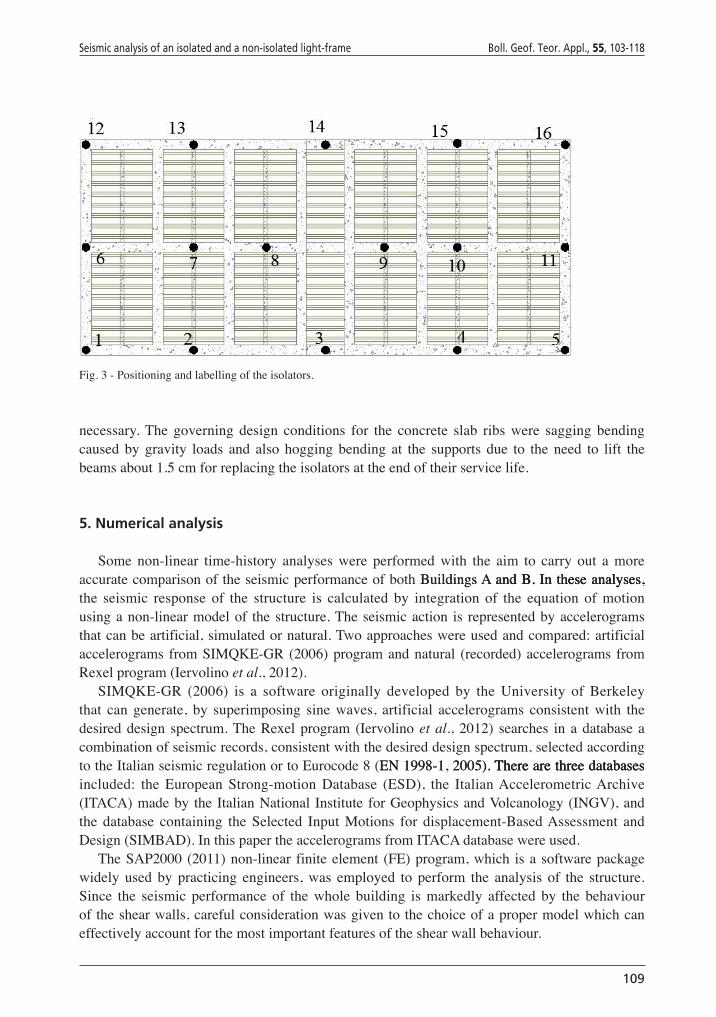
ThepositioningoftheFPSsisshowninFig. 3. The maximum distance between the devicesFig.3.The maximum distance between the devicesThemaximumdistancebetweenthedevicesisalmost8m.Thelimitingfactorindecidingthemaximumdistancewasthebendingresistanceoftheconcreteslabribsandnotthecapacityoftheisolationdevices,whichismuchlargerthan
Seismic analysis of an isolated and a non-isolated light-frame Boll. Geof. Teor. Appl., 55, 103-118
109
necessary.The governing design conditions for the concrete slab ribs were sagging bendingcaused by gravity loads and also hogging bending at the supports due to the need to lift thebeamsabout1.5cmforreplacingtheisolatorsattheendoftheirservicelife.
5. Numerical analysis
Some non-linear time-history analyses were performed with the aim to carry out a moreaccuratecomparisonoftheseismicperformanceofbothBuildings A and B. In these analyses,BuildingsA and B. In these analyses,andB.Intheseanalyses,the seismic response of the structure is calculated by integration of the equation of motionusinganon-linearmodelof thestructure.Theseismicaction is representedbyaccelerogramsthatcanbeartificial,simulatedornatural.Twoapproacheswereusedandcompared:artificialaccelerograms fromSIMQKE-GR(2006)programandnatural (recorded)accelerograms fromRexelprogram(Iervolinoet al.,2012).
SIMQKE-GR (2006) is a software originally developed by the University of Berkeleythat can generate, by superimposing sine waves, artificial accelerograms consistent with thedesireddesign spectrum.TheRexelprogram (Iervolinoet al., 2012) searches in adatabase acombinationofseismicrecords,consistentwiththedesireddesignspectrum,selectedaccordingtotheItalianseismicregulationortoEurocode8(EN 1998-1, 2005). There are three databasesEN1998-1,2005). There are three databases.Therearethreedatabasesincluded: the European Strong-motion Database (ESD), the ItalianAccelerometricArchive(ITACA)madeby theItalianNational Institute forGeophysicsandVolcanology(INGV),andthe database containing the Selected Input Motions for displacement-BasedAssessment andDesign(SIMBAD).InthispapertheaccelerogramsfromITACAdatabasewereused.
TheSAP2000(2011)non-linear finiteelement (FE)program,which isasoftwarepackagewidely used by practicing engineers, was employed to perform the analysis of the structure.Since the seismic performance of the whole building is markedly affected by the behaviouroftheshearwalls,carefulconsiderationwasgiventothechoiceofapropermodelwhichcaneffectivelyaccountforthemostimportantfeaturesoftheshearwallbehaviour.
Fig.3-Positioningandlabellingoftheisolators.
110
Boll. Geof. Teor. Appl., 55, 103-118 Sancin et al.
5.1. FE modelling of light-frame shear wallsThebehaviouroflight-frametimbershearwallsisfairlycomplexastheyarecomposedby
differentelements: timberframe,sheathingandconnections(panel-to-framenailedconnectionand anchoring of the wall to the foundation or to the floor underneath).All these elementscontributetothetotalflexibilityofthewall,whichaffectsthedistributionofhorizontal(seismicand wind) forces within the building.The need to model an entire three-storey building hassuggested theopportunity to use amacro-modelwhere all flexibility components are lumpedtogether,ratherthandevelopingacomputationallydemandingschematizationwhereallflexibleelements(forexample,eachnailoftheframe-to-panelconnection)areexplicitlymodelled.
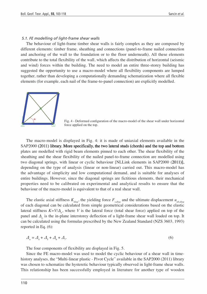
Fig. 4 - Deformed configuration of the macro-model of the shear wall under horizontal forceappliedonthetop.
The macro-model is displayed in Fig. 4: it is made of uniaxial elements available in theSAP2000(2011) library. More specifically, the two lateral studs (chords) and the top and bottom(2011) library. More specifically, the two lateral studs (chords) and the top and bottomlibrary.Morespecifically,thetwolateralstuds(chords)andthetopandbottomplatesaremodelledwithrigidbeamelementspinnedtoeachother.Theshearflexibilityofthesheathingand theshearflexibilityof thenailedpanel-to-frameconnectionaremodelledusingtwodiagonal springs,with linearor cyclicbehaviour [NLLinkelements inSAP2000 (2011)��,2011)��,)��,depending on the type of analysis (linear or non-linear) carried out.This macro-model hasthe advantage of simplicity and low computational demand, and is suitable for analyses ofentirebuildings.However, since thediagonal springsare fictitiouselements, theirmechanicalproperties need to be calibrated on experimental and analytical results to ensure that thebehaviourofthemacro-modelisequivalenttothatofarealshearwall.
TheelasticaxialstiffnessKdiag,theyieldingforceFy,diagandtheultimatedisplacementuult,diagofeachdiagonalcanbecalculatedfromsimplegeometricalconsiderationsbasedontheelasticlateral stiffnessK=V/∆w,whereV is the lateral force (total shear force) appliedon topof thepaneland∆wisthein-planeinterstoreydeflectionofalight-frameshearwallloadedontop.ItcanbecalculatedusingtheformulasprescribedbytheNewZealandStandard(NZS3603,1993)reportedinEq.(6):
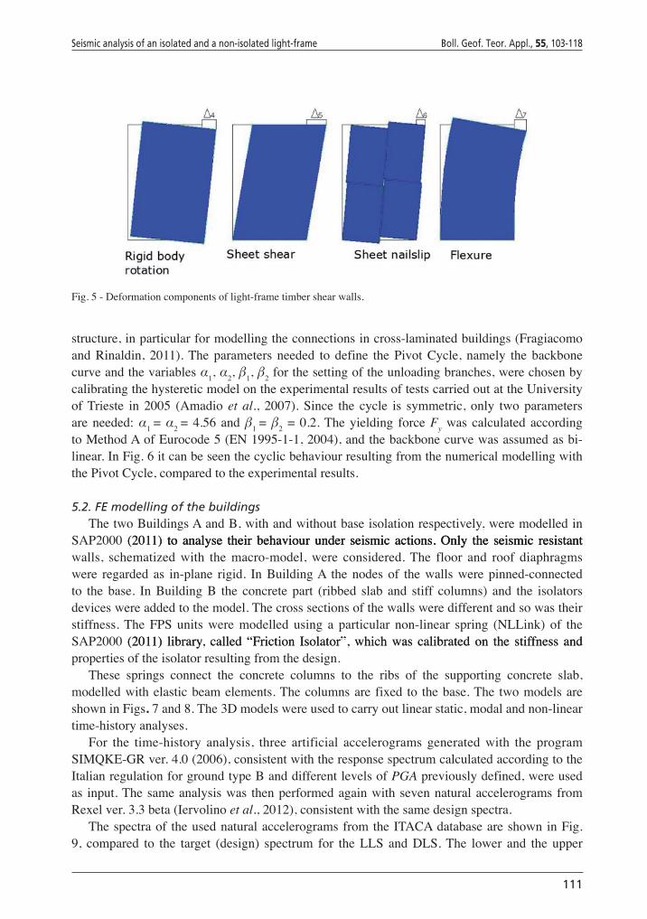
Δw=Δ4+Δ5+Δ6+Δ7. (6)
ThefourcomponentsofflexibilityaredisplayedinFig.5.SincetheFEmacro-modelwasusedtomodelthecyclicbehaviourofashearwallintime-
historyanalyses,the“Multi-linearplastic-PivotCycle”availableintheSAP2000(2011)librarywaschosentoschematizethehystereticbehaviourtypicallyobservedinlight-frameshearwalls.This relationship has been successfully employed in literature for another type of wooden
Seismic analysis of an isolated and a non-isolated light-frame Boll. Geof. Teor. Appl., 55, 103-118
111
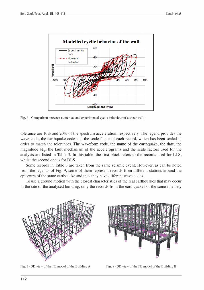
structure,inparticularformodellingtheconnectionsincross-laminatedbuildings(Fragiacomoand Rinaldin, 2011).The parameters needed to define the Pivot Cycle, namely the backbonecurveandthevariablesα1,α2,β1,β2forthesettingoftheunloadingbranches,werechosenbycalibratingthehystereticmodelontheexperimentalresultsoftestscarriedoutattheUniversityofTrieste in 2005 (Amadio et al., 2007). Since the cycle is symmetric, only two parametersareneeded:α1 =α2 =4.56 andβ1 =β2=0.2.Theyielding forceFywas calculated accordingtoMethodAofEurocode5(EN1995-1-1,2004),andthebackbonecurvewasassumedasbi-linear.InFig.6itcanbeseenthecyclicbehaviourresultingfromthenumericalmodellingwiththePivotCycle,comparedtotheexperimentalresults.
5.2. FE modelling of the buildingsThetwoBuildingsAandB,withandwithoutbaseisolationrespectively,weremodelledin
SAP2000 (2011) to analyse their behaviour under seismic actions. Only the seismic resistant(2011) to analyse their behaviour under seismic actions. Only the seismic resistant to analyse their behaviour under seismic actions. Only the seismic resistantwalls, schematized with the macro-model, were considered.The floor and roof diaphragmswere regarded as in-plane rigid. InBuildingA thenodesof thewallswerepinned-connectedto the base. In Building B the concrete part (ribbed slab and stiff columns) and the isolatorsdeviceswereaddedtothemodel.Thecrosssectionsofthewallsweredifferentandsowastheirstiffness.The FPS units were modelled using a particular non-linear spring (NLLink) of theSAP2000 (2011) library, called “Friction Isolator”, which was calibrated on the stiffness and(2011) library, called “Friction Isolator”, which was calibrated on the stiffness andpropertiesoftheisolatorresultingfromthedesign.
These springs connect the concrete columns to the ribs of the supporting concrete slab,modelledwithelasticbeamelements.Thecolumnsare fixed to thebase.The twomodelsareshowninFigs.7and8.The3Dmodelswereusedtocarryoutlinearstatic,modalandnon-lineartime-historyanalyses.
For the time-history analysis, three artificial accelerograms generated with the programSIMQKE-GRver.4.0(2006),consistentwiththeresponsespectrumcalculatedaccordingtotheItalianregulationforgroundtypeBanddifferentlevelsofPGApreviouslydefined,wereusedas input.Thesameanalysiswas thenperformedagainwithsevennaturalaccelerogramsfromRexelver.3.3beta(Iervolinoet al.,2012),consistentwiththesamedesignspectra.
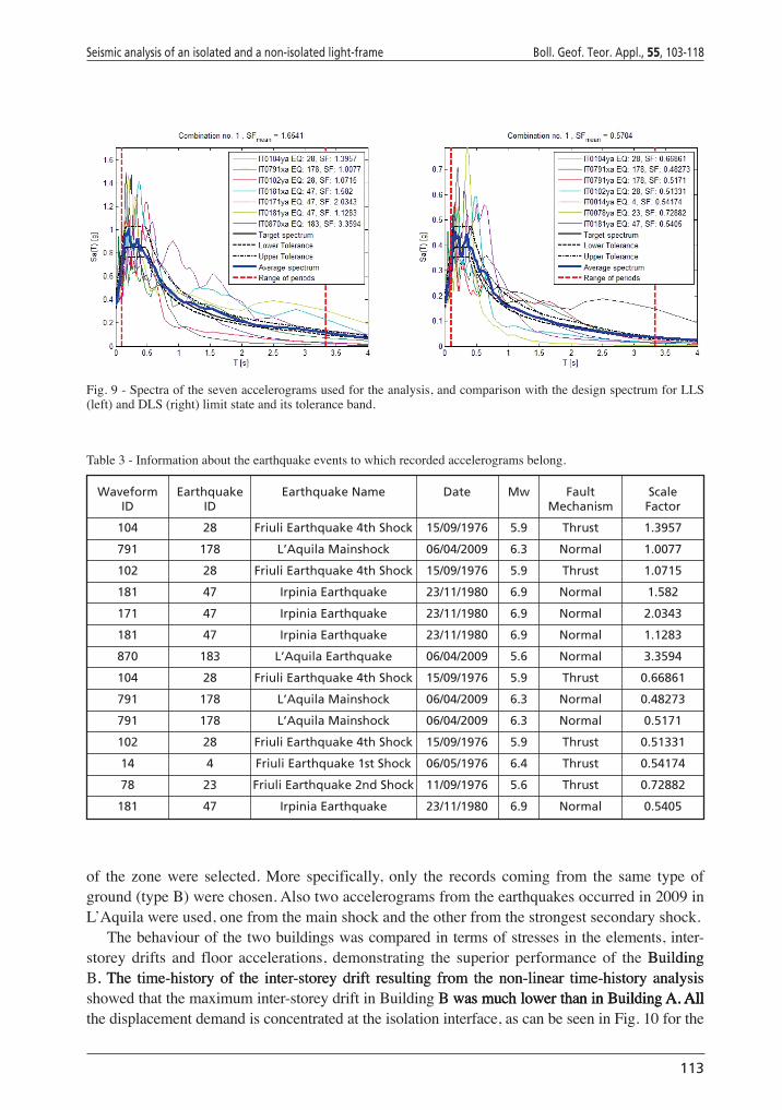
Thespectraof theusednaturalaccelerogramsfromtheITACAdatabaseareshowninFig.9, compared to the target (design) spectrum for the LLS and DLS.The lower and the upper
Fig.5-Deformationcomponentsoflight-frametimbershearwalls.
112
Boll. Geof. Teor. Appl., 55, 103-118 Sancin et al.
toleranceare10%and20%ofthespectrumacceleration,respectively.Thelegendprovidesthewavecode, theearthquakecodeandthescalefactorofeachrecord,whichhasbeenscaledinorder tomatch the tolerances.The waveform code, the name of the earthquake, the date, theThewaveformcode, thenameof the earthquake, thedate, themagnitude MW, the fault mechanism of the accelerograms and the scale factors used for theanalysis are listed inTable3. In this table, the firstblock refers to the recordsused forLLS,whilstthesecondoneisforDLS.
SomerecordsinTable3aretakenfromthesameseismicevent.However,ascanbenotedfromthe legendsofFig.9, someof themrepresent records fromdifferentstationsaround theepicentreofthesameearthquakeandthustheyhavedifferentwavecodes.
Touseagroundmotionwiththeclosestcharacteristicsoftherealearthquakesthatmayoccurinthesiteoftheanalysedbuilding,onlytherecordsfromtheearthquakesofthesameintensity
Fig.7-3DviewoftheFEmodeloftheBuildingA. Fig.8-3DviewoftheFEmodeloftheBuildingB.
Fig.6-Comparisonbetweennumericalandexperimentalcyclicbehaviourofashearwall.
Seismic analysis of an isolated and a non-isolated light-frame Boll. Geof. Teor. Appl., 55, 103-118
113
of the zonewere selected.More specifically, only the records coming from the same typeofground(typeB)werechosen.Alsotwoaccelerogramsfromtheearthquakesoccurredin2009inL’Aquilawereused,onefromthemainshockandtheotherfromthestrongestsecondaryshock.
Thebehaviourofthetwobuildingswascomparedintermsofstressesintheelements,inter-storey drifts and floor accelerations, demonstrating the superior performance of the BuildingBuildingB. The time-history of the inter-storey drift resulting from the non-linear time-history analysis.The time-historyof the inter-storeydrift resulting from thenon-linear time-history analysisshowedthatthemaximuminter-storeydriftinBuilding B was much lower than in Building A. AllB was much lower than in Building A. AllwasmuchlowerthaninBuilding A. AllA. All.Allthedisplacementdemandisconcentratedattheisolationinterface,ascanbeseeninFig.10forthe
Fig.9-Spectraofthesevenaccelerogramsusedfortheanalysis,andcomparisonwiththedesignspectrumforLLS(left)andDLS(right)limitstateanditstoleranceband.
Table3-Informationabouttheearthquakeeventstowhichrecordedaccelerogramsbelong.
Waveform Earthquake Earthquake Name Date Mw Fault Scale ID ID Mechanism Factor
104 28 Friuli Earthquake 4th Shock 15/09/1976 5.9 Thrust 1.3957
791 178 L’Aquila Mainshock 06/04/2009 6.3 Normal 1.0077
102 28 Friuli Earthquake 4th Shock 15/09/1976 5.9 Thrust 1.0715
181 47 Irpinia Earthquake 23/11/1980 6.9 Normal 1.582
171 47 Irpinia Earthquake 23/11/1980 6.9 Normal 2.0343
181 47 Irpinia Earthquake 23/11/1980 6.9 Normal 1.1283
870 183 L’Aquila Earthquake 06/04/2009 5.6 Normal 3.3594
104 28 Friuli Earthquake 4th Shock 15/09/1976 5.9 Thrust 0.66861
791 178 L’Aquila Mainshock 06/04/2009 6.3 Normal 0.48273
791 178 L’Aquila Mainshock 06/04/2009 6.3 Normal 0.5171
102 28 Friuli Earthquake 4th Shock 15/09/1976 5.9 Thrust 0.51331
14 4 Friuli Earthquake 1st Shock 06/05/1976 6.4 Thrust 0.54174
78 23 Friuli Earthquake 2nd Shock 11/09/1976 5.6 Thrust 0.72882
181 47 Irpinia Earthquake 23/11/1980 6.9 Normal 0.5405
114
Boll. Geof. Teor. Appl., 55, 103-118 Sancin et al.
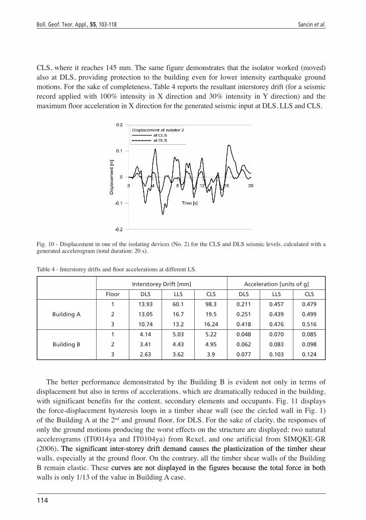
CLS,whereitreaches145mm.Thesamefiguredemonstratesthattheisolatorworked(moved)also at DLS, providing protection to the building even for lower intensity earthquake groundmotions.Forthesakeofcompleteness,Table4reportstheresultantinterstoreydrift(foraseismicrecord applied with 100% intensity in X direction and 30% intensity inY direction) and themaximumflooraccelerationinXdirectionforthegeneratedseismicinputatDLS,LLSandCLS.
Fig.10-Displacementinoneoftheisolatingdevices(No.2)fortheCLSandDLSseismiclevels,calculatedwithageneratedaccelerogram(totalduration:20s).
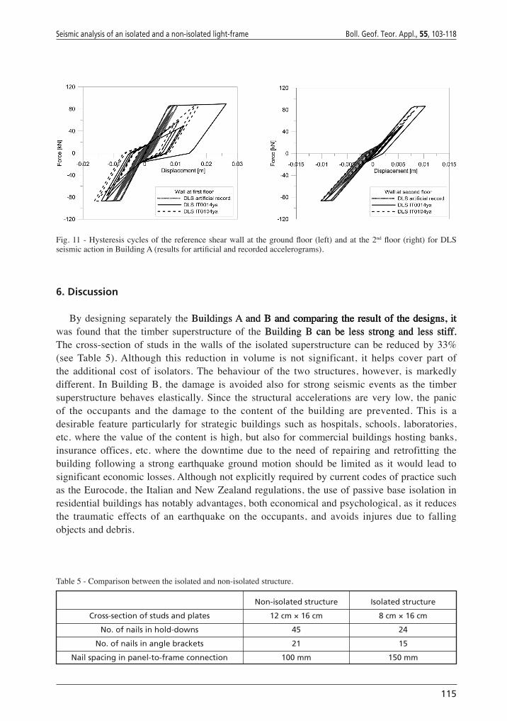
The better performance demonstrated by the Building B is evident not only in terms ofdisplacementbutalsointermsofaccelerations,whicharedramaticallyreducedinthebuilding,with significant benefits for the content, secondary elements and occupants. Fig. 11 displaysthe force-displacementhysteresis loops in a timber shearwall (see the circledwall inFig.1)oftheBuildingAatthe2ndandgroundfloor,forDLS.Forthesakeofclarity,theresponsesofonlythegroundmotionsproducingtheworsteffectsonthestructurearedisplayed:twonaturalaccelerograms (IT0014ya and IT0104ya) from Rexel, and one artificial from SIMQKE-GR(2006). The significant inter-storey drift demand causes the plasticization of the timber shear.The significant inter-storey drift demand causes the plasticization of the timber shearwalls,especiallyatthegroundfloor.Onthecontrary,allthetimbershearwallsoftheBuildingBremainelastic.These curves are not displayed in the figures because the total force in bothcurvesarenotdisplayed in thefiguresbecause the total force inbothwallsisonly1/13ofthevalueinBuildingAcase.
Table 4 - Interstorey drifts and floor accelerations at different LS.
Interstorey Drift [mm] Acceleration [units of g]
Floor DLS LLS CLS DLS LLS CLS
1 13.93 60.1 98.3 0.211 0.457 0.479
Building A 2 13.05 16.7 19.5 0.251 0.439 0.499
3 10.74 13.2 16.24 0.418 0.476 0.516
1 4.14 5.03 5.22 0.048 0.070 0.085
Building B 2 3.41 4.43 4.95 0.062 0.083 0.098
3 2.63 3.62 3.9 0.077 0.103 0.124
Seismic analysis of an isolated and a non-isolated light-frame Boll. Geof. Teor. Appl., 55, 103-118
115
6. Discussion
BydesigningseparatelytheBuildings A and B and comparing the result of the designs, itBuildingsA and B and comparing the result of the designs, itand B and comparing the result of the designs, itB and comparing the result of the designs, itandcomparingtheresultofthedesigns, itwas found that the timber superstructure of the Building B can be less strong and less stiff.Building B can be less strong and less stiff. can be less strong and less stiff.Thecross-sectionof studs in thewallsof the isolatedsuperstructurecanbe reducedby33%(see Table 5).Although this reduction in volume is not significant, it helps cover part ofthe additional cost of isolators.The behaviour of the two structures, however, is markedlydifferent. In Building B, the damage is avoided also for strong seismic events as the timbersuperstructure behaves elastically. Since the structural accelerations are very low, the panicof the occupants and the damage to the content of the building are prevented. This is adesirable feature particularly for strategic buildings such as hospitals, schools, laboratories,etc.where thevalueof thecontent ishigh,butalso forcommercialbuildingshostingbanks,insurance offices, etc. where the downtime due to the need of repairing and retrofitting thebuilding following a strong earthquake ground motion should be limited as it would lead tosignificanteconomiclosses.AlthoughnotexplicitlyrequiredbycurrentcodesofpracticesuchastheEurocode,theItalianandNewZealandregulations,theuseofpassivebaseisolationinresidentialbuildingshasnotablyadvantages,botheconomicalandpsychological,asitreducesthe traumatic effects of an earthquake on the occupants, and avoids injures due to fallingobjectsanddebris.
Fig. 11 - Hysteresis cycles of the reference shear wall at the ground floor (left) and at the 2nd floor (right) for DLS seismic action in Building A (results for artificial and recorded accelerograms).
Table5-Comparisonbetweentheisolatedandnon-isolatedstructure.
Non-isolated structure Isolated structure
Cross-section of studs and plates 12 cm × 16 cm 8 cm × 16 cm
No. of nails in hold-downs 45 24
No. of nails in angle brackets 21 15
Nail spacing in panel-to-frame connection 100 mm 150 mm
116
Boll. Geof. Teor. Appl., 55, 103-118 Sancin et al.
Table6-CostcomparisonbetweentheBuildingsAandB.
Description Building A Building B
Wooden structure and finishes including labour cost € 745 467 € 702 336
Concrete structure and finishes including labour cost € 399 802 € 425 652
Installations € 216 578 € 216 578
Windows and doors € 102 024 € 102 024
Isolators n.a. € 28 320
TOTAL € 1 463 871 € 1 474 910
8. Conclusions
Timber buildings are widely used around the world.They are a sustainable constructionsystemand,ifwelldesignedandbuilt,theyaresuitableforseismic-proneareasduetotheirlowmass.As wood structures are becoming more common also in countries with seismic hazardsuchasItaly,itisimportanttounderstandtheirseismicbehaviouranddesignthemtoprevent,orlimit,thedamage.
In this paper the case study of a 3-storey light-frame timber building was investigated.Light-frame timber construction systems have a high dissipative capacity [a behaviour factorup to5 is suggestedbyEurocode8 (EN 1998-1, 2005)��, due to the many nailed connectionsEN1998-1,2005)��, due to the many nailed connections)��, due to themanynailedconnectionsbetweenplywoodorothertypeofsheathingandthelighttimberframes.Thismeansthatduringahigh intensityearthquake thestructure is safe,butundergoessignificantdamage.Thepaperinvestigatesthepossibilityofusingpassivebaseisolationforpreventingthisdamage.
Athree-storeylight-framebuildingwasfirstdesignedwithoutandthenwithaseismicbaseisolationobtainedusingFrictionPendulumsIsolators.ThetwobuildingsweremodelledusingthecommercialFEprogramSAP2000(2011) and then three seismic analyses were performed:(2011)and then three seismic analyses were performed:andthenthreeseismicanalyseswereperformed:alinearstatic,amodalandanon-lineartimehistoryanalysiswithbothartificialandrecorded
7. Costs comparison
In this section, a brief evaluation of the total cost for both structures (isolated and non-isolated) is presented.All costs are calculated starting from the prices provided by producersandmanufacturers.Thecostshavebeencalculatedassumingthatbothbuildingshavethesamebasement.
Themaindifferences inTable6arerepresentedbythestructuralmaterialcostsandbythecost of isolators.The cost of the concrete columns and slab supporting the timber structureincluding the finishes is considered in both the BuildingsA and B. In Building B the totalvolumeofthetimberstructureislessthaninBuildingA,butmoreconcretehastobeusedtostrengthen the ribbedRCslab supporting the timber superstructureabove the isolators. In theend,however, the totalcostof the twobuildingsdiffersbyonly0.75%,whichmakes theuseof passive base isolation for light-frame construction very attractive considered the superiorperformanceoftheBuildingB.
Seismic analysis of an isolated and a non-isolated light-frame Boll. Geof. Teor. Appl., 55, 103-118
117
accelerograms.Aresearchwasundertakentofindthemostsuitableschematizationofthelight-frame shear-walls, as they are the elements that govern the seismic behaviour of the entirebuilding.Theparametersformodellingtheshear-wallswerecalculatedbasedonprescriptionsfromEurocode5(EN 1995-1-1, 2004) and New Zealand Timber Standard.(EN1995-1-1,2004)and New Zealand Timber Standard.andNewZealandTimberStandard.
BoththeBuildings A and B were in-line with the seismic requirements of current regulations.BuildingsAandB were in-line with the seismic requirements of current regulations.werein-linewiththeseismicrequirementsofcurrentregulations.Despitethis,duringthedesignearthquaketheBuilding A undergoes high damage, especially atBuildingA undergoes high damage, especially atundergoeshighdamage,especiallyatthe ground floor, which is designed to dissipate the seismic energy. Conversely, the isolatedstructureremainselastic.Thewholedisplacementisconcentratedintheisolationunits,whichdramatically reduce theaccelerations in the superstructureandsatisfy the requirementsof theDAD.
Asthetimbersuperstructureisverylightcomparedtotheverticalcapacityoftheisolators,thesystemisoptimizedifthetimbersuperstructureishigherthantwostoreysandhasasmallerareainplan.Forthecasestudybuildinganalysedinthispaper,where16isolatorswereused,it was calculated that the cost difference with the Building A is only 11,��� �, correspondingBuilding A is only 11,��� �, corresponding is only 11,��� �, corresponding to0.75%ofthetotalcostofBuilding A. The factors that influence this difference are three: theBuildingA. The factors that influence this difference are three: the.Thefactorsthatinfluencethisdifferencearethree:thesavinginwoodmaterialfortheisolatedstructure;thehighercostoftheconcretebasementfortheisolatedstructure;andthecostoftheisolatingunits.Theadditionalcostoftheisolationisbyfarcounterbalancedbytheincreasedsafetyofthebuilding.Therefore,passivebaseisolationshould be considered more often when designing light-frame timber buildings in earthquake-prone areas. Passive base isolation not only makes the buildings safer, but also dramaticallyimproves the seismic performance of the structure during the earthquake, and consequentlyreduces fear of the occupants. However, particular care in reducing the cross sections of thestructural elements has to be taken in Building B, in order to avoid excessive deformabilityBuilding B, in order to avoid excessive deformability, in order to avoid excessive deformabilityorvibrationsinthestructureduringthenormaluse.Inthiswork,alltheverificationsrequiredaccordingtoEurocode5(EN 1995-1-1, 2004) and 8 (EN 1998-1, 2005) and the Italian technical(EN1995-1-1,2004)and 8 (EN 1998-1, 2005) and the Italian technical8(EN 1998-1, 2005) and the Italian technicalEN1998-1,2005)and the Italian technicalandtheItaliantechnicalregulationforconstructionhavebeendoneandthestructureinBuilding B is not affected by thisB is not affected by thisisnotaffectedbythisproblem.Nevertheless,itshouldbeobservedthatpassivebaseisolationcanbeusedonlywhenthedesignisgovernedbyseismicactionsandnotbywindactions,whichisnotalwaysthecasefortimberbuildings.
Acknowledgements. ThesupportprovidedbytheSardiniaRegionthroughtheresearchgrant“Numerical-experimentalbehaviouroftimberpanelsunderin-planeandout-of-planeloading”isgratefullyacknowledged.TheGNGTSconferenceorganizersarealsoacknowledgedforthepossibilitytopresentthisresearch.
REFERENCES
AmadioC.,GattescoN.andUrbanF.;2007:Indagine sperimentale su pareti di controvento in legno realizzate con pannelli in OSB o in gesso rinforzato con fibre.In:Proc.XIIConvegnoANIDIS,L’ingegneriasismicainItalia,Pisa,Italy,pp.1-11,(inItalian).
BeattieG.,BuchananA.H.,GauntD.andSojaE.;2001:Multi-storey timber buildings manual.CarterHoltHarveyWoodProducts,FletcherChallengeForestsLtd,JamesHardieBuildingProductsInc.andWinstoneWallboardsLtd,Australia-NewZealand.
BradleyB.A.,DhakalR.P.,ManderJ.B.andLiL.;2008:Experimental multi-level seismic performance assessment of 3D RC frame designed for damage avoidance.EarthquakeEng.Struct.Dyn.,37,1-20.
118
Boll. Geof. Teor. Appl., 55, 103-118 Sancin et al.
ConstantinouM.C.;2004:Friction pendulum double concave bearing.TechnicalReport,UniversityatBuffalo,StateUniversityofNewYork,Buffalo,NY,USA,33pp.and2appendices.
EN 1995-1-1; 2004: Eurocode 5: design of timber structures - Part 1-1: general - common rules and rules for buildings. European Committee for Standardition (CEN), Bruxelles, Belgium, 123 pp. with EN 1995-1-1/AC:2006incorporated
EN1998-1;2005:Eurocode 8: design of structures for earthquake resistance - Part 1: general rules seismic actions and rules for buildings. EuropeanCommitteeforStandardition(CEN),Bruxelles,Belgium,215pp.
FenzD.M.andConstantinouM.C.;2006:Behaviour of the double concave friction pendulum bearing.EarthquakeEarthquakeEng.Struct.Dyn.,35,1403-1424.
FIP Industriale; 2010: Catalogue S04. Isolatori a scorrimento a superficie curva. Fip Group, Selvazzano Dentro, Fip Group, Selvazzano Dentro,Padova,Italy,15pp.,in Italian.inItalian.
FollesaM.,FragiacomoM.andLauriolaM.P.;2011:A proposal for revision of the current timber part (Section 8) of Eurocode 8 - Part 1.In:Proc.44thMeetingWorkingCommissionW18-TimberStructures,CIB,Int.CouncilRes.Innov.BuildingConstr.,Alghero,Italy,paperCIB-W18/44-15-1.
Fragiacomo M. and Rinaldin G.; 2011: Advanced models for seismic analyses of timber buildings. In:AußergewöhnlicheEinwirkung-Erdbeben-imHolzbau,Workshoponcrosslamconstruction“GrazerHolzbau-Fachtagung-9.GraFHT’11”,TechnicalUniversityofGraz,Austria,30pp.
Iervolino I., Galasso C. and Cosenza E.; 2012: REXEL: computer aided record selection for code-based seismic structural analysis.Bull.EarthquakeEng.,8,339-362.
Mander J.B. and Cheng C.T.; 1997:Seismic resistance of bridge piers based on damage avoidance design.Tech.reportNCEER-97-0014,U.S.Nat.CenterEarthquakeEng.Res. (NCEER),Dept.CivilEnviron.Eng.,Buffalo,NY,USA,144pp.
Mezzi M. and ParducciA.; 1998: Base isolation in retrofitting historic buildings. In: Proc. of Monument-98,WorkshoponSeismicPerformanceofMonuments,Lisboa,Portugal,pp.249-257.
NTC2008;2008:D.M. 14/01/2008 - Nuove norme tecniche per le costruzioni - NTC2008.ConsiglioSuperioredeiLavoriPubblici,Roma,Italy,inItalian.
NZS3603;1993:Timber structures standard.Wellington, New Zealand.Wellington,NewZealand.SAP2000; 2011: Integrated solution for structural analysis & design, vers. 14.0.0, structural analysis program.
ComputersandStructuresInc.,Berkeley,CA,U.S.A.SIMQKE-GR; 2006: Programma per la generazione di accelerogrammi artificiali spettro-compatibili vers. 4.04.0,
civil engineering free software. Università di Brescia, Italy, http://dicata.ing.unibs.it/gelfi/software/programmi_studenti.html.
Zayas V.A., Low S.S. and Mahin S.A.; 1990: A simple pendulum technique for achieving seismic isolation.EarthquakeSpectra,6,317-333.
Corresponding author: Ljuba Sancin Contemporary Building Design d.o.o. Sojerejeva ulica 3, 1000 Ljubljana, Slovenia Phone: +39 340 2741972; e-mail: [email protected]