Embed Size (px)
Citation preview

B750-00-880
Issue D
Manor Royal, Crawley, West Sussex, RH10 2LW, UK Telephone: +44(0)1293 528844 Fax: +44(0)1293 533453 http://www.bocedwards.com
Instruction Manual
Seiko Seiki STP-A2203 (P041) Turbomolecular Pump System (Document number MT-41E-002-A)
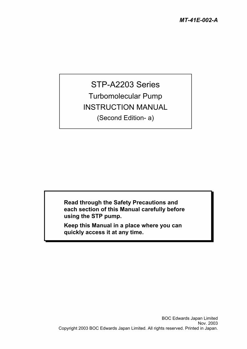
MT-41E-002-A
BOC Edwards Japan Limited Nov. 2003
Copyright 2003 BOC Edwards Japan Limited. All rights reserved. Printed in Japan.
STP-A2203 Series Turbomolecular Pump
INSTRUCTION MANUAL (Second Edition- a)
Read through the Safety Precautions and each section of this Manual carefully before using the STP pump. Keep this Manual in a place where you can quickly access it at any time.
STP-A2203 Series Instruction Manual
SAFETY PRECAUTIONS
The Safety Precautions in this Manual constitute guidelines to protect operators, the STP pump and its peripheral equipment. To avoid personal injury and prevent product and/or peripheral equipment damage, observe the Safety Precautions as well as the general safety rules (your country’s laws, regulations, safety standards and so on). If the equipment is used in a manner not specified by BOC Edwards, the protection provided by the equipment may be impaired.
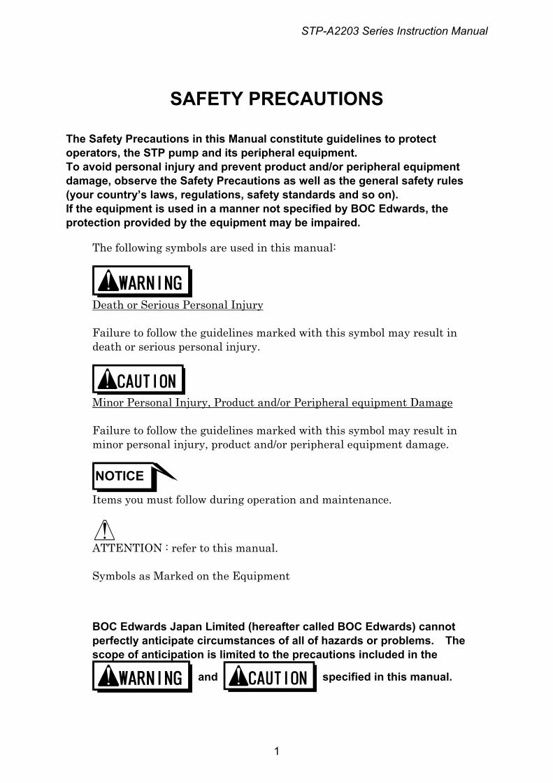
The following symbols are used in this manual:
Death or Serious Personal Injury Failure to follow the guidelines marked with this symbol may result in death or serious personal injury.
Minor Personal Injury, Product and/or Peripheral equipment Damage Failure to follow the guidelines marked with this symbol may result in minor personal injury, product and/or peripheral equipment damage.
NOTICE
Items you must follow during operation and maintenance.
ATTENTION : refer to this manual. Symbols as Marked on the Equipment
BOC Edwards Japan Limited (hereafter called BOC Edwards) cannot perfectly anticipate circumstances of all of hazards or problems. The scope of anticipation is limited to the precautions included in the
and specified in this manual.
1
STP-A2203 Series Instruction Manual
◇ The STP pump is provided with a high-speed rotor. Secure the STP pump according to the specified method. Failure to do so may lead to serious personal injury, product and/or peripheral equipment damage if any abnormality/error occurs in the rotor.
◇ The STP pump operates at high temperatures while the baking heater or the Temperature Management System (TMS) unit is in operation. NEVER touch the STP pump and its peripheral equipment while the baking heater or TMS unit is in operation. Operators can burn hands.
◇ Execute the following to prevent an accident caused by the gas. • Check the properties of the gas to be used, referring to the
Material Safety Data Sheet (MSDS) you obtain from the gas supplier. (explosive・combustible・toxic・corrosive, etc) And, keep MSDS and a safety advice of gas supplier.
• Warn of the danger of the gas with the warning label when the use gas is hazardous chemical materials.
• Always execute gas purge in the pump with the inert gas, and then exhaust residual gases thoroughly from the STP pump when removing the STP pump from the vacuum equipment.
• Secure safety by wearing personal protective equipment when using the gas which might influence damage health. In addition, take appropriate measure for depending upon the properties of the gas to be used.
◇ Exhaust residual gas thoroughly when disposing of the STP pump. If the STP pump is used for any toxic or reactive gas, always clean the STP pump and dispose of it as industrial waste in accordance with guidelines given by the national and/or local government. Residual gas in the STP pump may cause an accident which, for certain gases, may involve serious injury or death.
2
STP-A2203 Series Instruction Manual
◇ NEVER use any gas that is not specified as usable in this Manual. The use of such gas may corrode the STP pump and damage it.
◇ A hazardous live voltage may exist at connector that marked . DO NOT touch the terminal. Doing so may result in electric shock. When operating connection/disconnection to connector, always power OFF the STP pump (Switch the breaker "OFF").
◇ Always check the STP pump has stopped, then turn OFF the primary power (switch the breaker "OFF") before proceeding to any of the following operations. Failure to do so may cause the STP pump to rotate accidentally, which may injure operators seriously or result in electric shock. Moreover, do not remove the connecter while the pump is rotating. The voltage might be output to connector according to the rotational speed, and it causes the electric shock or the failure. • Connect or disconnect cables; • Perform maintenance such as replacement of fuses; • Perform inspections such as deposit and/or the air cooling fan; or • Perform investigations into probable causes and action/measures
taken in the event of occurrence of a problem. ◇ Do not perform the insulation test (insulation resistance test and
withstand voltage test) to the STP control unit and STP pump. When performing the insulation test to your equipment, turn "OFF" the STP control unit. The varistor for the power supply line protection is installed to the STP control unit. DO NOT perform the insulation test with the varistor installed. Doing so may result in product damage.
◇ When "emergency off" (EMO) circuit is installed in the vacuum equipment, consider the following to stop the STP pump safely when the EMO circuit operates. • When the EMO circuit operates, atmosphere might be introduced
in the STP pump depending upon the backing pump. Unite the exhaust gas system to prevent atmosphere from being introduced into the STP pump when the EMO circuit operates. (example: shut the valve) When atmosphere is introduced into the STP pump, the touch down bearing may not operate normally.
3
STP-A2203 Series Instruction Manual
◇ When removing or installing the pump or at maintenance and inspection, follow the precautions below. Failure to do so might hurt your back or cause injuries due to occurrence of an accident such as fall. • Use a crane or the like when lifting the heavy product of 18kg or
more. • When lifting by hands for unavoidable reason, two or more people
must always conduct it. • When lifting STP control unit with handles, support bottom of STP
control unit, do not have only handle. ◇ Install the STP control unit not only by fitting it with the front panel
fitting screws but also by supporting it from the bottom side. Fitting the STP control unit with the screws only cannot sustain its weight, and therefore resulting in product damage.
◇ Always use the STP pump and STP control unit with same model name, which are specified on their own nameplate. If you plan to use the units having different model names, an error massage is indicated and they may not be used. In the latter case, contact our Service office. If you plan to use the units having the same model name but different serial numbers, an error message is indicated when they are used without tuning. And, the tuning is necessary when the length of the STP connection cable is changed. They may not function normally when they are used without tuning. Once tuning is completed, re-tuning is not required unless the configuration (the STP pump serial number, the STP control unit serial number, and the STP connection cable length) is changed.
◇ Use the STP connection cable that BOC Edwards has specified. The use of different cables may result in product damage.
◇ Connect the cables securely. NEVER bend nor place heavy objects on the cable. Doing so may result in electric shock or product damage.
◇ NEVER remove the splinter shield from the STP pump. Doing so may result in product damage.
◇ DO NOT put foreign objects into the STP pump. Doing so may result in product damage.
◇ Always use the power voltage specified on the nameplate for the primary power voltage of the STP control unit. Wire the power cable securely. Incorrect wiring may result in electric shock or product damage.
◇ The wipes used for clean the flange of the pump might become hazardous waste depending upon the solvent (alcohol). Dispose of the contaminated wipes appropriately according to the regulations of each national and/or local government.
4
STP-A2203 Series Instruction Manual
◇ NEVER turn OFF the primary power (DO NOT switch the breaker "OFF") while the STP pump is rotating. Doing so may result in product damage.
◇ Perform investigations into probable causes and remove them before restarting the STP pump in the event of the occurrence of a problem. The use of the abnormal STP pump may result in product damage.
◇ DO NOT move the STP pump and the STP control unit while the STP pump is in operation. Doing so may result in product damage.
5
STP-A2203 Series Instruction Manual
INTRODUCTION
Thank you very much for purchasing BOC Edwards’ turbomolecular pump. The turbomolecular pump is designed to be installed in the vacuum equipment to exhaust gases from it. This manual covers all items necessary to ensure safe installation, operation and maintenance of the following series of the STP-A2203 turbomolecular pump:
Model Name Specification
• STP-A2203C High-throughput type, chemical specific *1 • STP-A2203CV High-throughput type, chemical specific, TMS unit*2 attached
For the specifications of other models of the STP-A2203 pump series, contact BOC Edwards.
The above STP-A2203 pump series is collectively referred to as the "STP pump."
*1 : Chemical specific: STP pump with anti-corrosive treatment
(responding to chlorine, fluorine or other system gases) *2 : TMS: Temperature Management System
6
STP-A2203 Series Instruction Manual
APPLIED STANDARDS
The STP pump conforms to the following directives and standards:
◇ Applied Directives
・ EC Machinery Directive ・ EC Electromagnetic Compatibility Directive ・ EC Low Voltage Directive
◇ Applied Standards
・ EN1012-2 ・ EN61010-1 ・ EN55011 (class A) ・ EN61000-6-2
◇ Applied Standards (Only a some model)*1
・ UL3101-1, 1993 (Electrical Equipment for Laboratory Use; Part 1 : General Requirements)
PRECAUTIONS
1) No part of this manual may be reproduced in any form by any means without prior written permission from BOC Edwards.
2) BOC Edwards pursues a policy of continuing improvement in design and performance of this product. The right is, therefore, reserved to vary specifications and design without notice. Understand that the product you purchased and its contents including specifications described in this manual may differ.
REQUEST
If you find inaccuracies or errors in this manual, advise distributor or the nearest Service office.
*1 : Contact BOC Edwards about recognized model.
7
STP-A2203 Series Instruction Manual
LIMITED WARRANTY
This WARRANTY applies to the customer to whom BOC Edwards has delivered this product.
1. WARRANTY PERIOD: BOC Edwards warrants this product against defects for a period of two (2) years from the date of delivery or during the period specified in the agreement made by and between the customer and BOC Edwards.
2. ITEM WARRANTED: 1) This warranty applies only to the product delivered from BOC Edwards
to the customer. 2) If any defect is found during this period, BOC Edwards will, at its option,
repair or recondition the product free of charge. The costs for repair or replacement of the product after the warranty period has passed will be at your own charge.
3. DISCLAIMER: BOC Edwards makes no warranty with respect to any damage occurred due to any of the following during the warranty period: 1) Handling, operation or maintenance other than that specified herein; 2) Failure to follow any of the warnings or cautions enumerated under
or ; 3) Installation, operation or maintenance using parts which are not
specified by BOC Edwards; 4) Maintenance personnel other than those authorized by BOC
Edwards or Service office have disassembled, reconditioned, or tampered the product;
5) Defect resulting from the not-specified use of the product. 6) When the product is used under special conditions without
obtaining the written consent of BOC Edwards (Particular gases, strong magnetic field and the radiation are added to the product.);
7) Defect resulting from deposit; 8) Water cooling system defect resulting from water quality used; 9) Defect resulting from the installation of the product (Exclude the
installation by authorized personnel.) 10) Deterioration in the external because of use (Discoloration,
scratches and so forth)
8
STP-A2203 Series Instruction Manual
9
11) Product damage occurred during transport or other factors not
attributable to BOC Edwards; 12) Product breakage or damage due to natural disasters, fire or other
external factors; 13) Deterioration in the basic performance due to the use of the product
beyond limits of the use; 14) Any direct, incidental or consequential damage resulting from the
use of the product; 15) When continuously operated without overhaul after the WARNING
indication ("WARNING" message) on the LCD display; 16) Overhaul and replacement of maintenance parts;
4. SPARE PARTS: ● Fuse and air cooling fan for control unit ● Touch down bearing ● Heater
STP-A2203 Series Instruction Manual
TABLE OF CONTENTS
SAFETY PRECAUTION INTRODUCTION PRECAUTIONS REQUEST LIMITED WARRANTY 1 Precautions for Safe Operation of the STP Pump.............................................. 1-1
1.1 Usable Gases...................................................................................................................... 1-1 1.2 Maintenance and Inspection Precautions........................................................................... 1-1 1.3 Labels.................................................................................................................................. 1-1
2 Operation Principle of the STP Pump................................................................. 2-1 3 Unpacking .......................................................................................................... 3-1
3.1 Unpacking the STP Pump and the STP Control Unit ......................................................... 3-1 3.2 Accessories......................................................................................................................... 3-2
4 Installation of the STP Pump.............................................................................. 4-1 4.1 Name and Function of Each Part........................................................................................ 4-1 4.2 Precautions Before Installation ........................................................................................... 4-3
4.2.1 Operating Environment .......................................................................................... 4-3 4.2.2 Installation Area ..................................................................................................... 4-4 4.2.3 Bench ..................................................................................................................... 4-4
4.3 How to Install the STP Pump .............................................................................................. 4-6 4.3.1 Cleaning the Seal................................................................................................... 4-7 4.3.2 STP Pump Installation Positions............................................................................ 4-8 4.3.3 How to Secure the STP Pump............................................................................... 4-9 4.3.4 Vacuum Piping ..................................................................................................... 4-13 4.3.5 Connecting the Purge Port................................................................................... 4-15 4.3.6 Connecting the Cooling Water Valve (For use with TMS unit only) .................... 4-16
5 Gas Suction, Cooling and Baking the STP Pump .............................................. 5-1 5.1 Gas Suction......................................................................................................................... 5-1
5.1.1 How to Introduce a Purge Gas............................................................................... 5-1 5.2 Cooling the STP Pump........................................................................................................ 5-2
5.2.1 Water Cooling Method ........................................................................................... 5-2 5.3 Baking the STP Pump......................................................................................................... 5-3
5.3.1 Attaching a Baking Heater ..................................................................................... 5-3
6 Installation of the STP Control Unit .................................................................... 6-1 6.1 Name and Function of Each Part........................................................................................ 6-1
6.1.1 Front Panel............................................................................................................. 6-1 6.1.2 Rear Panel ............................................................................................................. 6-4
6.2 Precautions Before Installation ........................................................................................... 6-5 6.2.1 Operating Environment .......................................................................................... 6-5 6.2.2 Insulation Test........................................................................................................ 6-5 6.2.3 Installation Area ..................................................................................................... 6-6
6.3 Attaching the STP Control Unit to a Rack........................................................................... 6-7 6.4 Cable Connection................................................................................................................ 6-8
6.4.1 Name and Dimensions of Each Cable................................................................... 6-8 6.4.2 How to Connect the Cables ................................................................................... 6-9
10
STP-A2203 Series Instruction Manual
6.5 Connecting to Semiconductor Equipment ........................................................................ 6-11 6.5.1 Connecting to Power............................................................................................ 6-11 6.5.2 Emergency Off Circuit (EMO Circuit) ................................................................... 6-11
7 How to Start/Stop the STP Pump....................................................................... 7-1 7.1 Before Starting .................................................................................................................... 7-1 7.2 Start Procedures ................................................................................................................. 7-2 7.3 Stop Procedures ................................................................................................................. 7-2 7.4 Manual Operation................................................................................................................ 7-3
7.4.1 Powering ON.......................................................................................................... 7-3 7.4.2 Starting the STP Pump .......................................................................................... 7-3 7.4.3 Stopping the STP Pump ........................................................................................ 7-4 7.4.4 Starting the STP Pump after Stopping................................................................... 7-4 7.4.5 Powering OFF........................................................................................................ 7-4 7.4.6 Starting the STP Pump after a Safety Function Operates..................................... 7-4
7.5 Remote Operation............................................................................................................... 7-5 7.5.1 Powering ON.......................................................................................................... 7-5 7.5.2 Starting/Stopping the STP Pump........................................................................... 7-5 7.5.3 Starting the STP Pump after Stopping................................................................... 7-6 7.5.4 Powering OFF........................................................................................................ 7-6 7.5.5 Starting the STP Pump after a Safety Function Operates..................................... 7-6
7.6 Operating the TMS Unit (For use with the TMS unit only) .................................................. 7-7 7.6.1 Starting/Stoping...................................................................................................... 7-7 7.6.2 Temperature Control .............................................................................................. 7-7
8 Remote Input/Output Signal Connector.............................................................. 8-1 8.1 Input Signal Pins ................................................................................................................. 8-1 8.2 Output Signal Pins .............................................................................................................. 8-4
9 Adjustment Methods .......................................................................................... 9-1 9.1 Tuning ................................................................................................................................. 9-1
9.1.1 Tuning Method ....................................................................................................... 9-1 9.1.2 Each of data after tuning........................................................................................ 9-2
9.2 Confirmation Mode.............................................................................................................. 9-4 9.3 Parameter Set Mode........................................................................................................... 9-6
10 Safety Functions .............................................................................................. 10-1 10.1 Power Failure .................................................................................................................... 10-1 10.2 Abnormal State of Magnetic Bearing ................................................................................ 10-3 10.3 Excessive Vibration........................................................................................................... 10-3 10.4 Motor Driver Overload....................................................................................................... 10-3 10.5 Overheating Inside the STP Pump ................................................................................... 10-3 10.6 Overheating Inside the STP Control Unit.......................................................................... 10-4 10.7 Overspeed......................................................................................................................... 10-4 10.8 Abnormality/Error in the TMS Unit (for Use with the TMS Unit) ....................................... 10-4
11 Troubleshooting, Maintenance, and Inspection................................................ 11-1 11.1 Troubleshooting Immediately after an Abnormality/Error Occurs..................................... 11-1
11.1.1 Troubleshooting Power Failure............................................................................ 11-1 11.1.2 Troubleshooting Other Abnormality/Error ............................................................ 11-1
11.2 When Error Message is Displayed on LCD ...................................................................... 11-2 11.2.1 Error Messages.................................................................................................... 11-2
11.3 Other Abnormalities .......................................................................................................... 11-8 11.3.1 Abnormalities When Powering ON ...................................................................... 11-8 11.3.2 Abnormalities When Performing the STP Pump Start Operation ........................ 11-8 11.3.3 Other Abnormalities ............................................................................................. 11-9
11.4 "WARNING" Message Display Function......................................................................... 11-10 11.4.1 First Damage Limit ............................................................................................. 11-10 11.4.2 Second Damage Limit........................................................................................ 11-11 11.4.3 CAUTION X_H, Y_H, X_B, Y_B, Z .................................................................... 11-11
11.5 "ERROR RECORD" Message Display Function ............................................................ 11-11
11
STP-A2203 Series Instruction Manual
11.6 Maintenance and Inspection ........................................................................................... 11-12 11.6.1 Cleaning and Decontamination.......................................................................... 11-13 11.6.2 Inspecting the Deposit ....................................................................................... 11-14 11.6.3 Overhaul............................................................................................................. 11-15 11.6.4 Transporting for Repair or Overhaul .................................................................. 11-16
12 Storage and Disposal ....................................................................................... 12-1 12.1 Storage of the STP Pump ................................................................................................. 12-1 12.2 Storage of the STP Control Unit ....................................................................................... 12-1 12.3 Disposal ............................................................................................................................ 12-2
13 Specifications ................................................................................................... 13-1 13.1 Specifications for the STP Pump ...................................................................................... 13-1 13.2 Specifications for the STP Control Unit............................................................................. 13-5
UNIT CONVERSION TABLE
ANNEX
MALFUNCTION INFORMATION STP Series / Global Service Network
12
STP-A2203 Series Instruction Manual
TABLES
Table 3.1 Accessories ................................................................................................................... 3-2 Table 3.2 Optional Accessories .................................................................................................... 3-2 Table 4.1 Tightening torque of bolt ................................................................................................. 4-9 Table 4.2 Maximum Torque predicted and Recommended securing bolt for inlet port flange..... 4-10 Table 4.3 Number of Claw Clamps by Size of Flange.................................................................. 4-11 Table 6.1 Connecting the Power Cable........................................................................................ 6-10 Table 7.1 Starting/Stopping the STP Pump during Remote Operation (REMOTE X7) ................ 7-5 Table 7.2 Reset Operation during Remote Operation (REMOTE X7) .......................................... 7-6 Table 8.1 REMOTE X7 Input Signal Pins....................................................................................... 8-2 Table 8.2 REMOTE X7 Output Signal Pins .................................................................................... 8-4 Table 8.3 Rated Contacts for Relays CR1 to CR8 ......................................................................... 8-7 Table 9.1 Data List.......................................................................................................................... 9-2 Table 10.1 States of Lamps and REMOTE Output Signals at a Power Failure ........................... 10-2 Table 10.2 Operations of the STP Pump after a Power Recovery ............................................... 10-2 Table 10.3 Safety Functions ......................................................................................................... 10-6 Table 10.4 Safety Functions (When the TMS Unit is Used) ......................................................... 10-8 Table 11.1 Error Messages ............................................................................................................ 11-3 Table 11.2 Troubleshooting after Powering ON ............................................................................. 11-8 Table 11.3 Troubleshooting When Performing the STP Pump Start Operation............................. 11-8 Table 11.4 Troubleshooting While the STP Pump Is Rotating ....................................................... 11-9 Table 11.5 Cleaning and Decontamination .................................................................................. 11-13 Table 13.1 Specifications for the STP Pump.................................................................................. 13-1 Table 13.2 Specifications for the STP Control Unit ........................................................................ 13-5
13
STP-A2203 Series Instruction Manual
14
FIGURES
Figure 2.1 Cross Sectional View of the STP Pump ....................................................................... 2-2 Figure 3.1 Example of Lifting the STP Pump ................................................................................. 3-2 Figure 4.1 Configuration of the STP Pump...................................................................................... 4-2 Figure 4.2 Installation of the STP Pump to the Vacuum Equipment ............................................... 4-6 Figure 4.3 STP Pump Installation Positions .................................................................................... 4-8 Figure 4.4 Positions of the Outlet Port on the Horizontally or Slanted Installed STP Pump ........... 4-8 Figure 4.5 Example of securing the STP pump (When securing the inlet port with bolts).......... 4-10 Figure 4.6 Shape of Reduced Diameter Shank Bolts .................................................................... 4-11 Figure 4.7 Example of securing the STP pump (When securing the inlet port flange with claw clamps) ............................................... 4-12 Figure 4.8 Example of securing the STP pump (When installing the damper in the inlet port flange) .................................................... 4-12 Figure 4.9 Connecting the Purge Port ........................................................................................... 4-15 Figure 4.10 External Dimensions of Cooling Water Valve............................................................... 4-17 Figure 4.11 Piping of Cooling Water Valve...................................................................................... 4-18 Figure 5.1 Attaching Positions of the Cooling Unit and Baking Heater ......................................... 5-4 Figure 6.1 STP Control Unit Front Panel ......................................................................................... 6-3 Figure 6.2 STP Control Unit Rear Panel.......................................................................................... 6-4 Figure 6.3 Peripheral Space of the STP Control Unit ...................................................................... 6-6 Figure 6.4 Example of Securing the STP Control Unit .................................................................... 6-7 Figure 6.5 External Dimensions of Each Cable ............................................................................... 6-8 Figure 7.1 STP Pump Operation Procedures ................................................................................ 7-8 Figure 8.1 REMOTE X7 Input Signal Pins....................................................................................... 8-3 Figure 8.2 REMOTE X7 Output Signal Pins .................................................................................... 8-6 Figure 9.1 Tuning Procedures ......................................................................................................... 9-3 Figure 9.2 Confirmation Mode Operation Method ........................................................................... 9-5 Figure 9.3 Parameter Setting Method.............................................................................................. 9-7 Figure 9.4 Remote Mode Setting Method........................................................................................ 9-8 Figure 13.1 External Appearance of the STP Pump........................................................................ 13-2 Figure 13.2 TMS Unit Assembly Drawing........................................................................................ 13-3 Figure 13.3 Label Affixing Positions for the STP Pump................................................................... 13-4 Figure 13.4 External Appearance of the STP Control Unit .............................................................. 13-6 Figure 13.5 Label Affixing Positions for the STP Control Unit ......................................................... 13-7
STP-A2203 Series Instruction Manual
1 Precautions for Safe Operation of the STP Pump
Inst
alla
tion 1.1 Usable Gases
The STP series models are chemical specific pumps: chlorine or fluorine system gases can be used. When you use gases including alkaline metals, but excluding Li, gases including Ga, Hg, In, or Sn, or HBr, contact BOC Edwards.
◇ To prevent an accident, confirm the characteristics of gases to be
used, referring to the Material Safety Data Sheet (MSDS) you obtain from the gas supplier. And, keep MSDS and a safety advice of gas supplier.
◇ Introduce a dry N2 gas (purge gas) to protect the inside of the STP
pump when using reactive or corrosive. The use of reactive or corrosive gas may result in product damage.
◇ Cool the STP pump to prevent the STP pump from overheating when pumping gases.
1.2 Maintenance and Inspection Precautions
Perform any maintenance or inspection of the STP pump and the STP control unit, following Section 11, "Troubleshooting, Maintenance and Inspection."
1.3 Labels
The following labels are affixed to the STP pump and STP control unit. Read the contents of the labels before operation. For the positions of the labels, see Section 13, "Label Affixing Position."
1) Caution Label
This label describes precautions for operating the STP pump and STP control unit. Follow these precautions.
◇必ず指定の型式のケーブ ルを使用してください。
◇Use only designated type of cables.
注意 CAUTION! !
1-1
STP-A2203 Series Instruction Manual
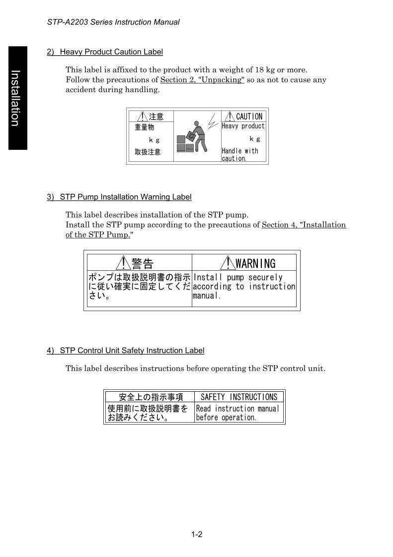
Installation
2) Heavy Product Caution Label
This label is affixed to the product with a weight of 18 kg or more. Follow the precautions of Section 2, "Unpacking" so as not to cause any accident during handling.
重量物
kg
取扱注意
Heavy product
kg
Handle withcaution.
注意 CAUTION! !
3) STP Pump Installation Warning Label
This label describes installation of the STP pump. Install the STP pump according to the precautions of Section 4, "Installation of the STP Pump."
ポンプは取扱説明書の指示に従い確実に固定してください。
Install pump securelyaccording to instructionmanual.
警告! WARNING!
4) STP Control Unit Safety Instruction Label
This label describes instructions before operating the STP control unit.
安全上の指示事項 SAFETY INSTRUCTIONS
使用前に取扱説明書をお読みください。
Read instruction manualbefore operation.
1-2
STP-A2203 Series Instruction Manual
Inst
alla
tion
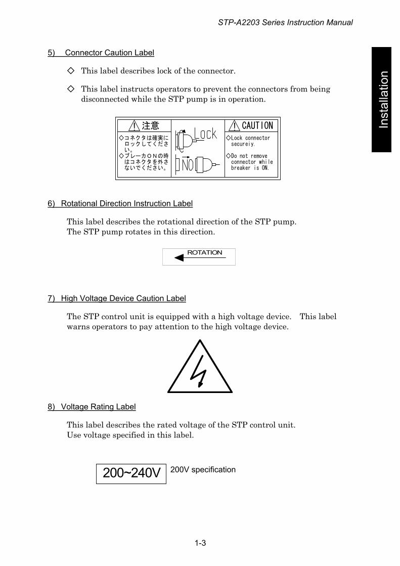
5) Connector Caution Label
◇ This label describes lock of the connector.
◇ This label instructs operators to prevent the connectors from being disconnected while the STP pump is in operation.
◇コネクタは確実に ロックしてくださ い。◇ブレーカONの時 はコネクタを外さ ないでください。
◇Lock connector secureiy.
◇Do not remove connector while breaker is ON.
注意! CAUTION!
6) Rotational Direction Instruction Label
This label describes the rotational direction of the STP pump. The STP pump rotates in this direction.
ROTATION
7) High Voltage Device Caution Label
The STP control unit is equipped with a high voltage device. This label warns operators to pay attention to the high voltage device.
8) Voltage Rating Label
This label describes the rated voltage of the STP control unit. Use voltage specified in this label.
200~240V 200V specification
1-3
STP-A2203 Series Instruction Manual
1-4
Installation
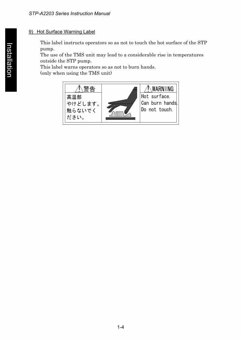
9) Hot Surface Warning Label
This label instructs operators so as not to touch the hot surface of the STP pump. The use of the TMS unit may lead to a considerable rise in temperatures outside the STP pump. This label warns operators so as not to burn hands. (only when using the TMS unit)
警告高温部
やけどします。
触らないでく
ださい。
WARNINGHot surface.Can burn hands.Do not touch.
! !
STP-A2203 Series Instruction Manual
2 Operation Principle of the STP Pump
Inst
alla
tion The STP series pump is a series of a magnetically levitated turbomolecular
pumps, featuring the following:
• Oil free • Low vibration • High reliability
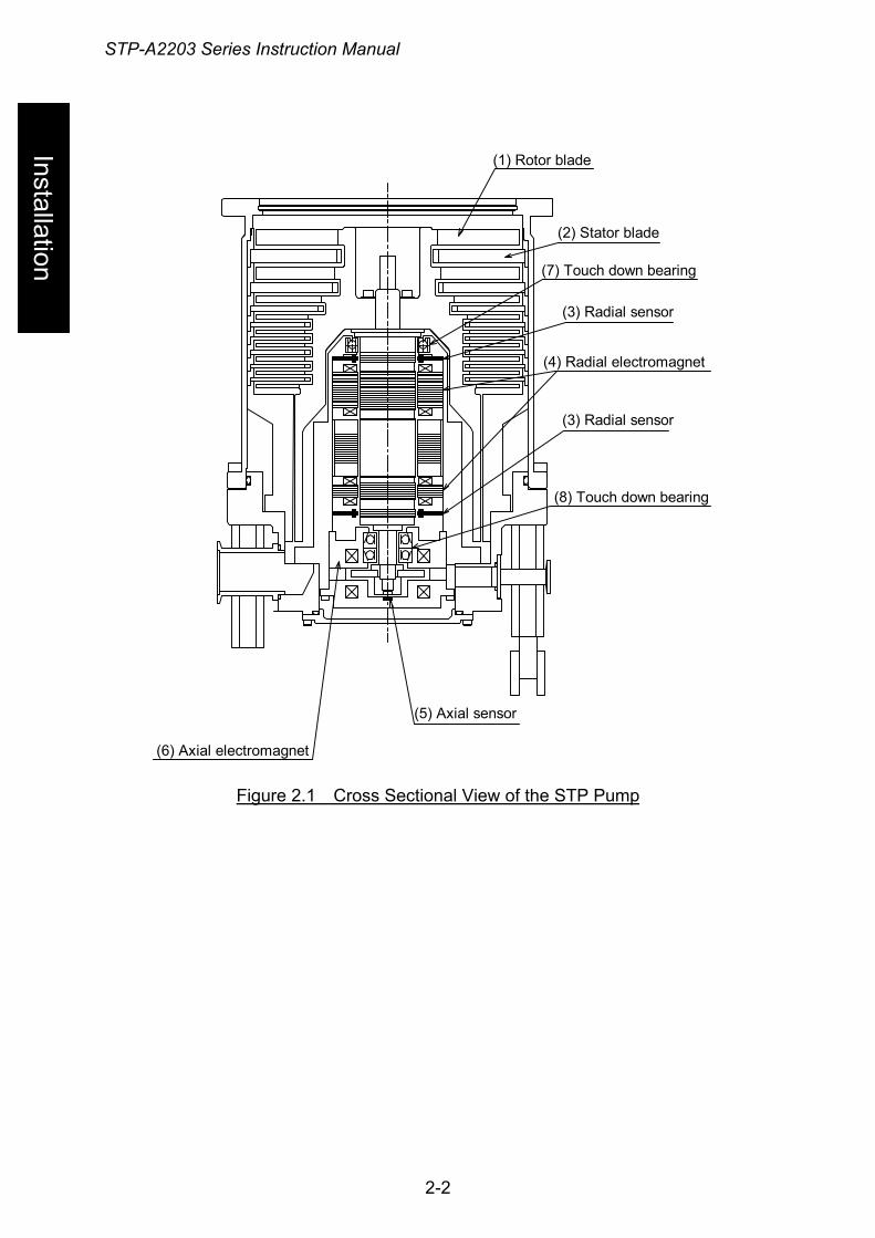
The STP pump is configured so that rotor blade (1) and stator blade (2) are aligned alternately in the axial direction. Gas molecules are pumped from the inlet port to the outlet port by the high speed rotation of the rotor.
The STP pump is configured with a screw channel pump and turbine blade together in the lower side of rotor blade (1) for high-throughput even at a low vacuum range (a few hundred Pa (a few Torr)).
Rotor blade (1) is supported by the magnetic bearing without mechanical contact. Therefore, the STP pump requires no lubrication oil unlike conventional turbomolecular pumps using ball bearings.
The magnetic bearing consists of 5 pairs of active magnetic bearings. The rotor is supported in the radial direction by 4 pairs of radial direction active magnetic bearings that consist of radial sensor (3) and radial electromagnet (4). A pair of axial direction active magnetic bearings consists of axial sensor (5) and axial electromagnet (6) to support the rotor in the axial direction. Because the rotor is supported without mechanical contact, it can rotate at low vibration.
There is less heat generated from magnetic bearings because there is no friction. Therefore the STP pump requires no cooling. However, the STP pump requires water or air cooling during baking and gas pumping. Taking into consideration a breakage of magnetic bearings, touch down bearings (7) and (8) coated with solid lubrication have been installed. They do not contact with the rotor during the rated operation.
A radial sensor, an axial sensor, a rotation speed sensor and a temperature sensor always monitor the magnetic bearing as well as the rotor. If an abnormality/error occurs, the rotor will stop.
2-1
STP-A2203 Series Instruction Manual
Installation
(1) Rotor blade
(2) Stator blade
(7) Touch down bearing
(3) Radial sensor
(4) Radial electromagnet
(3) Radial sensor
(8) Touch down bearing
(5) Axial sensor
(6) Axial electromagnet
Figure 2.1 Cross Sectional View of the STP Pump
2-2
STP-A2203 Series Instruction Manual
3 Unpacking
Inst
alla
tion 3.1 Unpacking the STP Pump and the STP Control Unit
Check the following before unpacking the STP pump and STP control unit.
• Check the package for bruises, breakage, wetness, and other. If there is any abnormality/error or it is judged necessary to return the
product, contact BOC Edwards or the selling agency.
• Check the contents of the package. See Section 3.2, "Accessories."
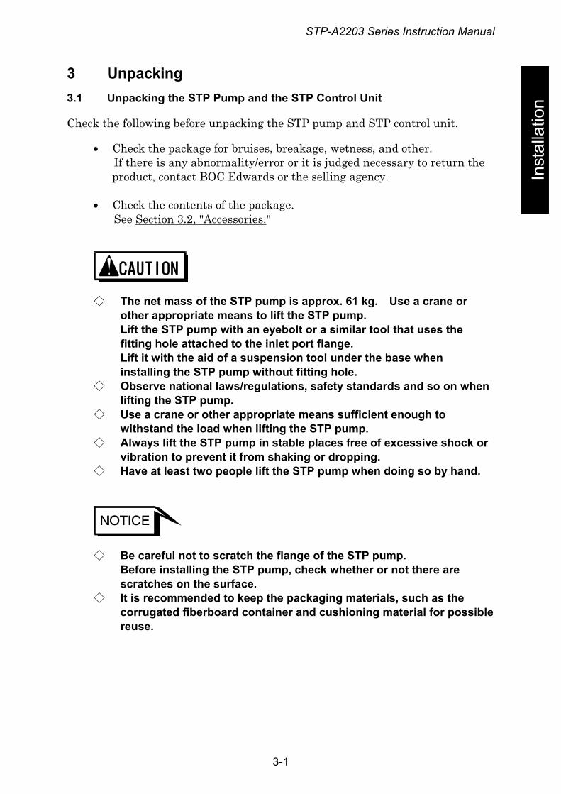
◇ The net mass of the STP pump is approx. 61 kg. Use a crane or other appropriate means to lift the STP pump. Lift the STP pump with an eyebolt or a similar tool that uses the fitting hole attached to the inlet port flange. Lift it with the aid of a suspension tool under the base when installing the STP pump without fitting hole.
◇ Observe national laws/regulations, safety standards and so on when lifting the STP pump.
◇ Use a crane or other appropriate means sufficient enough to withstand the load when lifting the STP pump.
◇ Always lift the STP pump in stable places free of excessive shock or vibration to prevent it from shaking or dropping.
◇ Have at least two people lift the STP pump when doing so by hand.
◇ Be careful not to scratch the flange of the STP pump. Before installing the STP pump, check whether or not there are scratches on the surface.
◇ It is recommended to keep the packaging materials, such as the corrugated fiberboard container and cushioning material for possible reuse.
3-1
STP-A2203 Series Instruction Manual
3-2
Installation
Figure 3.1 Example of Lifting the STP Pump
3.2 Accessories
Table 3.1 Accessories
Item Q’ty Remarks STP control unit 1 Primary power cable*1 1 STP connection cable*1 1 Inlet port cover 1 Outlet port cover 1 STP connector cover 1 Blank flange for purge port 1 KF10 Clamping ring for purge port 1 KF10 O-ring washer for purge port 1 KF10 Leg 4 Leg with a caster 4 Instruction Manual 1
Table 3.2 Optional Accessories
Item Q’ty Remarks TMS connection cable*1 1 Electromagnetic valve for cooling water 1 (for TMS connection cable) TMS heater 1 Attached to the STP pump
250 V, 3 A 1 For F1 Spare fuses 250 V, 0.5 A 1 For F2
*1 : The standard cable length is 5 m. Both 10m and 20m are available. Contact BOC Edwards on other specifications.
STP-A2203 Series Instruction Manual
Inst
alla
tion
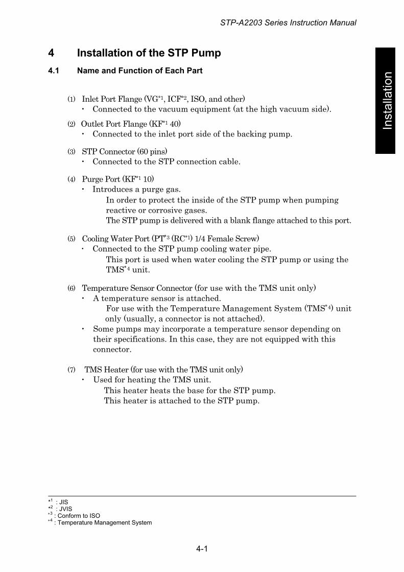
4 Installation of the STP Pump 4.1 Name and Function of Each Part
(1) Inlet Port Flange (VG*1, ICF*2, ISO, and other) ・ Connected to the vacuum equipment (at the high vacuum side).
(2) Outlet Port Flange (KF*1 40) ・ Connected to the inlet port side of the backing pump.
(3) STP Connector (60 pins) ・ Connected to the STP connection cable.
(4) Purge Port (KF*1 10) ・ Introduces a purge gas.
In order to protect the inside of the STP pump when pumping reactive or corrosive gases. The STP pump is delivered with a blank flange attached to this port.
(5) Cooling Water Port (PT∗3 (RC*1) 1/4 Female Screw) ・ Connected to the STP pump cooling water pipe.
This port is used when water cooling the STP pump or using the TMS∗4 unit.
(6) Temperature Sensor Connector (for use with the TMS unit only) ・ A temperature sensor is attached.
For use with the Temperature Management System (TMS∗4) unit only (usually, a connector is not attached).
・ Some pumps may incorporate a temperature sensor depending on their specifications. In this case, they are not equipped with this connector.
(7) TMS Heater (for use with the TMS unit only)
・ Used for heating the TMS unit. This heater heats the base for the STP pump. This heater is attached to the STP pump.
*1 : JIS *2 : JVIS ∗3 : Conform to ISO ∗4 : Temperature Management System
4-1
STP-A2203 Series Instruction Manual
Installation
(1) Inlet port flange
(7) TMS heater
(5) Cooling water port(6) Temperature sensor connector
(3) STP connector(2) Outlet port flange
(4) Purge port
Figure 4.1 Configuration of the STP Pump
4-2
STP-A2203 Series Instruction Manual
4.2 Precautions Before Installation
Inst
alla
tion 4.2.1 Operating Environment
◇ Check the properties of the gas to be used, referring to the Material
Safety Data Sheet (MSDS) you obtain from the gas supplier. And, keep MSDS and a safety advice of gas supplier. Take measures according to MSDS to prevent an accident when using toxic, reactive or combustible gases. Dilute the gas to be used with the inert gas controlled if necessary. And, take measures according to MSDS to prevent an accident caused by exhaust gas.
◇ The STP series models are chemical specific pumps: chlorine or
fluorine system gases can be used with these models. When you use gases including alkaline metals, but excluding Li, gases including Ga, Hg, In, or Sn, or HBr, contact BOC Edwards (See Section 1.1, "Usable Gases").
◇ If the STP pump is used in an area with radiation, contact BOC Edwards.
Install the STP pump in a place meeting the following requirements: Ambient Temperature 0 to 40 °C Ambient Relative Humidity 30 to 95 % (no dew condensing) Environment • A place free of externally-applied mechanical
shock. • A place free of a heat source
(Keep clear of the heat source or attach a thermal shield plate).
• A place free of a strong magnetic field (Range: up to 15 mT (150 G) in the axial direction, and up to 3 mT (30 G) in the radial direction with respect to the rotational axis of the STP pump).
• A place free of a strong electric field. • A place free of exposure to radiation. • No discharge of high voltage (more than 500 V)
(If more than 500 V is discharged, contact BOC Edwards).
STP Pump Installation Equipment Conditions
• Install the STP pump securely so that foreign materials will easily fall into the STP pump (Ex.: Si wafers or samples are positioned above the STP pump) (To prevent foreign materials from falling into the STP pump, design a shield plate with large conductance).
4-3
STP-A2203 Series Instruction Manual
4.2.2 Installation Area
Installation
Leave enough space for the following in addition to that for the STP pump:
• Space for maintenance and inspection • Space for connecting cables
◇ The minimum bending radius of the STP connection cable is 100 mm. DO NOT excessively bend the cables and beware of any obstacles when installing the STP pump. Also, leave enough space to install other cables without bending them excessively.
◇ The L-type STP connection cable is also offered. Contact BOC Edwards if necessary.
4.2.3 Bench
A bench must be prepared by the customer to secure the STP pump. The shape and size of the bench differ depending upon the type of STP pump. Follow the precautions of the WARNING, CAUTION, or NOTICE (See Section 4.3.3, "How to Secure the STP Pump").
◇ The STP pump is provided with a high-speed rotor. Any internal abnormality/error may result in a jump in rotational torque leading to personal injury or peripheral equipment damage. Design and secure the bench for the STP pump so that it can withstand the maximum torque generated due to the occurrence of an abnormality/error. Refer to Section 4.3.3, "How to Secure the STP Pump" for abnormal torque.
◇ Secure the customer-prepared bench and the vacuum equipment on the floor or peripheral equipment and other equipment in accordance with the customer application. NEVER move them while the STP pump is in operation.
4-4

STP-A2203 Series Instruction Manual
Inst
alla
tion
◇ Confirm the dimensions by the external appearance of the STP pump when designing the bench. The bolt may not be able to be inserted from the lower side of the inlet port according to the shape of the inlet port flange. When the external appearance of the STP pump is not in the manual, contact BOC Edwards.
4-5
STP-A2203 Series Instruction Manual
4.3 How to Install the STP Pump
Installation
Install the STP pump to the vacuum equipment as shown in Figure 4.2.
The STP pump can beinstalled through thedamper (optionalaccessory)
Vacuum Equipment
Inlet Port Inlet Port Flange
Vacuum Valve
Dry Pump, and other
BackingPump
Outlet Port Flange
To Power Supply Power Cable
STPControl Unit
STP Connection Cable
*TMS Connection Cable
Remote Cable
To Vacuum Equipment Control Circuit
*The TMS connction cable is usedonly for the STP pump with theTMS unit
Fron
t Pan
el
Figure 4.2 Installation of the STP Pump to the Vacuum Equipment
4-6
STP-A2203 Series Instruction Manual
4.3.1 Cleaning the Seal
Inst
alla
tion Inspect the seals of inlet and outlet port flanges for dirt or oil spots before
installing the STP pump to the vacuum equipment. Take the following measures for cleaning the seals:
• Clean off with a pure gas. • Wipe with proper solvent (such as alcohol).
◇ A splinter shield is attached to the inlet port flange to prevent foreign materials from falling into the STP pump. Always leave the splinter shield attached during operation.
◇ The wipes used for clean the flange of the pump might become hazardous waste depending upon the solvent (alcohol). Dispose of the contaminated wipes appropriately according to the regulations of each national and/or local government.
◇ The splinter shield cannot perfectly prevent foreign materials from falling into the STP pump. DO NOT install the STP pump in such a manner that foreign materials can easily fall into it (for example, Si wafers or samples are positioned above the STP pump). If installing the STP pump in such a manner, always attach a shield plate with sufficient conductance above the STP pump to prevent foreign materials from falling into it. Foreign materials falling into the STP pump through the splinter shield may result in product damage.
◇ Be careful not to scratch the flange of the STP pump. Check whether or not there are scratches on the surface, before installing the STP pump.
4-7
STP-A2203 Series Instruction Manual
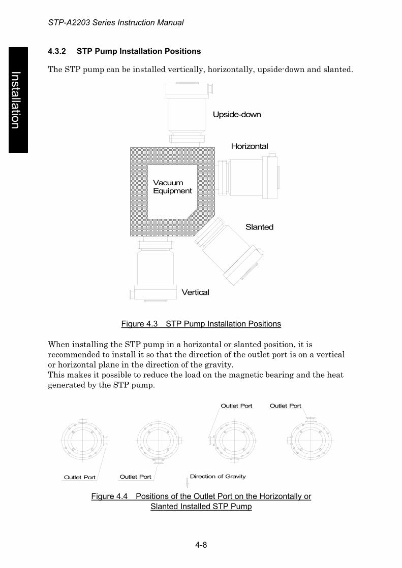
4.3.2 STP Pump Installation Positions
Installation
The STP pump can be installed vertically, horizontally, upside-down and slanted.
Upside-down
Horizontal
Slanted
Vertical
VacuumEquipment
Figure 4.3 STP Pump Installation Positions
When installing the STP pump in a horizontal or slanted position, it is recommended to install it so that the direction of the outlet port is on a vertical or horizontal plane in the direction of the gravity. This makes it possible to reduce the load on the magnetic bearing and the heat generated by the STP pump.
Outlet Port
Outlet Port
Outlet Port
Outlet Port
Direction of Gravity
Figure 4.4 Positions of the Outlet Port on the Horizontally or
Slanted Installed STP Pump
4-8
STP-A2203 Series Instruction Manual
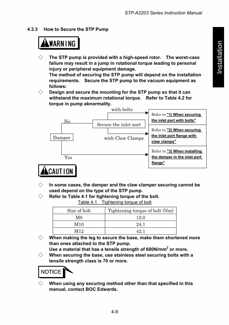
4.3.3 How to Secure the STP Pump
Inst
alla
tion
◇ The STP pump is provided with a high-speed rotor. The worst-case failure may result in a jump in rotational torque leading to personal injury or peripheral equipment damage. The method of securing the STP pump will depend on the installation requirements. Secure the STP pump to the vacuum equipment as follows:
◇ Design and secure the mounting for the STP pump so that it can withstand the maximum rotational torque. Refer to Table 4.2 for torque in pump abnormality.
o
◇ Inus
◇ Re
◇ WthUs
◇ Wte
◇ Wm
Damper
someed defer to
hen man one a m
hen snsile
hen uanual
Yes
N
cases, the damper apend on the type of t Table 4.1 for tighten
Table 4.1 Tight
Size of bolt TiM8
M10 M12
aking the leg to secues attached to the STaterial that has a ten
ecuring the base, usestrength class is 70 o
sing any securing me, contact BOC Edward
with bolts
with Claw Clamps
Secure the inlet port
nd the claw clamhe STP pump. ing torque of the ening torque of bo
ghtening torque o12.0 24.1 42.1
re the base, makP pump. sile strength of 60 stainless steel sr more.
thod other than ts.
4-9
Refer to "1) When securing the inlet port with bolts"
Refer to "2) When securing the inlet port flange with claw clamps"
Refer to "3) When installing the damper in the inlet port flange"
per securing cannot be
bolt. lt
f bolt (Nm)
e them shortened more
0N/mm2 or more. ecuring bolts with a
hat specified in this
STP-A2203 Series Instruction Manual
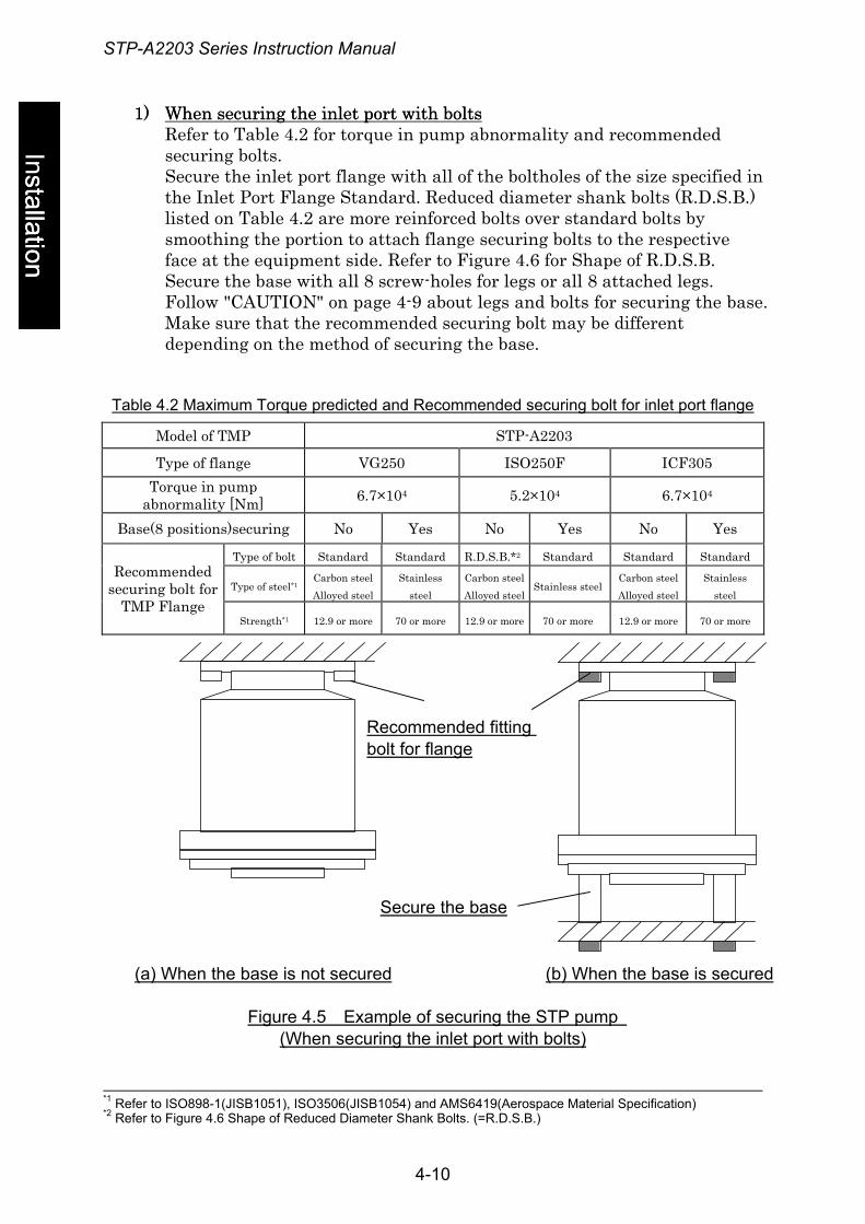
1) When securing the inlet port with bolts1) When securing the inlet port with bolts Refer to Table 4.2 for torque in pump abnormality and recommended securing bolts. Secure the inlet port flange with all of the boltholes of the size specified in the Inlet Port Flange Standard. Reduced diameter shank bolts (R.D.S.B.) listed on Table 4.2 are more reinforced bolts over standard bolts by smoothing the portion to attach flange securing bolts to the respective face at the equipment side. Refer to Figure 4.6 for Shape of R.D.S.B. Secure the base with all 8 screw-holes for legs or all 8 attached legs. Follow "CAUTION" on page 4-9 about legs and bolts for securing the base. Make sure that the recommended securing bolt may be different depending on the method of securing the base.
Installation stallation
Table 4.2 Maximum Torque predicted and Recommended securing bolt for inlet port flange
Model of TMP STP-A2203
Type of flange VG250 ISO250F ICF305 Torque in pump
abnormality [Nm] 6.7×10⁴ 5.2×10⁴ 6.7×10⁴
Base(8 positions)securing No Yes No Yes No Yes
Type of bolt Standard Standard R.D.S.B.*2 Standard Standard Standard
Type of steel*1 Carbon steel Alloyed steel
Stainless steel
Carbon steel Alloyed steel
Stainless steel Carbon steel Alloyed steel
Stainless steel
Recommended securing bolt for
TMP Flange Strength*1 12.9 or more 70 or more 12.9 or more 70 or more 12.9 or more 70 or more
Recommended fitting bolt for flange
Secure the base
(a) When the base is not secured (b) When the base is secured
Figure 4.5 Example of securing the STP pump (When securing the inlet port with bolts)
*1 Refer to ISO898-1(JISB1051), ISO3506(JISB1054) and AMS6419(Aerospace Material Specification) *2 Refer to Shape of Reduced Diameter Shank Bolts. (=R.D.S.B.) Figure 4.6
4-10
STP-A2203 Series Instruction Manual
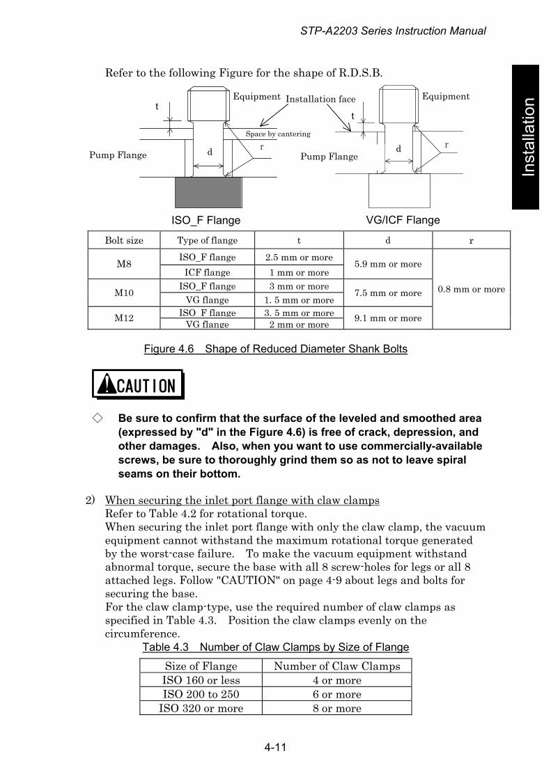
Refer to the following Figure for the shape of R.D.S.B.
Inst
alla
tion
Bolt size Type of flange t d r ISO_F flange 2.5 mm or more M8
ICF flange 1 mm or more 5.9 mm or more
ISO_F flange 3 mm or more M10
VG flange 1. 5 mm or more 7.5 mm or more
ISO_F flange 3. 5 mm or more M12 VG flange 2 mm or more 9.1 mm or more
0.8 mm or more
Figure 4.6 Shape of Reduced Diameter Shank Bolts
◇ Be sure to confirm that the surface of the leveled and smoothed area (expressed by "d" in the Figure 4.6) is free of crack, depression, and other damages. Also, when you want to use commercially-available screws, be sure to thoroughly grind them so as not to leave spiral seams on their bottom.
2) When securing the inlet port flange with claw clamps Refer to Table 4.2 for rotational torque. When securing the inlet port flange with only the claw clamp, the vacuum equipment cannot withstand the maximum rotational torque generated by the worst-case failure. To make the vacuum equipment withstand abnormal torque, secure the base with all 8 screw-holes for legs or all 8 attached legs. Follow "CAUTION" on page 4-9 about legs and bolts for securing the base. For the claw clamp-type, use the required number of claw clamps as specified in Table 4.3. Position the claw clamps evenly on the circumference.
Table 4.3 Number of Claw Clamps by Size of Flange
Size of Flange Number of Claw Clamps ISO 160 or less 4 or more ISO 200 to 250 6 or more
ISO 320 or more 8 or more
VG/ICF Flange ISO_F Flange
Equipment
Pump Flange
Installation face Equipment
Pump Flange
Space by cantering
t
d r
t
d r
4-11
STP-A2203 Series Instruction Manual
Installation stallation
Figure 4.7 Figure 4.7 (When securin
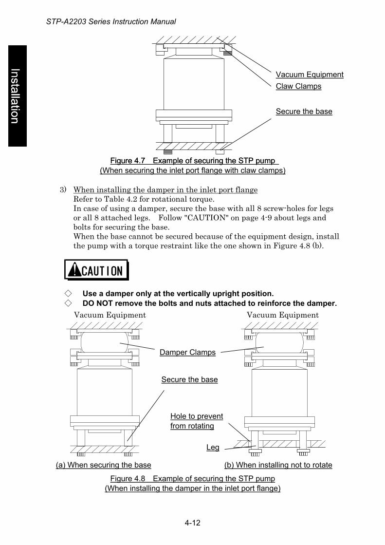
3) When installing the dRefer to Table 4.2 forIn case of using a damor all 8 attached legsbolts for securing theWhen the base cannothe pump with a torq
◇ Use a damper only◇ DO NOT remove th
(a) When securing the base
Vacuum Equipment
Figure 4.8 (When instal
Example of securing the STP pump Example of securing the STP pumpg the inlet port flange with claw clam
s t
amper in the inlet port flange rotational torque.
per, secure the base with all 8 scr. Follow "CAUTION" on page 4-9 base. t be secured because of the equipmue restraint like the one shown in
at the vertically upright positione bolts and nuts attached to rein
(b) When insta
Leg
Hole to preventfrom rotating
Damper Clamps
Secure the base
Vacuum
Example of securing the STP pumpling the damper in the inlet port flang
4-12
Claw Clamp
Secure the base
Vacuum Equipmen
ps)
ew-holes for legs about legs and
ent design, install Figure 4.8 (b).
. force the damper.
lling not to rotate
Equipment
e)
STP-A2203 Series Instruction Manual
4.3.4 Vacuum Piping
Inst
alla
tion
◇ DO NOT open the STP pump through the inlet flange to atmospheric air while the STP pump is running. If atmospheric air flows into the STP pump, it may not function normally.
◇ Depending upon the type of the backing pump used, atmospheric air may reverse flow into the STP pump when the backing pump stops. Attach a vacuum valve to the middle of the piping between the STP pump outlet port flange and the backing pump, and close the vacuum valve when the backing pump stops.
In order to let the STP pump bring its performance into full play, follow the precautions below:
1) Be careful not to scratch the flange of the STP pump. Before installing the STP pump, check whether or not there are scratches on the surface.
2) Use stainless steel or aluminum alloy tubes with a low gas loss to connect the vacuum equipment to the STP pump.
3) Take measures for minimizing leakage. It is also necessary to degrease the tubes as regularly as possible to keep the gas loss as low as possible.
4) It is recommended to use a backing pump of pumping speed 1300 L/min or more. However, the pressure at the inlet and outlet ports varies with the flow rate of gas, capacity of the vacuum equipment, length and material of the piping. Select a backing pump in accordance with the capacity and starting method (simultaneous starting, starting after generating roughing vacuum) suitable for the vacuum equipment you use.
5) Connect the STP pump and the backing pump using stainless steel or aluminum alloy tubing, flexible tubing, vacuum rubber or Teflon tubing, and other. The following measures can be used to avoid the transmission of the vibration of the backing pump to the STP pump and the vacuum equipment. • DO NOT place the backing pump on the same floor as the vacuum
equipment. • Locate the backing pump on a vibration-proof table.
Attain 1/3 or less of the rotational speed of the backing pump, when adjusting the inherent frequency of the backing pump installed on a vibration-proof table.
• Attach a weight to the piping from the backing pump, or secure the piping to a rigid, heavy object free of vibration.
• Use a tube of high flexibility.
4-13
STP-A2203 Series Instruction Manual
6) Depending upon the type of the backing pump used, oil vapor may contaminate the inside of the STP pump. Some oil viscosity could cause a malfunction when there is a strong reverse flow of oil. Take the following measures to ensure the correct flow of oil:
6) Depending upon the type of the backing pump used, oil vapor may contaminate the inside of the STP pump. Some oil viscosity could cause a malfunction when there is a strong reverse flow of oil. Take the following measures to ensure the correct flow of oil:
Installation stallation
• Attach a vacuum valve to the middle of the piping between the STP pump outlet port flange and the backing pump.
• Attach a vacuum valve to the middle of the piping between the STP pump outlet port flange and the backing pump.
• Attach an absorption trap adjacent to the vacuum valve. • Attach an absorption trap adjacent to the vacuum valve.
Piping at the Inlet Port FlangePiping at the Inlet Port Flange Attach the inlet port to the high vacuum side.
Maximum working pressure: 2.7 Pa [0.02 Torr] (for water cooled) Pressure at the inlet port flange 1.7 Pa [0.013 Torr] (when TMS unit is used) applicable continuously
Piping at the Outlet Port Flange Attach the outlet port to the inlet port flange of the backing pump (primary side pump).
Allowable backing pressure: 400 Pa [3 Torr] (for water cooled, Pressure at the outlet port flange when TMS unit is used) applicable continuously
◇ Upper pressure is applicable under the following conditions: • The N2 or other similar gas is vacuumed. • The backing pump (pumping speed: 1,300 L/min) is used.
◇ To attain the ultimate pressure shown in Table 13.1, "Specifications for the STP Pump," set the pressure at the outlet port flange to 1.3 Pa (10-2 Torr) or less.
4-14
STP-A2203 Series Instruction Manual
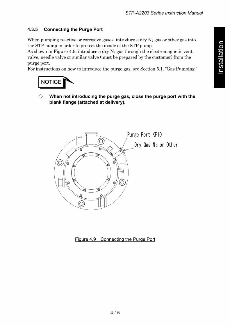
4.3.5 Connecting the Purge Port
Inst
alla
tion When pumping reactive or corrosive gases, introduce a dry N2 gas or other gas into
the STP pump in order to protect the inside of the STP pump. As shown in Figure 4.9, introduce a dry N2 gas through the electromagnetic vent. valve, needle valve or similar valve (must be prepared by the customer) from the purge port. For instructions on how to introduce the purge gas, see Section 5.1, "Gas Pumping."
◇ When not introducing the purge gas, close the purge port with the blank flange (attached at delivery).
Purge Port KF10
Dry Gas N or Other2
Figure 4.9 Connecting the Purge Port
4-15
STP-A2203 Series Instruction Manual
4.3.6 Connecting the Cooling Water Valve (For use with TMS unit only)
Installation
◇ DO NOT apply excessive force to the cable for cooling water valve. ◇ Check the indication of the cooling water valve ports. ◇ Secure the cooling water pipe to prevent water leakage.
◇ Procure and connect the cooling water pipe at your company. ◇ Use clean water as much as possible.
Cooling water containing foreign materials may corrode or clog the cooling water pipe and the cooling water valve.
◇ When the cooling system is clogged with foreign materials, clogs may possibly be removed by feeding cooling water reversibly.
◇ When this unit is not to be used for a long period of time or it is to be moved after use, introduce compressed air from one side of the cooling water port so that no water will remain inside.
◇ The joint for the cooling water port is made of stainless steel. To prevent corrosion, connect the stainless steel joint.
Female screw PT (RC) 1/4 is used in the cooling water port.
Use cooling water under the following conditions:
Amount of water: 2 L/min Temperature: 5 to 25 °C Water pressure: 2.9×10⁵Pa (3kgf/cm2) or less
4-16
STP-A2203 Series Instruction Manual
Inst
alla
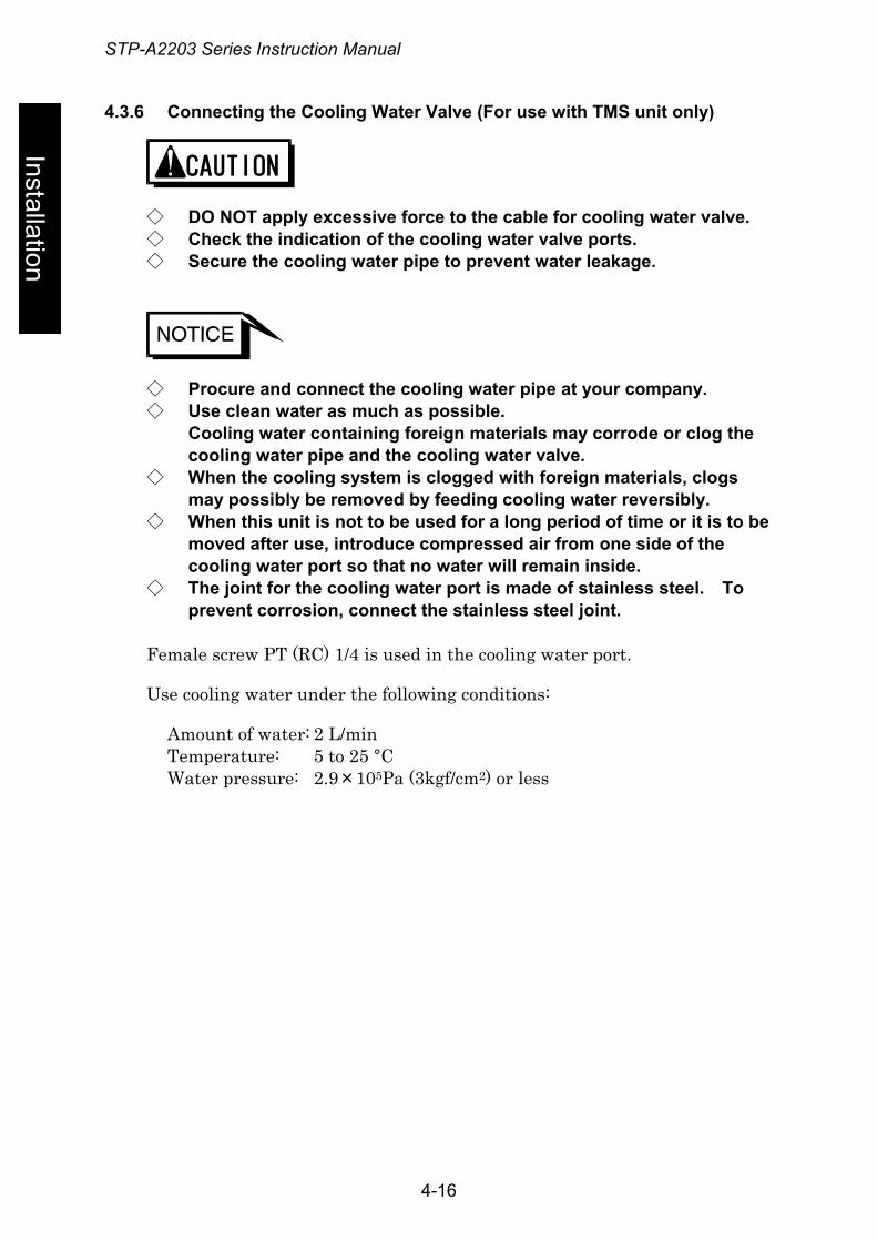
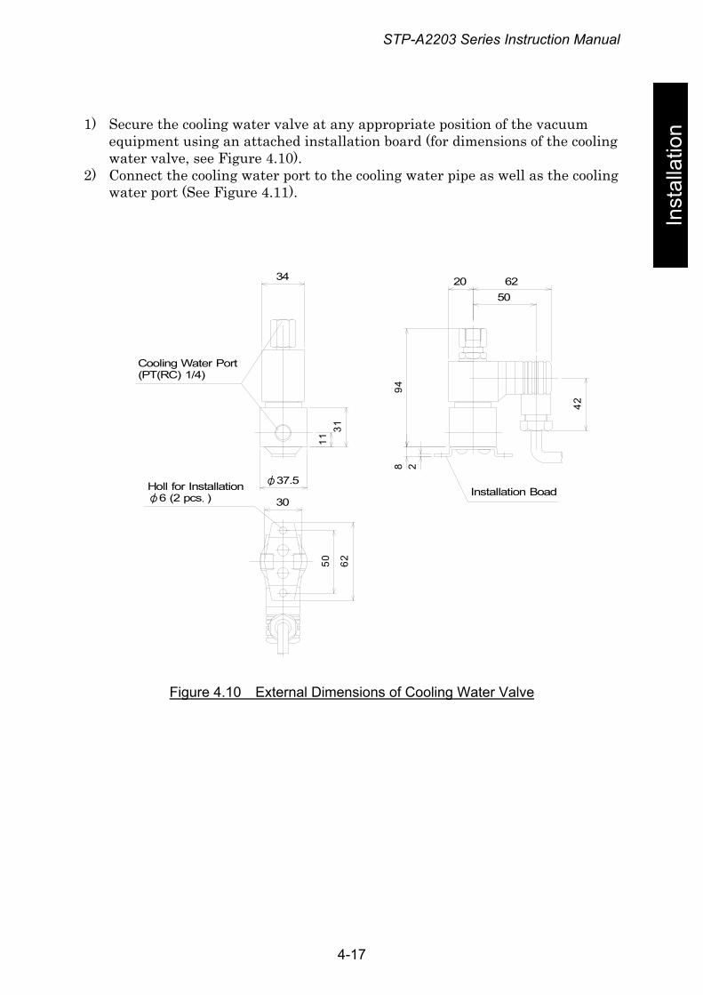
tion 1) Secure the cooling water valve at any appropriate position of the vacuum
equipment using an attached installation board (for dimensions of the cooling water valve, see Figure 4.10).
2) Connect the cooling water port to the cooling water pipe as well as the cooling water port (See Figure 4.11).
34
50 62
42
948
20 6250
2
1131
30
φ37.5
Cooling Water Port(PT(RC) 1/4)
Holl for Installationφ6 (2 pcs.) Installation Boad
Figure 4.10 External Dimensions of Cooling Water Valve
4-17
STP-A2203 Series Instruction Manual
Installation
Cooling WaterPort
CoolingWaterPipe
Cooling WaterValve
N.C
N.OCOM
To Vacuum EquipmentWater Pipe
Cooling WaterPort
To Vacuum EquipmentWater Pipe
Figure 4.11 Piping of Cooling Water Valve
4-18
STP-A2203 Series Instruction Manual
5 Gas Pumping, Cooling and Baking the STP Pump
Inst
alla
tion 5.1 Gas Pumping
◇ When pumping gases, they may remain in the STP pump. Introduce a purge gas and then exhaust all gasses. Residual gases in the STP pump may cause an accident when the STP pump is removed. Confirm the characteristics of gases to be used, referring to the Material Safety Data Sheet (MSDS) you obtain from the gas supplier.
◇ The STP series models are chemical specific pumps; chlorine or fluorine system gases can be used with these models. When you use gases including alkaline metals, but excluding Li, gases including Ga, Hg, In, or Sn, or HBr, contact BOC Edwards.
◇ Cool the STP pump to prevent the STP pump from overheating when pumping gases
5.1.1 How to Introduce a Purge Gas
◇ When pumping reactive or corrosive gases, introduce a purge gas to protect the inside of the STP pump. Doing so may result in product damage.
Connect a needle valve or a similar part to the purge port and introduce a dry N2 gas or other gas to perform a gas purge (See Section 4.3.5, "Connecting the Purge Port").
◇ The proper amount of the gas purge is approx. 3.4×10 -2 Pa·m3/s (20SCCM).
◇ The allowable gas pressure ranges from zero [atmospheric pressure] to 4.9×10⁴Pa [gauge pressure] (zero [atmospheric pressure] to 0.5 kgf/cm2 [gauge pressure]).
◇ High-pressure at the inlet port may result in a noise. This is no abnormality/error.
5-1
STP-A2203 Series Instruction Manual
5.2 Cooling the STP Pump
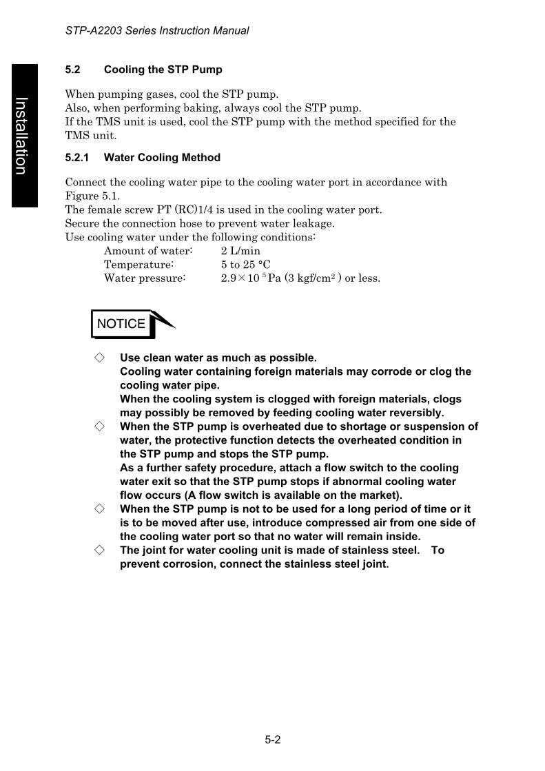
Installation
When pumping gases, cool the STP pump. Also, when performing baking, always cool the STP pump. If the TMS unit is used, cool the STP pump with the method specified for the TMS unit.
5.2.1 Water Cooling Method
Connect the cooling water pipe to the cooling water port in accordance with Figure 5.1. The female screw PT (RC)1/4 is used in the cooling water port. Secure the connection hose to prevent water leakage. Use cooling water under the following conditions: Amount of water: 2 L/min Temperature: 5 to 25 °C Water pressure: 2.9×10 5 Pa (3 kgf/cm2 ) or less.
◇ Use clean water as much as possible. Cooling water containing foreign materials may corrode or clog the cooling water pipe. When the cooling system is clogged with foreign materials, clogs may possibly be removed by feeding cooling water reversibly.
◇ When the STP pump is overheated due to shortage or suspension of water, the protective function detects the overheated condition in the STP pump and stops the STP pump. As a further safety procedure, attach a flow switch to the cooling water exit so that the STP pump stops if abnormal cooling water flow occurs (A flow switch is available on the market).
◇ When the STP pump is not to be used for a long period of time or it is to be moved after use, introduce compressed air from one side of the cooling water port so that no water will remain inside.
◇ The joint for water cooling unit is made of stainless steel. To prevent corrosion, connect the stainless steel joint.
5-2
STP-A2203 Series Instruction Manual
5.3 Baking the STP Pump
Inst
alla
tion To attain a less pressure in a shorter time and reduce the exhaust time, bake the
vacuum equipment and STP pump.
◇ The surfaces of the STP pump and its peripheral equipment will become extremely hot when performing baking. NEVER touch them with bare hands.
◇ The TMS unit and the baking heater cannot be used together at the same time.
◇ When baking the STP pump, always cool it to prevent overheating. ◇ Start baking after cooling is started.
Set the temperature of the baking heater to 120 °C or less. ◇ DO NOT pump gases during baking to prevent overheating.
◇ To exhaust the gas discharged from the vacuum equipment and the inner wall of the STP pump, run the STP pump during baking.
5.3.1 Attaching a Baking Heater
1) Install the baking heater (special accessory) near the inlet port flange in the perimeter of the envelope.
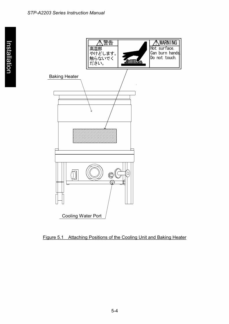
2) Affix the hot surface warning label attached on the surface of the pump seen well. (see Figure 5.1, "Attaching Positions of the Cooling Unit and Baking Heater")
◇ Check the rated voltage of the baking heater before use. (The range of the available voltage of the backing heater (special accessory) is display voltage ±10%.)
◇ Wind the baking heater around the surface of the STP pump tightly. If the baking heater is not wound tightly, the loose parts will overheat.
◇ Procure protective parts for the baking heater, such as an earth leakage breaker or fuses when using the baking heater.
◇ DO NOT apply excessive force to the cable for the baking heater.
5-3
STP-A2203 Series Instruction Manual
Installation
警告高温部やけどします。触らないでください。
WARNINGHot surface.Can burn hands.Do not touch.
! !
Baking Heater
Cooling Water Port
Figure 5.1 Attaching Positions of the Cooling Unit and Baking Heater
5-4
STP-A2203 Series Instruction Manual
6 Installation of the STP Control Unit
Inst
alla
tion 6.1 Name and Function of Each Part
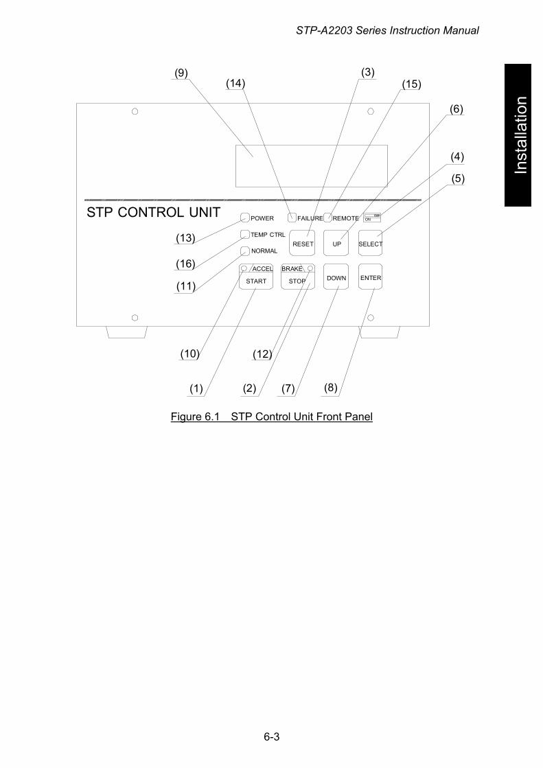
6.1.1 Front Panel
(1) "START" Switch (flat panel switch, green) ・ STP pump rotating function (valid in MANUAL operation only).
(2) "STOP" Switch (flat panel switch, dark gray) ・ STP pump stop operation function (valid in MANUAL operation
only).
(3) "RESET" Switch (flat panel switch, gray) ・ Alarm reset function (valid in MANUAL operation only). ・ Tuning function (valid in MANUAL operation only).
(4) "MANUAL/REMOTE" Changeover Switch (slide switch, black) ・ Operation mode changeover function.
(5) "SELECT" Switch (flat panel switch, gray) ・ LCD display (Confirmation mode change) function (valid in both
MANUAL and REMOTE operations). ・ Setting mode change function (valid in both MANUAL and REMOTE
operations). Press both of "SELECT" and "UP" switches simultaneously to enter
the setting mode.
(6) "UP" Switch (flat panel switch, gray) (7) "DOWN" Switch (flat panel switch, gray)
・ Abnormality/error display change function (valid in both MANUAL and REMOTE operations).
・ Setting content confirmation function (valid in both MANUAL and REMOTE operations).
・ Setting content change function (valid in both MANUAL and REMOTE operations).
(8) "ENTER" Switch (flat panel switch, gray) ・ Setting content determination function (valid in both MANUAL and
REMOTE operations). ・ WARNING message display function (valid in both MANUAL and
REMOTE operations).
6-1
STP-A2203 Series Instruction Manual
(9) LCD
Installation
・ The LCD displays a pump’s operation state, speed, or other messages. ・ The LCD displays an error message when an abnormality/error
occurs in the STP pump.
(10) "ACCEL." Lamp (green LED) ・ Lights during acceleration (ACCELERATION state).
(11) "NORMAL" Lamp (green LED) ・ Lights during rated speed operation (NORMAL OPERATION state).
(12) "BRAKE" Lamp (green LED) ・ Lights during deceleration (BRAKE state).
(13) "POWER" Lamp (green LED) ・ Lights while the power is ON. ・ Goes out while the backup power is being supplied.
(14) "FAILURE" Lamp (red LED) ・ Lights when any of the abnormalities/errors occurs on the STP pump
and the STP control unit. The LCD displays an error message simultaneously.
(15) "REMOTE" Lamp (green LED)
・ Lights while the operation mode is remote.
(16) "TEMP CTRL" Lamp (green LED) ・ Lights while the TMS unit (optional accessory) is in operation.
6-2
STP-A2203 Series Instruction Manual
Inst
alla
tion
STP CONTROL UNITON
RESET UP SELECT
DOWN ENTERSTART STOP
ACCEL BRAKE
POWER
TEMP CTRL
NORMAL
FAILURE REMOTE
(9)(14)
(3)(15)
(6)
(4)
(5)
(13)
(16)
(11)
(10) (12)
(1) (2) (7) (8)
Figure 6.1 STP Control Unit Front Panel
6-3
STP-A2203 Series Instruction Manual
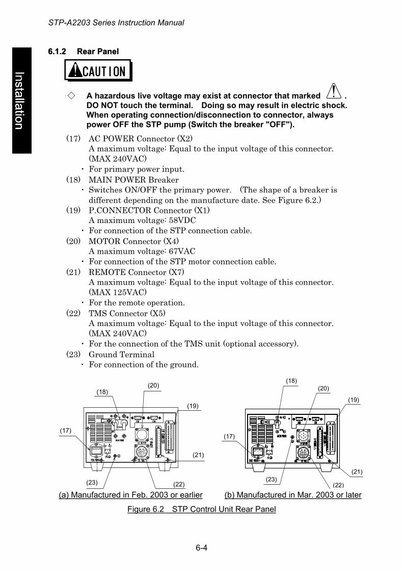
6.1.2 Rear Panel 6.1.2 Rear Panel
Installation stallation
◇ A hazardous live voltage may exist at connector that marked . DO NOT touch the terminal. Doing so may result in electric shock. When operating connection/disconnection to connector, always power OFF the STP pump (Switch the breaker "OFF").
(17) AC POWER Connector (X2) A maximum voltage: Equal to the input voltage of this connector. (MAX 240VAC)
・ For primary power input. (18) MAIN POWER Breaker
・ Switches ON/OFF the primary power. (The shape of a breaker is different depending on the manufacture date. See Figure 6.2.)
(19) P.CONNECTOR Connector (X1) A maximum voltage: 58VDC
・ For connection of the STP connection cable. (20) MOTOR Connector (X4)
A maximum voltage: 67VAC ・ For connection of the STP motor connection cable.
(21) REMOTE Connector (X7) A maximum voltage: Equal to the input voltage of this connector. (MAX 125VAC)
・ For the remote operation. (22) TMS Connector (X5)
A maximum voltage: Equal to the input voltage of this connector. (MAX 240VAC)
・ For the connection of the TMS unit (optional accessory). (23) Ground Terminal
・ For connection of the ground.
(18)
(17)
(20)
(19)
(23) (22)
(21)!
!
!
!
!
O F F
(18)(20)
(19)
(21)
(22)(23)
(17)
(b) Manufactured in Mar. 2003 or later(a) Manufactured in Feb. 2003 or earlier
Figure 6.2 STP Control Unit Rear Panel
6-4
STP-A2203 Series Instruction Manual
6.2 Precautions Before Installation
Inst
alla
tion 6.2.1 Operating Environment
Install the STP control unit in a place meeting the following requirements:
Ambient Temperature 0 to 40 °C
Ambient Relative Humidity 30 to 95% (no dew condensing)
Environment • A place free of exposure to direct sunlight. • A place free of high humidity. • A place free of dust. • A place free of salty air. • A place free of dripping water. • A place free of explosive or inflammable gas. • A place free of corrosive gas. • A place free of radiation. • A place free of strong magnetic and electric fields. • A place free of excessive vibration. • A place free of a source of electric noise.
Installation Condition • Install the STP control unit horizontally (within ±10°C).
6.2.2 Insulation Test
Do not perform the insulation test (insulation resistance test and withstand voltage test) to the STP control unit.
When performing the insulation test to your equipment, turn "OFF" the STP control unit so that the test voltage is not applied to the STP control unit.
◇ The varistor for the power supply line protection is installed to the
STP control unit. DO NOT perform the insulation test with the varistor installed. Doing so may result in product damage.
6-5
STP-A2203 Series Instruction Manual
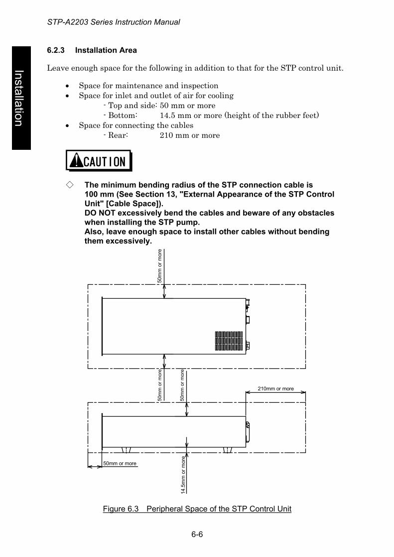
6.2.3 Installation Area
Installation
Leave enough space for the following in addition to that for the STP control unit.
• Space for maintenance and inspection • Space for inlet and outlet of air for cooling
- Top and side: 50 mm or more - Bottom: 14.5 mm or more (height of the rubber feet)
• Space for connecting the cables - Rear: 210 mm or more
◇ The minimum bending radius of the STP connection cable is 100 mm (See Section 13, "External Appearance of the STP Control Unit" [Cable Space]). DO NOT excessively bend the cables and beware of any obstacles when installing the STP pump. Also, leave enough space to install other cables without bending them excessively.
50m
m o
r mor
e50
mm
or m
ore
50m
m o
r mor
e14
.5m
m o
r mor
e
50mm or more
210mm or more
Figure 6.3 Peripheral Space of the STP Control Unit
6-6
STP-A2203 Series Instruction Manual
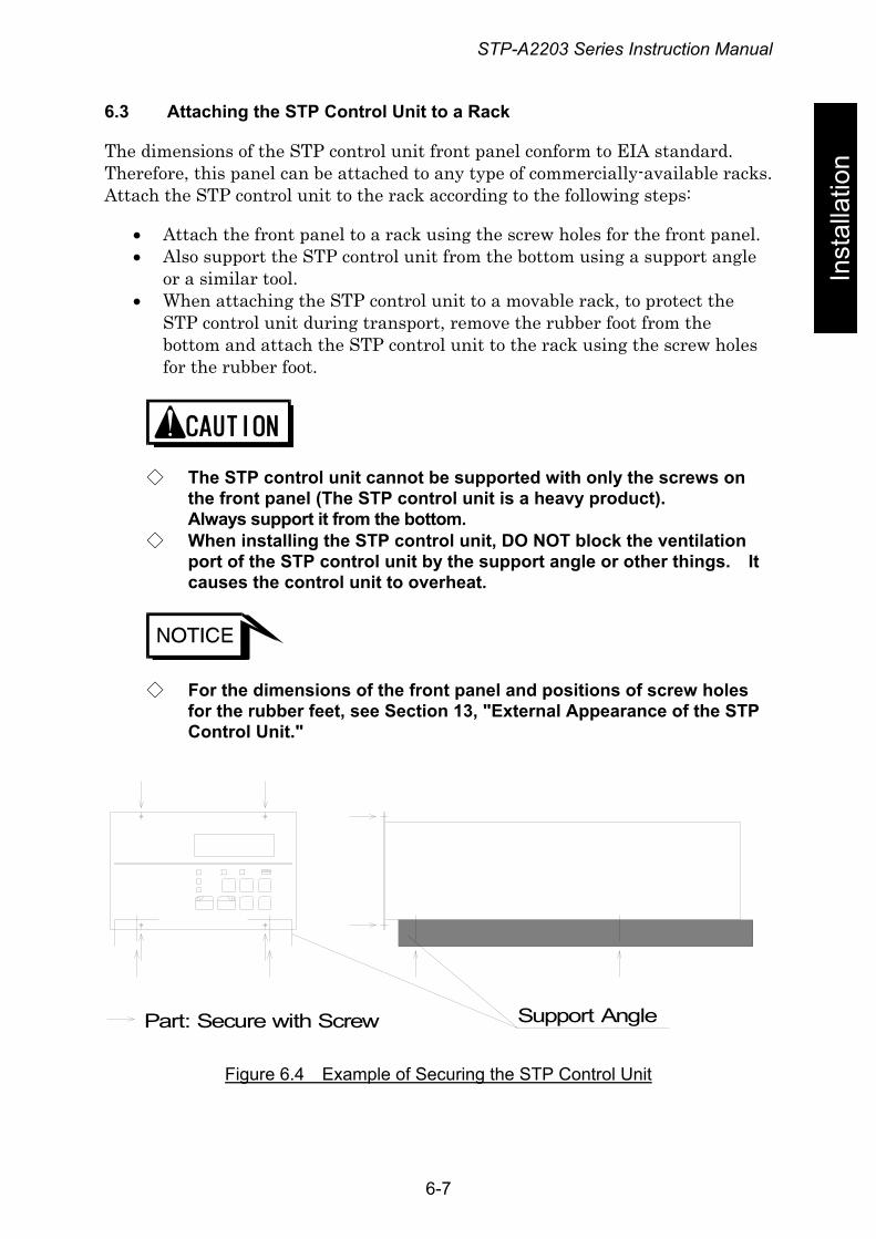
6.3 Attaching the STP Control Unit to a Rack
Inst
alla
tion The dimensions of the STP control unit front panel conform to EIA standard.
Therefore, this panel can be attached to any type of commercially-available racks. Attach the STP control unit to the rack according to the following steps:
• Attach the front panel to a rack using the screw holes for the front panel. • Also support the STP control unit from the bottom using a support angle
or a similar tool. • When attaching the STP control unit to a movable rack, to protect the
STP control unit during transport, remove the rubber foot from the bottom and attach the STP control unit to the rack using the screw holes for the rubber foot.
◇ The STP control unit cannot be supported with only the screws on the front panel (The STP control unit is a heavy product). Always support it from the bottom.
◇ When installing the STP control unit, DO NOT block the ventilation port of the STP control unit by the support angle or other things. It causes the control unit to overheat.
◇ For the dimensions of the front panel and positions of screw holes for the rubber feet, see Section 13, "External Appearance of the STP Control Unit."
Part: Secure with Screw Support Angle
Figure 6.4 Example of Securing the STP Control Unit
6-7
STP-A2203 Series Instruction Manual
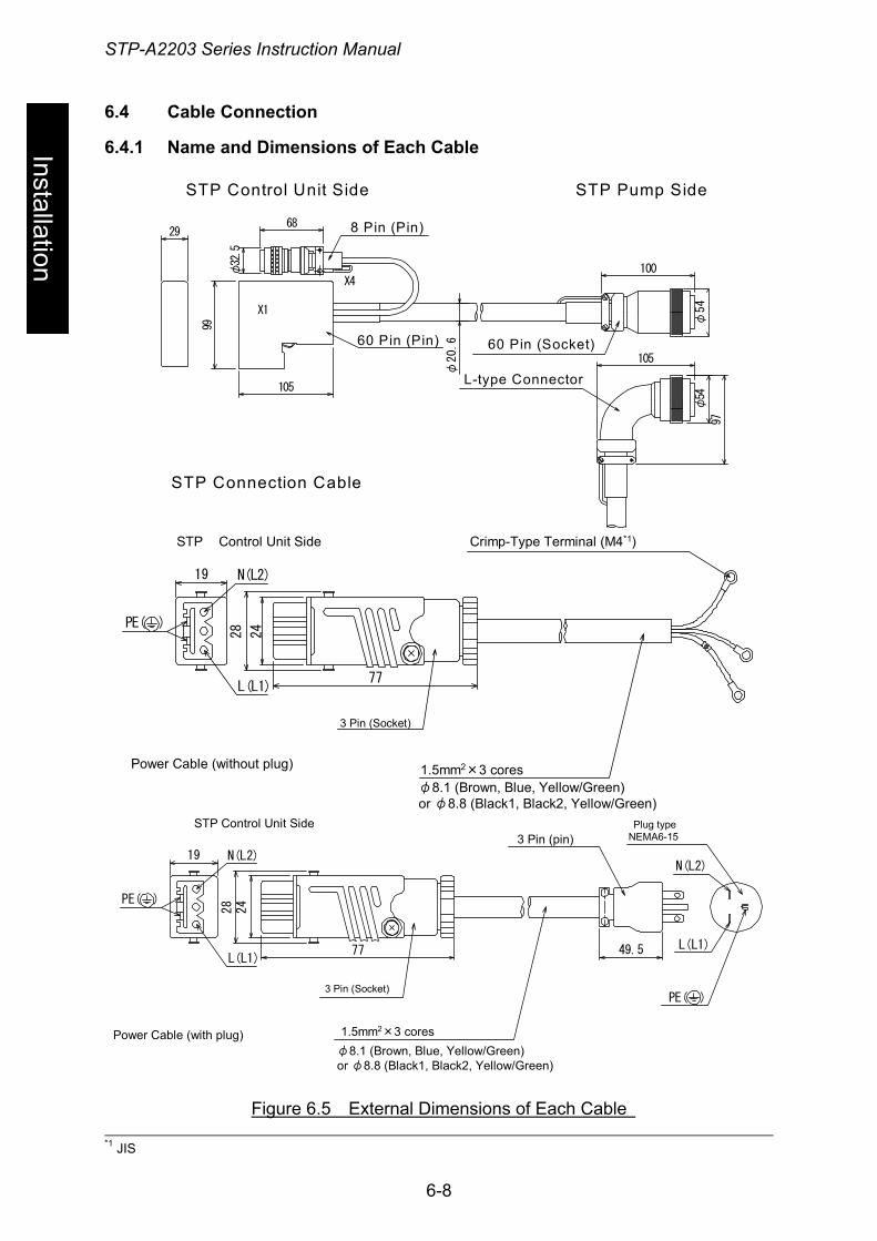
6.4 Cable Connection
Installation
6.4.1 Name and Dimensions of Each Cable
29
φ20.6
105
68φ32.5
99
X1
X4
105
100
φ54
97
φ54
STP Connection Cable
STP Control Unit Side STP Pump Side
L-type Connector
60 Pin (Pin) 60 Pin (Socket)
8 Pin (Pin)
19
28
77
N(L2)
L(L1)
PE( )
Power Cable (without plug)
STP Control Unit Side Crimp-Type Terminal (M4*1)
3 Pin (Socket)
24
1.5mm2×3 coresφ8.1 (Brown, Blue, Yellow/Green)or φ8.8 (Black1, Black2, Yellow/Green)
19
24
28
77
N(L2)
L(L1)
PE( )
49.5
N(L2)
L(L1)
PE( )
STP Control Unit Side
Power Cable (with plug)
3 Pin (pin)Plug type
NEMA6-15
3 Pin (Socket)
1.5mm2×3 coresφ8.1 (Brown, Blue, Yellow/Green)or φ8.8 (Black1, Black2, Yellow/Green)
*1 Figure 6.5 External Dimensions of Each Cable
*1 JIS
6-8
STP-A2203 Series Instruction Manual
6.4.2 *How to Connect the Cables
Inst
alla
tion
◇ Use the STP connection cable that BOC Edwards has specified. The use of other cables may result in product damage.
◇ When connecting/disconnecting cables, always power OFF the STP pump (Switch the breaker "OFF"). Failure to do so may result in electric shock or product damage.
◇ With each connector, align the position of the guide key and insert the pin vertically so as not to bend it. If the pin is bent, not only may the connector not function normally, but may make the pins contact, resulting in a malfunction.
◇ Lock and securely tighten each connector and screw. ◇ DO NOT apply voltage to each pin and DO NOT cause any
short-circuiting between pins. ◇ Connect each cable securely. DO NOT place heavy objects on the
cables nor bend them excessively. Support each cable so as not to apply direct force to the connectors or terminals. If any problem occurs in cables, connectors or terminals, the STP pump may not function normally.
(1) Connecting the STP Connection Cable
Connect the receptacle (socket) side of the STP connection cable to the STP connector of the STP pump and connect the plug (pin) side to "P.CONNECTOR X1" of the STP control unit, and connect the plug (pin) side "MOTOR X4" of the STP control unit.
(2) Connecting the TMS Connection Cable (for Use with the TMS unit only)
Connect the plug (pin) side of the TMS connection cable to the "TMS X5" of the TMS control unit.
(3) Connecting the Power (Primary Side) Cable
Connect the power cable to the "AC POWER X2" on the STP control unit rear panel as shown in Table 6.1.
6-9
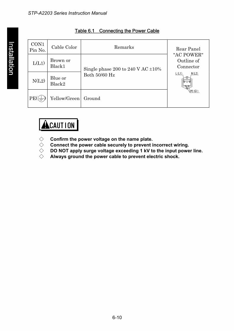
STP-A2203 Series Instruction Manual
Installation stallation
Table 6.1 Connecting the Power CableTable 6.1 Connecting the Power Cable
CON1 Pin No. Cable Color Remarks
L(L1) Brown or Black1
N(L2) Blue or Black2
Single phase 200 to 240 V AC ±10% Both 50/60 Hz
PE( )
Yellow/Green
Ground
Rear Panel
"AC POWER" Outline of Connector
PE( )
N(L2)L(L1)
◇ Confirm the power voltage on the name plate. ◇ Connect the power cable securely to prevent incorrect wiring. ◇ DO NOT apply surge voltage exceeding 1 kV to the input power line. ◇ Always ground the power cable to prevent electric shock.
6-10
STP-A2203 Series Instruction Manual
6.5 Connecting to Semiconductor Equipment
Inst
alla
tion The STP pump is a component system when installing to the semiconductor
equipment. Consider the followings when designing the semiconductor equipment.
6.5.1 Connecting to Power
The STP control unit receives its power from the semiconductor equipment electrical distribution system via a circuit breaker. Electrical energy isolation (Lockout/Tagout) is achieved by opening the main disconnect device or circuit breaker of the semiconductor equipment, thereby: removing power from the STP pump. Provide the equipment with the main disconnect or circuit breaker devices rated for at least 10,000 Arms symmetrical amperes interrupting capacity (AIC).
6.5.2 Emergency Off Circuit (EMO Circuit)
Activation of EMO circuit of the equipment will interrupt electrical power from the STP control unit. When the power is shut off, the STP pump performs the same as a power failure. (After backup operation of a power failure, the rotor lands on the touch down bearing) Consider the followings when establishing the EMO circuit.
◇ Unite the exhaust gas system to prevent atmosphere from being introduced into the STP pump when the EMO circuit operates. (example: shut the valve) When atmosphere is introduced into the STP pump, the touch down bearing may not operate normally.
◇ The STP pump rotates for a while after the EMO circuit shuts off the power. Perform a recovery operation after the STP pump has stopped completely.
◇ Before performing the operation check of the EMO circuit with regular maintenance, stop the STP pump to prevent damage to the touch down bearing.
6-11
STP-A2203 Series Instruction Manual
7 How to Start/Stop the STP Pump
◇ NEVER connect or disconnect any cables while the power is ON. ◇ NEVER turn the primary power OFF (Switch the breaker "OFF") while
the STP pump is in rotation. ◇ DO NOT release the inlet port flange or outlet port flange into the
atmosphere while the STP pump is in rotation.
7.1 Before Starting
Ope
ratio
n
After completing installation, piping, leakage test of the STP pump, installation of the STP control unit, and wiring of cables, the STP pump is ready for start. Check the following items before starting:
1) Are the STP pump and the STP control unit secured according to the appropriate method?
2) Is the power cable connected correctly to the power supply? 3) Is the power voltage selected properly? 4) Are the STP connection cable, and other cables securely connected?
Are each terminal and each connector securely locked? 5) Is the serial number of the STP pump the same as that of the STP control
unit? If they are different, perform the tuning according to Section 9.1, "Tuning."
6) Did you change the STP connection cable length? If you did, perform the tuning by reference to Section 9.1, "Tuning."
7-1
STP-A2203 Series Instruction Manual
7.2 Start Procedures
Start the backing pump before or simultaneously with start of the STP pump. Open the vacuum valve located at the outlet port flange side after starting the backing pump.
◇ DO NOT open the vacuum valve without operating the backing pump. Depending upon the type of the backing pump, doing so may cause a reverse flow of oil, which could contaminate the inside of the STP pump.
Operation
◇ When start/stop operations are frequently performed, the STP pump may overheat. Avoid doing so.
7.3 Stop Procedures
Close the vacuum valve located at the outlet port flange side just before or after stopping the STP pump. After closing the valve, stop the backing pump.
◇ DO NOT stop the backing pump without closing the vacuum valve. Depending upon the type of the backing pump, doing so could cause a reverse flow of atmospheric air into the STP pump, which may result in a malfunction.
◇ DO NOT stop the backing pump without closing the valve. Depending upon the type of the backing pump, doing so may cause a reverse flow of oil, which could contaminate the inside of the STP pump.
7-2
STP-A2203 Series Instruction Manual
There are two methods of operating the STP pump: MANUAL and REMOTE. Select one which fits your vacuum equipment.
7.4 Manual Operation (See Figures 7.1.)
Slide the "MANUAL/REMOTE" changeover switch on the STP control unit front panel to the position opposite to "ON." At this time, the "REMOTE" lamp is off.
Ope
ratio
n
7.4.1 Powering ON
1) Switch "ON" the breaker on the rear panel. (To prevent incorrect operation, a metal fitting is attached to the breaker. Loosen the screw, lift the metal fitting, and secure it.) The magnetic bearing functions and the rotor levitates (POWER ON state). The "POWER" lamp lights.
2) The STP control unit executes the self test. If no error is found, the LCD displays "Levitation." In case of the STP pump with the TMS unit (optional accessory), the "TEMP CTRL" lamp also lights and the TMS unit starts.
7.4.2 Starting the STP Pump
1) Press the "START" switch on the front panel to start and accelerate the STP pump. The "ACCEL." lamp lights. The LCD displays the current rotational speed in "ACCEL: ***00rpm" in units of 500 rpm (ACCELERATION state).
2) When the STP pump attains the rated speed of rotations, the "ACCEL." lamp goes out, and the "NORMAL" lamp lights. Also, the LCD displays "NORMAL: ***00rpm" (NORMAL OPERATION state).
7-3
STP-A2203 Series Instruction Manual
7.4.3 Stopping the STP Pump
1) Press the "STOP" switch on the front panel to stop the STP pump. The "NORMAL" lamp or "ACCEL." lamp goes out, and the "BRAKE" lamp lights (BRAKE state).
2) The "BRAKE" lamp goes out when rotational speed goes below 500 rpm.
7.4.4 Starting the STP Pump after Stopping
Press the "START" switch on the front panel to reaccelerate the STP pump. The STP pump can be reaccelerated even while it is stopping.
Operation
7.4.5 Powering OFF
Switch "OFF" the breaker on the rear panel when all three lamps of "ACCEL.", "NORMAL", and "BRAKE" are off. The magnetic bearing stops, the rotor lands, and the "POWER" lamp goes out (POWER OFF state).
In case of the STP pump with the TMS unit (optional accessory), the "TEMP CTRL" lamp also goes out and the TMS unit stops.
7.4.6 Starting the STP Pump after a Safety Function Operates
A safety function operates when an abnormality/error occurs in the STP pump or peripheral equipment. To restart the STP pump, remove the cause of the abnormality/error after the "BRAKE" lamp goes out, and press the "RESET" switch. The "FAILURE" lamp goes out and the safety function is released (RESET operation). Then, press the "START" switch. For the safety functions and troubleshooting, see Section 11, "Troubleshooting, Maintenance, and Inspections."
7-4
STP-A2203 Series Instruction Manual
7.5 Remote Operation (See Figures 7.1.)
(Read through Section 8, "Remote Input/Output Signal Connector" before use.)
Slide the "MANUAL/REMOTE" changeover switch on the STP control unit front panel to "ON." The "REMOTE" lamp lights.
7.5.1 Powering ON
1) Switch "ON" the breaker on the STP control unit rear panel. (To prevent incorrect operation, a metal fitting is attached to the breaker. Loosen the screw, lift the metal fitting, and secure it.) The magnetic bearing functions and the rotor levitates (POWER ON state). The "POWER" lamp lights.
Ope
ratio
n
2) The STP control unit executes the self test. If no error is found, the LCD displays "Levitation". In case of the STP pump with the TMS unit (optional accessory), the "TEMP CTRL" lamp also lights and the TMS unit starts.
7.5.2 Starting/Stopping the STP Pump
There are two methods of starting/stopping the STP pump. Use one of them.
Table 7.1 Starting/Stopping the STP Pump during Remote Operation (REMOTE X7)
Method Starting the Pump Stopping the Pump
1 1) Short the circuit between (1)-(21) 2) Short the circuit between (3)-(21) for 0.3
seconds or more. However, when inputting this signal simultaneously with switching "ON" the breaker on the rear panel, short the circuit between (3)-(21) for 10 seconds or more.
Open the circuit between (1)-(21).
2 Short the circuit between (1)-(3). In this case, (21) is not used.
Open the circuit between (1)-(3).
7-5
STP-A2203 Series Instruction Manual
7.5.3 Starting the STP Pump after Stopping
Perform the start operation to reaccelerate the STP pump. See Section 7.5.2, "Starting/Stopping the STP Pump." The STP pump can be reaccelerated even while it is stopping.
7.5.4 Powering OFF
Switch "OFF" the breaker on the rear panel when all three lamps of "ACCEL.", "NORMAL", and "BRAKE" are off. The magnetic bearing stops, the rotor lands, and the "POWER" lamp goes out (POWER OFF state).
Operation
In case of the STP pump with the TMS unit (optional accessory), the "TEMP CTRL" lamp also goes out and the TMS unit stops.
7.5.5 Starting the STP Pump after a Safety Function Operates
A safety function operates when an abnormality/error occurs in the STP pump or peripheral equipment. To restart the STP pump, remove the cause of the abnormality/error after the "BRAKE" lamp goes out, and perform the operation shown in Table 7.2. The "FAILURE" lamp goes out and the safety function is released (RESET operation). Then, restart the STP pump. For the safety functions and troubleshooting, see Section 11, "Troubleshooting, Maintenance, and Inspections."
Table 7.2 Reset Operation during Remote Operation (REMOTE X7)
Method Reset Operation
1 Short the circuit between (1)-(22) for 0.3 seconds or more.
7-6
STP-A2203 Series Instruction Manual
7.6 Operating the TMS Unit (For use with the TMS unit only)
7.6.1 Starting/Stoping
Power on the STP pump to automatically start the TMS unit. Power off the STP pump to automatically stop the TMS unit. While the TMS unit is in operation, the "TEMP CTRL" lamp of the STP control unit lights. When STP pump is in the power ON state, the TMS unit operates regardless of the status of the STP control unit. When the STP pump is the malfunction, the TMS unit is stopped.
Ope
ratio
n
7.6.2 Temperature Control
• When the temperature of the STP pump base is lower than the setting value, the TMS heater is turned "ON", and the cooling water valve is turned "OFF" to heat the STP pump.
• When the temperature of the STP pump base is higher than the setting value, the TMS heater is turned "OFF", and the cooling water valve is turned "ON" to cool the STP pump.
The LCD displays the actual temperature of the STP pump base as "TMS TEMP:**℃".
7-7
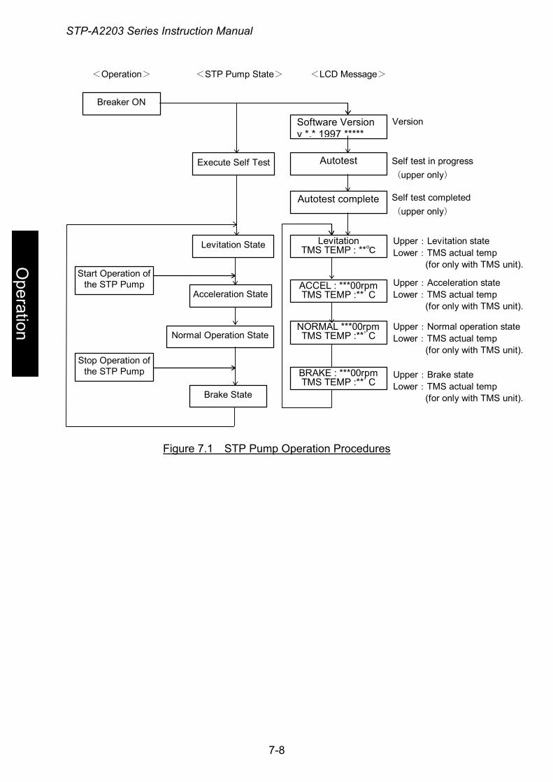
STP-A2203 Series Instruction Manual
Operation
<Operation> <STP Pump State> <LCD Message>
Autotest
Software Versionv *.* 1997 *****
LevitationTMS TEMP : **℃
Autotest complete
BRAKE : ***00rpmTMS TEMP :**゚C
ACCEL : ***00rpmTMS TEMP :**゚C
NORMAL ***00rpmTMS TEMP :**゚C
Upper:Levitation stateLower:TMS actual temp (for only with TMS unit).
Version
Execute Self Test
Levitation State
Breaker ON
Acceleration State
Normal Operation State
Brake State
Self test completed(upper only)
Self test in progress(upper only)
Stop Operation ofthe STP Pump
Start Operation ofthe STP Pump Upper:Acceleration state
Lower:TMS actual temp (for only with TMS unit).
Upper:Normal operation stateLower:TMS actual temp (for only with TMS unit).
Upper:Brake stateLower:TMS actual temp (for only with TMS unit).
Figure 7.1 STP Pump Operation Procedures
7-8
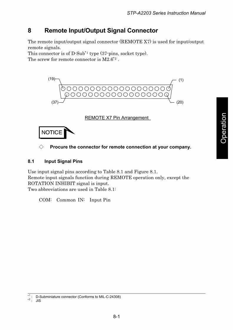
STP-A2203 Series Instruction Manual
8 Remote Input/Output Signal Connector The remote input/output signal connector (REMOTE X7) is used for input/output remote signals. This connector is of D-Sub∗1 type (37-pins, socket type). The screw for remote connector is M2.6∗2 .
(19)
(20)
(1)
(37)
Ope
ratio
n REMOTE X7 Pin Arrangement
◇ Procure the connector for remote connection at your company.
8.1 Input Signal Pins
Use input signal pins according to Table 8.1 and Figure 8.1. Remote input signals function during REMOTE operation only, except the ROTATION INHIBIT signal is input. Two abbreviations are used in Table 8.1:
COM: Common IN: Input Pin
∗1 : D-Subminiature connector (Conforms to MIL-C-24308) ∗2 : JIS
8-1
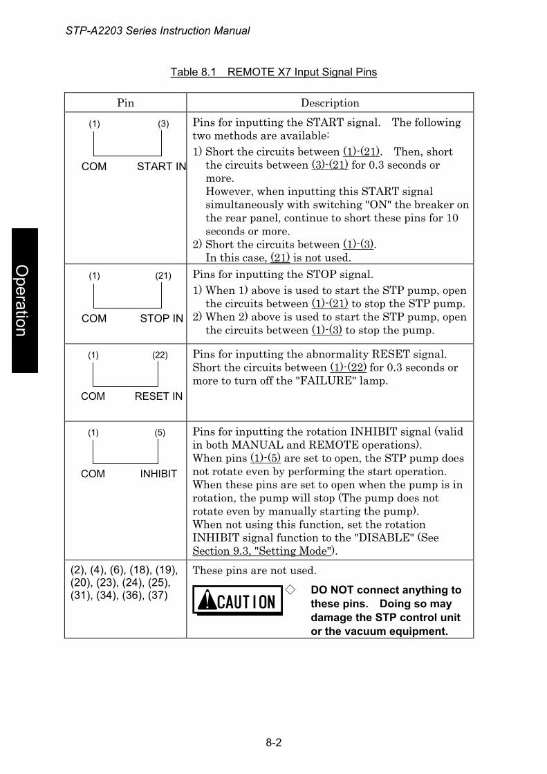
STP-A2203 Series Instruction Manual
Table 8.1 REMOTE X7 Input Signal Pins
Pin Description
COM START IN
(1) (3)
Pins for inputting the START signal. The following two methods are available: 1) Short the circuits between (1)-(21). Then, short
the circuits between (3)-(21) for 0.3 seconds or more. However, when inputting this START signal simultaneously with switching "ON" the breaker on the rear panel, continue to short these pins for 10 seconds or more.
2) Short the circuits between (1)-(3). In this case, (21) is not used.
COM STOP IN
(1) (21)
Pins for inputting the STOP signal. 1) When 1) above is used to start the STP pump, open
the circuits between (1)-(21) to stop the STP pump. 2) When 2) above is used to start the STP pump, open
the circuits between (1)-(3) to stop the pump.
COM RESET IN
(1) (22)
Pins for inputting the abnormality RESET signal. Short the circuits between (1)-(22) for 0.3 seconds or more to turn off the "FAILURE" lamp.
COM INHIBIT
(1) (5)
Pins for inputting the rotation INHIBIT signal (valid in both MANUAL and REMOTE operations). When pins (1)-(5) are set to open, the STP pump does not rotate even by performing the start operation. When these pins are set to open when the pump is in rotation, the pump will stop (The pump does not rotate even by manually starting the pump). When not using this function, set the rotation INHIBIT signal function to the "DISABLE" (See Section 9.3, "Setting Mode"). These pins are not used. (2), (4), (6), (18), (19),
(20), (23), (24), (25), (31), (34), (36), (37) ◇ DO NOT connect anything to
these pins. Doing so may damage the STP control unit or the vacuum equipment.
Operation
8-2
STP-A2203 Series Instruction Manual
Ope
ratio
n
リモート入力信号 / Remote Input Signal
未使用ピンUnused Pins
リセット信号RESET signal
回転禁止信号Rotation INHIBIT signal
START
STOP
RESET
INHIBIT
スタート2)の場合In case of Start 2)
スタート1)の場合In case of Start 1)
Figure 8.1 REMOTE X7 Input Signal Pins
◇ 1 pin (0V) is insulated from the frame ground. ◇ The input current of remote input signal is approx. 5mA. Make
sure the minimum applicable load of the relay contact when the remote operation with the relay.
8-3
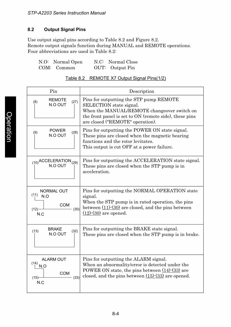
STP-A2203 Series Instruction Manual
8.2 Output Signal Pins
Use output signal pins according to Table 8.2 and Figure 8.2. Remote output signals function during MANUAL and REMOTE operations. Four abbreviations are used in Table 8.2:
N.O: Normal Open N.C: Normal Close COM: Common OUT: Output Pin
Table 8.2 REMOTE X7 Output Signal Pins(1/2)
Pin Description
REMOTEN.O OUT
(8) (27)
Pins for outputting the STP pump REMOTE SELECTION state signal. When the MANUAL/REMOTE changeover switch on the front panel is set to ON (remote side), these pins are closed ("REMOTE" operation).
POWERN.O OUT
(9) (28)
Pins for outputting the POWER ON state signal. These pins are closed when the magnetic bearing functions and the rotor levitates. This output is cut OFF at a power failure.
ACCELERATIONN.O OUT
(10) (29)
Pins for outputting the ACCELERATION state signal. These pins are closed when the STP pump is in acceleration.
(12)
(11)
(30)COM
NORMAL OUT
N.C
N.O
Pins for outputting the NORMAL OPERATION state signal. When the STP pump is in rated operation, the pins between (11)-(30) are closed, and the pins between (12)-(30) are opened.
BRAKEN.O OUT
(13) (32)
Pins for outputting the BRAKE state signal. These pins are closed when the STP pump is in brake.
(15)
(14)
(33)COM
ALARM OUT
N.C
N.O
Pins for outputting the ALARM signal. When an abnormality/error is detected under the POWER ON state, the pins between (14)-(33) are closed, and the pins between (15)-(33) are opened.
Operation
8-4
STP-A2203 Series Instruction Manual
Table 8.2 REMOTE X7 Output Signal Pins(2/2)
Ope
ratio
n
Pin Description
(35)
(16)
(17)COM
AT TEMP.OUT
N.C
N.O
Pins for the TMS unit rated state signal output. When the actual temperature of the TMS unit is within the setting temperature range ±10°C, the pins between (17)-(16) are closed and the pins between (17)-(35) are opened. If the TMS unit function is not valid, the pins do not function. Pins for the emergency vent. valve operation signal. These pins are closed while this valve functions.
L.VALVEN.O OUT
(7) (26)
◇ The emergency vent. valve is not used in this specification. DO NOT use these pins.
8-5
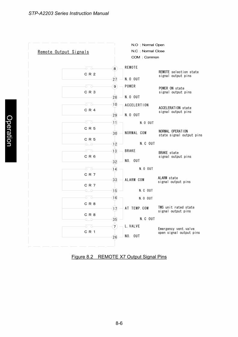
STP-A2203 Series Instruction Manual
Remote Output Signals
8
27
9
28
10
29
11
30
N.O:Normal Open
N.C:Normal Close
COM:Common
N.O OUT
POWER
N.O OUT
N.O OUT
REMOTE selection statesignal output pins
POWER ON statesignal output pins
ACCELERATION statesignal output pins
12
13
32
33
15
14
REMOTE
ACCELERTION
NORMAL COM
N.C OUT
NORMAL OPERATIONstate signal output pins
BRAKE
NO. OUT
CR4
CR5
CR5
CR6
CR7
CR7
ALARM COM
CR3
CR2
N.O OUT
N.O OUT
N.C OUT
16
17
35
7
26
AT TEMP.COM
N.C OUT
L.VALVE
NO. OUT
CR8
CR8
CR1
N.O OUT
BRAKE statesignal output pins
ALARM statesignal output pins
TMS unit rated statesignal output pins
Emergency vent.valveopen signal output pins
Operation
Figure 8.2 REMOTE X7 Output Signal Pins
8-6
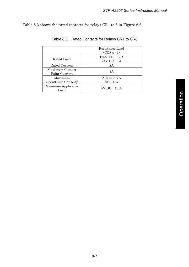
STP-A2203 Series Instruction Manual
Table 8.3 shows the rated contacts for relays CR1 to 8 in Figure 8.2.
Table 8.3 Rated Contacts for Relays CR1 to CR8
Resistance Load (COSφ=1)
Rated Load 125V AC 0.5A 24V DC 1A
Rated Current 2A Maximum Contact
Point Current 1A
Maximum Open/Close Capacity
AC: 62.5 VA DC: 30W
Minimum Applicable Load 5V DC 1mA
Ope
ratio
n
8-7
STP-A2203 Series Instruction Manual
9 Adjustment Methods 9.1 Tuning
For the STP pump, tuning is required to align the position of levitation in the axial direction with the center of the rotor's movable range. Tuning can be performed simply by pressing the "RESET" switch on the front panel. Tuning is completed before delivery, so it is not required before use. However, re-tuning is required in the following cases in which the position of levitation may deviate from the center of the rotor's movable range:
◇ When changing the length of the STP connection cable (not when changing the length of the power cable).
Ope
ratio
n
◇ When changing the combination of the STP pump and the STP control unit (The error message "CAUTION: Bad EEPROM content" is displayed upon performing the self test).
9.1.1 Tuning Method
1) Connect each cable. 2) Switch "ON" the breaker on the rear panel. 3) After the STP pump completes the self test and enters the levitation state or
the error message "CAUTION: Bad EEPROM content" is displayed, set MANUAL/REMOTE changeover switch to the manual and press the "RESET" switch on the front panel for approx. 5 seconds. Tuning starts with "Tuning" displayed on the LCD. When the tunable error message such as "CAUTION:Bad EEPROM content" is displayed, it takes approx. 20 seconds until the display changes "Tuning".
4) Approx. one minute later the LCD displays "Tuning Complete", next it displays "Levitation". This completes the tuning. (When changing the MANUAL/REMOTE changeover switch, set to its setting before tuning.)
◇ DO NOT turn off the primary power (DO NOT switch the breaker "OFF") during tuning. When doing so, perform tuning again. "CAUTION:PCB&Pump EEPROM Failure" may be displayed after powering ON again. When tuning is performed with this message, the setting is initialized. Reconfigure the setting if it has been changed by customer.
9-1
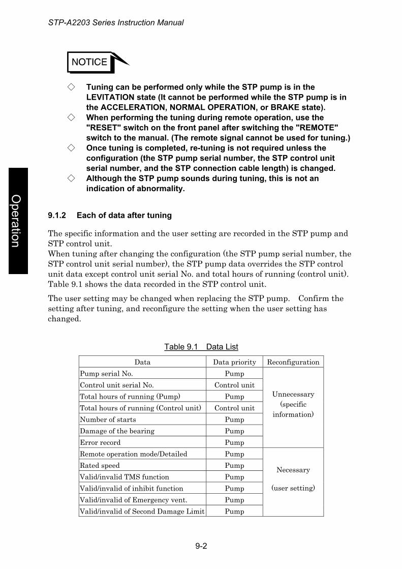
STP-A2203 Series Instruction Manual
◇ Tuning can be performed only while the STP pump is in the LEVITATION state (It cannot be performed while the STP pump is in the ACCELERATION, NORMAL OPERATION, or BRAKE state).
◇ When performing the tuning during remote operation, use the "RESET" switch on the front panel after switching the "REMOTE" switch to the manual. (The remote signal cannot be used for tuning.)
◇ Once tuning is completed, re-tuning is not required unless the configuration (the STP pump serial number, the STP control unit serial number, and the STP connection cable length) is changed.
Operation
◇ Although the STP pump sounds during tuning, this is not an indication of abnormality.
9.1.2 Each of data after tuning
The specific information and the user setting are recorded in the STP pump and STP control unit. When tuning after changing the configuration (the STP pump serial number, the STP control unit serial number), the STP pump data overrides the STP control unit data except control unit serial No. and total hours of running (control unit). Table 9.1 shows the data recorded in the STP control unit. The user setting may be changed when replacing the STP pump. Confirm the setting after tuning, and reconfigure the setting when the user setting has changed.
Table 9.1 Data List
Data Data priority Reconfiguration Pump serial No. Pump Control unit serial No. Control unit Total hours of running (Pump) Pump Total hours of running (Control unit) Control unit Number of starts Pump Damage of the bearing Pump Error record Pump
Unnecessary (specific
information)
Remote operation mode/Detailed Pump Rated speed Pump Valid/invalid TMS function Pump Valid/invalid of inhibit function Pump Valid/invalid of Emergency vent. Pump Valid/invalid of Second Damage Limit Pump
Necessary
(user setting)
9-2
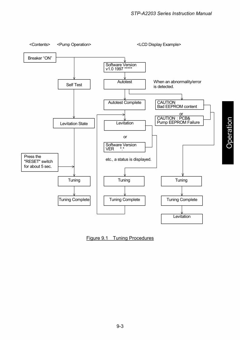
STP-A2203 Series Instruction Manual
<Contents> <Pump Operation> <LCD Display Example>
Autotest
Software Versionv1.0 1997 *****
Self Test
Breaker “ON”
CAUTION Bad EEPROM content
Levitation
Autotest Complete
Software VersionVER *.*
Tuning
Tuning Complete
Levitation State
Press the "RESET" switch for about 5 sec.
Tuning
Tuning Complete
etc., a status is displayed.
or
Tuning
Tuning Complete
Levitation
CAUTION:PCB& Pump EEPROM Failure
or
When an abnormality/error is detected.
O
pera
tion
Figure 9.1 Tuning Procedures
9-3
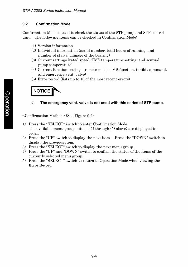
STP-A2203 Series Instruction Manual
9.2 Confirmation Mode
Confirmation Mode is used to check the status of the STP pump and STP control unit. The following items can be checked in Confirmation Mode:
(1) Version information (2) Individual information (serial number, total hours of running, and
number of starts, damage of the bearing) (3) Current settings (rated speed, TMS temperature setting, and acutual
pump temperature) (4) Current function settings (remote mode, TMS function, inhibit command,
and emergency vent. valve) (5) Error record (lists up to 10 of the most recent errors)
Operation
◇ The emergency vent. valve is not used with this series of STP pump.
<Confirmation Method> (See Figure 9.2)
1) Press the "SELECT" switch to enter Confirmation Mode. The available menu groups (items (1) through (5) above) are displayed in order.
2) Press the "UP" switch to display the next item. Press the "DOWN" switch to display the previous item.
3) Press the "SELECT" switch to display the next menu group. 4) Press the "UP" and "DOWN" switch to confirm the status of the items of the
currently selected menu group. 5) Press the "SELECT" switch to return to Operation Mode when viewing the
Error Record.
9-4
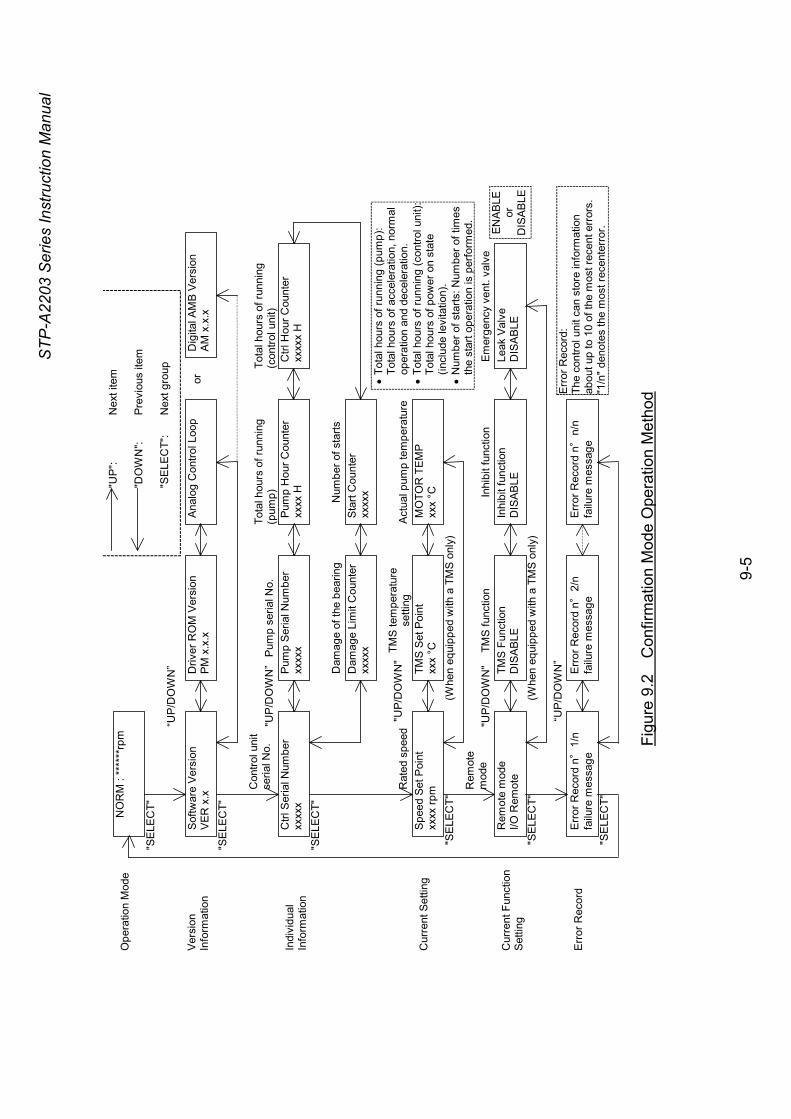
STP-
A220
3 Se
ries
Inst
ruct
ion
Man
ual
Ana
log
Con
trol L
oop
Sof
twar
e Ve
rsio
n V
ER x
.x
Driv
er R
OM
Ver
sion
P
M x
.x.x
Pum
p H
our C
ount
er
xxxx
H
Pum
p S
eria
l Num
ber
xxxx
x C
trl S
eria
l Num
ber
xxxx
x
Dam
age
Lim
it C
ount
erxx
xxx
Dig
ital A
MB
Ver
sion
A
M x
.x.x
MO
TOR
TEM
P
xxx
°C
Spe
ed S
et P
oint
xx
xx rp
m
TMS
Set
Poi
nt
xxx
°C
Inhi
bit f
unct
ion
DIS
AB
LE
Rem
ote
mod
e I/O
Rem
ote
TMS
Fun
ctio
n D
ISA
BLE
Le
ak V
alve
D
ISA
BLE
Err
or R
ecor
d n °
2/n
failu
re m
essa
ge
Err
or R
ecor
d n °
1/n
failu
re m
essa
ge
Err
or R
ecor
d n °
n/n
failu
re m
essa
ge
Ope
ratio
n M
ode
Ver
sion
In
form
atio
n
Indi
vidu
al
Info
rmat
ion
Cur
rent
Set
ting
Cur
rent
Fun
ctio
n
Set
ting
Err
or R
ecor
d
“UP
/DO
WN
”
"UP
/DO
WN
”
"UP/
DO
WN
"
"UP
/DO
WN
"
“UP/
DO
WN
”
"UP"
: N
ext i
tem
"DO
WN
": Pr
evio
us it
em
"SE
LEC
T":
Nex
t gro
up
or
(Whe
n eq
uipp
ed w
ith a
TM
S on
ly)
(Whe
n eq
uipp
ed w
ith a
TM
S on
ly)
NO
RM
: **
****
rpm
"SE
LEC
T"
"SE
LEC
T"
"SE
LEC
T"
"SE
LEC
T"
"SE
LEC
T"
"SE
LEC
T"
Tota
l hou
rs o
f run
ning
(p
ump)
Pu
mp
seria
l No.
Con
trol u
nit
se
rial N
o.
Dam
age
of th
e be
arin
g
Act
ual p
ump
tem
pera
ture
TMS
tem
pera
ture
se
tting
R
ated
spe
ed
Rem
ote
mod
e E
mer
genc
y ve
nt. v
alve
Inhi
bit f
unct
ion
TMS
func
tion
• To
tal h
ours
of r
unni
ng (p
ump)
: To
tal h
ours
of a
ccel
erat
ion,
nor
mal
op
erat
ion
and
dece
lera
tion.
•
Tota
l hou
rs o
f run
ning
(con
trol u
nit):
To
tal h
ours
of p
ower
on
stat
e (in
clud
e le
vita
tion)
. •
Num
ber o
f sta
rts: N
umbe
r of t
imes
th
e st
art o
pera
tion
is p
erfo
rmed
.
Erro
r Rec
ord:
Th
e co
ntro
l uni
t can
sto
re in
form
atio
n ab
out u
p to
10
of th
e m
ost r
ecen
t err
ors.
"1
/n" d
enot
es th
e m
ost r
ecen
terr
or. EN
ABLE
or
DIS
AB
LE
Ctrl
Hou
r Cou
nter
xx
xxx
H
Tota
l hou
rs o
f run
ning
(c
ontro
l uni
t)
Sta
rt C
ount
er
xxxx
x Num
ber o
f sta
rts
Figu
re 9
.2
Con
firm
atio
n M
ode
Ope
ratio
n M
etho
d
9-
5
STP-A2203 Series Instruction Manual
9.3 Parameter Set Mode
Parameter Set Mode is used to set the different parameters of the STP pump and STP control unit. The following items can be set in Parameter Set Mode:
(1) Remote mode (2) Rated speed (3) TMS function enable/disable (4) Inhibit function enable/disable (5) Emergency vent. valve function enable/disable (6) Second Damage Limit function enable/disable (7) Remote mode configuration
Ope
ratio
n
◇ The emergency vent. valve is not used with this series of STP pump.
<Parameter Set Mode> (See Figure 9.3)
1) Push the "SELECT" and "UP" switches at the same time to enter Parameter Set Mode. The available menu items (items (1) through (7) above) are displayed in order.
2) Press the "UP" switch to display the next parameter and the "DOWN" switch to display the previous one.
3) Press the "ENTER" switch to set the parameter to the new setting. 4) Press the "SELECT" switch to display the next item. 5) Change the parameter by pressing the "UP" and "DOWN" switches, then set
it by pressing the "ENTER" switch. 6) When the save screen is displayed, select "YES" then press the "ENTER"
switch to store the new parameters. "IN PROGRESS" is displayed on the LCD followed by "STORAGE OK", when the new parameters have been stored successfully, or "STORAGE NOT OK", when the new parameters have been stored unsuccessfully.
7) Press the "SELECT" switch to return to Operation Mode. Or, do not press any switch for approx. 1 minute and the display will automatically revert to Operation Mode.
8) Select "NO" and press the "SELECT" switch to return to Operation Mode without saving the new parameters.
9-6
STP-A2203 Series Instruction Manual
◇ Do not set the "RS232/485 Modbus" and "LONWORKS" settings of Remote Mode because they cannot be set in the current configuration.
Remote Mode RS232/485 Modbus
Remote Mode I/O Remote
Remote Mode RS232/485 Com
Speed Set Point xxxx rpm
Speed Set Point xxxx rpm
Leak Valve Option DISABLE
Remote Mode LONWORKS
Inhibit Command DISABLE
Inhibit Command ENABLE
TMS Function DISABLE
TMS Function ENABLE
Leak Valve Option ENABLE
"UP" & "SELECT"
Press "SELECT" to go to next menu or "ENTER" to set to new parameter
Press "SELECT" to go to next menu or "ENTER" to set to new parameter
Press "SELECT" to go to next menu or "ENTER" to set to new parameter
Press "SELECT" to go to next menu or "ENTER" to set to new parameter
Press "SELECT" to go to next menu or "ENTER" to set to new parameter
Select Remote Mode
Rated Speed Setting
TMS Function Setting
INHIBIT Function Setting
Emergency vent. valve Setting
"RS232/485 Modbus" and "LONWORKS" cannot be set in the current configuration.
Operation Mode
"UP/DOWN"
"UP/DOWN"
"UP/DOWN"
"UP/DOWN"
"UP/DOWN"
NORM : ******rpm
"UP" Switch :Change to the next value "DOWN" Switch :Change to the previous value "SELECT" Switch :Next menu "ENTER" Switch :Set to new parameter
See next page for details
STORAGE NO
STORAGE YES
Press "SELECT" to go to next menu or "ENTER" to set to new parameter
Not displayed when "I/O Remote"
STORAGE OK
Remote Mode Detail Settings
STORAGE NOT OK
Save Screen
STORAGE IN PROGRESS Saving
Setting Complete
"SELECT"
Successful Unsuccessful
"UP/DOWN"
Press "ENTER" to store the new parameters.
Operation Mode NORM : ******rpm "SELECT"
NORM : ******rpm
"UP" :+500rpm "DOWN" :-500rpm Allowable range:
1/2 rated speed to rated speed
ENABLEor
DISABLE
Second Damage Limit DISABLE
Second Damage Limit ENABLE
Second Damage Limit Setting
Press "SELECT" to go to next menu or "ENTER" to set to new parameter
Ope
ratio
n
Figure 9.3 Parameter Setting Method
9-7
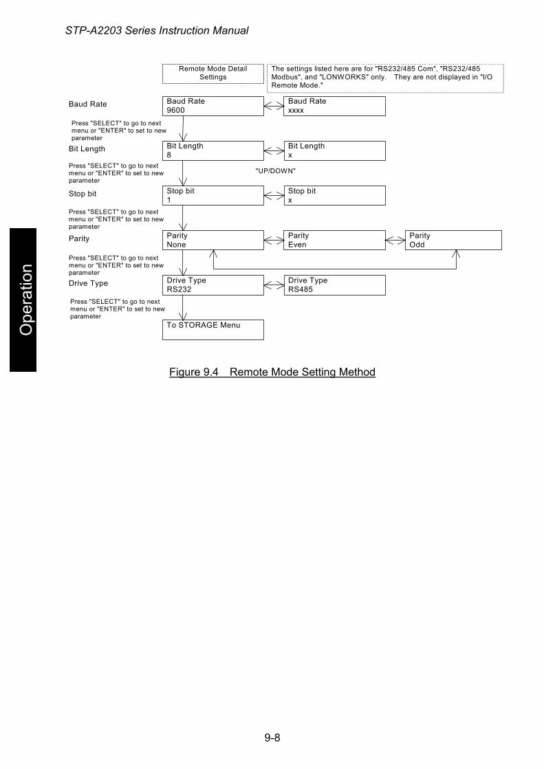
STP-A2203 Series Instruction Manual
Stop bit x
Stop bit 1
Parity Odd
Parity None
Parity Even
Baud Rate 9600
Baud Rate xxxx
Bit Length 8
Bit Length x
Stop bit
Parity
Baud Rate
Bit Length
Drive Type RS485
Drive Type RS232
Drive Type
The settings listed here are for "RS232/485 Com", "RS232/485 Modbus", and "LONWORKS" only. They are not displayed in "I/O Remote Mode."
"UP/DOWN"
Remote Mode Detail Settings
To STORAGE Menu
Press "SELECT" to go to next menu or "ENTER" to set to new parameter
Press "SELECT" to go to next menu or "ENTER" to set to new parameter
Press "SELECT" to go to next menu or "ENTER" to set to new parameter
Press "SELECT" to go to next menu or "ENTER" to set to new parameter
Press "SELECT" to go to next menu or "ENTER" to set to new parameter
Ope
ratio
n
Figure 9.4 Remote Mode Setting Method
9-8
STP-A2203 Series Instruction Manual
10 Safety Functions 10.1 Power Failure
<Ⅰ. Operation at a Power Failure>
When the power voltage drops below 180 V due to a power failure or other, the normal operation of the magnetic bearing is maintained using the regenerative energy of the rotating rotor (backup operation during a power failure).
1) When the rotational speed is 6,000 rpm or more at a power failure: i. The STP control unit detects any power failure of 2 seconds or more and
the STP pump decelerates. At this time, the "POWER" lamp goes out and the "FAILURE" lamp lights. The LCD displays "Mains Failure." Also, an alarm signal is output from REMOTE X7 pins (14)-(33) and (15)-(33). When the rotational speed goes down to approx. 6,000 rpm, the rotor lands on the touch down bearing and stops. The "FAILURE" lamp goes out and the LCD is turned off. Also, the alarm signal output is reset.
ii. The STP control unit does not detect a power failure of less than approx. 2 seconds, continuing rotating the STP pump.
2) When the rotational speed is less than approx. 6,000 rpm at a power failure:
Trou
bles
hoot
ing The STP control unit does not detect the power failure. At this time, the
rotor lands on the touch down bearing and stops.
<Ⅱ. Operation after a Power Recovery>
1) MANUAL operation The magnetic bearing operation and LED lamp and LCD messages are
recovered after a power recovery. The "FAILURE" lamp goes out. • The STP pump continues decelerating even after a power recovery. Press
the "START" switch to reaccelerate the STP pump.
2) REMOTE operation The magnetic bearing operation and LED lamp and LCD messages are
recovered after a power recovery. The "FAILURE" lamp goes out. • When the START signal is input to the REMOTE input pin after a power
recovery, the STP pump reaccelerates. • When the START signal is not input to the REMOTE input pin after the
power recovery, the STP pump continues the BRAKE operation.
10-1
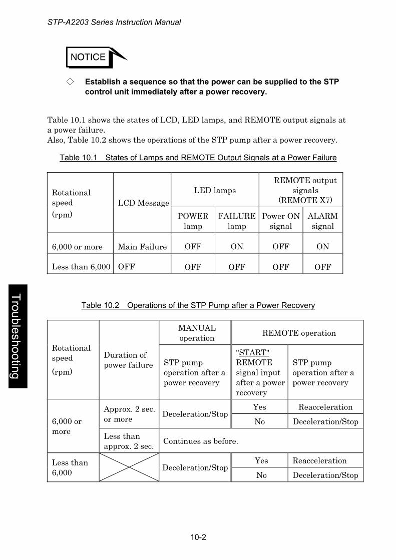
STP-A2203 Series Instruction Manual
◇ Establish a sequence so that the power can be supplied to the STP control unit immediately after a power recovery.
Table 10.1 shows the states of LCD, LED lamps, and REMOTE output signals at a power failure. Also, Table 10.2 shows the operations of the STP pump after a power recovery.
Table 10.1 States of Lamps and REMOTE Output Signals at a Power Failure
LED lamps REMOTE output
signals (REMOTE X7)
Rotational speed (rpm)
LCD Message POWER
lamp FAILURE
lamp Power ON
signal ALARM signal
6,000 or more Main Failure OFF ON OFF ON
Less than 6,000 OFF OFF OFF OFF OFF
Table 10.2 Operations of the STP Pump after a Power Recovery
MANUAL operation REMOTE operation
Rotational speed (rpm)
Duration of power failure STP pump
operation after a power recovery
"START" REMOTE signal input after a power recovery
STP pump operation after a power recovery
Yes Reacceleration Approx. 2 sec. or more Deceleration/Stop
No Deceleration/Stop 6,000 or more Less than
approx. 2 sec. Continues as before.
Yes Reacceleration Less than 6,000 Deceleration/Stop
No Deceleration/Stop
Troubleshooting
10-2
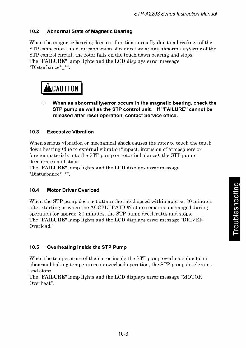
STP-A2203 Series Instruction Manual
10.2 Abnormal State of Magnetic Bearing
When the magnetic bearing does not function normally due to a breakage of the STP connection cable, disconnection of connectors or any abnormality/error of the STP control circuit, the rotor falls on the touch down bearing and stops. The "FAILURE" lamp lights and the LCD displays error message "Disturbance*_*".
◇ When an abnormality/error occurs in the magnetic bearing, check the STP pump as well as the STP control unit. If "FAILURE" cannot be released after reset operation, contact Service office.
10.3 Excessive Vibration
When serious vibration or mechanical shock causes the rotor to touch the touch down bearing (due to external vibration/impact, intrusion of atmosphere or foreign materials into the STP pump or rotor imbalance), the STP pump decelerates and stops. The "FAILURE" lamp lights and the LCD displays error message "Disturbance*_*".
Trou
bles
hoot
ing
10.4 Motor Driver Overload
When the STP pump does not attain the rated speed within approx. 30 minutes after starting or when the ACCELERATION state remains unchanged during operation for approx. 30 minutes, the STP pump decelerates and stops. The "FAILURE" lamp lights and the LCD displays error message "DRIVER Overload."
10.5 Overheating Inside the STP Pump
When the temperature of the motor inside the STP pump overheats due to an abnormal baking temperature or overload operation, the STP pump decelerates and stops. The "FAILURE" lamp lights and the LCD displays error message "MOTOR Overheat".
10-3
STP-A2203 Series Instruction Manual
10.6 Overheating Inside the STP Control Unit
When the temperature inside the STP control unit overheats due to a failure in the air cooling fan, external heat source, and other, the WARNING message "CAUTION: CNT heat1" is displayed. In this case, the STP pump does not stop. If the STP control unit overheats further, the STP pump decelerates and stops. The "FAILURE" lamp lights and the LCD displays error message "CNT Overheat1". If the amplifier inside the STP control unit overheats, the pump decelerates and stops. The "FAILURE" lamp lights and the LCD displays error message "ATMP Failure".
10.7 Overspeed
When the rotational speed of the STP pump exceeds the specified rotational value due to a failure in the motor driver, the breaker in the STP control unit switches "OFF." The STP pump has no power supplied and stops. The "FAILURE" lamp lights and the LCD displays error message "OVERSPEED*".
10.8 Abnormality/Error in the TMS Unit (for Use with the TMS Unit)
Troubleshooting
1) Abnormality/Error in the TMS Unit
i. If the temperature of the STP pump base unit is +10°C higher or -10°C lower than the setting value due to the occurrence of an abnormality/error in the TMS heater or other causes, the STP pump decelerates and stops. Output of the heater and the cooling water unit is OFF. The "FAILURE" lamp lights and the LCD displays error message "TMS Higher Temp." (over +10°C) or "TMS Lower Temp." (below -10°C).
◇ An abnormality/error is not detected even at -10°C or less lower that the setting value within approx. one hour after the STP pump starts.
ii. If an abnormality/error shown in "і" above is not detected and the TMS
heater overheats, the STP pump decelerates and stops. Output of the heater and the cooling water unit is OFF. The "FAILURE" lamp lights and the LCD displays error message "TMS Overheat".
10-4

STP-A2203 Series Instruction Manual
2) Disconnecting of the TMS Connection Cable and Connectors
When an abnormality/error occurs in the TMS connection cable, the STP pump decelerates and stops. Output of the heater and the cooling water unit is OFF. The "FAILURE" lamp lights and the LCD displays error message "T.Cable Disconnect".
Trou
bles
hoot
ing
10-5
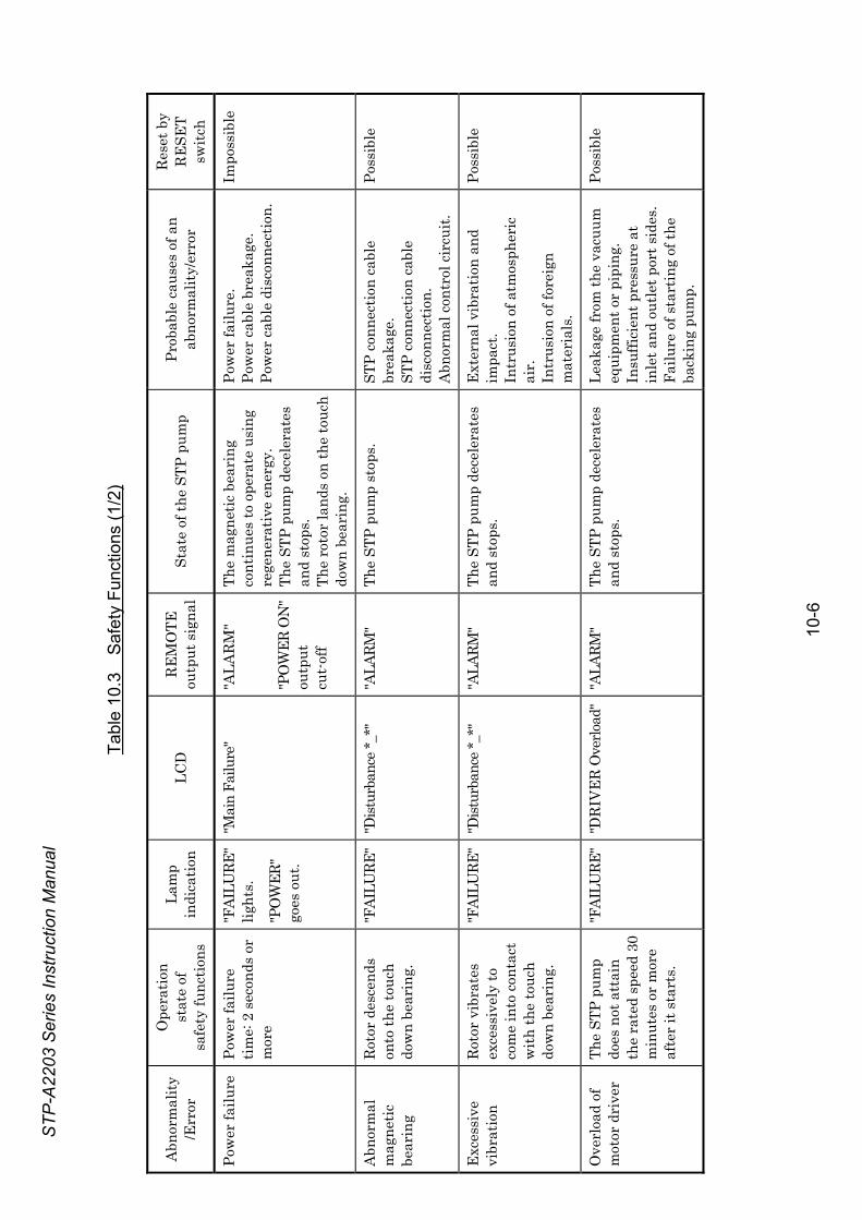
STP-
A220
3 Se
ries
Inst
ruct
ion
Man
ual
Tabl
e 10
.3
Saf
ety
Func
tions
(1/2
)
Abn
orm
ality
/E
rror
Ope
ratio
n
stat
e of
sa
fety
func
tions
Lam
p
indi
catio
n LC
D
RE
MO
TE
outp
ut s
igna
l St
ate
of th
e ST
P pu
mp
Prob
able
cau
ses
of a
n
abno
rmal
ity/e
rror
Res
et b
y
RE
SET
switc
h
Pow
er fa
ilure
Po
wer
failu
re
time:
2 s
econ
ds o
r m
ore
"FAI
LURE
" lig
hts.
"PO
WER
" go
es o
ut.
"Mai
n Fa
ilure
" "A
LAR
M"
"PO
WER
ON
" ou
tput
cu
t-of
f
The
mag
netic
bea
ring
co
ntin
ues
to o
pera
te u
sing
re
gene
rativ
e en
ergy
.
The
STP
pum
p de
cele
rate
s an
d st
ops.
Th
e ro
tor
land
s on
the
touc
h do
wn
bear
ing.
Pow
er fa
ilure
. Po
wer
cab
le b
reak
age.
Po
wer
cab
le d
isco
nnec
tion.
Impo
ssib
le
Abn
orm
al
mag
netic
be
arin
g
Rot
or d
esce
nds
onto
the
touc
h do
wn
bear
ing.
"FAI
LURE
" "D
istur
banc
e *_*
" "A
LARM
" Th
e ST
P pu
mp
stop
s.
STP
conn
ectio
n ca
ble
brea
kage
. ST
P co
nnec
tion
cabl
e di
scon
nect
ion.
A
bnor
mal
con
trol
cir
cuit.
Poss
ible
Exc
essi
ve
vibr
atio
n R
otor
vib
rate
s ex
cess
ivel
y to
co
me
into
con
tact
w
ith th
e to
uch
dow
n be
arin
g.
"FAI
LURE
" "D
istur
banc
e *_*
" "A
LARM
"
The
STP
pum
p de
cele
rate
s an
d st
ops.
E
xter
nal v
ibra
tion
and
impa
ct.
Intr
usio
n of
atm
osph
eric
ai
r.
Intr
usio
n of
fore
ign
mat
eria
ls.
Poss
ible
Ove
rloa
d of
m
otor
dri
ver
The
STP
pum
p do
es n
ot a
ttai
n th
e ra
ted
spee
d 30
m
inut
es o
r m
ore
afte
r it
star
ts.
"FAI
LURE
" "D
RIV
ER
Ove
rload
" "A
LARM
" Th
e ST
P pu
mp
dece
lera
tes
and
stop
s.
Leak
age
from
the
vacu
um
equi
pmen
t or
pipi
ng.
Insu
ffici
ent p
ress
ure
at
inle
t and
out
let p
ort s
ides
. Fa
ilure
of s
tart
ing
of th
e ba
ckin
g pu
mp.
Poss
ible
10
-6
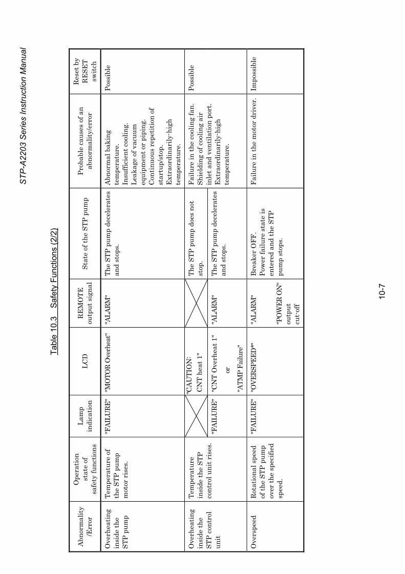
STP-
A220
3 Se
ries
Inst
ruct
ion
Man
ual
Tabl
e 10
.3
Saf
ety
Func
tions
(2/2
)
Abn
orm
ality
/E
rror
Ope
ratio
n
stat
e of
sa
fety
func
tions
Lam
p
indi
catio
n LC
D
RE
MO
TE
outp
ut s
igna
l St
ate
of th
e ST
P pu
mp
Prob
able
cau
ses
of a
n
abno
rmal
ity/e
rror
Res
et b
y
RE
SET
switc
h
Ove
rhea
ting
insi
de th
e ST
P pu
mp
Tem
pera
ture
of
the
STP
pum
p m
otor
ris
es.
"FAI
LURE
" "M
OTO
R O
verh
eat"
"ALA
RM"
The
STP
pum
p de
cele
rate
s an
d st
ops.
A
bnor
mal
bak
ing
tem
pera
ture
. In
suffi
cien
t coo
ling.
Le
akag
e of
vac
uum
eq
uipm
ent o
r pi
ping
. C
ontin
uous
rep
etiti
on o
f st
artu
p/st
op.
Ext
raor
dina
rily
-hig
h te
mpe
ratu
re.
Poss
ible
"C
AU
TIO
N:
CN
T he
at 1
"
The
STP
pum
p do
es n
ot
stop
. O
verh
eatin
g in
side
the
STP
cont
rol
unit
Tem
pera
ture
in
side
the
STP
cont
rol u
nit r
ises
. "F
AILU
RE"
"CN
T O
verh
eat 1
"
or
"ATM
P Fa
ilure
"
"ALA
RM"
The
STP
pum
p de
cele
rate
s an
d st
ops.
Failu
re in
the
cool
ing
fan.
Sh
ield
ing
of c
oolin
g ai
r in
let a
nd v
entil
atio
n po
rt.
Ext
raor
dina
rily
-hig
h te
mpe
ratu
re.
Poss
ible
Ove
rspe
ed
Rot
atio
nal s
peed
of
the
STP
pum
p ov
er th
e sp
ecifi
ed
spee
d.
"FAI
LURE
" "O
VERS
PEED
*"
"ALA
RM"
"PO
WER
ON
" ou
tput
cu
t-of
f
Bre
aker
OFF
.
Pow
er fa
ilure
sta
te is
en
tere
d an
d th
e ST
P pu
mp
stop
s.
Failu
re in
the
mot
or d
rive
r.
Impo
ssib
le
10
-7
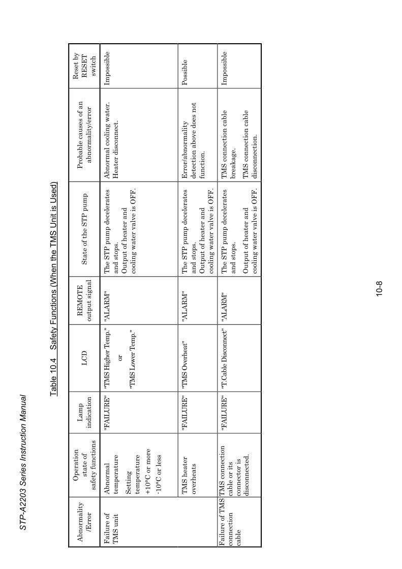
STP-
A220
3 Se
ries
Inst
ruct
ion
Man
ual
10
-8
Tabl
e 10
.4
Saf
ety
Func
tions
(Whe
n th
e TM
S U
nit i
s U
sed)
Abn
orm
ality
/E
rror
Ope
ratio
n
stat
e of
sa
fety
func
tions
Lam
p
indi
catio
n LC
D
RE
MO
TE
outp
ut s
igna
l St
ate
of th
e ST
P pu
mp
Prob
able
cau
ses
of a
n
abno
rmal
ity/e
rror
Res
et b
y
RE
SET
switc
h
Abn
orm
al
tem
pera
ture
Sett
ing
tem
pera
ture
+1
0°C
or
mor
e -1
0°C
or
less
"FAI
LURE
" "T
MS
Hig
her T
emp.
"
or
"TM
S Lo
wer
Tem
p."
"ALA
RM
"
The
STP
pum
p de
cele
rate
s an
d st
ops.
O
utpu
t of h
eate
r an
d co
olin
g w
ater
val
ve is
OFF
.
Abn
orm
al c
oolin
g w
ater
. H
eate
r di
scon
nect
. Im
poss
ible
Fa
ilure
of
TMS
unit
TMS
heat
er
over
heat
s "F
AILU
RE"
"TM
S O
verh
eat"
"ALA
RM
" Th
e ST
P pu
mp
dece
lera
tes
and
stop
s.
Out
put o
f hea
ter
and
cool
ing
wat
er v
alve
is O
FF.
Err
or/a
bnor
mal
ity
dete
ctio
n ab
ove
does
not
fu
nctio
n.
Poss
ible
Failu
re o
f TM
S co
nnec
tion
cabl
e
TMS
conn
ectio
n ca
ble
or it
s co
nnec
tor
is
disc
onne
cted
.
"FAI
LURE
" "T
.Cab
le D
iscon
nect
" "A
LARM
" Th
e ST
P pu
mp
dece
lera
tes
and
stop
s.
Out
put o
f hea
ter
and
cool
ing
wat
er v
alve
is O
FF.
TMS
conn
ectio
n ca
ble
brea
kage
.
TMS
conn
ectio
n ca
ble
disc
onne
ctio
n.
Impo
ssib
le
STP-A2203 Series Instruction Manual
11 Troubleshooting, Maintenance, and Inspection The STP pump is provided with safety functions for various abnormality/errors.
When an abnormality/errors occurs in the pump or control unit, the safety function operates with the "FAILURE" lamp lit, and an alarm signal is output from the remote output pins. An error message showing the number of the error in the form "Error n°**/**" and the contents of the error are displayed alternately on the lower line of the LCD.
If an abnormality/error is found when using the STP pump, check it and take measures in accordance with the following procedures. If you cannot trace it or if the STP pump does not function normally after the troubleshooting, fill in the necessary information in the "Malfunction Information" and fax it to Service office.
11.1 Troubleshooting Immediately after an Abnormality/Error Occurs
11.1.1 Troubleshooting Power Failure
Establish a sequence so that the power can be supplied to the STP control unit immediately after a power recovery.
11.1.2 Troubleshooting Other Abnormality/Error
Refer to Section 7.4.6 and 7.5.5, "Starting the STP Pump after a Safety Function Operates."
Trou
bles
hoot
ing
i. After confirming the "BRAKE" lamp goes out and the STP pump stops, remove the probable cause of the abnormality. When the LCD displays an error message, take the necessary action according to Section 11.2, "When Error Message is Displayed on LCD."
ii. Perform the RESET operation according to turn off the "FAILURE" lamp. iii. Perform the START operation. Check if the STP pump operates
correctly.
◇ When disconnecting cables from the STP pump and/or the STP control unit to perform troubleshooting and take the necessary action, confirm that the STP pump stops, turn OFF the primary power (Switch the breaker "OFF"), then disconnect the cables.
◇ If the RESET operation does not turn off the "FAILURE" lamp, confirm that the STP pump stops, turn OFF the primary power (Switch the breaker "OFF"), then turn ON the primary power again (Switch the breaker "ON").
11-1
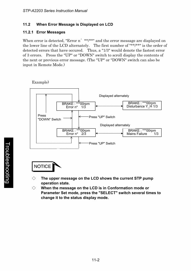
STP-A2203 Series Instruction Manual
11.2 When Error Message is Displayed on LCD
11.2.1 Error Messages
When error is detected, "Error n˚ **/**" and the error message are displayed on the lower line of the LCD alternately. The first number of "**/**" is the order of detected errors that have occured. Thus, a "1/3" would denote the fastest error of 3 errors. Press the "UP" or "DOWN" switch to scroll display the contents of the next or previous error message. (The "UP" or "DOWN" switch can also be input in Remote Mode.)
Example)
Press "DOWN" Switch
BRAKE : ***00rpmError n° 1/3
BRAKE : ***00rpmError n° 2/3
Press "UP" Switch
BRAKE : ***00rpm Disturbance Y_H 1/3
BRAKE : ***00rpm Mains Failure 1/3
Displayed alternately
Press "UP" Switch
Displayed alternately
Troubleshooting
◇ The upper message on the LCD shows the current STP pump operation state.
◇ When the message on the LCD is in Conformation mode or Parameter Set mode, press the "SELECT" switch several times to change it to the status display mode.
11-2
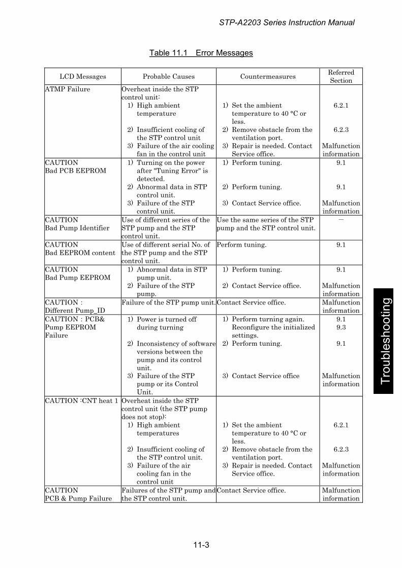
STP-A2203 Series Instruction Manual
Table 11.1 Error Messages
LCD Messages Probable Causes Countermeasures Referred Section
ATMP Failure Overheat inside the STP control unit:
1) High ambient temperature
2) Insufficient cooling of the STP control unit
3) Failure of the air cooling fan in the control unit
1) Set the ambient temperature to 40 °C or less.
2) Remove obstacle from the ventilation port.
3) Repair is needed. Contact Service office.
6.2.1
6.2.3
Malfunction information
CAUTION Bad PCB EEPROM
1) Turning on the power after "Tuning Error" is detected.
2) Abnormal data in STP control unit.
3) Failure of the STP control unit.
1) Perform tuning.
2) Perform tuning. 3) Contact Service office.
9.1
9.1
Malfunction information
CAUTION Bad Pump Identifier
Use of different series of the STP pump and the STP control unit.
Use the same series of the STP pump and the STP control unit.
-
CAUTION Bad EEPROM content
Use of different serial No. of the STP pump and the STP control unit.
Perform tuning. 9.1
CAUTION Bad Pump EEPROM
1) Abnormal data in STP pump unit.
2) Failure of the STP pump.
1) Perform tuning. 2) Contact Service office.
9.1
Malfunction information
CAUTION: Different Pump_ID
Failure of the STP pump unit.Contact Service office. Malfunction information
CAUTION:PCB& Pump EEPROM Failure
1) Power is turned off during turning
2) Inconsistency of softwareversions between the pump and its control unit.
3) Failure of the STP pump or its Control Unit.
1) Perform turning again. Reconfigure the initialized settings.
2) Perform tuning. 3) Contact Service office
9.1 9.3
9.1
Malfunction information
CAUTION :CNT heat 1
Overheat inside the STP control unit (the STP pump does not stop):
1) High ambient temperatures
2) Insufficient cooling of the STP control unit.
3) Failure of the air cooling fan in the control unit
1) Set the ambient temperature to 40 °C or less.
2) Remove obstacle from the ventilation port.
3) Repair is needed. Contact Service office.
6.2.1
6.2.3
Malfunction information
CAUTION PCB & Pump Failure
Failures of the STP pump andthe STP control unit.
Contact Service office. Malfunction information
Trou
bles
hoot
ing
11-3
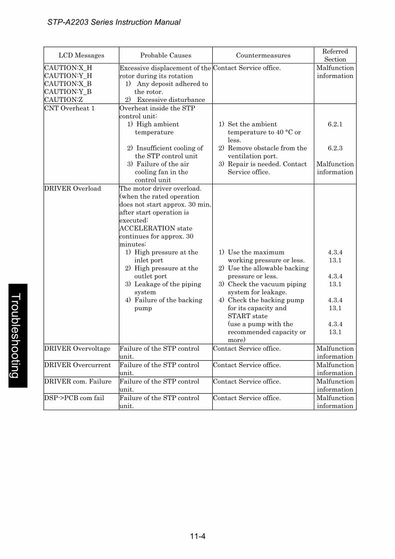
STP-A2203 Series Instruction Manual
Troubleshooting
LCD Messages Probable Causes Countermeasures Referred Section
CAUTION:X_H CAUTION:Y_H CAUTION:X_B CAUTION:Y_B CAUTION:Z
Excessive displacement of the rotor during its rotation
1) Any deposit adhered to the rotor.
2) Excessive disturbance
Contact Service office. Malfunction information
CNT Overheat 1 Overheat inside the STP control unit:
1) High ambient temperature
2) Insufficient cooling of the STP control unit
3) Failure of the air cooling fan in the control unit
1) Set the ambient temperature to 40 °C or less.
2) Remove obstacle from the ventilation port.
3) Repair is needed. Contact Service office.
6.2.1
6.2.3
Malfunction information
DRIVER Overload The motor driver overload. (when the rated operation does not start approx. 30 min. after start operation is executed: ACCELERATION state continues for approx. 30 minutes:
1) High pressure at the inlet port
2) High pressure at the outlet port
3) Leakage of the piping system
4) Failure of the backing pump
1) Use the maximum working pressure or less.
2) Use the allowable backing pressure or less.
3) Check the vacuum piping system for leakage.
4) Check the backing pump for its capacity and START state (use a pump with the recommended capacity or more)
4.3.4 13.1
4.3.4 13.1
4.3.4 13.1
4.3.4 13.1
DRIVER Overvoltage Failure of the STP control unit.
Contact Service office. Malfunction information
DRIVER Overcurrent Failure of the STP control unit.
Contact Service office. Malfunction information
DRIVER com. Failure Failure of the STP control unit.
Contact Service office. Malfunction information
DSP->PCB com fail Failure of the STP control unit.
Contact Service office. Malfunction information
11-4
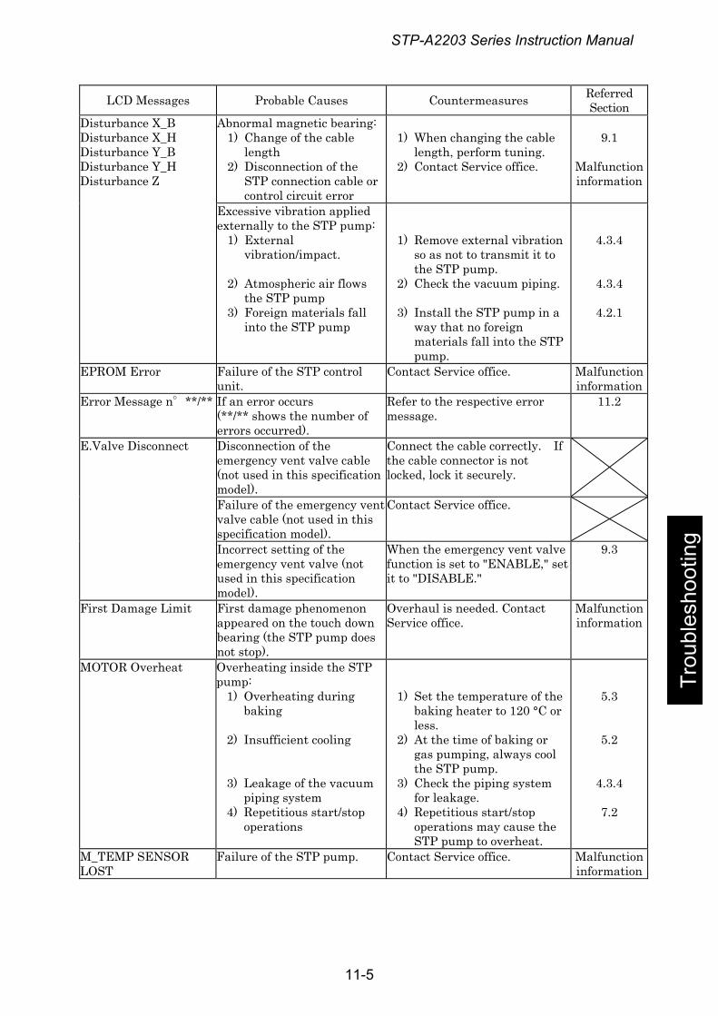
STP-A2203 Series Instruction Manual
Trou
bles
hoot
ing
LCD Messages Probable Causes Countermeasures Referred Section
Disturbance X_B Disturbance X_H Disturbance Y_B Disturbance Y_H Disturbance Z
Abnormal magnetic bearing: 1) Change of the cable
length 2) Disconnection of the
STP connection cable or control circuit error
1) When changing the cable
length, perform tuning. 2) Contact Service office.
9.1
Malfunction information
Excessive vibration applied externally to the STP pump:
1) External vibration/impact.
2) Atmospheric air flows the STP pump
3) Foreign materials fall into the STP pump
1) Remove external vibration so as not to transmit it to the STP pump.
2) Check the vacuum piping.
3) Install the STP pump in a way that no foreign materials fall into the STP pump.
4.3.4
4.3.4
4.2.1
EPROM Error Failure of the STP control unit.
Contact Service office. Malfunction information
Error Message n°**/** If an error occurs (**/** shows the number of errors occurred).
Refer to the respective error message.
11.2
E.Valve Disconnect Disconnection of the emergency vent valve cable (not used in this specification model).
Connect the cable correctly. If the cable connector is not locked, lock it securely.
Failure of the emergency vent valve cable (not used in this specification model).
Contact Service office.
Incorrect setting of the emergency vent valve (not used in this specification model).
When the emergency vent valve function is set to "ENABLE," set it to "DISABLE."
9.3
First Damage Limit First damage phenomenon appeared on the touch down bearing (the STP pump does not stop).
Overhaul is needed. Contact Service office.
Malfunction information
MOTOR Overheat Overheating inside the STP pump:
1) Overheating during baking
2) Insufficient cooling
3) Leakage of the vacuum piping system
4) Repetitious start/stop operations
1) Set the temperature of the baking heater to 120 °C or less.
2) At the time of baking or gas pumping, always cool the STP pump.
3) Check the piping system for leakage.
4) Repetitious start/stop operations may cause the STP pump to overheat.
5.3
5.2
4.3.4
7.2
M_TEMP SENSOR LOST
Failure of the STP pump. Contact Service office. Malfunction information
11-5
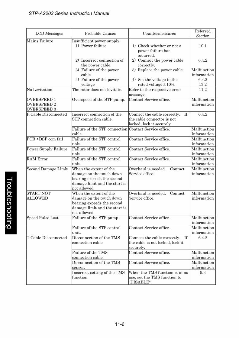
STP-A2203 Series Instruction Manual
Troubleshooting
LCD Messages Probable Causes Countermeasures Referred Section
Mains Failure Insufficient power supply: 1) Power failure
2) Incorrect connection of the power cable.
3) Failure of the power cable
4) Failure of the power voltage
1) Check whether or not a
power failure has occurred.
2) Connect the power cable correctly.
3) Replace the power cable.
4) Set the voltage to the rated voltage±10%.
10.1
6.4.2
Malfunction information
6.4.2 13.2
No Levitation The rotor does not levitate. Refer to the respective error message.
11.2
OVERSPEED 1 OVERSPEED 2 OVERSPEED 3
Overspeed of the STP pump. Contact Service office. Malfunction information
P.Cable Disconnected Incorrect connection of the STP connection cable.
Connect the cable correctly. If the cable connector is not locked, lock it securely.
6.4.2
Failure of the STP connection cable.
Contact Service office. Malfunction information
PCB->DSP com fail Failure of the STP control unit.
Contact Service office. Malfunction information
Power Supply Failure Failure of the STP control unit.
Contact Service office. Malfunction information
RAM Error Failure of the STP control unit.
Contact Service office. Malfunction information
Second Damage Limit When the extent of the damage on the touch down bearing exceeds the second damage limit and the start is not allowed.
Overhaul is needed. Contact Service office.
Malfunction information
START NOT ALLOWED
When the extent of the damage on the touch down bearing exceeds the second damage limit and the start is not allowed.
Overhaul is needed. Contact Service office.
Malfunction information
Speed Pulse Lost Failure of the STP pump. Contact Service office. Malfunction information
Failure of the STP control unit.
Contact Service office. Malfunction information
T.Cable Disconnected Disconnection of the TMS connection cable.
Connect the cable correctly. If the cable is not locked, lock it securely.
6.4.2
Failure of the TMS connection cable.
Contact Service office. Malfunction information
Disconnection of the TMS sensor.
Contact Service office. Malfunction information
Incorrect setting of the TMS function.
When the TMS function is in no use, set the TMS function to "DISABLE".
9.3
11-6
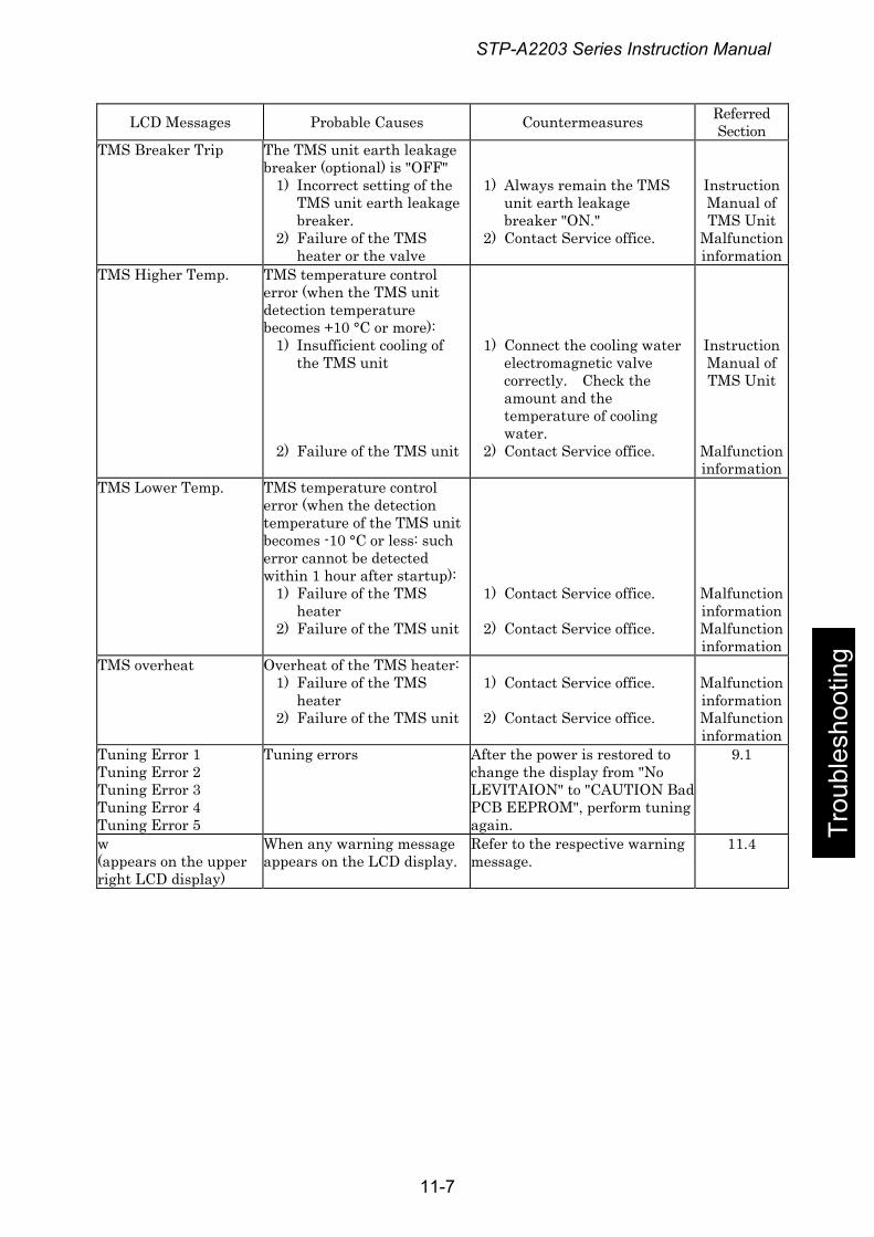
STP-A2203 Series Instruction Manual
Trou
bles
hoot
ing
LCD Messages Probable Causes Countermeasures Referred Section
TMS Breaker Trip The TMS unit earth leakage breaker (optional) is "OFF"
1) Incorrect setting of the TMS unit earth leakage breaker.
2) Failure of the TMS heater or the valve
1) Always remain the TMS unit earth leakage breaker "ON."
2) Contact Service office.
Instruction Manual of TMS Unit
Malfunction information
TMS Higher Temp. TMS temperature control error (when the TMS unit detection temperature becomes +10 °C or more):
1) Insufficient cooling of the TMS unit
2) Failure of the TMS unit
1) Connect the cooling water electromagnetic valve correctly. Check the amount and the temperature of cooling water.
2) Contact Service office.
Instruction Manual of TMS Unit
Malfunction information
TMS Lower Temp. TMS temperature control error (when the detection temperature of the TMS unit becomes -10 °C or less: such error cannot be detected within 1 hour after startup):
1) Failure of the TMS heater
2) Failure of the TMS unit
1) Contact Service office.
2) Contact Service office.
Malfunction information Malfunction information
TMS overheat Overheat of the TMS heater: 1) Failure of the TMS
heater 2) Failure of the TMS unit
1) Contact Service office.
2) Contact Service office.
Malfunction information Malfunction information
Tuning Error 1 Tuning Error 2 Tuning Error 3 Tuning Error 4 Tuning Error 5
Tuning errors After the power is restored to change the display from "No LEVITAION" to "CAUTION BadPCB EEPROM", perform tuning again.
9.1
w (appears on the upper right LCD display)
When any warning message appears on the LCD display.
Refer to the respective warning message.
11.4
11-7
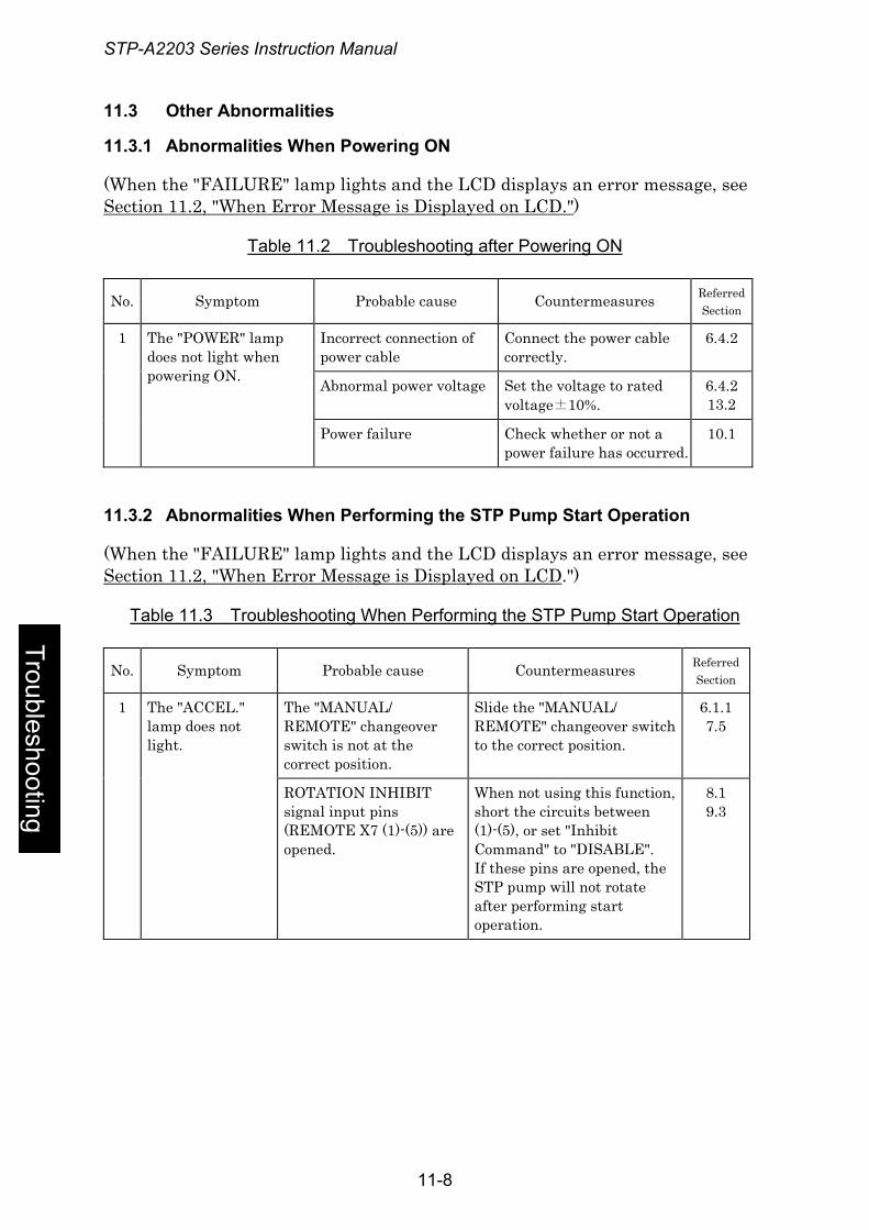
STP-A2203 Series Instruction Manual
11.3 Other Abnormalities
11.3.1 Abnormalities When Powering ON
(When the "FAILURE" lamp lights and the LCD displays an error message, see Section 11.2, "When Error Message is Displayed on LCD.")
Table 11.2 Troubleshooting after Powering ON
No. Symptom Probable cause Countermeasures Referred Section
1 Incorrect connection of power cable
Connect the power cable correctly.
6.4.2
Abnormal power voltage Set the voltage to rated voltage±10%.
6.4.2 13.2
The "POWER" lamp does not light when powering ON.
Power failure Check whether or not a power failure has occurred.
10.1
11.3.2 Abnormalities When Performing the STP Pump Start Operation
(When the "FAILURE" lamp lights and the LCD displays an error message, see Section 11.2, "When Error Message is Displayed on LCD.")
Table 11.3 Troubleshooting When Performing the STP Pump Start Operation
Troubleshooting
No. Symptom Probable cause Countermeasures Referred Section
1 The "ACCEL." lamp does not light.
The "MANUAL/ REMOTE" changeover switch is not at the correct position.
Slide the "MANUAL/ REMOTE" changeover switch to the correct position.
6.1.1 7.5
ROTATION INHIBIT signal input pins (REMOTE X7 (1)-(5)) are opened.
When not using this function, short the circuits between (1)-(5), or set "Inhibit Command" to "DISABLE". If these pins are opened, the STP pump will not rotate after performing start operation.
8.1 9.3
11-8
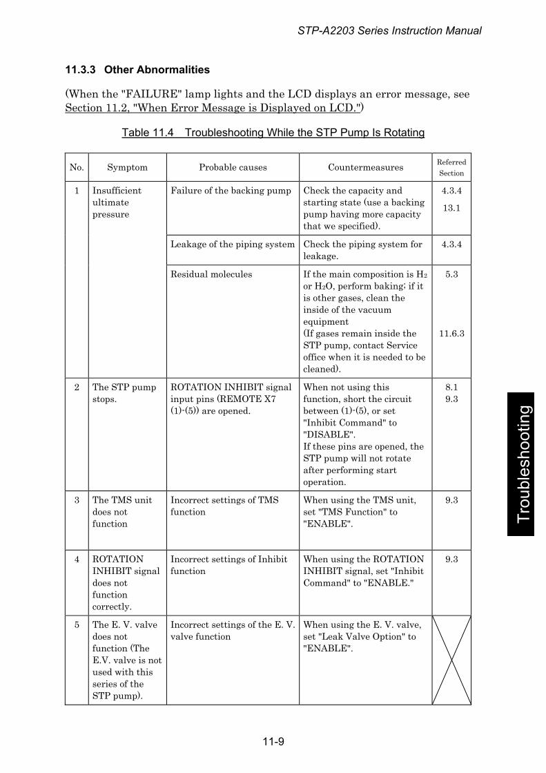
STP-A2203 Series Instruction Manual
11.3.3 Other Abnormalities
(When the "FAILURE" lamp lights and the LCD displays an error message, see Section 11.2, "When Error Message is Displayed on LCD.")
Table 11.4 Troubleshooting While the STP Pump Is Rotating
No. Symptom Probable causes Countermeasures Referred Section
1 Insufficient ultimate pressure
Failure of the backing pump Check the capacity and starting state (use a backing pump having more capacity that we specified).
4.3.4
13.1
Leakage of the piping system Check the piping system for leakage.
4.3.4
Residual molecules If the main composition is H2 or H2O, perform baking; if it is other gases, clean the inside of the vacuum equipment (If gases remain inside the STP pump, contact Service office when it is needed to be cleaned).
5.3
11.6.3
2 The STP pump stops.
ROTATION INHIBIT signal input pins (REMOTE X7 (1)-(5)) are opened.
When not using this function, short the circuit between (1)-(5), or set "Inhibit Command" to "DISABLE". If these pins are opened, the STP pump will not rotate after performing start operation.
8.1 9.3
3 The TMS unit does not function
Incorrect settings of TMS function
When using the TMS unit, set "TMS Function" to "ENABLE".
9.3
4 ROTATION INHIBIT signal does not function correctly.
Incorrect settings of Inhibit function
When using the ROTATION INHIBIT signal, set "Inhibit Command" to "ENABLE."
9.3
5 The E. V. valve does not function (The E.V. valve is not used with this series of the STP pump).
Incorrect settings of the E. V. valve function
When using the E. V. valve, set "Leak Valve Option" to "ENABLE".
Trou
bles
hoot
ing
11-9
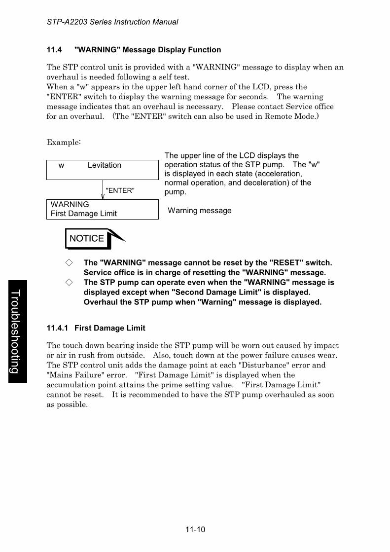
STP-A2203 Series Instruction Manual
11.4 "WARNING" Message Display Function
The STP control unit is provided with a "WARNING" message to display when an overhaul is needed following a self test. When a "w" appears in the upper left hand corner of the LCD, press the "ENTER" switch to display the warning message for seconds. The warning message indicates that an overhaul is necessary. Please contact Service office for an overhaul. (The "ENTER" switch can also be used in Remote Mode.)
Example:
WARNINGFirst Damage Limit
w Levitation
"ENTER"
The upper line of the LCD displays theoperation status of the STP pump. The "w"is displayed in each state (acceleration,normal operation, and deceleration) of thepump.
Warning message
◇ The "WARNING" message cannot be reset by the "RESET" switch. Service office is in charge of resetting the "WARNING" message.
◇ The STP pump can operate even when the "WARNING" message is displayed except when "Second Damage Limit" is displayed. Overhaul the STP pump when "Warning" message is displayed.
Troubleshooting
11.4.1 First Damage Limit
The touch down bearing inside the STP pump will be worn out caused by impact or air in rush from outside. Also, touch down at the power failure causes wear. The STP control unit adds the damage point at each "Disturbance" error and "Mains Failure" error. "First Damage Limit" is displayed when the accumulation point attains the prime setting value. "First Damage Limit" cannot be reset. It is recommended to have the STP pump overhauled as soon as possible.
11-10
STP-A2203 Series Instruction Manual
11.4.2 Second Damage Limit
"Second Damage Limit" is displayed when continuing to operate the STP pump after "First Damage Limit" is displayed, and the accumulation of the damage point attains the second setting value by generating second "Disturbance" or "Mains Failure." Overhaul the STP pump because the STP pump cannot perform the rotational operation when "Second Damage Limit" is displayed.
11.4.3 CAUTION X_H, Y_H, X_B, Y_B, Z
Imbalance of the rotor of the STP pump of is always monitored. Either "CAUTION: X_H", "CAUTION: Y_H", "CAUTION: X_B", "CAUTION: Y_B" or " CAUTION: Z" is displayed when imbalance of the synchronized rotor with the rotational speed exceeds the setting value.
When the deposit accumulates in the STP pump, with the increase of the STP pump operation hours, the rotor balance is lost and the imbalance increases gradually. An increase in the amount of deposit may lead to a malfunction of the STP pump. Perform the overhaul ahead usual case.
11.5 "ERROR RECORD" Message Display Function
The STP control unit can display the contents of up to the last 10 errors on the LCD. To view the error record, push the "SELECT" switch follow the instructions for entering Confirmation Mode in Section 9. The error number of up to the last 10 errors is displayed on the upper line of the LCD in the form "Error Record n°*/*", and the contents of the error is displayed on the lower line. The first number of "**/**" shows the number of the error (the most recent error is number 1) and the second number shows the number of errors that have occurred up to 10. Thus, a "1/3" would denote the most recent error of 3 errors. Press the "UP" or "DOWN" switch to scroll display the contents of the next or previous error in the error record. (The "UP" and "DOWN" switch can also be input in Remote Mode. See Section 9.3 for a more detailed explanation of Confirmation Mode.
Trou
bles
hoot
ing
11-11
STP-A2203 Series Instruction Manual
11.6 Maintenance and Inspection
◇ When performing maintenance and inspections of the STP pump, exhaust gases inside the STP pump thoroughly. Residual gases may cause an accident when removing the STP pump. Confirm the characteristics of gas to be used, referring to the Material Safety Data Sheet (MSDS) you obtain from the gas supplier. Wear personal protective equipment if necessary.
◇ Stop the STP pump, and turn OFF the primary power (Switch the breaker "OFF"), before performing maintenance and inspections of the STP pump and STP control unit. Failure to do so may result in the inadvertent rotation of the STP pump, which may result in an accident.
◇ Do not touch any place other those specified when performing maintenance or inspecting the pump and NEVER open any panel because it could cause shock, malfunction, or short circuit. Troubleshooting
◇ Power OFF the baking heater and other peripheral equipment before performing maintenance and inspections.
◇ The wipes used for clean and decontamination might become hazardous waste depending upon the solvent (alcohol). Dispose of the contaminated wipes appropriately according to the regulations of each national and/or local government.
11-12
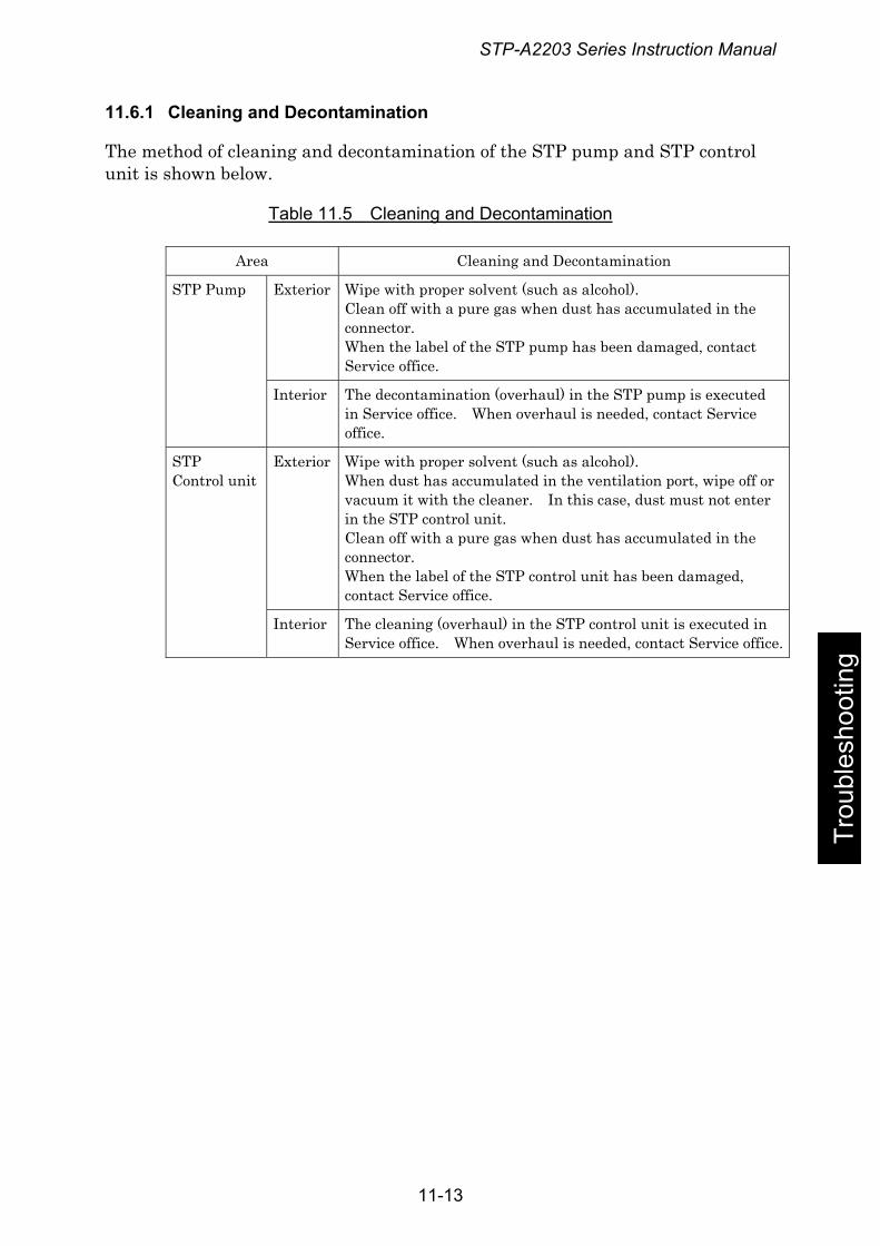
STP-A2203 Series Instruction Manual
11.6.1 Cleaning and Decontamination
The method of cleaning and decontamination of the STP pump and STP control unit is shown below.
Table 11.5 Cleaning and Decontamination
Area Cleaning and Decontamination
Exterior Wipe with proper solvent (such as alcohol). Clean off with a pure gas when dust has accumulated in the connector. When the label of the STP pump has been damaged, contact Service office.
STP Pump
Interior The decontamination (overhaul) in the STP pump is executed in Service office. When overhaul is needed, contact Service office.
Exterior Wipe with proper solvent (such as alcohol). When dust has accumulated in the ventilation port, wipe off or vacuum it with the cleaner. In this case, dust must not enter in the STP control unit. Clean off with a pure gas when dust has accumulated in the connector. When the label of the STP control unit has been damaged, contact Service office.
STP Control unit
Interior The cleaning (overhaul) in the STP control unit is executed in Service office. When overhaul is needed, contact Service office.
Trou
bles
hoot
ing
11-13
STP-A2203 Series Instruction Manual
11.6.2 Inspecting the Deposit
Leaving the STP pump without removing the deposit may cause the STP pump to be corroded beyond repair.
Deposit may have accumulated inside the STP pump depending upon the type of the vacuum equipment installed in the STP pump. An increase in the amount of deposit may lead to a malfunction of the STP pump. Therefore, perform regular maintenance (once every three to six months as a target).
Inspect the inside of the outlet port flange for adhesion of deposit while watching the outlet port flange. If deposit has accumulated to some extent, an overhaul (cleaning) is required. Contact Service office. Note that the costs of troubleshooting problems resulting from deposit will be at your own charge even during the warranty period.
If a problem resulting from deposit occurs inside the STP pump, hermetically seal inlet port, outlet port, purge port, and leak port flanges, and immediately return them to Service office.
For the transport method, see Section 11.8.4, "Transport for Repair or Overhaul."
Troubleshooting
◇ Contact with atmospheric air may cause a reaction of the deposit. DO NOT open the STP pump to atmospheric air as much as possible.
◇ BOC Edwards supplies you the Temperature Management System (TMS) unit to keep the temperature high inside the STP pump and prevent the accumulation of deposit. For details, contact BOC Edwards.
11-14
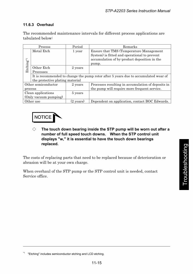
STP-A2203 Series Instruction Manual
11.6.3 Overhaul
The recommended maintenance intervals for different process applications are tabulated below:
Process Period Remarks Metal Etch 1 year Ensure that TMS (Temperature Management
System) is fitted and operational to prevent accumulation of by-product deposition in the pump.
Other Etch Processes
2 years
Etc
hing
*1
It is recommended to change the pump rotor after 5 years due to accumulated wear of the protective plating material
Other semiconductor process
2 years Processes resulting in accumulation of deposits in the pump will require more frequent service.
Clean applications (Only vacuum pumping)
5 years
Other use (2 years) Dependent on application, contact BOC Edwards.
◇ The touch down bearing inside the STP pump will be worn out after a number of full speed touch downs. When the STP control unit displays "w," it is essential to have the touch down bearings replaced.
Trou
bles
hoot
ing
The costs of replacing parts that need to be replaced because of deterioration or abrasion will be at your own charge.
When overhaul of the STP pump or the STP control unit is needed, contact Service office.
*1 "Etching" includes semiconductor etching and LCD etching.
11-15
STP-A2203 Series Instruction Manual
11.6.4 Transporting for Repair or Overhaul
◇ When returning the STP pump which has used any kind of gases to Service office, fill the type of gas and handling precautions in the "Malfunction Information " and fax it to Service office. Confirm the characteristics of gas to be used, referring to the Material Safety Data Sheet (MSDS) you obtain from the gas supplier.
◇ Follow the instruction of "Return Procedure" to prevent an accident during the transportation, repair or overhaul.
◇ When returning the STP pump to Service office, be sure to pack it well to prevent external damage. If "Return Procedure" has not been satisfied, BOC Edwards will not be responsible for any troubles.
i) Always contact Service office before returning the STP pump for repairs, overhaul, or other purposes. To avoid any accident by gases or corrosion inside the STP pump, particularly when corrosive, reactive or flammable gases have been used, ii) Vacuum and hermetically seal the STP pump before transport. iii) Specify the type of gases used and handling precautions in the "Malfunction Information" and return the STP pump to Service office.
Troubleshooting
When returning the STP pump to Service office, be sure to pack it well to prevent external damage. Use similar or superior packaging material as originally supplied.
"Return Procedure" and the "Malfunction Information" are in the end of the Instruction Manual. When additional sheet is needed, contact Service office.
◇ The costs of cleaning and overhaul of the STP pump will be at your own charge.
◇ When returning the STP pump to Service office, fill in the necessary items in the "Malfunction Information " and fax it to Service office.
11-16
STP-A2203 Series Instruction Manual
12 Storage and Disposal 12.1 Storage of the STP Pump
When the STP pump is left unused over a long period (more than a few months), follow the precautions below:
1) Close the inlet port of the STP pump and vacuum it using a backing pump. 2) Introduce dry N2 gas or dry air from the outlet port or the purge port. 3) Close the outlet port and purge port. 4) If the STP pump is water cooled, introduce compressed air from one side of
the cooling water port so that no water remains in the STP pump. 5) Store the STP pump in a vertical position. 6) DO NOT store the STP pump in the following places:
● Place of high humidity. (If it must be stored in a place of high humidity, insulate it from the outside and use a dehumidifying agent.)
● Place of high temperatures (more than + 55 °C) and low temperatures (less than -25 °C).
● Place where there are corrosive gases. ● Place subjected to dripping water. ● Place with a lot of dust. ● Place with insufficient ventilation. ● Place subjected to strong magnetic or electric fields. ● Place subjected to radiation.
Trou
bles
hoot
ing
12.2 Storage of the STP Control Unit
If the STP control unit (including cables) is not used for a long period (more than a few months), follow the precautions below:
1) Store the STP control unit in a horizontal position. 2) DO NOT store the STP control unit in the following places:
● Place of high humidity. (If it must be stored in a place of high humidity, insulate it from the outside and use a dehumidifying agent.)
● Place of high temperature (more than + 55 °C) and low temperature (less than – 25 °C) (excluding the battery).
● Place subjected to direct sunlight. ● Place where there are corrosive gases. ● Place subjected to dripping water. ● Place with a lot of dust. ● Place of insufficient ventilation. ● Place subjected to strong magnetic or electric field. ● Place subjected to radiation. ● Place subjected to mist. ● Place with electric noise. ● Place with vibration.
12-1
STP-A2203 Series Instruction Manual
12.3 Disposal
Dispose of the STP pump and the STP control unit as industrial waste according to the guidelines given by each national and/or local government.
◇ When disposing of the STP pump, exhaust gases inside the STP pump thoroughly. Residual gases may result in an accident when disposing of the STP pump. If the STP pump has been used with reactive or corrosive gasses, always clean thoroughly before disposing of it to avoid any injury. Confirm the characteristics of gas to be used, referring to the Material Safety Data Sheet (MSDS) you obtain from the gas supplier.
◇ BOC Edwards is not responsible for problems during or after disposal.
Troubleshooting
12-2
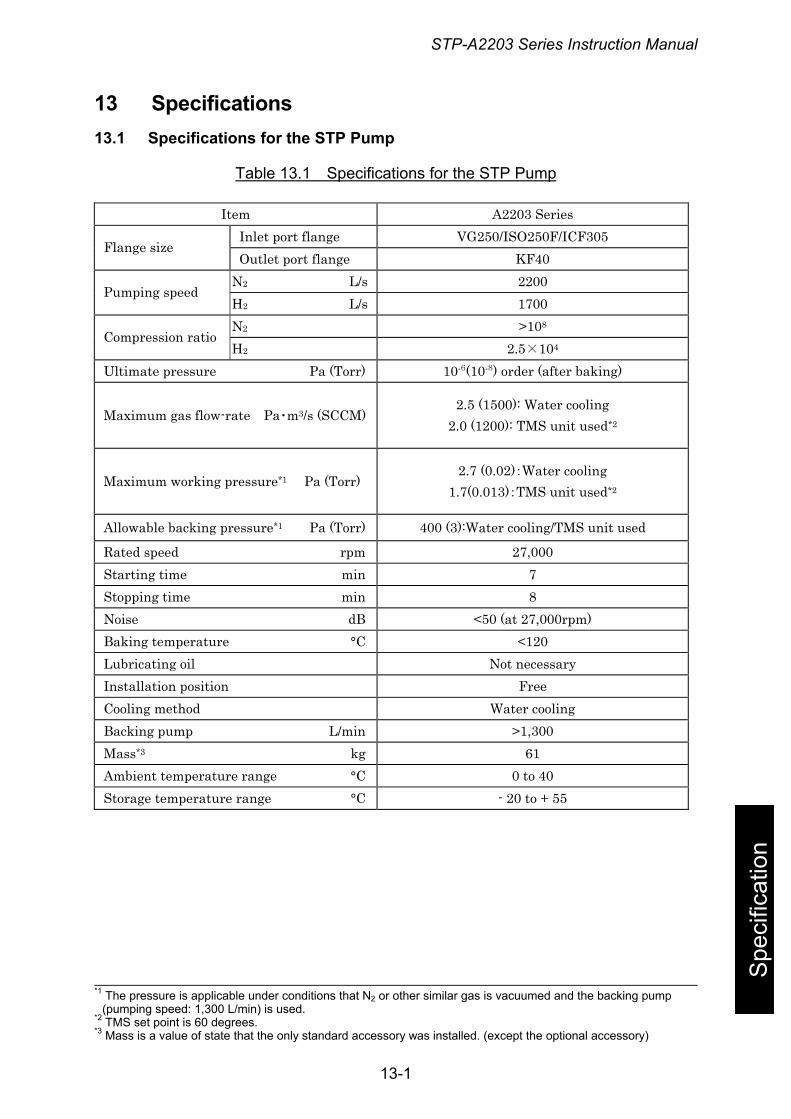
STP-A2203 Series Instruction Manual
13 Specifications 13.1 Specifications for the STP Pump
Table 13.1 Specifications for the STP Pump
Spe
cific
atio
n
Item A2203 Series Inlet port flange VG250/ISO250F/ICF305
Flange size Outlet port flange KF40
N2 L/s 2200 Pumping speed
H2 L/s 1700 N2 >108
Compression ratio H2 2.5×10⁴
Ultimate pressure Pa (Torr) 10-6(10-8) order (after baking)
Maximum gas flow-rate Pa・m3/s (SCCM) 2.5 (1500): Water cooling
2.0 (1200): TMS unit used*2
Maximum working pressure*1 Pa (Torr) 2.7 (0.02):Water cooling
1.7(0.013):TMS unit used*2
Allowable backing pressure*1 Pa (Torr) 400 (3):Water cooling/TMS unit used
Rated speed rpm 27,000 Starting time min 7 Stopping time min 8 Noise dB <50 (at 27,000rpm) Baking temperature °C <120 Lubricating oil Not necessary Installation position Free Cooling method Water cooling Backing pump L/min >1,300 Mass*3 kg 61 Ambient temperature range °C 0 to 40 Storage temperature range °C - 20 to + 55
*1 The pressure is applicable under conditions that N2 or other similar gas is vacuumed and the backing pump (pumping speed: 1,300 L/min) is used.
*2 TMS set point is 60 degrees. *3 Mass is a value of state that the only standard accessory was installed. (except the optional accessory)
13-1
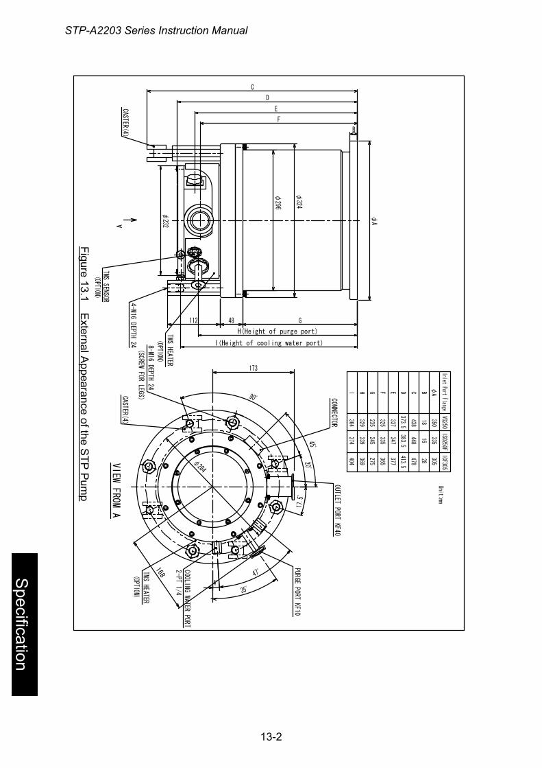
STP-A2203 Series Instruction Manual
A
φ296
φ324
168
4゚
47゚
35゚
173
48112
φ232
4-M16 DEPTH 24
F
E
G
H(Height of purge port)
I(Height of cooling water port)
TMS SENSOR
TMS HEATER
OUTLET PORT KF40
COOLING WATER PORT2-PT 1/4
CASTER(4)
TMS HEATER
8-M16 DEPTH 24
(SCREW FOR LEGS)
CASTER(4)
CONNECTOR
VIEW
FRO
M A 1 7
.5゚
20゚
90゚
45゚
PURGE PORT KF10
C
D
φ284
φA
B
(OPTION)
(OPTION)
(OPTION)
Figure 13.1 External Appearance of the STP Pump
Inlet Port FlangeVG250
ISO250FICF305
φABCDEFGHI
350
18
438
373.5
337
325
235
329
364
335
16
448
383.5
347
335
245
339
374
305
28
478
413.5
377
365
275
369
404
Unit:mm
Figure 13.1 External A
ppearance of the STP
Pum
p
Specification
Figure 13.1 External Appearance of the STP Pump
13-2
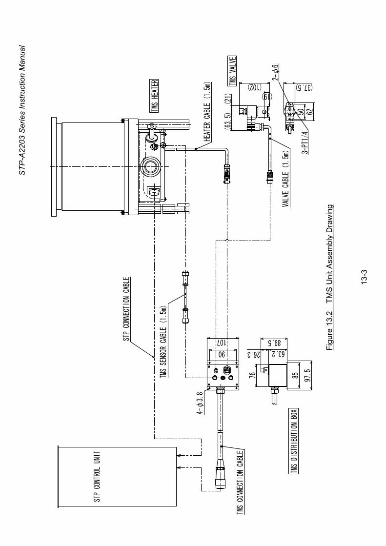
STP-
A220
3 Se
ries
Inst
ruct
ion
Man
ual
TMS
SENS
OR CAB
LE (
1.5m
)
TMS
VALV
E
TMS HE
ATER
STP
CONN
ECTI
ON C
ABLE
TMS DI
STRI
BUTI
ON B
OX
STP CO
NTRO
L UN
IT
TMS CO
NNEC
TION
CAB
LE
HEAT
ER C
ABLE
(1.
5m)
4-φ3.
890
107
76 85 97.5
63.226.3
89.5
(19)(102)
(63.5)
(21)
VALVE
CABLE
(1.5
m) 3-PT1/
4
2-φ
6
(37.5)
50 62
Fi
gure
13.
2 T
MS
Uni
t Ass
embl
y D
raw
ing
13
-3
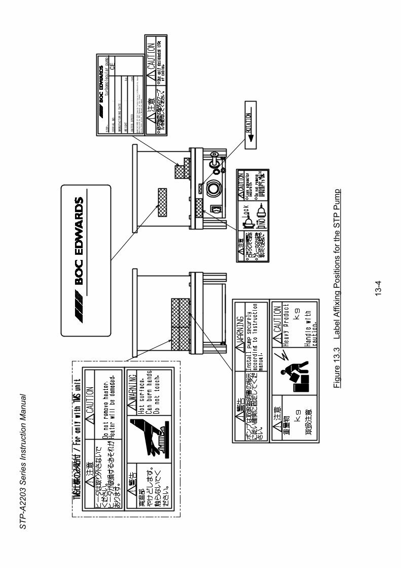
STP-
A220
3 Se
ries
Inst
ruct
ion
Man
ual
turbom
olec
ular
pum
p
SERI
AL N
O
:
MANUFA
CTUR
ING
DATE
:
WEIGHT
:
kg
RATED
SPEE
D
:
rpm
MANUFACTURED BY:BOC Edwards Technologies Ltd.Narashino,Japan
Manufactured by BOC Edwards at the former
Seiko Seiki plant in Narashino,Japan
STP-
CE
Figu
re 1
3.3
Lab
el A
ffixi
ng P
ositi
ons
for t
he S
TP P
ump
13
-4
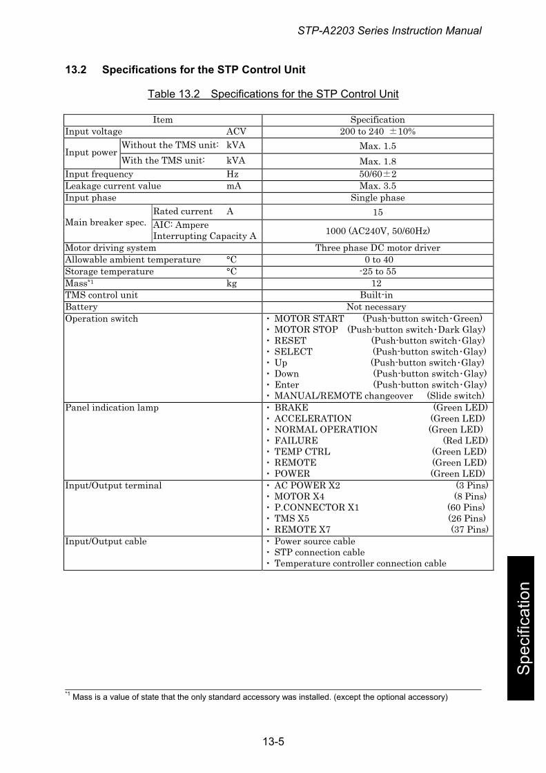
STP-A2203 Series Instruction Manual
13.2 Specifications for the STP Control Unit
Table 13.2 Specifications for the STP Control Unit
Spe
cific
atio
n
Item Specification Input voltage ACV 200 to 240 ±10%
Without the TMS unit: kVA Max. 1.5 Input power With the TMS unit: kVA Max. 1.8
Input frequency Hz 50/60±2 Leakage current value mA Max. 3.5 Input phase Single phase
Rated current A 15 AIC: Ampere Main breaker spec. Interrupting Capacity A 1000 (AC240V, 50/60Hz)
Motor driving system Three phase DC motor driver Allowable ambient temperature °C 0 to 40 Storage temperature °C -25 to 55 Mass*1 kg 12 TMS control unit Built-in Battery Not necessary Operation switch ・ MOTOR START (Push-button switch・Green)
・ MOTOR STOP (Push-button switch・Dark Glay) ・ RESET (Push-button switch・Glay) ・ SELECT (Push-button switch・Glay) ・ Up (Push-button switch・Glay) ・ Down (Push-button switch・Glay) ・ Enter (Push-button switch・Glay) ・ MANUAL/REMOTE changeover (Slide switch)
Panel indication lamp ・ BRAKE (Green LED) ・ ACCELERATION (Green LED) ・ NORMAL OPERATION (Green LED) ・ FAILURE (Red LED) ・ TEMP CTRL (Green LED) ・ REMOTE (Green LED) ・ POWER (Green LED)
Input/Output terminal ・ AC POWER X2 (3 Pins) ・ MOTOR X4 (8 Pins) ・ P.CONNECTOR X1 (60 Pins) ・ TMS X5 (26 Pins) ・ REMOTE X7 (37 Pins)
Input/Output cable ・ Power source cable ・ STP connection cable ・ Temperature controller connection cable
*1 Mass is a value of state that the only standard accessory was installed. (except the optional accessory)
13-5
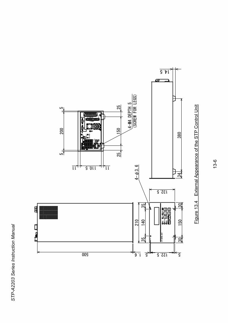
STP-
A220
3 Se
ries
Inst
ruct
ion
Man
ual
4-φ
3.6
4-M
4 DE
PTH
5(SC
REW
FOR
LEGS
)
ON
RESE
TUP
SELECT
DOWN
ENTE
RST
ART
STOP
ACCEL
BRAK
E
POWE
R
TEMP
CTR
L
NORM
AL
FAIL
URE
REMO
TE
122.5
210
132.5
34
380
140
35
35
150
30
30
5 51.6500
14.5
X7 REMOTE
X1P CONNECTOR
MAIN
POW
ER
OFF.
0
ON.1
X
2AC
POWE
R
X3B
X3A
PE
L
(L1)
N(L2)
X4 MOTOR
11110.511
25150
25
5200
5
STP CONTROL
UNIT
Figu
re 1
3.4
Ext
erna
l App
eara
nce
of th
e S
TP C
ontro
l Uni
t
13
-6
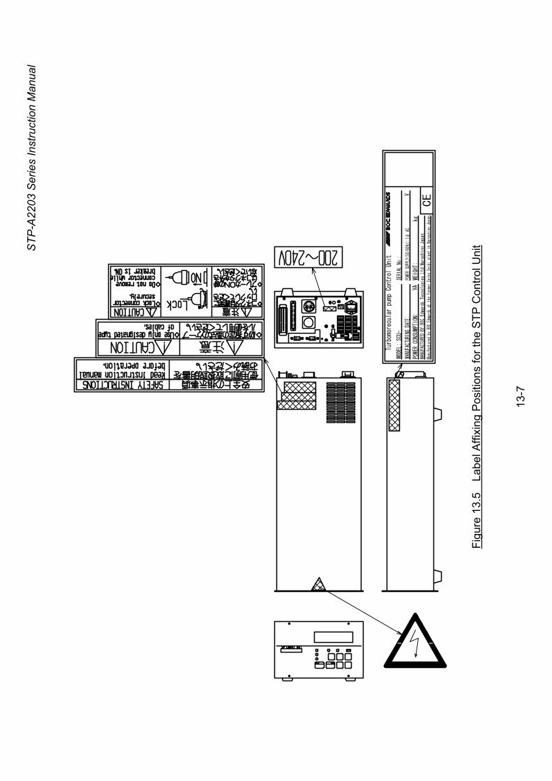
STP-
A220
3 Se
ries
Inst
ruct
ion
Man
ual
Turbomorecul
ar pump Control Un
it
SERI
AL N
o.:
MODE
L: S
CU-
MANU
FACT
URIN
G DA
TE:
POWER
CONS
UMPTIO
N:
POWE
R SU
PPLY
(50/
60Hz
):1φ
AC
WEIG
HT:
kg
V
VA
Manu
fact
ured
by
BOC
Edwa
rds
at t
he f
orme
r Se
iko
Seik
i pl
ant
in N
aras
hino
,Jap
an.
MANU
FACT
URED
BY:
BOC
Edwa
rds
Tecn
olog
ies Lt
d.Na
rash
ino,
Japa
n
CE
Figu
re 1
3.5
Lab
el A
ffixi
ng P
ositi
ons
for t
he S
TP C
ontro
l Uni
t
13
-7
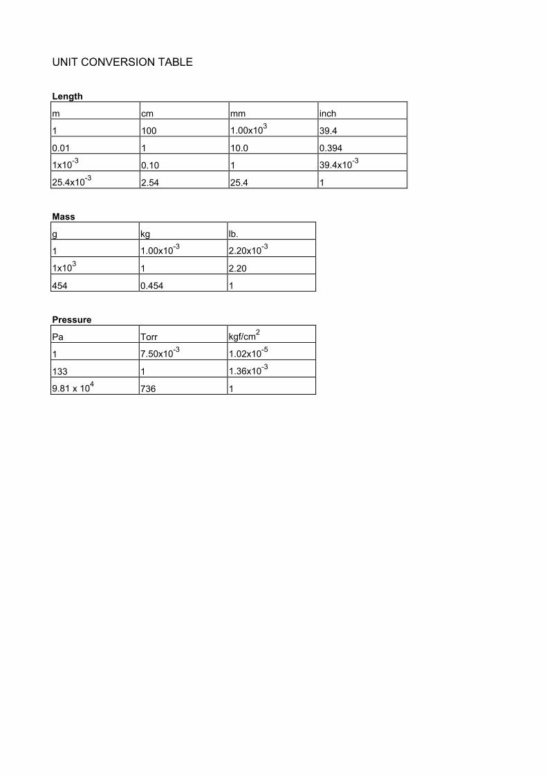
UNIT CONVERSION TABLE Length
m cm mm inch
1 100 1.00x10³ 39.4
0.01 1 10.0 0.394
1x10⁻³ 0.10 1 39.4x10⁻³
25.4x10⁻³ 2.54 25.4 1
Mass
g kg lb.
1 1.00x10⁻³ 2.20x10⁻³
1x10³ 1 2.20
454 0.454 1
Pressure
Pa Torr kgf/cm2
1 7.50x10⁻³ 1.02x10⁻⁵
133 1 1.36x10⁻³
9.81 x 10⁴ 736 1

For more information, contact to the nearest Service Office.
Manufacture: BOC Edwards Japan Limited
2-4-1, Shibakoen, Minato-ku, Tokyo 105-0011 JAPAN Telephone: Domestic 03-5470-6530 International +81-3-5470-6530 Facsimile: Domestic 03-5470-6521 International +81-3-5470-6521
Copyright 2003 BOC Edwards Japan Limited. All rights reserved.
FORM HS1
Return of BOC Edwards Equipment – Procedure
INTRODUCTION Before you return your equipment you must warn BOC Edwards if the substances you used (and produced) in the equipment can be dangerous. This information is fundamental to the safety of our Service Centre employees and will determine the procedures employed to service your equipment. Complete the Declaration (HS2) and send it to BOC Edwards before you dispatch the equipment. It is important to note that this declaration is for BOC Edwards internal use only, and has no relationship to local, national or international transportation safety or environmental requirements. As the person offering the equipment for shipment, it is your responsibility to ensure compliance with applicable laws. GUIDELINES • Your equipment is 'uncontaminated' if it has not been used, or if it has only been used with
substances that are not dangerous/hazardous. Your equipment is 'contaminated' if it has been used with any dangerous/hazardous substances.
• If your equipment has been used with radioactive substances, you must decontaminate it before you return it to BOC Edwards. You must send independent proof of decontamination (for example a certificate of analysis) to BOC Edwards with the Declaration (HS2). Phone BOC Edwards for advice.
• If your equipment is contaminated, you must either: - Remove all traces of contamination (to the satisfaction of the laws governing the
transportation of dangerous/hazardous substances). - Or, properly classify the hazard, mark, manifest and ship the equipment in accordance with
the applicable laws governing the shipment of contaminated/hazardous materials. NOTE: Some contaminated equipment may not be suitable for shipment as airfreight. PROCEDURE 1. Contact BOC Edwards and obtain a Return Authorisation Number for your equipment. 2. Complete the Return of BOC Edwards Equipment – Declaration (HS2). 3. If the equipment is contaminated, you must contact your transporter to ensure that you properly
classify the hazard, mark, manifest and ship the equipment, in accordance with the applicable laws governing the shipment of contaminated/hazardous materials. As the person offering the equipment for shipment, it is your responsibility to ensure compliance with applicable laws. Note: Equipment contaminated with some hazardous materials, such as semiconductor by-products, may not be suitable for shipment as airfreight – contact your transporter for advice.
4. Remove all traces of dangerous gases: pass an inert gas through the equipment and any accessories that will be returned to BOC Edwards. Where possible, drain all fluids and lubricants from the equipment and its accessories.
5. Disconnect all accessories from the equipment. 6. Seal up all of the equipment's inlets and outlets (including those where accessories were
attached) with blanking flanges or, for uncontaminated equipment, with heavy gauge tape. 7. Seal the equipment in a thick polythene/polyethylene bag or sheet. 8. If the equipment is large, strap the equipment and its accessories to a wooden pallet. If the
equipment is too small to be strapped to a pallet, pack it in a suitable strong box. 9. Fax or post a copy of the Declaration (HS2) to BOC Edwards. The Declaration must arrive before
the equipment. 10. Give a copy of the Declaration (HS2) to the transporter. You must tell your transporter if the
equipment is contaminated. 11. Seal the original Declaration in a suitable envelope; attach the envelope securely to the outside of
the equipment package in a clear weather-proof bag. WRITE YOUR RETURN AUTHORISATION NUMBER CLEARLY ON THE OUTSIDE OF THE
ENVELOPE OR ON THE OUTSIDE OF THE EQUIPMENT PACKAGE. P900
-70-
000
Issu
e J
Return of BOC Edwards Equipment - Declaration
Form HS2
You must:
• Know about all of the substances which have been used and produced in the equipment before you complete this Declaration• Read the Return of BOC Edwards Equipment - Procedure (HS1) before you complete this Declaration• Contact BOC Edwards to obtain a Return Authorisation Number and to obtain advice if you have any questions• Send this form to BOC Edwards before you return your equipment
Return Authorisation Number:
Equipment/System Name_____________________________________
Part Number _______________________________________________
Serial Number______________________________________________
Has the equipment been used, tested or operated ?
YES ❏ Go to Section 2 NO ❏ Go to Section 4
IF APPLICABLE:
Tool Reference Number_____________________________________
Process __________________________________________________
Failure Date_______________________________________________
Serial Number ofReplacement Equipment______________________________________
Has the equipment been exposed to substances which are:
• Radioactive (if YES, see Note 1) YES ❏ NO ❏• Biologically active YES ❏ NO ❏• Dangerous to human health and safety? YES ❏ NO ❏
Note 1 : BOC Edwards will not accept delivery of any equipment that is contaminated with radioactive substances, unless you:
• Decontaminate the equipment• Provide proof of decontamination
YOU MUST CONTACT BOC EDWARDS FOR ADVICE BEFORE YOU RETURN SUCH EQUIPMENT
SECTION 1: EQUIPMENT
SECTION 2: SUBSTANCES IN CONTACT WITH THE EQUIPMENT
Print your name:__________________________________________ Print your job title:________________________________________________
Print your organisation:____________________________________________________________________________________________________
Print your address:________________________________________________________________________________________________________
_______________________________________________________________________________________________________________________
Telephone number:_____________________________ Date of equipment delivery: ___________________
I have made reasonable enquiry and I have supplied accurate information in this Declaration. I have not withheld
any information, and I have followed the Return of BOC Edwards Equipment - Procedure (HS1).
Signed: _____________________________________ Date_______________________
• who did you buy the equipment from ? ______________________________________________________________• give the supplier’s invoice number__________________________________________________________________
If you have a warranty claim:
Substance nameChemicalSymbol
Precautions required (for example, use protective gloves, etc.)
Action required after a spill,leak or exposure
Note: Please print out this form, sign it and return the signed form as hard copy.
SECTION 3: LIST OF SUBSTANCES IN CONTACT WITH THE EQUIPMENT
SECTION 4: RETURN INFORMATION
SECTION 5: DECLARATION
P90
0-71
-000
Issu
e J
Reason for return and symptoms of malfunction ________________________________________________________________________________
_______________________________________________________________________________________________________________________

UNITED KINGDOM
CORPORATE HEADQUARTERSBOC EDWARDS Manor RoyalCrawleyWest Sussex RH10 9LWTel +(44) 1293 528844Fax +(44) 1293 533453
BOC EDWARDSWingates Industrial EstateGreat Bank RoadWesthoughton, BoltonLancashireBL5 3SLTel +(44) 1942 652652Fax +(44) 1942 652651
AMERICA (USA)
USA HEADQUARTERSBOC EDWARDSOne Edwards Park301 Ballardvale StreetWilmington, MA 01887Tel +(1) 978 658 5410Toll free (USA only) 1 800 848 9800Fax +(1) 978 658 7969
3901 Burton DriveSanta Clara, CA 95054Tel +(1) 408 496 1177Fax +(1) 408 496 1188
1810 West Drake DriveSuite 101Tempe, AZ 85283Tel +(1) 602 777 7007Fax +(1) 602 777 2244
11701 Stonehollow DriveSuite 100Austin, TX 78758Tel +(1) 512 491 6622Fax +(1) 512 491 0629
3501 Island AvenuePhiladelphia, PA 19153Tel +(1) 215 365 8653Fax +(1) 978 753 6846
BELGIUM
BOC EDWARDSBergensesteenweg 709B1600 Sint-Pieters-LeeuwBrusselsTel +(32) 2 363 0030Fax +(32) 2 363 0064
BRAZIL
BOC DO BRASIL LTDADIVISÃO EDWARDS ALTO VACORua Bernado Wrona 22202710 São Paulo-SPTel +(55) 11 3952 5000Fax +(55) 11 3965 2766
CANADA
BOC EDWARDS5975 Falbourne StreetMississauga, Ontario L5R3W6CanadaTel +(1) 905 501 2558Fax +(1) 905 501 1632
12055 Cote de LiesseDorval, Quebec H9P1B4CanadaTel +(1) 514 631 3501Fax +(1) 514 631 3502
CHINA
BOC TRADING (SHANGHAI) CO. LTD.23 Fu Te Road (N)Wai Gao Qiao Free Trade ZonePudongShanghai, 200131PRC ChinaTel +(86 21) 5866 9618Fax +(86 21) 5866 9993
FRANCE
BOC EDWARDS125 Avenue Louis Roche92238 Gennevilliers, CedexParisTel +(33) 1 47 98 24 01Fax +(33) 1 47 98 44 54
GERMANY
BOC EDWARDSAmmerthalstraße 3685551 KirchheimMunichTel +(49) 89 99 19 18 0Fax +(49) 89 99 19 18 99
HONG KONG S.A.R.
BOC EDWARDS (ASIA)12 Chun Yat StreetTseung Kwan O Industrial EstateTseung Kwan O, KowloonHong Kong S.A.R.Tel +(852) 2372 2640Fax +(852) 2796 9095
INDIA
BOC EDWARDSDIVIN. OF BOC INDIA LIMITED203 Surya Kiran Building19 Kasturba Gandhi MargNew Delhi - 110 001IndiaTel +(91) 11 851 0065Fax +(91) 11 851 0245
ISRAEL
EDWARDS ISRAEL VACUUM LTD.5 Habarzel BlvdGat 2000 Industrial ZoneQiryat Gat 82000Tel +(972) 8 681 0633Fax +(972) 8 681 0640
ITALY
BOC EDWARDSVia Carpaccio 3520090 Trezzano sul NaviglioMilanTel +(39) 02 48 4471Fax +(39) 02 48 401638
JAPAN
HEADQUARTERSBOC EDWARDSShuwa Shiba Park Building A-3F2-4-1 Shibakoen Minato-kuTokyo, 105-0011Tel +(81) (0) 3 5470 6530Fax +(81) (0) 3 5470 6521
KOREA
HEADQUARTERSSONGWON EDWARDS LTD.5th FL. Daewoo Engineering Bldg.Soonae-dongBundang-gu, Sungnam CityKyungki-do, KoreaTel +(82) 31 716 7070Fax +(82) 31 738 1001-3
FACTORY & GVSONGWON EDWARDS LTD.625-7 Upsong-dongChunan CityChungchong Nam-doKoreaTel +(82) 41 621 7070Fax +(82) 41 621 7700
SINGAPORE
BOC EDWARDS (ASIA)42 Loyang DriveLoyang Industrial EstateSingapore 508962Tel +(65) 6546 8408Fax +(65) 6546 8407
TAIWAN, R.O.C.
EDWARDS TECHNOLOGIES LIMITEDNo. 434 Chung hua RoadToufen Town, Miaoli CountyTaiwan ROCTel +(886) 37 611422Fax +(886) 37 611401
http://[email protected]
PLEASE CONTACT ANY OF THESE COMPANIES FOR DETAILS OF OTHER SALES AND SERVICE CENTRES IN YOUR AREA.BOC Edwards is part of BOC Limited. BOC Edwards and the stripe symbol are trade marks of The BOC Group.© BOC Edwards 2003
Produced by Technical Publicity [email protected]
P80
0-80
-000
Issu
e J
01A
09-0
10