Embed Size (px)
Citation preview

INTRODUCTION
Segmental Retaining Walls (SRWs) have progressed from simple landscaping wall solutions used to replace boulder and timber tie retaining walls in the 1980s to one of the major types of mechanically stabilized earth (MSE) walls used in residential commercial and transportation construction around the world In the mid-2000s it was estimated that SRW construction exceeded 300000000 million ft2 (28 M m2) per year
Many walls have been built successfully to heights exceeding 70 ft (21 m) with tech-niques developed since the 1980s In addition the outstanding performance of SRWs under seismic conditions has been proven through research (Research Article Ref 17) and actu-al case studies Recent research (Ref 11 14 15) continues to show that designs using cur-rent established design methodology are very conservative (Allen and Bathurst Ref 2) In AASHTO LRFD Bridge Design Specifica-tions 6th edition 2012 (Ref 1) seismic design is not mandatory for walls with simple geom-etry with seismic accelerations less than 04 g All these referenced documents confirmed the strong performance of SRWs and show how well MSE walls can perform with good quality design materials and construction
Previous NCMA articles have discussed the development of SRWs the dif-ferent types of walls available the changes in the design and specifications (Ref 17 19 20 21 and 22) Recently the Federal Highway Administration (FHWA) introduced the Geosynthetic Reinforced Soil Integrated Bridge Sys-tem (GRS-IBS) system which incorporates SRW units and geosynthetic rein-forcement to build bridge abutment retaining walls This new application with well-known materials is gaining momentum with DOTs across the country
Construction is considered the most critical element as the performance of SRWs is highly depended on the quality of construction Thus the National Concrete Masonry Association (NCMA) continuously develops resources for contractors and educates them in understanding the SRW design considerations and the importance of the recommended SRW construction practices (Ref 17)
This article is intended to discuss all the important elements and provide best practices of SRW construction from the responsibility of parties in a project
site conditions per design materials to construction itself (A poor construction example can be seen on Figure 2)
Figure 1 Geosynthetically Reinforced SoilndashIntegrated Bridge
System (GRS-IBS) Walll
SRW HISTORY ARTICLE SERIES
This is the seventh article in a series of ten articles on the history of segmental retaining walls developed under a grant from the NCMA Education and Research Foundation
SRW History Article Page 1
S E G M E N TA L R E TA I N I N G WA L L C O N S T R U C T I O N
Figure 2 Poor Installation Example (The reinforcement has been installed in the wrong direction the geogrid is not horizontal or taut the geogrid was not installed all the way to the front of the unit and the soil and gravel have not been compacted)
GENERAL
Site Conditions
Site conditions by definitions areA contract clause that typically requires the contractor to at a minimum inspect and understand the grade level and above-ground job site conditions prior to the start of any construction activities The clause may also obligate the contractor to take full responsibility for the sitersquos subsurface conditions (Dictionary of Construc-tioncom 2015)
Before starting the construction process a site review is recommended to verify that existing and proposed finish grades shown on the drawings are in agreement with the topographic information from the project grading plan structures or utilities in the project agree with the information used for the design and are incorporated as they will affect the retaining wall If the site conditions vary from the construction documents then it is recommended to always notify the designer to evaluate a solu-tion and authorize modifications
While above-grade conditions may be obvious from observing the site subgrade conditions may not be evident It is recommended that subsurface investigations be done at the project site to determine soil conditions necessary for design and condi-tions of the subgrade to support the load of the proposed wall It is also a good prac-tice for the geotechnical engineer to discuss the geology of the region and previous use of the property Two areas of concerns should be reported
1 Buried pipes utility trenches and previous use of the site2 Fill zones on the site
When building over buried utilities the utility trenches may not be well compacted resulting in the wall settling The structural performance of the wall may not be compromised but the dip in the wall will be noticeable When building over con-struction fills the soils may not be uniformly compacted and there is a chance that differential settlements or bearing problems may occur The site engineer should note these items in the geotechnical report and give options for correction Proof
rolling of the foundation before placing the leveling pad may identify areas of weak soils or areas that need correction that will have to be reported to the SRW design engineer and to be addressed with the geotechni-cal engineer of the project
Design
The design of the SRWs should be done by a qualified profes-sional In smaller walls or where building codes do not re-quire a design by a profession-al the design may be acquired from design charts provided by the SRW system supplier The
SRW History Article Page 2
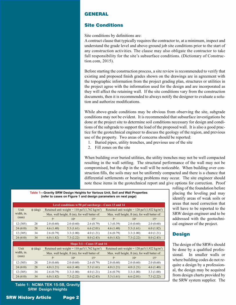
Table 1mdashGravity SRW Design Heights for Various Unit Soil and Wall Properties (refer to cases on Figure 1 and design parameters on next page)
Level conditions w50 psf surchargemdashCases 13 and 14Unit
width in (mm)
φ (deg) Retained unit weight = 110 pcf (1762 kgm3) Retained unit weight = 120 pcf (1922 kgm3)Max wall height ft (m) for wall batter of Max wall height ft (m) for wall batter of
5o 10o 15o 5o 10o 15o
12 (305) 28 20 (060) 20 (060) 26 (079) 13 (039) 20 (060) 20 (060)24 (610) 28 46 (140) 53 (161) 66 (201) 46 (140) 53 (161) 60 (182)12 (305) 34 26 (079) 33 (100) 40 (121) 26 (079) 33 (100) 40 (121)24 (610) 34 60 (182) 73 (222) 80 (243) 60 (182) 73 (222) 80 (243)
Slope 31mdashCases 15 and 16Unit
width in (mm)
φ (deg) Retained unit weight = 110 pcf (1762 kgm3) Retained unit weight = 120 pcf (1922 kgm3)Max wall height ft (m) for wall batter of Max wall height ft (m) for wall batter of
5o 10o 15o 5o 10o 15o
12 (305) 28 20 (060) 20 (060) 26 (079) 20 (060) 20 (060) 20 (060)24 (610) 28 40 (121) 46 (140) 53 (161) 40 (121) 40 (121) 46 (140)12 (305) 34 26 (079) 33 (100) 40 (121) 26 (079) 33 (100) 33 (100)24 (610) 34 60 (182) 73 (222) 80 (243) 53 (161) 66 (201) 73 (222)
Table 1 NCMA TEK 15-5B Gravity SRW Design Heights
contractor should confirm the conditions on the site match the standardized design
Table 1 NCMA TEK 15-5B Gravity SRW Design Heights shows some example design heights for a silty sand soil (ϕ gt 28deg) and a small surcharge above the wall The contractor should be aware the site conditions should match the tables used and that the backfill soils need to be a granular material (clays and silts donrsquot qualify) In the article on SRW Design (Ref 18) and the NCMA Design Manual (Ref 7 8 9) the guidelines for design suggest
bull The maximum design height is around 25 times the depth of the unit (eg a 12 in (300 mm) unit would have a design height of 30 in (762 mm) from the leveling pad for level back slopes no surcharges no water and no front slopes)
bull Maximum spacing between soil reinforcing layers should be 24 in (600 mm) that is normally 2x the unit depth but never exceeding 32 in (800 mm)
bull The minimum length of reinforcing should be 60 of the wall height or 4 ft (12 m) and for pullout extend 1 ft (300 mm) beyond the failure plane or as required by design
Drainage
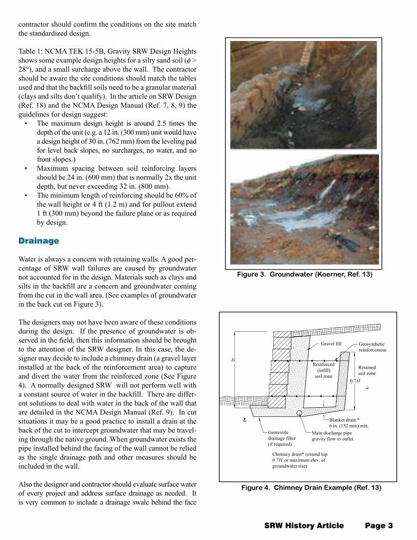
Water is always a concern with retaining walls A good per-centage of SRW wall failures are caused by groundwater not accounted for in the design Materials such as clays and silts in the backfill are a concern and groundwater coming from the cut in the wall area (See examples of groundwater in the back cut on Figure 3)
The designers may not have been aware of these conditions during the design If the presence of groundwater is ob-served in the field then this information should be brought to the attention of the SRW designer In this case the de-signer may decide to include a chimney drain (a gravel layer installed at the back of the reinforcement area) to capture and divert the water from the reinforced zone (See Figure 4) A normally designed SRW will not perform well with a constant source of water in the backfill There are differ-ent solutions to deal with water in the back of the wall that are detailed in the NCMA Design Manual (Ref 9) In cut situations it may be a good practice to install a drain at the back of the cut to intercept groundwater that may be travel-ing through the native ground When groundwater exists the pipe installed behind the facing of the wall cannot be relied as the single drainage path and other measures should be included in the wall
Also the designer and contractor should evaluate surface water of every project and address surface drainage as needed It is very common to include a drainage swale behind the face
SRW History Article Page 3
Figure 3 Groundwater (Koerner Ref 13)
H
Gravel fill
Retained soil zone
Geosynthetic reinforcement
Reinforced (infill)
soil zone
Blanket drain 6 in (152 mm) min
Main discharge pipe gravity flow to outlet
Geotextile drainage filter (if required)
07H
Chimney drain (extend top 07H or maximum elev of groundwater rise)
Figure 4 Chimney Drain Example (Ref 13)
of the wall (see Figure 5) and if necessary a sec-ond swale behind the reinforcement Regardless of the type of wall SRW concrete panel wall or reinforced concrete wall structure not specifically designed for water applications would likely fail by movement or overturning because the waterrsquos hy-drostatic pressure (load increases to about 2 times the original load)
MATERIALS
A good percentage of problems in the field are caused when materials specified are switched intentionally or they change naturally and no longer meet the needed specifications during the construction process Soil changes by far are some of the most common problems and can have the biggest impact in the behavior of the system
Gravel Fill
The gravel fill material is placed inside between and behind the SRW facing units and helps with the compaction close to the SRW units and to evacuate incidental water in that area The recommend material for this area is a well-draining clean crushed stone The NCMA specifications are shown in Table 1
Table 1 Gravel FillGravel fill shall be a clean crushed stone or granular fill meeting the following gradation as determined in accordance with ASTM D 422 (Ref 24)
Sieve Size Percent Passing1 in 100
34 in 75 - 100No 4 0 - 60No 40 0 - 50No 200 0 - 5
Note the percent fines (Sieve size lt No 200) is less than 5
The leveling pad may be constructed with the gravel fill or with a crushed stone base material depending on the drainage needs in the wall
Reinforced Fill
The reinforced fill is a compacted structural fill placed behind soil-reinforced SRW units to the tail end of the reinforcement placed behind the wall The NCMA specifications recommend backfill materials with no more than 35 fines and or-ganic materials are not allowed
SRW History Article Page 4
Figure 5 Drainage Swale Used forSurface Drainage (Ref 9)
Drainage swale (optional)
Cap unit (optional)
SRW unit
Topsoil 8 in (203 mm)
Compacted infill soil Gravel fill
Completed Gravity SRW
Compacted over-excavated material
SRW History Article Page 5
Table 2 Reinforced FillSieve Size Percent Passing
1 in 100No 4 20 - 100No 40 0 - 60No 200 0 - 35
The plasticity index of the fine fraction of the reinforced soil (PI) shall be less than 20 tested in accordance to ASTM D4318 Standard Test Methods for Liquid Limit Plastic Limit and Plasticity Index of Soils (Ref 4) taller applications may require PI lt 5 to 10
Transportation specifications require no more than 15 fines and PIlt 6
Authors Berg (Ref 6) and Koerner (Ref 13) recommend that this specification be converted to a more free drain-ing fill to reduce the likelihood of problems in the wall NCMA (Ref 9) has shown that walls can be built with high fines content soil and perform well even when they were designed to fail (the walls in the Geocomp study were de-signed to fail under hydrostatic load but did not fail struc-turally) Figure 6 NCMA Test Wall Gradation shows the gradation of the soil used in the NCMA test Wall Y with 60 passing the No 200 sieve (almost double the NCMA recommendation on fines content) and the control Wall X There was more movement in the segmental retaining wall Y than was noted in the walls with better fill materials (Wall X) but it still performed well When fine grained soils are used drainage and compaction must be addressed specifi-cally The use of clay fines should be avoided
CONSTRUCTION
Compaction
Due to the nature of the SRW systems compaction is a very important part in the construction process to increase den-sity and soil strength and reduce the settlement in the soil The compaction is achieved by applying a load (energy) to the soil placed in adequate lifts The soil strength proper-ties are a function of density ie a loose soil is weaker than a dense soil Settlement is caused when the soil compresses under its own weight or its own weight plus any surcharge load to form a more dense structure A well compacted fill soil could settle anywhere between 05 to 1 of its total height (ie a 10 ft (3 m) wall could experience 34 in (20 mm) to 15 in (40 mm) settlement) under self-weight A loose soil will settle much more causing serious problems that could lead to the failure of the wall
NCMA recommends placing the fill in 6 to 8 in (152 to 203 mm) lifts compacting each lift to meet the specified densities usually equivalent to a minimum 95 of standard proctor density (ASTM D698 Ref 17) Only hand-oper-ated compaction equipment should be allowed within 3 ft (914 mm) of the back of wall face preferably a vibrating plate compactor with a minimum weight of 250 lb (113 kg) if smaller equipment is used lift heights may need to be smaller to reach the specified densities
Poor compaction practices such as the increase in the lift thickness or not compacting at all to speed construction (see Figure 2) causes big settlements in the fill (ie some walls have shown between 3 to 5 in partially compact-ed walls see Figure 7) not compacting behind the SRW
Figure 6 NCMA Test Wall Gradation (Ref 11)
Settlement
Tension crack
Retained soil(fine grained)
Reinforced soil(fine grained)
Figure 7 Failure Due to Poor Compaction behind the Reinforcement
SRW History Article Page 6
units may also cause downdrag of the geogrid (see Figure 8)
Another observed problems are the outward movement of the facing caused by the use of big equipment too close to the wall face and the development of a tension crack be-hind the reinforcement due to the lack of compaction in the area that ultimately will allow for damaging water to infiltrate
Compaction Testing
Compaction testing is used to verify that the soils are being placed meet the density specified The compaction equipment used has limitations and the reader must be aware that the compaction testing only verifies the density of the soils at the surface (6 in (150 mm) to 8 in (200 mm)) If thicker lifts are proposedused the testing agency should dig down and test the bottom portion of the fill lift Another technique that may cause issues later is the practice of only testing in the back of the reinforced zone where big equipment is used we must emphasize that the compaction require-ments are the same for all regions in the wall regardless of the compaction equip-ment used Please note we do not recommend fill and compaction lifts of over 8 in (200 mm) in any case
A good practice in soil placement is to place the first 8 in (200 mm) lift and make about three passes with the compaction equipment over the soil Compaction test-ing is performed and if the fill passes then this procedure is used for the rest of the construction If the test does not pass more passes will be necessary or a thinner lift thickness until consistent passing results are obtained Further compaction testing during construction confirms the procedure established is valid and verifies require-ments of the specification it does not confirm the whole soil fill is placed to specifi-cation requirements Remember that this procedure is only applicable if there are no changes in the material equipment and moisture conditions
Fill Placement
We have spoken about fill placement in the preceding paragraphs but it cannot be emphasized enough for good performance The fills should be placed in 6 in (150 mm) to 8 in (200 mm) lift thicknesses or less if the equipment is small The fill should be placed from the wall face proceeding backward toward the tail of the soil reinforcement and compacted parallel to the facing from the front of the wall to the tail of the reinforcement By placing fills in this manner the soil reinforcing is tensioned the SRW-geogrid connection is engaged as the slack is pushed toward the tail
We know that the soil fill will settle under its own weight anywhere between 05 to 1 of the wall height The NCMA Design Manual recommends a gravel fill zone behind the SRW units to create a transition between the rigid uncompressible face and the soil (See Figure 8 ) This zone provides drainage at the face but more importantly it is a stiffer layer that reduces compaction effort necessary to compact well at the face and reduces the amount of drag down at the face that potentially lead to performance problems
Figure 8 Drag-down on SRW Reinforced Walls
Concrete Block
Gravel Fill
Compressible Soil
Downdrag movement
SRW with Gravel Fill SRW without Gravel Fill
Reinforcement layer Reinforcement
layer
Concrete Block
Compressible Soil
SRW History Article Page 7
Compaction Loading
Compaction loading on the wall is not verified specifically by NCMA or by the transportation markets but it is indirect-ly addressed by specifying that ldquoheavy compaction equip-ment shall not be used closer than 3 ft (1 m) from the wallrdquo Why Because if large compaction equipment is used the wall face will lean forward whether it is an SRW facing a concrete panel facing or a rigid reinforced concrete wall compaction forces can be large and each system has differ-ent limitations
The US Army Corps of Engineers has addressed compac-tion loading in their design manual DM7 (Ref 16) Figure 9 Compaction Stresses shows the relationship of horizontal loading to the location can compaction effort of the equip-ment used While designers use the dotted line (active earth pressure line) in design and calculations the contractor has to deal with the solid line during construction How does the contractor deal with the loading
bull Move the compaction equipment back further from wall
bull Use a larger stone fill area orbull Reduce or eliminate compaction at the face
Table 3 FS for Overturning by Compaction for 2 ft (600 mm) Lifts
Overturning on a 2 ft (600 mm) Compaction HightMo = 205 ft lbfMr = 225 ft lbf
FSot = 110
Table 4 FS for Overturning with 16 in (406 mm) Lifts
Overturning on a 16 in (406 mm) Compaction HightMo = 121 ft lbfMr = 174 ft lbf
FSot = 144
If Figure 9 ndash Compaction Stresses is assumed correct and a small compactor is used on the 3 ft (1 m) closest to the face of the wall and a 2 ft (600 mm) lift the factor of safety of overturning is 11 If a 16 in (400 mm) lift is used with the same compactor 1 ft (300 mm) from the face the factor of safety is 14 FHWA in the development of the GRS-IBS system (Ref 3) specifies a layer of reinforcement on EVERY course (8 in (200 mm)) Does it appear there was some wisdom with that option It is also know that con-tractors prefer the large block units (21 in (500 mm)) over the standard 12 in (300 mm) SRW unit because the units are more stable during construction Does there seem to be
some logic in that choice The bigger units cost more thus more emphasis on the smaller units but are the benefits not fully realized Although deeper units provide more stabil-ity during construction fill and compaction lifts of no more than 8 in (200 mm) is still required (See Table 1 NCMA TEK 15-5B Gravity SRW Design Heights Design heights (stability) are greatly increased with larger units)
Geogrid Placement
The NCMA specifications and general construction speci-fications indicate the reinforcing material should be placed where specified to the front of the SRW unit to fully engage the connection between the unit and the geogrid The speci-fications are also clear and the geogrid should be placed so the strength direction is into the fill zone and perpendicular to the face of the wall (Figure 2 ndash Poor Installation shows a problem we have seen in the field where the geogrid rein-forcement is installed in the wrong direction)
The maximum spacing between geogrid layers is recom-mended to be 24 in (600 mm) but never exceeding 32 in (800 mm) for deep units and for modular blocks that are less than or equal to 10 in (254 mm) in depth it is recom-mended that the maximum vertical spacing of the reinforce-ment layers be no more than twice the depth of the unit When these recommendations are overlooked due to errors or intentional changes during construction the wall face will move causing problems in the long run (see Figure 20)
Figure 9 Compaction Stresses (Ref 16)
P
d =
Z = KAC
KA
1πγ2P
πγ2P
Z
a + L1
π2Pγ
σh
σh
For Z le Z le dC
σh = =
For Z gt d
σh = K γ ZA
P (roller load) = dead weight of roller + centrifugal forcewidth of roler
a = distance of roller from wall
L = length of roller
a
SRW History Article Page 8
Changes to the Design Height
The design of SRWs can only be accomplished with com-plete wall geometry in addition to soil conditions and sur-charges on the wall The designer should be notified of any changes to the design such as wall geometry and loading conditions For example we often see the following items occurring in construction1 To save money the wall face is kept short and a steep slope is constructed above the wall or2 The wall is constructed and found to be too short for what was intended so additional face units are place to get to the desired height
Steep Slope Options
Option 1 may sound like a good idea but the reinforcing length (minimum 60 LH) is based on a level wall condi-tion Increasing the slope above the wall will increase the length of the necessary reinforcing length to 80 or 100 of the wall height so what is saved on the facing is spent on
extra excavation and soil reinforcing This also may not have been in the initial design and thus the factors of safety no longer conform to industry standards Option 1 has also been done where the slope angle is steeper than the internal friction angle of the backfill soils thus the slope is unstable and may fail causing damage to the un-derlying retaining wall The contractor needs to be aware of these conditions as does the wall designers
Top of Wall Failure
The second option is probably seen more often where just a ldquofew more unitsrdquo will get the wall to a better height Figure 10 and Figure 11 show how the top units can tumble down due to the ab-sence of reinforcement at the top of the wall The maximum stable unreinforced height for any segmental retaining wall system is de-
termined in the design and cannot be overlooked without consequences
CONSTRUCTION TECHNIQUE
Construction and techniques are harder to document and unfor-tunately construction items not well documented may present a wall that performs structurally (holds back the soil) but does not look very good The following are some of the wall features that require special attention in the field
Partially Terraced Walls
A partially terraced wall is a structure where the two terraces (up-per and lower) come back together to form a taller wall Figure 12 ndash Partially Terraced Wall shows a tall wall where the center part of the wall came out to form a planting area
Figure 10 Unsupported Wall
Figure 11 SRW Failed Because the Upper Layer of Geogrid is Missing
Figure 12 Partially Terraced Wall
A concern in this type of application is that the concrete facing units are rigid and do not compress under a load where the soil backfill will settle (ie 05 to 1 of the wall height) As the backfill settles the wall above it settles and forms a dip on the upper terrace causing cracking and opening of wall units The wall will still perform well but may have aesthetic issues
90 Degree Corners and Convex Curves
90-degree corners on any structure concentrate stresses that depending on the system have to be addressed For example in a reinforced concrete wall extra tension steel is placed across the corner to handle the stresses SRWs have little strength for tension along the face with just a frictional connection between units In a 90-degree corner active earth pressure is pushing both sides of the wall out causing tension in the corners The result may be crack-
Figure 13 90 Degree Corner Figure 14 Convex Curve (Courtesy of Keystone Retaining Walls)
ing in the corner as the wall adjusts to the new loads or the joints start to open
A solution is the use of a radius corner and using as much clean gravel behind the facing units as possible to reduce the loads
Another solution in a 90-degree corner is for the contractor to cut each unit at 45 degrees and glue them together for a 90-degree corner Again not the ideal option the earth pressures will push the units apart leaving an open gap in the corner Most SRW products have special units for 90- degree corners
Terraced Walls
A terraced wall is where one wall sits above and back from a lower wall (See Figure 15) When the setback
SRW History Article Page 9
φφ
e(1)α
H2
Note H must be gt H2
1 H1
JS
1
Expo
sed
heig
ht
ql2
i(2)γ φ i(2)
i(1)γi(1)r(1)γ r(1)
= see Eq 5-5e(1)α
1L 1X
Figure 15 NCMA Terraced Wall
SRW History Article Page 10
of the upper wall is more than twice the height of the lower wall (the lower wall must be the tallest) the inter-nal design of the lower wall is not affected by the upper wall and they are both considered independent structures Unfortunately to get around the code requirements for design (walls taller than 4 ft (12 m) some contractors install two 4 ft (12 m) walls one above the other with a small distance between the tiers Each wall designed as an independent 4 ft (12 m) wall As a result the load from the upper wall loads the area behind the lower wall causing a sliding failure on the lower wall or a global failure
For a terraced wall design a global stability analysis is required The length of geogrids in the lower wall can easily be at least 70 of the TOTAL wall height Only a global stability analysis can confirm the final design NCMA recommends that for tiered walls closer than 2 times the height of the lower wall the system be engi-neered and a global stability analysis be done (see TEK 18-11B)
NCMA has a few TEK on global stability and Terraced Wall design (Ref 25) There is other literature that is available but a reference from an NCMA member com-pany makes some good points (Ref 27) A wall with a level toe and a sandy backfill (ϕ = 30deg) will require a minimum of 70 of the total wall height for reinforcing lengths in the bottom wall A wall with a slope above the walls will require 70 to 100 of the total wall height It is assumed that H1 ~ H2 ~ Setback Thus a 4 ft (12 m) wall with 4 ft (12 m) geogrids may not perform well to meet a suggested value of 70 of 8 ft (26 m) total height or 56 ft (17 m) would be a minimum length If you looked at two 8 ft (26 m) walls 60 of the base wall is 48 ft (15 m) versus 70 of 16 ft (49 m) or 11 ft
(34 m) With taller walls the error accelerates quickly
Figure 17 ndash Terraced Design shows a 50 ft (152 m) tall SRW success-fully designed and built as a terraced wall that is performing as designed The theory may sound difficult but with the right tools and knowledge it is technically straight forward to have a great project
GLOBAL STABILITY
Global stability is the overall stabil-ity of the wall system as it analyzes the soil above and below the retaining
Figure 17 Terraced Design
Figure 16 Terraced Wall Design Chart(Ref 27)
L1
Setback
Embedment
Level
Leveltoeslope
HT
H 2
H 1
Backslope2H1V3H1V4H1V
140
130
120
110
100
90
80
70
60
50
40 34deg 32deg 30deg 28deg 26deg
Level
4H1V
3H1V
2H1V
ϕ of Soil
Backslope ndash Level Toe
L1
as
of
HT
Minimum Embedment for BackslopeLevel 10 HT4H1V 10 HT3H1V 10 HT2H1V 10 HT
wall (See Figure 18 for potential failure planes) Global stability may control the design and should be checked when
bull groundwater table is above or within the wall height of the SRW
bull a 3H1V or steeper slope at the toe or top of the SRW bull for tiered SRWs bull for excessive surcharges above the wall top bull or seismic design and bull when the geotechnical subsurface exploration finds
soft soils organic soils peat high plasticity clay swelling or shrinking soils or fill soil (See example Failure Surface E and F on Figure 18)
The main problems seen in the field are due to the lack of appropriate analysis causing the projects to fail because they never detected and addressed a global stability prob-lem In global stability failures it is not uncommon to see the soil around the wall move in a circular failure keeping the SRW as a coherent mass (See Figure 19) Examples of
2H or H + L
E
D
C
AB
F
ext
SRWunit
Reinforcedsoil zone
Soil reinforcement
Failuresurfaces
HH
ext
Range of entry points for ICS
failures
LFigure 18 Global Stability Failure Surfaces (Ref 25)
Figure 19 Global Stability Failure Example
Figure 20 Internal Compound Stability Failure
SRW History Article Page 11
problems regularly ignored are weak founda-tion soils steep top and toe slopes high loads and tiered walls
The global factor of safety of an SRW is a func-tion of the soil characteristics groundwater table location site geometry (ie sloping toe or crest tiered walls) and the length strength and vertical location of soil reinforcement (geosyn-thetic) The effects of each of these factors will greatly influence the final design and should be analyzed with the necessary care For more information on the subject reader is directed NCMA TEK 15-4B Global Stability of Seg-mental Retaining Walls (Ref 25)
Internal Compound Failure
Compound failures are special cases of glob-al stability and occur when a slip plane cuts
through the retained soil the reinforced mass and through the face of the wall (See Surface Failures A-D on Figure 18) Increased grid lengths closer grid spacing higher strength grids andor higher strength soils in the reinforced mass all increase the resistance of a potential slip plane to develop and thereby increase the factor of safety to prevent failures of this kind
Figure 20 ndash Internal Compound Stability Failure depicts a wall were the geogrid spacing was the problem and the wall face bulges
SUMMARY OF CONSTRUCTION
In this article the most common issues overlooked in the design and constructions of SRWs were discussed It is the intention of this reference to help the reader to avoid these common mistakes and help with the successful installation of SRWs
The success in the construction starts with the appro-priate design the selection of good quality materials and the appropriate attention to detail in the instal-lation process Design heights grid lengths spacing and site condition should meet the designed condi-tions if they do not then the designer should be noti-fied Materials should meet the project specifications and industry recommendations Compaction of all the soils must be done carefully and thoroughly to ensure the behavior of the soil Details such as corners and curves should use as much gravel as possible and be compacted carefully partially tiered walls should be carefully constructed and terraced walls should be built to meet specifications after a careful design if the walls are closer than two times the height of the lower wall (2xH1)
There are thousands of segmental retaining walls con-structed around the world performing well AASHTO has acknowledged that MSE walls (SRW is one ex-ample of this type of walls) are very stable in seismic conditions FHWA is building bridge abutment walls with SRWs and mining companies are using them for truck loading ramps This still doesnrsquot consider the millions of square feet (sm) of wall built for residen-tial and commercial applications that are installed an-nually with exceptional results
NCMA and the industry are working hard to educate the contractors and designers in good practices and to understand design and performance Every one of the problems referenced in this paper are avoidable by following industry recommendations observing and adjusting to site conditions and when changes were made go back to the design professionals for advice
SRW History Article Page 12
Figure 21 Successful SRW Applications
REFERENCES
1 AASHTO ldquoAASHTO LRFD Bridge Design Specifi-cationsrdquo version 6 American Society of State High-way Transportation Officials 2012
2 Allen TM and Bathurst RJ ldquoPrediction of Rein-forcement Loads in Reinforced Soil Wallsrdquo Wash-ington Department of Transportation 2003
3 Adams MT Nicks J Stable T Wu J Schlatter W and Hartman J Geosynthetic Reinforced Soil Integrated Bridge System Interim Implementation Guide Federal Highway Administration report FH-WA-HRT-11-026 January 2011
4 ASTM D698-07e1 Standard Test Methods for Lab-oratory Compaction Characternotistics of Soil Us-ing Standard Effort (12400 ft lbfft (600 kn-mm)) ASTM International 2014
5 ASTM D4318-05 Standard Test Methods for Liquid Limit Plastic Limit and Plasticity Index of Soils ASTM International 2014
6 Berg RR ldquoFill Walls ndash Recent Advances and Future Trendsrdquo Earth Retention Conference 3 American Society of Civil Engineers Geotechnical Publication No 208 August 2010
7 ldquoDesign Manual for Segmental Retaining Walls 1st Edrdquo TR 127 National Concrete Masonry Associa-tion Herndon VA 1993
8 ldquoDesign Manual for Segmental Retaining Walls 2nd Edrdquo TR 127A National Concrete Masonry Associa-tion Herndon VA 1997
9 ldquoDesign Manual for Segmental Retaining Walls 3rd Edrdquo TR 127B National Concrete Masonry Associa-tion Herndon VA 2009
10 Dictionary of Construction wwwdictionaryofcon-structioncom Aug 2013
11 Geocomp Corporation Report on Full-Scale Test Walls Leominster MA Geocomp Corporation Box-borough MA 2009
12 Holtz RD ldquoGeosynthetics for Soil Reinforcementrdquo The Ninth Spencer J Buchanan Lecture Nov 2001
13 Koerner RM and Koerner GR ldquoThe Importance of Drainage Control for Geosynthetically Reinforced Mechanically Stabilized Earth Wallsrdquo Journal of Geotechnical Engineering Vol 6 No 1 pp 3-13 April 2011
14 Ling H Leshchinsky D and Bott T ldquoExecutive Summary Seismic Testing Geogrid Reinforced Soil Structures Faced with Segmental Retaining Wall Block Columbia University 2002
15 Ling H Mohir Y Leshchinsky D Burke C Mat-sushima K and Liu Huabei Large-Scale Shaking Ta-ble Tests on Modular-Block Reinforced Soil Retaining Walls Journal of Geotechnical and Geoenvironmental Engineering April 2005 pp 465-476
16 NAVFAC Design Manual 702 ldquoFoundations and Earth Structuresrdquo Naval Facilities Engineering Com-mand September 1986
17 ldquoSegmental Retaining Wall Installation Guide 2nd Edition rdquo TR 146A National Concrete Masonry As-sociation Herndon VA 2010
18 SRW Design SRW History Article Series NCMA 2013
19 SRW Durability SRW History Article Series NCMA 2012
20 SRW Production SRW History Article Series NCMA 2012
21 SRW Research SRW History Article Series NCMA 2013
22 SRW Specifications SRW History Article Series NCMA 2013
23 Standard Test Method for Laboratory Compac-tion Characteristics of Soil Using Standard Effort (12400 ft lbfft3 (600 kN m m3)) ASTM D 698 ASTM International
24 Standard Method for Particle Size Analysis of Soils ASTM D 422 ASTM International 2007
25 TEK 15-5B ldquoSegmental Retaining Wall Designrdquo NCMA 2010
26 TEK 15-4B ldquoSegmental Retaining Wall Global Stabil-ityrdquo NCMA 2010
27 Tiered Wall ndash Slope Stability Ratios Keystone Retain-ing Wall Company 2003
SRW History Article Page 13
GENERAL
Site Conditions
Site conditions by definitions areA contract clause that typically requires the contractor to at a minimum inspect and understand the grade level and above-ground job site conditions prior to the start of any construction activities The clause may also obligate the contractor to take full responsibility for the sitersquos subsurface conditions (Dictionary of Construc-tioncom 2015)
Before starting the construction process a site review is recommended to verify that existing and proposed finish grades shown on the drawings are in agreement with the topographic information from the project grading plan structures or utilities in the project agree with the information used for the design and are incorporated as they will affect the retaining wall If the site conditions vary from the construction documents then it is recommended to always notify the designer to evaluate a solu-tion and authorize modifications
While above-grade conditions may be obvious from observing the site subgrade conditions may not be evident It is recommended that subsurface investigations be done at the project site to determine soil conditions necessary for design and condi-tions of the subgrade to support the load of the proposed wall It is also a good prac-tice for the geotechnical engineer to discuss the geology of the region and previous use of the property Two areas of concerns should be reported
1 Buried pipes utility trenches and previous use of the site2 Fill zones on the site
When building over buried utilities the utility trenches may not be well compacted resulting in the wall settling The structural performance of the wall may not be compromised but the dip in the wall will be noticeable When building over con-struction fills the soils may not be uniformly compacted and there is a chance that differential settlements or bearing problems may occur The site engineer should note these items in the geotechnical report and give options for correction Proof
rolling of the foundation before placing the leveling pad may identify areas of weak soils or areas that need correction that will have to be reported to the SRW design engineer and to be addressed with the geotechni-cal engineer of the project
Design
The design of the SRWs should be done by a qualified profes-sional In smaller walls or where building codes do not re-quire a design by a profession-al the design may be acquired from design charts provided by the SRW system supplier The
SRW History Article Page 2
Table 1mdashGravity SRW Design Heights for Various Unit Soil and Wall Properties (refer to cases on Figure 1 and design parameters on next page)
Level conditions w50 psf surchargemdashCases 13 and 14Unit
width in (mm)
φ (deg) Retained unit weight = 110 pcf (1762 kgm3) Retained unit weight = 120 pcf (1922 kgm3)Max wall height ft (m) for wall batter of Max wall height ft (m) for wall batter of
5o 10o 15o 5o 10o 15o
12 (305) 28 20 (060) 20 (060) 26 (079) 13 (039) 20 (060) 20 (060)24 (610) 28 46 (140) 53 (161) 66 (201) 46 (140) 53 (161) 60 (182)12 (305) 34 26 (079) 33 (100) 40 (121) 26 (079) 33 (100) 40 (121)24 (610) 34 60 (182) 73 (222) 80 (243) 60 (182) 73 (222) 80 (243)
Slope 31mdashCases 15 and 16Unit
width in (mm)
φ (deg) Retained unit weight = 110 pcf (1762 kgm3) Retained unit weight = 120 pcf (1922 kgm3)Max wall height ft (m) for wall batter of Max wall height ft (m) for wall batter of
5o 10o 15o 5o 10o 15o
12 (305) 28 20 (060) 20 (060) 26 (079) 20 (060) 20 (060) 20 (060)24 (610) 28 40 (121) 46 (140) 53 (161) 40 (121) 40 (121) 46 (140)12 (305) 34 26 (079) 33 (100) 40 (121) 26 (079) 33 (100) 33 (100)24 (610) 34 60 (182) 73 (222) 80 (243) 53 (161) 66 (201) 73 (222)
Table 1 NCMA TEK 15-5B Gravity SRW Design Heights
contractor should confirm the conditions on the site match the standardized design
Table 1 NCMA TEK 15-5B Gravity SRW Design Heights shows some example design heights for a silty sand soil (ϕ gt 28deg) and a small surcharge above the wall The contractor should be aware the site conditions should match the tables used and that the backfill soils need to be a granular material (clays and silts donrsquot qualify) In the article on SRW Design (Ref 18) and the NCMA Design Manual (Ref 7 8 9) the guidelines for design suggest
bull The maximum design height is around 25 times the depth of the unit (eg a 12 in (300 mm) unit would have a design height of 30 in (762 mm) from the leveling pad for level back slopes no surcharges no water and no front slopes)
bull Maximum spacing between soil reinforcing layers should be 24 in (600 mm) that is normally 2x the unit depth but never exceeding 32 in (800 mm)
bull The minimum length of reinforcing should be 60 of the wall height or 4 ft (12 m) and for pullout extend 1 ft (300 mm) beyond the failure plane or as required by design
Drainage
Water is always a concern with retaining walls A good per-centage of SRW wall failures are caused by groundwater not accounted for in the design Materials such as clays and silts in the backfill are a concern and groundwater coming from the cut in the wall area (See examples of groundwater in the back cut on Figure 3)
The designers may not have been aware of these conditions during the design If the presence of groundwater is ob-served in the field then this information should be brought to the attention of the SRW designer In this case the de-signer may decide to include a chimney drain (a gravel layer installed at the back of the reinforcement area) to capture and divert the water from the reinforced zone (See Figure 4) A normally designed SRW will not perform well with a constant source of water in the backfill There are differ-ent solutions to deal with water in the back of the wall that are detailed in the NCMA Design Manual (Ref 9) In cut situations it may be a good practice to install a drain at the back of the cut to intercept groundwater that may be travel-ing through the native ground When groundwater exists the pipe installed behind the facing of the wall cannot be relied as the single drainage path and other measures should be included in the wall
Also the designer and contractor should evaluate surface water of every project and address surface drainage as needed It is very common to include a drainage swale behind the face
SRW History Article Page 3
Figure 3 Groundwater (Koerner Ref 13)
H
Gravel fill
Retained soil zone
Geosynthetic reinforcement
Reinforced (infill)
soil zone
Blanket drain 6 in (152 mm) min
Main discharge pipe gravity flow to outlet
Geotextile drainage filter (if required)
07H
Chimney drain (extend top 07H or maximum elev of groundwater rise)
Figure 4 Chimney Drain Example (Ref 13)
of the wall (see Figure 5) and if necessary a sec-ond swale behind the reinforcement Regardless of the type of wall SRW concrete panel wall or reinforced concrete wall structure not specifically designed for water applications would likely fail by movement or overturning because the waterrsquos hy-drostatic pressure (load increases to about 2 times the original load)
MATERIALS
A good percentage of problems in the field are caused when materials specified are switched intentionally or they change naturally and no longer meet the needed specifications during the construction process Soil changes by far are some of the most common problems and can have the biggest impact in the behavior of the system
Gravel Fill
The gravel fill material is placed inside between and behind the SRW facing units and helps with the compaction close to the SRW units and to evacuate incidental water in that area The recommend material for this area is a well-draining clean crushed stone The NCMA specifications are shown in Table 1
Table 1 Gravel FillGravel fill shall be a clean crushed stone or granular fill meeting the following gradation as determined in accordance with ASTM D 422 (Ref 24)
Sieve Size Percent Passing1 in 100
34 in 75 - 100No 4 0 - 60No 40 0 - 50No 200 0 - 5
Note the percent fines (Sieve size lt No 200) is less than 5
The leveling pad may be constructed with the gravel fill or with a crushed stone base material depending on the drainage needs in the wall
Reinforced Fill
The reinforced fill is a compacted structural fill placed behind soil-reinforced SRW units to the tail end of the reinforcement placed behind the wall The NCMA specifications recommend backfill materials with no more than 35 fines and or-ganic materials are not allowed
SRW History Article Page 4
Figure 5 Drainage Swale Used forSurface Drainage (Ref 9)
Drainage swale (optional)
Cap unit (optional)
SRW unit
Topsoil 8 in (203 mm)
Compacted infill soil Gravel fill
Completed Gravity SRW
Compacted over-excavated material
SRW History Article Page 5
Table 2 Reinforced FillSieve Size Percent Passing
1 in 100No 4 20 - 100No 40 0 - 60No 200 0 - 35
The plasticity index of the fine fraction of the reinforced soil (PI) shall be less than 20 tested in accordance to ASTM D4318 Standard Test Methods for Liquid Limit Plastic Limit and Plasticity Index of Soils (Ref 4) taller applications may require PI lt 5 to 10
Transportation specifications require no more than 15 fines and PIlt 6
Authors Berg (Ref 6) and Koerner (Ref 13) recommend that this specification be converted to a more free drain-ing fill to reduce the likelihood of problems in the wall NCMA (Ref 9) has shown that walls can be built with high fines content soil and perform well even when they were designed to fail (the walls in the Geocomp study were de-signed to fail under hydrostatic load but did not fail struc-turally) Figure 6 NCMA Test Wall Gradation shows the gradation of the soil used in the NCMA test Wall Y with 60 passing the No 200 sieve (almost double the NCMA recommendation on fines content) and the control Wall X There was more movement in the segmental retaining wall Y than was noted in the walls with better fill materials (Wall X) but it still performed well When fine grained soils are used drainage and compaction must be addressed specifi-cally The use of clay fines should be avoided
CONSTRUCTION
Compaction
Due to the nature of the SRW systems compaction is a very important part in the construction process to increase den-sity and soil strength and reduce the settlement in the soil The compaction is achieved by applying a load (energy) to the soil placed in adequate lifts The soil strength proper-ties are a function of density ie a loose soil is weaker than a dense soil Settlement is caused when the soil compresses under its own weight or its own weight plus any surcharge load to form a more dense structure A well compacted fill soil could settle anywhere between 05 to 1 of its total height (ie a 10 ft (3 m) wall could experience 34 in (20 mm) to 15 in (40 mm) settlement) under self-weight A loose soil will settle much more causing serious problems that could lead to the failure of the wall
NCMA recommends placing the fill in 6 to 8 in (152 to 203 mm) lifts compacting each lift to meet the specified densities usually equivalent to a minimum 95 of standard proctor density (ASTM D698 Ref 17) Only hand-oper-ated compaction equipment should be allowed within 3 ft (914 mm) of the back of wall face preferably a vibrating plate compactor with a minimum weight of 250 lb (113 kg) if smaller equipment is used lift heights may need to be smaller to reach the specified densities
Poor compaction practices such as the increase in the lift thickness or not compacting at all to speed construction (see Figure 2) causes big settlements in the fill (ie some walls have shown between 3 to 5 in partially compact-ed walls see Figure 7) not compacting behind the SRW
Figure 6 NCMA Test Wall Gradation (Ref 11)
Settlement
Tension crack
Retained soil(fine grained)
Reinforced soil(fine grained)
Figure 7 Failure Due to Poor Compaction behind the Reinforcement
SRW History Article Page 6
units may also cause downdrag of the geogrid (see Figure 8)
Another observed problems are the outward movement of the facing caused by the use of big equipment too close to the wall face and the development of a tension crack be-hind the reinforcement due to the lack of compaction in the area that ultimately will allow for damaging water to infiltrate
Compaction Testing
Compaction testing is used to verify that the soils are being placed meet the density specified The compaction equipment used has limitations and the reader must be aware that the compaction testing only verifies the density of the soils at the surface (6 in (150 mm) to 8 in (200 mm)) If thicker lifts are proposedused the testing agency should dig down and test the bottom portion of the fill lift Another technique that may cause issues later is the practice of only testing in the back of the reinforced zone where big equipment is used we must emphasize that the compaction require-ments are the same for all regions in the wall regardless of the compaction equip-ment used Please note we do not recommend fill and compaction lifts of over 8 in (200 mm) in any case
A good practice in soil placement is to place the first 8 in (200 mm) lift and make about three passes with the compaction equipment over the soil Compaction test-ing is performed and if the fill passes then this procedure is used for the rest of the construction If the test does not pass more passes will be necessary or a thinner lift thickness until consistent passing results are obtained Further compaction testing during construction confirms the procedure established is valid and verifies require-ments of the specification it does not confirm the whole soil fill is placed to specifi-cation requirements Remember that this procedure is only applicable if there are no changes in the material equipment and moisture conditions
Fill Placement
We have spoken about fill placement in the preceding paragraphs but it cannot be emphasized enough for good performance The fills should be placed in 6 in (150 mm) to 8 in (200 mm) lift thicknesses or less if the equipment is small The fill should be placed from the wall face proceeding backward toward the tail of the soil reinforcement and compacted parallel to the facing from the front of the wall to the tail of the reinforcement By placing fills in this manner the soil reinforcing is tensioned the SRW-geogrid connection is engaged as the slack is pushed toward the tail
We know that the soil fill will settle under its own weight anywhere between 05 to 1 of the wall height The NCMA Design Manual recommends a gravel fill zone behind the SRW units to create a transition between the rigid uncompressible face and the soil (See Figure 8 ) This zone provides drainage at the face but more importantly it is a stiffer layer that reduces compaction effort necessary to compact well at the face and reduces the amount of drag down at the face that potentially lead to performance problems
Figure 8 Drag-down on SRW Reinforced Walls
Concrete Block
Gravel Fill
Compressible Soil
Downdrag movement
SRW with Gravel Fill SRW without Gravel Fill
Reinforcement layer Reinforcement
layer
Concrete Block
Compressible Soil
SRW History Article Page 7
Compaction Loading
Compaction loading on the wall is not verified specifically by NCMA or by the transportation markets but it is indirect-ly addressed by specifying that ldquoheavy compaction equip-ment shall not be used closer than 3 ft (1 m) from the wallrdquo Why Because if large compaction equipment is used the wall face will lean forward whether it is an SRW facing a concrete panel facing or a rigid reinforced concrete wall compaction forces can be large and each system has differ-ent limitations
The US Army Corps of Engineers has addressed compac-tion loading in their design manual DM7 (Ref 16) Figure 9 Compaction Stresses shows the relationship of horizontal loading to the location can compaction effort of the equip-ment used While designers use the dotted line (active earth pressure line) in design and calculations the contractor has to deal with the solid line during construction How does the contractor deal with the loading
bull Move the compaction equipment back further from wall
bull Use a larger stone fill area orbull Reduce or eliminate compaction at the face
Table 3 FS for Overturning by Compaction for 2 ft (600 mm) Lifts
Overturning on a 2 ft (600 mm) Compaction HightMo = 205 ft lbfMr = 225 ft lbf
FSot = 110
Table 4 FS for Overturning with 16 in (406 mm) Lifts
Overturning on a 16 in (406 mm) Compaction HightMo = 121 ft lbfMr = 174 ft lbf
FSot = 144
If Figure 9 ndash Compaction Stresses is assumed correct and a small compactor is used on the 3 ft (1 m) closest to the face of the wall and a 2 ft (600 mm) lift the factor of safety of overturning is 11 If a 16 in (400 mm) lift is used with the same compactor 1 ft (300 mm) from the face the factor of safety is 14 FHWA in the development of the GRS-IBS system (Ref 3) specifies a layer of reinforcement on EVERY course (8 in (200 mm)) Does it appear there was some wisdom with that option It is also know that con-tractors prefer the large block units (21 in (500 mm)) over the standard 12 in (300 mm) SRW unit because the units are more stable during construction Does there seem to be
some logic in that choice The bigger units cost more thus more emphasis on the smaller units but are the benefits not fully realized Although deeper units provide more stabil-ity during construction fill and compaction lifts of no more than 8 in (200 mm) is still required (See Table 1 NCMA TEK 15-5B Gravity SRW Design Heights Design heights (stability) are greatly increased with larger units)
Geogrid Placement
The NCMA specifications and general construction speci-fications indicate the reinforcing material should be placed where specified to the front of the SRW unit to fully engage the connection between the unit and the geogrid The speci-fications are also clear and the geogrid should be placed so the strength direction is into the fill zone and perpendicular to the face of the wall (Figure 2 ndash Poor Installation shows a problem we have seen in the field where the geogrid rein-forcement is installed in the wrong direction)
The maximum spacing between geogrid layers is recom-mended to be 24 in (600 mm) but never exceeding 32 in (800 mm) for deep units and for modular blocks that are less than or equal to 10 in (254 mm) in depth it is recom-mended that the maximum vertical spacing of the reinforce-ment layers be no more than twice the depth of the unit When these recommendations are overlooked due to errors or intentional changes during construction the wall face will move causing problems in the long run (see Figure 20)
Figure 9 Compaction Stresses (Ref 16)
P
d =
Z = KAC
KA
1πγ2P
πγ2P
Z
a + L1
π2Pγ
σh
σh
For Z le Z le dC
σh = =
For Z gt d
σh = K γ ZA
P (roller load) = dead weight of roller + centrifugal forcewidth of roler
a = distance of roller from wall
L = length of roller
a
SRW History Article Page 8
Changes to the Design Height
The design of SRWs can only be accomplished with com-plete wall geometry in addition to soil conditions and sur-charges on the wall The designer should be notified of any changes to the design such as wall geometry and loading conditions For example we often see the following items occurring in construction1 To save money the wall face is kept short and a steep slope is constructed above the wall or2 The wall is constructed and found to be too short for what was intended so additional face units are place to get to the desired height
Steep Slope Options
Option 1 may sound like a good idea but the reinforcing length (minimum 60 LH) is based on a level wall condi-tion Increasing the slope above the wall will increase the length of the necessary reinforcing length to 80 or 100 of the wall height so what is saved on the facing is spent on
extra excavation and soil reinforcing This also may not have been in the initial design and thus the factors of safety no longer conform to industry standards Option 1 has also been done where the slope angle is steeper than the internal friction angle of the backfill soils thus the slope is unstable and may fail causing damage to the un-derlying retaining wall The contractor needs to be aware of these conditions as does the wall designers
Top of Wall Failure
The second option is probably seen more often where just a ldquofew more unitsrdquo will get the wall to a better height Figure 10 and Figure 11 show how the top units can tumble down due to the ab-sence of reinforcement at the top of the wall The maximum stable unreinforced height for any segmental retaining wall system is de-
termined in the design and cannot be overlooked without consequences
CONSTRUCTION TECHNIQUE
Construction and techniques are harder to document and unfor-tunately construction items not well documented may present a wall that performs structurally (holds back the soil) but does not look very good The following are some of the wall features that require special attention in the field
Partially Terraced Walls
A partially terraced wall is a structure where the two terraces (up-per and lower) come back together to form a taller wall Figure 12 ndash Partially Terraced Wall shows a tall wall where the center part of the wall came out to form a planting area
Figure 10 Unsupported Wall
Figure 11 SRW Failed Because the Upper Layer of Geogrid is Missing
Figure 12 Partially Terraced Wall
A concern in this type of application is that the concrete facing units are rigid and do not compress under a load where the soil backfill will settle (ie 05 to 1 of the wall height) As the backfill settles the wall above it settles and forms a dip on the upper terrace causing cracking and opening of wall units The wall will still perform well but may have aesthetic issues
90 Degree Corners and Convex Curves
90-degree corners on any structure concentrate stresses that depending on the system have to be addressed For example in a reinforced concrete wall extra tension steel is placed across the corner to handle the stresses SRWs have little strength for tension along the face with just a frictional connection between units In a 90-degree corner active earth pressure is pushing both sides of the wall out causing tension in the corners The result may be crack-
Figure 13 90 Degree Corner Figure 14 Convex Curve (Courtesy of Keystone Retaining Walls)
ing in the corner as the wall adjusts to the new loads or the joints start to open
A solution is the use of a radius corner and using as much clean gravel behind the facing units as possible to reduce the loads
Another solution in a 90-degree corner is for the contractor to cut each unit at 45 degrees and glue them together for a 90-degree corner Again not the ideal option the earth pressures will push the units apart leaving an open gap in the corner Most SRW products have special units for 90- degree corners
Terraced Walls
A terraced wall is where one wall sits above and back from a lower wall (See Figure 15) When the setback
SRW History Article Page 9
φφ
e(1)α
H2
Note H must be gt H2
1 H1
JS
1
Expo
sed
heig
ht
ql2
i(2)γ φ i(2)
i(1)γi(1)r(1)γ r(1)
= see Eq 5-5e(1)α
1L 1X
Figure 15 NCMA Terraced Wall
SRW History Article Page 10
of the upper wall is more than twice the height of the lower wall (the lower wall must be the tallest) the inter-nal design of the lower wall is not affected by the upper wall and they are both considered independent structures Unfortunately to get around the code requirements for design (walls taller than 4 ft (12 m) some contractors install two 4 ft (12 m) walls one above the other with a small distance between the tiers Each wall designed as an independent 4 ft (12 m) wall As a result the load from the upper wall loads the area behind the lower wall causing a sliding failure on the lower wall or a global failure
For a terraced wall design a global stability analysis is required The length of geogrids in the lower wall can easily be at least 70 of the TOTAL wall height Only a global stability analysis can confirm the final design NCMA recommends that for tiered walls closer than 2 times the height of the lower wall the system be engi-neered and a global stability analysis be done (see TEK 18-11B)
NCMA has a few TEK on global stability and Terraced Wall design (Ref 25) There is other literature that is available but a reference from an NCMA member com-pany makes some good points (Ref 27) A wall with a level toe and a sandy backfill (ϕ = 30deg) will require a minimum of 70 of the total wall height for reinforcing lengths in the bottom wall A wall with a slope above the walls will require 70 to 100 of the total wall height It is assumed that H1 ~ H2 ~ Setback Thus a 4 ft (12 m) wall with 4 ft (12 m) geogrids may not perform well to meet a suggested value of 70 of 8 ft (26 m) total height or 56 ft (17 m) would be a minimum length If you looked at two 8 ft (26 m) walls 60 of the base wall is 48 ft (15 m) versus 70 of 16 ft (49 m) or 11 ft
(34 m) With taller walls the error accelerates quickly
Figure 17 ndash Terraced Design shows a 50 ft (152 m) tall SRW success-fully designed and built as a terraced wall that is performing as designed The theory may sound difficult but with the right tools and knowledge it is technically straight forward to have a great project
GLOBAL STABILITY
Global stability is the overall stabil-ity of the wall system as it analyzes the soil above and below the retaining
Figure 17 Terraced Design
Figure 16 Terraced Wall Design Chart(Ref 27)
L1
Setback
Embedment
Level
Leveltoeslope
HT
H 2
H 1
Backslope2H1V3H1V4H1V
140
130
120
110
100
90
80
70
60
50
40 34deg 32deg 30deg 28deg 26deg
Level
4H1V
3H1V
2H1V
ϕ of Soil
Backslope ndash Level Toe
L1
as
of
HT
Minimum Embedment for BackslopeLevel 10 HT4H1V 10 HT3H1V 10 HT2H1V 10 HT
wall (See Figure 18 for potential failure planes) Global stability may control the design and should be checked when
bull groundwater table is above or within the wall height of the SRW
bull a 3H1V or steeper slope at the toe or top of the SRW bull for tiered SRWs bull for excessive surcharges above the wall top bull or seismic design and bull when the geotechnical subsurface exploration finds
soft soils organic soils peat high plasticity clay swelling or shrinking soils or fill soil (See example Failure Surface E and F on Figure 18)
The main problems seen in the field are due to the lack of appropriate analysis causing the projects to fail because they never detected and addressed a global stability prob-lem In global stability failures it is not uncommon to see the soil around the wall move in a circular failure keeping the SRW as a coherent mass (See Figure 19) Examples of
2H or H + L
E
D
C
AB
F
ext
SRWunit
Reinforcedsoil zone
Soil reinforcement
Failuresurfaces
HH
ext
Range of entry points for ICS
failures
LFigure 18 Global Stability Failure Surfaces (Ref 25)
Figure 19 Global Stability Failure Example
Figure 20 Internal Compound Stability Failure
SRW History Article Page 11
problems regularly ignored are weak founda-tion soils steep top and toe slopes high loads and tiered walls
The global factor of safety of an SRW is a func-tion of the soil characteristics groundwater table location site geometry (ie sloping toe or crest tiered walls) and the length strength and vertical location of soil reinforcement (geosyn-thetic) The effects of each of these factors will greatly influence the final design and should be analyzed with the necessary care For more information on the subject reader is directed NCMA TEK 15-4B Global Stability of Seg-mental Retaining Walls (Ref 25)
Internal Compound Failure
Compound failures are special cases of glob-al stability and occur when a slip plane cuts
through the retained soil the reinforced mass and through the face of the wall (See Surface Failures A-D on Figure 18) Increased grid lengths closer grid spacing higher strength grids andor higher strength soils in the reinforced mass all increase the resistance of a potential slip plane to develop and thereby increase the factor of safety to prevent failures of this kind
Figure 20 ndash Internal Compound Stability Failure depicts a wall were the geogrid spacing was the problem and the wall face bulges
SUMMARY OF CONSTRUCTION
In this article the most common issues overlooked in the design and constructions of SRWs were discussed It is the intention of this reference to help the reader to avoid these common mistakes and help with the successful installation of SRWs
The success in the construction starts with the appro-priate design the selection of good quality materials and the appropriate attention to detail in the instal-lation process Design heights grid lengths spacing and site condition should meet the designed condi-tions if they do not then the designer should be noti-fied Materials should meet the project specifications and industry recommendations Compaction of all the soils must be done carefully and thoroughly to ensure the behavior of the soil Details such as corners and curves should use as much gravel as possible and be compacted carefully partially tiered walls should be carefully constructed and terraced walls should be built to meet specifications after a careful design if the walls are closer than two times the height of the lower wall (2xH1)
There are thousands of segmental retaining walls con-structed around the world performing well AASHTO has acknowledged that MSE walls (SRW is one ex-ample of this type of walls) are very stable in seismic conditions FHWA is building bridge abutment walls with SRWs and mining companies are using them for truck loading ramps This still doesnrsquot consider the millions of square feet (sm) of wall built for residen-tial and commercial applications that are installed an-nually with exceptional results
NCMA and the industry are working hard to educate the contractors and designers in good practices and to understand design and performance Every one of the problems referenced in this paper are avoidable by following industry recommendations observing and adjusting to site conditions and when changes were made go back to the design professionals for advice
SRW History Article Page 12
Figure 21 Successful SRW Applications
REFERENCES
1 AASHTO ldquoAASHTO LRFD Bridge Design Specifi-cationsrdquo version 6 American Society of State High-way Transportation Officials 2012
2 Allen TM and Bathurst RJ ldquoPrediction of Rein-forcement Loads in Reinforced Soil Wallsrdquo Wash-ington Department of Transportation 2003
3 Adams MT Nicks J Stable T Wu J Schlatter W and Hartman J Geosynthetic Reinforced Soil Integrated Bridge System Interim Implementation Guide Federal Highway Administration report FH-WA-HRT-11-026 January 2011
4 ASTM D698-07e1 Standard Test Methods for Lab-oratory Compaction Characternotistics of Soil Us-ing Standard Effort (12400 ft lbfft (600 kn-mm)) ASTM International 2014
5 ASTM D4318-05 Standard Test Methods for Liquid Limit Plastic Limit and Plasticity Index of Soils ASTM International 2014
6 Berg RR ldquoFill Walls ndash Recent Advances and Future Trendsrdquo Earth Retention Conference 3 American Society of Civil Engineers Geotechnical Publication No 208 August 2010
7 ldquoDesign Manual for Segmental Retaining Walls 1st Edrdquo TR 127 National Concrete Masonry Associa-tion Herndon VA 1993
8 ldquoDesign Manual for Segmental Retaining Walls 2nd Edrdquo TR 127A National Concrete Masonry Associa-tion Herndon VA 1997
9 ldquoDesign Manual for Segmental Retaining Walls 3rd Edrdquo TR 127B National Concrete Masonry Associa-tion Herndon VA 2009
10 Dictionary of Construction wwwdictionaryofcon-structioncom Aug 2013
11 Geocomp Corporation Report on Full-Scale Test Walls Leominster MA Geocomp Corporation Box-borough MA 2009
12 Holtz RD ldquoGeosynthetics for Soil Reinforcementrdquo The Ninth Spencer J Buchanan Lecture Nov 2001
13 Koerner RM and Koerner GR ldquoThe Importance of Drainage Control for Geosynthetically Reinforced Mechanically Stabilized Earth Wallsrdquo Journal of Geotechnical Engineering Vol 6 No 1 pp 3-13 April 2011
14 Ling H Leshchinsky D and Bott T ldquoExecutive Summary Seismic Testing Geogrid Reinforced Soil Structures Faced with Segmental Retaining Wall Block Columbia University 2002
15 Ling H Mohir Y Leshchinsky D Burke C Mat-sushima K and Liu Huabei Large-Scale Shaking Ta-ble Tests on Modular-Block Reinforced Soil Retaining Walls Journal of Geotechnical and Geoenvironmental Engineering April 2005 pp 465-476
16 NAVFAC Design Manual 702 ldquoFoundations and Earth Structuresrdquo Naval Facilities Engineering Com-mand September 1986
17 ldquoSegmental Retaining Wall Installation Guide 2nd Edition rdquo TR 146A National Concrete Masonry As-sociation Herndon VA 2010
18 SRW Design SRW History Article Series NCMA 2013
19 SRW Durability SRW History Article Series NCMA 2012
20 SRW Production SRW History Article Series NCMA 2012
21 SRW Research SRW History Article Series NCMA 2013
22 SRW Specifications SRW History Article Series NCMA 2013
23 Standard Test Method for Laboratory Compac-tion Characteristics of Soil Using Standard Effort (12400 ft lbfft3 (600 kN m m3)) ASTM D 698 ASTM International
24 Standard Method for Particle Size Analysis of Soils ASTM D 422 ASTM International 2007
25 TEK 15-5B ldquoSegmental Retaining Wall Designrdquo NCMA 2010
26 TEK 15-4B ldquoSegmental Retaining Wall Global Stabil-ityrdquo NCMA 2010
27 Tiered Wall ndash Slope Stability Ratios Keystone Retain-ing Wall Company 2003
SRW History Article Page 13
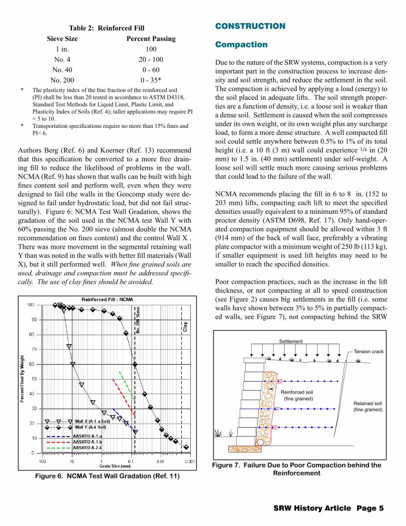
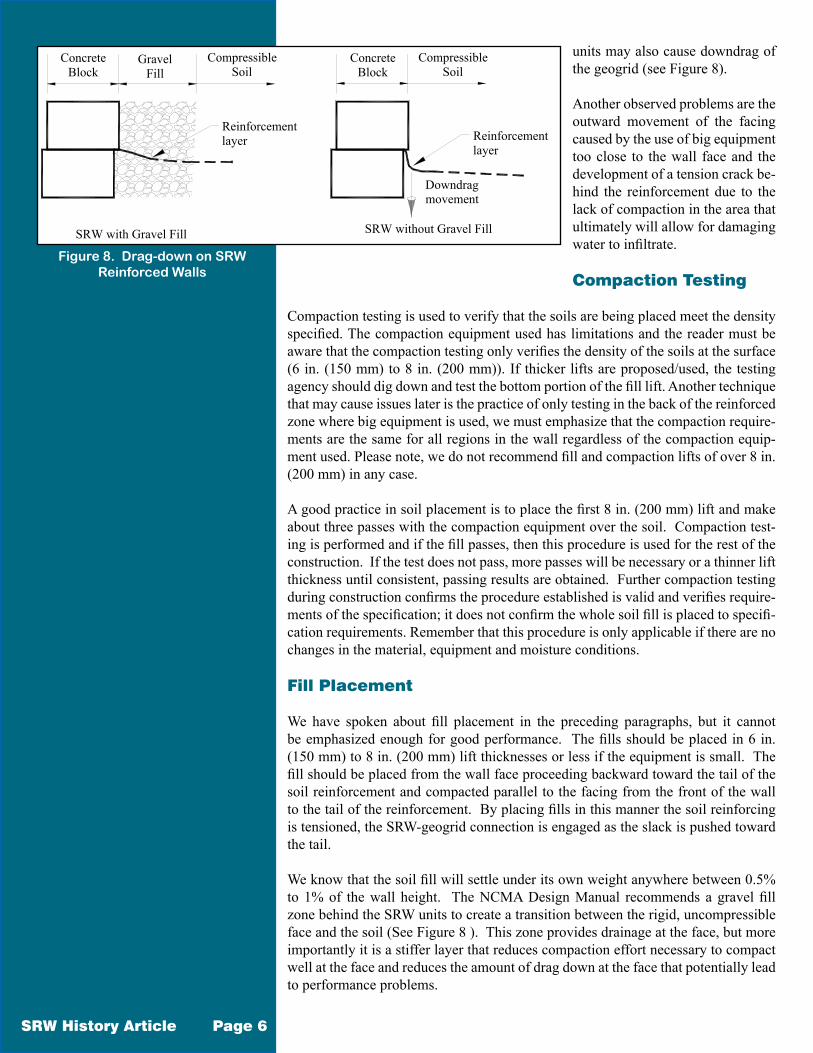
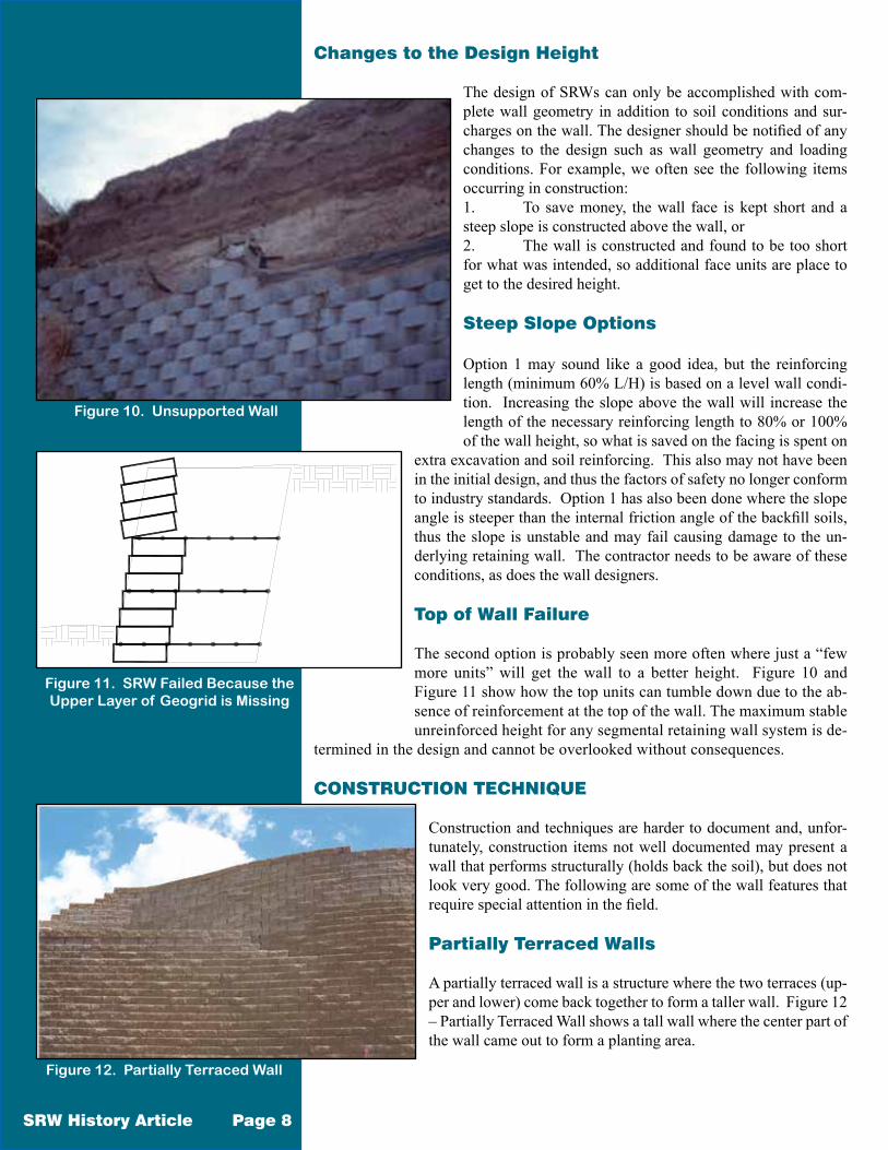
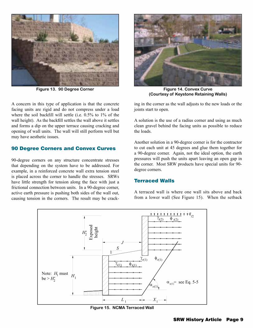
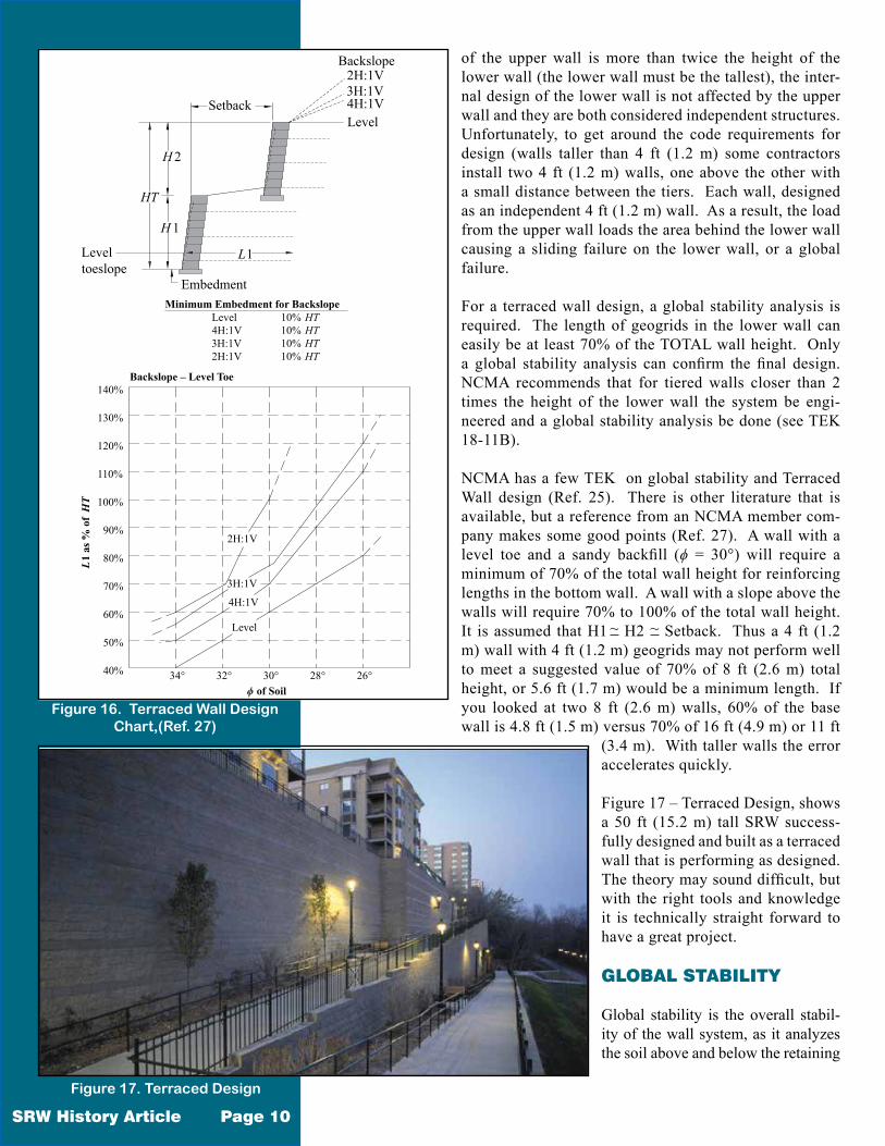
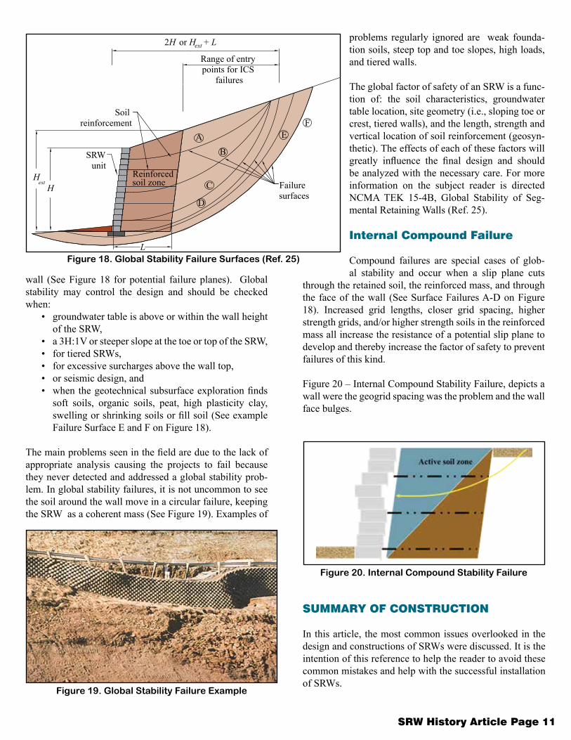
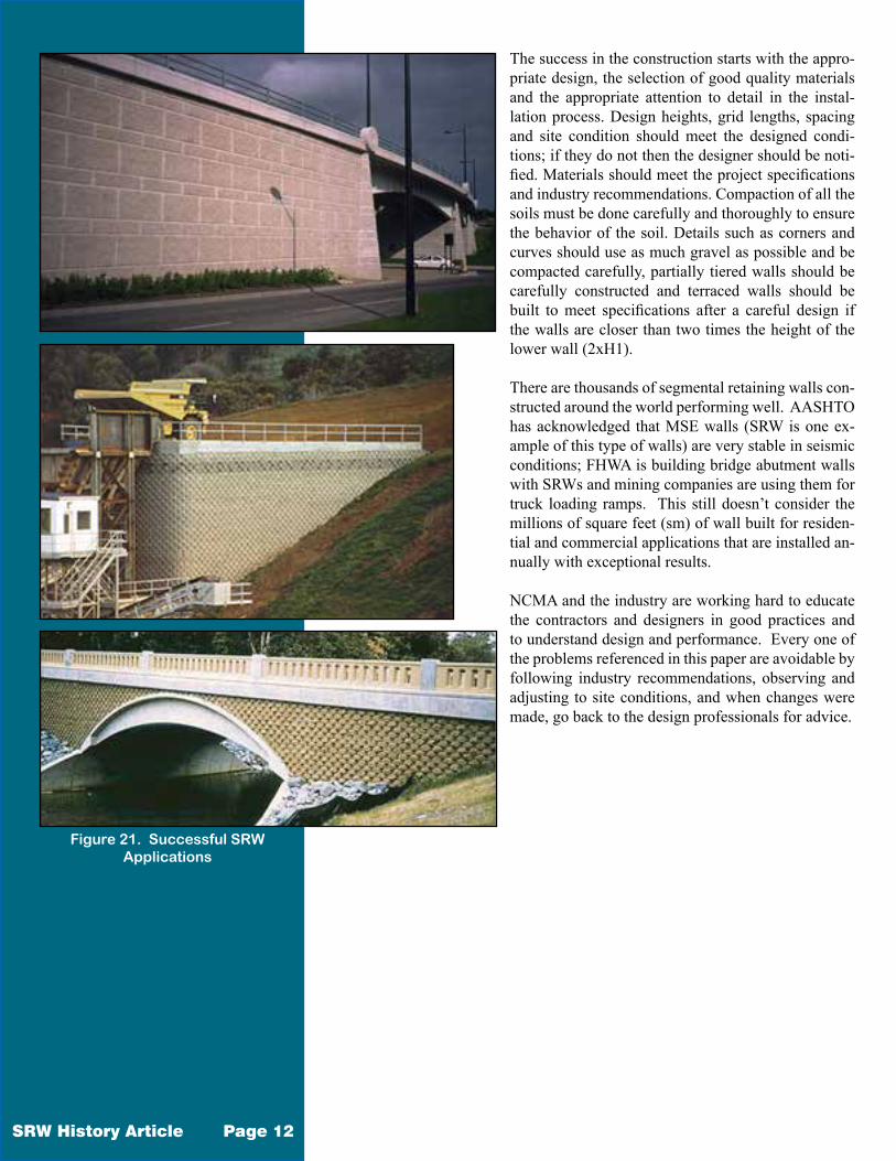