Embed Size (px)
Citation preview
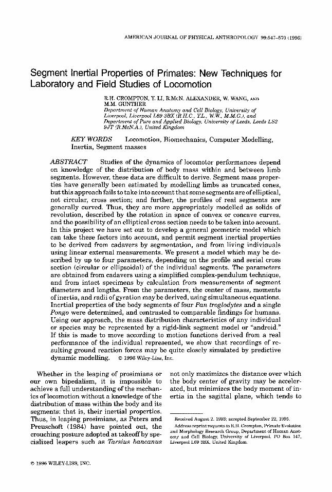
AMERICAN JOURNAL OF PHYSICAL ANTHROPOLOGY 99547-570 (1996)
Segment Inertial Properties of Primates: New Techniques for Laboratory and Field Studies of Locomotion
R.H. CROMFTON, Y. LI, R.McN. ALEXANDER, W. WANG, AND M.M. GUNTHER Department of Human Anatomy and Cell Biology, University of Liverpool, Liverpool L69 3BX (R.H.C., YL. , W.W., M.M.G.), and Department of Pure and Applied Biology, Uniuersity of Leeds, Leeds LS2 9JT (R.McN.A.), United Kingdom
KEY WORDS Inertia, Segment masses
Locomotion, Biomechanics, Computer Modelling,
ABSTRACT Studies of the dynamics of locomotor performances depend on knowledge of the distribution of body mass within and between limb segments. However, these data are difficult to derive. Segment mass proper- ties have generally been estimated by modelling limbs as truncated cones, but this approach fails to take into account that some segments are of elliptical, not circular, cross section; and further, the profiles of real segments are generally curved. Thus, they are more appropriately modelled as solids of revolution, described by the rotation in space of convex or concave curves, and the possibility of an elliptical cross section needs to be taken into account. In this project we have set out to develop a general geometric model which can take these factors into account, and permit segment inertial properties to be derived from cadavers by segmentation, and from living indiviauals using linear external measurements. We present a model which may be de- scribed by up to four parameters, depending on the profile and serial cross section (circular or ellipsoidal) of the individual segments. The parameters are obtained from cadavers using a simplified complex-pendulum technique, and from intact specimens by calculation from measurements of segment diameters and lengths. From the parameters, the center of mass, moments of inertia, and radii of gyration may be derived, using simultaneous equations. Inertial properties of the body segments of four Pan troglodytes and a single Pongo were determined, and contrasted to comparable findings for humans. Using our approach, the mass distribution characteristics of any individual o r species may be represented by a rigid-link segment model or “android.” If this is made to move according to motion functions derived from a real performance of the individual represented, we show that recordings of re- sulting ground reaction forces may be quite closely simulated by predictive dynamic modelling. o 1996 Wiley-Liss, Inc.
Whether in the leaping of prosimians or our own bipedalism, it is impossible to achieve a full understanding of the mechan- ics of locomotion without a knowledge of the distribution of mass within the body and its segments: that is, their inertial properties. Thus, in leaping prosimians, as Peters and Preuschoft (1984) have pointed out, the crouching posture adopted at takeoff by spe- cialized leapers such as Tarsius bancanus
not only maximizes the distance over which the body center of gravity may be acceler- ated, but minimizes the body moment of in- ertia in the sagittal plane, which tends to
Received August 2, 1993; accepted September 22, 1995. Address reprint requests to R.H. Crompton, Primate Evolution
and Morphology Research Group, Department of Human Anat- omy and Cell Biology, University of Liverpool, PO Box 147, Liverpool L69 3BX, United Kingdom.
0 1996 WILEY-LISS. INC
548 R.H. CROMPTON ET AL.
rotate the body towards the pull of gravity. On the other hand, as Crompton et al. (1993) have suggested, in the more generalized leapers such as mouse lemurs, long trunks and relatively low hindlimb masses may pro- duce moments of inertia too great to make ballistically optimal 45" takeoffs a mechani- cally efficient option. Inertial forces may also be useful, however: in the indriids, high fore- arm mass gives the forearms a moment of inertia that can be used to help rotate the body in flight (Demes and Gunther, 1989) so that long, powerful hindlimbs can be used to absorb the shock of landing.
Bipedal locomotion may be modelled as an inverted pendu1u.m (Cavagna et al., 1977; Mochon and McMahon, 1980; Hildebrand, 1985; Winter, 1990; Preuschoft and Witte, 1991). Such locomotion therefore follows the physical laws of pendular motion, which state that while the period of a pendulum is independent of the mass of the pendulum, it is not independent of its mass distribution (Hildebrand, 1985). Thus, the distribution of mass in the limb segments can be expected to affect stride parameters. Further, as Vi- lensky (1979) points out, the inertia of a seg- ment acts to resist changes in its angular motion, and is thus a determinant of its po- tential rapidity of oscillation. Several of the distinguishing features of the human trunk can be understood in terms of these princi- ples (Preuschoft and Witte, 1991). For exam- ple, the greater length of the human trunk increases its inertial resistance to sagittal oscillations induced by the pendular motion of the lower limbs; while the low shoulders and broad thorax of humans increase the inertial resistance of the trunk to oscillations in the position of the center of gravity about a vertical axis. But the research utility of segment inertial properties does not stop at qualitative comparisons: as Yamazaki et al. (1979) have shown, segment inertial data together with kinematic (motion) data can be used not only to calculate the forces actually occurring during a given recorded perfor- mance (which can more accurately be mea- sured using a forceplate), but also to predict the forces that would occur in given perfor- mances with different body proportions, so that we can actually experiment with the mechanical effects of evolutionary change.
Inertial properties are thus an essential aspect of studies of the dynamics of primate locomotion. Notwithstanding this, little ef- fort has been made by primatologists to mea- sure mass distribution. This neglect is cer- tainly in part a reflection of the difficulty of gathering such data, particularly on rare or endangered species. While the properties of mass, density, and volume can readily be measured by use of balances and simple water displacement methods, several im- portant parameters are difficult to obtain at sufficient levels of accuracy. These are the center of gravity (in essence, the mean when the distribution concerned is mass); the mo- ment of inertia (the characteristic distribu- tion of mass acting to resist a given angular acceleration); and the radius of gyration (es- sentially the standard deviation of mass dis- tribution about the mean).
While studies of mass distribution were carried out as long ago as 1860, by Harless, the most significant and painstaking work in this field is that of Dempster (1955), who derived weights, volumes, and joint centers of rotation, used balances to calculate cen- ters of gravity, and employed a complex-pen- dulum technique to calculate moments of in- ertia in 10 human cadavers. A variety of workers have attempted to refine these tech- niques and standardize method, but few have attempted to collect segment mass data from non-human primates. Grand (1977a) measured segment masses for a variety of primates and (1977b) examined segment masses in Macaca mulatta from a develop- mental perspective. However, he did not in- clude data on centers of gravity, moments of inertia, or radii of gyration. Zihlman (1984) and Morbeck and Zihlman (1988) likewise gave segment mass proportions, but no iner- tial data, for Pan paniscus, Pan troglodytes, and Pongo. Reynolds (1974), however, mea- sured masses, used the balance board tech- nique to measure centers of gravity, and used a simple-pendulum technique to measure principle moments of inertia in Papio cyno- cephalus. Vilensky (1979) used similar tech- niques to obtain masses, centers of gravity, and moments of inertia in Macaca mulatta, also giving regression equations for pre- dicting these parameters from body mass, and Wells and DeMenthon (1987) have de-
INERTIAL PROPERTIES OF PRIMATES 549
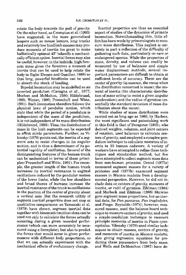
rived moments of inertia for Lemur fulvus using a rather different technique based on torsion in a bifilar (two-wire) pendulum ap- paratus. Their technique required two sepa- rate pieces of apparatus to measure the cen- ter of gravity (CG) and principal moments of inertia (PMI), and is not easily adopted for large primates. Sellers (1992) and Sellers and Crompton (1994) applied a geometric technique to estimation of the inertial prop- erties of small prosimians, which is appro- priate for rare museum specimens which can- not be segmented. None of these, however, have taken into account the elliptical (rather than cylindrical) nature of some segments, such as the trunk, hands, and feet, by distin- guishing the moments of inertia in the u and u axes (the long and short axes of a segment of elliptical cross section; see Fig. 1).
Tardieu (1991, 1992) and Tardieu et al. (1993) offered an alternative and rather un- orthodox approach to kiniesiological studies of chimpanzee and human bipedalism, which has revealed useful data about the methods used to achieve stable bipedal walk- ing by chimpanzees. Tardieu’s method used finite-element modelling to calculate the path of segment and body centers of gravity in living, moving subjects, while a t the same time producing data on the three-dimen- sional kinematics of the limbs. Subjects were enclosed in a close-fitting body suit divided up into squares, and four orthogonally ar- ranged motor-driven still cameras were used to record the motion and deformation of the volumes thus marked out. However, the ad- vantage gained from being able to record the deformation of body volumes during gait, even across joints, is somewhat negated by the consequent inability to perform free- body analysis of the dynamics of individual limb segments, an essential component of standard (e.g. Winter, 1990) dynamic analy- sis methods. Tardieu’s method also suffered from the rather large size of the cubic ele- ments employed, in relation to limb segment volume, and from poor temporal resolution (6 frames a second), although the higher res- olution of the 35 mm still camera format when compared to standard 16 mm cine or video to some extent offsets these disadvan- tages. The high level of subject training needed to permit use of body suits also lim-
‘ 1
Fig. 1. Geometric models of segments. Our geometric model of each body segment (A) is based on a column, with either an elliptical or circular cross section. In its most general form, the cross section is an ellipse, and circular cross sections are treated as a special case of elliptical sections. The base of the column lies in the u-u plane, the long axis of the ellipse being u and the short axis u. The segment may be thought of as a solid of revolution formed by rotation of the curve of its profile about its axis, z . It can be seen that the curve depends on the radii of the cross section u and u along its length. Four parameters, k, a, b, and c , and the density p are needed to describe the inertial properties of a solid of revolution with an elliptical axis. They can be estimated by measuring the long and short axes ofthe cross section at three distances along the long axis of the segment, zl, ul , 0 and zl, 0, ul, z2, u2, 0 and z2, 0, u2; and z3, u3, 0 and z3, 0, u3, using the method detailed in Appendix 1, for which the code is provided in Appendix 2. In a rod (B), the segment has a straight, not curved, outline, and parameter a has the value zero, and is not needed. If both a and b are zero, but c is non-zero, the model is a rod with a cross-sectional radius of 6.
ited detailed studies to a single, hand-reared subadult chimpanzee. Because of these limi- tations of Tardieu’s innovative technique, it is likely that most kiniesiological studies will continue to be based on rigid-link segment models (Bresler and Frankel, 1950) in which the inertial properties are given mathemati- cal, geometric, or physical representation. Geometric or mathematical modelling of in- ertial properties allows us to reduce the com- plexity of human and animal body shape, where multiple non-independent parame- ters-length, mass, center of mass, moments of inertia, and radii of gyration-must be simultaneously considered and compared.
550 R.H. CROMPTON ET AL.
B B 0
0 B U 0
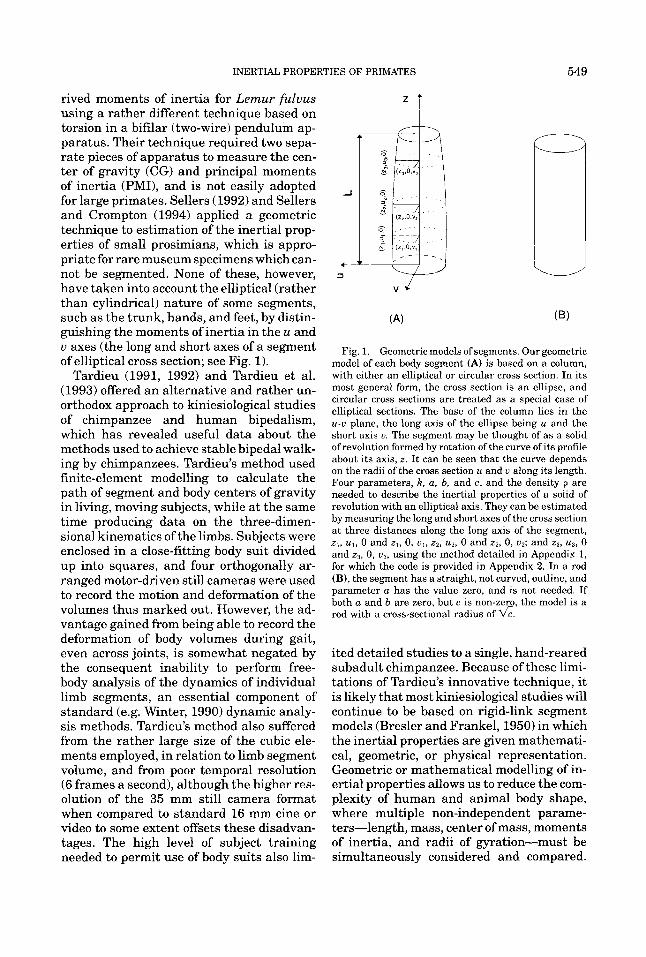
QQ Fig. 2. The geometric inertial model of Hanavan,
after Hanavan (1964). This model, based on truncated cones, does not take into account the convex or concave curvatures along the long axis of the segment.
Hanavan (19641, using conventional anthro- pometric data, constructed an inertial model on the basis of solid geometry (Fig. 2) where bars or truncated cones were used to repre- sent segment geometry. The changing shape of the segment cross section along the seg- ment (the x axis) was simply represented by circles of progressively diminishing radius. As Jensen (1978) remarked, such a model is clearly inaccurate, since segments such as the trunk, hands, and feet have an ellipsoi- dal, not circular, cross section, and in such a segment, we have seen that inertia will differ along the long (u) and short ( u ) axes of the ellipse. More recent models have not, to date, provided means of obtaining all three desired inertial parameters. That of
Clauser et al. (1969) considers mass and cen- ter of mass, but not moments of inertia. A model developed by one of us (Li, 1991) suc- ceeded in taking into consideration the cen- ter of gravity, the radius of gyration, and the convex or concave curvatures which may occur along the length of the segment (the z axis, see Fig. 1). However Li's (1991) model still failed to take into account ellipsoidal cross sections, and set segment lengths to unity.
In this paper, we have set out to develop methods which will permit segment inertial properties to be derived from cadavers by segmentation; and from living individuals using external measurements, based on a general geometric model which takes curva- tures and cross-sectional shape fully into consideration, and using techniques which follow the complex-pendulum approach of Dempster (1955) and Santschi et al. (1963). The mathematical procedures involved are given in Appendix A and FORTRAN-90 source code for the calculations in the method for intact specimens is given in Ap- pendix B.
For the first time, we report full inertial data for a sample of hominoids, and further illustrate the utility of our method by com- paring forceplate records of external reac- tion forces during bipedal gait of a human subject with forces calculated using pre- dictive dynamic modelling, in which motion (kinematics) derived from real performances are run through an inertial model of the subject.
METHODS Segment model
Our geometric model of each body segment (Fig. 1A) is based on a column with either an elliptical or circular cross section. In its most general form, the cross section is an ellipse, and circular cross sections are treated as a special case of elliptical sections. The base of the column lies in the plane u-u, the long axis of the ellipse being u and the short axis u. The segment may be thought of as a solid of revolution formed by rotation of the curve of its profile about its axis, z. It can be seen that the curve depends on the radii of the cross section u and u along
INERTIAL PROPERTIES OF PRIMATES 55 1
its length. Four parameters, k, a, b, and c, and the density p are needed to describe the inertial properties of a solid of revolution with an elliptical axis. They can be estimated by measuring the long and short axes of the cross section at three distances along the long axis of the segment, zb u b 0 and zb 0, ug zD uB 0 and 2% 0, u2; and z3, ug 0 and zg 0, ug using the method detailed in Appendix A, for which the code is provided in Appendix B. In a segment with a circular cross section, u = u, and since u is larger than u in the case of an elliptical cross section, the curve of the profile may also be termed u. The curve u may be described by u = q a z 2 + bz + c. There are four unknowns, k, a, b, and c, where 0 < k 5 1, and k is the ratio of the short axis of the ellipse, u over the long axis u. If the cross section is circular, then k = 1, and the three unknowns a, b, and c are the only parameters necessary to describe the shape of this segment. By changing these three parameters, the inertial properties of this segment can be satisfied. But, if the cross section is elliptical, four parameters, a, b, c, and k, are required. If a is greater than zero, the profile is a concave curve; if less than zero, convex (Fig. 1A). In a rod (Fig. lB), the segment has a straight, not curved outline, and parameter a has the value zero, and is not needed. If both a and b are zero, but c is non-zero, the model is a rod with a cross-sectional radius of 6.
Subjects Four common chimpanzees (Pan troglo-
dytes), two adult female, one adult male, and one juvenile male, and one juvenile orang- utan (Pongo pygmaeus) were used for this study. These specimens were captive-bred individuals, obtained after death from natu- ral causes a t the North of England Zoological Society’s Chester Zoo. The specimens had been kept on large, open islands with ample room and facilities for exercise. They did not exhibit any muscle wasting or other visible musculoskeletal abnormality. One Pan, Pan 2, was frozen shortly after death, and the other three specimens fixed in formol alcohol by perfusion and kept in tanks filled with methyl alcohol. The specimen of Pongo was perfused and then held frozen.
Segmentation For the purposes of this study, the body
was divided into the following segments: 1) head (with neck); 2) torso; 3) upper arm; 4) forearm; 5) hand; 6) thigh; 7) leg; 8) foot. These segments were chosen as those readily recognizable when analyzing film records, and form the links of our rigid-segment model. Segmentation may be done either fro- zen, by sawing, or unfrozen, by dissection. Dempster (1955) froze his specimens with the joints fixed at the angle midway through the range of motion of the joint concerned, and then sawed through the frozen limb at the approximate position of the center of ro- tation of the joint. His technique has the advantage that muscle is more readily as- signed to its biomechanically correct seg- ment. Segmentation by dissection of un- frozen cadavers suffers from the possibility of distortion of unfrozen muscle under grav- ity. However, primate cadavers are in our view too valuable to permit extensive saw- ing. Therefore, noting that there is no single ideal method of segmentation, we have adopted careful dissection of unfrozen speci- mens, cutting them so that muscle is divided between segments in a plane, sometimes curvilinear, passing through the estimated joint center. Whenever the fixation condi- tions permitted, the cut was made with a joint in the midposition of its approximate normal range of motion, for the plane of mo- tion in which the largest joint excursion oc- curs, as in Dempster (1955).
The segments were removed by careful dissection using a scalpel, a saw being used only to cut through vertebral bodies when the scalpel cut did not correspond to the posi- tion of the intervertebral disc. Great care was taken during dissection to prevent dis- tortion of the specimen under gravity, and the specimens were frozen, supported against gravity, immediately after separa- tion, to prevent later distortion.
Two Pan were segmented on both sides, so that techniques could be practised and verified before data were retained. The trial segmentations were recorded on videotape, so that subsequent segmentations could be made in as identical a manner as possible.
The divisions between segments were
552 R.H. CROMPTON ET AL.
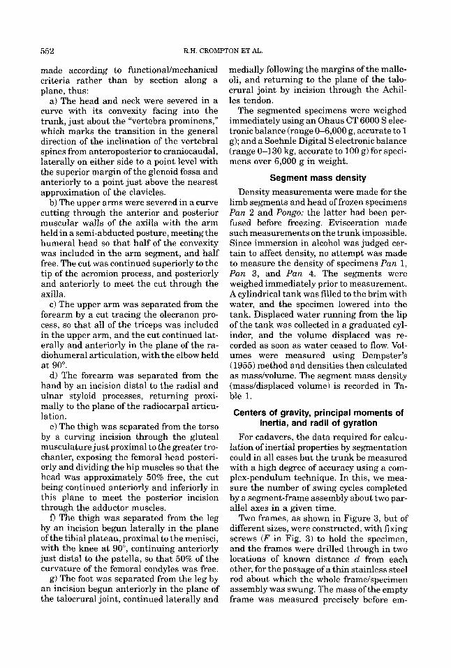
made according to functionaIJmechanica1 criteria rather than by section along a plane, thus:
a) The head and neck were severed in a curve with its convexity facing into the trunk, just about the “vertebra prominens,” which marks the transition in the general direction of the inclination of the vertebral spines from anteroposterior to craniocaudal, laterally on either side to a point level with the superior margin of the glenoid fossa and anteriorly to a point just above the nearest approximation of the clavicles.
b) The upper arms were severed in a curve cutting through the anterior and posterior muscular walls of the axilla with the arm held in a semi-abducted posture, meeting the humeral head so that half of the convexity was included in the arm segment, and half free. The cut was continued superiorly to the tip of the acromion process, and posteriorly and anteriorly to meet the cut through the axilla.
c) The upper arm was separated from the forearm by a cut tracing the olecranon pro- cess, so that all of the triceps was included in the upper arm, and the cut continued lat- erally and anteriorly in the plane of the ra- diohumeral articulation, with the elbow held at 90”.
d) The forearm was separated from the hand by an incision distal to the radial and ulnar styloid processes, returning proxi- mally to the plane of the radiocarpal articu- lation.
e) The thigh was separated from the torso by a curving incision through the gluteal musculature just proximal to the greater tro- chanter, exposing the femoral head posteri- orly and dividing the hip muscles so that the head was approximately 50% free, the cut being continued anteriorly and inferiorly in this plane to meet the posterior incision through the adductor muscles. fl The thigh was separated from the leg
by an incision begun laterally in the plane of the tibia1 plateau, proximal to the menisci, with the knee at go”, continuing anteriorly just distal to the patella, so that 50% of the curvature of the femoral condyles was free.
g) The foot was separated from the leg by an incision begun anteriorly in the plane of the talocrural joint, continued laterally and
medially following the margins of the malle- oli, and returning to the plane of the talo- crural joint by incision through the Achil- les tendon.
The segmented specimens were weighed immediately using an Ohaus CT 6000 S elec- tronic balance (range 0-6,000 g, accurate to 1 g); and a Soehnle Digital S electronic balance (range 0-130 kg, accurate to 100 g) for speci- mens over 6,000 g in weight.
Segment mass density Density measurements were made for the
limb segments and head of frozen specimens Pan 2 and Pongo: the latter had been per- fused before freezing. Evisceration made such measurements on the trunk impossible. Since immersion in alcohol was judged cer- tain to affect density, no attempt was made to measure the density of specimens Pan 1, Pan 3, and Pan 4. The segments were weighed immediately prior to measurement. A cylindrical tank was filled to the brim with water, and the specimen lowered into the tank. Displaced water running from the lip of the tank was collected in a graduated cyl- inder, and the volume displaced was re- corded as soon as water ceased to flow. Vol- umes were measured using Dempster’s (1955) method and densities then calculated as mass/volume. The segment mass density (mass/displaced volume) is recorded in Ta- ble 1.
Centers of gravity, principal moments of inertia, and radii of gyration
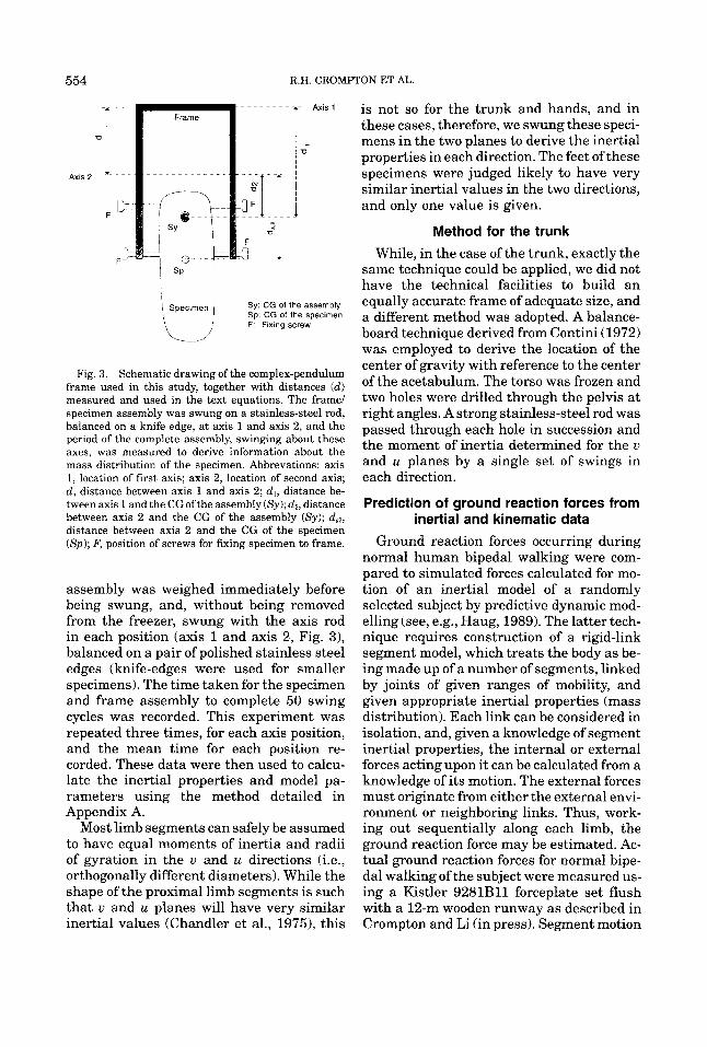
For cadavers, the data required for calcu- lation of inertial properties by segmentation could in all cases but the trunk be measured with a high degree of accuracy using a com- plex-pendulum technique. In this, we mea- sure the number of swing cycles completed by a segment-frame assembly about two par- allel axes in a given time.
Two frames, as shown in Figure 3, but of different sizes, were constructed, with fixing screws (F in Fig. 3) to hold the specimen, and the frames were drilled through in two locations of known distance d from each other, for the passage of a thin stainless steel rod about which the whole framehpecimen assembly was swung. The mass of the empty frame was measured precisely before em-
INERTIAL PROPERTIES OF PRIMATES 553
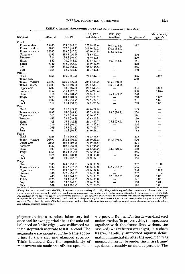
TABLE 1. Inertial characteristics of Pan and Pongo measured in this study
RG, (%P RGam (%Y Mass density Segment Mass (g) CG (%) (mediolateral) (sagittal) Length (mm) (g/cm3)
Pan 1 Trunk (entire) Trunk -abd. v. Trunk -viscera Upper arm Forearm Hand Thigh
Foot Pan 2
Head Trunk (est.) Trunk -viscera Trunk -s. sw. Upper arm Forearm Hand Thigh
Foot
Head Trunk -viscera Upper arm Forearm Hand Thigh
Foot Pan 4
Head Trunk -viscera Upper arm Forearm Hand Thigh
Foot Pongo
Head Trunk -viscera Upper arm Forearm Hand Thigh Leg Foot
Leg
Leg
Pan 3
Leg
Leg
18200 7200
12300 1281 935 332
2249 908 554
3054
18900 16000 2137 1642 616
3270 1382 712
787 1397 145 159 43
219 109 61
5025 26800 2564 2032
805 4351 2083 807
2938 5332 920 836 448
1070 686 528
-
219.0 (45.0) 237.0 (48.7) 229.0 (47.0) 113.9 (44.5) 136.3 (50.5) 70.0 (46.4)
108.0 (42.9) 133.2 (52.2) 63.2 (35.1)
106.0 (41.7)
215.6 (36.7) 274.3 (46.6) 130.0 (45.8) 144.4 (47.2) 98.7 (43.7)
113.7 (40.9) 153.7 (54.7) 71.4 (33.5)
61.7 (43.2) 125.6 (49.4) 55.7 (48.8) 58.9 (49.3) 35.9 (42.8) 45.6 (40.0) 58.9 (51.2) 44.7 (50.8)
97.1 (45.6) 253.4 (50.7) 118.8 (50.8) 110.1 (43.7) 67.8 (37.2)
114.4 (44.9) 113.0 (48.1) 69.2 (37.2)
124.0 (60.0) 195.5 (47.9) 109.5 (47.0) 142.2 (55.3) 73.2 (44.9) 79.1 (46.3) 93.8 (48.6) 69.7 (36.9)
-
155.8 (32.0) 166.0 (34.1) 167.9 (34.5) 78.6 (30.1) 75.0 (27.8) 47.8 (31.7) 84.0 (33.0) 65.8 (25.8) 46.1 (25.6)
70.3 (27.7)
223.2 (38.0) 189.0 (32.1) 86.7 (35.5) 80.4 (26.3) 61.9 (29.1) 82.7 (29.7) 77.7 (27.7) 54.3 (25.5)
42.6 (29.8) 82.7 (32.6) 35.0 (30.7) 32.6 (27.3) 24.1 (26.7) 35.1 (30.8) 30.7 (26.7) 23.0 (26.1)
76.2 (35.8) 131.0 (26.2) 74.0 (31.6) 70.6 (28.0) 52.6 (28.9) 79.8 (31.3) 66.6 (28.3) 50.9 (27.4)
64.0 (30.9) 142.3 (34.9) 80.5 (34.5) 72.0 (28.0) 54.9 (33.7) 59.9 (35.0) 57.6 (29.8) 54.2 (28.7)
-
160.4 (32.9) 170.4 (35.0) 173.2 (35.6)
- -
50.0 (33.1) - - -
- -
234.5 (39.9) 196.0 (33.3)
- -
25.1 (29.9) - - -
- 89.6 (35.3) - -
25.1 (29.9) - - -
-
151.5 (30.3) - -
53.3 (29.3) - - -
-
146.7 (36.0) - -
52.9 (32.5) - - -
487 - -
256 270 151 252 255 180
245 588 - -
284 306 226 278 28 1 213
143 254 114 120 84
114 115 88
213 500 234 252 182 255 235 186
207 515 233 257 163 171 193 189
- - - - - - - - -
1.067 - - -
1.069 1.074 1.11 1.037 1.08 1.09
- - - - - - - -
- - - - - - - -
1.116
1.062 1.105 1.05 1.05 1.04 1.03
-
=Except for the hand and trunk, the RG, of segments are assumed equal to RG,. They axis is sagittal, the x axis coronal. ' h n k -viscera = trunk minus all viscera; trunk -abd. v. = trunk minus abdominal viscera, etc. (est.) = intact mass, estimated by technique given in the text. The positions of the center of gravity are normally distances of the center of gravity from the proximal joint center, expressed a s percentages of segment length. In the case of the feet, trunk, and head, the proximal joint center does not, of course, correspond to the proximal end of the segment. The centers of gravity of the foot, trunk, and head are thus defined with reference to the calcaneal tuberosity, center of the acetabulum, and external occipital protuberance.
ployment using a standard laboratory bal- ance and its swing period about the axis rod, balanced on knife-edges, was calibrated us- ing a stopwatch accurate to 0.01 second. The segments were mounted in the frame appro- priate to their size and clamped securely. Trials indicated that the repeatability of measurements made on unfrozen specimens
was poor, as fluid andor tissue was displaced under gravity. To prevent this, the specimen together with the frame (but without the axis rod) was refrozen overnight, in a chest freezer, carefully supported against defor- mation, immediately after the specimen was mounted, in order to render the entire frame/ specimen assembly as rigid as possible. The
554 R.H. CROMPTON ET AL
AXlS
Sy: CG of the assembly Sp: CG of the specimen F: Fixing screw
Fig. 3. Schematic drawing of the complex-pendulum frame used in this study, together with distances (d) measured and used in the text equations. The frame/ specimen assembly was swung on a stainless-steel rod, balanced on a knife edge, at axis 1 and axis 2, and the period of the complete assembly, swinging about these axes, was measured to derive information about the mass distribution of the specimen. Abbrevations: axis 1, location of first axis; axis 2, location of second axis; d , distance between axis 1 and axis 2; d,, distance be- tween axis 1 and the CGofthe assembly ( S y ) ; dz, distance between axis 2 and the CG of the assembly (Sy) ; d,,, distance between axis 2 and the CG of the specimen (Sp); F, position of screws for fixing specimen to frame.
assembly was weighed immediately before being swung, and, without being removed from the freezer, swung with the axis rod in each position (axis 1 and axis 2, Fig. 3), balanced on a pair of polished stainless steel edges (knife-edges were used for smaller specimens). The time taken for the specimen and frame assembly to complete 50 swing cycles was recorded. This experiment was repeated three times, for each axis position, and the mean time for each position re- corded. These data were then used to calcu- late the inertial properties and model pa- rameters using the method detailed in Appendix A.
Most limb segments can safely be assumed to have equal moments of inertia and radii of gyration in the u and u directions (i.e., orthogonally different diameters). While the shape of the proximal limb segments is such that u and u planes will have very similar inertial values (Chandler et al., 1975), this
is not so for the trunk and hands, and in these cases, therefore, we swung these speci- mens in the two planes to derive the inertial properties in each direction. The feet of these specimens were judged likely to have very similar inertial values in the two directions, and only one value is given.
Method for the trunk While, in the case of the trunk, exactly the
same technique could be applied, we did not have the technical facilities to build an equally accurate frame of adequate size, and a different method was adopted. A balance- board technique derived from Contini (1972) was employed to derive the location of the center of gravity with reference to the center of the acetabulum. The torso was frozen and two holes were drilled through the pelvis a t right angles. A strong stainless-steel rod was passed through each hole in succession and the moment of inertia determined for the u and u planes by a single set of swings in each direction.
Prediction of ground reaction forces from inertial and kinematic data
Ground reaction forces occurring during normal human bipedal walking were com- pared to simulated forces calculated for mo- tion of an inertial model of a randomly selected subject by predictive dynamic mod- elling (see, e.g., Haug, 1989). The latter tech- nique requires construction of a rigid-link segment model, which treats the body as be- ing made up of a number of segments, linked by joints of given ranges of mobility, and given appropriate inertial properties (mass distribution). Each link can be considered in isolation, and, given a knowledge of segment inertial properties, the internal or external forces acting upon it can be calculated from a knowledge of its motion. The external forces must originate from either the external envi- ronment or neighboring links. Thus, work- ing out sequentially along each limb, the ground reaction force may be estimated. Ac- tual ground reaction forces for normal bipe- dal walking of the subject were measured us- ing a Kistler 9281B11 forceplate set flush with a 12-m wooden runway as described in Crompton and Li (in press). Segment motion
INERTIAL PROPERTIES OF PRIMATES 555
(angular and linear accelerations and veloci- ties [i.e. kinematics]) was recorded synchro- nously using two orthogonal genlocked CCD video cameras, and reconstructed in 3-D us- ing our own software, GAP (Sellers and Crompton, 1994). Then, a rigid-link com- puter model (android) of the subjects’ dimen- sions and inertial properties of the subject was constructed using the preprocessor of a standard commercial dynamic modeller, ADAMS/Android (MDI Inc., 1992) on the ba- sis of anthropometric measurements and the Chandler et al. (1975) database. Standard ranges of joint mobility, and appropriate lev- els of compliance and damping at joints, were utilized. Motion curves describing the linear and angular accelerations and velocities of the subject’s segments (derived from the ki- nematic recordings) were then used to drive the computer representation of the subject using ADAMS/Solver (MDI Inc., 19921, and the forces necessary at each joint to bring about these kinematics, given the inertial properties of the model, were then calculated. Working out from the body center ofgravity to the sequential ground-subject contact points the resulting ground reaction forces could then be calculated by the methods detailed in Haug (1989) and Winter (1990).
RESULTS Five trials of the complex-pendulum tech-
nique were made using an artificial limb seg- ment (part of a shop display dummy) of mass 845 g in a frame of mass 145 g. These pro- duced principal moments of inertia (PMIs) with a coefficient of variation of 0.46%. The radii of gyration had a coefficient of variation of 0.23%. The mass, mass densities, centers of gravity, and radii of gyration of the seg- ments of each specimen studied in this proj- ect are given in Table 1. The principal mo- ment of inertia (PMI) is simply the product of the mass and the square of the radius of gyration, which are reported here as inde- pendent parameters. The PMI is therefore not listed.
Density measurements of Pan 2 produced the result predicted by Dempster (1955): the more distal segments have progressively higher density. However, the Pongo results
are less satisfactory in the latter respect, suggesting that any perfusion previous to freezing may change the density properties of limb segments.
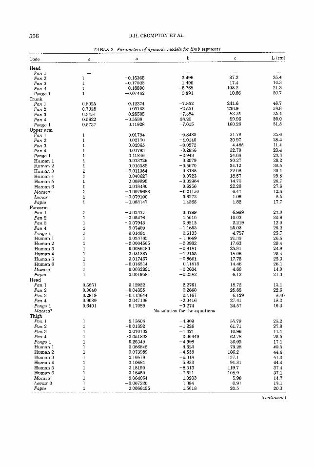
Our own sample size is necessarily small, as our material is, of course, limited to that provided by natural deaths of captive ani- mals. However, we present the parameters of the inertial models created in this study in Table 2, together with values for six adult male human cadavers calculated from Chan- dler et al. (19751, which is the study most directly comparable with our own. Where the data were sufficient, and the results thought reasonable reliable, we also present parameters calculated from Reynolds’ (1974) study of four female Papio, Vilensky’s (1979) male and female means for Macaca mulatta, and Wells’ and De Menthon’s (1987) study of a single Lemur fuluus. Figure 4 gives a graphic representation of the inertial models of Pan 1, Pan 2, Pan 4, and Pongo 1. In Table 3, mass proportion data are presented together with data on three children from Jensen (19871, Zihlman (1984) on Panpanis- cus, and Morbeck and Zihlman (1988) on two Pongo (Pongo 2 and Pongo 3).
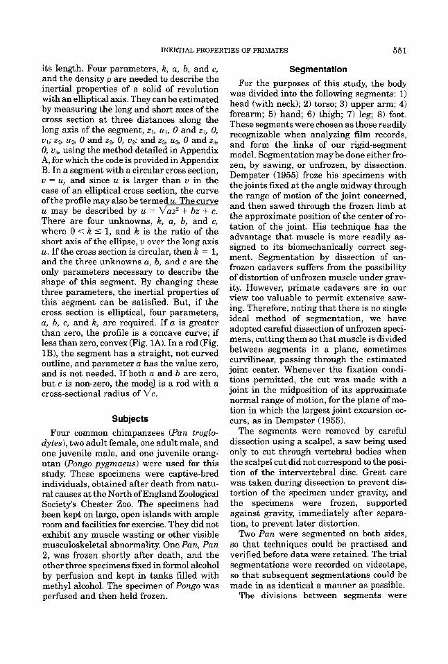
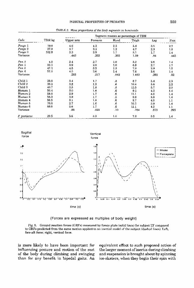
Figure 5 shows simulated vertical and sa- gittal (or fore-aft) reaction forces between the foot and ground during the stance phase in comparison to those actually recorded by the Kistler forceplate during the same phase in the real performance. It can be seen that the real forces are well predicted, but the magnitude and sharpness of the peaks and troughs of the curves are sometimes differ- ent in the two sets of curves.
DISCUSSION The inertial characteristics (Table 1) of
hominoids measured in this study bear clos- est comparison with the work of Chandler et al. (1975) on human cadavers. The mean position of the center of gravity (CG) of the upper arm is more proximal in Pan (44.5% and 46.6% for the two females, and 47% for the infant Pongo, but 50.8% for the adult male Pan) than it is in humans, where Li and Dangerfield (1993) found that the CG becomes progressively more proximal in children of increasing age. The forearm, on
Code
Head Pan 1 Pan 2 Pan 3 Pan 4 Pongo 1
Pan 1 Pan 2 Pan 3 Pan 4 Pongo 1
Upper arm Pan 1 Pan 2 Pan 3 Pan 4 Pongo 1 Human 1 Human 2 Human 3 Human 4 Human 5 Human 6 Macaca' Lemur Papio
Forearm Pan 1 Pan 2 Pan 3 Pan 4 Pongo 1 Human 1 Human 2 Human 3 Human 4 Human 5 Human 6 Macaca' Papio
Pan 1 Pan 2 Pan 3 Pan 4 Pongo 1 Macaca'
Pan 1 Pan 2 Pan 3 Pan 4 Pongo 1 Human 1 Human 2 Human 3 Human 4 Human 5 Human 6 Macaca' Lemur 3 Papio
Trunk
Head
Thigh
556 R.H. CROMPTON ET AL.
TABLE 2. Parameters of dynamic models for limb segments
k a b C L (cm)
-
1 1 1 1
0.8025 0.7325 0.3451 0.5622 0.5737
1 1 1 1 1 1 1 1 1 1 1 1 1 1
1 1 1 1 1 1 1 1 1 1 1 1 1
0.5551 0.3640 0.2819 0.9039 0.6401
1 1 1 1 1 1 1 1 1 1 1 1 1 1
-
-0.15365 -0.17023
-0.07462 0.18890
0.12374 0.01133 0.28505
0.11928
0.01794 0.02170 0.01965 0.01793 0.11846 0.013726 0.015585
-0.011354 0.040627 0.008895 0.018480
-0.5538
-0.0079683 -0.079100 -0.083147
-0.02437 -0.05476 -0.07943
-0.01484
-0.0004565
0.07469
0.033783
0.0086180 0.031387 0.017467
0.0032891 0.0019581
0.12922
-0.016514
-0.04355 -0.113644
0.047106 0.17089
0.15806
0.070132
0.26349 0.066845 0.073989 0.10878 0.10681 0.18190 0.16450
-0.064064 -0.067226 -0.0086155
-0.01392
-0.051823
-
2.496 1.490
3.891 -5.768
-7.852 -2.551 -7.384
-7.015
-0.8433 -1.0140 -0.0272 -0.2856 -2.943 -0.2979 -0.5670
0.3138 -0.0723 -0.02964 -0.6256 -0.01150
28.20
0.6272 1.4368
0.6799 1.5010 0.9215
0.6133 - 1.1653
- 1.3689 -0.3932 -0.9181 -1.2155 -0.8661
-0.2634 -0.2382
-2.2761
0.11813
0.2660 0.4167
-2.0416 -3.274
No solution for the equations
-4.909 -1.226 -1.421
-4.998 -3.623 -4.558 -6.318 -5.833 -8.513 -7.621
0.06449
1.0203 1.084
-1.5018
- 37.2 17.4
103.2 10.86
241.6 236.9
83.21 59.96
160.26
21.78 30.97
32.70 24.68 20.27 24.12 22.08 18.57 14.75 22.28 6.47 1.06 1.82
6.999
2.219
4.757
4.485
10.03
25.03
21.33 17.63 25.81 18.06 17.75 14.46 4.88 6.12
18.72 25.88
27.41 24.57
6.129
55.79 61.71 10.96 62.78 36.02 79.28
106.2 137.1
119.7 108.9
91.31
5.90 0.91
20.5
- 25.4 14.3 21.3 20.7
48.7 58.8 25.4 50.0 51.5
25.6 28.4 11.4 23.4 23.3 28.2 30.5 29.1 29.8 26.7 27.6 12.6 8.5
17.7
27.0 30.6 12.0 25.2 25.7 26.6 29.4 24.9 25.4 25.3 26.1 14.0 21.3
15.1 22.6
18.2 16.3
8.40
25.2 27.8 11.4 25.5 17.1 40.5 44.4 41.0 44.4 37.4 37.1 14.7 13.1 20.3
(continued)
INERTIAL PROPERTIES OF PRIMATES 557
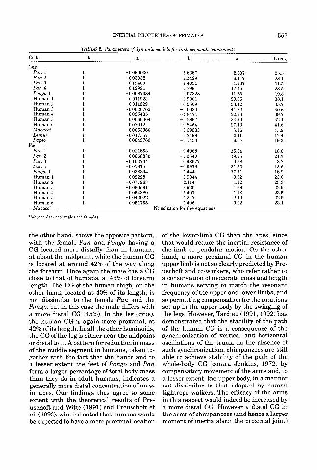
TABLE 2. Parameters of dynamic models for limb segments (continued)
Code k a b C L (cm)
Pan 1 1 -0.060000 1.6387 2.607 25.5
Pan 3 1 -0.12459 1.4891 1.287 11.5 Pan 4 1 0.12991 2.799 17.15 23.5 Pongo 1 1 -0.0087034 0.07328 11.25 19.3 Human 1 1 0.011923 -0.9001 29.06 38.1 Human 2 1 0.011329 -0.9509 33.42 45.7 Human 3 1 -0.0020762 -0.6684 41.22 40.6 Human 4 1 0.035405 -1.8474 32.76 39.7 Human 5 1 0.0066464 -0.5897 24.99 42.4 Human 6 1 0.01012 -0.8454 27.43 41.6 Macaca' 1 -0.0063360 -0.09333 5.16 15.9 Lemur 1 -0.017557 0.3498 0.11 12.4 Papio 1 -0.0043769 -0.1453 6.64 19.3
Pan 1 1 -0.021853 -0.4988 15.84 18.0 Pan 2 1 0.0068830 -1.0540 19.95 21.3 Pan 3 1 -0.103734 0.93577 0.58 8.8 Pan 4 1 -0.01874 -0.6978 21.32 18.6 Pongo 1 1 0.038394 -1.444 17.71 18.9 Human 1 1 -0.02228 0.9344 3.52 23.0 Human 2 1 -0.071963 2.114 1.12 25.3 Human 3 1 -0.066561 1.925 1.66 22.9 Human 4 1 -0.054389 1.497 1.18 23.5 Human 5 1 -0.042022 1.247 2.49 22.5 Human 6 1 -0.051755 1.495 0.02 23.1 Macaca'
Leg
Pan 2 1 -0.03032 1.1429 6.417 28.1
Foot
No solution for the eauations
'Macaca data pool males and females
the other hand, shows the opposite pattern, with the female Pan and Pongo having a CG located more distally than in humans, a t about the midpoint, while the human CG is located at around 42% of the way along the forearm. Once again the male has a CG close to that of humans, at 43% of forearm length. The CG of the human thigh, on the other hand, located at 40% of its length, is not dissimilar to the female Pan and the Pongo, but in this case the male differs with a more distal CG (45%). In the leg (crus), the human CG is again more proximal, a t 42% of its length. In all the other hominoids, the CG of the leg is either near the midpoint or distal to it. A pattern for reduction in mass of the middle segment in humans, taken to- gether with the fact that the hands and to a lesser extent the feet of Pongo and Pan form a larger percentage of total body mass than they do in adult humans, indicates a generally more distal concentration of mass in apes. Our findings thus agree to some extent with the theoretical results of Pre- uschoft and Witte (1991) and Preuschoft et al. (1992)) who indicated that humans would be expected to have a more proximal location
of the lower-limb CG than the apes, since that would reduce the inertial resistance of the limb to pendular motion. On the other hand, a more proximal CG in the human upper limb is not so clearly predicted by Pre- uschoft and co-workers, who refer rather to a conservation of moderate mass and length in humans serving to match the resonant frequency of the upper and lower limbs, and so permitting compensation for the rotations set up in the upper body by the swinging of the legs. However, Tardieu (1991,1992) has demonstrated that the stability of the path of the human CG is a consequence of the synchronization of vertical and horizontal oscillations of the trunk. In the absence of such synchronization, chimpanzees are still able to achieve stability of the path of the whole-body CG (contra Jenkins, 1972) by compensatory movement of the arms and, to a lesser extent, the upper body, in a manner not dissimilar to that adopted by human tightrope walkers. The efficacy of the arms in this respect would indeed be increased by a more distal CG. However a distal CG in the arms of chimpanzees (and hence a larger moment of inertia about the proximal joint)
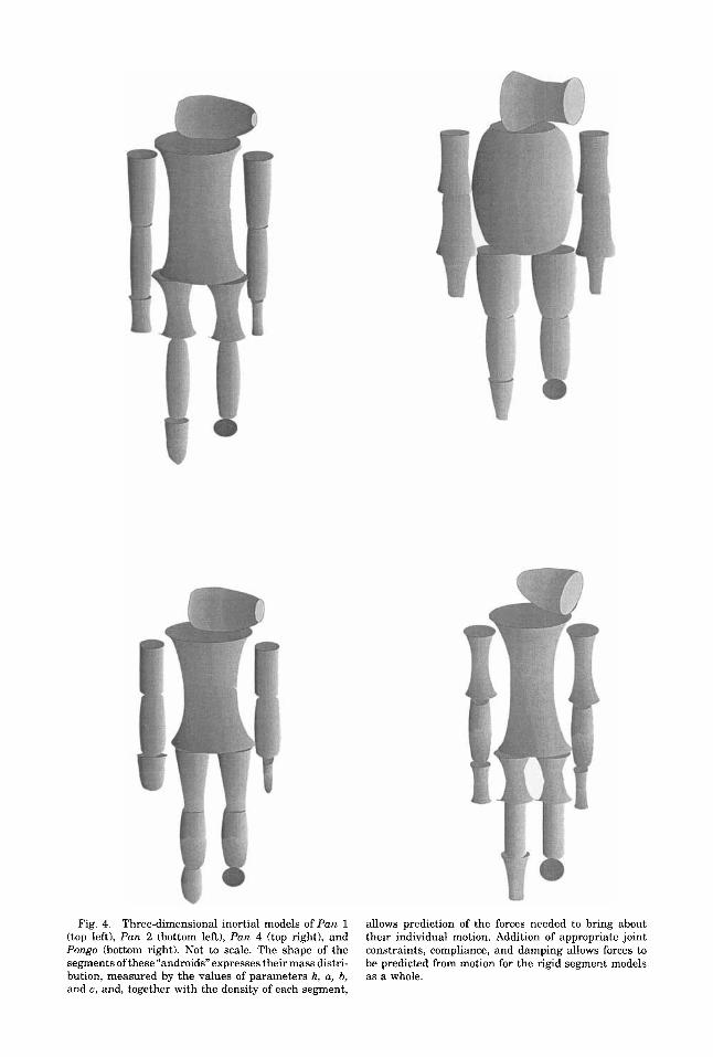
Fig. 4. Three-dimensional inertial models of Pan 1 (top left), Pan 2 (bottom left), Pan 4 (top right), and Pongo (bottom right). Not to scale. The shape of the segments ofthese “androids” expresses their mass distri- bution, measured by the values of parameters k, a, b, and c, and, together with the density of each segment,
allows prediction of the forces needed to bring about their individual motion. Addition of appropriate joint constraints, compliance, and damping allows forces to be predicted from motion for the rigid segment models as a whole.
INERTIAL PROPERTIES OF PRIMATES 559
TABLE 3. Mass proportions of the limb segments in hominoids
Segment masses as percentage of TBM Code TBM kg Upper arm Forearm Hand Thigh Leg Foot
Pongo 1 19.8 4.6 4.2 2.3 5.4 3.5 2.7 Pongo 2 27.8 3.7 3.2 1.2 4.7 2.3 1.8 Pongo 3 102.8 3.3 3.9 1.7 3.1 1.7 1.4 Variance ,443 ,263 ,303 1.39 .84 .443
Pan 3 4.0 3.4 2.7 1.0 5.2 2.6 1.4 Pan 1 33.1 3.9 2.8 1.0 6.8 2.7 1.7 Pan 2 47.1 4.5 3.5 1.3 7.9 2.9 1.5 Pan 4 57.1 4.5 3.6 1.4 7.6 3.6 1.4 Variance ,283 .217 ,042 1.462 ,203 .02
Child 1 Child 2 Child 3 Human 1 Human 2 Human 3 Human 4 Human 5 Human 6 Variance
28.8 39.3 40.7 50.4 58.0 58.3 58.5 76.0 89.0
3.4 3.2 3.5 3.0 2.9 3.0 3.1 2.7 2.6
.88
1.7 1.3 1.8 1.6 1.7 1.7 1.8 1.6 1.7 ,023
.8
.6
.8
.6
.6
.5
.6
.6
.6
.10
8.7 10.4 11.0 9.1
11.1 9.8 9.7
10.1 11.1
.764
5.4 5.6 5.7 4.3 4.5 3.8 4.0 3.9 4.2
,575
2.3 2.3 2.3 1.4 1.4 1.4 1.1 1.4 1.1 .265
Z? paniscus 29.5 3.6 3.3 1.0 7.2 3.5 1.4
Sagittal force
0 0 0 5 0 1 015 02 0 2 5 0.3 035 0 4 0 4 5 0 5 055’ .O.d
Vertical force
time (s) time (s)
(Forces are expressed as multiples of body weight)
Fig. 5. Ground reaction forces (GRFs) measured by forece plate (solid lines) for subject LY compared to GRFs predicted from the same motion applied to an inertial model of the subject (dashed lines). Left, fore-aft force; right, vertical force.
is more likely to have been important for influencing posture and motion of the rest of the body during climbing and swinging than for any benefit in bipedal gaits. An
equivalent effect to such proposed action of the larger moment of inertia during climbing and suspension is brought about by spinning ice-skaters, when they begin their spin with
560 R.H. CROMPTON ET AL.
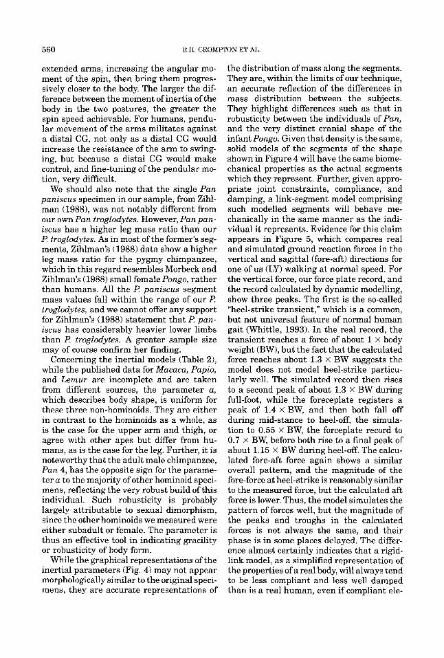
extended arms, increasing the angular mo- ment of the spin, then bring them progres- sively closer to the body. The larger the dif- ference between the moment of inertia of the body in the two postures, the greater the spin speed achievable. For humans, pendu- lar movement of the arms militates against a distal CG, not only as a distal CG would increase the resistance of the arm to swing- ing, but because a distal CG would make control, and fine-tuning of the pendular mo- tion, very difficult.
We should also note that the single Pan paniscus specimen in our sample, from Zihl- man (19881, was not notably different from our own Pan troglodytes. However, Pan pan- iscus has a higher leg mass ratio than our I! troglodytes. As in most of the former’s seg- ments, Zihlman’s (1988) data show a higher leg mass ratio for the pygmy chimpanzee, which in this regard resembles Morbeck and Zihlman’s (1988) small female Pongo, rather than humans. All the I! paniscus segment mass values fall within the range of our Z? troglodytes, and we cannot offer any support for Zihlman’s (1988) statement that I! pan- iscus has considerably heavier lower limbs than I? troglodytes. A greater sample size may of course confirm her finding.
Concerning the inertial models (Table 21, while the published data for Macaca, Papio, and Lemur are incomplete and are taken from different sources, the parameter a, which describes body shape, is uniform for these three non-hominoids. They are either in contrast to the hominoids as a whole, as is the case for the upper arm and thigh, or agree with other apes but differ from hu- mans, as is the case for the leg. Further, it is noteworthy that the adult male chimpanzee, Pan 4, has the opposite sign for the parame- ter a to the majority of other hominoid speci- mens, reflecting the very robust build of this individual. Such robusticity is probably largely attributable to sexual dimorphism, since the other hominoids we measured were either subadult or female. The parameter is thus an effective tool in indicating gracility or robusticity of body form.
While the graphical representations of the inertial parameters (Fig. 4) may not appear morphologically similar to the original speci- mens, they are accurate representations of
the distribution of mass along the segments. They are, within the limits of our technique, an accurate reflection of the differences in mass distribution between the subjects. They highlight differences such as that in robusticity between the individuals of Pan, and the very distinct cranial shape of the infant Pongo. Given that density is the same, solid models of the segments of the shape shown in Figure 4 will have the same biome- chanical properties as the actual segments which they represent. Further, given appro- priate joint constraints, compliance, and damping, a link-segment model comprising such modelled segments will behave me- chanically in the same manner as the indi- vidual it represents. Evidence for this claim appears in Figure 5, which compares real and simulated ground reaction forces in the vertical and sagittal (fore-aft) directions for one of us (LY) walking at normal speed. For the vertical force, our force plate record, and the record calculated by dynamic modelling, show three peaks. The first is the so-called “heel-strike transient,” which is a common, but not universal feature of normal human gait (Whittle, 1993). In the real record, the transient reaches a force of about 1 x body weight (BW), but the fact that the calculated force reaches about 1.3 X BW suggests the model does not model heel-strike particu- larly well. The simulated record then rises to a second peak of about 1.3 x BW during full-foot, while the foreceplate registers a peak of 1.4 X BW, and then both fall off during mid-stance to heel-off, the simula- tion to 0.55 X BW, the forceplate record to 0.7 X BW, before both rise to a final peak of about 1.15 X BW during heel-off. The calcu- lated fore-aft force again shows a similar overall pattern, and the magnitude of the fore-force at heel-strike is reasonably similar to the measured force, but the calculated aft force is lower. Thus, the model simulates the pattern of forces well, but the magnitude of the peaks and troughs in the calculated forces is not always the same, and their phase is in some places delayed. The differ- ence almost certainly indicates that a rigid- link model, as a simplified representation of the properties of a real body, will always tend to be less compliant and less well damped than is a real human, even if compliant ele-
INERTIAL PROPERTIES OF PRIMATES 56 1
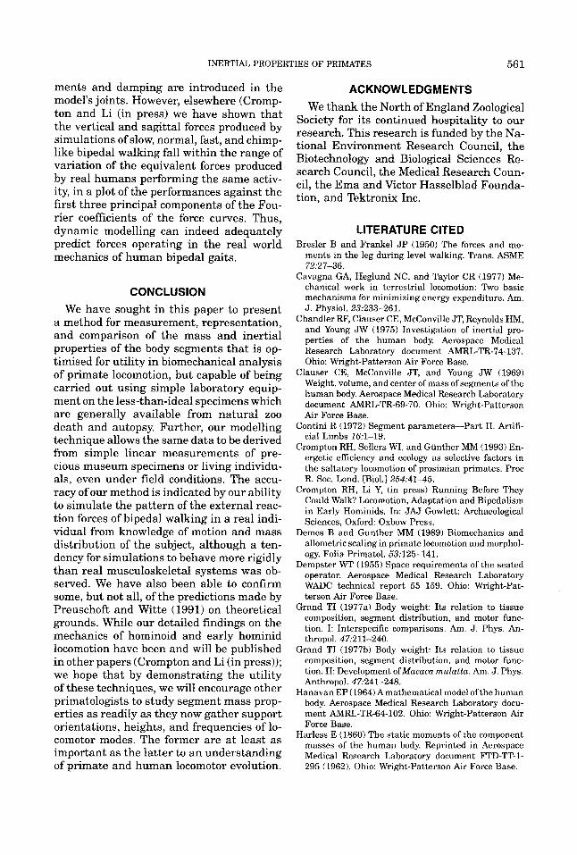
ments and damping are introduced in the model's joints. However, elsewhere (Cromp- ton and Li (in press) we have shown that the vertical and sagittal forces produced by simulations of slow, normal, fast, and chimp- like bipedal walking fall within the range of variation of the equivalent forces produced by real humans performing the same activ- ity, in a plot of the performances against the first three principal components of the Fou- rier coefficients of the force curves. Thus, dynamic modelling can indeed adequately predict forces operating in the real world mechanics of human bipedal gaits.
CONCLUSION We have sought in this paper to present
a method for measurement, representation, and comparison of the mass and inertial properties of the body segments that is op- timised for utility in biomechanical analysis of primate locomotion, but capable of being carried out using simple laboratory equip- ment on the less-than-ideal specimens which are generally available from natural zoo death and autopsy. Further, our modelling technique allows the same data to be derived from simple linear measurements of pre- cious museum specimens or living individu- als, even under field conditions. The accu- racy of our method is indicated by our ability to simulate the pattern of the external reac- tion forces of bipedal walking in a real indi- vidual from knowledge of motion and mass distribution of the subject, although a ten- dency for simulations to behave more rigidly than real musculoskeletal systems was ob- served. We have also been able to confirm some, but not all, of the predictions made by Preuschoft and Witte (1991) on theoretical grounds. While our detailed findings on the mechanics of hominoid and early hominid locomotion have been and will be published in other papers (Crompton and Li (in press)); we hope that by demonstrating the utility of these techniques, we will encourage other primatologists to study segment mass prop- erties as readily as they now gather support orientations, heights, and frequencies of lo- comotor modes. The former are a t least as important as the latter to an understanding of primate and human locomotor evolution.
ACKNOWLEDGMENTS We thank the North of England Zoological
Society for its continued hospitality to our research. This research is funded by the Na- tional Environment Research Council, the Biotechnology and Biological Sciences Re- search Council, the Medical Research Coun- cil, the Ema and Victor Hasselblad Founda- tion, and Tektronix Inc.
LITERATURE CITED Bresler B and Frankel JP (1950) The forces and mo-
ments in the leg during level walking. Trans. ASME
Cavagna GA, Heglund NC, and Taylor CR (1977) Me- chanical work in terrestrial locomotion: Two basic mechanisms for minimizing energy expenditure. Am. J. Physiol. 23:233-261.
Chandler RF, Clauser CE, McConville JT, Reynolds HM, and Young JW (1975) Investigation of inertial pro- perties of the human body. Aerospace Medical Research Laboratory document AMRL-TR-74-137. Ohio: Wright-Patterson Air Force Base.
Clauser CE, McConville JT, and Young JW (1969) Weight, volume, and center of mass of segments of the human body. Aerospace Medical Research Laboratory document AMRL-TR-69-70. Ohio: Wright-Patterson Air Force Base.
Contini R (1972) Segment parameters-Part 11. Artifi- cial Limbs 16:l-19.
Crompton RH, Sellers WI, and Giinther MM (1993) En- ergetic efficiency and ecology as selective factors in the saltatory locomotion of prosimian primates. Proc R. SOC. Lond. [Biol.] 254:4145.
Crompton RH, Li Y, (in press) Running Before They Could Walk? Locomotion, Adaptation and Bipedalism in Early Hominids. In: JAJ Gowlett: Archaeological Sciences, Oxford: Oxbow Press.
Demes B and Gunther MM (1989) Biomechanics and allometric scaling in primate locomotion and morphol- ogy. Folia Primatol. 53:125-141.
Dempster WT (1955) Space requirements of the seated operator. Aerospace Medical Research Laboratory WADC technical report 55 159. Ohio: Wright-Pat- terson Air Force Base.
Grand TI (1977a) Body weight: Its relation to tissue composition, segment distribution, and motor func- tion. I: Interspecific comparisons. Am. J. Phys. An- thropol. 47:211-240.
Grand TI (1977b) Body weight: Its relation to tissue composition, segment distribution, and motor func- tion. 11: Development ofMacam mulattu. Am. J. Phys. Anthropol. 47:241-248.
Hanavan EP (1964) A mathematical model of the human body. Aerospace Medical Research Laboratory docu- ment AMRL-TR-64-102. Ohio: Wright-Patterson Air Force Base.
Harless E (1860) The static moments of the component masses of the human body. Reprinted in Aerospace Medical Research Laboratory document FTD-TT-1- 295 (1962). Ohio: Wright-Patterson Air Force Base.
72:27-36.
562 R.H. CROMPTON ET AL
Haug E J (1989) Computer-Aided Kinematics and Dy- namics of Mechanical Systems. Vol. 1: Basic Methods. Massachusetts: Needham Heights: Allyn and Bacon.
Hildebrand M (1985) Walking and running. In M Hilde- brand, DM Bramble, KF Liem, and DB Wake (eds.): Functional Vertebrate Morphology. Cambridge, Mass.: Harvard University Press, pp. 3-57.
Jenkins FA Jr (1972) Chimpanzee bipedalism: Cinera- diographic analyses and implications for the evolution of gait. Science 178:877-879.
Jensen RK (1978) Estimation of the biomechanical prop- erties of three body types using a photogrammetric method. J . Biomech. 11:349-358.
Li Y (1991) Ontogeny of children’s limbs, with particular reference to inertial characteristics. Unpublished PhD dissertation, University of Liverpool.
Li Y and Dangerfield PH (1993) Inertial characteristics of children and their application to growth study. Ann. Hum. Biol. 20:433-454.
MDI, Mechanical Dynamics, Inc. (1992) ADAMS, Ver- sion 6.1. Ann Arbor, Mich.
Mochon S and McMahon TA (1980) Ballistic walking. J . Biomech. 13:49-57.
Morbeck ME and Zihlman AL (1988) Body composition and limb proportions. In J H Schwartz (ed.): Orang- u t an Biology. Oxford: Oxford University Press, pp.
Peters A and Preuschoft H (1984) External Biomecha- nics of Leaping in Tarsiers and its Morphological and Kinematic Consequences. In C Niemitz (ed.): Biology of Tarsiers. New York: Gustav Fischer, pp. 227-256.
Preuschoft H and Witte H (1991) Biomechanical reasons for the evolution of hominid body shape. In Y Coopens and B Senut (eds.): Origine(s) de la Bipedie chez les Hominides. Paris: Editions du CNRS, pp. 59-78.
Preuschoft H, Witte H, and Demes B (1992) Biomechani- cal factors that influence overall body shape of apes and humans. In S Matano, RH Tuttle, H Ishida, and M Goodman (eds.): Topics in Primatology: Vol. 3. Evo- lutionary Biology, Reproductive Endocrinology and Vi- rology. Tokyo: University of Tokyo Press, pp. 259-289.
Reynolds HM (1974) Measurement of the inertial prop- erties of the segmented savannah baboon. PhD disser- tation, Southern Methodist University.
Santschi WA, DuBois J, and Omoto CE (1963) Moments of inertia and centers of gravity of the living human body. Aerospace Medical Research Laboratory docu- ment AMRL TDR-63-36 Ohio: Wright-Patterson Air Force Base.
Sellers WI (1992) A study of leaping in prosimian pri- mates. Unpublished PhD dissertation, University of Liverpool.
Sellers WI and Crompton RH (1994) A system for 2- and 3-D kinematic and kinetic analysis of locomotion, and its application to analysis of the energetic efficiency of jumping in prosimians. Zeits. Morph. Anthropol. 80:99-108.
Steidel RF (1967) Mechanics of solids. In T Baumeister (ed.): Marks’ Standard Handbook for Mechanical En- gineers. New York McGraw Hill, pp. 3.2-3.32.
Tardieu C (1991) Etude comparative des deplacements du centre du gravite du corps pendant la marche par une nouvelle methode d’analyse tridimensionelle. Mise a l’epreuve d’une hypothese evolutive. In Y Cop-
285-297.
pens and B Senut (eds.): Originefs) de la Bipedie chez les Hominides. Paris: Editions du CNRS, pp. 49-58.
Tardieu C (1992) Le Centre de Gravite Du Corps et sa Trajectorie pendant la Marche. Paris: Editions du CNRS.
Tardieu C, Aurengo A, and Tardieu B (1993) New method of three-dimensional analysis of bipedal locomotion for the study of displacements of the body and body parts centers of mass in man and non-human pri- mates: Evolutionary framework. Am. J . Phys. Anthro- pol. 90:455476.
Vilensky JA (1979) Masses, centers-of-gravity, and mo- ments-of-inertia of the rhesus monkey. Am. J . Phys. Anthropol. 50:57-66.
Whittle M (1993) Gait Analysis: An Introduction. Ox- ford: Butterworth-Heinemann.
Wells JP and DeMenthon DF (1987) Gravity and deter- mination of moments of inertia by double pendulum in Lemur fuluus. Am. J. Primatol. 12:299-308.
Winter DA (1990) Biomechanics and Motor Control of Human Movement. New York: Wiley.
Yamazaki N, Ishida H, Kimura T, and Okada M (1979) Biomechanical analysis of primate bipedal walking by computer simulation. J. Hum. Evol. 8:337-350.
Zihlman AL (1984) Body build and tissue composition in Punpaniscus and Pan troglodytes with comparisons to other hominoids. In RL Susman (ed.): The Pygmy Chimpanzee. New York Plenum, pp. 179-200.
APPENDIX A: MATHEMATICAL METHOD FOR CALCULATION OF INERTIAL
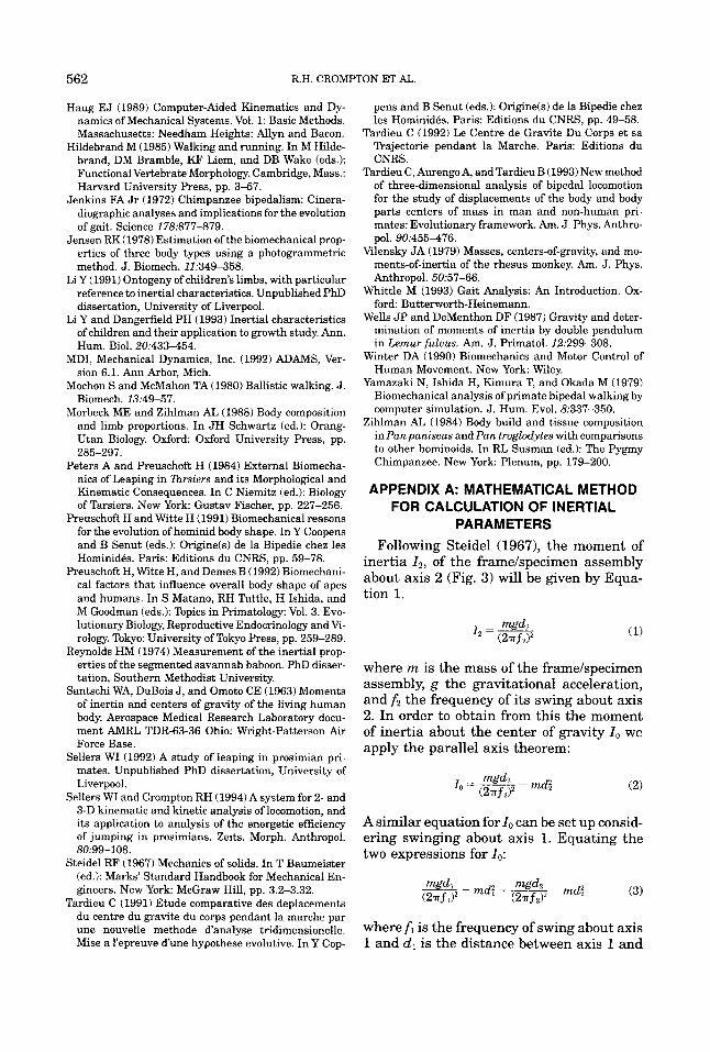
PARAMETERS Following Steidel (19671, the moment of
inertia 12, of the framelspecimen assembly about axis 2 (Fig. 3) will be given by Equa- tion l.
where m is the mass of the framelspecimen assembly, g the gravitational acceleration, and the frequency of its swing about axis 2. In order to obtain from this the moment of inertia about the center of gravity I. we apply the parallel axis theorem:
A similar equation for I. can be set up consid- ering swinging about axis 1. Equating the two expressions for I,,:
where f i is the frequency of swing about axis 1 and d, is the distance between axis 1 and
INERTIAL PROPERTIES OF PRIMATES 563
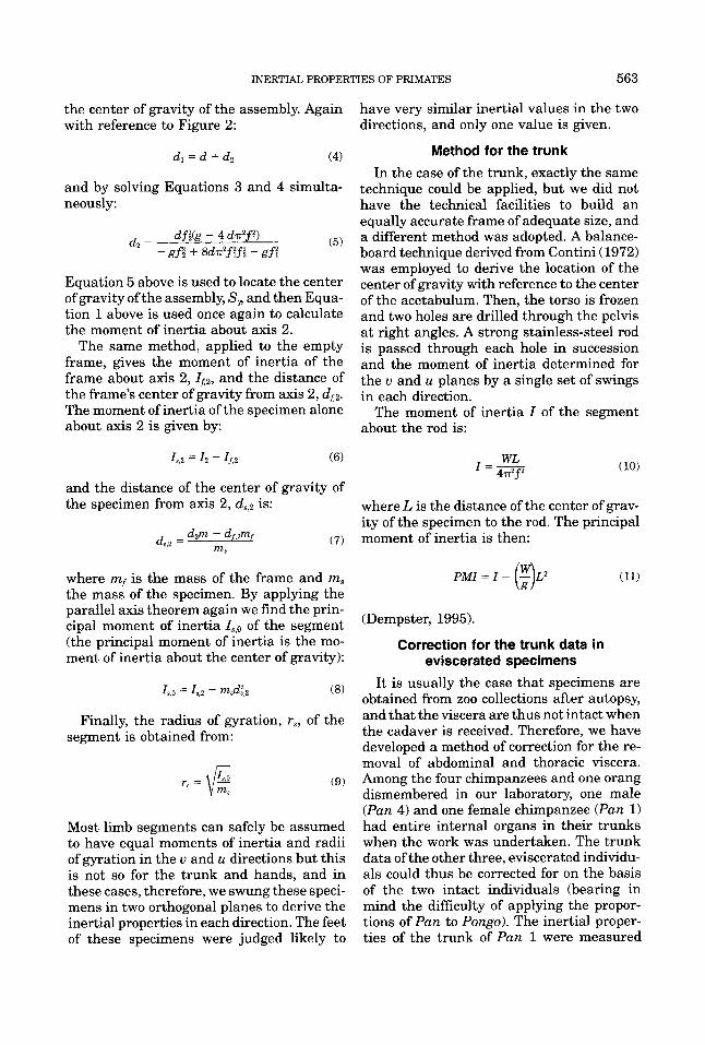
the center of gravity of the assembly. Again with reference to Figure 2:
have very similar inertial values in the two directions, and only one value is given.
and by solving Equations 3 and 4 simulta- neously:
(5)
Equation 5 above is used to locate the center of gravity of the assembly, S , and then Equa- tion l above is used once again to calculate the moment of inertia about axis 2.
The same method, applied to the empty frame, gives the moment of inertia of the frame about axis 2, I f 2 , and the distance of the frame's center of gravity from axis 2, df2. The moment of inertia of the specimen alone about axis 2 is given by:
df& - 4 d n ' f f ) - gfi + 8 d d f ?fl + gf?
d2 =
Method for the trunk In the case of the trunk, exactly the same
technique could be applied, but we did not have the technical facilities to build an equally accurate frame of adequate size, and a different method was adopted. A balance- board technique derived from Contini (1972) was employed to derive the location of the center of gravity with reference to the center of the acetabulum. Then, the torso is frozen and two holes are drilled through the pelvis at right angles. A strong stainless-steel rod is passed through each hole in succession and the moment of inertia determined for the u and u planes by a single set of swings in each direction.
The moment of inertia I of the segment about the rod is:
and the distance of the center of gravity of the specimen from axis 2, d,,2 is: where L is the distance of the center of grav-
ity of the specimen to the rod. The principal moment of inertia is then: d,,z = dzm - df,'rnf (7) m,
where mf is the mass of the frame and m, PMI = I - (F)Lz (11) the mass of the specimen. By applying the parallel axis theorem again we find the prin- cipal moment of inertia I,,o of the segment (the principal moment of inertia is the mo- ment of inertia about the center of gravity):
(Dempster, 1995).
Correction for the trunk data in eviscerated specimens
I,,o = 10 - m&z (8)
Finally, the radius of gyration, r,, of the segment is obtained from:
Most limb segments can safely be assumed to have equal moments of inertia and radii of gyration in the u and u directions but this is not so for the trunk and hands, and in these cases, therefore, we swung these speci- mens in two orthogonal planes to derive the inertial properties in each direction. The feet of these specimens were judged likely to
It is usually the case that specimens are obtained from zoo collections after autopsy, and that the viscera are thus not intact when the cadaver is received. Therefore, we have developed a method of correction for the re- moval of abdominal and thoracic viscera. Among the four chimpanzees and one orang dismembered in our laboratory, one male (Pan 4) and one female chimpanzee (Pan 1) had entire internal organs in their trunks when the work was undertaken. The trunk data of the other three, eviscerated individu- als could thus be corrected for on the basis of the two intact individuals (bearing in mind the difficulty of applying the propor- tions of Pan to Pongo). The inertial proper- ties of the trunk of Pan 1 were measured
564 R.H. CROMPTON ET AL.
three times (whole trunk, trunk with abdom- inal organ removed, and trunk with viscera removed), and these data were then used to calculate the trunk parameters ofPan 2, Pan 3, and the single Pongo.
For mass, it has been assumed that the mass ratio of the trunk without internal or- gans, (T'), over the intact trunk is the same in each individual. Based on this assump- tion, there is a relationship:
(12)
For the center of gravity, we assumed that the distance between the center of gravity of the internal organs (CG') and the hip joint in ratio to the trunk length is the same in each individual. This ratio was estimated, on the basis of Pan 1, as 40.8%. Then from the relationship:
T'Pm1 - T o t h e r
TPANI Tother
MiCG, + 0.408 M2 = M X CG (13)
where M I is the mass of the trunk without internal organs, CG, is the center of gravity of the trunk without the internal organs, and M2 is the mass of the internal organs themselves, the center of gravity (CG) of the trunk in question can be calculated.
For the radius of gyration (RG), the situa- tion is more complicated, and no logical rela- tion can be derived. We thus had to assume that the ratio of the RG of the whole trunk over the RG of the trunk without the internal organs was the same in all specimens as it was in Pan 1.
center of gravity will be exactly half-way along (50% of its length), its radius of gyra- tion will be 29.5% of its length, and its mass 0.707 kg. Parameters a, b, c, and k will have the following values: a = 0, b = 0, c = 0.032 = 0.0009, and k = 1. It can be mathe- matically modelled:
Then if there is a segment with length = 0.25 m, radius of gyration 31.7% of its length, its center of gravity located at 51.4% of its length, starting from its proxi- mal end, and a mass of 3.4 kg, we can model it by a solid of revolution (Fig. 1A) with the same length, a base diameter of 0.04 m and a radius at a given point of:
d0.003 z + 0.004
where z is the distance from the point to the base plane. In this case k = 1, a = 0, b = 0.003, and c = 0.004.
In the most complete case, when parame- ter a # 0, the outline of the solid of revolu- tion can be either convex or concave. Ifa < 0, the outline is more likely to be convex (Fig. lA), representing a smaller radius of gyra- tion, but if a > 0, the outline is concave, rep- resenting a larger radius of gyration. For segments of circular cross section, the mass of the segment is then:
Method of constructing models we then first create a Column-shaPed
model (Fig. 1). Each cross section of the col- umn is an ellipse, and the long axis of the ellipse is:
L L
m = ~p q2dz = r p (az2 + bz + c ) s s u = -\/az2 + bz + c (14)
n n
= r r p ( + a ~ 3 + 5 t ~ 2 + + L )
(18) 1 where z is the height of the given cross sec-
tion and its short axis:
u = ku (15)
For example, in a bar of length 0.25 m, diam- eter 0.06 m, and mass density 1 g/cm3, its
where p is the mass density and L the seg- ment length, and q is the radius of the solid
INERTIAL PROPERTIES OF PRIMATES 565
of revolution. The center of gravity along the z axis is then:
L
f zq2OI.z J -
c g = L = - 1 3aL2 + 6c + 4bL L 2 6c + 3bL + 2aL2 ( 1 9 )
0
The moment of inertia of the segment is: L
MI = p a J (0.25q4 + z2q2)dz (20) 0
curve u in Equation 14 may be estimated by measuring the diameter of circular segments or, should the segment appear elliptical, the long and short diameters, at a minimum of three locations of known distance along the segment, and fitting a curve to their radii, as shown in Figure 1A. For a limb segment such as upper arm or forearm, where the cross section tends to be circular in primates, the inertial properties can be estimated (us- ing with the model) by seven linear measure- ments. By measuring the values of diame- ters zl, and ul, z2, and u2, 23, and us, and length L, the model parameters a, b, and c can be estimated, for each curve as:
and the moment of inertia about the center of gravity (that is, the principal moment of inertia, PMI) is: P
(23) a = zlua - z3u: - z2u; - Z l U l + z*u? + z3u;
PMI = MI - cg2m (21) where the dummy variable p is:
and the radius of gyration can be derived using Equation 9. Then, there is a rela-
p - 2123~ - zg32 + zg? - 2912 + 29222 - zlz?
2:ua - z?u% - zau? + zau; - z;u; + u:2;
(24)
n (25) tionship:
b = r
MI cr = cg2 + rg2 = - m and 10b2L2 + 30c2 + 2 k L 4 + 30bL3 + 40cL2 (33\
Solving these simultaneous equations about m, CG, and cr gives us the values of a, b, and c. The parameters for the elliptical cross section model are obtainable in a similar way. In this case, there are four unknown variables in the equation groups, namely a, b, c, and k, which are to be calculated from m, CG, crum and cruu. Thus, if the parameter a in an equation is positive, the model will have a relatively large radius of gyration, and vice versa. If both a and b are zero, the model is a column with radius equal to the square root of c. The square root of c also represents the radius of the proximal end of a model with any given value for a and b.
Estimation of mass distribution in intact
If the segment is elliptical, k is estimated as the mean of the ratios of the radii in the u and u direction at each cross section (ulIul, uz/uz, and u&J. If it is circular, K = 1. From the parameters a, b, c, and k and the mea- surement L, we can calculate the inertial characteristics of any segment with an ellip- tical or circular cross section:
1 6 Mass = - p a kL (3bL + 6c + 2aL2) (27)
14bL + 6c + 3aL2 2 3bL + 6c + 3aL2 Center of gravity = - (28 )
and/or living specimens Moment of inertia of u-u axis While inertial properties can always be = p" + +L3 1 + -ka2L5 1 + -kc2L 1 (29)
most accurately determined by dissection 3 20 4 techniques, the properties Of segments may + -kcaL3 1 + -kaL5 1 + -kbL4 1 + -kcbL2 1 + also be derived non-invasively, since the 6 5 4 4
566 R.H. CROMPTON ET AL.
Moment of inertia of u-u axis APPENDIX 0: FORTRAN 90 SOURCE 1 1 CODE FOR CALCULATION OF INERTIAL 5 4 PROPERTIES OF LIVING SUBJECTS + - k d 5 + -kbL4 (30)
where p is a suitable value for the density of the segment. Values could be substituted for each segment from the figures in Table 1, if no cadavers at all are available. The sum of all segment masses should be course closely approximate the weighed mass of the animal!
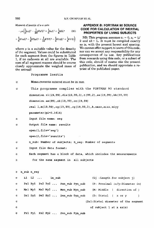
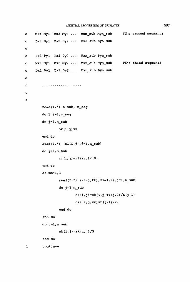
Programme I n e r t i a
NB: This program assumes z1 = 0, z2 = W 2 and 23 = L. It must be compiled exactly as is, with the present layout and spacing. We cannot offer support to users of this code, nor can we accept any responsibility for any consequences of its use. Any publications from research using this code, or a subset of this code, should of course cite the present publication, and we should appreciate a re- print of the published paper.
C Measurements entered must be in mm
C T h i s programme complies w i t h the FORTRAN 90 s t a n d a r d
dimension z1(19,99) ,dia(19,99,3) ,t (99,2) ,aa(19,99) ,bb(19,99)
C
C
dimension am(99) , sk (19,99) , cc (19, 99) real l,m(19,99) ,cg(19,99) ,rg(19,99,2) , k,mass,muxx,miyy parameter (pi=3.1416)
Input file name: seg
Output file name: results
open (1, file= ' seg ' ) open(Z,file='results')
C n-sub: Number of subjects; n-seg: Number of segments
C Input file data format:
C Each segment has a block of data, which includes the measurements
C for the same segment in all subjects
c n-sub n-seg
c L1 L2 ... Ln-sub (Lj :Length for subject j)
c Pxl Pyl Px2 Py2 ... Pxn-sub Pyn-sub (P: Proximal Ix/y:Diameter in)
c Mxl My1 Mx2 My2 ... Mxn-sub Myn-sub (M: Middle I direction of )
c Dxl Dyl Dx2 Dy2 ... Dxn-sub Dyn-sub (D: Distal I x or y 1
C (Dx1:Distal diameter of the segment
C of subject 1 at x axis)
c Pxl Pyl Px2 Py2 ... Pxn-sub Pyn-sub
INERTIAL PROPERTIES OF PRIMATES 567
C
C
C
C
C
C
C
C
C
C
1
Mxl My1 Mx2 My2 ... Mxn-sub Myn-sub (The second segment)
Dxl Dyl Dx2 Dy2 ... Dxn-sub Dyn-sub
pxl Pyl Px2 Py2 ... Pxn-sub Pyn-sub
Mxl My1 Mx2 My2 . .. Mxn-sub M y n - m b (The third segment)
Dxl Dyl Dx2 Dy2 ... Dxn-sub Dyn-sub
...................
read (1, *) n-sub, n-seg
do 1 i=l,n-seg
do j=l,n-sub
sk (i, j) -0
end do
read(l,*) (zl(i,j) , j=l,n-sub) do j=l,n-sub
zl(i,j)=zl(i,j)/lO.
end do
do m=1,3
read (1, *) ( (t (j I kk) I kk=l, 2) , j=1, n-sub) do j =l , n-sub
sk (i, j)=sk (it j)+t (j , 2) /t (j , 1) dia (i, j ,nun) =t (j , 1) /2.
end do
end do
do j = 1, n-s ub
sk(i,j)=sk(i, j)/3
end do
cant inue
568 R.H. CROMPTON ET AL.
do 21 i=l,n-seg
do 21 j=l,n-sub
1=zl (i, j)
yl=dia (i, j , 1) **2 y2=dia (i, j , 2) **2 y3=dia (i, j ,3) **2
cc (i, j ) =yl
aa (i, j)=-2/1**2* (2 .*y2-yl-y3)
bb (i, j ) = (-y3+4. *y2-3*yl) /1
c=cc(i, j)
b=bb(i, j)
a=aa(i, j)
k=sk (i, j)
t4 = 1**2
mass = pi*k*1*(3*b*1+6*~+2*a*t4)/6
m ( i , j)=mass
tl = b*l
t3 = 6*c
t4 = 1**2
t5 = a*t4
cg(i, j) = 1* (4*tl+t3+3*t5) / (3*tl+t3+2*t5) /2
tl = 1**2
t2 = tl**2
t5 = k**2
t6 = c*tl
t10 = c**2
t18 = b*tl*l
t23 = a**2
t21 = b**2
~xx=k~pi*l*(24*a*t2+2O*a*t5' t6+3O*t lO*t5+3O*c*t5*b*l+
$ 15*a*t5*t18+30*t18+6*t5*t23*t2+lO*t27*t5*tl+4O*t6)/120
569 INERTIAL PROPERTIES OF PRIMATES
tl = b**2
t2 = 1**2
t5 = c**2
tl = a**2
t8 = t2**2
t12 = b*t2*1
t20 = c*t2
~~k*pi*l*(10*tl*t2+30+t5+6*t7*t8+15*a*tl2+3O*c*b*l+
$ 2 4 * a f t 8 + 2 0 * a * t 2 0 + 3 0 * t ~ ~ + ~ ~ * t 2 ~ ) / ~ ~ ~
rg(i, j,l)= sqrt((mixx-~g(i,j)**2*m(i,j))/m(i,j))/~*~~~.
rg(i, j,2)= sqrt((miyy-cg(i, j)**2*m(i,j))/m(i,j))/l*loO.
cg(i, j)- cg(i, j)/l*lOO.
21 continue
writc(2,lE)
write(2,'(80(1H-)) ' )
do 41 i=l,n-seg
write(2,*) 'Segment NO.',^
do j=l,n-sub
write(2,8) sk(i,j),zl(i,j),m(i,j),cg(i,j),rg(i/j/l)/rg(i,j,2)/
$ aa(i, j) ,bb(i, j) ,cc(i, j)
end do
write(2,') ' '
41 continue
write(2, ' (80(1H-)) ' )
write(2,*) ' write(2,*) ' write (2, *) ' K: The ratio of the diameters of y/x for the m
lodel'
write(2,*)' Length: Length of the segment model, same as the in
lput '
write(2,*) ' Mass: Mass of the model, an estimation for the li
lmb segment'
570 R.H. CROMPTON ET AL.
write (2 , *) ' CG: Centre of mass along the long (z) axis'
write(2,*) RGxx: Radius of gyration for xx plane'
write(2,*) RGyy: Radius of gyration for yy plane'
write (2, * ) ' a: Parameter a in model v=sqrt (a*u*u+b*u+c)
write (2, * ) ' b: Parameter b in model v=sqrt(a*u*u+b*u+c)'
write (2, *) c: Parameter c in model v=sqrt (a*u*u+b*u+c) I
a format(2x,f7.4,f7.1,f9.2,3f8.2,4xlf11.7,f~.3,f6.2)
18 format (2xI7H K, 7H Length, 9H Mass, 8H CG,8H RGxx,
1 8H RGyy14x,llH a, 8H b, 6H C)
end