Embed Size (px)
Citation preview
Gregor v. Bochmann, University of Ottawa
Based on Powerpoint slides by Gunter Mussbacherwith material from:
K.E. Wiegers, D. Leffingwell & D. Widrig, M. Jackson, I.K. Bray, B. Selic,Volere, Telelogic, D. Damian, S. Somé 2008, and D. Amyot 2008-2009
Behavioral Modeling
SEG3101 (Fall 2010)
2SEG3101 (Fall 2010). Functional Modeling
Table of Contents• An introduction to modeling is already given in the slides on
“Introduction to Requirements Analysis and Specification”
• Structural modeling is discussed in separate slides.
• Here we discuss a four selected approaches for modeling behavioral aspects of requirements. For the last three approaches, we discuss the UML notations in detail.
• Structured Analysis• UML Activity Diagrams, also Use Case Maps (see separate slides)• UML Sequence Diagrams• UML State Diagrams
• We also give an overview of UML version 2 and discuss for each of these approaches, how a model can be used for analysis (validation, verification – functional and non-functional) and implementation development.
• Get the habit of analysis – analysis will in time enable synthesis to become your habit of mind.1[1] Frank Lloyd Wright (1867 - 1959)

3SEG3101 (Fall 2010). Functional Modeling

Structured Analysis
5SEG3101 (Fall 2010). Functional Modeling
Structured Analysis• Data-oriented approach
• Based on analysis of information flow• Models
• Dataflow Diagram (DFD) – flow of information in system• Entity Relationship Diagrams (ERD) – describe data• Data Dictionary (DD) – define all data elements• State Diagram – describe state-based behavior
• Mainly used for information systems• Extensions have been developed for real-time systems
• Analysis consists of modeling current system (can be a manual system)
• New system derived from understanding current system• What if there is no current system?
Introduction Structured Analysis OO Analysis Problem Frames State Machine-Based Analysis Triage/Prioritization
6SEG3101 (Fall 2010). Functional Modeling
Popular Approaches (at least once upon a time…)Structured Analysis is historically important. Here are some of
the more popular versions:
• Structured Analysis and Design Technique (SADT) by Doug Ross
• Structured Analysis and System Specification (SASS) by Yourdon and DeMarco
• Structured System Analysis (SSA) by Gane et Sarsan• Structured Systems Analysis and Design (SSADM)• Structured Requirements Definition (SRD) by Ken Orr• Structured Analysis / Real Time (SA/RT) by Ward and Mellor• Modern Structured Analysis by Yourdon
Introduction Structured Analysis OO Analysis Problem Frames State Machine-Based Analysis Triage/Prioritization
7SEG3101 (Fall 2010). Functional Modeling
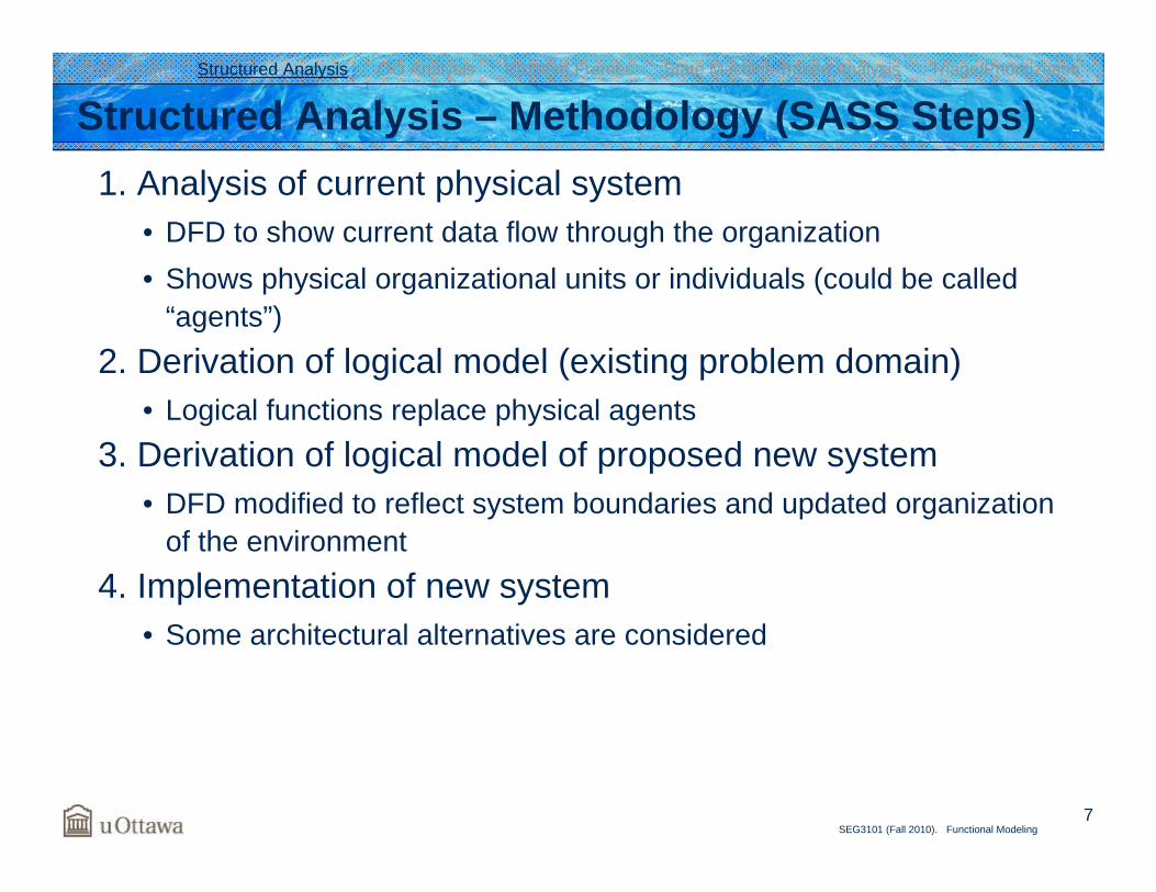
Structured Analysis – Methodology (SASS Steps)1. Analysis of current physical system
• DFD to show current data flow through the organization• Shows physical organizational units or individuals (could be called
“agents”)2. Derivation of logical model (existing problem domain)
• Logical functions replace physical agents3. Derivation of logical model of proposed new system
• DFD modified to reflect system boundaries and updated organization of the environment
4. Implementation of new system• Some architectural alternatives are considered
Introduction Structured Analysis OO Analysis Problem Frames State Machine-Based Analysis Triage/Prioritization
8SEG3101 (Fall 2010). Functional Modeling
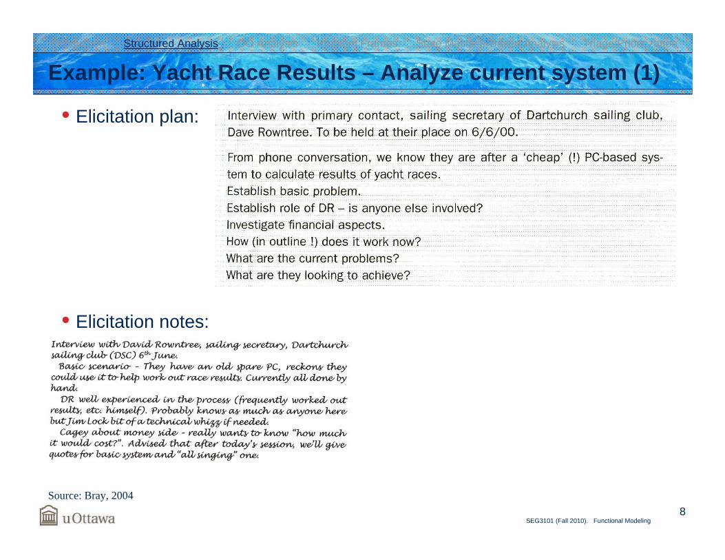
Example: Yacht Race Results – Analyze current system (1)
• Elicitation plan:
• Elicitation notes:
Introduction Structured Analysis OO Analysis Problem Frames State Machine-Based Analysis Triage/Prioritization
Source: Bray, 2004
9SEG3101 (Fall 2010). Functional Modeling
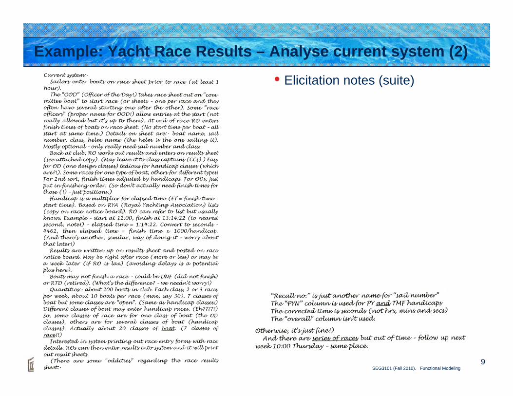
Example: Yacht Race Results – Analyse current system (2)
• Elicitation notes (suite)
10SEG3101 (Fall 2010). Functional Modeling
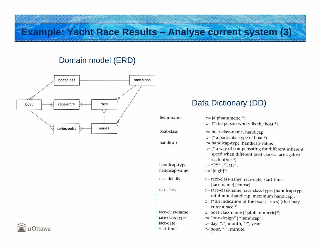
Example: Yacht Race Results – Analyse current system (3)
Domain model (ERD)
Data Dictionary (DD)
11SEG3101 (Fall 2010). Functional Modeling
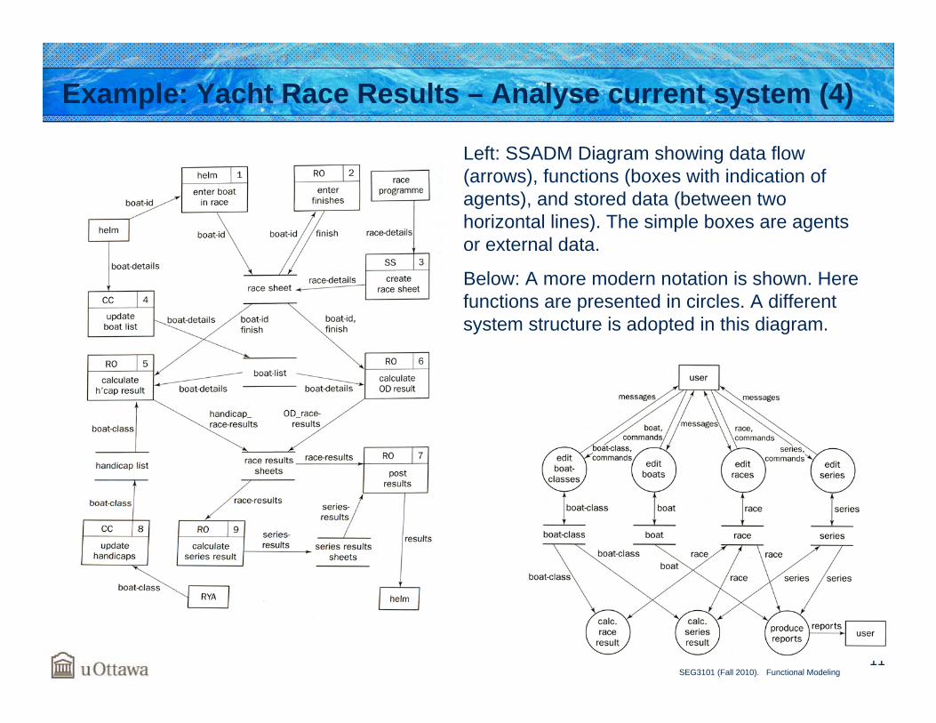
Example: Yacht Race Results – Analyse current system (4)
Left: SSADM Diagram showing data flow (arrows), functions (boxes with indication of agents), and stored data (between twohorizontal lines). The simple boxes are agents or external data.
Below: A more modern notation is shown. Herefunctions are presented in circles. A differentsystem structure is adopted in this diagram.
12SEG3101 (Fall 2010). Functional Modeling
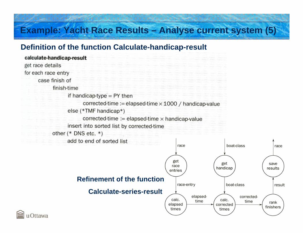
Example: Yacht Race Results – Analyse current system (5)
Definition of the function Calculate-handicap-result
Refinement of the function
Calculate-series-result
13SEG3101 (Fall 2010). Functional Modeling
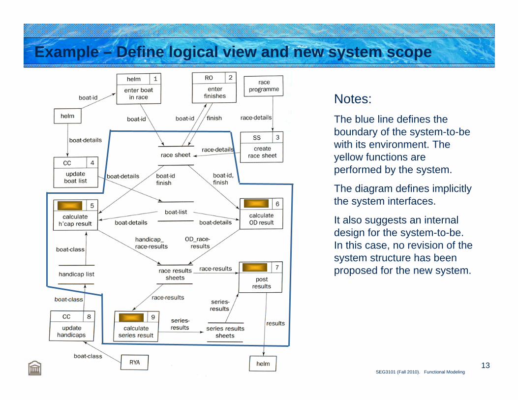
Example – Define logical view and new system scope
Notes:The blue line defines the boundary of the system-to-bewith its environment. The yellow functions are performed by the system.
The diagram defines implicitlythe system interfaces.
It also suggests an internaldesign for the system-to-be. In this case, no revision of the system structure has been proposed for the new system.
14SEG3101 (Fall 2010). Functional Modeling
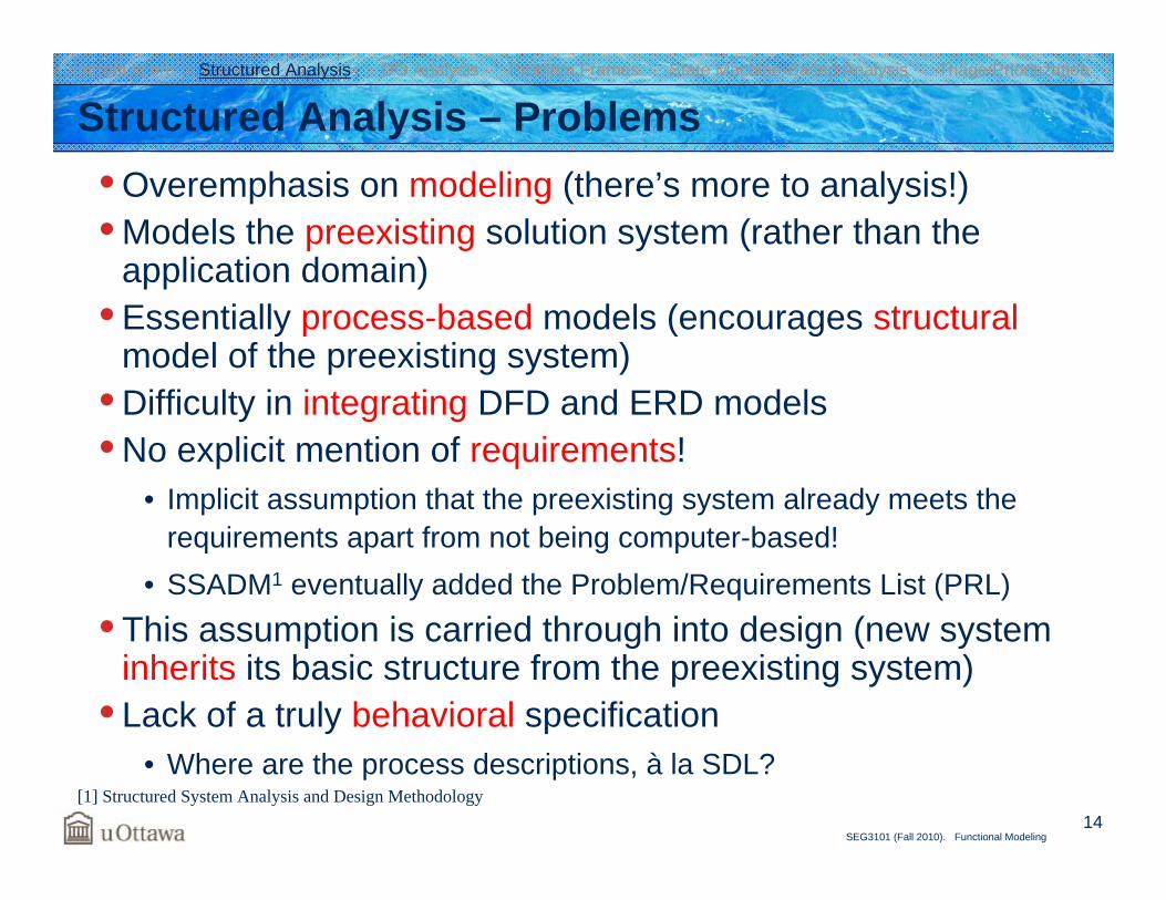
Structured Analysis – Problems• Overemphasis on modeling (there’s more to analysis!)• Models the preexisting solution system (rather than the
application domain)• Essentially process-based models (encourages structural
model of the preexisting system)• Difficulty in integrating DFD and ERD models• No explicit mention of requirements!
• Implicit assumption that the preexisting system already meets the requirements apart from not being computer-based!
• SSADM1 eventually added the Problem/Requirements List (PRL)• This assumption is carried through into design (new system
inherits its basic structure from the preexisting system)• Lack of a truly behavioral specification
• Where are the process descriptions, à la SDL?
Introduction Structured Analysis OO Analysis Problem Frames State Machine-Based Analysis Triage/Prioritization
[1] Structured System Analysis and Design Methodology

Introduction to the Unified Modeling Language (UML)
16SEG3101 (Fall 2010). Functional Modeling
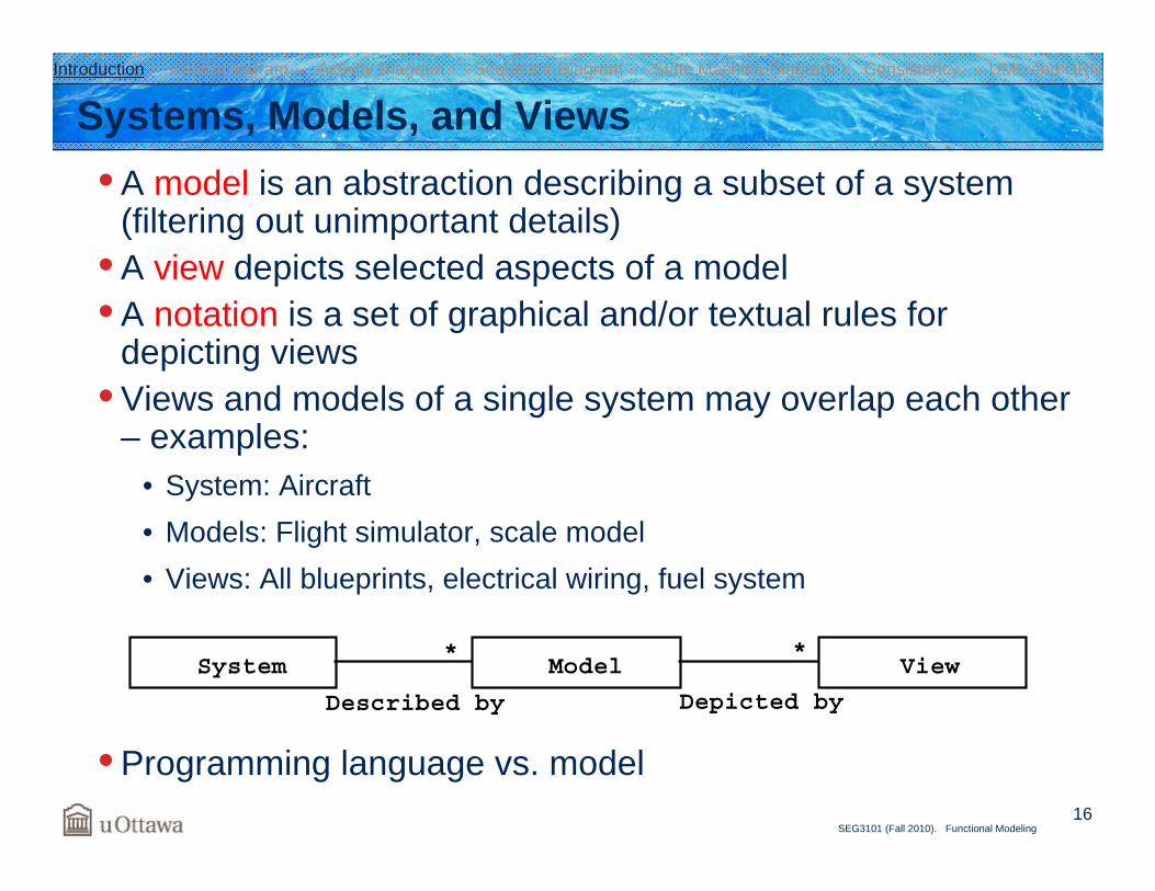
Systems, Models, and Views• A model is an abstraction describing a subset of a system
(filtering out unimportant details)• A view depicts selected aspects of a model• A notation is a set of graphical and/or textual rules for
depicting views• Views and models of a single system may overlap each other
– examples:• System: Aircraft• Models: Flight simulator, scale model• Views: All blueprints, electrical wiring, fuel system
• Programming language vs. model
System Model View**
Depicted byDescribed by
Introduction Class Diagram Activity Diagram Sequence Diagram State Machine Diagram Consistency UML and URN
17SEG3101 (Fall 2010). Functional Modeling
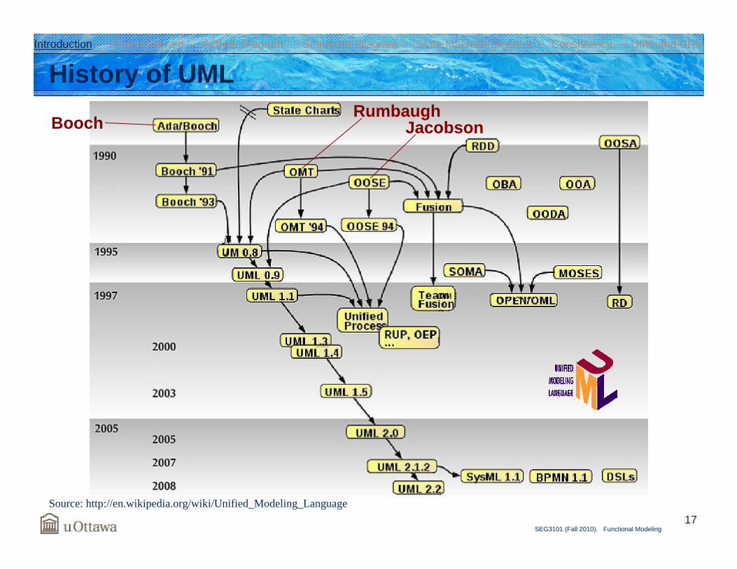
History of UML
Source: http://en.wikipedia.org/wiki/Unified_Modeling_Language
JacobsonRumbaugh
Booch
Introduction Class Diagram Activity Diagram Sequence Diagram State Machine Diagram Consistency UML and URN
18SEG3101 (Fall 2010). Functional Modeling
UML 2.x• Object Management Group (OMG) standard
• Version 2.0 released in 2005• Current version is 2.3 (May 2010)• http://www.omg.org/uml/
• Some key points (new in Version 2) • Restructuring of the metamodel
• Infrastructure (semantics) and superstructure (notation)
• New or modified diagrams• Simpler and more powerful profile mechanisms• Diagram exchange format (between UML tools)• OCL 2.0 (Object Constraint Language – for input/output assertions,
invariants, etc. (resembles first-order logic)
Introduction Class Diagram Activity Diagram Sequence Diagram State Machine Diagram Consistency UML and URN
19SEG3101 (Fall 2010). Functional Modeling
Thirteen Diagram Types in UML 2.x• Few changes
• Use case, object, package, deployment diagrams• Major improvements but less relevant to requirements
engineering• Component and communication (collaboration) diagrams
• Major improvements and interesting for requirements engineering
• State machine (integration of SDL as a profile), class, activity(complete re-write of the semantics), and sequence diagrams
• New • Timing, interaction overview, composite structure diagrams
Introduction Class Diagram Activity Diagram Sequence Diagram State Machine Diagram Consistency UML and URN
20SEG3101 (Fall 2010). Functional Modeling
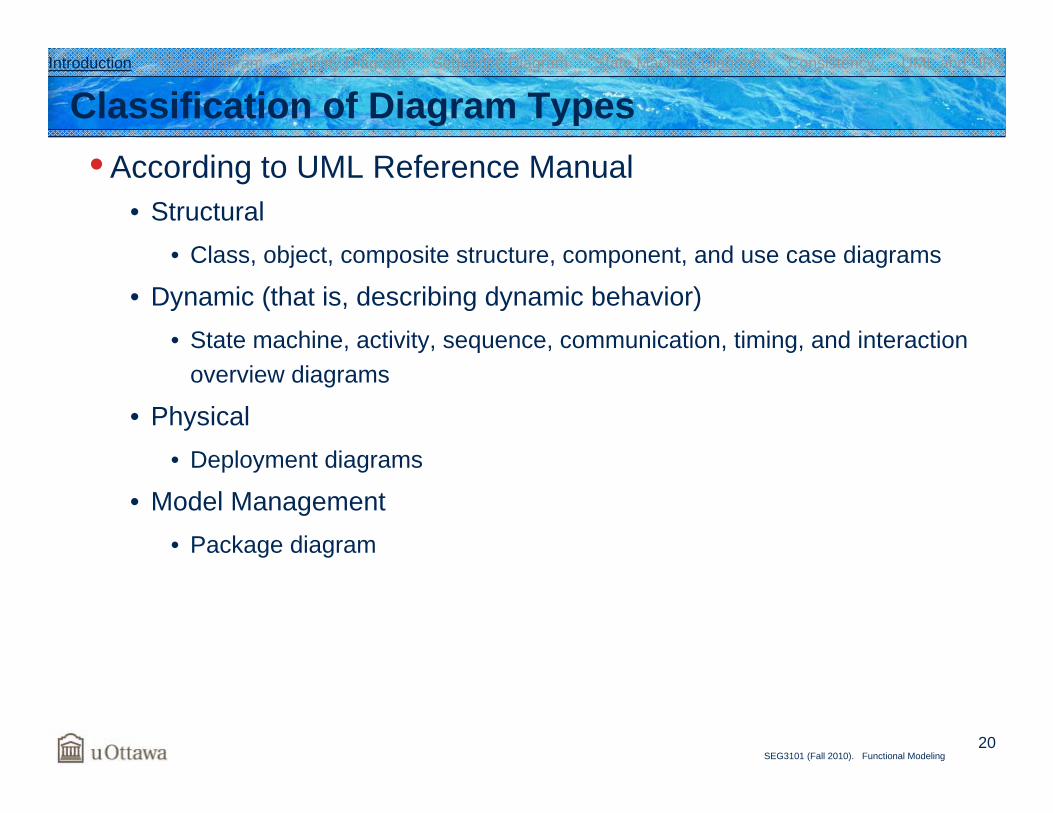
Classification of Diagram Types• According to UML Reference Manual
• Structural• Class, object, composite structure, component, and use case diagrams
• Dynamic (that is, describing dynamic behavior)• State machine, activity, sequence, communication, timing, and interaction
overview diagrams
• Physical• Deployment diagrams
• Model Management• Package diagram
Introduction Class Diagram Activity Diagram Sequence Diagram State Machine Diagram Consistency UML and URN
21SEG3101 (Fall 2010). Functional Modeling
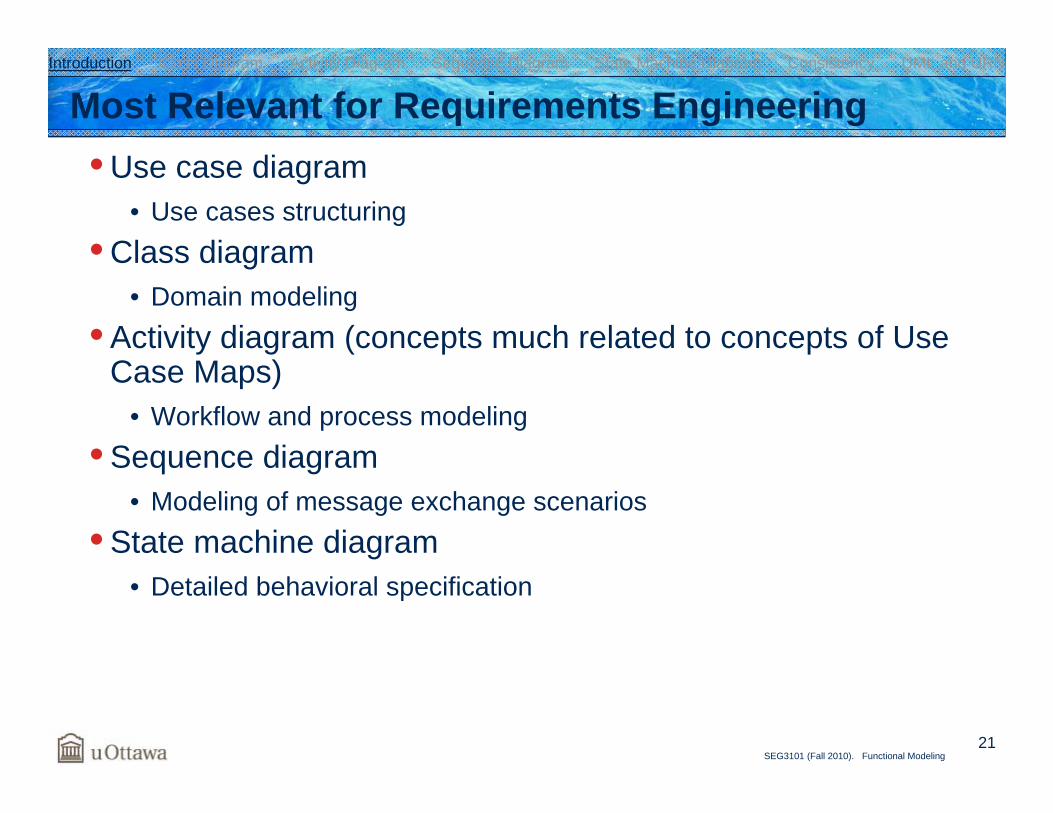
Most Relevant for Requirements Engineering• Use case diagram
• Use cases structuring• Class diagram
• Domain modeling• Activity diagram (concepts much related to concepts of Use
Case Maps)• Workflow and process modeling
• Sequence diagram• Modeling of message exchange scenarios
• State machine diagram• Detailed behavioral specification
Introduction Class Diagram Activity Diagram Sequence Diagram State Machine Diagram Consistency UML and URN

Activity Diagram
23SEG3101 (Fall 2010). Functional Modeling
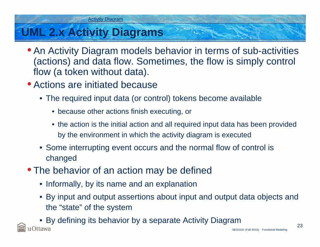
UML 2.x Activity Diagrams• An Activity Diagram models behavior in terms of sub-activities
(actions) and data flow. Sometimes, the flow is simply control flow (a token without data).
• Actions are initiated because• The required input data (or control) tokens become available
• because other actions finish executing, or
• the action is the initial action and all required input data has been provided by the environment in which the activity diagram is executed
• Some interrupting event occurs and the normal flow of control ischanged
• The behavior of an action may be defined• Informally, by its name and an explanation• By input and output assertions about input and output data objects and
the “state” of the system• By defining its behavior by a separate Activity Diagram
Introduction Class Diagram Activity Diagram Sequence Diagram State Machine Diagram Consistency UML and URN
24SEG3101 (Fall 2010). Functional Modeling
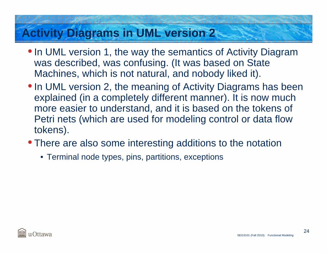
Activity Diagrams in UML version 2• In UML version 1, the way the semantics of Activity Diagram
was described, was confusing. (It was based on State Machines, which is not natural, and nobody liked it).
• In UML version 2, the meaning of Activity Diagrams has been explained (in a completely different manner). It is now much more easier to understand, and it is based on the tokens of Petri nets (which are used for modeling control or data flow tokens).
• There are also some interesting additions to the notation• Terminal node types, pins, partitions, exceptions
25SEG3101 (Fall 2010). Functional Modeling
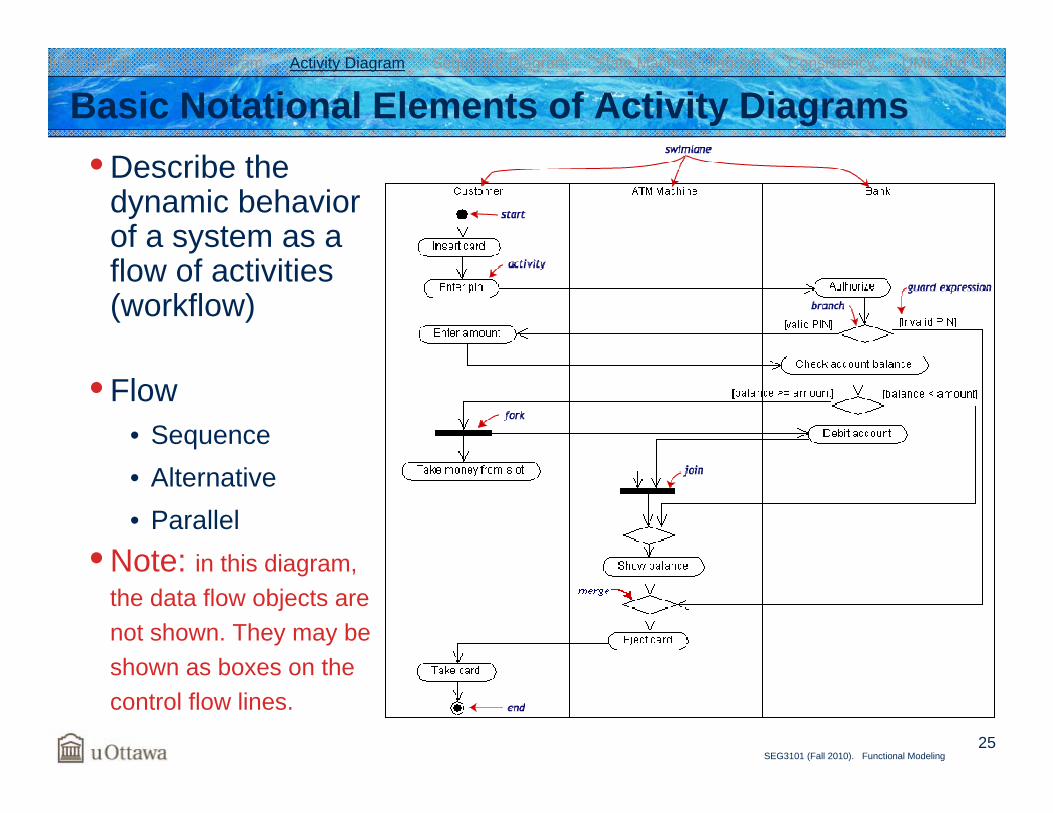
Basic Notational Elements of Activity Diagrams• Describe the
dynamic behavior of a system as a flow of activities (workflow)
• Flow• Sequence• Alternative• Parallel
• Note: in this diagram, the data flow objects are not shown. They may be shown as boxes on the control flow lines.
Introduction Class Diagram Activity Diagram Sequence Diagram State Machine Diagram Consistency UML and URN
26SEG3101 (Fall 2010). Functional Modeling
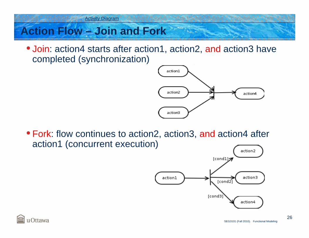
Action Flow – Join and Fork• Join: action4 starts after action1, action2, and action3 have
completed (synchronization)
• Fork: flow continues to action2, action3, and action4 after action1 (concurrent execution)
Introduction Class Diagram Activity Diagram Sequence Diagram State Machine Diagram Consistency UML and URN
27SEG3101 (Fall 2010). Functional Modeling
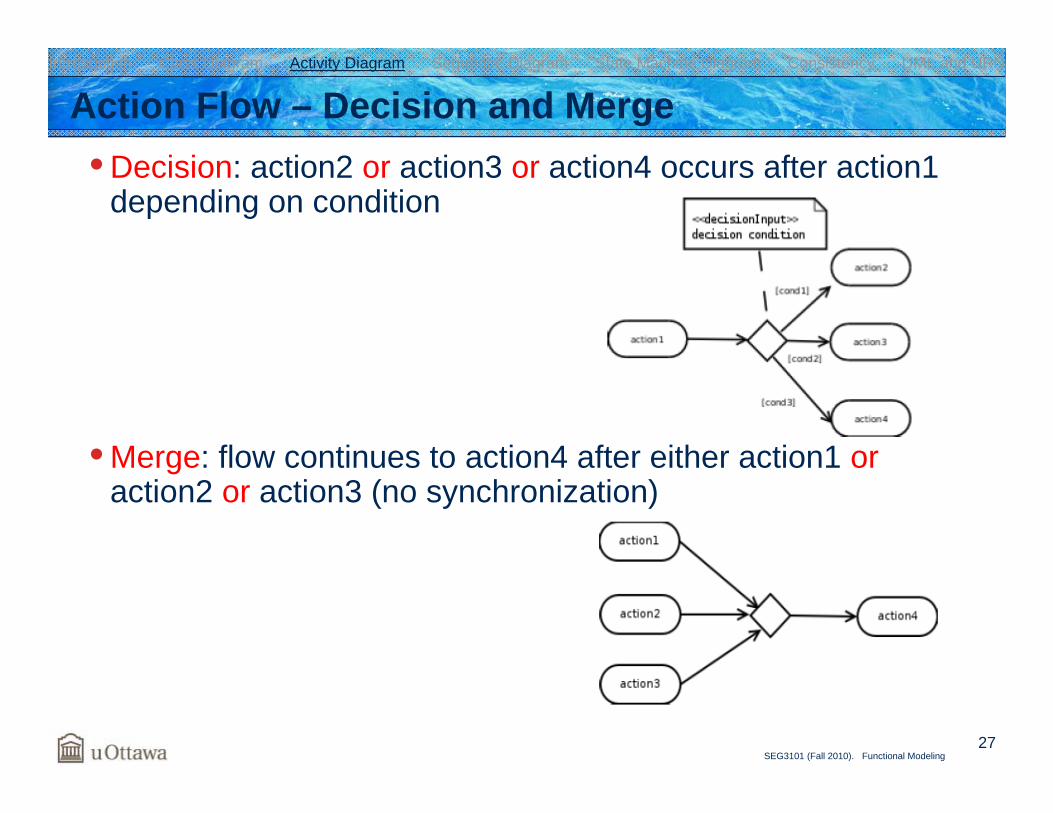
Action Flow – Decision and Merge• Decision: action2 or action3 or action4 occurs after action1
depending on condition
• Merge: flow continues to action4 after either action1 oraction2 or action3 (no synchronization)
Introduction Class Diagram Activity Diagram Sequence Diagram State Machine Diagram Consistency UML and URN
28SEG3101 (Fall 2010). Functional Modeling
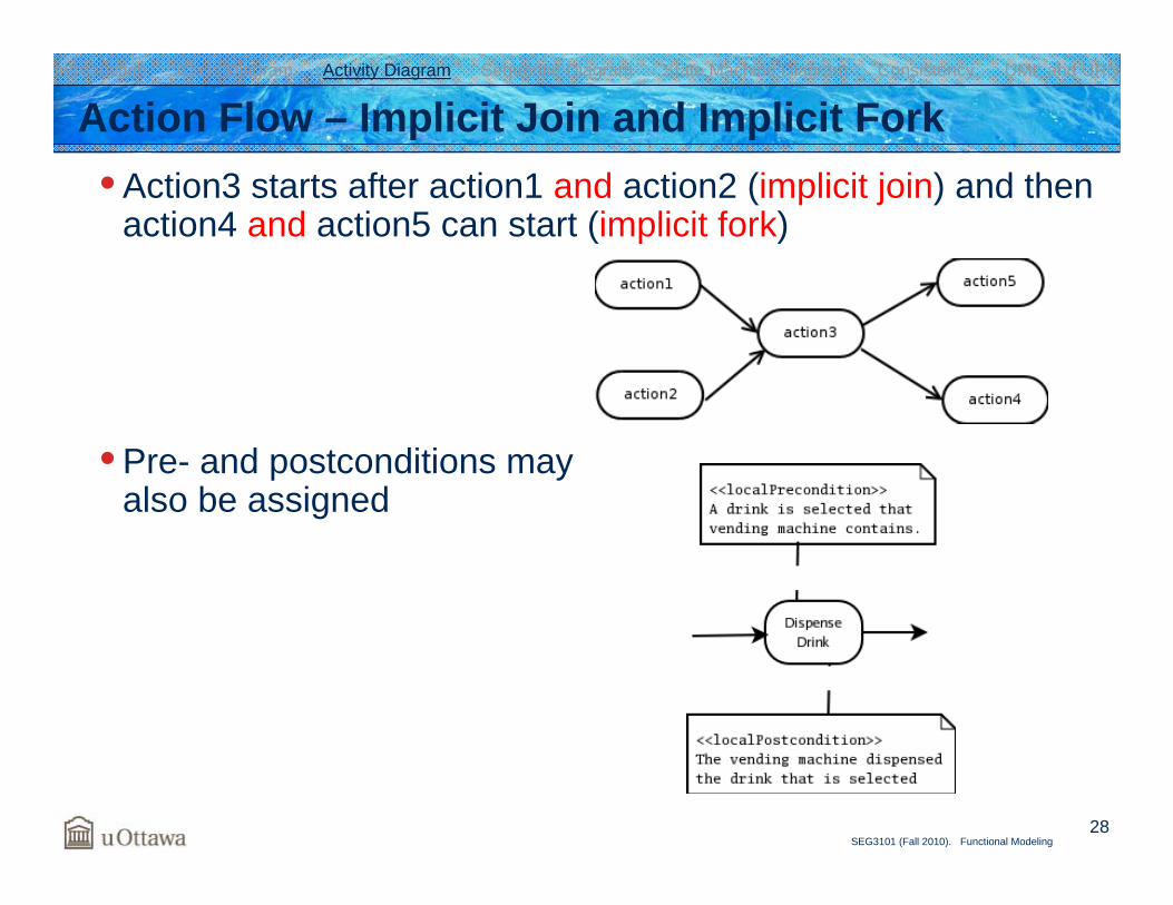
Action Flow – Implicit Join and Implicit Fork• Action3 starts after action1 and action2 (implicit join) and then
action4 and action5 can start (implicit fork)
• Pre- and postconditions may also be assigned
Introduction Class Diagram Activity Diagram Sequence Diagram State Machine Diagram Consistency UML and URN
29SEG3101 (Fall 2010). Functional Modeling
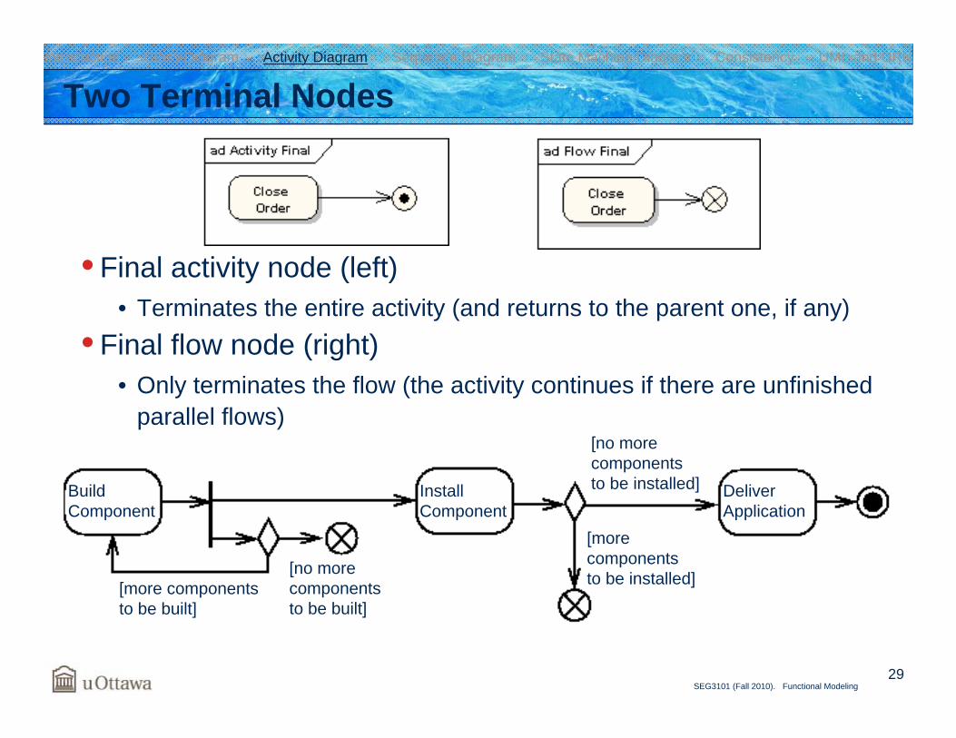
Two Terminal Nodes
• Final activity node (left)• Terminates the entire activity (and returns to the parent one, if any)
• Final flow node (right)• Only terminates the flow (the activity continues if there are unfinished
parallel flows)
BuildComponent
[more componentsto be built]
[no morecomponentsto be built]
InstallComponent
[no morecomponentsto be installed]
[morecomponentsto be installed]
DeliverApplication
Introduction Class Diagram Activity Diagram Sequence Diagram State Machine Diagram Consistency UML and URN
30SEG3101 (Fall 2010). Functional Modeling
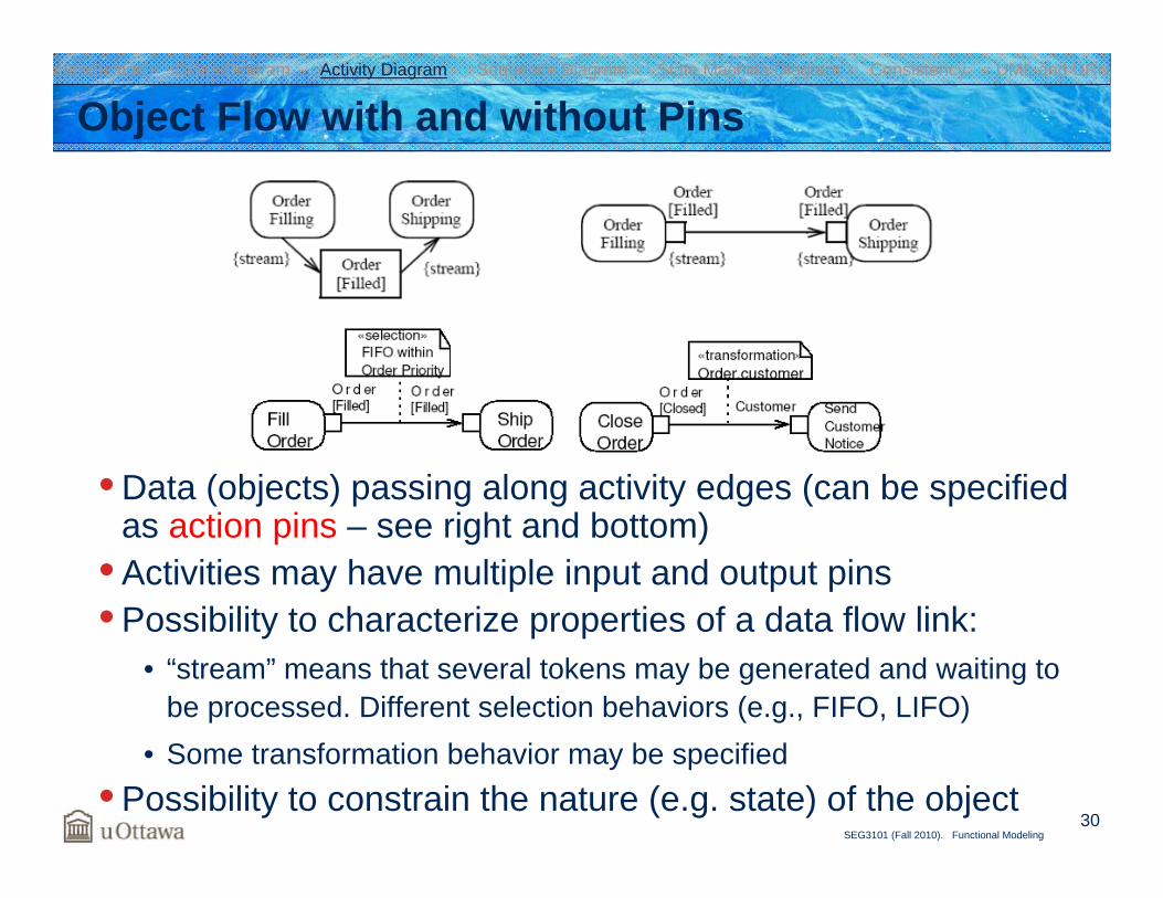
Object Flow with and without Pins
• Data (objects) passing along activity edges (can be specified as action pins – see right and bottom)
• Activities may have multiple input and output pins• Possibility to characterize properties of a data flow link:
• “stream” means that several tokens may be generated and waiting to be processed. Different selection behaviors (e.g., FIFO, LIFO)
• Some transformation behavior may be specified• Possibility to constrain the nature (e.g. state) of the object
Introduction Class Diagram Activity Diagram Sequence Diagram State Machine Diagram Consistency UML and URN
31SEG3101 (Fall 2010). Functional Modeling
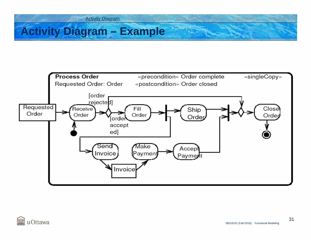
Activity Diagram – ExampleIntroduction Class Diagram Activity Diagram Sequence Diagram State Machine Diagram Consistency UML and URN
32SEG3101 (Fall 2010). Functional Modeling
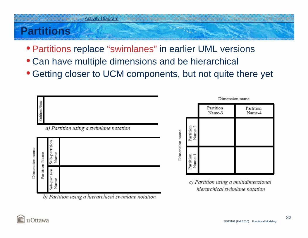
Partitions• Partitions replace “swimlanes” in earlier UML versions• Can have multiple dimensions and be hierarchical• Getting closer to UCM components, but not quite there yet
Introduction Class Diagram Activity Diagram Sequence Diagram State Machine Diagram Consistency UML and URN
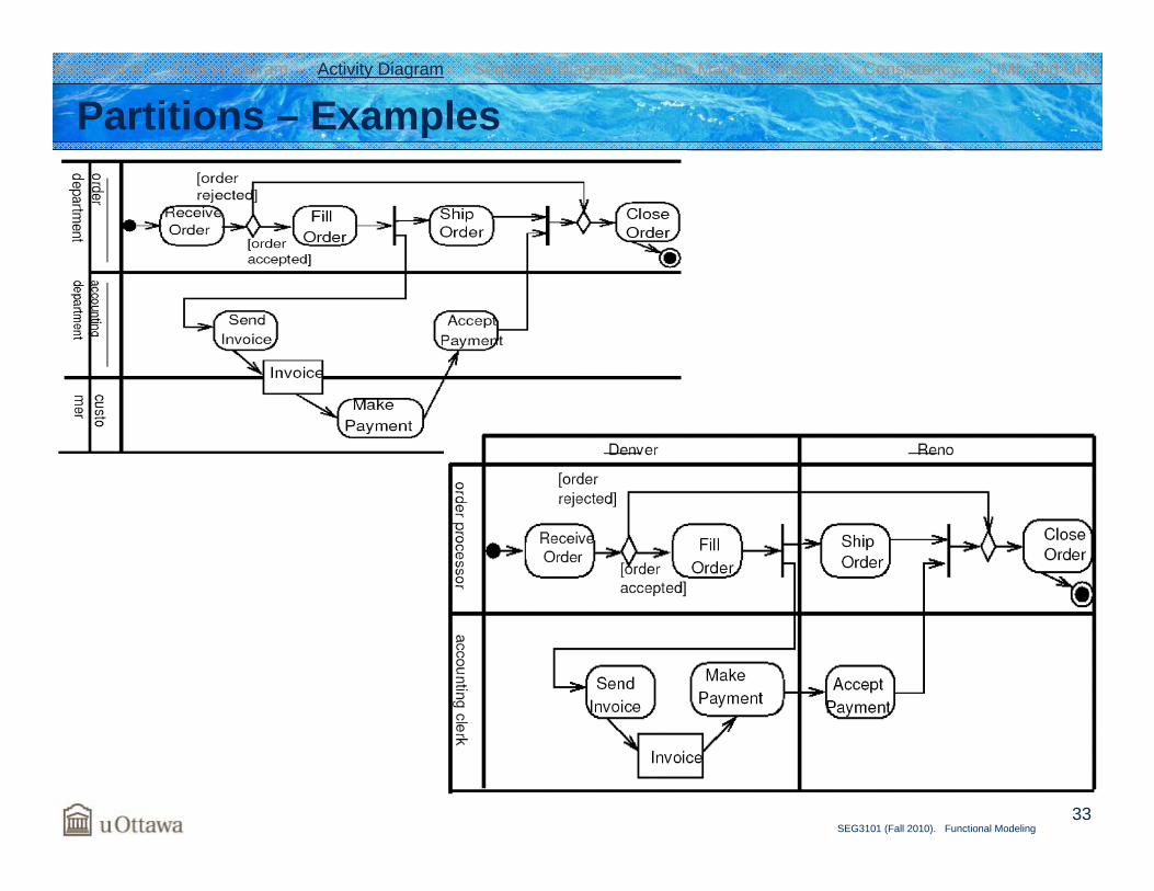
33SEG3101 (Fall 2010). Functional Modeling
Partitions – ExamplesIntroduction Class Diagram Activity Diagram Sequence Diagram State Machine Diagram Consistency UML and URN
34SEG3101 (Fall 2010). Functional Modeling
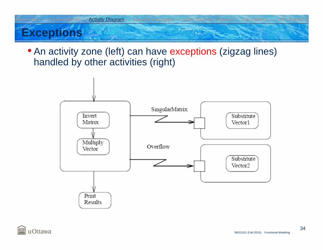
Exceptions• An activity zone (left) can have exceptions (zigzag lines)
handled by other activities (right)
Introduction Class Diagram Activity Diagram Sequence Diagram State Machine Diagram Consistency UML and URN
35SEG3101 (Fall 2010). Functional Modeling
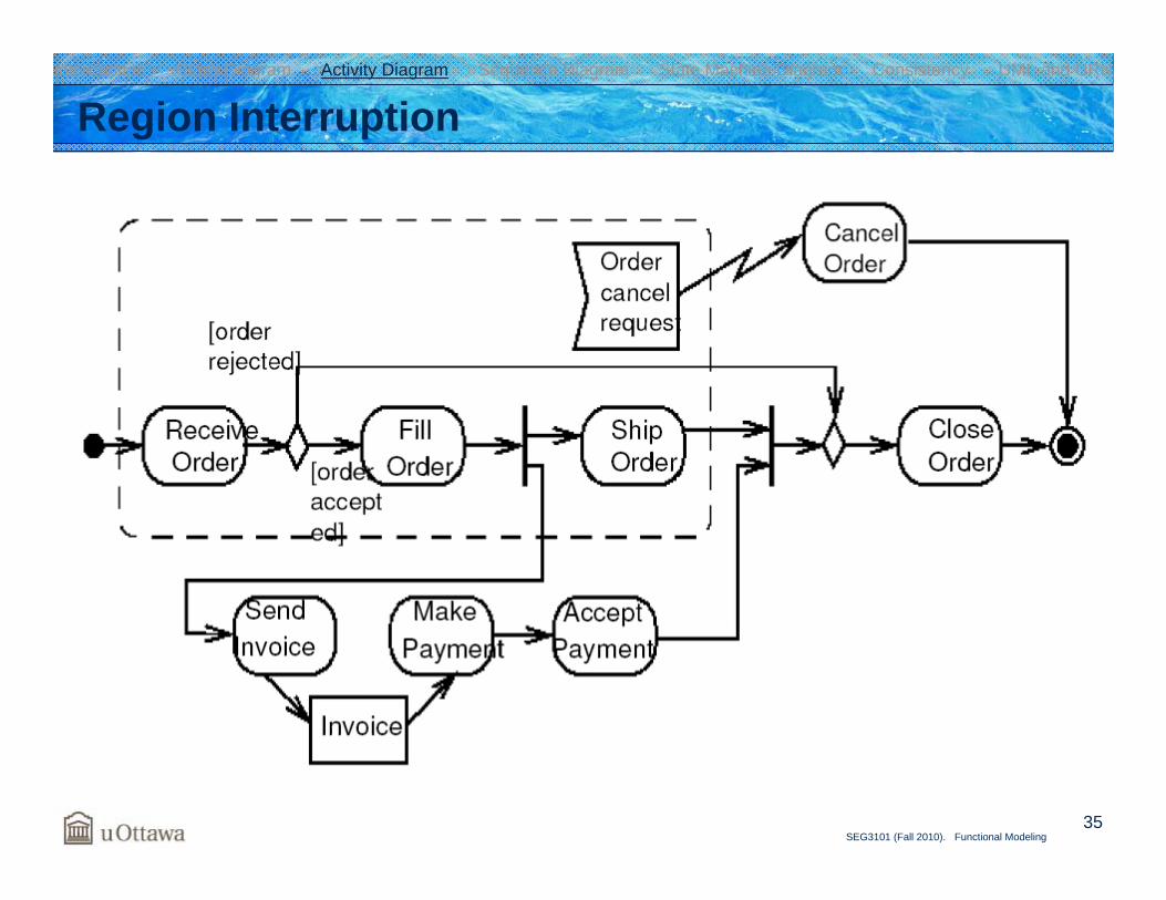
Region InterruptionIntroduction Class Diagram Activity Diagram Sequence Diagram State Machine Diagram Consistency UML and URN

UML and URN
37SEG3101 (Fall 2010). Functional Modeling
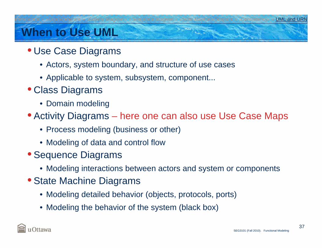
When to Use UML• Use Case Diagrams
• Actors, system boundary, and structure of use cases• Applicable to system, subsystem, component...
• Class Diagrams• Domain modeling
• Activity Diagrams – here one can also use Use Case Maps• Process modeling (business or other)• Modeling of data and control flow
• Sequence Diagrams• Modeling interactions between actors and system or components
• State Machine Diagrams• Modeling detailed behavior (objects, protocols, ports)• Modeling the behavior of the system (black box)
Introduction Class Diagram Activity Diagram Sequence Diagram State Machine Diagram Consistency UML and URN
38SEG3101 (Fall 2010). Functional Modeling
UCM or UML Activity Diagrams?• UCM and activity diagrams have many concepts in common
• Responsibility ↔ action• Start/end points• Alternatives (fork / join)• Concurrency (fork / join)• Stub / plug-in ↔ action / sub-activity diagram• Association between elements and components / partition• Both may represent operational scenarios and business processes
Introduction Class Diagram Activity Diagram Sequence Diagram State Machine Diagram Consistency UML and URN
39SEG3101 (Fall 2010). Functional Modeling
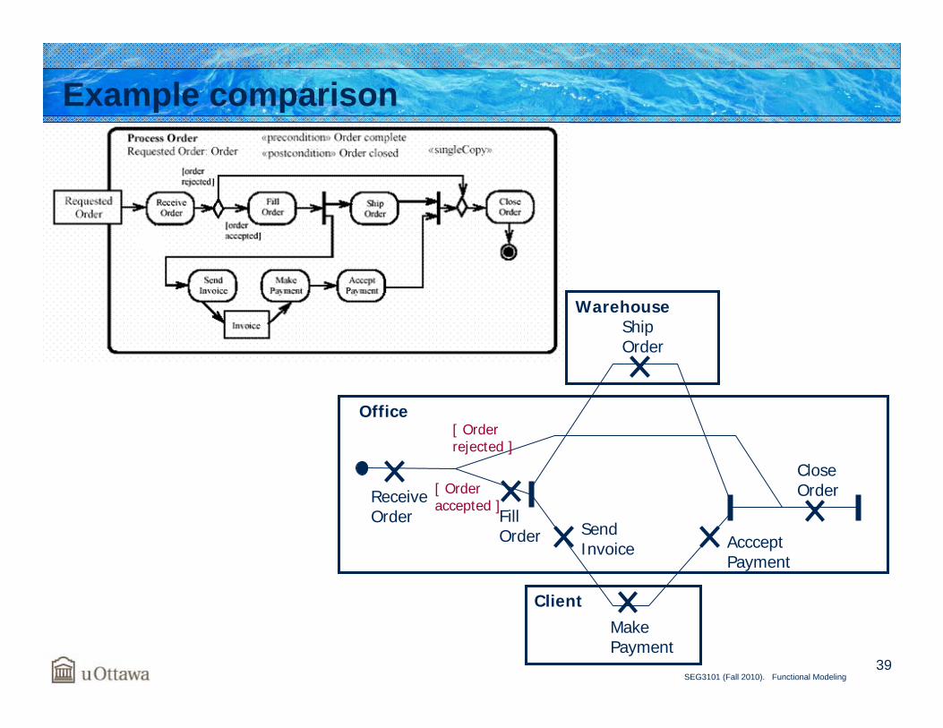
Example comparison
Receive Order Fill
Order SendInvoice
Ship Order
Make Payment
AccceptPayment
CloseOrder
Warehouse
Office
Client
[ Order rejected ]
[ Order accepted ]
40SEG3101 (Fall 2010). Functional Modeling
Unique to UCM• Dynamic stubs with several plug-ins
• Activity diagrams have a single sub-activity diagram per action• Plug-ins can continue in parallel with their parent model
• Sub-activity diagrams must complete before returning to the parent activity diagram
• 2D graphical layout of components• Definitions of scenarios (integrated testing capabilities!)• Integration with GRL in URN
Introduction Class Diagram Activity Diagram Sequence Diagram State Machine Diagram Consistency UML and URN
41SEG3101 (Fall 2010). Functional Modeling
Unique to Activity Diagrams• Data flow modeling• Interruptible regions• Conditions on parallelism (branches of an AND-fork)• Constraints on action pins• Integration with UML
Introduction Class Diagram Activity Diagram Sequence Diagram State Machine Diagram Consistency UML and URN
Model-Based Analysis (for Workflow models)
Sequence Diagram
44SEG3101 (Fall 2010). Functional Modeling
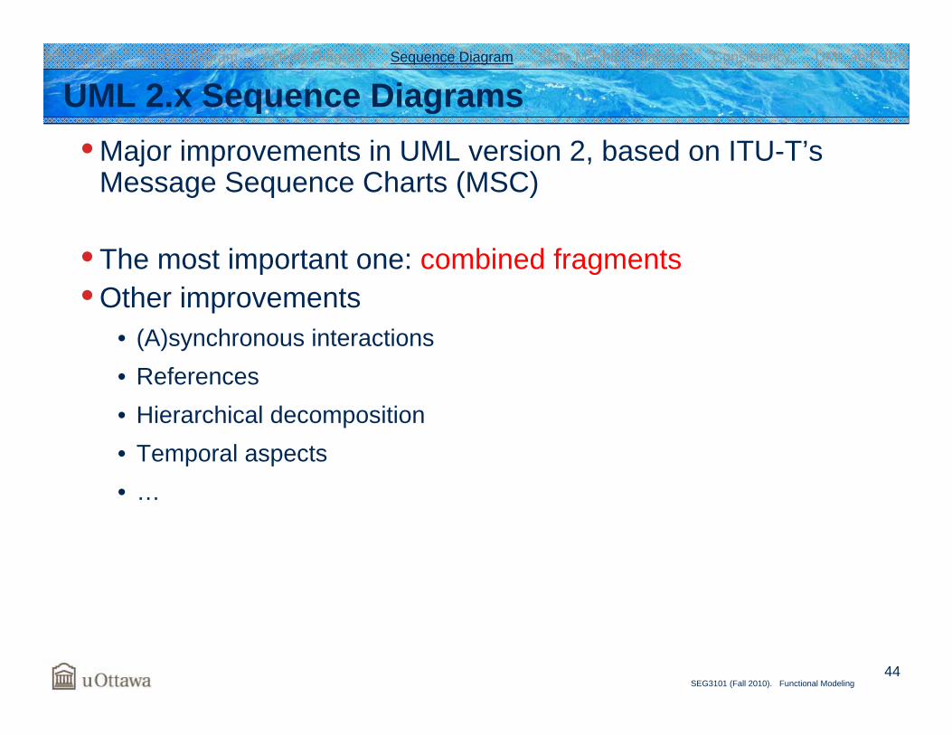
UML 2.x Sequence Diagrams• Major improvements in UML version 2, based on ITU-T’s
Message Sequence Charts (MSC)
• The most important one: combined fragments• Other improvements
• (A)synchronous interactions• References• Hierarchical decomposition• Temporal aspects• …
Introduction Class Diagram Activity Diagram Sequence Diagram State Machine Diagram Consistency UML and URN
45SEG3101 (Fall 2010). Functional Modeling
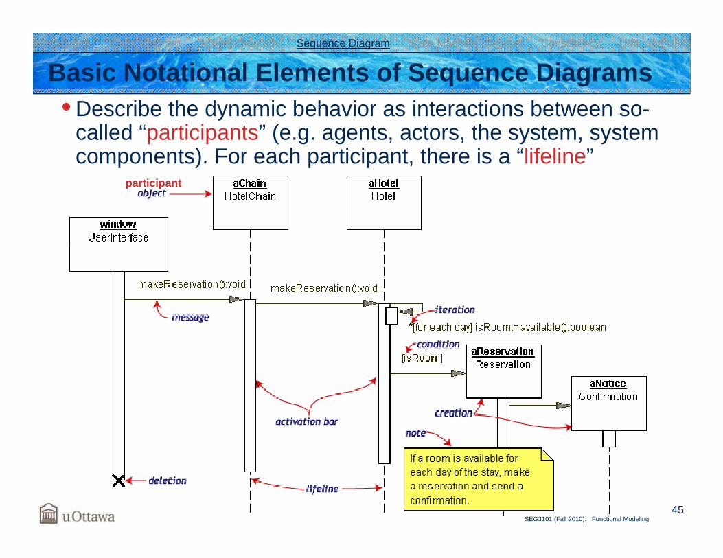
Basic Notational Elements of Sequence Diagrams• Describe the dynamic behavior as interactions between so-
called “participants” (e.g. agents, actors, the system, system components). For each participant, there is a “lifeline”
Introduction Class Diagram Activity Diagram Sequence Diagram State Machine Diagram Consistency UML and URN
participant
46SEG3101 (Fall 2010). Functional Modeling
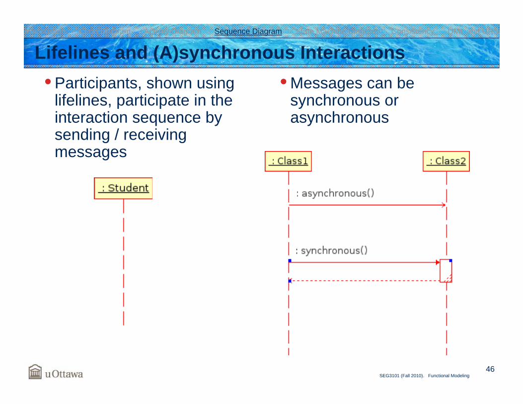
Lifelines and (A)synchronous Interactions• Participants, shown using
lifelines, participate in the interaction sequence by sending / receiving messages
• Messages can be synchronous or asynchronous
Introduction Class Diagram Activity Diagram Sequence Diagram State Machine Diagram Consistency UML and URN
47SEG3101 (Fall 2010). Functional Modeling
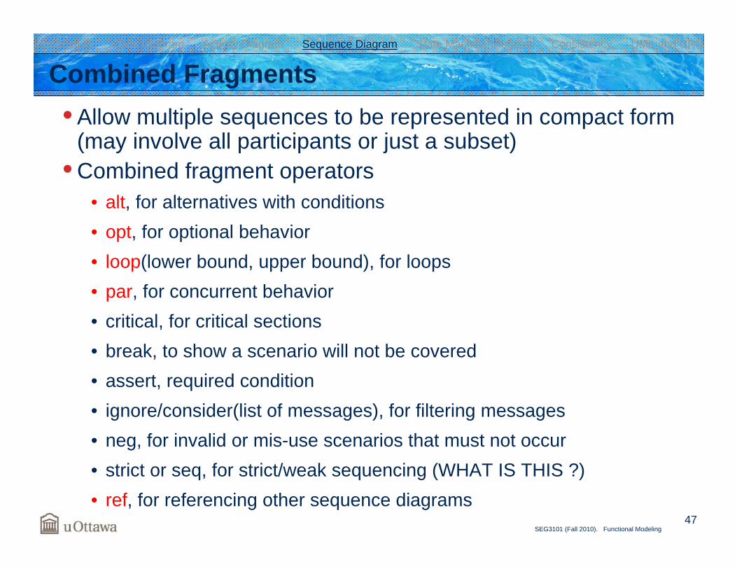
Combined Fragments• Allow multiple sequences to be represented in compact form
(may involve all participants or just a subset)• Combined fragment operators
• alt, for alternatives with conditions• opt, for optional behavior• loop(lower bound, upper bound), for loops• par, for concurrent behavior• critical, for critical sections• break, to show a scenario will not be covered• assert, required condition• ignore/consider(list of messages), for filtering messages• neg, for invalid or mis-use scenarios that must not occur• strict or seq, for strict/weak sequencing (WHAT IS THIS ?)• ref, for referencing other sequence diagrams
Introduction Class Diagram Activity Diagram Sequence Diagram State Machine Diagram Consistency UML and URN
48SEG3101 (Fall 2010). Functional Modeling
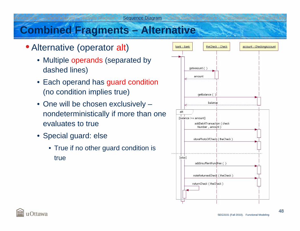
Combined Fragments – Alternative• Alternative (operator alt)
• Multiple operands (separated by dashed lines)
• Each operand has guard condition(no condition implies true)
• One will be chosen exclusively –nondeterministically if more than one evaluates to true
• Special guard: else• True if no other guard condition is
true
Introduction Class Diagram Activity Diagram Sequence Diagram State Machine Diagram Consistency UML and URN
49SEG3101 (Fall 2010). Functional Modeling
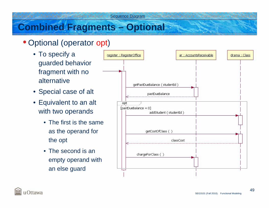
Combined Fragments – Optional• Optional (operator opt)
• To specify a guarded behavior fragment with no alternative
• Special case of alt• Equivalent to an alt
with two operands• The first is the same
as the operand for the opt
• The second is an empty operand withan else guard
Introduction Class Diagram Activity Diagram Sequence Diagram State Machine Diagram Consistency UML and URN
50SEG3101 (Fall 2010). Functional Modeling
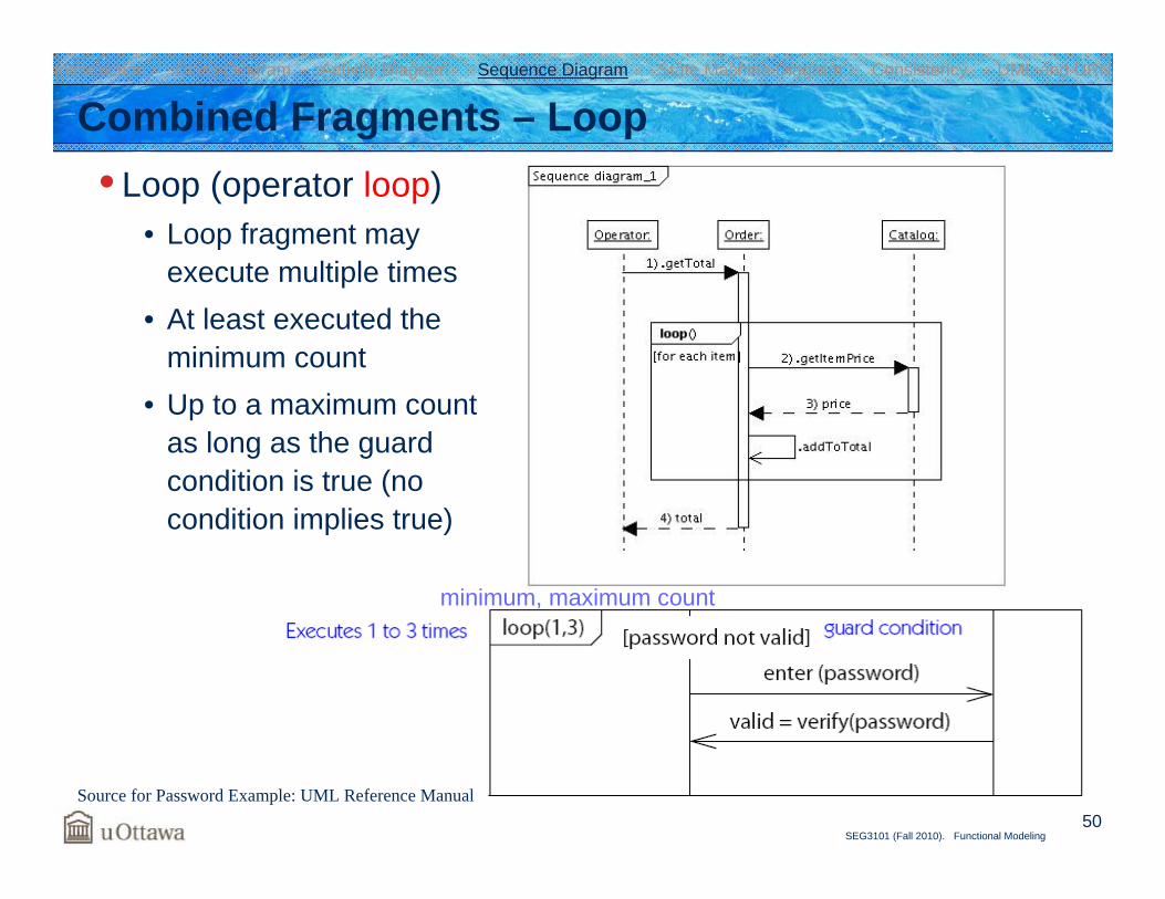
Combined Fragments – Loop• Loop (operator loop)
• Loop fragment may execute multiple times
• At least executed the minimum count
• Up to a maximum count as long as the guard condition is true (no condition implies true)
Source for Password Example: UML Reference Manual
minimum, maximum count
Introduction Class Diagram Activity Diagram Sequence Diagram State Machine Diagram Consistency UML and URN
51SEG3101 (Fall 2010). Functional Modeling
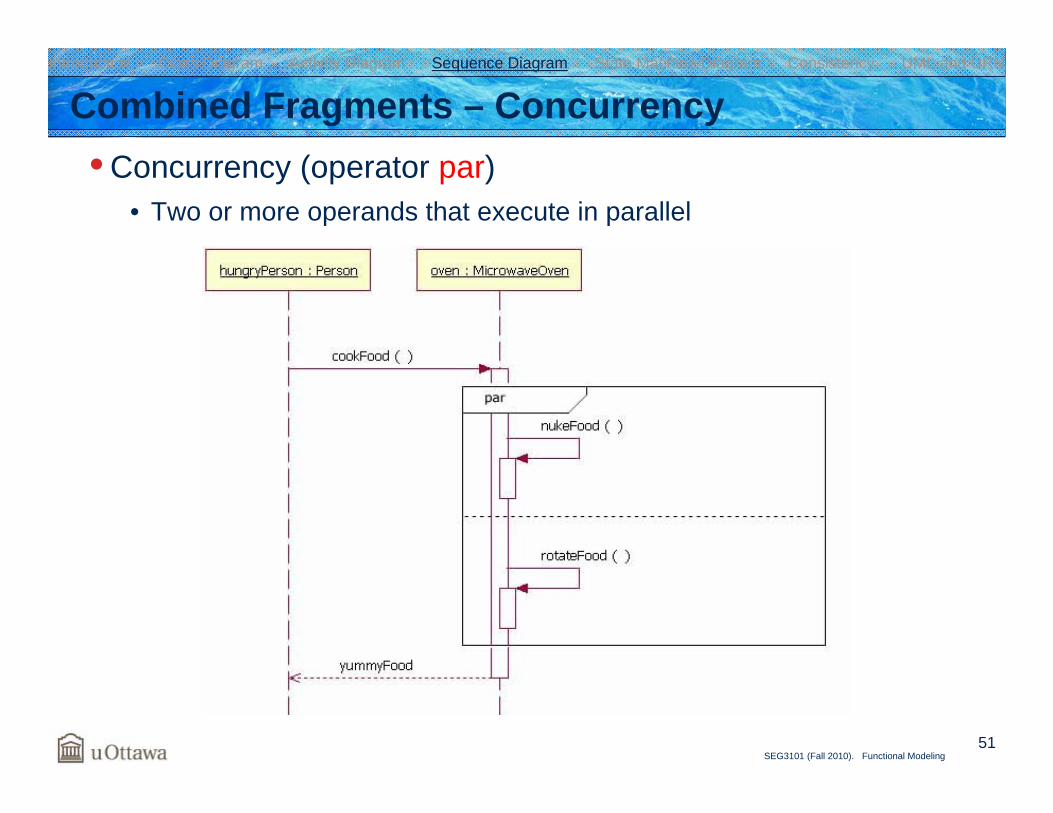
Combined Fragments – Concurrency• Concurrency (operator par)
• Two or more operands that execute in parallel
Introduction Class Diagram Activity Diagram Sequence Diagram State Machine Diagram Consistency UML and URN
52SEG3101 (Fall 2010). Functional Modeling
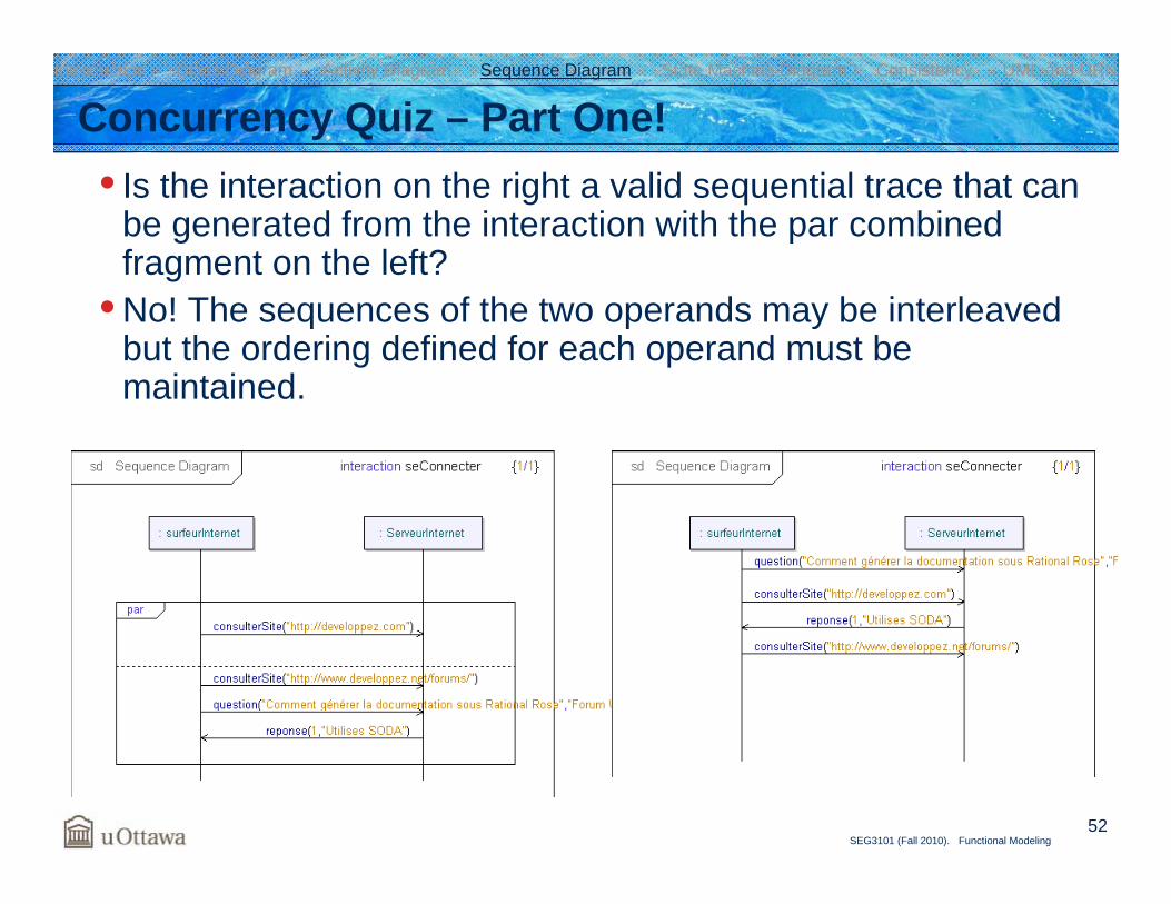
Concurrency Quiz – Part One!• Is the interaction on the right a valid sequential trace that can
be generated from the interaction with the par combined fragment on the left?
• No! The sequences of the two operands may be interleaved but the ordering defined for each operand must be maintained.
Introduction Class Diagram Activity Diagram Sequence Diagram State Machine Diagram Consistency UML and URN
53SEG3101 (Fall 2010). Functional Modeling
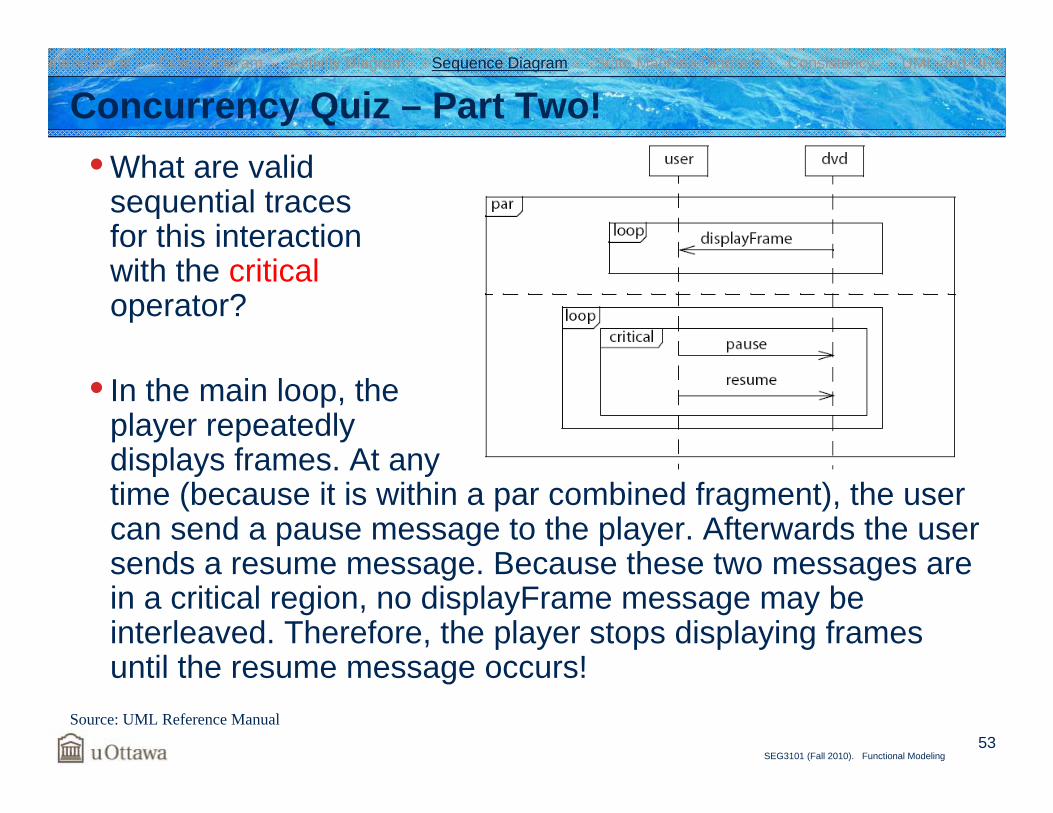
• What are valid sequential traces for this interaction with the criticaloperator?
• In the main loop, the player repeatedly displays frames. At any time (because it is within a par combined fragment), the user can send a pause message to the player. Afterwards the user sends a resume message. Because these two messages are in a critical region, no displayFrame message may be interleaved. Therefore, the player stops displaying frames until the resume message occurs!
Concurrency Quiz – Part Two!
Source: UML Reference Manual
Introduction Class Diagram Activity Diagram Sequence Diagram State Machine Diagram Consistency UML and URN
54SEG3101 (Fall 2010). Functional Modeling
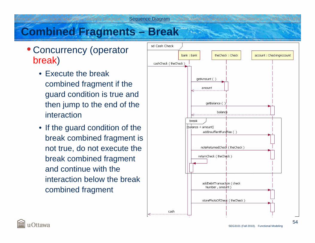
Combined Fragments – Break• Concurrency (operator
break)• Execute the break
combined fragment if the guard condition is true and then jump to the end of the interaction
• If the guard condition of the break combined fragment is not true, do not execute the break combined fragment and continue with the interaction below the break combined fragment
Introduction Class Diagram Activity Diagram Sequence Diagram State Machine Diagram Consistency UML and URN
55SEG3101 (Fall 2010). Functional Modeling
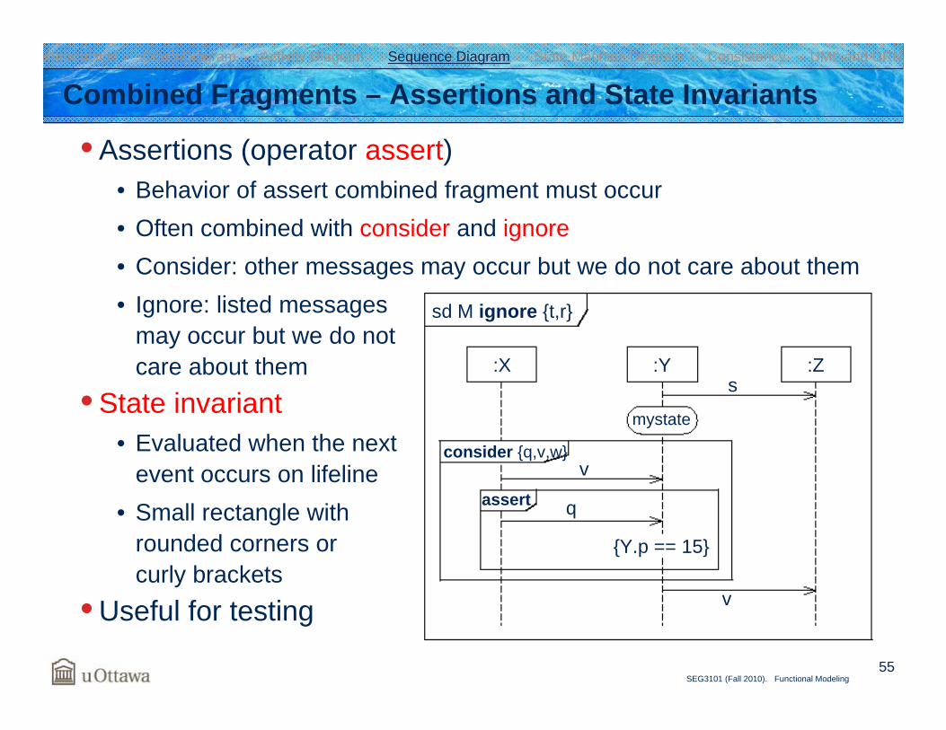
Combined Fragments – Assertions and State Invariants
• Assertions (operator assert)• Behavior of assert combined fragment must occur• Often combined with consider and ignore• Consider: other messages may occur but we do not care about them• Ignore: listed messages
may occur but we do not care about them
• State invariant• Evaluated when the next
event occurs on lifeline• Small rectangle with
rounded corners or curly brackets
• Useful for testing
sd M ignore {t,r}
mystate
:X :Y :Z
consider {q,v,w}
s
v
v
q
{Y.p == 15}
assert
Introduction Class Diagram Activity Diagram Sequence Diagram State Machine Diagram Consistency UML and URN
56SEG3101 (Fall 2010). Functional Modeling
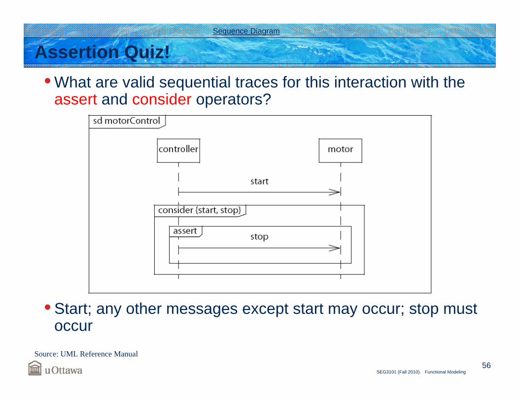
• What are valid sequential traces for this interaction with the assert and consider operators?
• Start; any other messages except start may occur; stop must occur
Assertion Quiz!
Source: UML Reference Manual
Introduction Class Diagram Activity Diagram Sequence Diagram State Machine Diagram Consistency UML and URN
57SEG3101 (Fall 2010). Functional Modeling
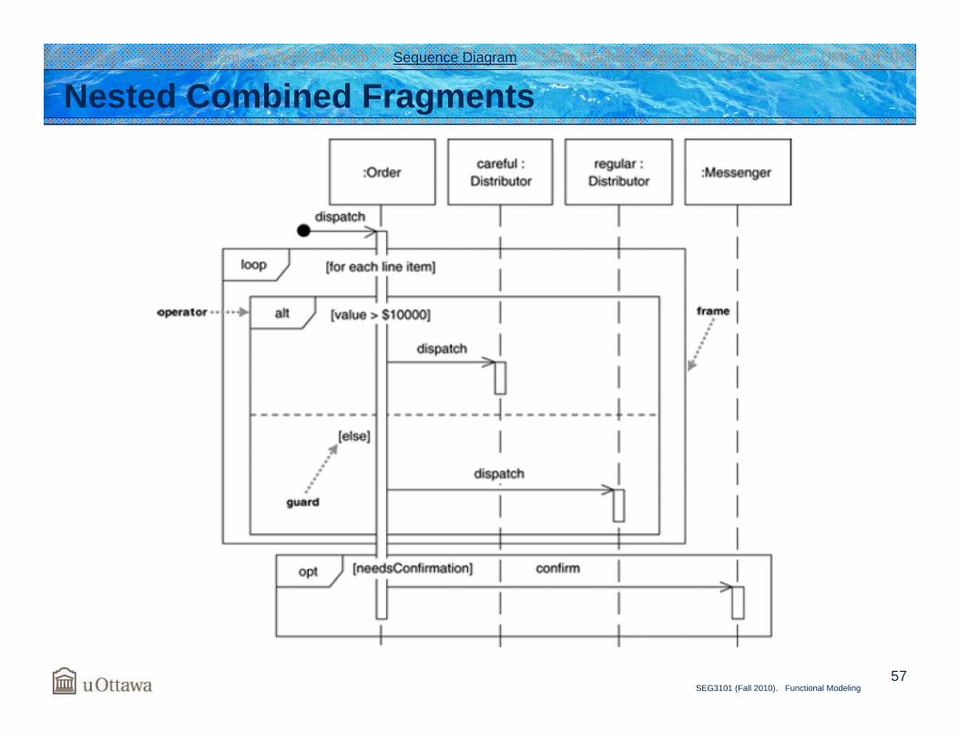
Nested Combined FragmentsIntroduction Class Diagram Activity Diagram Sequence Diagram State Machine Diagram Consistency UML and URN
58SEG3101 (Fall 2010). Functional Modeling
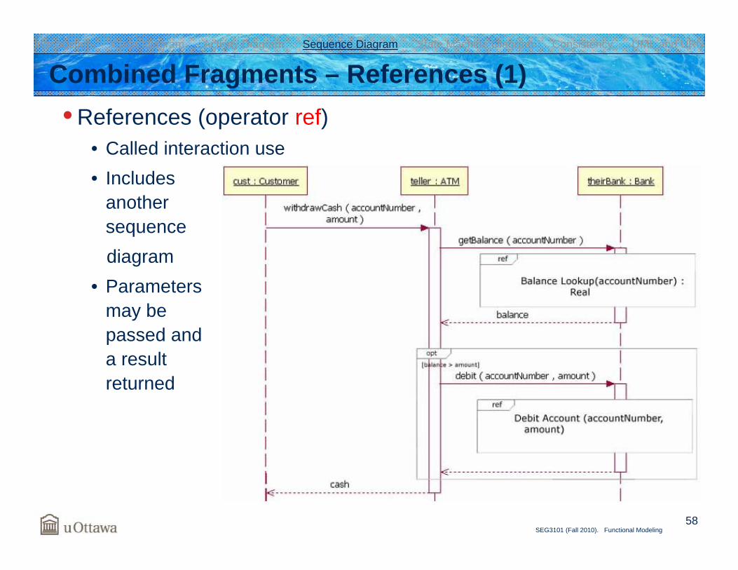
Combined Fragments – References (1)• References (operator ref)
• Called interaction use• Includes
another sequence diagram
• Parameters may be passed and a result returned
Introduction Class Diagram Activity Diagram Sequence Diagram State Machine Diagram Consistency UML and URN
59SEG3101 (Fall 2010). Functional Modeling
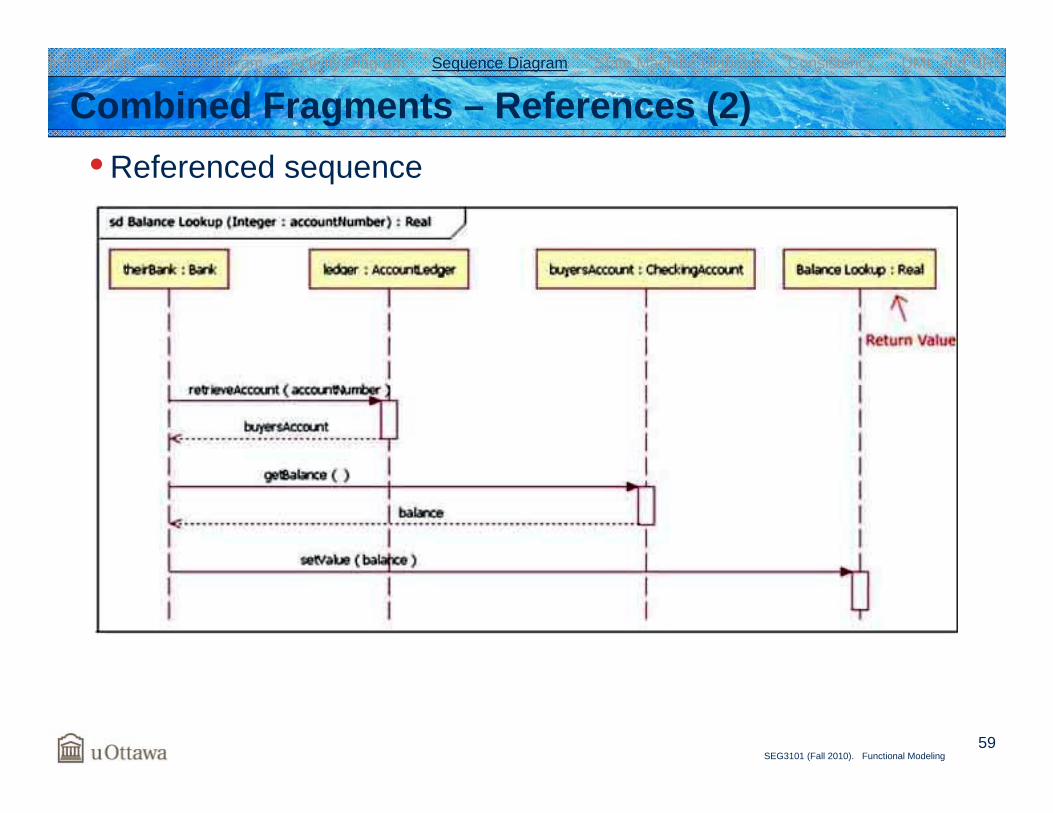
Combined Fragments – References (2)• Referenced sequence
Introduction Class Diagram Activity Diagram Sequence Diagram State Machine Diagram Consistency UML and URN
60SEG3101 (Fall 2010). Functional Modeling
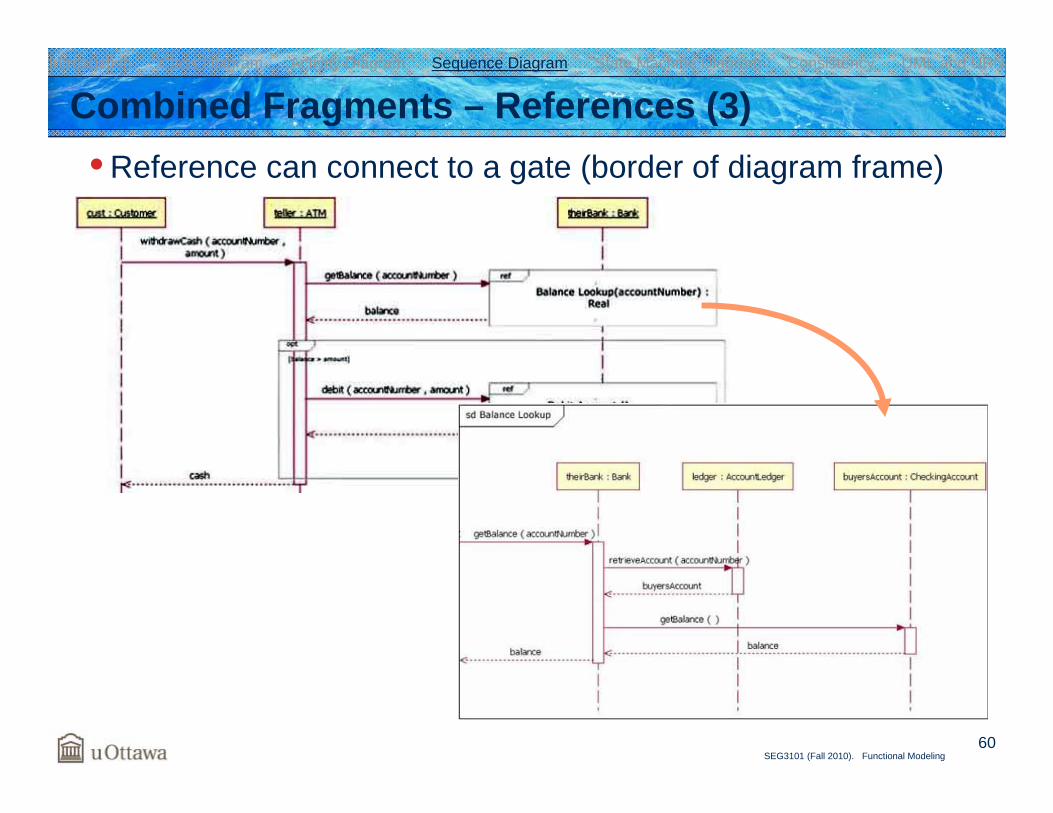
Combined Fragments – References (3)• Reference can connect to a gate (border of diagram frame)
Introduction Class Diagram Activity Diagram Sequence Diagram State Machine Diagram Consistency UML and URN
61SEG3101 (Fall 2010). Functional Modeling
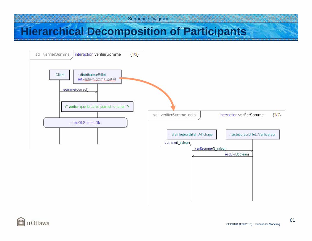
Hierarchical Decomposition of ParticipantsIntroduction Class Diagram Activity Diagram Sequence Diagram State Machine Diagram Consistency UML and URN
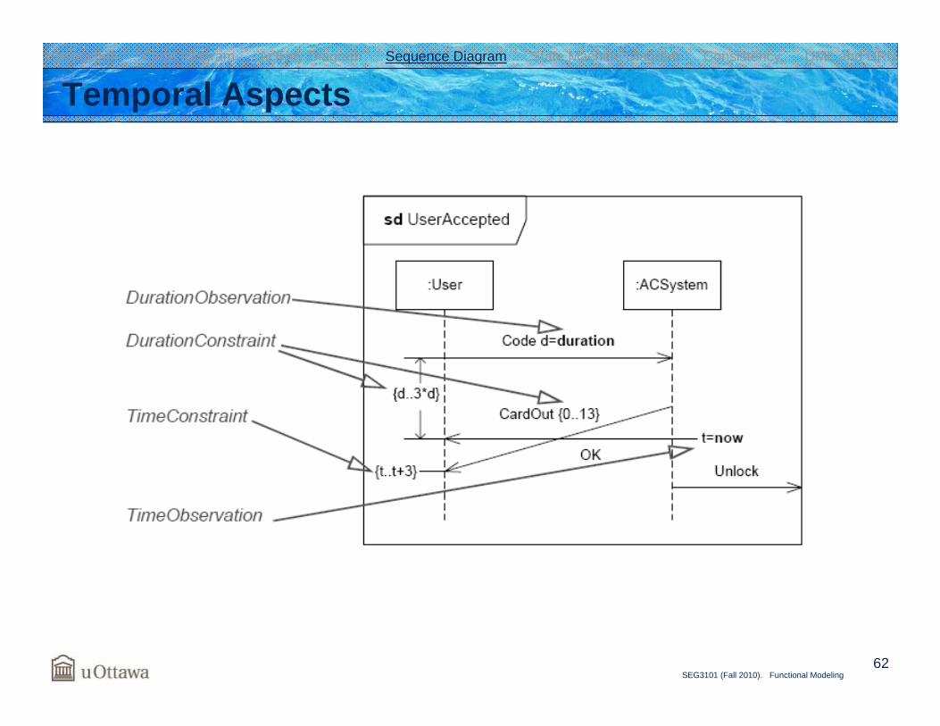
62SEG3101 (Fall 2010). Functional Modeling
Temporal AspectsIntroduction Class Diagram Activity Diagram Sequence Diagram State Machine Diagram Consistency UML and URN
63SEG3101 (Fall 2010). Functional Modeling
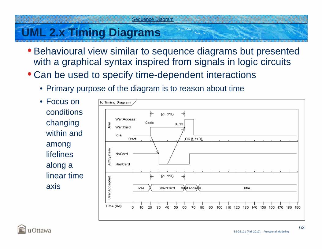
UML 2.x Timing Diagrams • Behavioural view similar to sequence diagrams but presented
with a graphical syntax inspired from signals in logic circuits• Can be used to specify time-dependent interactions
• Primary purpose of the diagram is to reason about time• Focus on
conditions changing within and among lifelines along a linear time axis
Introduction Class Diagram Activity Diagram Sequence Diagram State Machine Diagram Consistency UML and URN
64SEG3101 (Fall 2010). Functional Modeling
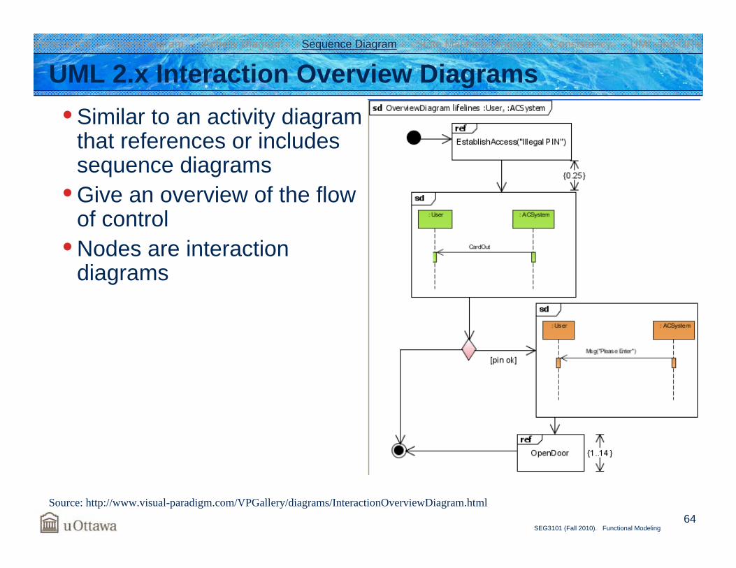
UML 2.x Interaction Overview Diagrams• Similar to an activity diagram
that references or includes sequence diagrams
• Give an overview of the flow of control
• Nodes are interaction diagrams
Source: http://www.visual-paradigm.com/VPGallery/diagrams/InteractionOverviewDiagram.html
Introduction Class Diagram Activity Diagram Sequence Diagram State Machine Diagram Consistency UML and URN

State Machine Diagram
66SEG3101 (Fall 2010). Functional Modeling
UML 2.x State Machine Diagrams• Model discrete behavior (finite state-transition systems)
• System• Component• Class• Protocol
• Several formal definitions as well as textual and graphical syntax of state machines exist
• We focus on the state machines of UML 2.x• Several techniques and tools exist for defining, analyzing,
combining, and transforming (e.g., to code) state machines
Introduction Class Diagram Activity Diagram Sequence Diagram State Machine Diagram Consistency UML and URN
67SEG3101 (Fall 2010). Functional Modeling
ONONON ONONON
OFFOFFOFFOFFOFFOFF
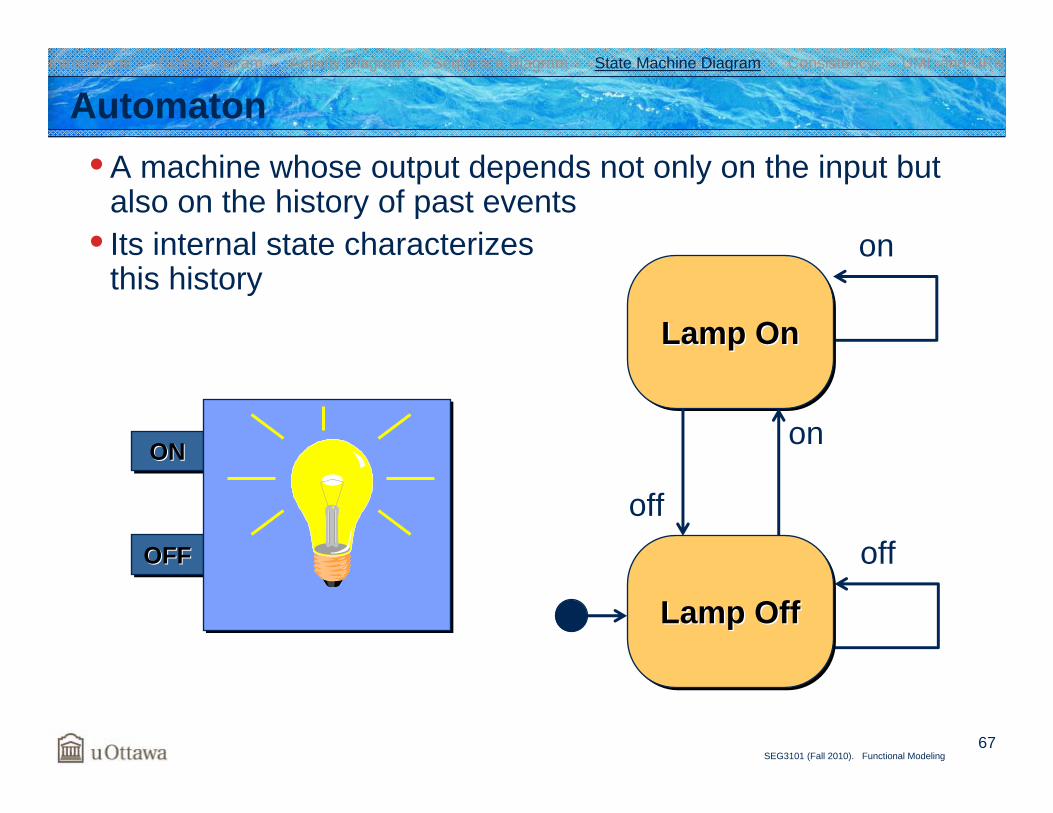
Automaton• A machine whose output depends not only on the input but
also on the history of past events• Its internal state characterizes
this history
Introduction Class Diagram Activity Diagram Sequence Diagram State Machine Diagram Consistency UML and URN
off
on
Lamp OnLamp OnLamp On
Lamp OffLamp OffLamp Off
off
onONONON
OFFOFFOFF
68SEG3101 (Fall 2010). Functional Modeling
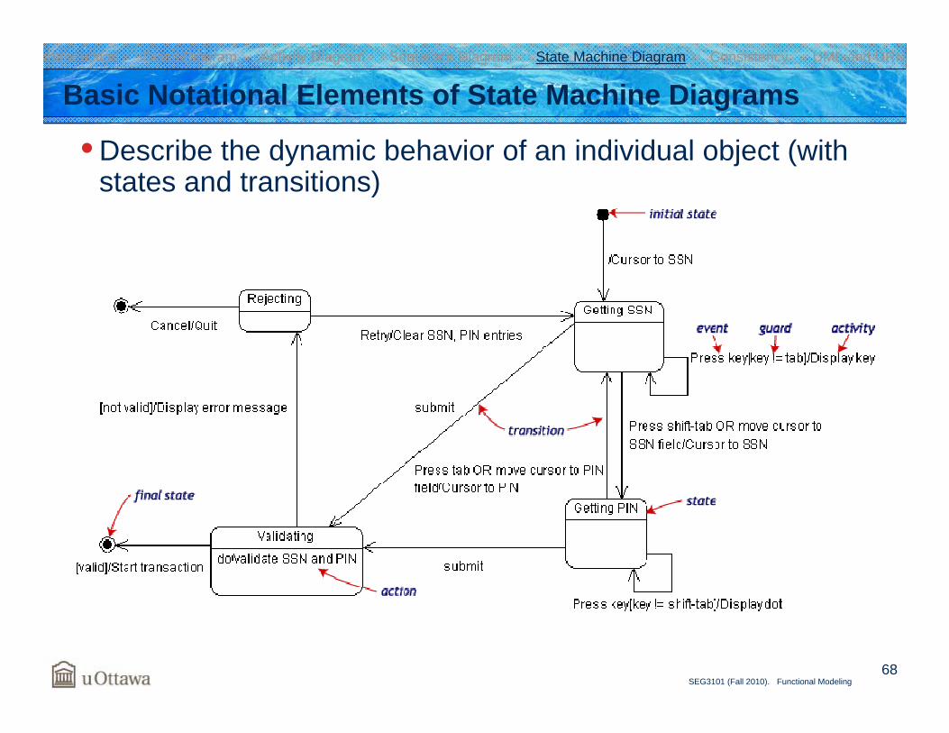
• Describe the dynamic behavior of an individual object (with states and transitions)
Basic Notational Elements of State Machine DiagramsIntroduction Class Diagram Activity Diagram Sequence Diagram State Machine Diagram Consistency UML and URN
69SEG3101 (Fall 2010). Functional Modeling
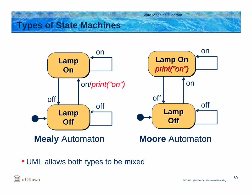
Types of State Machines
• UML allows both types to be mixed
on
off
Lamp Onprint(”on”)Lamp OnLamp Onprint(print(””onon””))
Lamp Off
Lamp Lamp OffOff
off
on
Moore Automaton
on
off
Lamp On
Lamp Lamp OnOn
Lamp Off
Lamp Lamp OffOff
off
on/print(print(””onon””))
Mealy Automaton
Introduction Class Diagram Activity Diagram Sequence Diagram State Machine Diagram Consistency UML and URN
70SEG3101 (Fall 2010). Functional Modeling
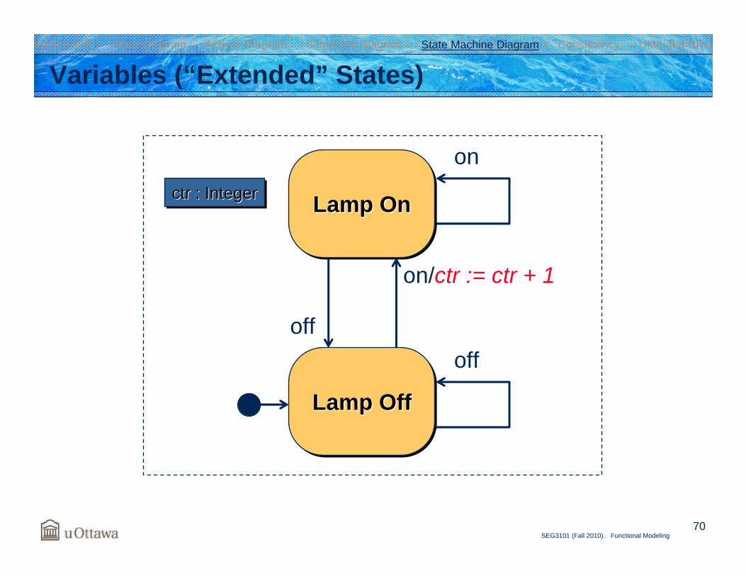
Variables (“Extended” States)
off
on
Lamp OnLamp OnLamp On
Lamp OffLamp OffLamp Off
off
on/ctr := ctr + 1
ctr : Integerctrctr : Integer: Integer
Introduction Class Diagram Activity Diagram Sequence Diagram State Machine Diagram Consistency UML and URN
71SEG3101 (Fall 2010). Functional Modeling
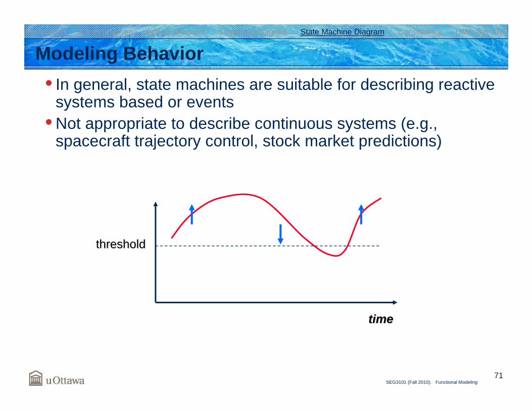
Modeling Behavior• In general, state machines are suitable for describing reactive
systems based or events• Not appropriate to describe continuous systems (e.g.,
spacecraft trajectory control, stock market predictions)
timetime
thresholdthreshold
Introduction Class Diagram Activity Diagram Sequence Diagram State Machine Diagram Consistency UML and URN
72SEG3101 (Fall 2010). Functional Modeling
top
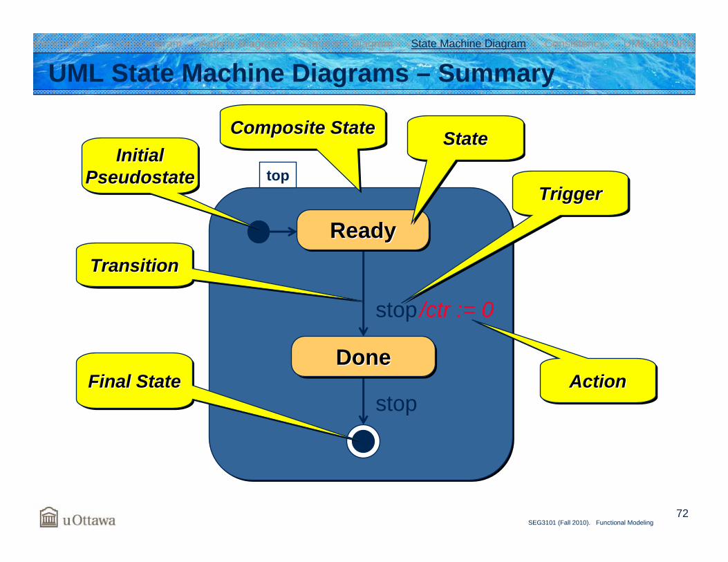
UML State Machine Diagrams – Summary
ReadyReadyReady
stop
/ctr := 0stop
StateStateState
TriggerTriggerTrigger
ActionActionAction
InitialPseudostate
InitialInitialPseudostatePseudostate
TransitionTransitionTransition
Final StateFinal StateFinal StateDoneDoneDone
Composite StateComposite StateComposite State
Introduction Class Diagram Activity Diagram Sequence Diagram State Machine Diagram Consistency UML and URN
73SEG3101 (Fall 2010). Functional Modeling
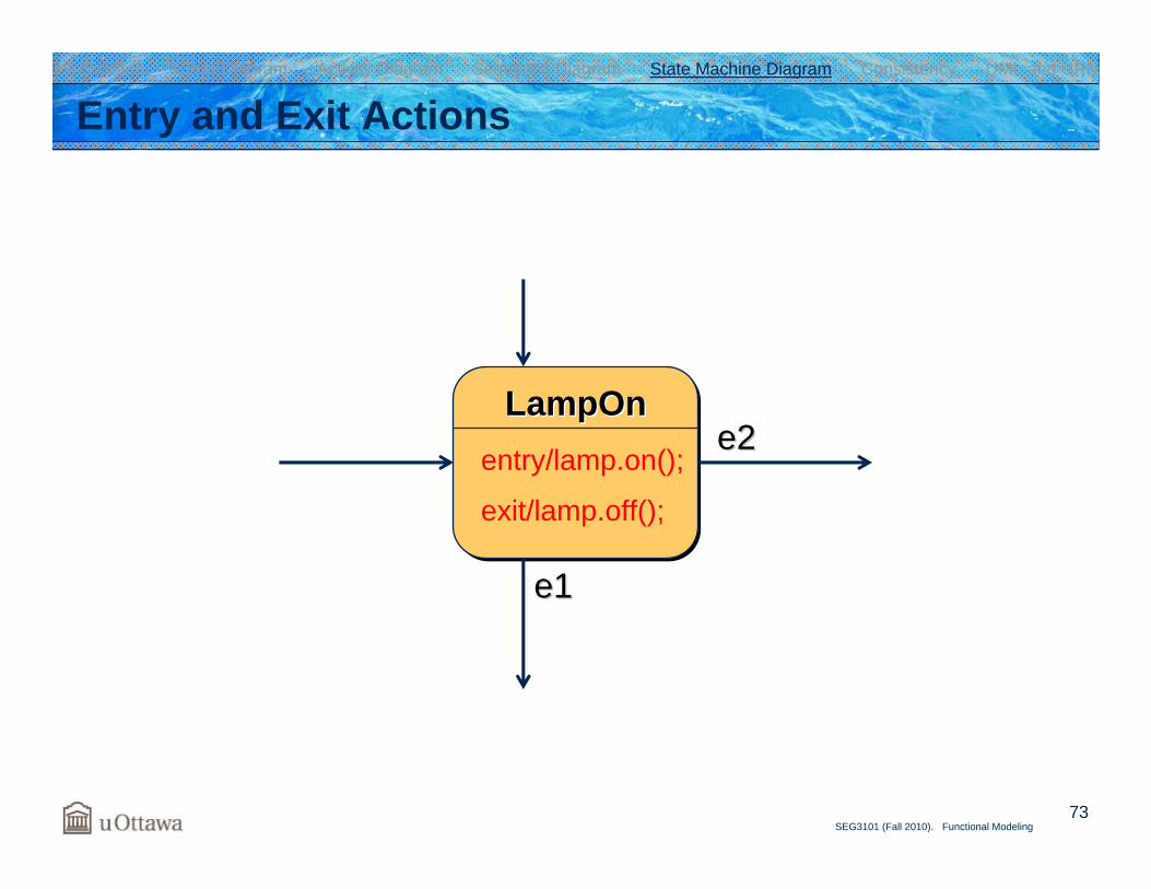
Entry and Exit Actions
LampOnLampOnLampOnentry/lamp.on();
exit/lamp.off();
e1e1
e2e2
Introduction Class Diagram Activity Diagram Sequence Diagram State Machine Diagram Consistency UML and URN
74SEG3101 (Fall 2010). Functional Modeling
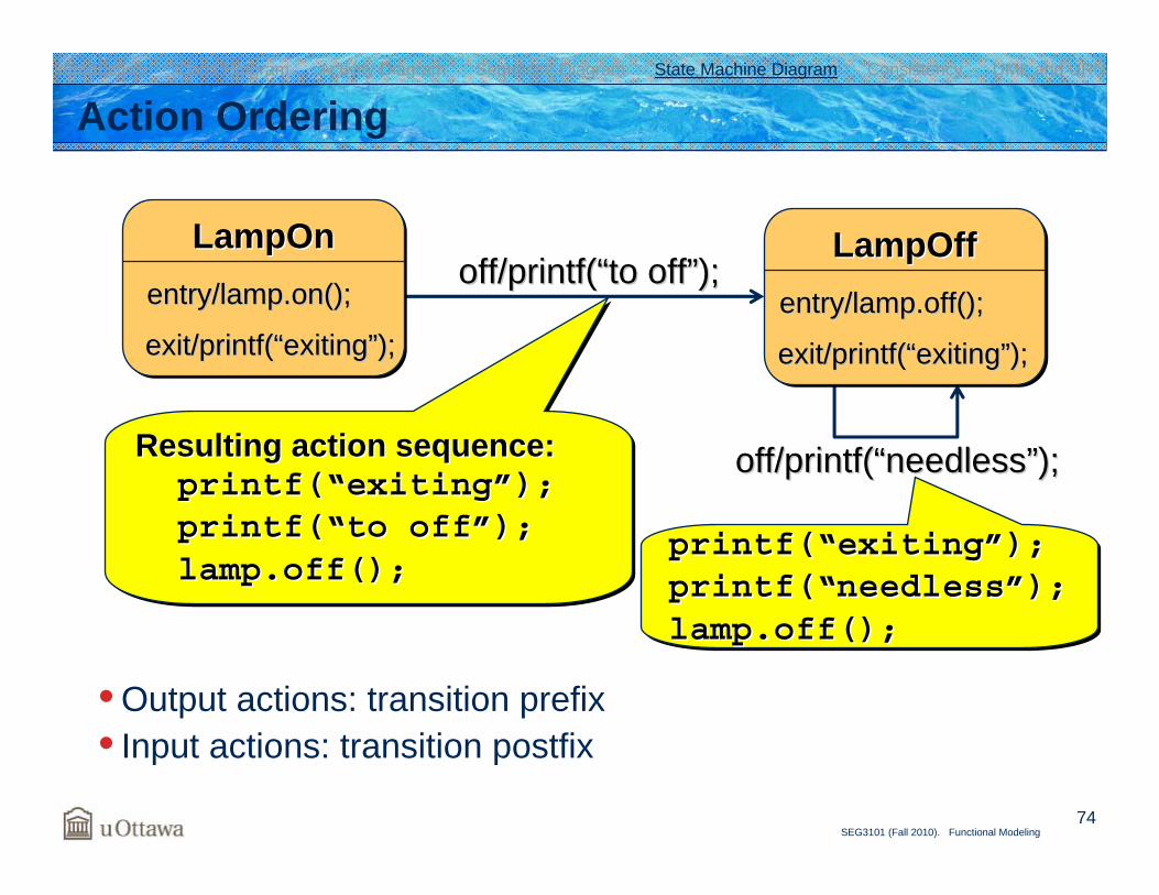
Resulting action sequence:printf(“exiting”);printf(“to off”);lamp.off();
Resulting action sequence:Resulting action sequence:printf(printf(““exitingexiting””););printf(printf(““toto offoff””););lamp.offlamp.off();();
Action Ordering
• Output actions: transition prefix• Input actions: transition postfix
printf(“exiting”);printf(“needless”);lamp.off();
printf(printf(““exitingexiting””););printf(printf(““needlessneedless””););lamp.off();lamp.off();
off/off/printf(printf(““needlessneedless””););
off/off/printf(printf(““toto offoff””););LampOffLampOffLampOff
entry/lamp.off();entry/lamp.off();
exit/exit/printf(printf(““exitingexiting””););
LampOnLampOnLampOnentry/lamp.on();entry/lamp.on();
exit/exit/printf(printf(““exitingexiting””););
Introduction Class Diagram Activity Diagram Sequence Diagram State Machine Diagram Consistency UML and URN
75SEG3101 (Fall 2010). Functional Modeling
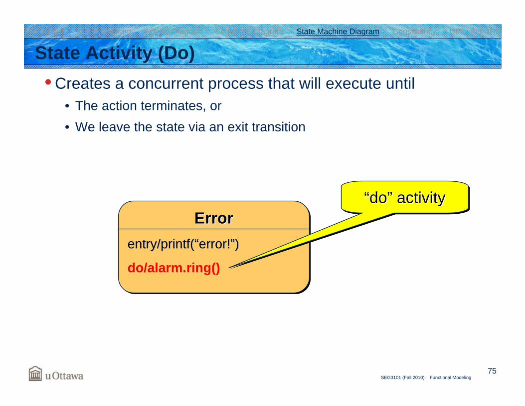
ErrorErrorErrorentry/entry/printf(printf(““errorerror!!””))
State Activity (Do)• Creates a concurrent process that will execute until
• The action terminates, or• We leave the state via an exit transition
do/alarm.ring()
“do” activity““dodo”” activityactivity
Introduction Class Diagram Activity Diagram Sequence Diagram State Machine Diagram Consistency UML and URN
76SEG3101 (Fall 2010). Functional Modeling
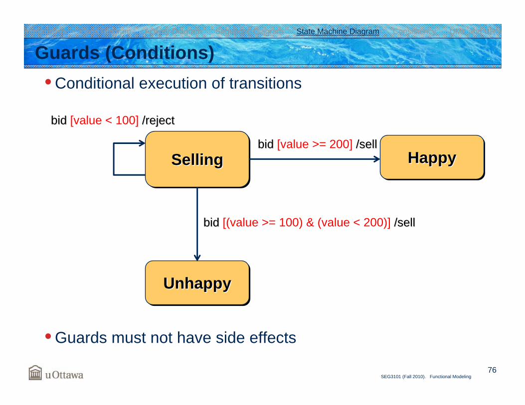
Guards (Conditions)• Conditional execution of transitions
• Guards must not have side effects
SellingSellingSelling
UnhappyUnhappyUnhappy
HappyHappyHappy
bid bid [(value >= 100) & (value < 200)] /sell/sell
bid bid [value >= 200] /sell/sell
bid bid [value < 100] /reject/reject
Introduction Class Diagram Activity Diagram Sequence Diagram State Machine Diagram Consistency UML and URN
77SEG3101 (Fall 2010). Functional Modeling
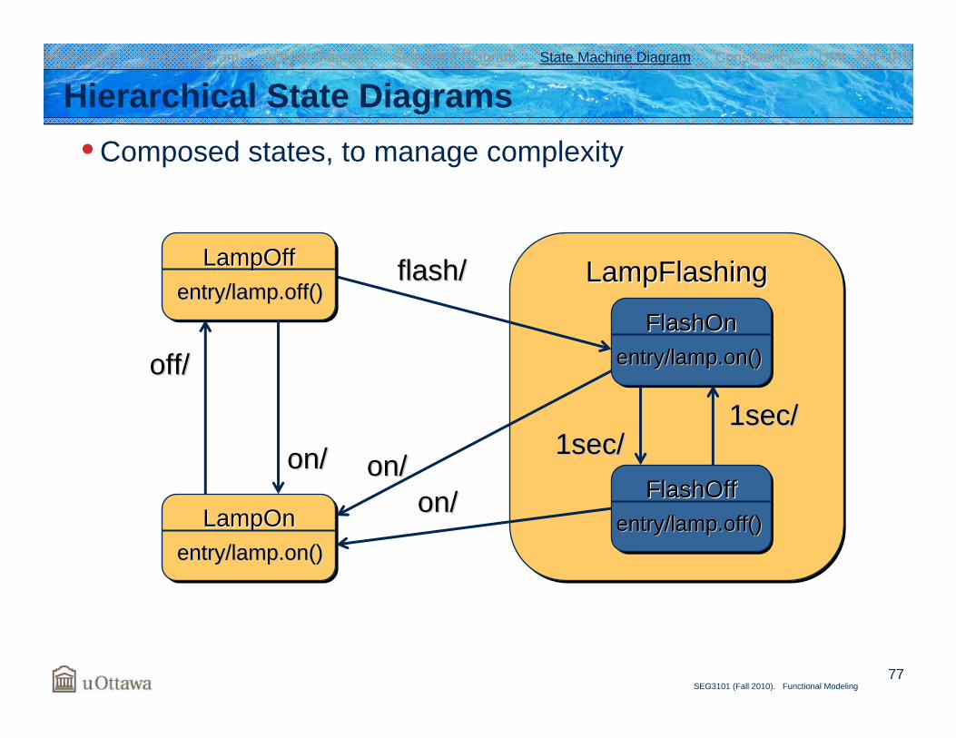
Hierarchical State Diagrams• Composed states, to manage complexity
LampFlashingLampFlashingLampFlashingflash/flash/
1sec/1sec/1sec/1sec/
FlashOffFlashOffFlashOffentry/lamp.off()entry/lamp.off()
FlashOnFlashOnFlashOnentry/lamp.on()entry/lamp.on()off/off/
LampOffLampOffLampOffentry/lamp.off()entry/lamp.off()
LampOnLampOnLampOnentry/lamp.on()entry/lamp.on()
on/on/on/on/
on/on/
Introduction Class Diagram Activity Diagram Sequence Diagram State Machine Diagram Consistency UML and URN
78SEG3101 (Fall 2010). Functional Modeling
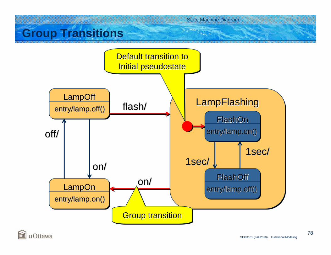
LampFlashingLampFlashingLampFlashing
1sec/1sec/1sec/1sec/
FlashOffFlashOffFlashOffentry/lamp.off()entry/lamp.off()
FlashOnFlashOnFlashOnentry/lamp.on()entry/lamp.on()off/off/
LampOffLampOffLampOffentry/lamp.off()entry/lamp.off()
LampOnLampOnLampOnentry/lamp.on()entry/lamp.on()
on/on/
Group Transitions
flash/flash/
on/on/
Default transition toInitial pseudostate
Default transition toDefault transition toInitial Initial pseudostatepseudostate
Group transitionGroup transitionGroup transition
Introduction Class Diagram Activity Diagram Sequence Diagram State Machine Diagram Consistency UML and URN
79SEG3101 (Fall 2010). Functional Modeling
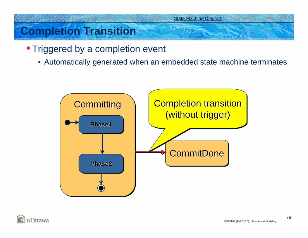
Completion Transition• Triggered by a completion event
• Automatically generated when an embedded state machine terminates
CommittingCommittingCommitting
Phase1Phase1Phase1
Phase2Phase2Phase2CommitDoneCommitDoneCommitDone
Completion transition(without trigger)
Completion transitionCompletion transition(without trigger)(without trigger)
Introduction Class Diagram Activity Diagram Sequence Diagram State Machine Diagram Consistency UML and URN
80SEG3101 (Fall 2010). Functional Modeling
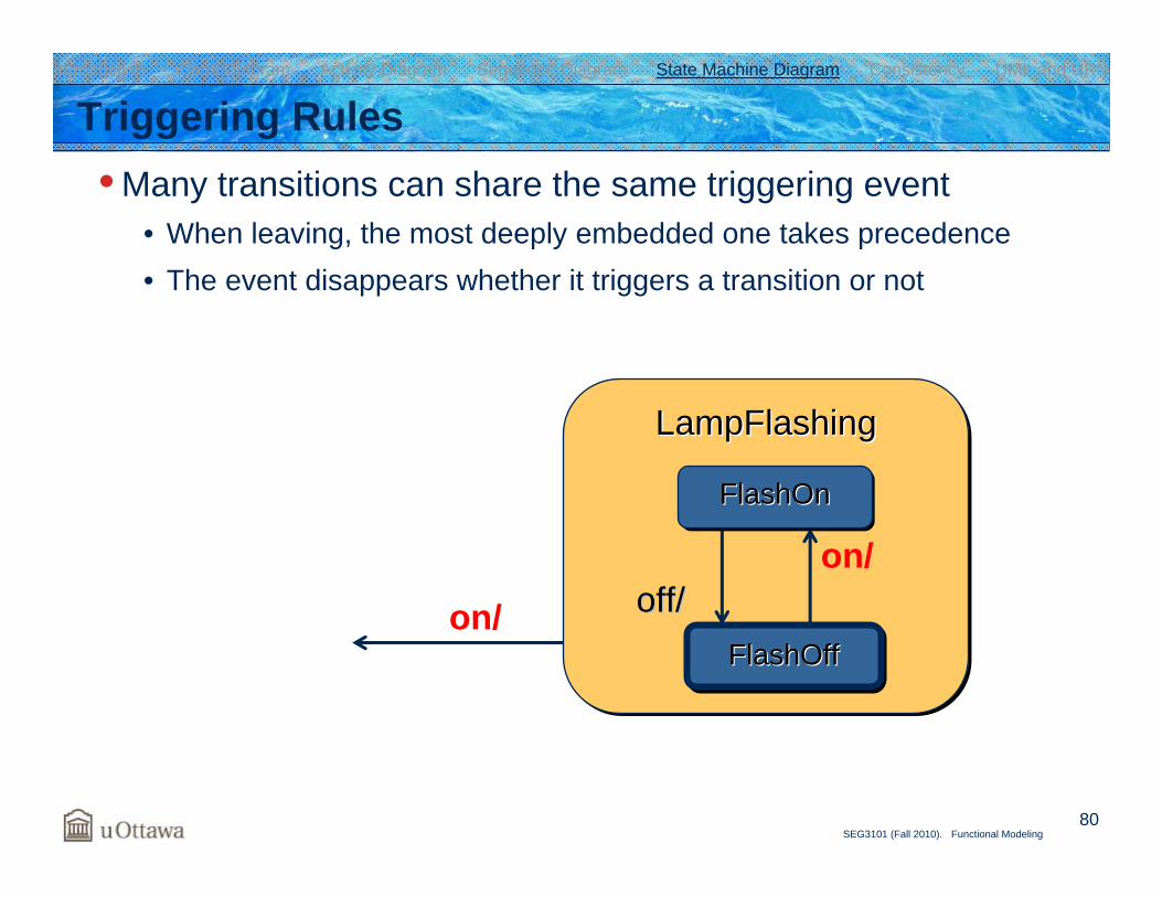
LampFlashingLampFlashingLampFlashing
off/off/FlashOffFlashOffFlashOff
FlashOnFlashOnFlashOn
Triggering Rules• Many transitions can share the same triggering event
• When leaving, the most deeply embedded one takes precedence• The event disappears whether it triggers a transition or not
on/
on/
Introduction Class Diagram Activity Diagram Sequence Diagram State Machine Diagram Consistency UML and URN
81SEG3101 (Fall 2010). Functional Modeling
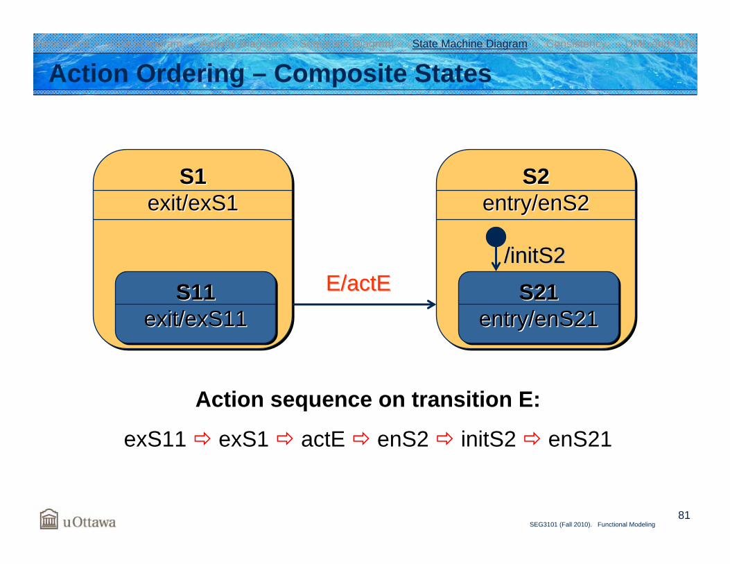
Action Ordering – Composite States
S1exit/exS1
S1S1exit/exS1exit/exS1
S11exit/exS11
S11S11exit/exS11exit/exS11
S2entry/enS2
S2S2entry/enS2entry/enS2
S21entry/enS21
S21S21entry/enS21entry/enS21
/initS2/initS2E/E/actEactE
Action sequence on transition E:
exS11 exS1 actE enS2 initS2 enS21
Introduction Class Diagram Activity Diagram Sequence Diagram State Machine Diagram Consistency UML and URN
82SEG3101 (Fall 2010). Functional Modeling
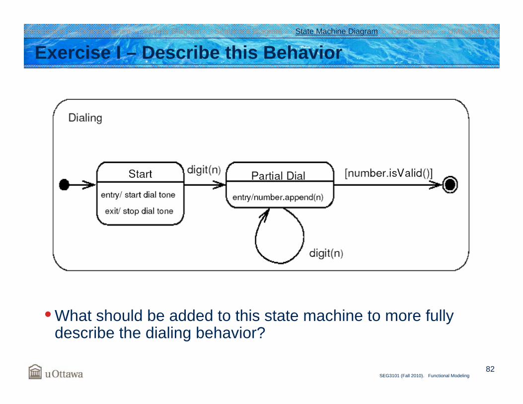
Exercise I – Describe this Behavior
• What should be added to this state machine to more fully describe the dialing behavior?
Introduction Class Diagram Activity Diagram Sequence Diagram State Machine Diagram Consistency UML and URN
83SEG3101 (Fall 2010). Functional Modeling
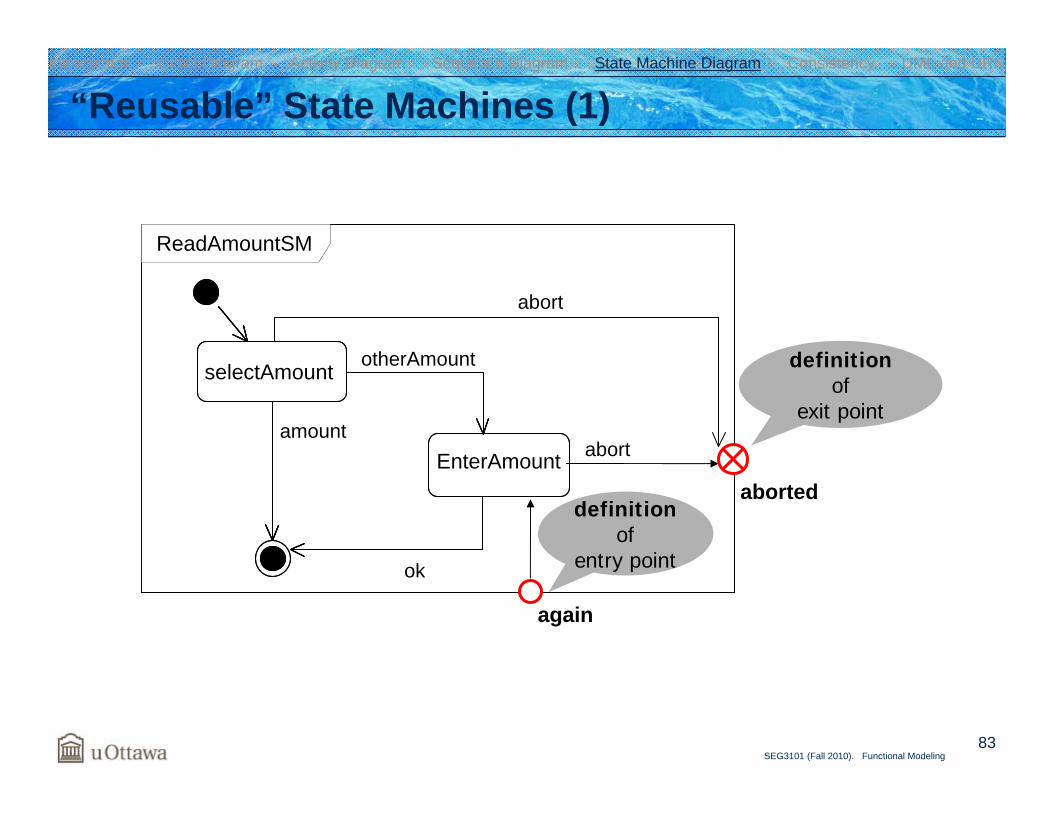
“Reusable” State Machines (1)
definitionof
exit point
ReadAmountSM
selectAmount
EnterAmount
ok
abort
aborted
amount
otherAmount
abort
again
definitionof
entry point
Introduction Class Diagram Activity Diagram Sequence Diagram State Machine Diagram Consistency UML and URN
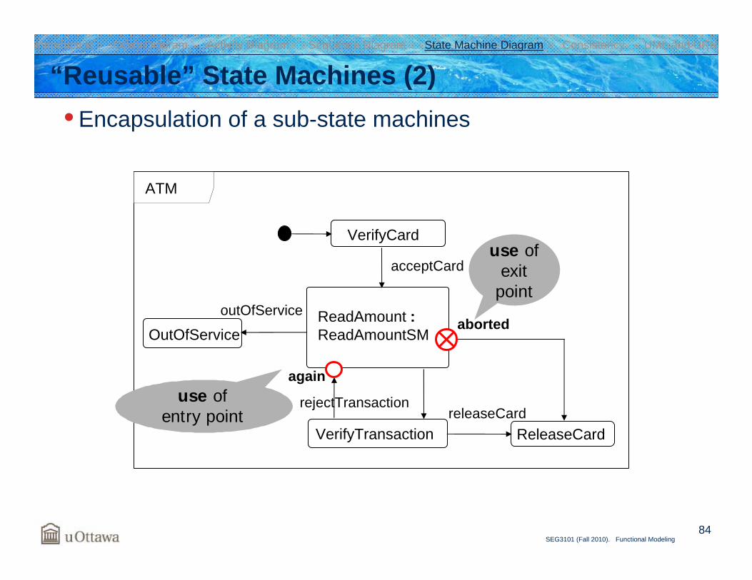
84SEG3101 (Fall 2010). Functional Modeling
“Reusable” State Machines (2)• Encapsulation of a sub-state machines
VerifyCard
OutOfService
acceptCard
ReleaseCardVerifyTransaction
outOfService
releaseCard
ReadAmount :ReadAmountSM
aborted
use of exit
point
use of entry point
rejectTransaction
again
ATM
Introduction Class Diagram Activity Diagram Sequence Diagram State Machine Diagram Consistency UML and URN
85SEG3101 (Fall 2010). Functional Modeling
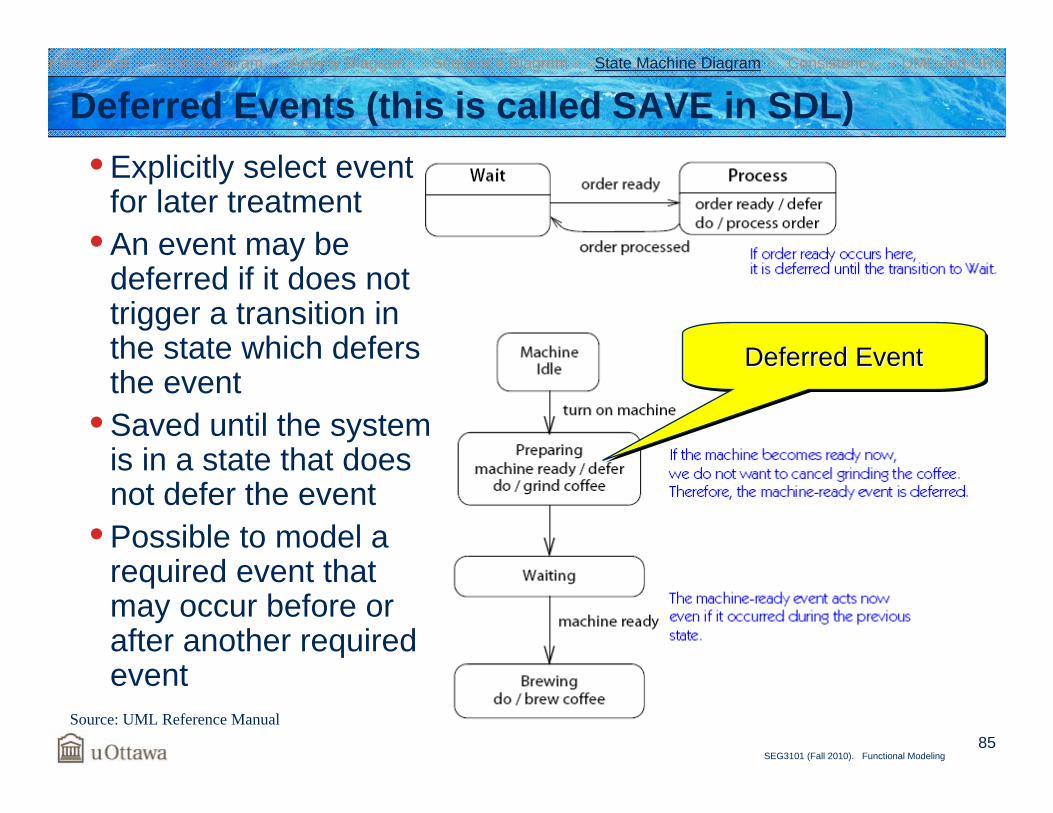
Deferred Events (this is called SAVE in SDL)• Explicitly select event
for later treatment• An event may be
deferred if it does not trigger a transition in the state which defers the event
• Saved until the system is in a state that does not defer the event
• Possible to model a required event that may occur before or after another required event
Introduction Class Diagram Activity Diagram Sequence Diagram State Machine Diagram Consistency UML and URN
Source: UML Reference Manual
Deferred EventDeferred EventDeferred Event
86SEG3101 (Fall 2010). Functional Modeling
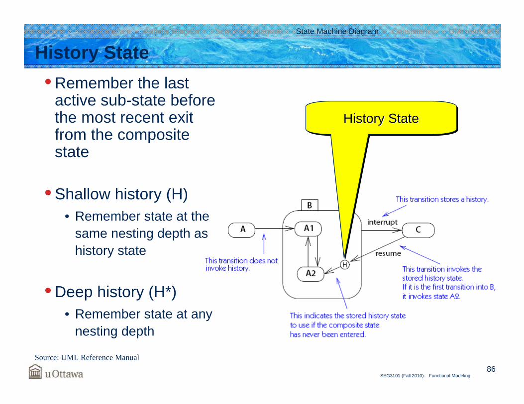
History State• Remember the last
active sub-state before the most recent exit from the composite state
• Shallow history (H)• Remember state at the
same nesting depth as history state
• Deep history (H*)• Remember state at any
nesting depth
Introduction Class Diagram Activity Diagram Sequence Diagram State Machine Diagram Consistency UML and URN
Source: UML Reference Manual
History StateHistory StateHistory State
87SEG3101 (Fall 2010). Functional Modeling
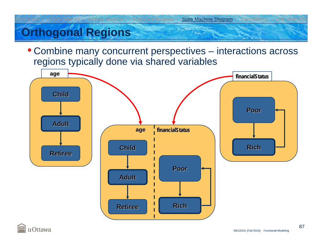
Orthogonal Regions• Combine many concurrent perspectives – interactions across
regions typically done via shared variables
ChildChild
AdultAdult
RetireeRetiree
ageage
PoorPoor
RichRich
financialStatusfinancialStatus
PoorPoor
RichRich
financialStatusfinancialStatus
ChildChild
AdultAdult
RetireeRetiree
ageage
Introduction Class Diagram Activity Diagram Sequence Diagram State Machine Diagram Consistency UML and URN
88SEG3101 (Fall 2010). Functional Modeling
OutlawOutlawOutlaw
LawAbidingLawAbidingLawAbiding PoorPoorPoor
RichRichRich
financialStatusfinancialStatuslegalStatuslegalStatus
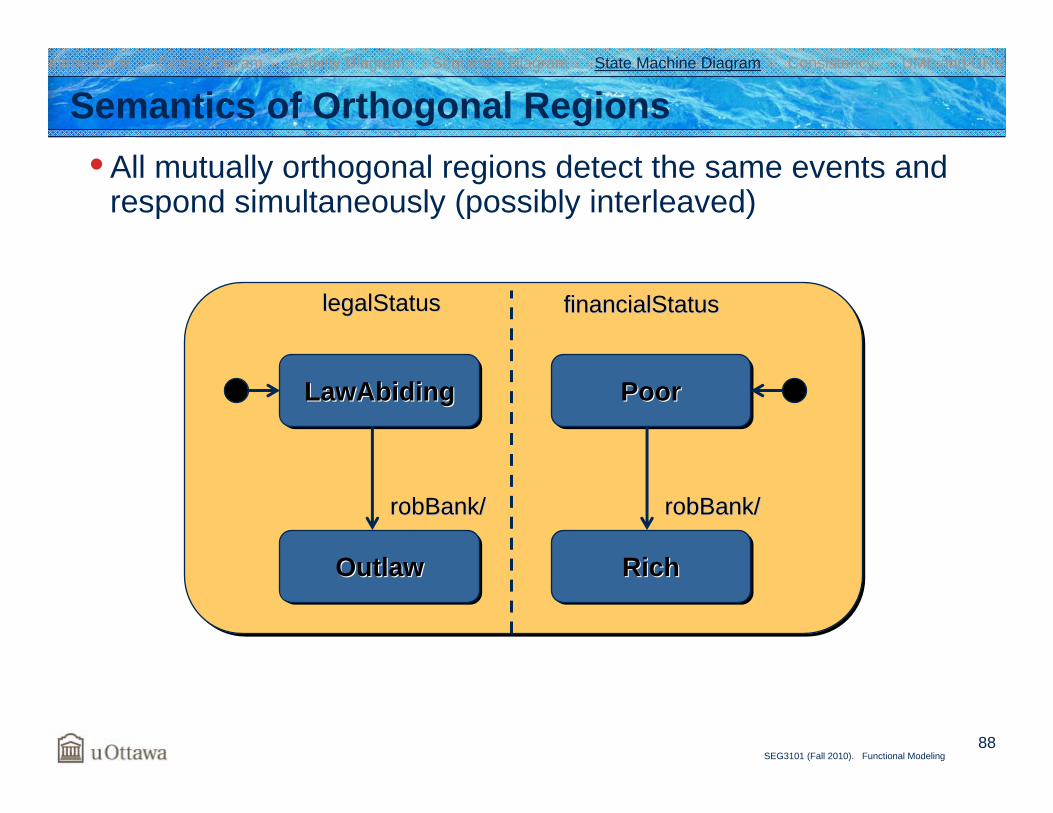
Semantics of Orthogonal Regions• All mutually orthogonal regions detect the same events and
respond simultaneously (possibly interleaved)
robBankrobBank// robBankrobBank//
Introduction Class Diagram Activity Diagram Sequence Diagram State Machine Diagram Consistency UML and URN
89SEG3101 (Fall 2010). Functional Modeling
Catch22Catch22Catch22sanityStatussanityStatus flightStatusflightStatus
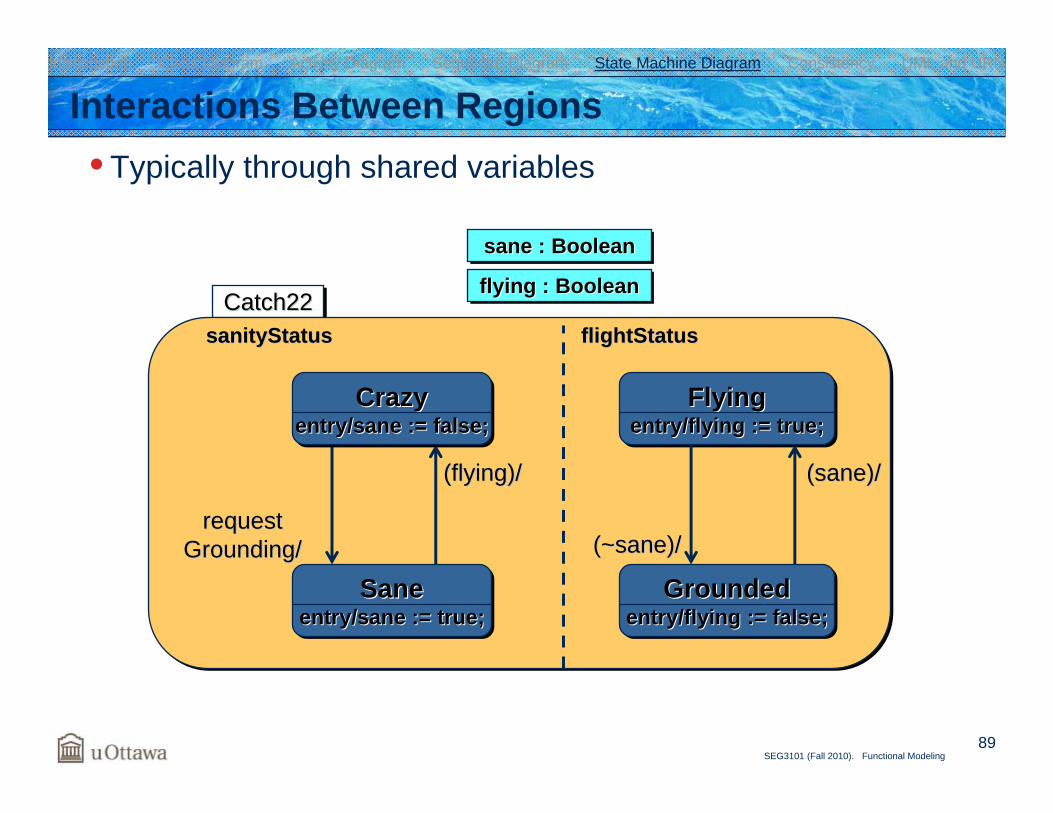
Interactions Between Regions• Typically through shared variables
(flying)/(flying)/
Crazyentry/sane := false;
CrazyCrazyentry/sane := false;entry/sane := false;
Saneentry/sane := true;
SaneSaneentry/sane := true;entry/sane := true;
requestrequestGrounding/Grounding/
Flyingentry/flying := true;
FlyingFlyingentry/flying := true;entry/flying := true;
Groundedentry/flying := false;
GroundedGroundedentry/flying := false;entry/flying := false;
(sane)/(sane)/
(~sane)/(~sane)/
sane : Booleansane : Booleansane : Boolean
flying : Booleanflying : Booleanflying : Boolean
Introduction Class Diagram Activity Diagram Sequence Diagram State Machine Diagram Consistency UML and URN
90SEG3101 (Fall 2010). Functional Modeling
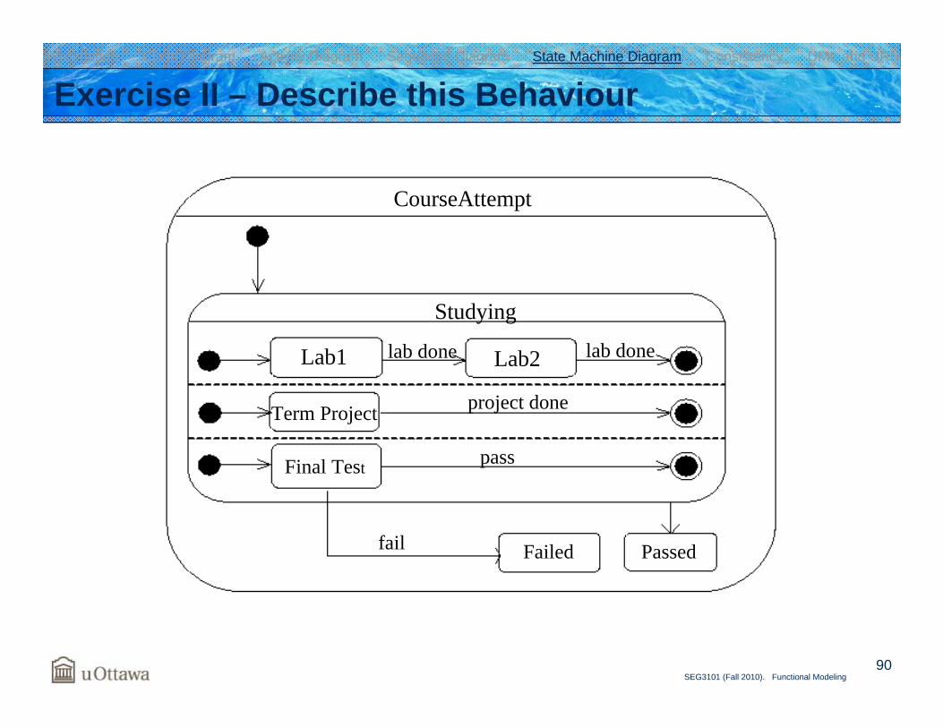
Exercise II – Describe this Behaviour
CourseAttempt
Studying
Lab1 Lab2lab done lab done
Term Project
Final Test
project done
pass
fail Failed Passed
Introduction Class Diagram Activity Diagram Sequence Diagram State Machine Diagram Consistency UML and URN
91SEG3101 (Fall 2010). Functional Modeling
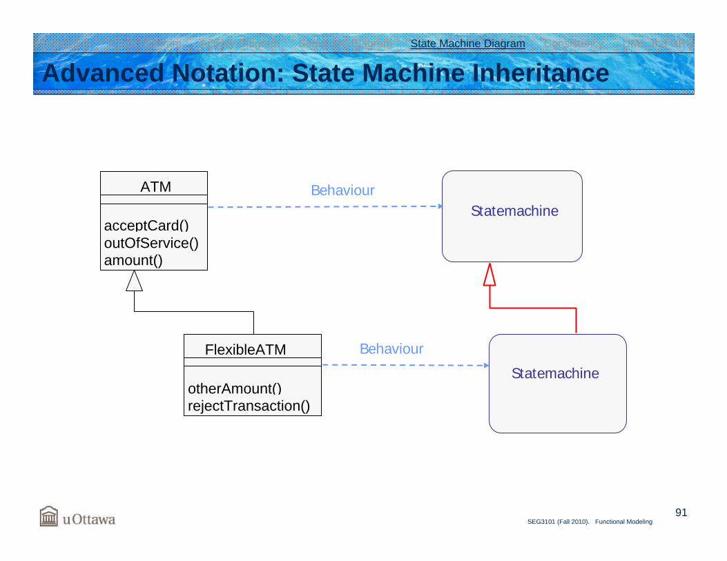
Advanced Notation: State Machine Inheritance
ATM
acceptCard()outOfService()amount()
BehaviourStatemachine
FlexibleATM
otherAmount()rejectTransaction()
Behaviour
Statemachine
Introduction Class Diagram Activity Diagram Sequence Diagram State Machine Diagram Consistency UML and URN
92SEG3101 (Fall 2010). Functional Modeling
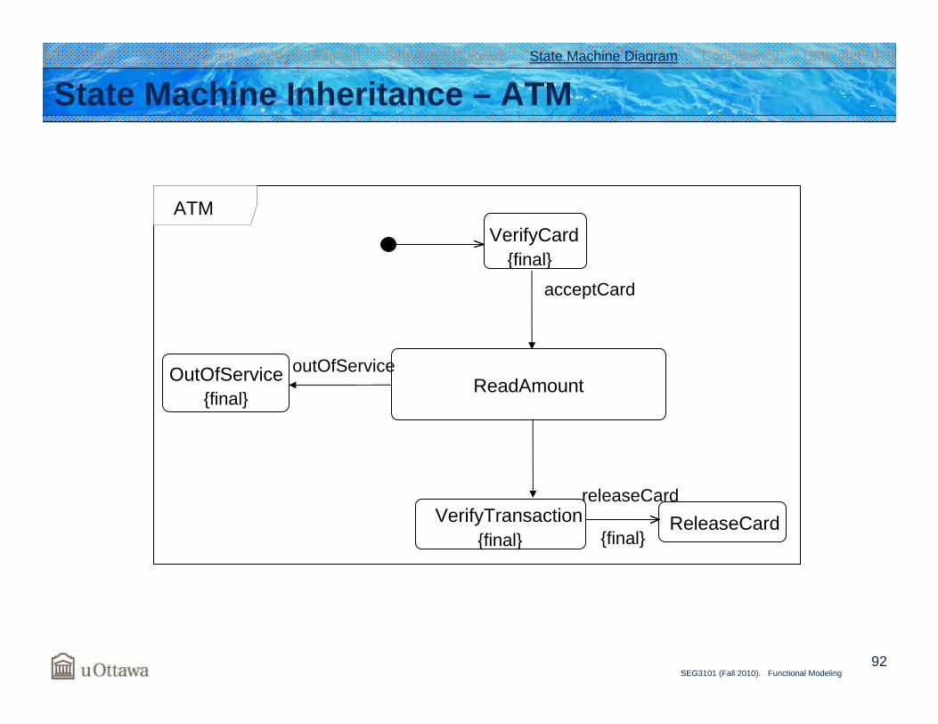
State Machine Inheritance – ATM
VerifyCard
ReadAmount
acceptCard
ReleaseCardVerifyTransaction
outOfService
releaseCard
OutOfService
{final}
{final}
{final}
{final}
ATM
Introduction Class Diagram Activity Diagram Sequence Diagram State Machine Diagram Consistency UML and URN
93SEG3101 (Fall 2010). Functional Modeling
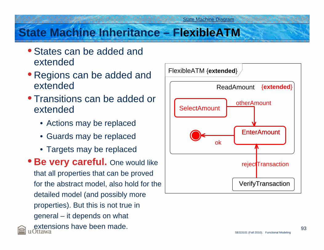
State Machine Inheritance – FlexibleATM• States can be added and
extended• Regions can be added and
extended• Transitions can be added or
extended• Actions may be replaced• Guards may be replaced• Targets may be replaced
• Be very careful. One would like that all properties that can be proved for the abstract model, also hold for the detailed model (and possibly more properties). But this is not true in general – it depends on what extensions have been made.
ReadAmount
EnterAmount
SelectAmount
VerifyTransactionVerifyTransaction
EnterAmountok
otherAmount
rejectTransaction
{extended}
FlexibleATM {extended}
Introduction Class Diagram Activity Diagram Sequence Diagram State Machine Diagram Consistency UML and URN
94SEG3101 (Fall 2010). Functional Modeling
Door {protocol}
[doorWay.isEmpty()] close/
open/
create/ opened closed
locked
lock/unlock/
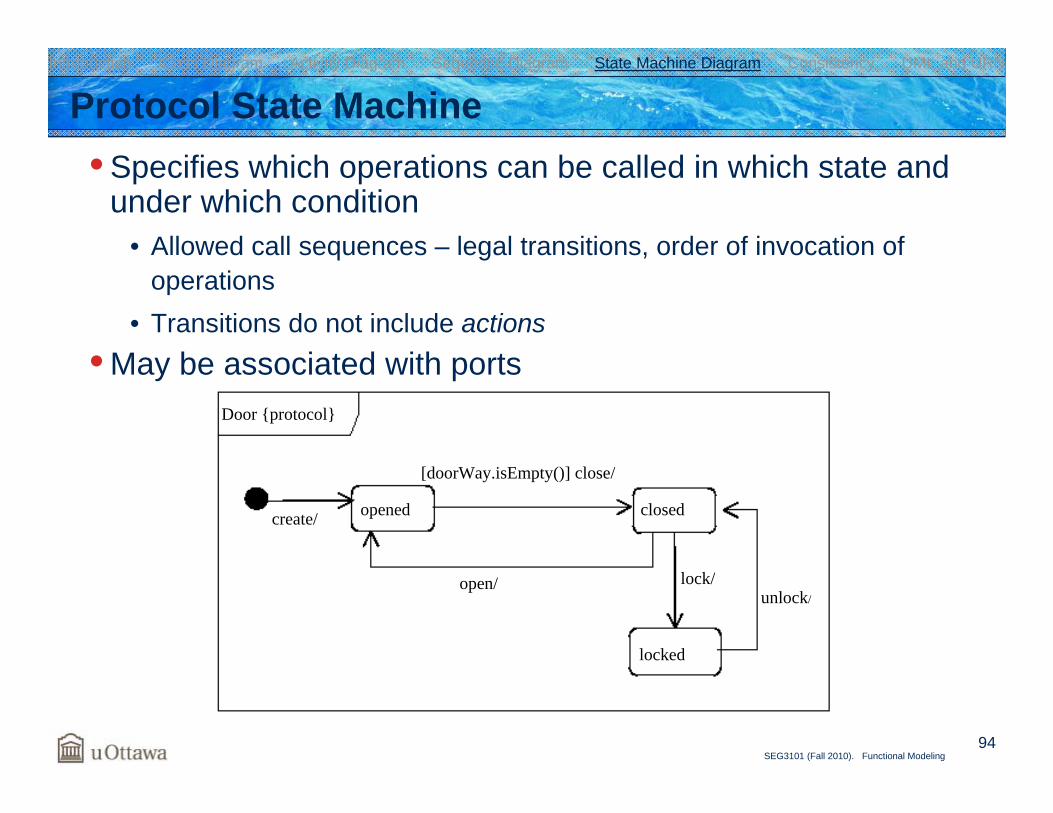
Protocol State Machine• Specifies which operations can be called in which state and
under which condition• Allowed call sequences – legal transitions, order of invocation of
operations• Transitions do not include actions
• May be associated with ports
Introduction Class Diagram Activity Diagram Sequence Diagram State Machine Diagram Consistency UML and URN
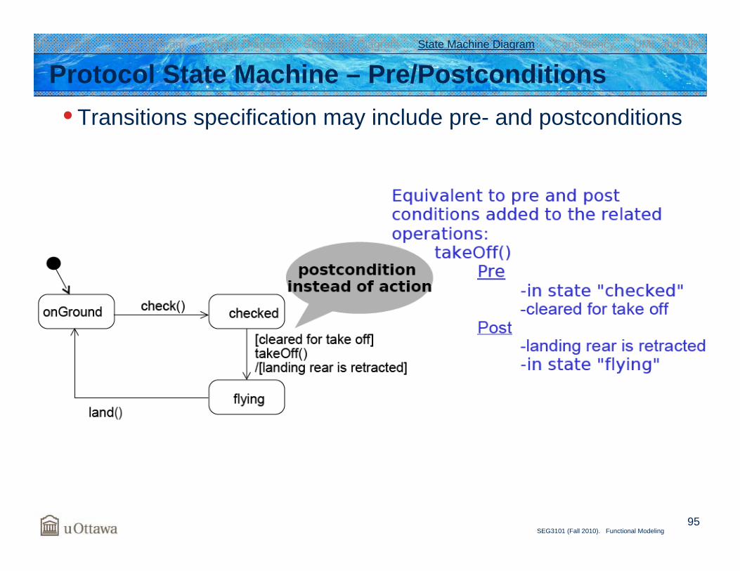
95SEG3101 (Fall 2010). Functional Modeling
Protocol State Machine – Pre/Postconditions• Transitions specification may include pre- and postconditions
Introduction Class Diagram Activity Diagram Sequence Diagram State Machine Diagram Consistency UML and URN
96SEG3101 (Fall 2010). Functional Modeling
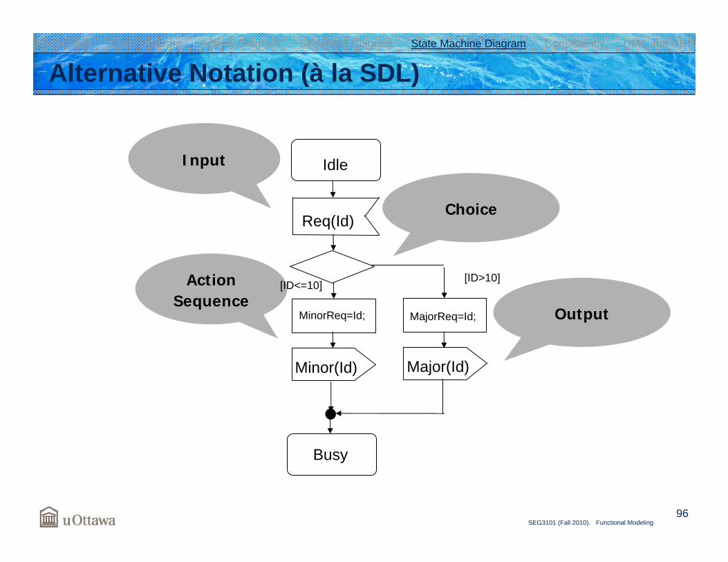
Alternative Notation (à la SDL)
Choice
ActionSequence
Idle
Req(Id)
MinorReq=Id; MajorReq=Id;
[ID<=10] [ID>10]
Minor(Id) Major(Id)
Busy
Introduction Class Diagram Activity Diagram Sequence Diagram State Machine Diagram Consistency UML and URN
Output
Input

State Machine-Based Analysis
98SEG3101 (Fall 2010). Functional Modeling
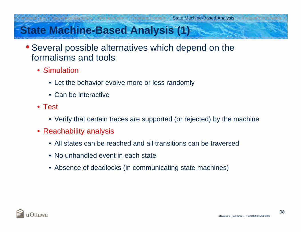
State Machine-Based Analysis (1)• Several possible alternatives which depend on the
formalisms and tools• Simulation
• Let the behavior evolve more or less randomly
• Can be interactive
• Test• Verify that certain traces are supported (or rejected) by the machine
• Reachability analysis• All states can be reached and all transitions can be traversed
• No unhandled event in each state
• Absence of deadlocks (in communicating state machines)
Introduction Structured Analysis OO Analysis Problem Frames State Machine-Based Analysis Triage/Prioritization
99SEG3101 (Fall 2010). Functional Modeling
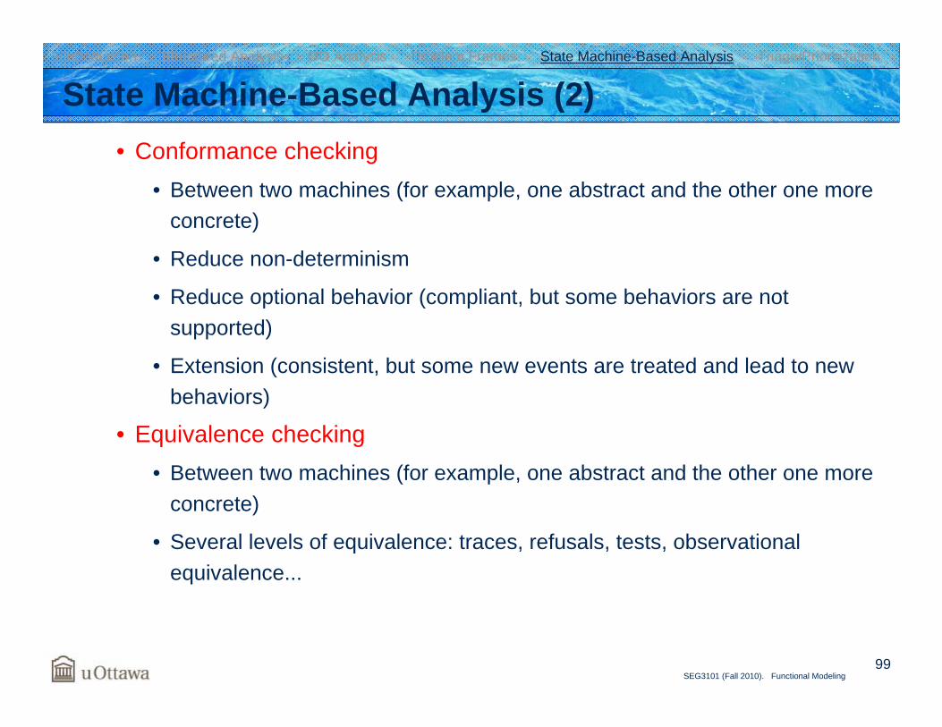
State Machine-Based Analysis (2)• Conformance checking
• Between two machines (for example, one abstract and the other one more concrete)
• Reduce non-determinism
• Reduce optional behavior (compliant, but some behaviors are not supported)
• Extension (consistent, but some new events are treated and lead to new behaviors)
• Equivalence checking• Between two machines (for example, one abstract and the other one more
concrete)
• Several levels of equivalence: traces, refusals, tests, observational equivalence...
Introduction Structured Analysis OO Analysis Problem Frames State Machine-Based Analysis Triage/Prioritization
100SEG3101 (Fall 2010). Functional Modeling
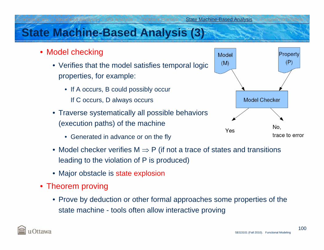
State Machine-Based Analysis (3)• Model checking
• Verifies that the model satisfies temporal logic properties, for example:
• If A occurs, B could possibly occurIf C occurs, D always occurs
• Traverse systematically all possible behaviors (execution paths) of the machine
• Generated in advance or on the fly
• Model checker verifies M ⇒ P (if not a trace of states and transitions leading to the violation of P is produced)
• Major obstacle is state explosion
• Theorem proving• Prove by deduction or other formal approaches some properties of the
state machine - tools often allow interactive proving
Introduction Structured Analysis OO Analysis Problem Frames State Machine-Based Analysis Triage/Prioritization

![Requirements Elicitation Techniques - Engineeringbochmann/SEG3101/Notes...5 SEG3101 (Fall 2010). Requirements Elicitation Techniques Comparison of Data-Gathering Techniques1 [1] Preece,](https://img.pdfslide.us/doc/110x75/5ed467522ef50129625126d4/requirements-elicitation-techniques-engineering-bochmannseg3101notes-5-seg3101.jpg)