Embed Size (px)
Citation preview
HYDRAULIC ENGINEERING SEEPAGE FLOW
171
BASIC KNOWLEDGE
In hydrology, seepage flow refers to the flow of a fluid (water) in permeable soil layers such as sand. The fluid fills the pores in the unsaturated bottom layer and moves into the deeper layers as a result of the effect of gravity. The soil has to be permeable so that the seepage water is not stored.
The permeability of the soil is described by the permeability coefficient kf in m/s and is dependent on the grain size and the useful pore space. In less permeable soils the seepage water can be stored temporarily. If the seepage water encounters an impermeable soil layer or impermeable rock, seepage will no longer take place and the seepage water accumulates permanently. Such underground water accumulations are known as groundwater.
We talk about groundwater when the water resource is available all year round. It is called accumulated water if the water resource only occurs for part of the year, for example after the snow melts or after heavy precipitation over compressed soil layers.
Groundwater is a natural commodity that is used for drinking and mineral water. Furthermore, it repre-sents an important buffer in the total water cycle.
SEEPAGE FLOW
Different types of groundwater:
a water-unsaturated, aerated soil layer,b water-saturated soil layer, all pores are filled with water;
1 seepage water,2 groundwater,3 impermeable soil layer (rock)
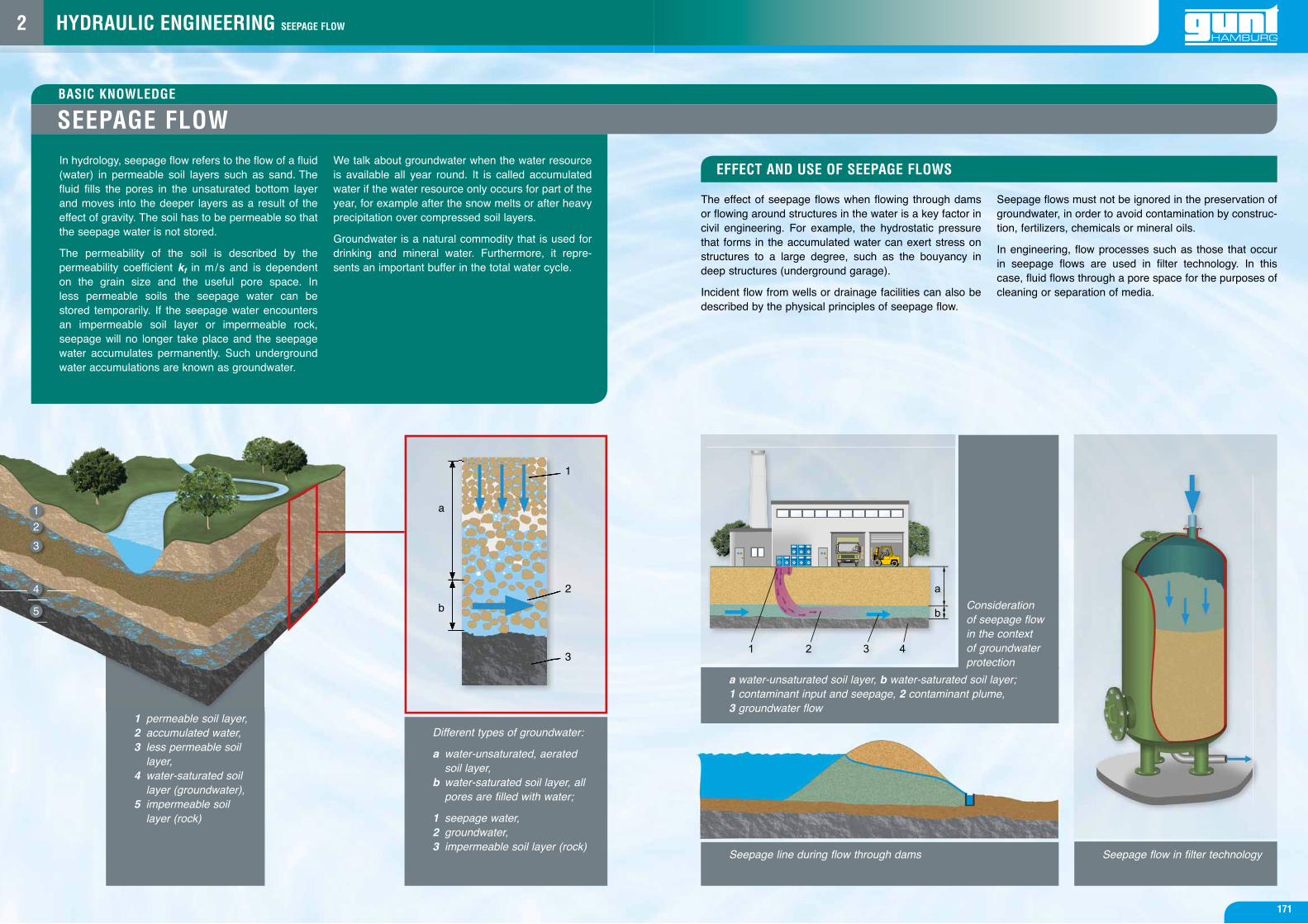
Seepage flow in filter technology
1 permeable soil layer,2 accumulated water,3 less permeable soil layer,4 water-saturated soil layer (groundwater),5 impermeable soil layer (rock)
Seepage line during flow through dams
a water-unsaturated soil layer, b water-saturated soil layer;1 contaminant input and seepage, 2 contaminant plume,3 groundwater flow
Consideration of seepage flow in the context of groundwater protection
The effect of seepage flows when flowing through dams or flowing around structures in the water is a key factor in civil engineering. For example, the hydrostatic pressure that forms in the accumulated water can exert stress on structures to a large degree, such as the bouyancy in deep structures (underground garage).
Incident flow from wells or drainage facilities can also be described by the physical principles of seepage flow.
Seepage flows must not be ignored in the preservation of groundwater, in order to avoid contamination by construc-tion, fertilizers, chemicals or mineral oils.
In engineering, flow processes such as those that occur in seepage flows are used in filter technology. In this case, fluid flows through a pore space for the purposes of cleaning or separation of media.
EFFECT AND USE OF SEEPAGE FLOWS
a
1
2
3
b
1
2
3
4
5
2
FLOW PROCESSES IN SOILS
HYDRAULIC ENGINEERING SEEPAGE FLOW
173
The flow processes take place in the water-saturated soil layers, the groundwater and accumulated water, as well as above the groundwater, in the seepage water.
The cause of water movements in the soil are differences in potential. In this case, the water always moves from points of higher potential, i.e. higher potential energy, to points with lower potential. The water moves until an equi-librium between the potentials is established.
Precipitation, groundwater extraction and evapotranspi-ration: evaporation from the free surface and release of water vapour from plants constantly disrupt a potential equilibrium. Soil water is rarely in a static state of equilib-rium. The movement of water also depends on the perme-ability of the soil being flowed through.
The permeability is described by the coefficient of perme-ability kf in m/s and is dependent on the grain size and the useful pore space.
Due to the inhomogeneity of the soil flowed through, it is extremely difficult to accurately determine the flow processes. Therefore idealised conditions are assumed when calculating the flow processes. For the majority of the problems that occur, Darcy’s law is sufficiently accurate.
According to Darcy, the filtration velocity v is propor-tional to the specific energy Δh that is removed over the length L. The dimensionless variable Δh/L is denoted as the hydraulic gradient i. Darcy’s law is:
The application of Darcy’s law assumes a homogene-ous substrate for the entire flow area, in which there is generally a laminar flow with Reynolds numbers 1-10.
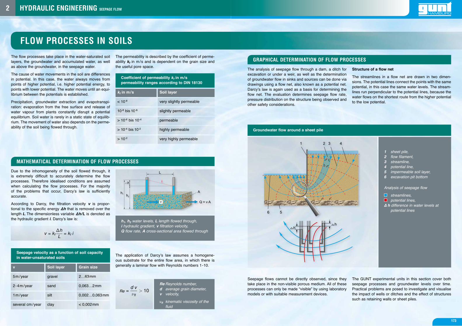
The analysis of seepage flow through a dam, a ditch for excavation or under a weir, as well as the determination of groundwater flow in sinks and sources can be done via drawings using a flow net, also known as a potential net. Darcy’s law is again used as a basis for determining the flow net. The evaluation determines seepage flow rate, pressure distribution on the structure being observed and other safety considerations.
Structure of a flow net
The streamlines in a flow net are drawn in two dimen-sions. The potential lines connect the points with the same potential, in this case the same water levels. The stream-lines run perpendicular to the potential lines, because the water flows on the shortest route from the higher potential to the low potential.
Seepage flows cannot be directly observed, since they take place in the non-visible porous medium. All of these processes can only be made “visible” by using laboratory models or with suitable measurement devices.
The GUNT experimental units in this section cover both seepage processes and groundwater levels over time. Practical problems are posed to investigate and visualise the impact of wells or ditches and the effect of structures such as retaining walls or sheet piles.
MATHEMATICAL DETERMINATION OF FLOW PROCESSES
GRAPHICAL DETERMINATION OF FLOW PROCESSES
v
kf in m /s
5m /year
< 10-8
2-4m /year
10-8 bis 10-6
1m /year
> 10-6 bis 10-4
several cm /year
> 10-4 bis 10-2
> 10-2
Soil layer
gravel
sand
silt
clay
Soil layer
very slightly permeable
slightly permeable
permeable
highly permeable
very highly permeable
Grain size
2…63mm
0,063…2mm
0,002…0,063mm
< 0,002mm
h1, h2 water levels, L length flowed through, i hydraulic gradient, v filtration velocity,Q flow rate, A cross-sectional area flowed through
Re Reynolds number,d average grain diameter,v velocity,
ofl kinematic viscosity of the fluid
1 sheet pile,2 flow filament,3 streamline,4 potential line,5 impermeable soil layer,6 excavation pit bottom
Analysis of seepage flow
streamlines, potential lines,
∆ h difference in water levels at potential lines
Seepage velocity as a function of soil capacity in water-unsaturated soils
Coefficient of permeability kf in m/s permeability ranges according to DIN 18130
Groundwater flow around a sheet pile
v = kfΔhL
= kf i
=d vνfl
> 10Re
2