Embed Size (px)
Citation preview
SEEPAGE CUT-OFFS FOR LEVEES AND DAMS: THE TECHNOLOGY REVIEW
Dr. Donald A. Bruce1
Abstract
Seepage through and under existing levees and embankment dams is a major threat to such structures all across the country, and programs of unprecedented scale have been initiated to remediate this problem. The paper provides a technology review of the various methods used to install such cut-offs, in both rock and soil conditions. These technologies are subdivided as follows: • Category 1 cut-offs involve backfilling of a trench or shaft previously excavated under
bentonite slurry or similar supporting medium. Examples include the use of backhoes, grabs, hydromills and secant piles.
• Category 2 cut-offs involve the mixing of the fill and/or foundation soils in situ. Examples include conventional (i.e., vertical axis) Deep Mixing, the TRD method and CSM method.
For each, the pros and cons, methodologies, applicability and budget costs are provided, as are details from recent case histories and a comprehensive bibliography.
INTRODUCTION Cut-offs to prevent seepage and/or internal erosion are an integral part of many dam and levee remediation projects. For example, Bruce et al. (2006) reported on 22 North American dams which had been remediated between 1975 and 2004 with a major cut-off of some type, while currently over half a billion dollars worth of deep concrete diaphragm walls are under contract in various major dams in the U.S. alone. Such cut-offs remain, of course, common features in the design and construction of new structures. Whereas attention is typically — and appropriately — drawn to these very high profile projects wherein the depth and complexity of the work are extraordinarily impressive, there is an equally important volume of cut-off construction associated with levee remediation. For instance, the U.S. Army Corps of Engineers, together with local partners has, for almost two decades, been remediating the levees in Sacramento, California, the work at Herbert Hoover Dike, around Lake Okeechobee in Florida, is now fully underway, while equally ambitious projects are imminent in New Orleans. Cut-offs for levees are typically shallower than those for dams, for obvious reasons associated with the height of the levee itself and the nature of the foundation materials: there is no call to penetrate one or two hundred feet of embankment material and then continue for another hundred feet into rock, often both hard and abrasive on the one hand, and containing massive karstic features on the other. However, the engineering requirement for a levee cut-off to have acceptable permeability, strength, deformability, homogeneity, continuity and durability does present challenges to the engineering community, especially when it is borne in mind that although such cut-offs are typically less than 100 feet in depth, they may well extend laterally for tens of thousands of feet.
_____________________________ 1 President, Geosystems, L.P., P.O. Box 237, Venetia, PA 15367, U.S.A.; Phone (724) 942-0570; Fax: (724) 942-1911;
Email: [email protected].
The purpose of this paper is to provide a comparative review of the various technologies which are being used, or can be foreseen to be used, to construct cut-offs through levees and dams. There are many ways to classify and present these technologies, and in this paper, the following simple classification has been adopted: • Category 1 cut-offs are created by backfilling a trench or shaft excavated under a bentonite
slurry or similar supporting medium. • Category 2 cut-offs are created by mixing the fill and/or foundation soils in situ. Regarding Category 1, most levee cut-off work is conducted in a continuous and laterally progressive fashion by backhoe. In contrast, dam cut-offs are usually constructed by the panel method using clamshell and/or hydromill technologies. In certain conditions – typically karstic limestone – the cut-off can be constructed by overlapping large diameter columns installed in a Primary-Secondary, secant fashion, or by the “Arapuni” method (Gillon and Bruce, 2003). The oldest method under Category 2 is the conventional Deep Mixing Method (DMM) using vertical mixing augers equipped with mixing blades. More recently, the goal of producing high quality “soilcrete” in situ has been addressed by two new technologies, namely the Japanese TRD (Trench Remixing and Cutting Deep) Method, and the Franco-German CSM (Cutter Soil Mix) Method and its Italian sister, CTJet.
CATEGORY 1 CUT-OFFS (EXCAVATION AND BACKFILL) General Comment The intrinsic advantage of such walls is that the resultant cut-off material (i.e., the “backfill”) can be engineered to provide an extremely wide range of properties, independent of the native material through which the cut-off is to be excavated. This ability is so fundamental that the actual cut-offs are primarily called after the materials themselves, as opposed to the method of excavation: • conventional concrete walls • plastic concrete walls • cement-bentonite walls (CB) • soil-bentonite walls (SB) • soil-cement-bentonite walls (SCB) In all cases except CB walls, excavation is conducted under bentonite (or polymer) slurry which is thereafter displaced out of the trench or panel by the backfill material of choice. It is generally believed that the concept of excavating under a bentonitic supporting slurry was first developed by Veder, in Austria, in 1938. The relationship between backfill material and excavation method is summarized below.
TYPE OF BACKFILL EXCAVATION METHODCLAMSHELL HYDROMILL BACKHOE SECANT PILES
Conventional Concrete Typical Typical Not feasible Typical Plastic Concrete Feasible Feasible Not conducted Rare CB Feasible Feasible Common Not conducted SB Not conducted Not conducted Very common Not conducted SCB Very Rare Very Rare Common Not conducted
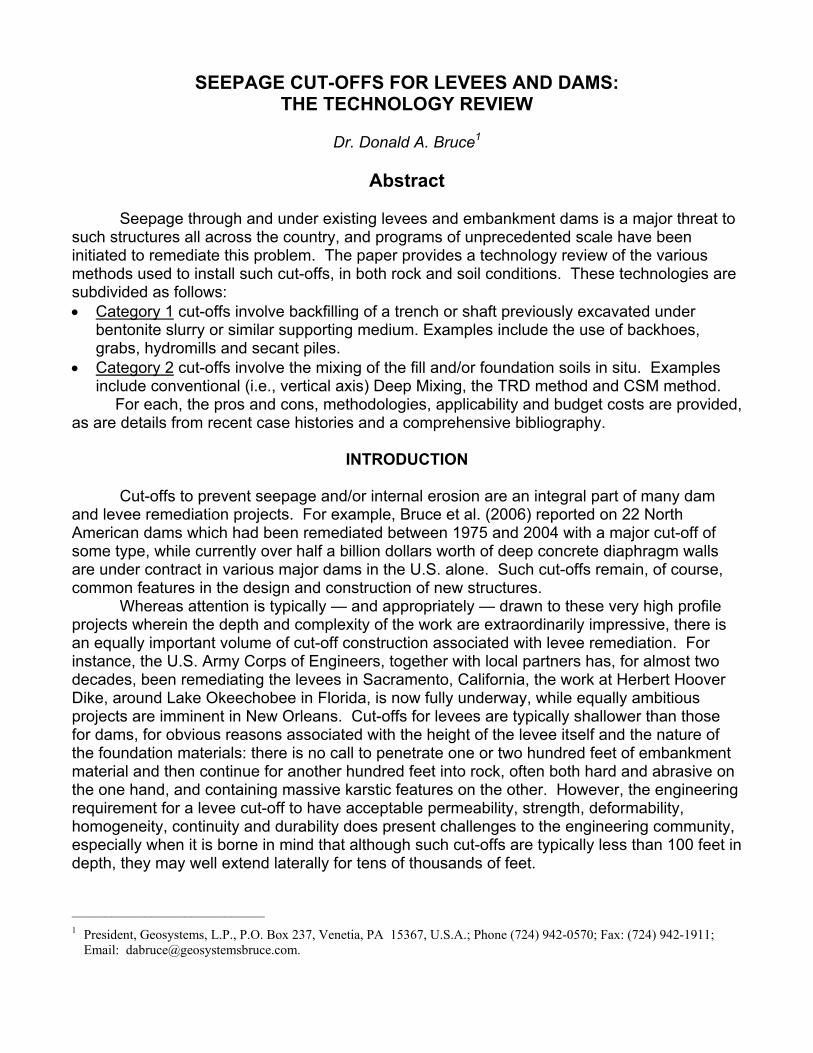
Excavation Methods Details of the various excavation methods are provided in older fundamental texts such as Xanthakos (1979) and ASTM (1992), while Bruce et al. (2008) summarize case histories of more recent vintage. Much valuable information may also be obtained in the websites of the major contractors and equipment manufacturers. The following notes are provided by way of introduction, and perspective. It is often the case that all three techniques may be used on the same project: the backhoe to excavate a “pre-trench,” say 20-40 feet deep, the clamshell to excavate through unobstructed fill or soil, and the hydromill to cut into the underlying or adjacent rock. Furthermore, the current cut-off installation at Wolf Creek Dam, KY, features a combination of panel wall (by clamshell and hydromill) and secant pile technologies, such are the challenges posed by the geological conditions and dam safety concerns during construction. Clamshell The technology was first practiced by Rodio on a project at Bondeno on the River Po in Italy in 1953 and quickly spread throughout Europe as a very adaptable method for constructing deep foundation systems. The first Canadian application was in 1957 and the first use in the U.S. was in 1962. The first example for dam remediation appears to have been the seminal project at Wolf Creek Dam, KY between 1975 and 1979. This was in fact a combination of rotary drilling and clamshell excavation techniques. Clamshells (excavating buckets) can be cable-suspended or kelly-mounted, mechanically or hydraulically activated. They are used to excavate panels 16 to 66 inches wide, to maximum depths of about 250 feet depending on the choice of crane. Most cut-offs are 24 to 36 inches wide and less than 150 feet deep. One “bite” is typically 6 to 10 feet long, and Primary panels may consist of one to three bites (Figure 1). The intervening Secondary panel is most typically installed in one bite, with special attention required to assure the cleanliness and integrity of the inter panel joints.
Figure 1. Concrete and plastic concrete slurry wall construction in panels
(Millet et al., 1992).
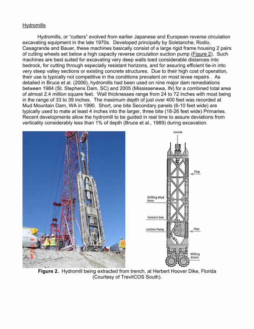
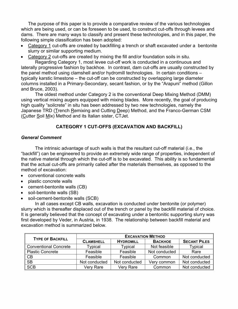
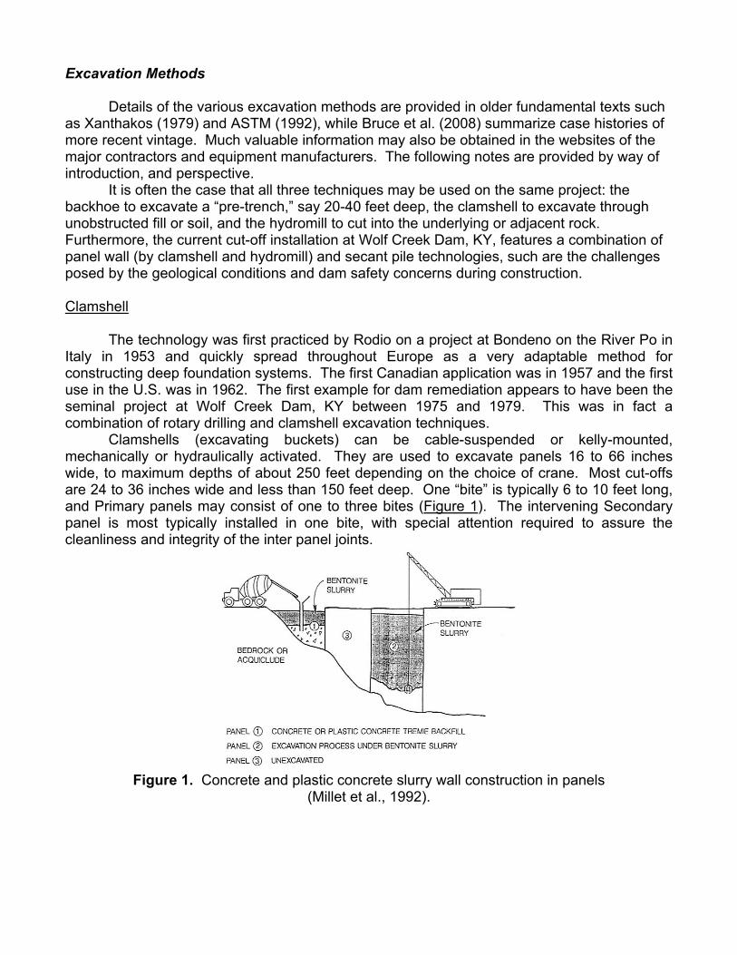
Hydromills Hydromills, or “cutters” evolved from earlier Japanese and European reverse circulation excavating equipment in the late 1970s. Developed principally by Soletanche, Rodio, Casagrande and Bauer, these machines basically consist of a large rigid frame housing 2 pairs of cutting wheels set below a high capacity reverse circulation suction pump (Figure 2). Such machines are best suited for excavating very deep walls toed considerable distances into bedrock, for cutting through especially resistant horizons, and for assuring efficient tie-in into very steep valley sections or existing concrete structures. Due to their high cost of operation, their use is typically not competitive in the conditions prevalent on most levee repairs . As detailed in Bruce et al. (2006), hydromills had been used on nine major dam remediations between 1984 (St. Stephens Dam, SC) and 2005 (Mississenewa, IN) for a combined total area of almost 2.4 million square feet. Wall thicknesses range from 24 to 72 inches with most being in the range of 33 to 39 inches. The maximum depth of just over 400 feet was recorded at Mud Mountain Dam, WA in 1990. Short, one bite Secondary panels (6-10 feet wide) are typically used to mate at least 4 inches into the larger, three bite (18-26 feet wide) Primaries. Recent developments allow the hydromill to be guided in real time to assure deviations from verticality considerably less than 1% of depth (Bruce et al., 1989) during excavation.
Figure 2. Hydromill being extracted from trench, at Herbert Hoover Dike, Florida
(Courtesy of TreviICOS South).
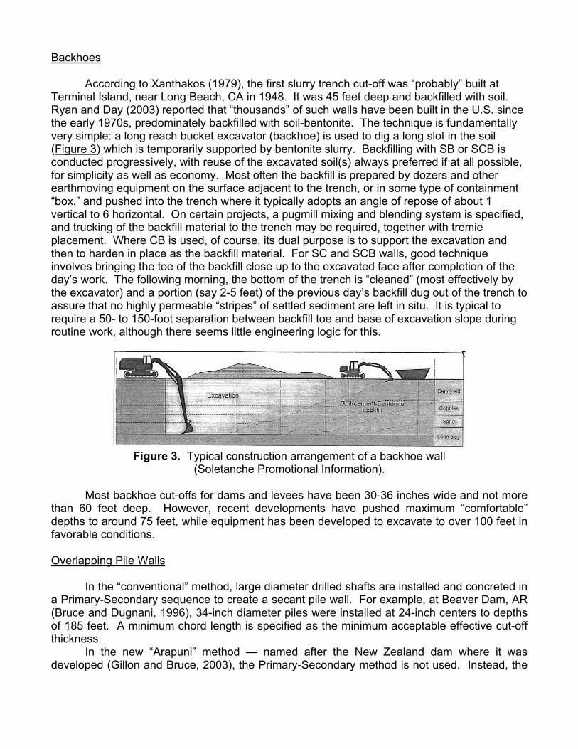
Backhoes According to Xanthakos (1979), the first slurry trench cut-off was “probably” built at Terminal Island, near Long Beach, CA in 1948. It was 45 feet deep and backfilled with soil. Ryan and Day (2003) reported that “thousands” of such walls have been built in the U.S. since the early 1970s, predominately backfilled with soil-bentonite. The technique is fundamentally very simple: a long reach bucket excavator (backhoe) is used to dig a long slot in the soil (Figure 3) which is temporarily supported by bentonite slurry. Backfilling with SB or SCB is conducted progressively, with reuse of the excavated soil(s) always preferred if at all possible, for simplicity as well as economy. Most often the backfill is prepared by dozers and other earthmoving equipment on the surface adjacent to the trench, or in some type of containment “box,” and pushed into the trench where it typically adopts an angle of repose of about 1 vertical to 6 horizontal. On certain projects, a pugmill mixing and blending system is specified, and trucking of the backfill material to the trench may be required, together with tremie placement. Where CB is used, of course, its dual purpose is to support the excavation and then to harden in place as the backfill material. For SC and SCB walls, good technique involves bringing the toe of the backfill close up to the excavated face after completion of the day’s work. The following morning, the bottom of the trench is “cleaned” (most effectively by the excavator) and a portion (say 2-5 feet) of the previous day’s backfill dug out of the trench to assure that no highly permeable “stripes” of settled sediment are left in situ. It is typical to require a 50- to 150-foot separation between backfill toe and base of excavation slope during routine work, although there seems little engineering logic for this.
Figure 3. Typical construction arrangement of a backhoe wall
(Soletanche Promotional Information). Most backhoe cut-offs for dams and levees have been 30-36 inches wide and not more than 60 feet deep. However, recent developments have pushed maximum “comfortable” depths to around 75 feet, while equipment has been developed to excavate to over 100 feet in favorable conditions. Overlapping Pile Walls In the “conventional” method, large diameter drilled shafts are installed and concreted in a Primary-Secondary sequence to create a secant pile wall. For example, at Beaver Dam, AR (Bruce and Dugnani, 1996), 34-inch diameter piles were installed at 24-inch centers to depths of 185 feet. A minimum chord length is specified as the minimum acceptable effective cut-off thickness. In the new “Arapuni” method — named after the New Zealand dam where it was developed (Gillon and Bruce, 2003), the Primary-Secondary method is not used. Instead, the
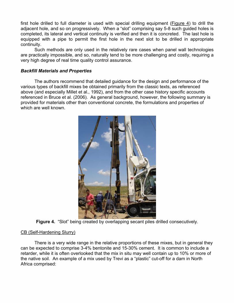
first hole drilled to full diameter is used with special drilling equipment (Figure 4) to drill the adjacent hole, and so on progressively. When a “slot” comprising say 5-8 such guided holes is completed, its lateral and vertical continuity is verified and then it is concreted. The last hole is equipped with a pipe to permit the first hole in the next slot to be drilled in appropriate continuity. Such methods are only used in the relatively rare cases when panel wall technologies are practically impossible, and so, naturally tend to be more challenging and costly, requiring a very high degree of real time quality control assurance. Backfill Materials and Properties The authors recommend that detailed guidance for the design and performance of the various types of backfill mixes be obtained primarily from the classic texts, as referenced above (and especially Millet et al., 1992), and from the other case history specific accounts referenced in Bruce et al. (2006). As general background, however, the following summary is provided for materials other than conventional concrete, the formulations and properties of which are well known.
Figure 4. “Slot” being created by overlapping secant piles drilled consecutively.
CB (Self-Hardening Slurry) There is a very wide range in the relative proportions of these mixes, but in general they can be expected to comprise 3-4% bentonite and 15-30% cement. It is common to include a retarder, while it is often overlooked that the mix in situ may well contain up to 10% or more of the native soil. An example of a mix used by Trevi as a “plastic” cut-off for a dam in North Africa comprised:
– Bentonite: 45-50 kg/m3 of mix – Cement: 200-230 kg/m3 of mix – Water: 900-950 kg/m3 of mix This provided: • k < 10-6 cm/s, decreasing further to 10-7 cm/s and less with time; • UCS ≥ 100 psi; • Strain at failure: 1-2%. Excellent background on specific projects has also been provided by Khoury et al. (1989), Hillis and Van Aller (1992) and Fisher et al. (2005). Blast furnace slag is proving to be a popular substitution for significant weights of Portland cement, especially where relatively low strength and long setting times are required. Plastic Concrete Typical mixes which have been used on recent dam remediation projects include: • Project A
– Water: 400 kg/m3 of mix – Bentonite: 30 kg/m3 of mix – Cement 150 kg/m3 of mix – Sand and gravel: 1,300 kg/m3 of mix This provided k = 10-7 cm/s; UCS = 60-120 psi, and E = 1,400-10,000 psi.
• Project B – Water: 400 kg/m3 of mix – Bentonite: 100 kg/m3 of mix – Cement 100 kg/m3 of mix – Sand and gravel: 1,150 kg/m3 of mix This provided k = 10-6 to 10-7 cm/s; UCS < 60 psi and failure strains of up to 5%.
To repeat, excellent general guidance is provided in Xanthakos (1979), while the standard of care in the design and testing of such mixes was set by Davidson et al. (1992). The mix developed for their project in Canada comprised:
– Water: 400 kg/m3 of mix – Bentonite: 32 kg/m3 of mix – Cement 143 kg/m3 of mix – Fine Aggregate: 798 kg/m3 of mix – Coarse Aggregate: 798 kg/m3 of mix
This provided k = 4x10⁻⁶ to 10-7 cm/s; UCS = 220 psi and an unconfined tangent modulus of 90,000 psi. A “jet erosion” test was also performed on trial mixes to attempt to quantify the mix’s resistance to piping in service.
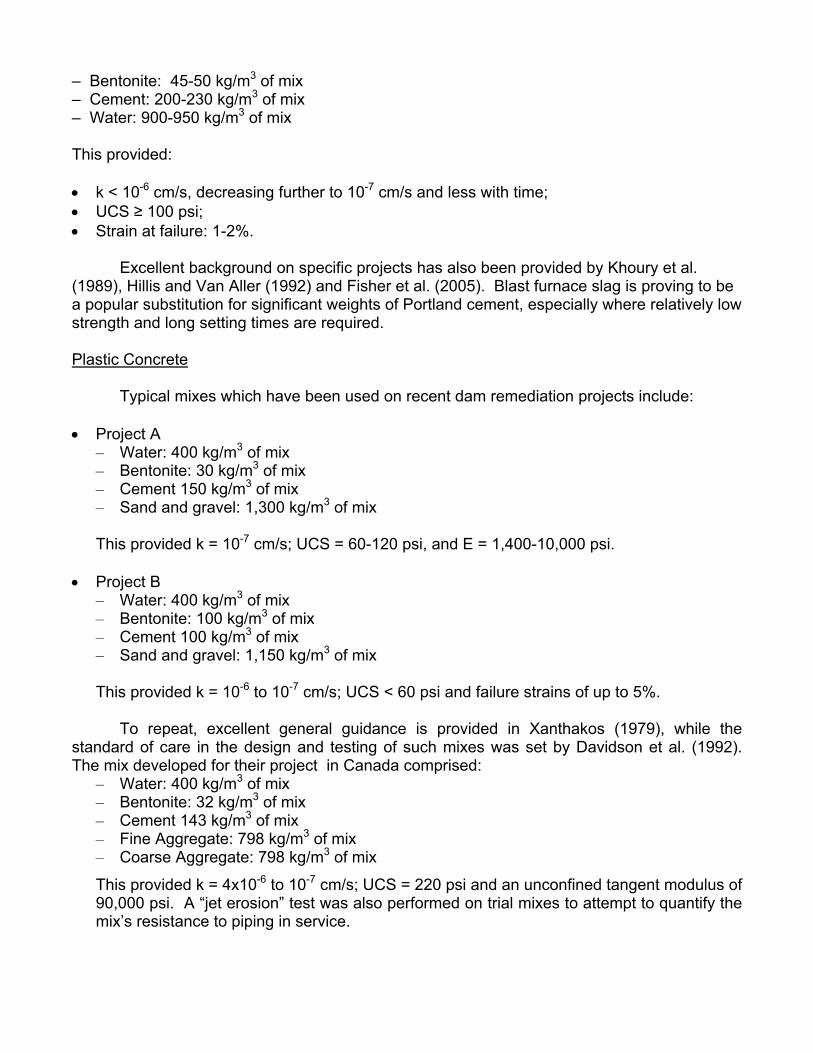
Soil Bentonite (SB) The definitive original paper remains that of D’Appolonia (1980), while the publication by Millet et al. (1992) provided an excellent update. D’Appolonia demonstrated how the permeability of the backfill varies with the gradation of excavated soil and the bentonite content. In particular, the fines contents (and their plasticity) are critical and a minimum limit of 20% is commonly set (including the bentonite content which may be up to 5%). The soil should be uniformly graded, to assure the desired permeability and minimal self-weight compressibility. However, it has not been found useful (Ryan and Day, 2003) to add gravel or coarse sand to a soil which does not naturally have this coarser fraction. Large particles (say > 4 inches) should be removed. A typical mix, suited for easy placement, will have a slump of 3-6 inches, and will provide permeabilities in the range of 10-6 to 5x10⁻⁹ cm/s. Xanthakos (1979) provided typical backfill gradations used at the time (Table 1), while current thinking is to “soften” gradation limits with the exception that between 20 and 60% of fines must be used. Table 1. Typical gradation limits for backfills in the United States
(Xanthakos, 1979).
As with all “excavate and replace” methods, special care must be taken to ensure the bentonite slurry used to support the trench prior to backfilling has acceptable properties during backfilling. These will include a Marsh Cone Viscosity of around 40 seconds, a specific gravity 0.25 less than the backfill’s specific gravity, and a sand content as low as is practical, safe and economic to provide. (Typical values for a trench being dug in sand may be as high as 30% without necessarily impacting the quality and homogeneity of the subsequent wall, provided proper attention is paid during the backfilling operation.) Soil-Cement-Bentonite (SCB) The addition of cement is warranted when a certain minimum strength is required for durability and resistance to erosion. To supplement the background of Xanthakos (1979), the reader is referred to the comprehensive paper by Dinnean and Sheskier (1997) on Twin Buttes Dam, TX. These authors noted that such mixes had been used in seepage cut-offs for the Sacramento levees, and at Sam Rayburn Dam, TX, although in general there had been “limited experience” to that point.
Mix designs featured:
– 4-10% Cement (and/or pozzolan) by dry mass of soil (“aggregate”) – 4-5% Bentonite Slurry (i.e., about 1% by dry weight)
The aggregate was reasonably well graded with a maximum size of 1½ inches and 10-20% fines. The mix needed a continuous-type plant capable of accurate batching and homogeneous mixing. Trucks were used for tremie placement. The mix had a 7- to 10-inch slump, a 28-day UCS of around 100 psi (or twice the potential 120 feet of head differential in service), and a target permeability of 1x10⁻⁶ cm/s. On this project, the slurry had to have a density less than 1.20, a sand content of less than 5%, and a Marsh cone value of less than 45 seconds, prior to SCB placement. Particular Notable Advantages of Category 1 Cut-Offs • The backfill material can be engineered to provide specific properties in order to optimize
construction techniques and satisfy service performance requirements. • A method can be found and/or developed to create cut-offs through all types of soil and fill
and rock (to depths of over 400 feet). • In conditions favoring the backhoe method, unit costs are very low (< $10/sf). However,
deeper walls and in more challenging geotechnical conditions (requiring, say, a hydromill or secant piles), unit costs can be many times higher.
• All the types of excavation methods, and all the types of backfill, have extensive history of use and are supported by a long and comprehensive literature base of successful case histories.
• In very favorable conditions, industrial productivities can be very high (over 3,000 sf per shift for backhoe and over 1,500 sf per shift for clamshell and hydromill). When excavating in very hard rock, productivities will be much lower — by as much as one order or more.
• There is an excellent but relatively shallow pool of experienced specialty contractors in North America.
Particular Potential Drawbacks of Category 1 Cut-Offs • More spoil is created, and the displaced bentonite slurry must be handled and stored
appropriately. • Backhoe walls are commercially very attractive and are somewhat of a “commodity.”
However, QA/QC is always a concern, and the backhoe will not be feasible in obstructed, very dense, or hard ground conditions, or to depths in excess of about 100 feet.
• For the other methods, a main concern is the lateral continuity of the wall in deeper cut-offs, i.e., as reflected in the verticality control of each panel or pile. Furthermore, slurry contaminated joints may remain, if proper care has not been exercised during concrete placement. (This is not an issue, of course, for CB walls, where there is no separate bentonite slurry medium to consider.)
• Poor backfilling procedures may result in pockets of trapped slurry and/or segregation of the backfill.
• Sudden loss of supporting slurry into the formation during excavation or drilling may occur and can potentially create an embankment safety situation.
• Clamshell, hydromill and piling operations need substantial working platform preparations and unrestricted access conditions.
Unit Costs It is extremely difficult to provide definitive guidance, given the huge range of methods, materials and project requirements (such as depth and geological conditions). For example, the backhoe is only used in favorable conditions to moderate depths, whereas the hydromill is typically called upon for cut-offs of relatively great depth and/or to penetrate into resistant bedrock conditions. The following table is provided, to be used with caution and understanding.
CLAMSHELL HYDROMILL BACKHOE SECANT PILE Mob/Demob $100,000-$250,000 $250,000-$500,000 $25,000-$50,000 $100,000-$500,000 Unit Cost $30-$100/sf $50-$250/sf $6-$12/sf $150-$300/sf Overall Verdict Category 1 walls have a long and successful history of usage throughout the U.S. They cover a wide variety of excavation methods and backfill materials and so provide a huge range of options relating to constructability and performance. They include the cheapest (Backhoe) and the most expensive (Secant Pile) cut-offs which can be built for levee or dam remedial purposes.
CATEGORY 2 CUT-OFFS (MIX IN PLACE) DMM (Conventional Deep Mixing) Method Background Although an early variant of DMM was used sporadically in the U.S. from 1954 (the MIP piling technique), contemporary DMM methods used for seepage control date from Japanese developments by Seiko Kogyo beginning in 1972. It should be noted that DMM techniques for improving foundation soils for strength and stability purposes had been developed both in Japan and in Sweden 5 years previously (FHWA 2000, 2001). Japanese cut-off technology was first introduced into the U.S. in 1986 and was further developed by U.S. specialists in several projects thereafter, the biggest being Jackson Lake Dam, WY, Lockington Dam, OH, the Sacramento Levees, CA, and Cushman Dam, WA (Figure 5). DMM is “conventional” in situ soil treatment technology whereby the soil is blended with cementitious and/or other materials referred to as “binders.” For cut-offs, the materials are injected as a fluid grout through hollow, rotating mixing shafts tipped with some type of cutting tool. On any one, tracked, “carrier” the number of vertically mounted shafts can range from 1 to 8, but for cut-offs three or four shaft systems predominate. The type of binder (Wet or Dry), the energy of the grout injection (Rotary only, i.e., low pressure, or Jet-assisted, i.e., high pressure), and the mixing principle (all along the Shaft, or only at the End), characterize the various methods currently in use in the U.S. The original SMW (Soil Mixed Wall) variant is therefore classified generically as WRS.

Lake Cushman Spillway Hoodsport, Washington
Sacramento Levee Reconstruction Sacramento, California
Figure 5. Examples of DMM cut-offs using the Soil Mixed Wall (SMW) variant (Yang 1997).
DMM is “conventional” in situ soil treatment technology whereby the soil is blended with cementitious and/or other materials referred to as “binders.” For cut-offs, the materials are injected as a fluid grout through hollow, rotating mixing shafts tipped with some type of cutting tool. On any one, tracked, “carrier” the number of vertically mounted shafts can range from 1 to 8, but for cut-offs three or four shaft systems predominate. The type of binder (Wet or Dry), the energy of the grout injection (Rotary only, i.e., low pressure, or Jet-assisted, i.e., high pressure), and the mixing principle (all along the Shaft, or only at the End), characterize the various methods currently in use in the U.S. The original SMW (Soil Mixed Wall) variant is therefore classified generically as WRS. Columns are secant (Figure 6), and typically vary in diameter between 20 and 40 inches with the most common dimension being about 32 inches. “Practical” maximum depths in the range of 80-110 feet are commonly claimed (depending on the system), although greater depths are achievable with highly specialized equipment and methods. The continuity of the cut-off is assured by re-penetrating into the inner elements of freshly installed panels, or “strokes.” Grout volume ratios of 30 to over 100% are used, depending on the ground conditions, the desired properties of the soilcrete, and the particular requirements of each DMM variant. Grout volume ratio is defined as the volume of grout injected divided by the volume of wall.
Figure 6. DMM installation sequence (Bahner and Naguib, 1998).
There tends not to be a great deal of vertical movement of the native soil in many cases during mixing, and so “conventional” DMM panels tend to have a range of strengths with depth
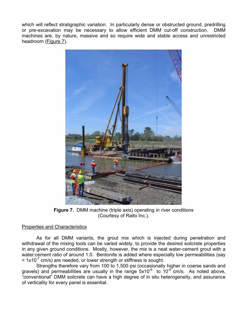
which will reflect stratigraphic variation. In particularly dense or obstructed ground, predrilling or pre-excavation may be necessary to allow efficient DMM cut-off construction. DMM machines are, by nature, massive and so require wide and stable access and unrestricted headroom (Figure 7).
Figure 7. DMM machine (triple axis) operating in river conditions (Courtesy of Raito Inc.).
Properties and Characteristics As for all DMM variants, the grout mix which is injected during penetration and withdrawal of the mixing tools can be varied widely, to provide the desired soilcrete properties in any given ground conditions. Mostly, however, the mix is a neat water-cement grout with a water:cement ratio of around 1.0. Bentonite is added where especially low permeabilities (say < 1x10⁻⁷ cm/s) are needed, or lower strength or stiffness is sought. Strengths therefore vary from 100 to 1,500 psi (occasionally higher in coarse sands and gravels) and permeabilities are usually in the range 5x10⁻⁶ to 10-8 cm/s. As noted above, “conventional” DMM soilcrete can have a high degree of in situ heterogeneity, and assurance of verticality for every panel is essential.
Particular Notable Advantages • Machines impart low vibrations and create moderate noise. • Applicable in most soil conditions. • With appropriate means, methods and controls, cut-offs of reasonable homogeneity and
good continuity can be built. • Productivities can be high – outputs of 2,000 to 3,000 square feet per 10-hour shift are
feasible. • Unit rates are low to moderate ($15-$30/sf) in sympathetic conditions, but markedly higher
in less favorable conditions. • There are several very competent competitors in North America, with good track records. Particular Potential Drawbacks • The equipment is large, heavy and is not compatible with limited headroom or tight access
sites. • The practical maximum depth is limited to about 110 feet. Only vertical diaphragms can be
installed. • DMM is particularly sensitive to soils that are very dense, very stiff or that may have a high
density of boulders. Also, strengths and homogeneity can be challenged in soils with high organic contents, or high plasticity.
• Mobilization costs are relatively high. Unit Costs Mob/demob: $150,000-$500,000.
Unit Price: $15-$30/sf (favorable conditions) Overall Verdict “Conventional” DMM is a well researched and resourced technology which has been used in North America for over 20 years. Compared to more recent DMM variants, such as TRD and CSM, however, it is more sensitive to significant variability in the penetrability and composition of the ground, and the product tends to be less homogeneous. Like all DMM technologies, it has intrinsically a relatively high cost basis (due to the highly specialized large scale equipment) and so will not be competitive when lower technology systems (e.g., backhoe) can be used. TRD (Trench Re-Mixing and Cutting Deep Wall) Method Background This Japanese development was conceived in 1993, was tested for the first time in 1994 and, up to mid-2003, had been used on over 220 projects, mostly after 1997. The TRD machine comprises a crawler mounted base, which provides continuous horizontal movement of a trench cutter, basically comprising a chain saw mounted on a long rectangular section
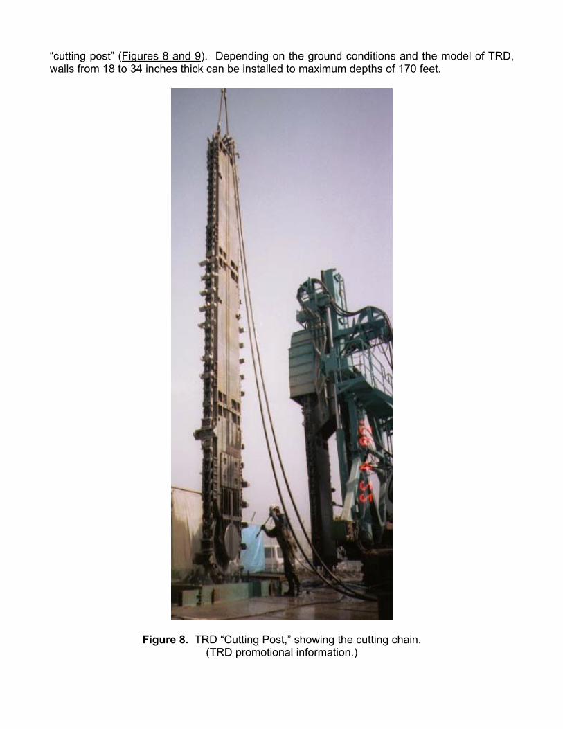
“cutting post” (Figures 8 and 9). Depending on the ground conditions and the model of TRD, walls from 18 to 34 inches thick can be installed to maximum depths of 170 feet.
Figure 8. TRD “Cutting Post,” showing the cutting chain. (TRD promotional information.)
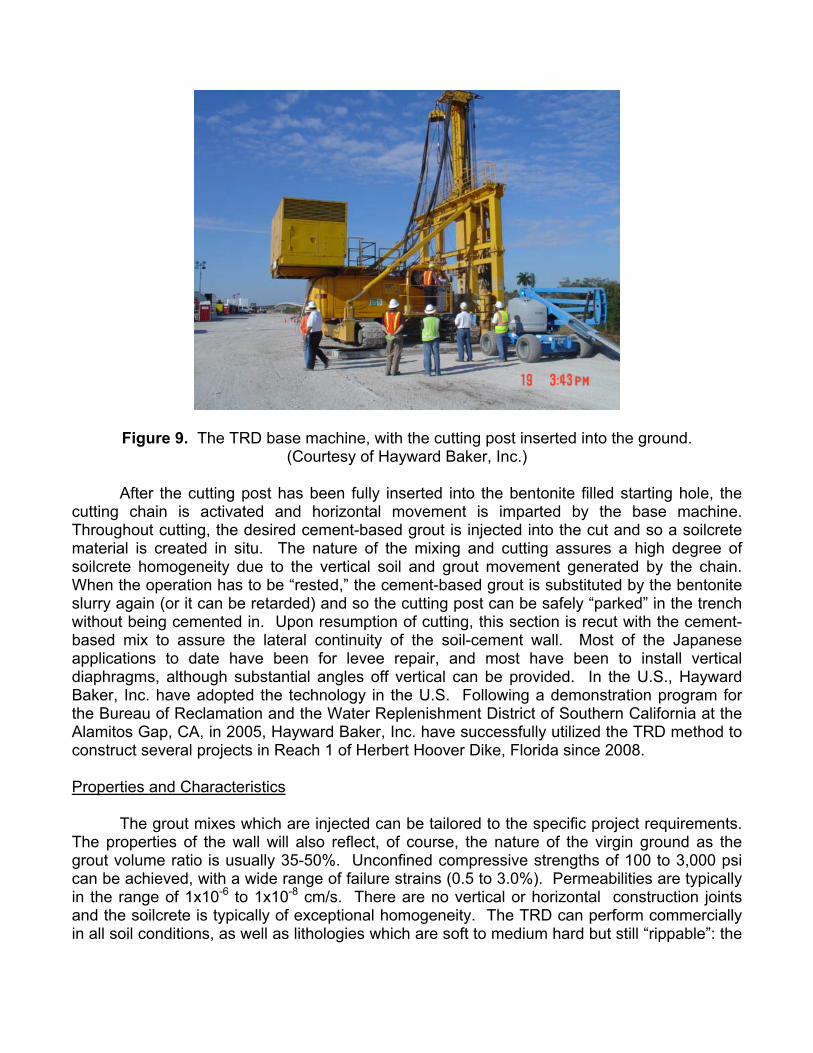
Figure 9. The TRD base machine, with the cutting post inserted into the ground. (Courtesy of Hayward Baker, Inc.)
After the cutting post has been fully inserted into the bentonite filled starting hole, the cutting chain is activated and horizontal movement is imparted by the base machine. Throughout cutting, the desired cement-based grout is injected into the cut and so a soilcrete material is created in situ. The nature of the mixing and cutting assures a high degree of soilcrete homogeneity due to the vertical soil and grout movement generated by the chain. When the operation has to be “rested,” the cement-based grout is substituted by the bentonite slurry again (or it can be retarded) and so the cutting post can be safely “parked” in the trench without being cemented in. Upon resumption of cutting, this section is recut with the cement-based mix to assure the lateral continuity of the soil-cement wall. Most of the Japanese applications to date have been for levee repair, and most have been to install vertical diaphragms, although substantial angles off vertical can be provided. In the U.S., Hayward Baker, Inc. have adopted the technology in the U.S. Following a demonstration program for the Bureau of Reclamation and the Water Replenishment District of Southern California at the Alamitos Gap, CA, in 2005, Hayward Baker, Inc. have successfully utilized the TRD method to construct several projects in Reach 1 of Herbert Hoover Dike, Florida since 2008. Properties and Characteristics The grout mixes which are injected can be tailored to the specific project requirements. The properties of the wall will also reflect, of course, the nature of the virgin ground as the grout volume ratio is usually 35-50%. Unconfined compressive strengths of 100 to 3,000 psi can be achieved, with a wide range of failure strains (0.5 to 3.0%). Permeabilities are typically in the range of 1x10⁻⁶ to 1x10⁻⁸ cm/s. There are no vertical or horizontal construction joints and the soilcrete is typically of exceptional homogeneity. The TRD can perform commercially in all soil conditions, as well as lithologies which are soft to medium hard but still “rippable”: the
cutting teeth are changed in response to the ground conditions. Boulders — as for all DMM techniques — are troublesome, but far less so for the TRD method than the traditional vertical axis machines. Particular Notable Advantages • Provides continuous, homogeneous, joint-free wall through all soil and many rock
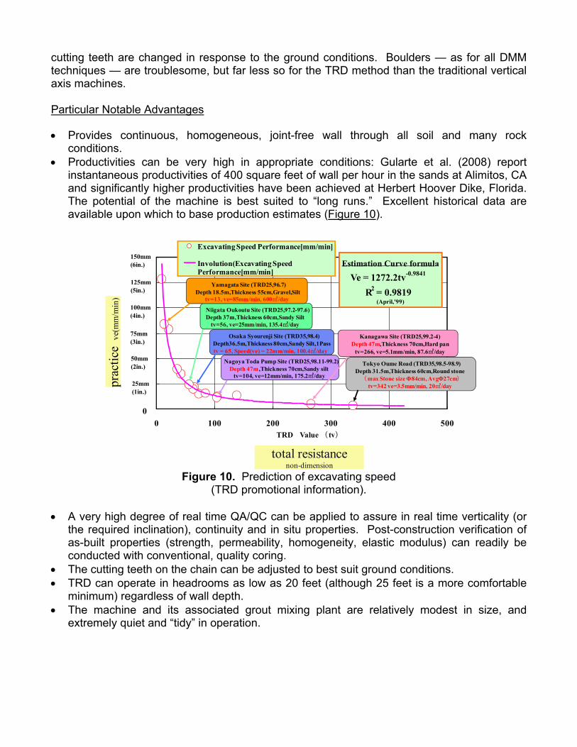
conditions. • Productivities can be very high in appropriate conditions: Gularte et al. (2008) report
instantaneous productivities of 400 square feet of wall per hour in the sands at Alimitos, CA and significantly higher productivities have been achieved at Herbert Hoover Dike, Florida. The potential of the machine is best suited to “long runs.” Excellent historical data are available upon which to base production estimates (Figure 10).
Estimation Curve formula
Ve = 1272.2tv-0.9841
R2 = 0.9819(April,'99)
0
75mm(3in.)
100mm (4in.)
125mm(5in.)
150mm(6in.)
0 100 200 300 400 500TRD Value ( tv)
prac
tice
ve(m
m/m
in)
Excavating Speed Performance[mm/min]
Involution(Excavating SpeedPerformance[mm/min]
Nagoya Toda Pump Site (TRD25,98.11-99.2)Depth 47m,Thickness 70cm,Sandy silt
tv=104, ve=12mm/min, 175.2㎡/day
Tokyo Oume Road (TRD35,98.5-98.9)Depth 31.5m,Thickness 60cm,Round stone(max Stone size Φ84cm, AvgΦ27cm)
tv=342 ve=3.5mm/min, 20㎡/day
Niigata Oukoutu Site (TRD25,97.2-97.6)Depth 37m,Thickness 60cm,Sandy Silt
tv=56, ve=25mm/min, 135.4㎡/day
Yamagata Site (TRD25,96.7)Depth 18.5m,Thickness 55cm,Gravel,Silt
tv=13, ve=85mm/min, 600㎡/day
Osaka Syourenji Site (TRD35,98.4)Depth36.5m,Thickness 80cm,Sandy Silt,1Passtv = 65, Speed(ve) = 22mm/min, 100.4㎡/day
Kanagawa Site (TRD25,99.2-4)Depth 47m,Thickness 70cm,Hard pan
tv=266, ve=5.1mm/min, 87.6㎡/day50mm(2in.)
25mm(1in.)
total resistancenon-dimension
Figure 10. Prediction of excavating speed (TRD promotional information).
• A very high degree of real time QA/QC can be applied to assure in real time verticality (or
the required inclination), continuity and in situ properties. Post-construction verification of as-built properties (strength, permeability, homogeneity, elastic modulus) can readily be conducted with conventional, quality coring.
• The cutting teeth on the chain can be adjusted to best suit ground conditions. • TRD can operate in headrooms as low as 20 feet (although 25 feet is a more comfortable
minimum) regardless of wall depth. • The machine and its associated grout mixing plant are relatively modest in size, and
extremely quiet and “tidy” in operation.
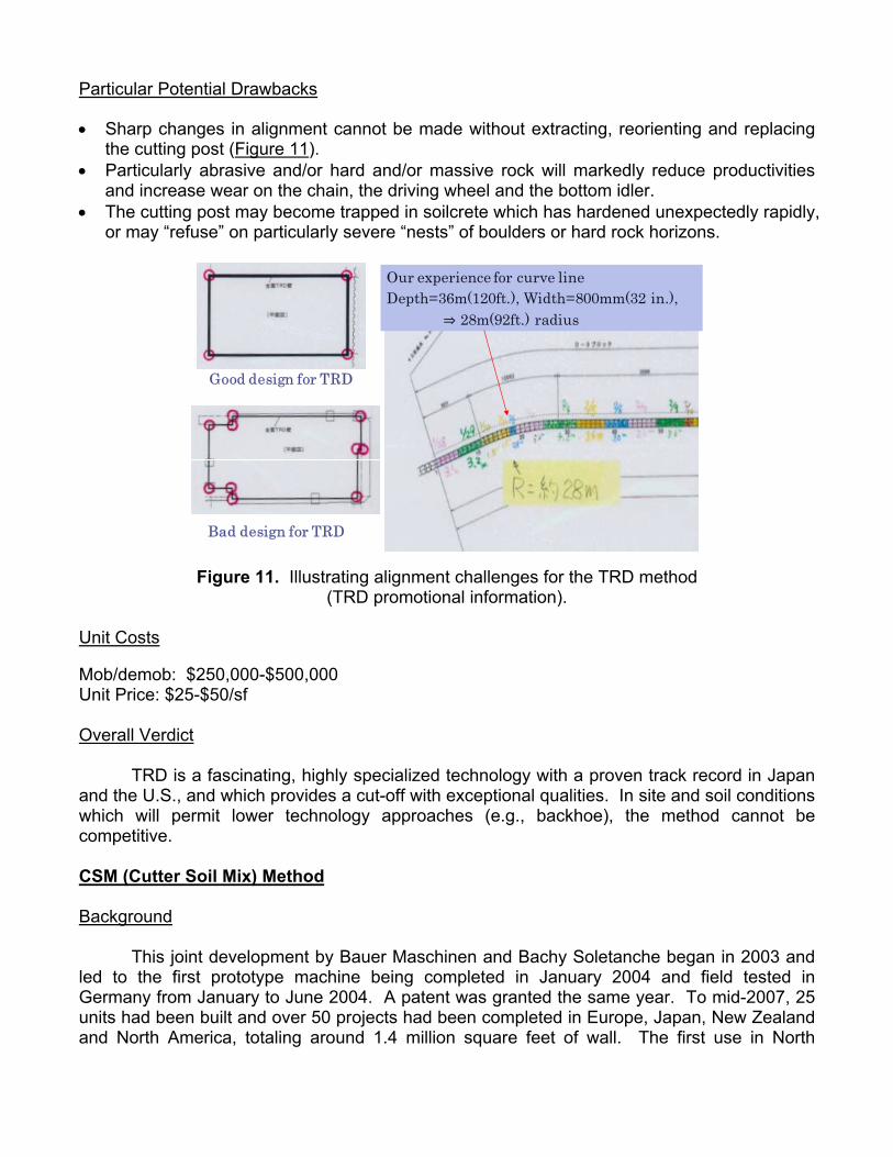
Particular Potential Drawbacks • Sharp changes in alignment cannot be made without extracting, reorienting and replacing
the cutting post (Figure 11). • Particularly abrasive and/or hard and/or massive rock will markedly reduce productivities
and increase wear on the chain, the driving wheel and the bottom idler. • The cutting post may become trapped in soilcrete which has hardened unexpectedly rapidly,
or may “refuse” on particularly severe “nests” of boulders or hard rock horizons.
Our experience for curve lineDepth=36m(120ft.), Width=800mm(32 in.),
28m(92ft.) radius
Good design for TRD
Bad design for TRD
Figure 11. Illustrating alignment challenges for the TRD method (TRD promotional information).
Unit Costs Mob/demob: $250,000-$500,000 Unit Price: $25-$50/sf Overall Verdict TRD is a fascinating, highly specialized technology with a proven track record in Japan and the U.S., and which provides a cut-off with exceptional qualities. In site and soil conditions which will permit lower technology approaches (e.g., backhoe), the method cannot be competitive. CSM (Cutter Soil Mix) Method Background This joint development by Bauer Maschinen and Bachy Soletanche began in 2003 and led to the first prototype machine being completed in January 2004 and field tested in Germany from January to June 2004. A patent was granted the same year. To mid-2007, 25 units had been built and over 50 projects had been completed in Europe, Japan, New Zealand and North America, totaling around 1.4 million square feet of wall. The first use in North
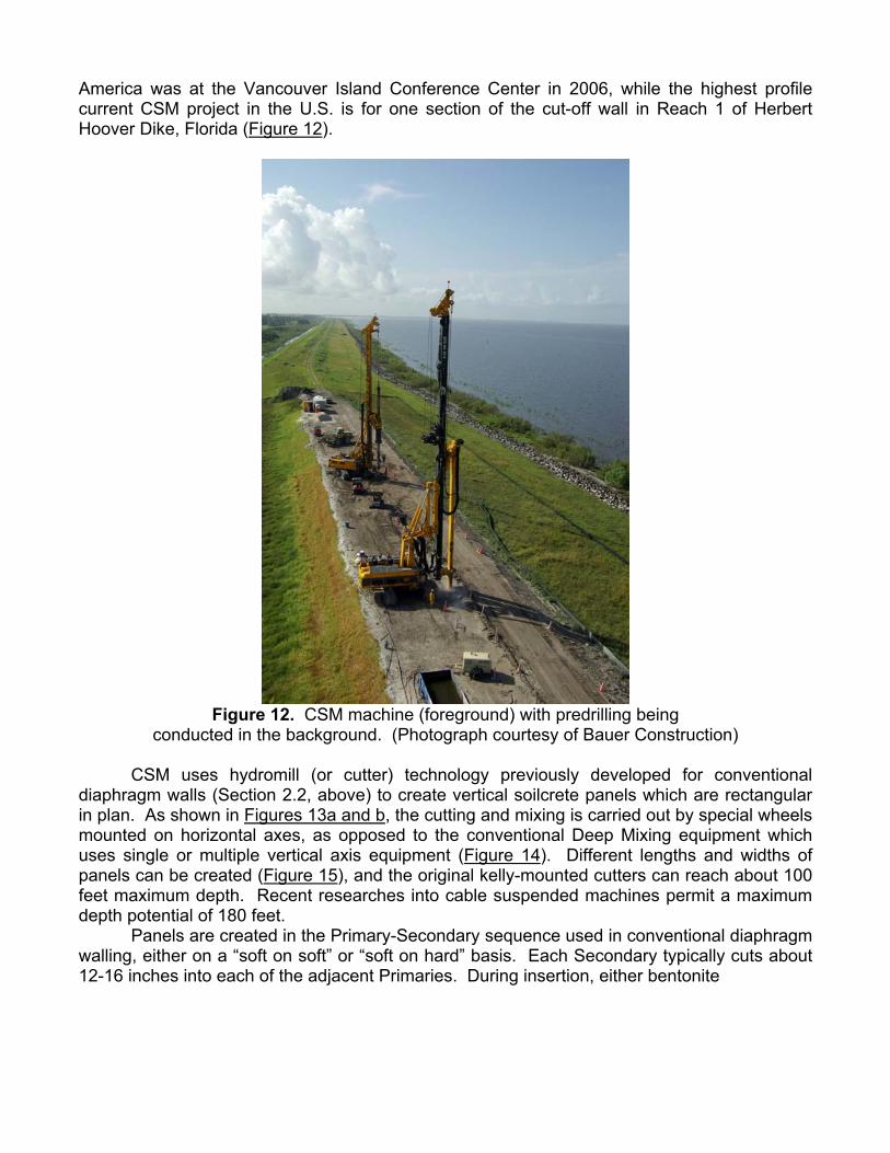
America was at the Vancouver Island Conference Center in 2006, while the highest profile current CSM project in the U.S. is for one section of the cut-off wall in Reach 1 of Herbert Hoover Dike, Florida (Figure 12).
Figure 12. CSM machine (foreground) with predrilling being
conducted in the background. (Photograph courtesy of Bauer Construction) CSM uses hydromill (or cutter) technology previously developed for conventional diaphragm walls (Section 2.2, above) to create vertical soilcrete panels which are rectangular in plan. As shown in Figures 13a and b, the cutting and mixing is carried out by special wheels mounted on horizontal axes, as opposed to the conventional Deep Mixing equipment which uses single or multiple vertical axis equipment (Figure 14). Different lengths and widths of panels can be created (Figure 15), and the original kelly-mounted cutters can reach about 100 feet maximum depth. Recent researches into cable suspended machines permit a maximum depth potential of 180 feet. Panels are created in the Primary-Secondary sequence used in conventional diaphragm walling, either on a “soft on soft” or “soft on hard” basis. Each Secondary typically cuts about 12-16 inches into each of the adjacent Primaries. During insertion, either bentonite
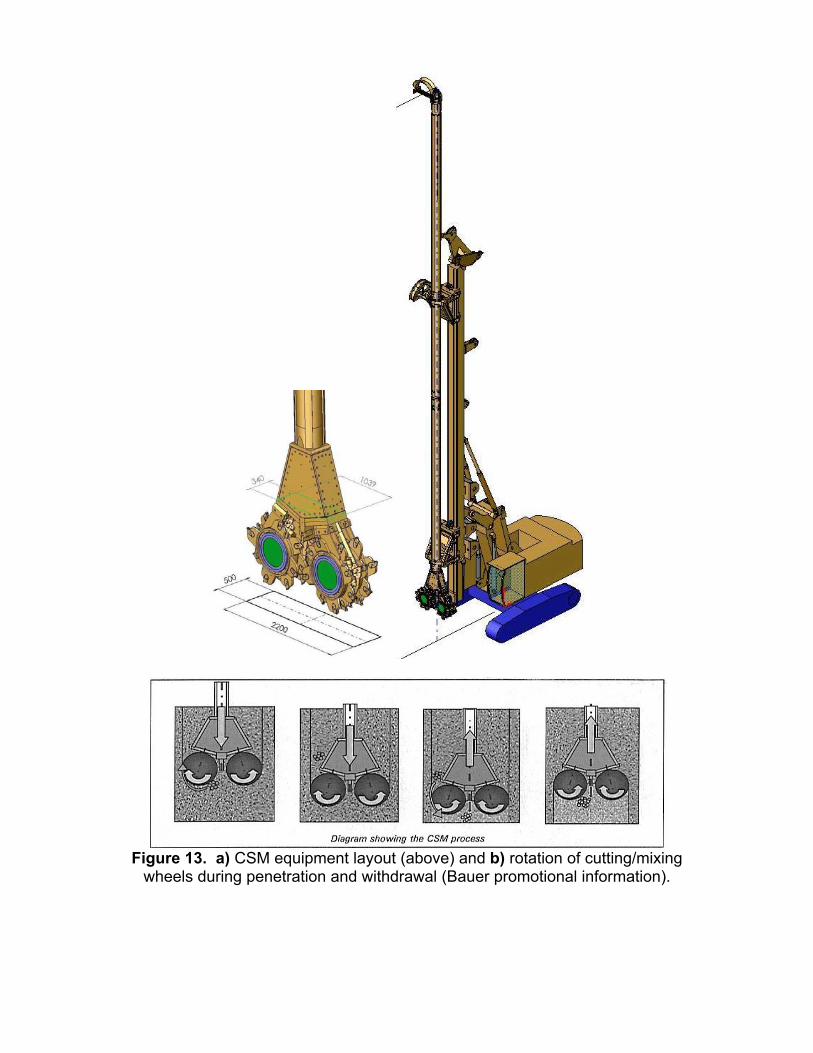
Figure 13. a) CSM equipment layout (above) and b) rotation of cutting/mixing
wheels during penetration and withdrawal (Bauer promotional information).
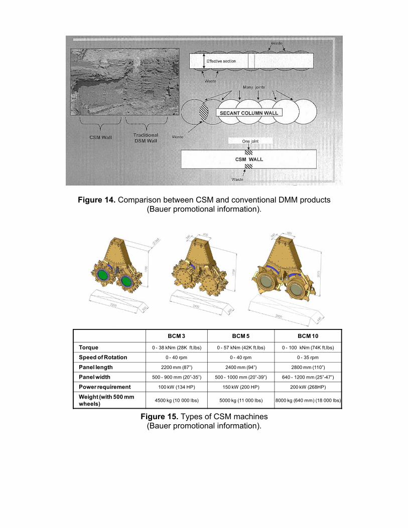
Figure 14. Comparison between CSM and conventional DMM products (Bauer promotional information).
BCM 3 BCM 5 BCM 10
BCM 3 BCM 5 BCM 10
Torque 0 - 38 kNm (28K ft.lbs) 0 - 57 kNm (42K ft.lbs) 0 - 100 kNm (74K ft.lbs)
Speed of Rotation 0 - 40 rpm 0 - 40 rpm 0 - 35 rpm
Panel length 2200 mm (87”) 2400 mm (94”) 2800 mm (110”)
Panel width 500 - 900 mm (20”-35”) 500 - 1000 mm (20”-39”) 640 - 1200 mm (25”-47”)
Power requirement 100 kW (134 HP) 150 kW (200 HP) 200 kW (268HP)
Weight (with 500 mm wheels) 4500 kg (10 000 lbs) 5000 kg (11 000 lbs) 8000 kg (640 mm) (18 000 lbs)
Figure 15. Types of CSM machines
(Bauer promotional information).
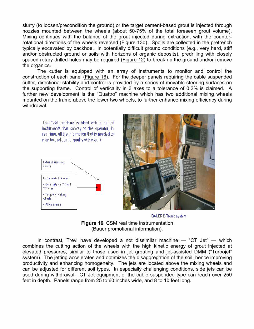
slurry (to loosen/precondition the ground) or the target cement-based grout is injected through nozzles mounted between the wheels (about 50-75% of the total foreseen grout volume). Mixing continues with the balance of the grout injected during extraction, with the counter-rotational directions of the wheels reversed (Figure 13b). Spoils are collected in the pretrench typically excavated by backhoe. In potentially difficult ground conditions (e.g., very hard, stiff and/or obstructed ground or soils with horizons of organic deposits), predrilling with closely spaced rotary drilled holes may be required (Figure 12) to break up the ground and/or remove the organics. The cutter is equipped with an array of instruments to monitor and control the construction of each panel (Figure 16). For the deeper panels requiring the cable suspended cutter, directional stability and control is provided by a series of movable steering surfaces on the supporting frame. Control of verticality in 3 axes to a tolerance of 0.2% is claimed. A further new development is the “Quattro” machine which has two additional mixing wheels mounted on the frame above the lower two wheels, to further enhance mixing efficiency during withdrawal.
Figure 16. CSM real time instrumentation
(Bauer promotional information). In contrast, Trevi have developed a not dissimilar machine — “CT Jet” — which combines the cutting action of the wheels with the high kinetic energy of grout injected at elevated pressures, similar to those used in jet grouting and jet-assisted DMM (“Turbojet” system). The jetting accelerates and optimizes the disaggregation of the soil, hence improving productivity and enhancing homogeneity. The jets are located above the mixing wheels and can be adjusted for different soil types. In especially challenging conditions, side jets can be used during withdrawal. CT Jet equipment of the cable suspended type can reach over 250 feet in depth. Panels range from 25 to 60 inches wide, and 8 to 10 feet long.
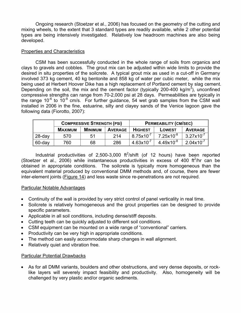
Ongoing research (Stoetzer et al., 2006) has focused on the geometry of the cutting and mixing wheels, to the extent that 3 standard types are readily available, while 2 other potential types are being intensively investigated. Relatively low headroom machines are also being developed. Properties and Characteristics CSM has been successfully conducted in the whole range of soils from organics and clays to gravels and cobbles. The grout mix can be adjusted within wide limits to provide the desired in situ properties of the soilcrete. A typical grout mix as used in a cut-off in Germany involved 373 kg cement, 40 kg bentonite and 858 kg of water per cubic meter, while the mix being used at Herbert Hoover Dike has a high replacement of Portland cement by slag cement. Depending on the soil, the mix and the cement factor (typically 200-400 kg/m3), unconfined compressive strengths can range from 70-2,000 psi at 28 days. Permeabilities are typically in the range 10-6 to 10-8 cm/s. For further guidance, 54 wet grab samples from the CSM wall installed in 2006 in the fine, estuarine, silty and clayey sands of the Venice lagoon gave the following data (Fiorotto, 2007): Industrial productivities of 2,500-3,000 ft2/shift (of 12 hours) have been reported (Stoetzer et al., 2006) while instantaneous productivities in excess of 400 ft2/hr can be obtained in appropriate conditions. The soilcrete is typically more homogeneous than the equivalent material produced by conventional DMM methods and, of course, there are fewer inter-element joints (Figure 14) and less waste since re-penetrations are not required. Particular Notable Advantages • Continuity of the wall is provided by very strict control of panel verticality in real time. • Soilcrete is relatively homogeneous and the grout properties can be designed to provide
specific parameters. • Applicable in all soil conditions, including dense/stiff deposits. • Cutting teeth can be quickly adjusted to different soil conditions. • CSM equipment can be mounted on a wide range of “conventional” carriers. • Productivity can be very high in appropriate conditions. • The method can easily accommodate sharp changes in wall alignment. • Relatively quiet and vibration free. Particular Potential Drawbacks • As for all DMM variants, boulders and other obstructions, and very dense deposits, or rock-
like layers will severely impact feasibility and productivity. Also, homogeneity will be challenged by very plastic and/or organic sediments.
COMPRESSIVE STRENGTH (PSI) PERMEABILITY (CM/SEC) MAXIMUM MINIMUM AVERAGE HIGHEST LOWEST AVERAGE
28-day 570 51 214 8.75x10⁻⁷ 7.25x10⁻⁸ 3.27x10⁻⁷ 60-day 760 68 286 4.63x10⁻⁷ 4.49x10⁻⁸ 2.04x10⁻⁷

• The typical machine requires considerable headroom and access. Unit Costs Mob/demob: $50,000-$100,000 Unit Price: $20-$40/sf Overall Verdict CSM, in its various evolutions, has spread very quickly across several continents over the last 4 years. This is a very telling observation with respect to the attractiveness of the system from both technical and commercial viewpoints. Of particular attraction is CSM’s facility to be operated from standard base machines, and the high level of understanding of the relationship between cutting and mixing wheel design, in situ product quality, and productivity. However, given the fundamentals of its cost base, it will not be competitive in situations where low technology approaches can be used.
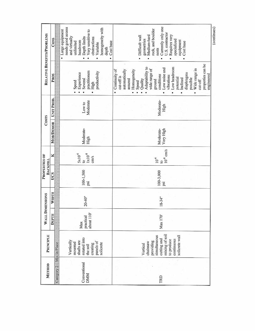
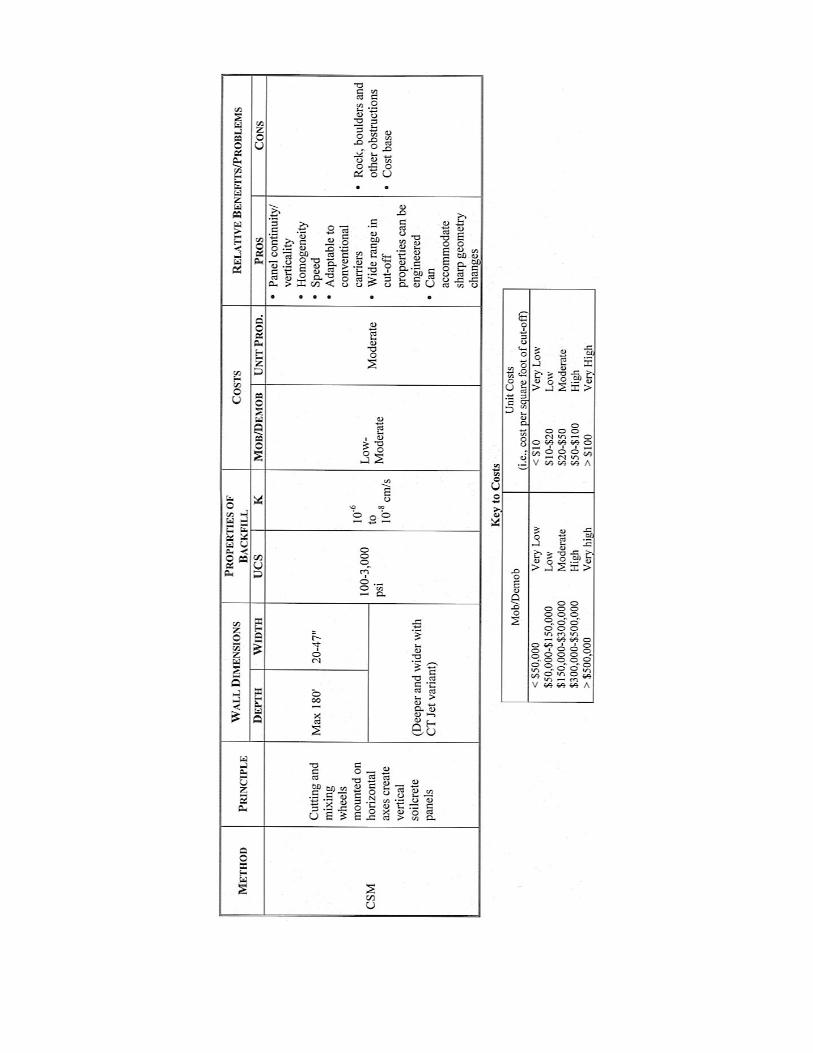
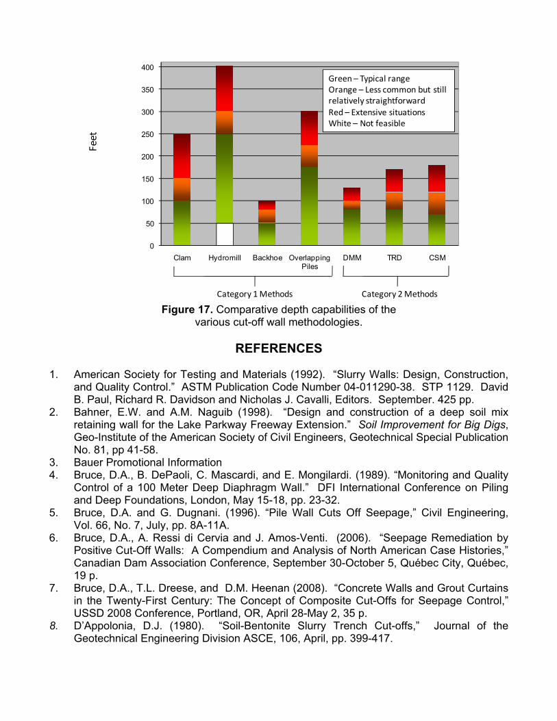
OVERVIEW Table 2 summarizes the salient details of the various technologies reviewed in this paper. Figure 17 provides a comparison of the depth capabilities of the different methods. The author hopes that this paper, and the reference list it contains, will be of practical use to colleagues involved in all aspects of levee remediation with cut-offs.

Tabl
e 2.
Sum
mar
y of
Cha
ract
eris
tics
of V
ario
us C
ut-O
ff W
all M
etho
dolo
gies
.
0
50
100
150
200
250
300
350
400
Clam Hydromill Backhoe Overlapping Piles
DMM TRD CSM
Category 1 Methods Category 2 Methods
Feet
Green – Typical rangeOrange – Less common but still relatively straightforwardRed – Extensive situationsWhite – Not feasible
Figure 17. Comparative depth capabilities of the
various cut-off wall methodologies.
REFERENCES 1. American Society for Testing and Materials (1992). “Slurry Walls: Design, Construction,
and Quality Control.” ASTM Publication Code Number 04-011290-38. STP 1129. David B. Paul, Richard R. Davidson and Nicholas J. Cavalli, Editors. September. 425 pp.
2. Bahner, E.W. and A.M. Naguib (1998). “Design and construction of a deep soil mix retaining wall for the Lake Parkway Freeway Extension.” Soil Improvement for Big Digs, Geo-Institute of the American Society of Civil Engineers, Geotechnical Special Publication No. 81, pp 41-58.
3. Bauer Promotional Information 4. Bruce, D.A., B. DePaoli, C. Mascardi, and E. Mongilardi. (1989). “Monitoring and Quality
Control of a 100 Meter Deep Diaphragm Wall.” DFI International Conference on Piling and Deep Foundations, London, May 15-18, pp. 23-32.
5. Bruce, D.A. and G. Dugnani. (1996). “Pile Wall Cuts Off Seepage,” Civil Engineering, Vol. 66, No. 7, July, pp. 8A-11A.
6. Bruce, D.A., A. Ressi di Cervia and J. Amos-Venti. (2006). “Seepage Remediation by Positive Cut-Off Walls: A Compendium and Analysis of North American Case Histories,” Canadian Dam Association Conference, September 30-October 5, Québec City, Québec, 19 p.
7. Bruce, D.A., T.L. Dreese, and D.M. Heenan (2008). “Concrete Walls and Grout Curtains in the Twenty-First Century: The Concept of Composite Cut-Offs for Seepage Control,” USSD 2008 Conference, Portland, OR, April 28-May 2, 35 p.
8. D’Appolonia, D.J. (1980). “Soil-Bentonite Slurry Trench Cut-offs,” Journal of the Geotechnical Engineering Division ASCE, 106, April, pp. 399-417.
9. Davidson, R.R., G. Dennis, B. Findlay and R.B. Robertson (1992). “Design and Construction of a Plastic Concrete Cut-off Wall for the Island Copper Mine.” Slurry Walls: Design, Construction, and Quality Control. ASTM Publication Code Number 04-011290-38. STP 1129. David B. Paul, Richard R. Davidson and Nicholas J. Cavalli, Editors. September. pp. 271-288.
10. Dinneen, E.A., and M. Sheskier. (1997). “Design of Soil-Cement-Bentonite Cut-off Wall for Twin Buttes Dam,” Proceedings of USCOLD Annual Meeting, San Diego, California, April 7-11, pp. 197-211.
11. Federal Highway Administration. (2000). “An Introduction to the Deep Mixing Method as Used in Geotechnical Applications.” Prepared by Geosystems, L.P., Document No. FHWA-RD-99-138, March, 143 p.
12. Federal Highway Administration. (2001). “An Introduction to the Deep Mixing Method as Used in Geotechnical Applications: Verification and Properties of Treated Soil.” Prepared by Geosystems, L.P., Document No. FHWA-RD-99-167, October, 455 p.
13. Fiorotto, R. (2007). Personal Communication. 14. Fisher, M.J., K.B. Andromalos, and D.N. Johnson. (2005). “Construction of a Self-
Hardening Slurry Cut-off Wall at Taylorsville Dam, OH,” United States Society on Dams, 25th Annual Conference, Salt Lake City, UT, June 6-10, pp. 105-112.
15. Gillon, M., and D.A. Bruce. (2003). “High Pressure Seepage at Arapuni Dam, New Zealand: A Case History of Monitoring, Exploration and Remediation.” United States Society on Dams, San Diego, CA, June 24-28, 10 p.
16. Gularte, F, J. Barneich, J. Burton, E. Fordham, D. Watt, T. Johnson and J. Weeks. (2007). “First Use of TRD Construction Technique for Soil Mix Cut-off Wall Construction in the United Stated,” GeoDenver, Denver, CO, February 18-21, 12 p.
17. Hillis, R.M. and H.W. Van Aller. (1992). “Cement-Bentonite Cut-off Wall Remediation of Small Earthen Dam,” Association of State Dam Safety Officials, 9th Annual Conference, Baltimore, MD, September 13-26, pp. 103-109.
18. Khoury, M.A., A.L. Harris, Jr., and P. Dutko. (1989). “Construction of a Cement-Bentonite Cut-off Wall to Control Seepage at the Prospertown Lake Dam”, Association of State Dam Safety Officials, 6th Annual Conference, Albuquerque, NM, October 1-5, 6 pp.
19. Millet, R.A., J-Y Perez and R.R. Davidson. (1992). “USA Practice Slurry Wall Specifications 10 Years Later,” Slurry Walls: Design, Construction, and Quality Control. ASTM Publication Code Number 04-011290-38. STP 1129. David B. Paul, Richard R. Davidson and Nicholas J. Cavalli, Editors. September. pp. 42-66.
20. Ryan, C.R. and S.R. Day. (2003). “Soil-Bentonite Slurry Wall Specifications,” Pan American Conference on Soils Mechanics & Geotechnical Engineering, Geo-Institute and MIT, Cambridge, MA, June, 8 p.
21. Soletanche Promotional Information 22. Stoetzer, E., F.-W. Gerressen, and M. Schoepf. (2006). "CSM Cutter Soil Mixing - A New
Technique for the Construction of Subterranean Walls, Initial Experiences Gained on Completed Projects," 10th International Conference on Piling and Deep Foundations, Amsterdam, May 31-June 2, 6 p.
23. TRD Promotional Information 24. Trevi Promotional Information 25. Xanthakos, P.P. (1979). “Slurry Walls.” McGraw Hill Book Company, ISBN 0-07-072215-
3, 622 p. 26. Yang, D.S. (1997). “Deep Mixing,” Ground Improvement Ground Reinforcement and
Ground Treatment Developments 1987-1997, Section 2.5, G.S.P. 69, pp 130-150.