Embed Size (px)
Citation preview

Seepage Control Upgrade for Ruskin Dam Right Abutment
Li Yan and Nathan SweeneyBC Hydro
Vancouver Geotechnical Society21 October 2015

Presentation Outline1. Description of the site2. Dam safety issues3. Design and analysis4. Early contractor involvement5. Construction
2

Stave Lake
Ruskin Dam
Hayward Lake
Fraser RiverDistrict of Mission
Stave Falls Dam
Stave River
Project Location
Located in southwest British Columbia, Canada Ruskin Dam is about 50 km east of Vancouver Dam impounds Hayward Lake
3

Concrete dam and spillway
Top of concrete slab cut-off system
Hayward Lake
Stave River
Right Abutment
General Arrangement
Power intakes
Drainage adit
4

Ruskin Dam and Generating Station
5
Dam and generating station constructed between 1929-1931
Generating station nameplate capacity is 105.6 MW
Concrete dam is 113 m long and 59 m high concrete gravity structure founded predominantly on bedrock
Sloping concrete slab cut-off wall system extends upstream of the dam on the right abutment
RockfillSand

Ground Settlement Beneath Slabs
Outline of depression in rockfill
Grout holes
Gallery drain

Dam Safety Issues at Right Abutment
Piping of fine sands into the gallery drain and drainage adit
Collapse/settlement behind the concrete slab
Cracking in the slab caused by settlement
Sinkholes and depressions –upstream and downstream of the dam
Right abutment seepage control concrete slabs do not meet the current seismic design requirements
7
Sei
smic
Nor
mal
Ope
ratio
n
1.8 m

Deficiency Investigations and Site Characterization Site investigations Geologic model Determine engineering
parameters Characterize locations
of loosened sand
8
Becker drilling Mud rotary drilling Diamond drilling, sonic drilling Standard penetration testing
(SPT) Cone penetration testing (CPT) Cross-hole and down-hole
shear wave velocity measurements
Non-intrusive geophysical measurements
Pressuremeter testing

Site Geology
9
1800 m of ice
Unit 5
Unit 1
Unit 3
Unit 6
Unit 2
Unit 4

Site Geology – Quadra Sands
Pro-glacial (outwash) deposited during the Fraser Glaciation
Very dense (many (N1)60 > 100 blows/ft)
Thickness of 15 to 20 m below dam Susceptible to seepage-caused
erosion and piping
Quadra Sand exposed on slope
Concrete Dam
10

Quadra Sand
11
24" 12"8"6" 3" 1½" 3/4" 3/8" #4 #10 #20 #40#60#100#200
0
10
20
30
40
50
60
70
80
90
100
0.00010.0010.010.11101001000
Perc
ent P
assi
ng
Particle Size (mm)
10
15
20
25
30
35
40
45
500 10 20 30 40 50 60 70 80 90 100
Elev
atio
n (m
)
(N1)60 (blows/ft)
Potentially disturbed

12

Key Design Considerations
Build new seepage cut-off system to withstand MDE Need to cut-off the different soil units in the abutment Key cut-off into bedrock Set-back distance from the edge of the slope Dimension and material of cut-off wall (length and
width) Connection of cut-off system to concrete dam Dam safety risks during construction (disturbed
ground and reservoir operation)
13
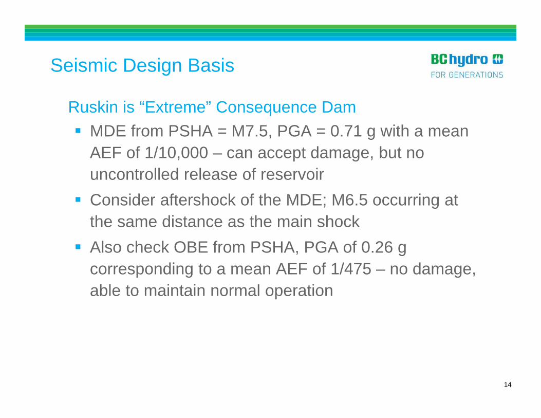
Seismic Design Basis
Ruskin is “Extreme” Consequence Dam MDE from PSHA = M7.5, PGA = 0.71 g with a mean
AEF of 1/10,000 – can accept damage, but no uncontrolled release of reservoir
Consider aftershock of the MDE; M6.5 occurring at the same distance as the main shock
Also check OBE from PSHA, PGA of 0.26 g corresponding to a mean AEF of 1/475 – no damage, able to maintain normal operation
14

Seismic Design and Performance Criteria
Upstream Cut-off Wall (slurry panel) Seepage barrier without existing concrete slabs Flexible to accommodate possible seismic ground
movements near right abutment slope Sufficient length to control the hydraulic gradients to
be less than the current values Post MDE damage (or cracking) is acceptable,
provided any areas of localized shear is less than 50% of the wall width, and post earthquake heads not exceed the top of D/S training wall and filter blanket, and flows not exceed the capacity of the filter blanket and drainage system
15

Seismic Design and Performance Criteria
Cut-off Tie-in to Concrete Dam shall be a flexible structure, capable of
accommodating ground deformations, and concentrated lateral displacements of a minimum of 50 mm without cracking under the MDE loading
shall be robust, with multiple lines of defense shall form an integral connection to the upstream
cutoff wall and concrete dam such that a continuous, watertight barrier is formed, and shall be keyed into bedrock to form a watertight barrier.
16

Seismic Design and Performance Criteria
Downstream Seepage Training Wall Connected to U/S cut-off wall to form a barrier to keep
the D/S slope of the concrete dam from becoming saturated during both normal operation and post earthquake
Has to be flexible to accommodate possible seismic ground movements near right abutment slope
Sufficient length to divert any seepage from hillslope and/or reservoir to D/S filter blanket to keep the area dry
17

Deformation Modeling of Cut-off Wall
~21 m

19
New cutoff wall
FLAC Check – Displacement
FLAC (Version 6.00)
LEGEND
2-Sep-09 20:01 step 4376547Dynamic Time 5.0003E+01 -5.501E+00 <x< 1.445E+02 -2.800E+01 <y< 1.220E+02
X-displacement contours -1.50E+00 -1.25E+00 -1.00E+00 -7.50E-01 -5.00E-01 -2.50E-01 0.00E+00
Contour interval= 2.50E-01Boundary plot
0 2E 1
-0.100
0.100
0.300
0.500
0.700
0.900
1.100
0.100 0.300 0.500 0.700 0.900 1.100 1.300(*10 2̂)
New cutoff wall

Apparent shear strain at 20 m from slab (VERSAT2D_c2b vs. FLAC results)
20
25
30
35
40
45
50
55
0.0 5.0 10.0 15.0 20.0 25.0 30.0
shear strain (%)
Elev
atio
n (m
)
VERSAT2D -fms,low dampingVERSAT2D -fms,high dampingFLAC - HystereticFLAC - MohrCoulomb
Horizontal displacements at 20 m from slab (C2b_lowerbound soil strength)
20
25
30
35
40
45
50
55
-0.7 0.0x-displacement (m)
Elev
atio
n (m
)
C2b_bld
C2b_cpm
C2b_day
C2b_gaz
C2b_grn
C2b_izt
C2b_tar
VERSAT2D -fms,low dampingVERSAT2D -fms,high dampingFLAC - HystereticFLAC -Mohr_Coulomb
Note: C2b is the base case presented in 2008 Report No. E652
FLAC vs. VERSAT

Selection of Material Properties
• Results of the deformation analyses used to select the properties of plastic concrete
• Maximum shear strain of 15%• Maximum shear strength of 0.75 MPa (UCS of 1.5 MPa)• Minimum of 200 kPa at 7 days

22
Seepage Modeling – 3D MODFLOW
The new upstream cutoff wall should have the similar length as the existing slabs to minimize increases of hydraulic gradients in the right abutment after failure of the existing slabs

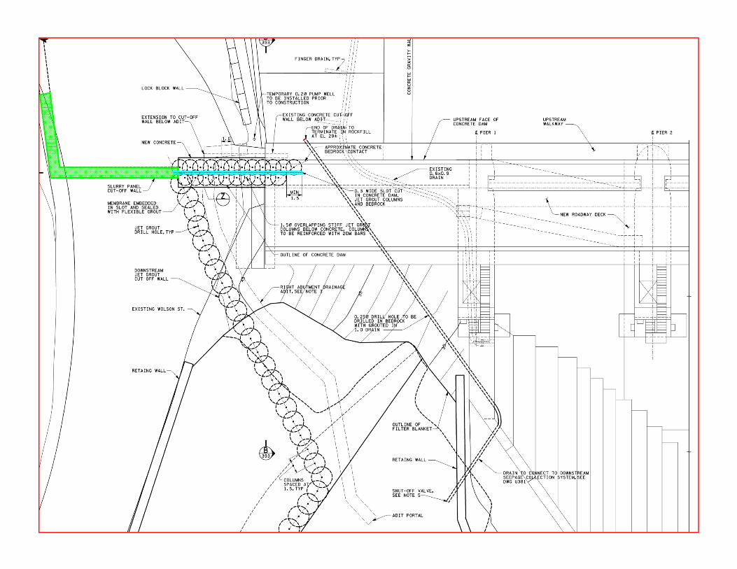
Cut-off Wall Tie-in to Concrete Dam
23
Challenges: Most critical component of the
right abutment upgrade Complicated geometry – sloping
concrete placed on excavated Quadra Sand
Potential for differential deformations between the concrete dam and foundation soils
Close distance to rockfill beneath concrete slabs

Cut-off Wall Tie-in to Concrete Dam
Base Design Strengthen soils beneath the abutment end of concrete
dam by two rows of jet grout (minimum UCS of 6MPa) Cut a slot in concrete dam and jet grout columns Install geomembrane surrounded by cement-bentonite
grout capable of withstanding 50 mm of concentrated deformation
Constructability input required
24

Cutoff Wall Tie-in to Concrete Dam
Extent of concrete
rockfill
loose fill

Slot Stability during Construction

High risk project combined with specialized work components good candidate for Early Contractor Involvement (ECI)
BC Hydro’s version of ECI: Start with conceptual design and performance requirements Develop multiple detailed designs with proponents in parallel Collaborate with proponents in an open environment Start with a target price, end with firm unit pricing; maintain cost
competition throughout the process Transfer knowledge about the site and potential risks (especially
dam safety risks) Develop safe and effective methodologies
ECI Process

Request for proposal Conceptual design provided, site visit
Three proposals received Evaluated based on previous experience on similar projects
and proposed methodology
Two contracts awarded for pre-construction ECI $100,000 paid to each proponent
Selection of a contractor for construction (including field trials)
ECI Process

ECI Process
RFP
Stage 1 (35%)
Stage 2 (65%)
Stage 3 (95%)
Conceptual Design
Selection of contractor for
final clarification
Signed contract
Selection of 2 proponents
Evaluation and
feedback
Evaluation and
feedback
Final Evaluation
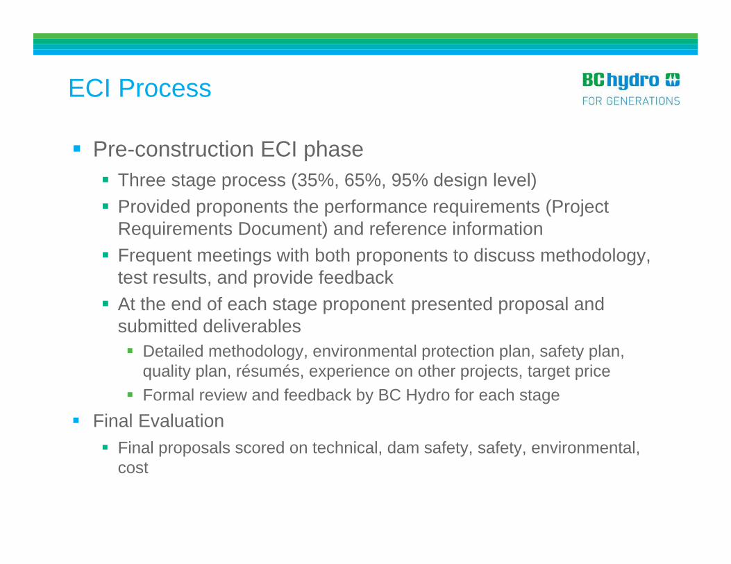
Pre-construction ECI phase Three stage process (35%, 65%, 95% design level) Provided proponents the performance requirements (Project
Requirements Document) and reference information Frequent meetings with both proponents to discuss methodology,
test results, and provide feedback At the end of each stage proponent presented proposal and
submitted deliverables Detailed methodology, environmental protection plan, safety plan,
quality plan, résumés, experience on other projects, target price Formal review and feedback by BC Hydro for each stage
Final Evaluation Final proposals scored on technical, dam safety, safety, environmental,
cost
ECI Process

BC Hydro provided the proponents with a Dam Safety Management plan
Dam safety workshops held with both proponents Options developed to mitigate dam safety risks during
construction Develop monitoring and mitigation plans Contractor’s dam safety management plan New and existing instrumentation Real-time monitoring of construction instrument data and
instrument data by Contractor and BC Hydro Identify high risk work requiring reservoir drawdown
Addressing Dam Safety Risks

Transition to Contract
Final 95% submission included provision for contractor to state exceptions to BC Hydro’s Terms and Conditions Exceptions allowed for appropriate transfer of risk during
negotiations Contract released in 2 stages: Site investigations and field trials Permanent works released upon completion of first stage
Contract allowed for re-pricing of the permanent work based on the results of the first stage Contractor to understand the site and take ownership for the
site conditions Provided confidence in the design and methodology before
the permanent works released

Innovation from ECI• Bitumen based material for slot backfill
• Attractive as one material instead of two• Little precedent for this material and construction• BC Hydro accepted proposal, but required further material testing
and field demonstration
• Realignment of training wall and change from jet grouting to slurry panel plastic concrete wall
Verification of training wall realignment
Jet Grouted Wall
Plastic Concrete Wall

Cutoff Wall and Training Wall
Summary: No of panels: 58 Panel dimensions: 1 m by 2.8 m Maximum panel depth: ~35 m Minimum 0.5 m embedment into bedrock Panel overlap: 300 mm
Quality control/assurance: Cutter response, examination of cuttings
to determine bedrock Mix design trials, sampling and testing of
plastic concrete, in-situ hydraulic conductivity testing
Real-time alignment information, KODEN
35
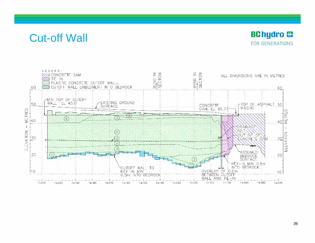
Cut-off Wall
36

Cut-off Wall and Training Wall
37

Plastic Concrete – Triaxial Test
38

Jet Grouting – Dam Safety Risks
High pressure (nozzle at 40 MPa) and high flow (370 lpm) operation – need to minimize dam safety risks Reservoir drawdown for risk
mitigation No air in Type 1 columns Real-time monitoring of pore-
water pressures (1 reading per second)
Jet grouting in voids or loose sand Must maintain reflow at all
times39
Type 1 Columns
Type 3 Columns

Field trial required to demonstrate achievable diameters Ensure that the jet grouting could be completed safely, without
significant dam safety risks
Jet Grouting Field Trial
Type 1 Column (single fluid)Diameter: 1.5 to 2.0 m
Type 3 Column (double fluid)Diameter: 2.0 to 2.5 m
40

Pore Pressure Responses
41
Pore water pressures monitored at 1 to 2 second frequency
Piezometers monitored at a range distances during field trial to determine expected response
Typical piezometric response plotted with location of jet grout monitor
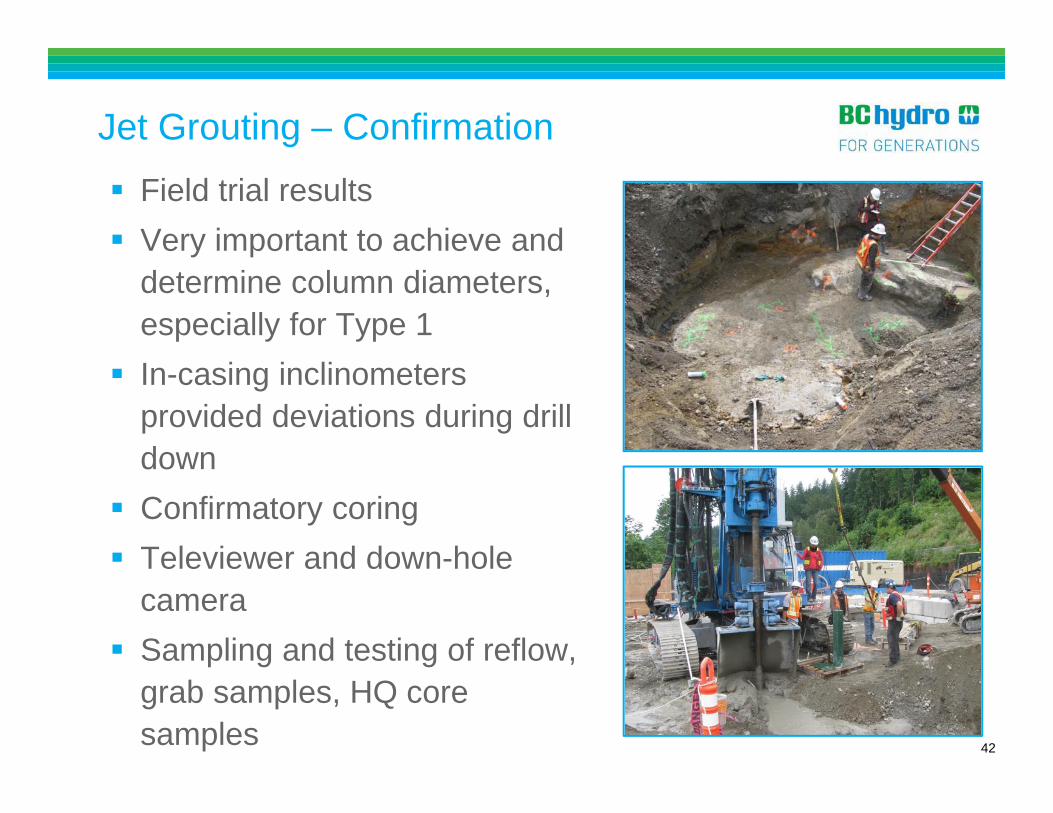
Jet Grouting – Confirmation
42
Field trial results Very important to achieve and
determine column diameters, especially for Type 1
In-casing inclinometers provided deviations during drill down
Confirmatory coring Televiewer and down-hole
camera Sampling and testing of reflow,
grab samples, HQ core samples
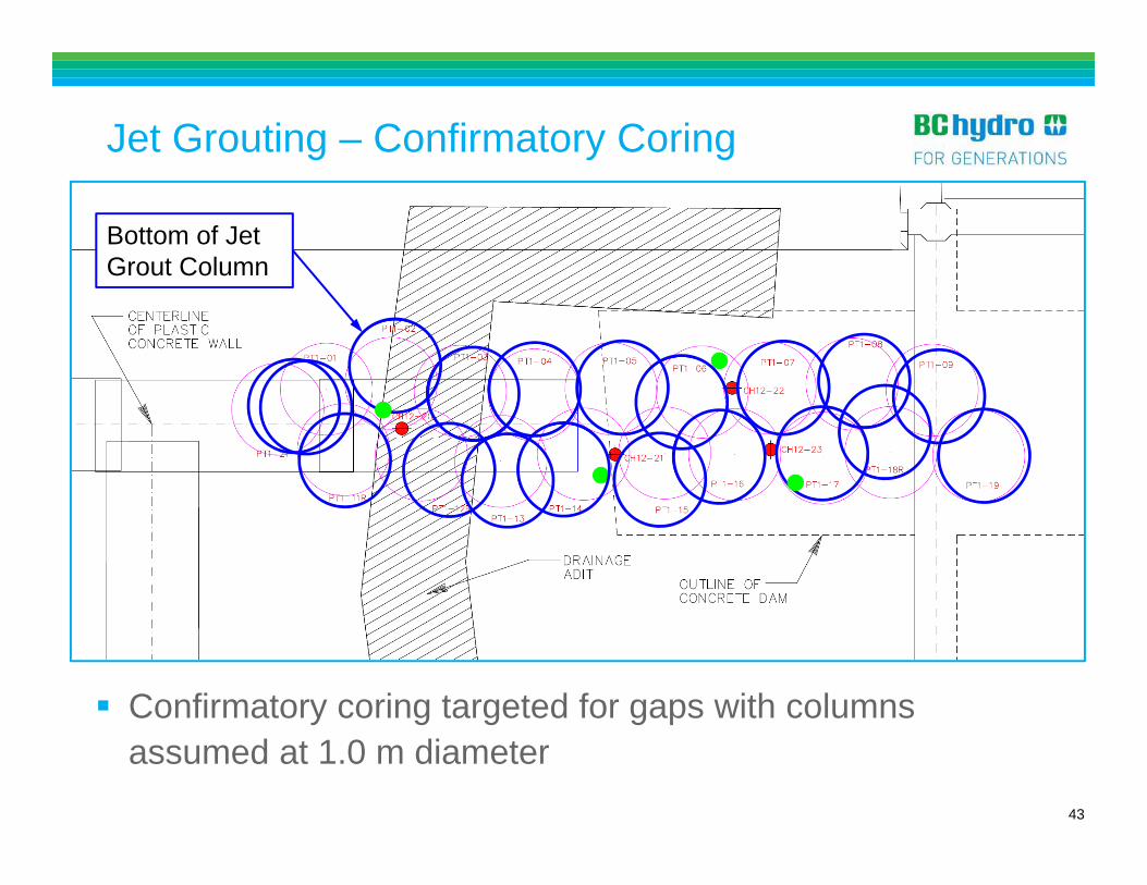
Jet Grouting – Confirmatory Coring
Confirmatory coring targeted for gaps with columns assumed at 1.0 m diameter
Bottom of Jet Grout Column
43

Concrete from Dam
Bedrock
Jet Grouting – Confirmation
HQ Core from Type 1 Columns Televiewer in Type 1 Columns
44

Jet Grouting – UCS Test Results
45

Methodology for Slot Construction
1.5 m
20-27 m
NQ Coring
12” Tricone with stinger
12” DHH or tricone with guide system
ConcreteDam
Soilcrete
20 in
12” Down hole hammer with stinger
12” Coring with stinger

Methodology for Slot Construction
20-27 m
NQ Coring
12” Down hole hammer with stinger
12” Coring with stinger
12” Tricone with stinger
12” DHH or tricone with guide system
ConcreteDam
Soilcrete
1.5 m

ConcreteDam
Methodology for Slot Construction
20-27 m
NQ Coring
12” Tricone with stinger
12” DHH or tricone with guide system
Soilcrete
1.5 m
12” Down hole hammer with stinger
12” Coring with stinger

Tie-in – Slot Construction
Concrete
Soilcrete
49
Tie-in Slot Backfill Material
50
Required a highly flexible material to accommodate differential deformation
BC Hydro prepared base design consisting of a geomembrane and flexible grout Contractor proposed an asphalt based product during ECI
process Very little precedent with asphalt-based cut-offs Some case histories in Japan and Upper Stillwater Dam Required extensive product development and laboratory
and field testing

Construction Field Trials
51
Field trials carried out to understand material behaviour Mastic placed at different temperature into wood
formed slots Establish flowability and temperature limits
Field trial carried out in field trial slot to test proposed construction methodology Only one shot!

Mastic Field Trials
52

Mastic Placement Needed to keep the mastic hot for it to be flowable at
point of discharge Minimum of ~120°C in the mastic at the bottom of the pipe Temperature of mastic at start of pour ranged from about
137°C to 148°C Water in slot required placement of mastic by tremie
method Tremie pipe buried at least 0.5 m in mastic at all times No mixing with water in the slot Seal joints in tremie pipes Cap at bottom of tremie pipe Remove water from tremie pipe Double wall tremie pipes used
53

Mastic Placement – Set-up
Hopper above tremie pipe
Steam heating equipment
Vac truck for removal of water from tremie pipe
Mastic delivered in ready mix trucks
Large crane for removal of tremie pipes
Small crane
Inspection Tent
54

Mastic Placement
55
Weir 15
Weir 14
Weir 13
Weir 9
56
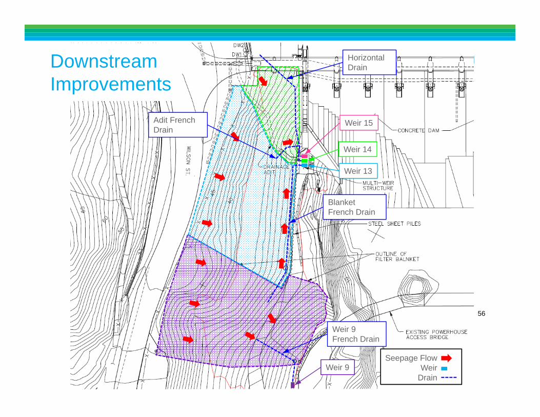
Blanket French Drain
Weir 9 French Drain
Adit French Drain
Horizontal Drain
Seepage FlowWeir
Drain
Downstream Improvements

Weir Flows
Reservoir
Weir 15
57
Weir 13
Construction of new cutoff wall system

Thank-you
58

Acknowledgements
59
BC Hydro Peter Buchanan Steve Garner Jo Ho Maoxin Li Saman Vazinkhoo Guoxi Wu
Consultants Andrew Holmes (seepage
modeling) Ernie Naesgaard (FLAC
analysis) Donald Bruce (project review) Thurber (field inspection)
Contractors Golder Construction (general contractor, cut-off wall, mastic
placement) Malcom Drilling (jet grouting) Foundex (drilling for slot construction, confirmatory coring) Mud Bay (field investigations, well installation)

References
60
France, J.W., Zoccola, M.F., and Yan, L. (2015). The Efficacy of Predrilling in Seepage Barrier Wall Construction. Proceedings of the 2015 United States Society on Dams Annual Meeting and Conference, Louisville, Kentucky.
Sweeney, N. and Yan, L. (2014). Dam Safety Upgrade of the Ruskin Dam Right Abutment. Proceedings of the 2014 Annual Canadian Dam Association Conference, Banff, Alberta
Sweeney, N., Yan, L., and Vazinkhoo, S. (2015). Seepage Control Upgrade for Ruskin Dam Right Abutment. Proceedings of the 2015 United States Society on Dams Annual Meeting and Conference, Louisville, Kentucky.
Wilson, B., Sweeney, N., Atkinson, M., and Diggle, R. (2014). Construction of a very Flexible, Impermeable, Bituminous Membrane Seepage Barrier, to Connect an Existing Concrete Dam to a Newly Constructed Abutment Cut-off Wall. Proceedings of the 39th Annual Conference on Deep Foundations, Atlanta, Georgia.
![Reza 206c@yahoo.com Hadi bay61@ · PDF file[Online]. 8- Ghobadi, M.H., Khanlari, G.R., Jalali, H.D. (2005). Seepage Problems in the Right Abutment of the Shahid](https://img.pdfslide.us/doc/110x75/5ab0c4647f8b9a00728b73f2/reza-206cyahoocom-hadi-bay61-online-http-8-ghobadi-mh-khanlari-gr.jpg)