Embed Size (px)
Citation preview

Send Orders for Reprints to [email protected]
90 The Open Civil Engineering Journal, 2015, 9, 90-97
1874-1495/15 2015 Bentham Open
Open Access
Seepage Analysis of The Structure with Cracks Based on XFEM
Zhong-Yan Huo*,1, Guang-Xuan Qian2 and Dong-Jian Zheng3
1College of Port and Waterway Engineering, Zhejiang Ocean University, Zhoushan, Zhejiang, 316000, China 2Environmental Health Management Office of Dinghai District, Zhoushan, Zhejiang, 316000, China 3College of Water Conservancy and Hydropower Engineering, Hohai University, Nanjing, 210098, China
Abstract: For the difficulty of applying classical fracture criteria to the actual hydraulic engineering and simulating the process of cracking by conditional FEM, the XFEM was introduced in the analysis of the seepage field in hydraulic structures in this paper. Firstly, the enriched forms of nodes are analyzed in the elements intersecting with cracks, and then the enriched functions were built, which could either reflect the features of conductivity matrix within cracks, or satisfy the condition that osmotic pressure is continuous across the crack. Thus, the XFEM approximation form was obtained. Finally, combining the initial conditions and boundary conditions, the discrete equations and workflow of XFEM for solving the seepage field were established. The case study shows that the method is reasonable and reliable.
Keywords: Crack, Seepage filed, XFEM, Enriched function, Hydro-Mechanical, FEM.
1. INTRODUCTION
Due to the characteristics of the structure itself and its construction and operation environment, many hydraulic concrete structures result in cracks. Obviously, the existence of cracks seriously undermines the integrity of a structure, having a significant impact on the structure itself and its morphology, and is also not conducive to operate the structure safely. Therefore, monitoring and analyzing of the deformation of cracks are one of the important contents for safety evaluation of a hydraulic concrete structure. Meanwhile, hydraulic concrete structures are always operated under the effect of Hydro-Mechanical (HM) interaction. In this paper, based on the analysis of the properties of hydraulic concrete structure, analysis and monitoring method of the security status of hydraulic concrete structure crack under the effect of HM interaction is studied by using extended finite element method (XFEM). Infiltration of the reservoir water changes the distribution of the flow field in structures, thereby causing changes in its stress field, displacement field and the crack behavior. Conversely, the seepage boundary condition in cracks changes due to the structural stresses and the geometry fetures of the cracks, thereby affecting the distribution of the permeability and the seepage pressure within the cracks, and changing the seepage field of the crack area in structures. Therefore, in order to analyse the crack behavior of hydrau-lic concrete structures under the interaction of the seepage
*Address correspondence to this author at the Changzhou Road, Zhoushan, Zhejiang, China. Postcard: 316000; Tel: + 86 188570931601; E-mail: [email protected]
and water pressure, the changes of the seepage field, displacement field, and the interaction law between them should be studied at first. Currently, the most versatile and mature means solving the problems related to the fields of seepage and displacement is the FEM. However, for the structures with cracks, as the crack-size changes, it is necessary to mesh and remesh the discontinuity surfaces, thus increasing the computational costs and projection errors associated with conventional finite element methods. Recently, the development of the numerical analysis for solving discrete mechanics, such as XFEM, has facilitated the building of the deformation monitoring methods for those with non-stable cracks. The extended finite element method (XFEM), first introduced by U.S. Northwestern University Study Group headed by Prof.Belytschko [1], provides a convenient and effective way for problems with discontinuities. It models the discontinuity in a displacement field along the crack path, wherever this path may be located without considering the mesh. This flexibility enables the method to simulate crack growth without remeshing. XFEM has been developed rapidly and applied widely in only a few years [2-12]. Thus, the XFEM is an optimum method to study the dynamic expansion of cracks under the interaction of the seepage field and stress field. Considering that there is no precedent in solving seepage problems with this method, in order to analyze the interaction of the two fields under the framework of XFEM, the XFEM approximation and solving method of the seepage field should first be studied. Therefore, the XFEM is introduced to conductseepage analysis on the sructures with cracks. According to the characteristics of seepage field with cracks, the XFEM approximation form

Seepage Analysis of The Structure with Cracks Based on XFEM The Open Civil Engineering Journal, 2015, Volume 9 91
and discrete equations of the seepage field are studied by analyzing the basic theory of seepage and building the enriched functions of crack related elements, and finally, the XFEM for solving the seepage field is established.
2. MATERIALS AND METHODOLOGY
2.1. The Extended Finite Element Discretization
The basic idea of XFEM is to locate the crack path without any respect to the mesh by using some additional function to improve classical FEM. XFEM models the discontinuity in a displacement field along the crack path by incorporating some local enrichment functions into the classical finite element approximation. The displacement field approximation can be expressed as [3]:
( ( )) ( ( ))u u x a x bφ φ= + − + −T N N H H N (1)
Where, N is the array of shape functions; u , a and b represent the vectors of displacement and enriched variables related to nodes. H involves the Heaviside function, and φ is used to model the displacement field around the tip of the discontinuity [13]. According to the westergaard base of asymptotic crack-tip field in the linear elastic fracture mechanics, φ is taken as:
[ ]1 2 3 4= =φ φ φ φ φ
[ ]θ θ θ θrsin rcos rsin sinθ rcos sinθ2 2 2 2 (2)
Asthe displacement field nearing crack-tip for cohesive cracks no longer has the sigularity, according to the asymptotic analysis [13-14] of the mechanical fields in a cohesive zone for a very large structure, φ is taken as:
sin2
r θφ ⎡ ⎤= ⎢ ⎥⎣ ⎦ (3)
Where )(r,θ is the local polar coordinate at the tip.
2.2. Solving the Seepage Field with XFEM
Using XFEM to solve the seepage field in the stuctures with cracks is different to that for discontinuous displacement field. The key to the problem is how to describe the characteristics of conductivity coefficient matrix within cracks effectively and reasonably, and then the enriched functions of crack related elements can be constructed. The functions should either allow the osmotic pressure to be continuous, or make flow balancing at nodes. Because although the distribution of seepage water-head is continuous, the conductivity coefficient matrix within its cracks is different from the rest of the structure, which reflects the impact of cracks on the seepage field. Therefore, the enriched functions of crack related elements should be studied first, and then the XFEM approximation and discrete equations of the seepage filed should be finally built.
2.2.1. Enriched Functions
Similar to the method for describing the displacement field by XFEM, the level set method(LSM) is also used to
simulate the seepage field of structures with cracks, and it is used to select the enriched nodes. There are two forms of enriched node, namely split-element enriched node and tip-element enriched node. Once the mesh generation is the same in the two fields, the enriched nodes are exactly the same, which make the analysis on the interaction of seepage,stress and deformation easier. Despite the above similarities, the enriched functions should be different in seepage field and displacement field. As the water-head, unlike crack deformation, is not discontinuous for the existence of cracks, so the enriched nodes adopted in the seepage field should be separately studied in detail. This is specifically described in two cases as follows.
(1) Enriched Nodes in Split-Element
LSM is adopted to track the crack interface, whose change is expressed as the equation of function ( , )φ x t . The dimension of ( , )φ x t is one dimension higher than that of the crack interface. Mobile interface 2( )tγ ⊂ R could be
assumed as the LSM curve: 2R R R× → , where:
( ){ }2( ) , 0Rγ φ= ∈ : =t x x t (4)
The movement of ( )tγ could be obtained by the evolution equation of φ [15]:
( )0
,0 is givenxF⎧ + ∇ = ⎪
⎨⎪⎩
φ φφt (5)
Where, F is the speed in normal direction of the point( )γ∈x t outside the interface.
LS ϕ is defined as the signed distance function, and LS zero can be described as the crack interface.
ϕ ( )( )
,Xminγ
γγ∈= ± −
tx x xt (6)
When the point x is above the crack ( )tγ , the sign is taken positive; otherwise, it is taken negative.
The water-head enriched function ( )ψ φ in split element should be the function of LS ( , )xφ t . Considering that water-head is continous within the crack, 0 ( ) ( ) Ixψ φ φ φ= = ∑ I
IN is first proposed. However, the
enriched function only exists in the enriched-node domain of support, that is, only the functional values of one-layer elements in both sides of the crack related elements should be calculated, but the function exists in the whole solving domain. In order to meet the above requirements and to improve the convergence rate, some optimization and adjustment should be conducted on this function. The adjustment strategy is as follows: define eM as enriched node set, and define iφ as the value of LS function at each enriched node, and assume ( )i iψ φ φ= . The sets enriched nodes near split elements are defined as { }1 2, , ,p p qM n n nψ + += K , where

92 The Open Civil Engineering Journal, 2015, Volume 9 Huo et al.
the nodes are arranged in ascending order by node value, and its LS value is taken as the initial value. Thus, the optimization algorithm of enriched function of nodes inMψ is as follows:
For J = p+1, q
Building the set { }:J i e i jG nod M Mψ ψ φ= ∈ ∪ < ,
Where the nodes inod and jnod have the same element edge;
( )jψ φ is solved by minimizing the following equation: 2
I J
J I
nod M IJ
mind
ψ φ∈
⎛ ⎞−⎜ ⎟⎝ ⎠
∑ ,where IJd is the distance between node
I and J. The result of solving the problem of the minimum value is expressed as follows:
J
J I Inod M
ψ α φ∈
= ∑ ,2
2
11
K J
II
Knod M
LL
α∈
=∑
(7)
As known from the above derivation, the desired enriched function should be expressed as:
1( ) ( )xψ φ ψ ψ= = ∑I I IIN (8)
Referring to the definition of displacement field enhanced mode ( )( ) ( ) ( )x x xψ ψ= −∑enr
j j jj
u a N , the
enriched function of enriched nodes in seepage field is defined as [15]:
2 ( ) ( ) ( )x xψ ϕ ϕ= −∑ ∑i i i ii i
X N N (9)
One-dimensional schematic of the above enriched functions 0 ( )ψ φ 、 1( )ψ φ and 2 ( )Xψ is as shown in Fig. (1), where the convergence rate of 2 ( )ψ x is highest and close to the optimum convergence rate of the FEM. There is a ridge at the position of crack winthin the two-dimensional schematics of 2 ( )xψ (Fig. (2) and Fig. (3)). The value of function 2 ( )xψ is zero within the elements which do not contain the cracks [14].
Fig. (1). Several choices for the enrichment function.
Fig. (2). Enrichment function 2 ( )xψ .
Fig. (3). Enrichment function 2 ( )xψ .
(2) Enriched Nodes in Tip-element
If the crack terminates within the element, and the above enriched function is used, then the crack tip is treated as extending to the edge of element, and the result is no longer considered to be accurate. While there is a tip enriched function, selecting the analytic solution of asymptotic crack-tip field as enriched function, it could be ensured that the crack terminates exactly within the element. The main items of asymptotic expansion of the water-head and flow velocity are as follows:
2 cos2θ
π⎛ ⎞= − ⎜ ⎟⎝ ⎠
HK rHk
, cos2
2 sin2
θ
θ
⎛ ⎞⎛ ⎞⎜ ⎟⎜ ⎟⎝ ⎠⎜ ⎟= −
⎜ ⎟⎛ ⎞⎜ ⎟⎜ ⎟⎝ ⎠⎝ ⎠
HKvπr
(10)
According to the above expansion items, the second item of the formula (2) should be used as the enriched function of crack tip: cos
2θϕ ⎛ ⎞= ⎜ ⎟⎝ ⎠
r . Since the value of LS at the crack
interface is zero, it has no effect on the situation that crack is set as the boundary. In summary, the XFEM approximation of seepage field can be expressed as follows:
Crack Enriched node
¦ ×2¦ ×0
¦ ×1
Interface
1.5
3
1.5
Enriched node
y
x
Seepage Analysis of The Structure with Cracks Based on XFEM The Open Civil Engineering Journal, 2015, Volume 9 93
( )( )
*I
k
( ) ( ) ( ) e
( ) ( )
hi i j j j
i j J
k kk K
H N H N
N f
φ φ
ϕ ϕ∈ ∈
∈
= + − +
−
∑ ∑
∑
x x x
x x (11)
Where, x is the coordinate vector of point, ( )iN x , ( )jN x and ( )xkN are the shape functions of the conventional
FEM. iH is the conventional water-head of nodes. je and
kf are the water-head enriched DOFs of split-element and tip-element, respectively. ( )xφ and ( )xϕ are
correspondingly the enriched functions, while φj and ϕk are
the values of the two kinds of node. I is the set of all the nodes. *J is the node-set of all elements intersected by crack. K is the node set of tip elements. As shown in formula (11), if there is no crack intersecting the element, then the first item at the right of the equation should be taken as the seepage field of the element. While in the split element, the first two items at the right of the equation should be taken. If the crack terminates within the elements, then the whole three items at the right of the equation should be used. In theplane, each nodes in split element and tip element have two DOFs, while other nodes have one DOF [15].
2.2.2. XFEM Discrete Equation of Seepage Field
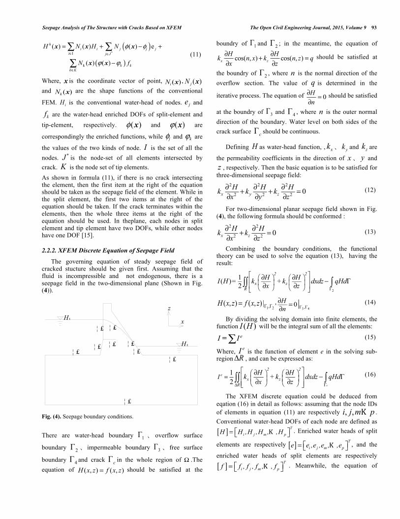
The governing equation of steady seepage field of cracked stucture should be given first. Assuming that the fluid is incompressible and not endogenous, there is a seepage field in the two-dimensional plane (Shown in Fig. (4)).
Fig. (4). Seepage boundary conditions.
There are water-head boundary 1Γ 、 overflow surface
boundary 2Γ 、 impermeable boundary 3Γ 、 free surface
boundary 4Γ and crack Γc in the whole region of Ω .The equation of ( , ) ( , )H x z f x z= should be satisfied at the
boundry of 1Γ and 2Γ ; in the meantime, the equation of
cos( , ) cos( , )x zH Hk n x k n z qx z
∂ ∂+ =∂ ∂
should be satisfied at
the boundry of 2Γ , where n is the normal direction of the overflow section. The value of q is determined in the
iterative process. The equation of 0∂ =∂Hn
should be satisfied
at the boundry of 3Γ and 4Γ , where n is the outer normal direction of the boundary. Water level on both sides of the crack surface Γc should be continuous.
Defining H as water-head function, , xk 、 yk and zk are
the permeability coefficients in the direction of x、 y and z , respectively. Then the basic equation is to be satisfied for three-dimensional seepage field:
2 2 2
2 2 2 0x y zH H Hk k kx y z
∂ ∂ ∂+ + =∂ ∂ ∂
(12)
For two-dimensional planar seepage field shown in Fig. (4), the following formula should be conformed :
2 2
2 2 0∂ ∂+ =∂ ∂x zH Hk kx z
(13)
Combining the boundary conditions, the functional theory can be used to solve the equation (13), having the result:
2Γ
1( ) Γ2
2 2
x zR
H HI H = k +k dxdz qHdx z
⎡ ⎤⎛ ⎞ ⎛ ⎞⎢ ⎥⎜ ⎟ ⎜ ⎟⎢ ⎥⎝ ⎠ ⎝ ⎠⎣ ⎦
∂ ∂ −∂ ∂∫∫ ∫
1 2Γ ,Γ( , ) ( , ) |H x z f x z= ,3 4Γ ,Γ0|H
n∂ =∂
(14)
By dividing the solving domain into finite elements, the function ( )I H will be the integral sum of all the elements:
eI I∑= (15)
Where, eI is the function of element e in the solving sub-region RΔ , and can be expressed as:
1 Γ2
e
e2 2
x zR
I H Hk +k dxdz qHdx zΔ Γ
⎡ ⎤⎛ ⎞ ⎛ ⎞= ⎢ ⎥⎜ ⎟ ⎜ ⎟⎝ ⎠ ⎝ ⎠⎢ ⎥⎣ ⎦
∂ ∂ −∂ ∂∫∫ ∫ (16)
The XFEM discrete equation could be deduced from eqation (16) in detail as follows: assuming that the node IDs of elements in equation (11) are respectively , ,i j m pK . Conventional water-head DOFs of each node are defined as
[ ] T
i j m pH H ,H ,H , ,H⎡ ⎤= ⎣ ⎦K . Enriched water heads of split
elements are respectively [ ] T
i j m pe e ,e ,e , ,e⎡ ⎤= ⎣ ⎦K , and the
enriched water heads of split elements are respectively
[ ] T
i j m pf f , f , f , , f⎡ ⎤= ⎣ ⎦K . Meanwhile, the equation of
¦ £4
¦ £1
¦ £1¦ £1
¦ £c
¦ £1
¦ £2
¦ £3
¦ £1H 2
H 1 x
z

94 The Open Civil Engineering Journal, 2015, Volume 9 Huo et al.
Γ
=∫e
qHdΓ Q should be satisfied, which means that the
nodal flow is equivalent, and is zero in all the internal nodes and boundary nodes carrying no flow. For two-dimensional seepage flow, ( ),eH x z represents the water-head of any
point in the sub-region of elements. Then ( ),eH x z is available by interpolating the water head of each node:
( ),ei i j j m m p pH x z N H N H N H N H= + + +K
i i i j j j m m m p p pN e N e N e N eψ ψ ψ ψ+ + + +K
i i i j j j m m m p p pN f N f N f N fϕ ϕ ϕ ϕ+ + + +K (17)
Where, , , , ,i j m pN N N NK are the conditional shape
functions of element nodes. , , , ,i j m pψ ψ ψ ψK represent the values of enriched functions of the nodes in split elements. And , , , ,ϕ ϕ ϕ ϕi j m pK are the values of enriched functions of the nodes in tip elements.
The integral terms in formula (16) should be differentiated to any DOF while deriving the discrete equations. And the differentiator to iH is taken as an example as follows:
e
x zi i iR
I H H H Hk +k dxdzH x H x z H zΔ
⎡ ⎤∂ ∂ ∂ ∂ ∂ ∂ ∂⎛ ⎞ ⎛ ⎞= ⎢ ⎥⎜ ⎟ ⎜ ⎟∂ ∂ ∂ ∂ ∂ ∂ ∂⎝ ⎠ ⎝ ⎠⎣ ⎦∫∫
Γe i
Hq dHΓ
∂−∂∫ (18)
( ) ( )( ) ( )
( ) ( )( ) ( )
ψ ψψ ψ
ϕ ϕϕ ϕ
∂ ∂∂ ∂∂ = + + + +∂ ∂ ∂ ∂ ∂
∂ ∂∂ ∂+ + + +∂ ∂ ∂ ∂
∂ ∂∂ ∂+ + +∂ ∂ ∂ ∂
j pi mi j m p
j j p pi i m mi j m p
j j p pi i m mi j m p
N NN NH H H H Hx x x x x
N NN Ne e e ex x x x
N NN Nf f f fx x x x
K
K
K
( )
ii
i i
i ii i
i i
NH H NH x x H
NH H Nf x x f
ϕϕ
∂∂ ∂ ∂⎛ ⎞ = =⎜ ⎟∂ ∂ ∂ ∂⎝ ⎠
∂∂ ∂ ∂⎛ ⎞ = =⎜ ⎟∂ ∂ ∂ ∂⎝ ⎠
M M
,
,
(19)
Substituting formula(18) into formula (19):
{ } { } { }{ }
e
i
e e
eTT T Ti
e
i
IH
I Ie
H e f
If
⎧ ⎫∂⎪ ⎪∂⎪ ⎪⎪ ⎪⎪ ⎪∂ ∂⎪ ⎪ =⎨ ⎬∂⎪ ⎪ ⎡ ⎤∂ ⎣ ⎦⎪ ⎪
⎪ ⎪∂⎪ ⎪
⎪ ⎪∂⎩ ⎭
M
M
= { } { } { }{ }⎡ ⎤⎡ ⎤⎣ ⎦ ⎣ ⎦
eTT T Tek H e f − { }eQ =0 (20)
Where { }eQ is the flow matrix of element, and ek⎡ ⎤⎣ ⎦ is the
conduction matrix of element. According to the formula (18), e
ijk and eiQ could be respectively calculated as follows:
⎡ ⎤⎢ ⎥= ⎢ ⎥⎢ ⎥⎣ ⎦
HH He Hfij ij ij
e eH ee efij ij ij ij
fH fe ffij ij ij
h h hk h h h
h h h
,
( ) ΩTrs r s
ij j rs iRh B S B d
Δ= ∫ , ( )r,s= H,e, f (21)
{ } { }ei i i i i iΓQ N N N q dφ
e
Tψ= Γ∫ (22)
Where,
H i ii
N NBx z
∂ ∂⎡ ⎤= ⎢ ⎥∂ ∂⎣ ⎦, ( ) ( )i i i ie
i
N NB
x zψ ψ∂ ∂⎡ ⎤
= ⎢ ⎥∂ ∂⎣ ⎦,
( ) ( )i i i ifi
N NB
x zφ φ∂ ∂⎡ ⎤
= ⎢ ⎥∂ ∂⎣ ⎦,.. represents permeation
coefficient matrix.
There are some descriptions for rsS as follows:
(1) Permeability coefficient matrices in the elements without intersecting with cracks are consistent with that of the conventional FEM. (2) In the elements intersecting with cracks, the permeability coefficient matrices include two parts: permeability coefficient of the element and that of the crack. The former is consistent with that of the conventional FEM, while in the latter condition, the cracks are treated as a medium, and the permeability coefficient is solved by the width of the cracks; and then the permeability coefficient should be converted from the spindle direction within cracks into the global coordinate system.
1
2
xrs l g
z
k 0 k 0S M
0 k 0 k→⎡ ⎤ ⎡ ⎤
= =⎢ ⎥ ⎢ ⎥⎣ ⎦ ⎣ ⎦
, l gM → is the transformation
matrix that converts the local coordinate system into the
global coordinate system. The rsS present in the formula (21) refers to the permeability coefficient within cracks, while r,s represent the enriched DOFs ore f . If any one of the
r,s is taken as the conventional DOF, then the rsS is consistent with that of the continuous part of the structure. Thus, in the elements intersecting with cracks, the influence of crack is maintained within the permeability coefficient matrix. By integrating the results of all the elements, the equations in solving region could be obtained:
{ } { } { }{ } [ ]{ } { } 0TT T T
I k H QH e f
∂ = − =⎡ ⎤∂ ⎣ ⎦
(23)

Seepage Analysis of The Structure with Cracks Based on XFEM The Open Civil Engineering Journal, 2015, Volume 9 95
Where, { }H is the water-head matrix of all the nodes
(including the enriched nodes). [ ]k is the total permeability
coefficient matrix, where the factor ijk could be integrated by
the eijk of each element related to node i . { }Q is the flow
array of nodes, and the water head of any point within elements could be calculated from formula (17).
2.2.3. Solving Steps for Seepage Field by XFEM
Solving seepage problems of free surface section is related to the procession of the elements intersected by the infiltration line. In this study, initial flow method is adopted to determine the position of the free surface, and this constant mesh method is effective to solve the seepage problem of free surface. The basic idea is that the free surface is divided into two sub-domains by the infiltration line, and the two parts have no flow exchange, which could be basically achieved by adjusting the initial flow normal to the free surface [16]. For the initial flow method, the FEM equation [16] of the whole region could be expressed as:
[ ]{ } { } { }0k H Q Q= + (24)
Where, [ ]k and { }Q are respectively the total penetration
matrix and equivalent nodal flow matrix. { }0Q is the nodal flow matrix caused by the increasing initial flow, its expression is:
{ } [ ]( ) [ ][ ] [ ]0 e
Te T e
eQ A B k F B d H
Ω= Ω⋅∑ ∫ (25)
Where, F is a discontinuous function, and the values of F in unsaturated zone and saturated zone are respectively taken as 0 and 1. [ ]eA is the selection matrix for integral assembling. [ ]k and[ ]B have the same means as formula (21).
Combined with the initial flow method, the solving steps for seepage field by XFEM are as follows: (1) Meshing for XFEM, the water head of all nodes is calculated by the formula (17).
(2) At first, according to the relationship between water headh and z , determining the value iF of each node, the value of each Gauss integration point within element could be obtained by:
G i ii
F N F=∑ . Secondly, by the convergence
criteria, it is judged whether the difference { }HΔ between the results of the adjacent two iterations is zero. If it is zero, then computing is stopped, else, the procedure is moved to the next step.
(3) { }0nQ is defined as the increment of water head at the
right of the equation:
[ ]{ } { }0n nk H QΔ = ,{ } { } { }1n n nH H H+Δ = + Δ (26)
(4) After returning to step (2), and keeping the iteration, unit{ }HΔ meets the convergence conditions, and the results of each node are the desired water heads. It is to be noted that
the convergence criterion is: { }max nH εΔ ≤ .
3. RESULTS
A typical sectional view of the non-overflow section of a concrete gravity dam is shown in Fig. (5). Its crest width and height are respectively 10m and 65m. The width and elevation of the dam bottom are 53m and 65m, respectively. The downstream slope is 1:0.7, and the impermeable curtain is below the surface 32m in-depth. The upstream water level is 112m, and the downstream water level is 68.5m. To simplify the analysis, the impact of the dam drainage is not considered here.
Fig. (5). Typical profile of a gravity dam.
The XFEM model of the dam section is built at first, and then the seepage field is calculated under the action of 112 m water level respectively under the conditions that the dam section has upstream horizontal fracture and has no crack. Permeability coefficient of the dam is taken as 8.0×10⁻⁹ m/s, and that of the curtain and foundation are taken as 5.0×10⁻⁸
m/s and 1.5×10⁻⁷ m/s. It is assumed that there is horizontal construction which is 10m in length. The average width and initial permeability coefficient are 0.2mm and 1.0×10⁻³m/s, respectively (referring to the layer value of the RCC dam). XFEM model of the section is totally arranged at 1240 nodes and 1159 elements, and the seepage water level distributions obtained are shown in Fig. (6) and Fig.(7), respectively. As shown in Fig. (6) and Fig. (7), the existence of crack has a great impact on the seepage field near the crack area, and the gradient of the water permeability within the crack is
10.0m
Impervious curtain
53.0m
112.0m
Crack
120.7m
65.0m
85.0m
130.0m
68.5m

96 The Open Civil Engineering Journal, 2015, Volume 9 Huo et al.
small, which is consistent with the actual situation. Thus, the feasibility and correctness of the compiled programs for XFEM solving seepage field have been proved in this study.
CONCLUSION
Based on the study of principles and characteristics of XFEM, the analysis of the seepage field in hydraulic structures was introduced in this paper. At first, the enriched forms of nodes were analyzed in elements intersecting with cracks, and the enriched functions were built, which could either reflect the features of conductivity matrix within cracks, or satisfy the condition that osmotic pressure is continuous across the crack. Thus the XFEM approximation form was obtained. Finally, combining the initial conditions and boundary conditions, the discrete equations and workflow of XFEM for solving the seepage field were established. The case study shows that the method is reasonable and reliable.
The seepage field and displacement field were solved in the unified framework of XFEM, and both the two fields had the same mesh and enriched node set. Thus, at each step of crack propagation, only one-time judgment should be conducted for the enriched nodes. Furthermore, both the
troubles of determining the corresponding relationship of the variables between the two fields, and the coordination problem of different meshes could be avoided in dealing with the coupling problems. The computing efficiency could also be improved. For the hydraulic structures with crack, the XFEM of solving crack propagation problem has great potential. In this paper, only the method of solving seepage field by XFEM is proposed, but how to apply it to the analysis of crack extension needs further study.
CONFLICT OF INTEREST
The authors confirm that this article content has no conflict of interest.
ACKNOWLEDGEMENTS
The Special Fund Support of Open Research Foundation of Chinese Yangtze River Scientific Institute (Grant Nos. CKWV2014215/KY) is gratefully acknowledged.
REFERENCES [1] T. Belytschko, and T. Black, “Elastic crack growth in finite
elements with minimal remeshing”, Int. J. Numer. Meth. Eng., vol. 45, no. 5, pp. 601-620, 1999.
Fig. (6). Distribution of seepage field without cracks (unit: m).
Fig. (7). Distribution of seepage field with a crack (unit : m).
112.0m
68.5m
68.5m
112.0m

Seepage Analysis of The Structure with Cracks Based on XFEM The Open Civil Engineering Journal, 2015, Volume 9 97
[2] T. Belytschko, and D. Organ, “Element-free galerkin methods for dynamic fracture in concrete”, Comp. Meth. Appl. Mech. Eng., vol. 187, no. 3, pp. 385-399, 2000.
[3] M. Stolarska, and D.L. Chopp, “Modelling crack growth by level sets in the extended finite element method”, Int. J. Numer. Meth. Eng., vol. 51, no. 8, pp. 943-960, 2001.
[4] N. Sukumar, and J.H. Prevost, “Modeling quasi-static crack growth with the extended finite element method, Part I: Computer implementation”, Int. J. Solids Struct., vol. 40, no. 26, pp.7513-7537, 2003.
[5] T. Belytschko, and R. Gracie, “On XFEM applications to dislocations and interfaces”, Int. J. Plasticity, vol. 23, no.10, pp.1721-1738, 2007.
[6] J. Dolbow, and I. Harari, “An efficient finite element method for embedded interface problems”, Int. J. Numer. Meth. Eng., vol. 78, no. 2, pp. 229-252, 2009.
[7] Y. J. Xu, and H. Yuan, “On damage accumulations in the cyclic cohesive zone model for XFEM analysis of mixed-mode fatigue crack growth”, Comp. Mat. Sci, vol. 46, no. 3, pp. 579-585, 2009.
[8] J. Shi, and D. Chopp, “Abaqus implementation of extended finite element method using a level set representation for three-dimensional fatigue crack growth and life predictions”, Eng. Fract. Mech., vol. 77, no. 14, pp. 2840-2863, 2010.
[9] N. Moes, and T. Belytschko, “Extended finite element method for cohesive crack growth”, Eng. Fract. Mech., vol. 69, no. 7, pp. 813-833, 2002.
[10] J. F. Unger, S. Eckardt, and C. Konke, “Modeling of cohesive crack growth in concrete structures with the extended finite element method”, Comput. Method Appl. M, vol. 196, no. 41, pp. 4087-4100, 2007.
[11] J. L. Asferg, P. N. Poulsen, and L. O. Nielsen, “A direct XFEM formulation for modeling of cohesive crack growth in concrete” Comput. Concrete, vol. 4, no. 2, pp. 83-100, 2007.
[12] X. J. Fang, F. Jin, and J. T. Wang, “Cohesive crack model based on extended finite element method”, Tsinghua Sci. Technol., vol. 3, pp. 344-347, 2007. (IN CHINESE)
[13] J. Planas, and M. Elices, “Asymptotic analysis of a cohesive crack_1_Theoretical background”, Int. J. Fract., vol. 55, no. 2, pp.153-177, 1992.
[14] J. Planas, and M. Elices, “Asymptotic analysis of a cohesive crack_2_Influence of the softening curve”, Int. J. Fract., vol. 64, no. 3, pp. 221-237, 1993.
[15] N. Sukumar, D. L. Chopp, N. Moes, and T. Belytschko, “Modeling holes and inclusions by level sets in the extended finite-element method”, Comput. Method Appl. M, vol. 190,no. 46-47, pp. 6183-6200, 2001.
[16] Z. Yangsheng. Fluid mechanics of mines and rocks, Beijing: Coal Industry Press, 1994: pp. 125-145. (In Chinese).
Received: September 17, 2014 Revised: December 17, 2014 Accepted: December 23, 2014 © Huo et al.; Licensee Bentham Open.
This is an open access article licensed under the terms of the Creative Commons Attribution Non-Commercial License (http://creativecommons.org/licenses/ by-nc/4.0/) which permits unrestricted, non-commercial use, distribution and reproduction in any medium, provided the work is properly cited.