Embed Size (px)
Citation preview
Hearth & Home Technologies Inc. • Cinch Pipe & Term Caps • 4033-179 Rev E • 06/06 1
Models:Cinch Pipe & Termination Cap System
Installation Instructions
If you need assistance during installation, contact your local dealer or the Technical Services Dept., Hearth & Home Tech-nologies Inc., phone 1-800-927-6841 or 1-888-427-3973.
Note: An arrow (�) found in the text signifi es change in content.
Sharp Edges• Wear protective gloves and safety glasses
during installation.
CAUTION
See the installation instructions included with the appliance for confi guration of vent assem-bly and clearances to pipe.
If DVP-AD adapters are used off the top of the appliance, the termination height will be raised by 2-3/4 in. overall height.
Hearth & Home Technologies disclaims any responsibility for, and the warranty will be voided by, the following actions:
• Installation and use of any damaged vent system component.
• Modifi catoin of the vent system.• Installation other than as instructed by
Hearth & Home Technologies.• Installation and/or use of any component
part not approved by Hearth & Home Technologies.
Any such action may cause a fi re hazard.
WARNING
Do not mix pipe, fittings or joining methods from different manufacturers.
WARNING
Hearth & Home Technologies Inc. • Cinch Pipe & Term Caps • 4033-179 Rev E • 06/062
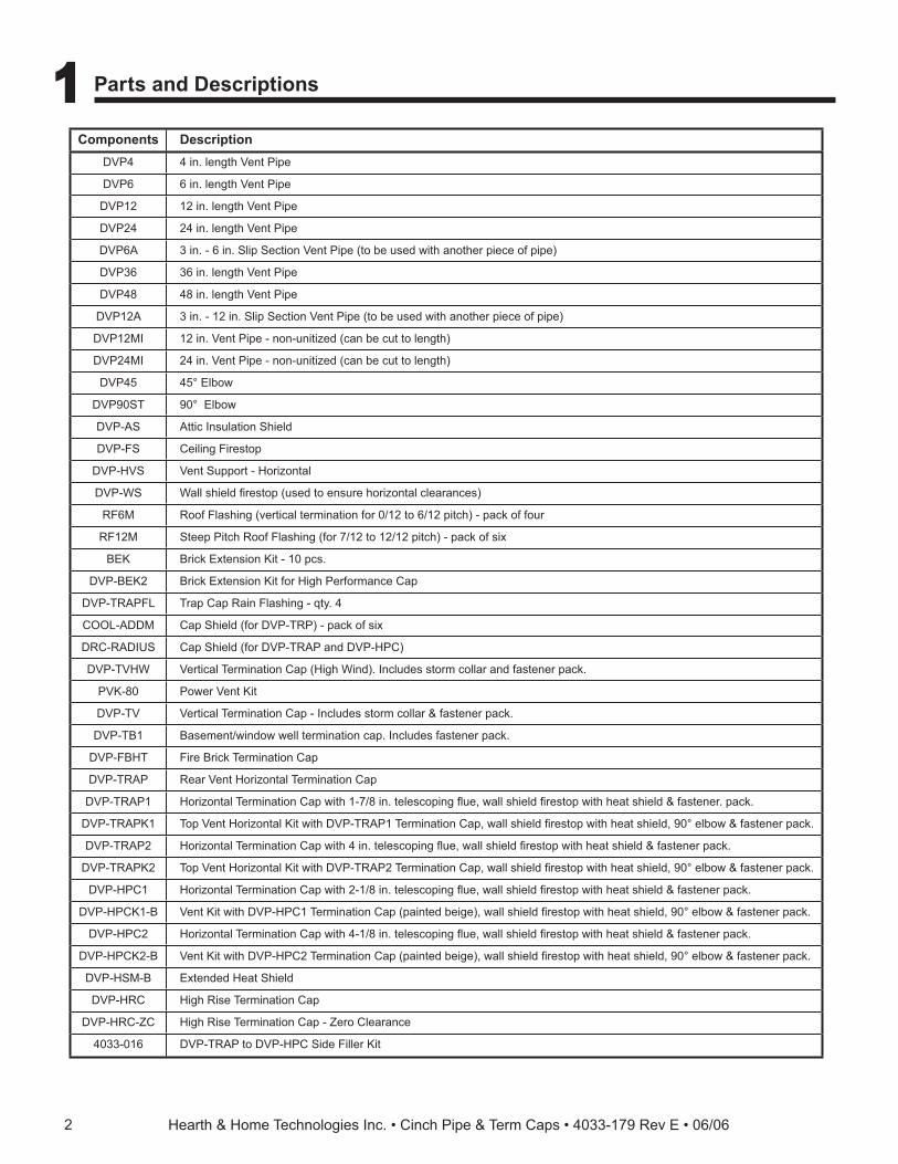
1 1 Parts and Descriptions
Components DescriptionDVP4 4 in. length Vent Pipe
DVP6 6 in. length Vent Pipe
DVP12 12 in. length Vent Pipe
DVP24 24 in. length Vent Pipe
DVP6A 3 in. - 6 in. Slip Section Vent Pipe (to be used with another piece of pipe)
DVP36 36 in. length Vent Pipe
DVP48 48 in. length Vent Pipe
DVP12A 3 in. - 12 in. Slip Section Vent Pipe (to be used with another piece of pipe)
DVP12MI 12 in. Vent Pipe - non-unitized (can be cut to length)
DVP24MI 24 in. Vent Pipe - non-unitized (can be cut to length)
DVP45 45° Elbow
DVP90ST 90° Elbow
DVP-AS Attic Insulation Shield
DVP-FS Ceiling Firestop
DVP-HVS Vent Support - Horizontal
DVP-WS Wall shield fi restop (used to ensure horizontal clearances)
RF6M Roof Flashing (vertical termination for 0/12 to 6/12 pitch) - pack of four
RF12M Steep Pitch Roof Flashing (for 7/12 to 12/12 pitch) - pack of six
BEK Brick Extension Kit - 10 pcs.
DVP-BEK2 Brick Extension Kit for High Performance Cap
DVP-TRAPFL Trap Cap Rain Flashing - qty. 4
COOL-ADDM Cap Shield (for DVP-TRP) - pack of six
DRC-RADIUS Cap Shield (for DVP-TRAP and DVP-HPC)
DVP-TVHW Vertical Termination Cap (High Wind). Includes storm collar and fastener pack.
PVK-80 Power Vent Kit
DVP-TV Vertical Termination Cap - Includes storm collar & fastener pack.
DVP-TB1 Basement/window well termination cap. Includes fastener pack.
DVP-FBHT Fire Brick Termination Cap
DVP-TRAP Rear Vent Horizontal Termination Cap
DVP-TRAP1 Horizontal Termination Cap with 1-7/8 in. telescoping fl ue, wall shield fi restop with heat shield & fastener. pack.
DVP-TRAPK1 Top Vent Horizontal Kit with DVP-TRAP1 Termination Cap, wall shield fi restop with heat shield, 90° elbow & fastener pack.
DVP-TRAP2 Horizontal Termination Cap with 4 in. telescoping fl ue, wall shield fi restop with heat shield & fastener pack.
DVP-TRAPK2 Top Vent Horizontal Kit with DVP-TRAP2 Termination Cap, wall shield fi restop with heat shield, 90° elbow & fastener pack.
DVP-HPC1 Horizontal Termination Cap with 2-1/8 in. telescoping fl ue, wall shield fi restop with heat shield & fastener pack.
DVP-HPCK1-B Vent Kit with DVP-HPC1 Termination Cap (painted beige), wall shield fi restop with heat shield, 90° elbow & fastener pack.
DVP-HPC2 Horizontal Termination Cap with 4-1/8 in. telescoping fl ue, wall shield fi restop with heat shield & fastener pack.
DVP-HPCK2-B Vent Kit with DVP-HPC2 Termination Cap (painted beige), wall shield fi restop with heat shield, 90° elbow & fastener pack.
DVP-HSM-B Extended Heat Shield
DVP-HRC High Rise Termination Cap
DVP-HRC-ZC High Rise Termination Cap - Zero Clearance
4033-016 DVP-TRAP to DVP-HPC Side Filler Kit
Hearth & Home Technologies Inc. • Cinch Pipe & Term Caps • 4033-179 Rev E • 06/06 3
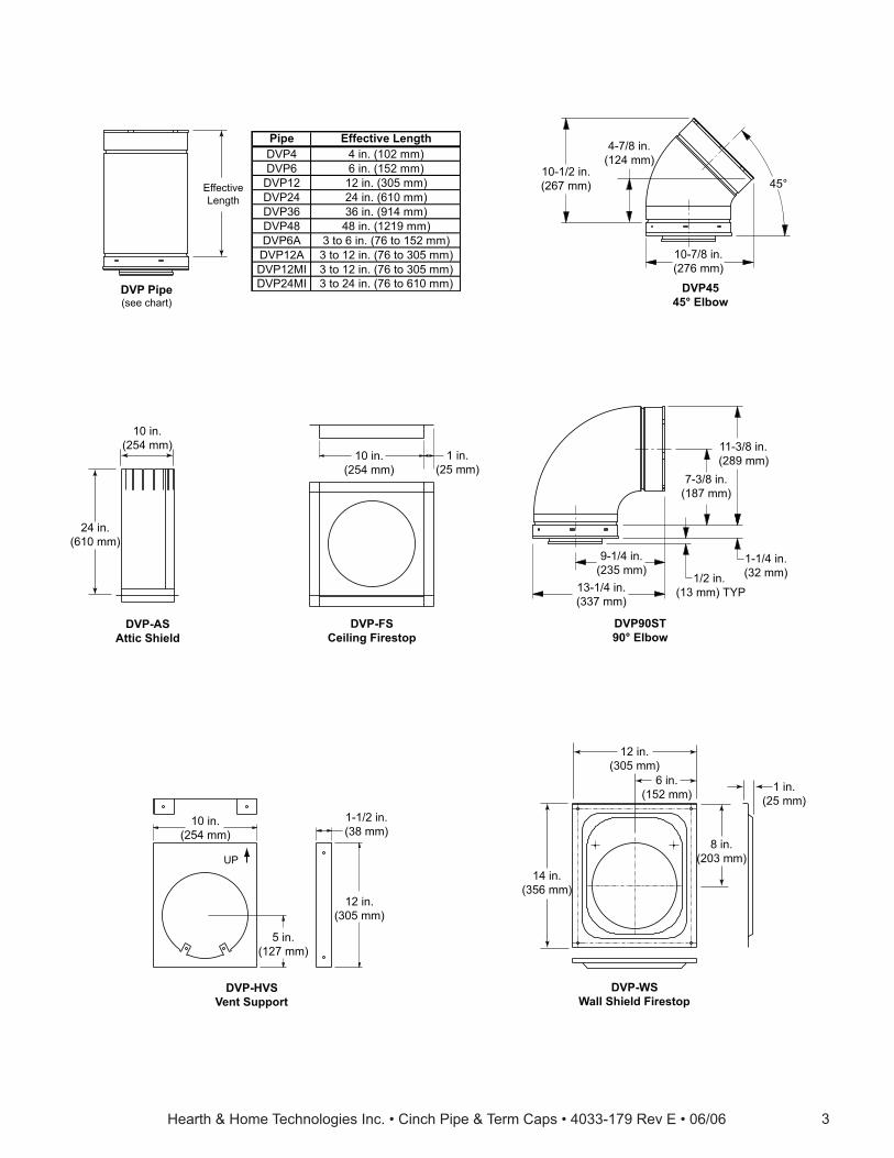
EffectiveLength
DVP Pipe(see chart)
Pipe Effective LengthDVP4 4 in. (102 mm)DVP6 6 in. (152 mm)DVP12 12 in. (305 mm)DVP24 24 in. (610 mm)DVP36 36 in. (914 mm)DVP48 48 in. (1219 mm)DVP6A 3 to 6 in. (76 to 152 mm)DVP12A 3 to 12 in. (76 to 305 mm)DVP12MI 3 to 12 in. (76 to 305 mm)DVP24MI 3 to 24 in. (76 to 610 mm)
10-1/2 in.(267 mm)
10-7/8 in.(276 mm)
DVP4545° Elbow
45°
4-7/8 in.(124 mm)
DVP-ASAttic Shield
10 in.(254 mm)
24 in.(610 mm)
10 in.(254 mm)
1 in.(25 mm)
DVP-FSCeiling Firestop
7-3/8 in.(187 mm)
11-3/8 in.(289 mm)
1-1/4 in.(32 mm)
9-1/4 in.(235 mm)
13-1/4 in.(337 mm)
1/2 in. (13 mm) TYP
DVP90ST90° Elbow
10 in.(254 mm)
1-1/2 in.(38 mm)
5 in.(127 mm)
12 in.(305 mm)
DVP-HVSVent Support
UP
DVP-WSWall Shield Firestop
14 in.(356 mm)
1 in.(25 mm)
8 in.(203 mm)
6 in.(152 mm)
12 in.(305 mm)
Hearth & Home Technologies Inc. • Cinch Pipe & Term Caps • 4033-179 Rev E • 06/064
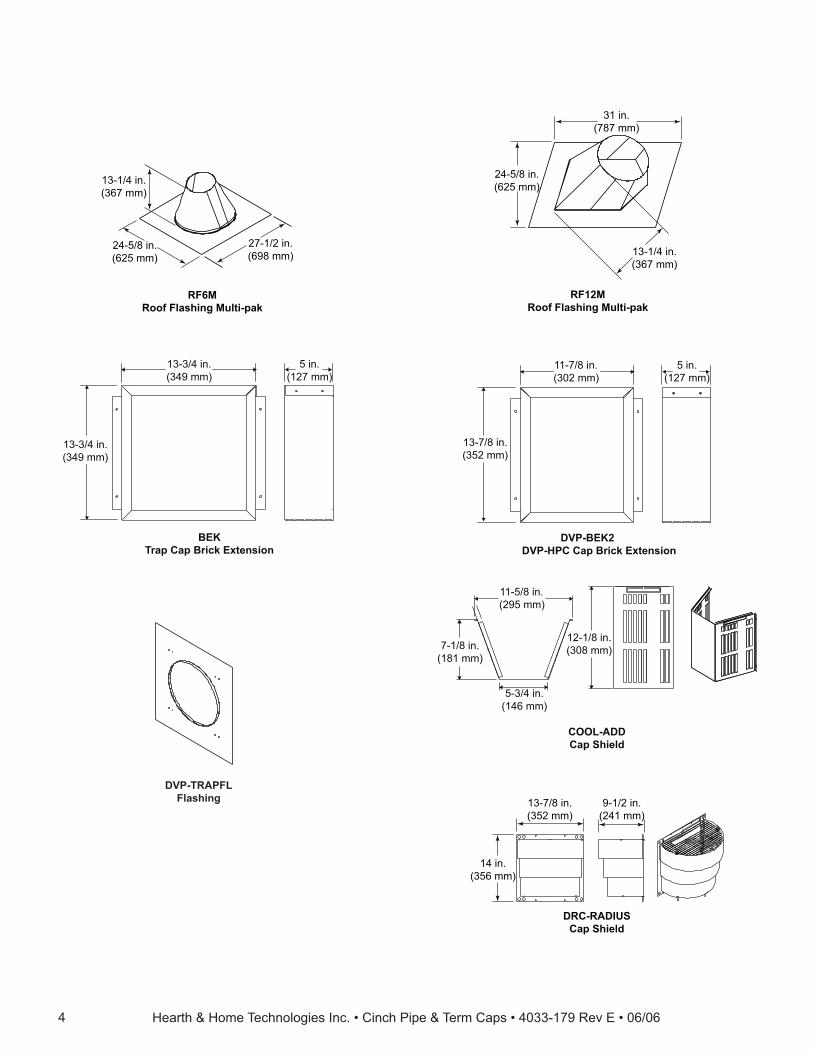
13-1/4 in.(367 mm)
24-5/8 in.(625 mm)
27-1/2 in.(698 mm)
RF6MRoof Flashing Multi-pak
31 in.(787 mm)
24-5/8 in.(625 mm)
13-1/4 in.(367 mm)
RF12MRoof Flashing Multi-pak
BEKTrap Cap Brick Extension
13-3/4 in.(349 mm)
5 in.(127 mm)
13-3/4 in.(349 mm)
DVP-BEK2DVP-HPC Cap Brick Extension
13-7/8 in.(352 mm)
5 in.(127 mm)
11-7/8 in.(302 mm)
COOL-ADDCap Shield
11-5/8 in.(295 mm)
5-3/4 in.(146 mm)
7-1/8 in.(181 mm)
12-1/8 in.(308 mm)
DRC-RADIUSCap Shield
13-7/8 in.(352 mm)
9-1/2 in.(241 mm)
14 in.(356 mm)
DVP-TRAPFLFlashing
Hearth & Home Technologies Inc. • Cinch Pipe & Term Caps • 4033-179 Rev E • 06/06 5
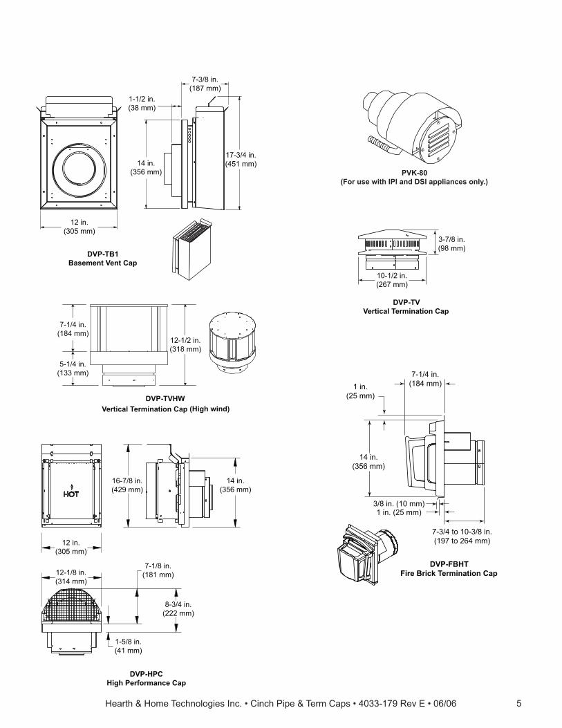
DVP-TB1Basement Vent Cap
12 in.(305 mm)
1-1/2 in.(38 mm)
7-3/8 in.(187 mm)
14 in.(356 mm)
17-3/4 in.(451 mm)
10-1/2 in.(267 mm)
3-7/8 in.(98 mm)
DVP-TVVertical Termination Cap
PVK-80(For use with IPI and DSI appliances only.)
1 in.(25 mm)
14 in.(356 mm)
3/8 in. (10 mm)1 in. (25 mm)
7-1/4 in.(184 mm)
7-3/4 to 10-3/8 in.(197 to 264 mm)
DVP-FBHTFire Brick Termination Cap
7-1/4 in.(184 mm)
5-1/4 in.(133 mm)
12-1/2 in.(318 mm)
DVP-TVHWVertical Termination Cap (High wind)
14 in.(356 mm)
12 in.(305 mm)
12-1/8 in.(314 mm)
7-1/8 in.(181 mm)
8-3/4 in.(222 mm)
1-5/8 in.(41 mm)
16-7/8 in.(429 mm)
DVP-HPCHigh Performance Cap
Hearth & Home Technologies Inc. • Cinch Pipe & Term Caps • 4033-179 Rev E • 06/066
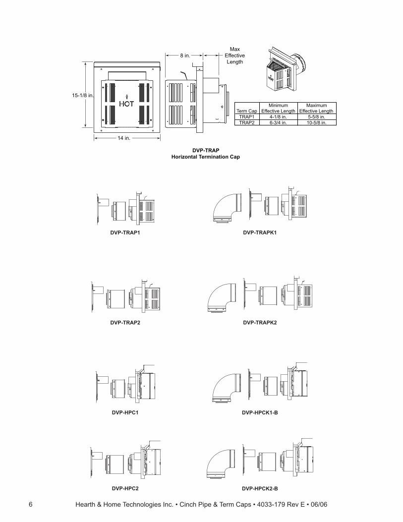
DVP-TRAP1
DVP-TRAP2
DVP-HPC1
DVP-HPCK2-BDVP-HPC2
DVP-TRAPK1
DVP-TRAPK2
DVP-HPCK1-B
DVP-TRAPHorizontal Termination Cap
15-1/8 in.
14 in.
8 in.Max
EffectiveLength
Minimum Maximum Term Cap Effective Length Effective Length TRAP1 4-1/8 in. 5-5/8 in. TRAP2 6-3/4 in. 10-5/8 in.
Hearth & Home Technologies Inc. • Cinch Pipe & Term Caps • 4033-179 Rev E • 06/06 7
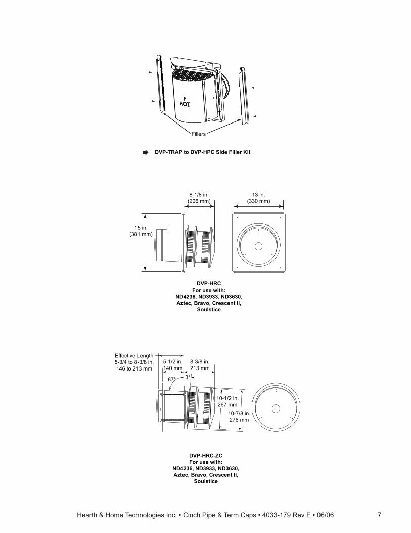
13 in.(330 mm)
15 in.(381 mm)
8-1/8 in.(206 mm)
DVP-HRCFor use with:
ND4236, ND3933, ND3630,Aztec, Bravo, Crescent II,
Soulstice
10-7/8 in.276 mm
10-1/2 in.267 mm
3°87°
Effective Length5-3/4 to 8-3/8 in.146 to 213 mm
5-1/2 in.140 mm
8-3/8 in.213 mm
DVP-HRC-ZCFor use with:
ND4236, ND3933, ND3630,Aztec, Bravo, Crescent II,
Soulstice
Fillers
DVP-TRAP to DVP-HPC Side Filler Kit�
Hearth & Home Technologies Inc. • Cinch Pipe & Term Caps • 4033-179 Rev E • 06/068
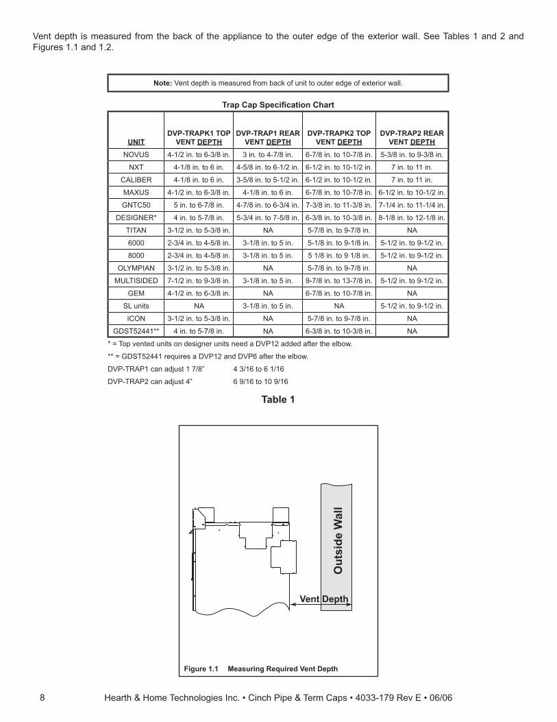
Vent depth is measured from the back of the appliance to the outer edge of the exterior wall. See Tables 1 and 2 and Figures 1.1 and 1.2.
Out
side
Wal
l
Vent Depth
Figure 1.1 Measuring Required Vent Depth
Table 1
Note: Vent depth is measured from back of unit to outer edge of exterior wall.
Trap Cap Specifi cation Chart
UNITDVP-TRAPK1 TOP
VENT DEPTHDVP-TRAP1 REAR
VENT DEPTHDVP-TRAPK2 TOP
VENT DEPTHDVP-TRAP2 REAR
VENT DEPTHNOVUS 4-1/2 in. to 6-3/8 in. 3 in. to 4-7/8 in. 6-7/8 in. to 10-7/8 in. 5-3/8 in. to 9-3/8 in.
NXT 4-1/8 in. to 6 in. 4-5/8 in. to 6-1/2 in. 6-1/2 in. to 10-1/2 in. 7 in. to 11 in.
CALIBER 4-1/8 in. to 6 in. 3-5/8 in. to 5-1/2 in. 6-1/2 in. to 10-1/2 in. 7 in. to 11 in.
MAXUS 4-1/2 in. to 6-3/8 in. 4-1/8 in. to 6 in. 6-7/8 in. to 10-7/8 in. 6-1/2 in. to 10-1/2 in.
GNTC50 5 in. to 6-7/8 in. 4-7/8 in. to 6-3/4 in. 7-3/8 in. to 11-3/8 in. 7-1/4 in. to 11-1/4 in.
DESIGNER* 4 in. to 5-7/8 in. 5-3/4 in. to 7-5/8 in. 6-3/8 in. to 10-3/8 in. 8-1/8 in. to 12-1/8 in.
TITAN 3-1/2 in. to 5-3/8 in. NA 5-7/8 in. to 9-7/8 in. NA
6000 2-3/4 in. to 4-5/8 in. 3-1/8 in. to 5 in. 5-1/8 in. to 9-1/8 in. 5-1/2 in. to 9-1/2 in.
8000 2-3/4 in. to 4-5/8 in. 3-1/8 in. to 5 in. 5 1/8 in. to 9 1/8 in. 5-1/2 in. to 9-1/2 in.
OLYMPIAN 3-1/2 in. to 5-3/8 in. NA 5-7/8 in. to 9-7/8 in. NA
MULTISIDED 7-1/2 in. to 9-3/8 in. 3-1/8 in. to 5 in. 9-7/8 in. to 13-7/8 in. 5-1/2 in. to 9-1/2 in.
GEM 4-1/2 in. to 6-3/8 in. NA 6-7/8 in. to 10-7/8 in. NA
SL units NA 3-1/8 in. to 5 in. NA 5-1/2 in. to 9-1/2 in.
ICON 3-1/2 in. to 5-3/8 in. NA 5-7/8 in. to 9-7/8 in. NA
GDST52441** 4 in. to 5-7/8 in. NA 6-3/8 in. to 10-3/8 in. NA
* = Top vented units on designer units need a DVP12 added after the elbow.
** = GDST52441 requires a DVP12 and DVP6 after the elbow.
DVP-TRAP1 can adjust 1 7/8” 4 3/16 to 6 1/16
DVP-TRAP2 can adjust 4” 6 9/16 to 10 9/16
Hearth & Home Technologies Inc. • Cinch Pipe & Term Caps • 4033-179 Rev E • 06/06 9
Out
side
Wal
l
Vent Depth
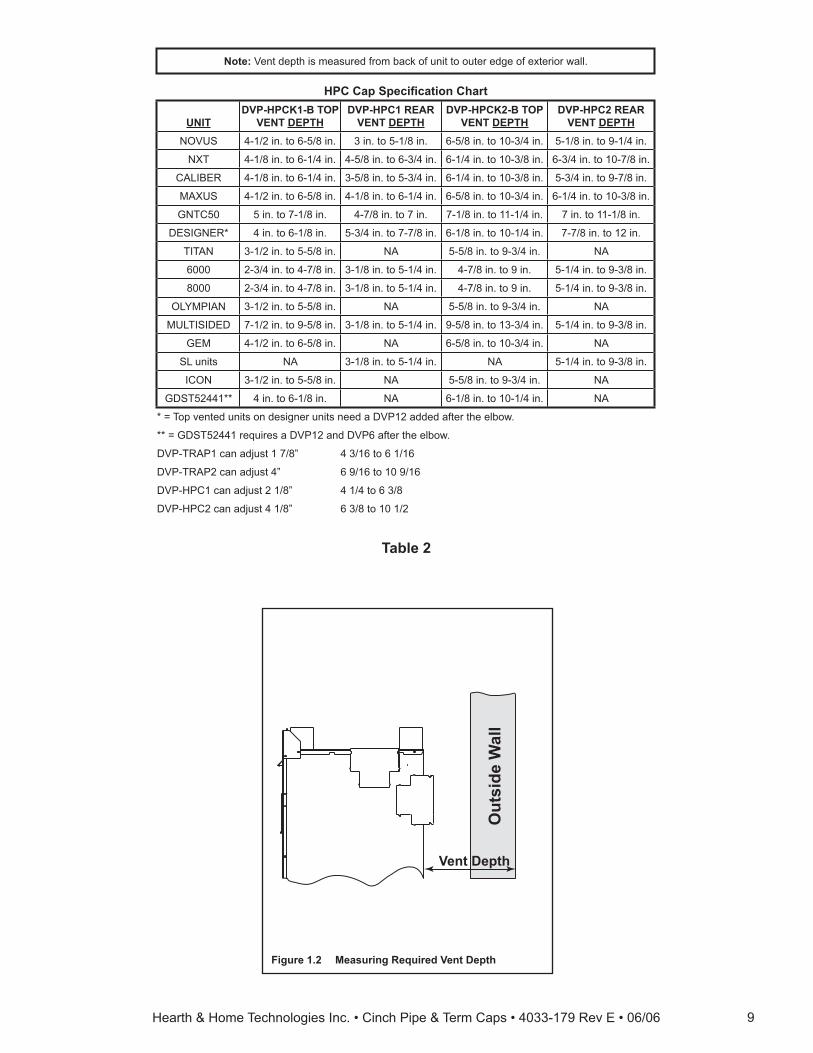
Table 2
Figure 1.2 Measuring Required Vent Depth
Note: Vent depth is measured from back of unit to outer edge of exterior wall.
HPC Cap Specifi cation Chart
UNITDVP-HPCK1-B TOP
VENT DEPTHDVP-HPC1 REAR
VENT DEPTHDVP-HPCK2-B TOP
VENT DEPTHDVP-HPC2 REAR
VENT DEPTHNOVUS 4-1/2 in. to 6-5/8 in. 3 in. to 5-1/8 in. 6-5/8 in. to 10-3/4 in. 5-1/8 in. to 9-1/4 in.
NXT 4-1/8 in. to 6-1/4 in. 4-5/8 in. to 6-3/4 in. 6-1/4 in. to 10-3/8 in. 6-3/4 in. to 10-7/8 in.
CALIBER 4-1/8 in. to 6-1/4 in. 3-5/8 in. to 5-3/4 in. 6-1/4 in. to 10-3/8 in. 5-3/4 in. to 9-7/8 in.
MAXUS 4-1/2 in. to 6-5/8 in. 4-1/8 in. to 6-1/4 in. 6-5/8 in. to 10-3/4 in. 6-1/4 in. to 10-3/8 in.
GNTC50 5 in. to 7-1/8 in. 4-7/8 in. to 7 in. 7-1/8 in. to 11-1/4 in. 7 in. to 11-1/8 in.
DESIGNER* 4 in. to 6-1/8 in. 5-3/4 in. to 7-7/8 in. 6-1/8 in. to 10-1/4 in. 7-7/8 in. to 12 in.
TITAN 3-1/2 in. to 5-5/8 in. NA 5-5/8 in. to 9-3/4 in. NA
6000 2-3/4 in. to 4-7/8 in. 3-1/8 in. to 5-1/4 in. 4-7/8 in. to 9 in. 5-1/4 in. to 9-3/8 in.
8000 2-3/4 in. to 4-7/8 in. 3-1/8 in. to 5-1/4 in. 4-7/8 in. to 9 in. 5-1/4 in. to 9-3/8 in.
OLYMPIAN 3-1/2 in. to 5-5/8 in. NA 5-5/8 in. to 9-3/4 in. NA
MULTISIDED 7-1/2 in. to 9-5/8 in. 3-1/8 in. to 5-1/4 in. 9-5/8 in. to 13-3/4 in. 5-1/4 in. to 9-3/8 in.
GEM 4-1/2 in. to 6-5/8 in. NA 6-5/8 in. to 10-3/4 in. NA
SL units NA 3-1/8 in. to 5-1/4 in. NA 5-1/4 in. to 9-3/8 in.
ICON 3-1/2 in. to 5-5/8 in. NA 5-5/8 in. to 9-3/4 in. NA
GDST52441** 4 in. to 6-1/8 in. NA 6-1/8 in. to 10-1/4 in. NA
* = Top vented units on designer units need a DVP12 added after the elbow.
** = GDST52441 requires a DVP12 and DVP6 after the elbow.
DVP-TRAP1 can adjust 1 7/8” 4 3/16 to 6 1/16
DVP-TRAP2 can adjust 4” 6 9/16 to 10 9/16
DVP-HPC1 can adjust 2 1/8” 4 1/4 to 6 3/8
DVP-HPC2 can adjust 4 1/8” 6 3/8 to 10 1/2
Hearth & Home Technologies Inc. • Cinch Pipe & Term Caps • 4033-179 Rev E • 06/0610
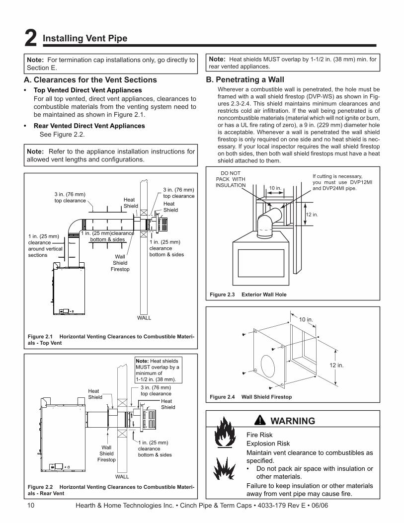
3 in. (76 mm)top clearance
1 in. (25 mm)clearancebottom & sides
HeatShield
WallShield
Firestop
HeatShield
WALL
Note: Heat shieldsMUST overlap by aminimum of1-1/2 in. (38 mm).
Figure 2.2 Horizontal Venting Clearances to Combustible Materi-als - Rear Vent
A. Clearances for the Vent Sections• Top Vented Direct Vent Appliances
For all top vented, direct vent appliances, clearances to combustible materials from the venting system need to be maintained as shown in Figure 2.1.
• Rear Vented Direct Vent Appliances See Figure 2.2.
3 in. (76 mm)top clearance
1 in. (25 mm)clearancebottom & sides1 in. (25 mm)
clearancearound verticalsections
3 in. (76 mm)top clearance
1 in. (25 mm) clearancebottom & sides
HeatShield
WallShield
Firestop
HeatShield
WALL
Figure 2.1 Horizontal Venting Clearances to Combustible Materi-als - Top Vent
Note: For termination cap installations only, go directly to Section E.
Note: Refer to the appliance installation instructions for allowed vent lengths and confi gurations.
2 Installing Vent Pipe
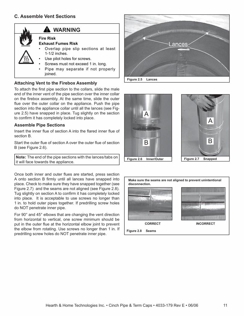
B. Penetrating a WallWherever a combustible wall is penetrated, the hole must be framed with a wall shield fi restop (DVP-WS) as shown in Fig-ures 2.3-2.4. This shield maintains minimum clearances and restricts cold air infi ltration. If the wall being penetrated is of noncombustible materials (material which will not ignite or burn, or has a UL fi re rating of zero), a 9 in. (229 mm) diameter hole is acceptable. Whenever a wall is penetrated the wall shield fi restop is only required on one side and no heat shield is nec-essary. If your local inspector requires the wall shield fi restop on both sides, then both wall shield fi restops must have a heat shield attached to them.
10 in.
12 in.
Figure 2.4 Wall Shield Firestop
Figure 2.3 Exterior Wall Hole
If cutting is necessary,you must use DVP12MIand DVP24MI pipe.
DO NOTPACK WITHINSULATION 10 in.
12 in.
Note: Heat shields MUST overlap by 1-1/2 in. (38 mm) min. for rear vented appliances.
Fire RiskExplosion RiskMaintain vent clearance to combustibles as specifi ed.• Do not pack air space with insulation or
other materials.Failure to keep insulation or other materials away from vent pipe may cause fi re.
WARNING
Hearth & Home Technologies Inc. • Cinch Pipe & Term Caps • 4033-179 Rev E • 06/06 11
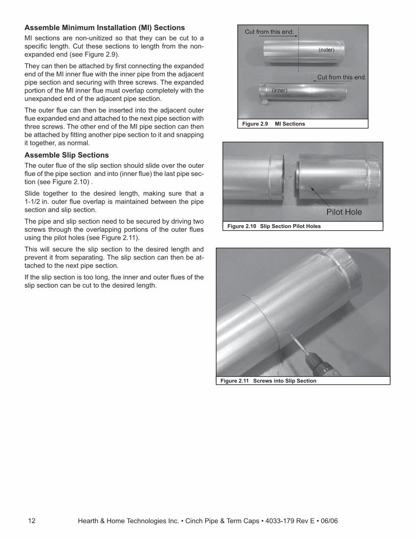
C. Assemble Vent Sections
Figure 2.5 Lances
A
B
Figure 2.6 Inner/Outer
A
B
Figure 2.7 Snapped
CORRECT INCORRECT
Make sure the seams are not aligned to prevent unintentional disconnection.
Figure 2.8 Seams
Fire RiskExhaust Fumes Risk• Overlap pipe slip sections at least
1-1/2 inches.• Use pilot holes for screws.• Screws must not exceed 1 in. long.• Pipe may separate if not properly
joined.
WARNING
Attaching Vent to the Firebox AssemblyTo attach the fi rst pipe section to the collars, slide the male end of the inner vent of the pipe section over the inner collar on the fi rebox assembly. At the same time, slide the outer fl ue over the outer collar on the appliance. Push the pipe section into the appliance collar until all the lances (see Fig-ure 2.5) have snapped in place. Tug slightly on the section to confi rm it has completely locked into place.
Assemble Pipe SectionsInsert the inner fl ue of section A into the fl ared inner fl ue of section B.
Start the outer fl ue of section A over the outer fl ue of section B (see Figure 2.6).
Note: The end of the pipe sections with the lances/tabs on it will face towards the appliance.
Once both inner and outer fl ues are started, press section A onto section B fi rmly until all lances have snapped into place. Check to make sure they have snapped together (see Figure 2.7) and the seams are not aligned (see Figure 2.8). Tug slightly on section A to confi rm it has completely locked into place. It is acceptable to use screws no longer than 1 in. to hold outer pipes together. If predrilling screw holes do NOT penetrate inner pipe.
For 90° and 45° elbows that are changing the vent direction from horizontal to vertical, one screw minimum should be put in the outer fl ue at the horizontal elbow joint to prevent the elbow from rotating. Use screws no longer than 1 in. If predrilling screw holes do NOT penetrate inner pipe.
Hearth & Home Technologies Inc. • Cinch Pipe & Term Caps • 4033-179 Rev E • 06/0612
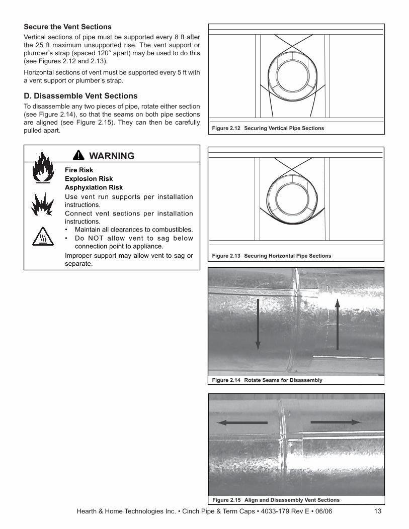
Assemble Minimum Installation (MI) SectionsMI sections are non-unitized so that they can be cut to a specifi c length. Cut these sections to length from the non-expanded end (see Figure 2.9).
They can then be attached by fi rst connecting the expanded end of the MI inner fl ue with the inner pipe from the adjacent pipe section and securing with three screws. The expanded portion of the MI inner fl ue must overlap completely with the unexpanded end of the adjacent pipe section.
The outer fl ue can then be inserted into the adjacent outer fl ue expanded end and attached to the next pipe section with three screws. The other end of the MI pipe section can then be attached by fi tting another pipe section to it and snapping it together, as normal.
Assemble Slip SectionsThe outer fl ue of the slip section should slide over the outer fl ue of the pipe section and into (inner fl ue) the last pipe sec-tion (see Figure 2.10) .
Slide together to the desired length, making sure that a 1-1/2 in. outer fl ue overlap is maintained between the pipe section and slip section.
The pipe and slip section need to be secured by driving two screws through the overlapping portions of the outer fl ues using the pilot holes (see Figure 2.11).
This will secure the slip section to the desired length and prevent it from separating. The slip section can then be at-tached to the next pipe section.
If the slip section is too long, the inner and outer fl ues of the slip section can be cut to the desired length.
Figure 2.9 MI Sections
Figure 2.10 Slip Section Pilot Holes
Figure 2.11 Screws into Slip Section
Hearth & Home Technologies Inc. • Cinch Pipe & Term Caps • 4033-179 Rev E • 06/06 13
Secure the Vent SectionsVertical sections of pipe must be supported every 8 ft after the 25 ft maximum unsupported rise. The vent support or plumber’s strap (spaced 120° apart) may be used to do this (see Figures 2.12 and 2.13).
Horizontal sections of vent must be supported every 5 ft with a vent support or plumber’s strap.
D. Disassemble Vent SectionsTo disassemble any two pieces of pipe, rotate either section (see Figure 2.14), so that the seams on both pipe sections are aligned (see Figure 2.15). They can then be carefully pulled apart. Figure 2.12 Securing Vertical Pipe Sections
Figure 2.13 Securing Horizontal Pipe Sections
Fire RiskExplosion RiskAsphyxiation RiskUse vent run supports per installation instructions.Connect vent sections per installation instructions.• Maintain all clearances to combustibles.• Do NOT allow vent to sag below
connection point to appliance.Improper support may allow vent to sag or separate.
WARNING
Figure 2.14 Rotate Seams for Disassembly
Figure 2.15 Align and Disassembly Vent Sections
Hearth & Home Technologies Inc. • Cinch Pipe & Term Caps • 4033-179 Rev E • 06/0614
Burn Risk• Local codes may require installation of a
cap shield to prevent anything or anyone from touching the hot cap.
WARNING
Do NOT connect a pipe section to a termination cap without using the telescoping fl ue section found on the termination cap.
WARNING
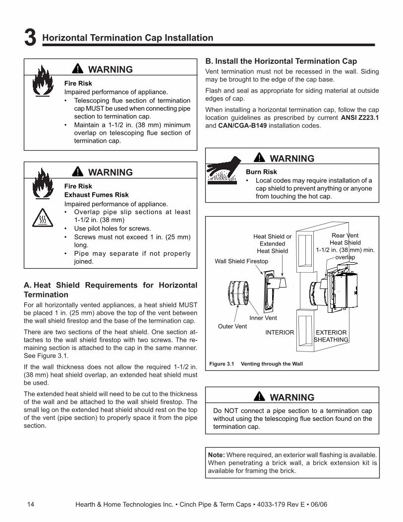
A. Heat Shield Requirements for Horizontal TerminationFor all horizontally vented appliances, a heat shield MUST be placed 1 in. (25 mm) above the top of the vent between the wall shield fi restop and the base of the termination cap.
There are two sections of the heat shield. One section at-taches to the wall shield fi restop with two screws. The re-maining section is attached to the cap in the same manner. See Figure 3.1.
If the wall thickness does not allow the required 1-1/2 in. (38 mm) heat shield overlap, an extended heat shield must be used.
The extended heat shield will need to be cut to the thickness of the wall and be attached to the wall shield fi restop. The small leg on the extended heat shield should rest on the top of the vent (pipe section) to properly space it from the pipe section.
Note: Where required, an exterior wall fl ashing is available. When penetrating a brick wall, a brick extension kit is available for framing the brick.
INTERIOR
Heat Shield orExtended
Heat Shield
Wall Shield Firestop
Inner VentOuter Vent
Rear VentHeat Shield
1-1/2 in. (38 mm) min.overlap
EXTERIORSHEATHING
Figure 3.1 Venting through the Wall
B. Install the Horizontal Termination CapVent termination must not be recessed in the wall. Siding may be brought to the edge of the cap base.
Flash and seal as appropriate for siding material at outside edges of cap.
When installing a horizontal termination cap, follow the cap location guidelines as prescribed by current ANSI Z223.1 and CAN/CGA-B149 installation codes.
Fire RiskExhaust Fumes RiskImpaired performance of appliance.• Overlap pipe slip sections at least
1-1/2 in. (38 mm)• Use pilot holes for screws.• Screws must not exceed 1 in. (25 mm)
long.• Pipe may separate if not properly
joined.
WARNING
Fire RiskImpaired performance of appliance.• Telescoping fl ue section of termination
cap MUST be used when connecting pipe section to termination cap.
• Maintain a 1-1/2 in. (38 mm) minimum overlap on telescoping fl ue section of termination cap.
WARNING
3 Horizontal Termination Cap Installation
Hearth & Home Technologies Inc. • Cinch Pipe & Term Caps • 4033-179 Rev E • 06/06 15
C. High Rise Cap (DVP-HRC, DVP-HRC-ZC) (only for use with ND4236, ND3933, ND3630, Aztec, Bravo, Crescent II & Soulstice)
• These caps are NOT approved for use on vinyl walls.• Caps must be a minimum of 48 in. (122 cm) from any
soffi t.• Cap must be installed with arrows pointing upward.
Note: Arrows are on the bottom dishes and a label showing “UP” will be on the end dish.
• The slip section for the caps is specially made for the HRC caps.
• The slip section must be installed with the outer seam always on the bottom.
• The HRC caps are only approved for top vent applications.
• The DVP-HRC caps are for combustible or wood frame installations.
Caps are made from 100% stainless steel and are offered in a painted beige color. An unpainted cap is not offered nor will there be a kit.
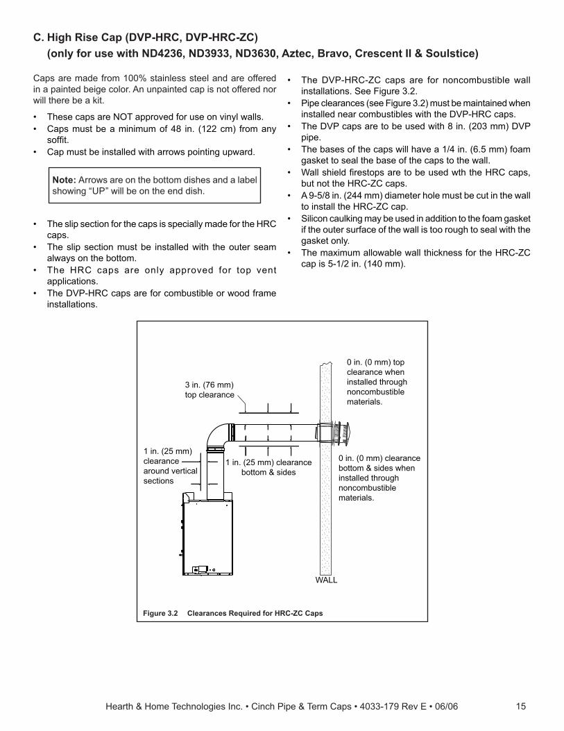
3 in. (76 mm)top clearance
1 in. (25 mm) clearancebottom & sides
1 in. (25 mm)clearancearound verticalsections
WALL
0 in. (0 mm) top clearance when installed through noncombustible materials.
0 in. (0 mm) clearance bottom & sides when installed through noncombustible materials.
Figure 3.2 Clearances Required for HRC-ZC Caps
• The DVP-HRC-ZC caps are for noncombustible wall installations. See Figure 3.2.
• Pipe clearances (see Figure 3.2) must be maintained when installed near combustibles with the DVP-HRC caps.
• The DVP caps are to be used with 8 in. (203 mm) DVP pipe.
• The bases of the caps will have a 1/4 in. (6.5 mm) foam gasket to seal the base of the caps to the wall.
• Wall shield fi restops are to be used wth the HRC caps, but not the HRC-ZC caps.
• A 9-5/8 in. (244 mm) diameter hole must be cut in the wall to install the HRC-ZC cap.
• Silicon caulking may be used in addition to the foam gasket if the outer surface of the wall is too rough to seal with the gasket only.
• The maximum allowable wall thickness for the HRC-ZC cap is 5-1/2 in. (140 mm).
Hearth & Home Technologies Inc. • Cinch Pipe & Term Caps • 4033-179 Rev E • 06/0616
Note: The ceiling fi restop is not required if attic insulation shield is used.
B. Install Attic Insulation Shield• Frame opening for attic insulation shield.• Attic insulation shield may be installed above or below
ceiling (see Figure 4.2).• Secure with three fasteners on each side.• Fold tabs at top of attic shield in toward vent pipe. Tabs
must keep vent pipe centered within shield.• Field construct additional shield height if insulation is
deeper than height of attic shield.
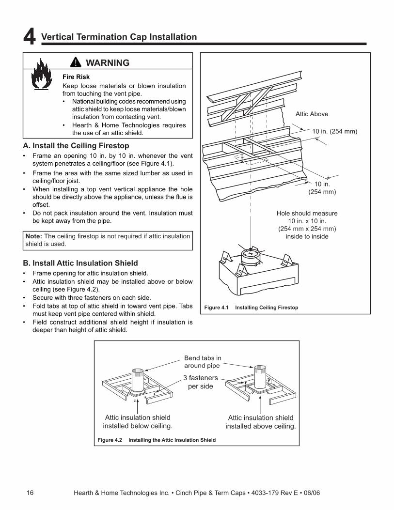
Attic Above
10 in. (254 mm)
Hole should measure10 in. x 10 in.
(254 mm x 254 mm)inside to inside
10 in.(254 mm)
Figure 4.1 Installing Ceiling Firestop
3 fastenersper side
Attic insulation shieldinstalled below ceiling.
Attic insulation shieldinstalled above ceiling.
Bend tabs inaround pipe
Figure 4.2 Installing the Attic Insulation Shield
Fire RiskKeep loose materials or blown insulation from touching the vent pipe.• National building codes recommend using
attic shield to keep loose materials/blown insulation from contacting vent.
• Hearth & Home Technologies requires the use of an attic shield.
WARNING
A. Install the Ceiling Firestop• Frame an opening 10 in. by 10 in. whenever the vent
system penetrates a ceiling/fl oor (see Figure 4.1).• Frame the area with the same sized lumber as used in
ceiling/fl oor joist.• When installing a top vent vertical appliance the hole
should be directly above the appliance, unless the fl ue is offset.
• Do not pack insulation around the vent. Insulation must be kept away from the pipe.
4 Vertical Termination Cap Installation
Hearth & Home Technologies Inc. • Cinch Pipe & Term Caps • 4033-179 Rev E • 06/06 17
Figure 4.4 Secure with Screws
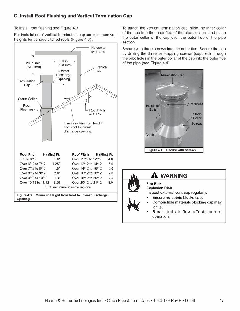
C. Install Roof Flashing and Vertical Termination Cap
To attach the vertical termination cap, slide the inner collar of the cap into the inner fl ue of the pipe section and place the outer collar of the cap over the outer fl ue of the pipe section.
Secure with three screws into the outer fl ue. Secure the cap by driving the three self-tapping screws (supplied) through the pilot holes in the outer collar of the cap into the outer fl ue of the pipe (see Figure 4.4).
Horizontaloverhang
12X
20 in.(508 mm)
LowestDischargeOpening
TerminationCap
Roof Pitchis X / 12
Verticalwall
H (min.) - Minimum heightfrom roof to lowestdischarge opening.
24 in. min.(610 mm)
Roof Pitch H (Min.) Ft. Roof Pitch H (Min.) Ft.Flat to 6/12 1.0* Over 11/12 to 12/12 4.0Over 6/12 to 7/12 1.25* Over 12/12 to 14/12 5.0Over 7/12 to 8/12 1.5* Over 14/12 to 16/12 6.0Over 8/12 to 9/12 2.0* Over 16/12 to 18/12 7.0Over 9/12 to 10/12 2.5 Over 18/12 to 20/12 7.5Over 10/12 to 11/12 3.25 Over 20/12 to 21/12 8.0
* 3 ft. minimum in snow regions
Storm Collar
RoofFlashing
Figure 4.3 Minimum Height from Roof to Lowest Discharge Opening
To install roof fl ashing see Figure 4.3.
For installation of vertical termination cap see minimum vent heights for various pitched roofs (Figure 4.3) .
Fire RiskExplosion RiskInspect external vent cap regularly.• Ensure no debris blocks cap.• Combustible materials blocking cap may
ignite.• Restricted air f low affects burner
operation.
WARNING
StormCollar
Termination Cap
(1 of three)
Caulk
Screws
Brackets/Bolts
Hearth & Home Technologies Inc. • Cinch Pipe & Term Caps • 4033-179 Rev E • 06/0618
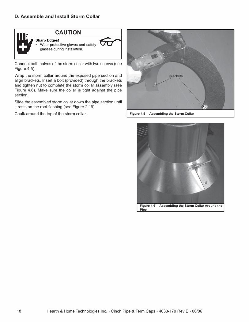
D. Assemble and Install Storm Collar
Connect both halves of the storm collar with two screws (see Figure 4.5).
Wrap the storm collar around the exposed pipe section and align brackets. Insert a bolt (provided) through the brackets and tighten nut to complete the storm collar assembly (see Figure 4.6). Make sure the collar is tight against the pipe section.
Slide the assembled storm collar down the pipe section until it rests on the roof fl ashing (see Figure 2.19).
Caulk around the top of the storm collar.
Sharp Edges!• Wear protective gloves and safety
glasses during installation.
CAUTION
Figure 4.6 Assembling the Storm Collar Around the Pipe
Figure 4.5 Assembling the Storm Collar
Hearth & Home Technologies Inc. • Cinch Pipe & Term Caps • 4033-179 Rev E • 06/06 19
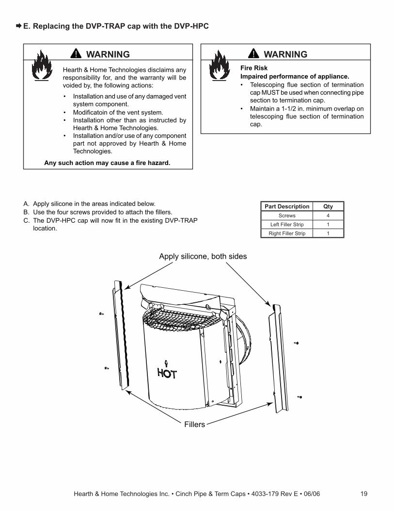
E. Replacing the DVP-TRAP cap with the DVP-HPC
A. Apply silicone in the areas indicated below.B. Use the four screws provided to attach the fi llers.C. The DVP-HPC cap will now fi t in the existing DVP-TRAP
location.
Fire RiskImpaired performance of appliance.• Telescoping fl ue section of termination
cap MUST be used when connecting pipe section to termination cap.
• Maintain a 1-1/2 in. minimum overlap on telescoping fl ue section of termination cap.
WARNING
Apply silicone, both sides
Fillers
Part Description QtyScrews 4
Left Filler Strip 1
Right Filler Strip 1
Hearth & Home Technologies disclaims any responsibility for, and the warranty will be voided by, the following actions:
• Installation and use of any damaged vent system component.
• Modifi catoin of the vent system.• Installation other than as instructed by
Hearth & Home Technologies.• Installation and/or use of any component
part not approved by Hearth & Home Technologies.
Any such action may cause a fi re hazard.
WARNING
�

Hearth & Home Technologies Inc. • Cinch Pipe & Term Caps • 4033-179 Rev E • 06/0620