Embed Size (px)
Citation preview

Shaken,not stirred!
See page 5
Growing demand
There is a clear and growing demand foradvanced diagnostic testing, to which theinclusion of PAX Diagnostics complimentsMegger’s extensive range of transformertest range of products. The Pax productlines coupled with the expert knowledgeof former Pax staff enables customers tomove toward predictive test regimes withthe capability to detect and diagnoseelectro-mechanical and insulationproblems within power transformers,potentially saving time and money asresources can be directed toward wherethey are needed most. The technologyprovides customers with an extensivetransformer test offer that will proveinvaluable to users who work fortransformer OEMs, service companies andpower utilities.
enables customers to move towardpredictive test regimes, potentially savingtime and money as resources can bedirected toward where they are neededmost”. Natural choice “Megger is a naturalchoice for Pax”, said Peter Fagerström, CEOfor Pax. “Our vision from the start of Paxfour years ago was to be a top player in theinternational power transformer testequipment market. Our products fit perfectwith the Megger transformer productportfolio and together we will create thestrongest product line in the industry toaddress end user concerns”.
Adding confidence
“The Megger brand will add confidence tothe Pax products,” says Matz Ohlen,marketing and sales director at Pax. “Weinvented the first DFR/FDS field instrumentand now it will carry the Megger brandname, and will be supported throughMegger sales and applications staffworldwide”.
Megger Group has announced that hasacquired Pax Diagnostics of Sweden. Paxtransformer testing and insulationdiagnostics products will be a strongaddition to the Megger range of testinstruments for the power industry. Theproducts will be rebranded to Megger,although the IDAX and FRAX product nameswill be retained. Customers can continue tobuy Pax products through existingdistributors. All former Pax employees willtransfer to Megger, and customers cancontinue to deal with their usual contacts.
Industrial logic
The Pax line of dielectric frequency responseanalysers and sweep frequency analysisproducts are complementary to Megger’sexisting line of transformer test equipmentsuch as transformer ohmmeters,transformer turns ratio meters andinsulation testers. While Megger is investingheavily in its existing technology, the Paxproduct line was seen as a way to acceleratethe company’s growth, and give customersaccess to advanced diagnostic conditioningtechnology as well as the test products.Combining the two technological bases notonly gives customers access to a completeline of transformer conditioning andmaintenance testing equipment, but alsohelps accelerate Megger’s growth plans.
Dielectric Frequency ResponseAnalyzers
The IDAX range of Dielectric FrequencyResponse Analyzers is designed formeasuring moisture in power transformersas well as testing insulation material invarious power system products. TheIDAX300 represents the latest generation inthe well-known IDA/IDAX range ofinstruments and represents a breakthrough
in terms of weight-performance ratio. Withits optimized design the test set is threetimes smaller and lighter and performsinsulation characterization twice as fast as itspredecessor IDA200.
Sweep Frequency Analysis products
The FRAX range of Sweep FrequencyAnalysis products is designed for detectingelectromechanical changes inside powertransformers. The products have the highestmeasurement range and accuracy in theindustry and fulfil all recent internationalstandards and recommendations for SFRAtesting.
Advanced diagnostic testing technology
“We have seen a growing demand foradvanced diagnostic testing technology, andthe inclusion of the Pax Diagnostics businessenables Megger to provide a completetransformer test solution”, said Greg Wolfeof Megger. “The Pax product line coupledwith the expert knowledge of Pax staff
Dr Andrew DoddsDirector of Group Development
Power Distribution
Demand for the refurbishment and expansionof power transmission and distributioninfrastructure is expected to remain strong inall regions, in spite of fears that a globalrecession could affect financing costs.
Ensuring that ageing power distributioninfrastructure in developed countries such asUK, Germany or USA means that theincidence of equipment failure is rising.Customer service quality targets are in dangeror not being met, and power systems that arein many cases reaching the end of theirlifetimes may be about to cause severeproblems to power utilities and theircustomers. See page 2 for a detaileddiscussion.
Magnetic Materials
Magnets are used in many industries:generators and motors, microphones,telephones, receivers, clutches and brakes,relays, sensors and of course test andmeasurement instruments.
In a new series of articles on developments inmagnetic materials and magnetics. Dr StanZurek will describe some interestingapplications of magnetics to test andmeasurement technologies. In this first piece,Dr Zurek outlines some classifications ofmagnetics in terms of its physical, structuraland engineering properties, with a usefulsummary diagram to explain how theclassifications fit together. See page 6 for thefull story.
Developments in therapidly developing world of FrequencyResponse Analysis
See page 4
Published by MeggerJanuary 2009
The industry’s recognised information tool
ELECTRICALTESTER
Pax joins Megger Group toexpand transformer testproduct line
We view technology improvements andenvironment protection as key factors in ourmission to supply test and measurementequipment throughout the world. As proof ofour commitment to the environment,Megger’s site in Dover England, and theProgramma site in Täby, Sweden are bothaccredited to ISO14001:2000
Please pass this onto a colleague andrecycle when you have finished with it.
Dealing with a recession
Managers need to manage. Sounds obvious, buttroubled times are when great managers canreally make a difference. There are opportunitiesas well as threats ahead for organisations thatadapt most quickly to the changing economicclimate. But unfortunately, it’s now official.Countries of the world are either in or about toenter recession. Rising commodity prices,restricted access to finance and volatility in thestock markets can take a huge bite out ofcompany profits, and that’s not to mention fallingretail sales, higher unemployment and plungingbusiness confidence. For one company’sapproach on how to deal with the threat ofrecession, see page 3.
Relayrace!
See page 3

Ensuringthatprotectionperforms
Andrea BonettiProduct Manager - Relay
ContentsPax joins Megger Group .................................... 1Dr Andrew Dodds, Group Development Director
Ensuring that protectionperforms .............................................................................................. 2Adrian Parker, Applications Engineer
IEC61850 architecture............................................ 2Andrea Bonetti, Product Manager - Relay
Investment is key .............................................................. 3Graham Margery, Manufacturing Director
WEEE are the champions.................................. 4Mike Liston, Quality Engineer
Testing unusual relaycharacteristics .......................................................................... 4Adrian Parker, Application Engineer
Transformer measurementtransformed .................................................................................. 4Andy Sagl, Product Manager
Vacuum bottles in vacuumbreakers do not last forever .................... 4Linus Claesson and Klas Björck, Product Managers
Six independent currents fortesting differential protectionrelays............................................................................................................. 5Romain Douib, Marketing Manager
Shaken not stirred......................................................... ..5Mark Johnson, UK Marketing CommunicationsManager
Magnetic materials ........................................................ 6Dr Stan Zurek, Design Engineer
The ultimate tool for detectingtransfomer faults .............................................................. 7Matz Öhlén MSc., E.E., Marketing and Sales Manager
Testing T-T earthing systems .................. 7Kerry Burdett, Technical Support Advisor
Training update .................................................................... 8Allen Joyce, Training Manager
Failure to carry out insulationtests changed world history .................... 8Nick Hilditch, Group Marketing Services Manager
Q&A ................................................................................................................ 8
ELECTRICALTESTERThe industry’s recognised information tool
2 ENSURING THAT PROTECTION PERFORMS
Editor Nick Hilditch.T +44 (0)1304 502232E [email protected]
www.megger.com
Megger LimitedArchcliffe Road Dover Kent CT17 9ENT +44 (0)1304 502100E [email protected]
www.megger.com
Note from the Editor
Time for your say.
We have introduced a ‘Questions and Answer’ sectionand would like your input. If you have any questions orstories that you think we could use, then please [email protected]'Views expressed in Electrical Tester are not necessarily theviews of Megger.'
The word ‘Megger’ is a registered trademark
Adrian ParkerApplication Engineer
As infrastructure ages, the incidence ofequipment failure is rising and will undoubtedlycontinue to rise. Whether a failure results in localinconvenience or a widespread loss of power topossibly millions of consumers depends largelyon the design and performance of the protectiverelay system in use. Dependable testing of thesesystems has, therefore, never been moreimportant.
The purchase of a modern relay test set is how-ever, a substantial investment, so it’s important tomake the right choice. Megger has recently madethis easier as, with its acquisition of Programma, itnow offers two ranges of relay test equipment –MPRT and Freja – giving potential users greaterchoice, and allowing them to select the systemwhich best meets their technical and budgetaryrequirements.
But what are the differences between the MPRTand the Freja relay test sets, and how do usersdecide between them? Let’s first look at what theMPRT range has to offer.
Key features of MPRT test sets include constanthigh-power outputs, a colour touch-screen userinterface and flexible hardware configuration.These test sets are currently available in twoversions – the MPRT8430, with a maximumoutput of 30 Amps and 300 volts and theMPRT8415, that has a maximum output of 15Amps and 150 Volts.
Both models can be used to test virtually all typesof protection relay, from the traditionalelectromechanical types to the latestmicroprocessor-based protection schemes,eliminating the expense and inconvenience ofhaving to use different types of test set dependingon the type of relay.
To further enhance their versatility, all MPRTsystems have been designed to provide a constantpower output of 200VA per phase. This meansthat they can be used for example, to test high-impedance relays and panels of wired relays,without the need for accessory high-powercurrent amplifiers.
Fully automated testing and the management oftest files is provided by the AVTS PC-basedsoftware package that supports the MPRT system.This provides advanced features including On-line– click on fault, RIO file import and DFR playback,as well as options for metering and transducertesting. Facilities for semi-automatic and manualtesting of protection relays are also provided viathe unique Touch-View Interface (TVI), an easy to
handle colour touch-screen system connected tothe test set’s main power box by a flexible cable.
The TVI also allows manual testing of electricpower type transducers in single- and three-phaseversions and, in addition, it continuously displaysthe status, including phase vector graphs, of alloutputs while computer-controlled testing is inprogress. In addition to the measured values,the TVI also shows calculated values, such as trueand reactive power.
MPRT test systems are available with between oneand four output modules, and additionalmodules, up to a maximum of four, can be easilyretrofitted. Each module provides both a voltageand a current output so that when four modulesare fitted, the MPRT is suitable for testing modernintegrated relays that in addition to three-phasevoltage and current, also require residual voltageand/or current inputs.
Further flexibility is offered by an option whichallows MPRT voltage outputs to be reconfiguredas current outputs, in order to provide up to sixcurrent channels for testing three-phasedifferential relays.
Additional features offered by MPRT protectiverelay test sets include ten programmable binaryinputs, six programmable binary outputs with thecapability of Boolean logic control, and facilitiesfor digitally recording fault files in the industry-standard COMTRADE format, for later replay withup to 256,000 samples per channel.
Turning now to the Freja 300 range, with keyfeatures including easy to use software that makessetting up particularly simple; robust con-struction; an in-field calibration option; andexcellent portability – the Freja 300 model weighsonly 15kg. Test sets in this range can be operatedwith or without a PC. They incorporate a largeliquid crystal display that is used in conjunctionwith front panel keys to select and control testsequences.
Like the MPRT range, the Freja range currentlyincludes two models. Freja 300 can generateoutputs of 4 x 150V (82VA) and 3 x 15A (87VA) or1 x 45A (250VA), whereas the Freja 306 offers a
high power alternative with 6 x 15A (3 x 15A + 3x 35A) or 1 x 100A (750VA) output. On bothmodels, all outputs can be set independently, andboth support static and dynamic testing, includingsimultaneous ramping of multiple quantities andwaveform editing. Freja 306 is available as anupgrade for current Freja 300 users.
For automated testing, Freja 300 test sets are usedin conjunction with the Freja Win softwarepackage, which allows users to save test setupsand results via a standard Microsoft Explorerdisplay, making it easy to create test objectstructures.
Which of these two versatile ranges of protectionrelay test sets is the most suitable depends ofcourse, on the applications in which it will beused. However, it’s possible to give some generalguidance.
Where electromechanical relays are to be tested,then the higher output power available from theMPRT 8430 makes it the preferred choice. On theother hand, if portability (light weight) and easeof use are key issues and high output power isnot required, the Freja 300 range offers thebenefits of lighter weight and smaller size.
While both ranges offer standalone operation, theMPRT with its full-colour Touch View Interface, issubstantially more versatile when used without aPC. Arguably, the Freja user interface is simpler touse for straightforward tests in standalone mode,but it is less well adapted for complexapplications.
Both of the product ranges are supported byexcellent software – AVTS for the MPRT test sets,and Freja Win for Freja instruments. However theAVTS package offers features that are of particularbenefits to advanced relay test users wheretechnical acceptance is a key issue.
In simple terms, the overall conclusion is thatFreja products are an ideal and cost-effectivechoice for straightforward field applications, whilethe MPRT test sets offer additional complex testfacilities and expansion options that are ofparticular interest to advanced users, or userswith a wide range of protection relay testingrequirements.
IEC 61850architecture
IEC 61850 is the new standard for substationautomation that has been designed from theoutset to be vendor independent, in order toachieve interoperability among protective devices(IEDs) from different manufacturers. To help achieve these key objectives, IEC 61850uses an architecture that incorporates abstracting.This essentially means that its data items andservices are independent of the underlyingprotocols. The major benefit is that the abstractdefinitions can be mapped to any protocol that iscapable of supporting the overall data and servicerequirements.The formalization of the IEC 61850 mapping takesplace in the XML-based Substation Configuration
Language files, which will provide a convenientand efficient way of developing a formaldescription of the relationships between theautomation system (Station HMI, verticalcommunication, reporting) and the equipmentsused in the substation (IEDs, horizontalcommunication, GOOSE messages).The standard was published between 2002 and2003, and several hundred substations are todayin operation with the current version of thestandard, but still the engineers dealing with it arecalled pioneers!With the technical experience gained in the lastyears, several Technical Issues have beensubmitted. Today, the second version of thestandard is being prepared. The technical issuesare expected to be cleared and some newapplications will be introduced, not only relatedto substation automation. One very importantconcept that will probably be available in the newstandard is the security aspect of the messagetraffic in the substation.Based on my personal experience, where I havebeen involved in several projects with the IEC61850 standard, one of the most delicate points ofthe standard is the testing procedure and the IEC
61850 tools that should be used to perform the61850 engineering of the substation. Other issues,due to initial different interpretation of thestandard by different vendors, have been mainlycleared today with cooperation among vendors.Since the standard aims to achieveinteroperability, this means that all the parties(relay manufacturers, SCADA manufacturers,customers and test equipment manufacturers)must cooperate in order to achieve it. Megger is currently working on an IEC 61850interface that will soon be available. The interfacewill be compatible with all the new and oldMegger MPRT and Programma FREJA testequipments.Megger, represented by Programma in Sweden, iscurrently cooperating with STRI, the Swedishindependent technology consulting company andaccredited high voltage laboratory located inLudvika, Sweden, for testing interoperabilityamong protective devices from different vendors.For this purpose, one 4-day IEC 61850training/workshop was held in Ludvika betweenthe 25th and the 28th of November, 2008. Formore information please visit the sitewww.STRI.se.

ELECTRICALTESTERThe industry’s recognised information tool
3INVESTMENT IS KEY
Graham MargeryManufacturing Director
Investment is key to surviving arecession in manufacturing
Unfortunately, it’s now official – business in theUK and in most other countries of the world isgoing through a period of recession. Clearly, thisis not a good thing, but it’s not as bad as it may atfirst appear. It’s worth remembering that only theweakest companies succumb to recessionarypressures, and it would be easy to argue that, inthese cases, the recession has done little butspeed their demise.
In fact, it’s by no means unknown for well-managed and well-resourced companies tobenefit from a recession, but achieving thisdesirable end undoubtedly takes a certainamount of courage. Because the key to beating arecession is investment.
Here’s why. In recessionary times, prices fall. It’sa buyer’s market. That means that newequipment can be purchased and installed atprices that are very attractive. Unfortunately, theprice pressures also work in the other direction,and it is certain that whatever product or serviceyour company provides, your customers will belooking for savings.
Those companies that have invested wisely will,of course, be in a position to respond, as theirnew equipment and other resources will havehelped them to reduce costs and become morecompetitive. Not only will this see them in goodstead while the recession lasts, it will also putthem in a superb position to move forward whenit ends.
Those who would like to see how these ideas
might be translated into practice may find theactions taken by Megger to be of interest. The first of these is the implementation of acompany-wide SAP enterprise resource planning(ERP) system. By streamlining administration atevery level and providing managers with accurateinformation about resources and performance,this has greatly enhanced the company’sproductivity.
It’s not however the only step that Megger hastaken to boost productivity and control costs.The company has also invested in a new pick-and-place machine for automated assembly ofprinted circuit boards. Not only is this muchfaster than the older machine it replaces,providing a very significant increase inproduction capacity, it is also capable of handlingthe very latest – and very tiny – components.Megger’s engineers, therefore, now havecomplete freedom in the choice of componentsfor their new designs, potentially allowing themto develop more compact products withenhanced performance.
To match the increased capacity of its new pick-and-place machine, Megger has invested in a newwave-soldering system. This takes full advantageof recent advances in environmentally friendlylead-free soldering technology to virtuallyeliminate defective boards. The consequentialreduction in failures on test and time needed forreworking is another important element in thereduction of costs.
Of course, a recession is not just a good time toinvest in new equipment, it’s also a good time forwell-resourced companies to consider buyingother organisations. Megger has done exactly thatwith its recent acquisition of Programma,Sweden’s leading specialist in the developmentand manufacture of test equipment for electrical
power applications, and PAX Diagnostics aspecialist in transformer diagnostic equipment.These examples, of course, illustrate only onecompany’s approach to moving forward in arecession and to establishing a platform that canbe built upon to achieve even greater successesonce the recession is over.
It is, however, possibly worth mentioning thatMegger has been around for well over a century.During that period it has weathered many arecession, and even the Great Depression of the1920s, obviously with sufficient success to ensureits continued survival. There must be somejustification in arguing, therefore, that Meggersets an example that is well worth following.
Automated PCB assembly helps keep costs down and quality up
Visual inspection system verify correct component placement
Robotic flow solder machinery for lower volumeprinted circuit boards ensure consistent output withminimal waste

malfunction of a vacuum breaker in the field andthat using AC would not add any additionalinformation.
At the National Institute of Radiation Protection in Stockholm, VIDAR, together with a Siemens N 677 have been analysed for x-ray radiation. Theoutcome proved safe for anyone operating thecombination of Vidar and a vacuum breaker.
Both the DC and the AC methods are detailed instandards. The DC method is described in theANSI/IEEE 37.20.2-1987 standard.
WEEE are theChampions
Testing unusualrelay characteristics
Transformer measurementtransformed
Vacuum bottles in vacuumbreakers do not last forever
As an environmentally responsible supplier, youwould expect Megger to have made provisions tomeet its obligations under the Waste Electrical andElectronic Equipment Regulations 2006 – morecommonly known as the WEEE Regulations. Butwhat do these regulations mean?
The answer, quite simply is that producers ofelectrical and electronic equipment must takeresponsibility for, and pay the costs of disposing ofthat equipment when it reaches the end of itsuseful life. In other words, users return their oldold equipment to Megger and at no cost to users,the company will ensure that its disposal ishandled properly and responsibly.
From 1st April 2007, it has been a requirement tomark equipment that is covered by the WEEERegulations with a special symbol – a crossed-through wheelie bin. However, Megger’s WEEEservice applies to any products manufactured bythe company or its predecessor, such as AVO,Biddle or Multi-Amp whether or not they bear thissymbol.
To meet its WEEE obligations, Megger has joinedthe B2B Compliance scheme, an initiative ofGAMBICA, which is operated by B2B ComplianceLimited. Megger’s registration number under thescheme is WEE/HE0146QT. This number canlegally be requested by any customer prior topurchasing products from the company, and itsprovision is now almost always a condition oftendering to supply major organisations.
Customers wishing to take advantage of theMegger WEEE scheme should either contact thecompany direct, by sending an email [email protected], or contact B2BCompliance by emailing [email protected],and mentioning that they are doing so inconnection with Megger equipment.
Note that a few terms and conditions apply. Inparticular, the scheme currently only operates inthe EU countries. We’ll be happy to supply moredetails on request.
ELECTRICALTESTERThe industry’s recognised information tool
4 TRANSFORMER MEASUREMENT
Mike ListonQuality Engineer
Andy SaglProduct Manager
Adrian ParkerApplications Engineer
Linus Claesson and Klas BjörckProduct Managers
Testing older-style electromechanical over-currentrelays with the versatile MPRT protection relaytest set is now a fast, convenient process, thanksto the introduction of a new easy-to-use curvetracing tool. Part of the AVTS software suite thataccompanies MPRT test sets, the new tool, whichis intuitive in operation and involves no fiddly on-screen boxes to complete, works with a simplescan of the relay characteristics.To digitise one or more curves, the user simplycalls up a suitable blank log-log graph screen withthe AVTS software, and then superimposes thescanned image of the relay characteristics on it.The next stage is to align the top left and bottomright points of the scanned characteristic with theunderlying blank graph screen and, withoutfurther effort, the individual curves can then bedigitised.The whole process takes only around five minutesand, as the results can be stored, it only needs tobe done once for each type of relay. When the digitisation process is complete, theMPRT test set can be used to test the relay to itsactual characteristic. Should the multiplier or timedial setting fall between the published curves, theAVTS software will automatically interpolatebetween the curves, allowing it to display and useexactly the right characteristic.All aspects of the new AVTS curve tracing tool areimplemented in a single window which, togetherwith the absence of multiple boxes to complete,make it the easiest and most convenient solutioncurrently available for digitising protection relaycharacteristic curves.
Measuring the resistance of power transformerwindings isn’t as easy as it sounds. Because of thevery high inductance of the windings, the testcurrent takes a fair bit of time to stabilise and, asthe rate of change of current decreases over time,it’s not easy to decide when it has reached itsfinal value.
With conventional ohmmeters, therefore,measuring transformer winding resistances can bea very slow and tedious process. Nevertheless,accurate resistance measurements can provideinvaluable information about the condition of thetransformer, quickly revealing, for example, thepresence of shorted turns or loose connections.
Because of the usefulness of these measurements,Megger has developed the technologies used inthe new MTO210 transformer ohmmeter to allowthem to be made more conveniently.
The key technology is the patented “Quick Test”measurement technique. This works by applyingtest currents simultaneously to the primary andsecondary windings in such a way that themagnetic effects in the transformer core opposeeach other. This allows test results to be obtainedup to ten times more quickly than withconventional instruments.
Further, the simultaneous testing of primary andsecondary windings, in both single- and three-phase transformers, means that testing time isreduced by a factor of two compared withperforming the tests separately.
Also, the MTO210 provides a bi-directional testcapability, which allows the test currents to beapplied to the transformer in the direction thatmakes best use of any existing coremagnetisation. This cuts the time needed toobtain accurate test results.
In addition to its main function of measuringwinding resistances, Megger’s MTO210 is alsoinvaluable for checking the contact resistance ofvoltage regulators and tap changers with make-before-break contacts. The instrument instantlygives a clear indication if pitted or misalignedcontacts are detected.
Because transformers store large amounts ofelectrical energy, safety is an important concernwhen making resistance measurements. Thisconcern is fully addressed in the MTO210 bymaking provisions for the stored energy to beautomatically discharged on completion of thetest, if the test leads are inadvertentlydisconnected, or if the power fails during a test.
Further, the MTO210 offers an integrateddemagnetisation feature, which allows users todemagnetise the transformer core either prior totesting or after testing is complete.
Demagnetisation can also be carried out as astandalone operation, independent of resistancetesting.
While primarily designed for use withtransformers, the MTO210 is an excellent choicefor making DC resistance measurements on alltypes of magnetic windings including, forexample, those in motors and generators. It isalso suitable for performing low-resistancemeasurements on non-inductive components,such as connections, busbar joints, contacts andeven control circuits.
Easily portable and with direct digital readout fortwo measurement channels, the MTO210 featuresinternal data storage, allowing test results to bedownloaded for subsequent recall, printing, andanalysis. It is also fully compatible with theMegger’s versatile PowerDB data recording andanalysis software package.
More and more companies are moving towardsthe vacuum technology for different reasons.Vacuum is the ideal dielectric, contact travel isvery short (about 12.5 mm) and a small contacttravel requires a very short breaking time. Thismeans that there is less required stored energy tobreak the circuit. Less stored energy and shortbreaking time simplifies the operatingmechanism. A vacuum breaker has approximatelyone third as many parts as a comparable SF6
breaker.
The Mean Time To Failure (MTTF) of a vacuumbreaker mechanism is many times longer than fornon-vacuum breakers. Improvements in vacuumtechnology over the past several years haveresulted in most of the world’s medium voltageswitchgear manu-facturers adopting the vacuumoption. More than half of the world’s currentannual productions of medium voltage circuitbreakers are vacuum circuit breakers.
However the vacuum bottles in vacuum breakersdo not last forever. Leakage starts after years ordecades and the bottles fill with air making thebreaker unreliable. In most cases the leakageprocess is rapid once it has started. In addition toleakage, dirt on the poles and on the exteriorsurface of the bottle can make it unsafe duringoperation. The mechanics of the breaker canbecome misaligned so that the distance betweenthe poles is no longer adequate. Vidar uses highvoltage DC to test the integrity of vacuumbreakers. There are some 2000 units of Vidar infield service all over the world that perform dailytests on the integrity of vacuum breakers.
The Programma VIDAR is the ideal tool fortesting vacuum breakers due to its wide coveragerange and its ease of use. A green lamp indicatesapproval of the breaking chamber and a red lampif it is defective.
One question raised is why there is no built-inammeter in VIDAR. The idea behind this is that itshould be possible to analyse a trendover the years to determine the timeof replacement of the breaker.Answer: It is possible to use anammeter and make themeasurements but the result willnot add any information.
The reason is that there are toomany parameters that cannot becontrolled. One day you get thevalue 5 micro amps and the nextday 10 micro amps depending on theconditions at the test, e.g. humidity,degree of pollution, temperature. Thesemeasuring values have nothing to do withthe condition of the breaker.
As an alternative to the high DC voltage theVIDAR utilises, a high AC voltage can also be used.The electrical resistance of the vacuum in abreaker is identical in behaviour for AC and DC.The main difference in using DC vs. AC is that ACalso is sensitive to the capacitance of the breaker.The DC (resistive) current component is 100 to1000 times lower in magnitude than the AC(capacitive) current component, depending onthe individual bottle capacitance and thereforedifficult to distinguish when testing using AC. As aresult AC requires heavier equipment for testingcompared to the 8 kg VIDAR.
When the VIDAR product was introduced, arigorous study was undertaken at the facility ofone of the major vacuum bottle manufacturers.The study concluded that VIDAR was suitable fortesting all potential sources of dielectric

ELECTRICALTESTERThe industry’s recognised information tool
5TESTING DIFFERENTIAL PROTECTION RELAYS
Romain DouibMarketing Manager
Mark JohnsonUK Marketing Communications Manager
In a scene reminiscent of a James Bond movie, analuminium flight case recently came flying fromthe window of a speeding van on the M69motorway which carries vehicles betweenLeicester and Coventry in England. Instead of thelatest in espionage equipment, however, the casecontained the latest in electrical testingtechnology, in the form of a Megger MTK320electrical contractors’ test kit that had beenstolen from a vehicle belonging to leading UKelectrical training provider, G-TEC Training.
Despite a rough landing at speeds close to 70mph (110 kph), the insulation, loop and RCDtesters that make up the kit were subsequently
found to have survived their ordeal completelyunscathed. A thorough check in the Meggercalibration laboratory showed that none of theinstruments needed even the slightest ofadjustments!
“We’d loaded the instruments into our van inpreparation for driving to an on-site trainingcourse the next day,” said Griff Thomas,Managing Director of G-TEC Training, “but,during the night, someone decided to helpthemselves to everything in the van that wasportable. They obviously didn’t realise the valueof the Megger equipment however, as theysimply threw it out of the window of their vehiclewhile speeding along the motorway.”
The Megger equipment was retrieved by themotorist following the van from which it wasthrown, who had to swerve violently to avoid it.Advised by the police that they could do nothingto trace the owner of the equipment, themotorist was sufficiently interested andconcerned to contact Megger.
“Many people simply don’t bother to registertheir instruments with the manufacturer,” saidGriff Thomas, “but this case shows one of themany reasons that taking a few minutes tocomplete the registration process is time verywell spent. By looking up the serial numbers ofthe instruments in its registration database,Megger was able to identify us as their rightfulowner.”
Prior to returning the instruments to G-TECTraining, Megger carried out a complementarycheck on their functionality and calibration. Thetest report says it all – “Thrown from movingvehicle. No action required.”
“We’ve relied on Megger instruments for manyyears,” said Griff Thomas, “and we’ve alwaysrecognised them as being tough and reliable. Inthis instance, however, I think it’s fair to say thatthey’ve performed well beyond the call of duty.”
“And,” he continued, “Megger’s superb servicewas amply demonstrated by the company’sefforts in tracing us, checking our instrumentsand returning them to us, all at no cost! BuyMegger equipment in future? You can be sure wewill!”
Shaken,not
stirred!FREJA 306 and FREJA DIFFERENTIAL
It is time to announce FREJA 306, the relay test-set from Programma ableto drive six independent currents for testing differential protection relays.
The new FREJA 306 is an evolution of the FREJA 300 that is well known toany experienced relay tester engineer. Freja 306 evolution and not arevolution, in respect to the conservativeness of the protection relaycommunity, due to its high responsibility in the engineering profession andto society.
The main feature of FREJA 306 is its concept: any FREJA 300 (three-currenttest set) can be upgraded to a FREJA 306. This is because Programmarespects the investment of its customers and knows the importance of thedecision of buying a relay test equipment.
The upgrade is done by adding he CA30 amplifier to the FREJA 300 testset, which contains three powerful state of the art current generators, asthe figure below shows:
It is possible of course to keep the CA30 amplifier as separate unit, andconnect it to a “stand alone” FREJA 300 only when needed. As there is notalways the need for six currents when testing protective relays, thepossibility of “sharing” the CA30 among several test-sets can be a winningcompromise for customers that already own several FREJA 300.No matter if you are using FREJA 306 or a FREJA 300 with the CA30
amplifier, the software FREJA WIN recognizes the new set-up, and nothingwill be changed from the old test plans: they will run as before.
Testing of 5 A rated protective relays is now more comfortable, as up to 35 A can be output by the new CA30 current generators.
Testing of electromechanical relays is also more comfortable, as 50 V canbe obtained from the new CA30 amplifier.
FREJA DIFFERENTIALThe new software designed to test andtransformer differential protection and is easyto use and intuitive. Programma has done itsbest to make what is complicated simple.
The software is designed by bearing in mindthat:n The test engineer must be able to drive
the test-set, and not to be driven by it.n The test set must help the test engineer in
realising the actions he needs to do. Think on what to do, and not how to do it.
n The test set must be able to give the most significant information to theengineer, allowing him to take the best decision.
The data for the protected power transformer is entered in a very intuitiveway that is difficult to misunderstand:
One of the most crucial points, the current transformer grounding, isindicated with pictures, arrows and mouse clicks:
Injected currents are shown in primary and secondary values:
It is possible to run pseudo-continuous ramps, for testing the staticaccuracy of the relay, or ramps done by sequences of pre-fault and faultsteady state simulations, called as “binary search”, more suitable forcommissioning tests:
The Wizard.The final test, introduced by Programma for the first time, is called Wizard.The Wizard will ask some application questions to the engineer:
and will perform some simple tests on the relay:
Depending on the application information entered by the user, the Wizardwill report if the relay seems to be correctly set or not:
Six independent currents for testingdifferential protection relays
Programma hopes that the Wizard will help test engineers in discoveringwrong settings for the differential transformer relays that might causeunwanted trip for external faults. The Wizard will not replace all the othertests that relay manufacturers recommend for the commissioning oftheir relays. The Wizard is intended to be a complementary test method, thatProgramma stronglyrecommends should becarried out.
Freja 306 welcomes new andexperienced users to, look at it and try it. Programma thinksyou will love it.

Engineering properties (bottom left of fig 2)
If exposed to external magnetic field the“magnetic” materials (i.e. ferri- and ferro-magnetic) respond by appropriate value of theflux density B (induction). When H is cycled, alsoB cycles and a hysteresis or BH loop can beplotted – see below. The loop has a fewcharacteristic points like saturation, remanence(BR), coercivity (HC), etc. The latter value is abasis for another type of classification.
Magnetically soft materials exhibit HC lower thanaround 1 kA/m (but this is by no means a strictlimit). The two main parameters are highpermeability and low magnetic loss, oftenreferred to as “iron loss” regardless of the actualtype of metal used. Soft MM allow very efficientenergy conversion (for example in transformers,autotransformers and DC-DC converters), highmechanical forces (electrical machines, actuators,reed switches), good magnetic shielding (double-clamp earth resistance testers), high sensitivity(all induction sensors and current transformers),filtering of various signals (inductors, chokes,fault-current limiters, ferrite beads) and manyother applications.
Magnetically hard materials have HC greater than10 kA/m – they are also referred to as “permanentmagnets” or even simply as “magnets”. Oncemagnetised they are quite difficult to demagnetiseand they retain the magnetisation level at the BRpoint. They are used most frequently inapplications where mechanical force is required:salient-pole machines, linear actuators, magneticclutches and gearboxes (watthour meters),holding magnets, but also where a given constantbias field is required: Hall switches, sensors, eddycurrent brakes in energy meters, etc. Themaximum operating B of the hard MM is lowerthey provide continuous flux generation withoutthe need for any power supply.
Semi-hard materials fall between the two previousgroups. If magnetised they hold themagnetisation relatively well, but if necessary it isnot too difficult to demagnetise, or magnetisethem in the opposite direction. The main area ofapplication is data storage: magnetic tapes, floppydisks, hard drives, credit cards, but also forsecurity purposes e.g. erasable magnetic strips inretail or libraries.
The group of “special” materials shown in thebottom of the figure shows some examples ofeffects of phenomena used in very specialisedapplications, but volume-wise they are far lessused than any of the three types of materialsdiscussed above. Some of the most interest wouldbe here magnetoresistive – for fast sensors ofmagnetic field used for example in hard diskreading heads, and magnetocaloric – perceived asfuture of more efficient solution for refrigeration.The magnetoelastic effect is also very interestingbecause it can be either very useful or harmful.Usefulness comes for applications in sensors offorce or torque. The MM with giantmagnetostriction (which is also a magnetoelasticphenomenon) can be used as force actuators, forexample already employed in compact loud-speakers. The most well known negative effect of
ELECTRICALTESTERThe industry’s recognised information tool
6 MAGNETIC MATERIAL
Fig. 2 Diagram shows interrelationship between physical, engineering and structural properties in typicalmagnetic materials
Fig 1. Diagram shows magnetic cores expand andcontract while excited by magnetic field
MagneticmaterialsDr Stan ZurekDesign Engineer
This is a first in the series of articles describingmagnetic materials and their applications inelectrical testers, as well as the relevance to thetested electrical equipment and installations.
IntroductionAlmost every electric device utilises magneticmaterials (MM) to some extent. The use of theMM for magnetic cores of electrical machines isquite obvious, but the applications are muchwider, ranging from data storage through sensorsthrough actuators to transformers and specialisedmachinery. This article will focus on the types ofclassification and will highlight the MM, which aremost widely used in current and futureengineering solutions.
ClassificationThe plethora of existing MM allows introducingseveral classifications, depending on the area ofinterest. For the purpose of this article let usintroduce categorisation according the followingproperties:
1) physical
2) engineering
3) structural
Physical properties (top part of figure 2)
All substances exhibit some magnetic properties– when subjected to a magnetic field theyrespond by amplifying or damping it. This islinked to the so-called “spin” of electrons in theatoms, which behave like magnetic dipoles, thusreacting to the external magnetic field.Depending on the type of interaction betweenthe electrons and the field the behaviour can beappropriately classified. There are over ten typesof “magnetisms”, but only a few of them foundwide use so far, at least in the conventionalengineering. The most commonly applied are thefour following types of materials: ferromagnetic(e.g. iron), paramagnetic (air), diamagnetic(copper) and ferrimagnetic (ferrite).
The paramagnets and diamagnets are normallyperceived as “non-magnetic” because they allbehave similarly to free space, and their magneticproperties are very poor – the relativepermeability is negligibly close to 1. In magneticcircuits they represent very high reluctance,being an analogy to insulation in electric circuits.However, they have one massive advantage ofbeing completely linear magnetically and they arequite frequently used in precise equipment,where any non-linearity is simply unacceptable:calibrating solenoids, Helmholtz coils, Rogowskibelts, etc. “Non-magnetic” here means prosaicallythat they would not “stick” to a fridge magnet.
On the other hand, the ferromagnets andferrimagnets are “magnetic”. They are highly non-linear – the relative permeability can vary from106 to 1, and they exhibit saturation, so the rangeof magnetic field over which they can be used islimited. However, their ability toamplify/concentrate the magnetic flux allowsconstruction of much more efficient magneticcircuits, which help in drastically reducing thecopper losses. Such materials are commonlyreferred to as “magnetic” and they would “stick”to a permanent magnet, which itself must beeither ferri- or ferromagnetic. If heated overcertain limit (Curie for ferro- and Néeltemperature for ferrimagnets) they lose theirmagnetic properties, but once cooled they regaintheir previous magnetic characteristics (providedthat the metallurgical structure was not affectedin the process).
magnetostriction is the inevitable acoustichumming noise of power transformers, whosemagnetic cores expand and contract while excitedby magnetic field.
Structural properties (bottom right)
The structural properties are again related only toferri- and ferromagnets. “Structure” means hereeither crystallographic configuration of atomswithin the MM or the physical size and shape ofthe given MM used in a magnetic core. Thecrystallographic structure can be split into fourgroups.
Amorphous state is achieved when liquid metal isquenched so quickly (more than 1000 oC persecond), that the atoms are “frozen” in theirposition as there is no time to order into crystals.Amorphous MM are isotropic (the same magneticproperties in all direction) and the manufacturingprocess produces thin ribbons or wires resultingin very low magnetic losses. For that reason thecommercially available iron-based amorphousribbon is more and more used for transformercores, as it helps to lower substantially therunning costs of transformers (more popular inUS than in Europe).
Polycrystalline structure is the most common, asduring the relatively slow cooling from liquidstate gives rise to numerous crystals, which thengrow until the whole available volume isconsumed. The overall properties are normallyisotropic, but special mechanical, thermal andmagnetic treatment can help in achieving muchbetter magnetic properties along a givendirection. Such process is employed for examplefor grain-oriented electrical steel, which is themain building material for transformer cores inthe world.
Monocrystal is a single grain, which grew over thewhole volume of the material. Such structure isvery difficult and expensive to grow, but itsmagnetic properties are very good. Simply due tothe costs involved the monocrystals are rarelyused in engineering applications.
Nanocrystalline MMs are similar to polycrystalline,but the grains are small enough to be shorterthan the so-called magnetic exchange couplinginside the material. This gives rise to lowercoercivity as well as higher and more stablepermeability. Despite their higher cost thenanocrystals are more and more frequently usedin high-frequency applications, because they canyield similar performance with a smaller volume
of material, which leads to miniaturisation ofdevices. Also, the temperature stability ofnanocrystals is superior.
In terms of physical sizes and shapes themagnetic materials are available in formsdepending on the manufacturing process. Mostcommonly these are thin laminations (0.23 mmto 1.0 mm) or ribbons (below 100 µm), whichthen have to be wound, or stamped/slit/cut andpacked into final magnetic core. Ferrite andpowder cores are sintered into ready-madecomponents or core shapes (up to a fewcentimetres or even larger). Sensors often utilisethin wires (µm range) or films sputtered (nmrange) on a substrate. The novel nano-sizedmaterials (nm range) are mostly used for veryspecialised sensor or biological applications, andhigh-volumes are not yet available commercially.
SummaryDepending on application there is an abundanceof magnetic materials to choose from, but ofcourse there are certain fixed limitations resultingfrom physics, for instance: highest knownsaturation induction = 2.43 T in Co-Fe alloy,highest permeability = 106 in Ni-Fe alloy, lowestcoercivity = 0.1 A/m in Co-based amorphousribbon, highest coercivity = 1100 kA/m inneodymium magnets, lowest losses –nanocrystalline ribbons, and so on. On top ofthese there are almost always cost restrictions,but wisely chosen material could save time andmoney during manufacturing, increasing thesensitivity or operating range of the newgeneration of an instrument, achieving betterenergy efficiency and longer battery operationand shrink the volume required on a printedcircuit board. Of course magnetics is sometimesthe ONLY method in which a given task can beachieved, for example to generate a thousandamperes from a battery, to measure leakagecurrent without breaking the circuit or to detectthe location of a cable from a few metres away.
Megger’s design teams are researching many ofthese techniques for incorporating into newgenerations of electrical test and measurementequipment.
Dr Stan Zurek studied for his first degree in electricalengineering at Czestochowa University of Technology,Poland, and has recently completed a doctorate inapplied magnetics at Cardiff University, Wales. He isthe author and co-author of over 50 technical paperspublished in scientific journals and internationalconferences in the area of soft magnetic materials. Dr Zurek is currently a design engineer at Megger’sDover, England site.
ELECTRICALTESTERThe industry’s recognised information tool
7DETECTING TRANSFORMER FAULTS
Matz Öhlén M.Sc., E.E. Marketing and Sales Manager
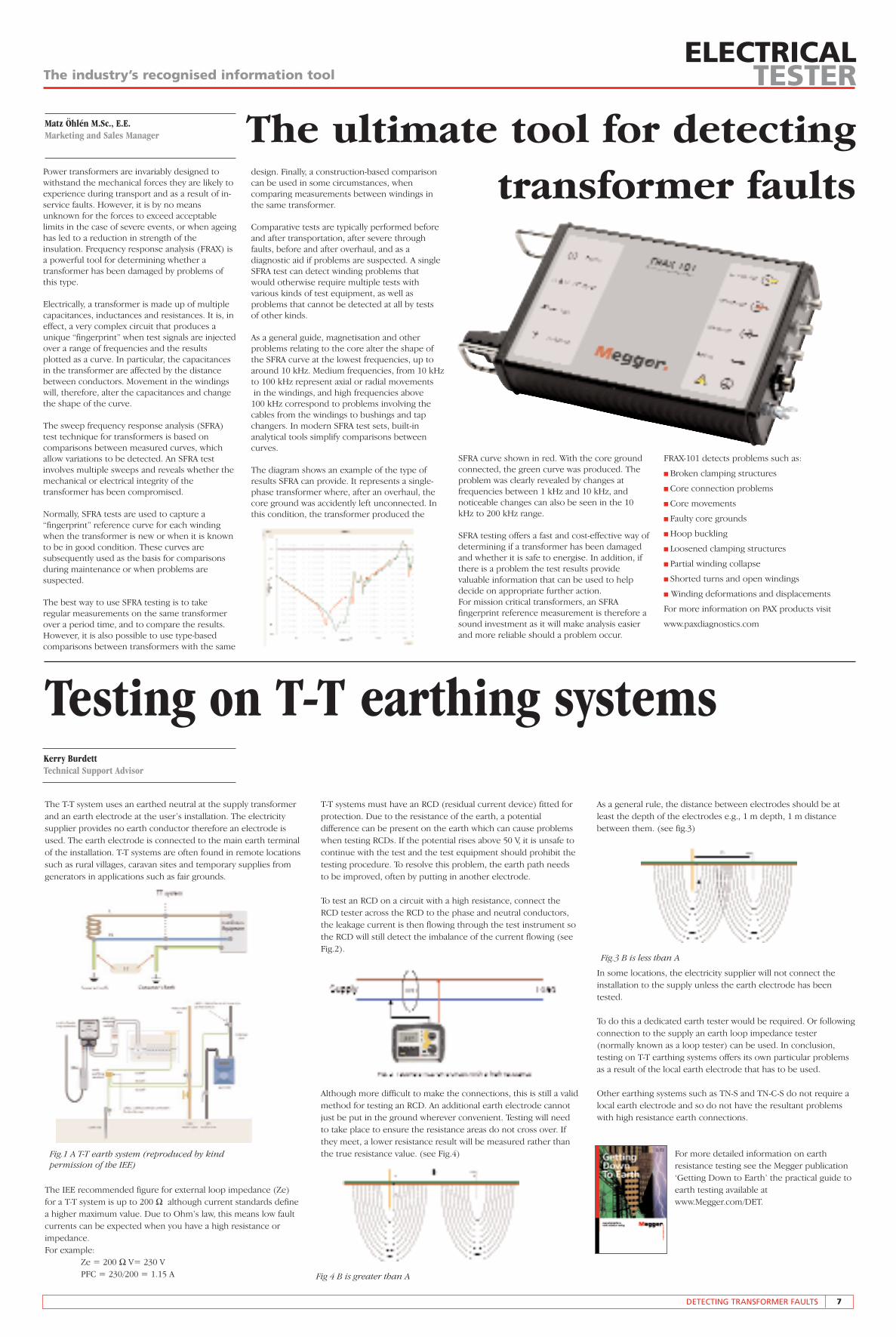
Power transformers are invariably designed towithstand the mechanical forces they are likely toexperience during transport and as a result of in-service faults. However, it is by no meansunknown for the forces to exceed acceptablelimits in the case of severe events, or when ageinghas led to a reduction in strength of theinsulation. Frequency response analysis (FRAX) isa powerful tool for determining whether atransformer has been damaged by problems ofthis type.
Electrically, a transformer is made up of multiplecapacitances, inductances and resistances. It is, ineffect, a very complex circuit that produces aunique “fingerprint” when test signals are injectedover a range of frequencies and the resultsplotted as a curve. In particular, the capacitancesin the transformer are affected by the distancebetween conductors. Movement in the windingswill, therefore, alter the capacitances and changethe shape of the curve.
The sweep frequency response analysis (SFRA)test technique for transformers is based oncomparisons between measured curves, whichallow variations to be detected. An SFRA testinvolves multiple sweeps and reveals whether themechanical or electrical integrity of thetransformer has been compromised.
Normally, SFRA tests are used to capture a“fingerprint” reference curve for each windingwhen the transformer is new or when it is knownto be in good condition. These curves aresubsequently used as the basis for comparisonsduring maintenance or when problems aresuspected.
The best way to use SFRA testing is to takeregular measurements on the same transformerover a period time, and to compare the results.However, it is also possible to use type-basedcomparisons between transformers with the same
The ultimate tool for detectingtransformer faults
design. Finally, a construction-based comparisoncan be used in some circumstances, whencomparing measurements between windings inthe same transformer.
Comparative tests are typically performed beforeand after transportation, after severe throughfaults, before and after overhaul, and as adiagnostic aid if problems are suspected. A singleSFRA test can detect winding problems thatwould otherwise require multiple tests withvarious kinds of test equipment, as well asproblems that cannot be detected at all by tests of other kinds.
As a general guide, magnetisation and otherproblems relating to the core alter the shape ofthe SFRA curve at the lowest frequencies, up toaround 10 kHz. Medium frequencies, from 10 kHzto 100 kHz represent axial or radial movementsin the windings, and high frequencies above
100 kHz correspond to problems involving thecables from the windings to bushings and tapchangers. In modern SFRA test sets, built-inanalytical tools simplify comparisons betweencurves.
The diagram shows an example of the type ofresults SFRA can provide. It represents a single-phase transformer where, after an overhaul, thecore ground was accidently left unconnected. Inthis condition, the transformer produced the
SFRA curve shown in red. With the core groundconnected, the green curve was produced. Theproblem was clearly revealed by changes atfrequencies between 1 kHz and 10 kHz, andnoticeable changes can also be seen in the 10kHz to 200 kHz range.
SFRA testing offers a fast and cost-effective way ofdetermining if a transformer has been damagedand whether it is safe to energise. In addition, ifthere is a problem the test results providevaluable information that can be used to helpdecide on appropriate further action. For mission critical transformers, an SFRAfingerprint reference measurement is therefore asound investment as it will make analysis easierand more reliable should a problem occur.
FRAX-101 detects problems such as:
n Broken clamping structures
n Core connection problems
n Core movements
n Faulty core grounds
n Hoop buckling
n Loosened clamping structures
n Partial winding collapse
n Shorted turns and open windings
n Winding deformations and displacements
For more information on PAX products visit
www.paxdiagnostics.com
Testing on T-T earthing systemsKerry BurdettTechnical Support Advisor
The T-T system uses an earthed neutral at the supply transformerand an earth electrode at the user’s installation. The electricitysupplier provides no earth conductor therefore an electrode isused. The earth electrode is connected to the main earth terminalof the installation. T-T systems are often found in remote locationssuch as rural villages, caravan sites and temporary supplies fromgenerators in applications such as fair grounds.
The IEE recommended figure for external loop impedance (Ze) for a T-T system is up to 200 Ω although current standards definea higher maximum value. Due to Ohm’s law, this means low faultcurrents can be expected when you have a high resistance orimpedance.For example:
Ze = 200 Ω V= 230 VPFC = 230/200 = 1.15 A
T-T systems must have an RCD (residual current device) fitted forprotection. Due to the resistance of the earth, a potentialdifference can be present on the earth which can cause problemswhen testing RCDs. If the potential rises above 50 V, it is unsafe tocontinue with the test and the test equipment should prohibit thetesting procedure. To resolve this problem, the earth path needsto be improved, often by putting in another electrode.
To test an RCD on a circuit with a high resistance, connect theRCD tester across the RCD to the phase and neutral conductors,the leakage current is then flowing through the test instrument sothe RCD will still detect the imbalance of the current flowing (seeFig.2).
Although more difficult to make the connections, this is still a validmethod for testing an RCD. An additional earth electrode cannotjust be put in the ground wherever convenient. Testing will needto take place to ensure the resistance areas do not cross over. Ifthey meet, a lower resistance result will be measured rather thanthe true resistance value. (see Fig.4)
As a general rule, the distance between electrodes should be atleast the depth of the electrodes e.g., 1 m depth, 1 m distancebetween them. (see fig.3)
In some locations, the electricity supplier will not connect theinstallation to the supply unless the earth electrode has beentested.
To do this a dedicated earth tester would be required. Or followingconnection to the supply an earth loop impedance tester(normally known as a loop tester) can be used. In conclusion,testing on T-T earthing systems offers its own particular problemsas a result of the local earth electrode that has to be used.
Other earthing systems such as TN-S and TN-C-S do not require alocal earth electrode and so do not have the resultant problemswith high resistance earth connections.
For more detailed information on earthresistance testing see the Megger publication‘Getting Down to Earth’ the practical guide toearth testing available atwww.Megger.com/DET.
Fig.1 A T-T earth system (reproduced by kindpermission of the IEE)
Fig.3 B is less than A
Fig 4 B is greater than A
ELECTRICALTESTERThe industry’s recognised information tool
8 TRAINING UPDATE
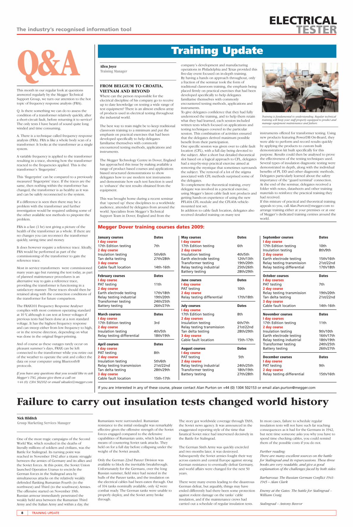
Q&AFROM BELGIUM TO CROATIA,VIETNAM AND BEYONDWhere can the person responsible for theelectrical discipline of his company go to receiveup to date knowledge on testing a wide range oftest equipment? There is an almost endless arrayof products used in electrical testing throughoutthe industrial world.
The best way to train might be to keep traditionalclassroom training to a minimum and put theemphasis on practical exercises that had beendeveloped specifically to help delegatesfamiliarise themselves with commonlyencountered testing methods, applications andinstruments.
The Megger Technology Centre in Dover, Englandhas approached this issue by making available arange of product based courses and applicationsbiased structured demonstrations to showdelegates how to use modern test instrumentsand demonstrate how each test function is usedto ‘enhance’ the test results obtained from theequipment.
This was brought home during a recent seminarthat ‘opened up’ these disciplines to a worldwideaudience, attended by delegates from around theworld. Specialists from Megger’s TechnicalSupport Team in Dover, England and from the
company’s development and manufacturingoperations in Philadelphia and Texas provided thisfive-day event focused on in-depth training.By having a hands on approach throughout, onlya fraction of the seminar took the form oftraditional classroom training, the emphasis beingplaced firmly on practical exercises that had beendeveloped specifically to help delegatesfamiliarise themselves with commonlyencountered testing methods, applications andinstruments.To give delegates confidence that they had fullyunderstood the training, and to help them retainwhat they had learned, each session includedwritten tests which focused on applications andtesting techniques covered in the particularsession. This combination of activities ensuredthat the delegates derived maximum possiblebenefit from their participation.One specific session was given over to cable faultlocation (CFL), with a full day being devoted tothe subject. After a short but detailed theoreticalslot based on a logical approach to CFL, delegateshad a step-by-step practical exercise aimed atremoving the mystique that sometimes surroundsthe subject. The removal of a lot of the stigmaassociated with CFL methods surprised some ofthe delegates.To complement the theoretical training, everydelegate was involved in a practical exercise,using Megger’s latest cable fault test products andgetting hands-on experience of using the newPFL40A CFL module and the CFL40A vehicle-mounted test set.In addition to cable fault location, delegates alsoreceived detailed training on many test
Nick HilditchGroup Marketing Services Manager
Allen JoyceTraining Manager
This month in our regular look at questionsanswered regularly by the Megger TechnicalSupport Group, we turn our attention to the hottopic of frequency response analysis (FRA).
Q. Is there something we can do to assess thecondition of a transformer relatively quickly, aftera short-circuit fault, before returning it to service?The only tests I have heard of sound quite longwinded and time consuming.
A. There is a technique called frequency responseanalysis (FRA). FRA is like a whole body scan of atransformer. It looks at the transformer as a singlesystem.
A variable frequency is applied to the transformerresulting in a trace, showing how the transformerreacted to the frequencies applied. This is thetransformer’s ‘fingerprint’.
This ‘fingerprint’ can be compared to a previouslymeasured ‘fingerprint’ trace. If the traces are thesame, then nothing within the transformer haschanged, the transformer is as healthy as it wasand can be safely reconnected to the system.
If a difference is seen then there may be aproblem with the transformer and furtherinvestigation would be required utilising some ofthe other available test methods to pinpoint theproblem.
FRA is a fast (1 hr) test giving a picture of thehealth of the transformer as a whole. If there areno changes you can reconnect the transformerquickly, saving time and money.
It does however require a reference trace. Ideally,FRA would be performed as part of thecommissioning of the transformer to gain thereference trace.
Most in service transformers were commissionedmany years ago but running the test today, as partof planned maintenance procedures is analternative way to gain a reference trace,providing the transformer is functioning in asatisfactory manner. These traces should then beretained along with the connection conditions ofthe transformer for future comparison.
The FRAX101 Frequency Response Analysercomplies with most common operating standardat 10 V, although it can test at lower voltages ifprevious tests had been done at a non standardvoltage. It has the highest frequency responseand can sweep either from low frequency to high,or in the reverse direction, depending on whatwas done in the original finger-printing.
And of course as these outages rarely occur onpleasant summer’s days, FRAX can be leftconnected to the transformer while you retire outof the weather to operate the unit and collect thedata on your computer using Bluetooth®protocols.
If you have any questions that you would like to askMegger’s TSG, please give them a call on +44 (0) 1304 502102 or email [email protected]
Training Update
instruments offered for transformer testing. Usingnew products featuring PowerDB On-Board, theywere able to perform and record results quicklyby applying the products to custom builtdemonstration kit built specifically for thispurpose. Results could then be analysed to provethe effectiveness of the testing techniques used.Several types of insulation diagnostic testing weredemonstrated in depth, along with the individualbenefits of PI, DD and other diagnostic methods.Delegates particularly learned about the safetyimportance of the “guard terminal’ connection.At the end of the seminar, delegates received afolder with notes, datasheets and other trainingmaterials to reinforce the practical training theyhad received. If this mixture of practical and theoretical trainingappeals to you, call [email protected] toarrange training either at your premises or at oneof Megger’s dedicated training centres around theworld.
Failure to carry out insulation tests changed world history
Rumanians were surrounded. Rumanianresistance to the initial onslaught was remarkablyeffective given the offensive strength of the Sovietforces engaged compared to the defensivecapabilities of Rumanian units, which lacked anymeans of countering Soviet tank attacks. Theyheld on for a full day before collapsing under theweight of the Soviet assault.
Only the German 22nd Panzer Division wasavailable to block the inevitable breakthrough.Unfortunately for the Germans, over the longRussian summer, field mice had nested in thehulls of the Panzer tanks, and the insulation onthe electrical cables had been eaten through. Outof 104 tanks nominally available, only 42 werecombat ready. The German tanks were unable toproperly deploy, and the Soviet army brokethrough.
One of the most tragic campaigns of the SecondWorld War, which resulted in the deaths ofliterally millions of soldiers and civilians, was theBattle for Stalingrad. Its turning point wasreached in November 1942 after a titanic strugglebetween the armies of Germany and its allies andthe Soviet forces. At this point, the Soviet Unionlaunched Operation Uranus to encircle theGerman forces in the Stalingrad area bysimultaneous attacks on the relatively weaklydefended flanking Rumanian Fourth (to thenorthwest) and Third (to the southwest) Armies.The offensive started on November 19th.Russian armour immediately penetrated theweakly held area between the Rumanian ThirdArmy and the Italian Army and within a day, the
The story got worldwide coverage through TASS,the Soviet news agency. It was announced in theexaggerated reporting style of the time thatfanatical Soviet mice had intervened decisively inthe Battle for Stalingrad.
The German Sixth Army was quickly encircledand two months later, it was destroyed.Subsequently the Soviet armies fought their wayacross eastern and central Europe against strongGerman resistance to eventually defeat Germany,and world affairs were changed for the next 50years.
There were many events leading to the disastrousGerman defeat, but arguably, things may haveended differently had there been some protectionagainst rodent damage on the tanks’ cableinsulation, and if the maintenance crews hadcarried out a schedule of regular insulation tests.
Training is fundamental to understanding. Regular technicaltraining will keep your staff properly equipped to predict andmanage equipment maintenance and failure.
Megger Dover training courses dates 2009:
In most cases, failure to schedule regularinsulation tests will not have such far reachingconsequences as it had for the Germans in 1942,but next time someone asks you why you have tospend time checking cables, you could remindthem of the possible costs if you do not.
Further reading:There are many excellent sources on the battlefor Stalingrad and its repurcussions. These threebooks are very readable, and give a goodexplanation of the challenges faced by both sides:
Barbarossa: The Russian German Conflict 1941-1945 – Alan Clark
Enemy at the Gates: The battle for Stalingrad –William Craig
Stalingrad – Antony Beevor
If you are interested in any of these course, please contact Alan Purton on +44 (0) 1304 502153 or email [email protected]
January courses DatesI day course 17th Edition testing 7th2 day courseInsulation testing 5th/6thTan delta testing 27th/28th3 day courseCable fault location 14th-16th
February courses DatesI day course PAT testing 11th2 day courseEarth electrode testing 17th/18thRelay testing industrial 19th/20thTransformer testing 24th/25thBattery testing 26th/27th
March courses DatesI day course 17th Edition testing 3rd2 day courseInsulation testing 4th/5thRelay testing differential 18th/19th
April courses DatesI day course PAT testing 8th2 day courseInsulation testing 5th/6thRelay testing transmission 21st/22ndTan delta testing 28th/29th3 day courseCable fault location 15th-17th
May courses DatesI day course 17th Edition testing 6th2 day courseInsulation testing 4th/5thEarth electrode testing 12th/13thTransformer testing 19th/20thRelay testing industrial 25th/26thBattery testing 28th/29th
June courses DatesI day course PAT testing 10th2 day courseRelay testing differential 17th/18th
July courses DatesI day course 17th Edition testing 8th2 day coursesInsulation testing 6th/7thRelay testing transmission 21st/22ndTan delta testing 28th/29th3 day courseCable fault location 15th-17th
August courses DatesI day course PAT testing 5th2 day courseRelay testing industrial 24th/25thTransformer testing 18th/19thBattery testing 27th/28th
September courses DatesI day course17th Edition testing 10thInsulation testing 8th/9th2 day courseEarth electrode testing 15th/16thRelay testing transmission 21st/22ndRelay testing differential 17th/18th
October courses DatesI day courses PAT testing 7th 2 day courseRelay testing transmission 19th/20thTan delta testing 21st/22nd3 day courseCable fault location 14th-16th
November courses DatesI day courses 17th Edition testing 11th 2 day courseInsulation testing 9th/10thEarth electrode testing 16th/17thRelay testing industrial 18th/19thTransformer testing 24th/25thBattery testing 26th/27th
December courses DatesI day coursePAT testing 9th 2 day courseRelay testing differential 15th/16th