Embed Size (px)
Citation preview

University of North DakotaUND Scholarly Commons
Theses and Dissertations Theses, Dissertations, and Senior Projects
1988
Sedimentology and Stratigraphy of Glacial LakeSouris, North Dakota: effects of a glacial-lakeoutburstMark L. LordUniversity of North Dakota
Follow this and additional works at: https://commons.und.edu/theses
Part of the Geology Commons
This Dissertation is brought to you for free and open access by the Theses, Dissertations, and Senior Projects at UND Scholarly Commons. It has beenaccepted for inclusion in Theses and Dissertations by an authorized administrator of UND Scholarly Commons. For more information, please [email protected].
Recommended CitationLord, Mark L., "Sedimentology and Stratigraphy of Glacial Lake Souris, North Dakota: effects of a glacial-lake outburst" (1988). Thesesand Dissertations. 183.https://commons.und.edu/theses/183

l I
SEDIMENTOLOGY AND STRATIGRAPHY OF GLACIAL LAKE SOURIS,
NORTH DAKOTA: EFFECTS OF A GLACIAL-LAKE OUTBURST
by
Mark L. Lord
Bachelor of Science, State University of
New York College at Cortland, 1981
Master of Science
University of North Dakota, 1984
A Dissertation
Submitted to the Graduate Faculty
of the
University of North Dakota
in partial fulfillment of the requirements
for the degree of
Doctor of Philosophy
Grand Forks, North Dakota
August
1988

This Dissertation submitted by Mark L. Lord in partial fulfillment of the requirements for the Degree of Doctor of Philosophy from the University of North Dakota has been read by the Faculty Advisory Committee under whom the work has been done, and is hereby approved.
(Chairperson)
This Dissertation meets the standards for appearance and conforms to the style and format requirements of the Graduate School of the University of North Dakota, and is hereby approved.
Dean of the Graduate School
ii
I t
Permission
Title Sedimentology and Stratigraphy of Glacial Lake Souris, North
Dakota: Effects of a Glacial-Lake Outburst
Department Geology and Geological Engineering
Degree Doctor of Philosophy
In presenting this dissertation in partial fulfillment of the requirements for a graduate degree from the University of North Dakota, I agree that the library of this University ·shall make it freely available for inspection. I further agree that permission for extensive copying for scholarly purposes may be granted by the professor who supervised my dissertation work or, in his absence, by the Chairman of the Department or the Dean of the Graduate School. It is understood that any copying or publication or other use of this dissertation or part thereof for financial gain shall not be allowed without my written permission. It is also understood that due recognition shall be given to me and to the University of North Dakota in any scholarly use which may be made of any material in my dissertation.
iii
Signature ~~-+-~-·:_.~~-'-~...:.;_ . ..,__,'---c..::..-"'-~
Date ~----'-~.J..~=:..,'Ci'-11-__:;::__:___01-! _,_(--'--C/~:?':~15'~
·._, . ...,.._, .

TABLE OF CONTENTS
LIST OF ILLUSTRATIONS .•.•..•••••..•.•..................•........... vi
LIST OF TABLES ........••••.•.................•••..•....••..•.•..•.• ix
ACKNOWLEDGMENTS .....••••••...•................•.•••.•••.•.....•..... x
ABSTRACT .••.........•••..••...•••...........•.........•••..•.•••... Xi
INTRODUCTION •...........••••..•.•...............•.•.••••••...•....•. 1 General Background ..•.•...............•...........••....•••.... 1 Objectives ....••.•...•.......••...............................• 2 Geologic Setting .................•.......................•..... 3
Area of Study Regional Geology Glacial Lake Souris
Introduction Origin and Drainage History Sediments Geomorphology
The Lake Regina Outburst: Implications for Lake Souris
METHODS OF STUDY •.......•.........•........••••••......••.....•.... 24 Sediment Collection and Analysis ....••.•.......•..••....•••••• 24
Preliminary Work Drilling Laboratory Work
Mapp.in, the Lake Souris Plain Area ............................ 29 Anal yt cal Methods .•.....•..••................................ 30
LITHOFACIES AND STRATIGRAPHY .....•••.......•......•................ 34 Description of Lithofacies .••.•............................... 34
Introduction Diamicton Lithofacies Laminated Silt and Clay Lithofacies Matrix-rich Gravel Lithofacies Matrix-deficient Gravel Lithofacies Sand Lithofacies
Description of Stratigraphy ••••..•••..•.•...•................. 44 Purpose Occurrence Vertical and Lateral Lithofacies Relations
Interpretation ...•..•....•.••••••...•••••••.••••••••.......... 56 Introduction Diamicton Lithofacies Laminated Silt and Clay Lithofacies Matrix-rich Gravel Lithofacies Matrix-deficient Gravel Lithofacies Sand Lithofacies Development of Lithofacies Sequences
iv
SEDIMENTOLOGY AND DEVELOPMENT OF OUTBURST SEDIMENTS •••••.••...•...• 65 Introduction •..........•..•......•.....•.••..•..••.•.•..••...• 65 Textural Description ..••.••.............•.....•.••.•••.•••..•• 65 Pre-outburst and Post-outburst Setting of Lake Souris ...•..... 85 0 i scuss ion of Oepos it ion a 1 Processes ....................•..... 99
Introduction Braided Rivers Sediment Gravity Flows Summary
Discussion of Fan Development. .••••..•......••.•...•........• 111 Introduction Vertical Sequences Areal Trends and Paleoflow Conditions Depositional Model
GEOMORPHOLOGIC EFFECTS OF THE OUTBURST .•..............•••..•...... 132
FURTHER STUDY AND IMPLICATIONS .•....•.....•.••.••..••.....•••..•.. 137
SUMMARY AND CONCLUSIONS ....•.•......•..••......•..........•....•.. 140
APPENDICES ................•••.•...•..••••••••••••.....•........... 144 Appendix A: Locations and descriptions of samples
collected for study ••..••••....•...•.••....•••.•••..•... 145 Appendix B: Phi values of sediment sample
textural statistics ••••.•....••..........•.............. 166 Appendix C: Percentages of sediments within one-quarter phi
coarser than indicated phi size for samples analyzed •... 172 Appendix D: Surface geology of the Souris River Map Area,
North Dakota ••.......••......••••..••....•.......•...... 191
REFERENCES C !TED ......•...........•..•.•....•....................• 192
V

LIST OF ILLUSTRATIONS
Figure
1. Location of Glacial Lake Souris and regional physiographic features ••..••.....••••••.•••....•••..•.......... 4
2. Regional glacial lakes and glacial-lake spillways related to Glacial Lake Souris ......•......•••.••.•...•.........••••..• ?
3. Location of the Martin ice margin and outlets of Glacial Lake Souris •..................•..•••....•......••.....•••.•••• 11
4. General geologic map of Glacial Lake Souris ......•.....••....• 15
5. Abandoned Pleistocene channels related to Lake Souris ..••..... 19
6. Location of samples holes drilled for this study .•....•••...•. 26
7. Location of Souris River Map Area ..•........••••........•..•.. 31
8. Sediment sample of diamicton l ithofacies ...................... 36
9. Sediment sample of laminated silt and clay lithofacies .•••.... 36
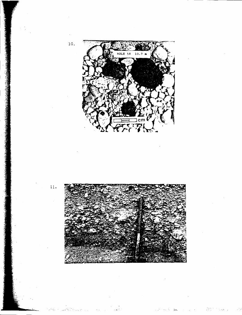
10. Sediment sample of matrix-rich gravel lithofacies; note presence of lignite clasts .•....•...•.••.•••••••....•••.•..... 39
11. Exposure of matrix-deficient gravel lithofacies •••......•..•.. 39
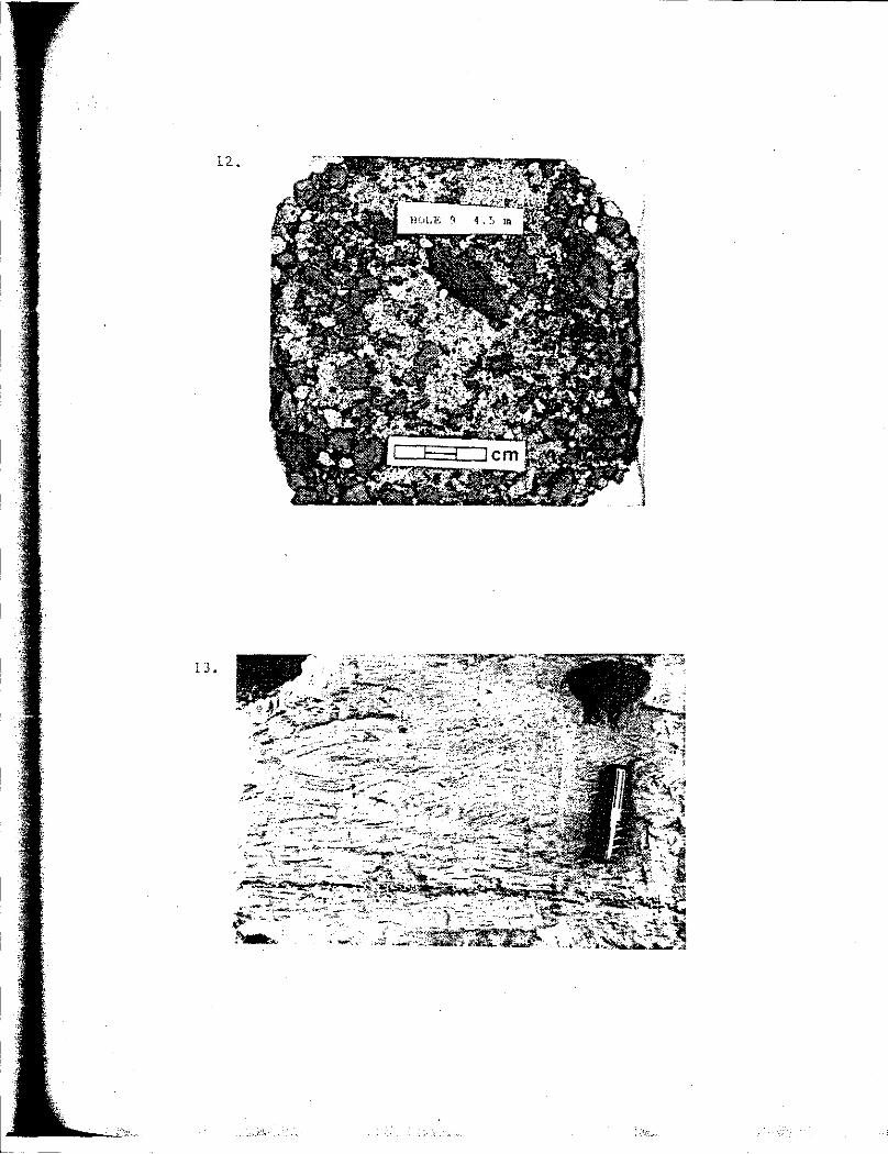
12. Sediment sample of sand lithofacies with abundant outsize 1 ignite clasts ................................................ 42
13. Exposure of sand lithofacies exhibiting climbing ripple cross-1 ami nat i ans ..••.....•.........••••.••..•..•..•.......... 42
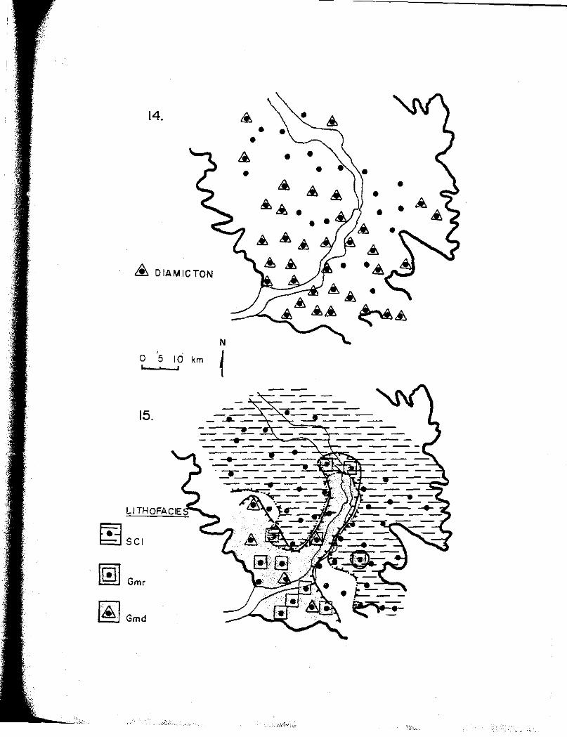
14. Location of holes where diamicton lithofacies is present ...... 46
15. Location of holes where lithofacies SCl, Gmr, and Gmd are present. •.••..•......•••••••.••..•........................ 46
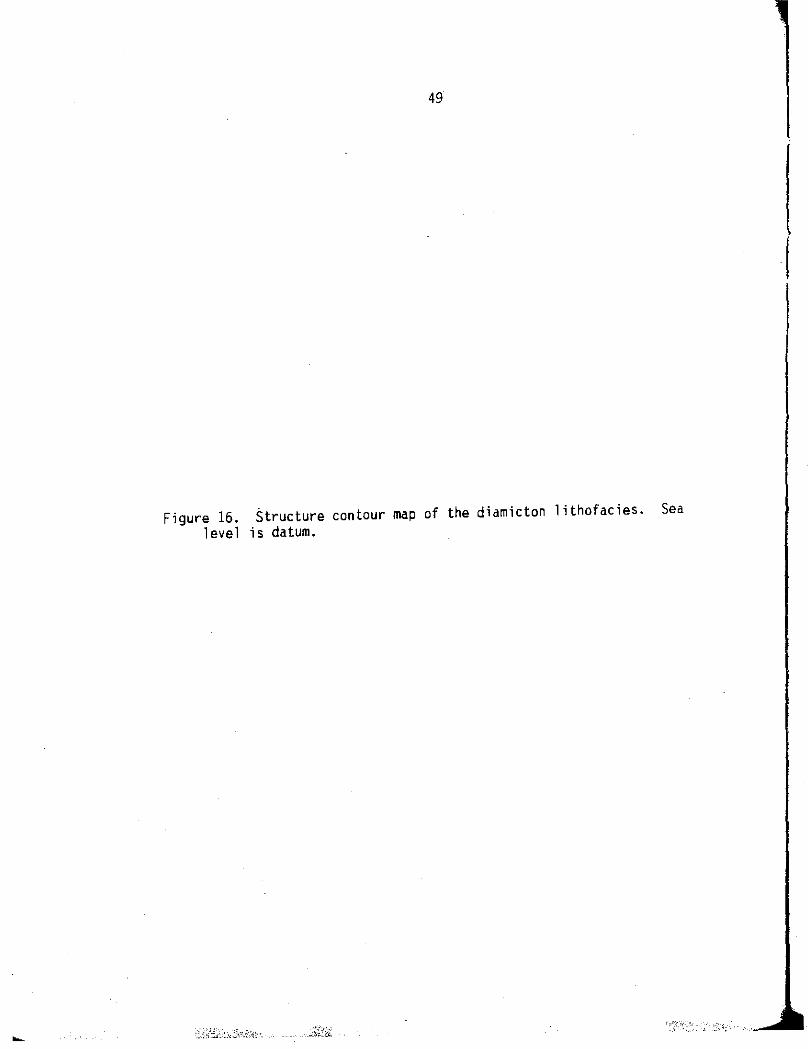
16. Structure contour map of the diamicton lithofacies ............ 49
17. Geologic cross section of the Lake Souris basin sediments oriented parallel to the Souris River ...•..•.........•........ 52
18. Geologic cross section of the Lake Souris basin sediments oriented perpendicular to the Souris River .....••......••.•... 54
19. Histograms of 5 textural parameters for all samples; n=l69 •..• 67
v.i
20. Cross-plots of a) sorting versus mean, and b) coarsest one percent versus median; n=l69 •.••....•.••.••.............•. 69
21. Individual and cumulative frequency grain size curves for representative samples of a) sand lithofacies, b) matrix-rich gravel lithofacies, and c) matrix-deficient l ithofacies ••...•••.•.•.••...••••••.......•.••••.•••••••..•••• 71
22. Selected plots of depth versus textural parameter values for a) a homogeneous section, b) a section with a coarse-grained spike at the bottom of the outburst sediments .••.••.••........ 74
23. Selected plots of depth versus textural parameter values for a) a coarsening upward section, and b) an irregular section ... 76
24. Cross section, oriented parallel to the Souris River, showing mean grain size of outburst-deposited sediments .•............. 78
25. Contour maps of textural parameter values averaged for each hole. Values of the coarse-grained spikes at the bottom of holes are not included in the averaged values ..•.... 81
26. Trend surfaces significant to the 97.5 percent level. a) Third order surface of averaged mean grain size; explained variation= 67 percent (see Fig. 25a). b) First order surface of averaged coarsest one percent; explained variation = 23 percent (see Fig. 25b) ......................... 83
27. Contour map of textural parameter values. a) Averaged mean grain size minus mean grain size of bottom outburst sample; positive values indicate fining upward. b) Averaged sorting minus sorting of bottom outburst sample; positive values indicate sediments become more poorly sorted upward .•.. 86
28. Regional topographic profile showing glacial lakes, spillway valley bottoms, and high-water marks of the Lake Regina outburst flows ..............•..................... 88
29. Contour map of the probable water depths in Glacial Lake Souris prior to inundation by the outburst flows .........•.... 91
30. Isopach map of the outburst-deposited sediments in the Lake Souris basin ••........................................... 91
31. Detailed structural cross section of the southern fan parallel to the Souris River .................................. 93
32. Topographic profiles made perpendicular to the Souris spillway from the Lake Souris inlet area to the outlet area ..• 95
33. Longitudinal topographic profile of the Souris spillway through Lake Souris ••..••••••••.•••••...........•....•••..•... 97
Vii
.;..~- ;

34. Selected elevations (in metres) on braided river gravel depo~its at the Lake Souris inlet •.•.•......••...••••••.....• 101
35. Individual and cumulative frequency grain-size curves of a) a sand sample with outsize lignite clast present (skewness= -2.50), and b) a sand sample without outsize lignite present (skewness= 0.05) ............................ 108
36. Textural data (hole 42) for a fining upward succession interrupted by deposition from a high-density flow .•.••..•... 116
37. Contour map of paleovelocities in Lake Souris based upon the application of equations 3 and 4 to the averaged coarsest one percent textural data ...........•........••••... 121
38. Generalized distribution of deposits by the three depositional processes listed. The boundaries are drawn based on the presence of the given deposit type and the Lake Souris geologic map ..................................... 125
39. Diagrammatic longitudinal section through the Lake Souris basin depicting relationships of sediments deposited by different deposit ion a 1 processes ............................. 129
40. Diagrammatic model of incision migration by the Souris spillway into the Lake Souris basin in response to falling "lake level ........................................... 134
viii

LIST OF TABLES
1. Comparison of textures and volumes of material eroded versus redeposited, within the Souris and Des lacs spillways, by the Glacial Lake Regina outburst •......•••.••.•...••.....•... , ..•. 22
2. Frequency of vertical transitions between lithofacies ..•..•..• 51
3. Phi values of sediment sample textural statistics .••..••••••. 166
4. Percentages of sediments within one-quarter phi coarser than indicated phi size for all samples analyzed ..........••• 172
ix

ACKNOWLEDGMENTS
My geology faculty advisory committee, Dr. Alan E. Kehew (Chair),
Dr. John R. Reid, Dr. Richard D. Lefever, and Dr. Kenneth L. Harris,
have been of great value in the completion of this dissertation. All
were patient, cooperative, good advisors and friends, and contributed
to the ideas put forth in this dissertation as well as my general
education. Dr. Alan Kehew deserves special thanks; he has been a good
friend and mentor. The help of Dr. Elliot L. Shubert, the outside
member of my advisory committee, is also acknowledged.
Several organizations have provided valuable support that led to
the completion of this project. Most important has been the North
Dakota Geological Survey; under the direction of Mr. Sidney Anderson,
they have provided research support, a drilling rig, drillers (Gary
Stefanovsky, navid Lechner, and Jim Cron), and a valuable opportunity
to cooperate on a Survey mapping project led by Dr. Ken Harris. Dr.
John P. Bluemle was of assistance in providing ideas on the general
geology of the Lake Souris Plain region. Mr. Arden Mathison, of the
U.S. Bureau of Reclamation, provided valuable data on sediments from
the Lake Souris Plain. The University of North Dakota Graduate School
is acknowledged for providing research support and two summer doctoral
fellowships.
My family, including my parents and especially my wife, Patty,
have been very supportive of my education; it has been much
appreciated. I apologize to my wife and child, Joshua, for the
valuable time I have missed with them during the completion of this
degree; the time missed has not been for lack of caring.
X
ABSTRACT
Glacial-lake outbursts commonly occurred along the southern
margin of the Laurentide Ice Sheet as ice-marginal lakes suddenly
drained. These outbursts released huge volumes of water with
tremendous erosive potential, forming large trench-shape channels.
Although glacial-lake spillways have been studied in detail, the
effects of outbursts on downstream lakes have not. The purpose of
this study was to demonstrate the effects of the Glacial Lake Regina
outburst on the lake that received the flows, Glacial Lake Souris.
Glacial Lake Souris, located in what is now North Dakota, was
inundated by about 74 km3 of water carrying 25 km3 of sediment from
the outburst of Lake Regina (Saskatchewan). Prior to the outburst,
the bottom of Lake Souris was irregular with two shallow depressions
and comprised of diamicton overlain by silt and clay rhythmites.
Quiet-water lake sedimentation was abruptly halted by coarse-grained
outburst sedimentation.
Based on surficial mapping, subsurface sample collection, and
textural analyses, the outburst sediments have been grouped into three
lithofacies: 1) matrix-rich gravel, commonly with lignite, that
generally occurs at the base of the outburst sediments; 2) matrix
deficient gravel, generally without lignite, that occurs near the
ground surface adjacent to the Souris spillway; and 3) sand, the most
widespread lithofacies, that tends to overlie other lithofacies.
Lignite particles are abundant in much of the sand; at depth, outsize
lignite clasts are common.
xi

I
Three major depositional processes probably are responsible for
deposition of the outburst sediments: braided rivers, low-density
turbidity currents (the dominant process), and high-density turbidity
currents or modified grain flows. Most high-density flows resulted
directly from the influx of the outburst or from continuous
avalanching due to rapid sedimentation. Low-density turbidity
currents occurred for the entire duration of the outburst and were
caused by the continuous influx of sediment-laden flows and by
residual currents from high-density flows.
The emptying of Lake Souris was triggered by inundation of the
lake by outburst waters before silt- and clay-size sediment had time
to settle out. Incision of the lake bottom by outburst flows occurred
concurrently with falling lake level.
Xii
INTRODUCTION
General Background
This study is concerned with the effects of a glacial-lake
outburst on the lake that received the outburst discharges, Glacial
Lake Souris. During the late Wisconsinan, proglacial lakes formed
along the southern margin of the Laurentide Ice Sheet as meltwater
ponded in topographic lows, isostatic depressions, and basins bounded
by ice-marginal deposits. Whereas the existence of such lakes has
long been recognized (Upham, 1896), much new insight has been gained
over the last decade on the development, stability, chronology, and
drainage of glacial lakes in the mid-continent region (Teller and
Clayton, 198}; Karrow and Calkin, 1985; Kehew and Lord, 1986, 1987).
Part of the increased understanding has resulted from the recognition
that many of the ice and/or debris dams of such proglacial lakes
failed suddenly and released huge water volumes (Kehew and Lord,
1987).
Several aspects related to such glacial-lake outbursts have been
studied in detail. For example, the geomorphology of glacial-lake
spillways, the paleohydrology of the outburst flows, the sedimentology
of gravel deposits within spillways, and the effects on downstream,
glacial-lake water levels have been discussed by numerous workers for
events within and outside the mid-continent region (Bretz, 1929;
Malde, 1968; Baker, 1973; Kehew, 1982; Clayton, 1983; Kehew and
Clayton, 1983; Teller, 1985; Kehew and Lord, 1986; Lord and Kehew,
1

2
1987). Whereas the general effects of outburst on downstream, glacial
lakes have been studied, detailed investigations of outburst-deposited
sediment in a lake environment are lacking (Kehew and Clayton, 1983).
This study was undertaken in an attempt to narrow this gap in
knowledge and to add to the understanding about the character and
importance of outbursts as a glacial meltwater process, at least along
segments of the margin of the Laurentide Ice Sheet.
Objectives
The foremost objective of this study is to explain the origin and
pattern of deposition of the coarse-grained sediments that cover much
of the Glacial Lake Souris basin floor. Such an explanation must
interrelate a·spects of, and be consistent with, the lithology,
stratigraphy, sedimentology, and geomorphology of the lake plain, as
well as being consistent with the regional geologic framework.
Specific objectives of this study are 1) to describe the
lithofacies present in the Lake Souris basin and their stratigraphic
relationships, 2) to reconstruct the conditions of Lake Souris prior
to the hypothesized inundation of the basin by glacial-lake outburst
flows, 3) to demonstrate the sedimentologic and geomorphic effects of
such an outburst on Lake Souris, and 4) to present a depositional
model for outburst flows into ponded water and discuss the
implications of such a model for analogous areas.
In this study, the regional geologic setting and information
directly pertinent to Glacial Lake Souris are presented first. After
a discussion of methodology used for this study, the lithofacies and

3
stratigraphy of sediments of the Lake Souris basin are then described
and interpreted, It is in this section that the outburst-deposited
sediments are identified and the foundation for documenting the
effects of outburst flows on Lake Souris is established. Detailed
textural information on the glacial-lake outburst sediment deposited
in Lake Souris is given. These data are used to interpret the effects
of the outburst on sedimentation and serve as a basis for developing a
model of deposition for the outburst flows. The conclusions presented
in this study will be used to interpret analogous regions and to
assess the role of outbursts as a glacial-meltwater process.
Geologic Setting
Area of Study·
The Glacial Lake Souris plain is located in north-central North
Dakota and, to a small extent, along the international border in
southwest Manitoba (Fig. 1). This study is concerned primarily with
the coarse-grained sediments of Lake Souris; they occur within an area
bounded by the 48 degree and 48 degree 45 minute parallels, and the
100 degree and 101 degree meridians. The Souris River flows north
through the region of study, bisecting the Lake Souris plain. To the
northeast of the Lake Souris plain are the Turtle Mountains, an
isolated upland region which diverted glacial flow and meltwater paths
during the Pleistocene Epoch.

4
Figure 1. Location of the Lake Souris plain and regional physiographic features.
•

SASK.
·---.. -···-·-NO. DAK.
MINOT
• ..l' 0(/.
~IS'
MAN.
ROLETTE CO. PIERCE CO.
N
1-.::.:::::.:.:...::.::..._-,----'----T---, o .... _1..._0_2_0 km J WARD CO. McHENRY CO. ·1
101° 100°
49°
4go

6
Regional Geology
Glacial Lake Souris was one of several proglacial lakes that
formed along the southwestern margin of the Laurentide Ice Sheet
during the Wisconsinan glaciation. The ages of these lakes, and the
positions of associated ice margins and spillways are discussed by
Clayton and Moran (1982). Pertinent to this study are the lakes and
spillways that were connected to Lake Souris. Glacial Lake Regina
(Fig. 2) drained through the Souris and Des Lacs spillways
(Christiansen, 1956); this spillway system terminates at Lake Souris.
Glacial Lake Arcola, which existed about 75 km north-northwest of .,
where the Souris spillway crosses the international border, also
drained to the south through the Souris spillway. Lake Souris had
outlets to the south and to the north. It first drained to the south
through the Sheyenne and James spillways into Glacial. Lake Dakota;
subsequently, it drained entirely through the Sheyenne spillway into
Glacial Lake Agassiz (Kehew and Clayton, 1983). The final drainage of
Lake Souris occurred to the north through the Souris-Hind spillway
into Glacial Lake Hind. Lake Hind drained through the Pembina
spillway into Lake Agassiz. All of the spillway segments shown on
Figure 2 are attributed to erosion by discharges from glacial-lake
outbursts (Kehew, 1982; Kehew and Clayton, 1983). More detailed
discussions of the chronologic development and origin of these
spillways and glacial lakes are given in Kehew and Clayton (1983) and
Kehew and Lord (1986, 1987).
The textural characteristics and lithology of sediments deposited
in Lake Souris were strongly influenced by the regional geology. Low-
7
Figure 2. Regional glacial lakes and glacial-lake spillways related to Glacial lake Souris.
I ! ! [ !
L

LAKE REGINA
/'-A-- ~
LAKE LAKE AGASSIZ
HIND --"'-"----"-"-
~
S0UR/,s, CANADA
U.S.
LAKE SOURIS -~(
~
N Minmtsota .
~ \~
'
~ "' "' "' ' 0 100 km ;;; I I I ~ ~\ 0 50 Miles "'
~( North Dakota
South Dakota LAKE DAKOTA

9
relief, hummocky, glacial collapse topography predominates over most
of the region shown in Figure 2 (Christiansen, 1956; Clayton, 1980).
Glacial-drift thicknesses range from a few metres to about 60 m.
High-relief, glacial collapse topography occurs in the Moose
Mountains, located just north of the Lake Arcola plain, and in the
Turtle Mountains to the northeast of the Lake Souris plain (Fig. 1).
Drift thicknesses in these regions reach up to 200 m (Clayton and
others, 1980). Directly beneath the glacial drift are poorly
indurated, fine-grained Paleocene and Cretaceous bedrock formations.
Limited outcrops of bedrock occur along spillway sides and in ice
thrust masses (Lord, 1988).
Glacial Lake Souris
Introduction: It is not the purpose of this study to examine the
entire history of Lake Souris; nonetheless, any interpretations put
forth in this study should consider what has been discussed by
previous workers. The objective of this section, then, is to review
briefly the development and drainage history of Lake Souris to
construct a framework into which later interpretations can be
incorporated.
The first geologic map of the Lake Souris plain was produced by
Upham (1896) in conjunction with his well-known study of Lake Agassiz.
Although he did produce a preliminary map of Lake Souris, his main
interest in Lake Souris was its relationship to Lake Agassiz.
Numerous workers have studied aspects of Lake Souris, but, as with
Upham, the majority has been more interested in its relation to some
10
other topic, especially Lake Agassiz (Elson, 1955; Clayton and others,
1980; Brophy and Bluemle, 1983; Fenton and others, 1983). As a
consequence, there is no complete synthesis of all information
relating to Lake Souris and there are basic inconsistencies between
different studies. Studies that are thorough and relevant to this
study will be incorporated in the summary given below.
Origin and Drainage History: There is no conclusive evidence for
a Glacial Lake Souris prior to the late Wisconsinan; the formation of
such a proglacial lake would have become more likely with each
successive advance because of the topographic changes accompanying
glaciation (Bluemle, 1985). In the early stages of development, Lake
Souris existed as a series of isolated supraglacial and ice-walled
lakes (Moran and Deal, 1970; Deal, 1971). During the late
Wisconsinan, Lake Souris existed at least at two times, separated by a
readvance of ice; informally these lakes have been termed Glacial Lake
Souris I and II (Schnacke, 1982). Lake Souris is first known to have
formed as the Souris Lobe retreated from the Martin ice margin (Fig.
3) (Clayton and others, 1980). It is not known how far to the north
the Souris Lobe receded nor the extent to which Lake Souris spread.
Bluemle (1985) has suggested that Lake Souris I, bounded by ice to the
north, covered portions of Pierce, McHenry, and possibly Bottineau
Counties (Fig. 3). In central Pierce County, Lake Souris I sediment
consists of clayey silt (Schnacke, 1982).
Lake Souris I drained to the southeast through numerous outlets;
these include valleys now occupied by Cranberry Lake, Long Lake,
Girard Lake, Battema Lake, Antelope Lake, and Pagel Lake (Fig. 3)

11
Figure 3. Location of the Martin ice margin and outlets of Glacial Lake Souris (modified from Clayton and others, 1980 and Clayton and Moran, 1982).
l

SASK.
NORTH DAKOTA
WARD CO.
101° 100°
ROLETTE CO. PIERCE CO.
BENSON CO.
~ ,sf~ANBERRY "{ AKE
ABANDONED CHANNELS ~ MAJOR ........._.. MINOR
49°

13
(Schnacke, 1982; Bluemle, 1985; Lord, 1988). Each of these outlets
was used for a short period of time, and, except for the Girard Lake
spillway, range in elevation from 466 to 472 m (Clayton and others,
1980). The Girard Lake spillway (elevation about 457 m) is
hypothesized to have been formed by one or more outbursts from Lake
Souris (Schnacke, 1982; Kehew and Clayton, 1983). Flow from these
events continued through the Sheyenne spillway and possibly the
Heimdal diversion channel, which connects to the James spillway (Fig.
3). Kehew and Clayton (1983) have suggested that two outbursts may
have occurred through the Girard Lake spillway: one that flowed down
the Heimdal diversion into the James spillway (leading to Lake
Dakota), and a later flood that flowed down the Sheyenne spillway
(leading to Lake Agassiz) which is lower in elevation.
A short-lived readvance of the Souris lobe to the Martin ice
margin overrode Lake Souris I and all of its former southeastern
outlets (Clayton and others, 1980; Kehew and Clayton, 1983; Bluemle,
1985). As the Souris Lobe again retreated, lake Souris II formed
along the margins of the glacier and used the lowest outlet, Girard
Lake, as its spillway (Kehew and Clayton, 1983). Unless specified
otherwise, any subsequent reference to Lake Souris refers to Lake
Souris II. At sometime after the Souris Lobe had retreated north of
the international border, flows from the outburst of Lake Regina (Fig.
2) debouched into Lake Souris [Kehew, 1982; Kehew and Clayton, 1983).
The influx of water from the outburst probably triggered a complete
and rapid drainage of Lake Souris through the Souris-Hind spillway
(elevation: 455 m) into Lake Hind (Fig. 2) (Kehew and Clayton, 1983;
14
Kehew and Lord, 1987). During the outburst some water may have flowed
out of Lake Souris through the Girard spillway before the northern
outlet developed, but it was probably minor because the morphology of
the outlet, which was previously overridden by ice, was only slightly
modified (Kehew and Clayton, 1983).
Alternative, more complex histories of Lake Souris, which involve
more glacial advances and retreats, have been proposed by some workers
(Brophy and Bluemle, 1983; Fenton and others, 1983). The focus of
those studies, however, was not directly on Lake Souris and,
consequently, involved some assumptions not justified by the geology
of the Lake Souris area. It also should be noted that Lake Souris has
been mapped as connected to Lake Hind along a narrow strip in the
vicinity of the international border (Elson, 1955; Aggregate Resources
Section, 1980). Kehew and Clayton (1983) stated that such a
connection probably was not in existence at the time when Lake Souris
received the outburst flows from Lake Regina.
Sediments: Sediments of the Lake Souris basin are dominantly
sand with lesser amounts of silt and gravel, and very little clay
(Lemke, 1951, 1960). Much of the sediment in the Lake Souris basin
was deposited by flows of the Lake Regina outburst (Kehew and Clayton,
1983; Kehew and Lord, 1987). A fan-shape deposit of gravel occurs at
the mouth of the Souris spillway; sand and some silt are present
basinward of the fan (Fig. 4) (Clayton, 1980; Bluemle, 1982; Lord,
1988). Lake sediment reaches thicknesses of 30 min the southern
portion of the basin and thins to a few metres in the northern portion
(Bluemle, 1982).

15
Figure 4. General geologic map of Glacial Lake Souris (modified from Lord, 1988; Appendix D) .
l 1

O 10 km
8fjcLAY & SILT
OsAND
r·,::.'jsAND DUNES
~SAND & GRAVEL
1: .;/DIAMICTON
GLACIAL LAKE
SOURIS
100°
4 8°---------l.-

17
Adjacent to the Souris River in Bottineau County, till is present
at the surface, where it is cut by lineations trending roughly
parallel to the river (Fig. 4; Appendix D). Lemke (1960) suggested
that a stagnant block of ice in this area may have prohibited the
accumulation of lake sediments. Alternatively, lake sediments in this
area may have been eroded when Lake Souris drained rapidly to the
north (Bluemle, 1985).
Geomorphology: There are several morphologic features of Lake
Souris that are important in assessing its drainage history: these
include shoreline features, sand dunes, and abandoned channels. Beach
ridges and other shoreline features of Lake Souris are indistinct ar.d
disconnected; thus, correlation is not possible (Lemke, 1951; Moran
and Deal, 1970; Bluemle, 1982, 1985). Most shoreline features occur
along the northeast margin of Lake Souris (Bluemle, 1985; Lord, 1988).
Though correlation of shoreline features has not been possible,
several lake levels have been suggested based on the abundance of
shoreline features at several elevations. The three most prominent
probable strandlines occur at 472 m, 457 m, and 450 m (Lemke, 1960;
Moran and Deal, 1970; Bluemle, 1982). Other possible strandline
levels identified occur at 447, 460, 465, 469, 479, and 484 metres
(Moran and Deal, 1970). The studies of lake levels have not addressed
the possible effects of differential rebound nor the complex history
of the lake in relation to these levels. In spite of these
complications, the prominent strandline elevations may be used as
rough guidelines in the interpretation of drainage history.
Sand dunes cover much of the southern half of the Lake Souris

18
plain (Appendix D) (Lemke, 1960; Bluemle, 1982). In areas where the
dunes have high relief, up to 20 metres, they are longitudinal or
irregular dunes (Lord, 1988). The dunes are thought be developed in
reworked well-sorted, outburst-deposited sediment (Kehew and Clayton,
1983).
Many abandoned channels and channel scars occur within and
adjacent to Lake Souris. All of these channels probably formed during
the 1 ate I, i scons i nan and are therefore related to the history of Lake -~
Souris (Clayton, 1980; Bluemle, 1985; Lord, 1988). A map of these
abandoned channels was made from the channels mapped by Lord (1988)
(Fig. 5). The most prominent channel is the Souris spillway which has
a well-defined trench shape at the inlet to Lake Souris and in the
northern third of the lake basin. The network of anastomosing minor
channels, about 20 km northwest of Verendrye (Fig. 1), probably
carried overflow from the Souris spillway near Minot during the
outburst of glacial Lake Regina (Kehew, 1982). The channel scars
trending parallel to the Souris spillway in the northern third of the
lake plain may have formed as Lake Souris drained rapidly to the north
through the Souris-Hind spillway (Bluemle, 1985).
The Lake Regina outburst: implications for Lake Souris
The characteristics of the outburst from Glacial Lake Regina are
critical to understanding the potential effects of such flows upon
arrival at Lake Souris. Conversely, information gained from studying
the sediments of Lake Souris may be used to evaluate the validity of
hypotheses concerning the characteristics of the outburst flows.
,.
19
Figure 5. Abandoned Pleistocene channels related to Lake Souris (modified from Lord, 1988; Appendix D).
' • t i t
t I
f

JOI 0
----.1
0
N
IOKm ·~
MAJOR ~ CHANNELS ~
MINOR '7°7" CHANNELS
LAKE SOURIS
48°
100°

21
Because an objective of this study is to demonstrate the effects of
the Regina outburst on Lake Souris, the characteristics of the
outburst will be reviewed.
Discharges from the catastrophic drainage of Lake Regina flowed
down the Souris and Des Lacs spillways (Fig. 2) (Kehew, 1982). An
estimated 7.4 x 10¹⁰ m3 of water was released within a few weeks from
that lake (Kehew and Clayton, 1983). The outburst flows had
tremendous erosive power; they carved out the entire Souris spillway
upstream from its confluence with the Moose Mountain spillway. The
Souris spillway, downstream from the confluence, and the Des Lacs
spillway existed prior to the outburst, but were markedly enlarged by
the flows (Kehew, 1982; Lord and Kehew, 1987).
Paleohydraulic calculations for the Regina outburst, based on
channel morphology and maximum particle sizes,
discharges of 5.8 x 10⁴ 5 3 -1 to 8.2 x 10 ms and
11.7 ms-l were achieved (Lord and Kehew, 1987).
indicate that
velocities of 2.9 to
Because the sediments
into which the spillways are eroded are generally poorly consolidated
and fine-grained, and because of the erosive power of the outburst
flows, sediment-water concentrations were high. The outburst flows
probably were hyperconcentrated (flow transitional between clear water
and debris flow), averaging about 20 percent sediment by weight and
possibly reaching 40 percent in some areas {Lord and Kehew, 1987).
Volumetric comparisons between the sediment eroded by the Regina
outburst and that redeposited within the spillways show that only a
small percentage of the material was redeposited within the spillways
(Table 1). These data have important implications for Lake Souris

22
Table 1. Comparison of textures and volumes of material eroded versus redeposited, within the Souris and Des Lacs spillways, by the Glacial Lake Regina outburst (Kehew and Lord, 1987).
Outburst Sediment eroded Sediment deposited Percent from spillways within spillways material
Percent Volu~e Percent Voiu~e redeposited ( km ) ( km ) in spillway
Clay&Silt 67 17.4 2 0.01 0.1 Sand 28 7 .3 17 0.13 1.8 Gravel 5 1.3 81 0.61 46.1
Total 100 26.0 100 0.75 2.9

23
because it received the sediment-charged water; an estimated 25 km3 of
sediment was delivered to Lake Souris by the outburst (Lord, 1987).
In addition, by taking into account the textural characteristics of
the sediment eroded versus redeposited (Table 1), estimates of the
sediment volume can be made of different size fractions potentially
delivered to Lake Souris.
The Lake Regina outburst flow characteristics described above can
be used to help interpret the Lake Souris sediments. For example, the
well-sorted sands in Lake Souris have been classified as underflow
deposits partly because this origin is consistent with the
characteristics of the outburst flows (Kehew and Clayton, 1983).
Preliminary Work
METHODS OF STUDY
Sediment Collection and Analysis
All but a few of the samples collected for this study were
obtained using the North Dakota Geological Survey's truck-mounted
hollow-stem auger. Preliminary work consisted mainly of the selection
of drilling locations. The primary purpose of the drilling was to
obtain a vertical and horizontal sampling of the coarse-grained
sediments of Lake Souris. Several factors were important in deciding
upon drilling locations. Geologic maps of McHenry County by Bluemle
(1982) and Pierce County by Carlson and Freers (1975) were studied to
determine approximate locations of sandy lake sediment 1n the Lake
Souris plain. Topographic maps of the bedrock surface in these same
two reports show the locations of pre-glacial channels; these
locations were avoided when drilling. A preliminary contour map of
depth to till in the study area was constructed, using data from
Randich (1971, 1981), so that approximate sand thicknesses would be
known. In addition to the geologic information, road maps were used
to determine which areas were accessible to the drilling rig. Based
on the above described data, about 70 drilling sites were chosen so
that locations would be approximately evenly spaced over the study
area.
24

25
Drilling
Ori 11 ing for this study was conducted during parts of the summers
of 1985 and 1986. The method of drilling used was to auger downward
at a slow rate of rotation to the desired depth and then pull the
auger directly out of the hole with no rotation. Initially, holes
were drilled to a depth of about 3 mat which time the auger was
pulled out and sampled. The hole was then drilled an additional 3 m
when the auger was pulled out and sampled again. This process was
repeated until the desired drilling depth was reached. This method
tends to minimize potential sample contamination and errors in
assigning depths to samples. The disadvantage to this method is that
it markedly increases the amount of time to drill a hole.
Two exceptions occurred to the method just described. Generally,
after hole depths exceeded about 12 m, holes were drilled in
additional increments of 4.5 m, instead of 3 m, to save time. The
second exception was when drilling became difficult due to hard and/or
rocky sediment. In these situations, the auger commonly had to be
rotated backward some before it could be pulled out of the hole,
thereby permitting some sample movement on the auger flights.
Drilling was continued until either clay or till was reached,
except in locations where drilling became too difficult. The depth of
the sample holes ranged from about 2 m to 28 m and averaged about 10
m. Sixty-one holes were drilled for this study (Fig. 6; Appendix A);
the cumulative length of sediment sampled by augering was about 620 m.
Sediment samples were collected directly from auger flights at about
0.75 m intervals and at noticeable lithologic changes; about 800

Ii......
26
Figure 6. Location of sample holes drilled for this study; detailed locations are given in Appendix A.

IOI 0
--- .....
I .,
LAKE
SOUR IS
0 IOKm
---
46 49 • 47 54 •
• • 45• 43 44 •
•53 • 58. 38•
42 • •36 37 • 39 40 • •
41 • 55 • 3; 56 13 14
• • 5712 •
10 • 4 •
9 • 8
• • •
7 •
II • I • 18 • 2 50 33 • • •
100°
26 • 34 •
28
samples were collected. General lithalagic descriptions were made
farall hales in the field. Information on sample depths, textural
characteristics, and sedimentary structures was recorded.
Laboratory Work
The laboratory work required for this study consisted primarily
of describing all of the samples collected and then completing a
textural analysis on selected samples. All samples collected, except
diamictons, were described for grain size, sorting, dry and wet color
(using the Munsell Soil Color Chart), sedimentary structures,
abundance of lignite, and any other distinguishing characteristics.
As the sediments were befog described, samples were chosen for
textural analyses. Samples from hole sites located in the coarse
grained fan were analyzed for texture; this includes all holes on the
west side of the Souris River (Fig. 6) and the majority of those on
the east side. Samples from individual holes were chosen for textural
analyses at about 1.5 m intervals or at noticeable textural changes,
whichever was less. Only samples composed of silt or coarser sediment
were analyzed. Of the samples collected, 169 were analyzed for
texture; specific information on the samples analyzed may be found 1n
Appendix 8.
Textural characteristics of the sediments were determined using a
settling tube for samples consisting of sand and/or silt. Samples
containing sand and gravel were analyzed by determining the texture of
the sand fraction using the settling tube and of the gravel fraction
using sieves. Sample preparation for the settling tube included

29
several steps. Bulk samples collected from the auger flights, which
had average masses of about 600 g each, were split with a sample
splitter until the mass of the sample was between 15 g and 30 g. To
disaggregate clumps in the sediment, the reduced sample was put into a
beaker, mixed with water, stirred, set several hours, and then dried
in an oven at low temperatures. Each sample was then split several
times until the sample mass was between 0.2 and 0.4 g. The textures
of the sample were then determined using standard settling tube
techniques (Gibbs, 1974). The settling tube used for this procedure
has a drop distance up to about 105 cm and has an inside diameter of
19 cm.
For sand and gravel sediments, the sample was sieved using a -1
phi screen to·split sand from gravel. The texture of the gravel was
determined using standard sieve techniques (Folk, 1980) with screens
at quarter-phi intervals. The texture of the sand was determined
using the settling tube. The results of the textural analyses of the
coarse and fine fractions of the samples were normalized and combined
to obtain complete sediment-size distribution data. Using moment
measures, the textural statistics for all samples were calculated by a
computer program written by Lefever (1986a).
Mapping.The Lake Souris Plain Area
An objective of this study was to construct a map of the coarse
grained sediments of Lake Souris. Such an area, the Souris River Map
Area, was mapped (Lord, 1988) in conjunction with a project for the
North Dakota Geological Survey. The size and boundaries of the map
30
were chosen to comply with that established for the North Dakota
Geological Survey's Atlas Series (Fig. 7). A one degree by one degree
surficial geologic map was produced (Appendix OJ that includes the
coarse-grained sediments as well as the southeastern outlets to Lake
Souris. Because of the importance 6f this map to this study, the
pertinent methodology for its construction is briefly summarized
below.
A preliminary map of the Souris River Map Area was made based on
interpretations of aerial photographs and a compilation of existing
drilling data. The preliminary map was constructed on county road
maps (scale: 1:31,680) and then compiled onto a base map (scale:
1:250,000). Approximately four weeks were spent checking the map in
the field during the 1987 summer. During this time, approximately 200
holes were bored with a hand auger to a depth of about 1.5 m and most
of the map area was visually inspected. Based on the field data
collected and the rechecking of most aerial photographs, a final draft
of the map area was constructed.
Analytical Methods
Standard analytical methods were used ta help interpret the data.
Primarily these consisted of cross sections and contour maps.
Geologic cross sections were based mostly on data collected for this
study; however, where more detail was required, these data were
augmented by data collected by the United States Bureau of
Reclamation. The Bureau of Reclamation drilled approximately 13,000
holes, all with detailed lithalogic logs, in the Lake Souris plain in
31
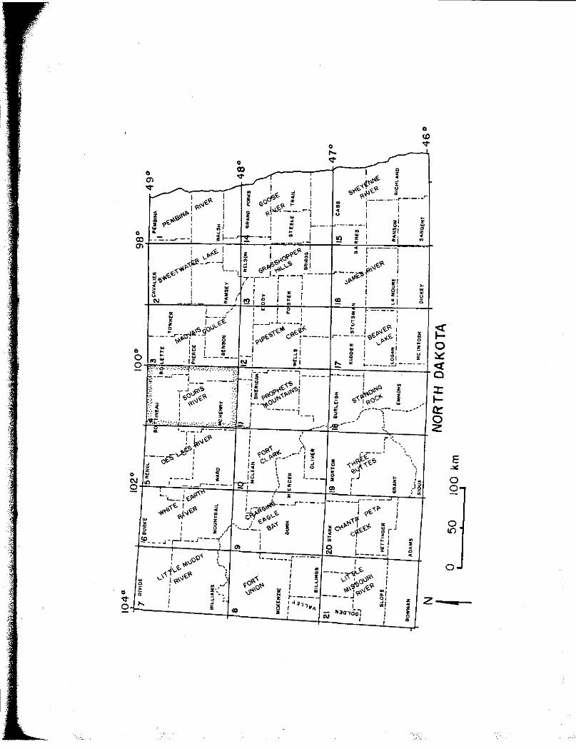
Figure 7. Location of Souris River Map Area (outline stippled) and other North Dakota Geological Survey Atlas Series map areas.
. i i I ,:,oO I . "' "' 1"" \ \"' ,J~~ . \,. r~\ 0 J ;; I -.:, • "
I.
,:- I ' 0 .... ' ..
,,
•
I ! ... -·-~~ av~' I
I ,.,ef'.> ,, .. ~ :d ·~, -----~ o, I "' i iv Nao,Oal
I i
' !! ~I .. •1
I
i
• • • 0 •
z • • • 0 • .
• ID ,:-
> • • u
"
z
E ..,. 0 0
0 ll")
0

33
conjunction with the Garrison Diversion irrigation project.
Various contour maps were constructed, including elevation,
structure, isopach, and textural variation maps. Preliminary contour
maps were made using a computer program (LeFever, 1986b); these maps
were modified slightly to conform better to the geologic setting.
Trend-surface analysis was applied to several surfaces, also using a
computer program (LeFever, 1986c), to test for statistical
significance.
In addition to the above described analytical methods, the
depositional processes, fan development, and paleoflow conditions of
the coarse-grained sediments in the Lake Souris basin were considered
in conjunction with existing models.

LITHOFACIES AND STRATIGRAPHY
Description of Lithofacies
Introduction
The lithofacies descriptions that follow are based largely on
samples that were collected by from sample holes drilled for this
project. In the few places within the study area that exposed
sections of sediment do occur, the information from them is
incorporated into the descriptions. The samples collected from the
auger flights tended to be deformed during drilling; thus, there are
limitations on the types of information that can be obtained from
these samples. For example, descriptions of sedimentary structures
are limited to the presence or absence of laminations and their
thicknesses. In addition, little information about the character of
contacts between lithofacies can be derived from the data collected.
Five major lithofacies have been identified in the sediments
studied: diamicton, laminated silt and clay, matrix-rich gravel,
matrix-deficient gravel, and sand. Relative abundances of different
facies could be calculated; however, because sampling was biased
towards certain sediment types to meet the objectives of this study,
these values would have little meaning. Instead, the approximate
number of samples collected from each facies is given to help
34

;
35
establish the basis of the descriptions. Detailed sediment sample
descriptions are given in Appendix A.
Diamicton Lithofacies (D)
The diamicton lithofacies consists of unsorted, matrix-supported
gravelly sand, silt, and clay. About 65 percent of the 110 diamicton
samples (from 37 holes) are massive, whereas the remainder exhibit 1
to 3 cm thick indistinct layering (Fig. 8). The average textural
composition of the samples composing the diamicton facies is 3.7
percent gravel, 34.5 percent sand, 38.8 percent silt, and 23.0 percent
clay (Remple, 1987). Maximum clast size in the samples averages about
1.5 cm. The average lithology of the very coarse sand fraction of the
samples is 3.,1 percent shale, 68.4 percent crystalline, 23.0 percent
carbonate, 3.6 percent sandstone and siltstone, and 1.9 percent
lignite (Remple, 1987). The thickness of this facies is not known
because drilling was seldom continued to its lower contact.
Laminated Silt and Clay Lithofacies (SCl)
The laminated silt and clay lithofacies consists of thinly
laminated silt and clay; very fine sand laminations do occur within
this facies, but are scarce {Fig. 9). About 150 samples from 37 hole;
are included in the laminated silt and clay lithofacies. Laminations
are typically about 1 mm thick and range from 0.3 to 10 mm thick. The
majority of the laminations are rhythmically laminated, consisting of
alternating layers of silty, lighter sediment with clayey, darker
sediment. ln some places, the rhythmites are texturally homogeneous

l I " 11
i
...._
36
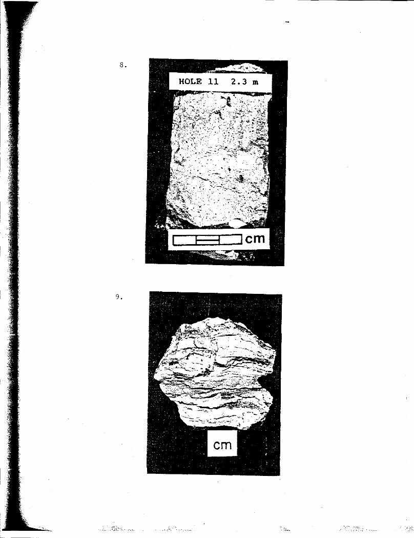
Figure 8. Sediment sample of diamicton lithofacies. Sample is from hole 11 at a depth of 2.3 m.
Figure 9. Sediment sample of laminated silt and clay lithofacies. Sample is from hole 5 at a depth of 14.6 m •
l
8.
9.

38
and laminations are discerned on the basis of lithologic differences.
Lighter laminations consist almost entirely of quartz whereas darker
laminations contain some dark particles, commonly lignite. Small
sections of apparently massive clay and silt do occur, but are rare.
The occurrence of outsize particles, such as very coarse sand,
within the sediment is not uncommon. The thickness of the laminated
silt and clay facies varies from less than 1 m up to about 5.5 m.
Matrix-rich Gravel Lithofacies (Gmr)
The matrix-rich gravel lithofacies is distinguished from the
matrix-deficient gravel lithofacies (next section) in that they
contain an abundance of fine-grained matrix material and commonly
contain lignite clasts (Fig. 10). Most sediments of both gravel
lithofacies contain more sand than gravel, but all of the sediments
are gravelly. The term gravel is used in the lithofacies names
because gravel is readily observed in the sediments of the two gravel
l ithofacies.
The sediments of the matrix-rich gravel lithofacies are poorly
sorted and generally contain particles as small as very fine sand and
silt; clasts up to 10 cm in diameter were obtained during augering.
About 50 samples from 13 holes are included in this facies. Lignite
clasts are common throughout sediments of this facies; they account
for about 90 percent of the gravel-size particles in some samples.
Lignite is also abundant in the matrix material. Clasts of other
highly erodable lithologies, such as laminated clay and diamicton,
occur within these sediments, but are rare.

-
39
Figure 10. Sediment sample of matrix-rich gravel lithofacies; note presence of lignite clasts (black particles). Sample is from hole 58 at a depth of 10.7 m. Note: the sediment is a grab sample off of the auger flight that has been dumped into a dish, thus, its appearance probably is not representative.
Figure 11. Exposure of matrix-deficient gravel lithofacies exhibiting indistinct tabular cross-bedding (dipping to northwest--left). Shovel handle is about 50 cm in length. Location of exposure is SE 1/4, sec. 35, T. 155 N., R. 77 W .
. , ,
$
f
11.
10.

41
The percentage of matrix material commonly decreases upward, as
does the amount of lignite. Thickness of this facies ranges from
about 0.5 m to 4 m. Sedimentary structures in this facies, if any,
were destroyed by augering or masked by the coarseness.
Matrix-deficient Gravel Facies (Gmd)
Sediments of the matrix-deficient gravel facies generally are
poorly sorted, although they tend to be better sorted than those of
the matrix-rich gravel facies. Most matrix material consists of
coarse and very coarse sand; lignite clasts are rare to absent. Well
sorted coarse and very coarse sands, with no lignite, are included in
this facies because they appear similar to the gravels and are
commonly gradational with them. Exposed sections of this facies occur
along terraces adjacent to the Souris spillway near its inlet to
Glacial Lake Souris. Fresh, undisturbed exposures of these sediments
are limited to a few square metres in area, but do show tabular cross
bedding with coset thicknesses of about 0.5 to 1 m (Fig. 11).
Particle diameters at the exposed sections are up to about 25 cm.
About 20 samples from 5 holes were collected by augering sediments
of the matrix-deficient gravel facies. Sections of this facies are up
to 3 m thick.
Sand Lithofacies (SJ
The sand facies comprises well-sorted to very well-sorted,
lignite-bearing sands (Fig. 12); coarse and very coarse silts with
similar characteristics are included in this facies, but are much less

42
Figure 12. Sediment sample of sand lithofacies with abundant outsize lignite clasts. Sample is from hole 9 at a depth of 4.5 m.
Figure 13. Exposure of sand lithofacies exhibiting climbing ripple cross-laminations; flow was to the north (left). Pocket knife is about 8 cm long. Location of exposure is SE 1/4, sec. 23, T. 157 N., R. 78 W.
1.3 ..
12 ..
..;.-$. -·~·.
-::_,
'4--... ' .. ~; .... ;, ",·-- ' -- :,;; .• ,::,;.,,._,,. ~ i'~z;. ,, ·~.i~ ;;, -~:-,·~)\~i~ ·, ;.·' .. ·~~ °' ~.· ·-"

44
common. Sediments from this facies are the most abundant, accounting
for over half of the samples collected (about 500 samples from 56
holes). The concentration of lignite typically varies between 2 and
10 percent. Exceptions occur in some near-surface sands, usually in
the upper metre, where lignite is rare or absent. Outsize lignite
clasts, up to 3 cm, commonly occur in otherwise well-sorted sands.
Sections of sand with outsize lignite clasts were present in 17 of the
holes sampled in the Lake Souris basin; these sections ranged from 1
to 7 m thick.
Most samples appear massive, but some exhibit indistinct layering
from 2 to 30 mm thick. The boundaries of the layers are marked by
higher concentrations of lignite. One exposure of the sand facies
does occur in.the southwestern portion of the Lake Souris plain (SE
1/4, sec. 23, T. 157 N., R. 78 W.); the sediment consists of fine and
very fine sand, and exhibits climbing ripple cross-laminations and
about 1 cm thick planar bedding (Fig. 13).
The thickness of the sand facies ranges from about 1 m to 25 m;
thick, homogeneous vertical sections are common. Sediments of this
facies are in some places gradational with those of the matrix-rich
gravel facies; the sand most commonly occurs above the gravel.
Description of Stratigraphy
Purpose
The purpose of this section is to describe the locations 1n which
the five 1 ithofacies occur within the Lake Souris basin, to
demonstrate the vertical and lateral relationships between facies, and

45
to show the geometry of some of the lithofacies surfaces. Following
the description of stratigraphy, the lithofacies are interpreted,
based on information presented in the descriptions of the lithofacies
and information presented in this section.
Occurrence
The most widespread lithofacies is sand which occurs throughout
the entire lake basin. The diamicton facies is also widespread and
was encountered in most places, except for a group of holes bored on
the north edge of the detailed study area (Fig. 14). Where this
lithofacies was sampled, it occurred almost exclusively beneath the
other lithofacies; it is likely, therefore, that the absence of
diamicton in some holes simply means that holes were not bored deeply
enough to reach it.
The remaining three lithofacies are less widespread (Fig. 15).
The laminated silt and clay lithofacies is not present in the vicinity
of the inlet to Lake Souris. Conversely, the two gravel facies are
present in the inlet area and immediately adjacent to the Souris
spillway. The distribution pattern for the silt and clays versus the
gravels are almost opposite (Fig. 15).
The surface distribution of the different lithofacies is shown on
the geologic map of Lake Souris (Fig. 4, Appendix D) (Lord, 1988). In
Figure 4, the diamicton lithofacies is equivalent to till (map units 6
to 13; Appendix 0), the laminated silt and clay facies to clay and
silt (map unit 16; Appendix D), the two grave1 facies to sand and
gravel (map unit 14; Appendix D), and the sand facies to sand (map

46
Figure 14. Location of holes where diamicton lithofacies is present. Dots indicate hole locations. The outline of the southern half of Lake Souris and the Souris spillway are marked for reference. The same outline will be used throughout the text.
Figure 15. Location of holes where laminated silt and clay (SCl), matrix-rich gravel (Gmr), and matrix-deficient gravel (Gmd) lithofacies are present.
14. ~ &. • • & • • • • •
£ • • •
&. &. &. ,t.
& DIAMICTON ~ &.
•
0 '5 10 km
15.
~SCI
!f.!Jj Gmr
@Gmd
1;;;,:,-..

48
units 3, 4, 5, and 17; Appendix D). The geologic maps reinforce prior
observations, namely, the abundance of sand throughout the study area
and the restriction of gravel to the inlet and spillway areas.
Braided channel scars are present on the gravel surface a few
kilometres northeast of Verendrye (Appendix D). In addition, the maps
do demonstrate that at the surface silt and clay become more extensive
in the northern part of Lake Souris, beyond the area of detailed
study.
Vertical and Lateral Lithofacies Relations
Typically, the sequences of lithofacies within Lake Souris are
simple; most lithofacies occur in only one position in the holes
bored--they generally are not repeated. A structure contour map of
the diamicton lithofacies, which underlies the other lithofacies,
shows two shallow depressions in the study area, one in the southern
portion of the study area and a second to the north (Fig. 16). The
two topographic lows are separated by a linear high that trends
northwest-southeast with about 20 m of relief (subsurface).
The laminated silt and clay, sand, and gravel lithofacies all
commonly overlie the diamicton lithofacies. The frequency of vertical
transitions between lithofacies is shown in Table 2. Sand, the
uppermost lithofacies in 52 holes, most commonly overlies the two
gravel facies and the laminated silt and clay. Representative
geologic cross-sections, parallel and perpendicular to the Souris
spillway across Lake Souris, exhibit the major vertical and lateral
sequences of the different lithofacies in the lake basin (Figs. 17 and
49
Figure 16. Structure contour map of the diamicton lithofacies. Sea level is datum.

• • <'· . 0 10km C.l= 5 m

51
Table 2. Frequency of vertical transitions between lithofacies. Only holes located within detailed studied area are included. Lithofacies key: D=diamicton, SCl=larninated silt and clay, S=sand, Gmr=matrix-rich gravel, Gmd=matrixdeficient gravel.
OVERLYING
FACIES D SCl s Gmr&Gmd TOTAL
D --- 12 10 8 30
SCl 0 --- 21 3 24
s 1 1 --- 4 5
Gmr & Gmd 1 0 12 --- 13
TOTAL 2 13 43 15 73

I
I~
52
Figure 17. Geologic cross section of the Lake Souris basin sediments oriented parallel to the Souris River.

A H-52 467m H-31 H-32
439m 460m H-1 .. :,;
LITHOFACIES
!-:":<.:I SAND
\;. /
f9] MATRIX -RICH GRAVEL
I~~ MATRIX-DEFICIENT GRAVEL
~ LAMINATED SILT a CLAY
K"!'i1 DIAMICTON
455m
f,. \'
' "1. ,>9, ,., ·d'-.'
rT71 INDISTINCT IL.d BEDDING 1.-.:jouTSIZE LIGNITE
I -=l SILTY
1·~•0
.~ SANDY
?
N
~
H-42 447m
. ·. ·.·. .· .. ·
5
m
A'
H-49 448m
v.· (.) /: .• ,1
VE-1800X
o-+--~~ 0 5 10
km

' ~, •, -
54
Figure 18. Geologic cross section of the lake Souris basin sediments oriented perpendicular to the Souris River.
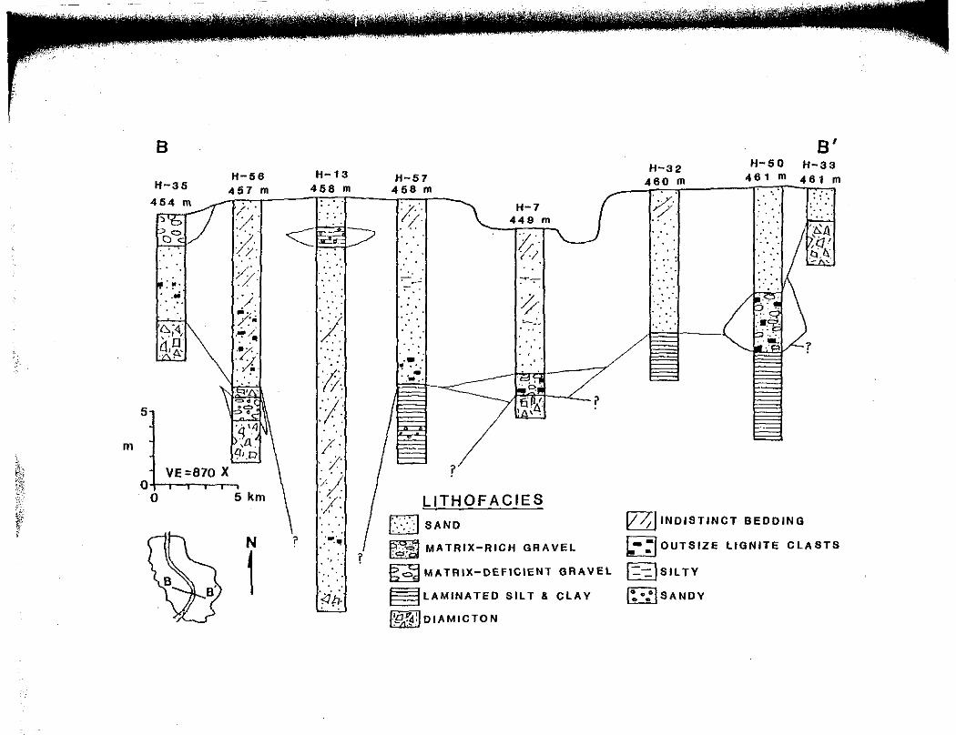
5
m
ti! 0
r ;
B
H-35
.. "" .. ...
H-56 457 m
/• . :/·
>r :,,;: ·j_ '";:: /.'•
·~~ '7· . ;{ . ' .
VE ::870 X
O 5 km
N
1
H-13 456 m
/ ... .. ..
/). :;. .. /· ·/ ~'/. ...
·/' .. . '
? I:·:~ I .
r :I ...
i:Jt,.
H-57 456 m
1: ...
C"
?
H-7 449 m
/; i>" ~7"
1 ~-
LITHOFACIES
I\·>>! sAND
Fff"fil MATRIX-RICH GRAVEL
?
~ MATRIX-DEFICIENT GRAVEL
§LAMINATED SILT & CLAY
l'.9<,!'ii:I DI AM IC TON
H-32 460 m
;;·
B' H-50 H-33
461 m 461 m
~ INDISTINCT BEDDING
L-:1 OUTSIZE LIGNITE CLASTS
l=-::!SIL TY
ro:.,SANDY ~

56
18). Common lithofacies sequences, also implied by the frequency
transition matrix, can be seen in the cross-sections, for example,
diamicton to gravel to sand (holes 7, 11, 31, and 52), diamicton to
silt and clay to sand (hole 49), and laminated silt and clay to sand
(holes 32 and 57) (Figs. 17 and 18).
The influence on sedimentation of the two shallow basins on the
diamicton facies surface is demonstrated in Figure 17; the overlying
facies are thicker in the basins. In addition, the presence of gravel
is shown near the inlet and again downstream from the topographic high
on the diamicton surface. Laminated silt and clay are present at the
surface in hole 1; this is coincident with the northwest-southeast
band of silt and clay shown on the geologic map of Lake Souris (Fig.
4).
Interpretation
Introduction
The presence of an irregular contact between the diamicton and
the laminated silt and clay, the variable thickness of the silt and
clay, and the almost exclusive occurrence of gravel or sand capping
the sequence indicates a diverse sedimentation history. A complex
glacial origin for Lake Souris was followed by quiet-water
sedimentation of silt and clay that was abruptly halted by high-energy
deposition of sand and some gravel.
Interpretations presented in this section are brief and, for some
lithofacies, preliminary. More detailed characteristics and
interpretations of outburst-related sediments will be presented later
in the text.

57
Diamicton Lithofacies (D)
Most sediments comprising this lithofacies are interpreted to
have been directly deposited by glaciers; this is consistent with the
lithology, pattern of occurrence, and glacial history of the area.
Also, the patterns of sedimentation are consistent with prior
interpretations of deposition of till from stagnant ice (Moran and
Deal, 1970; Clayton, 1980; Bluemle, 1982). Some of the layered,
gravelly diamictons may represent mudflow deposits off the ice, and
thus, technically are not tills (Lawson, 1982).
The origin of the linear topographic high separating the two
shallow basins on the diamicton surface is uncertain, but it may
represent a minor ice-margin position (Remple, 1987). A possible ice
margin in this_ area also is suggested by the presence of ice-thrust
depression-hi 11 forms that indicate local glacier movement from the
northeast (Bluemle, 1988). The linear high on the diamicton surface
will subsequently be referred to informally as the till high.
Laminated Silt and Clay Lithofacies ($Cl)
The laminated silts and clays are interpreted to be low-energy
glacial-lake deposits. It is unlikely the rhythmites are varves
representing annual layers of sediment accumulation, because thinness
of the rhythmites (about l mm) coupled with the thickness of the
laminated silt and clay sections {up to 5.5 m) would imply thousands
of years of sediment accumulation. This length is well out of the
realm of the presumed life of the lake of just several hundred years
(Clayton and Moran, 1982). Alternatively, the origin of the majority

58
of the laminations may be due to diurnal fluctuations in meltwater
input, intraseasonal meltwater fluctuations, or slump-generated
turbidites (Smith, 1978; Smith and Ashley, 1985; Liverman, 1987).
The absence of thick laminations, the lack of coarse-grained
sediment, and variable thickness in the laminated silt and clay
lithafacies suggests a low-energy environment. This is consistent
with earlier interpretations suggesting that Lake Souris originated as
isolated supraglacial lakes an stagnant ice (Moran and Deal, 1970;
Deal, 1971); glacier-meltwater input would have been small and
sediment-accumulation thicknesses would have been variable.
Matrix-rich Gravel Lithofacies (Gmr)
Poorly sorted, lignite-bearing, matrix-rich gravels are
interpreted ta have been deposited rapidly from inertia-driven and
gravity-driven density flows into Lake Souris. This interpretation is
supported by several kinds of evidence. (1) This facies, Gmr, is
present at large depths (aver 10 mat holes 30 and 58, Figure 6)
within the basin, at long distances from any inlet into Lake Souris.
Density currents can transport sediment tens of kilometres from an
inlet source (Houbolt and Jonker, 1968). (2) Lithofacies Gmr is not
present at the surface. Sediments deposited by underflows, such as
flow from a density current, are restricted to topographically low
areas and do not occur on highs (Smith and Ashley, 1985). (3) These
poorly sorted sediments contain fragile clasts whose sources were at
least tens of kilometres away; transport by normal bedload processes,
as in a braided river, probably would have destroyed such clasts.

59
Transport by a fluid of relatively high viscosity, where turbulence is
dampened and larger clasts are more likely to be transported in
suspension, is consistent with this facies interpretation (Hein, 1982;
Eyles, 1987; Lord and Kehew, 1987). (4) Almost all sediments of this
facies grade upward into sand (the single exception, hole 31, grades
to matrix-deficient gravel); sediments typical of a prograding delta
coarsen upward (Leckie and McCann, 1980).
Matrix-deficient Gravel Lithofacies (Gmd)
The matrix-deficient gravels are interpreted to have been
deposited by braided rivers. Evidence for this includes the
occurrence of facies Gmd near and at the surface in the vicinity of
the Souris spnlway, the poor sorting, the tabular cross-bedding in
exposures, and the channel scars on the surface of the sediment.
Sediments of this facies tend to be better sorted than those of the
matrix-rich gravel facies, and contain much fewer fragile clasts, such
as lignite. These characteristics, in addition to those just
described, conform to gravel deposits of braided rivers as opposed to
deposits of high-density flows (Hein, 1984).
Sand Lithofacies (S)
Dunes are developed in a large portion of the sand lithofacies
surface; therefore, much of the near-surface sediment of the sand
facies has an eolian origin, Moreover, the thick sections of well
sorted sand in the subsurface must represent a depositional
environment in which the deposits can be easily reworked to form
~·-~·----------------
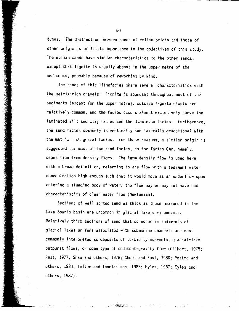
60
dunes. The distinction between sands of eolian origin and those of
other origin is of little importance to the objectives of this study.
The eolian sands have similar characteristics to the other sands,
except that lignite is usually absent in the upper metre of the
sediments, probably because of reworking by wind.
The sands of this lithofacies share several characteristics with
the matrix-rich gravels: lignite is abundant throughout most of the
sediments (except for the upper metre), outsize lignite clasts are
relatively common, and the facies occurs almost exclusively above the
laminated silt and clay facies and the diamicton facies. Furthermore,
the sand facies commonly is vertically and laterally gradational with
the matrix-rich gravel facies. For these reasons, a similar origin is
suggested for most of the sand facies, as for facies Gmr, namely,
deposition from density flows. The term density flow is used here
with a broad definition, referring to any flow with a sediment-water
concentration high enough such that it would move as an underflow upon
entering a standing body of water; the flow may or may not have had
characteristics of clear-water flow (Newtonian).
Sections of well-sorted sand as thick as those measured in the
Lake Souris basin are uncommon in glacial-lake environments.
Relatively thick sections of sand that do occur in sediments of
glacial lakes or fans associated with submarine channels are most
commonly interpreted as deposits of turbidity currents, glacial-lake
outburst flows, or some type of sediment-gravity flow (Gilbert, 1975;
Rust, 1977; Shaw and others, 1978; Cheel and Rust, 1980; Postma and
others, 1983; Teller and Thorleifson, 1983; Eyles, 1987; Eyles and
others, 1987).

61
Development of Lithofacies Sequences
Determining the order in which the lithofacies were deposited is
straightforward because the vertical sequences are uncomplicated.
Deposition of the diamicton facies occurred first, followed by the
laminated silt and clay facies, followed by the sand and gravel
facies. Where the sand and gravel facies occurs in the same vertical
section, the sand overlies the gravel in almost all places.
The inundation of Lake Souris by outburst flows from Lake Regina
caused the complete drainage of Lake Souris (Kehew and Clayton, 1983);
hence, the outburst-deposited materials should be the uppermost
sediments (sands and gravels) in the lake basin. Of interest to this
study is the identification of sediments deposited by the outburst
flows. First,. is the deposition of the silt and clay due to the same
event (process) as that responsible for the sand and gravel facies?
Second, is all of the sand and gravel related to the outburst or is it
polygenetic?
The laminated silt and clay sediments generally are not
considered to be related to the outburst flows. They occur throughout
the lake basin and do not appear to be gradational, vertically or
laterally, with the overlying sand and gravel sediments. Furthermore,
if the laminated silts and clays are related to inflows from the
Souris inlet, the laminations should thicken an.d coarsen toward the
inlet (Ashley, 1975; Gustavson and others, 1975); they do not. Their
origin is most consistent with a quiet-water lake environment,
possibly multibasinal in its early stages (Moran and Deal, 1970; Deal,
1971), and not related to deposition from outburst flows. Possible
62
exceptions may occur in portions of the lake basin distal to the
Sour\s inlet.
The sand and gravel lithofacies are vertically and laterally
continuous throughout the lake basin, with the exception of the
northwest-southeast trending deposit of silts and clays (Fig. 4)
directly overlying the till high (Figs. 16 and 17). These coarse
sediments represent a sudden change in the energy of the lake and are
interpreted as deposits from the outburst flows from Lake Regina. It
is reasonable to ask, however, whether the occurrence of sand and
gravel on either side of the till high is related to the same event or
to two periods of deposition at different levels of Lake Souris. The
primary evidence for two periods of deposition is the presence of two
separate gravel deposits: a fan-shape one at the Souris inlet and a
more elongate one near Towner, just upstream of the northwest
southeast trending deposit from silt and clay (Fig. 4).
Evidence for only one event includes the homogeneity and
continuity of the sand and gravel sediments; there is no disruption in
the sediment sequences. For example, if the northern fan was formed
in an earlier, smaller Lake Souris, then fine-grained sediments from
the later, larger Lake Souris should be e~pected to overlie the sand
and gravel (Liverman, 1987). Furthermore, the morphology of the
Souris Valley does not suggest two periods of deposition. If the
topographically higher southern fan formed first, the fan sediments
should be expected to exhibit regular incision from th·e Souris inlet
to the northern fan. Although the eastern side of the Souris River
valley is bounded by a relatively well-defined scarp, the western side

63
is not. To the contrary, former channel scarps demostrate that
substantial flow was at times directed away from the Souris River to
the north and north-northwest" (Fig. 5; Appendix DJ. Moreover, all of
the overflow channels west of Lake Souris terminate at the mapped
limit of the lake (Fig. 5; Appendix DJ. If Lake Souris was smaller
and confined to the northern portion of the basin at the time of the
outburst, the overflow channels should extend well into the lake
basin.
In addition to the sedimentary and morphologic evidence against
two periods of fan deposition, the occurrence of two fans can
adequately be explained by one period. It can reasonably be assumed
that the water volume of Lake Souris increased significantly upon
arrival of the outburst flows and that lake currents increased
markedly, especially once drainage of Lake Souris began. The till
high may have acted as a barrier to lake currents causing water to be
funneled through the gap at the present location of the Souris River.
Flow competence through the constriction probably would have been
higher, thereby accounting for the coarse-grained sediment fan at that
location.
To summarize, Lake Souris originated as a low-energy glacial lake
that had little meltwater input, as indicated by the scarcity of
coarse-grained material. Fine-grained sedimentation was curtailed by
the arrival of flows from the outburst of Lake Regina. The outburst
flows deposited vast amounts of coarse-grained sediment, especially
sand. In the sections that follow, the sediments deposited by the
outburst flows will be described and interpreted in more detail. In
-· i.::. ·'

64
addition, the interrelationships of the different types of deposits
and the development of the coarse-grained fan will be considered.
SEDIMENTOLOGY AND DEVELOPMENT OF OUTBURST SEDIMENTS
Introduction
Descriptions are given in this section of, first, the textural
characteristics of the sediments deposited by the Lake Regina outburst
and, second, the pre-outburst and post-outburst setting of Lake
Souris. Following the descriptions, the flow conditions and
depositional processes active in the development of the coarse-grained
fan will be interpreted. The term "fan" is a non-genetic term used to
describe to the outburst-deposited coarse-grained sediments in Lake
Souris. Also, the accumulations of the coarse-grained sediment on
either side of the till high will be referred to as the southern fan
and the northern fan.
Textural Description
The outburst-deposited sediments are well represented among those
analyzed for texture, except for gravel (lithofacies Gmd) that occurs
at the surface near the Souris inlet. In the inlet area, because
drilling was expected to be difficult and because numerous exposures
already exist there, few gravels were analyzed. Given that the
textural data are not fully representative of all the coarse-grained
outburst sediment, the textural characteristics are described below.
65
66
About 50 holes drilled for this study are within the detailed study
region; textural analyses were conducted for samples from 38 of these
holes.
The bulk characteristics of the sediment are represented in
Figure 19 a to d. The outburst sediments are composed mostly of fine
to medium sand (Fig. 19a) and generally are well sorted to moderately
well sorted (Fig. 19c). The coarsest one percent of most samples
ranges from fine sand to coarse sand (Oto 3 phi), but is gravel in
numerous samples. The modal tendency of skewness is not as narrow as
the other textural parameters; the average value is 0.03, which is
essentially symmetrical. The values of textural parameters for
individual samples are listed in Appendix B; individual percentages
for quarter-phi intervals of all samples are listed in Appendix C.
Plots of sorting versus mean and of coarsest one percent versus
median (Fig. 20 a and b) both show two groups of samples; the largest
group contains sediment as coarse as about 1 phi (medium sand).
Sediments comprised of medium and finer sands are very well sorted to
moderately well sorted (sorting between 0.3 and 0.9) (Fig. 20a).
Conversely, sediments coarser than medium sand show a general trend of
becoming more poorly sorted with increasing grain size.
Grain-size distributions of samples analyzed for texture vary
considerably between different lithofacies. The sands most commonly
are well sorted with unimodal size distributions (Fig. 21a).
Typically, both gravel facies are poorly sorted, but the matrix-rich
gravels generally exhibit polymodal distributions with no strong modal
group (Fig. 21b), whereas the matrix-deficient gravels are more
.-::.:...~.;.-,_"·
b
67
Figure 19-. Histograms of 5 tex tura 1 parameters for a 11 samp 1 es (n=169); a) mean and median, b) coarsest one percent, c) sorting, d) skewness.

.. °:·' ~i.
;I,
{}'.
60
50 >-~ 40 w ::> 30 0 w a: 20 IL.
10
a. MEAN ANO MEDIAN
0 r<,q."'" 1up:::,r VC~>J ccqYt vt:p:t "4"'' -1-0 0-1 1-2 2-3 3-4 4-5
PHI INTERVAL ~MEAN ~MEDIAN
C. SORTING 80 -i-~---~~~~~~~~
70
>- 60 l) Z 50 w ::> 40 0 W 30 a: IL. 20
10
o 1,0,a ~ Wpl ~ ~ I I (.35 .35-.5 .5-.71 .71-1 1-2 2-4
PH I INTERVAL
b. COARSEST ONE PERCENT 60 -,-~~~~~~~~~~~~--,
50 )-
(.) 40 z w :::> 30 0 w a: 20 IL.
10
Q V~O I (( I V/d YyZ! FZ71 C/(d 1/{4 Vt;,O V{/1
<-4 -4~3 -3~2-2~, -1-0 0-1 1-2 2-3 3-4 PHI INTERVAL
d. SKEWNESS
40 I W,?l I 35
>- 30 (.) z 25 w :> 20
~ 15 a::: IL. 10
5
0 r1µ1 ~ t¥1 Fq;I ~ l*1 ~ (-1 -f·-.3-.3·-.l-.f-.l .1-.3.3·1 )I
PH I INTERVAL

69
Figure 20. Cross-plots of a) sorting versus mean, and b) coarsest one percent versus median; n=169. Lines on plots are zero lines for reference.

a.
'&
0 z ;:: "' 0
"'
b.
'&
!II -... "' "" "' "' < 0 0
2.6
2.4 -
2.2 -
2-
t.8 -
1.6 -
1.4 -
1.2 ·
1 -
o.s -
0.6 •
0.4 ·
0.2 -
0 -1
5
4
3
2
I
0
-I
-2
-3
-4
-5 -5
a
Do
a D
0
C
0
0
0
-3
0
0
a
a
a
' ' ' 1 3 5
i.tEAN </)
0
D
cP
cP a
0
0 0
C
a 0
-1 1 3 5
i.tEDIAN r/)

...
71
Figure 21. individual and cumulative frequency grain size curves for representative samples of a) sand lithofacies, b) matrix-rich gravel lithofacies, and c) matrix-deficient lithofacies .

-- --------------
a. HOLE 12 12.5 m
~ 30 99.99 Cl 99 LLl ~
e:20 0
90 0 ...J LLl
50 <t a: :::, LI.. 0 10 :i 10 > :::, 0 (.) I z
0 0.01 203 4 2 03 4
b. HOLE 30 42.5 m
~30 0
99.99 c:,
~ 99 w 0
E 20 c:, 90 ...J LLl
a: 50 <t LI.. :::, 10 Cl :::;; 10
> :::,
Cl (.) I
z 0 0.01 -3 -2 -I 001 3 4 -3 -2 -I 0 I 2 3 4
0
C. HOLE 5 2.5m
,,e 30 0 99.99 Cl ,,e 99 w 0:
0
LI.. 20 0 90 ...J ~ 50 <t
- :::, LI.. 0 10 :::;; 10 > :::,
I 0 u z
0 0.01 -4 -3 -2 - I 0
0 2 3 -4 -3 -2 -1 0
0 2 3
... , ..

73
commonly bimodal (Fig. 21c).
Vertical textural variations of sediments were examined by
plotting textural parameters versus depth. As with grain-size
distributions, there are considerable variations in trends throughout
the Lake Souris basin. About half of the holes exhibit little
textural variation with depth; that is, the mean grain size varies
less than about 1.5 phi over the depth of the hole. In most cases,
these holes show a gradual coarsening upward. Sediments from some
holes, such as 13, are remarkably homogeneous over their entire depth
(Fig. 22a). About 20 percent of the holes show a coarse sediment
spike at the bottom of the outburst sediment and then fine upward into
homogeneous sections (Fig. 22b). Two holes, one near the Souris
spillway and the other near the western edge of Lake Souris, have
coarsening upward trends (Fig. 23a). The remaining holes have
irregular trends with more complex patterns (Fig. 23b).
Hole depth versus mean sediment size data may be used to
construct cross sections to show lateral variations. Vertical trends
within holes show little correspondence to other holes, although the
amount of textural variation between holes is generally small--most
are sand (Fig. 24).
Contour maps of sediment textural parameter values were
constructed to show areal variations over the Lake Souris basin,
Textural data presented in this manner permit large-scale trends to be
observed and include all the data. Textural parameters (mean,
coarsest one percent, sorting, and skewness) were averaged for each
hole and then contoured. Because the majority of holes exhibit little

- -- --------------------
74
Figure 22. · Selected plots of depth versus textural parameter values for a) a homogeneous section, b) a section with a coarse-grained spike at the bottom of the outburst sediments.

a. HOLE 13 COARSEST lY. Al!D MEAN SOR!!NG smmrss
-4 -3 -2 -1 0123,4,S 0 l 2 -2 -1 0 l 2 0 ·:·" '"" 0 ' " . '' 0 •"'.'"
D 3 r 3 3 p ! { : ~ 1 r 6 H 6
l ' ii ) N
: j \ :
9
M I ,.
i 12J 12 12 I ,
\ E IS 15 15 s
18 18 18
21 21 21
2~ 24 24
27' .. l1 . 2'I
b. HOLE 58 COARSEST lY. Al!D MEAN SORTING smmrss
-4 -3 -2 -1 0 l 2 3 4 S 0 l 2 -2 -I ~, I 2 , ' l I IP• I'• I, I, I 0 J II : 0 '
D { \ . E 3 3 /: 3 p r H 6 ·0 6 6 . .
I . . N 9 /- 9 9 . . M
. . . . E 12 12 12 r R r 15 15 15 s
18 18 18

76
Figure 23. Selected plots of depth versus textural parameter values for a) a coarsening upward section, and b) an irregular section.
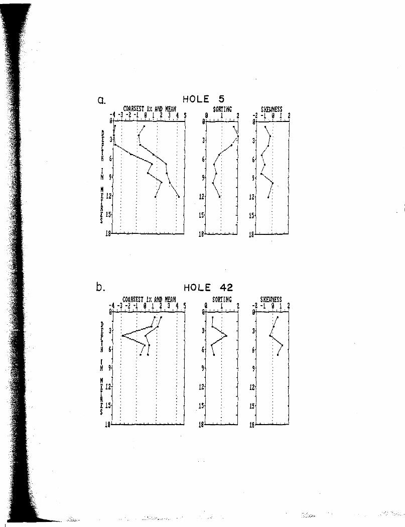
I -
a. COARSEST lX AND lfrilN
HOLE 5 SORT IN<:
·4 ·3 ·2 ·l 0 l 2 3 4 S i , .' I I l • I I o , I I o ! I 1 0 1 2
D I r 3i , . p •,, -~
: : ''-i \ 7 \\ M
E 12 r R E 15 s
0' ' I ' : I
\
'
lS
1s,~~-
b. HOLE 42 COARSEST IX AND HEAN SORTING
·4 ·3 ·2 ·! 9 1 2 3 4 S 0 1 2 0 I ' I J I t t I I , , I I t ' I I' I I
' ' ' .
<t' ~ D ' ' ' ' ' .
E 3 : : r".' 3 p . ' '
' ' ' ( r ' ' ' ' '
H 6 ' ' ' 6 ' ' ' ' • It •
I H 9 9
M E 12 12 l R
.
E JS 1S s
'
18 ' ' ' 18 ·
smmrss ·2 • l 0 1 2 0 ' ' '
\ 3 1
( 6 ';
1: ~/
15
SKDlNESS ·2 ·l 0 1 0' ' ' ' '
t 3
6
9
12
15
18 .
2

78
Figure 24. Cross section, oriented parallel to the Souris River, showing mean grain size of outburst-deposited sediments.
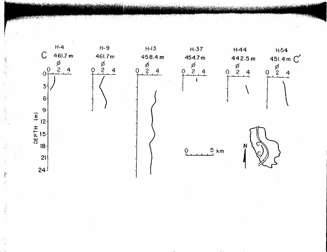
H-4 H-9 H-13 H-37 H-44 H-54 C ' 461.7 m 461.7m 458.4 m 454.7m 442.5 m 451.4m C ¢ ¢ ¢ ¢ ¢ ¢ 0 2 4 0 2 4 j 0 2 4 0 2 4 0 2 4 0 u r 31) ~ \ j \ 6i -l \ ~ \ J
' • ' ,
' 9 -E -12 I
:;: 15 w 0
18-1 ~ \ N 0 5 km
~ 2H ~ J
24' I I
~i r
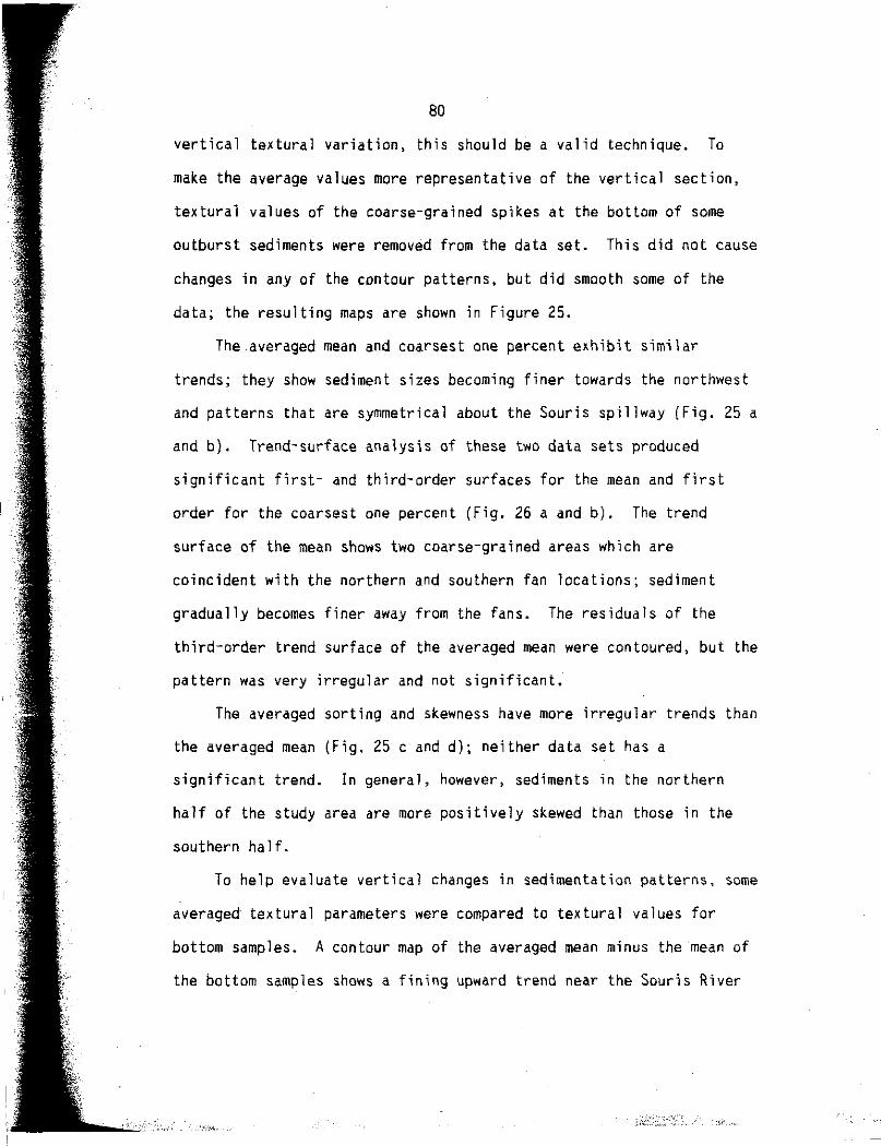
80
vertical textural variation, this should be a valid technique. To
make the average values more representative of the vertical section,
textural values of the coarse-grained spikes at the bottom of some
outburst sediments were removed from the data set. This did not cause
changes in any of the contour patterns, but did smooth some of the
data; the resulting maps are shown in Figure 25.
The.averaged mean and coarsest one percent exhibit similar
trends; they show sediment sizes becoming finer towards the northwest
and patterns that are symmetrical about the Souris spillway (Fig. 25 a
and b). Trend-surface analysis of these two data sets produced
significant first- and third-order surfaces for the mean and first
order for the coarsest one percent (Fig. 26 a and b). The trend
surface of the mean shows two coarse-grained areas which are
coincident with the northern and southern fan locations; sediment
gradually becomes finer away from the fans. The residuals of the
third-order trend surface of the averaged mean were contoured, but the
pattern was very irregular and not significant.
The averaged sorting and skewness have more irregular trends than
the averaged mean (Fig. 25 c and d); neither data set has a
significant trend. In general, however, sediments in the northern
half of the study area are more positively skewed than those in the
southern half.
To help evaluate vertical changes in sedimentation patterns, some
averaged textural parameters were compared to textural values for
bottom samples. A contour map of the averaged mean minus the mean of
the bottom samples shows a fining upward trend near the Souris River
'V·. ,,

,,----
I~
81
Figure 25 •. Contour maps of te~tura1 parameter va1ues averaged for each hole. Values of the coarse-grained spikes at the bottom of holes are not included in the averaged values; a) averaged mean, b) averaged coarsest one percent, c) averaged sorting, and d) averaged skewness,
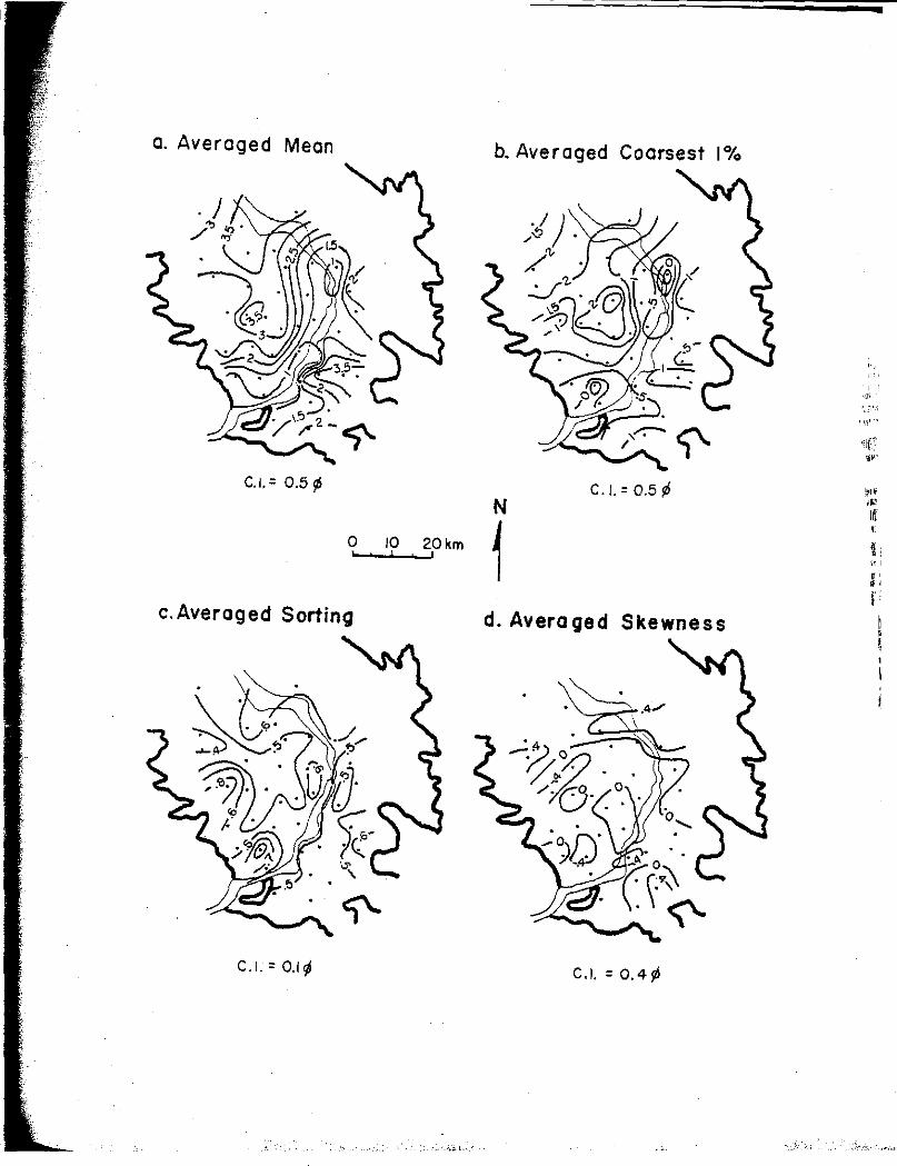
a. Averaged Mean
C.1.= 0.5 ¢
0 JO 20km
c. Averaged Sorting
C.I. = 0.1~
b. Averaged Coarsest 1°/o
C.l.=0.5¢ N
1 d. Averaged Skewness
C.I. = 0.4jll
\\\'.
itl
'' "' f: I I
' ~
I...._
83
Figure 26 .. Trend surfaces significant to the 97.5 percent level. a) Third-order surface of averaged mean grain size; explained variation= 67 percent (see Fig. 25a). b) First-order surface of averaged coarsest one percent; explained variation= 23 percent { see Fig. 25b) .

I
I
a.
N
~? ._ -'5'--.11 p km
C.l.=0.5 0
b.
N
~ 0 5 I 10 km -.....r.-.11
C.I.= 0.5 0
•
'!,~ •
•
/. •
• •
• ,'.:> •
• • • 'I:)
• •
• • •
•
<'
....

85
and coarsening upward trend elsewhere (Fig. 27a); averaged sorting
minus sorting of the bottom samples has a similar trend (Fig. 27b).
Pre-outburst and Po.st-outburst Setting of Lake Souris
In order to establish a complete framework for understanding the
effects of the outburst on Lake Souris, the conditions of Lake Souris
before and after the outburst should be examined. Important to
understanding the depositional processes of the outburst are 1) the
slope and depth of water in the Souris spillway just upstream from the
inlet to the Lake Souris basin, and 2) the water level of Lake Souris
at the time of the outburst. Unfortunately, there is little direct
information on either. The slope of the Souris spillway is taken to
be the slope of an erosional terrace that flanks the inner channel,
0.0019 (Christiansen, 1956; Lord and Kehew, 1987). Maximum water
depth estimates within the Souris spillway range from about 20 to 70
m, but about 45 mis considered most realistic (Lord and Kehew, 1987;
Komar, in press, a).
The elevation of the water in the Souris spillway at the time it
discharged into lake Souris is unclear, but a probable range of levels
may be estimated. Estimated water levels of Glacial Lakes Regina,
Souris, Hind, and Agassiz are plotted, in addition to high-water-mark
data from the Souris spillway (Fig. 28). These data indicate the
water level in the Souris spillway just upstream from lake Souris was
between 466 and 470 m. The elevation of Lake Souris at the time of
the outburst has been estimated to be about 448 m by Bluemle (1985)
and about 457 m by Kehew and Clayton (1983). Therefore, a head

IF I
x~·.;::..:.,.-K.- ,_, . ·
86
Figure 27. Contour map of textural parameter values. a) Averaged mean grain size minus mean gi·ain size of bottom outburst sample; positive values indicate fining upward. b) Averaged sorting minus sorting of bottom outburst sample; positive values indicate sediments become more poorly sorted upward.

a.
N
1 o 5 10 km
C. I. = 0.5 /6
b.
•
•
•
~· • 0
N
1 o 5 10 km
C.I. = 0.2 ¢
/· • •
s •
•

, 88
Figure 28. Regional topographic profile showing glacial lakes, spillway valley bottoms, and high-water marks of the Lake Regina outburst flows; ranges of possible lake levels also are shown.

(
600
550
500
-E ~
:z ~ 450 I-<t > w ...J w
400
350
300
LAKE REGINA
' ' ' ' ' ' '
++
' ',
u
' ' + ', X
'-, .x LAKE ', ~ SOURIS LAKE
u 'issssssssit r~~~ .. u ',
'-l, ',
~ INDICATES POSSIBLE RANGE IN WATER LEVELS
HIGH-WATER MARKS IN SOURIS SPILLWAY u + X HIGH -WATER MARKS IN SCA BLAND AREA EAST OF MINOT (KEHEW, 1982)
u SPILLWAY VALLEY BOTTOMS
e AREAS NOT ERODED BY OUTBURST
DATA COMPILED FROM: ELSON, 1955; KEHEW 8 CLAYTON, 1983; BLUEMLE, 1985; LORD, 1988
' ' '
0 100 200 300 400 500 600 700
DISTANCE FROM LAKE REGINA ( km)
' ' ' ' ··-··--u '...i \ \ \ \ (
800 900

90
difference of 9 to 22 mis implied between the water level in the lake
and the spillway.
Probable water depths throughout Lake Souris have been estimated
by assuming a lake level of 457 m and subtracting the elevations at
the base of the outburst sediments (Fig. 29). No corrections for
differential isostatic uplift have been made because it is not known
what, if any, they should be. Lake Souris was shallowest over the
region of the till high, and deepest in the northern basin.
The lake-basin configuration is reflected by the outburst
sediment patterns. Outburst-deposited sediment is thickest in the
southern basin and thinnest over the till high (Fig. 30). A detailed
cross section of the southern fan, which incorporates data from the
U.S. Bureau of Reclamation, shows an irregular pre-outburst lake
bottom and complex sediment patterns (Fig, 31). In general, the
sediments are coarsest near the fan apex and finer at the center of
the southern basin.
The morphology of the Souris spillway is reflective of the
discharges that formed it; because of this, numerous spillway cross
sections were made between the inlet area and the Souris-Hind spillway
(Fig. 32). Upstream from the Lake Souris inlet, the Souris spillway
has a well-defined trench shape with a scarp relief of about 25 m.
The relief of the valley diminishes to a few metres near the center of
the lake basin and then increases to about 25 m again near the
international border (Fig. 32 and 33).

b I
91
Figure 29. Contour map of the probable water depths in Glacial Lake Souris prior to inundation by the outburst flows.
Figure 30. Isopach map of the outburst-deposited sediments in the Lake Souris basin.

29.
WATER LEVEL ELEV.-4,7m
0 10, .. 1 C.l.=5m
30.
N
0 IOKm ! METRES CONTOURS IN
• •
,,-. ~.
·,l
93
Figure 31. Detailed structural cross section of the southern fan parallel to the Souris River. Hole data is from this study and the U.S. Bureau of Reclamation (USBR) (from Kehew and Lord, 1987).
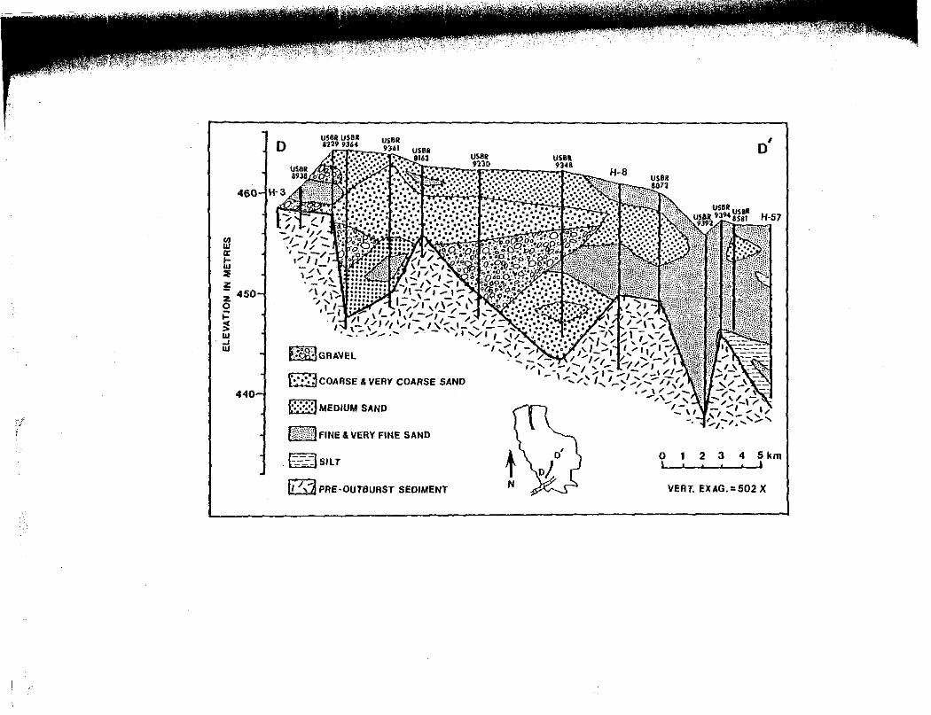
460
m er I-Ill lE l!: z 450 0 ;: ~ Ill _, Ill
440
,-_~
D US8R USBR 4229 9364
ff,$.,lGRAVEL
f•:;":~COARSE & VERY COARSE SAND
f:::::::j MEDIUM SANO
m FINE & VERY FINE SAND
[=::_::-__ ::=J SILT
11 /,i PRE-OUTBURST SEDIMENT
USBR 9'l'lD
US8l 9348
0
o'
-.
1 2 3 4 5 km
VERT. EXAG.=502 X
'1
95
Figure 32. Topographic profiles made perpendicular to the Souris spillway from the Lake Souris inlet area to the outlet area; probable water levels are also indicated •
.. ~

[f
·::._•
f:/ '
Elevation In Metres
WEST EAST
490j 480 470 460 450 490 480 470 46 450
470 460~···.:.::·~::.·:.:..·::. .. ··;,=
450 440
460 ----- ---------440
A
B
C
450r J
430 D
--------------450 4401-t-~~~~~ . ...,
430 E
::gr-------------440.t J 430 f
450 440...,...__
430
460 450
-~~------_/
440j---.. 430
460 450~ 440
430
460 450 440 430 460 450 440 430
G
H
I
CANADA --- --U.S.
LAKE
<;" N
0 10 20 km J I I ,
---- Lake Souris waler level ~457m
.............. High-water !eve!s In spillways

Ir· } ,J.' ~ •, i'
,.;,, ;,t
. I
97
Figure 33. Longitudinal topographic profile of the Souris spillway through Lake Souris; letters refer to profiles locations shown in Figure 32. Note that the topographic relief of the valley is greatest at the basin edges.

z
w Cl ::::> f-f....J <(
SOURIS VALLEY PROFILE IN LAKE SOURIS
G H
430
420~-.-~--,....--..---,--...----.----,~..---.-..,----.----,,--..--~ 0 20 40 60 80 100 120 140
DISTANCE FROM PROFILE 11A
11 IN KILOMETRES
o Valley Top 6 Valley Bottom -Lake Level
99
Discussion of Depositional Processes
Introduction
An analysis of the depositional processes active in the
development of the coarse-grained fan that formed in Lake Souris must
include the lithologic, sedimentologic, and stratigraphic evidence.
Furthermore, the depositional processes must be evaluated within a
framework established by the probable conditions of the Lake Regina
outburst, the geologic setting of Lake Souris, and processes known to
be active in analogous geologic settings.
Interpretations of lithofacies made earlier were purposefully
general. Detailed information presented subsequently on the textural
characteristics of the outburst-deposited sediments and on the
conditions in.Lake Souris before and after inundation by the outburst
permits further evaluation of depositional processes.
The Lake Souris fan is interpreted to have been formed by
deposition from braided rivers and various types of sediment gravity
flows. Distinguishing the sediments of different depositional
environments in Lake Souris is difficult, first, because of the
textural homogeneity of much of the sediment, and second, because of
the almost complete lack of sedimentary structures available to the
study. In this section, the characteristics and evidence for each of
the modes of deposition will be described.
Braided Rivers
As discussed previously, the gravel exposed at and near the
surface of the Lake Souris basin is interpreted to have been deposited
•:,,,·.

-~
100
by braided rivers because of 1) the presence of tabular cross-bedding,
2) the poor sorting of the sediment, and 3) the braided-channel scars
on the surface. The sediments deposited by braided rivers, those of
lithofacies Gmd, commonly have bimodal grain-size distributions; this
characteristic and the others listed above are typical of braided
river systems (Fahnestock, 1963; Williams and Rust, 1969; Miall,
1977). Other information also indicates that braided rivers should
have been present. The water-level in Lake Souris probably was not
higher than 457 mat the time of the outburst (Fig. 32, profile BJ,
but near the inlet, braided-channel scars underlain by gravel occur at
elevations up to about 468 m. The outburst flows probably went from
confined conditions within the Souris spillway to unconfined, but not
subaqueous, conditions within the Lake Souris basin (Fig. 34). In Lhe
unconfined reach, upslope from the 457 m lake level, braided river
deposits accumulated in a fan shape. Because of the large differences
in water levels between the spillway and lake, it is probable that
this intermediate area was entirely inundated with water during the
early stages of the outburst before braided rivers developed. In an
analogous setting, the Charlotte Lobe delta, Alaska, was inundated by
flows from the sudden release of water dammed within the Martin River
Glacier (Erickson, 1967).
Sediment Gravity Flows
Sediment gravity flows are important in the formation of deep sea
fans, marine deltas, and glacial-lake deltas (Gilbert, 1975; Rust,
1977; Hiscott and Middleton, 1979; Hein, 1982; Postma and others,
r ;
,-1
;.,
'I.
101
Figure 34. Selected elevations (in metres) on braided river gravel deposits at the Lake Souris inlet (modified from Lord, 1988) •
.• --1.-..:.1

+ + +
z st I{)
I-'
• / ~ ~
...... +
+ R. 78 W.
SELECTED ELEVATIONS
CHANNEL SCAR?
GRAVEL
GLACIAL SEDIMENT
(ml
N 0 ............................. ~;'
km 1 R. 77 W.
''h., ·,i.," •.
103
1983; Smith and Ashley, 1985; Eyles and others, 1987}. The importance
of such flows is also recognized in models of delta progradation
(Kenyon and Turcotte, 1985}. Because of the relevance of sediment
gravity flows to delta formation, and because the conditions in Lake
Souris were conducive to the formation of sediment gravity flows
(discussed below), a brief review of their characteristics is
presented.
Sediment gravity flows are driven by the force of gravity acting
on the particles in the flow (Lowe, 1979). Types of sediment gravity
flows include turbidity currents, liquefied flows, grain flows, and
debris flows (Middleton and Hampton, 1976; Lowe, 1979). The primary
mechanism of sediment support is different for each type of flow;
particles are supported by fluid turbulence in turbidity currents,
upward moving pore fluid in liquefied flows, dispersive pressure due
to particle collisions in grain flows, and a cohesive matrix in debris
flows (Lowe, 1982). Turbidity currents and grain flows are probably
of most importance to this study and will be emphasized. Turbidity
currents may be divided into low-density flows and high-density flows.
Low-density flows are typically comprised of clay- to medium sand-size
sediment that is supported entirely by turbulence. Such flows may be
generated by slumps or by continuous influx from·a river (Houbolt and
Jonker, 1968; Smith and Ashley, 1985). Deposition of the traction
load occurs first and then is followed by deposition of the suspended
load; deposits may conform to the Bouma's b through e divisions of
turbidity current deposits (Lowe, 1982).
High-density f1ows may be comprised of clay- to cobble-size

104
sediment; particle support mechanisms, in addition to turbulence, may
include buoyant lift, hindered settling, and dispersive pressure
(Bagnold, 1954; Lowe, 1982; Middleton and Southard, 1984). Dispersive
pressure is of little importance to particles smaller than granule
size except near the base of flows where particles are more
concentrated. Lowe (1982) describes three stages of sedimentation:
first, traction sedimentation; second, traction-carpet sedimentation;
and third, suspension sedimentation. Traction sedimentation forms a
layer of sand due to initial unsteadiness of flow. As flow continues,
particles become increasingly concentrated near the bed causing an
increase in grain to grain collisions with a concomitant rise in
dispersive pressure (a "traction carpet"). This traction carpet
continues to become more concentrated until frictional forces dominate
and the traction carpet "freezes" causing en masse deposition (Hiscott
and Middleton, 1979; Lowe, 1982). The third stage of sedimentation
occurs directly from suspension without going through a traction
phase; this stage occurs rapidly and probably accounts for most of the
deposition from high-density flows (Lowe, 1982; Middleton and
Southard, 1984).
Grain flows are composed of concentrated sediments supported
almost entirely by grain-to-grain interactions (Stauffer, 1967;
Middleton and Hampton, 1976). Such flows are thought to be restricted
to high-angle slopes, near the angle of repose, and result in deposits
only centimetres thick (Middleton and Southard, 1984). Rapid
sedimentation of particles in the flow occurs when frictional forces
cause "freezing" of sediment, similar to that of traction carpets
105
(Lowe, 1982). Grain-flow deposits commonly contain outsize clasts
"floated" by dispersive pressure (Stauffer, 1967). Modified grain
flows may occur on lesser slopes and produce thicker deposits when
there is a muddy matrix that can provide buoyant lift, or where the
overriding fluid applies shear stress to cause high dispersive
pressures (Lowe, 1979; Hein, 1982).
Transition or residual currents also are important in sediment
gravity flows. Higher concentration sediment gravity flows commonly
will evolve to a lower concentration flow (Hiscott and Middleton,
1979; Nelson, 1984). For example, a high-density turbidity current
may, after some coarse-grained deposition, become a low-density flow
that accelerates downslope and may apply enough shear stress to
loosely packed sediment that another sediment gravity flow is
triggered (Lowe, 1982). It is unlikely that finer sands and gravels
of the same high-density flow will be deposited in the same place;
finer material is deposited downcurrent of the area of coarse-grained
deposition.
The conditions in Lake Souris were favorable for the formation of
sediment gravity flows. The flows from the Lake Regina outburst were
highly erosive and consequently transported large amounts of sediment.
The majority of the sediment carried into Lake Souris consisted of
silt and montmorillonite-rich clay (Table 1) (Kehew and Lord, 1987;
Lord and Kehew, 1987). Although the sediment-concentration hydrograph
is not known for the outburst flows, it is probable that the peak
sediment concentration preceded the peak discharge, based on analogies
from alpine glacial-lake outbursts (Beecroft, 1983) and the geology of

106
the spillways (Lord and Kehew, 1987). lt is likely that the outburst
flows entering Lake Souris would have had sufficient sediment
concentrations to act as low-density turbidity currents for their
entire duration, and possibly as high-density flows at times.
ln addition to the continuous turbidity current caused by the
influx of flow into Lake Souris, conditions on the fan of sediment
prograding into Lake Souris would have been conducive to the formation
of discrete sediment gravity flows. Rapid sedimentation of particles,
especially coarse-grained clasts, would.have occurred within a short
distance of the inlet. Moreover, deposited sediments must have been
subjected to continual shear stresses applied by the high-discharge
flow into Lake Souris, especially along areas of channelized flow.
Such shear stresses facilitate the development of high dispersive
pressures in the sediments (Hein, 1982).
The origin of sediments of the matrix-rich gravel lithofacies is
most easily explained by deposition from either high-density turbidity
currents or modified grain flows. Some evidence supportive of this
interpretation was listed previously, namely, the long transport
distance of facies Gmr from the inlet, the large depth at which this
facies occurs, and the presence of fragile clasts. The flatness of
the individual frequency grain-size curves of facies Gmr sediments
(Fig. 21b) indicates that s.elective deposition did not occur and that
. sediments deposited were approximately equally transportable. This is
consistent with particle transport in a concentrated basal dispersion
followed by en masse deposition.
Much more sand than gravel was delivered to Lake Souris by the
' ' I' t: ~I
" "' " " ,

107
outburst flows (Table l); therefore, it should be expected that a
large portion of the sand was deposited by high-density flows in a
manner similar to the matrix-rich gravels. Because of the abundance
of similar size sand in the basin, distinguishing deposits of
different origin is difficult. The strongest physical evidence for
deposition of some sands from concentrated basal dispersion is the
presence of outsize clasts, most commonly lignite, in the deposits.
Outsize clasts are an indicator of deposition from grain flows
(Stauffer, 1967). To determine if the outsize lignite clasts were
hydraulic equivalents of the rest of the particles in the samples,
their settling velocities were compared in a representative sample
(sample 9-22.5). The settling velocity of the 7 largest lignite
clasts averaged about 3 times faster than the fastest one percent of
the rest of the sample (about 17 versus 5 cm s- 1); hence, the outsize
lignite clasts were not in hydraulic equivalence with the rest of the
sand. Instead, the lignite probably was 'floated' up from the high
shear stress zone at the base of the flow by dispersive pressure
(Lowe, 1982; Eyles and others, 1987).
The individual frequency grain-size curves for sands containing
outsize lignite clasts, as expected, are more irregular and negatively
skewed than those for sands not containing outsize lignite (Fig. 35).
The well-sorted sands with normal distributions are inferred to have
been deposited from low-density turbidity flows. It is possible (if
not likely), however, that some of the sands without outsize lignite
clasts may also be high-density flow deposits, except that no lignite
was available. Accepting this possibility, low-density turbidity

•,,1'
'I
...... I,',. . .... :,,,/· ,.·.
108
Figure 35. ·Individual and cumulative frequency grain-size curves of a) a sand sample with outsize lignite clast present (skewness= -2.50), and b) a sand sample without outsize lignite present (skewness~ 0.05) •

a. HOLE 4 3.7 m
30
:,!/ 0
0 UJ 20 a: LL
...J <t ::, 0 10 > 0 z
0 -5 -4 -3 -2 e) - I 0 2 3
99 .99
99 :,!/ 0 90 0 w a: 50. LL
::;; 10 ::, '-'
0.0 I
-5 -4 -3 -2 0 ·I 0 2 3
b. HOLE 4 0.7 m
30 99 .99
cs! 0 99 0
20 cs! 90 UJ 0 a:: LL
0 UJ 50 ...J a::
"' LL ::,
10 0 ::;; 10 > ::, Cl '-' 2
0 0.01 - I 0 I 2 3 -1 0 I 2 3
tJ tJ
.,-..

110
currents could have originated directly from the influx of the
sediment-laden outburst flows or from the residual stage of a high
density flow or a grain flow (Middleton and Hampton, 1976; Gilbert,
1975; Hein, 1982; Lowe, 1982). The abundance of thick, homogeneous
sections of sand throughout much of the Lake Souris basin is
suggestive of deposition by turbidity currents (Gilbert, 1975; Lowe,
1982; Eyles, 1987; Liverman, 1987).
Summary
To summarize, the majority of the coarse-grained sediments in
Lake Souris are interpreted to have been deposited by sediment gravity
flows; the exception to this are the braided-river deposits. Sediment
was transported predominantly in suspension. Sediment support
mechanisms included fluid turbulence and dispersive pressure.
Probably matrix support also was important; waters with clay
concentrations as low as 2 percent can support fine sand in suspension
(Hampton, 1975). The relative dominance of low-density flows versus
high-density flows may be estimated by comparing the sum thickness of
sand without outsize lignite clasts with that of sand with outsize
lignite clasts plus matrix-rich gravel; the ratio is about 4 to 1.
Low-density turbidity currents, therefore, are interpreted to have
been the dominant depositional process in Lake Souris.
.,
111
Discussion of Fan Development
Introduction
The precise development of the coarse-grained sediment fan that
formed in Lake Souris cannot be determined, but some general
inferences can be made based on the information presented and current
knowledge of fan-forming processes. In this section, then, the
sequence of fan development, the distribution of different
depositional processes, the paleoflow conditions and, finally, a
general depositional model will be discussed.
Reconstruction of the order of development of the coarse-grained
fan in the Lake Souris basin must remain speculative because I) many
of the outburst sediments that were initially deposited near the inlet
were probably. reworked by sediment gravity flow processes, and 2)
inferences based on vertical relationships between sections are
severely restricted because of the inherent tendency for density flows
to occur at topographic lows and for braided river deposits to be
surficial. Indirect evidence may be used to establish a general basis
for the sequence of fan development. Among the sediments deposited by
sediment gravity flows (all but the braided river deposits), the
coarse-grained sediments occur predominantly at the bottom of vertical
sections. Also, because the spillways are incised into till that is
directly underlain by fine-grained bedrock, it is likely the majority
of the gravel transport and deposition occurred in the earlier stages
of the outburst when most erosion was into till. Furthermore, the
sediments adjacent to the Souris spillway, which are mostly coarse
grained, must have been deposited before outburst discharges had

112
declined substantially, because the deposits were subsequently deeply
incised by the outburst flows (Fig. 5; Appendix D).
Vertical Sequences
Vertical sections in the outburst sediment may be used to
interpret the prevalence of different sedimentation patterns present
in the Lake Souris basin. Information obtained from the analysis of
the vertical patterns may later be combined with that of the lateral
trends to develop a model far outburst sedimentation in Lake Souris.
The prevalent vertical trend in the basin is a simple sequence that
exhibits little textural variation (Fig. 22a). This trend is most
common in areas away from the Souris spillway where coarse-grained
sedimentation "was more common, Although the textural variation in the
simple sequences is small, most sections coarsen upward (Fig. 27a).
Typically, the sections are composed of well-sorted fine to medium
sand.
The homogeneity of these sequences indicates little variation in
the character of the depositional flows. The simplest explanation for
these sediments is deposition dominated by a single process, probably
low-density turbidity currents. The coarsening upward trend may be
attributed to 1) a decreasing distance of a given site from an area of
channelized flow {thus, sections would represent levee or overbank
deposition), 2) growth of the sediment fan causing deposition to
became increasingly more proximal to the influx of flaw, or 3)
increasing discharge of the outburst flows causing an increase in flow
competence. Evaluation of the first two possibilities requires some
113
conjecture about the fan morphology and development. If the sediments
are subaqueous overbank or levee deposits, such as form on glacial
lake bottoms due to underflow transport (Gilbert, 1973) and on deep
sea fans (Shanmugam and Moiola, 1988), it would imply that channels
were present over much of the fan. Also implied is the unlikely
situation that the channels migrated towards, but not through, all of
the coarsening upward sections, thereby causing the coarsening upward
sequences. Presumably, there would be some textural evidence if a
channel had migrated through a section.
The growth of the fan in the Lake Souris basin, whether it was by
progradation or vertical aggradation, would have probably resulted in
a coarsening upward sequence. Progradation of a Gilbert-type delta
results in coa~ser grained topset beds (channel deposits) overlying
finer grained fore set beds (Axe 1 sson, 1967). Fan growth by vertical
aggradation also can result in coarsening-upward sequences, although
typically to a lesser degree than with progradation. Such trends have
been documented in deep-sea fans (Shanmugam and Moiola, 1988). The
morphology and sedimentary sequences in deep-sea fans are considered
to be a suitable analogy for the fan in the Lake Souris basin because,
similar to Lake Souris, sediment gravity flows are the dominant
process in their construction. The efficacy of this analogy is
diminished somewhat by the scale differences of these two
environments; the effects of the differences are uncertain.
The last possible cause listed for the coarsening-upward sequence
throughout much of the Lake Souris basin is increasing discharge
during the outburst event. Small glacial-lake outbursts in alpine
,,
" ' i1 ,, j1 ;,
" ,, " " ,, '1 ,, ,,

114
areas show a steady, comparatively gentle increase in discharge on the
rising limb of the hydrographs, with an abrupt decline in discharge on
the falling limb (Marcus, 1960). If it is assumed that the hydrograph
for the Glacial Lake Regina outburst was similar to that of alpine
glacial lakes (accepting a difference in scale), a coarsening upward
sediment sequence would be expected, even with no fan progradation.
The determination of whether the coarsening upward tendency over much
of the basin is due to fan growth or an increase in discharge is not
possible with the information available; it is likely that both may
have been contributive.
The second most common vertical sequence in the outburst
deposited sediments shows a coarse-grained spike at the bottom of the
section, overlain by finer-grained sediments that exhibit little
textural variation (Fig. 22b). The upper portions of these sections
are similar to the simple, homogeneous sequences described above and,
therefore, are interpreted to be similar in origin. The sediments
comprising the coarse-grained spikes are matrix-rich, lignite-bearing
gravels (lithofacies Gmr) that, as discussed previously, are thought
to have been deposited by high-density flows. These vertical
sections, then, represent two modes of deposition; initial outburst
sedimentation was from high-density flows, succeeded by sedimentation
from low-density turbidity currents.
Vertical sections that show irregular patterns of sedimentation
are uncommon; they presumably represent deposition by two or more
processes. It is instructive to examine one such section to elucidate
mechanisms of fan development and the interaction of different
" IA
' •

115
depositional processes. Hole 42 is located immediately northeast of
the northern fan (Fig. 6 and 4); the sediments display a systematic
fining-upward trend that is disrupted by a coarse-grained spike in the
middle of the section (Fig. 36). The grain-size frequency curves for
the bottom two samples {depth= 6.86, 5.33 m) and the top two samples
(depth= 2.29, 0.75 m) are similar to those interpreted to have been
deposited by low-density turbidity currents. The disruption of the
fining-upward pattern may be ascribed to the migration of a channel
through the area {Shaw, 1975) or a slump-generated, high-density flow
deposit. The latter explanation is preferred for two reasons: (1) If
the coarse-grained sediments of the mid-section represent a deposit
from a channel that migrated through the area, the sediments beneath
would be expected to show a coarsening-upward trend due to the
approach of the channel. (2) The coarse-grained sediments contain
outsize lignite clasts and have a grain-size frequency distribution
similar to what has previously been interpreted to be a high-density
fl ow deposit.
The last type of vertical sequence, a marked coarsening-upward
trend (where grain size varies over several phi interals) (Fig. 23a),
occurs in just two holes (number 5 and 35; Fig. 6), located in the
vicinity of matrix-deficient gravels (lithofacies Gmd). These
sections are interpreted to have resulted from the progradation of
braided river deposits into Lake Souris. Such sequences of similar
origin are common in glacial lakes (Smith and Ashley, 1985).
' " ' •
,
il '
·f I ,
\·Ii f.:,.
!\
116
Figure 36. Textural data (hole 42) for a fining upward succession interrupted by deposition from a high-density flow.
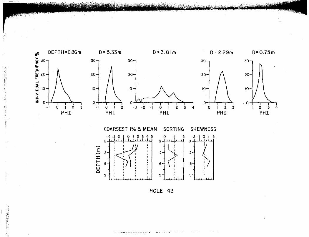
'k~i..f-9;>1·. ,~: h'11¥¥:it 1~:;;s;~~L;.~,;
* DEPTH =6.86m D = 5.33m D=3.Blm D = 2.29m D=0.75m
>- 30-, o 30-, z 30-, 30-, 30 II.I :) 0
\'> ~ 20--j I\ 20-j / I 20-, 20--l {\ 20 ,'; :(" lL } _J
<(
~ 10-, I \ 10-, I \ 10-, I\ 10--l I \ 10
> c z o I' I I "I I o I I
I I I 0 f y I I I I I :::,,
I I 01 • I I > I .o
- I 0 I 2 3 - I 0 I 2 -3 -2 -1 0 I 2 3 4 0 I 2 3 I 2 3 4
PHI PHI PHI PHI PHI
\\: COARSEST 1°/o 8 MEAN SORTING SKEWNESS
- 4 -3 -2 -I O I 2 3 4 5 0 I 2 -2 -1 0 I 2 0
<Sf 0 0
~
* h .5 3 3 3 ::c I-
6 6 6 a_ w . . 0 :
9 : I sL I 9
HOLE 42
.·-:,,;;;,:~~ .. -.-..::. ~~ ..

118
Areal Trends and Paleaflaw Conditions
The outburst-deposited sediments show a fining trend away from
the Lake Souris inlet towards the northern, deeper portions of the
basin (Fig. 25, 26 and 29). The coarse-grained sediment at the apex
of the northern fan (Fig. 4) also is evident from the textural
analyses (Fig. 25 and 26). The third-order trend surface of the
averaged mean (Fig. 26) is useful to view the patterns of
sedimentation because the pattern is not obscured by local influences.
The outburst sediments in Lake Souris, as are any sediments, are
directly related to the hydraulic characteristics of the flows from
which they were deposited. Accordingly, a perusal of the sediment
patterns demonstrates that the highest energy flows occurred at the
inlet ta Lake.Souris and were concentrated from the inlet in an
elongate pattern along the Souris spillway (Fig. 25 and 26).
Interpretation of fan development is strongly influenced by the
presumed hydraulic conditions that formed it. Although several
hydraulic characteristics of the flow conditions are uncertain, a
simple hydraulic analysis of the flows is presented, based on a grain
suspension criterion. A grain-suspension criterion defines the
threshold conditions required for suspension of grains. The purpose
of this hydraulic evaluation is to obtain information that may aid in
the interpretation of fan development, not to speculate on precise
paleoflow conditions. The approach used follows the methodology Komar
(1985) used in a study on the hydraulic.interpretation of turbidites.
In that, he discussed the validity of the approach and the conditions
to which it is applicable.
• • !f

119
Inherent in the use of a grain-suspension criterion to estimate
paleoflow conditions is the assumption that the sediments were
transported in suspension and underwent little or no traction
transport upon deposition. These conditions are presumed to have been
met for the outburst sediments of Lake Souris: arguments for
transport by suspension have already been presented and the rapid
sedimentation associated with the outburst event probably would have
precluded significant transport of grains subsequent to initial
deposition.
The density of the fluid is important to hydraulic studies
because the value is required in most hydraulic formulas and because
density is an indicator of flow type (Newtonian or non-Newtonian).
The fluid density of the Lake Regina outburst flows in the Souris and
Des Lacs spillways is estimated to have been as high as 1.3 gm cm3
(Lord and Kehew, 1987). The density of the outburst flows, upon
entering Lake Souris, probably would have decreased some, but, because
fluid mixing is inhibited in density currents (Albertson and others,
1950), the decrease may have been small. The ensuing calculations are
made using a fluid density value of 1.2 gm cm3; this is comparable to
that estimated by Lord and Kehew (1987) and to estimates used for
turbidity currents (Hein, 1982).
The grain-suspension criterion used in this study is
Wm / U* : 1. 0 , (1)
where Wm is the grain settling velocity and U* is the shear velocity
of flow (Komar, 1985). The shear velocity 1s represented as
U*; (T / p) 0•5 (2)
" " ,, " "
" In ,, " " " "'
" .,

120
where Tis the frictional drag or boundary shear stress and pis the
fluid density {see Komar, 1985). This criterion has been widely used
in studies of turbidites {Komar, 1985) and in other hydraulic studies
of sand {Middleton, 1975; Middleton and Southard, 1984). Combining
equations (1) and (2) yields
T " P 2
{ Wm) • ( 3)
The grain-suspension criterion (eq. 3) was applied to the values
on the contoured map of the averaged coarsest one percent (Fig. 25b)
for three reasons: (1) In Komar's (1985) study, the hydraulic
evaluation of the coarsest particles in samples showed the best
agreement with hydraulic estimates based on sedimentary structures.
(2) The vertically averaged textural data for Lake Souris basin
sediments were used to obtain a rep\esentative overview of the flow
conditions in Lake Souris. Because the majority of the holes exhibit
little textural variation, inaccuracies introduced by averaging should
be minimal. Although this approach will not yield hydraulic
information as precise as any one set of samples treated individually,
it is more valuable in evaluating fan development because it uses all
samples. (3) The averaged coarsest one percent do not include the
coarse-grained spike samples presumably deposited by high-density
flows. Inclusion of samples deposited by non-Newtonian flows may
invalidate the approach used.
The results of paleohydraulic calculations are shown in Figure
37. The values on the map are presented in terms of mean velocity, u,
mainly because velocity values are more easily visualized than shear
stresses. The boundary shear stress is related to mean velocity by
,· IL 1-.,,. ,-.
ii .,
' " " .,

I ' i
II ·
•f ,.
t •., 11
~·11
121
Figure 37. Contour map of paleovelocities in Lake Souris based upon the application of equations (3) and (4) to the averaged coarsest one percent textural data (see Fig. 25b). Values in parentheses are the percentage of initial1influx velocity, assuming an initial velocity of 260 cm s . The contour intervals are irregular. A conversion table from velocity to shear stress, based on equation (4), is given beneath the map.
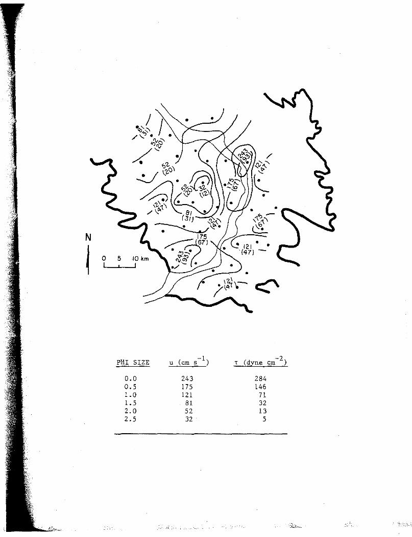
,
• • <, ~ ,1. '\'
l '-"'•
. c;::-. (47) -
PHI SIZE -1 -2 u (cm s ) T (dyne cm )
0.0 243 284 0.5 175 146 l.O 121 71 1.5 81 32 2.0 52 13 2.5 32 5
·:b.~,-

l ;
123
T = Cf p u2 (4)
where Cf is a dimensionless drag coefficient taken to be equal to
about 0.004 (Komar, 1985). The precise value of Cf is not known, thus
more confidence should be placed on the T values provided in the
conversion table, based on equation (4), beneath the map on Figure 37.
The paleovelocity estimates demonstrate a pattern of decreasing
velocity away from the inlet and from the spillway, as expected. If
it is assumed that the initial influx velocity of the outburst flows -1
was 260 cm s as calculated by Komar (in press, b), then the
paleovelocity estimates may be recalculated as a percentage of the
initial influx velocity. The percentage values are given in
parentheses on Figure 37. These calculations indicate a relatively
small decrease in velocity along the spillway with more rapid
decreases to the sides.
The theory of fluid jet flow has been applied to the formation of
deltas (Bates, 1953). Jet-flow theory is useful in predicting the
effects of density differences between fluids and of initial influx
velocity on the mixing patterns of the jet upon entering a standing
body of water. The velocity reduction patterns indicated by the Lake
Souris sediments (Fig. 37) are consistent with what is expected for a
jet of high density and high discharge (Bates, 1953; ~right, 1977).
Depositional Model
A model of deposition for the Glacial Lake Souris sediment fan
constructed by the flows of the Glacial Lake Regina outburst may now
be considered. Data concerning the stratigraphy and sedimentology of
' ' ' "' '

[ ,
i
124
the outburst-deposited sediments have been presented, as well as
interpretations of several aspects of their origin, development, and
interrelationships. At this juncture it is beneficial to review some
major points that a depositional model for the Lake Souris fan must
embody. First, there is little evidence from the sedimentary record
that flow energy decreased with duration; most vertical sections
coarsen upward. Also, only a relatively small amount of silt-size
sediment was deposited by the outburst in Lake Souris and virtually no
clay-size sediment, yet most of the sediment delivered to Lake Souris
by the outburst flows was silt and clay size (Table 1). Second, the
majority of holes sampled have simple textural patterns, indicating
little migration of the areas where specified depositional processes
were active. _Third, the depositional processes interpreted to have
been active in the formation of the fan are braided rivers, low
density turbidity currents, and high-density turbidity currents or
modified grain flows. Braided river deposits occur along the Souris
spillway, especially near the inlet, and at the mouths of the overflow
channels (Kehew, 1982) along the western edge of Lake Souris (Fig.
38). The high-density flow deposits occur away from the margins of
the lake basin and the low-density flow deposits are widespread
throughout the basin (Fig. 38).
The coarse-grained sediments of Lake Souris may be explained by
various types of depositional processes resulting from rapid
sedimentation by sediment-laden outbursts flows that catastrophically
inundated the Lake Souris basin. The three depositional processes
responsible for the Lake Souris fan probably were all active

I
!
"fi I
~ : ' ' ij·1,;
11,~ : .
·r•· (r ·
125
Figure 38. Generalized distribution of deposits by the three depositional processes listed. The boundaries are drawn based on sample hole lithologies the geologic map of Glacial Lake Souris (Appendix D).

'
N
i 0 10km
I, .:/)! LOW-DENSITY TURBIDITY FLOW DEPOSITS
0 HIGH-DENSITY FLOW DEPOSITS
CS] BRAIDED RIVER DEPOSITS

1 1
l 'i
- ·- -------------------
127
concurrently for most of the duration of the outburst. Sedimentation
at the inlet was primarily by a braided river; much of the deposition
occurred above the pre-outburst water level of Lake Souris (Fig. 28,
29, and 31). This part of the fan is envisioned to have been similar
to a 'supraaquatic delta', a term used by Hjulstrom (1952) to describe
glaciofluvial sequences he studied in Scandinavia and Iceland.
Supraaquatic deltas accumulate above lake level and result from rapid
sedimentation and high competence (Church and Gilbert, 1975). They
may be considered to be a transitional form between high slopes
upstream and the low slope of the river mouth (Axelsson, 1967).
The braided river deposits on the north side of the till high
probably formed in a similar manner as those near the inlet. The till
high may have .at first been a barrier to outburst flows that
subsequently was cut, thereby initiating similar events in the
northern fan as the southern fan.
The outburst flows, upon entering Lake Souris, probably caused
continuous, rapid sedimentation from both high- and low-density
currents. The constancy of the processes is attested to by the
simple, non-repetitive sediment sections. For example, most of the
high-density flow deposits occur at the bottom of the outburst
deposited sections and are not repeated above (Fig. 22b). The
majority of the density current deposits, therefore, were probably not
generated by discrete slumps as is most common in glacial lakes and on
submarine fans (Smith and Ashley, 1985; Shanmugam and Moiola, 1988).
Exceptions to this do occur, such as previously discussed in
conjunction with hole 42 (Fig. 36). lolhether the high-density flows

l ··.·.i·l·
..
'
.'· •.. ,: ..
t' • i/
' '
128
resulted directly from the initial inflow or from continuous
avalanching due to rapid sedimentation (Allen, 1968) is uncertain.
Low-density turbidity currents became more predominant throughout
the duration of the outburst flows, as evidenced by sedimentary record
and inferences based on the sediment concentration hydrograph for
outburst and geology of the spillways (summarized earlier). High
density flow deposits still occurred, but were less common and
probably were slump-generated (e.g., hole 42). A diagrammatic
representation of the locations of the different types of deposits,
which summarizes what has been discussed above, is given in Figure 39.
The duration of the Lake Regina outburst is estimated to have
been very short, no more than a few weeks (Kehew and Clayton, 1983);
the brevity of this event is also indicated by the deficiency of silt
size and clay-size particles among the outburst sediments, but which
were abundant in the flows. From this, it may be concluded that the
retention time of outburst flows in Lake Souris must have been short
and, accordingly, the catastrophic drainage of Lake Souris must have
been triggered before the majority of the silt- and clay-size sediment
had sufficient time to settle out. Once the drainage of Lake Souris
began, conditions would have changed from ponding to through-flow,
thus permitting the passage of the silt and clay through the basin.
The geomorphologic effects of the drainage of Lake Souris will be
discussed in the following section.
There is no evidence that Lake Souris reformed after the drainage
induced by the outburst flows. If Lake Souris had reformed, braided
river deposits near the inlet would have obscured the trench-shape

'I •
I
!~
129
Figure 39. Diagrammatic longitudinal section through the Lake Souris basin depicting relationships of sediments deposited by different depositional processes.
d
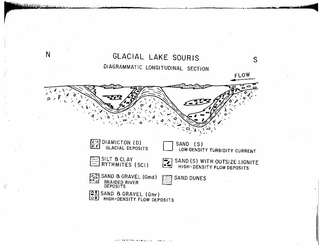
r·lillilV,-V> ... ·"
N
. ,.
- ----· • r n\' e·r· ~
GLACIAL LAKE SOURIS DIAGRAMMATIC LONGITUDINAL SECTION
.·~,-~·r::.·-,~~ 'l"J.~·~~t~-~-
s FLOW
fi:a) DIAMICTON ( D) IEiJ GLACIAL DEPOSITS D SAND (S)
LOW-DENSITY TURBIDITY CURRENT
Fl SILT S CLAY 8 RYTHMITES (SCI)
~ SAND (S) WITH OUTSIZE LIGNITE ~ HIGH-DENSITY FLOW DEPOSITS
~ SAND 8 GRAVEL (Gmd) fY</ SAND DUNES EE BRAIDED RIVER ;,-,:_:
DEPOSITS
~ SAND 8 GRAVEL (Grnr) ~ HIGH-DENSITY FLOW DEPOSITS
~ ... ,,,~--=~.,., .. ~ ....... - -----

•
131
form of the spillway, and fine-grained sediments typical of glacial
lakes would overlie the outburst sediments (Liverman, 1987). It also
may be concluded, then, that the inundation of Lake Souris by the
glacial-lake outburst was the last glacial event to directly affect
Lake Souris .
h,
1/!I ,.
l'~ .. ,,
GEOMORPHOLOG!C EFFECTS OF THE OUTBURST
The surface of the Lake Souris plain and the outlets of the lake
both were markedly affected by the events resulting from the
inundation of the basin by flows from the Lake Regina outburst. Prior
to the arrival of the outburst discharges in Lake Souris, there was no
active outlet to the north so that, initially, discharges from Lake
Souris were through the Girard Lake spillway (Fig. 3). The morphology
of the Girard Lake spillway indicates that it conveyed only relatively
small discharges for a short duration (see Kehew and Clayton, 1983);
consequently, the northern outlet of Lake Souris, which leads to
Glacial Lake Hind (Fig. 2), ·must have become active soon after arrival
of the outburst flows. Once incision of the northern outlet began,
flaw probably became more directed towards the north and flows to the
topographically higher southeast portion of the lake basin may have
ceased. This is supported by the presence of channel scars to the
north and north-northwest and the absence of them to the east (Fig.
5).
The response of the water level of Lake Souris to the continued
incision of the Souris-Hind spillway (the northern outlet) must remain
speculative. The water level in Lake Souris presumably continued to
rise in response to the great influx of outburst waters until the
132
" " ,, Ii
" i! " ,, ,, " " '

1
133
Souris-Hind spillway was incised sufficiently to permit an equal
discharge from Lake Souris. The water level of Lake Souris must have
begun to fall when the easily eroded Souris-Hind spillway enlarged so
that the discharge rate was greater leaving Lake Souris than entering.
The sediments of the Lake Souris plain are incised by the Souris
spillway, except at the basin center, over much of its length (Figs. 5
and 32; Appendix D); because this channel is very large (comparable to
the Souris spillway upstream from Lake Souris), substantial discharges
must have formed it. It may be concluded, then, that although
discharge through the Souris-Hind spillway was greater than that
entering Lake Souris, causing the lake level to drop and expose
portions of the basin floor, the outburst flows entering the lake were
still great enough to carve large channels. Before incision of the
floor of Lake Souris was complete, discharges from the outburst of
Lake Regina had tapered off to negligible rates.
The information on fluctuations in lake level may be used to
explain the development of channels associated with the outburst
event. The channels existing at the onset of the outburst were the
overflow channels entering Lake Souris on the western edge and the
Girard Lake spillway to the southeast (Fig. 40). As the northern
outlet enlarged and lake level began to decline, exposing some of the
basin floor, incision by the Souris spillway progressed towards the
basin center concurrently with headward knickpoint migration of the
Souris-Hind spillway (Fig. 40). This migration stopped when the
influx of outburst waters stopped. The result of this pattern of
channel development is a consistent increase in relief from the basin
: ,., lif'i
qi~'] ,,
IP'
•f ' r· ...
134
Figure 40. Diagrammatic model of incision migration by the Souris spillway into the Lake Souris basin in response to falling lake level. The onset the outburst is indicated by the most extensive lake level (Lo) and channels (Co). Higher numbers indicate succeeding stages as channels migrated towards the center of the basin concurrently with drops in lake level.
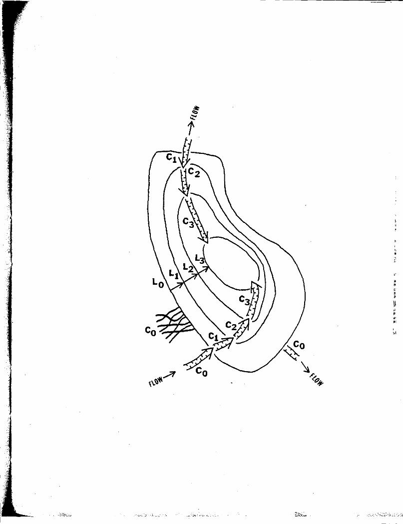
\·, I
'
• ' w
' '
' "'

136
center towards the margins of the lake (Fig. 33). The lake had to
have completely drained because the northern outlet is incised below
the lowest elevation in the lake basin (Kehew and Clayton, 1983).
The erosional capacity of the flows during drainage of Lake
Souris also is attested to by the large area of eroded till, up to 20
km wide, in the northern portion of the lake basin (Fig. 5; Appendix
D). This area is covered with dozens of what appear as shallow
channels, which are generally oriented towards the Souris spi]lway. A
boulder lag that becomes more concentrated towards the spillway is
present over much of this area (Lord, 1988). The area is analogous to
the outer zone described by Kehew and Lord (1986), probably
representing an early stage of spillway development. An anomalous
feature of this area is that the general slope of the eroded surface
rises to the north, rising about 15 mover a 30 km distance (The
actual rise probably was somewhat less during the outburst because of
differential isostatic rebound since the event). There must have been
a large head of water to provide the energy slope necessary to drive
fl ow upslope.
Other geomorphologic effects, direct and indirect, of the Lake
Regina outburst include: 1) the initiation of events similar to those
in Lake Souris in the downstream Lake Hind, and 2) the formation of
sand dunes over much of the lake basin during the Holocene. Both of
these have been described by Kehew and Clayton (1983).
• ' '
I ;
FURTHER STUDY AND IMPLICATIONS
In this paper the sedimentology and stratigraphy of the outburst
sediments in the Glacial Lake Souris basin have been described and
interpreted. During the Pleistocene, hundreds of channels were deeply
incised by glacial-lake outbursts along the midcontinent margins of
the Laurentide Ice Sheet (Kehew and Lord, 1987). Whereas flood waters
initially were dumped into downstream glacial lakes, such as Lake
Souris, the ultimate destination of outburst flows was the ocean.
Because many of the discharges of major outbursts funneled into the
Mississippi River, sedimentation by outburst flows probably dominated
deposition on the Mississippi fan and Louisiana offshore during
glacial intervals (Kehew and others, 1986; Kehew and Lord, 1987).
It is appropriate to consider the applicability and implications
of the conclusions drawn from the study of Lake Souris to other areas.
To do this, one must first consider what is fundamental about the
outburst deposits that will permit their recognition in geologic
settings that may differ from those of Lake Souris. Because the
outburst flows inundated Lake Souris after active glaciation in the
area, the resulting deposits and patterns of sedimentation are not
obscured by the presence of normal glacial outwash deposits. The most
striking characteristics of the outburst sediments are 1) the
137
l; '
' ' . "
n

138
constancy of vertical sections, commonly up to 10 m thick, indicating
little change in flow conditions, 2) the pervasiveness of anomalously
coarse-grained sediments over most of the lake basin, and 3) the
abundance of high-density flow deposits formed by continual
sedimentation rather than discrete slump-generated deposition.
Fans formed by outburst flows have been recognized in Glacial
Lakes Agassiz, Dakota, and Hind (Fig. 2) because they occur at the
mouths of glacial-lake spillways and because their surficiaT geology
is similar to that of Lake Souris (Kehew and Clayton, 1983; Kehew and
Lord, 1987). The recognition of outburst deposits on the marine
offshore is considerably more complicated. Nonetheless, on the
Mississippi Fan, discrete, large fresh-water pulses indicated by
negative oxygen isotope anomalies (Emiliani and others, 1978; Leventer
and others, 1982), anomalously coarse-grained sediments, and
channelized density-flow deposits (Feeley and others, 1985) suggest
that sedimentation from glacial-lake outbursts in the midcontinent
region did affect the offshore (Kehew and others, 1986). Also, deep
sea gravels in the Cascadia Channel, off the northwest coast, are
interpreted to have been deposited by high-density turbidity currents
that were transported hundreds of kilometres offshore by outburst
flows from Glacial Lake Missoula (Griggs and others, 1970).
If detailed studies of offshore fans in North America, Europe,
and Asia, can differentiate glacial-lake outburst deposits from normal
glacial-meltwater deposits, the relative roles of each as a
glaciofluvial process may be assessed. Furthermore, if glacial-lake
outbursts are found to be a significant process on a global scale,
" " ,1
"' ,,,
~: J; IP'
" ,II

I ,
I 1 "
l I
139
interpretation of ice volumes and climatic variations based on oxygen
isotope data should be reevaluated. Glacial lakes, by temporarily
storing glacial meltwater (up to hundreds of years), act as a buffer
between glacier melting and delivery of that meltwater to the ocean.
Also, the possibility exists of misinterpreting large, negative
isotopic peaks as sudden climatic warmings rather than one or more
large glacial-lake outbursts.
Information from this study may also be useful in interpreting
parts of the Martian surface. Large outflow channels probably formed
by catastrophic floods, yet the sinks for the floods lack features
typical of lakes (Baker and Kochel, 1979). Broad, light-albedo
patches at the mouths of some outflow channels may represent fan
deposits (Bake~ and Kochel, 1979) that are genetically similar to that
of Lake Souris.
SUMMARY AND CONCLUSIONS
The purpose of this study has been to demonstrate the effects of
a glacial-lake outburst on a lake that received the outburst flows,
specifically, the effects of the Glacial Lake Regina outburst on Lake
Souris. This topic previously has not been examined in detail. Study
of the sedimentology and stratigraphy of the Lake Souris basin
sediments, the geomorphology of the lake plain, and previous work
related to the subject each demonstrate that the Lake Regina outbur$t
had a dramatic. effect on Lake Souris. Each of these approaches
independently supports the following general conclusions: the
outburst flows were large of magnitude, representing a much higher
energy hydrologic regime than immediately prior to it, the outburst
was short-lived, and the sediment concentrations in the outburst flows
were high. Specific conclusions of this study are:
1. The sediments of the Lake Souris basin are composed of five
lithofacies: diamicton, laminated silt and clay, matrix-rich gravel,
matrix-deficient gravel, and sand.
a) The diamicton and the laminated silt and clay lithofacies
underlie the outburst sediments. The diamicton lithofacies consist of
unsorted to very poorly sorted gravelly sand, silt, and clay,
deposited directly by the glacier or by mass movement off the ice.
140
" ii :1
" " " " " "
141
The laminated silt and clay lithofacies represents deposition in a
low-energy lake environment, probably isolated glacial lakes that had
coalesced into one larger lake by the time of the outburst.
b) The outburst sediments are comprised of three lithofacies:
matrix-rich gravel, matrix-deficient gravel, and sand. The matrix
rich gravel lithofacies consists of lignite-bearing, poorly sorted
gravels w.ith a fine-grained matrix. These gravels tend to occur at
the base of the outburst sediments and are limited to the inlet area
and adjacent to the Souris spillway. The matrix-deficient gravel
lithofacies typically has a coarser grained matrix than the matrix
rich gravels and no lignite. This facies occurs at and near the
ground surface adjacent to the Souris spillway. Sand, the most
widespread and abundant lithofacies, tends to occur on top of other
lithofacies. Most sand contains some lignite particles; at depth,
outsize lignite clasts are common in the sand.
2. Two coarse-grained sediment fans, with gravel apexes, are
apparent in the outburst sediments, one at the Lake Souris inlet and a
smaller one near Towner just north of a till high. Sediments
generally show a gradual fining away from the fan apexes to the
northwest. Most outburst sediments are well sorted to moderately well
sorted fine to medium sand. Vertically, most outburst sediments
become coarser upward; the most prominent exception is the sediments
immediately adjacent to the Souris spillway that have gravel at the
base and are sand at the top.
3. Three major depositional processes probably are responsible
for deposition of the outburst sediments: braided rivers, low-dens i ty

-:I,-
142
turbidity currents, and high-density turbidity currents or modified
grain flows. Braided river deposition occurred primarily near the
inlet and migrated basinward as the flood continued. Most high
density flows resulted directly from the influx of outburst flows or
from continuous avalanching due to rapid sedimentation. Low-density
turbidity currents occurred for the entire duration of the outburst
and were caused by the continuous influx of sediment-laden flows and
by residual currents from high-density flows. Low-density turbidity
currents were the dominant sedimentary process during the outburst.
4. Outburst sedimentation in Lake Souris was short-lived. Most
of the sand- and gravel-size sediment delivered to Lake Souris by the
outburst was deposited in the basin. Most silt- and clay-size
sediment, however, was transported through the basin because drainage
of Lake Souris was occurred before the silt and clay had time to
settle out from suspension.
5. The water level in Lake Souris declined as the northern
outlet, the Souris-Hind spillway, conveyed more water than was
entering the inlet. Incision of the lake bottom by the Souris
spillway occurred concurrently with fdl ling lake- level; incision
stopped when the Lake Regina outburst flows became negligible.
It is appropriate to reiterate some limitations of this study in
order to keep the results in perspective. Foremost, only a relatively
small number of sample holes was made for a large study area. The
influence of this limitation is that major trends are emphasized by
the data; small-scale complexities are obscured. Thus, areal patterns
presented are probably much more simple than would be obtained if more
:r,1 111 jl
ii " .,, ~'

143
sample holes were used, especially because of the irregular pre
outburst surface. Although this limitation probably does not
significantly affect the interpretation of sedimentary processes, it
may affect specific interpretations about Lake Souris geology.
Detailed studies of a small part of Lake Souris would help clarify
possible discrepancies.
An additional limitation of this study is that only a few
undisturbed sedimentary structures were observed. Complete
descriptions of sedimentary structures associated with the different
lithofacies probably would have permitted more detailed (and possibly
more accurate) interpretations of sedimentary processes. The best way
to observe sedimentary structures would be in an excavation. The
depth of such excavations would be limited by the commonly high
groundwater table in the Lake Souris plain,
',1
,, " " "

I .'
f 1 I
'
I .;
,. j
I s~ I/
APPENDICES
:1
'" •• ,,.

..
' .
I
I I 1
- -~-------====-
APPEND IX A
Locations and descriptions of samples collected for this study. Diamictons are noted but not described; see Remple (1987) for their descriptions. The N-File numbers given for each hole are unique labels used in a near-surface data set maintained by the North Dakota Geological Survey. -
Key to Abbreviations
vfS • very fine sand fS • fine sand mS • medium sand cS • coarse sand vcS • very coarse sand Gv • gravel
saa • same color as above lam. • lamination lams. • laminations mod. • moderately
I
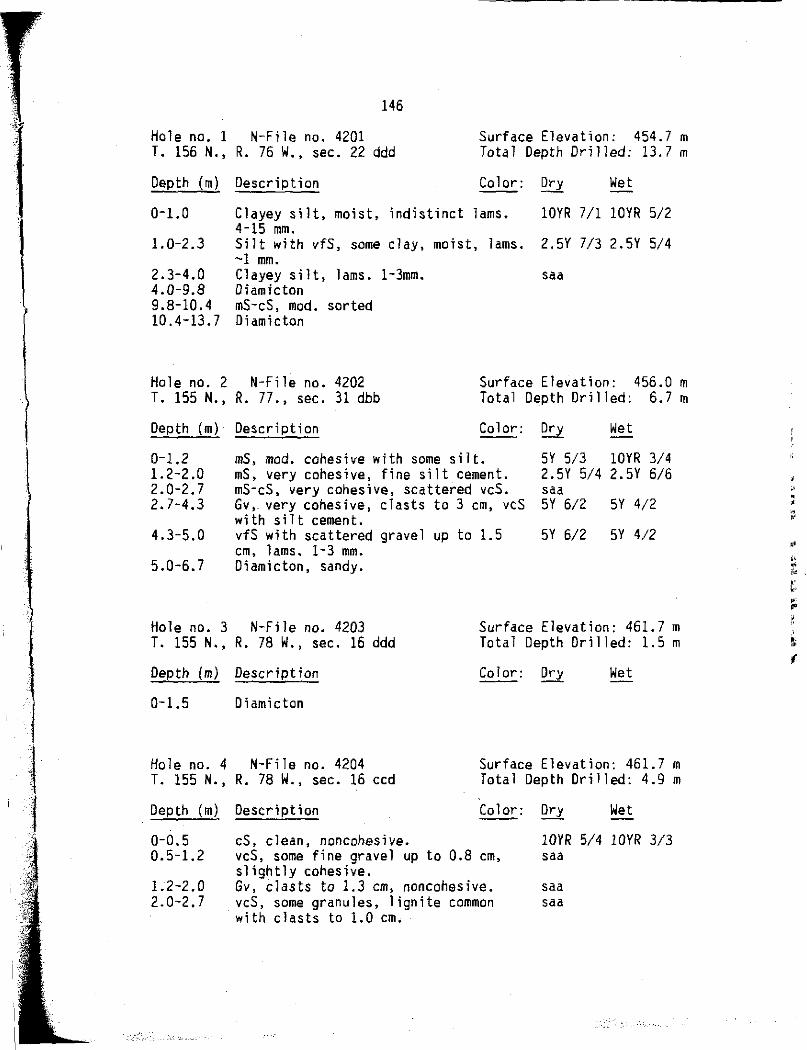
146
Hole no, 1 N-File no. 4201 T. 156 N., R. 76 W., sec. 22 ddd
Surface Elevation: 454.7 m Total Depth Drilled: 13.7 m
Depth (m) Description Color: Dry Wet
0-1.0 Clayey silt, moist, indistinct lams. lOYR 7/1 lOYR 5/2 4-15 mm.
1.0-2.3 Silt with vfS, some clay, moist, lams. 2.5Y 7/3 2.5Y 5/4 -1 mm.
2.3-4.0 Clayey silt, lams. 1-3mm. saa 4.0-9.8 Diamicton 9. 8-10. 4 mS-cS, mod. sorted 10.4-13.7 Diamicton
Hole no. 2 N-File no. 4202 T. 155 N., R. 77., sec. 31 dbb
Surface Elevation: 456.0 m Total Depth Drilled: 6.7 m
Depth (m) Description Color: Dry Wet
0-1.2 1.2-2 .o 2.0-2.7 2.7-4.3
4.3-5.0
5.0-6.7
mS, mad. cohesive with some silt. mS, very cohesive, fine silt cement. mS-cS, very cohesive, scattered vcS. Gv,. very cohesive, clasts to 3 cm, vcS with silt cement. vfS with scattered gravel up to 1.5 cm, lams, 1-3 mm. Diamicton, sandy.
SY 5/3 lOYR 3/4 2.5Y 5/4 2.5Y 6/6 saa 5Y 6/2 SY 4/2
5Y 6/2 SY 4/2
Hole no. 3 N-File no. 4203 T. 155 N., R. 78 W., sec. 16 ddd
Surface Elevation: 461.7 m Total Depth Drilled: 1.5 m
Depth (m) Description Color: Dry Wet
0-1.5 Diamicton
Hole no. 4 N-File no. 4204 T. 155 N., R. 78 W., sec. 16 ccd
Surface Elevation: 461.7 m Total Depth Drilled: 4.9 m
Depth (m) Description Color: Dry Wet
0-0.5 0.5-1.2
1.2-2.0 2.0-2.7
cS, clean, noncohesive. vcS, some fine gravel up to 0.8 cm, slightly cohesive. Gv, clasts to 1.3 cm, noncohesive. vcS, some granules, lignite common with clasts to 1.0 cm.
lOYR 5/4 lOYR 3/3 saa
saa saa
•' ' ' ;) ,. ,. t ..

i l l !
147
Hole no. 4 continued:
Depth (m) Description Color: Ory Wet
2.7-3.7 Gv, matrix of cS, outsize lignite saa clasts common, up to 5 cm. Bottom 0.3 mis lignite gravel.
3.7-4.9 Diamicton
Hole no. 5 N-File no. 4101 T. 155 N., R. 78 W., sec. 13 ddd
Surface Elevation: 463.6 m Total Depth Ori lled: 16.2 m
Depth (m) Description Color: Dry Wet
0-0.3 0.3-5.0
mS, noncohesive, well sorted. lOYR 5/3 lOYR 3/2 Gv, noncohesive, some caliche at 4 m, saa clasts to 6 cm.
5.0-5.8 cS, with scattered gravel to 3 cm, 2.5Y 6/2 2.5Y 4/2
5.8-6.6 6.6-8.1
clean. mS-cS with scattered Gv to 5 cm. saa fS with scattered Gv to 2 cm, outsize saa lignite common, obscure lams. -1 mm in fS ..
8.1-9.6 vfS, noncohesive, lams. -1 mm. saa 9.6-11.9 fS, well sorted except for outsize saa
lignite to 0.6 cm. 11.9-12.6 vfS with silt, lignite abundant. saa 12.6-13.4 Silt, lignite abundant. saa 13.4-14.2 vfS with silt, lignite abundant. saa 14,2-14.7 Diamicton, massive 14.7-14.8 Silt and clay couplets with light and saa
dark lams. 0.2-8.0 mm. 14.8-14.9 Diamicton, layered, -1 cm thick. 14.9-16.2 Diamicton, massive.
Hole no. 6 N-File no. 4205 T. 155 N., R. 76 W., sec. 18 ccc
Surface Elevation: 458.9 m Total Depth Drilled: 6.7 m
Depth (m) Description Color: Ory Wet
0-2.7
2.7-3.5 3.5-5.0
5.0-6.7
mS, mod. to poorly sorted, lOYR 6/3 lOYR 3/3 noncohesive, scattered Gv to 0.8 cm. fS, we 11 sorted, clean, lignite common saa mS, clean, noncohesive, outsize saa lignite common, up to 1.3 cm. Diamicton, layered from 5.0-5.5 m, massive below, clasts to 1 cm.
• ,, " e
,, t :::

148
Hole no. 7 N-File no. 4206 T. 156 N., R. 77 W., sec. 25 dda
Surface Elevation: 448.9 m Total Depth Drilled: 12.8 m
Depth (m) Description Color: Ory Wet
0-1.7 mS, mod. sorted, obscure lams. 1-10 mm, mod. cohesive.
1.7-4.5 mS, mod. to well sorted, noncohesive 4.5-5.1 fS, well sorted, lignite common,
obscure lams. -1-6 mm, slightly cohesive.
5Y 5/3 5Y 4/3
2.5Y 3/2 2.5Y 2/0 5Y 5/3 5Y 3/3
5.1-9.7 mS-cS, mod. sorted, slightly cohesive, obscure lams. 1-5 mm.
SY 6/3 5Y 4/3
9.7-11.1 Gv, clasts up to 3 cm, clean, very poorly sorted.
11.1-12.8 Diamicton.
saa
Hole no. 8 N-File no. 4207 T. 156 N., R. 77 W., sec. 32 aaa
Surface Elevation: 461.7 m Total Depth Drilled: 18.9 m
Depth (m) Description Color: Dry Wet
0-2.0 fS,. mod. to well sorted, noncohesive, 2.5Y 4/2 2.5Y 2/2 scattered vcS at 1.5-2.0 m.
2.0-3.6 vfS to fS, mod. to well sorted, 2.5Y 7/4 2.5Y 4/4 slightly cohesive, obscure lams. 1-2 mm marked by lignite concentrations.
3.6-6.8 mS, well sorted, clean, lignite 5Y 5/1 SY 3/2 common, cS to vcS at 6.3 to 6.8 m.
6.8-8.0 vfS, some silt, indistinct lams. 1-5 saa mm, mod. to poorly sorted.
8.0-11.2 fS, mod. well sorted, lignite saa particles up to 6 mm, slightly cohesive, lams. 2-12 mm thick.
11.2-16.5 silt and clay, alternate dark and saa light lams. 0.2-1.2 mm, well con so 1 idated.
16.5-18.9 Diamicton.
Hole no. 9 N-File no. 4208 T. 156 N., R. 78 W., sec. 26 bba
Surface Elevation: 461.7 m Total Depth Drilled: 15.8 m
Depth (ml Description Color: Ory Wet
0-2.7 mS, very well to well sorted, unconsolidated except slightly at surface, lignite common, outsize lignite up to 5 mm.
2.5Y 6/3 2.5Y 4/3
-. .;. ... ,
,,,
'
,,
,. " •
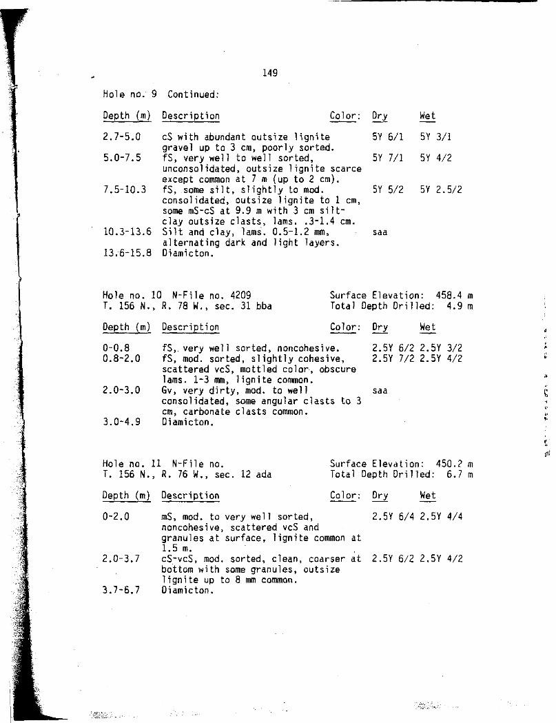
.. :j
149
Hole no. 9 Continued:
Depth (m) Description Color: Dry Wet
2.7-5.0 cS with abundant outsize lignite 5Y 6/1 5Y 3/1 gravel up to 3 cm, poorly sorted.
5.0-7.5 fS, very well to we 11 sorted, SY 7 /1 SY 4/2 unconsolidated, outsize lignite scarce except common at 7 m (up to 2 cm).
7.5-10.3 fS, some silt, slightly to mod. SY 5/2 5Y 2.5/2 consolidated, outsize lignite to 1 cm, some mS-cS at 9.9 m with 3 cm silt-clay outsize clasts, lams .. 3-1.4 cm.
10.3-13.6 Silt and clay, lams. 0.5-1.2 mm, saa alternating dark and light layers.
13.6-15.8 Diamicton.
Hole no. 10 N-File no. 4209 Surface Elevation: 458.4 m Total Depth Drilled: 4.9 m T. 156 N., R. 78 W., sec. 31 bba
Depth {m) Description Color: Dry Wet
0-0.8 0.8-2.0
2.0-3.0
3.0-4.9
fS,. very well sorted, noncohesive. fS, mod. sorted, slightly cohesive, scattered vcS, mottled color, obscure lams. 1-3 mm, lignite common. Gv, very dirty, mod. to well consolidated, some angular clasts to 3 cm, carbonate clasts common. Diamicton.
2.5Y 6/2 2.SY 3/2 2.5Y 7/2 2.5Y 4/2
saa
Hole no. 11 N-File no. Surface Elevation: 450.2 m Total Depth Drilled: 6.7 m T. 156 N. , R. 76 W. , sec. 12 ada
Depth (m) Description Color: Dry Wet
0-2.0
2.0-3.7
3.7-6.7
mS, mod. to very well sorted, 2.SY 6/4 2.5Y 4/4 noncohesive, scattered vcS and granules at surface, lignite common at 1. 5 m. cS-vcS, mod. sorted, clean, coarser at 2.5Y 6/2 2.5Y 4/2 bottom with some granules, outsize lignite up to 8 mm common. Diamicton.
• '
"
~I

150
Hole no. 12 N-File no. 4102 Surface Elevation: 456.6 m Total Depth Dri]led: 9.8 m T. 156 N., R. 77 W., sec. 1 ccb
Depth (m) Description Color: Dry Wet
0-2.0
2.0-6.5
fS, mod. to well sorted, slightly to SY 6/3 SY 4/3
6.5-7.2 7.2-9.8
mod. cohesive. vfS to fS, noncohesive to weakly 5Y 6/1 5Y 6/4 cohesive, scattered lams. 1-6 mm, scattered lignite particles up to 4 mm. coarse silt, massive, cohesive. 5Y 6/2 5Y 4/2 clayey silt, finely lam., alternating saa dark and light, 0.3-3 mm; light lams. thinner than dark.
Hole no. 13 N-File no. 4103 Surface Elevation: 458.4 m Total Depth Drilled: 28.0 m T. 157 N., R. 77 W., sec. 33 ebb
Depth (m) Description Color: Dry ,let
0-2.0 fS, well sorted, noncohesive, 2.5Y 3/2 2.5Y 3/1 indistinct lams. -2 mm, sediment plastic at 1.5 m.
2.0-3.2 Clayey silt, well-sorted, lams. -1 mm. saa 3.2-25.2 fS and vfS, mod. to well sorted, 5Y 6/2 5Y 3/2
lignite common, scattered obscure lams. 1-3 cm, some lignite is vcS, noncohesive.
25.2-26.7 vfS and some silt, mod. cohesive, saa scattered vcS, poorly sorted.
26.7-28.0 fS, mod. to poorly sorted, scattered saa cs.
Hole no. 14 N-File no. 4211 Surface Elevation: 445.9 m Total Depth Drilled: 6.7 m T. 157 N., R. 76 W., sec. 35 ccc
Depth (m) Description Color: Ory Wet
0-0.8 0.8-2.0
2.0-4.1
fS, mod. sorted, some silt. 2.5Y 5/2 2.5Y 2/2 mS, mod. to poorly sorted, slightly to 2.5Y 6/2 2/5Y 4/3 mod. cohesive. vcS and Gv, Gv to 1 cm at 3.8 m, 2.5Y 6/3 2.5Y 4/4 poorly sorted, lignite and diamicton clasts present, noncohesive.
., " • '
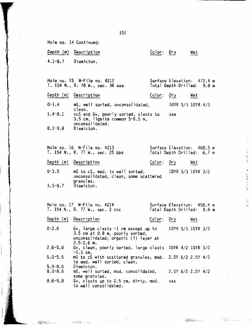
l• •
' r
I '
J . ,
·--~
151
Hole no. 14 Continued:
Depth (m) Description Color: Dry Wet
4.1-6.7 Diamicton.
Hole no. 15 N-File no. 4212 Surface Elevation: 472.4 m Total Depth Drilled: 9.8 m T. 154 N., R, 78 W., sec. 36 aaa
Depth (m) Description Color: Dry Wet
0-1.4
1.4-8.1
8.1-9.8
mS, well sorted, unconsolidated, clean. vcS and Gv, poorly sorted, clasts to 3.5 cm, lignite common 5-6.5 m, unconsolidated. Diamicton.
lOYR 5/3 lOYR 4/3
saa
Hole no. 16 N-File no. 4213 Surface Elevation: 468.5 m Total Depth Drilled: 6.7 m T. 154 N., R. 77 W., sec. 25 bba
Depth (m) Description Color: Ory Wet
0-3.5 mS to cS, mod. to well sorted, lDYR 5/3 lOYR 3/2 unconsolidated, clean, some scattered granules.
3.5-6.7 Oiamicton.
Hole no. 17 N-File no. 4214 Surface Elevation: 458.4 m Total Depth Drilled: 9.8 m T. 154 N., R. 77 W., sec. 2 ccc
Depth (m)
0-2.6
2.6-5.0
5 .. 0-5.9
5.9-8.0 8.0-8.6
8.6-9.8
Description Color: Ory Wet
Gv, large clasts -1 cm except up to lOYR 5/3 lOYR 3/2 3.5 cm at 0.8 m, poorly sorted, unconsolidated; organic (?) layer at 2.5-2.6 m. Gv, clean, poorly sorted, large clasts lOYR 4/2 lOYR 3/2 -1.5 cm. mS to cS with scattered granules, mod. 2.5Y 6/2 2.5Y 4/2 to mod. well sorted, clean. Oiamicton. mS, well sorted, mod. consolidated, 2.5Y 6/2 2.5Y 4/2 some granules . Gv, clasts up to 2.5 cm, dirty, mod. saa to well consolidated.

r l
l I
' l
I I 1
i l j
152
Hole no. 18 N-File no. 4215 Surface Elevation: 461.l m Total Depth Drilled: 6.7 m T. 156 N., R. 75 W., sec. 28 ccc
Depth (m) Description Color: Dry Wet
0-2.7 vfS, some silt, slightly cohesive, SY 6/3 5Y 4/3 mod. sorted, lams. -1 mm at 2.3 m.
2.7-5.9 Silty clay, alternating dark and light SY 6/2 SY 3/2 lams. 0.1-0.7 mm, massive from 4.3-4.8 m, scattered vcS and granules 5.5 to 5.9 m.
5.9-6.7 Diamicton.
Hole no. 19 N-File no. 4104 Surface Elevation: 454.4 m Total Depth Drilled: 6.7 m T. 156 N., R. 75 W., sec. 12 bbb
Depth (m) Description Color: Dry Wet
0-2.0
2.0-6.7
vfS, mod. well sorted, slightly to 2.SY 7/4 2.5Y 5/4 mod. cohesive, silt and clay, lams. 1-2 mm, cohesive. SY 6/2 SY 4/2
Hole no. 20 N-File no. 4111 Surface Elevation: 456.3 m Total Depth Ori 1 led: 18.9 m T. 154 N., R. 73 W., sec. 33 dee
Depth (m)
0-2.0
2.0-2.8
2.8-6.5
6.5-8.0
8.0-12.D
12.0-18.9
Description Color: Dry Wet
mS, clean except silty at surface, 2.SY 7/3 2.5Y 6/5 very well sorted, obscure lams. -1 cm. vcS and Gv up to 3 cm, poorly sorted, saa unconsolidated. mS, mod. well sorted, clean, lignite 5Y 6/2 5Y 4/2 common, outsize lignite up to 2 cm at 3.8 m. vcS and Gv up to 2 cm, poorly sorted, saa noncohesive. · cS-vcS, mod. to mod. well sorted, some saa pebbles 11-12 m. Silt, well sorted, hard, well 5Y 4/1 SY 3/2 i ndura ted, (bedrock?) . ·
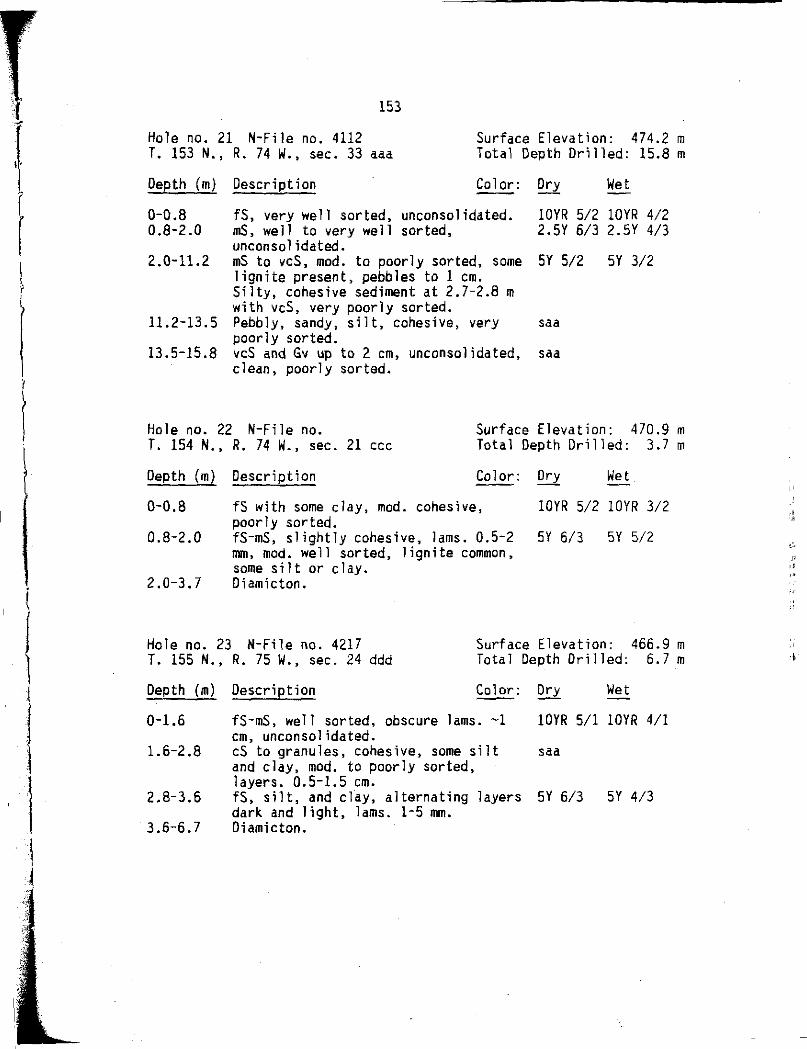
(
I
1 l I
l I i
153
Hole no. 21 N-File no. 4112 T. 153 N., R. 74 W., sec. 33 aaa
Depth (m) Description
Surface Elevation: 474.2 m Total Depth Drilled: 15.8 m
Color: Dry Wet
0-0.8 fS, very well sorted, unconsolidated. lOYR 5/2 lOYR 4/2 0.8-2.0 mS, well to very well sorted, 2.SY 6/3 2.5Y 4/3
unconso 1 idated. 2.0-11.2 mS to vcS, mod. to poorly sorted, some SY 5/2 5Y 3/2
lignite present, pebbles to 1 cm. Silty, cohesive sediment at 2.7-2.8 m with vcS, very poorly sorted.
11.2-13.5 Pebbly, sandy, silt, cohesive, very saa poorly sorted.
13.5-15.8 vcS and Gv up to 2 cm, unconsolidated, saa clean, poorly sorted.
Hole no. 22 N-File no. Surface Elevation: 470.9 m Total Depth Drilled: 3.7 m T. 154 N., R. 74 w., sec. 21 CCC
Depth (m) Description Color: Dry Wet
0-0.8
0.8-2.0
2.0-3.7
fS with some clay, mod. cohesive, lOYR 5/2 lOYR 3/2 poorly sorted. fS-mS, slightly cohesive, lams. 0.5-2 SY 6/3 5Y 5/2 mm, mod. we 11 sorted, lignite common, some silt or clay. Oiamicton.
Hole no. 23 N-File no. 4217 Surface Elevation: 466.9 m Total Depth Drilled: 6.7 m T. 155 N., R. 75 W., sec. 24 ddd
Depth (m) Description Color: Dry Wet
0-1.6
1.6-2.8
2.8-3.6
3.6-6.7
fS-mS, well sorted, obscure lams. -1 lOYR 5/1 lOYR 4/1 cm, unconsolidated. cS to granules, cohesive, some silt saa and clay, mod. to poorly sorted, layers. 0.5-1.5 cm. fS, silt, and clay, alternating layers 5Y 6/3 SY 4/3 dark and light, lams. 1-5 mm. Diamicton.
,, ,,
t'..
" r,~
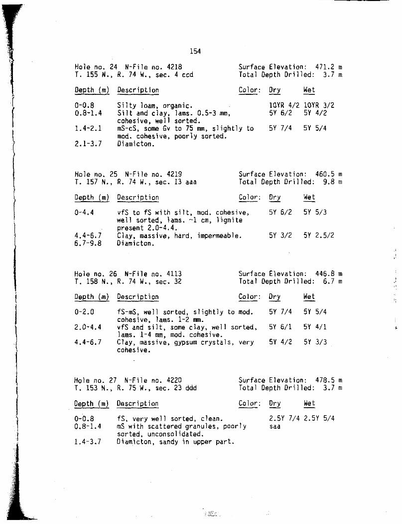
( l
I l
I I
l l
I I j
154
Hole no. 24 N-File no. 4218 Surface Elevation: 471.2 m Total Depth Drilled: 3.7 m T. 155 N., R. 74 W., sec. 4 ccd
Depth (m)
0-0.8 0.8-1. 4
1. 4-2.1
2.1-3.7
Description Color: Dry Wet
Silty loam, organic. Silt and clay, lams. 0.5-3 mm, cohesive, well sorted. mS-cS, some Gv to 75 mm, slightly to mod. cohesive, poorly sorted. Diamicton.
lOYR 4/2 lOYR 3/2 SY 6/2 SY 4/2
SY 7/4 SY 5/4
Hole no. 25 N-File no. 4219 Surface Elevation: 460.5 m Total Depth Drilled: 9.8 m T. 157 N., R. 74 W., sec. 13 aaa
Depth (m) Description Color: Dry Wet
0-4.4 vfS to fS with silt, mod. cohesive, SY 6/2 SY 5/3 well sorted, lams. -1 cm, lignite present 2.0-4.4.
4.4-6.7 Clay, massive, hard, impermeable. SY 3/2 SY 2.5/2 6.7-9.8 Diamicton.
Hole no. 26 N-File no. 4113 T. 158 N., R. 74 W., sec. 32
Surface Elevation: 446.8 m Total Depth Drilled: 6.7 m
Depth (m) Description Color: Dry Wet
0-2.0
2.0-4.4
4.4-6.7
fS-mS, well sorted, slightly to mod. SY 7/4 5Y 5/4 cohesive, lams. 1-2 mm. vfS and silt, some day, well sorted, SY 6/1 SY 4/1 lams. 1-4 mm, mod. cohesive. Clay, massive, gypsum crystals, very SY 4/2 SY 3/3 cohesive.
Hole no. 27 N-File no. 4220 Surface Elevation: 478.5 m Total Depth Drilled: 3.7 m T. 153 N., R. 75 W., sec. 23 ddd
Depth (m) Description Color: Dry Wet
0-0.8 0. 8-1. 4
1.4-3.7
fS, very well sorted, clean. mS with scattered granules, poorly sorted, unconsolidated. Diamicton, sandy in upper part.
,_-;.-,·:· . -.. t-,··.
2.SY 7/4 2.SY 5/4 saa

1 r
r I
I
l
l I t :, 1 '.; i ,·
155
Hole no. 28 N-file no. 4221 Surface Elevation: 471.8 m Total Depth Drilled: 6.7 m T. 154 N., R. 75 W., sec. 29 aaa
Depth (m) Description Color: Dry Wet
0-2.1
2.1-6.7
fS-mS, very well sorted, lOYR 6/4 lOYR 4/3 unconsolidated, obscure lams. Silty clay, gravelly, layered and 5Y 7/3 SY 6/4 massive, very poorly sorted; organic-rich layer (snails, gastropods, plant fragments) at 3.0 m.
Hole no. 29 N-File no. 4114 Surface Elevation: 458.7 m Total Depth Drilled: 12.8 m T. 155 N., R. 75 W., sec. 33 ddc
Depth {m) Description Color: Dry Wet
0-2.l mS, well sorted to very well sorted, lOYR 6/3 lOYR 5/3 some silt, obscure lams. 1-3 mm, slightly plastic.
2.1-3.4 Silty clay, generally massive, small 5Y 4/1 5Y 3/1 pockets of sand 1 cm in diameter.
3.4-12.0 cS-vcS, mod. to poorly sorted, SY 6/2 5Y 5/1 scattered larger clasts present up to 2 cm {mostly lignite), noncohesive.
12.0-12.8 Silty clay, well sorted, cohesive. saa
Hole no. 30 N-File no. 4222 Surface Elevation: 465.4 m Total Depth Drilled: 17.4 m T. 154 N., R. 76 W., sec. 29 aaa
Depth (m)
0-2.0
2.0-2.2
2.2-9.7
9.7-13.5
13.5-17.4
Description Color: Dry Wet
fS-mS, mod. cohesive, mod. to poorly SY 6/2 SY 4/2 sorted. vcS and Gv up to 1 cm, poorly sorted, lignite clasts abundant. fS-mS, well sorted, clean, 5Y 6/1 5Y 4/1 unconsolidated. vfS-fS, mod. sorted, clean, lams. 0.7- saa 2 mm; scattered granules and mod. cohesive at 12.8-13.5. Diamicton.
.. ·,:.:;,, ...
;~.I ,, "' .,

f r t
\ . l
156
Hole no. 31 N-File no. 4223 T. 154 N., R. 76 W., sec. 31 aaa
Depth (m) Description
Surface Elevation: 458.7 m Total Depth Drilled: 9.8 m
Color: Ory Wet
0-1.8 mS, some silt, mod. cohesive, mod. 2.5Y 5/4 2.5Y 4/4 sorted, mottled color; mS-cS at 1.3-1.8 m.
1.8-7.4 cS-vcS, poorly sorted, Gv clasts up to 5Y 6/2 5Y 4/2 2 cm, lignite common 5.0-7.4 m.
7.4-9.8 Diamicton.
Hole no. 32 N-File no. 4115 T. 155 N., R. 76 W., sec. 15 bbb
Surface Elevation: 460.2 m Total Depth Drilled: 12.8 m
Depth (m) Description Color: Ory Wet
0-0.8 fS-mS, mod. sorted, unconsolidated. 0.8-9.7 vfS-fS, very well sorted, lignite
common, obscure lams. -1 cm, clean. 9.7-12.8 Fine silt, some clay, well sorted,
distinct lams. 0.2-1 mm, very cohesive.
2.5Y 3/2 SY 2.5/2 5Y 6/3 SY 5/4
5Y 6/2 SY 3/2
Hole no. 33 N-File no. 4224 T. 155 N., R. 75 W., sec. 15 bbb
Surface Elevation: 460.5 m Total Depth Drilled: 5.2 m
Depth (m) Description Color: Dry Wet
0-2.1
2.1-5.2
fS, well to very well sorted, noncohesive to slightly cohesive. Diamicton, layered from 2.1-3.7, massive 3.7-5.2.
5Y 6/3 SY 4/3
Hole no. 34 N-File no. 4116 Surface Elevation: 450.2 m Total Depth Drilled: 3.7 m T. 157 N., R. 74 W., sec. 21 bbb
Depth (m) Description Color: Dry Wet
0-1.3
1.3-3.7
fS, very well sorted, obscure lams. 5Y 7/2 SY 5/3 -0.5 mm. Clay, some silt, alternate light and SY 6/2 5Y 3/2 dark lams. 0.2-1.5 mm, very cohesive •
,, ,.
;,

f l
I I
! I
I I 1 I
'
157
Hole no. 35 N-File no. Surface Elevation: 453.5 m Total Depth Drilled: 9.8 m T. 157 N., R. 78 W., sec. 33 bbb
Depth (ml
0-2.1
2.1-7.4
7.4-9.8
Description Color: Dry Wet
Gv, clasts up to 3 cm, poorly sorted, lOYR 6/3 lOYR 3/3 clean. vfS-fS, well sorted, noncohesive, 5Y 6/1 SY 3/1 outsize lignite common; some mS at 2.3 m. Diamicton.
Hole no. 36 N-File no. Surface Elevation: 448.6 m Total Depth Drilled: 6.7 m T. 158 N., R. 79 W., sec. 35 ccc
Depth (m) Description Color: Dry Wet
0-2.8 fS, very we 11 sorted, clean, lignite 5Y 7/3 SY 4/3 common.
2.8-3.6 vfS, very well sorted, obscure lams. 5Y 6/1 5Y 3/2 -1 cm, unconsolidated.
3.6-6.7 Clay, mostly finely laminated (1-2 SY 5/1 SY 3/2 mm), some massive, dispersed sand grains at 6.1 m.
Hole no. 37 N-File no. 4226 Surface Elevation: 454.7 m Total Depth Drilled: 6.7 m T. 157 N., R. 78 W., sec. 12 bbb
Depth (m)
0-1. 7
1. 7-3.6 3.6-5.1 5.1-6.7
Description Color: Ory Wet
vfs-fS, well sorted except at 1.4-1.7 2.5Y 6/2 2.5Y 4/2 where sediments are poorly sorted, noncohesive. Silty clay, lams. -1 mm. SY 7/3 SY 4/3 Diamicton. Clay with sca-t tered cS more common 5Y 7 / l SY 2. 5/2 upward, lams. -3 mm, well consolidated.
e "
' .,
.,

I f ( I.
I
I
158
Hole no. 38 N-File no. 4118 Surface Elevation: 446.2 m Total Depth Drilled: 6.7 m T. 158 N., R. 77 W., sec. 24 ccc
Depth (m) Description Color: Dry Wet
0-3.6
3.6-5.1
5.1-6.7
fS, well to very well sorted, obscure 2.5Y 6/3 2.5Y 4/4 lams. -2 mm, unconsolidated, 1 ignite common. mS, mod. sorted except for outsize 5Y 7/1 5Y 4/1 lignite clasts up to 2 cm, scarce clay clasts, unconsolidated. Silt and clay, lams. 0.2-1 mm, 5Y 6/1 SY 3/1 alternate light and dark lams., cohesive; clay from 6.2-6.7.
Hole no. 39 N-File no. 4227 Surface Elevation: 449.3 m Total Depth Drilled: 6.7 m T. 157 N., R. 77 w., sec. 11 CCC
Depth (m) Description Color: Ory Wet
0-3.6
3.6-6.7
Silt, well sorted, lams. 0.5-1.5 mm, cohesive, concentric weathering spheres; vfS and silt at 0.8-2.l m. Diamicton.
2.5Y 6/4 2.5 4/3
Hole no. 40 N-File no. 4228 Surface Elevation: 451.l m Total Depth Ori l led: 6. 7 m T. 157 N., R. 76 W., sec. 16 aaa
Depth (m)
0-2.1 2.1-3.6
3.6-6.7
Description Color: Dry Wet
fS-mS, mod. sorted, slightly cohesive. 2.5Y 5/2 2.5Y 4/3 cS-vcS, poorly sorted, lignite common, 5Y 5/1 5Y 4/1 obscure lams. -3 mm. Diamicton except laminated silt from 4.5-5.4 m.
Hole no. 41 N-File no. 4119 Surface Elevation: 451.4 m Total Depth Drilled: 6.7 m T. 157 N., R. 75 W., sec. 10 baa
Depth (m) Description Color: Dry Wet
0-2.1
2.1-3.6
fS, very well sorted, mS at surface, unconsolidated. mS, well sorted, lignite common, unconsolidated.
2.5Y 6/6 2.SY 4/3
SY 6/1 5y 4/1

159
Hole no. 41 Continued:
Depth (m) Description Col or: Dry Wet
3.6-6.7 Silt with clay at 5.2-6.7 m, lams, 0.2-1.0 mm, alternate light and dark layers.
5Y 5/1 SY 2.5/1
Hole no. 42 N-File no. 4120 Surface Elevation: 447.4 m Total Depth Drilled: 9.8 m T. 158 N., R. 75 W., sec. 20 ccc
Depth (m) Description Color: Dry Wet
0-3.6
3.6-7.4
7.4-9.8
fS-mS, well sorted above 2.1 m, poorly 2.5Y 6/3 2.5Y 4/3 sorted below with scattered Gv up to 1.8 cm, unconsolidated. cS-vcS with Gv up to 1.8 cm at 3.6 to SY 6/1 SY 4/1 5.9 m, poorly sorted, clean. Clay, lams. 0.1-1.0 mm, alternating 5Y 7/2 5Y 4/1 light and dark lams., very cohesive.
Hole no. 43 N-File no. 4121 Surface Elevation: 444.7 m Total Depth Drilled: 9.8 m T. 158 N., R. 77 W., sec. 10 bee
Depth (m) Description Colar: Dry Wet
0-4.4
4.4-5.9
5.9-6.7
6.7-7.4
7.4-9.8
fS, well sorted, some mS at 0.8 m, 2.5Y 6/3 2.5Y 4/3 outsize lignite up to 1 cm at 3.8 cm, unconsolidated. vfS, well sorted, lignite common, SY 6/1 5Y 3/2 lams. 0.8-1.3 mm. Coarse silt, lams. 0.5-1.5 mm, well 5V 7/2 2.5V 4/2 sorted. cS with outsize lignite up to 1.3 cm, saa unconsolidated, mod. sorted. Clay, mottled in color, some silt at SY 6/1 5Y 3/1 8.4 m, alternating light and dark lams. 0.2-2.0 mm.
Hole no. 44 N-File no. 4122 Surface Elevation: 442.5 m Total Depth Drilled: 9.8 m T. 158 N., R. 78 W., sec. 13 bbb
Depth (m) Description Color: Dry Wet
0-2.1 Silty, sandy clay, poorly sorted, mottled, wavy lams. ~o.8 mm.
5Y 7/1 5Y 5/3
'"!' ,, ''
"'

l l
(
f I (
1 l
' I "
. ·_, __ ,,_
160
Hole no. 44 Continued:
Depth ( m) Description Color: Dry Wet
2.1-6.7 fS with silt, mod. sorted, lams. -1 SY 6/3 SY 4/3 mm, cohesive, some lams. alternating light and dark.
6.7-9.8 Clay and silt, alternate light and SY 6/2 SY 4/2 dark lams. 0.1-0.5 mm.
Hole no. 45 N-File no. 4123 Surface Elevation: 442.2 m Total Depth Drilled: 3.7 m T. 159 N., R. 79 W., sec. 35 ddd
Depth (m)
0-2.1
2.1-3.7
Description Color: Dry Wet
Silt, well sorted, cohesive, lams. -1 5Y 7/3 SY 4/3 mm. Clay, fine laminations marked by small SY 6/1 SY 3/1 gypsum crystals, cohesive.
Hole no. 46 N.-File no. 4229 Surface Elevation: 444.4 m Total Depth Drilled: 9.8 m T. 159 N., R. 79 W., sec. 16 bbb
Depth {m) Description Color: Dry Wet
0-2.l fS, well sorted, 1 ignite common, SY 7/1 SY 4/1 slightly cohesive; some mS at 0.8 m, some vfS at 2.0 m.
2.1-6.7 Si 1t and c 1 ay, lams. 0.5-1.2 mm, SY 7/4 SY 4/3 alternating light and dark lams., mostly clay from 3.6-6.7.
6.7-9.8 Diamicton.
Hole no. 47 N-File no. 4124 T. 159 N., R. 78 w., sec. 19 CCC
Surface Elevation: 438.6 m Total Depth Drilled: 5.2 m
Depth (m) Description Color: Dry Wet
0-2.1
2.1-5.2
Silt, some clay, mottled, lams. 0.2-0.7 mm, some vfS at 0.8, some gypsum crystal layers -1 mm thick. Clay, alternate dark and light lams. -0.3 mm •
SY 6/4 SY 5/4
2.SY 7/2 2.SY 4/2
' '"
!'Ii
" "

I (
\ (
I
161
Hole no. 48 N-File no. 4125 Surface Elevation: 441.9 m Total Depth Drilled: 6.7 m T. 159 N., R. 77 W., sec. 5 cdc
Depth (m) Description Color: Ory Wet
0-4.4
4.4-6.7
fS, well sorted, noncohesive, some mS SY 6/3 SY 4/3 at 0.8 m, some vfS from 2.9-4.4. Clay, mottled, lams. 0.5-1.0 mm, some SY 6/2 SY 3/2 silt and vfS from 5.9-6.7.
Hole no. 49 N-File no. 4230 Surface Elevation: 448.0 m Total Depth Drilled: 9.8 m T. 159 N., R. 76 W., sec. 17 aaa
Depth (m) Description Color: Dry Wet
0-3.6
3.6-5.9
5.9-9.8
vfS, some silt, fine sand at surface, SY 7/3 SY 5/4 mod. cohesive, lams. -1 mm, mod. sorting. Clay, mostly massive, some obscure SY 6/1 5Y 3/2 lams. 0.5-1.0 mm; small (1 cm) pods of sand. Diamicton.
Hole no. 50 N-file no. 4126 Surface Elevation: 461.1 m Total Depth Drilled: 17.4 m T. 155 N., R. 75 W., sec. 8 ebb
Depth (m)
0-7 .4
7.4-11.2
11.2-12 .0 12.0-17.4
Description Color:
fS, well to very well sorted, obscure lams. 1-7 mm, lignite common, sand is vfS 6.0-7.1; color is lOYR 3/2 (dry) and lOYR 2/2 (wet) above 2.1 m. mS-vcS, mod. to poorly sorted, outsize lignite (~p to 2.5 cm) common. fS, very well sorted, lams. -1 mm. Silt and clay, very well sorted, distinct lams. 0.1-2.0 mm.
Dry
SY 7/2
5Y 5/1
SY 6/2 SY 7/2
Wet
SY 5/3
5Y 3/1
5Y 4/2 5Y 4/3
Hole no. 51 N-File no. 4231 · T. 154 N., R. 76 W., sec. 11 ddd
Surface Elevation: 463.3 rn Total Depth Drilled: 10.1 rn
Depth (m) Description Color: Ory
0-2.8 2.8-6.7
fS-mS, well sorted, slightly cohesive. SY 7/2 mS, well sorted except for outsize 5Y 6/3 lignite up to 1 cm, noncohesive.
Wet
SY 5/3 SY 4/3
I' • ,, ,, ,, ' ,, [I
,,

I ;~'
(
I
:4
162
Hole no. 51 Continued:
Depth (m) Description
6.7-10.1 Diamicton.
Color: Ory Wet
Hole no. 52 N-File no. 4232 Surface Elevation: 466.6 m Total Depth Drilled: 8.5 m T. 154 N., R. 77 W., sec. 20 aaa
Depth (m)
0-3.6
3.6-4.4
4.4-5.9
5.9-8.5
Description Color: Dry Wet
fS-mS, well sorted, unconsolidated, lOYR 4/3 lOYR 3/3 lignite common below 1,6 m. mS, mod. sorted, some vcS and lOYR 6/4 lOYR 3/3 scattered granules. vcS-Gv, clasts to 2 cm, lignite saa common, very lignite-rich layer at 4.9 m, poorly sorted, unconsolidated. Diamicton.
Hole no. 53 NsFile no. 4233 Surface Elevation: 449.6 m Total Depth Drilled: 14.6 m T. 158 N., R. 79 W., sec. 22 aaa
Depth (m)
0-1.3 1.3-2.1
2.1-8.9
8.9-14.0
14.0-14.6
Description Color: Dry Wet
fS, very well sorted, clean. mS, obscure lams. 1-4 mm, lignite common, unconsolidated. vfS, very well sorted, very obscure lams. -1 mm, lignite common. Clay, light and dark couplets, lams. 0.1-2 mm., cohesive. Diamicton.
lOYR 3/1 lOYR 2/1 2.5Y 7/4 2.SY 5/4
2.5Y 6/2 2.5Y 4/2
SY 4/2 SY 3/2
Hole no. 54 N-File no. 4127 Surface Elevation: 441.9 m Total Depth Drilled: 8.5 m T. 159 N., R. 78 W., sec. 22 ddd
Depth (m) Description Color: Ory Wet
. 0-1.3
1.3-8.2
8.2-8.5
':c.··--
fS, very well sorted, clean, noncohesive. vfS and s i 1t, well sorted, lignite common, lams. 0.2-1.1 mm, mod. cohesive. Clay, massive clay layers (1.2 cm) separated by lighter silty lam.
2.5Y 3/2 2.5Y 2/2
2.5Y 6/2 2.5Y 3/4
SY 3/2 5Y 2.5/2
• ,,;
.. ,•

l l
163
Hole no. 55 N-File no. 4128 T. 157 N., R. 75 W., sec. 26 bba
Surface Elevation: 451.4 m Total Depth Drilled: 20.7 m
Depth (m) Description Color: Ory Wet
0-1.3 mS, mod. to well sorted, lOYR 4/2 lOYR 2/2 unconsolidated excepted for silty cohesive layer at 0.8 m.
1.3-12.0 mS-cS, mod. to well sorted, outsize 2.5Y 7/2 2.5Y 4/2 lignite common up to 3.0 cm, unconsolidated.
12.0-19.7 Silt, mostly fine-grained, partly 2.5Y 6/2 2.5Y 3/2 massive and partly laminated with alternating light and dark lams. -1 mm; pebble clay silt at 12.0-13.5 m; scattered sand grains towards bottom.
19.7-20.7 Oiamicton.
Hole no. 56 N-File no. 4234 T. 157 N., R. 78 W., sec. 36 ccb
Surface Elevation: 457.2 m Total Depth Drilled: 17.7 m
Depth (m) Description
0-3.6 vfS and silt, well sorted, mod. cohesive, lams. 1-4 nun.
Color:
3.6-12.4 vfS-fS, obscure lams. 1-7 mm, outsize lignite up to 4 mm common, slightly to mod. cohesive.
12.4-17.7 Diamicton; fine, very poorly sorted Gv from 13.7-15.0 m.
Dry
5Y
SY
Wet
6/3 SY 4/3
5/2 SY 3/2
Hole no. 57 N-File no. 4129 T. 156 N. , R. 77 W. , sec. 9 ada
Surface Elevation: 457.8 m Total Depth Drilled: 17.7 m
Depth (m) Description Color: Dry Wet
0-2.1 Silt and vfS, mod. cohesive, mottled, 5Y 6/3 5Y 4/4 med. sorted.
2.1-12.0 fS, very well sorted, lignite common, 5Y 6/1 5Y 3/1 noncohesive, outsize lignite up to 1 cm at 11.6-12.0 m; vfS from 3.6-5.1 m.
12.0-15.0 Fine silt, some parts laminated (0.1-1 saa mm thick) and some parts massive.
15.0-17.7 vfS-fS, very well sorted, massive; saa silt at 15.8-16.6.
.!'I' ,, ih
,, ri• ;•1•
.i-11• ,, ,·1: .. J'.·1
t"''i '

I (
164
Hole no. 58 N-File no. 4130 Surface Elevation: 440.l m T. 158 N., R. 76 W., sec. 22 bba Total Depth Drilled: 16.2 m
Depth (m) Description Color: Dry Wet
0-1.3 fS-mS, mod. well sorted, 5Y 5/3 5Y 3/2 unconsolidated.
1.3-2.8 mS, mod. to poorly sorted, 1 ignite 2.SY 5/2 2.SY 3/2 common, slightly cohesive.
2.8-7.4 mS-cS, mod. sorted, noncohesive to SY 6/3 SY 4/4 slightly cohesive, 1 ignite common, outsize lignite up to 2.5 cm from 5.1-6.7.
7.4-8.2 vfS, well sorted, 1 ignite common, SY 5/1 SY 3/2 slightly to mod. cohesive.
8.2-ll.2 Gv, poorly sorted, lignite abundant saa (some outsize up to 7 cm), dirty, slightly to mod. cohesive.
11.2-16.2 Fine silt and clay, very cohesive and 5Y 5/1 5Y 3/2 hard, massive.
Hole no. 59 N-File no. 4235 T. 157 N., R .. 73 W., sec. 28 bab
Surface Elevation: 457.2 m Total Depth Drilled: 10.l m
Depth (m) Description Color: Dry Wet
0-2.0 Silt, clayey and sandy, well sorted, 2.5Y 6/6 2.5Y 5/4 slightly to mod. cohesive, lams. 0.7-1.3 mm.
2.0-5.9 Clay, mottled, massive to finely 2.5Y 6/2 2.5Y 4/2 laminated, rock particles up to 1.5 cm present but scarce.
5.9-9.7 Diamicton. 9.7-10.1 Silty clay, alternating light and dark SY 6/2 SY 4/2
lams. 0.2-1.4 mm, cohesive.
Hole no. 60 N-File no. 4131 T. 153 N., R. 72 W., sec. 19 ddd
Surface Elevation: 455.7 m Tota 1 Depth Drilled: 19.2 m
Depth (m) Description Color: Dry Wet
0-2.1 Silt to vfS, some clay, mod. to very SY 7/3 SY 5/2 well sorted, slightly to mod. cohesive.
2.1-8.2 fS, very well sorted, 1 ignite common, 5Y 5/2 SY 4/1 noncohesive to slightly cohesive.
8.2-8.9 Clay, lams. 1-2 mm, cohesive. lOYR 3/2 lOYR 2/2
• '

I 1
\ [
l
165
Hole no. 60 Continued:
Oepth (m) Description Color: Dry Wet
8.9-10.5 Silt, mod. to well sorted, cohesive. 5Y 5/2 SY 4/1 10.5-12.8 Gv, poorly sorted, 1 ignite common, lOYR 4/2 lOYR 3/2
clasts up to 3 cm. 12.8-15.0 fS-mS, very well sorted, lignite saa
common, clean, vfS from 12.8-13.2. 15.0-18.1 Gv, coarser at bottom with clasts up saa
to 15 cm, lignite common in sand fraction.
18.1-19.2 Si 1t and c 1 ay, hard, very cohesive, SY 6/1 SY 4/2 we 11 sorted.
Hole no. 61 N-File no. 4236 T. 152 N., R. 73 W., sec. 15 bda
Surface Elevation: 470.0 m Tota 1 Depth Ori l led: 13 .1 m
Depth (ml Description Color: Dry Wet
0-2.1 2.1-4.0 4.0-4.4 4.4-12.0 12.0-13.1
mS, well sorted, unconsolidated. Organic muck in fS, strong odor. Clay, silty, lams. 1-3 mm, cohesive. Diamicton. mS, very well sorted, mod. cohesive.
2.5Y 6/2 2.5Y 5/2 5Y 2.5/1 5Y 2.5/1 SY 6/1 5Y 4/2
saa

\!
! f
f
I '
l APPENDIX B
Table 3: ·Phi values of sediment sample textural statistics.

1 167
l DEPTH COARSEST HOLE SAMPLE (m) 1 PERCENT MED JAN MEAN SORTING SKEWNESS
( 2 2-02.5 0.8 0.93 2.27 2.24 0.68 -0.18
l 2. 2-07.5 2.3 0.54 2.01 1.98 0.63 -0.09 2 2-10.0 3.0 -3.29 -0.06 -0.09 1.65 -0.02
4 4-02.5 0.8 0.10 1.33 1.33 0.51 0.05
f 4 4-07.5 2.3 0.14 1.16 1.17 0.46 0.31 4 4-12.0 3. 7 -4.08 o. 77 0.49 1.23 -2.50
( 5 5-02.5 0.8 -3.84 0.54 -0.15 1. 73 -1.01 5 5-07.5 2.3 -4.34 -0.32 -0.83 2.00 -0.33 5 5-12.5 3.8 -3.81 -0.04 -0.64 1.60 -0.55 5 5-17.5 5.4 -1.82 1.20 1.03 0.83 -1. 37 5 5-22.5 6.9 0.89 2.66 2.53 0.51 -1.02 5 5-27.5 8.4 0.39 2.87 2. 77 0.67 -1.39 5 5-32.5 9.9 2.14 3.11 3.11 0.46 0.06 5 5-40.0 12.2 1.34 4.25 4.29 0.89 -0.52
6 6-02.5 0.8 0.37 1.88 1.85 0.48 -0.84 6 6-07.5 2.3 0.22 2.22 2.12 0.61 -0.98 6 6-10.0 3.0 1.45 2.56 2.55 0.40 -0.29 6 6-12.5 3.8 0.65 1.85 1.83 0.47 -0.15
7 7-22.5 6.9 0.95 1.80 1.83 0.47 0.42 7 7-27.5 8.4 0.23 1.38 1.45 0.61 0.30 7 7-32.5 9.9 -4.09 -0.06 -o. 71 1.97 -0.30 ' ' ,, 8 8-02.5 0.8 0.92 2.26 2.23 0.51 -0.48
I 8 8-07.5 2.3 1.46 3.16 3.13 0.79 -0.06 8 8-12.5 3.8 0.92 1.93 1.96 0.47 0.32 8 8-17.5 5.4 1.12 1. 78 1. 78 0.30 0.14
-l 8 8-25.0 7.6 1.43 3.82 3.56 0.78 -1.23 • 8 8-30.0 9.1 1.80 2.91 2.92 0.45 0.04
9 9-02.5 0.8 1.34 2.30 2.34 0. 4 7 0.28
t 9 9-07.5 2.3 0.93 1.81 1. 79 0.46 0.15 9 9-10.0 3.0 0.22 1.43 1.43 0.59 0.10
t 9 9-17.5 5.4 1.10 2.26 2.23 0.39 -0.50 9 9-22.5 6.9 1.62 2.73 2.73 0.39 -0.12 9 9-27.5 8.4 1. 44 2.53 2.63 0.39 -0.40
I 10 10-00.0 0.0 0. 43 2.30 2.31 0.68 -0.24 10 10-05.0 1. 5 1.45 3.11 3.13 0.51 -0.30
t 11 ll-02. 5 0.8 0.69 1.48 1.52 0.37 0.73 11 11-07. 5 2.3 0.43 1.57 1.54 0.39 -0.59 11 11-10.0 3.0 -1. 74 1. 33 1.13 0.82 -1.46

--------~·----- .. -~-...a. -~~~---~---····_m __________ J_& __ .t ___ _
I 168
\ DEPTH COARSEST
HOLE SAMPLE ( m) 1 PERCENT MEDIAN MEAN SORTING SKEWNESS
12 12-02.5 0.8 1.62 2.42 2.51 0.50 1.06
{ 12 12-07.5 2.3 1.21 2.59 2.56 0.41 -0.76 12 12-12.5 3.8 1. 73 2.52 2.51 0.35 0.06
{ 12 12-17.5 5.4 2.26 3.06 3.06 0.36 -0.06
13 13-12.5 3.8 2.53 4.03 4.04 0.45 -0.86
t 13 13-17.5 5.4 2. 53 3.64 3.65 0.49 -0.04 13 13-22.5 6.9 2.60 3.80 3.83 0.49 -0.18 13 13-27.5 8.4 2.39 2.94 2.94 0.26 0.07
l 13 13-32.5 9.9 2.32 3.14 3.17 0.43 0.32 13 13-37.5 11.4 2.36 3.33 3.33 0.32 -0.44 13 13-42.5 13.0 1.85 3.32 3.27 0.47 -0. 71
l 13 13-50.0 15.2 2.59 3.92 3.97 0.54 0.03 13 13-57.5 17.5 2.13 2.88 2.93 0.42 0.49 13 13-65.0 19.8 2.30 3.40 3.44 0.49 0.16 13 13-70.0 21.3 2.11 3.46 3.47 0.59 -0.03 13 13-77.5 23.6 2.34 3.22 3.25 0.47 0.17 13 13-82.5 25.1 2.19 3.24 3.24 0.50 0.18
14 14-02.5 a.a 0.47 2.48 2.29 0.81 -0.41 14 14-07.5 2.3 0.28 1.42 1.40 0.52 -0.06 14 14-12.5 3.8 -3.85 1.40 0.69 1.81 -1.60 ;;,
/II
! 18 18-17.5 5.4 0.14 1.51 1.46 0.53 -0.29
'1:11:
30 30-02.5 0.8 0.40 1.49 1.63 0.69 0.51 -1,itl
30 30-07.5 2.3 1.24 1.99 2.04 0.38 0.65 30 30-12.5 3.8 1.00 2.09 2.10 0.43 -0.05 I''"
30 30-17.5 5.4 0.99 1.98 1.98 0.41 -0.11 ,,
' 30 30-22.5 6.9 0.84 1.75 1. 75 0.39 0.07 30 30-27.5 8.4 0.79 1.85 1.83 0.45 -0.13 1·1
30 30-32.5 9.9 1.33 3.12 2.92 0.81 -0.21 ,!I'll"
f ' 30 30-37.5 11.4 2.26 3.05 3.05 0.36 -0.09
30 30-42.5 13.0 -2.57 0.29 0.21 1. 70 0.03
I 31 31-02.5 0.8 0.69 1.56 1.55 0.38 0.23 31 31-07.5 2.3 0.23 1.13 1.12 0.46 0.00
1 31 31-12.5 3.8 0.00 0.98 1.06 0.54 0.20 31 31-17.5 5.4 0.24 1.06 1.14 0.48 0.58
32 32-02.5 a.a 0.94 2. 41 2.33 0.59 -0.59 32 32-07.5 2.3 1.26 2.46 2.46 0.37 -0.42 32 32-12.5 3.8 1.69 2. 70 2.72 0.40 -0.01 32 32-17.5 5.4 1.49 2.63 2.62 0.42 0.00 32 32-22.5 6.9 1.21 1.99 2.20 0.61 0.44 32 32-27.5 8.4 1.27 1.96 1.98 0.30 0.53 32 32-37.5 11.4 3.15 4.59 4.66 0.79 0.13

- •~
J 169
DEPTH COARSEST HOLE SAMPLE {ml 1 PERCENT MEDIAN MEAN SORTING SKEWNESS
33 33-02.5 0.8 1.15 2.89 2.82 0.69 -0.31 33 33-05.0 1.5 1.24 2.81 2.75 0.61 -0.15
f 35 35-02.5 0.8 -3.55 -0.02 -0.16 1.49 -0.35 35 35-07.5 2.3 0.63 1.89 2.01 0.67 0.28
I 35 35-12.0 3.7 o. 99 3.03 2.86 0.78 -0.35 35 35-17.5 5.4 1. 31 3.65 3.55 0. 77 -1.02 35 35-22.5 6.9 1.79 4.66 4.66 0.96 -0.65
I
l 36 36-02. 5 0.8 1. 74 2.53 2.57 0.41 1.53 36 36-10.0 3.0 2.46 3.47 3.49 0.38 -0.21
\ 37 37-02.5 0.8 1.66 2 .93 2.87 0.47 -0.45
38 38-02.5 0.8 1.69 2.47 2.49 0.34 0.17 38 38-07.5 . 2 .3 1.49 2.43 2.42 0.34 -0.42 38 38-12. 5 3.8 0.89 I. 71 1. 78 0.43 0.61
I
38 38-17.5 5.4 1.54 4.54 4.45 0. 74 -1.36
39 39-02.5 a.a 2. 78 3. 77 3.81 0.41 -0.14
40 40-02.5 0.8 1.24 2.42 2.44 0.56 0.02 ,i,!'
40 40-07.5 2.3 0.47 1.40 1.49 0.61 0.69 ,,,,
l 40 40-10.0 3.0 0.29 1.31 1.40 0.62 0.47
41 41-07.5 2.3 1.06 2.10 2.08 0.40 -0.28 1,,,,11
' \
42 42-02.5 0.8 1.19 1.97 1.99 0.41 0.58 I~·,
42 42-07.5 2.3 0.85 1.62 1.64 0.41 0.13 I,;'
I 42 42-12.5 3.8 -2.78 0.18 0.10 1.29 -0.32 42 42-17.5 5.4 -0.05 0.49 0.56 0.36 1.15
I 42 42-22.5 6.9 -0.52 0.33 0.42 o.52 0.63 l:OP' :~ .,
43 43-02.5 0.8 1.86 2.73 2.75 0.40 0.45 43 43-07.5 2.3 1.82 2.68 2.68 0.37 0.15
I 43 43-12. 5 3.8 1.50 2.96 2.91 0.60 0.08 43 43-17.5 5.4 3.26 4.31 4.41 0.66 0.41
t 43 43-22.5 6.9 a.so 1.44 1.58 0.58 1.28
44 44-07.5 2.3 2.00 3. 71 3. 77 0.61 -0.27 44 44-12.5 3.8 2.71 3.94 4.08 0. 77 0.55
46 46-02.5 0.8 1.37 2.52 2.50 0.51 0.21
49 49-00.0 0.0 1. 77 2 .79 2.78 0.40 0.03 49 49-10.0 3.0 2.38 4.25 4.37 0.86 0.16
. .-:,•.1·.,,,.

·----~~=-·
I
I I
170
l DEPTH COARSEST HOLE SAMPLE (m) 1 PERCENT MEDIAN MEAN SORTING SKEWNESS
50 50-02.5 a.a 1.55 2.69 2.68 0.50 -0.11
f 50 50-12.5 3.8 1.90 2.76 2.81 0.45 0.62 50 50-17.5 5.4 1. 71 2. 70 2.67 0.41 0.18
I 50 50-22.5 6.9 2.44 3.29 3.32 0.35 0.76 50 50-30.0 9.1 0.94 l. 75 1. 77 0.40 0.51
l 50 50-35.0 10. 7 0.85 1.52 1.54 0.41 0.13 50 50-37.5 11.4 1.40 3.15 3.12 0.46 -1.26
51 51-02.5 0.8 0.83 1.87 1.88 0.52 0.75
( 51 51-07.5 2.3 0.44 1.46 1.50 0.52 1.15 51 51-12.5 3.8 0.43 1.44 1.44 0.37 0.23 51 51-17.5 5.4 0.79 1.54 1.68 0.41 0.46
52 52-02.5 o.a 0.56 1. 75 1. 74 Q.47 -0.21 52 52-07.5 2.3 0.85 1.85 1.83 0.38 -0.14 52 52-12.5 3.8 0.40 1.81 1. 72 0.53 -0.67 52 52-17.5 5.4 -3.35 0.60 0.09 1.57 -0.83
53 53-02.5 a.a 1.54 2.49 2.54 0.40 0.36 53 53-07.5 2.3 2.14 3.10 3.11 0.39 -0.02 53 53-12.5 3.8 2.37 3.58 3.53 0.54 0.31 53 53-17.5 5.4 2.56 3.41 3.43 0.34 0.13
"' 53 53-22.5 6.9 2.24 3.05 3.05 0.34 0.06 '
54 54-02.5 a.a 2.25 3.30 3.29 0.40 -0.39 54 54-07.5 2.3 1.95 3.50 3.57 0.68 0.48 '. 54 54-12.5 3.8 2.51 3.70 3.72 0.52 -0.05
l 54 54-22.5 6.9 3.01 4.35 4.46 0.76 0.32 '
I 55 55-00.0 a.a 0.18 1.53 1.52 0.63 0.07 55 55-10.0 3.0 0.39 1.17 1.20 0.44 0.70
1 55 55-15.0 4.6 0.96 1.55 1.55 0.28 0.21 ~'"\
111
55 55-20.0 6.1 0.95 1.60 1.62 0.35 0.34 55 55-25.0 7.6 0.90 1.52 1.56 0.40 1.02 55 55-30.0 9 .1 0.93 1.63 1.66 0.40 0.53
' 55 55-35.0 10. 7 o. 75 2.10 2.03 0.45 -o. 77
56 56-02.5 0.8 2. 74 4.36 4.52 0.86 0.37
i 56 56-12.5 3.8 2.89 4.21 4.37 0.73 0.49 56 56-17.5 5.4 2.95 4.05 4.09 0.54 0.14 56 56-22.5 6.9 2.10 2.74 2.76 0.32 0.40
I 56 56-27.5 8.4 2.02 2.75 2.78 0.37 0.40 . 56 56-32.5 9.9 2.04 3.14 3.09 0.33 -0.92
i 56 56-37.5 11.4 2. 01 3.75 3.87 o. 77 0.34
' }

l 171
l DEPTH COARSEST HOLE SAMPLE (m) 1 PERCENT MEDIAN MEAN SORTING SKEWNESS
57 57-02.5 0.8 2.94 4.60 4.67 0.81 0.07 ( 57 57-07.5 2.3 2.00 2.60 2.64 0.37 0.89
57 57-12.5 3.8 2.60 3.53 3.65 0.64 0.65
f 57 57-17.5 5.4 3.47 4.80 4.88 0.75 0.10 57 57-22.5 6.9 1. 74 2.51 2.53 0.32 0.30
f
57 57-27.5 8.4 1.51 2.37 2.40 0.43 0.35 57 57-32.5 9.9 1.68 2.26 2.30 0.31 0.61 57 57-37.5 11.4 1.48 2.60 2.60 0.48 0.06 57 57-50.0 15.2 1.69 3.35 3.35 0.67 -0.06
[ 57 57-57. 5 17.5 2.60 4.21 4.23 0.63 -0.16
58 58-02.5 0.8 1.06 2 .14 2 .11 0.43 -0.25 58 58-07.5 2.3 0.46 1.97 1. 78 0.66 0.01 58 58-12.5 3.8 0.35 1.64 1.67 0.57 0.12 58 58-15.0 4.6 0.94 1. 72 1. 75 0.40 0.15 58 58-20.0 6.1 1.20 1.84 1.90 0.37 1.09 58 58-27. 5 8.4 1.01 3.15 3.08 0.56 -1.54
I 58 58-30.0 9.1 -2.48 0.66 0.67 0.94 -0.66 58 58-35.0 10.7 -4.85 0.22 -o. 72 2.26 -0.56
1
I j
l I
i I I j 1
1 j

f ( ! (
I 1
APPENDIX C
Table 4: Percentage of sediments within one-quarter phi coarser than indicated phi size for all samples analyzed. Sample labels are al the top of the columns; the first number in the label is the hole number and the second number, after the hyphen, is the depth in feet at which the sample was collected from.
' ,,
,,m',

1 173
i PHI SIZE 2-2.5 2-7.5 2-10.0 4-2.5 4-7.5 4-12.0 5-2.5 5-7.5 5-12.5
-5.00 ·~ -4.75
' -4.50 l -4.25 6.538
\ -4.00 4.116 0.000 -3.75 0.000 5. 954 7.051 2. 967 -3.50 0.000 5.349 0.871 0.000 -3.25 1.990 0.810 0.000 0.000 3.188
{ -3.00 1.414 0.515 2.442 4.895 5.479 -2.75 3.155 0.000 1.434 4.560 4.441
l -2.50 4.285 0.124 0.473 4.301 3.599 -2.25 2.615 0.029 1.667 I. 758 2. 795 -2.00 2.189 0.067 1.062 2.133 3,440
I -L 75 1.826 0.048 1.140 2 .548 2.617 -1.50 2.601 0.086 1.333 2.715 2.666 -1.25 3.659 0.114 1.589 2 .104 2.918 -1. 00 4.512 0.162 I. 760 2.865 3.237 -0.75 3.958 1.496 1.551 I. 920 2 .402
I -0.50 3.624 1.648 2.419 2. 992 2.825 -0.25 8.406 2.601 3.954 3.845 2.924
\ 0.00 7.582 0.709 0.266 4.0Jl 3.512 5.125 5.362 0.25 7. 966 0.887 2.128 6.622 4.613 4.376 6. 726
I 0.50 0. 773 9.230 3.014 3. 989 12.292 7.691 6.302 8. 777 111·,
0. 75 2.320 2.800 7.447 11.170 13.473 12. 962 5.552 14.330
I 1.00 3.678 4.639 2.473 13.475 15.426 17. 961 15.590 5.656 9. 944 r;:1
1.25 5.517 5.412 2.970 17. 731 26.862 15.846 10.319 5.875 6.240 • ',I
1.50 8.276 9.021 3.624 21.631 21.277 10.405 5.272 5.875 1.560 f'I:
l. 75 7 .126 12.629 2 .146 15.248 9.840 4.021 3.078 4.485 0.584 ,!II
! 2. 00 9.655 14. 433 3.297 10.993 4.521 1.420 I. 977 2.560 0.584 Ii(
I 2.25 14.483 16.237 4. 121 5.319 1.862 1.658 I.JOI 1.603 0. 197 ii"
2.50 13. 793 15. 722 2.636 2.128 1.862 0.476 0.659 0.853 0.197 2.75 12. 414 8. 763 2.146 1.064 0.798 0.659 0.427 1,,:-
I 3.00 9.425 4.897 2.800 0.355 0.442 0.213 Ii I~
3.25 9.655 2.577 ].]51
I 3.50 5.517 2.062 0.824
{ 3. 75 0.460 0.5]5 4.00 4.25
1 4.50 4.75 5.00
1 5.25 5.50 5.75
j 6.00
I 6.25 6.50
1 6.75 7.00

I 174
PHI SIZE 5-17.5 5-22.5 5-27.5 5-32.5 5-40.0 6-2.5 6-7.5 6-10.0 6-12.5
-5.00 { -4. 75
( -4.50 -4.25
f -4.00 -3. 75
1· -3.50 -3.25
( -3.00 -2. 75
l -2.50 -2.25 -2.00 0.509
( -1. 75 o. 78/l
I
-1.50 0.509 -1.25 0. 78/l -LOO 1.326 -0.75 1.105
I -0.50 1.547 -0.25 1. 778
! 0.00 2.441 0.298 0.25 2.220 0.708 0.435 0.893 ! 0.50 6.218 0.590 I. 739 0.893 0.378 0.75 7.323 0.621 1.061 I. 957 2.083 1.511
I 1.00 9.985 0.828 0.943 0.602 2.174 2.381 0.440 1.8ll9 1.25 16.644 1.242 1.179 0.301 2.826 2. 976 0.220 5.793 1.50 19.306 l.656 1.415 0.301 5.652 3.869 0.440 13. 602 1. 75 12.868 1.242 I. 415 0.084 0,301 19.348 7.738 2.198 18.136 j 2.00 9.101 2.692 1.887 0.253 0.151 30.652 13.988 3. 956 22.670
I 2.25 3. 988 6.832 4. 717 1. 910 0.753 19.348 16. 964 10.549 18. 640 2.50 1.336 18.634 9. 906 7.303 0.602 8. 261 20.238 23.956 10.579 2. 75 0.221 25. 466 16.745 11. 798 0.602 6.087 16.369 30. 769 4.030 " l 3.00 20.497 19.104 19.663 1.506 1.522 8.333 18.462 2.519 ' 3.25 11.801 20.047 20.787 3.614 2 .381 5.275 0.252 I 3.50 6.004 ll .557 19.101 5.123 0.5% 1. 978
I 3. 75 2.484 5.660 10.393 9.639 1.319 4.00 2.830 5.056 12.651 0.440 4.25 0.236 3.652 13,554 l 4.50 11. 747
I 4. 75 7 .831 5.00 6.928 •
I 5.25 6. 928 5.50 6.627
j . 5.75 6.024
6.00 2.410 6.25 1.205 I 6.50
I 6.75 7.00

175
f PHI SIZE 7-22.5 7-27.5 7-32.5 8-2.5 8-7.5 8-12.5 8-17.5 8-25.0 8-30.0
-5.00 ( -4. 75 -4.50 ( -4.25
f -4.00 6.163 -3.75 3. 790
r -3.50 0.000 -3.25 4.338
l -3.00 2.397 ( -2. 75 6.742
l -2.50 3.827 -2.25 1.836 -2.00 3.679 I -l. 75 2. 903 ;
-1.50 1.559
f -1.25 1.159 -1.00 1.393 -0. 75 I. 738
i -0.50 2. 785 -0.25 2.785
1 0.00 3.827 ' 0.25 1.476 6.267
1 0.50 . 4.428 7.660 o. 75 0.212 5.535 7.833 0.426 0.278 0.110
I 1.00 1.274 8.118 7.488 1.064 0.050 1.389 0.213 0.000
" 1.25 8.280 20.295 4.523 2.340 0.449 3.333 3.617 0.256 I.SO 15.074 19.188 4.523 5.532 0.623 9.444 8.936 1.099 I. 75 20.594 15.498 2.607 8. 723 2.868 19.167 33. 617 1.465 0.870 j 2.00 22.930 6.273 2.434 12.128 4.489 23.611 31. 702 2.930 0.870
l 2.25 14.013 4. 797 2.262 18. 723 6. 733 19.722 15. 957 3.663 3.478 2.50 8.705 6.273 2.089 18.085 7.980 11.389 4.468 2. 930 12.464 2. 75 4. 671 7 .Oil 0.869 15.957 8.479 5.278 1.489 1.832 17. 971 .;i
'
l 3.00 2. 972 1.107 0.524 14.043 9.476 3.611 1.465 22.319 •' 3.25 1.274 2. 979 13.716 2.500 2.930 20.580 3.50 14.464 0.278 7.326 11.304 ' 3.75 8.978 17. 949 6.377
1 4.00 6.733 20.879 3.188 4.25 5.985 15.751 0.580
i 4.50 4,988 10.623 4.75 3.242 7.692 5.00 0.748 1.099
I 5.25 5.50 5.75
' 6.00
·1 6.25 6.50
i 6.75 7.00

1111 :.::=. :;-. -
j 176
j PHI SIZB 9-2.5 9-7.5 9-10.0 9-17.5 9-22 .5 9-27.5 10-10.0 10-5.0 11-2.5 -5.00 { ·4. 75
i ·4.50 ·4.25
f -4.00 ·3. 75
r -3.50 -3.25
{ ·3.00 ·2. 75
I -2.50 ·2.25 ·2.00
f -1. 75 -1.50
I -1.25 -1.00 -0. 75
I -0.50 -0.25
I 0.00 0.25 1.579 0.60] I 0.50 3.158 0.601 0.340 0.75 8.947 0.601 l.020 11 1'
I 1.00 0.332 3.500 12.368 0.624 0.438 1.502 0.192 3.175
i.!,l 1.25 0.332 10.250 13.158 1.247 0.294 0.328 2. 703 0.383 12.472
,,,'!!' 1.50 1.329 14.250 15.000 2.281 0.294 0.328 3.604 0.575 36.054 11111;!'
·'"' I. 75 6.645 16.250 13.421 5.405 1.176 0.438 8.408 0.383 29.705
'41,, j 2.00 14.618 23.250 16.579 14.345 l.471 2.845 13.213 0.575 6.122
11'. I 2.25 23.256 19.250 7.895 24.532 4. 706 7.659 15.616 l.341 6.803 " ,,,1 2.50 18. 771 7.500 4.737 29.938 15.588 22.538 15.616 3.065 2.4% :Cl 2.75 15.H9 3.000 l.842 14.553 28.824 29.540 ll. 4ll 10. 728 l.134 ,,.,'l't I 3.00 10.631 2.250 0.789 5.405 27. 647 23.195 9.910 23.180 0.680 ~ '~ i 3.25 4.983 0.500 0.526 l.663 14.706 7.659 7.207 22. 605 I 3.50 2.658 2. 941 3.063 4.505 17.625 j 3.75 0.664 0.882 I. 751 4.204 9.579 4.00 0.332 0.882 0.219 0.300 4. 789
' 4.25 0.588 2.682 l 4.50 I. 916 4.75 0.383 I 5.00
5.25 5.50 5:75 6.00
l 6.25 6.50
I 6.75 7.00

177 ..
I PHI SIZE 11-J.5 11-10.0 12-2.5 12-7.5 12-12.5 12-17.5 13-12,5 13-17.5 13-22.5
-5.00 -4.15
I -4,50 -4.25
l -4.00 -3,75 -3.50 -3,25 -3.00 -2,75
I -2.50 -2.25 -2.00 0.698 -1. 75 0.291
I -1.50 0.611 -1.25 0.495 -1.00 0.893 -0.75 1.329
I -0.50 1.504 -0.25 1.669
I 0.00 2.503 0.25 0.240 2.338
I 0.50 l.H2 5.171 0.15 2.404 5.830
I l.00 5.048 6,005 0.551 1.25 8.113 14.503 0.551 0.1!8 I.SO 23,077 18.170 0.337 0.551 0.1]8 1. 75 31. 971 19.499 2.357 1.102 1.481 0.118 0.108 0.229 I 2.00 18. 990 12,]65 8.418 5,234 4.938 0.118 0.269 0.229 0, 571
I 2.25 6.250 4.162 20.202 11.295 14.321 0.471 0.269 0.229 0.143 2.50 2.163 l.329 27 .213 22.039 27.161 2.824 0.323 0.229 0.143 2.15 0.240 0.834 17 .508 24,242 30,123 11. 529 0.376 0, 911 0.429 I 3.00 10.101 19.835 14.321 29.647 0.806 5.505 1. 511
I 3.25 5,724 13.223 5.185 28. 941 1.075 12.385 5.429 3.50 3.104 1.377 2.469 15,059 2.688 18.807 15.429
I 3. 75 1.010 8.41] 15.591 21.101 22. 511 4.00 1.347 1.412 26.344 18.801 18.857
j 4.25 1.684 1.116 20.430 10.550 14.511 4.50 · 0.337 16.129 6.422 10.857 4.75 ll.290 2,752 5. 714 I 5.00 4. '.lOl 1.835 3.714
I 5.25 5.50 5. 15
I 6.00
I 6.25 6.50
I 6.15 1.00
,}:,,.,-
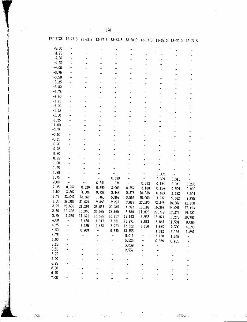
178 .. l PHI SIZE 13-27.5 13-32.5 13-37.5 13-42.5 13-50.0 13-57 .5 13-65.0 13-70.0 13-77 .5
-5.00
f -4. 75
( -4.50 -4.25
f -4.00 -3.75
f -3.50 -3.25
l -3.00 ( -2.75 '
I -2.50 -2.25 -2.00
l -1. 75
j -I.SO -1.25
' -1.00 -0. 75
l -0.50 -0.25
I 0.00
' 0.25
I 0.50 0.75
' 1.00 1.25 I.SO 0.309 1.75 0.690 0.309 0.341 ! 2.00 0.341 1.034 0.313 0.154 0.341 0.270
I 2.25 0.262 0.539 0.390 2.069 0.552 2.188 0.154 0.909 0.809 2.50 2.362 3.504 0.732 3.448 0.276 10. 938 0.463 3.182 3.504 2. 75 22.047 12.669 1.463 5.862 0.552 25.000 2. 932 5.682 8.895
I 3.00 34.383 21.024 9.268 8.276 0.829 22.500 12.346 10.682 12. 938 3.25 29.659 21.294 25.854 20.345 4.972 17.188 16.358 14. 091 27.493 I 3.50 10.236 19.946 36.585 29.655 8.840 II .875 27. 778 17. 273 19.137
l 3.75 1.050 I 1.321 16.585 16.207 I 9. 613 5. 938 18.827 17.273 10.782 4.00 5.660 7.317 7. 931 21. 271 2.813 8.642 II .591 8,086 4.25 3.235 1.463 3.793 13.812 1.250 4.630 7 .500 6.199 4.50 0,809 0.690 12.155 4.012 6,136 1.887 4. 75 8.0ll 2.160 4.545 5.00 5.525 0. 926 0.455
I 5.25 3.039 5.50 0.552
I · 5.75
6.00 6.25
I 6.50
I 6.75 7.00
'

179
PHI SIZE 13-82.5 14-2.5 14-1.5 14-12.5 18-17.5 30-2.5 30-1.5 30-12.5 30-17.5
( -5.00 -4. 75
{ -4.50 -4.25
f -4.00 -3. 75 7. 701
r -3.50 0.000 -3.25 2.640
1 -3.00 0.000 ~ -2. 75 0,000
[ -2.50 1.447 -2.25 1.616 -2.00 0.000 I -!. 75 0.626
i -I.SO 0.508 -1.25 0.305
I -1.00 0.533 -0. 75 0.626
! -0.50 0.423 -0.25 0.838
1 0.00 l .'164 0.292 ' 0.25 0.210 0.133 2.522 2.047 0.368
I 0.50 1.050 4.890 3.986 3.801 1.471 0. 75 2.311 7.090 4.832 3.801 4. 412 1.00 3.361 8.313 5.044 6. 725 11. 581 0.217 0.984 1.099 1.25 6.303 15.403 8.606 10,526 17.463 0.868 2.295 3.846 1.50 6.933 20.049 10. 713 21.345 15.441 3.688 3. 934 6.593 1. 75 7.563 18.093 17.221 28.070 11.213 II. 931 10.164 14. 835 I 2.00 7 .143 · 14.425 16.586 10.819 9. 927 34.924 21. 967 25.824
I 2.25 2.692 7.143 6.112 7.142 7 .602 7.353 27.332 27.869 25.000 2.50 4.231 8.824 3.178 2.522 l. 754 6.802 9.328 17 .377 12.363 2.75 8.077 14.286 1.222 1.26] 2.339 7.169 5.857 7.213 7.692 l 3.00 15.000 16.597 0.489 0.838 0.877 4.228 3.905 6.230 2.473 3.25 21.154 7.983 0, 919 I. 735 I. 961 0.275 j 3.50 21. 923 6,933 1.287 0. 217
I 3.75 12.692 2.311 0.368 4.00 7.308 1.050 4.25 3.462
l 4.50 2.308 4. 75 1.154 I 5.00
l 5.25 5.50 5. 75
I 6.00 6.25 6.50
I 6.75 7.00

180
J PHI SIZE 30-22.5 30-27.5 30-32.5 30-37.5 33-2.5 33-5.0 35-7.5 35-12.5
l 35-2.5
-5.00
\ -4. 75 -4.50
i -4.25
{ -4.00 -3. 75
r -3.50 2.311 -3.25 2.040
' -3.00 3.401 ( -2.75 0.572
( -2.50 0.471 -2.25 l.561 -2.00 2.125
( -l.75 l.986
' -I.SO 2.226 I -1.25 2.543 <
( -1.00 3.509 -0.75 4.575
I -0.50 5. 766 -0.25 6.098 0.00 11.693
I 0.25 12.203 ' l 0.50 .0.389 8.641 0.630 0.208 I 0.75 0.597 0.389 6.268 0.840 0.208 ! 1.00 l. 791 2.335 0 .332 4.235 2.101 0.624
1.25 6.866 7.004 0.682 1.661 l.lll 2.535 6. 723 l.247 1.50 17.313 12.840 1.364 2.326 1.481 1.523 14.286 2.079 l. 75 23.284 19.066 7.273 0.150 3.987 3. 704 2.373 17.647 3.326
! 2.00 25.672 20.233 8.864 0.150 3.987 4.014 3.045 13.655 8.316
I 2.25 H.627 20.623 10.455 0.599 7.309 JO.ODO 2.373 9.454 8.316 2.50 6.567 12.062 6,364 4. 790 9.967 12.593 2.373 7.353 9.979 2.75 2.687 3.113 3.864 H.072 12. 625 13.333 1.863 10.7H 6.861 .. •
I 3.00 0.597 1.556 4.773 25.449 13.621 15.185 l.182 9.034 7.069 • 3.25 0.389 13.864 24.252 16.6Jl 19.630 0.510 3.782 14.345 ; 3.50 15.227 20.359 1U86 ll .481 2. 941 17.879 l
I 3. 75 14.091 7.784 7 .309 4.444 0.840 8.940 4. 00 5.909 2.395 I. 993 1.111 5.198 4.25 4.318 2.326 0. 741 3.119
j 4.50 2.045 1.329 0.370 2.079 4.75 o. 909 0.332 0. 741 0.208 5.00
I 5.25 5.50 5. 75
! 6.00 6.25
I 6.50
I 6.75 7.00

181
PHI SIZE 35-17.5 35-22.5 36-2.5 36-10.0 37-2.5 38-2.5 38-7.5 38-12.5 38-17.5
-5.00 -4. 75
1 -4.50 -4.25
f -4.00 -3. 75
r -3.50 -3.25
' -3.00 ( -2.75
' -2.50 -2.25
I -2.00 -1. 75
I -1.50
' -1.25
I -1.00 -0. 75
I -0.50 -0.25 0.00
, 0.25
I 0.50 o. 75 0.310
l 1.00 1.858 1.25 0.735 0.272 0.353 4.025 1.50 1.838 O.H8 0.259 0.074 0.272 0.282 0. 707 16.099 0.888 1. 75 1.838 0.448 0. 777 0.148 0.817 1.127 2.473 34.056 0.888 2.00 2.206 0.896 2.850 0.148 2.452 4.507 5.654 18.885 0.592
I 2.25 2.206 0.896 11.658 0.185 6.812 16.620 18.375 10.217 0.592 '
'" 2.50 1.838 0.896 30.570 0.554 11.717 30. 986 31.802 6.192 0.296 j 2.75 2.574 0.896 30.311 1.476 14.169 27.606 26.148 5.573 0.296 '~
I 3.00 2.941 0.896 14.508 4.059 18.529 10.423 11.661 2.477 0.592 "' 3.25 6.250 0.896 5.181 14. 760 24.251 6.479 2.474 0.310 0.296 3.50 14.338 2.687 1.036 32. 472 13.896 1. 972 0.353 0.296 3.75 22. 794 4.179 0.259 27.306 5.450 3.550 4.00 15. 441 7.463 0.518 9.963 1.090 10. 947
! 4.25 9.926 11.343 1.036 5.535 0.272 18.047
I 4.50 8.088 11.343 0.777 2.583 16,272 4. 75 4.412 10.448 0.259 o. 738 14. 497
I 5.00 2.206 8.657 10.355
l 5.25 0.368 8.060 8.580 5.50 8.358 7. 988 5. 75 6.567 5.325
I 6.00 8.358
l 6.25 5.075 6.50 1.194
I 6.75 7.00
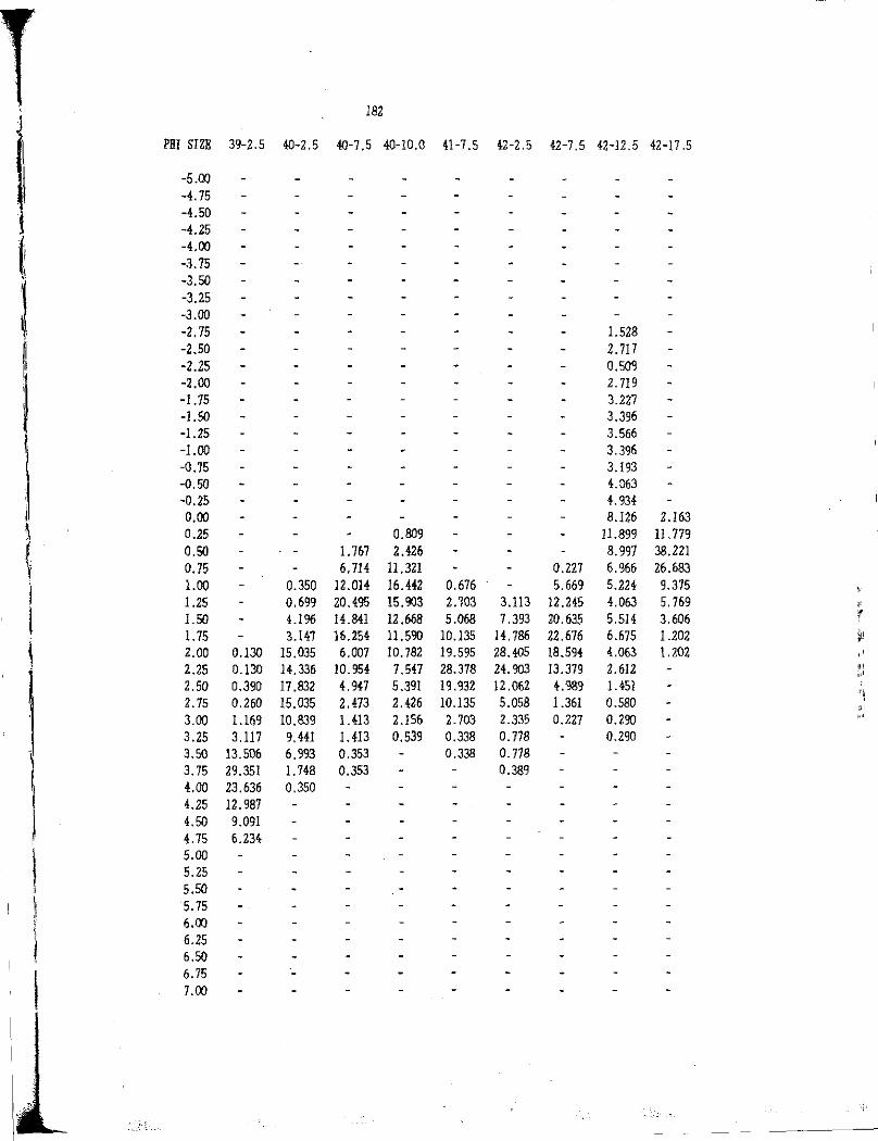
182
l PHI SIZB 39-2.5 40-2.5 40-7.5 40-10.0 41-7. 5 42-2.5 42-7.5 42-12.5 42-17.5
I -5.00 -4.75
i -4.50 -4.25
(1 -4.00 -3.75
,\ -3.50
l -3.25 -3.00 -2. 75 1.528 1
[! -2.50 2. 717 -2.25 0.509
1 -2.00 2. 719 -l.75 3.227 -l.50 3.396 -1.25 3.566
! -1.00 3.396 -0.75 3.193 -0.50 4.063 -0.25 4. 934
I 0.00 8.126 2.163 ~ 0.25 0.809 ll.899 11. 779
~ 0.50 1. 767 2.426 8.997 38.221 0.75 6,714 11. 321 0.227 6.%6 26.683 1.00 0.350 12 .014 16.442 0.676 5.669 5.224 9.375 l.25 0.699 20.495 15.903 2.703 3.113 12 .245 4.063 5. 769 ,I"
1.50 4.196 14.841 12.668 5.068 7 .393 20.635 5.514 3.606 r l. 75 3.147 16.254 11.590 10.135 14. 786 22.676 6.675 1.202 ~!
2.00 0.130 15,035 6.007 10. 782 19.595 28.405 18.594 4.063 l.202 2.25 0.130 14.336 10. 954 7.547 28.378 24. 903 13.379 2.612 ,,!
"' 2.50 0.390 17 .832 4.947 5.391 19.932 12.062 4. 'lll9 1.45] '1 2.75 0.260 15.035 2.473 2.426 10.135 5.058 1.361 0.580 11:
3.00 1.169 10.839 1.413 2.156 2.703 2.335 0.227 0.290 ,.,.,
3.25 3.117 9.441 1.413 0.539 0.338 o. 778 0.290 3.50 13.506 6.993 0.353 0.338 0. 778 3.75 29.351 l. 748 0.353 0.389 4.00 23.636 0.350 4.25 12.987 4.50 9.091
! 4. 75 6.234
\ 5.00 5.25
I 5.50
l 5.75 I 6.00
l 6.25 6.50
I 6. 75 7.00

' 183 J I PHl SIZE 42-22.5 43-2.5 43-7 .5 43-12.5 43-17.5 43-22.5 44-7 .5 44-12.5 46-2.5
I -5.00 -4. 75 -4.50 -4.25 -4.00 -3. 75 -3.50 -3.25 -3.00 -Z.75 -2.50 -2.25 -2.00 -1. 75 -1.50 -1.25 -1.00 -0. 75 -0.50 1.460 -0.25 5.5% 0.00 11.192 0.25 25.304 0.50 !8.978 l.044 0.134 0.75 14.599 2.505 0.067 1.00 8.029 · 2.923 0.134 1.25 6.326 19.833 0.134 0.460 ,.,
1.50 5.109 LOH 31. 733 0.101 1.839 ,,
1. 75 2.433 0,667 0.656 1.351 15.866 0.101 4.368 l·'.
2.00 0.487 1.000 2.188 3.041 8. 768 0.336 9.195 ,, 2.25 0.487 7.333 8.534 8.784 5.637 0.336 0.263 14.023 :J 2.50 15 .000 18.818 13.514 0.093 3.132 0.336 0.175 18.621 :;1.r
• i 2. 75 28.667 27.352 II. 486 0.093 2.296 1.007 0.131 24.368 ''1
l 3.00 26.333 26.696 13.176 0.216 I.879 2.349 2.632 !5.172 :11
3.25 12.333 10. 722 19.257 0.525 1.879 7 .383 6.433 3.908
i 3.50 3.333 3,063 15.203 3.086 1.8?9 18. 792 15.497 3.678
I 3.75 3.333 1.532 7,095 11. 420 0.626 22.819 14. 620 2. 759 4.00 1.667 0.219 2,365 16.358 16.779 12.573 1.609 4.25 0.333 0.219 2.027 15.123 10. 738 10.819 4.50 l.014 13.272 7 .383 9. 942 4.75 0.338 11.111 4.698 6.433 5.00 0.338 7. 716 2.685 4. 971 5.25 6.790 2.013 4. 971 5.50 6.113 1.678 3.801 5. 75 5.556 3.801 6.00 2.469 I. 754 6.25 0.585 6.50 6.75 7.00
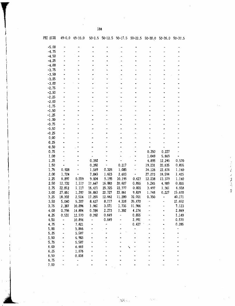
184 j
I PHI SIZE 49-0.0 49-10.0 50-2.5 50-12.5 50-17.5 50-22.5 50-30.0 50-35.0 50-37.5
l -5.00 -4. 75 -4.50
i -4.25 ' ! -<!.00
-3.75 I -3.50 ( -3.25 ' -3.00
-2. 75 -2.50 -2.25 -2.00 -1. 75 -1.50 -J.25 -1.00 -0. 75 -0.50 -0.25 0.00 0.25 0.50 0.75 0.350 0.227 1.00 1.049 5.669 1.25 0.392 4.895 12.245 0.570 1.50 0.392 0.217 19.231 20.635 0.855 1.75 0.928 1.569 0.325 1.085 24.126 22.676 1.140 2.00 I. 724 7.843 1.623 2.603 27.273 IB.594 1.425 2.25 6.897 0.559 9.804 5.195 10.195 0.427 12.238 13. 379 1.140
:'.,11
2.50 12.732 1.117 17 .647 16.883 20,607 0.855 5.245 4. 989 0.855 .,11
2.75 22.812 1.117 16.471 25.325 22. 777 0.855 3.497 1.361 4.558 1!1
3.00 27 .851 J.397 16.863 22. 727 23.861 9.829 1. 748 0.2Z7 15.670 ,,
3.25 18.302 2.514 17 .255 12.662 11.280 32 .051 0.350 40.171 3.50 5.040 5.307 8.627 8.ll7 4.338 35. 470 21. 652 3.75 2.387 10.894 1.961 3.571 I. 735 II. 966 7.123 4.00 0. 796 14.804 0. 784 2.273 l.302 4.274 2.849 4.25 0.531 12.570 0.392 0.649 0.855 1.140 4.50 10.894 0.649 2. 991 0.570 4. 75 7.821 0.427 0.285 5.00 5.866 5.25 5.587 5.50 6.983 5.75 5.587 6.00 4.469 " -6.25 1.676 6.50 0.838 6.75 7.00

185 J I PHI SIZE 51-2.5 51-7.5 51-12.5 51-17.5 52-2.5 52-7.5 52-12.5 52-17.5 53-2.5
I -5.00 ' I -4. 75
-4.50 -4.25 -4.00 -3.75 -3.50 -3.25 6.813 -3.00 0.000 -2.75 2.504 -2.50 1.868 -2.25 0.377 -2.00 1. 789 -1. 75 3.422 -1.50 2.064 -1.25 1.939 -1.00 3.085 -0. 75 2 .151 -0.50 2.543 -0.25 2.543 0.00 2. 935 0.25 0.433 0.398 0.242 0.251 4.890 0.50 . 0.866 o. 996 0.483 2.057 5.478 0.75 0.519 3.030 1.394 0. 787 1. 691 0.599 4.370 14.096 1.00 3.117 7 .359 4. 781 2.362 3,623 1.497 5.656 12.919 1.25 6.234 19.913 18.327 7.874 7. 729 4.491 6.170 9.002 0.209 1.50 11.429 22.511 32.669 22.047 15,700 10.479 8. 740 4.309 0.418 1. 75 17.662 19.481 27.092 31.496 20.290 20.958 16.195 4.309 0.835 2.00 23.377 13.853 8. 765 16.535 20.290 30.240 25.193 4.890 3.549 2.25 19.221 6.494 2. 789 7 .087 15. 942 20.659 19.280 3.328 18.372 2.50 9.351 3.030 1.594 7.874 9.662 8.084 8. 740 1.374 28.184 2.75 4.156 1.299 0.797 3.150 3.382 1.7% 2.571 o. 981 20.668 3.00 2.078 0.433 0.398 0. 787 0, 725 0.898 0. 771 0.392 14.823 3.25 1.039 0.216 0.242 0.299 8.142 3.50 0.519 0.087 3.132 3. 75 0.519 0.216 1.253 4.00 0.260 0.390 0.418 4.25 0.519 0.390 4.50 4.75 5.00 5.25 5.50 5, 75 6.00 6.25 6.50 6. 75 7.00
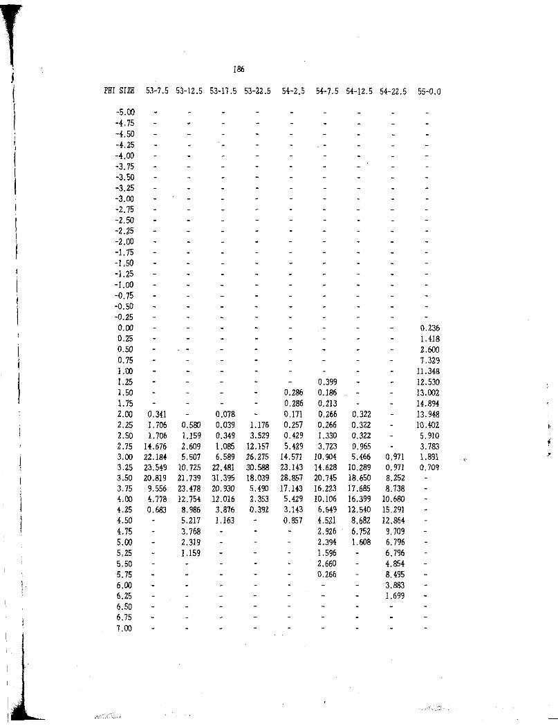
; 186
i PH! SIZE 53-7.5 53-12.5 53-11.5 53-22.5 54-2.5 54-7.5 54-12.5 54-22.5 55-0.0
I -5.00 I -4.75 -4.50 -4.25 -4.00 -3. 75 -3.50 -3.25 -3.00 -2.75 -2.50 -2.25 -2.00 -1. 75 -1.50 -1.25 -LOO -0.75 -0.50 -0.25 0.00 0.236 0.25 1.418 0.50 2.600 0. 75 7 .329 1.00 11.348 1.25 0.399 12.530 1.50 0.286 0.186 13.002 1. 75 0.286 0.213 14.894 2.00 0.341 0.078 0.l71 0.266 0.322 13.948 2.25 I. 706 0.500 0.039 1.176 0.257 0.266 0.322 10.402 I'/,
2.50 1.706 1.159 0.349 3.529 0.429 l.330 0.322 5. 910 111;1
2. 75 14.676 2.609 1.085 12.157 5.429 3.723 0.965 3. 783 1,1i
3.00 22.184 5.507 6.589 26.275 14.571 10.904 5.466 0,971 1.891 '.~'
3.25 23.549 10.725 22.481 30.588 23.143 14.628 10.289 o. 971 0. 709 3.50 20.819 21. 739 31.395 18.039 28.857 20. 745 18.650 8.252 3. 75 9.556 23.478 20.930 5.490 17.143 16.223 17 .685 8.738 4.00 4. 718 12.754 12.016 2.353 5.429 10. 106 16.399 10.680 4.25 0.683 8.986 3.876 0.392 3.143 6.649 12.540 15.291 4.50 5.217 1.163 0.857 4.521 8.682 12.864 4. 75 3. 768 2. 926 6. 752 9. 709 5.00 2.319 2.394 1.608 6.796 5.25 1.159 1.596 6. 796 5.50 2.660 4.854 5. 75 0.266 8.495 6.00 3.883 6.25 1.699 6.50 6. 75 7 .00

' 187
' I PHI SIZE 55-10.0 55-15.0 55-20.0 55-25.0 55-30.0 55-35.0 56-2.5 56-12.5 56-17.5
I -5.00 ' I -4. 75 -4.50 -4.25 -4.00 -3.75 -3.50 -3.25 -3.00 -2. 75 -2.50 -2.25 -2.00 -l. 75 -I.SO -1.25 -1.00 -0. 75 -0.50 -0.25 0.00 0.25 0.216 0.50 2.808 -0.75 9.935 0.253 1.064 1.00 22.030 1.972 2.353 2.020 4.059 2.837 1.25 22.246 10.986 10.882 9.091 9.225 3.546 1.50 20.518 29.577 25.882 24.495 21. 771 3. 901 I. 75 12.959 37.465 27.941 30.303 29.520 10.284 2.00 5.616 15.21] 18.824 18.687 18.450 17 .376 0.072 2 .25 1.080 3.380 9.118 7 .576 9.594 28. 723 0.506 0.143 2.50 1.080 1.408 4.118 4.545 4.428 22.340 0.253 0.143 0.239 'ii/I
2.75 1.080 0.882 l.010 1.845 7.092 0.253 0.251 0.239 {
3.00 0.432 0.758 o. 738 2.128 0.253 0.824 0. 716 '.''i:
3.25 o. 758 0.369 0. 709 1.266 1.434 3.341 3.50 0.505 5.316 I. 792 9.308 3. 75 10.886 13.620 14.320 4.00 12.405 18.638 18.377 4.25 13.924 15.412 17.422 4.50 11.139 11 .111 12 .411 4.75 8.101 10.394 10.740 5.00 7.089 6.093 6.683 5.25 6.582 4.301 5.012 5.50 6.076 4.659 l.l93 5.75 5.316 5.735 6.00 3. 797 3.943 6.25 4.051 1.434 6.50 2.025 6. 75 0. 759 1.00
i 1 l l I
,l__

I 188 I i PHI SIZE 56-22.5 56-27.5 56-32.5 56-37.5 57-2.5 57-7.5 57-12.5 57-17 .5 57-22.5
! -5.00 -4.75 -4.50 -4.25 -4.00 -3. 75 -3.50 -3.25 -3.00 -2. 75 -2.50 -2.25 -2.00 -l.75 -1.50 -1.25 -l.00 -0. 75 -0.50 -0.25 0.00 0.25 0.50 0.75 1.00 1.25 1.50 0.146 0.100 1. 75 0.226 0.146 0.100 1.105 2.00 0.226 0.583 0.880 0. 974 0.798 2.210 2.25 2. 715 4.082 1.173 0.649 9.182 0.179 12.983 2.50 16.290 16,327 3.519 0.325 0.295 27.745 0.179 0.108 32.873 2.75 32.127 28.863 7 .918 2.597 0.295 32 .136 3. 750 0.043 30.111 3.00 28.507 24.490 20.821 6.169 0.590 15.%8 9.821 0.065 14.088 3.25 12.670 15.743 27.859 8.442 0.885 6.387 15.179 0.324 4.420 3.50 4. 977 6.414 33.138 15.260 2.655 4.192 18. 929 0.540 1.657 3. 75 1.810 2.041 4.399 15.909 7 .375 2.395 16.786 3.024 0.552 4.00 0.452 0.583 0.293 12.013 11. 799 o. 798 10.536 8.423 4.25 0.583 9.091 11. 799 0.200 6.250 11. 231 4.50 8.117 10.619 5.536 12.095 4. 75 5.519 9. 735 4.286 12. 311 5.00 4.870 7. 965 4.107 9.071 5.25 3.896 7 .965 4.464 9.503 5.50 3,571 9.145 8.639 5.75 1.948 7 .670 8.855 6.00 0.649 6.195 7 .127 6.25 4.425 7.127 6.50 0.590 1.512 6.15 7.00

4 189 ' I PHJ SIZE 57-27.5 57-32.5 57-37.5 57-50.0 57-57 .5 58-2.5 58-7 .5 58-12.5 58-15.0
I -5.00
I -4.75 -4.50 -4.25 -4.00 -3.75 -3.50 -3.25 -3.00 -2. 75 -2.50 -2.25 -2.00 -1. 75 -1.50 -1.25 -LOO -0. 75 -0.50 -0.25 0.00 0.25 0.541 0.50 l.903 1.892 0.75 0.126 4.228 2.162 1.00 0.631 8.034 5.946 2. 703 1.25 0.304 1.515 9.302 10.000 7.862 1.50 0.608 0.505 1.429 0.680 6.566 10.359 19.730 14.251 1.15 4.559 0.505 l. 905 0.454 11. lll 13.531 17.027 28.501 2. 00 J0.334 13.131 7 .381 1.361 0.167 l 7. 424 15.645 15.676 21.130 2.25 20.365 30.303 II. 905 3.401 0.333 22.222 12.051 12.432 13.514 2.50 28.875 33.333 19.524 4.535 0.333 23.232 8.457 7.027 8.108 2.75 17.933 15.152 19.762 6.122 0.500 11.364 9,091 3. 784 3.686 3.00 6. 991 5.556 17.619 9.751 0.667 4.545 4.440 2.432 0.246 3.25 6.687 1.010 12.857 15.873 2.667 1.263 2.537 1.08] 3.50 2.128 0.505 4.286 20,408 6.333 0.423 0.270 3. 75 1.216 2.381 13,379 JO .333 4.00 0.476 7.029 15.000 4.25 0.476 7 .029 16.667 4.50 4.535 15.000 4.75 2.948 10.667 5.00 . 2.494 7.333 5.25 7.333 5.50 6.667 5. 75 6.00 6.25 6.50 6.75 7.00

l l l
I ,
1..L_ I
PHI SIZE 58-20.0
-5.00 -4. 15 -4.50 -4.25 -4.00 -3. 75 -3.50 -3.25 -3.00 -2.75 -2.50 -2.25 -2.00 -J.75 -1.50 -J.25 -LOO -0.75 -0.50 -0.25 o.oo 0.25 a.so 0.75 1.00 0.241 1.25 1.205 !.SO 5.301 1.75 28.193 2.00 40.723 2.25 11.566 2.50 2.169 2.75 5. 783 3.00 4.096 3.25 0,723 3.50 3.15 <!.00 4.25 4.50 4.75 5.00 5.25 5.50 5.75 6.00 6.25 6.50 6.75 7.00
190
58-27.5 58-30.0 58-35.0
8.873 0.000 0.396 2.518 3.253 2. 150 3.303 2.m 2.267
0.955 2.480 0.707 2.072 0.334 1. 991 0.258 1. 978 0.822 1.570 0.516 1.344 0.869 0.973 1.366 0.973 2.341 1.149 2.933 1.608 7.233 2. 983 9.775 5. 739
H.065 5.739 11. 915 5.972
0.988 JO. 940 7. 9]8 0.593 8. 991 9.645 I. 779 6.Ml 8.264 I. 779 8.399 4.823 1.779 3.908 2.757 0. 791 3.908 l. 721 1.186 1.366 1.608 3.755 0.975 0.691 ,,
18.577 0.583 0.232 ,,
32 .016 22.127 8.696 2. 767 1. 779 0.791

,l
APPENDIX D
( In pocket)
Surface Geology of the Souris River Map Area, North Dakota. this map may be obtained through the North Dakota Geological University Station, Grand Forks, North Dakota, 58202-8156.
,·-.:.:::•
Copies of Survey,
..

,i •.
REFERENCES CITED
Aggregate Resources Section, 1980, Quaternary geology map: southern Manitoba; Virden 62F: Mineral Resources Division, Geological Map AR80-6, scale 1:250,000.
Albertson, M. L., Dai, Y. 8., Jensen, R. A., and Rouse, Hunter, 1950, Diffusion of submerged jets: American Society of Civil Engineers Transactions, v. 115, p. 629-697.
Allen, J. R. L., 1968, The diffusion of grains in the lee of ripples, dunes, and sand deltas: Journal of Sedimentary Petrology, v. 38, p. 621-633.
Ashley, G. M., 1975, Rhythmic sedimentation in Glacial Lake Hitchcock, Massachusetts--Connecticut, in Jopling, A. V., and McDonald, B. C., eds.,- Glaciofluvial and gTaciolacustrine sedimentation: Society of Economic Paleontologists and Mineralogists Special Publication 23, p. 304-320.
Axelsson, Valter, 1967, The Laitaure delta. A study of deltaic morphology and processes: Geografiska Annaler, v. 49A, p. 1-127.
Bagnold, R. A., 1954, Experiments on a gravity-free dispersion of large solid spheres in a Newtonian fluid under shear: Royal Society of London, Proceedings, Series A, v. 225, p. 49-63.
Baker, V. R., 1973, Paleohydrology and sedimentology of Lake Missoula flooding in eastern Washington: Geological Society of America Special Paper 144, 79 p.
Baker, V. R., and Kochel, R. C., 1979, Martian channel morphology: Maja and Kasei Valles: Journal of Geophysical Research, v. 84, p. 7961-7983.
Bates, C. C., 1953, Rational theory of delta formation: American Association of Petroleum Geologists Bulletin, v. 37, p. 110-113.
Beecroft, Ian, 1983, Sediment transport during an outburst from glacier de Tsidjiore Nouve, Switzerland: Journal of Glaciology, v. 29, p. 185-190.
192

' j 193
61uemle, J.P., 1982, Geology of McHenry County, North Dakota: North Dakota Geological Survey Bulletin 74, Part I, and North Dakota State Water Commission County Groundwater Studies 33, Part I, 49 p.
Bluemle, J.P., 1985, Geology of Bottineau County, North Dakota: North Dakota Geological Survey Bulletin 78, Part I, and North Dakota State Water Commission County Groundwater Studies 35, Part I, 57 p.
Bluemle, J. P., 1988, Verbal communication: Grand Forks, North Dakota, North Dakota Geological Survey.
Bretz, J H., 1929, Valley deposits east of the Channeled Scabland: Journal of Geology, v. 37, p. 393-427.
Brophy, J. A., and B1uem1e, J.P., 1983, The Sheyenne River: its geological history and effects on Lake Agassiz, in Teller, J. T., and Clayton, Lee, eds., Glacial Lake Agassiz: Geological Association of Canada Special Paper 26, p. 173-186.
Carlson, C. G., and Freers, T. F., 1975, Geology of Benson and Pierce Counties, North Dakota: North Dakota Geological Survey Bulletin 59, Part I, and North Dakota State Water Commission County Groundwater Studies 18, Part I, 32 p.
Chee!, R. J., and Rust, B. R., 1980, Coarse grained facies of glaciomarine deposits near Ottawa, Canada, in Davidson-Arnott, R., Nickling, W., and Fahey, B. D., eds.,l(esearch in glacial, glacio-fluvial, and g1acio-lacustrine systems: Guelph Symposium on Geomorphology, 6th, 1980, Proceedings, p. 279-295.
Christiansen, E. A., 1956, Glacial geology of the Moose Mountain area, Saskatchewan: Saskatchewan Department of Mineral Resources Report 21, 35 p.
Church, Michael, and Gilbert, Robert, 1975, Proglacial fluvial and lacustrine environments, in Jopling, A. V., and McDonald, B. C., eds., Glaciofluvial and gTaciolacustrine sedimentation: Society of Economic Paleontologists and Mineralogists Special Publication 23, p. 22-100.
Clayton, Lee, 1980, Geologic Map of North Dakota: U.S. Geological Survey, scale 1:500,000.
Clayton, Lee, 1983, Chronology of Lake Agassiz drainage to Lake Superior, in Teller, J. T., and Clayton, Lee, eds., Glacial Lake Agassiz: Geological Association of Canada Special Paper 26, p. 291-307.
•. ::.....=aai.

I ',
I '
I
I
I .
1.L
194
Clayton, Lee, and Moran, S. R., 1982, Chronology of late Wisconsinan glaciation in middle North America: Quaternary Science Reviews, v. l, p. 55-82.
Clayton, Lee, Moran, S. R., Bluemle, J. P., 1980, Explanatory text to accompany the Geologic Map of North Dakota: North Dakota Geological Survey Report of Investigation 69, 93 p.
Deal, D. E., 1971, Geology of Rolette County, North Dakota: North Dakota Geological Survey Bulletin 58, 89 p.
Elson, J. A., 1955, Surficial geology of the Tiger Hills region, Manitoba [Ph.D. Dissertation]: New Haven, Connecticut, Yale University, 316 p.
Emiliani, Cesare, Rooth, Claes, and Stipp, J. J., 1978, The late Wisconsin flood into the Gulf of Mexico: Earth and Planetary Science Letters, v. 41, p. 159-162.
Erickson, Kirth, 1967, Hydrology of the Charlotte Lobe Delta: North Dakota Academy of Science, Proceedings, v. 21, p. 9-16.
Eyles, Nicholas, Clark, C. M., and Clague, J. J., 1987, Coarse-grained sediment gravity flow facies in a large supraglacial lake: Sedimentology, v. 34, p. 193-216.
Eyles, C. H., 1987, Glacially influenced submarine-channel sedimentation in the Yakataga Formation, Middleton Island, Alaska: Journal of Sedimentary Petrology, v. 57, p. 1004-1017.
Fahnestock, R. K., 1963, Morphology and hydrology of a glacial stream: White River, Mount Rainier, Washington: U.S. Geological Survey Professional Paper 422-A, 70 p.
Feeley, M. H., Buffer, R. T., and Bryant, W.R., 1985, Deposition units and growth pattern of the Mississippi Fan, in Bouma, A.H., Normark, W.R., and Barnes, N. E., Submarine fans~nd related turbidite systems, New York, New York, Springer-Verlag, p. 253-257.
Fenton, M. M., Moran, S. R., Teller, J. T., and Clayton, Lee, 1983, Quaternary stratigraphy and history in the southern part of the Lake Agassiz Basin, in Teller, J. T., and Clayton, Lee, eds., Glacial Lake Agassiz=- Geological Association of Canada Special Paper 26, p. 49-74.
Folk, R. L., 1980, Petrology of sedimentary rocks: Austin, Texas, Hemp i 11 Publishing Co. , 185 p.
Gibbs, R. J., 1974, A settling tube system for sand-size analysis: Journal of Sedimentary Petrology, v. 44, p. 583-588.
195
Gilbert, Robert, 1973, Processes of underflow and sediment transport in a British Columbia mountain lake: National Research Council of Canada, Associate Committee on Geodesy and Geophysics, Subcommittee on Hydrology, Symposium no. 9, p. 492-507.
Gilbert, Robert, 1975, Sedimentation in Lillooet Lake, British Columbia: Canadian Journal of Earth Sciences, v. 12, p. 1697-1711.
Griggs, G. B., Kulm, L. D., Waters, A. C., and Fowler, G. A., 1970, Deep-sea gravel from Cascadia Channel: Journal of Geology, v. 78, p. 611-619.
Gustavson, T. C., Ashley, G. M., and Boothroyd, J. C., 1975, Depositional sequences in glaciolacustrine deltas, in Jopling, A. V., and McDonald, B. C., eds., Glaciofluvial and glaciolacustrine sedimentation: Society of Economic Paleontologists and Mineralogists Special Publication 23, p. 264-280.
Hampton, M.A., 1975, Competence of fine-grained debris flows: Journal of Sedimentary Petrology, v. 45, p. 834-844.
Hein, F. J., 1982, Depositional mechanisms of sediments, Cap Enrage Formation, Quebec:
deep-sea coarse elastic Canadian Journal of
Earth Science, v. 19, p. 267-287.
Hein, F. J., 1984, Deep-sea and fluvial braided channel conglomerates: a comparison of two case studies, in Koster, E. H., and Steel, R. J., eds., Sedimentology of gravels"a:nd conglomerates: Canadian Society of Petroleum Geologists, Memoir 10, p. 33-49.
Hiscott, R. N., and Middleton, G. V., 1979, Depositional mechanics of thick-bedded sandstones at the base of a submarine slope, Tourelle Formation (lower Ordovician), Quebec, Canada, in Doyle, L. J., and Pilkey, 0. H., Geology of continental slopes~: Society of Economic Paleontologists and Mineralogists Special Publication no. 27, p. 307-326.
Hjulstrom, Filip, 1952, The geomorphology of the alluvial outwash plains (sandurs) of Iceland, and the mechanics of braided rivers: International Geographical Union, 17th Congress, Proceedings, Washington, p. 337-342.
Houboult, J. J. H. C., and Jonker, J. B. M., 1968, Recent the eastern part of the Lake of Geneva (Lac Leman): Mijnbouw, v. 47, p. 131-148.
sediments in Geologie en
Karrow, P. F., and Calkin, P. E., eds., 1985, Quaternary evolution of the Great Lakes: Geological Association of Canada Special Paper 30, 258 p.

, '
\ '
196
Kehew, A. K., 1982, Catastrophic flood hypothesis for the or1g1n of the Souris spillway, Saskatchewan and North Dakota: Geological Society of America Bulletin, v. 93, p. 1051-1058.
' Kehew, A. K., and Clayton, Lee, 1983, Late Wisconsinan catastrophic
floods and development of the Souris--Pembina spillway system, in Teller, J. T., and Clayton, Lee, eds., Glacial Lake Agassiz: Geological Association of Canada Special Paper 26, p. 187-209.
Kehew, A. K., and Lord, M. L., 1986, Origin and large-scale erosional features of glacial-lake spillways in the northern Great Plains: Geological Society of America Bulletin, v. 97,162-177.
Kehew, A. K., and Lord, M. L., 1987, Glacial-lake outbursts along the mid-continent margins of the Laurentide Ice-sheet, in Mayer, L., and Nash, D., eds., Catastrophic flooding: Binghamton Symposia in Geomorphology: International Series, no. 18: Boston, Allen and Unwin, Inc., p. 95-120.
Kehew, A. K., Lord, M. L., and Lowrie, Allen, 1986, Tracing catastrophic glacial-lake outbursts from the southern margin of the Laurentide Ice Sheet to deposition along the Louisiana offshore: Geological Society of America Abstracts with Programs, v. 18, p. 653.
Kenyon, P. M., and Turcotte, D. L., 1985, Morphology of a delta prograding by bulk sediment transport: Geological Society of America Bulletin, v. 96, p. 1457-1465.
Komar, P. D., 1985, The hydraulic interpretation of turbidites from their grain sizes and sedimentary structures: Sedimentology, v. 32, p. 395-407.
Komar, P. 0., in press, a, Discussion: Sedimentology and paleohydrology of glacial-lake outburst deposits in southeastern Saskatchewan and North Dakota (Lord and Kehew, 1987): Geological Society of America Bulletin.
Komar, P. D., in press, b, Flow-competence evaluations of the hydraulic parameters of floods: an assessment of the technique, in Beven, K. and Carling, P., eds., Proceedings of Floods 'workshop: British Geomorphological Research Group, London, John Wiley and Sons.
Lawson, D. E., 1982, Mobilization, movement and deposition subaerial sediment flows, Matanuska Glacier, Alaska; Geology, v. 90, p. 279-300.
of active Jou ma 1 of
\ 197
Leckie, D. A., and McCann, S. 8., 1980, Glacio-lacustrine sedimentation on low slope prograding delta, in Davidson-Arnott, R., Nickling, vi., and Fahey, B. D., eds., Research in glacial, glacio-fluvial, and glacio-lacustrine systems: Guelph Sympotium on Geomorphology, 6th, 1980, Proceedings, p. 261-278.
Lefever, R. D., 1986a, Texture (Unpublished computer program]: Gra~d Forks, North Dakota, University of North Dakota.
Lefever, R. D., 1986b, Contour [Unpublished computer program]: Grand Forks, North Dakota, University of North Dakota.
Lefever, R. D., 1986c, Trend [Unpublished computer program]: Grand Forks, North Dakota, University of North Dakota.
Lemke, R. vi., 1951, Glacial Lake Souris, North Dakota [Abstract]: Geological Society of America Bulletin, v. 62, p. 1459-1450.
Lemke, R. vi., 1960, Geology of the Souris River area, North Dakota: U. S. Geological Survey Professional Paper 325, 138 p.
Leventer, Amy, Douglas, F. vi., Kennet, J. P., 1982, Dynamics of the Laurentide ice sheet during the last deglaciation: evidence from the Gulf of Mexico: Earth and Planetary Science Letters, v. 59, p. 11-17.
Liverman, D. G. E., 1987, Sedimentation in ice-dammed Hazard Lake, Yukon: Canadian Journal of Earth Sciences, v. 24, p. 1797-1806.
Lord, M. L., 1987, Glacial Lake Souris--the history and sedimentology of a glacial lake inundated by catastrophic flooding: Geological Society of America Abstracts with Programs, v. 19, p. 749.
Lord, M. L., 1988, Surface Geology of the Souris River Map Area, North Dakota: North Dakota Geological Survey Atlas Series, Map 4, Sheet 1, scale 1:250,000.
Lord, M. L., and Kehew, A. E., 1987, Sedimentology and paleohydrology of glacial-lake deposits in southeastern Saskatchewan and northwestern North Dakota: Geological Society of America Bulletin, v. 99, p. 663-673.
Lowe, O. R., 1979, Sediment gravity flows: their classification and some problems of application to natural flows and deposits, in Doyle, L. J., and Pilkey, 0. H., Geology of continental slopes: Society of Economic Paleontologists and Mineralogists Special Publication no. 27, p. 75-82.
Lowe, D.R., 1982, Sediment gravity flows: II. Depositional models with special reference to the deposits of high-density turbidity currents: Journal of Sedimentary Petrology, v. 52, p. 279-297.

, ' !
I •
,-L.._ I
196
Malde, H. E., 1968, The catastrophic late Pleistocene Bonneville flood in the Snake River Plain, Idaho: U.S. Geological Survey Professional Paper 596, 52 p.
Marcus, M. G., 1960, Periodic drainage of glacier-dammed Tulsequah Lake, British Columbia: Geographical Review, v. 50, p. 89-106.
Miall, A. 0., 1977, A review of the braided-river depositional environment: Earth-Science Reviews, v. 13, p. 1-62.
Middleton, G. V., 1976, Hydraulic interpretation of sand size distributions: Journal of Geology, v. 84, p, 405-426.
Middleton, G. V., and Hampton, M.A., 1976, Subaqueous sediment transport and deposition by sediment gravity flows, in Stanley, D. J., and Swift, D. J.P., eds., Marine sediment transport and environmental management: New York, John Wiley and Sons, p. 197-218.
Middleton, G. V., and Southard, J, 8., 1964, Mechanics of sediment movement (2nd edition): Society of Economic Paleontologists and Mineralogists Short Course no. 3, 401 p.
Moran, S. R., and Deal, D. E., 1970, Glacial Lake Souris--a study in the complexity of a glacial-lacustrine environment: Geological Society of America Abstracts with Programs, v. 2, p. 398.
Nelson, C.H., 1984, Turbidity-current observations and experimental studies, in Nelson, C.H., and Nelson, T. H., Modern and ancient deep-sea fan sedimentation: Society of Economic Paleontologists and Mineralogists Special Publication Short Course no. 14, p. 16-37.
Postma, George, Thomas, B. R., and Ruegg, G. H.J., 1983, Sandygravelly mass-flow deposits in an ice-marginal lake (Saal Ian, Leuvenumschu Beek Valley, Veluwe, The Netherlands), with emphasis on plug-flow deposits: Sedimentary Geology_, v. 34, p. 59-82.
Randich, P. G., 1971, Ground-water basic data, Benson and Pierce Counties, North Dakota: North Dakota Geological Survey Bulletin 59, Part II, and North Dakota State Water Commission County Groundwater Studies 18, Part !I, 360 p.
Randich, P. G., 1981, Ground-water data for McHenry County, North Dakota: North Dakota Geological Survey Bulletin 74, Part II, and North Dakota State Water Commission County Groundwater Studies 33, Part II, 446 p.
Remple, G. A., 1987, Tills underlying the sediments of Glacial Lake Souris, north-central North Dakota [Senior Thesis]: Grand Forks, North Dakota, University of North Dakota, 34 p.

' 199
Rust, 8. R., 1977, Mass flow deposits in a Quaternary succession near Ottawa, Canada: diagnostic criteria for subaqueous outwash: Canadian Journal of Earth Sciences, v. 14, p. 1~5-184.
Schnacke, A. W., 1982, Glacial geology and stratigraphy of southeastern Pierce and southwestern Benson Counties, North Dakota (M.S. Thesis): Grand Forks, North Dakota, University of North Dakota, 140 p.
Shanmugam, G., and Moiola, R. J., 1988, Submarine fans: characteristics, models, classification, and reservoir potential: Earth-Science Reviews, v. 24, p. 383-428.
Shaw, John, 1975, Sedimentary successions in Pleistocene ice-marginal lakes, in Jopling, A. V., and McDonald, 8. C., eds., GlaciofTuvial and glaciolacustrine sedimentation: Society of Economic Paleontologists and Mineralogists Specia·, Publication 23, p. 281-303.
Shaw, John, Gilbert, Robert, and Archer, J. J. J., 1978, Proglacial lacustrine sedimentation during winter: Arctic and Alpine Research, v. 10, p. 689-699.
Smith, N. 0., 1978, Sedimentation processes and patterns in a glacierfed lake with low sediment input: Canadian Journal of Earth Sciences, v. 15, p. 471-756.
Smith, N. D., and Ashley, G. M., 1985, Proglacial lacustrine environment: physical process, in Ashley, G. M., Shaw, John, Smith, N. D., eds., Glacial sedimentary environments: Society of Economic Paleontologists and Mineralogists Short Course no. 16, p. 135-215.
Stauffer, P.H., 1967, Grain-flow deposits and their implications, Santa Ynez Mountains, California: Journal of Sedimentary Petrology, v. 37, p. 487-508.
Teller, J. T., 1985, Glacial Lake Agassiz and its influence on the Great Lakes, in Karrow, P. F., and Calkin, P. E., eds., Quaternary evoTution of the Great Lakes: Geological Association of Canada Special Paper 30, p. 1-16.
Teller, J. T., and Clayton, Lee, eds., 1983, Glacial Lake Agassiz: Geological Association of Canada Special Paper 26, 451 p.
Teller, J. T., and Thorleifson, L. H., 1983, The Lake Agassiz--Lake Superior connection, in Teller, J. T., and Clayton, Lee, eds., Glacial Lake Agassiz:-Geological Association of Canada Special Paper 26, p. 261-290.
Upham, Warren, 1896, The Glacial Lake Agassiz: U.S. Geological Survey Monograph 25, 658 p.
' ·' '
200
Williams, P. F., and Rust, B. R., 1969, The sedimentology of a braided river: Journal of Sedimentary Petrology, v. 39, p. 649-679.
Wright, L. D., 1977, Sediment transport and deposition at river mouths: a synthesis: Geological Society of America Bulletin, v. 88, p. 857-868.

10i 0 00 '
NORTH DAKOTA GEOLOGICAL SURVEY Sidney B . Anderson, Acting State Geologist AS-4-Al
45 ' R. 76 W.
5 0 5 10 MILES ==================== 5 0 5 10 KILOMETERS
MAP SCALE I : 250,000 LEGEND
POPULATED PLACES o ~ I ROADS
151
--- , R_T2 W_ IOC'OO' ' - --_ -- ;z_ 49°00
~ cO
45'
30 '
15 '
48°00'
MAP DRAFTED BY Ken L _ Dorsher
CONTOUR INTERVAL 100 FEET WITH SUPPLEMENTARY CONTOURS AT 50-FOOT INTERVALS
------ FARGO Primory,al[-weother, hord surfoc•----- ·-----25,000 to 100,000 Secondory,oH-weother,hord surface _____ _ _ _ __ _ SECTIONIZED TOWNSHIP NORTH ,-- DAKOTA
5,000 to 25,00Q-___ ____ ____ JamesRtowbn Li1:1ht-duty,011-weather , hord or improved __ = ---1,000 to 5,000 ug y Less than 1,000 Towner Fair or dry weother,unimproved --==- __ _ RAILROADS Douple Troll -------
Sini;iletrock or Multiple Interchange ______________ ·--<:J---Standord gou11e-~
BOUNDARIES International _____ -- - - --
State -------County _ _ _ _____ -- _ --
Pork or reeervatlon __ _
Londplone airpart _____ _ tt) Landing area T
Route markers: Interstate, U.S., State ___ {5) @) (@ Landmork=School,Church,Other ______ l I•
Mine 1tl
Spot e levotion in feet-------,==;;cc-~2c,2c,;5 Marsh or swamp __________ I "' .,,..".' ~ ~I Intermittent or dry stream ______ ................ ...- ... , Power line ____________ -····--- .•••.••.
BASE MAP SUPPLIED BY U.S. GEOLOGICAL SURVEY, DENV ER ,COLORADO 80225
:,: >-"' 0 2
UJ ::,
"' >-
13°
f 0:
~ 0 ;: <u a
:l APPROXIMATE MEAN DECLINATION, 1987
6
7
18
19
30
31
f'·r ~&f Lt_
\ I
5 4 3 2 I
8 9 10 II 12
17 16 15 14 13
20 21 22 23 24
29 28 27 26 25
32 33 34 35 36
ATLAS SERIES MAP AREAS
ATLAS SERIES MAP 4 SHEET Al AS-4-Al
SURFACE GEOLOGY OF THE SOURIS RIVER MAP AREA, NORTH DAKOTA
by Mark L. Lord 1988
MAP EXPLANATION
This map shows four elements of the geology of the Souris River Map Area: the lithology, topography, origin, and age of the surface sediment. Sediment characteristics are emphasized on this map; different lithologies are shown on the map by the use of color (Fig. 1). All Quaternary sedimunt of the same lithology is represented by map units of the same basic color. For example, two basic colors, orange and green, are used for ten different map units, but represent only two lithologies (sand and gravel; gravelly sand, silt, and clay). Because there are eight green map units of similar lithology, three different shades of green have been used to simplify use of the map.
The age and the origin of the sediment are shown with map~unit numbers. For example, a yellow map unit (sand) is interpreted to be either lake, river, or windblown sediment of a certain age. The specific interpretation is indicated by a map-unit number. Figure 2 shows the correlation diagram relating sediment age, origin, and lithology with map-unit number.
Detailed descriptions of the map units and line symbols used on this map are given in Figure 3. These descriptions include comments on the range of lithologic characteristics, possible origins, and mapping confidence of different map units .
In addition to the detailed map of the Souris River Map Area (left), three smaller, general maps are included on this sheet to aid the user in understanding the surface geology of the region. These three maps are 1) major landform areas (Fig. 4), 2) regional glacial margins (Fig. 5), and 3) regional glacial lakes and spillways (Fig. 6). The Souris River Map Area is divided into three landform areas, indicated by letters, based on the occurrence of simdar or genetically related landforms (Fig. 4). During the last major glacial advance, ice covered the entire
0 I
map area (Fig. 5; A). As the glacier thinned, it split into two lobes around the Turtle Mountains (Fig. 5; B); the ice remaining in the Turtle Mountains stagnated (Fig. 4; B). The Souris ice Jobe flowed around the west side of the Turtle Mountains, forming some proglacial stream deposits to the north (Fig. 4; Ca) and molding topography to the south (Fig_ 4; Cb)_ Glacial Lake Souris (Fig, 4; A) formed as meltwater ponded during the retreat of the Souris ice lobe. Sedimentladen water entered Lake Souris at the Souris River and deposited a coarse-grained delta (Fig. 4; Ac). Final drainage of Lake Souris occurred to the north (Fig. 4; Ae) into glacial Lake Hind in Manitoba (Fig. 6). During the Holocene Epoch, wind has reworked much of the sediment in Lake Souris (Fig. 4; Ad). Today, with the exception of occasional wind blowouts, sediment is reworked primarily by rivers (Fig. 4; Af, Cd).
The map of the surface geology is the result of an interpretation of the geology based on aerial photographs, field studies, and a compilation of previous work. The aerial photographs used were taken between 1951 and 1953 by the Army Map Service and printed at a scale of 1 :63,400 (1 inch:: 1 mile). Field studies were conducted during the summers of 1985, 1986, and 1987. Drilling data from about 600 holes, primarily from the North Dakota Geo logical Survey and the North Dakota State Water Commission, were used to assist this study.
This map has greatly benefited from many discussions with Ken Harris, who constructed the first map of the Atlas Series, and from a critical review by Lee Clayton. Review and comments by John Bluemle and Alan Kehew have also improved this map.
SEDIMENT ORIGIN GLACIAL LAKE SEDIMENT WINDBLOWN SEDIMENT
~ !l 0
~ ~ UNOISTLIRBED
SEDIMENT
DIST URBE D UND ISTURBED DISTURB FLAT TC DUNES BEDROCK
- Silt and clay with organic debris
-Sand, silt, and clay with organic debris
-Silt and clay
-Sand and silt
-Sand
-Sand and gravel
-Clayey, silty, sandy gravel
}-'"'""' ""'' ''"' ""' "'" "'"' -Scattered boulders over sand
-Cretaceous and Paleocene bedrock
IJJ <!) <( " <
>
~ I-
0 z z
I IJJ :ii: 0 ~ 10
IJJ en
a w <
a w
g 0
3 g
~
> <
! e < 0 0
I \
z 0 0 e ,
0
-' ;
THIN THICK OYER
GRAVf
I 0
e < ~ ~
< 0
I "' ~ fJ ..;,~1 \ I
I , , V ' ,\, ~ '
I
' 6 8 ~" <0 zO w< oO
8
s:~E :~ARRE :::C: L~~~G R~~fEr ~~~~E-F
3 A " I ,/ ., I"
. 'v -
4 .·5·
r '\ A A " r " ......... I \ I ' \ I \ I I I '
, \. V -v V V V V
I 10 16 17 18
,.., ,-. " !, Ii / \ \ ,s .. j I I I
i V ~
~ " -~w PALEOGENE
~~ ~ ct~ 65
~ CONFIDENT TIME BOUNDARY C 0
cm ~ CRETACEOUS ~ ,,--, .... -- UNCERTAI N TIME BOUNDARY ~ a
Figure 1. Sediment texture key.
>
Figure 2. Correlation diagram relating sediment age, sediment origin, lithology, and map-unit number.
DESCBIPTION OF THE MAP UNITS
QUATERNARY
9AHE FORMATION
OVERBANK SEDIMENT: Clay, silt, sand, and disseminated o rga nic debris; obscurely bedded; dark colored; commonly associated with sand and gravel of older, river-channel sediment. Where the sediment of this map un it occurs in alluvial fans, it commonly consists of poorly sorted to well sorted sand and gravel depos its.
SLOUGH AND POND SEDIMENT: Clay, silt, and disseminated organic debris; obscurely bedded; dark colored; generally less than 3 metres (10 feet) thick.
WINDBLOWN SEDIMENT
FLAT TO UNDULATING: Silt and sand, fine to medium grained; moderate ly to well sorted; obscurely bedded; surface commonly scoured and gradational to unit 4. Sediment is interpreted to be reworked sediment of unit 17
LOW-RELIEF DUNES: Sand, fine to medium grained, well sorted; obscurely bedded; dunes are as high as 6 metres (20 feet) and generally stabiliied by vegetation, but common ly have active blowouts.
HIGH- RELIEF DUNES: Same as unit 4, but dunes a1·e commonly higher (up to 20 metres; 65 feet) and have the form of longitudinal dunes where indicated on the map by thin black ];nes.
COLEHARBOR GROUP
GLACIAL SEDIMENT
~LACIAL SEDIMENT: Gravelly sand, silt, and clay; unsorted, unbedded; contain s some cobbles and boulders; as thick as 200 metres (600 feet) in multiple -advance deposits and as thick as 30 metres (100 feet) in single-advance deposits. The surface is flat to undulating except in the Turtle Mountains, where it is hilly.
GLACIAL SEDIMENT PALIMPSEST OVER SAND AND GRAVEL: Thin g lac ial sediment (1-57 m) consisting of unsorted, unbedded gravelly sand, silt, and clay draped over and only partially modifying the topography existrng before the last glacial advance. The material underlying the thin glacial sediment is interpreted to be sand and gravel. In some areas, where this unit is shown in brown, the lithology is scattered boulders over sand. The origin of th is lithology (brown) is interpreted to be similar to the gravelly sand, s il t, and clay (green) except that the original deposit thickness was less and erosion during the Holocene has removed all but boulders from the th in til l . Where the material underlying the boulder lag is composed of sand, blowouts a re common .
GLACIAL SEDIMENT PALIMPSEST: Same as unit 7, but lithology of underlyi ng material is uncerta in . Boundaries with this unit are commonly gradational with other glacial sediment map units .
Figure 3. Description of map units and line symbols.
LEGEND
GLACIAL THRUST SEDIMENT: Thin glacial sediment draped over slabs of older sediment that have been thrust by the glacier near its margin. The thrust sediment is highly variable in 1;th<> lno v /t;II . sand and gravel , bedrock), reflecting local geology. ln ~omo are-, ~ tr, ;~ Ynl< b ~1,uwu ;., brown , ; ndfr:a (in g as descri b"d for map- unit 7.
GRAVITY- DISTURBED GLACIAL SEDIMENT: Gravelly sand, silt, and clay; unbedded, unsorted. Topography is irregular with ridges that parallel the edge of the Turtle Mountair,s. Origin is uncertain, but is thought to resu lt from mass movement, off the Turtle Mountains, facilitated by high rates of groundwater discharge in the area.
WAVE-ERODED GLACIAL SEDIMENT: Gravelly sand, silt, and clay; unsorted , unbedded . Surface was eroded by wave activ ity in glacial Lake Souris. Discontinuous patches of lake sediment are commonly present .
RIVER-ERODED GLAc;::IAL SEDIMENT: Gravelly sand, silt, and clay; unsorted, unbedded. Surface has been eroded by rivers and in many places is dissected by small to large abandoned channels. In places, surface is veneered by a boulder lag or discontinuous patches of river or lake sediment.
SLQPEWASHED GLACIAL SEDIMENT; Gravelly sand, silt, and clay; unsorted, unbedded . Surface has been eroded by slopewash and other hillslope processes. Discontinuous outcrops of Cretaceous and Paleocene bedrock occur in this unit on the margins of the Turtle Mountains. Boundaries of this unit some places are gradational with sediment of alluvial fans.
RIVER SEDIMENT
RIVER CI-IANNEL SEDIMENT : Sand and gravel; we ll sorted to poorly sorted; crossbedded, planar bedded, or unbedded; up to 20 metres (65 feet) thick; deposited by glacial meltwater flowing directly from the glacier or by rivers flowing out of glacial lakes. In the vicinity of alluvial fans, boundaries are generally gradationa l and lithology is clayey, silty, sandy gravel.
RIVER CHANNEL SEDIMENT COLLAPSED: Sand and gravel, well sorted to poorly sorted; faulted and contorted; hummocky topography; up to 20 metres (65 feet) thick; deposited by glacial meltwatcr on top of or within the glacie r . The lithology is clayey, silty, sandy gravel where the r;ver sediment is interbedded with mudflow depos jts . This unit is commonly gradational with unit 14.
LAKE SEDIMENT
OFFSHORE LAKE SEDIMENT: S ilt and clay; lamin ated; up to 10 metres (30 feet) th ick. Deposited in calm-water (low -energy) areas of glacial Lake Souris.
NEARSHORE LAKE SEDIMENT: Sand and silt; planar bedded or crossbedded; well sorted ; up to 30 metres (100 feet) thick . Deposited in moderate-energy areas of glacial Lake Souris, primarily by sediment-laden water carried into the lake by the Souris River . In many places, boundaries between unit 16 and 17 are un certain, although not necessarily gradational.
A. GLACIAL LAKE SOURIS
Figure 4.
a. Offshore sediments and landforms (flat to gently undulating; silt and clay). b. Nearshore sediments and landforms; commonly wind scoured (flat to
undulating; sand and silt). c. Delta stream sediments and landforms (gently undulating surfaces with
channel scars; sand and gravel). d. Windblown sediments; dunes (undLilating to hilly; sand) . e. River-eroded pl;:ii n (cha nn e l sca rs ; scattered bou ld er lag over t ill ). f. Recent stream s ,~diment in abandoned river channel (flat-bottomed valley;
clay to sand with organics).
B. TURTLE MOUNTAINS a. Glacier-thrust landforms and sediments (hilly; glacial sediment and
bedrock)_ b. High-relief, collapsed supraglacial sediment and landforms (perched lake
plains, hilly; lake and glacial sediment).
C. GLACIATED PLAINS a. Proglacia/ stream sediments and landforms, and till plains (collapsed and
non-collapsed meltwater channels and deposits; sand and gravel; gravelly sand, silt, and clay).
b. Glacially molded sediments and landforms (drumlins, washboard ridges, thrust blocks; thin glacial sediment).
c. Stream-dissected till plain (gently undulating plains with anastomosing stream valleys; gravelly sand, silt, and clay; boulder lag).
Major landform areas (uppercase letters) with typical landforms and sediments (lowercase letters).
GENERAL REPORTS ON THE SURFICIAL GEOLOGY OF THE MAP AREA
Bluemle, J . P., 1974, Guide to the geology of north-central North Dakota: North Dakota Geological Survey Educational Series 7, 41 p.
Carlson, C. G., and Freers, T. F., 1975, Geology of Benson and Pierce Counties, North Dakota: North Dakota Geological Survey Bulletin 59, pt. 1; North Dakota State Water Commission County Groundwater Studies 18, pt. 1, 32 p.
Bluemle, J. P., 1977, The face of North Dakota- - the geologic story: North Dakota Geological Survey Educational Series 11, 75 p.
Bluemle, J. P., 1982, Geology of McHenry County, North Dakota: North Dakota Geological Survey Bulletin 74, pt. 1; North Dakota State Water Commission County Groundwater Studies 33, pt. 1, 49 p.
Bluemle, J. P. , 1983, Geologic and topographic map of North Dakota: North Dakota Geological Survey Miscellaneous Map 25, scale 1 :670,000.
Bluemle, J. P., 1985, Geology of Bottineau County, North Dakota: North Dakota Geological Survey Bulletin 78, pt. 1; North Dakota State Water Commission County Groundwater Studies 35, pt. 1, 64 p.
Bluemle, J. P., 1986, Depth to bedrock in North Dakota: North Dakota Geological Survey Miscellaneous Map 26, scale 1 :670,000._
Clayton, Lee, 1980, Geologic Map of North Dakota: U.S. Geological Survey, scale 1 :500,000.
Clayton, Lee, and Moran, S. R., 1982, Chronology of late Wisconsinan glaciation in middle North America: Quaternary Science Reviews, v. 1, p. 55-82.
Deal, D. E., 1972, Geology of Rolette County, North Dakota: North Dakota Geological Survey Bulletin 58, 89 p.
Patterson, D. D., and others, 1968, Soil survey report, county general soils maps, North Dakota: North Dakota State University, Agricultural Experiment Station Bulletin 473, 150 p., 53 county soil maps.
LAKE SEDIMENT COLLAPSED OR ICE-WALLED: Silt and clay, some sand; flat - bedded sediment at a higher elevation than surrounding glacial sediment or deformed sediment with a hummocky surface. The lakes in which these sediments were deposit.,<::! we re eithe r surro•Jnded b\' 0 r l.'nderlain bv k"
CRETACEOUS AND PALJ;_Qc;::ENE
..... ....
FOX HILLS FM. l;:!ELL CREEK FM. , FORT UNION GP. · Clay, s ;lt, sand and lignite deposited in river, lake, or marine environments . Isolated exposures of bedrock occur on the margins of the T urtle Mountains and on river valley sides (not mappable at this scale) in the southern one-th ird of the map area. Bedrock units are not differentiated.
MAP SYMBOLS
Confident map-unit boundary, judged to b,. within 0.4 km (0 . 25 mi) of the true boundary along most of its length .
Approximate map-unit boundary, judged to be within 0.8 km (0.5 mi) from the true boundary along most of its length.
Uncertain map-unit boundary, may be more than 0.8 km (0.5 mi) from true boundary; generally used with gradational units .
High-relief, continuous scarp of abandoned river channel, scarps generally higher than 10 metres (30 feet) .
High-relief, discontinuous scarp of abandoned river channel; scarp disturbed by erosion or subsequent glacia l advance
Low-relief, continuous scarp of abandoned river channel; generally 3 to 10 metres (10 to 30 feet] in height.
Low-relief, discontinuous scarp of abandoned river channel.
sea rps
Shallow, Pleistocene channel scar; identified from aerial photographs.
Probable g lacial-lake shoreline position; tick marks point lakeward. Small sediment accumulations are present at some shoreline positions.
Lineation; in glacial sediment lines are a stylized selection of washboard ridges; in sand dunes lines mark crests of longitudinal dunes.
_..c::..,. Esker.
----y
0
Crest of glacial thrust ridges; sawteeth point to the direction the glacier advanced from .
Drumlin .
Allu vial Fan: An accumulation of stream, slopewash, and mudflow sediments in the shape of a segment of a cone, deposited where streams leaving high-relief areas enter plains
Mark at corner of townships to aid the user in land locations.
Figure 5. Selected glac ial margins (A, B, CJ and t h ei!' approximate ages (in years before present) in the region of the Souris F\iver Map Area; arrows show direction of ice movement (modified from Clayton and Moran, 1982).
0
0
Figure 6.
,-
N { M r7W ~ $Ofo
1 MAP AREA
!00 km
50 "M fl es
Major glacial lakes and glacial-lake spillways in the region of the Souris River Map Area .