Embed Size (px)
Citation preview
Sedimentology and depositional history of an early Holocene ice-contact submarine fan: the Egge-Lyngås 'end-moraine', southern Norway
IDA LØNNE
Lønne, 1.: Sedimentology and depositional history of an early Holocene ice-contact submarine fan: the Egge-Lyngås 'end-moraine',
southem Norway. Norsk Geologisk Tidsskrift, Vol. 77, pp. 137-157. Oslo 1997. ISSN 0029-196X.
The 140-m-thick 'end-moraine' ridge at Egge-Lyngås comprises a lower mud overlain by a 100-m-thick gravelly succession repre
senting an ice-contact submarine fan formed around 9800 years BP. Outcrop studies from the upper 80 m thickness of the fan are
discussed, focusing on the fan's 3-D architecture, sedimentary facies and processes. Foreset beds on the upper slope of the fan dip
up to 22° to the south and are dominated by ungraded to poorly graded debris-ftow beds derived mainly from subglacial (till) debris. Few deposits of meltwater 'outwash' origin are found. The middle and lower parts of the fan slope are dominated by
cohesionless debris-ftow deposits intercalated with turbidites and debris-fall grave!. Scattered blocks of ice-rafted diamicton suggest
a calving tidewater ice front. Five allostratigraphic units are exposed, inferred to have been formed by advance of the ice-front,
stillstand, retreat, followed by readvance with proglacial thrusting, final retreat and glacio-isostatic uplift. The initial ice-front
advance and associated fan formation were most likely caused by a climatic deterioration. Termination of the fan deposition was
caused by retreat of the ice-front, attributed to the regional climatic amelioration at the end of the Late Weichselian glaciation.
l. Lønne, Norwegian Polar Institute, Svalbard Division, P.O. Box 505, N-9170 Longyearbyen, Norway.
Thick moraine ridges deposited in deep fjord basins are commonly associated with temperate tidewater glaciers. Such depositional systems (grounding line systems or ice-contact submarine fans) are characterized by subaqueous wedges of coarse-grained sediments that lack any subaerial stream-lain topset or distributary-plain component (e.g., Molnia 1983; Elverhøi et al. 1 983; Boulton 1986; Powell 1983, 1984, 1990; Syvitski 1989; Lønne & Mangerud 199 1; Lønne 1993, 1995). It has been shown that minor changes in the mass balance of valley glaciers may result in considerable fluctuations of the ice margin, on the time-scale of days, weeks or years (e.g., Humlum 1985; Kriiger 1985; Boulton 1986; Hagen 1 987; Powell & Molnia 1989; Smith 1990). Such ice-front fluctuations affect the development of an ice-contact fan with some pronounced effects on its depositional architecture (see Lønne 1993, 1995). The shorter- and 1ongerterm shifts of the active prog1acia1 depocentre, backwards and forwards, may resu1t in deposition, erosion and/or deformation in the proglacial clastic wedge. The stratigraphic record of these processes is a key to our understanding of the frontal dynamics of tidewater g1aciers and the underlying pa1aeoclimatic control.
The advance and retreat of glaciers due to longer-term ice-front fluctuations have been identified in the sedimentary record through the analysis of vertical facies successions (e.g., Edwards 1984; Miller 1989; Eyles & Eyles 1992). The record of minor, short-term synsedimentary movements of ice termini has so far been relatively little studied. This is probably because the complex interaction of the processes controlling the development of ice-contact deposits renders it difficult to discriminate between
the signatures of ice-front fluctuations and the effects of varying sediment supply. It is thus unlikely that the small-scale fluctuations of an ice terminus can confidently be recognized on the basis of a limited number of vertical facies logs. The present study emphasizes the importance of three-dimensional mapping of the bounding discontinuities and pronounced facies changes in the depositional architecture of an ice-contact submarine fan.
This paper discusses an uplifted, early Holocene icecontact submarine fan at Egge-Lyngås, Lierdalen, in the Oslofjorden area (Fig. 1). It focuses on the 3-D architecture and facies-distribution of the fan as mapped from sedimentary oucrops, and the cause of these architectural variations. The sedimentary facies and processes of the upper to middle part of the fan's high-angle slope are discussed, with an emphasis on the synsedimentary proglacial deformation of the water-saturated deposits, including the contemporaneous reworking of displaced sediment slabs. This study further provides important information on the ice-front dynamics of temperate tidewater glaciers in high-relief fjords, and revea1s the main factors responsible for the architecture of submarine ice-contact fans.
A second aim of this paper is to elaborate on a conceptual allostratigraphic model for the architectural development of ice-contact underwater fans (Lønne 1995). Using the Egge-Lyngås fan as an example, the general criteria for the distinction of the various allostratigraphic units are discussed. Furthermore, it is demonstrated that a high-resolution stratigraphic reconstruction of ice-front fluctuations can be made. Such
138 /. Lønne
NORWEGIAN SEA
NORSK GEOLOGISK TIDSSKRIFT 77 (1997)
SKAGERRAK
Fig. l. Locality map of the study
area in southeastem Norway. The
detailed map (after Sørensen 1983)
shows the inferred pattem of ice·
front recessional stages (radiocar·
bon dates in years BP) at the end of
the Late Weichselian glaciation in
the Oslofjorden basin.
reconstructions may provide significant new palaeoclimatic information, beyond the resolution obtainable from radiocarbon dating.
Palaeogeographic and stratigraphic setting
The ice-contact sedimentary wedge at Egge-Lyngås is interpreted as an ice-contact submarine fan (sensu Lønne 1995) based on its steep foreset beds that reach an altitude no higher that 140 m, well below the highest coeval marine terraces at an altitude of 207 m (Holtedahl 1953; Pollestad 1986). These observations suggest a submarine depositional system with an avalanching front in the Lierdalen palaeofjord. The occurrence of mud-rich (diamictic) debris-flow deposits in the upper part of the foreset and the lack of stream-lain topset further indicate that this ice-contact system never aggraded to sea level, and thus is not a Gilbert-type delta.
The ice-contact submarine fan at Egge-Lyngås was deposited in a 3.5-km-wide fjord with a relief of ca. 500 m. It formed a pronounced depositional ridge ('endmoraine' in morphological terms) that extends across the Lierdalen palaeofjord between Egge and Lyngås (Fig. 2A). This gravel-dominated sedimentary wedge extends 600 m parallel to the fjord axis.
The ridge is morphogenetically correlated to the 'Aker' ice-margin stage, represented by a pronounced system of ridges in several palaeofjords in the inner part of the Oslofjorden basin (Fig. 1). In Lierdalen, four 'endmoraine' ridges composed of ice-contact marine deposits have been mapped (Holtedahl 1953; Gjessing 1980; Stokke 198 1; Pollestad 1986). Data on the regional ice-
front recession and relative sea-level fall (Sørensen 1983; Haldorsen & Sørensen 1987) suggest that these four ridges ('the Aker stage') were deposited around 9800 years BP, probably in no more than a few hundred years from the oldest to the youngest. They were elevated above sea level ca. 700 yrs later due to crustal glacio-isostatic rebound (R. Sørensen, pers. comm. 1992).
Architectural mappmg of ice-contact systems
Based on detailed studies of different uplifted ice-contact systems in Norway and Svalbard, Lønne (1995) suggested a model for the architectural mapping of such systems. The basis for this concept is the recognition of larger system changes, represented by major boundary surfaces (allostratigraphic boundaries, see Walker 1992). Five major system changes may occur during the formation of a marinejlacustrine ice-contact system (ice-contact fan or ice-contact delta); ice-front advance, ice-front stillstand, aggradation of submarine foreset to sea level (with glaciofluvial sorting of the sediments), retreat of the ice-front and glacio-isostatic uplift. Each of these phases is represented by an allostratigraphic unit, units A-E, respectively (Fig. 3). Generally, an ice-contact submarine fan consists of the allostratigraphic units A, B, D and E; however, one or more of these units may be repeated or eroded, depending on the depositional and deformational history of the specific fan. The model is used to describe the stratigraphic organization of units in ice-contact systems and to facilitate the comparison of data from different icecontact systems.
NORSK GEOLOGISK TIDSSKRIFT 77 (1997) Holocene ice-contact submarine fan, S. Norway 139
8
c
lSECTION 1 l West East 210 MarlneMmil Q)
.; .,; E g� g �-0�
� w o en en � SECTION 4 SECTION 5 �
140 HIGHEST EXP. FORESET BEDS
------i----------------------------.--------------------------: ---�·-120 --------
' .a, , o o o o ----------, ' ______ , , o o
. o . o o . Q ... _",... . .,/'\ ,... ,'o .. o� ___ ,/o . + 80 -?-, . o . o .52. . o.'-'· ''-� R ' . "52·o'--o--:-:---<.:-:_-_o . . + + 40+ + � · · .. o o. O
O. \ IVER/O o __ :_ . - -::- . . . . . __ . + + +
o +
+ +
+ + : + ��:=--:,__� �?2.1f -?��-·�_;.·�-� _::��: :
+:: + : + : +
+ +
+
-40 + + + + + +'....... + + + + + + + + + -!'""-.--- + + +
·804--.--�-.--.--,---.-,�,_���+�+��+��+���+�z+-r+t-r--r--r--r--�-r���� o
lSECTION 21 South 140 -' .
500
North
• 53 8
eo 53 ,-,_,r:- ----.1-
---� o .. o ''' <..'"':..' �-;,..:.o · . 52 .. · a'���'.::
40 J:/. o�_:��--------�-_--�--- -- - 51 o ---�+-+--:r-.......
?
40 + + + + + + � .... -+ + + + + + + + � ....... ,
+ + + + + + + + + -, �o +-�-r�--���-r-,�
1000 1500
lSECTION 31 South
140 .; .. E
80
40
o
-40 + + +
North
+ + + + + +
o 100 300 500 700 0 ·80 + + + +
900 m O 100 300 500 m
2000 2500 m
8 GRA VEL
D SAND o
� MUD -
l++ +l BEDROCK
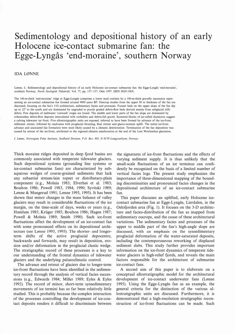
Fig. '2. O A. Topographic map of the ice<ontact submarine fan at Egge-Lyngås, Lierdalen palaeofjord, showing the position of sections 1-9 (black lines). Sections
1-3 are seismic section and sections 4-9 are outcrop sections. The dotted line indicates the present-day highest morphological part of the ice<ontact fan. The
Schmidt-ne! stereoplots show prog)acial thrusts at Egge and Lyngås (data in lower-hemisphere projection). O B-D. Interpretation of seismic sections 1-3. correlated
with electric depth conductivity and drilling wells (after Stokke 1981). Black dot in Fig. B represents an excavation south of the main section (see text).
140 /. Lønne NORSK GEOLOGISK TIDSSKRIFT 77 (1997)
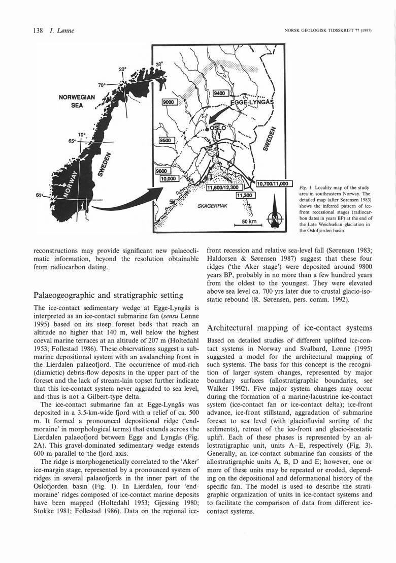
ICE·CONTACT UNDERWATER FAN ....---ICE-DISTAL SLOPE -------FAN TOP --ICE-PROXIMAL SLOPE -------.
RESULTANT POSTGLACIAL SURFACE APPARENT ICE-CONTACT SURFACE
FINAL ICE-coNTEMPORANEOUS MORPHOI.OGICAL SURFAce
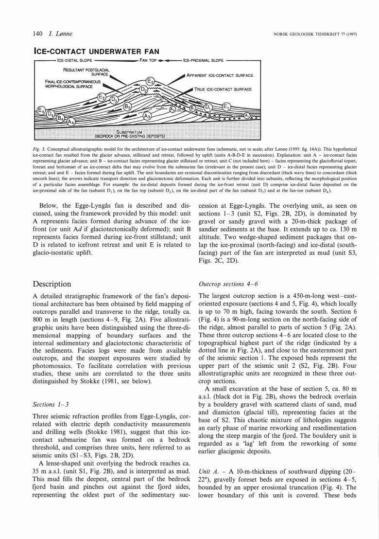
Fig. 3. Conceptual allostratigraphic model for the architecture of ice-contact underwater fans (schematic, not to scale; after Lønne (1995: fig. 14A)). This hypothetical
ice-contact fan resulted from the glacier advance, stillstand and retreat, followed by uplift (units A-B-D-E in succession). Explanation: unit A - ice-contact facies representing glacier advance; unit B - ice-contact facies representing glacier stillstand or retreat; unit C (not included here) - facies representing the glacioftuvial topset,
foreset and bottomset of an ice-contact delta that may evolve from the submarine fan (irrelevant in the present case); unit D - ice-distal facies representing glacier
retreat; and unit E - facies formed during fan uplift. The unit boundaries are erosional discontinuities ranging from discordant (thick wavy lines) to concordant (thick smooth lines); the arrows indicate transport direction and glaciotectonic deformation. Each unit is further divided into subunits, reftecting the morphological position
of a particular facies assemblage. For example: the ice-distal deposits formed during the ice-front retreat (unit D) comprise ice-distal facies deposited on the
ice-proximal side of the fan (subunit D1 ), on the fan top (subunit D2), on the ice-distal part of the fan (subunit D3) and at the fan-toe (subunit 04).
Below, the Egge-Lyngås fan is described and discussed, using the framework provided by this model: unit A represents facies formed during advance of the icefront (or unit Ad if glaciotectonically deformed); unit B represents facies formed during ice-front stillstand; unit O is related to icefront retreat and unit E is related to glacio-isostatic uplift.
Description
A detailed stratigraphic framework of the fan's depositional architecture has been obtained by field mapping of outcrops parallel and transverse to the ridge, totally ca. 800 m in length (sections 4-9, Fig. 2A). Five allostratigraphic units have been distinguished using the three-dimensional mapping of boundary surfaces and the internal sedimentary and glaciotectonic characteristic of the sediments. Facies logs were made from available outcrops, and the steepest exposures were studied by photomosaics. To facilitate correlation with previous studies, these units are correlated to the three units distinguished by Stokke ( 198 1, see below).
Sections 1-3
Three seismic refraction profiles from Egge-Lyngås, correlated with electric depth conductivity measurements and drilling wells (Stokke 198 1 ), suggest that this icecontact submarine fan was formed on a bedrock threshold, and comprises three units, here referred to as seismic units (S l -S3, Figs. 2B, 20).
A lense-shaped unit overlying the bedrock reaches ca. 35 m a.s.l. (unit S l , Fig. 2B), and is interpreted as mud. This mud fills the deepest, central part of the bedrock fjord basin and pinches out against the fjord sides, representing the oldest part of the sedimentary suc-
cession at Egge-Lyngås. The overlying unit, as seen on sections 1-3 (unit S2, Figs. 2B, 20), is dominated by gravel or sandy gravel with a 20-m-thick package of sandier sediments at the base. It extends up to ca. 130 m altitude. Two wedge-shaped sediment packages that onlap the ice-proximal (north-facing) and ice-distal (southfacing) part of the fan are interpreted as mud (unit S3, Figs. 2C, 20).
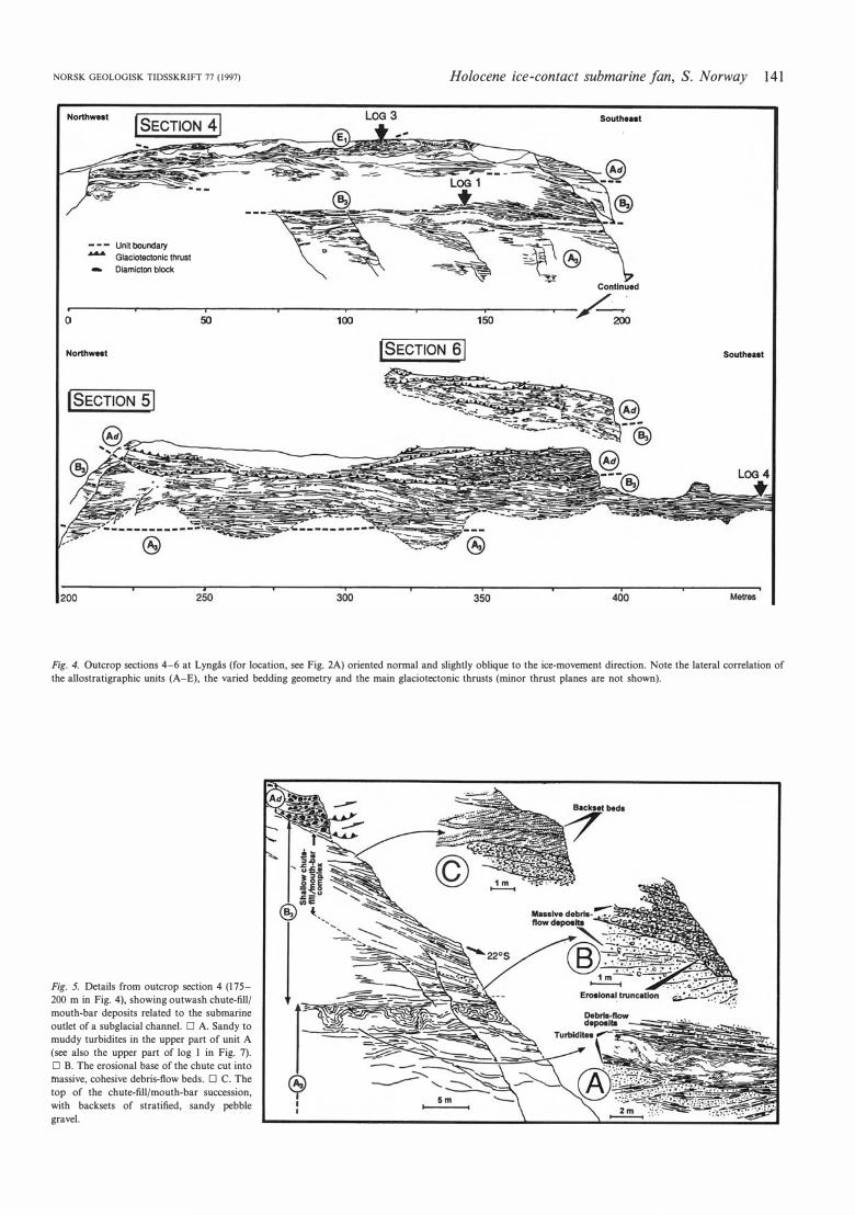
Outcrop sections 4-6
The !argest outcrop section is a 450-m-long west-eastoriented exposure (sections 4 and 5, Fig. 4), which locally is up to 70 m high, facing towards the south. Section 6 (Fig. 4) is a 90-m-long section on the north-facing side of the ridge, almost parallel to parts of section 5 (Fig. 2A). These three outcrop sections 4-6 are located dose to the topographical highest part of the ridge (indicated by a dotted line in Fig. 2A), and dose to the easternmost part of the seismic section l . The exposed beds represent the upper part of the seismic unit 2 (S2, Fig. 2B). Four allostratigraphic units are recognized in these three outcrop sections.
A small excavation at the base of section 5, ca. 80 m a.s.l. (black dot in Fig. 2B), shows the bedrock overlain by a bouldery gravel with scattered dasts of sand, mud and diamicton (glacial till), representing facies at the base of S2. This chaotic mixture of lithologies suggests an early phase of marine reworking and resedimentation along the steep margin of the fjord. The bouldery unit is regarded as a 'lag' left from the reworking of some earlier glacigenic deposits.
Unit A. - A 10-m-thickness of southward dipping (20-220), gravelly foreset beds are exposed in sections 4-5, bounded by an upper erosional truncation (Fig. 4). The lower boundary of this unit is covered. These beds
NORSK GEOLOGISK TIDSSKRIFT 77 (1997) Holocene ice-contact submarine fan, S. Norway
Northw•t
-
Unit boundary
Glaciotectonic thrust
Diamicton block
Southe .. t
Contlnued
or-------�--------s'o --------�-------1o�o--------�------- 1Tso--------�-� 2oo
Northw•t
lSECTION 51
Southeaat
14 1
Fig. 4. Outcrop sections 4-6 at Lyngås (for location, see Fig. 2A) oriented normal and slightly oblique to the ice-movement direction. Note the lateral correlation of
the allostratigraphic units (A-E), the varied bedding geometry and the main glaciotectonic thrusts (minor thrust planes are not shown).
Fig. 5. Details from outcrop section 4 (175-
200 m in Fig. 4), showing outwash chute-fill/
mouth-bar deposits related to the submarine
outlet of a subglacial channel. O A. Sandy to
muddy turbidites in the upper part of unit A
(see also the upper part of log l in Fig. 7).
O B. The erosional base of the chute cut in to
massive, cohesive debris-ftow beds. O C. The
top of the chute-fill/mouth-bar succession,
with backsets of stratified, sandy pebble
grave!.
142 /. Lønne
DETAILS
@
are correlated with the middle part of unit S2 which is underlain by a sandier, lower part of unit S2 and mud unit Sl (Figs. 2B, 20), suggesting a 65-m-thick coarsening-upward succession of which the uppermost 10 m is exposed and described below.
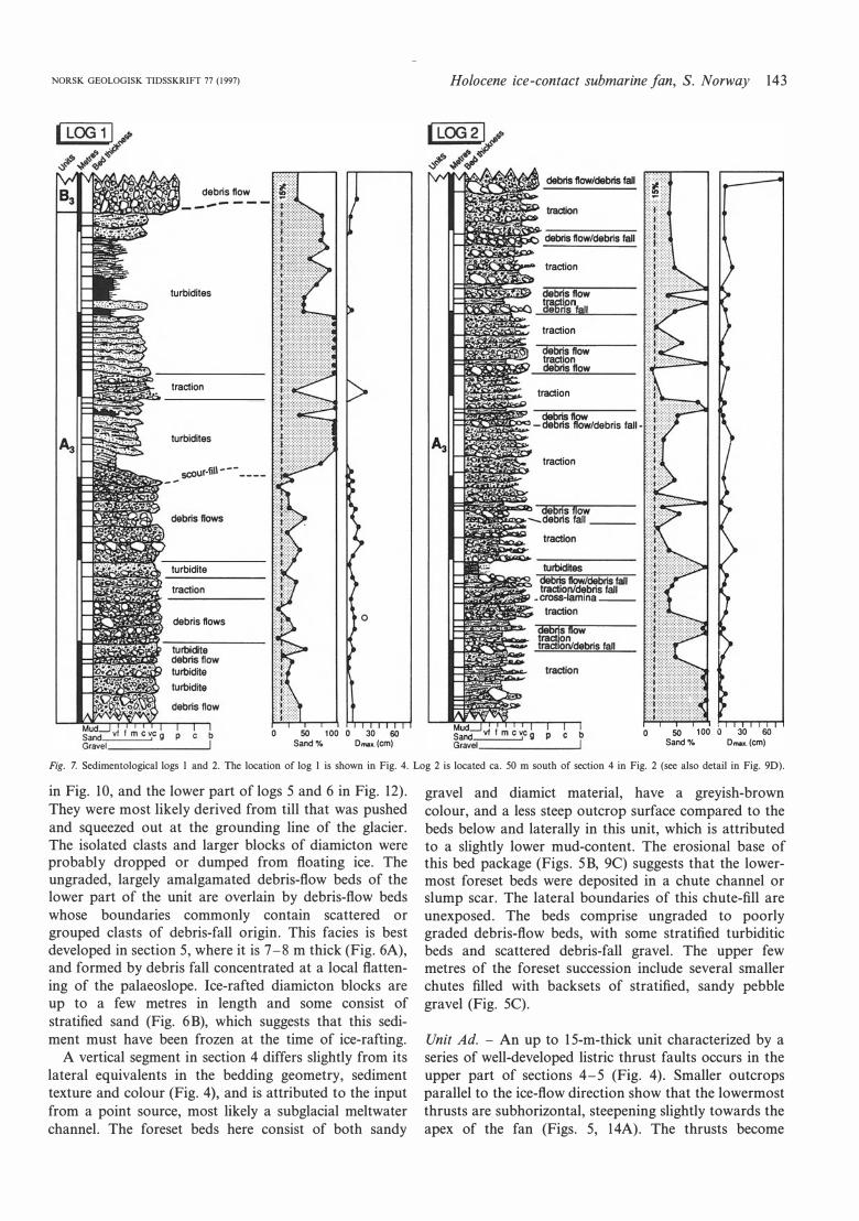
The outcrops show large variations in the sediment texture and bedding geometry, both laterally and vertically (Figs. 5, 6). Generally, these beds are dominated by ungraded to poorly graded gravelly deposits up to a few decimetres in thickness (log l, Fig. 7), interpreted as debris-flow deposits. Their yellowish-brown matrix colour and the steep outcrop surface suggest a relatively high mud content (the outcrop is inaccessible for direct sampling). Angular blocks, up to a few metres in length, occur as well as scattered outsized clasts, isolated or in clusters. An erosional truncation in section 4, cut a few metres into the underlying foreset deposits, represents a chute channel or slump scar filled with poorly bedded debris-flow deposits (Fig. 5).
A 4-m-thick package of deformed sandy and muddy turbidites in the upper part of unit A (see details in Fig. 5A), can be followed laterally for at !east 100 m before it wedges out. The lower turbidites seem to have filled in a shallow chute or slump scar (see the upper 3 m of unit A in log l, Fig. 7). This turbiditic succession is interpreted as a lateral equivalent of the package of sandy turbidites with abundant climbing-ripple cross-lamination exposed in the eastern part of section 5 (Figs. 4, 6). These
NORSK GEOLOGISK TIDSSKRIFT 77 (1997)
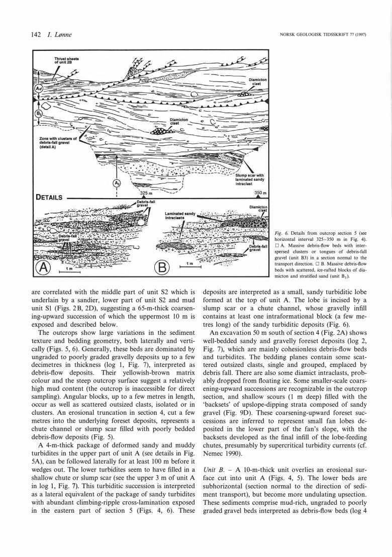
Fig. 6. Details from outcrop section 5 (see horizontal interval 325-350 m in Fig. 4).
O A. Massive debris-fiow beds with inter
spersed clusters or tongues of debris-fall
grave! (unit B3) in a section normal to the
transport direction. O B. Massive debris-fiow
beds with scattered, ice-rafted blocks of dia-
micton and stratified sand (unit B3 ).
deposits are interpreted as a small, sandy turbiditic lobe formed at the top of unit A. The lobe is incised by a slump scar or a chute channel, whose gravelly infill contains at !east one intraformational block (a few metres long) of the sandy turbiditic deposits (Fig. 6).
An excavation 50 m south of section 4 (Fig. 2A) shows well-bedded sandy and gravelly foreset deposits (log 2, Fig. 7), which are mainly cohesionless debris-flow beds and turbidites. The bedding planes contain some scattered outsized clasts, single and grouped, emplaced by debris fall. There are also some diamict intraclasts, probably dropped from floating ice. Some smaller-scale coarsening-upward successions are recognizable in the outcrop section, and shallow scours (l m deep) filled with the 'backsets' of upslope-dipping strata composed of sandy grave! (Fig. 90). These coarsening-upward foreset successions are inferred to represent small fan lobes deposited in the lower part of the fan's slope, with the backsets developed as the final infill of the lobe-feeding chutes, presumably by supercritical turbidity currents (cf. Nemec 1990).
Unit B. - A 10-m-thick unit overlies an erosional surface cut into unit A (Figs. 4, 5). The lower beds are subhorizontal (section normal to the direction of sediment transport), but become more undulating upsection. These sediments comprise mud-rich, ungraded to poorly graded grave! beds interpreted as debris-flow beds (log 4
NORSK GEOLOGISK TIDSSKRIFT 77 (1997)
debrisflow
turbidites
traction
turbidites
scour-li\1-------
turbidite
traction
debrisflows
o 50 100 o 30 60 Sand% Dmu. (cm)
Holocene ice-contact submarine fan, S. Norway 143
traction
debrisflow tractløn deons fall traction
dibris flow traction debris flow
traction
-= '11:,/debris fall
traction
o 50 100 o 30 60 Sand% Dmu. (cm)
Fig. 7. Sedimentological logs l and 2. The location of log l is shown in Fig. 4. Log 2 is located ca. 50 m south of section 4 in Fig. 2 (see also detail in Fig. 90).
in Fig. 10, and the 1ower part of 1ogs 5 and 6 in Fig. 12). They were most likely derived from till that was pushed and squeezed out at the grounding line of the glacier. The isolated clasts and Iarger blocks of diamicton were probab1y dropped or dumped from floating ice. The ungraded, largely amalgamated debris-flow beds of the lower part of the unit are overlain by debris-flow beds whose boundaries commonly contain scattered or grouped clasts of debris-fall origin. This facies is best developed in section 5, where it is 7-8 m thick (Fig. 6A), and formed by debris fall concentrated at a local flattening of the palaeoslope. lce-rafted diamicton blocks are up to a few metres in length and some consist of stratified sand (Fig. 6B), which suggests that this sediment must have been frozen at the time of ice-rafting.
A vertical segment in section 4 differs slightly from its lateral equivalents in the bedding geometry, sediment texture and colour (Fig. 4), and is attributed to the input from a point source, most likely a subglacial meltwater channel. The foreset beds here consist of both sandy
gravel and diamict material, have a greyish-brown colour, and a less steep outcrop surface compared to the beds below and laterally in this unit, which is attributed to a slightly lower mud-content. The erosional base of this bed package (Figs. 5B, 9C) suggests that the Iowermost foreset beds were deposited in a chute channel or slump scar. The lateral boundaries of this chute-fill are unexposed. The beds comprise ungraded to poorly graded debris-flow beds, with some stratified turbiditic beds and scattered debris-fall gravel. The upper few metres of the foreset succession include several smaller chutes filled with backsets of stratified, sandy pebble gravel (Fig. 5C).
Unit Ad. - An up to 15-m-thick unit characterized by a series of well-developed Iistric thrust faults occurs in the upper part of sections 4-5 (Fig. 4). Smaller outcrops parallel to the ice-flow direction show that the lowermost thrusts are subhorizontal, steepening slightly towards the apex of the fan (Figs. 5, 14A). The thrusts become
144 /. Lønne NORSK GEOLOGISK TIDSSKRIFT 77 (1997)
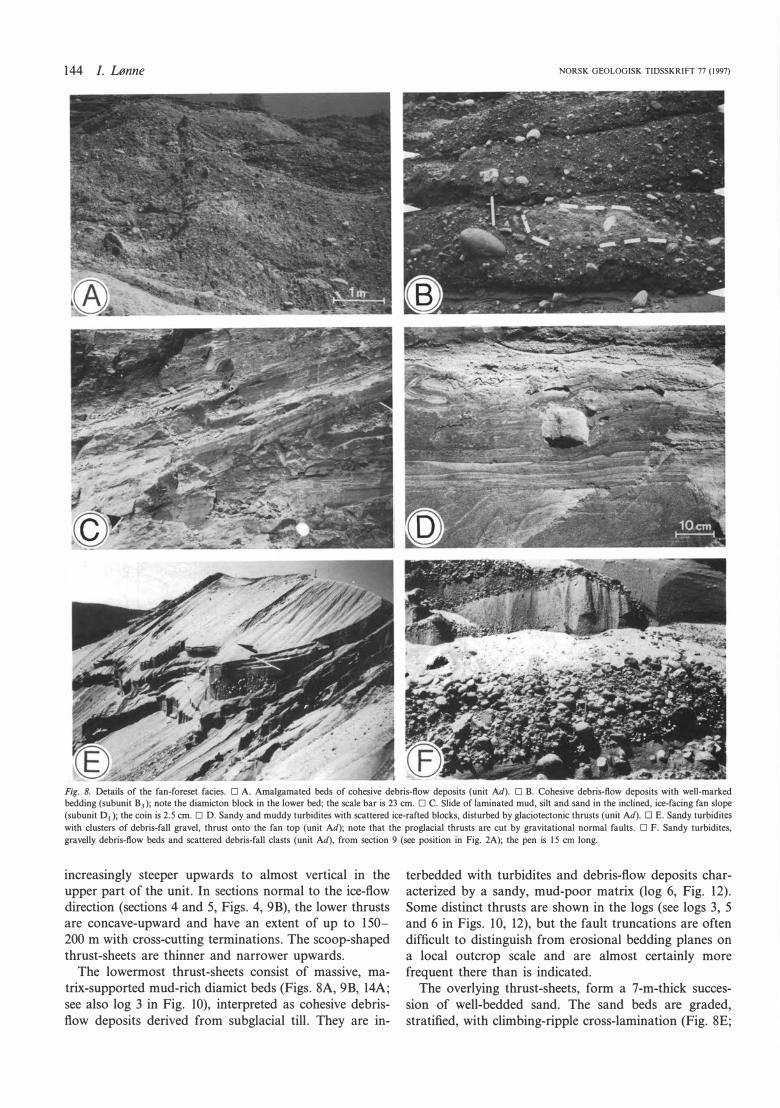
Fig. 8. Details of the fan-foreset facies. O A. Amalgamated beds of cohesive debris-ftow deposits (unit Ad). O B. Cohesive debris-ftow deposits with weU-marked bedding (subunit B3 ); note the diamicton block in the lower bed; the scale bar is 23 cm. O C. Slide of laminated mud, silt and sand in the inclined, ice-facing fan slop(, (subunit 01 ); the coin is 2.5 cm. O D. Sand y and muddy turbidites with scattered ice-rafted blocks, disturbed by glaciotectonic thrusts (unit Ad). O E. Sandy turbidites
with clusters of debris-fall grave!, thrust onto the fan top (unit Ad); note that the proglacial thrusts are cut by gravitational normal faults. O F. Sandy turbidites,
gravelly debris-ftow beds and scattered debris-fall clasts (unit Ad), from section 9 (see position in Fig. 2A); the pen is 15 cm long.
increasingly steeper upwards to almost vertical in the upper part of the unit. In sections normal to the ice-fiow direction (sections 4 and 5, Figs. 4, 9B), the lower thrusts are concave-upward and have an extent of up to 150-200 m with cross-cutting terminations. The scoop-shaped thrust-sheets are thinner and narrower upwards.
The lowermost thrust-sheets consist of massive, matrix-supported mud-rich diamict beds (Figs. SA, 9B, 14A; see also log 3 in Fig. 10), interpreted as cohesive debrisfiow deposits derived from subglacial till. They are in-
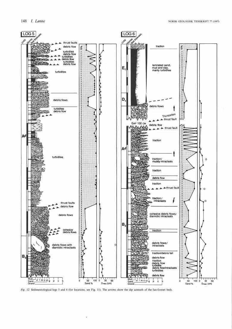
terbedded with turbidites and debris-fiow deposits characterized by a sandy, mud-poor matrix (log 6, Fig. 12). Some distinct thrusts are shown in the logs (see logs 3, 5 and 6 in Figs. l O, 12), but the fault truncations are often difficult to distinguish from erosional bedding planes on a local outcrop scale and are almost certainly more frequent there than is indicated.
The overlying thrust-sheets, form a 7-m-thick succession of well-bedded sand. The sand beds are graded, stratified, with climbing-ripple cross-lamination (Fig. SE;
NORSK GEOLOGISK TIDSSKRIFT 77 (1997) Holocene ice-contact submarine fan, S. Norway 145
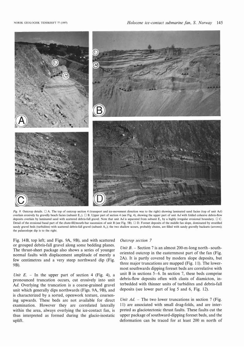
Fig. 9. Outcrop details. O A. The top of outcrop section 4 (transport and ice-movement direction was to the right) showing laminated sand facies (top of unit Ad)
overlain erosively by gravelly beach facies (subunit E1 ). O B. Upper part of section 4 (see Fig. 4), showing the upper part of unit Ad with folded cohesive debris-ftow
deposits overlain by laminated sand with scattered debris-fall grave!. Note that unit Ad is separated from subunit E1 by a highly irregular erosional boundary. O C.
Detail of the erosional basal part of the chute-fill/mouth-bar succession of unit B (see Fig. 5B). O D. Foreset deposits of the middle fan slope, dominated by stratified
sandy grave! beds (turbidites) with scattered debris-fall grave! (subunit A3 ); the two shallow scours, probably chutes, are filled with sandy gravelly backsets (arrows);
the palaeoslope dip is to the right.
Fig. 14B, top left; and Figs. 9A, 9B), and with scattered or grouped debris-fall gravel along some bedding planes. The thrust-sheet package also shows a series of younger normal faults with displacement amplitude of merely a few centimetres and a very steep northward dip (Fig. 9B).
Unit E. - In the upper part of section 4 (Fig. 4), a pronounced truncation occurs, cut erosively into unit Ad. Overlying the truncation is a coarse-grained gravel unit which generally dips northwards (Figs. 9A, 9B), and is characterized by a sorted, openwork texture, coarsening upwards. These beds are not available for direct examination. However they are correlated laterally within the area, always overlying the ice-contact fan, is thus interpreted as formed during the glacio-isostatic uplift.
Outcrop section 7 Unit B. - Section 7 is an almost 200 -m-long north-southoriented outcrop in the easternmost part of the fan (Fig. 2A). It is partly covered by modem slope deposits, but three major truncations are mapped (Fig. Il). The lowermost southwards dipping foreset beds are correlative with unit B in sections 5-6. In section 7, these beds comprise debris-flow deposits often with clasts of diamicton, interbedded with thinner units of turbidites and debris-fall deposits (see lower part of log 5 and 6, Fig. 12).
Unit Ad. - The two lower truncations in section 7 (Fig. Il) are associated with small drag-folds, and are interpreted as glaciotectonic thrust faults. These faults cut the upper package of southward-dipping foreset beds, and the deformation can be traced for at least 200 m north of
146 /. Lønne
debrisflow
4 4 4 thrust fault
traction
.._ 4 .t. thrust fault traction
debrisflow
traction
debrisflow/ diamictic intracfasts
turbidites debris flows with diamictic intracfasts
debris flow
traction
debris flow
debris flows
traction debrisflow
traction
o
50 100 o 30 60 Sand% O max. (cm)
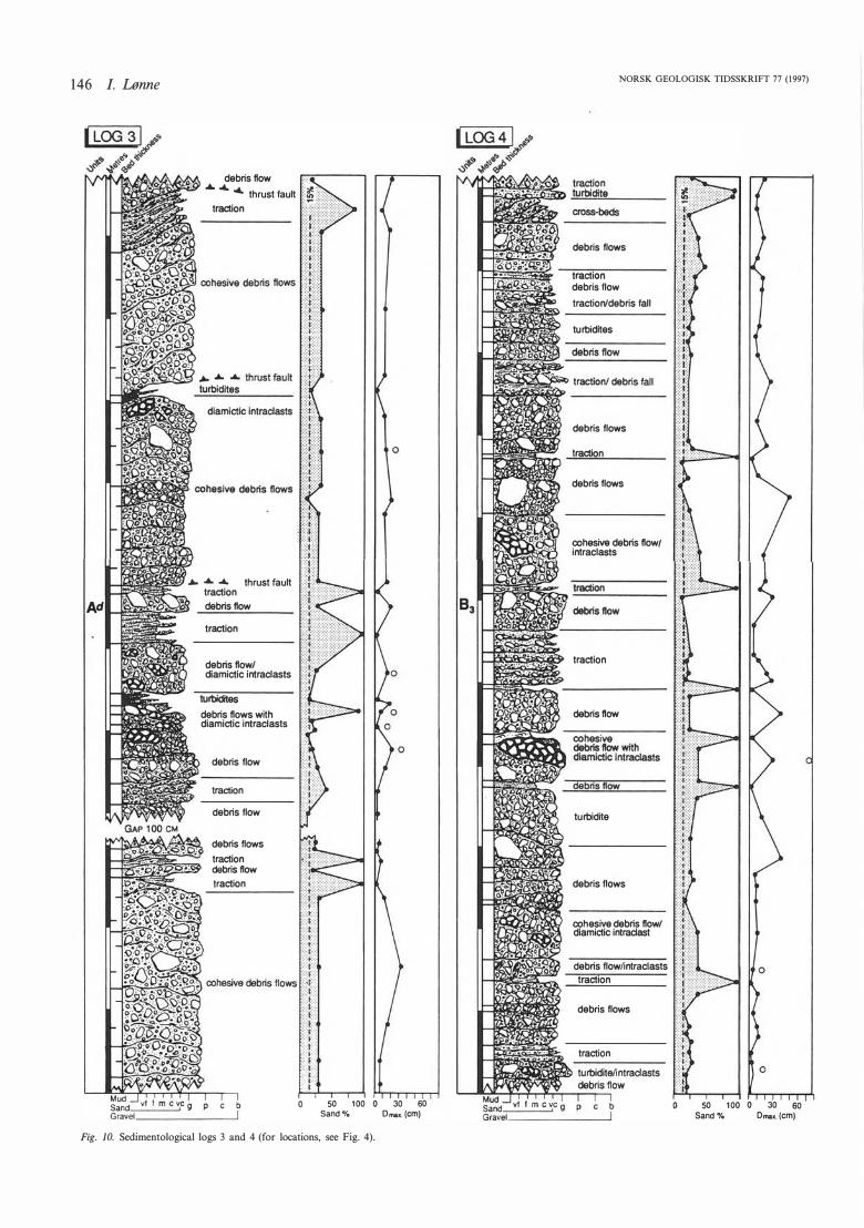
Fig. 10. Sedimentological logs 3 and 4 (for locations, see Fig. 4).
NORSK GEOLOGISK TIDSSKRIFT 77 (1997)
debris flows
traction
debrisflow
traction/debris fall
turbidites
debris flows
traction
debrisflows
cohesive debris flow/ intraclasts
traction
debris ftow
turbidite
debris flows
cohesive debris flow/ diamictic intracfast
debris flowlintracfasts
traction
debris flows
traction
50 100 o 30 60 Sand% Dmu (cm)
NORSK GEOLOGISK TIDSSKRIFT 77 (1997) Holocene ice-contact submarine fan, S. Norway 147
------ --- --------
�-
rt;---�?:���---
..§���Y--�---
______ ___ .. _ .. _��-� "<'"--��� � .::::---:- --·-�� l ·-----� l �--:::/ '
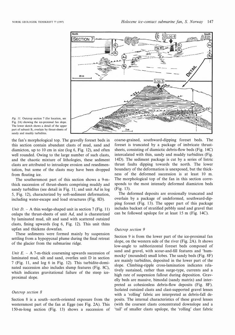
Fig. Il. Outcrop section 7 (for location, see
Fig. 2A) showing the ice-proximal fan slope.
The lower sketch shows a detail of the upper
part of subunit B3 overlain by thrust·sheets of
sandy and muddy turbidites.
25m
the fan's morphological top. The gravelly foreset beds in this section contain abundant clasts of mud, sand and diamicton, up to 10 cm in size (log 6, Fig. 12), and often well rounded. Owing to the large number of such clasts, and the chaotic mixture of lithologies, these sediment clasts are attributed to intraslope erosion and resedimentation, but some of the clasts may have been dropped from floating ice.
The southernmost part of this section shows a 9-mthick succession of thrust-sheets comprising muddy and sandy turbidites (see detail in Fig. 1 1; and unit Ad in log 5, Fig. 12), characterized by soft-sediment deformation, including water-escape and load structures (Fig. 80).
Unit D. - A thin wedge-shaped unit in section 7 (Fig. 1 1) onlaps the thrust-sheets of unit Ad, and is charaterized by laminated mud, silt and sand with scattered outsized clasts, tining upwards (log 6, Fig. 12). This unit thins upfan and thickens downfan.
These sediments were formed mainly by suspension settling from a hypopycnal plume during the final retreat of the glacier from the submarine ridge.
Unit E. - A 7-m-thick coarsening upwards succession of laminated mud, silt and sand, overlies unit O in section 7 (Fig. 1 1, and log 6 in Fig. 12). This turbidite-dominated succession also includes slump features (Fig. 8C), which indicates gravitational failure of the steep iceproximal slope.
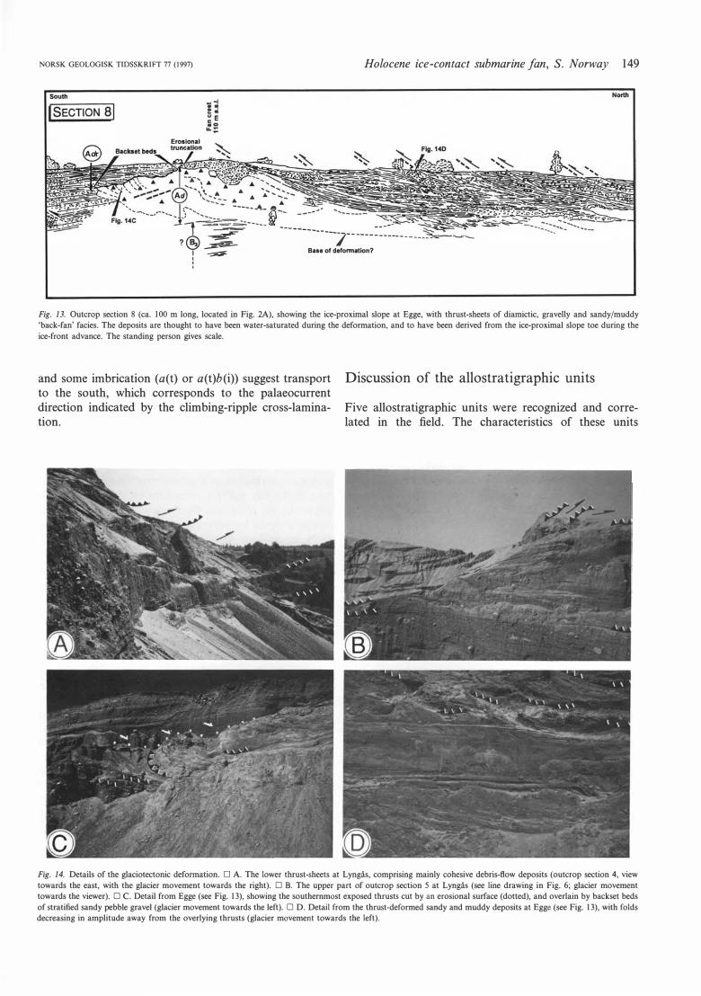
Outcrop section 8 Section 8 is a south-north-oriented exposure from the westernmost part of the fan at Egge (see Fig. 2A). This 150-m-long section (Fig. 13) shows a succession of
coarse-grained, southward-dipping foreset beds. The foreset is truncated by a package of imbricate thrustsheets, consisting of diamictic debris-flow beds (Fig. 14C) intercalated with thin, sandy and muddy turbidites (Fig. 140). The sediment package is cut by a series of listric thrust faults dipping towards the north. The lower boundary of the deformation is unexposed, but the thickness of the deformed succession is at least 10 m. The morphological top of the fan in this section corresponds to the most intensely deformed diamicton beds (Fig. 13).
The deformed deposits are erosionally truncated and overlain by a package of undeformed, southward-dipping foreset (Fig. 13). The upper part of this package includes backset of stratified pebbly sand and grave! that can be followed upslope for at least 15 m (Fig. 14C).
Outcrop section 9 Section 9 is from the lower part of the ice-proximal fan slope, on the western side of the river (Fig. 2A). It shows 1ow-angle to subhorizontal foreset beds composed of sand and grave!, with scour-and-fill features and 'hummocky' (mounded) small lobes. The sandy beds (Fig. 8F) are mainly turbidites, deposited in the lower part of the slope. Climbing-ripple cross-lamination indicates relatively sustained, rather than surge-type, currents and a high rate of suspension fallout during deposition. Gravelly beds are massive, bimodal (sandy matrix) and interpreted as cohesionless debris-flow deposits (Fig. 8F). Isolated outsized clasts and clast-supported grave! lenses with a 'rolling' fabric are interpreted as debris-fall deposits. The internal characteristics of these grave! lenses (with the coarsest clasts concentrated downslope and a 'tail' of smaller clasts upslope, the 'rolling' clast fabric
148 l. Lønne
thrust faults "....,.."""r----. debris flow
turbidites-
debris flows
turbid�es debrisflow
turbidites
thrust faults
debris flow
debris flows
cohesive debrisflows
debris flows with diamictic intraclasts
50 100 Sand%
; !
� ,.
� '
o 30 60 Dmox.(cm)
o
NORSK GEOLOGISK TIDSSKRIFT 77 (1997)
traction
laminated sand, mud and ela y, mainly turbid�es
-----
debris flows
traction
traction / muddy intraclasts
traction
debris ftow
traction
t
t
cohesive debris flowst diamictic intraclasts
traction
debris flows/ intraclasts
traction/debris fall
debris ftow traction debris flow tu�e debris ftowlintracfasts turbidites
o
o
50 100 o 30 60 Sand % Dmax. (cm)
Fig. 12. Sedimentological logs 5 and 6 (for locations, see Fig. Il). The arrows show the dip azimuth of the fan-foreset beds.
NORSK GEOLOGISK TIDSSKRIIT 77 (1997)
South
ISEcrloN al Eroslonal
.. :• ... Å • ".. .... -::_ ............. <:.:.-_- �---�_ ... _ It�. }
Holocene ice-contact submarine fan, S. Norway 149
l --�------ !'« --------? ® $- ____ ] __ _______________ ___
1 � Base of deformatJon? i '
Fig. 13. Outcrop section 8 (ca. 100 m lang, located in Fig. 2A), showing the ice-proximal slope at Egge, with thrust-sheets of diamictic, gravelly and sandy/muddy
'back-fan' facies. The deposits are thought to have been water-saturated during the deformation, and to have been derived from the ice-proximal slope toe during the
ice-front advance. The standing person gives scale.
and some imbrication (a(t) or a(t)b (i)) suggest transport to the south, which corresponds to the palaeocurrent direction indicated by the climbing-ripple cross-lamination.
Discussion of the allostratigraphic units
Five allostratigraphic units were recognized and correlated in the field. The characteristics of these units
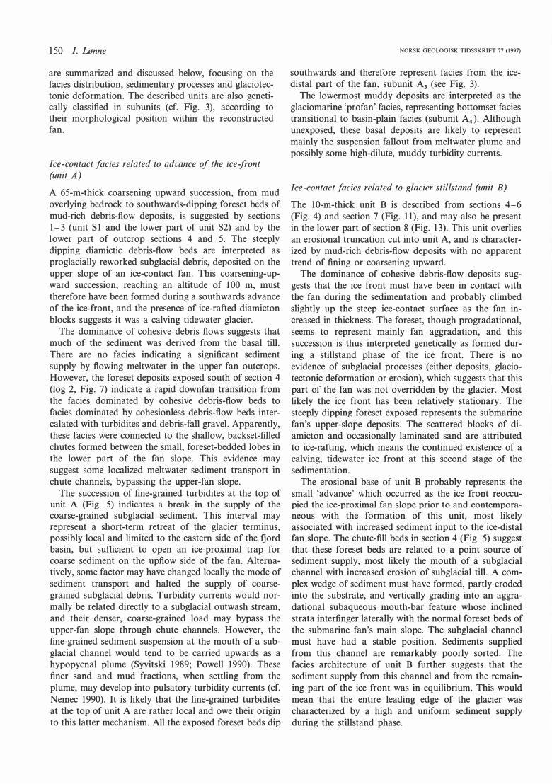
Fig. 14. Details of the glaciotectonic deformation. D A. The lower thrust-sheets at Lyngås, comprising mainly cohesive debris-ftow deposits (outcrop section 4, view
towards the east, with the glacier movement towards the right). D B. The upper part of outcrop section 5 at Lyngås (see line drawing in Fig. 6; glacier movement
towards the viewer). D C. Detail from Egge (see Fig. 13), showing the southemmost exposed thrusts cut by an erosional surface (dotted), and overlain by backset beds
of stratified sandy pebble grave! (glacier movement towards the left). D D. Detail from the thrust-deformed sandy and muddy deposits at Egge (see Fig. 13), with folds
decreasing in amplitude away from the overlying thrusts (glacier movement towards the left).
150 l. Lønne
are summarized and discussed below, focusing on the facies distribution, sedimentary processes and glaciotectonic deformation. The described units are also genetically classified in subunits (cf. Fig. 3), according to their morphological position within the reconstructed fan.
Jce-contact facies related to advance of the ice-front (unit A)
A 65-m-thick coarsening upward succession, from mud overlying bedrock to southwards-dipping foreset beds of mud-rich debris-flow deposits, is suggested by sections 1-3 (unit Sl and the lower part of unit S2) and by the Iower part of outcrop sections 4 and 5. The steeply dipping diamictic debris-flow beds are interpreted as proglacially reworked subglacial debris, deposited on the upper slope of an ice-contact fan. This coarsening-upward succession, reaching an altitude of l 00 m, must therefore have been formed during a southwards advance of the ice-front, and the presence of ice-rafted diamicton blocks suggests it was a calving tidewater glacier.
The dominance of cohesive debris flows suggests that much of the sediment was derived from the basal till. There are no facies indicating a significant sediment supply by flowing meltwater in the upper fan outcrops. However, the foreset deposits exposed south of section 4 (log 2, Fig. 7) indicate a rapid downfan transition from the facies dominated by cohesive debris-flow beds to facies dominated by cohesionless debris-flow beds intercalated with turbidites and debris-fall gravel. Apparently, these facies were connected to the shallow, backset-filled chutes formed between the small, foreset-bedded lobes in the lower part of the fan slope. This evidence may suggest some localized meltwater sediment transport in chute channels, bypassing the upper-fan slope.
The succession of fine-grained turbidites at the top of unit A (Fig. 5) indicates a break in the supply of the
coarse-grained subglacial sediment. This interval may represent a short-term retreat of the glacier terminus, possibly local and limited to the eastem side of the fjord basin, but sufficient to open an ice-proximal trap for coarse sediment on the upflow side of the fan. Altematively, some factor may have changed Iocally the mode of sediment transport and halted the supply of coarsegrained subglacial debris. Turbidity currents would normally be related directly to a subglacial outwash stream, and their denser, coarse-grained load may bypass the upper-fan slope through chute channels. However, the fine-grained sediment suspension at the mouth of a subglacial channel would tend to be carried upwards as a hypopycnal plume (Syvitski 1989; Powell 1990). These finer sand and mud fractions, when settling from the plume, may develop into pulsatory turbidity currents (cf. Nemec 1990). It is likely that the fine-grained turbidites at the top of unit A are rather local and owe their origin to this latter mechanism. All the exposed foreset beds dip
NORSK GEOLOGISK TIDSSKRIFT 77 (1997)
southwards and therefore represent facies from the icedistal part of the fan, subunit A3 (see Fig. 3).
The Iowermost muddy deposits are interpreted as the glaciomarine 'profan' facies, representing bottomset facies transitional to basin-plain facies (subunit A4). Although unexposed, these basal deposits are likely to represent mainly the suspension fallout from meltwater plume and possibly some high-dilute, muddy turbidity currents.
Ice-contact facies related to glacier stillstand (unit B)
The 10-m-thick unit B is described from sections 4-6 (Fig. 4) and section 7 (Fig. 11), and may also be present in the lower part of section 8 (Fig. 13). This unit overlies an erosional truncation cut into unit A, and is characterized by mud-rich debris-flow deposits with no apparent trend of tining or coarsening upward.
The dominance of cohesive debris-flow deposits suggests that the ice front must have been in contact with the fan during the sedimentation and probably climbed slightly up the steep ice-contact surface as the fan increased in thickness. The foreset, though progradational, seems to represent mainly fan aggradation, and this succession is thus interpreted genetically as formed during a stillstand phase of the ice front. There is no evidence of subglacial processes (either deposits, glaciotectonic deformation or erosion), which suggests that this part of the fan was not overridden by the glacier. Most likely the ice front has been relatively stationary. The steeply dipping foreset exposed represents the submarine fan's upper-slope deposits. The scattered blocks of diamicton and occasionally laminated sand are attributed to ice-rafting, which means the continued existence of a calving, tidewater ice front at this second stage of the sedimentation.
The erosional base of unit B probably represents the small 'advance' which occurred as the ice front reoccupied the ice-proximal fan slope prior to and contempora
neous with the formation of this unit, most likely associated with increased sediment input to the ice-distal fan slope. The chute-fill beds in section 4 (Fig. 5) suggest that these foreset beds are related to a point source of sediment supply, most likely the mouth of a subglacial channel with increased erosion of subglacial till. A complex wedge of sediment must have formed, partly eroded into the substrate, and vertically grading into an aggradational subaqueous mouth-bar feature whose inclined strata interfinger laterally with the normal foreset beds of the submarine fan's main slope. The subglacial channel must have had a stable position. Sediments supplied from this channel are remarkably poorly sorted. The facies architecture of unit B further suggests that the sediment supply from this channel and from the remaining part of the ice front was in equilibrium. This would mean that the entire leading edge of the glacier was characterized by a high and uniform sediment supply during the stillstand phase.
NORSK GEOLOGISK TIDSSKRIFT 77 (1997)
Ice-contact facies related to glacier advance -
proglacially-deformed facies (unit Ad)
This 15-m-thick thrust-dominated unit is described from sections 4-6 (Fig. 4), section 7 (Fig. 11) and section 8 (Fig. 13). Although unit Ad is quite distinctive and mappable, its exact boundaries are difficult to define in the outcrops. The spatia! distribution of the deformation was used to ascertain the geometry of the unit, the stratigraphic position of the deformational phase and its role in the development of the fan's architecture.
The thrust-sheets have been displaced southwards (see thrust-plane plots in Fig. 2A), onto unit B, and outcrops parallel to the ice-flow direction (sections 7 and 8, Fig. 2A) show that the thrust planes can be traced for at !east 250 m. The thrust-sheets vary in thickness from a few metres to ca. 10 m (Fig. 4). The orientation of the imbricated thrust-sheets indicates that the deformation occurred at the front of a southward-advancing glacier (cf. Croot 1988b; Fernlund 1988). The 1eading edge of the glacier probably came close to the fan's crest, but did not override the fan.
The facies of the thrusted sheets vary from ice-proximal facies of diamictic debris-flow deposits (base of unit Ad in section 4-6), to sandy turbidites with debris-fall grave! representing lower s1ope facies (top of the unit in sections 4-5) to laminated mud (northernmost part of section 8). These facies suggest that the thrusted sheets were derived mainly from the lower part of the fan's ice-proximal slope. The turbidites indicate sustained currents with a high rate of suspension fallout, which suggests deposition close to the submarine meltwater channel outlet and probably under the rising buoyant plume.
The wedge of undeformed deposits in section 8 (subunit Adr in Fig. 13) is interpreted as the product of resedimentation of unit Ad, which was probably subject to erosion by gravitational processes and meltwater flow during the proglacial deformation. Alternatively, this subunit may have been deposited during the postglacial regression (unit E, discussed below). However, the facies of subunit Adr are lithologically similar to, and conformable with, the underlying foreset facies of unit Ad, which suggests a close genetic association.
Northwards-dipping faults of the sand beds at the top of unit Ad in section 4 (Fig. 9B) are thought to be gravitational faults related to the synsedimentary extensional stress caused by the thrust-sheet piling across the morphological top of the submarine fan. This sandy succession can be correlated laterally with a 9-m-thick succession of thrust-sheets comprising muddy and sandy turbidites (see unit Ad in Fig. 11; see also log 5 in Fig. 12). The soft-sediment deformation in these turbidites, including water-escape and load structures (Fig. SD) may be a result of the ice-induced proglacial compression.
Permafrost conditions could not have been developed in these submarine deposits prior to the time of the deformation. The sediment must thus have been soft and
Holocene ice-contact submarine fan, S. Norway 151
water-saturated. Although glaciotectonic deformation was traditionally thought to be associated with permafrost conditions (e.g., Aber et al. 1989), recent studies have shown that similar deformation structures can form in softjunfrozen sediment (e.g., Eybergen 1987; Ingolfsson 1988; Owen 1988) and well below the sea leve! (e.g., Solheim & Pfirman 1985). The deformation of waterlogged soft sediment tends to be more influenced by lithofacies heterogeneities (cf. Aber et al. 1989), compared to the deformation in a frozen sediment. Therefore, the former deformation can easily be mistaken for gravitational deformation, which is also commonly associated with the steep ice-contact slopes and high sedimentation rates. The most competent beds (such as the cohesive debris-flow beds in the lower part of unit Ad, Fig. 9B) are commonly folded, whereas the less competent beds (such as the sandy turbidites) show mainly shear-deformation (Fig. SD).
The thrust-sheets in the present case are 150-200 m wide normal to the ice-flow direction, have concave-upward soles and have been displaced over at !east 250 m. The most critical factor that controls the extent of proglacial thrusting is the physiographic relationship between the glacier and the proglacial area, including the slope and relief of the proglacial area, the depth of weak sediment layers (decollement), the topographic relationship of the glacier snout to the proglacial sediment wedge, and the thickness of the ice-proximal part of the sediment wedge, relative to its ice-distal part (Aber et al. 1989). In the present case, the ice-contact fan had a high relief (avalanching slope) and a thickness of ca. 100 m in the head zone. There was probably also a considerable difference in altitude between the fan's base and the sole of the glacier just prior to the deformation phase. The sole of the glacier, as the leve! of maximum compression, was apparently in the lower part of the fan's ice-proximal slope, from where the sediment slices have been derived and thrust upon the fan's head and upper ice-distal slope.
The 3-D geometry of the thrust-sheets, as inferred from the outcrop sections, suggests that the morphology of unit Ad may be similar to sedimentary ridges at the front of modem glaciers. Such ridges are usually complex arrays of coalescent, smaller lobate ridges, related to the differential movement of ice-front segments (see Bybergen 1987; Croot 1988a, b). Much of the ice-front movement occurs along longitudinal crevasses, whose spacing may range from a few metres to several hundred metres (Owen 1988). For example, Ber (1987) has described a festoon pattern of ice-shoved ridges in the Polish Lowland. In the present case, the curvature of the main thrust faults in outcrop sections normal to the ice-flow direction suggests that a similar style of localized, lobate shoving might characterize the proglacial deformation of the Egge-Lyngås fan. The concave-upward, scoop-shaped geometry of the thrusts could be due to the fan topography. The crosscutting of thrust-sheets by the younger ones (Fig. 4) might further suggest some
152 /. Lønne
rapid shifting in the position of the Jongitudinal crevasses that controlled the ice-front's differential movement, resulting in considerable offset between the successive thrusts or thrust segments.
The zone of maximum compression probably corresponds to the strongly folded diamicton in section 8 at Egge (Fig. 13) and the imbricated thrust-sheets of sand and diamicton in sections 4 and 5 at Lyngås (Fig. 4). Near this zone, the thrusts are crosscut by numerous, small-amplitude normal faults, dipping southwards at Egge and northwards in section 4 at Lyngås. This suggests that the thrust-sheets have been emplaced onto the morphological crest of the fan, and subsequentially affected by gravitational stresses in accordance with the fan's topography. The thrust-sheets probably terminated at the free surface of the submarine fan, as suggested by their erosional truncation and the Jack of deformation in the overlying deposits. The thrust-sheet emplacement was probably accompanied by considerable resedimentation, resulting in a Jobe of secondary mass-flow deposits (subunit Adr, see Fig. 13) that downlapped the fan's ice-distal slope.
lee-distal facies related to glacier retreat (unit D) These y o unger deposits are only exposed in section 7, which represents the ice-proximal part of the fan. These northward-dipping beds therefore represent subunit 01• The fining-upward succession onlaps the primary icecontact slope and overlies directly the thrust-sheets of unit Ad. It is inferred to have been formed mainly by the suspension settling from a hypopycnal plume during the final retreat of the glacier from the submarine ridge. Some of the sand and mud was also derived from the resedimentation processes on the ice-proximal slope, including 'ponded' turbidity currents and debris flows. Scattered outsized clasts suggest that a calving, tidewater ice terminus was still active during this retreat phase.
Facies related to fan uplift (unit E)
The northward di p of these beds and the regressive facies succession indicate shoreline progradation into the shallowing, ice-proximal topographic low left by the retreating glacier. The beds onlap the former ice-proximal slope of the fan and thus, genetically, represent subunit E1 (see Fig. 3). These beds were formed by resedimentation on the abandoned fan. They were deposited dose to the emerging shoreline, representing beach face facies.
Depositional and deformational history of the Egge-Lyngås ice-contact fan
lee-front oscillation I
The 65-m-thick coarsening-upwards succession overlying the fjord-floor bedrock, was formed during a southwards
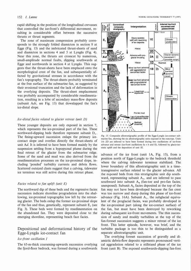
Generallzed composlte stratlgraphy
NORSK GEOLOGISK TIDSSKRIFT 77 (1997)
lnterpretatlon
Glacio-isostatic uplift with reworking 1 E
of fan deposits
Hiatus
Advance with proglacial thrusting
Lowermost_ -- exposures
Pro-fan mud
Fig. 15. Composite allostratigraphic profile of the Egge-Lyngås ice-contact sub
marine fan, showing the six allostratigraphic units exposed in the outcrops. Units
IA-20 are inferred to have been formed during two oscillations of ice-front
advance and retreat (ice-front oscillations la+ b and Il), followed by glacio-iso
static uplift and the deposition of unit lE.
advance of the ice front (unit l A, Fig. 15), from a position north of Egge-Lyngås to the bedrock threshold where the calving tidewater terminus stabilized. The lower boundary of this allostratigraphic unit is a timetransgressive surface related to the glacier advance. All the exposed beds from this stratigraphic unit dip southward, representing subunit A3 , and are inferred to pass southward into subunit A4 (fan-toe and pro-fan facies; unexposed). Subunit A2 facies deposited at the top of the fan may not have been developed because the fan crest was too narrow and sharp during this phase of ice-front advance (Fig. 16A). Subunit A1, the subglacial equivalent of the proglacial facies, was probably developed in the ice-proximal part (along the ice-contact surface) of the fan, but must have been destroyed by reworking during subsequent ice-front movements. The thin succession of sandy and muddy turbidites at the top of the fan-foreset succession suggests a minor retreat of the ice front. This latter episode, however, was brief, and the turbidite package is too thin to be distinguished as a separate allostratigraphic unit.
The overlying foreset succession of gravelly and diamictic debris-flow deposits represents pronounced vertical aggradation related to a stillstand phase of the ice front (unit B). The exposed southwards-dipping fan-fore
NORSK GEOLOGISK TIDSSKRIFT 77 (1997)
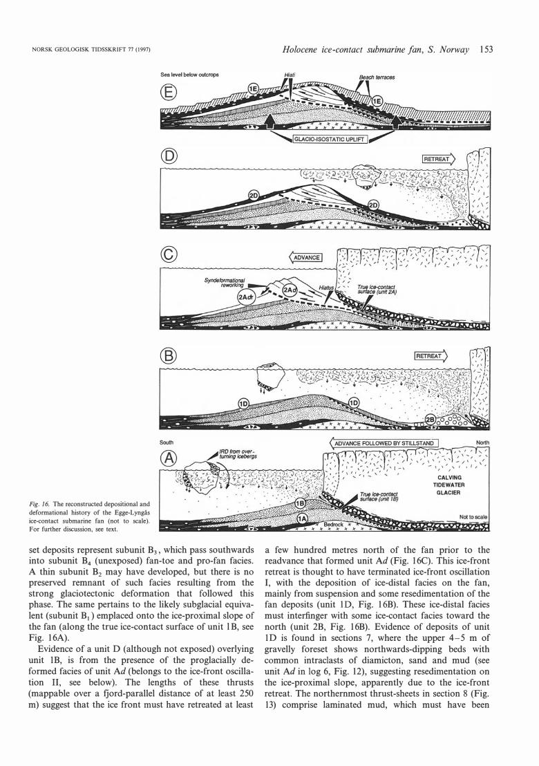
Fig. 16. The reconstructed depositional and
deformational history of the Egge-Lyngås
ice-contact submarine fan (not to scale).
For further discussion, see text.
Sea leve! below outcrops
@
©
®
set deposits represent subunit B3 , which pass southwards into subunit B4 (unexposed) fan-toe and pro-fan facies. A thin subunit B2 may have developed, but there is no preserved remnant of such facies resulting from the strong glaciotectonic deformation that followed this phase. The same pertains to the likely subglacial equivalent (subunit B1) emplaced onto the ice-proximal slope of the fan (along the true ice-contact surface of unit l B, see Fig. 16A).
Evidence of a unit D (although not exposed) overlying unit lB, is from the presence of the proglacially deformed facies of unit Ad (belongs to the ice-front oscillation Il, see below). The lengths of these thrusts (mappable over a fjord-parallel distance of at !east 250 m) suggest that the ice front must have retreated at least
Holocene ice-contact submarine fan, S. Norway 153
C AL VING TIDEWATER
GLACIER
a few hundred metres north of the fan prior to the readvance that formed unit Ad (Fig. l6C). This ice-front retreat is thought to have terminated ice-front oscillation l, with the deposition of ice-distal facies on the fan, mainly from suspension and some resedimentation of the fan deposits (unit ID, Fig. 16B). These ice-distal facies must interfinger with some ice-contact facies toward the north (unit 2B, Fig. 16B). Evidence of deposits of unit ID is found in sections 7, where the upper 4-5 m of gravelly foreset shows northwards-dipping beds with common intraclasts of diamicton, sand and mud (see unit Ad in log 6, Fig. 12), suggesting resedimentation on the ice-proximal slope, apparently due to the ice-front retreat. The northernmost thrust-sheets in section 8 (Fig. 13) comprise laminated mud, which must have been
154 l. Lønne
deposited prior to the readvance forming unit Ad. These presumably unit ID deposits are now found in unit Ad, being deformed and incorporated with other deposits during the subsequent readvance of the glacier. The ice-front oscillation that formed units lB and ID is distinguished as subcycle lb of ice-front oscillation I in the present reconstruction (Fig. 15). The lower boundary of unit lBl (although unexposed) would then represent the ice-contact surface of the ice-front stillstand phase (Fig. 16A).
The southward advance of the ice front that initiated ice-front oscillation I is thought to represent a phase of climatic stabilization or deterioration during the regional process of climatic amelioration that led to the relatively rapid deglaciation of the Oslofjorden basin. If it was a response to climate change, then the ice-front oscillation I (deposits equivalent of units lA-lB-lD) should be regionally correlatable and recognizable in the ice-contact systems in the adjacent fjords (this remains to be studied). The intervening episode of the ice-front movement separating parts la and lb of the ice-front oscillation I in all likelihood represents a local event of the glacier dynamics.
lee-front oscillation Il
lee-front oscillation Il formed the 10-15-m-thick succession of sedimentary thrust-sheets that constitute unit 2Ad. This unit is thus separated from the underlying unit lB by a hiatus (see Fig. 16C) even if chronostratigraphically short. In outcrop sections 4 and 5 (Fig. 4), the lower part of unit 2Ad comprises ice-contact debris-flow deposits, whereas the upper part consists of sandy turbidites interbedded with debris-fall gravel.
The stratigraphic position of the lower-fan foreset beds exposed in outcrop section 9 (Fig. SF) which were deposited towards the south, opposite of the fan inclinations, is based on the following reasoning: if these deposits were formed during the former phase of the ice-front advance (subcycle la, Fig. 15), they would have been in a subglacial position during the deposition of units lA and lB (Fig. 16A) and thus subject to strong glaciotectonic deformation and/or erosion. It is more likely that these southwards-dipping beds were formed when the ice front had temporarily retreated from the main fan at the end of ice-front oscillation I, forming a small, secondary ice-contact fan directly north of the main fan (unit 2B, Fig. 16B). This unit 2B-fan would further be deformed and displacedferoded during the ice re-advance in ice-front oscillation Il, and same of the deposits thrust upon the tap of the main fan.
The deposits representing the termination of ice-front oscillation Il, and the final retreat of the glacier from the Egge-Lyngås area are recorded as unit 2D (Fig. 16D), which comprises a fining-upward succession of laminated sand and mud with scattered ice-rafted debris, subunit D1• Their equivalents on the ice-distal fan slope (units D3-D 4 ) are unexposed.
NORSK GEOLOGISK TIDSSKRIFT 77 (1997)
Morphologically, the proglacially formed thrust-sheets of unit 2Ad may be equivalent to push moraines. Although several mechanisms may be implicated in the development of such push ridges, they are thought to be associated with ice-front advance, and commonly formed in association with glacial surges. Solheim (1991) demonstrated that similar ridges also formed in front of a glacier surging into a relatively deep (100 m) marine environment.
The proglacial thrusting related to the first part of ice-front oscillation Il is the only evidence of glaciotectonic deformation of this ice-contact fan, and the outcrops show no evidence that the glacier has ever overridden the fan. The small thickness of unit 2D (Fig. 16D) suggests that oscillation Il terminated with a relatively rapid retreat of the glacier. It is not unlikely that this oscillation represents a glacial surge, although there are no simple criteria to determine this from the outcrops. If oscillation Il represents a glacial surge (non-climatic advance), this phase of proglacial deformation should lack regional equivalents in the other ice-contact systems of the 'Aker stage' (this is yet to be studied). It can be concluded that unit 2Ad represents a pronounced advance of the glacier terminus, even though the duration of this episode and its triggering mechanism are unknown. The subsequent rapid retreat probably shifted the ice front to Mehren, 2.5 km north of the Egge-Lyngås area, where an almost completely glaciotectonized ridge of ice-contact deposits occurs. This rapid retreat may represent further amelioration of the regional climate.
The sea-level displacement curve for this region (Sørensen et al. 1990) suggests that the glacio-isostatic uplift in this area commenced well befare the deglaciation of the Oslofjorden basin (Scandinavian ice-sheet melting) bad been completed. The boundary between units D and E in this case represents the combined effects of glacier retreat and isostatic uplift. The gradual decline in glacigenic sediment input to the Lierdalen palaeofjord occurred concurrently with the resedimentation processes
on the fan surface and the fjord-margin slopes, caused by the uplift. Unit D shows a fining-upward trend, whereas unit E shows a coarsening-upward ane. Theoretically, the upper boundary of unit D represents the last input of glacial sediment. This boundary, however, may be difficult to identify precisely in an outcrop, because of the obliteration by sediment failures on the steep morphological surfaces of the abandoned fan.
Postdepositional modification of the fan
Unit E is a non-glacial sedimentary succession which, genetically, is not a part of the fan, but a product of the postdepositional modification of the fan morphology. However, the recognition of this allostratigraphic unit and its boundaries is important for the reconstruction of the fan's architecture and depositional history. Unit E is
NORSK GEOLOGISK TIDSSKRIFT 77 (1997)
South
Holocene ice-contact submarine fan, S. Norway 155
æ� � H���-J:.-----
=! � �i ��-0 � ;:(/)-..,.-�-:-:-----==:? � �:::?�adfan, � L._ ••• �35 m thlck
w ______ ...
Fig. 17. The dynamics of the Late Weichse
lian to Holocene retreat of a tidewater
glacier from a high-relief fjord, as inferred
for the Lierdalen palaeofjord. Four ice-con
tact ridges {'end-moraines') were formed in
this fjord during the last deglaciation, ap
proximately 9800 years BP, in no more
than a few hundred years. The diagram
shows the relative positions of those ridges
and the inferred pattern of ice-front move
ment.
C .. · 1 Proglaclally deform ad r .... �ntllctfan §
t____".
�.
m t�ck
lli .-----,----::------ ?
1-----l:::? (unexposed)
1 km
therefore an integral and important element of the icecontact submarine fan model (see Fig. 3).
Unit lE (Fig. 15) was formed during the forced regression caused by the glacio-isostatic uplift accompanying the last deglaciation. The lower boundary of unit lE represents a hiatus, and is a time-transgressive boundary developed between the time when the top of the fan passed from the submarine to subaerial conditions (ca. 700 years after the fan formation) and the time when the entire fan was raised above sea level (Fig. 16E). This boundary represents a true unconformity, formed during a sea-level fall (see Walker 1992). Unit E represents the local resedimentation of the fan-surface deposits and the glacial and marine deposits reworked from the fjordmargin slopes.
The steep, northward-dipping mass flow-dominated beach-face deposits of subunit E1 (facies of the ice-proximal, 'back-fan zone'), must have a similar, progradational succession of beach face facies formed on the ice-distal slope of the abandoned fan (subunits E3 and E4). These subunits are likely to have included raised beach terraces (see Fig. 16E), either erosional or depositional. However, subunits E3-E4 in the present case are unexposed. Subunit E2 (fan-top capping) might have been developed, too, in shoaling water above the glaciotectonically flattened fan top at Egge and the steeply imbricated thrust-sheets at Lyngås. Altematively, subunit E2 could be developed as an erosional truncation with few or no 'lag' deposits. The present-day erosional morphology of the abandoned fan provides no clue in this respect.
Concluding remarks
The depositional and deformational history of the EggeLyngås ice-contact fan is reconstructed in the following allostratigraphic succession: 1A-1B-1D-2Ad-2D-1E (Figs. 15, 16). Unit ID is inferred, whereas the other five units were recognized directly from outcrops. The fan's history includes two stages of ice-front advance and retreat (units lA-lB-lD of oscillation I and units 2Ad-2D of oscillation Il), followed by the postdepositional modification represented by unit lE.
On the basis of this study and the four mapped 'end-moraine' ridges from 'the Aker stage' in the
Lierdalen, a tentative 'high-resolution' reconstruction of the ice-front movement in Lierdalen fjord during the last deglaciation is suggested (Fig. 17).
The present study has shed new light on the dynamics of tidewater glaciers and ice-front sediment flux in highrelief fjords. If the four ice-contact systems shown from Lierdalen (Fig. 17) were developed in less than a few hundred years, the time required for the formation of a single ice-contact ridge is estimated to be some few decades, and with a considerable high rate of ice-front retreat between these main halts.
The present discussion on ice-contact fans, based on facies stratigraphy, provides a picture that differs in several respects from the existing models based on data from modem glaciated fjords. Five depositional aspects are emphasized.
(l) The supply of subglacial sediment at Egge-Lyngås was more or less uniform along most of the exposed part of the glacier's leading edge ('line-source' supply), and the flux of outwash sediment supplied by flowing meltwater played a minor role. It is also worth noting that the outwash chute-filljmouth-bar deposits associated with the inferred submarine outlet of a relatively stable subglacial channel comprise foreset strata with sorting very similar to that of the contemporaneous debris-flow deposits and high-density turbidites spawned by the main part of the glacier's leading edge.
(2) Large blocks (up to several metres in length) of ice-rafted debris, comprising cohesive diamicton as well as laminated sand and mud, are a common component of this ice-contact fan-slope succession. Similar observations from analogous submarine fans at other localities in Norway and Svalbard (Lønne 1995) confirm the importance of ice-rafting (see also Thomas & Connell 1985; Dowdeswell & Dowdeswell 1989). It is worth noting that such large diamicton blocks in drilling core sections would most likely be misinterpreted as 'till', leading to mistaken palaeogeographic inferences. Much care has thus to be taken in the recognition of diamicton clasts, as they are an important diagnostic criterion for the recognition of ancient deposits related to calving tidewater glaciers.
(3) This study documents a rapid down-fan change from the cohesive debris-flow deposits of the upper fan slope
156 /. Lønne
to the cohesionless debris-flow deposits intercalated with turbidites and debris-fall gravel in the middle/ lower fan slope. This down-fan trend is attributed to the difference in the mobility of the respective sediment-gravity flows, combined with an intraslope multiple 'recycling' of the sediment by erosion and/or gravitational failure.
(4) The direct fallout of suspended sand and mud from an upward-rising hypopycnal meltwater plume appears to be an important process, as shown by the stratigraphic intervals where the supply of subglacial sediment ceased or became considerably reduced. It is inferred that abundant suspension settling can generate turbidity currents, whether surging in pulses or more sustained (see also Lønne, in press). The packages of fine-grained turbidites in the present case are unlikely to have been derived from the steep and narrow crest of the fan, which comprises the coarsest-grained sediment.
(5) Syndepositional glaciotectonic deformation and the accompanying resedimentation of fan deposits are shown to be a process of primary importance in icecontact submarine settings. The recognition of this process is thus an important part of the conceptual allostratigraphic model for the development of ice-contact submarine fans.
Acknow/edgements. - This study was financed by the Agricultural University of
Norway, and by research grants from the I. R. Haldorsen Foundation and the
Nansen Foundation, Norway. The author has also benefited from stimulating
discussions with W. Nemec in the field, and his review of an earlier version of
the manuscript. Helpful comments on the manuscript were also provided by A.
Jennings and L. H. Blikra. This is Norwegian Polar Institute Contribution Number
318.
Manuscript received May 1996
References Aber, J. S., Croot, D. G. & Fenton, M. M. 1989: Glaciotectonic Landforms and
Structures, 200 pp. Kluwer Academic Publishers, Dordrecht.
Bhattacharya, J. P. & Walker, R. G. 1992: Deltas. In Walker, R. G. & James, N.
P. (eds.): Facies Models: Response to Sea Leve/ Changes, 157-177. Geological
Association, Canada, St. John's.
Ber, A. 1987: Glaciotectonic deformation of glacial landforms and deposits in the
Suwalki Lakeland (NE Poland). In van der Meer, J. J. M. (ed.): Ti/Is and
Glaciotectonics, 135-143. Balkema, Rotterdam.
Boulton, G. S. 1986: Push-moraines and glacier-contact fans in marine and
terrestrial environments. Sedimentology 33, 677-698.
Croot, D. G. 1988a: Glaciotectonics and surging glaciers: a correlation based on
Westspitsbergen, Svalbard, Norway. In Croot, D. G. (ed.): Glaciotectonics:
Forms and Processe, 49-61. Balkema, Rotterdam.
Croot, D. G. 1988b: Morphological, structural and mechanical analysis of
neoglacial ice-pushed ridges in Iceland. In Croot, D. G. (ed.): Glaciotectonics:
Forms and Processes, 33-47. Balkema, Rotterdam.
Dowdeswell, J. A. & Dowdeswell, E. K. 1989: Debris in icebergs and rates of
glacimarine sedimentation: observations from Spitsbergen and a simple model.
Journal of Geo/gy 97, 221-231.
Edwards, M. B. 1984: Sedimentology of the Upper Proterozoic glacial record,
Vestertana Group, Finnmark, North Norway. Norges Geologiske Undersøkelse
Bulletin 394, 1-76.
Elverhoi, A., Lønne, Ø. & Seland, R. 1983: Glacimarine sedimentation in a
modem fjord environment, Spitsbergen. Polar Research l, 1-21.
NORSK GEOLOGISK TIDSSKRIFT 77 (1997)
Eybergen, F. A. 1987: Glacier snout dynamics and contemporary push moraine
formation at the Turtmannglacier, Wallis, Switzerland. In van der Meer,
J. J. M. (ed.): Ti/Is and Glaciotectonics, 217-231. Balkema, Rotterdam.
Eyles, N. & Eyles, C. H. 1992: Models of glaciomarine sedimentation and their
application to the interpretation of ancient glacial sequences. In Walker, R. G.
& James, N. P. (eds.): Facies Mode/s: Response to Sea Leve/ Changes, 73-100.
Geological Association, Canada, St. John's.
Fernlund, J. A. R. 1988: The Halland Coastal Moraines: are they end moraines
or glaciotectonic ridges. In Croot, D. G. (ed.): G/aciotectonics: Forms and
Processes, 77-90. Balkema, Rotterdam.
Follestad, B. A. 1986: Lier, kvartærgeologisk kart 1814 IV. Norges Geologiske
Undersøkelse, Trondheim.
Gjessing, J. 1980: The Aker moraines in southeast Norway. Norsk Geografisk
Tidsskrift 34, 9-34.
Hagen, J. O. 1987: Glacier surge at Usherbreen, Svalbard. Polar Research 5 n. s. ,
239-252.
Haldorsen, S. & Sorensen, R. 1987: Distribution of tills in southeastern Norway.
In van der Meer, J. J. M. (ed.): Ti/Is and Glaciotectonics, 31-38. Balkema,
Rotterdam.
Holtedahl, O. 1953: Norges geologi. Norges Geologiske Undersøkelse, 164.
Humlum, O. 1985: Genesis of an imbricate push moraine, Hiifdabrekkujiikull,
Iceland. Journal of Geology 93, 185-195.
Ing6lfsson, O. 1988: Large-scale glaciotectonic deformation of soft sediments: a
case study of a late Weichselian sequence in Western lceland. In Croot, D. G.
(ed.): G/aciotectonics: Forms and Processes, 101-107. Balkema, Rotterdam.
Kriiger, J. 1985: Formation of push moraines at the margin of Hiifdabrekku·
jiikull, South lceland. Geografiska Annaler 67(A), 199-212.
Lønne, I. 1993: Physical signatures of ice advance in a Younger Dryas ice-contact
delta, Troms, northern Norway: implications for glacier-terminus history.
Boreas 22, 59-70.
Lønne, I. 1995: Sedimentary facies and depositional architecture of ice-contact
glaciomarine systems. In Chough, S. K. & Orton, G. J. (eds.): Fan De/tas:
Depositional Styles and Controls, 13-43. Sedimentary Geology, Special Issue,
98.
Lønne, I. (in press): Facies characteristics of a proglacial turbiditic sand-lobe at
Svalbard. Sedimentary Geo/ogy •, 000-000.
Lønne, I. & Mangerud, J. 1991: An Early or Middle Weichselian sequence of
proglacial, shallow marine sediments on western Svalbard. Boreas 20, 85-104.
Miller, J. M. G. 1989: Glacial advance and retreat sequences in a Permo-Car
boniferous section, central Transantarctic Mountains. Sedimentology 36, 419-
430.
Molnia, B. F. 1983: Subarctic glacial-marine sedimentation: a model. In Molnia,
B. F. (ed.): Glacia/-Marine Sedimentation, 95-144. Plenum Press, New York.
Nemec, W. 1990: Aspects of sediment movement on steep delta slopes. In Colella,
A. & Prior, D. B. (eds.): Coarse-Grained De/tas, 29-73. International Associa
tion of Sedimentologists, Special Publication l O. Owen, L. A. 1988: Wet·sediment deformation of Quaternary and recent sedi
ments in the Skardu Basin, Karakoram Moutains, Pakistan. In Croot, D. G.
(ed.): Glaciotectonics. Forms and Processes, 123-147. Balkema, Rotterdam.
Powell, R. D. 1983: Glacial-marine sedimentation processes and lithofacies of
temperate tidewater glaciers, Glacier Bay, Alaska. In Molnia, B. F. (ed.):
Glaciai-Marine Sedimentation, 185-232. Plenum Press, New York.
Powell, R. D. 1984: Glacimarine processes and inductive lithofacies modelling of
ice shelf and tidewater glacier sediments based on Quaternary examples.
Marine Geo/ogy 57, 1-52.
Powell, R. D. 1990: Glacimarine processes at grounding-line fans and their
growth to ice-contact deltas. In Dowdeswell, J. A. & Scourse, J. D. (eds.):
G/acimarine Environments: Processes and Sediments, 53-73. Geological Society
London Special Publication 53.
Powell, R. D. & Molnia, B. F. 1989: Glacimarine sedimentary processes, facies
and morphology of the south-southeast Alaska shelf and fjords. In Powell,
R. D. & Elverhøi, A. (eds.): Modem G/acimarine Environments: Glacial and
Marine Controls of Modern Lithofacies and Biofacies, 359-390. Marine Geol
ogy 85.
Smith, D. 1990: The effects of glacial surging on sedimentation in a modem
ice-contact lake, Alaska. Geological Society America Bulletin 102, 1393-1403.
Solheim, A. 1991: The depositional environment of surging sub-polar tidewater
glaciers. Norsk Polarinstitutt Skrifter 194, 94 pp.
Solheim, A. & Ptirman, S. L. 1985: Sea-floor morphology outside a grounded,
surging glacier, Bråsvellbreen, Svalbard. Marine Geology 65, 127-143.
Stokke, J. A. 1981: Sand- og grusundersokelser i Lierdalen. Norges Geologiske
Undersøkelse 1722/4, 20 pp. (in Norwegian).
Syvitski, J. P. M. 1989: On the deposition of sediment within glacier-influenced
fjords: oceanographic controls. Marine Geology 85, 301-329.

NORSK GEOLOGISK TIDSSKRIFT 77 (I997)
Sørensen, R. 1983: Glacial deposits in the Oslofjord area. In Ehlers, J. (ed.):
Glacial Deposits in North-West Europe, 19-29. Balkema, Rotterdam.
Sørensen, R., Lie, K. T. & Nybakken, S. E. 1990: Map 1814II, Drobak
l : 50000. Norges Geologiske Undersøkelse, Trondheim.
Thomas, G. S. P. & Connell, R. J. 1985: Iceberg drop, dump and grounding
Holocene ice-contact submarine fan, S. Norway 157
structures from Pleistocene glaciolacustrine sediments, Scotland. Journal of
Sedimentary Petrolology 55, 243-249.
Walker, R. G. 1992: Facies, facies models and modem stratigraphic concept. In
Walker, R. G. & James, N. P. (eds.): Facies Models: Response to Sea Leve/
Changes, 1-14. Geological Association, Canada, St. John's.