Embed Size (px)
Citation preview

Security Strategies In Wireless Sensor Networks
James Robert Harbin
PhD
University of York
Electronics
September 2011

Abstract
This thesis explores security issues in wireless sensor networks (WSNs), and network-layer countermeasures to threats involving routing metrics. Before WSNs canmature to the point of being integrated into daily infrastructure, it is vital that thesensor network technologies involved become sufficiently mature and robust againstmalicious attack to be trustworthy.
Although cryptographic approaches and dedicated security modules are vital, it is im-portant to employ defence in depth via a suite of approaches. A productive approachis to integrate security awareness into the network-layer delivery mechanisms, such asmultihop routing or longer-range physical layer approaches. An ideal approach wouldbe workable within realistic channel conditions, impose no complexity for additionalcontrol packets or sentry packets, while being fully distributed and scalable.
A novel routing protocol is presented (disturbance-based routing) which attemptsto avoid wormholes via their static and dynamic topology properties. Simulationresults demonstrate its avoidance performance advantages in a variety of topologies.A reputation-based routing approach is introduced, drawing insights from reinforce-ment learning, which retains routing decisions from an earlier stabilisation phase.Results again demonstrate favourable avoidance properties at a reduced energy cost.
Distributed beamforming is explored at the system level, with an architectureprovided allowing it to support data delivery in a predominantly multihop routingtopology. The vulnerability of beamforming data transmission to jamming attacks isconsidered analytically and via simulation, and contrasted with multihop routing. Across-layer approach (physical reputation-based routing) which feeds physical-layerinformation into the reputation-based routing algorithm is presented, permittingcandidate routes that make use of the best beamforming relays to be discovered.
Finally, consideration is given to further work on how cognitive security can saveenergy by allowing nodes to develop a more efficient awareness of their threatenvironment.
2

Contents
Abstract 2
Declaration 20
1 Introduction 21
1.1 Scope . . . . . . . . . . . . . . . . . . . . . . . . . . . . . . . . . . . 22
1.2 Thesis Structure . . . . . . . . . . . . . . . . . . . . . . . . . . . . . . 23
1.2.1 Chapter 2 . . . . . . . . . . . . . . . . . . . . . . . . . . . . . 23
1.2.2 Chapter 3 . . . . . . . . . . . . . . . . . . . . . . . . . . . . . 24
1.2.3 Chapter 4 . . . . . . . . . . . . . . . . . . . . . . . . . . . . . 24
1.2.4 Chapter 5 . . . . . . . . . . . . . . . . . . . . . . . . . . . . . 24
1.2.5 Chapter 6 . . . . . . . . . . . . . . . . . . . . . . . . . . . . . 25
1.2.6 Chapter 7 . . . . . . . . . . . . . . . . . . . . . . . . . . . . . 25
1.2.7 Chapter 8 . . . . . . . . . . . . . . . . . . . . . . . . . . . . . 25
1.2.8 Chapter 9 . . . . . . . . . . . . . . . . . . . . . . . . . . . . . 26
3

2 Overview of Wireless Sensor Networks 27
2.1 Introduction To Wireless Sensor Networking . . . . . . . . . . . . . . 27
2.1.1 Fundamentals of WSN Architecture . . . . . . . . . . . . . . . 28
2.1.2 WSN Hardware Platforms . . . . . . . . . . . . . . . . . . . . 30
2.1.2.1 Hardware Capabilities . . . . . . . . . . . . . . . . . 30
2.1.2.2 Mica Nodes . . . . . . . . . . . . . . . . . . . . . . . 31
2.1.2.3 Jennic Nodes . . . . . . . . . . . . . . . . . . . . . . 32
2.1.2.4 Spec Motes - Smart Dust . . . . . . . . . . . . . . . 33
2.1.3 Importance of Energy Efficiency . . . . . . . . . . . . . . . . . 33
2.1.4 Energy Efficiency Via Cross-Layer Techniques . . . . . . . . . 34
2.2 Motivation For Work . . . . . . . . . . . . . . . . . . . . . . . . . . . 36
2.2.1 Practical Network Deployments . . . . . . . . . . . . . . . . . 36
2.2.1.1 Environmental Monitoring - Great Duck Island . . . 37
2.2.1.2 Agricultural Monitoring - Vineyard Monitoring . . . 38
2.2.1.3 Security Monitoring Scenario - ExScal . . . . . . . . 39
2.2.2 Deployment Versus Theory . . . . . . . . . . . . . . . . . . . . 40
2.3 Importance Of Security . . . . . . . . . . . . . . . . . . . . . . . . . . 41
2.4 Hypothesis . . . . . . . . . . . . . . . . . . . . . . . . . . . . . . . . . 42
4

3 Literature Review 43
3.1 Security Overview . . . . . . . . . . . . . . . . . . . . . . . . . . . . . 43
3.1.1 Motivations For Attack In Different Application Domains . . . 44
3.1.1.1 Military Networks . . . . . . . . . . . . . . . . . . . 44
3.1.1.2 Logistics . . . . . . . . . . . . . . . . . . . . . . . . . 45
3.1.1.3 Vehicular Networks . . . . . . . . . . . . . . . . . . . 45
3.1.1.4 Environmental Monitoring . . . . . . . . . . . . . . . 46
3.1.2 Lessons For WSN Deployment . . . . . . . . . . . . . . . . . . 46
3.2 Nature of WSN Security . . . . . . . . . . . . . . . . . . . . . . . . . 46
3.2.1 Security Assumptions . . . . . . . . . . . . . . . . . . . . . . . 48
3.2.1.1 Variations In Capability . . . . . . . . . . . . . . . . 48
3.2.1.2 Fundamental Assumptions . . . . . . . . . . . . . . . 49
3.3 Threat Taxonomy and Common Attacks . . . . . . . . . . . . . . . . 50
3.3.1 Selective Forwarding . . . . . . . . . . . . . . . . . . . . . . . 51
3.3.2 Sinkhole . . . . . . . . . . . . . . . . . . . . . . . . . . . . . . 52
3.3.3 Sybil Attack . . . . . . . . . . . . . . . . . . . . . . . . . . . . 53
3.3.3.1 Certification Solutions To Sybil Attack . . . . . . . . 53
3.3.3.2 Resource Testing Solutions To Sybil Attack . . . . . 54
3.3.3.3 Mobility Assessment Solutions To Sybil Attack . . . 55
3.3.4 Resource Consumption and Denial of Service . . . . . . . . . . 55
3.4 Asymmetric Channel Attack . . . . . . . . . . . . . . . . . . . . . . . 56
3.5 Wormhole Attack . . . . . . . . . . . . . . . . . . . . . . . . . . . . . 56
3.5.1 Packet Leashing Wormhole Countermeasures . . . . . . . . . . 57
3.5.2 Approaches Exploiting Additional Hardware . . . . . . . . . . 59
5

3.5.3 Graph-Theory Approaches . . . . . . . . . . . . . . . . . . . . 60
3.5.4 Spectral Monitoring Approaches . . . . . . . . . . . . . . . . . 61
3.6 Security Primitives and Resources . . . . . . . . . . . . . . . . . . . . 61
3.6.1 Cryptography In WSNs . . . . . . . . . . . . . . . . . . . . . 62
3.6.2 Symmetric Cryptography . . . . . . . . . . . . . . . . . . . . . 62
3.6.3 Asymmetric Cryptography . . . . . . . . . . . . . . . . . . . . 63
3.6.4 One Way Hash Chain . . . . . . . . . . . . . . . . . . . . . . . 66
3.7 Key Infrastructure and Management . . . . . . . . . . . . . . . . . . 68
3.7.1 Key Management Introduction . . . . . . . . . . . . . . . . . 68
3.7.1.1 Key Distribution Through Physical Contact . . . . . 69
3.8 Integrated WSN Security Solutions . . . . . . . . . . . . . . . . . . . 69
3.9 LEAP . . . . . . . . . . . . . . . . . . . . . . . . . . . . . . . . . . . 70
3.10 SNEP . . . . . . . . . . . . . . . . . . . . . . . . . . . . . . . . . . . 70
3.10.1 µ-TESLA . . . . . . . . . . . . . . . . . . . . . . . . . . . . . 71
3.10.2 INSENS . . . . . . . . . . . . . . . . . . . . . . . . . . . . . . 72
3.10.3 TinySec . . . . . . . . . . . . . . . . . . . . . . . . . . . . . . 72
3.11 Security Attacks Considered In This Thesis . . . . . . . . . . . . . . . 73
3.12 Conclusion . . . . . . . . . . . . . . . . . . . . . . . . . . . . . . . . . 74
6

4 Wireless Sensor Network Modelling 75
4.1 Introduction . . . . . . . . . . . . . . . . . . . . . . . . . . . . . . . . 75
4.2 Difficulty Of Hardware Implementation . . . . . . . . . . . . . . . . . 76
4.3 Simulation Software . . . . . . . . . . . . . . . . . . . . . . . . . . . . 77
4.3.1 Introduction . . . . . . . . . . . . . . . . . . . . . . . . . . . . 77
4.3.2 Objective Caml . . . . . . . . . . . . . . . . . . . . . . . . . . 78
4.3.3 MATLAB . . . . . . . . . . . . . . . . . . . . . . . . . . . . . 79
4.3.4 Software Simulations For Thesis Results . . . . . . . . . . . . 80
4.4 Radio Communication Characteristics . . . . . . . . . . . . . . . . . . 81
4.4.1 Theoretical Models Of Radio Propagation . . . . . . . . . . . 81
4.4.1.1 Friis Equation For Free-Space Path Loss . . . . . . . 81
4.4.1.2 Two-Ray Model For Ground Reflection . . . . . . . . 82
4.4.1.3 Shadowing and Log-Distance Rolloff . . . . . . . . . 83
4.4.2 Empirical Research On Propagation . . . . . . . . . . . . . . . 84
4.4.3 The Protocol Model . . . . . . . . . . . . . . . . . . . . . . . 85
4.4.3.1 Protocol Model Validation . . . . . . . . . . . . . . . 86
4.5 Supernode Communication Architecture . . . . . . . . . . . . . . . . 87
4.5.1 Introduction . . . . . . . . . . . . . . . . . . . . . . . . . . . . 87
4.5.2 Distributed Beamforming Fundamentals . . . . . . . . . . . . 89
4.5.3 Beamforming Architecture . . . . . . . . . . . . . . . . . . . . 90
4.5.3.1 S0 - Supernode Management By Sink . . . . . . . . . 91
4.5.3.2 S1 - Dissemination of Data . . . . . . . . . . . . . . 91
4.5.3.3 S2 - Phase Adjustment . . . . . . . . . . . . . . . . . 92
4.5.3.4 S3 - Supernode Transmission and Sink Reception . . 92
7

4.5.4 Supernode Formation and Media Access . . . . . . . . . . . . 92
4.5.5 Hardware Aspects of Supernode Communication . . . . . . . . 93
4.5.5.1 Node Oscillators . . . . . . . . . . . . . . . . . . . . 93
4.5.5.2 Requirements For The Sink . . . . . . . . . . . . . . 94
4.6 Hybrid Approaches . . . . . . . . . . . . . . . . . . . . . . . . . . . . 94
4.6.1 Routing To Reach Supernodes . . . . . . . . . . . . . . . . . . 94
4.6.2 Hybrid Routing To Supernodes . . . . . . . . . . . . . . . . . 95
4.7 Topologies and Network Scenarios . . . . . . . . . . . . . . . . . . . . 96
4.8 Topology Models . . . . . . . . . . . . . . . . . . . . . . . . . . . . . 96
4.8.1 Radial Ring Based . . . . . . . . . . . . . . . . . . . . . . . . 97
4.8.2 Uniform Random . . . . . . . . . . . . . . . . . . . . . . . . . 99
4.8.2.1 Grid-Based With Gaussian Variation . . . . . . . . . 100
4.9 Signal Jamming Impact Upon Data Delivery . . . . . . . . . . . . . . 101
4.9.1 Introduction . . . . . . . . . . . . . . . . . . . . . . . . . . . . 101
4.9.2 Scenario and Modelling Assumptions . . . . . . . . . . . . . . 102
4.9.3 Multihop Routing . . . . . . . . . . . . . . . . . . . . . . . . . 103
4.9.4 Supernodes . . . . . . . . . . . . . . . . . . . . . . . . . . . . 104
4.9.5 Simulation Methodology . . . . . . . . . . . . . . . . . . . . . 105
4.9.6 Simulation Validation . . . . . . . . . . . . . . . . . . . . . . . 106
4.9.6.1 Single-Source Multihop Routing Validation AgainstAnalysis . . . . . . . . . . . . . . . . . . . . . . . . . 106
4.9.6.2 Single-Source Supernode Validation Against Analysis 108
4.9.7 Results . . . . . . . . . . . . . . . . . . . . . . . . . . . . . . . 109
4.10 Conclusion . . . . . . . . . . . . . . . . . . . . . . . . . . . . . . . . . 111
8

5 Wormhole Avoidance Using Disturbance Based Routing 112
5.1 Introduction . . . . . . . . . . . . . . . . . . . . . . . . . . . . . . . . 112
5.2 Analysis Of Wormhole Threat . . . . . . . . . . . . . . . . . . . . . . 113
5.2.1 Passive Wormhole Case . . . . . . . . . . . . . . . . . . . . . . 113
5.2.2 Active Wormhole Case . . . . . . . . . . . . . . . . . . . . . . 114
5.3 Disturbance-Based Routing . . . . . . . . . . . . . . . . . . . . . . . 115
5.3.1 Philosophy behind Disturbance . . . . . . . . . . . . . . . . . 115
5.3.1.1 Philosophy behind Static Disturbance . . . . . . . . 115
5.3.1.2 Philosophy behind Dynamic Disturbance . . . . . . . 117
5.3.2 Metric Definition . . . . . . . . . . . . . . . . . . . . . . . . . 119
5.3.2.1 Static Metric . . . . . . . . . . . . . . . . . . . . . . 119
5.3.2.2 Dynamic Metric . . . . . . . . . . . . . . . . . . . . 120
5.4 Protocol Logic and Implementation . . . . . . . . . . . . . . . . . . . 120
5.4.1 Static Disturbance Routing Logic . . . . . . . . . . . . . . . . 120
5.4.2 Dynamic Disturbance Routing Logic . . . . . . . . . . . . . . 121
5.5 Scenario Description . . . . . . . . . . . . . . . . . . . . . . . . . . . 122
5.5.1 Scenario Introduction . . . . . . . . . . . . . . . . . . . . . . . 122
5.5.2 Traffic Model and Source Activation . . . . . . . . . . . . . . 123
5.5.3 Topologies For Simulation . . . . . . . . . . . . . . . . . . . . 123
5.5.3.1 Grid With Gaussian Variation . . . . . . . . . . . . . 123
5.5.3.2 Uniform Random . . . . . . . . . . . . . . . . . . . . 124
5.5.3.3 Radial Rings . . . . . . . . . . . . . . . . . . . . . . 124
5.5.4 Wormhole Placement Parameters . . . . . . . . . . . . . . . . 124
5.6 Simulation Methodology and Validation . . . . . . . . . . . . . . . . 125
9

5.6.1 Simulation Introduction . . . . . . . . . . . . . . . . . . . . . 125
5.6.2 Simulation Process . . . . . . . . . . . . . . . . . . . . . . . . 126
5.6.3 Metrics Tracked By Simulator . . . . . . . . . . . . . . . . . . 126
5.6.3.1 Avoidance Advantage . . . . . . . . . . . . . . . . . 126
5.6.4 Simulation Validation . . . . . . . . . . . . . . . . . . . . . . . 127
5.6.4.1 Static Disturbance Routing Validation By Analysis . 127
5.6.4.2 Routing Validation For Static Disturbance In SafeTest Topology . . . . . . . . . . . . . . . . . . . . . . 128
5.6.4.3 Dynamic Disturbance-Based Routing Validation ByAnalysis . . . . . . . . . . . . . . . . . . . . . . . . . 129
5.6.4.4 Metric Validation At Baseline Values . . . . . . . . . 131
5.7 Results . . . . . . . . . . . . . . . . . . . . . . . . . . . . . . . . . . . 133
5.7.1 Default Parameters For Results . . . . . . . . . . . . . . . . . 133
5.7.2 Selection of Static Disturbance-Based Metric Exponents . . . 135
5.7.3 Grid-Based Gaussian Topology . . . . . . . . . . . . . . . . . 135
5.7.3.1 Uniform Random . . . . . . . . . . . . . . . . . . . . 136
5.7.3.2 Radial Ring Topology . . . . . . . . . . . . . . . . . 137
5.7.4 Selection of Dynamic Disturbance-Based Metric Basis . . . . . 138
5.7.5 Static Versus Dynamic Disturbance For Fixed Wormhole Lo-cations . . . . . . . . . . . . . . . . . . . . . . . . . . . . . . . 140
5.8 Securing Dynamic Disturbance Against Followup Attacks . . . . . . . 141
5.8.0.1 Preventing Dropping Of Shortest Path Replies . . . . 141
5.8.0.2 Authenticating Disturbance Increments . . . . . . . . 142
5.9 Conclusion . . . . . . . . . . . . . . . . . . . . . . . . . . . . . . . . . 142
10

6 Wormhole Avoidance Using Reputation-Based Routing 145
6.1 Introduction . . . . . . . . . . . . . . . . . . . . . . . . . . . . . . . . 145
6.2 Overview of Reputation-Based Routing . . . . . . . . . . . . . . . . . 146
6.3 Philosophy Behind Reputation-Based Routing . . . . . . . . . . . . . 147
6.3.1 Reputation Metric Definition . . . . . . . . . . . . . . . . . . 147
6.4 Simulation Methodology and Validation . . . . . . . . . . . . . . . . 149
6.4.1 Scenario Definition . . . . . . . . . . . . . . . . . . . . . . . . 149
6.4.2 Simulation Methodology . . . . . . . . . . . . . . . . . . . . . 150
6.4.3 Success Metric Definition . . . . . . . . . . . . . . . . . . . . . 151
6.4.4 Simulation Validation . . . . . . . . . . . . . . . . . . . . . . . 151
6.4.4.1 Single Circle Topology For Reputation-Based Rout-ing Validation . . . . . . . . . . . . . . . . . . . . . . 151
6.4.4.2 Validating Reputation-Based Routing Against Analysis152
6.4.5 Default Parameters . . . . . . . . . . . . . . . . . . . . . . . . 154
6.5 Results . . . . . . . . . . . . . . . . . . . . . . . . . . . . . . . . . . . 154
6.6 Conclusions . . . . . . . . . . . . . . . . . . . . . . . . . . . . . . . . 157
7 Sybil Avoidance Using Hybrid Multihop and Supernode Routing 158
7.1 Introduction . . . . . . . . . . . . . . . . . . . . . . . . . . . . . . . . 158
7.2 Overview of Physical Reputation-Based Routing . . . . . . . . . . . . 159
7.3 Sybil Attack . . . . . . . . . . . . . . . . . . . . . . . . . . . . . . . . 161
7.3.1 Sybil Attack In Multihop Networks . . . . . . . . . . . . . . . 161
7.3.2 Sybil Attack in Distributed Beamforming Supernodes . . . . . 161
7.4 Physical Reputation-Based Routing Protocol . . . . . . . . . . . . . . 162
7.4.1 PRBR Introduction . . . . . . . . . . . . . . . . . . . . . . . . 163
11

7.4.2 PRBR Protocol at Nodes Not Supernode Members . . . . . . 164
7.4.3 Determining Reputation Increments . . . . . . . . . . . . . . . 165
7.4.4 Gradual Expiration of Reputation . . . . . . . . . . . . . . . . 167
7.5 Simulation Methodology and Validation . . . . . . . . . . . . . . . . 167
7.5.1 Simulation Methodology . . . . . . . . . . . . . . . . . . . . . 167
7.5.2 Simulation Validation . . . . . . . . . . . . . . . . . . . . . . . 168
7.5.2.1 Fixed-Supernode Topology For Simulation Validation 168
7.5.2.2 Validating Selection Of Best Candidate Supernodes . 168
7.5.2.3 Validating Reputation Expiration and Route Change 169
7.6 Topology Structure . . . . . . . . . . . . . . . . . . . . . . . . . . . . 172
7.7 Results . . . . . . . . . . . . . . . . . . . . . . . . . . . . . . . . . . . 173
7.8 Implementation Issues . . . . . . . . . . . . . . . . . . . . . . . . . . 176
7.9 Security Issues In PRBR Implementation . . . . . . . . . . . . . . . . 178
7.10 Conclusion . . . . . . . . . . . . . . . . . . . . . . . . . . . . . . . . . 178
8 Further Work 179
8.1 Introduction . . . . . . . . . . . . . . . . . . . . . . . . . . . . . . . . 179
8.2 Cognitive Security For Dynamic Optimisation . . . . . . . . . . . . . 180
8.2.1 Cognitive Security Architecture . . . . . . . . . . . . . . . . . 180
8.2.1.1 Introduction and Motivation . . . . . . . . . . . . . . 180
8.2.2 Cognitive Security Phases and Processes . . . . . . . . . . . . 182
8.2.2.1 Observation Phase . . . . . . . . . . . . . . . . . . . 182
8.2.2.2 Orientation Phase . . . . . . . . . . . . . . . . . . . 183
8.2.2.3 Decision Phase . . . . . . . . . . . . . . . . . . . . . 184
8.2.2.4 Action Phase . . . . . . . . . . . . . . . . . . . . . . 185
12

8.3 Case Studies For Cognitive Security . . . . . . . . . . . . . . . . . . . 185
8.3.1 Jamming Detection . . . . . . . . . . . . . . . . . . . . . . . . 185
8.3.2 Sybil Node Detection . . . . . . . . . . . . . . . . . . . . . . . 188
8.4 Research Issues To Investigate For Cognitive Security . . . . . . . . . 189
8.4.1 Using Paranoid Versus Tolerant Nodes . . . . . . . . . . . . . 190
8.4.2 Collaboration Between Nodes . . . . . . . . . . . . . . . . . . 190
8.4.3 Self-Modification Of Decision Rules . . . . . . . . . . . . . . . 191
8.4.4 Involvement Of Human Operators . . . . . . . . . . . . . . . . 192
8.5 Conclusion . . . . . . . . . . . . . . . . . . . . . . . . . . . . . . . . . 192
9 Conclusion 194
9.1 Novel Contributions . . . . . . . . . . . . . . . . . . . . . . . . . . . . 198
9.1.1 Supernode and Multihop Routing Vulnerability Analysis . . . 199
9.1.2 Disturbance-Based Routing For Wormhole Avoidance . . . . . 199
9.1.3 Reputation-Based Routing . . . . . . . . . . . . . . . . . . . . 199
9.1.4 Physical Reputation-Based Routing . . . . . . . . . . . . . . . 200
Definitions 201
Glossary 204
Bibliography 212
Index 224
13
List of Figures
1 The structure of the thesis . . . . . . . . . . . . . . . . . . . . . . . . 23
2 Diagram of a simple WSN, showing the interactions involved indetection of a forest fire . . . . . . . . . . . . . . . . . . . . . . . . . 29
3 Mica nodes and their associated base station . . . . . . . . . . . . . . 31
4 Photographs of the Jennic base station and an individual node . . . . 33
5 The Spec motes envisaged by the Smart Dust project . . . . . . . . . 34
6 The traditional OSI model and its variation by the use of cross-layertechniques . . . . . . . . . . . . . . . . . . . . . . . . . . . . . . . . . 35
7 Diagram of the Great Duck Island scenario for bird monitoring . . . . 37
8 A diagram of the vineyard monitoring sensor network scenario . . . . 39
9 The ExScal monitoring project WSN design involving a three-levelhierarchy . . . . . . . . . . . . . . . . . . . . . . . . . . . . . . . . . . 40
10 The continuum of resource levels of potential classes of attacker . . . 49
11 A blackhole or greyhole attack resulting from a sinkhole . . . . . . . . 52
12 The sybil attack and its impact upon routing . . . . . . . . . . . . . . 54
13 Resource consumption attack involving the formation of a routing loopin geographic protocols . . . . . . . . . . . . . . . . . . . . . . . . . . 56
14 The wormhole attack, allowing a pair of malicious attackers to controla substantial proportion of network traffic . . . . . . . . . . . . . . . 57
15 The use of packet tagging and directional antenna approaches forwormhole detection . . . . . . . . . . . . . . . . . . . . . . . . . . . . 60
14

16 The use of cipher-block-chaining to convert a block cipher into astream cipher . . . . . . . . . . . . . . . . . . . . . . . . . . . . . . . 64
17 The one-way hash chain (OHC) technique . . . . . . . . . . . . . . . 67
18 The problems with both global and pairwise keying strategies . . . . 69
19 A simple scenario for one-hop transmission/reception in free space . . 82
20 Two-ray model for one-hop transmission/reception in the presence ofground reflections . . . . . . . . . . . . . . . . . . . . . . . . . . . . . 83
21 The protocol model of connectivity . . . . . . . . . . . . . . . . . . . 86
22 Physical SIR in the presence of interferers conforming to the protocolmodel . . . . . . . . . . . . . . . . . . . . . . . . . . . . . . . . . . . 88
23 The supernode and the phases of data transmission using distributedbeamforming to relay information . . . . . . . . . . . . . . . . . . . . 91
24 A hybrid supernode relaying strategy in which nodes relay their datathrough at least one other supernode before it reaches the sink . . . . 95
25 The radial ring topology and its connectivity (sink reachability) . . . 98
26 The uniform random topology and its connectivity (sink reachability) 100
27 The grid-based Gaussian topology and its connectivity (sink reacha-bility) . . . . . . . . . . . . . . . . . . . . . . . . . . . . . . . . . . . 101
28 Modelling multihop routing vulnerable area as a cylinder and attachedsemicircles . . . . . . . . . . . . . . . . . . . . . . . . . . . . . . . . . 104
29 A simple multihop routing chain used in simulation validation . . . . 107
30 Simulation trials of multihop relaying in the presence of a single jammer108
31 Simulation trials of supernode data delivery in the presence of a singlejammer . . . . . . . . . . . . . . . . . . . . . . . . . . . . . . . . . . 109
32 Results showing improved performance of the supernode approachversus multihop routing . . . . . . . . . . . . . . . . . . . . . . . . . 110
33 The structure of a wormhole attack in a WSN . . . . . . . . . . . . . 114
34 Connectivity changes caused by a passive wormhole, in which remotenodes consider themselves neighbours . . . . . . . . . . . . . . . . . . 116
15

35 Computation of the static disturbance metric from local peer counts . 119
36 A binary topology for analytic testing of the simulator . . . . . . . . 128
37 Static routing decisions in the binary test topology . . . . . . . . . . 129
38 Metric validation for static disturbance in grid-based topology . . . . 130
39 A binary topology for analytic testing of dynamic disturbance-basedrouting simulation . . . . . . . . . . . . . . . . . . . . . . . . . . . . 131
40 Transitions in dynamic disturbance-based routing . . . . . . . . . . . 132
41 Metric validation for baseline values, showing zero avoidance advantage132
42 CDFs of avoidance advantage for static disturbance in grid-basedGaussian topologies . . . . . . . . . . . . . . . . . . . . . . . . . . . . 136
43 CDFs of avoidance advantage for static disturbance in uniform randomtopologies . . . . . . . . . . . . . . . . . . . . . . . . . . . . . . . . . 137
44 CDFs of avoidance advantage for static disturbance in radial ringtopologies . . . . . . . . . . . . . . . . . . . . . . . . . . . . . . . . . 138
45 CDFs of avoidance advantage for dynamic disturbance metrics . . . . 139
46 Edge routing and the performance of static versus dynamic disturbance140
47 Operation of reputation based routing, preferring long-established routes148
48 The circular test topology . . . . . . . . . . . . . . . . . . . . . . . . 152
49 Simulation of reputation-based routing in the simulation test topology 153
50 The relationship between RNK and RLEVEL . . . . . . . . . . . . . 154
51 Distribution of avoidance advantage for reputation routing, undervarious topology ensembles . . . . . . . . . . . . . . . . . . . . . . . . 156
52 Options for routing in the presence of intermittently reliable supernodes159
53 The interaction of the sybil attack with multihop routing and beam-forming . . . . . . . . . . . . . . . . . . . . . . . . . . . . . . . . . . 163
54 The fixed-supernode topology with a single source . . . . . . . . . . . 169
16

55 Supernode SIR selection for a single-source fixed-supernode topology 170
56 A fixed-supernode topology in the presence of supernode SINRperformance change . . . . . . . . . . . . . . . . . . . . . . . . . . . . 171
57 The relationship between required reputation decay time and reputa-tion decay factor . . . . . . . . . . . . . . . . . . . . . . . . . . . . . 172
58 The structure of a standard topology containing malicious sybils . . . 173
59 Simulated SINR for an ensemble of topologies in the presence of sybilnodes . . . . . . . . . . . . . . . . . . . . . . . . . . . . . . . . . . . . 175
60 Supernode proportions used by reputation-based routing . . . . . . . 177
61 The structure of the architecture for cognitive security . . . . . . . . 181
62 Pseudocode for a sample cognitive security rule for responding tointerference . . . . . . . . . . . . . . . . . . . . . . . . . . . . . . . . 185
63 Cognitive security routing around a malicious jammer . . . . . . . . . 186
64 Cognitive security for jamming detection . . . . . . . . . . . . . . . . 187
65 Cognitive security suspending beamforming in the presence of sybilnodes . . . . . . . . . . . . . . . . . . . . . . . . . . . . . . . . . . . . 188
66 Cognitive security rules for handling sybil nodes in beamformingnetworks . . . . . . . . . . . . . . . . . . . . . . . . . . . . . . . . . . 189
17

List of Tables
1 The parameters for the two-slope model for typical WSN channels . . 85
2 Parameters for the radial ring topology . . . . . . . . . . . . . . . . . 97
3 Default parameter values as used in the simulations of disturbance-based routing performance . . . . . . . . . . . . . . . . . . . . . . . . 134
4 Default parameters employed in simulation results . . . . . . . . . . . 155
5 Simulation parameters for topology and routing protocol . . . . . . . 174
18

Acknowledgements
Firstly, I am extremely grateful to my supervisor Dr Paul Mitchell for his invaluablecontributions and advice throughout my PhD. Dr Dave Pearce also providedconsiderable support for the early development of my ideas, and I would also like tothank him for his insights too.
I am grateful to everyone in the Group for the interesting intellectual and socialenvironment provided. Dr David Grace provided advice in the production of mytransfer report and a productive transfer report viva, and Professor Alister Burrhelped with ideas regarding distributed beamforming ideas.
For the friends I made in York over the course of my Masters and PhD, Paul, Sarah,Tom, Jodie, Matthew, Keith, Edgar, Davita and no doubt many others, I am alsoespecially thankful for your companionship.
I must mention again Matthew for being a supportive flatmate and graciouslytolerating my excesses during the final stages of producing of the thesis.
Lastly, my family for advice and support throughout the PhD, particularly mymother for her proofreading, my father for his support and advice on structuringthis thesis, and my sister for her encouragement.
19

Declaration
All work presented in this thesis as original is so, to the best knowledge of theauthor. References and acknowledgements to other researchers have been given asappropriate.
Some of the research presented in this thesis has resulted in a number of publications,listed in the bibliography: [1] [2] [3] [4].
List of Publications
Publications produced as a result of the work in this thesis are summarised below:
• J. Harbin, P. Mitchell, and D. Pearce, Security Of Self-Organizing Networks:MANET, WSN, WMN, VANET, ch. 19: ”Secure Routing Architectures UsingCross Layer Information for Attack Avoidance: With Case Study on WormholeAttacks”, pp. 465-492. Taylor and Francis Group (CRC Press), 1st ed., Dec.2010.
• J. Harbin, P. Mitchell, and D. Pearce, Wireless sensor network wormhole avoid-ance using disturbance-based routing schemes in ISWCS 2009: Proceedingsof the Sixth International Symposium On Wireless Communication Systems,(Piscataway, NJ, USA), pp. 76-80, IEEE Press, Sept. 2009.
• J. Harbin, P. Mitchell, and D. Pearce, Wireless sensor network wormhole avoid-ance using reputation-based routing in ISWCS 2010: Seventh InternationalSymposium on Wireless Communication Systems, pp. 521 - 525, Sept. 2010.
• J. Harbin and P. Mitchell, Reputation Routing To Avoid Sybil Attacks In Wire-less Sensor Networks Using Distributed Beamforming ISWCS 2011: EighthInternational Symposium on Wireless Communication Systems (accepted),Nov. 2011.
20

Chapter 1
Introduction
This thesis provides an introduction to wireless sensor networks (WSNs), their
history and potential, previous deployments and engineering issues that concern
them, and the security challenges that will have to be overcome before WSNs can
be widely deployed. It proposes new low-overhead routing schemes to address their
security concerns. The thesis then assesses the use of distributed beamforming, and
particularly hybrid routing approaches that can discover the most stable and threat-
free beamforming clusters to deliver data in a WSN.
The motivation for work in this area is the existence of a disconnect between
the traditional homogeneous multihop routing structure assumed for the canonical
WSN, and the more ad-hoc physical layer solutions employed to engineer real-world
deployments. As an example, although the literature is normally based around the
assumptions of homogeneous nodes of equal hardware capabilities and pure multihop
routing, many topologies in real deployments have relied upon relaying mechanisms
such as a dedicated backbone link between entities. Therefore, it is worth exploring
how clusters of homogeneous nodes can function collaboratively and securely together
to form a heterogeneous link, in the context of a multihop network.
Many security solutions for WSNs currently exist as external modules, separate
from fundamental functions of the protocol stack. Some rely upon physical-layer
features that would be impractical for direct deployment in a realistic network, or
impose excessive overheads or computational complexity that would be insufficiently
scalable.
Cryptography has been relied upon to protect confidentiality and integrity of
message delivery, and authentication of peers to ensure only known devices can
21

participate. However, the limited energy reserves upon nodes reduce the extent to
which cryptography (particularly public-key cryptography) can be relied upon to
secure WSN systems. Furthermore, it is not possible for cryptographic solutions to
guarantee security in the presence of attacks with external devices that modify the
topology. Attacks which involve distortions of the topology by external devices, such
as the wormhole attack, cannot be prevented by encryption of transmitted data.
This motivates the investigation of security techniques that integrate more closely
with the essential data delivery activity of the network, particularly the multihop
routing phases that a large network must perform in order to secure data delivery.
Focusing on routing away from a region of the network in which actual or anticipated
threats exist is a viable mechanism to avoid exposure to threats. It also forms a useful
line of defence as part of a defence in depth strategy, adding resilience at the routing
level.
1.1 Scope
The first goal of the thesis is to explore the performance of novel routing schemes for
avoidance of a standard security attack, the wormhole attack. Disturbance-based and
reputation-based routing schemes are introduced and analysed. The wormhole attack
is interesting for study as it involves an attacker with the advantage of heterogeneity,
which in many real-world deployments has often been relied upon by the deployment
authority to implement a workable system. The thesis describes these protocols
for wormhole avoidance and the intuitions behind their method of operation. It
then presents simulation results, demonstrating wormhole avoidance by these routing
protocols under realistic scenarios and deployment topologies.
The second goal is to explore distributed beamforming approaches from a systems
level, and assess one of their security properties versus multihop routing, specifically
their resistance to signal jamming attacks. These distributed beamforming clusters
(supernodes) will be considered as an opportunistic support to form final-stage links
within a multihop routing network, and the previous techniques for reputation-
based routing will be applied to adaptive selection of supernodes with consistent
performance.
22

1.2 Thesis Structure
This section illustrates how best the thesis should be read. Figure 1, page 23 gives the
structure of the core chapters of the thesis, illustrating any structural dependencies
between its different chapters. Material from earlier chapters will be required in
order to fully comprehend these chapters.
Literature Review
WSN Modelling
Disturbance-Based
Routing
Overview of WSNs
Chapter 2
Chapter 3
Chapter 4
Chapter 5Reputation-Based
Routing
Chapter 6
Hybrid Multihop
and Supernode
Routing
Chapter 7
Further Work
Chapter 8
Conclusion
Chapter 9
Figure 1: The structure of the thesis
1.2.1 Chapter 2
Chapter 2 provides a general overview of wireless sensor networks, and introduces the
main engineering challenges they face, such as the importance of energy efficiency,
and the potential for cross-layer protocols to improve performance. This is introduced
by analysing previous sensor node platforms and deployments, and considering the
essential characteristics that separate previous example deployments from typical
research cases. This is used to motivate the work performed in the thesis.
23

1.2.2 Chapter 3
Chapter 3 presents a literature review which investigates in detail the security
challenges facing wireless sensor networks. It presents motivations for potential
attack in different application scenarios. It defines essential fundamental properties
of security in a system, together with the specific challenges for security engineering
in WSNs. For example, given the energy limitations under which conventional WSNs
operate, any individual device introduced by an attacker can often access resources
beyond the capabilities of an individual node.
Chapter 3 then presents a taxonomy of common attacks within WSNs, and
approaches that the literature has employed to mitigate them. The shortcomings and
drawbacks of these approaches for realistic WSN deployments are used to motivate
the work in the forthcoming chapters.
1.2.3 Chapter 4
Chapter 4 explores a methodology to design protocols and implement practical WSN
systems, and motivates simulation as important for the development of new network
protocols, resulting from the high costs of deployments and the need for a consistent
environment for testing. The simulation environments and specific software used for
the production of results within the thesis are analysed and motivated.
The chapter then presents radio communication models that will be presented
throughout the thesis in order to perform comparisons of different data transmission
methodologies. A distributed beamforming transmission scheme is introduced
and an architecture provided for coordinating transmission to the sink from the
beamforming supernodes. Finally, standard topologies are specified and their
connectivity properties analysed.
1.2.4 Chapter 5
Chapter 5 presents an analysis of the wormhole attack and how disturbance-based
routing protocols can assist in avoidance of wormhole links. The wormhole attack
24

is one of the most insidious attacks upon WSN systems, allowing an attacker with
only a pair of physical devices to gain effective control over a distributed network.
Chapter 5 first classifies wormholes in terms of how they respond to neighbour
discovery packets. It then introduces the concept of disturbance-based routing, a
novel set of techniques that can provide robust routing in the presence of wormhole
attacks. The disturbance-based scheme provides avoidance of wormholes either
through their static or dynamic topology properties. Simulation results are presented
to demonstrate their effectiveness.
1.2.5 Chapter 6
Chapter 6 introduces reputation-based routing, which incorporates techniques from
reinforcement learning in order to provide robust avoidance of the wormhole attack.
The intuition behind its logarithmic routing metric is explained and the metric
equations defined. Simulation results are then presented to show that reputation
routing is highly effective in avoiding the wormhole attack in cases in which there
exists an early stabilisation period before the wormhole is introduced in the network.
1.2.6 Chapter 7
Chapter 7 examines the integration of distributed beamforming into a multihop
network to assist multihop routing, with distributed beamforming clusters acting as
a final-stage relay to reach the sink node. It extends the reputation-based routing
approach employed in Chapter 7 with a cross-layer parameter of received signal-to-
interference and noise ratio (SINR). Simulation results are presented to show that
this modified physical reputation-based routing can adaptively discover the most
secure and stable candidate structures for beamforming to use as the final stage of
multihop routing to the sink.
1.2.7 Chapter 8
Chapter 8 considers how the techniques considered in the thesis can be integrated
for deployment in an environment consisting of uncertain threats. An architecture
25

for cognitive security, in which WSN nodes attempt to understand their security
environment and deploy cross-layer countermeasures is motivated and presented.
Open research questions for future development of cognitive security architectures
are presented.
1.2.8 Chapter 9
Chapter 9 concludes the thesis and provides a summary of the issues involved in
security engineering, particularly within the energy-constrained domain of WSNs.
The criteria for deployment of the particular schemes developed in the thesis are
considered. The novel contributions contained within the thesis are summarised and
their context within the literature is explained.
26

Chapter 2
Overview of Wireless SensorNetworks
2.1 Introduction To Wireless Sensor Networking
A vision is emerging of the convergence of wireless communications, embedded
sensing and processing devices with distributed algorithms into the field of wireless
sensor networks (WSNs). The proponents of this emerging technology envision
a future in which environments from nature reserves to cities are instrumented
with disposable computing nodes, each with an onboard radio transceiver, battery,
environmental sensors and processing capabilities.
Wireless sensor network research grew out of the distributed sensor networks project
at the Defence Advanced Projects Research Agency (DARPA) [5], although the
technology of the 1970s limited processing and communications and restricted the
nodes to large form factors. With the exponential progress and cost reduction
in microprocessing during the 1990s and 2000s, many new applications for WSN
deployment emerged. The Amorphous Computing project [6] envisioned highly
generic, cheap and indistinguishable miniature devices, operating by analogy to the
individual cells of biological systems.
Since then, deployment of wireless sensor networks has been considered for diverse
spectrum domains, including logistics [7], medicine [8], environmental monitoring [9]
[10], military monitoring [11] and surveillance [12]. Surveys of WSN concepts and
technology illustrate the directions taken in the literature [13] [14].
27

2.1.1 Fundamentals of WSN Architecture
The literature typically understands a wireless sensor network to refer to a large
number (potentially several hundred or thousand) discrete integrated processing,
communication and sensing devices, normally powered from a finite energy source
such as a chemical battery and equipped with a radio transceiver for communication.
Illustrating the influence of amorphous computing on the direction of the typical
WSN, the majority of devices are assumed to be highly homogeneous: generic and
broadly interchangeable in their capabilities [6].
These individual devices are known as WSN nodes. In the typical case, one
or more privileged communication endpoints exist, known as the sink node(s) or
base station(s). The function of sink nodes is to store and process received data,
transfer information out of the network, or assist the nodes to organise collaborative
behaviour. The sink, given its special role and assumption of wired connection to
an outside network, is frequently better resourced in terms of processing and energy
than other network nodes.
It is common for practical developments to exhibit a hierarchy of devices [15], some
of which have enhanced capabilities [16]. Special capabilities possessed by these
devices can include additional energy storage, increased transmission range [17] or
data rates, or additional hardware such as global positioning system (GPS) receivers
to bootstrap or support localisation protocols [18].
Upon activation, WSN nodes self-organise through execution of network protocols
designed to achieve their deployment objectives. As well as their application-specific
sensing tasks such as measuring temperature, humidity, or even sampling audio or
video data, the network coordination duties of these protocols include:
Neighbour discovery To gain awareness of the immediate network environment
Media access scheduling To establish how to avoid interference and achieve
efficient use of the shared wireless channel
Time synchronisation To timestamp received data and for smooth operation of
other network protocols
28

Figure 2: Diagram of a simple WSN, showing the interactions involved in detectionof a forest fire
Localisation Discovering their geographic positions relative to the sink or to nearby
peers
Data aggregation or preprocessing To verify sensed reports with peers and
potentially combine data to save bandwidth and energy
Routing Discovering routes for relaying data through the network towards the sink
node
Figure 2, page 29, demonstrates these concepts with a sensor network system giving
early warning of a forest fire to a monitoring station. The example demonstrates
initial detection of a phenomenon of interest, verification of the detection with
multiple sensors, and the construction of multihop routes to relay the data obtained
back to the sink node. Upon reaching the sink, the information is relayed out
of the network, by mechanisms normally independent of the sensor networking
problem domain such as a wired communications channel or out-of-band directional
communications link. Human operators at a monitoring station can then arrange a
response to extinguish the fire.
29

2.1.2 WSN Hardware Platforms
The previous section provided a general conceptual introduction to wireless sensor
networking, and the conventional approach to solving the problems. It is important
in a research field to remain creative with protocol design and explore how advanced
application scenarios can be enabled through the use of custom hardware. In the
meantime, WSN technology is not likely to be cost-effective for mass pervasive
deployments. In “Wireless Sensor Networks: Deployments and Design Frameworks”
[19], Elena Gaura states:
“It is clear. . . that node cost is a constraining factor in many of the
case studies presented in this book, showing that, in general, real life
deployments are greatly affected by the amount of funds available for a
given project.”
Exponential progress in transistor density has been recorded through Moore’s Law
[20], which forecasts a doubling of price-performance at least every 18 months [21].
Although at the limits of raw performance this advantage is likely to face challenges
[21]. However, given increased usage of microcontrollers and wireless transceiver
technology, mass-production of cheap, almost disposable nodes with capabilities
exceeding contemporary devices is likely by the end of the decade.
In this time, it is expected that not only more efficient protocols and deployment
methodologies will exist, informed by iterative trials of designs, but that new
generations of WSN nodes will offer improved capabilities in the domains of wireless
communications (improved flexibility and increased data rates), onboard processing
and technology. An example would be the potential for improved stability oscillators
to enable groups of nodes to make distributed beamforming transmissions [22]. A
surveying of the characteristics of the past and planned WSN hardware platforms
will be extremely useful to illustrate trends in the design of future protocols.
2.1.2.1 Hardware Capabilities
Although WSN technology is primarily a research topic and the current generation
of nodes are still too expensive to be effectively disposable, it is important to
30

Figure 3: Mica nodes and their associated base station
examine typical features of node platforms. Platforms range from well-tested nodes
manufactured on medium scale and used in test deployments over the last decade,
current emerging node platforms (Jennic), to ambitious research visions (Smart
Dust). A survey of some of these node families follows in order to discover their
essential features, similarities and notable trends in the evolution of node hardware.
2.1.2.2 Mica Nodes
The Mica2 (MPR400) [23] and MicaZ (MPR2400) [24] nodes (Figure 3, page 31),
manufactured by Crossbow Technologies, are typical third-generation wireless sensor
nodes. They are compatible with the open-source TinyOS embedded operating
system [25] which provides a component-based protocol implemented in the nesC
concurrent extension to the C language.
The Mica2 and MicaZ feature an Atmel ATmega128L 8-bit processor running at
7MHz. The modular design allows external sensor boards to be attached to a
main processing and transceiver board, decoupling sensing and allowing application
flexibility via the integration of custom sensors to meet specific scenario objectives.
Power is supplied via either an external connector or onboard mounting for two AA
batteries, which typically provide a current capacity of 2000 mAh, although lithium
ion (Li-On) batteries can provide a maximum of 2800mAh. Figure 3, page 31 shows
the Mica nodes, with attached battery connector, and an associated base station with
power and connectivity to a management computer supplied over Universal Serial
Bus (USB). The Chipcon CC1000 transceiver of the Mica2 operates on the 868/915
MHz band. Its data rate of 38.4 kbps provides for messaging applications such as
that studied in Section 2.1.1, page 28, and the choice of simple and robust modulation
techniques, such as frequency-shift keying (FSK) and on-off keying (OOK), giving
good error tolerance and imposing little in terms of synchronisation and channel
estimation demands, with consequent power efficiency.
31

The Chipcon CC2420 radio transceiver of the MicaZ operates on the 2.4 GHz
Industrial, Scientific and Medical band, on which users may operate licence-free
in the UK. It is compliant with the IEEE 802.15.4 standard [26], and operates at
the increased data rate of 250kbps, with more complex modulation scheme of direct
sequence spread spectrum (DSSS) with Offset Quaternary Phase-Shift Keying (O-
QPSK). The increased data rate enables higher data rates from the end source,
enabling continuous reporting scenarios that encroach upon the field of ad-hoc
networking.
2.1.2.3 Jennic Nodes
A more recent development in WSN technology is provided by the Jennic nodes
from NXP Semiconductor (Figure 4, page 33). The JN5148 nodes provide a richer
computing environment than the Mica nodes, with 32-bit RISC processors and 128
kB of RAM and ROM. Specialist physical interfaces also allow significantly more
data to be sampled, with a digital audio interface allowing audio sampling for
phenomena detection. Peak data rates of up to 500 kbps and 667 kbps [27] allow
the potential for transmission of low-rate multimedia data such as audio and (with
hardware assistance) video. The protocol environment employed is also focused
upon enabling higher-layer solutions, with no direct official support for the de-facto
standard TinyOS environment in favour of a custom JenNet suite.
Accordingly, the nodes and associated technologies are typically marketed at system
integrator usage, for example, industrial applications, rather than for direct research.
The JenNet protocols provide application integrators with custom higher layer
abstractions built upon Zigbee. For example, routing is handled automatically via a
tree-healing protocol, which implicitly assumes a relatively small and static network
(theoretical maximum of 500 nodes with addressing scheme employed) directed by
the sink as coordinator. There is also a centralised channel allocation scheme that
selects a single channel for the entire network to use. This exemplifies a recent
trend for commercial WSN nodes to offer low-configuration applications for logistical
control applications. Out of the box, the nodes operate a demonstration application
for local temperature monitoring to a base station.
With the Jennic nodes, it is possible to bypass the JenNet protocols and to operate
directly upon IEEE 802.15.4 [26], providing significantly increased functionality, such
32

as forming arbitrary mesh topologies and implementing custom MAC and routing
protocols. This is important for the ability to implement research protocols upon
the nodes.
Figure 4: Photographs of the Jennic base station and an individual node
2.1.2.4 Spec Motes - Smart Dust
An ultimate destination for WSN technology is provided by the Smart Dust project.
The ambitious vision of Smart Dust is to build WSN concepts on a technology
foundation of MEMS (micro-electro-mechanical systems). MEMS [28] postulates
physical technologies for communication and power at the millimetre scale and below,
allowing the extension of WSNs to encompass ultra-high resolution monitoring. Such
approaches could include destructive stress testing of physical systems and industrial
prototypes during breakdown, medical and military espionage applications. Figure
5, page 34, reproduced from the Smart Dust project, illustrates a prototype Smart
Dust mote with a total volume within 10 cubic millimetres.
2.1.3 Importance of Energy Efficiency
Some wireless sensor network concepts have explored ideas for energy gathering from
the environment, through mechanisms such as solar cells or piezoelectric charging
[29]. However, the power source assumed for WSN devices is conventionally assumed
to be a limited resource such as a non-rechargable chemical battery. Furthermore, it
is often assumed that the environment for the application scenario is inaccessible or
inhospitable, and therefore manual replacement of batteries is not feasible. Therefore,
initial energy available at deployment normally limits the lifetime of WSN nodes,
mandating the conservation of energy at all levels of the protocol stack where
possible.
33

Figure 5: The Spec motes envisaged by the Smart Dust projectAdapted from: http:
//robotics.eecs.berkeley.edu/~pister/SmartDust/figures/colormote.gif
2.1.4 Energy Efficiency Via Cross-Layer Techniques
Traditional networking and inter-networking of wired devices developed out of a
heterogeneous environment with many classes of devices with completely distinct
design philosophies and transport technologies, which were united under a broader
construct - specifically, the standardisation process of the layered Open System
Interconnection (OSI) model to define network architecture [30], (Figure 6a). This
abstraction and division provided scope for researchers and industry to divide and
conquer the looming problems of networking research, and much research in emerging
fields is still governed by these distinctions today. For example, research into the
media access control (MAC) protocols attempts solely to coordinate transmission
and reception in such a way as to minimise energy consumption [31].
Header and control information for the network layer would thus be opaque to such
protocols, which would treat it merely as passive data to be relayed. In such an
approach, it is evident that performance would be sub-optimal, due to the duplication
of traffic for the coordination phases of both MAC layer activity and routing. In the
development process of traditional wired networking, orthogonality and cleanliness of
34

(a) Traditional OSI (b) Fully cross layer (c) Cross layer modules
Figure 6: The traditional OSI model and its variation by the use of cross-layertechniques
the network stack, which permitted component reuse, a heterogeneous market, and
long-term stability of standardised interfaces was preferred over theoretical maximal
performance.
However, a fundamental difference in the design goals and deployment architecture of
WSN technology suggests relaxation of these constraints. WSN systems are normally
envisaged to be deployed under a coordinated process by a single end user or system
integrator. They are assumed to be subject to energy constraints that do not exist
in wired communications where line power is available.
There is a wide variance in the estimation of the energy impact of communication
relative to computation. As an example, one study found every bit transmitted has
approximately the same energy cost as the execution of 800 instructions [32]. In
addition, in a multihop network there exists a relaying burden [33] in which every
intermediate node in a multihop routing chain incurs the energy and capacity costs
of forwarding a packet towards the sink. These costs will involve the associated
transmissions, receptions and retransmissions, in addition to the overheads of route
acquisition phases. In a power-constrained environment dependant on chemical
batteries, efficiency demands that any opportunity to share information needs to
be considered whatever the impact on orthogonality or design purity of the protocol
stack.
35

Therefore, in a sensor network, processing and energy constraints favour some
departures from the formal purity of the traditional OSI model [34]. Dispensing
entirely with any semblance of abstraction and layering, and allowing an end-user
application to solve simultaneously all problems associated with dynamic networking
through an ad-hoc application-specific approach (Figure 6b, page 35) would be likely
to prove impractical as spiralling complexity would lead to system failures, escalating
development costs and ultimately the loss of viability. However, blurring or adjusting
the boundaries of the strict protocol stack in specific cases, or combining two adjacent
layers into a single one, offers advantages that have begun exploration under cross-
layer techniques.
Such cross-layer approaches permit, for example, decisions shared between the MAC
and the routing layer (as illustrated in Figure 6c, page 35) to make routing decisions
based upon MAC congestion information [35], or speed of response [36]. It is also
possible to combine multiple conventional protocol layers into a single module, for
example, making MAC and power control adjustments to optimise network-layer
parameters such as overall network lifetime [37]. A cross layer approach will be
explored in Chapter 7 to make a routing decision to optimise a security goal based
on physical layer information.
2.2 Motivation For Work
This section presents a motivation for the work through considering characteristics
of real deployments and how they relate to the typical WSN case presented in
Section 2.1.1, page 28. It is important to give an overview of these since, ultimately,
the judgement of a concept is in a proof-of-concept implementation, and surveying
real implementations may reveal characteristics that are very instructive for future
designs.
2.2.1 Practical Network Deployments
WSN deployment trials implemented in real research projects have shown clear
differences in their architecture and methodology than the classical case in the
literature. In this section the overall vision, hardware and protocols employed during
real deployments will be contrasted with the typical case.
36

Figure 7: Diagram of the Great Duck Island scenario, showing clustering of thesensors around nesting sites and relaying from aggregation points
2.2.1.1 Environmental Monitoring - Great Duck Island
The Great Duck Island monitoring project [10] was an early experiment employing
WSN technologies to study the behaviour and habitat of a number of Storm Petrel
seabirds upon an island off the coast of Maine, USA. Many of its characteristics
are still in common use in recent deployments, particularly the use of multiple
heterogeneous device classes as opposed to a single participating node.
In the Great Duck Island project, the desire for unobtrusive monitoring motivated
the use of WSN technology. Sensors allowed the behaviour of the birds to be studied
without human interference, which can lead to nest abandonment and therefore
disruption to the ecology under study. Temperature and light sensors upon WSN
nodes (deployed manually in advance) obtain data used to infer occupation patterns
of bird burrows during the nesting season. The nodes communicated with CertCube
aggregation points which buffer and act as central communications relays via wireless
Ethernet 802.11b to the Great Duck Island computer and from there to the wider
Internet (Figure 7, page 37).
The first major distinction from conventional WSN literature is the small number
of nodes deployed (thirty-two), and the explicit heterogeneous hierarchy employed
37

in the project. The depth of the protocol stack was limited; without a requirement
for multihop routing algorithms, the main service required is media access control to
coordinate transmissions within the range of a single centralised coordinator. The
topology was effectively a traditional star and no multihop relaying was used by the
end nodes. Instead the network relied upon a small enough number of nodes within
direct transmission range of the central coordinator, and the establishment of a time-
division multiple access (TDMA) schedule for coordinated transmission. Effectively,
in terms of interference behaviour and operation, each monitoring cluster functioned
as a separate sensor network.
In this case, the physical structure of the environment and the spatial clustering
of the physical phenomena dictated the heterogeneous solution. With a number
of closely clustered static phenomena of interest, it was much more cost-effective
(in terms of both physical hardware and the attendant debugging and maintenance
costs) to cluster sensors around the nests in which the birds would be studied and
use heterogeneous links as a relaying backbone. By contrast, blanket coverage of the
island with a sparse multihop sensor field would incur greater deployment cost for
comparatively little gain in terms of the information delivered.
2.2.1.2 Agricultural Monitoring - Vineyard Monitoring
User requirements of wireless sensor networks in an agricultural case study (specifi-
cally, vineyard monitoring) are explored in [38] (Figure 8, page 39). This environment
is production-oriented rather than research-oriented: end-users do not have the
technical competence or inclination to directly interpret low-level data or log reports,
or to debug network connectivity problems. Instead, the network presents aggregate
data on irrigation and pest control to operators via centralised graphical interfaces
(touchpoints).
The authors also propose to use mobility for data collection, rather than multihop
routing. They recommend the use of data mules, privileged nodes attached to
the workers, to pick up data as they traverse the network. The standard self-
organising multihop network deployment is mentioned as a possible solutions for
data distribution. However, the standard deployment often assumes a sparse,
security-sensitive or otherwise inaccessible terrain, in which the protocol overheads
for multihop route formation are inevitable to overcome range limitations of the
38

Figure 8: A diagram of the vineyard monitoring sensor network scenario
WSN transceivers. Since humans are working within this environment anyway, it is
sensible to use their inherent mobility to collect data.
2.2.1.3 Security Monitoring Scenario - ExScal
The DARPA Extreme Scale monitoring project (ExScal) [39] (Figure 9, page 40)
demonstrated a large-scale sensor network deployment project closer to the canonical
deployment case of nodes monitoring a large terrain, originally envisaged to be
extensible to 10 square kilometres. The test deployment was intended for surveillance
monitoring of a perimeter and employed 1200 devices to cover a 1km by 300 metre
region. Nodes detect the presence of intruders via passive infra-red (PIR).
The project employed heterogeneity for data relaying, with an explicit hierarchy
that formed a three tier network, with the sink as the top tier. The lowest and
least resourced tier consisted of XSM (eXtreme Scale Motes), devices built around
an 8-bit Atmel ATmega128L microcontroller and Chipcon CC1000 transceiver, as in
the Mica motes Section 2.1.2.2, page 31. These nodes were supported by a second
tier of XSS (eXtreme Scale Stargate) devices, consisting of a 32-bit Linux computer
with 802.11 connectivity. The XSS devices have responsibility for managing a local
cluster of 20 to 50 XSM nodes.
39

Figure 9: The ExScal monitoring project WSN design involving a three-levelhierarchy
At the network layer, a redundant routing protocol is employed, Logical Grid Routing
[40] which distributes data upon a grid to potential parents. This protocol was
intended to spread traffic across potential parents, in order to cope with observed
fluctuations in link performance and per-hop coverage. Therefore the routing layer
effectively took upon the task of ensuring reliability at the MAC layer, coping with
individual link failures by diversification at the routing protocol.
2.2.2 Deployment Versus Theory
It is important to consider the distinctions between the common deployments and
the typical case in the literature for protocol design. As in the Great Duck Island and
vineyard monitoring case, deployments have frequently involved explicit backbone
links or mobile sinks rather than a homogeneous topology with hop-by-hop multihop
routing. Privileged devices have been employed with additional hardware such as a
GPS receiver.
The node count employed and terrain coverage has been small, with only the ExScal
project touching the large deployments originally envisaged for economic reasons.
A discrepancy in terms of scale could exist for economic reasons, with current
node prices and experimental budgets not permitting a full deployment at the scale
40
envisaged. Alternatively, the large-scale multihop routing design, with its attendant
relaying burden, may not be the most efficient way to engineer a workable sensor
network.
2.3 Importance Of Security
Early on in the development of wired network systems, it was common to assume an
inherently friendly security environment, in which users are mutually trusting and
without motivation to disrupt or attack systems. This assumption has broken down
with the explosive expansion of networks via the Internet, to encompass a wider user
community, who are mutually rivalrous with a variety of motivations to compromise
security of networked systems.
Before wireless sensor networks can ever become part of widespread infrastructure,
carry out tasks such as medical monitoring, or be deployed in aeronautical or avionics
environments, it will be necessary to convince stakeholders that they can fulfil their
deployment objectives, without suffering failure as a result of malicious attacks. The
foundational application for sensor networks is a military network [11], in which as
part of the scenario there exist adversaries motivated to destroy communications
facilities and subvert network resources.
Even in situations less overtly hostile than a military scenario, motivations to
attack and subvert the network may exist. In the ExScal system, intruders may be
interested in crossing the monitoring perimeter without detection. In the agricultural
monitoring example in Section 2.2.1.2, page 38, competitors or saboteurs could be
interested in misrepresenting yields from the vineyard, or falsely signalling failures
or pesticide contamination. If nodes are envisioned to be sufficiently generic as
to be widely deployed, it must be anticipated that they will be cheap enough
to be disposable, and so low-effort attacks against them will potentially become
mainstream.
Chapter 3 provides an in-depth analysis of the security environment for wireless
sensor networks, giving motivations for attack in common scenarios, a taxonomy of
common attacks, responses to them, and a review of countermeasures adopted to
these threats in the literature.
41

2.4 Hypothesis
There is a distinction between the canonical case in the literature, which is highly
homogeneous, and between many real deployments. As explored, many deployments
have relied upon the use of heterogeneous backbones to support a reliable large
scale service. It is possible that in future sensor networks, security and performance
advantages can be delivered by a combination of physical layer techniques such
as distributed beamforming rather than multihop routing. By using distributed
beamforming combined with self-organisation, it is possible to gain the advantages
of heterogeneity from the self-organising interactions of homogeneous nodes, without
requiring the deployment of special hardware in the field, or the manual adjustment
of antennas in order to form long-range transmission links.
If a sufficient density of nodes is not available for beamforming to be a universal
relaying mechanism, it is possible to use hybrid approaches, which combine multihop
forwarding (assisted by adaptive routing algorithms) to assist with the transport of
data to reach beamforming clusters. This approach inherently provides the useful
fallback position of routing directly to the sink node. The option of using an adaptive
protocol which combines multihop routing with beamforming can enhance security.
The hypothesis studied in this thesis is that there is considerable utility in a
combination of data relaying approaches, using multihop routing with adaptive
algorithms, supported by distributed beamforming as a final stage to provide a secure
and dependable WSN. Investigation of the hypothesis will explore how multihop
routing can be protected against attacks in which the attacker exploits heterogeneity
(the wormhole attack), and how distributed beamforming provides resilience against
signal jamming attacks. Finally, all the techniques will be combined to provide an
adaptive routing protocol for a multihop network which is also robust against the
sybil attack. Then consideration will be given to how system integrators can select
the most useful techniques for a particular threat environment.
42

Chapter 3
Literature Review
3.1 Security Overview
Security is a key consideration in contemporary network environments. Early in the
development of the Internet, protocols implicitly assumed a trusted and altruistic
user base who would never attempt to snoop on routed traffic and pick up plaintext
passwords, forge a sender address on an incoming email message, or attempt to
subvert name services or end hosts. When a network or inter-network serves a single
organisation, or small group of academic organisations with a common purpose and
interest and united by a common ethic, this may be a workable assumption; when the
network is extended into the physical world, including users with rivalrous ideologies
and interests, such assumptions become questionable.
Although there may not be rivalry amongst the intended users of a WSN system
(those responsible for deployment are usually the end users or an agent for them),
there is ample opportunity for external attackers to interfere with traffic sent over
inherently insecure multihop channels. In wired networks, external attackers would
be required to compromise physical channels, which is likely to reveal their presence.
For example, splicing a backbone cable involves visible attachments and potentially
traceable impacts upon channel properties and reception. However, in a WSN, the
deployment region is frequently sparsely populated, and any arbitrary external device
with a transceiver is able to access the wireless channel. This creates vulnerability
to malicious attack by external entities, and consequently a risk to system security.
The low-cost nodes envisaged for future deployment (Section 2.1.2, page 30) fre-
quently operate using 8-bit microcontrollers. These nodes are assumed to be poorly
43

resourced and therefore cryptographic approaches must be employed judiciously [41].
It is likely that economics will favour node cost reduction, increasing the scale of
networks that can be deployed, over an increase in computation resources on board,
particularly where such resource increases would have an inherent energy cost [42].
Therefore, the opportunities for a potential attacker over those present in richly-
resourced wired environments are greatly increased, and even seemingly tenuous
motives for attack are worthy of serious consideration. This chapter will analyse
the security environment of a WSN, giving a taxonomy of common attacks and
countermeasures to them. It will then analyse common security solutions and
architectures and motivate the further work in the following chapters.
3.1.1 Motivations For Attack In Different Application Do-mains
In order to have an accurate conception of the threat environment, it is important
to consider in advance the intentions of potential attackers. Studying the goals
and motivations of attackers allows likely attacks to be anticipated and suitable
countermeasures prepared. This section considers the different application domains
in which a WSN is liable to face attack, analysing the motivations behind each system
and how it influences likely patterns of attack.
3.1.1.1 Military Networks
A military network is the key driver for WSN security, and much of the early
research on sensor networks was funded by military agencies [5]. Military WSN
Research is still ongoing via agencies such as the UK Ministry of Defence (MoD). A
recent Competition of Ideas project considered the deployment of WSNs as part of
a heterogeneous battlefield support environment [43].
Under their deployment assumptions, military networks are operating in areas in
which there already exists an attacker of significant resources (potentially comparable
to or greater than the deployment authority) whose direct interest is in disabling
assets belonging to the operators. Damage to the network may be incidental, from
the destruction of sensor and aggregation elements mounted in various assets, or may
result from targeted attempts directed against the network itself.
44
An attacker confronting a military network could be extremely well-resourced,
potentially an opposing army, with sufficient resources to inject targeted interfer-
ence, examine protocol stacks offline to detect vulnerabilities, and deploy custom
equipment to launch attacks, perhaps with equal or greater resources on board than
any authorised network nodes.
3.1.1.2 Logistics
WSN systems have been proposed for logistical tracking systems, both for delivery
scheduling for customers and for business optimisation. They can also be used to
assure regulatory compliance; SecuriFood [44] uses embedded sensors to provide an
audit trail ensuring frozen or chilled food has had a sufficient cold chain throughout
transit to the final retailer.
Several motivating cases for attack against logistical networks exist. Compromis-
ing network entities such as weight stations or consignment trackers could give
competitors access to business-critical information. Forging temperature readings
could cause food to be discarded unnecessarily, with associated wastage and costs.
Although there is common administrative authority, there is a possibility for insider
attacks by staff; cloning tracking sensors attached to valuable parcels could allow
theft to go undetected for sufficiently long as to allow the perpetrators to escape.
3.1.1.3 Vehicular Networks
WSN concepts have been proposed for integration into cars and roadside systems,
as part of Vehicular Ad-Hoc Networks (VANETs) [45]. Potential applications for
VANETs include traffic behaviour monitoring, road and congestion charging, and
vehicle tracking and recognition.
A variety of motivations for attack against such networks exist. Subverting road
charging mechanisms presents a direct financial advantage to attackers, and attempts
to clone the identity of other vehicles could be very valuable to those intent upon
impersonating others.
45

3.1.1.4 Environmental Monitoring
Sensor networks have been proposed for a variety of environmental monitoring
applications, for example soil quality analysis, or pollution monitoring within oceans,
or to protect rare animals in desert terrain [46]. Given the sparse deployment and
absence of assets of immediately obvious value, this scenario may appear to be one
in which the motivation for attack is questionable.
However, the value of security in such scenarios is determined by economics,
frequently depending on costs that may be unclear of intangible. For illustration,
consider the case of a polluting company. If compliance with pollution regulations is
sufficiently expensive, it may prove cheaper to hire an unscrupulous expert to cleverly
deceive a monitoring network than to implement expensive pollution reduction
measures.
3.1.2 Lessons For WSN Deployment
The lesson for current research on WSNs is therefore one of foresight and caution.
It would be premature to deploy sensor networks without a thorough analysis of
risks, threat models, and vectors of attack that an adversary may use against them.
Failure to deal proactively with this risk may lead to a situation in which the critical
infrastructure depends on fundamentally insecure technologies, upon which crippling
attack can be easily mounted.
It is unlikely that sensor networks will ever achieve wide penetration if early
leading-edge projects show well-publicised vulnerabilities. The more likely scenario
is that the development of the sensor network field will be hampered by poor
publicity. Attempts to couple the critical infrastructure tightly to speculative
network technologies are likely to be met with stiff resistance if early security breaches
lead to a loss of user confidence.
3.2 Nature of WSN Security
The broad goals of security engineering in the WSN, and indeed in any general
communications system, typically involve the provision of a system with some
combination of the following key properties [47]:
46

Confidentiality The ability to keep the contents of a message secret and prevent
its disclosure
Integrity Protecting a message from alteration in transit
Availability Ensuring communication services cannot be denied or suppressed by
attackers
Authentication Ensuring that communications come from the entity that they
claim and not a malicious imposter
In a system of richly resourced entities such as a client-server network, security
can often afford to be conservative; adopting longer key sizes than expected for
future-proofing against cryptanalytic breakthroughs. It is also important to provide
resilience via the concept of defence in depth [48]- the layering multiple orthogonal
technologies to protect against failure of any individual component. For example,
energy-efficient cryptography can be combined with security-sensitive routing that
proactively steers traffic away from regions containing a threat, as explored in
Chapter 5. A combination of techniques therefore protects against compromise of
any one component.
Roman [49] identifies intrinsic security of the nodes, protocols and the communication
protocols of the sink as data acquisition security, as distinguished from data
dissemination security, which is concerned with the security of the access network
and physical terminals on which users access the output data. Although security
is limited by its weakest link and this would need to be considered in an end-user
deployment, the security of the sink from external compromise is out of the scope of
the work considered in this thesis.
In a distributed, energy-constrained system such as a wireless sensor network,
security properties need not be universal at the finest levels of granularity. For
example, if signal jamming is directed against a proportion of nodes, the implicit
redundancy of the distributed system can retain availability of the network itself
while tolerating the removal or disruption of a proportion of its elements. There
is also the issue of aggregation and the criticality of information for network level
objectives. As an example, data aggregation may mean that only some information
(for example, final alert conditions) requires the most stringent protection on
integrity and confidentiality, and low-level sensor readings from individual nodes may
47

not be sufficiently meaningful to be worth protecting. This illustrates how energy
can be saved by focusing resources intelligently on protecting specific entities.
It is important to recognise that perfect security, if it requires availability, is
always unattainable in a wireless communication system even if energy and onboard
processing were unlimited, as it is always possible to envisage a denial of service
threat that defeats system availability. For example, a sufficiently powerful wideband
jammer can always completely disable any wireless communications system including
a WSN, by merely saturating a system with interference.
Ultimately a more practical goal of a well-designed system is that it continues to
fulfil its network-level objectives under the range and severity of attacks assumed
in its design specification and threat model. The availability property therefore
becomes a level of fault tolerance [50], implying robustness or survivability on the
network level. A well-engineered system should deliver graceful degradation in
network performance, for example, proportion of data delivered, in proportion to
the level of malicious attack launched.
3.2.1 Security Assumptions
3.2.1.1 Variations In Capability
In order to analyse security in sensor networks effectively, it is important to consider
common assumptions behind the capabilities of the attacker and the trust assumed
between network entities. Doing so provides a clearer insight into the attacks and
defences that are feasible. This section considers the capabilities of both attackers
and defenders, exploring some foundational properties for security in WSNs.
Attackers effectively form a continuum in capabilities (Figure 10, page 49), with
variability in the devices they can access to deploy. These malicious devices are
considerably distinct in their onboard processing, energy reserves, antennas and
transceiver capabilities.
Individual attacking devices thus range from subverted or reprogrammed nodes of
the originally deployed network or equivalent platform, to more powerful devices with
software radio and more powerful antennas capable of injecting additional jamming.
48

Ultimately the greatest threat is posed by laptop-class devices with considerably
more power and heterogeneous links capable of mounting sophisticated attacks such
as the wormhole attack, explored further in Section 3.5, page 56.
The attacking devices with limited range have the potential to be more subtle, only
intercepting or influencing one region, but this limits the scope of damage that can
be caused. To achieve wider disruption, such attacks generally have to concentrate
higher up the protocol stack, for example, attempting to influence routing to get
other nodes to unwittingly assist the attack. Alternatively, it is anticipated that
a sophisticated attacker could deploy more individual devices, or perhaps employ
remote reprogramming to compromise and change the function of a portion of
network nodes. [51].
Figure 10: The continuum of resource levels of potential classes of attacker
3.2.1.2 Fundamental Assumptions
The following characteristics in the WSN security domain are assumed within
this thesis, arising from the inherent limitations of the environment and its
security challenges [41]. In an unprotected WSN running entirely upon plaintext
transmission, the following assumptions hold regarding the security situation:
Lack of channel confidentiality The attacker can snoop on traffic, observe any
messages injected into the channel, and buffer or copy such messages for later
49

replay. This may occur via a compromised node or using custom equipment to
passively observe and inject.
Lack of availability on channel The attacker can jam the channel, inject tar-
geted interference in such a way as to overwhelm a receiver and prevent
accurate reception. This attack is always possible to disable any network if
sufficiently intense. In Section 4.9, page 101, its impact upon WSN systems is
assessed, showing that with a high enough number of small jammers, network
functionality can be disabled entirely.
Lack of integrity on channel The attack can distort a message in transit without
the knowledge of the sender. This may not require accurate time synchronisa-
tion to break simultaneously into transmission in the middle of a message.
An attacker with greater resources could achieve the objective by using a
directional antenna to jam a message at a single recipient, and then injecting
a fraudulent version of the message during the retransmission.
Trusted base station Compromise of the base station is normally assumed to
be out of the scope of the network security policy, since the base station is
assumed to have a connection to external systems such as the wired Internet,
and therefore its interactions include elements outside the WSN.
Possibility of node capture Since sensor nodes are physically small and unteth-
ered, it is assumed that attackers may capture them. Using standard interfaces
such as Joint Test Action Group (JTAG) connectors allow attackers to mount
insider attacks by reprogramming or repositioning them, and thereby alter
their protocol behaviour. Such reprogramming is a key enabler for many other
attacks, since it allows behaviour of the network’s own devices to be altered.
Compromise of node key information This refers to the removal of key infor-
mation from a node, via physical removal of nodes from the network and
analysis of their memory image. Although tamper resistant devices such as
smartcards are widely used, they are not yet economically viable for use in a
WSN, given the costs they add to node manufacture [52].
3.3 Threat Taxonomy and Common Attacks
The most insidious threats in a WSN are those which show an insight into the
protocols comprising the active stack and operate upon its highest layers to put
50

control undetected into the attacker’s hands. Several attacks do not outwardly
disrupt network functioning but make it possible for the attacker to gradually
increase their level of control to enable a later attack. The seminal analysis of the
WSN threat environment is Karlof and Wagner’s paper [42], which provides an attack
taxonomy concentrating on routing and network-layer attacks. In their analysis it
is not considered the role of a routing protocol to provide explicit confidentiality,
which is considered handled by other mechanisms, such as link-layer or end-to-end
encryption. Instead they focus on the property of network robustness and how
routing-level attacks can impact upon them.
3.3.1 Selective Forwarding
In a selective forwarding attack, nodes fail to keep up their obligations to relay
traffic for other nodes, and instead some traffic is silently discarded. Although this
may appear on first consideration indistinguishable from node failure, a selective
forwarding attack is more subtle in that a node participates in route formation as
usual but fails to complete delivery when requested by other nodes.
The effectiveness of selective forwarding to the attacker largely depends on where
the compromised node is located and the volume of routed traffic that cross the
compromised node. A useful modification from the perspective of the attacker is
to compromise route formation, increasing the proportion of routes that use the
malicious node.
In order to handle a selective forwarding attack, Marti et al. [53] provide two
schemes in which nodes watch the behaviour of their neighbours for unexpected
deviations, and assess the likely results of anomalous behaviour on the wider network.
The watchdog is a protocol which compares expected behaviour of a peer to the
observed, tracking deviations, and signalling potential misbehaviour if the deviation
is significant. The protocol must be tolerant enough to cope with changing channel
conditions and resulting failure to overhear, while vigilant enough to detect genuine
attacks. The pathrater is a companion protocol which maps local trust ratings to
influence on routing decisions, building up a rating for paths themselves.
51

Figure 11: A blackhole or greyhole attack resulting from a sinkhole
3.3.2 Sinkhole
A sinkhole attack occurs when a node combines selective forwarding with route
modification or fraudulent route formation; attempting to influence routing state
held in other nodes so as to draw traffic into it. The sinkhole attack is illustrated in
Figure 11, page 52. An attacker first pollutes routing state by advertising itself as a
base station, or replying to route request messages advertising high quality route to
a base station, thereby adjusting routes so as to draw in traffic from a region of the
network. Secondly, the sinkhole can be converted into a blackhole by dropping the
inbound traffic that has been drawn to the node. This leads to resource consumption
(wasted power until alternative routes are found) or, if the routing is used, denial of
service (failed delivery in the region).
In a more subtle variation of the attack, the greyhole attack, only some traffic is
discarded. The attacker can select which traffic to discard, potentially dropping
traffic of a certain type, or randomly discarding a certain proportion of packets
to increase overall loss rates. A troublesome example would be a malicious node
which delivered all low-priority traffic faithfully and kept up obligations sufficiently
to maintain routes as active, but discarded notifications of a genuine emergency
situation. This attempts to frustrate the detection of the greyhole, by making it
difficult to reliably distinguish it from an unlucky node experiencing poor channel
conditions and thus intermittent connectivity.
Subtle behaviour monitoring and reputation systems with a long history would be
required to combat subtle greyhole attacks under real network conditions, but they
52

require techniques for handling badmouthing attacks [54], in which nodes attempt to
pollute the reputation state of other nodes with fraudulent reports of misbehaviour.
3.3.3 Sybil Attack
The Sybil attack [55] occurs when a single physical node impersonates additional
identities (its sybil identities). For example, a malign node may forge randomly
generated addresses in order to participate as multiple virtual nodes in routing or
MAC protocols. It is a general problem in distributed systems, but especially severe
in sensor networks since reliance on trusted parties to establish and vouch for identity
is difficult due to the distance of nodes from a trusted authority such as the sink and
the energy expense of dense party-to-party exchanges.
The sybil attack allows compromise of multihop routing protocols. Karlof and
Wagner [42] find general routing vulnerabilities resulting from the sybil attack. If,
for example, a multipath routing protocol diversifies a data flow to reduce the risk
of compromise, the security benefits are lost if the attacker is using a Sybil attack;
the node identities that the routing protocol has assumed all reduce to the single
physical identity of the attacker.
The sybil attack allows compromise of multihop routing protocols, and the creation
of an unexpected single point of failure. In a multihop network (Figure 12, page 54),
this allows attackers to defeat the diversity provided by multihop routing. From the
perspective of source S (Figure 12a), traffic is sent along several diverse multihop
routes, which allows some routes to continue without disruption if an intermediate
node fails. However, since one of malicious node M’s sybil identities is included
on all three paths, from the true view (Figure 12b), M has defeated the multipath
protection and become a single point of failure, controlling all traffic in the network.
3.3.3.1 Certification Solutions To Sybil Attack
Douceur [55] shows how the sybil attack can compromise voting and reputation
systems, as well as attempts to build redundancy into protocols. The solution
proposed is the use of a central certification authority to authenticate nodes and
53

(a) Source perspective (b) True perspective
Figure 12: The sybil attack and its impact upon routing
verify their claimed identities, but the communication overheads of this become
prohibitive in larger networks. Furthermore, it assumes that all nodes are known
to or directly contactable by the sink, which may not be true in extremely large
scenarios or those with mobility, in which nodes could move rapidly.
3.3.3.2 Resource Testing Solutions To Sybil Attack
The most fundamental solution to directly verifying identity and detecting an
ongoing Sybil attack involves the use of resource testing, taking advantage of
limitations on communication, computation and storage within a restricted time-
frame. A viable example for sensor networks involves communication. Since
typical hardware has only one radio per node, a challenge involving sending packets
simultaneously to multiple receivers could distinguish a sybil from two independent
nodes.
Newsome et al. [56] analyse the Sybil attack specifically in sensor networks, dividing
it further into attacks with stolen versus fabricated identities, and simultaneous
versus non-simultaneous attacks. Non-simultaneous attacks are difficult to respond
to well; Douceur’s analysis shows they cannot be handled by resource testing, and
generally, may not be easily distinguishable from mobility within the network itself.
The primary problem with WSN sybil detection via verification by peers is that it
involves collaboration, in which other nodes are required to implement the detection
protocols and vouch for each other. This is difficult in the presence of multiple
malicious sybils in a region, as malicious nodes can mutually guarantee their false
identities to generate still further fraudulent identities. Generally, there is always a
trade-off between the intensity and overheads of testing and the likelihood of correct
detection of the attack.
54

3.3.3.3 Mobility Assessment Solutions To Sybil Attack
Mechanisms exist to detect the sybil attack in mobile networks, focusing on detecting
mobility patterns. The sybil attack leads to correlations in connectivity patterns
[57]; if the underlying sybil node moves, then all its Sybil identities nodes must move
together. Solutions exist in the case of a mobile network which can distinguish a
sybil from multiple moving nodes via analysis of MAC layer collisions [58]. However,
all these detection approaches assume the presence of mobility to detect the presence
of sybils; in the case of a static network, this detection mechanism is ineffective.
3.3.4 Resource Consumption and Denial of Service
Resource consumption attacks are those which attempt to exhaust physical or virtual
limited resources such as battery power or security descriptors. An example would
be the conceptsleep deprivation attack [59] in which unintended media-access control
interactions are used to exploit protocol rules to deplete batteries earlier than
intended.
A related attack is a denial-of-service (DOS) attack, which is an attack upon system
availability. One example of resource consumption combining with denial of service in
the pursuit of the attacker’s goals occurs in the formation of routing loops. A routing
loop is an anomalous condition in which route formation is subverted so that packets
circulate endlessly, both denying the delivery service and wasting limited energy.
If packets are not authenticated, then they can easily be created through sending
fraudulent routing packets. For example, in a gradient-based routing protocol, if
node A advertises to B that it is a suitable next hop and vice versa, then packets
will circulate endlessly until they either expire or energy is exhausted. Although this
trivial example is easily detected when there are only two nodes, it can be extended
to a loop of any size.
In a geographic protocol which forwards packets by preferentially delivering to the
hop closest to the sink, an adversary can create a routing loop by forging a location
announcement. As presented in Figure 13, page 56, node B is physically closer to
the sink than node A. However, by forging a position announcement to B claiming
to be from A and placing node A closer, the malicious outsider M can trick B into
forwarding back to A. This attack will cause packets to circulate endlessly until any
time-to-live (TTL) counters expire or the nodes are exhausted.
55

Figure 13: Resource consumption attack involving the formation of a routing loopin geographic protocols
3.4 Asymmetric Channel Attack
The HELLO flood attack [42] is a denial-of-service attack which can be mounted by
an attacker with greater transmission range than network nodes. By using a powerful
transceiver to globally broadcast a high-quality route advertisement proclaiming
itself as a base station, recipients are tricked into sending packets to a neighbour
which is unreachable, as the reverse channel is unavailable to the limited radio of
a conventional mote. The attack is crippling against any protocols which trust all
inbound announcements. However, protocols which involve an explicit handshake
or other two-way communication with the receiver survive this, as they validate the
presence and reachability of a peer in advance before using it for forwarding.
3.5 Wormhole Attack
The wormhole attack occurs when the attacker exploits heterogeneity to attack the
network. It occurs in a network in which the attacker deploys a pair of malicious
devices with a private out-of-band, low-latency, point-to-point channel between them.
These devices tunnel all traffic received at one endpoint to the other and rebroadcast
it at the remote endpoint. As a result, route request and response packets are
tunnelled between the endpoints, reaching the sink via the shortcut link. The network
is then dependent upon the wormhole link, and its disconnection by the attacker can
sever the topology.
The attack is highly insidious in that it allows the network to function undisturbed as
long as the attacker wishes, albeit with a distorted topology which does not match the
physical placement of nodes. The use of multihop routing through a distributed field
of nodes aims to avoid single points of failure, but the wormhole attack generates
56

a new single point of failure under the attacker’s control, and encourages a large
proportion of network traffic to use it. Following this, the wormhole can become a
greyhole or blackhole by discarding some or all of the traffic sent across the wormhole
link.
In Figure 14, page 57, Node A’s perception of the topology is that it is adjacent to
the sink (since the wormhole tunnels routing notifications straight through without
following the routing protocol) while in fact the true route is much longer. The
wormhole attackers M1 and M2 are therefore now able to distort, observe or drop all
traffic using the wormhole. Even if traffic is encrypted, analysis of traffic patterns
can alert the attacker to ongoing phenomena or changes in network behaviour.
Figure 14: The wormhole attack, allowing a pair of malicious attackers to control asubstantial proportion of network traffic
3.5.1 Packet Leashing Wormhole Countermeasures
An early and logical solution to the wormhole attack is packet leashing [60], which
relies upon an insurmountable physical constraint which underlies communications;
the speed of light limit. This approach specifies a security module which can be
run periodically to bound transmission range between two nodes via interchange
of a pair of specially designed sentry packets. The logic behind this approach is
that the wormhole distorts the true topology via its private out-of-band channel,
invisible to network entities. However, unlike a hypothetical wormhole in physics
which may enable instantaneous interaction between distant regions, this wormhole
cannot circumvent the speed of light limit and relay traffic instantaneously. Imposing
57

a time limit for communications therefore serves to limit the length of the private
channel, bounding the possible distance of interaction between two peers. By using
a link range testing process regularly and excluding links in which the leashing test
response packets arrive late at their original sender, use of an out-of-band channel can
be detected before the pair of endpoints can participate maliciously in any network
operations.
The most accurate approach to packet leashing is the temporal synchronisation
variant. This approach ensures accurate time synchronisation exists via a global
clock, and then makes a transmission from one node to another. By timing the
return of the acknowledgement, it is possible to estimate a round-trip-time (RTT)
and therefore the distance that was travelled by the packet. This allows wormhole
links to be rejected, since the distance will be above a predefined threshold.
A major problem with the scheme is its reliance on the exact details of timing. The
relatively small distances involved in sensor network communications mean that the
time delay must be detected within extremely tight time constraints (e.g. within
134 nanoseconds to bound the remote peer distance to 20 metres). This is difficult
to implement on a congested network given the analogue characteristics of low-cost
sensor transceivers taking time to switch states, the drift of onboard oscillators and
problems with maintaining clock synchronisation, and possible heavy contention for
the surrounding channel. Furthermore, practical MAC protocols concerned with
energy usage and minimising idle listening are unlikely to offer the instantaneous
channel access for both request and response that would be needed to distinguish
wormhole packets from directly transmitted ones.
A further problem with this technique is that it is troublesome to implement when
multihop routing environments become heterogeneous such as in a majority of
real deployments (such as in Section 2.2.1, page 36). This arises as a maximum
transmission threshold distance must be defined, beyond which rejection of the link
will occur. Therefore, it is difficult to introduce authorised heterogeneous devices
such as long-distance bridging links which are under the control of the deployment
authority. These will not deliver their intended benefits to the network as they will
be indistinguishable from a wormhole and thus rejected as suspicious.
The geographic form of the packet leashing system verifies peer locations via
processing information from a secure localisation protocol, and only requires loose
58

time synchronisation to accomplish this. However, secure localisation is itself a non-
trivial problem, which imposes additional hardware requirements [18]; normally at
least a certain proportion of beacon devices, together with tight collaboration to
detect devices attempting to forge such localisation approaches. Liu [61] presents
an approach to assist with this secure localisation. If localisation is required by the
application, then the coordination overheads of this additional layer of complexity
may be acceptable.
3.5.2 Approaches Exploiting Additional Hardware
Another approach involves the introduction of extra hardware, for example, di-
rectional antennas upon nodes [62]. Packets are marked with their transmission
direction (Figure 15, page 60), which can be extracted from the header and compared
on reception to check that it is sensible. The diagram shows a transmission to the
north-east quadrant which will be accepted by the receiver if it is received from
the south-east antenna. Figure 15b, page 60, shows an example security situation
in which traffic would be rejected. For example, if a packet is sent in the north-
east quadrant and yet arrives at its receiver from a direction other than south-west,
it is possible that a wormhole between them has rebroadcast it improperly. It is
possible that a wormhole could exist in a region and simply adjust the direction
markers embedded in packet headers, although presumably encryption would ensure
the integrity of packets en-route. However, given that the wormhole’s presence may
impede even key-exchange, it is possible that a wormhole could take part in a man-
in-the-middle style attack which interferes with key establishment and thus defeats
this approach, altering traffic on rebroadcast to defeat the detection or perform any
other malicious traffic alteration.
A major drawback regarding this approach concerns operation in realistic short-range
propagation environments. Over the short range the topology is likely to be highly
irregular, and the presence of obstacles in the topology and reflections could lead to
non-direct signal paths. Although it may perform wormhole detection, it is therefore
likely to have an unacceptably high false positive rate, rejecting a lot of safe links in
realistic topologies.
59

(a) Acceptance of traffic
(b) Rejection of traffic
Figure 15: The use of packet tagging and directional antenna approaches forwormhole detection
3.5.3 Graph-Theory Approaches
Another category of approaches use graph theory to reconstruct the topology
and discover unusual properties of regions that could comprise a wormhole. For
example, the graph-theoretic approach [63] attempts to discover unusual connectivity
properties in a network, such as direct connectivity between nodes that would
otherwise require several hops to reach. However, this approach bears a large
coordination burden, and may fail in real-world cases in which obstructions create
unusual connectivity topologies.
The visualisation approach [64] is conceptually similar, relaying upon global recon-
struction of the entire topology, which carries an unacceptably high (cubic) time
complexity. This would likely prove prohibitive for a future-proof algorithm for large-
scale networks, but in segmented or hierarchical regions or on current test networks
it could be viable.
Some approaches bring the responsibilities for detection to the network sink or
endpoint at the routing level, rather than relying on distributed isolation at the link
60

level. The Statistical Analysis of Multipath (SAM) [65] approach attempts to analyse
an ensemble of multipath routes formed, and detect any single links appearing
with greater frequency than expected in the distribution. With information on
any heterogeneity used being known at the point of detection, this would allow
the network to isolate suspicious links and instead choose safer ones that are less
likely to be involved in wormhole activity. This would also have the advantage of
improving performance by reducing the contention for busy links. This approach
does make it difficult for the network to share any long-term information about the
traffic levels that exist in the network, as the detection decisions are made entirely
on the basis of a single routing request for this endpoint and not on all transmission
requests over time.
3.5.4 Spectral Monitoring Approaches
One interesting approach for wormhole detection based on physical layers of the
protocol stack is based on spectral properties of received signals [66]. This assumes
the transmission of periodic link-state routing announcements under a protocol such
as Optimised Link-State Routing (OLSR) [67], and requires low-level physical layer
monitoring. The wormhole introduces a characteristic property into the measured
power spectral density (PSD) due to the inherent delay introduced when forwarding
remote packets over the wormhole link.
However, this may not be appropriate for protocols in which widespread link-state
flooding is not required, as it proves wasteful of energy and bandwidth in a network
in which nodes remain idle until activated as sources. Also, modifications to the
transceivers to analyse the spectrum in precise detail would be necessary, which
would be beyond the capability of present-day sensor nodes. Unless such spectral
monitoring was also a sensory-level goal of the network (for example a hostile
interference warning network to track and monitor spectral conditions) then it would
be unlikely that such high-fidelity monitoring would be realistic.
3.6 Security Primitives and Resources
It is important to consider the security resources and primitives that are commonly
deployed and available upon current and future WSN nodes. There is a heavy
61

reliance upon cryptographic approaches, in order to protect the confidentiality and
integrity of data messages transmitted [41]. However, it is important to remember
that many attacks upon WSNs, particularly those that attempt to compromise
availability, cannot be countered solely via cryptographic protection of the data
packets. Cryptography can help through authenticating participating entities, but
cannot guarantee that the links they are operating upon are free of threats, or protect
network availability properties. For example, in the wormhole attack, encrypted
packets are simply tunnelled over the wormhole link as normal.
3.6.1 Cryptography In WSNs
Encryption is often assumed to be a silver bullet in network technologies, and in
well-resourced environments is often applied liberally. The processing power of
general purpose computers enables conservative use of advanced algorithms such
as the current Advanced Encryption Standard algorithm Rjindael [68] or public-key
algorithms such as that developed by Rivest, Shamir and Adleman (RSA), both with
large key sizes. Although hardware cryptoprocessing modules may allow this to be
implemented without direct load upon the CPU of a node, physical limitations mean
that any computational operation must necessarily absorb some power.
For sensor networking, simpler and less power-hungry cryptographic primitives are
obviously preferred wherever possible. One lightweight protocol which offers this
is the one-way hash chain idea used as a common building block for security
technologies. It is discussed in more detail in Section 3.6.4, page 66.
3.6.2 Symmetric Cryptography
Symmetric cryptographic algorithms are mathematical algorithms which transform
source data (the plaintext) using a key into an encrypted variant (the ciphertext).
They employ a variety of mathematical operations to achieve this, but generally
depend upon delivering a combination of confusion (to obscure the final ciphertext
output symbols so they bear no relation to the initial plaintext symbols) and diffusion
(to spread the entropy or influence of a cipher symbol around). The operations
depend on a cryptographic key, which must be held secret by the communicating
62

parties. The operations are designed for reversibility, so that the plaintext can be
recovered from the ciphertext by the reverse decryption procedure.
A practical symmetric cipher can operate on a continuous stream of data of any
length, producing a ciphertext of equal length. The standard notation for an
encryption function F such as this is F : {0, 1}∗− > {0, 1}∗. However, for convenience
and ease of analysis, the underlying cryptographic operations behind such systems
are built on that of the block cipher, which operates only on fixed-size chunks. To
deal with this disparity, a mode of operation is employed, which is a set of rules
describing how the block cipher primitive is combined with previous ciphertexts and
incoming plaintexts to operate.
The simplest mode of encryption is the Electronic Code Book (ECB) which merely
splits a plaintext into fixed-size chunks and encrypts each separately. This scheme
is easy to parallelise; however it has serious deficiencies in that each block is
independent, which enables several attacks. For example, an attacker can attempt
a dictionary attack by encrypting a block of zeros under all possible keys, and then
if ever a message contains an all-zero block, the key can be discovered trivially by
inspection. This is especially serious in sensor network systems if smaller keys are
used, so a cracking dictionary can be built more easily on general-purpose computers.
A more sophisticated mode of encryption is the Cipher Block Chaining (CBC) scheme
(Figure 16, page 64), which mixes in the ciphertext of the previous stage via a
bitwise exclusive-or (XOR) operation before feeding into the encryption operation.
On the first stage, it uses an initialisation vector to feed into the XOR. This strategy
effectively applies some diffusion on the larger scale of the input stream, making the
encryption of a block depend on all previous plaintexts and stopping the dictionary
attack detailed previously.
3.6.3 Asymmetric Cryptography
Although symmetric cryptography is acceptable in situations in which trust permits
keys to be freely exchanged in advance, a solution is needed which allows entities
that have not previously interacted to exchange keys. Asymmetric cryptography
primitives constitute a public key infrastructure (PKI), a cryptosystem which
separates the keys required for different cryptographic operations, providing strictly
63

Figure 16: The use of cipher-block-chaining to convert a block cipher into a streamcipher
distinct keys for encryption and decryption of data. The key used for encryption
only is known as the public key and the key used for decryption is known as the
private key.
If a symmetric key algorithm could be represented as a safe, then a PKI system is
representable as a mathematical padlock; opening it requires a separate process to
closing it, and involves a distinct secret key. The names given to keys refer to the
covertness they require; a public key can be globally disseminated, while a private
key must be held confidential, as capture of it by any unauthorised party will lead
to them acquiring the same privileges as the entity itself. Accordingly, asymmetric
schemes are often referred to as public key cryptography.
The asymmetry inherent in these schemes therefore divides the key structure and
the communicating principals, following the principle of least responsibility. In a
symmetric scheme all entities, even if only performing encryption, must hold the
valid symmetric key and therefore must be trusted, becoming viable targets for
attack. In an asymmetric scheme the trust levels are much tighter; only the entities
that must perform encryption require this level of trust.
Although these encryption technologies are often thought of in terms of confidential-
ity, they can also be used to protect message integrity as well. This is done by a digital
signature - taking a random challenge from a requester and signing it by applying the
decryption operation (using the private key). By then applying the public encryption
function on this signed value, the requester can check it reproduces their original
64

challenge. Only a holder of the private key could have produced a value satisfying
this criteria, so the digital signature can authenticate its originator (assuming it can
be trusted to have held its private key securely and not been compromised).
Examples of asymmetric protocols include [69], Diffie-Hellman [70] and elliptic-curve
cryptography [71] [72]. The schemes are built on one-way functions which can easily
be performed but require specialist knowledge (the private key) to invert. A typical
example would be modular exponentiation operations, which rely upon the fact that
arithmetic upon a cyclic group is difficult to invert without knowledge of the group
structure.
The energy constraints of sensor nodes require a careful evaluation of the usage of
public-key cryptography. Public-key algorithms typically involve discrete exponen-
tiation in a cyclic group, which will require deep loops and lots of function calls to
process on an 8-bit platform. Therefore, all but the most cursory uses of public-
key encryption have traditionally been considered prohibitive on energy-constrained
devices [41] [73] [74].
Watro et al. [75] provide an infrastructure utilising public key technology in sensor
networks, to allow external entities like troops or supervisors to validate themselves
to the network using a key shared with a trusted base station. The scheme uses
an especially low prime modulus e = 3 in order to make the numerical operations
viable under the constraints. However, notably their method takes advantage of the
asymmetry in processing; since verification of authenticity via decryption is far less
energy-intensive, the scheme does not perform any encryption operations upon nodes
themselves, delegating that entirely to the external parties.
Malan, Welsh and Smith [76] claim PKI is viable for some occasional sensor network
functions. They claim that elliptic-curve cryptography (ECC) is more viable than
Diffie-Hellman, since it provides better attack resistance with a smaller prime
modulus. This same result is supported by Piotrowski [77] with the discovery that a
Mica2 nodes required nearly 360mJ to perform a RSA-1024 key generation, versus
only 27mJ for ECC-160. Similar results for the energy costs for the server-side
operations of key verification show that RSA is not feasible for general use between
WSN nodes. They therefore leave open the possibility of using ECC sparingly,
perhaps to bootstrap other security approaches.
65

It may be thought that ultimately the growth in processing power may nevertheless
ultimately make public-key viable on commodity sensor hardware. However, the
economic pressure is towards smaller and more energy-efficient devices and there is
always an intrinsic energy cost to processing which drives it to be minimised [42].
Since smaller devices with a lower per-unit cost influence the scale and therefore
data gathering utility of the deployment, the challenge is the provision of security
under the resource constraints of an existing platform, expecting that the typical
node platform will become smaller and cheaper but not necessarily better-resourced.
3.6.4 One Way Hash Chain
The one-way hash chain (OHC) is a computationally lightweight and elegant authen-
tication technique which forms a key component of many security architectures, such
as Secure Network Encryption Protocol (SNEP) (Section 3.10, page 70) and µTESLA
(Section 3.10.1, page 71). The approach allows two parties to establish a trust
relationship so that the claimant can later prove to the verifier that it is indeed the
originally authorised entity and not a malicious peer injecting fraudulent messages.
It was originally intended [78] for generation of one-time passwords capable of use
over an insecure channel. The importance of the technique for sensor networking is
that it allows arbitrary nodes which have some existing relationship to establish an
arbitrary number and length of authentication sessions, using only computationally
cheap operations.
In Figure 17, page 67, the OHC technique is demonstrated by a scenario in which
a base station can authenticate itself to a local peer node N. Node N would require
authentic knowledge of the initial value vN , either by receiving a packet authenticated
with a pair-wise symmetric key (known to the BS and N), or perhaps sending it
authenticated by a digital signature. With a long session in which the chain length
N is high, it may be acceptable to use a less-intensive public-key technique such
as ECC for this occasional session setup. The core of the technique consists of an
operation involving a hash function on n bits. This function on a bit string, denoted
f : {0, 1}n → {0, 1}n, has the property that given a value y such that y = f(x), it is
computationally infeasible to find the corresponding x (referred to as the inversion
of the function). This property can be used to authenticate that two messages,
separated in time, come from the same source.
66

Figure 17: The one-way hash chain (OHC) technique, used to authenticate entities,in this case between a base station and its peer node N
Suppose an authority such as a WSN sink wishes to authenticate itself to a node.
Before deployment, it computes an initial value v0 and a sequence v1 . . . vN such that
vk = f(vk−1). Therefore, the sequence (chain of) elements are related by forward
application of the hash function. The base station then issues a commitment to the
sequence, by issuing vN with its initial message.
In every subsequent communication with the target, the sender works backwards
along the chain, issuing vN−i+1 with the ith message (numbered from one). By
applying the hash function, the target can check that the hash values arrive at
the commitment vN , or any previously checked value in the sequence that has
been authenticated. An outsider attacker cannot forge a message, as even if they
eavesdrop, they cannot invert the hash function to find sequence elements that have
not yet been disclosed by the sink.
The one-way hash chain approach is further extended into Merkle hash trees in the
SECTOR protocol [79] which allow nodes to establish a unique time of interaction,
and a dual directional hash chain (DDHC) to establish time windows for interaction
67
[80]. It will be applied to approaches in this thesis to provide authentication of
reverse replies in routing protocols.
3.7 Key Infrastructure and Management
3.7.1 Key Management Introduction
Although the security primitives can establish the security priorities of confidential-
ity, integrity and authenticity between the channel established between arbitrary
node endpoints, they require the existence of appropriate cryptographic keys at the
endpoints. It is worth considering that end-to-end encryption schemes in which
intermediate nodes cannot access or modify the message preclude aggregation to
suppress redundant messages and therefore impose a capacity and energy burden
on the network. Therefore, nodes having an individual key shared only with the
base station on deployment is impractical for most situations, as it precludes the
required interaction and collaboration. In many WSN situations, groups must
dynamically form and adapt to deal with changing situations; perform distributed
signal processing, comparing and aggregating sensor readings, together with other
inherently distributed tasks.
There are three separate problems in the management of a key infrastructure:
Key storage How many keys must be held on board nodes
Key distribution How are keys transmitted between communicating parties?
Key maintenance How is refreshing of keys (rekeying) dealt with, and how do
protocols deal with changing membership?
Two non-viable strategies for key sharing are identified by Roman in [49] as global
keying and pairwise keying. Global keying (Figure 18a, page 69), the use of a
single network-wide key, lacks resilience as compromise of the key at any node will
invalidate it network-wide. Pairwise keying (Figure 18b) requires a unique key per
peering, which squanders scarce memory on keys and energy on key generation.
This is unacceptable when the majority of possible end-to-end peerings are unlikely
68

to ever be used for active communication. A trade-off is clearly required, and
Eschenaur and Gligor’s work [81] provides the starting point. In their system, a
network-wide keypool is generated, and every node holds a random subset of these
keys. Nodes which wish to communicate must hold a single key from the pool in
common, therefore nodes which cannot communicate directly must do so through an
intermediate which shares one key with the first party and another with the second.
(a) Global keying (b) Pairwise keying
Figure 18: The problems with both global and pairwise keying strategies
3.7.1.1 Key Distribution Through Physical Contact
As regards key distribution, Stajano and Anderson [59] provide an interesting
alternative for secure key distribution, through close physical contact. This would
normally require preloading of the keys before deployment, but the solution proposed
by the authors is to lower the transmission power to the minimum limit. The nodes
are brought extremely close together so as to prevent reception by eavesdropping
adversaries. Using an extremely-low power channel and bringing or touching devices
to their coordinator together during early deployment allows the key to be sent over
the power-limited channel. Devices added later can be brought into close range of a
security coordinator temporarily to initialise their keys.
3.8 Integrated WSN Security Solutions
This section considers previous integrated solutions that have been explored to
provide some combination of security properties to a sensor network: confidentiality,
69

authentication, and the solutions chosen for provision of security in existing WSN
technologies.
3.9 LEAP
The Localised Encryption and Authentication Protocol (LEAP) [82] is a protocol
which attempts to make key management more flexible, relating it to the require-
ments of a particular communications relationship. Since keys have fundamentally
different requirements depending on their communications intent, number of involved
parties, persistence of relationships, a multi-level keying scheme is required, tailored
to each class of traffic.
LEAP features four classes of keys; individual (shared only with the base station),
group (network-wide key), cluster keys (for a node and all its reception peers) and
pairwise (for one-to-one relations between node pairs). The scheme allows a node’s
individual key to be generated by the base station running a secure hash function on
a node’s identity. Pairwise keys can be generated by interchanging a pseudorandom
challenge and encrypted response message between the two intending nodes, and are
secure as long as a node master key has not fallen into attacker hands. The larger-
scale keys are bootstrapped similarly, using a TinyOS-inspired routing protocol to
set up the group key.
3.10 SNEP
SNEP (Secure Network Encryption Protocol) is a protocol which provides encryption,
authentication, integrity, and guarantees of data freshness between a pair of
communicating nodes that hold a shared symmetric key, while requiring only an
8 byte increase in packet header size. SNEP uses a symmetric master key κ to
derive encryption key κencr and authentication key κMAC . A key establishment and
distribution scheme must ensure that κ is held privately between the communicating
pairs and not disclosed or revealed to outsiders. Nodes also hold a frame counter for
the unique interaction with the peer.
Consider SNEP operating between transmitter A and receiver B. With a single
message from A to B, SNEP can provide confidentiality, authentication, and replay
70

protection (protection against later retransmission of data). A takes the data
and encrypts it using the RC5 block cipher in counter mode (using the cipher to
generate keystream by encrypting the counter using the key, and then using the XOR
operation to combine plaintext with the keystream). This provides confidentiality
protection. Then a MAC is created with a secure hash function of the counter
concatenated with the encrypted ciphertext. The ciphertext and the MAC contents
are concatenated and sent to the recipient.
A→ B : D<Kencr,C>,MAC(KMAC , C|D<Kencr,C>)
A malicious node cannot observe frame contents as Kencr is unknown to it, being
shared pair-wise between communicating principals. It cannot alter message contents
as this would invalidate the MAC at the receiver. If a message was repeated
to attempt a replay attack, then the expired counter would not match with the
recipient’s monotonically increasing counter and it would be thrown away. The
receiver checks the MAC using the next expected counter. If a message has been
lost in between, it may have to check a few additional counters.
There is a potential performance problem in that if bursts of errors cause sequential
delivery failure, then an entire end-to-end counter reset must be performed, which
requires considerable overhead. The number of forward counters tried must be
sufficient to provide a margin of error based upon the expectation of packet loss
in the network. However, too many will increase the latency before rejection, so for
optimal performance SNEP must be tuned carefully according to network statistics.
3.10.1 µ-TESLA
µ-TESLA is a lightweight version of the Timed Efficient Stream Loss-Tolerant
Authentication [83], which allows authenticated multicast streams to be delivered.
µ-TESLA eschews the PKI approach of digital signatures for the one-way hash chain
approach, which was discussed in Section 3.6.4, page 66. To deal with the timing
issues and the potential of a rushing attack, the system only discloses hash values
in separate packets with a delay, which reduces the intolerance of delay or latency.
The security condition now only requires that a data packet is not received after the
corresponding key disclosure packet, which gives a much larger tolerance of packets
requiring delays or retransmissions.
71

3.10.2 INSENS
The Intrusion Tolerant Routing Protocol For Wireless Sensor Networks (INSENS)
protocol [84] aims to provide an intrusion-tolerant routing scheme. Routing is
initiated by the base station, and provides a scheme for securely forwarding data
back to the base station. It is effectively a form of one-time link-state routing in
which computation is performed at the central coordinator. Accordingly, each node
has a pre-configured pair-wise key shared only with the base station.
In the first stage, the base station forwards a request message to all nodes in the
network, and in response to it all nodes return their local topology information to the
sink node. The route request message is authenticated using the one-way hash chain
technique of Section 3.6.4, page 66, in which the route request must carry a hash
which ultimately hashes to a chain endpoint pre-configured before deployment. The
requests are extended hop-by-hop to include a MAC of keys and identifiers of the
intermediate forwarding node, which uniquely identifies the forwarding path. The
replies use MACs which are dependant on the MAC of the parent in the forwarding
tree.
The base station, having received topology information for the entire network, can
then compute multipath forwarding trees for the network and relay them back to
the original recipient, protected by the key and the path-specific MAC to prevent
tampering on the way.
3.10.3 TinySec
Karlof, Sastry and Wagner present TinySec [41], which attempts to provide a high-
performance, easy to use security extension for the TinyOS embedded operating
system. The main goal is to provide a resource-efficient security architecture which
does not extend message headers too much with over-conservative security.
Security is provided at the link-layer, which allows full in-network processing, and is
transparent to application developers, meaning that they do not have to worry about
correctly handling the low-level details of security implementations. TinySec provides
authentication and integrity via cipher-block chaining message authentication code
(CBC-MAC) [85] and optional confidentiality.
72

The encryption is optional to allow protection to be traded off for energy saving
when the explicit confidentiality is not required. The authors mention the example
of an alarm message which, although urgent, may not require explicit confidentiality
protection as long as it reaches the sink unaltered.
3.11 Security Attacks Considered In This Thesis
This thesis will consider several security attacks. The philosophy it will incorporate
will be relying upon routing away from potential threats, or securing the physical
layer against them. It will therefore only focus upon timing-related issues when it is
necessary for the transmission of data within beamforming.
The wormhole attack is the main attack that will be considered, being featured
extensively within Chapters 5 and 6. As demonstrated in Section 3.5, page
56, the wormhole attack is interesting for study since it cannot be countered
cryptographically and involves an attacker with the advantages of heterogeneity.
This is normally relied upon by the deployment authority to implement a reliable
network, and the previous approaches to detect it all either suffer scalability problems
or are impractical for deployment in realistic network conditions.
Signal jamming attacks will also be considered in Section 4.9, page 101. Jamming
attacks are interesting for study as they are very low-effort, given that almost any
inexpensive device can inject interference into publically available communication
bands like the ISM band upon which many network devices depends. Since they
have the potential to disable the network completely, it is vital to explore them and
determine the extent of their influence.
The sybil attack will be studied due to its potential to compromise distributed
systems that depend upon effective collaboration, particularly the supernode. As
discussed in Section 3.3.3, page 53, the sybil attack is difficult to detect using entirely
distributed approaches when there is the possibility of a significant proportion of sybil
nodes vouching for the fraudulent identities of their malicious peers. An approach
to detecting the sybil attack and routing away from beamforming clusters affected
by it is considered within Chapter 7.
73

3.12 Conclusion
This chapter has provided a consideration of the importance of security in WSN
technologies, and the problems imposed by computation under such a resource-
limited environment. The limited resources on board 8-bit nodes, and sparse
availability of nodes frequently give an advantage to the attacker, whether it
is in regard to low-power transceivers being swamped with interference on the
wireless channel, or cryptography being restricted to small key-spaces due to energy
constraints.
Under the WSN scenario, any individual device introduced by an attacker can
often access resources beyond the capabilities of an individual node, such as the
heterogeneous links used in the wormhole attack. Current countermeasures have
been shown to have many problems in mitigating these approaches in real systems.
Chapters 5 and 6 explore the use of novel routing techniques in order to mitigate
against one particular attack, the wormhole attack.
Having considered the security threats to which a sensor network may be subjected,
it is important to thoroughly consider how to analyse performance of systems in
a real sensor network. The following chapter will analyse the mechanisms of data
transmission within a WSN to discover their inherent robustness, and how the impact
of particular techniques on performance and energy efficiency can be measured.
74

Chapter 4
Wireless Sensor NetworkModelling
4.1 Introduction
In order to derive conclusions regarding principles and techniques for the design and
implementation of a WSN, it is important to have methodologies which accurately
reflect essential details of the systems being studied. This allows evaluation of the
resilience and security characteristics of WSN data transmission methodologies such
as multihop routing versus distributed beamforming. This chapter presents models
for how these mechanisms operate that will be employed elsewhere in the thesis. The
performance of multihop routing versus distributed beamforming in the presence of
jamming attacks is studied.
A variety of low-level communication modalities have been employed in sensor
networking research, including acoustic [86] and optical via infra-red [87] as well as
radio communication. When using exotic deployment scenarios such communications
methodologies may integrate more naturally into the scenarios. For example,
underwater environments naturally favour acoustic communication due to the high
attenuation experienced by radio waves in this environment [86]. For MEMS
technologies such as Smart Dust, space for antenna deployment and power limitations
for analogue antenna hardware favour the use of optical communication over radio
[87].
In current practical examples for above-ground deployment on centimetre-scale
hardware, radio communication is the most common transmission modality for WSN
75

systems [15]. This results from the mature and inexpensive transceiver technology,
the ability to communicate without a direct line of sight, and the favourable licence-
free regime of communications bands such as the ISM band.
The intent of this chapter is to explore how to engineer a viable sensor network,
emphasising the importance of simulation and analytical approaches for the effective
design of WSN systems. It will develop models for assessing the reliability of end-
to-end radio communication to the sink via either multihop routing transport or
via distributed beamforming in the presence of distributed signal jamming attacks.
Finally, specific topologies representative of real deployments will be presented.
4.2 Difficulty Of Hardware Implementation
The highest fidelity approach to investigating a phenomenon scientifically is to
perform the actual experiment under the intended conditions in the physical world.
This principle indicates that the most valid design strategies and performance
conclusions are those obtained not by modelling and simulation but by building
and deploying the physical hardware in the target environment and testing its
performance [88].
However, it is unlikely to be economical to design a network architecture and
devise suitable protocol design environments entirely through in-field hardware
deployments, and simulation must be the first stage of testing a protocol idea.
In WSN protocol development, the design of a functional and stable protocol
requires a degree of iteration, whether to test ideas, tune parameters for the desired
performance characteristics, or to assess the emergent behaviour of a protocol. In
addition to the difficulties of engineering a protocol that functions effectively on
its own in a live system, protocols developed entirely in isolation can often need
modification to function as part of an integrated protocol stack, and therefore a
more holistic approach is favourable to produce a complete system [89].
Therefore, when testing a complex distributed system such as a WSN iteratively in a
real environment, it may be difficult to isolate performance variations resulting from
modifications to protocol design, as opposed to a consequence of variations in the
environment between experiments. Studies of WSNs have found that subtleties in
the deployment environment can have far-reaching effects upon the performance
76

experienced, requiring significant performance monitoring and debugging once a
system is deployed [90]. However, it is still important to use modelling and simulation
as a first stage in the development of viable protocols.
The deployment of a full-scale sensor network trial may require several hundred
nodes, which will amount to a significant expense. It is possible that a fraction
of nodes would be recoverable once their batteries are exhausted, and therefore a
proportion would be available for battery replacement and reuse. Nodes may be
difficult to locate for recovery and reprogramming. Schemes also exist for nodes to
be remotely reprogrammed via special reprogramming protocols [91] [51], which may
help to perform in-network maintenance and resolve bugs that are discovered upon
initial deployment. However, if nodes become unreachable for communication due to
the failures the upgrade is designed to repair, manual intervention to recover them
may be the only option.
Therefore the most feasible strategy for implementing a viable sensor network
solution for a real-world problem is to rely upon simulation for the early phases, in
order to define viable protocols that show stability and good performance under any
threats the system is likely to experience. A series of trials escalating in complexity
and fidelity, for example, starting with a simple test-bed with a smaller topology, will
then be required to uncover any unhandled discrepancies between protocol behaviour
and hardware characteristics, and to make any necessary adjustments to protocol
behaviour. Through this iterative approach combining simulation with a series of
phased deployment tests leading up to live deployment, it will be possible to engineer
a stable WSN system.
The following sections provide models for distributed communications in a WSN
system both through multihop routing and distributed beamforming, based upon
empirical performance characteristics measured for typical WSN radio channels.
4.3 Simulation Software
4.3.1 Introduction
In order to analyse the models and protocols considered in this thesis, simulation
software has been developed. Although all Turing-complete programming languages
77

are equally expressive in terms of the algorithms they can compute and therefore
the problems they can analyse, some have features that make them more suitable
for deployment than others. For example, scripting languages such as Tcl are
suitable for development of operating system scripts and other tasks which are
not performance-critical, while compiled languages such as C or C++ are generally
applied to performance critical tasks.
This section considers the languages used to construct the software used for
simulations, their advantages and limitations, and motivates the decisions made.
4.3.2 Objective Caml
Objective Caml (OCaml) [92] is a functional, object-oriented programming language
which generates fast native code. It has been applied to programming language
research, system administration and network programming. It is compatible with
Windows and Unix platforms, and can be linked to external libraries to provide a
graphical user interface.
The flexibility provided by OCaml is capable of modelling general system behaviour
in any problem domain, and encapsulating complexity via its object system. This
makes it a very appropriate fit for complex simulations with a number of active
components. For example, individual protocol layers can be modelled as individual
objects, encapsulating all their internal state to make development easier and allow
the isolation of individual bugs. Or alternatively, simulation conceptual functions
such as routing or energy analysis can be easily separated into distinct modules. This
produces elegant and well-structured applications that are easily extensible.
The type system provided by OCaml provides for strong static typing, and type
inference, which serves to eliminate a large proportion of errors by checking that
data items only undergo meaningful operations. This elimination of a number of
logic errors allows the later phases of testing to proceed more quickly, as many bugs
have been exposed before compilation succeeds.
A further advantage of OCaml is that the native code generator allows the production
of extremely fast code, with a typical benchmark speed between C and C++. In
comparison to MATLAB, this allows faster development, by permitting iterations
78

to test and generate new results. It also increases the size of result sets that can
be generated, and allows larger topology sizes to be used. Furthermore, many tasks
can be parallelised via the use of distinct processes and inter-process communication,
allowing simulations to proceed in parallel on systems with multiple processors.
The external library interfaces available for OCaml allow the use of a graphical user
interface through the Simple DirectMedia Layer (SDL), which provides an intuitive
tool for system testing and analysis and validation of expected protocol behaviour
in complex scenarios. This high-performance GUI provides for accessible inspection
behaviour of protocols, and permits faster development than merely examining result
outputs or event log files. For example, the emergent behaviour of the original
dynamic disturbance protocol described in Section 5.4.2, page 121, which led to the
development of the dual routing strategy was motivated by examining the behaviour
of the protocols using the graphical interface.
There are several disadvantages to OCaml. Firstly, the standard library supplied
lacks many convenient data structures, or useful operations upon them. This requires
the programmer to reinvent many standard library operations. Secondly, due to the
sophistication of the type system, errors can sometimes be cryptic and be caused
by errors at a different location than that reported by the compiler. Although a
top-level and debugger are provided which allow interaction with a running system,
it is difficult to reliably debug a complex application which uses external libraries
such as the GUI. Furthermore, parallelism is difficult, and increasing performance on
multi-core processors requires the code to be divided into independent processes or
to use inter-process communication, which sometimes makes development unnatural.
4.3.3 MATLAB
MATLAB is a programming language intended for fast vector and matrix processing
for scientific programming. A wide range of toolboxes for specific tasks exist, and
its extensive use in scientific computing ensures that a wide range of third-party
code components and software modules are available. The primary advantage to
MATLAB is that vector processing is a better fit for applications involving integrated
numerical calculations that fit naturally into vectors or matrices, and as a result
MATLAB is widely used in signal processing applications.
79

MATLAB offers an extensive set of libraries and toolboxes to allow code reuse
rather than independent development. Its plotting tools allow the user to rapidly
experiment with the best and most intuitive way of presenting the results for system
testing and documentation. As a result, all topology diagrams produced as graphs
in the thesis are generated from MATLAB, even if they are saved from OCaml code
originally.
Another compelling advantage of MATLAB is its support for interactive modelling
of a scenario, via the interactive command prompt environment, which speeds
development and testing in prototyping situations. For example, topologies can
be generated, plotted, connectivity tested and routing performed, allowing rapid
development through continuous adjustment and debugging of the protocols during
development. For example, prototypes of the simulator used in Chapters 5 and 6
were developed in MATLAB.
There are several disadvantages to developing simulation applications with MAT-
LAB. The first is the performance which is notably poorer than OCaml. Attempts
to compile the code using a MATLAB compiler did not succeed under the system
configuration available, and interactive rendering made it preferable to run the code
as normal under the standard environment. The data types available are less rich
than OCaml, which makes it less suitable for tasks that do not naturally fit a vector
paradigm. Also, MATLAB provides parallelism through its parfor (parallel for
loop) constructs; however these are not entirely transparent as language features,
and restrict the ways in which code within the parallel loops can operate.
4.3.4 Software Simulations For Thesis Results
The simulations in Chapters 4, 5 and 6 are implemented in OCaml, although results
are exported to MATLAB for the production of result graphs. MATLAB is also used
to provide additional validation in Section 5.6.4, page 127 and Section 6.4.4, page
151.
The reasons for building the earlier code components in OCaml are that these
applications were developed as part of a flexible and extensible architecture,
which was envisioned to fit generic multihop routing applications. As distributed
beamforming concept was added, MATLAB proved a more natural fit which was
80

easier to work with and debug interactively, especially in the presence of supernodes
which may have statistical performance variations. Therefore, the simulator for
Section 7, page 158 was implemented in MATLAB. The reduced performance
of MATLAB relative to OCaml was compensated for with additional hardware,
specifically a multi-core processor which permitted faster execution of the simulations
in parallel.
4.4 Radio Communication Characteristics
Having established that it is too expensive to attempt to model protocol development
completely via live deployments on a full-scale trial, it is important to investigate
the characteristics of radio communication in the WSN environment. Through
this, a suitably accurate model to use in simulations of system performance can
be developed.
4.4.1 Theoretical Models Of Radio Propagation
In order to understand radio propagation in the typical scenarios encountered in
WSN deployments, it is first necessary to understand propagation in the simplest
possible physical environment, namely entirely free space without any interference
from external devices, ground reflections, or obstructions to the signal path.
Accordingly, this section will present a series of theoretical models for wireless
communication of increasing fidelity, adding parameters to increase the resemblance
between the scenarios modelled and reality.
4.4.1.1 Friis Equation For Free-Space Path Loss
Consider a simple one-hop transmission between a source sensor node NTX and the
sink node S. The gains of the antennas at the transmitting node and sink can be
denoted GTX and GS respectively. The node is separated from the receiving sink by
distance D metres. The transmitting node is transmitting a signal with power PTX
and wavelength λ. In this scenario, assuming both entities are within free space, the
Friis formula (Equation 4.1, page 82) gives the linear signal power (PRX) received at
the sink:
81

Figure 19: A simple scenario for one-hop transmission/reception in free space
PRX = PTXGTXGSλ
4πD2(4.1)
The Friis equation can be expressed logarithmically (Equation 4.2, page 82). In this
form it consists of a term for transmission power, two terms for gains of transmitters
and receivers respectively, a term depending on the wavelength of the transmission,
and the distance-dependent term (path loss). It is clear from the structure of
the equation that, for narrowband transmissions of equal or roughly equivalent
wavelengths as occur in WSN channels, distance has the greatest influence upon
received signal strength.
PRX(dB) = PTX(dB) +GTX(dB) + 20log10
(λ
4π
)− 20log10(D) (4.2)
4.4.1.2 Two-Ray Model For Ground Reflection
The most notable divergence between the free-space model and real-world deploy-
ments is the presence of the ground. This is particularly acute for WSNs as in many
applications it is anticipated that miniature nodes are to be deployed with integrated
antennas lying very close to the ground. The ground has a significant impact upon
radio propagation due to reflection effects introduced.
In most WSN scenarios it is assumed that nodes are very close to the ground,
and therefore transmission and reception antenna heights are extremely small in
comparison to the distance of signal travel D. For example, nodes typically lie
within a few centimetres of the ground, while a typical communications distance is
to the order of tens of metres. Accordingly, the rays produced meet the ground with
glancing incidence, as illustrated in Figure 20 (not to scale vertically). The figure
shows transmission from a node to the sink in a single hop, with node and sink
antenna heights of HTX and HS respectively.
82
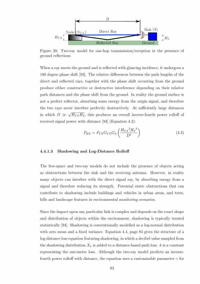
Figure 20: Two-ray model for one-hop transmission/reception in the presence ofground reflections
When a ray meets the ground and is reflected with glancing incidence, it undergoes a
180 degree phase shift [93]. The relative differences between the path lengths of the
direct and reflected rays, together with the phase shift occurring from the ground
produce either constructive or destructive interference depending on their relative
path distances and the phase shift from the ground. In reality the ground surface is
not a perfect reflector, absorbing some energy from the origin signal, and therefore
the two rays never interfere perfectly destructively. At sufficiently large distances
in which D �√HTXHS, this produces an overall inverse-fourth power rolloff of
received signal power with distance [93] (Equation 4.3):
PRX = PTXGTXGS
(HTX
2HS2
D4
)(4.3)
4.4.1.3 Shadowing and Log-Distance Rolloff
The free-space and two-ray models do not include the presence of objects acting
as obstructions between the sink and the receiving antenna. However, in reality
many objects can interfere with the direct signal ray, by absorbing energy from a
signal and therefore reducing its strength. Potential static obstructions that can
contribute to shadowing include buildings and vehicles in urban areas, and trees,
hills and landscape features in environmental monitoring scenarios.
Since the impact upon any particular link is complex and depends on the exact shape
and distribution of objects within the environment, shadowing is typically treated
statistically [94]. Shadowing is conventionally modelled as a log-normal distribution
with zero mean and a fixed variance. Equation 4.4, page 84 gives the structure of a
log-distance loss equation featuring shadowing, in which a decibel value sampled from
the shadowing distribution Xσ is added to a distance-based path loss. k is a constant
representing the one-metre loss. Although the two-ray model predicts an inverse-
fourth power rolloff with distance, the equation uses a customisable parameter γ for
83
rolloff rate. This allows the effect of the environment and any obstructions within it,
which may alter mean loss characteristics, to be accounted for. γ = 2 represents the
conventional inverse-square free space model, and γ = 4 represents the inverse-fourth
loss predicted by the two-ray model.
L(dB) = GTX +GS + k(dB) + 10γlog10d+Xσ (4.4)
In the next section, empirically sampled values for these parameters in typical
environments will be presented, supporting the extension of this model into two
discrete distance regions (a near-field and far-field) with distinct parameters and
characteristics.
4.4.2 Empirical Research On Propagation
Martinez-Sala et al. [95] performed empirical studies of the propagation losses for
WSN communication in three different physical environments. They discovered that
a two-slope log-distance loss model (separating the loss characteristics into near-
field and far-field regions) with shadowing provides a good model within flat plain,
urban, and outdoor park environments. The two-slope model is defined by the
following pair of equations. Equation 4.5, page 84 applies to all distances within
the transition region (breakpoint) and defines the near-field region behaviour, and
equation Equation 4.6, page 84, applies to distances greater than this and defines
the far-field.
L(d)(dB) = L01 + 10γ1log10d+Xσ0 if d < dr (4.5)
L(d)(dB) = L02 + 10γ2log10d+Xσ1 if d� dr (4.6)
Empirically measured parameters are provided in Table 1, and demonstrate the best
fit (smallest statistical variables) in outdoor and rural environments. These param-
eters indicate that the most uniform channels are found in physical environments
with the least environmental variation and without obvious obstruction.
It is notable that the breakpoint in Martinez-Sala’s two-slope model is particularly
close in all environments, particularly for sparsely deployed topologies. In the further
work in this physical-layer modelling, the far-field environment will be considered, as
this range is more realistic given the limited deployment densities in a sparse sensor
network deployment. Although shadowing is a statistical phenomenon, it is possible
84

Symbol Parameter Groundplain envi-ronment
Universityyard
Park
γ1 Near field exponent 2.34 2.76 2.09γ2 Far field exponent 3.73 4 4.01σ1 Near shadowing std.
dev.0.6 2.98 0.28
σ2 Far statistical std.dev.
0.42 1.82 0.67
dr Breakpoint (m) 6.2 3.2 0.95L01 One-metre intrinsic
near loss (dB)37.8 63.24 72.1
L02 One-metre intrinsicfar loss (dB)
26.79 44.5 41.9
Table 1: Parameters for the two-slope model for typical WSN channels in threeenvironments discovered in [95]
to model it by including a shadowing distribution via which a logarithmic normally-
distributed value is added to the loss output from the raw distance-based SINR
model. By adding a conservative amount to the overall SINR requirement in the
link budget, it is possible to develop a system which is resilient with high probability
against temporary link changes brought about from shadowing and fading.
In the thesis, the far-field region of this model will be employed to analyse the
communication properties of distributed beamforming (Section 4.5.2, page 89), for
computation of the link properties and assessment of the transmission success.
For short-range communication, given that the distance is shown to be the most
significant factor in connectivity, the protocol model can be employed, which
considers the closest interferers as significant.
4.4.3 The Protocol Model
The protocol model [33] is a simple model of connectivity which provides a static
distance-based model of propagation success. It can be represented as a pair of
graphs, the communication graph C and interference graph I defining communication
and interference relationships [96]. Nodes constitute the vertices of these graphs and
interactions between them, the edges.
Any nodes connected by an edge in C can communicate without interference, as
long as no node connected in I to the receiver is also transmitting simultaneously.
85

Assuming a planar network in which loss is distance-based, this model defines a
fixed connectivity range cr over which nodes can communicate, as long as no node
within the receiver’s interference range is transmitting concurrently. This situation
is referred to as a collision. The interference range is Ir = (1 + ∆)cr, and so is
larger than the connectivity range by an additional factor of ∆. Typically values
of ∆ assumed to be significant for collision avoidance are in the range of 1.0 to 2.0,
corresponding to significant interferers twice or three times further away from the
further communications peer.
Figure 21, page 86 illustrates the protocol model of connectivity. Nodes A and C
cannot ever communicate, since C is outside A’s connectivity range. A and B can
communicate, as long as any node in B’s interference range is silent. Here, if I is
transmitting to Z, A cannot simultaneously communicate with B under the protocol
model. In this diagram, Ir = 2cr, that is ∆ = 1.
Figure 21: The protocol model of connectivity
4.4.3.1 Protocol Model Validation
The intuition behind the protocol model is that transmissions from nodes outside of
the interference range can be disregarded, given the high log-distance loss exponent
assumed. For example, a node twice as far away as the furthest potential communica-
tion peer, under log-distance loss exponent γ = 4 experiences an additional distance-
based loss approximately 12dB greater than the peer. With homogeneous WSN
86

nodes transmitting with equal power, the contribution of sufficiently remote nodes
to interference (and therefore to collision events) is typically assumed insignificant.
This section analyses the physical-layer interference characteristics of transmissions
to determine whether obeying the protocol model constraints produces reliable
reception, using the empirically sampled model in Section 4.4.2, page 84.
Figure 22, page 88 presents a cumulative distribution function (CDF) of the signal-
to-interference (SIR) ratio for 10000 trials in simple one-hop transmission-reception
under the protocol model. A number of active interfering nodes are located
between two and three times further away from a central receiver than its associated
transmitter. This obeys the protocol model in the most permissive case of ∆ = 1,
in which the closest interferer permitted is twice as far as the transmitter. Physical
layer parameters are obtained from Martinez-Sala’s two-slope log-distance loss model
for the university environment (Table 1, 85), the most variable environment in which
the greatest impact from shadowing is anticipated.
The results in the CDF show that in the presence of a single active interferer, 99.9% of
test trials experienced a SIR greater than 3dB. In the presence of 3 active interferers
outside of the interference range, 98.9% of trials still succeeded. With 5 interferers
operating the figure is 96.6%. Therefore, only 3.4% of transmissions fail to deliver an
SIR of 3dB or greater under the protocol model assumptions of interferer location,
even in this rare case of local congestion. The presence of additional simultaneous
interferers within this close a range would be rare, given that such interferers would
require protocol model protection for their own transmissions.
This therefore validates the protocol model as a reasonable approximation to model
connectivity in realistic physical-layer scenarios. Within this thesis, activity within
the interference graphs will not be analysed as it is assumed that the MAC scheme
provides sufficient collision protection to prevent these contending transmissions.
The communication graph, and the range limits that generate it, will be analysed to
determine connectivity properties of multihop routing topologies.
4.5 Supernode Communication Architecture
4.5.1 Introduction
Having considered the characteristics of direct short range communication between
a single transmitter and receiver, this section explores an alternative communication
87

−10 0 10 20 30 40 50 600
0.5
1
Protocol model validation via SIR produced in the presence of multiple interferers
Signal to interference ratio (SIR)
Cu
mu
lative
dis
trib
utio
n
One interfererTwo interferersThree interferersFour interferersFive interferers
0 1 2 3 4 5 6 7 80
0.1
0.2
Protocol model validation via SIR produced in the presence of multiple interferers
Signal to interference ratio (SIR)
Cu
mu
lative
dis
trib
utio
n
One interfererTwo interferersThree interferersFour interferersFive interferers
Figure 22: Physical SIR in the presence of interferers conforming to the protocolmodel
methodology. This employs distributed beamforming from a geographically close
cluster of nodes (supernodes) in order to transport network data to the central sink.
There exist a number of clear potential advantages to the use of supernodes for data
delivery as compared to multihop routing:
Restriction of coordination and key management Although solutions for key
management across an entire WSN exist (as explored in Section 3.9, page 70),
key management is inherently easier and lower in overheads if it is highly
localised and the only long-range communication is with a single highly-
resourced, line-powered entity such as the sink.
Location concealment of sources In security-conscious environments an adver-
sary may desire to reveal the location of transmitting entities. The supernode
approach may be helpful to disguise a transmitting source from remote
interception by spreading the power density of participating entities. This
could potentially be useful to disguise the location of data originators in
scenarios assumed to be subject to sophisticated physical-layer monitoring,
such as military environments.
The relaying burden presented by multihop routing is removed The relay-
ing burden leads to a per-node reduction in capacity as multihop networks scale
88

[33] due to the requirement for nodes to collaboratively forward their traffic
over long distances. In particular, the greatest bottlenecks in a multihop WSN,
those closest to the sink relaying more data for other nodes, are removed or
relieved of some of their activity through this approach. Although there is the
necessity for coordination amongst the supernode entities, the burden upon
individual nodes is distributed more evenly. The complexity of coordination of
remote entities is placed upon the sink, which, given its access to line power
and directional antennas, is more capable of handling it.
4.5.2 Distributed Beamforming Fundamentals
In work upon the theory of random arrays it is established that the linear gain
of N transmitting antennas can be shown to be N , assuming perfect phase
synchronisation amongst the transmitting elements [97]. A recent survey [98] covers
current developments in beamforming, giving coordination approaches and options
for organising their mutual communication and phase synchronisation process. This
section introduces the supernodes as a fundamental communication primitive to be
used by higher layer services, and outlines their mechanisms of operation.
Since sensor networks are normally energy-constrained due to their reliance upon
limited batteries, it is vital to be aware of approaches which can improve performance
and deliver energy efficiency advantages. Beamforming technologies can provide com-
pelling improvements in energy efficiency [99]. Typical energy efficiency advantages
over routing protocols occur from the removal of the overheads brought about by
route formation protocols, together with the relaying burden during data delivery,
with the removal of a requirement for idle listening, reception and retransmission
at intermediate hops. Although a beamforming transmission may require many
nodes making a simultaneous transmission, the transmitting group are typically
spatially close and thus easily coordinated, thus reducing the energy impact of their
transmissions.
As with any distributed systems technique, beamforming is dependent upon close
cooperation between the participating nodes. A coordination process is presented
[100] through which a pair of beamforming nodes can establish timeslots for
transmission, with the aid of a central coordinator. Since the beamforming process
is dependent upon close cooperation and tight time synchronisation between nodes,
89

it is important to establish its robustness to timing or phase synchronisation errors.
Deng et al [101] provide a performance analysis of the error tolerance of distributed
beamforming technologies, and concludes that RMS phase errors within 0.5 radians
lead to less than 3dB degradation of the peak beamforming gain in 95% of cases.
Therefore, as long as the coordination protocol can deliver this approach, then
supernode performance should be within a 3dB limit of the intended value.
4.5.3 Beamforming Architecture
In the beamforming approach considered in this thesis, collaborative transmissions
are made from a cluster of geographically close nodes (a supernode) to relay
information directly to the sink node in a single hop. Supernodes were proposed
for location concealment of sources as part of a Ministry of Defence Competition
of Ideas project conducted in the Communications Group of the Department of
Electronics in York [43].
Using dynamically formed beamforming clusters to perform a long-range relaying
task is implicitly difficult to place within the standard layer model. Essentially,
long-range physical links are dynamically formed from lower-layer interactions,
solving problems that would normally be solved at the routing layer through a
combination of physical-layer and media access techniques requiring small-scale time
synchronisation. A local collaboration is required to form supernodes, but multihop
routing is only required for an initial flood to inform the sink of their identity.
The model assumes a cluster of beamforming nodes, the supernode members (SNMs)
closely distributed around a coordinator (Figure 23), which assists the nearby nodes
to perform beamforming. This single cluster is termed a supernode, and those that
participate in its collaborative transmissions, including its coordinator, the supernode
normal members (SNMs). These supernodes transmit to a sink employing directional
antennas, and are organised by a network-wide media access scheme so as not to
interfere with each other, as described in Section 4.5.4, page 92. The following
section presents an architecture for transmission from the supernode to the sink
node is arranged via the following stages:
90

(a) Stage S0 - Supernode ManagementBy Sink
(b) Stage S1 - Dissemination of Data
(c) Stage S2 - Phase Adjustment (d) Stage S3 - Supernode Transmissionand Sink Reception
Figure 23: The supernode and the phases of data transmission using distributedbeamforming to relay information
4.5.3.1 S0 - Supernode Management By Sink
During stage S0 (Figure 23a), a periodic transmission is made to carry control
information to a supernode coordinator. For example, performance statistics such as
the SINR delivered by previous transmissions from this supernode are periodically
updated. It will act as a master time coordinator, informing the supernode
coordinator of any timing constraints affecting its transmission, and give timing
at which phases S2 and S3 must be performed.
4.5.3.2 S1 - Dissemination of Data
During stage S1 (Figure 23b), data for transmission is sent from the data originator
to the coordinator. The coordinator disseminates this transmission to all SNMs.
Here it is assumed that all originating nodes are within range of a supernode,
or can form a multihop route to reach one (via mechanisms explored in Chapter
7). This transmission may be unicast, but it is anticipated to be broadcast from
the coordinator since it distributes identical data to all surrounding nodes. An
acknowledgement from the nodes to the coordinator is expected, and retransmissions
may be performed if the nodes do not correctly receive the data.
91

4.5.3.3 S2 - Phase Adjustment
During stage S2 (Figure 23c), phase adjustment is made to allow the beamforming
transmission to occur successfully. Phase adjustment is assumed to follow a master-
slave architecture [100] [102] [103]. In this process the sink transmits a known
frequency reference carrier, which is compared with a carrier broadcast from the
coordinator to the supernode members. Through measurement of the relative timing
offset, the coordinator can determine an appropriate phase offset for transmission.
It is expected that this phase will occur less than 100 milliseconds before stage 3.
4.5.3.4 S3 - Supernode Transmission and Sink Reception
During stage S3 (Figure 23d), the supernode member nodes (SNMs) perform their
transmission, using the synchronisation information established. A known preamble
is added to the data to allow the sink to synchronise upon the beamformed data
and determine its start, compensating for any delay introduced by the channel. The
previous stage S2 is used to determine the phase offset to apply to transmission. It
is anticipated that this stage will occur less than 100 milliseconds after phase S2, to
minimise oscillator drift in the meantime and meet the criterion in Section 4.5.2, page
89, for signals arriving at the sink with sufficient phase synchronisation to obtain the
beamforming gains.
During this stage, the sink begins reception of the beamformed data. The phase
offsets established allow the transmitted signals to arrive constructively, increasing
their SINR and permitting the sink to receive the data. The SINR for reception is
measured and used to update statistics for the supernode, which are delivered back
to in the next S0 phase.
4.5.4 Supernode Formation and Media Access
It is possible to form supernodes either statically or dynamically. Static formation
refers to nodes being preassigned with identities as supernode coordinators or
members, with the attendant disadvantages of requiring manual involvement and
configuration of nodes before deployment. This requires the same type of manual
92
configuration of a relaying backbone as discussed in Section 2.2.1, page 36. It would
be desirable if supernode formation could be dynamic, to permit self-organisation.
In order to form supernodes dynamically, it is necessary for nodes to discover their
local neighbourhood, to avoid the problem of too many supernodes forming. A
node which wishes to join a supernode first waits to see if any supernode formation
broadcasts are received within a randomly selected time interval. If none are received,
it begins formation as a coordinator with a restricted flood, which serves to both
suppress supernode formation at nodes receiving it, and update a gradient pointer
giving the location of the supernode to other nodes that may wish to reach it
via multihop routing. This process effectively partitions the network regions into
supernodes, in a similar manner to the cluster head selection of LEACH [104].
Newly formed supernodes then make a one-off multihop routing flood in order to
inform the sink of their identity and node membership. The address assigned to a
supernode is determined by the identity of its coordinator. Upon this the coordinator
directs all nodes in the supernode to listen continuously, in anticipation of their
first coordination broadcast for stage S0. The sink, upon receiving this broadcast,
maintains a timing schedule for the supernodes in order to divide network capacity
between them. Since this information is held centrally, it is easy to make a fair
division of network capacity across all supernodes. Supernodes which do not reply
for a fixed interval are removed from the allocation. Depending on hardware available
at the sink, as discussed in Section 4.5.5.2, page 94, it may be possible to use space-
division multiplexing in order to share capacity amongst the nodes.
4.5.5 Hardware Aspects of Supernode Communication
4.5.5.1 Node Oscillators
It was noted that delay between stage S2 and S3 must be limited in order to
minimise oscillator drift between the different stages and a consequent reduction
in beamforming gain. In order to improve flexibility of this aspect, low-phase noise
oscillators may be helpful [22]. It is expected that as WSN technology matures,
low-phase noise oscillators will allow phase synchronisation to be held over longer
time periods.
93

4.5.5.2 Requirements For The Sink
Two possibilities present themselves for sink antenna management for the reception
in the phase S3 above. The simplest possible option would be an omnidirectional
antenna, in which all gain is delivered by the supernode beamforming process.
The advantage of this is the lowest implementation costs and complexity due to
its simplicity, with no requirement for antenna alignment or multiple antennas to
receive simultaneously from a variety of nodes. The disadvantage is the reduction in
capacity involved, since only a single supernode can be transmitting simultaneously
throughout the network. This would represent a more significant capacity bottleneck
than the use of conventional bottlenecks around the sink in multihop routing.
A more productive alternative is to apply a set of highly directional antennas to divide
the network into angular sectors, as in the sectorisation approach in a cellular system.
The advantage of the directional antenna approach is to increase capacity by allowing
spatial reuse, through providing rejection of interference from other supernodes in
other sectors of the network.
4.6 Hybrid Approaches
4.6.1 Routing To Reach Supernodes
It is possible to employ multihop routing in order to reach a supernode. The
advantages of doing so include a reduction in the requirement for every node
to be within range of a coordinator, which allows supernodes to be formed
opportunistically. This allows for more flexible integration of supernodes into a
network.
The flexibility of this strategy lies in its implicit fallback and failure tolerance, in
that if a supernode cannot be reached, it is always possible for nodes to form a
multihop route directly to the sink as in the conventional case. By providing a
variety of transmission methodologies, nodes have more options for finding a viable
transmission methodology in the presence of diverse attacks. Chapter 7 presents
a routing algorithm, physical reputation-based routing (PRBR) that finds routes
through high-performance supernodes.
94

Figure 24: A hybrid supernode relaying strategy in which nodes relay their datathrough at least one other supernode before it reaches the sink
4.6.2 Hybrid Routing To Supernodes
It is also possible to perform transmissions from a supernode for reception at an
intermediate relaying supernode, for further retransmission. In this approach, the
destination of the beamforming transmission of the first-stage supernode would itself
be a supernode. This is illustrated in Figure 24, page 95. This would provide much
greater diversity through the number of possible independent channels generated,
and therefore resilience against fading of any individual link between a single sender
and receiver. However, the complexity of these algorithms is likely to increase
unacceptably, together with problems at a system integration perspective.
There are several problems that limit the applicability of this approach. Supernodes
are implicitly distributed and thus disparate entities. Since their presence is
transitory, it would be difficult to devise a practical and scalable scheme to
communicate between them their initial locations for route formation. Also, the
use of directional antenna transmission in order to initially coordinate supernodes
(i.e. to inform their presence and parameters) would be difficult without the presence
of some single heterogeneous device, the sink which can serve to organise their initial
communication. As a result, the supernode cases considered in this thesis all use the
sink as an endpoint and not another supernode.
95

4.7 Topologies and Network Scenarios
This section will present three standardised models for node placement which are
used in various models throughout the thesis. In order to provide a fair comparison
between networking methodologies, it is important that the network topologies which
are studied are sufficiently well-connected to allow all nodes to be reachable from
the sink. For example, a topology in which the sink was not reachable from some
nodes would be excessively vulnerable to a wormhole attack, and inherently unable
to implement wormhole avoidance as the wormhole would be required in order to
connect the topology. Therefore, this section analyses the connectivity behaviour of
various topologies.
4.8 Topology Models
In some scenarios, it is possible to control the physical placement of nodes very
precisely. This is referred to as deterministic coverage [105]. In networks in which
nodes will be deployed manually in unobstructed terrain, deterministic coverage may
be viable. However, this approach does not capture the impact of variability in
placement, which may arise from physical obstructions in the deployment region,
vulnerabilities in physical security limiting activity, or the inherent variability
resulting from large-scale placement of devices such as aerial scattering of nodes.
This leads to stochastic coverage [106], in which the placement of nodes is not fully
deterministic, but incorporates variability.
Three topology placements are used throughout the thesis. If the sink can be
centrally placed, a radial ring arrangement can be employed, with nodes upon each
ring at a progressively greater distance from the central sink. However, this approach
does not capture the impact of variability in placement, which may arise from
physical obstructions in terrain, or automated placement such as aerial scattering
of nodes. Accordingly, this thesis incorporates other topology models which serve to
represent a realistic range of coverage strategies. These are the uniform random and
grid-based Gaussian variation models.
If connectivity is sufficiently deterministic and follows the protocol model, it is
possible to extrapolate local connectivity properties to the whole network. This
96
Radial ring separation distance sArc length per node in ring r krNumber of rings Rmax
Table 2: Parameters for the radial ring topology
can be done by considering the network itself a graph with each link as a vertex,
determining from the behaviour of individual links whether nodes are reachable via
any path within the topology. Computing the transitive closure upon this network
graph starting from the sink, and measuring the number of nodes included, is able
to determine whether nodes are reachable from the sink. Connectivity properties are
therefore important since they set constraints on the number of devices that must
be deployed to engineer a stable network.
As shall be investigated in Section 4.8.2, page 99, the connectivity of a network
strongly depends on the density of nodes deployed, or upon their communication
ranges relative to separation distance. Once a sufficiently large number of nodes is
deployed, a multihop routing network suddenly passes the point of being disconnected
islands and a high proportion of nodes become reachable from the sink. This is called
the network connectivity phase transition [107]. Therefore, studying connectivity is
able to predict whether a network will be sufficiently robust to fulfill its intended
application goals, even without the presence of malicious attack.
4.8.1 Radial Ring Based
The radial ring topology consists of a single central sink node, surrounded by nodes
arranged in concentric circles. It is assumed that the sink node possesses an out-of-
band channel, or wired link allowing it to relay its information out of the sink. This
topology structure is entirely deterministic, in that the location of each node can be
determined precisely.
An advantage of the radial-ring topology is that by arranging the sink node to
lie at the centre of concentric circles, routes from a particular distance away from
the sink all have consistent hop lengths. The connectivity of the topology can be
easily determined, and as will be be demonstrated, is highly consistent. The radial-
ring based topology is structured according to the parameters in Table 2. The
circumference of ring index r is 2πsr, and if Nr nodes are placed around it, each
with an equal angular separation θr, then NrΘr = 2π.
97

−700−500−300−100 100 300 500 700−700−600−500−400−300−200−100
0100200300400500600700
Connectivity of nodes in the radial ring topology, k/s = 0.52
X Position (m)
Y P
ositio
n (
m)
(a) Topology structure
0 50 100 150 200 2500
0.2
0.4
0.6
0.8
1
Range limit distance (m)
Pro
po
rtio
n o
f n
od
es
re
ach
ab
le f
rom
th
e s
ink
Sink reachability of nodes in the radial ring topology, k=0.52, s = 100m
(b) Proportion of nodes reachable fromthe sink
Figure 25: The radial ring topology and its connectivity (sink reachability)
In order to maintain connectivity between adjacent nodes in all radial rings, the arc-
length is equalised across all radial rings, so for all r: ∀r.kr = k. The integer number
of nodes that can be placed around this ring, producing an arc-length between them
of less than kr, is:
Nr =
⌊2πsr
k
⌋Therefore the corresponding θr:
Θr =2π
Nr
=2π
b2πsrkc
(4.7)
Therefore, in ring r there exist Nr nodes, {Nr,0, Nr,1 . . . Nr,Nr−1}. The location of
node index n in ring r in polar coordinates (Rr,n, θr,n), is defined by Equation 4.9.
Rr,n = rs (4.8)
θr,n = Θr(n− 1)
Nr
(4.9)
A sample of the radial ring topology is presented in Figure 25, page 98, for parameter
values k = 0.52 and s = 100m. The connectivity of the topology is analysed using
a transitive closure algorithm. The transitive closure is found by starting at the
sink, finding all nodes reachable from it, and iterating until all nodes connected to a
reachable node are found. All nodes within the transitive closure of the sink will be
able to find a viable route from the sink.
98

Figure 25b, page 98 illustrates the proportion of network nodes reachable from the
sink. The reachability shows a very clear transition around the ring separation s.
This is as expected, illustrating that the topology is highly regular. This topology
will be used in Section 4.9, page 101 in the analysis of the performance of supernode
and multihop relaying.
It is notable from the link structure depicted that some irregularities exist in which
nodes are connected to adjacent peers in surrounding rings offset at an angle, while
others are disconnected. Although the topology structure attempts to attain a
consistent spacing around all radial rings, the restriction to an integer number of
nodes within any ring makes this unattainable in all cases, which leads to situations
in which some nodes have different peer counts dependant on their positions around
the ring. Therefore, some nodes have better connectivity to the inner and other rings
than others.
4.8.2 Uniform Random
The uniform random topology features entirely stochastic placement [106], in which
both axes of the nodes Cartesian coordinates are uniformly distributed across the
topology region, a square of side S centred upon the origin. This may correspond,
for example, to aerial deployments from high altitude, or the results of initially
mobile nodes settling e.g. following mobility or drifting, or others with no a priori
information about node placement other than a uniform density across the topology.
The coordinates of uniformly randomly distributed node Ni, (UXi, UYi) are defined
as the result of drawing two independent samples from a pair of uniform distributions
spanning axes along side of the deployment region.
One realisation of the uniform random topology is illustrated in Figure 26, page 100,
showing a phase transition change in the connectivity pattern for a deployment of
100 nodes. In Figure 26a, page 100 the range cutoff for communication DMAX = 56m
limits the nodes to disparate islands, but in Figure 26b, page 100, with DMAX =
110m the topology is now fully connected. The sink reachability of the nodes is
presented in Figure 26c, page 100. Compared to the radial ring model, the uniform
random topology model shows a gradual increase in sink reachability with maximum
communications range, as the link lengths involved are more variable. It is notable
that the link length that connects the topology fully with some redundancy is
99

−200 −100 0 100 200
−200
−100
0
100
200
Connectivity for a uniform random topology
X Position (m)
Y P
ositio
n (
m)
(a) Disparate islands of connectivity
−200 −100 0 100 200
−200
−100
0
100
200
Connectivity for a uniform random topology
X Position (m)
Y P
ositio
n (
m)
(b) Fully connected topology
0 20 40 60 80 100 120 140 160 1800
0.10.20.30.40.50.60.70.80.9
1
Range limit distance (m)
Pro
po
rtio
n o
f n
od
es
rea
cha
ble
fro
m s
ink
Sink reachability of nodes in uniform random topology
(c) Proportion of nodes reachable from the sink
Figure 26: The uniform random topology and its connectivity (sink reachability)
approximately double the connectivity of the mean link length (for this realisation
60m).
4.8.2.1 Grid-Based With Gaussian Variation
A grid topology consists of nodes placed precisely upon a regular grid. This is a
standard topology model, the intuition behind which is to make sure that phenomena
are covered by a subset of multiple sensors [108]. It also helps to ensure topology
connectivity by giving each node a fixed number of neighbours, so if some links are
broken due to link variability such as shadowing or slow fading, then the node is still
reachable from other peers. The grid-based Gaussian variation topology (Figure 27,
100

−500 0 500−600
−400
−200
0
200
400
600
Connectivity for a grid−based Gaussian topology
X Position (m)
Y P
osi
tion (
m)
(a) Fully connected topology
0 200 4000
0.2
0.4
0.6
0.8
1
Range limit distance (m)
Pro
po
rtio
n o
f n
od
es
re
ach
ab
le f
rom
th
e s
ink
Sink reachability of nodes in grid−based Gaussian topology
Rf=0.9
(b) Proportion of nodes reachable fromthe sink
Figure 27: The grid-based Gaussian topology and its connectivity (sink reachability)
page 101) model incorporates an element of stochastic variation in coverage into the
grid-based topology. It occurs in a square topology of side S, and the basis grid has a
separation distance DP between nodes on one axis. Define the integer nodes on side
SN , where total node count N = SN2. Peer distance can be defined as DP = S
SN−1.
G(µ, σ2) defines sampling a Gaussian distributed random variable with mean µ and
standard deviation σ.
Equation 4.11, page 101 defines the Cartesian coordinates of node Ni, (NX , NY )
under the grid-based Gaussian model. The regularity factor defines the regularity of
the topology, by controlling the variance of the Gaussian variation around the grid
positioning. The special case Rf = 1 corresponds to a purely grid-based topology.
NX = DP
(imodSN −
SN − 1
2+ G(0, (1−Rf )
2)
)(4.10)
NY = DP
(b(i/SNc)−
SN − 1
2+ G(0, (1−Rf )
2)
)
4.9 Signal Jamming Impact Upon Data Delivery
4.9.1 Introduction
The previous models for transmission success have been developed for networks in
which all nodes are operating in accordance with their expected behaviour. However,
101
if malicious nodes exist which are are failing to fulfill their obligations under the
protocol, it is likely that failure rates for end-to-end routing will be considerably
higher. This section explores the success rates of multihop routing and beamforming
in the presence of signal jamming attacks.
A signal jamming attack is one of the easiest attacks for an adversary to deploy
in a WSN. Jamming is a particularly low-effort attack since the only equipment
required is a transceiver capable of generating a null carrier or interference, which is
conceptually simple and easily deployed. Furthermore, given the power limitations
assumed upon sensor nodes, it is possible for jamming attacks to radiate considerably
more power than any individual transceiver. Since the attacker may be deploying
only a small number of devices, economics favour the attacker, in that it is possible for
them to have transmitters capable of radiating greater power, and more interference,
than a typical wireless sensor network node.
This section analyses the impact of signal jamming attacks upon the data delivery
mechanisms in a WSN, explaining fundamental assumptions, providing a model of
the performance of both multihop routing and distributed beamforming relaying
mechanisms under interference. It then provides simulation results to demonstrate
their performance, and discusses the conclusions obtained.
4.9.2 Scenario and Modelling Assumptions
The model assumes the fully deterministic radial topology Section 4.8.1, page 97.
This is located within a circular region of radius R = 800m with a central sink. An
advantage of a deterministic topology such as this is that when no attack is present
in the network, the supernode can always be formed, there are no failure modes due
to insufficient supernode membership to transmit the necessary data. It is assumed
that an out-of-band channel or wired link serves to transport data from the sink out
of the network, and therefore no additional interference is contributed.
The radial rings in which the nodes are arranged are spaced DP = 100m apart. In
specific tests JC jammers are distributed uniformly throughout the topology. Data
sources (and supernode coordinators) are located on the outer ring of the topology at
radial distance DS = 600m. The log-distance loss exponent γ = 4.01 is assumed in
102

this propagation environment, as corresponding to the far-field region of Martinez-
Sala’s empirical propagation model (Table 1, 85).
The scenario explored in this section is that all jammers considered in this work are
equipower jammers, considered to radiate power equal to a standard network node.
This case of attack is suitable to consider for attacks implemented by compromised
nodes, in which malicious nodes are assumed to have all the the public decryption
keys available to the node but not able to impersonate the sink due to the lack of
resources. The jammers are assumed to be intermittent jammers, which do not block
routing packets but instead block data delivery. This improves the stealth delivered
by their attack and prevents the protocols from routing around them.
Regarding reception at the sink, it is assumed phase synchronisation using a
local coordinator and the sink immediately before beamforming achieves negligible
synchronisation error given the oscillators available. It is assumed that the sink’s
reception antenna is physically steerable, aligning towards the supernode during
reception with high directivity, with a beamwidth Bθ radians that spans twice the
radius of the supernode cluster, and that sidelobes are not significant for interference
collection.
4.9.3 Multihop Routing
Jammers transmit with the same power as a node. Assuming a transmitter in the
routing chain is spaced at DP from a receiver, and the closest jammer is DJ from
the receiver, the requirement for minimal reception at SIR = SIRmin is:
DP−γ
DJ−γ = SIRmin (4.11)
The circle around the receiver at radius DJ is the vulnerable area per multihop node
VM = πDJ2. Rearranging Equation 4.11 for DJ gives VM :
VM = πDP2(SIRmin)2/γ (4.12)
Without loss of generality, assume nodes lie in a straight line. Since these vulnerable
areas partially intersect under typical parameters, total route vulnerable area VR on a
route of RL nodes can be approximated using the cylinder and end semicircles (shown
in Figure 28, page 104) containing them. This applies regardless of the relative angle
between two nodes in the forwarding chain, since due to rotational symmetry, if two
103

Figure 28: Modelling multihop routing vulnerable area as a cylinder and attachedsemicircles
circles are offset from one another, then the overlap area is constant regardless of
the angles involved.
VR ≈ π(DPSIRmin
1/γ)2
+ 2(RL − 1)(DP
2SIRmin1/γ)
(4.13)
If a jammer lies within the vulnerable area VR, data delivery will fail. Therefore the
probability of successful delivery via multihop routing PMR can be approximated
from a binomial term giving the probability that none of JC jammers are located
within the vulnerable proportion of the overall topology:
PMR ≈(
1− VRπR2
)JC(4.14)
4.9.4 Supernodes
Using supernodes, two steps in the data delivery protocol are vulnerable to
jamming; the hop-by-hop data distribution and synchronisation phase, and then
the beamforming transmission back to the sink.
Any adjacent nodes within the cluster must be able to mutually communicate in
order to synchronise their clocks and any phase offsets, and exchange data for
the transmission. We assume that all nodes for the supernode lie in a single hop
communication range of each other at range DP . Therefore, the vulnerable area
VSNODE is entirely localised around the supernode coordinator, and is the same as
the single node multihop case in Equation 4.12:
VSNODE = πDP2(SIRmin)2/γ (4.15)
104
For correct data delivery, the sink must also receive successfully, which requires the
incoming signal to be above the SIR threshold. The use of a directional antenna
gives a vulnerable area as a truncated sector (reduced radius) of the topology. At
the axis of the antenna alignment, the receiving antenna amplifies both the signal
and jamming interference equally, so the outer radius of this partial sector RSLICE
can be derived from the supernode linear gain GS and distance from the sink to the
supernode centre DS as:
RSLICE = DS
(SIRmin
GS
)1/γ
(4.16)
Therefore, the area of the vulnerable partial sector VSINK is determined from the
receiving antenna beamwidth Bθ as a proportion of the area of the circle with radius
RSLICE:
VSINK =Bθ
2RSLICE
2 (4.17)
The final supernode success probability PSN is obtained using the binomial distribu-
tion, assuming none of JC jammers are located in either VSNODE or VSINK :
PSN =
(1− VSNODE + VSINK
πR2
)JC(4.18)
4.9.5 Simulation Methodology
The simulation is implemented using a simulator in the OCaml language [92]. To
begin a simulation run, a radial ring test topology is generated, with sources at
600m radial distance from the sink. A gradient based routing algorithm is executed
to construct the shortest path routes to the base station. Within this topology,
JC jammers are generated, uniformly distributed. An ensemble of topologies is
considered, incorporating variation in jammer placement.
To simulate multihop routing, routes are tested hop-by-hop in sequence from the
source to their final destination at the sink. Jamming linear interference power
from all jammers at the receiver’s location is computed and summed. The received
SIR is computed determine whether the transmission to the receiver of each hop
could overcome the aggregate jamming interference. If any hop fails to meet
the interference constraint, the routing request is considered subject to jamming
interference, and recorded as such in the statistics.
105

For simulation of supernode delivery, a cluster of N = 4 nodes is considered, with
each data source the coordinator of the data. This represents a pure beamforming
scenario with no multihop routing involvement. Firstly, transmission for the data
dissemination phase S1 is tested, by testing SIR over aggregate jamming interference
from the coordinator to member nodes. Then the reverse direction (sink to candidate
member) is tested in the same manner. Bidirectional communication must succeed
for a minimum of N nodes for the S1 phase to be considered free of jamming.
Then phase S3 is modelled, testing SIR upon reception at the sink with the supernode
gain applied. If the SIR meets the constraint, then this phase succeeds also. If both
phases S1 and S3 succeed, then the delivery of this packet is considered a success.
4.9.6 Simulation Validation
This section considers the validation of the simulation against the analytic model.
Although validation of the complete scenario is implicit in the close match between
simulation and analytic results presented in the full scenario results (Section 4.9.7,
page 109), validation tests employing simplified scenarios will be presented to
demonstrate the conformance more clearly. In particular, activating only one single
jammer per simulation, and plotting the jammer locations which lead to data delivery
success allows the shape of vulnerable areas to be defined, validating the output of
the simulations against the analytically predicted values.
4.9.6.1 Single-Source Multihop Routing Validation Against Analysis
In order to perform this validation test, a special case of the deployment scenario was
considered. In these validation tests, a single source is activated, with a single jammer
present within each topology. The intent of this is to establish the geometric regions
of vulnerability to a specific jammer, via repeated trials of jammer deployment at
different locations. Consider a single multihop routing chain, as depicted in Figure
29, page 107. The active source S is located at the end of this chain, and the sink
at (0, 0) is the destination of the routing requests. Areas surrounding intermediate
receivers which are vulnerable to jamming are indicated by the circles.
Within a series of validation simulations, a single jammer is uniformly distributed
within a circular region of radius 700m. The validation test proceeds by computing
106

−200 0 200 400 600 800
−300
−200
−100
0
100
200
300
S
X Position (m)
Y P
ositio
n (
m)
The single multihop route used for simulation validation
Figure 29: A simple multihop routing chain used in simulation validation
hop-by-hop the physical SIR at all intermediate receivers, taking interference from
the jammer into account. Success is reported if the multihop transmission was
able to reach the sink without jamming at any stage. The proportion of successful
transmissions can be contrasted with the analytical prediction for vulnerable area
(Equation 4.13, page 104. Since the jammers are uniformly distributed, the
vulnerable area can be estimated from the proportion of simulation cases that fail,
and the non-vulnerable area to jamming, 1 − VA, can be estimated from the cases
that succeed.
Figure 30, page 108 illustrates the conformance between simulation and analysis
for the single-source multihop routing chain, for SIRmin = 0dB. The circles and
rectangle define the analytically predicted vulnerability regions for these parameter
values. The dots define simulation trials in which the jammer location did not prevent
successful delivery. In total 100000 trials of jammer placement were conducted.
It can be seen that the only locations in which the simulation did not conform to
the analytically predicted vulnerable area VR is in the areas between the circles at
the edges of the tubes, in which the tube model of Equation 4.13, page 104 assumes
a failure. The simulation however respects the vulnerability circles surrounding each
individual receiver, as illustrated in Figure 29, page 107. The proportion of topology
vulnerable area is computed analytically as 0.915, and the proportion of simulation
trials that succeed is 0.916.
107

Figure 30: Simulation trials of multihop relaying in the presence of a single jammer
4.9.6.2 Single-Source Supernode Validation Against Analysis
In this section the validation methodology of the previous section is applied to
supernode data delivery. A single jamming model is investigated in which a single
source is activated at (600, 0). This source acts as a supernode coordinator and
recruits other nodes to participate in distributed beamforming. The simulation
models the success of this process both in finding the required number of members
free of jamming to participate, and secondly in a successful jamming transmission
to the sink free of interference.
The analytic supernode model predicts the existence of two vulnerable regions, firstly
a circle located around the supernode coordinator, and secondly a sector around the
sink reception antenna. Figure 31, page 109 shows the structure of this in the case
of SIRmin = 0, in which the areas are disjoint. The figure clearly illustrates in the
simulation trials the presence of a circle of vulnerable area around the coordinator,
which under these parameters has the predicted radius of DP = 100m. The
sector around the sink is aligned towards the sink and with the predicted half-
beamwidth of 18 degrees specified in the simulation parameters, and maximum
DSLICE = G−1/γS = 600√
2. The analysis predicts a vulnerable area of 0.942 while
the proportion of simulation trials successful is 0.941.
108

Figure 31: Simulation trials of supernode data delivery in the presence of a singlejammer
4.9.7 Results
Figure 32, page 110 contrasts simulation results with the analytic models for multihop
and supernode reception shown in PMR (Equation 4.14) and PSN (Equation 4.18)
respectively.
The first purpose of these results is to demonstrate the close agreement between the
analytic models and simulation for both multihop and supernode delivery. Especially
with smaller number of jammers JC < 10, the agreement is extremely close. When
the number of jammers increases, the analytic model is further from the simulated
result. This results from simulations which feature aggregate interference from all
jammers in the network, in contrast to the analytic model which features only
interference for a single jammer. It is notable that a closer match between simulation
and analysis is exhibited for multihop routing compared to supernode delivery. For
multihop routing, the absolute error in delivery proportion is less than 3% of data
generated, although for multihop delivery the analytic model over-estimates delivery
success by around 5%. This can be explained by the assumption that only a single
jammer is significant in construction of the model. This assumption is likely to hold
when jammers are located close to receivers, but given the greater distances in sector
vulnerable area in the supernode model, the additional interference terms from other
jammers are likely to be more significant.
109

0 5 10 15 20 25 300
0.1
0.2
0.3
0.4
0.5
0.6
0.7
0.8
0.9
1Success proportion for multihop routing versus supernode under jamming
Jammer count (JC)
Pro
port
ion o
f data
deliv
ery
successfu
lly
Simulated multihop resultsAnalytic multihop model P
MR
Simulated supernode resultsAnalytical supernode model P
SN
Figure 32: Results showing improved performance of the supernode approach versusmultihop routing
Contrasting the supernode delivery scenario with multihop routing, both simulation
and analysis indicate that the supernode approach provides significantly better
performance under heavy jamming. For JC < 10, it is possible to delivery
approximately twice as much data successfully without jamming incidents using
supernodes as opposed to multihop routing. For JC = 30 approximately six or seven
times as much data can be delivered without jamming using supernodes as opposed to
multihop routing. A key factor in the vulnerability of multihop routing concerns the
geographical distribution of its vulnerable areas throughout the radial ring topology,
explored in Section 4.9.6, page 106. Multihop routing must communicate its data
hop-by-hop towards the sink, in which the inner ring of relaying nodes is vulnerable
to jamming. The placement of a single jammer sufficiently close enough can disable
any multihop routes using this node as a forwarder, which is extremely likely to
happen when a large number of jammers are introduced. However, by contrast with
supernode delivery, jammers close to a source only disable it from participating as
a supernode coordinator. For example, if a single jammer is close enough to be
disruptive to some potential supernode members on one side of the coordinator, the
coordinator is likely to be able to compensate by recruiting other members upon the
other side of its communication range, far enough from the jammer to communicate
successfully. This limits the impact of jamming upon the collaboration phase of the
110

beamforming process.
In terms of vulnerability to failure and jamming tolerance, the result graph illustrates
that supernode routing has considerably better jamming tolerance. Supernode
jamming can tolerate in excess of 20 jammers network-wide before exhibiting delivery
proportion of less than 0.4. By contrast, the multihop network reaches a delivery
proportion less than 0.4 with only 9 jammers present. Again, the reduced tolerance
of multihop routing in comparison to supernode delivery can be explained due to the
presence of the single point of failure in the region of the sink in multihop routing,
in which a single jammer can hamper delivery for a large proportion of the network.
4.10 Conclusion
This chapter has explored methodologies to implement practical WSN systems,
and motivated simulation as important for the development of new network
protocols, resulting from the high costs of deployments and the need for a consistent
environment for testing. It has then explored the models of radio communication
that will be presented throughout the thesis in order to perform comparisons of
different data transmission methodologies.
The distributed beamforming transmission has been introduced and an architecture
provided for coordinating transmission to the sink from supernodes. Finally,
standard topologies have been specified and their connectivity properties analysed.
An analysis has been made as to the impact of jamming interference upon multihop
routing versus distributed beamforming, showing that the distributed beamforming
approach provides superior jamming resistance. The following chapter will consider
a particular security attack in sensor networks, the wormhole attack, applying novel
routing metrics to avoidance of the wormhole attack.
111

Chapter 5
Wormhole Avoidance UsingDisturbance Based Routing
5.1 Introduction
This Chapter presents and analyses routing metrics that can defend against subtle
topology distortion attacks such as the wormhole attack (Section 3.5, page 56). This
attack is important in that it cannot be countered directly by cryptographic means.
The distortion of the topology provides control to the attacker, through a long-
distance link which they can temporarily or permanently disrupt. Therefore, it is
important (in addition to other security mechanisms) to prevent routes from using
the wormhole if possible.
This chapter presents a multihop routing technique, disturbance-based routing,
which uses custom metrics to defend against the wormhole attack by routing
preferentially around wormholes. Through this approach, characteristics introduced
by the wormhole, either in static connectivity of the topology, or during operation,
allow it to be detected and penalised. This reduces the probability of multihop routes
using the wormhole link. Through this approach the control which the attacker can
gain, and therefore their capacity to disrupt network operation, is greatly reduced.
The approach is entirely distributed, and builds upon a well-established protocol
for Ad-Hoc On-Demand Distance Vector (AODV) routing [109]. Unlike the other
techniques covered in Section 3.5, page 56, the disturbance-based routing approaches
do not depend on details of timing, consume excessive system resources, or otherwise
exhibit prohibitive computational complexity.
112

5.2 Analysis Of Wormhole Threat
As covered in Section 2.2.1, page 36, the deployment of heterogeneous entities, such
as long-distance backhaul relaying links, is often used to enhance performance in
real sensor network deployments, through the significant advantages it offers in
maintaining connectivity across sparse regions. Therefore, an attacker introducing
their own heterogeneous entities with greater capabilities such as a long-range out-
of-band channel linking a pair of entities, will obtain an equivalent gain in resources
and therefore a significant advantage. This section extends the consideration of the
wormhole in the literature in Section 3.5, page 56, and develops a distinction between
types of wormhole attack in regard to the level of intelligence and packet inspection
exhibited.
5.2.1 Passive Wormhole Case
In the simplest wormhole case (the passive case) a malicious attacker deploys one or
more pairs of energy-rich external devices that utilise a private low-latency channel
(assumed out of band so as not be visible as an interferer) between the paired
endpoints. An operating wormhole of this type is illustrated in Figure 33, page
114. Each wormhole endpoint listens to the channel in promiscuous mode and
intercepts any packets heard locally, tunnels them across the private channel to
the other wormhole endpoint, and rebroadcasts them at this remote endpoint. The
passive wormhole merely intercepts all transmissions on a detected frequency and
rebroadcasts them without any knowledge of their contents. This is the simplest
type of wormhole to implement for an attacker as it can operate using any hardware
platform capable of monitoring the radio spectrum, and does not require any protocol
inspection or extraction of keys through compromise of an existing device.
During the update phase of next neighbour discovery, this effectively distorts the
physical topology by causing network nodes within range of the endpoints to consider
themselves as direct neighbours. If the wormhole provides a shortcut across a
long range region, then under routing protocols which reward shortest paths, the
wormhole link will feature prominently in routes eventually formed. This transfers
control over network availability to the attacker, who is then free to mount any one
of a number of further attacks depending on their objectives. Denial of service can
113

now be implemented by suddenly severing the wormhole link, and a partial and a
more stealthy denial of service (greyhole, as examined in Section 3.3.2, page 52) can
be implemented via selective traffic dropping.
Figure 33: The structure of a wormhole attack in a WSN
Even if cryptography (discussed in Section 3.6.1, page 62) protects confidentiality
and prevents direct inspection of the intervening data, elementary traffic analysis,
such as waiting for surges in transmitted data rate may reveal a critical moment for
an attacker who has successfully mounted a wormhole attack to disrupt the link. This
attack strategy is particularly insidious as it gives network operators the impression
that the network is still operating as intended, due to the continued availability of
maintenance traffic or other ordinary traffic over the link.
5.2.2 Active Wormhole Case
Within this thesis the active wormhole is assumed to refer to one in which a device
originally introduced by the deployment authority (or a compatible device equipped
with stolen network keys if using a standard platform) has been modified via the
addition of the private channel hardware and appropriate software to fulfil a role as
a wormhole endpoint. The key distinction of the active wormhole from the passive
case is that this type of wormhole is assumed to have more selectivity in choosing
traffic from particular layers of the protocol stack to tunnel and rebroadcast.
114

An active wormhole is assumed to only tunnel packets from the network layer and
above, that is, packets relevant to the routing protocols it wishes to disrupt, or (until
severing the link) application layer data. Packets related to MAC layer activities
such as schedule formation or neighbour discovery would be discarded. From the
viewpoint of the attacker, this would be desirable, as reserving the private channel
for packets relevant to its attack maximises the benefit it gains, while minimising
any spurious effects upon the topology that may reveal its attack.
5.3 Disturbance-Based Routing
This section will describe a mechanism to counter the previously described wormhole
attacks through a novel routing protocol, disturbance-based routing, a pair of
approaches in which routing decisions take into account either the number of
peers affected by transmissions, or potential congestion resulting from transmissions
in order to assist in wormhole avoidance. Performance of the disturbance-based
protocols will be evaluated via simulation in a series of topologies.
5.3.1 Philosophy behind Disturbance
5.3.1.1 Philosophy behind Static Disturbance
There is a notable feature of topologies that assists detection of any passive worm-
holes that may be operating within them. In the passive wormhole case, a wormhole
which forwards neighbour discovery packets can convince nodes surrounding a pair
of endpoints that they are all mutually peers of each other. As illustrated in Figure
34, page 116, this arises as neighbour discovery requests are tunnelled across each
wormhole endpoint, receiving replies from their recipients on the other site that
convince the nodes surrounding the endpoints of their peer relationship. An active
wormhole which is a modified network device will not usually have this effect upon
connectivity, as it has packet inspection capabilities and can therefore mount a more
sophisticated attack by ensuring that it only broadcasts the routing packets. The
end result in the passive wormhole case is that the connectivity degree of nodes in
the region is inflated, producing what appears as a well-connected set of nodes. This
will appear as a static feature of the network topology when routing begins.
115

Figure 34: Connectivity changes caused by a passive wormhole, in which remotenodes consider themselves neighbours
This feature motivates an approach which can help in wormhole avoidance for passive
wormholes. Avoiding the overhead of centralised computation to reconstruct this
topology structure, discovery of these potential spots of improved connectivity can be
integrated with the route discovery phase by routing based upon a static disturbance
metric. This metric defines the cost of a link by the number of peers reachable from
it, and thus rewards routes of low disturbance in which the path of nodes involved is
surrounded by the fewest peers. In this view of avoidance, a wormhole is avoided as a
consequence of the disturbance its tunnelling function would create to nodes around
the endpoint, and this is used as an indicator of its potential presence to route away
from the affected region. It is notable that with stochastic topologies such approaches
may not reveal a wormhole perfectly; depending on the degree of irregularity in the
topology, regions with dense connectivity may be perfectly natural, and wormholes
may be falsely detected. This would be a false positive detection if the shortest safe
path is considered optimal, leading to a suboptimal routing decision and increased
hop count. However, depending on the network objectives it can potentially still be
a good idea to route around these regions for the sake of performance, as using these
densely connected areas would involve burdening a wireless medium in these areas
and reducing the capacity available for others.
116

5.3.1.2 Philosophy behind Dynamic Disturbance
The most notable dynamic feature of an ongoing wormhole attack will be the
concentration of routes around the active endpoint, as a consequence of its attempts
to draw in traffic by tunnelling routing requests across the network as a shortcut path.
However, since the non-malicious homogeneous nodes surrounding the endpoint have
no extra resources to match the out-of-band channel of the wormhole, then under load
there will be a rapid exhaustion of available capacity in the region. This provides a
detection framework that can be applied to high-risk regions for routing, by detecting
this clustering of traffic that may indicate the presence of a wormhole in the region.
It is also the case that this route clustering exposes poor routing choices from a
performance point of view, and therefore the network does not suffer extensively
from a decision not to route around a suspected wormhole but instead may obtain a
performance benefit.
Consider a wormhole operating as an attacker intended, causing concentration of
routes around the furthest endpoint. In this case, the wormhole is both a security
threat and a potential performance problem. It is logical that as a region becomes
increasingly heavily loaded with traffic, it becomes a progressively poorer choice for
further routing, especially when used with contention-based MAC protocols under
which queue build-up and traffic dropping under heavy load are possibilities.
To a certain extent, physical constraints of the surrounding medium limit the
network’s dependence on a wormhole link, and therefore the control it can exert
over the network. Under heavy contention, collisions, build-up of MAC layer queues
or slot exhaustion in time-scheduled schemes would serve to limit the wormhole’s
success at forwarding route discovery floods. However, this only applies under heavy
instantaneous loads as would be seen in synchronised bursts of traffic, and if the
duty cycle of these routes is low, a large number of routes may form through the
wormhole before it can be detected. A more proactive approach which attempts to
detect a concentration of developing routes by observing routing responses is needed,
and the dynamic disturbance approach provides this.
A naive approach to constructing a dynamic disturbance metric is based upon
nodes overhearing a route request from their peers, which serves as an indication
of increased route density in a region. This would be used to update an activity
factor which is used as an indication of the expected activity level in a region. The
117

concentration of these activity requests gives a low-cost approximation of general
routing-level activity under shortest path protocols in a region, which is useful to
reveal the location of any operating wormholes. It must be pointed out, however,
that if naively constructed an avoidance scheme may negate its own success, reaching
a steady state in which there is a stable flow of traffic through the wormhole. This
arises via a negative feedback loop in which a perfect avoidance scheme would negate
the disturbance build-up that is integral to its own detection strategy.
Two approaches to avoiding this feedback problem exist. The first approach is
to separate routing operation into distinct phases, a shortest path phase followed
by a disturbance-based phase. During the shortest path phase, non-critical traffic
would be submitted for routing, and used to accumulate disturbance around the
endpoints. It is accepted that during this phase, the network would not be secure
against wormhole attack. On expiry of a timer, the network would switch into
disturbance-based routing mode, in which the dynamic disturbance metric gathered
in the earlier phase would be used as the routing metric. On expiry of a further timer,
network nodes would switch back into shortest path mode, and thus the cycle would
repeat throughout the network’s operation. However, this simple phased approach
would lead to a number of significant problems. Changing protocols network-wide
upon a timed interval required scheduling the transition between phases globally, and
carried a possibility of the phases becoming unsynchronised without the intervention
of external time synchronisation. It would be an advantage for simplicity if the
network could operate without the requirement for an external time synchronisation
protocol. Therefore, a more sophisticated alternative to this phased approach has
been chosen, in which dual routing is employed to form both a disturbance and
shortest path route simultaneously. The details and protocol implementation of this
scheme are described in Section 5.4.2, page 121.
Therefore, these two static and dynamic anomalies point to viable mechanisms for
potential wormhole avoidance via multihop routing. They add resilience at the
network layer by directing data away from a potential threat, contributing to the
important security engineering principle of defence in depth. This holds that an
effective security infrastructure should be multi-layered to protect against failures
in any one component, and a strategy that structures network routing to avoid not
just potential wormholes but the performance problems they comprise is a useful
constituent of this.
118

5.3.2 Metric Definition
5.3.2.1 Static Metric
The static disturbance metric SDY Ni,j for the link between a pair of nodes Ni and
Nj is defined in Equation 5.1, page 119. The metric is static as it takes into account
only a fixed geometric feature, the number of peers Pi of the transmitting node
Ni. Here, a peer is defined as any adjacent node the current node is connected to
and able to communicate intelligible messages to, negating those that lie within the
interference range and would be merely interferers under the protocol model. This
does not make any connectivity or localisation assumptions about the nature of the
topology, and may be obtained empirically upon deployment from packet exchanges
for neighbour discovery.
SDY Ni,j = Piα (5.1)
The exponent α used in static disturbance is a tuning factor which controls sensitivity
of the metric to densely connected regions. Higher values of α lead to the algorithm
routing more aggressively around denser regions. In a network of approximately
constant density which exhibits a high degree of regularity (such as the grid-based
Gaussian topology), this will favour routing through the sparser regions at the edges
of the network, penalising central regions in which peer count is greater. Figure 35,
page 119 shows an example computation of the static disturbance metric in a route
across a multihop network, for the case in which α = 1. The end-to-end metric for
the three-hop route from {N0, N1, N2, Sink} is 7.
Figure 35: Computation of the static disturbance metric from local peer counts
119

5.3.2.2 Dynamic Metric
In the dynamic disturbance case, the disturbance level to which a particular node
would be subject (as a result of shortest path routing) is tracked using a parameter
stored upon each node, the shortest path activity factor (SPAF). The SPAF at node
Ni is defined SPAFi, and is incremented in response to shortest path traffic passing
through this node.
In a network in which no QoS information is available, SPAF increments can be
computed through the dynamic traffic properties. This is the approach taken in the
simulations. Whenever traffic is sent upon a shortest path route, a counter of total
data transmitted is incremented, and the SPAFi is computed as a proportion of
the total traffic observed on shortest path routes at node Ni divided by the total
network capacity on that channel since activation. Therefore, 0 ≤ SPAF < 1, since
it is computed as a proportion of total overall channel capacity.
It may fit application and scenario requirements to use Quality of Service (QoS) [110],
in which a route typically represents a reservation of a certain maximum traffic level.
If this information on the peak traffic demand of a route is transmitted in the route
request header, then this information can be used to increment the SPAF level upon
route establishment.
The metric for dynamic disturbance-based routing is defined in Equation 5.2, page
120, and uses an exponential function in which DDYNi,j becomes the basis β at
full SPAFi. The structure of the expression is different from that employed in the
static disturbance case, as the values employed must typically be much larger than
the values used in the static scheme, as they must influence end-to-end total metrics
even when SPAFi is accumulating in only a small portion of the network.
DDYNi,j = βSPAFi (5.2)
5.4 Protocol Logic and Implementation
5.4.1 Static Disturbance Routing Logic
The static disturbance scheme is intended to build upon an existing reactive routing
protocol such as AODV [109], in which the static disturbance metric SDY Ni,j
120

replaces a unit value as the per-link metric from Ni to Nj. The path that minimises
the aggregate total end-to-end metric is selected by the destination (anticipated to
be the sink) as the reverse reply.
In this protocol, nodes which did not have a route to the destination rebroadcast
the request, until it reaches either the destination or a node with a sufficiently fresh
active route to the destination. Then, a route response is delivered unicast to the
requester, which allow the originating node to extract the route.
5.4.2 Dynamic Disturbance Routing Logic
The dynamic disturbance scheme performs a more sophisticated process, known as
the dual routing strategy. This is to overcome the feedback loop problem discussed in
Section 5.3.1.2, page 117. The protocol finds a pair of routes to a desired endpoint for
every route request. Firstly, a shortest-path route is discovered using a conventional
routing protocol such as AODV to form a sacrificial route. These routes are not
designed for the transit of application-level data but during the reverse reply delivered
from the sink, they increment load for the dynamic disturbance metrics. Since the
wormhole would concentrate traffic sent under a shortest-path protocol, its location
will be revealed from its presence in these shortest-path routes.
Therefore, in this security-focused scenario, dynamic disturbance technically refers
to a hypothetical disturbance that would occur in the naive case if all application
traffic was to be sent over shortest path routes. It may be possible to make
profitable use of these sacrificial routes, perhaps for carrying encrypted application
traffic, as this would be a source of a redundant multi-path flow that exploits some
possible heterogeneity provided by the wormhole. Since routes controlled by an
attacker are inherently unreliable, if higher guarantees of performance are required,
it would be advisable to either ignore them for data transmission or inject plaintext
disinformation (the exact nature of which would be application-specific) along these
routes, thus confusing an attacker who was monitoring the traffic along these routes.
The second stage of dynamic disturbance routing is the stage which obtains the
actual dynamic disturbance route. The logic of the protocol sums DDYNi,j along
every possible path, to find the total cost incurred end-to-end upon a hypothetical
route. The protocol finds these routes via a modified AODV protocol, in which an
outgoing broadcast accumulating two metrics serves as a route request.
121

5.5 Scenario Description
5.5.1 Scenario Introduction
The intent of this section is to provide an application case for a security-critical
deployment scenario and specify assumptions about topologies, sources and detection
logic used in investigation of the disturbance-based schemes. The chosen deployment
scenario is a military network as might be used surrounding a base or command
station for the monitoring of the movements and behaviour of enemy troops (the
phenomenon of interest) in the area.
The sink node represents a base or headquarters. The scenario assumes that the
defender has set up a static network over a fixed area of terrain in which detection
nodes are deployed. As is required of a sensor network deployment, the detection
nodes are equipped with sensors capable of picking up indications of enemy presence
such as sonic or thermal emissions. Nodes are deployed according to the topologies
specified in Section 4.8, page 96, which allows the investigation of the schemes
considered under topologies with a range of regularities.
When a phenomenon (the enemy troops on patrol) passes close to a source, these
notifications trigger the sensors, which then enter a reporting phase, initiate routing
to establish a long-lived route back to the sink node, and generate continuous data
on any phenomena in the local region that might be ongoing. This is a useful
example case as the routing protocol used fits the traffic dynamics of a security
sensitive scenario: on first detection of a potential anomaly, the nodes establish a
persistent route to the base station, proactively scanning for any further threat and
reporting continuously along the route all further information that may arise for
detailed central analysis at the sink.
As the intent of this case study is to model avoidance strategies for the wormhole
attack, the scenario also features a wormhole installed by the malicious enemy. The
enemy has freedom to place wormhole endpoints anywhere within the topology, but
would be anticipated to position its endpoints in a position of maximum advantage,
specifically within the central radial region to capture as much traffic as possible.
The intent of the defender at their military base is to obtain as many wormhole-free
routes to deliver as much accurate information as possible on enemy activity. The
122

intent of the attacker is to ensure their troops can roam as widely as possible over the
area, and ensure that as many of the reporting flows use the wormhole as possible
so they can disrupt or otherwise disable this single point of attack. Dependence on
the wormhole delivers control over network data to the attacker.
5.5.2 Traffic Model and Source Activation
The mobility of the sources used in the scenario is a simple model. The enemy troop
clusters which initiate route discovery at sensors in their region are assigned an initial
patrol velocity. Their speed remains constant throughout but their direction changes,
in that they change direction upon boundaries. Enemy troop clusters passing within
range of a sensor trigger activation, if it does not currently have an active route.
5.5.3 Topologies For Simulation
The three topologies employed for testing the disturbance-based routing scheme are
those described in Section 4.8, page 96, namely the grid-based Gaussian, uniform
random and radial ring topologies. The use of these topologies gives an assessment
of the performance of an avoidance scheme in a variety of realistic deployment
conditions. A description of example topologies follows. Topologies generated in this
scenario for testing the disturbance schemes are referred to as malign topologies.
5.5.3.1 Grid With Gaussian Variation
For the grid-based Gaussian topology, the region is a square of side 2S with the
headquarters (sink node) located midway upon the northern edge at coordinates
(0, S). Homogeneous sensor nodes are positioned purely regularly upon the grid.
The grid was chosen for investigation here in order to produce a regular topology.
In this topology, as defined originally in Section 4.8.2.1, page 100, the homogeneous
sensor nodes have a grid-based component and a Gaussian variation. The base
position for a node is placed upon a regular square grid spanning the scenario region.
The variation is controlled by the regularity factor Rf , which adds in a Gaussian
distributed variation for both axes, according to Equation 4.11, page 101. This
123

attempts to account for realistic situations in which periodic placement cannot be
guaranteed due to irregularities such as scattered placement, geographic features
or other obstacles within the terrain, mandating a uniformly distributed choice
of optimal deviation from the pure grid position. The special case when Rf = 1
corresponds to the network forming a regular, deterministic grid.
5.5.3.2 Uniform Random
In the uniform random case, the geometry of the region and wormhole placement
parameters are identical to the grid-based Gaussian case, although nodes are
distributed uniformly randomly across the topology and not according to any
regular placement. This topology is useful for testing avoidance behaviour in
situations where the connectivity is highly irregular and there are wide variations in
connectivity of individual nodes.
5.5.3.3 Radial Rings
In the radial ring topology, the sink is centrally located at the origin, with a
wormhole endpoint located within one hop of it. The remote wormhole endpoint
for traffic gathering is distributed uniformly randomly across the topology in
different realisations. This fully deterministic topology is useful for testing avoidance
behaviour in situations where the connectivity is highly uniform.
5.5.4 Wormhole Placement Parameters
Topologies generated for testing disturbance-based routing schemes are referred to
as malign topologies, in that they contain an attacker with a wormhole. In the
malign topologies, it is important to consider placement of the wormholes. It is
assumed that the attacker aims to maximise their influence, by obtaining control
over as many routes as possible. This motivates them to attempt to place one of
their wormhole endpoints close to the sink to maximise wormhole usage, since the
sink is a privileged endpoint as a destination of all transmissions in a WSN scenario
involving delivery out of the network. The scenarios explored all feature a single
wormhole delivery endpoint located close to the sink. However, options for placing
124

the other endpoint are very varied and at the discretion of the attacker, who could
place their random wormhole endpoint (the pickup endpoint) in any arbitrary region
they have a strategic interest in.
This motivates the use of a random strategy for pickup wormhole placement in
simulations, since it is best to attempt to secure the network for an ensemble of all
possible wormhole placements when the exact one chosen depends on the intentions
of the attacker. It would be expected from their point of view that in the majority
of simulations the attacker, expecting to draw in a majority of routes, would place
their wormhole within the central region of the network.
Another approach is edge positioning, which may be a priority target to defend
against as the attacker would have more opportunities to install a wormhole
unobserved at the network boundaries out of the control of the deployment authority.
Edge positioning scenarios include modelling of wormhole pickup endpoints midway
along the West, East and South borders of the network, at coordinates (−S, 0),
(S, 0) and (0,−S) respectively. Edge positioning and its effect for avoidance will be
explored within the results in Section 5.7.5, page 140.
5.6 Simulation Methodology and Validation
5.6.1 Simulation Introduction
To assess the benefits of the disturbance-based scheme, simulations of the given
scenario was performed using a custom simulator written in the OCaml language [92].
Input parameters for the simulator include a disturbance-based metric (selecting a
static or dynamic scheme and the associated metric value), a count of topologies
to generate, and the set of scenario definition parameters governing, amongst other
factors, topology generation and source behaviour. The names and explanations
of simulation parameters are specified in Table 3. Upon execution the simulator
produces an output metric to indicate the relative wormhole avoidance success of the
given disturbance-based routing strategy, compared to pure shortest-path routing.
The simulation can be run in both active and passive wormhole modes, modelling
the avoidance provided for different classes of wormhole endpoints.
125

5.6.2 Simulation Process
The simulator generates an ensemble of topologies. In each topology, connectivity
between nodes is modelled according to a standard protocol model (as described in
Section 4.4.3, page 85), assuming bidirectional binary connectivity within a given
connectivity range, the peer distance threshold PR. This assumes that a link is
connected if its endpoints lie within the range PR, and disconnected if they are
outside of this. For simplicity, the maximum sensing range SR within which the
nodes will detect troops, is set equal to this maximum peer distance threshold PR.
Periodically, at the new flow interval during simulation, the fresh position of each
troop cluster is recomputed using their known velocity, previous position, and the
time delay. The simulator checks for idle sources surrounding each troop cluster
within SR, and proceeds to activate the nearest idle source that does not have an
active route for reporting.
This chosen node executes the disturbance-based routing protocol to begin initiating
data. Also, at this new flow interval, any expired flows (for which the time indicates
that they have ended) will be removed and the nodes that originated them return to
idle. At the route update interval aggregate statistics on packet flow are updated and
the dynamic disturbance metrics, if they are in use, are recomputed, reducing SPAF
for any nodes around the completed flows. After a specified time limit, simulation is
suspended and the avoidance advantage metric is computed.
5.6.3 Metrics Tracked By Simulator
5.6.3.1 Avoidance Advantage
The simulator records a metric to assess the disturbance metric given for analysis.
The avoidance advantage (ADV) is the additional proportion of all discovered
routes throughout the simulation that successfully avoid the wormhole under the
disturbance-based scheme as compared to shortest path. A value of zero corresponds
to a state in which the disturbance-based scheme delivers no advantage, as precisely
the same proportion of routes used the wormhole as in shortest path routing. In the
unlikely case that the disturbance-based routes are actually more susceptible to use
the wormhole, the value of ADV will be negative rather than positive. This could
126

occur, for example, with a static disturbance metric in which avoidance preferentially
routed on an edge pathway that happened to lead in that particular topology towards
a wormhole.
5.6.4 Simulation Validation
This section presents the steps taken to ensure that the simulation results are reliable
and representative of the system produced. The simulation validation proceeds using
simplified topologies. Two test topologies are employed, a safe test topology and a
binary test topology. In order to ensure the test topology is regular and deterministic,
the safe test topology is purely grid-based, 10 nodes by 10, with Rf = 1. This
provides regular peer counts without any of the Gaussian positioning variations in
the grid-based Gaussian topology, which can alter the connectivity of each node.
Another test topology employed is the binary test topology. The binary test topology
is a small topology with only two routing paths to the sink. The purpose of using
these topologies is to provide a set of simplified test topologies and test correct
operation of the simulator on regular topologies. In particular, optimal solutions in
the binary test topology can be calculated analytically to verify simulator behaviour.
5.6.4.1 Static Disturbance Routing Validation By Analysis
The logic behind disturbance-based routing protocols aims for the minimisation of
the static or dynamic disturbance metric. In order to avoid the passive wormhole,
static disturbance aims to route around denser regions of the topology. This routing
effect can be analysed by routing within the binary test topology, a six-node topology,
in which the analytic solution can be calculated. Figure 36, page 128 shows this test
topology, with potential links (i, j) towards the sink labelled with the peer counts of
their originator Pi. The sink node is labelled N1 since routing simulations require it
to be assigned a numbered identity as a node.
Recalling Section 5.3.2, page 119, the static disturbance metric SDYN is defined
for a link as SDY Ni,j = Piα. Starting from the source node N2, the shortest path
route to the sink (in hop count) is through N3. However, using static disturbance-
based routing, an alternative route through N4 and N5 will become viable when α
127

Figure 36: A binary topology for analytic testing of the simulator
is increased. The routing change will first occur when the following equation for
aggregate metric is satisfied:
SDY N2,3 + SDY N3,1 = SDY N2,4 + SDY N4,5 + SDY N5,2 (5.3)
Since SDY N2,4 = SDY N2,3, given that the static disturbance metric is set by the
originating node, subtracting SDY N2,4 from both sides gives:
SDY N3,1 = SDY N4,5 + SDY N5,2 (5.4)
Applying the static disturbance equation SDY Ni,j = Piα and the peer counts given
in the diagram Figure 36, page 128 gives:
3α = 2α + 2α (5.5)
Taking the natural logarithm of both sides and rearranging gives the α value,
αCHANGE at which the aggregate disturbance metrics for both routes are equal:
αCHANGE =
(ln(2)
ln(3)− ln(2)
)≈ 1.7095 (5.6)
Figure Figure 37, page 129 shows the routing decisions made by both the MATLAB
prototype and OCaml simulator in this test scenario. The figures show that the
static disturbance route changes as expected from {N2, N3, N1} to {N2, N4, N5, N1}when α > αCHANGE.
5.6.4.2 Routing Validation For Static Disturbance In Safe Test Topology
In order to validate the OCaml simulations on the safe test topology (a regular
grid), an independent validation prototype was produced using MATLAB. This
128

−160−100 0 100
0
50
100
150
Binary topology: α = 1.70
X Position (m)
Y P
ositio
n (
m)
(a) Prototype, α = 1.70
−160−100 0 100
0
50
100
150
Binary topology: α = 1.72
X Position (m)
Y P
ositio
n (
m)
(b) Prototype, α = 1.72
(c) Full simulator, α =1.70
(d) Full simulator, α =1.72
Figure 37: Static routing decisions in the binary test topology
prototype consists of MATLAB code encapsulating the topology generation, metric
computation and routing phases, together with code to plot the generated topologies
and the routes discovered.
The routing and metric computation was tested against the MATLAB prototype.
Both simulators were set to generate an identical grid test topology and simultane-
ously generate routes for all nodes towards the sink. α = 2 within the test network.
Figure 38, page 130 shows the routing structure for routes leading to the sink from all
nodes within the network, illustrating the paths taken by multihop routingx3 data.
The validation test shows identical routing decisions made by both simulators.
5.6.4.3 Dynamic Disturbance-Based Routing Validation By Analysis
The dynamic disturbance routing algorithm involves metrics that change in response
to previous traffic activity, specifically traffic upon previous shortest path routes.
In order to avoid wormholes, when activity occurs along shortest path routes, the
dynamic disturbance protocol should route away from the nodes upon these routes.
129

−500 −300 −100 100 300 500
−500
−300
−100
100
300
500
Routing structure in MATLAB
prototype simulator (α = 2)
X Position (m)
Y P
ositio
n (
m)
(a) Prototype simulator (b) Full simulator
Figure 38: Metric validation for static disturbance in grid-based topology
Upon a simplified topology such as the binary topology, it is possible to validate
the simulator by testing the routing decisions made by the protocol over time, and
verifying that the dynamic disturbance routing decision changes at the appropriate
time.
A variant of the binary topology will be used to implement this, in which a number
of sources are connected directly to N2. In order to validate the simulator, multiple
route requests will be activated, from a source which must cross N2 to reach
the sink. In this topology, the shortest path route requests will follow the route
{N2, N3, N1}, and the early disturbance routes will also follow this shortest path
route. However, as SPAF values upon intermediate route segments crossing N3
increment, dynamic disturbance-based routing will reroute to use the alternative
longer route {N2, N4, N5, N1} which is free of dynamic disturbance. Only the route
segment crossing the displayed region of the binary topology is considered in this
analysis.
Considering the choices along the candidate route segment beginning at N2, if a
point in the simulation is reached at which the metric for both routes is equal then:
βSPAF4 + βSPAF5 + βSPAF2 = βSPAF2 + βSPAF3 (5.7)
Subtracting βSPAF2 from both sides, and assuming SPAF4 = SPAF5 = 0 due to the
absence of any shortest path traffic along the route:
βSPAF3 = 2 (5.8)
130

Figure 39: A binary topology for analytic testing of dynamic disturbance-basedrouting simulation
Taking the natural logarithm of both sides and rearranging gives an expression for
the value of SPAF3 (shortest path activity factor at N3) necessary for dynamic
disturbance-based routing to transition to the alternative route at various β values:
SPAF3 =
(ln2
lnβ
)(5.9)
Figure 40, page 132 shows the transition behaviour of dynamic disturbance-based
routing. The horizontal axis shows the β value, and the vertical axis the SPAF
transition values. The result shows the theoretically predicted transition values
according to Equation 5.9, page 131, together with the SPAF values before and after
the transition. The range in SPAF occurs because it increases in discrete jumps
between each new routing decision. The results show that the observed transition
occurs within the predicted range, with the previous route found using N3 while the
subsequent route following the transition point uses N5 as expected.
5.6.4.4 Metric Validation At Baseline Values
There are several breakdown values for the disturbance-based routing metrics at
which zero improvement over shortest path routing is expected. For example, using
the SDYN equation SDY Ni,j = Piα, when α = 0, regardless of the local peer count
Pi, SDY N = 1. Therefore, static disturbance-based routing is equivalent to shortest
131

0 20 40 60 80 1000.1
0.15
0.2
0.25
0.3
0.35
Relationship between SPAF at route transition
and increasing dynamic disturbance parameter β
β parameter for dynamic disturbance−based routing
SP
AF
at
wh
ich
ro
utin
g t
ran
sis
tio
n t
o N
5 f
rom
N3 o
ccu
rs
Theoretical prediction of transitionFirst SPAF to use N
5
Last SPAF to use N3
Figure 40: Transitions in dynamic disturbance-based routing to use N5 rather thanN3 as a forwarding node
0 0.2 0.4 0.6 0.8 10
0.1
0.2
0.3
0.4
0.5
0.6
0.7
0.8
0.9
1
Avoidance advantage
Cum
ula
tive fre
quency
Demonstrating null avoidance advantage at given parameter values
Static disturbance−based routing (α=0)
Dynamic disturbance−based routing (β=1)
Figure 41: Metric validation for baseline values, showing zero avoidance advantage
132

path routing, and no avoidance advantage should be delivered. Equivalently, in the
DDYN equation DDYNi,j = βSPAFi , when β = 1, regardless of the value of SPAF
for the nodes upon the routes, the dynamic disturbance metric is unity for all hops.
Therefore, if the simulator is performing correctly, there should be no avoidance
advantage produced for these metric values. At these baseline points, the routing
decisions of both protocols will be equivalent to shortest path routing.
Therefore, simulating disturbance-based routing in the safe grid topology across
ensemble of topologies, with α = 0 (for static) and β = 1 (for dynamic) provides an
integrated test of both the metric generation and results analysis functions of the
code. The CDF presented in Figure 41, page 132 shows an instantaneous rise at the
zero point, indicating that all avoidance advantage results under this test are zero as
expected. This validates correct behaviour of the simulator at these baseline routing
metrics.
5.7 Results
In this section simulation results will be presented to verify the advantages in
wormhole avoidance delivered by the disturbance-based routing protocols. In the
following results, the avoidance advantage ADV is presented as cumulative frequency
distributions across an ensemble of topologies, which can incorporate variation in the
node placements, wormhole placements and any other topics which may be specified
as non-deterministic in the scenario.
The ADV metric is computed across an ensemble of topologies so the conclusions
obtained are not tailored specifically to a single generated topology, but to the
ensemble with its variability. This ensures that the results incorporate all variability
of the attacker’s wormhole placement strategy, and the variation inherent in the
topology structure, instead of being merely specific to some particular node or
wormhole arrangement. Table 3 shows the values of any default parameters which
are assumed in the following result sets.
5.7.1 Default Parameters For Results
The parameters used in the simulations for computation of disturbance are given in
Table 3.
133

Parameter Explanation Default ValueTopology count The number of custom topologies generated
for an experiment100
Simulation run-time
The number of time spent running a partic-ular simulation before it ends
6000 seconds
Route interval The interval at which routing metrics areupdated
120 seconds
New flow inter-val
The interval at which the position of enemytroop clusters is updated and new flowsgenerated
20 seconds
Node count The number of ordinary data transmissionnodes in grid-based Gaussian or uniformrandom topologies
100
Regularityfactor
The regularity factor applied in grid-basedGaussian topologies
0.9
Radial ringcount
The number of radial rings in a radial-ringtopology
6
Radial ring sepa-ration
Separation between radial rings 100 m
Grid basedGaussian PR
Peer threshold range in a grid-based Gaus-sian topology
150 metres
Uniform randomPR
Peer threshold range in a uniform randomtopology
200 metres
Radial ring PR Peer threshold range in a radial ring topology 120 metresTopology side The side length of the deployment region 1000 metresMaximum chan-nel rate
The channel data rate of the transceiversused upon the nodes
250 kbits
Rate per flow The mean data rate assumed on each routethat is initiated
5 kbits
Table 3: Default parameter values as used in the simulations of disturbance-basedrouting performance
134

5.7.2 Selection of Static Disturbance-Based Metric Expo-nents
The static disturbance equation (Equation 5.1, page 119) features an exponent
which controls how strongly the disturbance metric routes away from regions of
high connectivity. This section presents results and assesses how this metric
should be tuned in order to provide workable wormhole avoidance. The results
are presented using cumulative distribution functions of the avoidance advantage, to
show the properties of avoidance across the ensemble of topologies. The advantage
of presenting the full cumulative distribution is that it presents the full distribution
of performance delivered and not just aggregate statistics. This is important for
planning worst case performance of these security-oriented schemes.
5.7.3 Grid-Based Gaussian Topology
Figure 42 shows the variation of a static routing exponent α in a grid-based Gaussian
topology. In these realisations, the remote wormhole endpoint is located arbitrarily
within the radial region, which corresponds to an attacker with flexibility to place
their wormhole within the central region. The active wormhole case (Figure 42a,
page 136) shows that higher values of α produce improved avoidance performance.
For example, for α = 1.25, 80% of topologies exhibit an ADV value less than 0.19,
but for α = 10, 80% of topologies exhibit ADV > 0.5 which indicates that more
than half the routes that would have otherwise used the wormhole under shortest
path avoid it under the static disturbance-based protocol.
Since the active wormhole is free of topology distortion by peer inflation character-
istics, the avoidance advantage delivered is due to the wormhole favouring routing
through edge regions of the topology in which the wormholes are less likely to be
located. With a regularity factor Rf = 0.9 used in the calculations, the grid is
generally highly regular with distinct edges which the static disturbance protocol
favours routing towards. Wormholes which have been centrally placed by the
attackers to try to capture traffic will therefore be rejected by the protocol in favour
of these alternative edge routes.
In the passive wormhole case (Figure 42b), static disturbance shows high avoidance
performance, and this performance is less dependent on the precise α value employed.
135

0 0.1 0.2 0.3 0.4 0.5 0.6 0.70
0.1
0.2
0.3
0.4
0.5
0.6
0.7
0.8
0.9
1
Avoidance advantage
Cum
ula
tive fre
quency
Avoidance advantage for active wormholesdelivered by static disturbance−based routing
in a grid−based gaussian topology
α=1.25
α=1.50
α=2.00
α=3.00
α=5.00
α=10.00
(a) For active wormholes
0 0.1 0.2 0.3 0.4 0.5 0.6 0.70
0.1
0.2
0.3
0.4
0.5
0.6
0.7
0.8
0.9
1
Avoidance advantage
Cum
ula
tive fre
quency
Avoidance advantage for passive wormholesdelivered by static disturbance−based routing
in a grid−based gaussian topology
α=1.25
α=1.50
α=2.00
α=3.00
α=5.00
α=10.00
(b) For passive wormholes
Figure 42: CDFs of avoidance advantage for static disturbance in grid-basedGaussian topologies
For all α values, an avoidance advantage of 0.45 to 0.5 is generated in 80% of topology
realisations.
This reduced dependence on α can be explained through a consideration of a
transition value. For avoidance of a wormhole, the disturbance-based route must offer
a lower-cost metric than the shortcut path the wormhole provides. The peer count
increase for nodes around both endpoints of a passive wormhole creates strongly
connected regions in the network graph, and therefore a large amount of static
disturbance around them. The consistency and close match between these results
shows that static disturbance-based routing protocol favours routing strongly away
from such regions at α ≥ 1.25. Therefore, in the more conventional case of a passive
wormhole, the peer inflation effect is highly revealing of wormholes located nearby.
It is notable that α > 1.25 provides marginally higher performance than α = 1.25,
with an increase in the median ADV of 0.05. This is possible due to the fact that
increasing alpha exponent penalises the strongly connected regions more strongly,
increasing slightly the range of the topology in which avoidance will occur.
5.7.3.1 Uniform Random
The results for the uniform random topology (Figure 43) show a similar effect as
in the grid-based Gaussian, with a general tendency for increases in the avoidance
advantages with increasing α values. However, in the active wormhole case (Figure
43a, page 137) the variation is less distinct due to the inherent variability of the
136

−0.1 0 0.1 0.2 0.3 0.4 0.5 0.60
0.1
0.2
0.3
0.4
0.5
0.6
0.7
0.8
0.9
1
Avoidance advantage
Cum
ula
tive fre
quency
Avoidance advantage for active wormholesdelivered by static disturbance−based routing
in a uniform random topology
α=1.25
α=1.50
α=2.00
α=3.00
α=5.00
α=10.00
(a) For active wormholes
−0.1 0 0.1 0.2 0.3 0.4 0.5 0.60
0.1
0.2
0.3
0.4
0.5
0.6
0.7
0.8
0.9
1
Avoidance advantage
Cum
ula
tive fre
quency
Avoidance advantage for passive wormholesdelivered by static disturbance−based routing
in a uniform random topology
α=1.25
α=1.50
α=2.00
α=3.00
α=5.00
α=10.00
(b) For passive wormholes
Figure 43: CDFs of avoidance advantage for static disturbance in uniform randomtopologies
topologies. With an active wormhole in the grid-based Gaussian case, an edge effect
was observed in which safer regions towards the edges are favoured. In uniform
random topologies, the edges produced are less consistent, and placement variations
can lead to nodes within the centre of the topology having lower connectivity.
Therefore the regions of reduced threat on the outside of the topology are more
difficult for the protocol to detect, and increasing α will not favour edge routing as
strongly. This accounts for the lower variation with different α value compared to
the grid-based Gaussian topology case.
In the passive wormhole case (Figure 43b, page 137), avoidance advantage is again
shown to be largely independent of the value of α chosen for the metric. With these
topologies, the uniform random variation gives a wider spread in peer count for
ordinary nodes. However, the peer inflation effect is still noticeable, as on average
it results in a doubling of the connectivity degree around these nodes. Increasing α
therefore does not add any additional incentive to route away from the wormhole,
and there is no consistent increase in median avoidance advantage with increasing
α.
5.7.3.2 Radial Ring Topology
For the radial ring topology in the active wormhole case, results (Figure 44a, page
138) demonstrate that performance of the scheme for active wormholes is highly
dependent upon the α value selected, with around α = 3 being a critical value at
137

−0.1 0 0.1 0.2 0.3 0.4 0.5 0.60
0.1
0.2
0.3
0.4
0.5
0.6
0.7
0.8
0.9
1
Avoidance advantage
Cum
ula
tive fre
quency
Avoidance advantage for active wormholesdelivered by static disturbance−based routing
in a radial ring topology
α=1.25
α=1.50
α=2.00
α=3.00
α=5.00
α=10.00
(a) For active wormholes
0 0.1 0.2 0.3 0.4 0.5 0.60
0.1
0.2
0.3
0.4
0.5
0.6
0.7
0.8
0.9
1
Avoidance advantage
Cum
ula
tive fre
quency
Avoidance advantage for passive wormholesdelivered by static disturbance−based routing
in a radial ring topology
α=1.25
α=1.50
α=2.00
α=3.00
α=5.00
α=10.00
(b) For passive wormholes
Figure 44: CDFs of avoidance advantage for static disturbance in radial ringtopologies
which performance begins to increase. The performance for α < 2 is relatively
consistent, with approximately 80% of simulation runs producing an avoidance
advantage less than 0.25. In this case, the poorer performance is due to the weaker
edge routing incentivised by the protocol at lower α values. For α = 3, median
avoidance advantage increases by 0.15 to 0.31, and at α = 10, median avoidance
advantage increases to 0.38. Since the radial ring topology has sharp and consistent
edges, then the edge routing effect can easily find the edges at higher α values.
For the passive wormhole case, 80% of topology realisations experience avoidance
advantage under 0.45, corresponding to just under half the routes avoiding the
wormhole successfully. This performance is independent of the α value, as would be
expected in a highly regular topology in which the peer inflation effect of a passive
wormhole is highly detectable. It is in the lower quartile of simulation executions
in which there is some dependence on the α parameter, with the spread increasing
between the simulation links. Notably the case in which α = 2 has slightly reduced
performance. This motivates the choice of high α for good performance in general
topologies.
5.7.4 Selection of Dynamic Disturbance-Based Metric Basis
Figure 45, page 139 shows the performance of dynamic disturbance-based routing
for avoidance of active wormholes in a grid-based Gaussian topology and a radial
ring topology. In dynamic disturbance routing, β values must be considerably higher
138
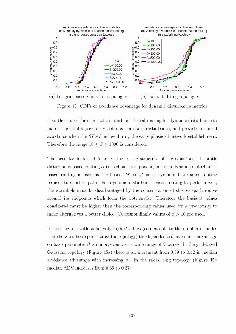
0.1 0.2 0.3 0.4 0.5 0.6 0.7 0.80
0.1
0.2
0.3
0.4
0.5
0.6
0.7
0.8
0.9
1
Avoidance advantage
Cum
ula
tive fre
quency
Avoidance advantage for active wormholesdelivered by dynamic disturbance−based routing
in a grid−based gaussian topology
β=10.0
β=100.00
β=200.00
β=300.00
β=500.00
β=1000.00
(a) For grid-based Gaussian topologies
0.1 0.2 0.3 0.4 0.50
0.1
0.2
0.3
0.4
0.5
0.6
0.7
0.8
0.9
1
Avoidance advantage
Cum
ula
tive fre
quency
Avoidance advantage for active wormholesdelivered by dynamic disturbance−based routing
in a radial ring topology
β=10.0
β=100.00
β=200.00
β=300.00
β=500.00
β=1000.00
(b) For radial-ring topologies
Figure 45: CDFs of avoidance advantage for dynamic disturbance metrics
than those used for α in static disturbance-based routing for dynamic disturbance to
match the results previously obtained for static disturbance, and provide an initial
avoidance when the SPAF is low during the early phases of network establishment.
Therefore the range 10 ≤ β ≤ 1000 is considered.
The need for increased β arises due to the structure of the equations. In static
disturbance-based routing α is used as the exponent, but β in dynamic disturbance-
based routing is used as the basis. When β = 1, dynamic-disturbance routing
reduces to shortest-path. For dynamic disturbance-based routing to perform well,
the wormhole must be disadvantaged by the concentration of shortest-path routes
around its endpoints which form the bottleneck. Therefore the basis β values
considered must be higher than the corresponding values used for α previously, to
make alternatives a better choice. Correspondingly values of β > 10 are used.
In both figures with sufficiently high β values (comparable to the number of nodes
that the wormhole spans across the topology) the dependence of avoidance advantage
on basis parameter β is minor, even over a wide range of β values. In the grid-based
Gaussian topology (Figure 45a) there is an increment from 0.39 to 0.42 in median
avoidance advantage with increasing β. In the radial ring topology (Figure 45b
median ADV increases from 0.35 to 0.37.
139

5.7.5 Static Versus Dynamic Disturbance For Fixed Worm-hole Locations
It was noted in Section 5.7.2, page 135 that static disturbance-based routing fre-
quently obtains avoidance advantage via an edge routing effect, through incentivising
routing towards the edges of the topology where the peer count was lower. However,
in cases in which the wormhole is located upon an edge, such an approach will not
lead to wormhole avoidance.
It is important to consider the performance of static versus dynamic disturbance-
based routing in cases in which the wormhole is located upon the edge of the topology.
This may arise, for example, in scenarios in which the attacker is known to control
a certain region of the topology, in which they would have the ability to place their
wormhole without detection. An active wormhole (the most challenging type for
detection) in a fixed location is tested across an ensemble of topologies. Metrics
values found to perform well in previous sections (α = 5.0 and β = 300) are used in
this comparison.
Figure 46, page 140 shows that for fixed wormhole location scenarios, the dynamic
disturbance protocol obtains better performance than the static protocol, with
static disturbance providing negative avoidance advantage in some cases, due to
its tendency for edge routing which leads towards the wormhole in this scenario.
In the case in which the wormhole is located upon the southern edge, selecting
dynamic disturbance-based routing as opposed to static increases median avoidance
advantage from 0.21 to 0.29. In cases in which the wormhole is located upon the
0.1 0.15 0.2 0.25 0.3 0.35 0.4 0.450
0.1
0.2
0.3
0.4
0.5
0.6
0.7
0.8
0.9
1
Avoidance advantage
Cum
ula
tive fre
quency
Avoidance advantage for active wormholes onsouthern edge of grid−based gaussian topology
Static (α=5.00)
Dynamic (β=300.00)
(a) Wormhole on southern edge
−0.2 −0.1 0 0.1 0.2 0.3 0.4 0.50
0.1
0.2
0.3
0.4
0.5
0.6
0.7
0.8
0.9
1
Avoidance advantage
Cum
ulat
ive
freq
uenc
y
Avoidance advantage for active wormholes oneastern edge of grid−based gaussian topology
Static (α=5.00)
Dynamic (β=300.00)
(b) Wormhole on eastern edge
Figure 46: Edge routing and the performance of static versus dynamic disturbance
140

eastern edge, the performance increment is more considerable. Static disturbance-
based routing obtains a zero median avoidance advantage, while dynamic is able to
obtain ADV = 0.28. The performance of dynamic disturbance-based routing is also
more consistent than static, with a narrower range of possible avoidance advantages
indicated on the CDF plot.
It is important for a security-conscious deployment that secure protocols perform
better than a baseline solution, in this case shortest-path routing. However, when the
wormhole is placed on the eastern edge (Figure 46b), static disturbance-based routing
achieves a negative avoidance advantage in 35% of cases. By contrast, the important
feature of dynamic disturbance-based routing demonstrated here is its stability and
consistently positive avoidance advantage. This illustrates the ability of the dynamic
disturbance protocol to locate active wormholes through their inherent bottleneck
effect. Therefore, dynamic disturbance-based routing is especially favourable for
stable performance in cases in which the attacker is known to control a particular
region of the topology in which their wormhole would be anticipated for deployment.
5.8 Securing Dynamic Disturbance Against Fol-
lowup Attacks
5.8.0.1 Preventing Dropping Of Shortest Path Replies
A potential security vulnerability of the dynamic disturbance approach is its reliance
upon the wormhole faithfully delivering reverse unicast replies for the shortest path
routes. Since the attackers deploying the wormhole have an interest in attempting
to defeat the protocol, it is possible for the wormhole to prevent disturbance from
accruing along earlier points in a path by dropping the first response seen. This
is only an advantage for the attacker if it is known that this disturbance scheme is
being used, since in its absence, dropping route responses would be likely to reduce
its exposure to traffic, preventing the wormhole from taking any part whatsoever in
routing.
If the attacker knows that the disturbance-based protocol is in use, then an extra
security measure can be implemented. This approach involves dispatching a periodic
flood from the sink node. This route update consists of a single packet containing
141
the largest node identities and their corresponding aggregate increments in SPAF for
nodes on all routes found to that destination during that interval. The nodes and
their peers apply these disturbance increments for the duration given in the packet.
This route update flooding mechanism serves to ensure the propagation of the most
significant disturbance changes to all network entities, regardless of attempts by
the wormhole to interfere by traffic-dropping. Since there are typically very few
destinations in a sink-oriented sensor network relative to nodes themselves, this
occasional flooding approach would not impose an excessive burden.
5.8.0.2 Authenticating Disturbance Increments
In order to prevent spoofing of shortest path route replies, or other protocol updates
from the sink, mechanisms can be used to authenticate them. A digital signature
could be employed, but as discussed in Section 3.6.3, page 63, if routing is particularly
frequent, the energy impact of the computation associated with the public key
operations could be excessive. Since all the route responses originate from a common
endpoint in a WSN (the sink) it is possible to use the one way hash chain approach
(Section 3.6.4, page 66) to authenticate route responses as part of a consistent
series delivered from the sink. This could distinguish any spoofed responses that
try to generate spurious disturbance, as malicious nodes could not generate an
authentic response as a result of not knowing the originally generated sequence
number presented by the sink.
5.9 Conclusion
This chapter has presented and analysed two distinct disturbance-based routing
protocols that can provide benefits for wormhole avoidance in WSNs; static and
dynamic disturbance-based routing. Although a variety of schemes already exist
to provide wormhole detection, they suffer many drawbacks, such as requirements
for centralised communication, unreasonable algorithmic complexity, inability to
integrate with realistic MAC schemes, and requirements for hardware that may
not always be available. Overall, the continuous usage of such wormhole detection
schemes imposes an energy burden in energy-constrained networks designed for long-
term deployment.
142

The disturbance-based approaches presented in this chapter, by contrast, provide
a way to embed awareness of possible wormhole locations into decisions made by a
distributed routing protocol based upon the standard AODV protocol. Routing away
from a wormhole reduces its exposure to network traffic, and therefore its ability to
aggregate traffic flows and therefore compromise or otherwise interfere with ongoing
network behaviour. Therefore, although these schemes cannot guarantee isolation
of the wormhole from the network, integrating wormhole avoidance into a routing
function that multihop networks must carry out anyway as part of its operation
makes the system more stable and secure by an additional layer of protection. If
data never reaches the wormhole, or uses it in reduced quantities, then its ability to
disrupt network activity is correspondingly reduced.
The static disturbance-based scheme presented has been shown to be capable of
avoiding both passive and active wormholes. This protocol uses a metric which
takes the topology structure and peer count of each hop into consideration along
the route. Passive wormholes are avoided based upon their peer inflation effect, in
which the wormhole creates strongly connected components. These are penalised by
the tendency of static disturbance to favour less densely connected network regions.
Active wormholes are avoided based upon the tendency to route to the edge of the
network. With a suitably tuned α = 10 value, static disturbance based routing
can produce an avoidance advantage of 0.5, corresponding to an additional 50%
wormhole-free routes.
Dynamic disturbance-based routing locates wormholes by forming an additional
shortest-path route which flows through them, and then using this route to
accumulate dynamic disturbance. The route itself flows through regions of low
dynamic disturbance. The dynamic disturbance-based protocol has been shown to
be capable of locating the wormhole through the bottleneck effect it generates in
operation, and delivers stable performance particularly in simulation scenarios in
which the wormhole is located upon the edges of the topology. In these situations,
dynamic disturbance-based routing is recommended for deployment.
Therefore, these approaches are suitable for deployment in existing networks, in
which energy or hardware constraints mean that no conventional wormhole detection
is permissible. They provide for continued network operation with wormhole-free
routes if the wormhole link is severed, and the ability to continue to provide network
service if the link is severed. These approaches provide a valuable complement to
143

the existing detection schemes and are capable of delivering defence in depth for
the overall network, by directing traffic away from regions in which a wormhole is
suspected or detected from topological or traffic flow characteristics.
144
Chapter 6
Wormhole Avoidance UsingReputation-Based Routing
6.1 Introduction
The previous chapter introduced a novel routing concept, disturbance-based routing,
as a countermeasure against the wormhole attack in sensor networks. This chapter
presents an alternative wormhole avoidance approach, reputation-based routing
(RBR), which is viable in topologies in which attackers will take time to deploy
their wormhole. A logarithmic reputation metric is demonstrated to create long-
term memory in the network that encourages reuse of nodes and links traversed
earlier, favouring the use of wormhole free paths even after a shortcut across the
network is introduced by a wormhole attacker. Simulation results are presented to
verify the performance of the reputation-based routing approaches.
Reputation-based routing is chosen to provide a viable wormhole avoidance approach
in scenarios in which it can be assumed that a stabilisation interval free of attack
exists. This is likely to be the case, for example, in scenarios in which the attacker
is assumed to be poorly resourced, or a deployment is spontaneous. The reputation-
based routing approach has the advantage of not requiring tunable parameters such
as the α and β values involved in the disturbance-based routing schemes. This
absence of parameters simplifies deployment by removing the requirement to consider
tuning the scheme to specific topology characteristics, which therefore improves the
simplicity of deployment. This chapter motivates the intuitions behind the novel
reputation-based routing approach [3], defines its metric and logic of operation,
and presents simulation results to demonstrate its performance characteristics for
standard topologies.
145

6.2 Overview of Reputation-Based Routing
The nature of the novel idea, reputation-based routing, presented in this chapter is to
provide routing that is resilient against the future introduction of a wormhole attack
via a conceptually simple and persistent reputation metric, updated and reinforced
by the dynamic traffic patterns at a particular node. In this section the nature of
the idea and its protocol operation will be defined and design consequences explored.
The goal of the approach is to introduce long-term hysteresis into routing decisions,
in which even though particular routes have expired, their constituent nodes remain
favoured candidates for later routing by the rest of the network.
The key idea is that in many attack scenarios there can be expected to be a
stabilisation interval from early deployment, during which the network will remain
free of threats. In a newly deployed network, before implementing a wormhole attack,
the attacker would be required to scan the topology, locate the sink, determine the
goals of the network, realise that a wormhole is the desired attack vector to gain
control of network routing, and implement their attack.
It can be assumed that this stabilisation interval will form a safe operational window
during which the network can operate unhindered, particularly if node deployment
is a gradual process and nodes self-organise to discover routes from their individual
activation. Within this interval, the nodes will perform their routing and data
dissemination along wormhole-free paths, loading the reputation metrics such that
these nodes become preferential nodes for inclusion in routes.
The protocol depends entirely on local calculations using overheard information as
part of the normal routing process. As a result, it does not impose any additional
overheads as seen in other wormhole detection mechanisms. Potential overheads
include sentry packets as in packet leashing (Section 3.5, page 56) or watchdog
packets for collaborative behaviour checking [53]. The underlying logic of the routing
protocol can operate using a standard and well-tested routing protocol for end-to-end
metric minimisation such as AODV [109]. This assists integration of the protocol
into existing sensor network operating systems, allowing it to use similar routing
logic but with a custom metric.
146

6.3 Philosophy Behind Reputation-Based Rout-
ing
Consider the case in which an attacker deploys a wormhole some time after the
network begins operation. Previously, it can be anticipated that routing protocols
carrying traffic to the sink would have taken relatively direct routes. However, when
the wormhole is introduced, the topology is suddenly changed dramatically, with
the wormhole presenting a shortcut across several hops. If a routing metric can
be devised in which the previous usage of those hops creates a sufficiently powerful
incentive to continue using them in the presence of the sudden topology change,
then the wormhole attack will fail to draw significant traffic. Figure 47, page 148
illustrates this, demonstrating the accumulation of reputation in the early phases
of operation that later leads those nodes to be preferred over a newly introduced
wormhole shortcut with no reputation.
The intuition behind the reputation routing protocol is to create suspicion regarding
topology changes and a resulting disincentive to use the newly available shortcut
route that a wormhole would introduce. The reputation metric is structured so
that even though the original routes have expired and the wormhole now provides a
shortcut route to the destination, the newly established wormhole and its surrounding
nodes do not have sufficient reputation to be selected. Thus, the reputation-based
routing protocol will treat these new routes with suspicion and will favour the routes
featuring trusted nodes until the alternatives are exhausted.
Figure 6.2, page 146 presents an overview of the reputation-based routing metric.
During the stabilisation interval, reputation levels have incremented upon nodes on
the route shown at the start of the sink. When the wormhole is introduced, the
nodes around its endpoint do not have sufficient reputation for the route through
the wormhole to be chosen for routing. Therefore, the safe route continues to be
located.
6.3.1 Reputation Metric Definition
Given a particular multihop route in the network, successful delivery of data to
an endpoint requires retransmission at all intermediate nodes along the route. If a
147

(a) During stabilisation interval (b) Following stabilisation interval
Figure 47: Operation of reputation based routing, preferring long-established routes
node is malicious and refuses to forward, or is subjected to destructive jamming
interference or the presence of a wormhole, then the route carries an increased
probability of failure. The challenge for an avoidance protocol is to determine the
probability that a wormhole or other security threat is located within a region.
It is possible to explore the use of an analytic approach, in which a priori information
about the structure and nature of an attack is explored to the individual link
probabilities. This approach was considered in Section 4.9, page 101 in an analysis
of signal jamming attacks.
However, in order to make the best selection of routes in an operating network in
which the precise form of the attack is unknown and no statistical assumptions about
the placement of wormholes help to structure the attack, a more robust mechanism
will use empirically sampled past performance to approximate these probabilities.
Therefore an estimate of the likelihood of routing success can be obtained from
historical information, using the concept of a per-node reputation level RLEV ELi.
This represents the reputation, and an aggregate of the trust placed in a node from
its successful forwarding. RLEVEL itself is bounded to one, a state that represents
complete trust of a particular node. Complete trust occurs when the bandwidth
demand of the route replies received is equal to the node response.
The reputation level of a single node is increased on each successful routing response
unicast back from the sink by RLEV EL INC, which is defined for new route R
by Equation 6.1 in terms of the bandwidth demand of the particular route BWR
(its data rate request carried in a routing header) and the data rate DRi of the
transceiver at Ni.
RLEV EL INC(R) =BWR
DRi
(6.1)
148

The reputation metric of a single link between nodes Ni and Nj, RMi,j is defined
as a function of the reputation level of the originator at that particular time t,
RLEV ELi(t), in Equation 6.2, page 149. The reputation metric is initialised to a
nominal reputation null constant (RNK) upon activation of the protocol. Therefore
for formation of the first route (before any reputation increments are received) the
behaviour of the protocol is effectively equivalent to shortest-path routing. The
nature of the logarithmic function employed is that as RLEV ELi tends to one, the
reputation metric of the nodes upon the path to the sink goes to zero.
RM i,j(t) =
{RNK if RLEV ELi(t) = 0
−ln(RLEV ELi) if RLEV ELi(t) > 0(6.2)
A node with data to transmit that does not have an active route to the sink, broad-
casts a RBR-RREQ, which is retransmitted at intermediate nodes, incrementing the
aggregate reputation metric stored in the packet as it travels. Upon receiving a new
reputation-based routing request, the sink chooses the end-to-end route with the
lowest aggregate reputation metric (representing the highest reputation levels and
thus the best choice), and unicasts the reply along the reverse route which serves to
increment the reputation level.
From this, routes featuring nodes with a high RLEVEL (which have previously
carried large amounts of traffic) will be rewarded strongly. The effect of this is
to make the reputation algorithm very cautious, biasing it heavily towards the use
of previously explored nodes, with a high reputation level, wherever possible. This
is precisely the effect desired to engineer a secure network.
6.4 Simulation Methodology and Validation
6.4.1 Scenario Definition
This section defines the simulation scenarios, which are designed to model a security-
critical hypothetical military deployment. The scenarios considered consist of a
fixed region of terrain, within which the network operator seeks to defend their
territory and track the motion of hostile enemy troop groupings. Homogeneous
detection nodes are arranged within this region, using the standard topologies defined
in Section 4.8, page 96. This ensures that topologies employed are representative of
149

a wide variety of network situations, in which terrain prohibits an optimal regular
deployment.
For the grid-based scenarios, the sink is located at the military headquarters upon
the northern edge of the topology. For the radial ring topologies, the sink is
located centrally. The malicious attacker chooses to deploy one of their wormhole
endpoints within a one-hop distance from the sink. The remote pickup endpoint
of the wormhole is located upon the midpoints of either the southern edge of the
topology.
In this scenario it is assumed that, immediately following the stabilisation interval,
the attacker activates their wormhole. This could either occur by the deployment
of the endpoints, or the activation of the link between them. Following this, future
routing packets and responses are tunneled through the wormhole, which allows allow
it to control routing as usual in the case of an attack.
Armies move in a randomly selected direction, reflecting of the boundaries of the
southern half of the deployment region. At the new flow interval on approach of an
army within detection range of an idle detection node, routing to the sink is initiated
according to the defined protocol. Network routing is updated at each routing
interval, and flows remain active at their given flow rate for their specified route
lifetime. During simulation, the wormhole is activated after the stabilisation interval,
and then begins to propagate traffic as intended. The simulation is implemented as
a custom program in the OCaml programming language [92].
6.4.2 Simulation Methodology
The simulator generates an ensemble of topologies. In each topology, connectivity
between nodes is modelled according to a standard protocol model (as described in
Section 4.4.3, page 85), assuming bidirectional binary connectivity within a given
peer distance threshold PR. This assumes that a link is connected if its endpoints
lie within the range PR, and disconnected if they are outside of this. For simplicity,
the maximum sensing range SR within which the nodes will detect troops, is set
equal to the communication range. Periodically, at the new flow interval during
simulation, the fresh position of each troop cluster is recomputed using their known
velocity, previous position, and the time delay. The simulator checks for idle sources
150

surrounding each troop cluster within SR, and proceeds to activate the nearest idle
source for reporting. Reputation level increments are applied to the route with the
lowest aggregate metric.
6.4.3 Success Metric Definition
The metric employed to analyse reputation-based routing is the avoidance advantage
ADV. The simulator records a metric to assess the success of reputation-based
routing with the given topology properties. The avoidance advantage (ADV) is
the additional proportion of all discovered routes throughout the simulation that
successfully avoid the wormhole under the disturbance scheme as compared to
shortest path. A value of zero corresponds to a state in which the disturbance-
based scheme delivers no advantage, as precisely the same proportion of routes used
the wormhole as in shortest path routing.
6.4.4 Simulation Validation
This section considers validation of reputation-based routing simulations. The core of
reputation routing simulation is based upon the software developed for disturbance-
based routing (Chapter 5), and therefore inherits the tests for the routing and results
generation demonstrated in Section 5.6.4, page 127.
6.4.4.1 Single Circle Topology For Reputation-Based Routing Validation
This section will consider a simple single circle topology, and the behaviour of the
reputation-based routing protocol within it. Simulation behaviour will be compared
against an analytic model to verify correct computation of the reputation-based
routing metrics with additional routes, and correct routing decisions according to
the protocol logic.
Consider a simple topology as depicted within Figure 48, page 152. This circular test
topology contains C = 16 uniformly spaced nodes around the circle, with the sink
node as one of them with index N1. The connectivity of the topology is sufficient to
connect all adjacent nodes within the circle. Node N2 is originally disabled. As a
result the data transmissions from node N3 at the start of network activation must
form a multihop route counter-clockwise all the way around the circle.
151

−300 −200 −100 0 100 200 300−300
−200
−100
0
100
200
300
N1
N2
N3
X Position (m)
Y P
ositio
n (
m)
Circular topology used for reputation−basedrouting simulation validation
Figure 48: The circular test topology
6.4.4.2 Validating Reputation-Based Routing Against Analysis
After a given time interval Tchange, disabled node N2 is activated. This models the
process by which a wormhole changes the connectivity properties of the system. A
potential shortcut is now available in which node N3 is connected to the sink via
an intermediate clockwise hop through N1. In order to provide wormhole avoidance,
reputation-based routing should however choose to reject the shortcut in favour of the
previous counterclockwise route. This occurs when sufficient reputation has accrued
for the route to have a lower overall reputation metric, despite its overall increased
length.
Upon its initialisation, the node N2 upon the newly introduced shortcut does not
have any reputation, and therefore the metric for the hop using it is the reputation
null constant RNK (Equation 6.2, page 149). Since only the intermediate hops
and not the originator itself contribute to the reputation metric, the shortcut route
metric only contains the contribution from the link leaving N2. For a reputation
level RLEV ELmin at which the previous counterclockwise route will be equal in
aggregate metric to the shortcut, the following must hold:
RNK = −C∑i=4
ln(RLEV ELmin) (6.3)
152

The reputation upon all previously used nodes will be a constant, due only a single
source N3 being previously activated. Therefore the summation can be replaced
with the number of nodes contributing to the reputation. This gives the following
relationship between the parameters:
RNK = −(C − 3)ln(RLEV ELmin) (6.4)
In order to verify this relationship, the simulation results were contrasted with this
analytic prediction. The simulation proceeded by generating the previously described
circular topology, with N2 adjacent to the sink disabled. Given a reputation level
target and a particular value of the null constant RNK, initial routes were formed
until the reputation level equalled this value. At this point, the disabled node was
reactivated to offer a shortcut route. Success was recorded for the trial if the counter-
clockwise route was used, and failure if the shortcut was used. Figure 49, page 153
shows an example of failure and successful cases during this routing operation. In
the successful avoidance case, K = 10 and RLEV EL = 0.5, which is, as predicted
analytically, sufficient reputation to continue using the counter-clockwise route. In
a failure case, K = 10 and RLEV EL = 0.4.
(a) Avoidance success case (b) Avoidance failure case
Figure 49: Simulation of reputation-based routing in the simulation test topology
Figure 50, page 154 demonstrates a match of simulation performance with the
analytically predicted values. This validation test is conducted in a single circle
topology consisting of C = 16 nodes (including the sink as N1). The figure shows
the minimal value of RNK which allowed the reputation-based routing protocol to
successfully use its original route in the presence of the shortcut. This was found
using a bisection method, beginning with a range of RNK values from 0 to 50.
153

This range was iteratively bisected and the midpoint tested, to discover the smallest
value of RNK that produced successful avoidance of the shortcut. It is clear that
the simulation results for minimal required RNK are precisely as predicted by the
equation. This serves as validation of the simulator logic for route establishment and
computation of the reputation metrics.
0.1 0.2 0.3 0.4 0.5 0.6 0.7 0.8 0.90
5
10
15
20
25
30
RLEVEL at shortcut establishment
Min
imum
RN
K r
equired for
RB
R to c
ontinue u
sin
g o
rigin
al ro
ute
Simulation and analytical comparison of minimalreputation null constant (RNK) required to avoid shortcut
RNK found from simulationAnalytically predicted minimum RNK
Figure 50: The relationship between RNK and RLEVEL
6.4.5 Default Parameters
Unless otherwise specified, the parameters displayed in Table 4 are employed to
generate the full simulation results for this chapter. The topologies employed are
those standard topologies as specified in Section 4.8, page 96.
6.5 Results
This section describes and analyses the performance of reputation-based routing
in ensembles of grid-based Gaussian, radial ring and uniform random topologies
(Section 4.8, page 96). The results use a stabilisation interval of Si = 200 seconds,
154

Parameter Symbol Default ValueSimulation run topology ensemble size 50Simulation runtime 3000 secondsStabilisation interval Si 200 secondsRouting interval 10 secondsRoute lifetime 100 secondsBandwidth demand BWR 5kbit/sChannel data rate DR 250kbit/sGrid based Gaussian regularity factor Rf 0.9Topology edge size S 1000mPeer communication distance PR 150mGrid based Gaussian node count N 100Radial topology ring count RMAX 6Radial topology ring separation s 100 (m)Radial topology radian separation kr 0.9
Table 4: Default parameters employed in simulation results
corresponding to the lifetime of 20 routes. Following the stabilisation interval, the
wormhole is deployed and activated by the attacker. The wormhole remote pickup
endpoint is located at a fixed location in the midpoint of the southern edge or eastern
edges of the topology. These correspond to the cases in which the attacker controls
a fixed edge region of the topology far from the sink and is able to install their
wormhole in this region.
Figure 51, page 156 illustrates the avoidance advantage provided by the reputation-
based routing scheme in the described scenario across an ensemble of 50 topologies.
These results are presented as a cumulative distribution function to allow the range
of avoidance advantage values across the ensemble of topologies to be examined and
any outlier results identified. The performance for the highly regular topologies is
very consistent. For the wormhole located upon the southern edge in grid-based
Gaussian topologies, the median avoidance advantage is 0.97, and for the radial ring
topology it is 0.87. Reputation-based routing always delivers an avoidance advantage
above 0.8 in the case of southern wormhole placement in the grid-based and radial
topologies.
The grid-based Gaussian topology result is considerably better than that achieved by
the dynamic disturbance-based routing scheme in Section 5.7.5, page 140. With edge
wormhole placements, the best avoidance advantages generated in the grid-based
Gaussian topology were below 0.4. Therefore, reputation-based routing can deliver
twice the avoidance advantage of dynamic disturbance in this regular topology. This
155

0 0.1 0.2 0.3 0.4 0.5 0.6 0.7 0.8 0.9 10
0.1
0.2
0.3
0.4
0.5
0.6
0.7
0.8
0.9
1
Avoidance advantage
Cu
mu
lative
fre
qu
en
cy
Avoidance advantage delivered by reputation−basedrouting under different topology structures
South wormhole, grid−based gaussianSouth wormhole, uniform randomSouth wormhole, radial ringsEast wormhole, grid−based gaussianEast wormhole, uniform randomEast wormhole, radial rings
Figure 51: Distribution of avoidance advantage for reputation routing, under varioustopology ensembles
is due to the reputation buildup during the stabilisation phase across these highly
regular topologies, which create tendencies to use these stable routes again from any
nodes in the network.
For both wormhole placements, in the uniform random case there are some cases in
which reputation-based routing fails to deliver such consistent performance. These
have been investigated and shown to be those in which the local connectivity
properties disadvantage the wormhole under the metric chosen. For example, the
avoidance advantage metric is defined relative to how many routes would use the
wormhole anyway under shortest path. If the wormhole placement site is poorly
connected within the topology graph and thus offers an unfavourable shortcut, it
may not achieve an advantage since it may be unreachable under either shortest
path or reputation-based routing. This is not however a security failure, as the
attackers will fail to achieve a significant gain from their wormhole.
This highlights a potential issue for deployment of reputation-based routing in
irregular topologies. If the topology is sufficiently irregular that all traffic is bridged
under a single link, then it is likely that introducing a wormhole next to this link
could hijack its reputation. Therefore a condition for deployment of the scheme
is that, if randomly deployed, the topology must guarantee sufficient connectivity
along a variety of redundant paths (beyond the requirement for mere reachability of
all nodes from the sink) to ensure an effective flow of reputation to the sink.
156

6.6 Conclusions
This chapter has introduced reputation-based routing, the motivation behind its
introduction, and the logic that allows it to successfully avoid wormhole attack
introduced after a given stabilisation interval, via its hysteresis which causes it to
favour previously established routes for future routing following their expiry.
Simulation results have demonstrated the performance of reputation-based routing,
showing a high avoidance advantage in topologies in which wormholes exist at a fixed
location. It has been shown that the scheme is capable of operating successfully at
schemes with a short stabilisation value. As long as the network as deployed can
achieve full connectivity across a variety of diverse paths, implying that the topology
must be sufficiently regular, reputation-based routing can avoid wormholes with high
probability.
157

Chapter 7
Sybil Avoidance Using HybridMultihop and Supernode Routing
7.1 Introduction
Chapter 4 introduced the fundamental relaying concepts for supernode data transfer,
and analysed the vulnerability of supernode routing relative to multihop routing
for attacks such as homogeneous signal jamming. However, it is important to
consider the supernode data delivery methodology not as a complete replacement
for multihop routing, but instead as a complementary element that fits within a
multihop routing topology. Accordingly, it is valuable to consider how routing
technologies can accommodate supernodes to deliver good network-wide performance
and reliable end-to-end routing. This chapter introduces the integration of physical-
layer information to support reputation routing in the presence of supernodes,
defining the physical reputation-based routing (PRBR) protocol.
Given the fluctuations in deployment density in stochastic topologies, together with
the necessity for central coordination to manage these supernodes, it is likely that
nodes will not always be able to reach a supernode coordinator, or that supernode
data delivery will not always succeed, requiring retransmissions which will lead to
capacity reductions. Therefore, a requirement for robustness suggests that multiple
data relaying mechanisms should be made available, and that the choices between
them should be dynamic if possible.
Furthermore, a multitude of issues, from temporary obstructions of nodes due to
shadowing from mobile obstructions, time-dependent changes such as slow fading
158

Figure 52: Options for routing in the presence of intermittently reliable supernodes
[95], to malicious jamming attacks from external devices (Section 4.9, page 101) can
change network conditions and thus complicate supernode data delivery. Therefore,
even if a node is close to a particular supernode, it is possible that alternative
mechanisms may provide better performance for data delivery. Figure 52 illustrates
options for data relaying, illustrating a node adjacent to an unreliable supernode
(following malicious attack) but with the options of relaying via a more reliable
supernode at a greater distance (illustrated dotted line), or using a pure multihop
route to the sink (dashed line).
7.2 Overview of Physical Reputation-Based Rout-
ing
This chapter considers a hybrid routing model in which multihop routing is used
by data originators to reach a supernode coordinator. Reputation-based routing,
introduced in Chapter 6 is modified to use cross-layer information from the physical
layer, forming physical-reputation-based-routing (PRBR). This protocol takes into
account physical layer information, using the SINR of any supernodes comprising the
final link in the route. As the supernode is the final limiting factor in delivery success,
this is a critical parameter for assessing future data delivery success. By assessing
these physical-layer parameters, the PRBR protocol can progressively during network
operation learn the performance characteristics of these supernodes and distribute
159

this knowledge throughout the network as part of route formation. If a supernode
consistently delivers high performance at the physical layer, then it is reinforced and
becomes more likely to feature in multihop routing from other sources.
The advantages of this approach include increased robustness. Should a supernode
fail to deliver the idealised physical layer gain, as a result of physical-layer issues such
as channel changes (brought about by obstruction), or local oscillator instability,
then this will be reflected in a poorer performance as determined by the sink upon
reception. In this case, it is likely that alternative supernodes should take over,
allowing those suffering from impaired performance to relay a reduced amount of
traffic.
This fits the security principle of using a diverse series of fallback mechanisms, and
graceful degradation. An important part of forming a robust network is adaptation
to observed performance characteristics. Using physical reputation-based routing,
nodes do not automatically route through the closest supernode coordinator, but
attempt to discover the most stable routes with the highest SINR for the relaying
phase, in turn updating reputation metrics in accordance with their decision.
This approach provides stability by directing traffic away from supernodes where
performance may be intermittent, whether through malicious attack or connectivity
problems. One particular malicious attack which may impair supernode performance
is the sybil attack, discussed in Section 3.3.3, page 53.
Upon initiating routing for a new source, selection of the forwarding path depends
upon relative performance of the network’s supernodes, so those which are likely to
be less reliable in delivery and require increased retransmissions will see the load
that they are carrying reduced quickly. A final aspect of resilience provided is the
ability for participating nodes to form a multihop route direct to the sink, which
constitutes fault tolerance, in which the network reverts to a conventional multihop
network with data delivery to the sink in cases of supernode failure. Through this
mechanism it is always possible to fall back to multihop data delivery if performance
of all available supernodes is poor.
160

7.3 Sybil Attack
7.3.1 Sybil Attack In Multihop Networks
The sybil attack, discussed in the literature review (Section 3.3.3, page 53) is an
identity spoofing attack in which nodes fabricate additional identities. These false
identities allow them to participate multiple times in protocols, thus compromising
distributed voting or other protocols that depend upon distributed decisions or
consensus. The sybil nodes may compromise the diversity of multihop routing, by
creating unexpected single points of failure. In a similar manner to the wormhole
attack where multiple paths converge on a link under the control of the attacker,
multiple routes converge at a single physical node. This leads to a network in which
the attacker can very easily implement a selective forwarding or complete denial of
service attack, subverting the normal diversity of intermediate forwarding nodes and
links that would normally limit the control a single node can obtain. An example
is illustrated in Figure 53a, page 163. From the perspective of sources S0, S1 and
S2, traffic is sent along several diverse multihop routes that do not share a node in
common. However, since one of malicious node M’s sybil identities A, B or C is
included on all three paths, M has defeated the diversity of multihop routing and
controls all traffic in the network.
7.3.2 Sybil Attack in Distributed Beamforming Supernodes
The sybil attack has a different effect which impairs the performance of a beamform-
ing network, through its inability of a sybil node to fulfil the level of commitment
claimed. In the event that one of the nodes participating in a supernode to
perform beamforming is actually a sybil node, phase S3 (the distributed beamforming
transmission phase to the sink) does not include as many SNMs as the coordinator
anticipated from the acknowledgements received in dissemination phase S1.
This is because some of the participating nodes from the perspective of the
coordinator are merely sybil identities, and ultimately underlying these virtual
identities there is only one single physical node, with a single transceiver. Therefore
the true number of SNMs participating in the beamforming transmission must be
lower than expected by the coordinator. This leads to a lower possible theoretical
161

peak SINR at the sink node receiving the beamforming transmissions, and therefore
the probability of successful reception is reduced.
The motivation of the attacker in performing a sybil attack may not be to compromise
beamforming intentionally; their motivation could be the desire to compromise other
distributed services such as data aggregation schemes, or key establishment. In this
case, it can be considered that the attack is implemented by code modification as a
custom module of malicious code deployed onto conventional network nodes, which
otherwise function undisturbed as intended by the defender. In this case, the sybil
node will still make a beamforming transmission from its single authentic physical
identity.
Given that the sybils in the network are malicious, if they are aware of the
beamforming architecture in use, performance can be reduced further. One power-
efficient example would be selective forwarding: participate in the first phase of the
beamforming protocol, giving agreement to participate to the coordinator in phase
S1, and then fail to make the transmission as agreed. In this case, the received SINR
at the sink would be as if only the non-malicious nodes participated, as it will not
include any contribution from the sybil nodes. This is the pessimistic case considered
in the model employed in this chapter. Figure 53b, page 163, demonstrates this with
a sybil node M around supernode coordinator C, which has two additional false
identities MS1 and MS2. Although the coordinator expects six nodes including
itself to participate, only three nodes make the transmission since M declines to
transmit.
The PRBR protocol is shown to penalise supernodes subject to the sybil attack as
candidates for routing. In addition to the benefits that routing over a supernode
with a high SINR offers for resilience, this also draws traffic away from the sybil
nodes, which being malicious nodes are under the control of the attacker and thus
should be given as little exposure to network traffic as possible.
7.4 Physical Reputation-Based Routing Protocol
This section presents and explains the physical reputation-based routing protocol
(PRBR), its foundational logic, equations and parameters. It operates by analogy
to reinforcement learning, in that it rewards relaying supernodes with desirable
162

(a) Multihop routing (b) Beamforming
Figure 53: The interaction of the sybil attack with multihop routing and beamform-ing
characteristics, in this case a consistently good physical layer performance. One
difference in philosophy compared to conventional reinforcement learning is that
the protocol does not use reputation decrements, which during development were
found to decrease performance. The protocol does contain a mechanism for
allowing reputation to expire, which enforces a relatively short lifetime, maintaining
continuous pressure towards exploration over the long term.
7.4.1 PRBR Introduction
Although the supernode provides a direct physical link to the sink node via a single
hop, it may not be possible for every node in the network to make direct beamforming
transmissions, whether due to insufficient deployment density of participating nodes
around a coordinator, or malicious attack such as presence of sybil nodes in a region
(Section 3.3.3, page 53). Therefore, it is necessary for these nodes to use multihop
routing, either to reach a supernode coordinator or directly to the sink node.
Reputation-based routing [3] (Chapter 6) has demonstrated advantages in avoiding
late-established wormhole threats in a multihop network, by prioritising routes
established during the early threat-free period. A modification of RBR to form
PRBR is shown to have utility in finding reliable supernodes for routing.
The PRBR protocol operates upon each node that is not a supernode member.
Supernode members use their local supernode to relay their traffic, passing it to the
coordinator for dissemination during stage S1. The protocol for PRBR performed
by nodes that are not supernode member nodes (SNMs) is based on conventional
reputation-based routing (RBR) for multihop networks (Chapter 6). It modifies the
163

routing request phase so the sink selects the highest reputation metric, which is set
by the physical-layer SINR value of the last hop, not the traffic load of the newly
initiated route as in RBR.
A difference between the RBR and PRBR presented in this chapter is that PRBR
stores reputation values for links and not merely individual nodes, and computes
aggregate metrics upon a set of links traversed and not merely the nodes upon the
route. The tasks for which the two protocols are applied is different, in RBR it
is for wormhole avoidance, while PRBR is required for link selection and therefore
benefits from the ability to select on the basis of link reputation values. The use of
link metrics rather than node metrics has been shown to provide the best empirical
performance.
7.4.2 PRBR Protocol at Nodes Not Supernode Members
A metric assesses the quality of links for routing based upon their physical-layer
characteristics. Initially, reputation level RLEV ELi is initialised to zero for all
nodes. This causes the reputation metric RM to take the value of the reputation
null constant RNK, which is initialised to a nominal high value. Effectively, in this
case with a null reputation level as exists at initialisation, the protocol is equivalent
to shortest path routing.
From this the reputation metric RM is used in end-to-end routing, as defined in
Equation 7.1, page 164. The logarithmic nature of RM allows the end-to-end values
to respond rapidly to changes, in which reliable routes quickly become favoured for
forwarding. The best route, chosen for data delivery, is that with the lowest end to
end RM sum.
RM i,j(t) =
{RNK if RLEV ELi(t) = 0
−ln(RLEV ELi) if RLEV ELi(t) > 0(7.1)
Any node which wishes to route to the sink begins the PRBR protocol. A node which
is not a supernode member broadcasts a request packet (PRBR-RREQ), which is
rebroadcast at intermediate receivers not with a sufficiently fresh route, until it
reaches the sink. These intermediate receivers include the supernode coordinators,
which perform a beamforming transmission (via the mechanisms in Section 4.5.2,
page 89) to deliver their data to the sink. The sink measures the incoming SINR
of the transmission of the RREQ and uses its values relative to the historical SINR
164

information for all supernodes in the network to determine a reputation increment,
using the strategy given in Section 7.4.3, page 165.
A conventional multihop route response from the sink is also received, and can be
used as a fallback if the supernode route formation process fails. This transmission
is assigned a nominal SINR equal to the minimal detection or decoding threshold of
the modulation scheme employed.
The sink then assesses the received routes, chooses the one with the highest
reputation metric, and delivers a route response (PRBR-RREP) which propagates
along the reverse path. If multiple PRBR-RREP packets have the same aggregate
metric, then the selection is made based upon the physical SINR of the supernode
that delivered the final hop to the sink. The reply PRBR-RREP from the sink is
transmitted during the next S0 period of supernode control and establishment. From
the supernode coordinator, it is unicast along its reverse path and propagates back
to the route originator. If the sink chooses to apply a reputation increment, then the
PRBR-RREP packet triggers increments to reputation level RLEVEL values upon
the nodes that it passes on the reverse reply. Upon reaching the originator, this node
uses the route contained in the packet to begin transmitting its data.
Therefore a supernode which is transmitting intelligible packets with high SINR is
continuously reinforced, encouraging its used for transmissions from nodes all over
the network, in addition to future transmissions from the current originator. In
the language of reinforcement learning, this represents a very strong reinforcement
of routes and partial route sections which have shown desirable performance
characteristics for relaying data.
7.4.3 Determining Reputation Increments
Upon successful reception of the RREP, the sink may, if the route is of sufficient
quality, apply a reputation level increment to the route through the best supernode.
RLEVEL is incremented by RLEV EL INC upon the nodes along the chosen route,
to a maximum of one. The magnitude of this increment is specified in Equation 7.2,
page 165. All signal-to-interference ratios employed are in logarithmic units.
RLEV EL INC =SINRr − SINRmin
SINRmax − SINRmin
(7.2)
165

The magnitude of reputation delivered for a chosen route featuring a supernode is
governed by the measured SINR of the beamforming transmission of the PRBR-
RREQ to the sink, SINRr, relative to the best SINRmax and worst SINRmin
received at the sink over the course of the network operation. These function as high
and low water-mark values, adjusting dynamically to the measured performance as
the network runs. These include the current SINR samples SINRr from the route
request under consideration. As a result, supernodes that perform very well receive
a high increment in reputation.
An important characteristic inherent in the supernode delivery is that transmissions
must meet a certain minimal reputation reward threshold SINRthresh for any
reputation increment to be applied. Below this, routes are considered insufficiently
low quality to receive any reputation increment. PRBR uses a dynamic strategy in
which a fixed proportion of the best performing supernodes in the network receive
the reward.
To track supernode routes that should be rewarded, the sink maintains history of
supernode performance values per route request, and ranks the SINR of incoming
requests relative to each other. If a supernode transmissions SINR is not in the
highest PBEST proportion, the current route does not receive a reputation increment.
A hard minimal cutoff SINRcutoff is also defined, below which no reputation
increment is received regardless of relative performance. This is anticipated to
be set to the decoding threshold for a particular scenario, plus a certain margin
to account for link change or other performance problems. Therefore, even if a
supernode is in the highest PBEST proportion of performers, if all performers are poor
it does not receive increments. This is a static constraint that prevents the system
from delivering reputation increments to supernodes performing below a predefined
physical limit. This ensures that the network would prefer multihop routing over
potentially unreliable supernodes, or supernodes suffering the presence of lots of
sybils in their vicinity.
Upon network initialisation and the setup of the sink for data reception, the minimal
SINRmin and maximal SINRmax tracking values are initialised based upon the
reputation reward threshold value SINRcutoff :
SINRmin ← SINRcutoff
SINRmax ← SINRcutoff + 1(dB)
166

7.4.4 Gradual Expiration of Reputation
Information gathered about local performance frequently reflects transient be-
haviour. For example, in multihop routing protocols, links may intermittently fail
and reactivate before routing protocols can compensate for this [40]. This can be
expected to be even more true for supernodes, given their collaborative transmissions
and the necessity for phase stability for a successful transmission. Therefore, it is
useful for ensure reputation information remains current, via a mechanism in the
protocol which removes old reputation information. By doing so, initial decisions
(such as an exploratory choice of a poor supernode) will be automatically reversed
if not continually refreshed by other reputation increments. By contrast, well-
performing supernodes will be reinforced continually through the ongoing traffic
that they contain, encouraging not just their continual use from the same sources
but from other nodes.
The mechanism chosen to implement this is exponential decay of reputation values.
Accordingly, unless an increment is applied the reputation level at each link is
exponentially decreased, each time intervals tINT by a constant decay factor Df ,
as illustrated in Equation 7.3. A decay factor value of Df = 0.99, when tINT is equal
to the average route lifetime, gives a half-life to the data of approximately 70 route
requests.
RLEV ELi(t+ tINT ) = DfRLEV ELi(t) (7.3)
7.5 Simulation Methodology and Validation
7.5.1 Simulation Methodology
The simulation is implemented in MATLAB. Firstly a topology realisation is
generated and supernode clique memberships established. The source activation
model is random, with three sources activated per routing interval. Routes are
computed to all potential supernodes coordinators using the reputation level values
for the network graph to calculate RMi,j for all links and the route with the
lowest aggregate reputation metric is chosen and reinforced with an increment. The
reputation increment received for these routes depends upon the appropriate sink
SINR for the simulated supernode transmission, which takes into account supernode
transmission with a specified level for the aggregate transmission. Exponential decay
is applied to the all route level values to according to Equation 7.3.
167

7.5.2 Simulation Validation
This section considers validation of the simulations for physical reputation-based
routing (PRBR). The simulation software for this chapter is implemented using
MATLAB. The routing engine is based upon the prototype which was developed for
disturbance-based and reputation-based routing, and successfully validated against
an independent implementation in OCaml in Section 5.6.4, page 127.
7.5.2.1 Fixed-Supernode Topology For Simulation Validation
In order to validate the simulations, a simplified topology was employed, the fixed-
supernode topology, in which supernodes are considered as abstract entities whose
performance was hard-coded into the simulation topology. This simplifies the simula-
tion by removing issues of supernode member recruitment and resulting performance
variations, and helps in validating the simulations by making anticipated behaviour
analytically tractable. Figure 54, page 169 shows an example topology, with a single
source and three candidate supernodes with sink SINRs performances of 12dB, 0dB
and −4dB. All three supernode coordinators are reachable from the source node S
through a member node on their boundary.
7.5.2.2 Validating Selection Of Best Candidate Supernodes
PRBR routing makes its selection of supernodes as a result of the reputation metric
values. When no reputation is applied at the beginning of the simulation, all link
metrics are equal to the reputation null constant (RNK). In this case, PRBR-RREQ
packets will be flooded through the possible supernodes and reach the sink with equal
reputation metric, but a decision will be made between them on the basis of physical
SINR. The route with the highest SINR will be reinforced. From then, its repeated
reinforcement will cause it to be chosen for all subsequent routing requests from S.
For example, in Figure 54, the supernode with a 12dB SINR will be consistently
selected for future requests.
Figure 55, page 170 shows this, illustrating the SINR for all routing requests across
100 trials of supernodes with fixed performance. 20 sequential routing requests
were made from the source, with a new routing request after the expiry of the
168
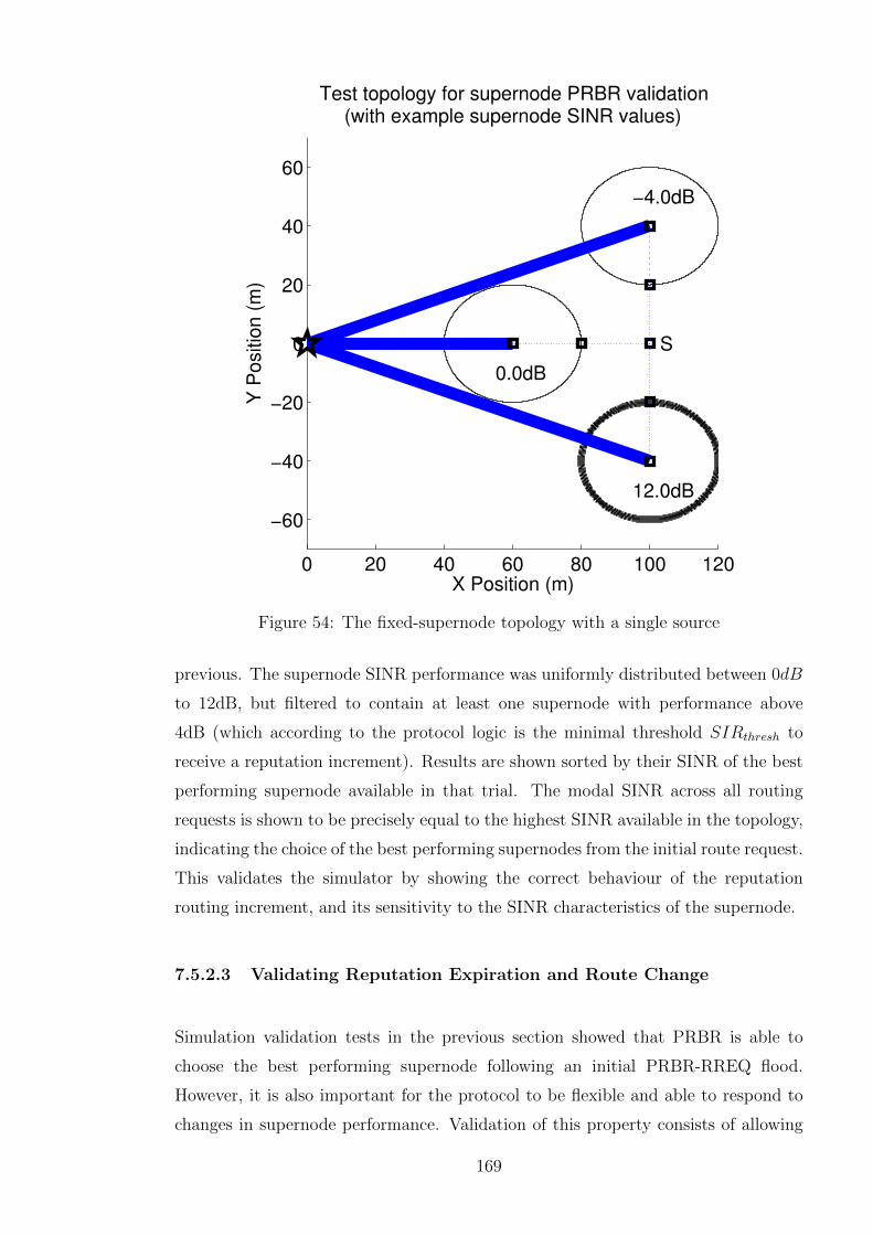
0 20 40 60 80 100 120
−60
−40
−20
0
20
40
60
Test topology for supernode PRBR validation(with example supernode SINR values)
X Position (m)
Y P
ositio
n (
m)
S
12.0dB
0.0dB
−4.0dB
Figure 54: The fixed-supernode topology with a single source
previous. The supernode SINR performance was uniformly distributed between 0dB
to 12dB, but filtered to contain at least one supernode with performance above
4dB (which according to the protocol logic is the minimal threshold SIRthresh to
receive a reputation increment). Results are shown sorted by their SINR of the best
performing supernode available in that trial. The modal SINR across all routing
requests is shown to be precisely equal to the highest SINR available in the topology,
indicating the choice of the best performing supernodes from the initial route request.
This validates the simulator by showing the correct behaviour of the reputation
routing increment, and its sensitivity to the SINR characteristics of the supernode.
7.5.2.3 Validating Reputation Expiration and Route Change
Simulation validation tests in the previous section showed that PRBR is able to
choose the best performing supernode following an initial PRBR-RREQ flood.
However, it is also important for the protocol to be flexible and able to respond to
changes in supernode performance. Validation of this property consists of allowing
169

0 20 40 60 80 1005
6
7
8
9
10
11
12
Demonstration of best supernode selection byphysical reputation−based routing (PRBR)
Trial index (sorted by increasing SINR available)
SIN
R (
dB
)
Max SINR of supernode available in topology
Modal SINR of supernode choice
Figure 55: Supernode SIR selection for a single-source fixed-supernode topology
reputation to decay, in the presence of supernode performance change, and validating
that the simulator respects analytically predicted behaviour in selection of a new
supernode.
Consider the situation in which the performance of supernodes has changed, due to
node failures, the introduction of sybil nodes, or physical-layer factors such as slow
fading. From the structure of Equation 7.2, page 165, since the SINR of the best
supernode will by definition by equal to SINRmax (the best SINR the sink has seen
over network operation), the reputation metric delivered will be unity along the route
to that supernode. Since reputation levels are bounded to unity, the reputation levels
upon this route will remain at this value until the exponential decay according to
Equation 7.3, page 167 reduces the metric sufficiently to make an alternative route
the better choice.
According to the protocol logic for reputation expiry (Section 7.4.4, page 167), upon
every decay time interval tINT the reputation level at a node is multiplied by a decay
factor, Df , where 0 < Df < 1. Assume that the metric at a certain time is unity, and
that no further reinforcement is delivered after this. In the fixed-supernode topology
all possible routes to a supernode are of equal length, due to the source S being two
hops from all supernode coordinators. Therefore if (i, j) is a link on the route with
170

existing reputation, after a time Tchange after the last request, the optimum route
will change when the reputation metric upon the previously used link i, j is equal to
the null constant RNK offered by the alternative route:
RMi,j = −ln(DTchange/tINT
f ) = RNK (7.4)
The time at which the routing change is anticipated under this analysis, Tchange, can
be computed from the PRBR parameters by rearranging the equation:
Tchange =−RNK.tINTln(Df )
(7.5)
The simulation was validated against the analytic equation given by the following
methodology. The original scenario before the supernode performance change is
depicted in Figure 56a, page 171. A single transmission is made with this scenario,
which establishes reputation levels upon the route chosen as unity. After the first
routing request is finished, supernode performance changes, as depicted in Figure
56b, page 171. Notably, the lower supernode declines from 12dB to 5dB, at which
point performance is marginal and it would be advantageous to use another. The
best decision in terms of physical-layer performance for future routes would be to
use the upper supernode which obtains 12dB SINR.
0 50 100
−60
−40
−20
0
20
40
60
Test topology for supernode PRBR validation(with example supernode SINR values)
X Position (m)
Y P
ositio
n (
m)
S
12.0dB
0.0dB
−4.0dB
(a) Before SINR performance change
0 50 100
−60
−40
−20
0
20
40
60
Test topology for supernode PRBR validation(with example supernode SINR values)
X Position (m)
Y P
ositio
n (
m)
S
5.0dB
0.0dB
12.0dB
(b) After SINR performance change
Figure 56: A fixed-supernode topology in the presence of supernode SINR perfor-mance change
After a given delay to allow reputation to expire (during which no routing requests are
performed), another routing request is made. If reputation has decayed sufficiently,
the upper supernode, with performance of 12dB, will be chosen for routing. If
this process does not succeed, then the simulation is repeated with an increased
171

0.1 0.2 0.3 0.4 0.5 0.6 0.7 0.80
500
1000
1500
2000
2500
3000
Minimal Tchange
to allow
reputation decay with decay factors
Decay factor Df
Tchange (
s)
Smallest simulated time interval Tchange
to switch routing
Analytic predicted Tchange
Figure 57: The relationship between required reputation decay time and reputationdecay factor
delay attempt. The smallest delay that allows the routing to succeed is recorded as
the empirical value of Tchange. Figure 57, page 172 shows the predicted and actual
change times Tchange for different values of the decay factor Df . The reputation null
constant RNK = 10, and tint = 60s. The results show a close match between the
analytically predicted time interval Tchange and the recorded transition times required
for reputation to decay from simulation.
7.6 Topology Structure
The topology is a uniform random topology, square with side 1000m, and contains
three supernodes as well as the multihop relaying nodes. The density of node
deployment is set so that the expectation of nodes within a supernode relaying is
equal to minimal clique size K. The sink is located centrally, using an external out-
of-band channel or wired link in order to transport its data out of the network
for processing or analysis. The supernodes are located at polar coordinates
(400m,−π/2), (400m,−π/3), (400m,−2π/3). One realisation of this topology is
depicted in Figure 58, page 173.
It is assumed that a fixed proportion of participating nodes are sybil nodes, with
the distribution of sybils uniform across the topology. This corresponds to a case in
which there exists a well-resourced attacker capable of manual insertion of malicious
nodes throughout the network, or the ability to remotely reprogram a significant
proportion of network nodes. During neighbour discovery sybils respond multiple
172

−500 0 500−500
−400
−300
−200
−100
0
100
200
300
400
500
Plot of topology structure for a malign topology involving normal nodes and sybils
X Position (m)
Y P
ositio
n (
m)
NodesSybilsSink
Figure 58: The structure of a standard topology containing malicious sybils
times with additional faked identities, although they fail to make the anticipated
contribution to the beamforming transmission. Therefore, as discussed in Section
7.3.1, page 161, the performance of the supernodes around sybils will be lower than
anticipated due to the failure of these nodes to fulfil their obligations and contribute
to the transmission to the sink.
7.7 Results
In this section, results will be presented to examine the performance of PRBR
routing in the presence of sybil nodes. The parameters used in the simulations are
as presented in Table 5, page 174. The level of instantaneous variation in supernode
performance is approximated as a log-normal variable with a standard deviation of
0.6dB. This corresponds to a figure that arises from oscillator drift of less than 0.5
radians, giving less than 3dB reduction of the beamforming gain in 95% of cases
(Section 4.5.2, page 89).
173

Symbol Parameter ValueT Topology ensemble size 20DP Supernode communication radius 100mAG Sink Antenna gain 40 (dB)kdB One-metre loss constant 35 (dB)γ Log-distance rolloff exponent 4K Supernode membership including coordinator 13p Sybil proportion 2/12SI Sybil total identities 3PTX Max transmission power 0 (dBW)ItotdBW Interference/noise floor -100 (dBW)SINRthresh Minimal threshold SINR for reception 4 (dB)RNK Reputation null constant 100Df Reputation decay factor 0.99PBEST Best supernode reputation reward proportion 0.3
Table 5: Simulation parameters for topology and routing protocol
Figure 59, page 175 shows the progression over time of the supernode SINR,
generated by recording the SINR per route request across an ensemble of uniform
random topologies. The results are presented as cumulative distribution functions.
The packets delivered by conventional multihop routing receive a nominal SINR of
SINRcutoff = 4dB. The initialisation state of PRBR and its early route discovery is
represented by the series for route requests 1-10. At this point, the median SINR is
only slightly above the minimal routing, with approximately 30% of traffic delivered
by supernodes in SINR under 4dB. Approximately 15% of traffic is delivered by
multihop routing, which can be seen from the vertical rise in sudden jump illustrated
at 4dB in the series for route requests 1-10.
The next CDF series shows that by route requests 90 to 100, approximately 70%
of the requests are being delivered by the high performance supernodes (achieving
SINR of 8dB or above). Less than 25% of routes are using the supernodes with
SINR less than SINRcutoff . The absence of any vertical rise at 4dB indicates that
multihop routing has been replaced entirely by supernode delivery. This illustrates
the rapid convergence of the algorithm towards higher performance supernodes over
the first hundred route requests.
The simulation was continued for longer in order to investigate the long-term
behaviour, to discover whether further performance improvements occur. The
increasing closeness of the CDF series indicates that as the system converges towards
higher performance, further improvements are achieved more slowly. One interesting
aspect is in the presence of a small vertical step at 4dB between route requests 290 to
174

0 2 4 6 8 10 12 140
0.1
0.2
0.3
0.4
0.5
0.6
0.7
0.8
0.9
1
CDF of SINR delivered by the chosensupernode across an ensemble of topologies
SINR delivered for routing requests (dB)
Cu
mu
lative
fre
qu
en
cy
Routing requests 1−10Routing requests 90−100Routing requests 290−300Routing requests 590−600Routing requests 790−800
Figure 59: Simulated SINR for an ensemble of topologies in the presence of sybilnodes
300. This indicates that the algorithm’s exploration has resorted to multihop routing
instead of using one of the lower performance supernodes. This routing decision is
temporary however, since the vertical step disappears in the next CDF series.
By route requests 590-600, only around 10% of transmissions are still made by poor
performing supernodes. One aspect that explains this is the exploration inherent in
the algorithm, via the decay applied to the reputation levels. The expiry of reputation
creates a pressure to retest supernodes to discover if performance improvement
has occurred. In some cases this continuous expiration leads to temporary minor
reductions in performance. This is illustrated in the CDF series for route 790-800.
Although the distribution is unchanged from the series for 590-600 above the median,
the lower quartile exhibits a minor reduction in performance due to these exploratory
decisions.
Figure 60, page 177 displays the proportion of supernode routed traffic carried
over supernodes with certain characteristics. These results are taken at the end
of simulation over an ensemble of 20 topologies, and disregard any data that was
175

transmitted over multihop routing. Figure 60a, page 177 demonstrates that PRBR
shows a strong preference for the best performing supernodes for relaying. The best
performing supernodes with SINR in the range of 11 to 14dB typically receive over
40% of the network traffic. By contrast, the supernodes which produce less than
4dB gain typically carry less than 25% of network traffic. The notable outliers on
the left (delivering high proportions with performance under 4dB) arise from cases
in which topology characteristics of that uniform random topology left only the poor
performing supernode viable. Figure 60b, page 177 demonstrates PRBR’s avoidance
of sybil nodes, by illustrating the relationship between sybil count in a supernode
and the traffic using it. Sybil-free supernodes are carrying from 44% to 79% of the
network traffic to which they are exposed. The tendency visible from the scatter plot
is a reduction in traffic carried with increasing sybil count. The variability is quite
high since often topologies have multiple good candidate supernodes, and therefore
traffic from these supernodes is divided amongst them.
The scatter plot demonstrates that when four sybils are clustered in a region, the
eventual proportion of traffic using each of them is less than 30%. This typically
encompasses the nodes close to that particular supernode, together with other nodes
experimentally testing it to discover if any performance change has occurred. These
results show PRBR shows a strong incentive for sybil avoidance in cases in which
multiple sybils are clustered together sufficiently to impair the SINR produced by
supernodes.
7.8 Implementation Issues
One positive aspect of PRBR is that no specific complexity is added to sensor node
behaviour, beyond the computation of reputation metrics. In comparison to the
use of distributed decision protocols for sybil detection, this protocol provides sybil
avoidance through the routing process. The particularly troublesome case is the
existence of multiple sybil nodes in a region, given that the more sybils exist, the
more of a potential threat they pose, given their ability to compromise distributed
protocols increases as they are clustered more densely in a region. If clusters of
sybils exist around a beamforming supernode, then PRBR is capable of reducing
their exposure to traffic. Although it does not provide complete rejection of the
sybils, it serves to limit the influence of these attacking nodes on the network, by
reduction of the level of traffic to which they are exposed.
176

0 5 10 150
0.2
0.4
0.6
0.8
1
Proportion of traffic using supernodesunder physical reputation−based routing
SINR of supernode chosen (dB)
Pro
po
rtio
n o
f su
pe
rno
de
tra
ffic
ro
ute
d t
hro
ug
h it
(a) SINR vs usage proportion
0 1 2 3 40
0.2
0.4
0.6
0.8
1
Proportion of traffic using supernodesunder physical reputation−based routing
Number of sybils in range of supernode
Pro
port
ion o
f supern
ode
tra
ffic
route
d thro
ugh it
(b) Sybil count vs usage proportion
Figure 60: Supernode proportions used by reputation-based routing
In addition to its requirements under the beamforming protocol as described in
Section 4.5.3, page 90, the sink is required to determine the SINR of the combined
signal received. This can be done via mechanisms such as energy detection or
waveform detection [111] with a known preamble on the beamformed packets.
It is possible to envisage extension of the protocol to multiple sinks. A mechanism
177

would be required using fast communication between sinks (via their out-of-system
connectivity) to ensure that only one sink replied to a particular route request, and
that reply was based on the best RM system-wide at any sink. The SINRmin and
SINRmax parameters, and the historical record of all SINRs would also need to be
tracked globally across the network.
7.9 Security Issues In PRBR Implementation
In order to protect against fraudulent updates of the reputation values, it is necessary
to use a one-way hash chain to protect against forgery of their values, via the process
described in Section 3.6.4, page 66. The PRBR-RREP can be authenticated to prove
that the sink produced it, and receiving nodes can easily authenticate the reputation
updates and discard any updates that appear fraudulent.
7.10 Conclusion
This chapter has introduced a modification of reputation-based routing, physical
reputation-based routing (PRBR) which incorporates empirical SINR performance
characteristics of distributed beamforming clusters (supernodes) used as final-stage
relays into the routing process multihop routing network. The protocol has been
introduced, its logic, operation procedures and equations presented, together with
the presentation of simulation results in a malign topology subject to attack
from malicious sybil nodes. The scheme has been demonstrated to avoid the
supernodes subject to sybil attack, sending the majority of its traffic through sybil-
free supernodes.
It has been demonstrated that the reputation routing strategy has the capability
to adapt to specific topologies and their SINR characteristics, discovering with
high probability the locations of the best performing supernodes for relaying.
The reputation routing protocol is shown to be responsive to the empirical SINR
characteristics a particular supernode can deliver, penalising poorly performing
supernodes. The system is also shown to be resilient to the presence of sybil nodes,
implicitly via their impact on supernode relaying. This is delivered as part of the
beamforming without the overheads of additional sybil detection algorithms.
178

Chapter 8
Further Work
8.1 Introduction
The previous chapters have presented security techniques intended to defend against
single attacks in particular fixed scenarios. For example, disturbance-based routing
(Chapter 5) and reputation-based routing (Chapter 6) protocols are designed for
scenarios consisting of a single attack (the wormhole attack) and in which multihop
routing is used for data transfer. However, in the deployment case studies presented
in the Introduction (Chapter 2), it is likely that real-world deployments will be more
heterogeneous and include additional complexity. Given the variations in potential
attacker motivation and resources, it is likely that the practical attacks introduced
will also require more complex adaptive responses.
The challenge for system integrators attempting to secure a WSN is that the
advantage frequently lies with the attacker, given the energy economics of a power-
limited deployment. In order to disable a network or compromise a security policy
focused on availability, the attacker only has to perform one single successful
compromise. Adding multiple layers of protection through defence in depth, for
example routing away from areas in which threats exist, in addition to running
conventional threat detection algorithms (such as the sybil detection algorithms
explored in Section 3.3.3, page 53) is one way to reduce the likelihood of such
compromises. However, the energy impact of continuously running all the proactive
countermeasures that would be required to secure the network against all possible
attacks would likely prove prohibitive of both energy and channel capacity, limiting
the usage of WSNs in power-limited, security-conscious environments.
179

This chapter presents further work on developing a system to respond flexibly
to attacks, or to combat multiple attacks ongoing contemporaneously within the
network. This architecture is termed cognitive security, in which the network shows
a holistic, cross-layer awareness of ongoing threats, and can adapt its behaviour and
protocol selections in order to cope with dynamically changing threats. This response
is provided through observation, decision and action phases which progressively
adapt to developing network conditions.
8.2 Cognitive Security For Dynamic Optimisation
The previous chapters have considered security techniques which operate in a static
scenario and environment, containing implicit assumptions about threats to which
the network may be subjected. Although these assumptions are designed to combat
standard attacks commonly analysed in the literature, every WSN scenario is
unique and therefore so will be the intent and nature of the attack presented. For
example, multiple attacks may be combined to attack weak points simultaneously,
necessitating a response from multiple protocol layers (such as rerouting, channel
changing and then refreshing keys) in order to mitigate the threat successfully.
Following the strict layering of the protocol model, a single security-oriented protocol,
such as a routing protocol, would not have the authority to order the discarding of
current keys in response to anomalous behaviour.
This section presents an implicitly cross-layer security architecture in which nodes
attempt to understand their security environment, and considers its application to
mitigate attacks using the defensive techniques explored within the Literature Review
(Chapter 3) and the novel techniques developed within this thesis.
8.2.1 Cognitive Security Architecture
8.2.1.1 Introduction and Motivation
The architecture proposed for a cognitive security system is shown in Figure 61, page
181. This architecture assumes a cross-layer security module operating continuously
or periodically upon each individual network node, taking local decisions to optimise
180

Figure 61: The structure of the architecture for cognitive security
the security situation (although collaborative decisions are also permitted). Its
intention can be defined by analogy to cognitive radio [112]. Cognitive radio seeks
to obtain an awareness of the spectral situation and utilise currently free spectral
holes in order to make the most effective use of available capacity. By analogy,
cognitive security seeks to comprehend the threat environment and respond to
changing conditions to best uphold a given security policy. The basic structure
of a cognitive security architecture is modelled upon the military concept of an
OODA loop and its constituent phases of activity: observe, orient, decide, action.
This concept originated in military analysis, and is intended to deepen analysis of
the thought processes of an adversary, and thus obtain a tactical advantage. The
loop operates continuously as a security module upon individual nodes, except for the
orientation phase, which in cognitive security is supplied upon system initialisation by
the deployment authority. The system uses feedback, in which the actions performed
influence the environment and therefore the future observations and decisions of the
current node and other nodes. The phases of the OODA loop are described in detail
in Section 8.2.2, page 182, and summarised below:
• Observe: examine behaviour at all layers of protocol stack
• Orient: using prior knowledge of deployment environment and normal protocol
conditions
• Decide: is an attack anticipated or currently ongoing?
• Action: engage a countermeasure or countermeasures to defend against
potential attack
181

The primary advantage cognitive security offers is the potential for flexible and
energy-efficient responses to an evolving threat. The solutions focused upon in the
Literature Review concentrate upon the solution of a unique threat normally by
the addition of inter-node communication (such as packet leashing to combat the
wormhole attack in Section 3.5.1, page 57), or by encryption in network security
architectures such as TinySec (Section 3.10.3, page 72). However, the energy burden
of running defensive techniques continuously during network operation may only be
acceptable in a network designed for the highest threat levels.
Therefore, in conventional security engineering in a resource-constrained environment
the advantage lies with the attacker, who only has to find a single unhandled
vulnerability to defeat the security policy. The flexible responses enabled by cognitive
security techniques instead allow a WSN system to increase its level of paranoia
and therefore activate increasing levels of countermeasures in response to potential
attack. One example, considering the dynamic disturbance-based routing protocols
of Section 5.3.1.2, page 117, involves activating conventional wormhole detection
approaches in a region once the shortest path activity factor (SPAF) at a node crosses
a given threshold indicating a potential wormhole. This approach is capable of both
extending network lifetime by avoiding unnecessary countermeasures during network
operation, while assisting with quicker detection and isolation of the wormhole
endpoints. Specific case studies indicating how the cognitive security architecture
would operate in the presence of specific threats will be explored later in Section
8.3, page 185. The nature of the phases of operation of the OODA loop will now be
examined.
8.2.2 Cognitive Security Phases and Processes
8.2.2.1 Observation Phase
Following the implicitly cross-layer nature of cognitive security, the observation phase
involves the collection of data potentially relevant to security from all layers of the
protocol stack. The data collected depends on the application requirements and
anticipated attacks, but may potentially include:
• Measured interference levels and SINR of previous packets
182

• Collision rates over time and timing irregularities, ACK failures
• Route lifetime, route refreshing rates, local routing tables contents
• Rekeying or key refresh events, decryption failures and failure to follow key
establishment protocols by peer nodes
• Metrics values for disturbance-based routing e.g. SPAF or reputation-based
routing RLEV EL values
• Application data traffic timing
This data is assumed to be obtained by querying interfaces available within individual
protocol layers, which may necessitate modifying them for cross-layer use to expose
the needed function calls. The node operating system is presumed to grant sufficient
privileges to the cognitive security engine that it can obtain this data on demand.
Once data is collected, it is timestamped and stored so that later decisions can be
made based upon these historical values, or by comparison of historical values to
current ones to detect relative changes.
8.2.2.2 Orientation Phase
In order to make security decisions, the engine must have a model of behaviour
that constitutes potential attacks, and such a model must be sufficiently mature
and discriminating to be able to respond to transient failures brought about during
deployment. Such a model constitutes an orientation for the cognitive security
engine, providing a context within which its decisions are made. The orientation
phase provides this context.
In human military application of the OODA loop, the orientation phase proceeds
from the implicit knowledge and intuition of the entity making the decision. However,
requiring the engine to form or infer this model entirely locally from observed
behaviour without guidance from system developers and integrators aware of its
environment and the complexities of deployment would likely lead to a brittle system
which is not robust against any unexpected changes in its environment. This arises
as attacks generally have subtle and sometimes counter-intuitive consequences which
are difficult to locally detect. For example, the wormhole attack proceeds through
an attacker adding a heterogeneous link which is later severed. This wormhole link
183

delivers a benefit to the network in its initial phases, and any system that rejected
new links as potential threats would likely reject new links that became available as
a result of network or topology change.
As a result, the orientation phase of the cognitive security model proposed here
utilises prior human comprehension of the network and attacker motivations in its
definition of attacks. This orientation is provided in the form of several decision rules
supplied in advance to the cognitive security engine, before or during deployment.
The orientation comprises a characterisation of attacks, the network behaviours
and activities that constitute attacks in progress, and the countermeasures that are
appropriate for them.
8.2.2.3 Decision Phase
The decision phase executes logical rules to determine whether any aspect of current
behaviour indicates an attack is ongoing, and if so, the countermeasures to activate
to defend against the attack. This is done by interpreting data gathered from
observation within the context of the supplied orientation. The decisions are
therefore the link between observation and action.
The decision phase can be modelled as the sequential processing of a number of rules,
each of which contains a trigger condition, and a set of associated actions. The trigger
condition of each rule is tested against the current observations and historical state,
and if it evaluates to true, the associated actions given in the rule are invoked. An
example rule is presented in Figure 62, page 185 which presents a rule to assist with
interference avoidance. It changes the channel used for communication when the
current state (the last interference level) or the past link layer status (historical state)
indicates delivery failure. It also manipulates a state variable for paranoia, increasing
it to represent an occurrence that represents a potential threat (interference that may
represent an ongoing jamming attack).
It is anticipated that the decision rules will not be hard-coded as compiled code
within the cognitive security engine but programmed as bytecode for evaluation using
some form of lightweight interpreter. The advantage of this is to allow flexibility for
learning and rule modification in future cognitive security research, as discussed in
Section 8.4.3, page 191.
184

R1: change channel on interference
Trigger: ((phy_interference ()) > MAX_THRESHOLD)
or (last_ack_status == FAILED)
Actions:
engage_action PHY_SWITCH_CHANNEL;
paranoia = paranoia + 0.1;
Figure 62: Pseudocode for a sample cognitive security rule for responding tointerference
8.2.2.4 Action Phase
The action phase of the cognitive security engine engages any countermeasures
selected by the decision phase. Actions consist of operations performed upon a
particular protocol layer or system component. Potential actions that could be
productive as countermeasures include route refreshing to route around compromised
regions of the topology, shifting to a different physical layer channel, or launching a
sybil node detection process such as radio resource testing (Section 3.3.3.2, page 54).
Actions can also be taken at the operating system level, such as switching protocols
entirely, for example replacing supernode data delivery with multihop routing or vice
versa.
Actions consist of operations performed upon a particular protocol layer or system
component, such as route refreshing to use a different region of the topology, or
the selective activation of entire protocol modules. This provides, for example, the
ability to transition from multihop to supernode data delivery upon the detection
of a wormhole attack. Since they are triggered upon different protocol layers, these
actions proceed asynchronously. For example, if rerouting is requested, other security
engine actions and protocol functions can proceed in parallel while this process is
performed at the routing level.
8.3 Case Studies For Cognitive Security
8.3.1 Jamming Detection
An example case study for cognitive security in the avoidance of intermittent signal
jamming attacks in a multi-channel scenario is illustrated in Figure 64, page 187.
185
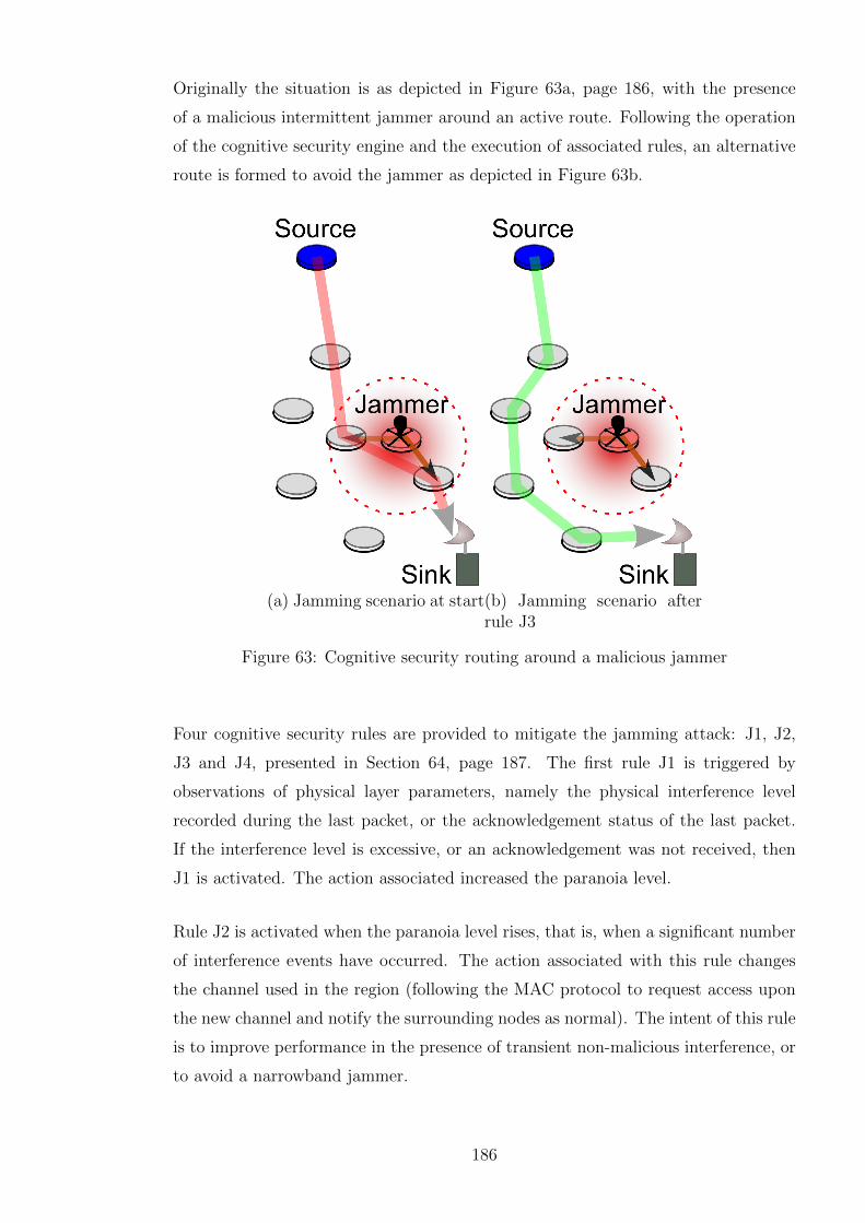
Originally the situation is as depicted in Figure 63a, page 186, with the presence
of a malicious intermittent jammer around an active route. Following the operation
of the cognitive security engine and the execution of associated rules, an alternative
route is formed to avoid the jammer as depicted in Figure 63b.
(a) Jamming scenario at start(b) Jamming scenario afterrule J3
Figure 63: Cognitive security routing around a malicious jammer
Four cognitive security rules are provided to mitigate the jamming attack: J1, J2,
J3 and J4, presented in Section 64, page 187. The first rule J1 is triggered by
observations of physical layer parameters, namely the physical interference level
recorded during the last packet, or the acknowledgement status of the last packet.
If the interference level is excessive, or an acknowledgement was not received, then
J1 is activated. The action associated increased the paranoia level.
Rule J2 is activated when the paranoia level rises, that is, when a significant number
of interference events have occurred. The action associated with this rule changes
the channel used in the region (following the MAC protocol to request access upon
the new channel and notify the surrounding nodes as normal). The intent of this rule
is to improve performance in the presence of transient non-malicious interference, or
to avoid a narrowband jammer.
186

J1: change channel on interference
Trigger: ((phy_interference ()) > MAX_THRESHOLD)
or (mac_ack_status == FAILED)
Actions:
paranoia = paranoia + 0.1;
J2: switch to a different channel
Trigger: (paranoia > CHANGE_THRESHOLD)
Actions:
engage_action PHY_SWITCH_CHANNEL;
J3: engage cross-layer responses
Trigger: (paranoia > DANGER_THRESHOLD)
Actions:
engage_action SEC_REFRESH_KEYS;
engage_action REROUTE_EXCLUDE(current_node);
J4: become less paranoid over time
Trigger: Periodic
Actions:
paranoia = paranoia * FORGET_FACTOR;
Figure 64: Cognitive security for jamming detection
Rule J3 is activated when the paranoia level crosses the next threshold, indicating
that jamming is likely or communications are otherwise disrupted. It triggers two
cross-layer countermeasures, firstly requesting the refreshing of keys in the region.
Given the likely presence of malicious nodes in a region, keys should be discarded
and regenerated, in case existing keys have been compromised or intercepted by
the malicious attackers. The second countermeasure is a routing layer response,
in which the routes crossing this node are refreshed to exclude the present node.
The intent of this is to exclude the node suffering intermittent jamming from data
distribution. Therefore traffic is directed away from this node, and towards safer
areas of the network. If system integrators wished to increase the paranoia of the
system, this approach could be extended to isolate the node and all its peers from
routing, or, if geographic information is available, to isolate an entire region from
routing temporarily or permanently.
Rule J4 is a rule to maintain security state, which decreases paranoia over time. This
rule is always triggered periodically. The associated action multiplies the paranoia
level by a given forgetting factor, which leads to an exponential decrease in the
paranoia level over time. This allows the system to forget isolated suspicious events
over time, which is useful as some failures detected during J1 are likely to be transient
187

interference unrelated to jamming. This rule gives the system more tolerance of
sporadic jamming or delivery failures.
8.3.2 Sybil Node Detection
The scenario for detection of sybil nodes, and associated rules is presented in Figure
65, page 188. The sybil node detection algorithm operates in a hybrid beamforming
network using protocols described in Section 4.5.3, page 90, in which the normal
course of action is to use the distributed beamforming supernode to deliver data
to the sink (Figure 65a). The outcome of the protocol is depicted in Figure 65b,
in which the network falls back to multihop routing when potential sybil nodes
are detected in the beamforming cluster. A multihop route has been formed to
the sink, and the sybil nodes detected by the coordinator by the execution of the
SEC DETECT SYBIL action. The rules presented in Figure 66, page 189 are run
(a) Sybil detection scenario at start
(b) Sybil detection after rule S3
Figure 65: Cognitive security suspending beamforming in the presence of sybil nodes
upon the coordinator of the cluster. Throughout the operation of a beamforming
cluster, rule S1 is invoked whenever the SINR reported from the sink is less than
some critical threshold. In this case, the first response selected is a physical layer
response; changing the channel used for the beamforming transmissions in an attempt
188

S1: check the SINR on receipt of sink messages
Trigger: ((phy_beamforming_sinr() < MIN_SINR)
Actions:
engage_action PHY_CHANGE_BEAMFORM_FREQ
failure_count = failure_count + 1;
S2: begin sybil node detection
Trigger: (failure_count > 3)
Actions:
engage_action SEC_DETECT_SYBILS;
S3: give up beamforming, switch to multihop
delivery
Trigger: (failure_count > 10)
Actions:
engage_action CANCEL_BEAMFORMING;
engage_action ROUTE_TO(sink_id)
failure_count = 0;
Figure 66: Cognitive security rules for handling sybil nodes in beamforming networks
to improve performance. This also updates a state variable of failure count in order
to keep track of how many packets failed in transmission, to use with future rules.
Rule S2 is employed when the number of failures exceeds three. In this case, a sybil
detection algorithm such as radio resource testing (Section 3.3.3.2, page 54) is invoked
to detect sybils in the region, and exclude them from beamforming. This process may
take some time to complete, or may fail to detect the sybils if they mutually vouch
for their fake identities. In the meantime, if the number of failures passes 10, then the
actions of rule S3 are invoked. These actions perform a protocol switch, replacing
beamforming with multihop routing, by cancelling the beamforming process and
removing nodes from their responsibilities under it, and forming a multihop route
to the sink. In this case study the cognitive security engine has acted not just to
increase security but also system performance, by switching to a fallback protocol
after the repeated failure of data delivery.
8.4 Research Issues To Investigate For Cognitive
Security
The architecture as presented in the previous section is capable of solving security
issues according to the fixed rules provided in the orientation. However there are
189

several interesting areas for research on this topic which offer the potential for
productive future work. This section defines four particular areas: varying the rules
assigned to particular nodes, employing collaboration and joint detection, allowing
nodes to learn and modify their own rules in response to changes in circumstances,
and the involvement of human intervention in cognitive security decisions. This
section introduces and discusses these research issues.
8.4.1 Using Paranoid Versus Tolerant Nodes
In the case studies presented above, the nodes have all operated using a common set
of rules, and therefore the behaviour decisions they make will be common. It may
be productive to allow some nodes to be more paranoid than others, for example,
discarding keys earlier than expected, or otherwise changing their behaviour. One
advantage to the use of especially paranoid nodes is that they could serve as sentries
to warn others of potential attack earlier than expected. In addition, making a
proportion of nodes more tolerant of misbehaviour could allow service to continue in
the presence of normal non-malicious failures, which paranoid nodes could reject as
evidence of an attack.
8.4.2 Collaboration Between Nodes
The present architecture for cognitive security makes its decisions entirely based
upon local information, which is a low overhead strategy that does not impose any
distributed communication requirements. By making security decisions locally, it is
also secure against bad-mouthing in which nodes fraudulently claim their neighbours
are malicious. However, it is worth experimenting with adding a level of collaboration
between the cognitive security engines of different nodes. In the previous example
of using paranoid nodes as well as normal nodes, the paranoid nodes could be used
as sentries to warn of potential attacks. Alternatively, allowing nodes to collaborate
over longer distances, and share metrics or other local information, could allow earlier
detection of topology distortion attacks such as the wormhole attack.
190

8.4.3 Self-Modification Of Decision Rules
In the examples provided above, the nodes all follow identical rules, supplied as
part of the orientation phase. However, it is possible using machine learning
techniques for nodes to discover entirely new strategies via their own exploration,
in addition to exploiting the results of past successes. One strategy for this is
reinforcement learning, in which nodes explore multiple behaviours and keep records
of performance. This approach has already been applied to the problem of channel
partitioning in the presence of interference [113]. A reinforcement learning security
engine would track the performance of possible security strategies and reward those
which perform well, for example maintaining continuous delivery, while penalising
those approaches that lead to a reductions in performance metrics: for example,
additional dropped packets.
Other approaches may permit deeper customisation or more flexibility in node
responses. For example, genetic algorithms [114] offer the potential for nodes to
explore different sets of cognitive security rules under an evolutionary framework,
with incremental modification from previous successful strategies and combination
of rules from past successful rule-sets. Over the long term, nodes could evaluate the
fitness of their strategies according to predefined security metrics, such as end-to-end
delivery rate, and discard strategies that appear to impair performance or security.
Under a genetic algorithm framework for cognitive security, nodes would begin with
the decision rules provided by their orientation, but add additional rules to strategies
in response to their environment. The original strategies would be allowed to mutate
and survive if they prove effective in their environment. For example, one node may
decide to change channels periodically, and may retain that rule if it permits it to
stay ahead of potential eavesdropping attacks. Alternatively, if a rule that changes
in response to interference never provides any benefit against potential jamming,
cognitive security engines using a genetic algorithm approach could decide that the
jamming suffered is most likely wideband and eventually delete this rule in favour of
more direct countermeasures.
The ultimate but ambitious goal of this approach is the development of cognitive
security engines that can learn effective responses to novel attacks without human
assistance. It is likely however, given that many attacks will be distributed and
require global knowledge or widespread communication to detect, that cognitive
security research will have to advance incrementally towards this goal.
191
8.4.4 Involvement Of Human Operators
Many sensor networks provide some form of centralised interface upon the sink node
to their human operators, such as the vineyard monitoring system example studied
in the Introduction (Section 2.2.1.2, page 38). It can be envisaged that metadata
on network performance and security will also be highly relevant and of interest
to the operators. For example, the network could report its overall energy status
and aggregate performance condition, in order to warn its operators of any likely
impending failures.
In a similar manner, a cognitive security engine, with its awareness of security-related
state from all across the protocol stack, could give information on security status and
potential security events to the human operators, and allow them to participate in the
decisions. This effectively changes the OODA loop to incorporate human operators
in the decision phases as well as orientation. For example, if new nodes are being
deployed, then the operators could choose to temporarily override any security-
related alerts that may be generated from the topology change. Alternatively,
operators could choose to control directly the system’s level of paranoia. They may
also wish to introduce new decision rules to a subset of nodes, or nodes in certain
regions.
8.5 Conclusion
In order to implement a high-performance WSN capable of handling the security
challenges of the future, it is necessary for the participating nodes to have the
advantage over an attacker in terms of energetics. Rather than the network using
all countermeasures proactively from the beginning of deployment, cognitive security
permits countermeasures to be activated gradually in response to indications that a
threat may exist. This permits the more intelligent usage of energy, together with
a potential to learn responses and define new decision rules. It also permits the
involvement of human operators in security decision making.
Cognitive security presents a future work area for providing flexible and energy-
efficient responses to changing threats, and ultimately for allowing networks to
develop their own countermeasures to novel threats. This chapter has proposed
192

an architecture for its implementation, case studies to illustrate how such a system
would operate and several directions in which research can focus in order to develop
the potential of this emerging field.
193

Chapter 9
Conclusion
Wireless sensor networks offer compelling advantages over manual data gathering,
presenting new opportunities for economically efficient and high-resolution data
gathering. They offer amongst other applications the potential to enable new appli-
cations for environmental monitoring, provide high-resolution analysis of scientific
phenomena, lower costs in logistical tracking, and provide advance warning for
military and border control applications.
However, careful consideration of security threats and potential attacks is required
in order to ensure that systems do not exhibit unintended failure modes. In order for
public acceptance of WSN deployments not to be hindered by malicious attacks and
outside subversion, it is essential to consider the impact of common security threats
upon their data relaying methodologies, and to develop defence in depth in which
routing technologies assist in avoidance of threats within the network.
The analysis of past deployments in the Introduction (Chapter 2) showed that
particular deployments have undergone extensive customisation, with variations in
node capabilities and performance. Examples include the use of heterogeneity for
the XSS aggregation nodes in the ExScal system (Section 2.2.1.3, page 39), or the
backhaul links in the Great Duck Island project (Section 2.2.1.1, page 37). A key
characteristic of these deployment examples is that they contain regions or clusters
of homogeneous nodes, modifying this model as necessary to meet their application
constraints most economically. These deployments have been generally very ad-hoc,
and therefore the security analysis must also be tailored to particular applications.
The thesis has concentrated upon general attacks as referenced in the literature,
as these attacks have been heavily studied by other researchers. However, these
194

attacks and relevant countermeasures have been studied in a variety of representative
topologies to examine the impact of topology variation. Accordingly, the results of
this thesis provide valuable protocol options to consider in the selection of specific
security strategies for a real-world deployment.
The conventional approach to security engineering is to rely upon cryptography for
the protection of message confidentiality and integrity. The energy implications
of public key cryptography generally render it prohibitive for anything other than
bootstrapping other encryption schemes. Lighter weight authentication technologies
such as the one-way hash chain provide an economic way for entities to establish
longer-lasting, authentic relationships. However, a more serious set of objections
to cryptographic schemes is that they cannot protect network availability in the
presence of attacks that modify or distort the topology, such as signal jamming or
the wormhole attack.
The wormhole attack is a troublesome attack to which multihop wireless networks
are vulnerable. In this attack a malicious attacker introduces a pair of nodes with
a heterogeneous link that provides a shortcut across the network, and leads to the
centralisation of routing around its endpoints. By severing the wormhole link at a
convenient time the attacker can abruptly disconnect the network, thus defeating
the redundancy expected by routes across a diverse field of multihop nodes. The
wormhole attack is most likely to be mounted by an attacker with greater resources,
such as heterogeneous antennas and the ability to align them. Wormhole detection
in the literature has explored a variety of approaches, such as timing and direction
analysis via packet leashing, and central topology reconstruction. However, the
difficulties of implementing these in a busy, realistic network motivate an alternative
routing strategy.
The thesis provides two alternative mechanisms for routing-layer avoidance of
potential wormhole attacks, introducing the static and dynamic disturbance-based
routing protocols. Disturbance-based routing provides a complement to the direct
wormhole detection techniques analysed in the Literature Review. In the conven-
tional passive wormhole attack, the static disturbance-based routing protocol can
avoid wormholes based on a local topology property, the peer inflation effect, which
leads to the creation of a strongly connected region around the endpoints. Dynamic
disturbance-based routing by contrast is capable of directing a high proportion of
traffic around even wormholes free of this peer inflation effect, deployed upon the
195

edge of the topology. By routing around the suspected threat locations, data is
directly along safe routes and therefore less likely to encounter the wormhole threat.
The disturbance-based routing strategy is therefore a viable addition to the security
options, assisting in delivering the defence-in-depth strategy favoured in security
engineering.
In many scenarios, the attacker will take time to analyse the structure of the network
and deploy the hardware necessary to launch the wormhole attack. Therefore it can
be expected that there will exist a stabilisation interval during which wormhole-
free routes can be formed. In this situation, reputation-based routing is a viable
alternative, which favours the routes formed early on during network development
and provides stability against the topology changes introduced by the wormhole.
Distributed beamforming is a novel technology which offers the potential to greatly
increase capacity by avoiding the overheads of multihop routing. By using
this distributed physical-layer technology (termed supernodes within the thesis),
nodes collaborate with precisely timed simultaneous transmissions that are received
constructively by a distant sink node. This beamforming architecture also reduces
the requirements of coordination to communicating only with nodes in the local area.
This removes the trust requirement implicit in requiring distant nodes to forward
data, as required by multihop routing. With the likely evolution of oscillators upon
a WSN towards greater phase stability and precision, it offers a potential alternative
data relaying mechanism. This thesis has analysed the security performance against
signal jamming attacks and found that it offers the potential to increase resilience. In
the multihop routing case, a chain of dependencies is created, in which nodes must
sequentially forward packets, resulting in vulnerability to jamming around every
potential candidate receiver. Since jamming is a low-effort attack, particularly when
performed with homogeneous nodes such as the disposable nodes of the network itself,
distributed beamforming relaying offers the ability to secure the network against
jamming by reducing the total areas of vulnerability in the network.
It is likely that distributed beamforming will be integrated as part of a hybrid
approach to support multihop routing, as this approach would only require sporadic
beamforming clusters forming to support the general multihop network. In this
approach physical-reputation based routing protocols (Chapter 7) can be employed
to improve system performance by discovering beamforming clusters with high SINR
performance to use for relaying. The PRBR protocol also provides avoidance of
196

regions subject to the sybil attack, in which malicious nodes increase their influence
by creating additional false identities. Since beamforming success depends on
multiple nodes collaborating successfully, the sybil attack reduces received SINR
since the virtual sybil identities cannot participate in simultaneous transmissions. As
a result, the PRBR protocol which rewards high SINR supernodes, rapidly converges
to avoid supernodes featuring multiple sybil nodes. This sybil avoidance is provided
along with the discovery of routes featuring beamforming clusters which will be most
robust in the presence of link change. Therefore, the sybil avoidance is delivered
alongside a routing feature which improves network performance in the presence of
unreliable beamforming clusters. This is in contrast to the other approaches in the
literature for sybil detection, such as resource testing which requires the injection of
additional traffic, in the form of several iterations with challenge packets in order to
detect the malicious nodes.
Although this thesis has explored techniques for securing data delivery within the
network, a full security analysis considering the likely motivations and sophistication
of any attackers will have to be performed before deployment, taking into account
any unique characteristics of the scenario and its intended usage. If the application
task depends on distributed agreement or aggregation, a sybil attack is likely. If the
attackers are known to have time and resources to activate their own heterogeneous
links and control a region of the topology, wormhole attacks are likely within the
region they control. Performing a full security analysis allows system integrators
to choose the techniques from the thesis to deploy. If a wormhole attack is likely
and the attacker is anticipated to have their attack ready and in operation when
the network is activated, the best strategy would be a disturbance-based routing
protocol. Alternatively, if the network is in a regular topology and will have time to
begin operating first and stabilise upon trusted wormhole-free routes, reputation-
based routing is the best choice. If the sink antennas are available to support
beamforming and nodes are deployed with sufficient density, then PRBR also permits
defence against the sybil attack.
As part of this thorough security analysis, the access network through which data
leaves the WSN will also be an important consideration before deployment. This
thesis has concentrated upon in-network threats affecting the individual wireless
nodes, but a more complete denial of service effect could be achieved, for example,
by severing or interrupting a wired link connecting the network to the monitoring
station. Attacks upon the wireless channel such as signal jamming, and upon
197

the topology such as the wormhole attack, can be mitigated using the techniques
provided in this thesis. However, if an attacker can provide their own insider
within a monitoring or command centre, or can compromise the access link to the
network, then they can disable the system even if the WSN itself is invulnerable
to attack. Therefore, best practices of conventional security engineering must be
followed, including a consideration of the environment surrounding the WSN and
any dependencies it introduces, and an analysis of any threats to which it could be
subject.
However thorough the security analysis, it is not possible to anticipate ahead of
time precisely which attacks will be launched. The Further Work chapter proposes a
remedy in the form of a cognitive security architecture, in which individual nodes scan
the network for potential indications of misbehaviour from all layers of the protocol
stack. As potential indications of misbehaviour change, indicating the likelihood
of attack, nodes engage countermeasures such as changing their data relaying
methodology, rerouting or discarding keys, or running the more energy intensive sybil
detection and wormhole detection strategies mentioned in the Literature Review.
This approach permits some flexibility in the security analysis before deployment, as
the network can adapt the countermeasures it employs to spend its scarce energy in
regions at which a threat is detected.
Therefore, the content of this thesis makes a valuable contribution to security within
WSNs, by providing new approaches that enable defence in depth in the routing
layer to protect against wormhole and sybil attacks, and study of the security
implications of distributed beamforming technologies. Within the context of an
application-specific security analysis, these techniques can form valuable components
of the toolbox of a system integrator or security administrator. The Further Work
chapter also shows how the presented techniques can be extended as part of an
adaptive strategy that integrates them with work by other researchers to meet future
evolving threats, and provide a sensor network engineered to meet the complex design
challenges of the future.
9.1 Novel Contributions
The novel contributions contained in this thesis are summarised below:
198

9.1.1 Supernode and Multihop Routing Vulnerability Anal-ysis
A distributed beamforming (supernode) architecture (Section 4.9, page 101) has been
analysed to determine its vulnerability to the deployment of homogeneous distributed
signal jammers. The supernode scheme has been shown via simulation and analysis to
perform better in the the presence of signal jamming attacks than multihop routing.
9.1.2 Disturbance-Based Routing For Wormhole Avoidance
Two novel routing techniques are introduced, static and dynamic disturbance-based
routing. Static disturbance-based routing is sensitive to connectivity characteristics,
and avoids wormholes as a consequence of the increased connectivity they generate
within the network, and by choosing safer edge routes rather than the shortest path
in which wormholes are more likely to be deployed. Dynamic disturbance-based
routing uses an additional sacrificial route through the shortest path protocol to
discover the wormhole and incentivise the dynamic disturbance-based route away
from it. These techniques have been shown to route away from wormhole attacks
based upon their geometric properties, or by the ongoing traffic patterns that they
introduce under a custom dual-routing protocol. The performance of these schemes
has been analysed under a variety of representative topologies.
9.1.3 Reputation-Based Routing
A novel routing technique, reputation-based routing (RBR) (Section 6.2, page 146)
has been introduced. This protocol is suitable for deployment in networks with
a regular topology, in which an early stabilisation interval exists before wormhole
activation. The protocol logic allows it to successfully avoid wormhole attacks
introduced after this stabilisation interval, via its hysteresis which causes it to favour
previously established routes for future routing following their expiry. Simulation
results have presented favourable avoidance advantage.
199

9.1.4 Physical Reputation-Based Routing
Physical reputation-based routing (PRBR) (Section 7.2, page 159) has been in-
troduced. This protocol integrates with the distributed beamforming (supernode)
architecture described in Section 4.5.3, page 90, and directs multihop routing to
use the best performing supernodes as the final stage for traffic relaying. This
provides a viable approach for avoiding the sybil attack in WSNs, given the reduction
in beamforming performance they generate. Simulation results are presented to
demonstrate the performance of the PRBR protocol.
200

Definitions
ADV Avoidance Advantage
AODV Ad-Hoc On-Demand Distance Vector
CBC-MAC Cipher Block Chaining Message Authentication Code
CBC Cipher Block Chaining
CPU Central Processing Unit
DARPA Defence Advanced Projects Research Agency
DDHC Dual Directional Hash Chains
DDYN Dynamic disturbance metric
DID Defence In Depth
DSSS Direct Sequence Spread Spectrum
DoS Denial of Service
ECB Electronic Code Book
ECC Elliptic Curve Cryptography
GPS Global Positioning System
IEEE Institute of Electrical and Electronics Engineers
INSENS Intrusion-Tolerant Routing Protocol For Wireless Sensor Networks
ISM Industrial, Scientific and Medical
JTAG Joint Test Action Group
LEAP Localised Encryption and Authentication Protocol
201

MAC Media Access Control
MEMS Micro-Electro-Mechanical Systems
µ-TESLA µ-Timed Efficient Stream Loss-Tolerant Authentication
MoD Ministry of Defence
O-QPSK Offset Quaternary Phase Shift Keying
OHC One-Way Hash Chain
OLSR Optimised Link State Routing
OSI Open System Interconnection
PIR Passive Infra Red
PKI Public Key Infrastructure
PRBR-RREP Physical Reputation-Based Routing Route Reply
PRBR-RREQ Physical Reputation-Based Routing Route Request
PRBR Physical Reputation-Based Routing
PSD Power Spectral Density
QoS Quality of Service
RBR-RREP Reputation-Based Routing Route Reply
RBR-RREQ Reputation-Based Routing Route Request
RBR Reputation-Based Routing
RLEVEL INC Reputation Level Increment
RLEVEL Reputation Level
RM Reputation Metric
RNK Reputation Null Constant
RSA Rivest, Shamir and Adleman
RTT Round Trip Time
SAM Statistical Analysis of Multipath
202

SDYN Static disturbance metric
SECTOR Secure Tracking of Node Encounters
SINR Signal to Interference and Noise Ratio
SNEP Sensor Network Encryption Protocol
SNM Supernode Members
SPAF Shortest Path Activity Factor
TDMA Time Division Multiple Access
TTL Time To Live
USB Universal Serial Bus
VANET Vehicular Ad-Hoc Networks
WSN Wireless Sensor Network
XOR Exclusive OR
XSM eXtreme Scale Motes
XSS eXtreme Scale Stargate
203

Glossary
ADV - (Avoidance Advantage) A success metric for wormhole avoidance
protocols; the additional proportion of all discovered routes that successfully avoid
the wormhole under disturbance-based routing, compared to under shortest path
AODV - (Ad-Hoc On-Demand Distance Vector) A well-established and
commonly studied reactive routing protocol which can be adapted to use other
metrics in addition to shortest path
CBC-MAC - (Cipher Block Chaining Message Authentication Code) A
way of using the Cipher Block Chaining mode of a fixed-length block cipher in
order to compute an integrity protection (MAC) code which depends upon an entire
arbitrary-length message
CBC - (Cipher Block Chaining) The sequential execution of an encryption
algorithm upon separate blocks of a longer message, such that encryption of previous
blocks is used as an input to a current block
CPU - (Central Processing Unit) The core of a embedded or desktop computer,
responsible for computation and interfacing with memory and input/output devices
through interrupts and system buses
DARPA - (Defence Advanced Projects Research Agency) A US military
research agency responsible for some fundamental networking and early sensor
network research
204

DDHC - (Dual Directional Hash Chains) A pair of one-way hash chains
(OHCs) operated simultaneously in alternative directions, allowing interactions at
unique time windows to be established
DDYN - (Dynamic disturbance metric) The metric value computed in
dynamic disturbance-based routing protocols, calculated from the shortest-path
activity factor (SPAF) at the source node and a basis value β
DID - (Defence In Depth) The use of a layered set of independent countermea-
sures supporting a single system feature, to increase the minimal work the attacker
must perform for a successful compromise
DSSS - (Direct Sequence Spread Spectrum) A transmission method which
increases the transmission rate by using a spreading code, so as to expand the
bandwidth of a signal and hide it beneath the noise floor
DoS - (Denial of Service) An attack in which a malicious entity attempts to
disable a system and remove temporarily or permanently the functionality it provides
ECB - (Electronic Code Book) A simple encryption scheme involving the
division of a message into fixed-sized blocks which are encrypted independently
ECC - (Elliptic Curve Cryptography) A public-key cryptosystem built upon
the mathematical entity elliptic curves, which have advantageous properties for
energy usage at a low modulus compared to other public-key system
GPS - (Global Positioning System) A system for accurate localisation of
devices (and accurate time-keeping upon them) supported by satellites
IEEE - (Institute of Electrical and Electronics Engineers) A professional
organisation responsible, amongst other activities, for engineering research, publica-
tion and standardisation
205

INSENS - (Intrusion-Tolerant Routing Protocol For Wireless Sensor
Networks) A secure routing protocol built upon proactive link-state routing in
which messages are authenticated by one-way hash chains and the topology centrally
computed
ISM - (Industrial, Scientific and Medical) Radio transmission bands allowing
license-free operation commonly employed in wireless sensor and ad-hoc network
research
JTAG - (Joint Test Action Group) A standardised approach for in-circuit
debugging of electronic systems with embedded processors or microcontrollers
LEAP - (Localised Encryption and Authentication Protocol) A key
management architecture which features a hierarchy with multiple keys at different
geographic levels
MAC - (Media Access Control) A sub-task of the data link layer in the OSI
model, which involves managing access to a shared communications medium by
multiple devices
MEMS - (Micro-Electro-Mechanical Systems) A micro-scale technology for
extremely small physical technology such as sensors and actuators, which can be
used in developing extremely small sensor nodes
µ-TESLA - (µ-Timed Efficient Stream Loss-Tolerant Authentication) A
lightweight protocol which allows multicast streams to be delivered, for example from
the sink to all nodes
MoD - (Ministry of Defence) The UK body for military strategy development,
forces management, resource allocation and technology development
206

O-QPSK - (Offset Quaternary Phase Shift Keying) A modulation scheme
providing two bits per symbol, in which the constellation points are rotated π/2
radians from standard QPSK
OHC - (One-Way Hash Chain) A lightweight scheme for authentication based
upon a hash function, allowing an entity such as a sink to prove itself as authentic
by releasing values that hash to a pre-released value
OLSR - (Optimised Link State Routing) A routing protocol which continu-
ously scans adjacent peers for link connectivity and propagates this link information
throughout the topology to allow routing
OSI - (Open System Interconnection) A model for characterising communi-
cation in terms of a hierarchy of abstract layers, communicating with their adjacent
neighbours to separate protocol functions
PIR - (Passive Infra Red) A sensory device which detects heat emissions from
an object in its field of view
PKI - (Public Key Infrastructure) Security architectures involving public-key
cipher schemes and associated key establishment and management operations
PRBR-RREP - (Physical Reputation-Based Routing Route Reply) The
response packet sent from the sink to the nodes along the reverse direction of the
best candidate route
PRBR-RREQ - (Physical Reputation-Based Routing Route Request)
The request packet broadcast by nodes to the sink in physical reputation-based
routing (PRBR), in order to trigger route formation
207

PRBR - (Physical Reputation-Based Routing) A reputation-based routing
approach covered in Chapter 7 which is sensitive to physical-layer SINR of relaying
beamforming supernodes and thus avoids sybil attacks
PSD - (Power Spectral Density) The density of instantaneous energy in the
frequency domain, used in spectral analysis of a signal
QoS - (Quality of Service) A characteristic of communication systems regarding
guarantees of a certain level of performance, for example limits to latency (transmis-
sion time) or bandwidth demand
RBR-RREP - (Reputation-Based Routing Route Reply) The response
packet sent from the sink to the nodes along the reverse direction of the best
candidate route
RBR-RREQ - (Reputation-Based Routing Route Request) The request
packet broadcast by nodes to the sink in reputation-based routing (PRBR), in order
to trigger route formation
RBR - (Reputation-Based Routing) A reputation-based routing approach
which is suitable for the avoidance of late-established wormholes
RLEVEL INC - (Reputation Level Increment) The magnitude of the incre-
ment in reputation-based routing (RBR), computed from the bandwidth demand of
an individual route and the channel capacity
RLEVEL - (Reputation Level) The reputation level recorded in RBR or PRBR
and incremented at nodes upon a favourable route to indicate favouring of this node
in future
208

RM - (Reputation Metric) The metric value computed logarithmically from
the reputation level (RLEVEL) and aggregated along a route to establish its overall
quality
RNK - (Reputation Null Constant) A constant value for the reputation metric
when reputation levels are zero, therefore an initialisation value for the routing metric
RSA - (Rivest, Shamir and Adleman) A public key encryption algorithm
involving modular exponents, featuring a secret key used for encryption and a public
key which can be published
RTT - (Round Trip Time) The time taken for a reply to reach a remote endpoint
and for a response to be received back from the original recipient
SAM - (Statistical Analysis of Multipath) An approach to detect wormholes
by the statistical properties of multipath routes formed
SDYN - (Static disturbance metric) The metric value computed in static
disturbance-based routing from the peer count at the transmitting node, and an
exponent α
SECTOR - (Secure Tracking of Node Encounters) A protocol for tracking
node encounters and securely establishing the time of interactions between nodes
using hash chains
SINR - (Signal to Interference and Noise Ratio) A measure of the strength
of the intended signal relative to the combination of interfering signals from other
transmitters and environmental radio noise
SNEP - (Sensor Network Encryption Protocol) A link-layer protocol for use
in sensor networks, deriving separate encryption keys for confidentiality and integrity
protection
209

SNM - (Supernode Members) Sensor nodes which participate in distributed
beamforming in support of a coordinator which manages the beamforming process
SPAF - (Shortest Path Activity Factor) A dynamic parameter for dynamic
disturbance-based routing, incremented in response to shortest path traffic passing
through this node
TDMA - (Time Division Multiple Access) The separation of multiple
contenting transmissions into different time allocations (such as slots) to avoid
mutual interference from the devices
TTL - (Time To Live) A timing countdown applied to network packets to prevent
routing loops, decremented at each intermediate forwarding point, and causing
packet deletion when it expires
USB - (Universal Serial Bus) A standard for serial communication between a
host, such as a developer’s computer, and several devices, such as sensor nodes or
storage devices
VANET - (Vehicular Ad-Hoc Networks) Networks comprised of vehicles such
as cars and buses, and associated roadside equipment, or using vehicles for the
relaying of traffic-related data
WSN - (Wireless Sensor Network) A distributed network of sensory and
communication nodes, which conventionally have limited energy resources and
communicate to perform sensing and relaying of sensed data
XOR - (Exclusive OR) A multiple-input boolean logic operation which outputs
true if any of its inputs are true, but false if all or none of them are true
XSM - (eXtreme Scale Motes) The lowest level individual sensory device in
the ExScal (Extreme Scale) wireless sensor network system
210

XSS - (eXtreme Scale Stargate) The aggregation level of the ExScal system,
which manages communications from multiple lower-level nodes (XSMs)
211
Bibliography
[1] J. Harbin, P. Mitchell, and D. Pearce, Security Of Self-Organizing Networks:
MANET, WSN, WMN, VANET - Secure Routing Architectures Using Cross
Layer Information for Attack Avoidance: With Case Study on Wormhole
Attacks, ch. 19, pp. 465–492. Taylor and Francis Group (CRC Press), 1st ed.,
Dec. 2010.
[2] J. Harbin, P. Mitchell, and D. Pearce, Wireless sensor network wormhole avoid-
ance using disturbance-based routing schemes in ISWCS 2009: Proceedings
of the Sixth International Symposium On Wireless Communication Systems,
(Piscataway, NJ, USA), pp. 76–80, IEEE Press, Sept. 2009.
[3] J. Harbin, P. Mitchell, and D. Pearce, Wireless sensor network wormhole avoid-
ance using reputation-based routing in ISWCS 2010: Seventh International
Symposium on Wireless Communication Systems, pp. 521 –525, Sept. 2010.
[4] J. Harbin and P. Mitchell, Reputation Routing To Avoid Sybil Attacks
In Wireless Sensor Networks Using Distributed Beamforming ISWCS 2011:
Eighth International Symposium on Wireless Communication Systems, Nov.
2011.
[5] R. Lacoss, Strawman Design of a DSN (Distributed Sensors Networks) to
Detect and Track Low Flying Aircraft in Proceedings of the Distributed Sensor
Nets Workshop, pp. 41–52, Dec. 1978.
[6] H. Abelson, D. Allen, D. Coore, C. Hanson, G. Homsy, J. Thomas F. Knight,
R. Nagpal, E. Rauch, G. J. Sussman, and R. Weiss, Amorphous computing
Communications of The ACM, vol. 43, pp. 74–82, May 2000.
[7] R. Jedermann, C. Behrens, D. Westphal, and W. Lang, Applying autonomous
sensor systems in logistics–Combining sensor networks, RFIDs and software
agents Sensors and Actuators A: Physical, vol. 132, pp. 370–375, Nov. 2006.
212
[8] L. Schwiebert, S. K. S. Gupta, and J. Weinmann, Research Challenges in
Wireless Networks of Biomedical Sensors in ACM MOBICOM: Proceedings
of the Seventh Annual International Conference on Mobile Computing and
Networking, pp. 151–165, ACM, July 2001.
[9] W. Hu, N. Bulusu, C. T. Chou, S. Jha, A. Taylor, and V. N. Tran, Design and
evaluation of a hybrid sensor network for cane toad monitoring TOSN: ACM
Transactions on Sensor Networks, vol. 5, pp. 4:1–4:28, Feb. 2009.
[10] A. Mainwaring, D. Culler, J. Polastre, R. Szewczyk, and J. Anderson, Wireless
sensor networks for habitat monitoring in WSNA ’02: 1st ACM International
Workshop On Wireless Sensor Networks and Applications, (New York, NY,
USA), pp. 88–97, ACM, 2002.
[11] S. H. Lee, S. Lee, H. Song, and H. S. Lee, Wireless sensor network design for
tactical military applications: Remote large-scale environments in MILCOM
2009: IEEE Military Communications Conference, pp. 1–7, IEEE, Oct. 2009.
[12] G. Simon, M. Maroti, A. Ledeczi, G. Balogh, B. Kusy, A. Nadas, G. Pap,
J. Sallai, and K. Frampton, Sensor network-based countersniper system in
SenSys 2004: Proceedings of the 2nd International Conference on Embedded
Networked Sensor Systems, (New York, NY, USA), pp. 1–12, ACM, Nov. 2004.
[13] I. Akyildiz, W. Su, Y. Sankarasubramaniam, and E. Cayirci, A survey on
sensor networks IEEE Communications Magazine, vol. 40, pp. 102–114, Aug.
2002.
[14] J. Yick, B. Mukherjee, and D. Ghosal, Wireless sensor network survey
Computer Networks, vol. 52, no. 12, pp. 2292–2330, 2008. Elsevier B.V.
[15] K. Romer and F. Mattern, The design space of wireless sensor networks IEEE
Wireless Communications, vol. 11, pp. 54–61, Dec. 2004.
[16] J. Hill, M. Horton, R. Kling, and L. Krishnamurthy, The platforms enabling
wireless sensor networks Communications of the ACM, vol. 47, pp. 41–46, June
2004.
[17] M. Yarvis, N. Kushalnagar, H. Singh, A. Rangarajan, Y. Liu, and S. Singh,
Exploiting heterogeneity in sensor networks IEEE INFOCOM: 24th Annual
Joint Conference of the IEEE Computer and Communications Societies, vol. 2,
pp. 878–890, Mar. 2005.
213

[18] R. Stoleru, J. A. Stankovic, and S. H. Son, Robust node localization for wireless
sensor networks in EmNets ’07: Proceedings of the 4th Workshop on Embedded
Networked Sensors, (New York, NY, USA), pp. 48–52, ACM, 2007.
[19] E. Gaura, L. Girod, J. Brusey, M. Allen, and G. Challen, Wireless Sensor
Networks: Deployments and Design Frameworks. 236 Gray’s Inn Road, Floor
6, London, WC1X 8HB, UK: Springer Verlag, first ed., 2010.
[20] G. E. Moore, Cramming more components onto integrated circuits Electronics
Magazine, vol. 8, Apr. 1965.
[21] S. Borkar, Getting Gigascale Chips: Challenges and Opportunities in Contin-
uing Moore’s Law ACM Queue, vol. 1, pp. 26–33, Oct. 2003.
[22] F. Sebastiano, L. J. Breems, K. Makinwa, S. Drago, D. Leenaerts, and
B. Nauta, A low-voltage mobility-based frequency reference for crystal-less
ULP radios IEEE Journal of Solid-State Circuits, vol. 44, pp. 2002–2009, July
2009.
[23] “Mica2 wireless measurement system datasheet.” http://bullseye.xbow.
com:81/Products/Product_pdf_files/Wireless_pdf/MICA2_Datasheet.
pdf, Crossbow Technology, Inc., 2005. Doc No 6020-0042-08 Rev A.
[24] “Micaz wireless measurement system datasheet.” http://bullseye.xbow.
com:81/Products/Product_pdf_files/Wireless_pdf/MICAz_Datasheet.
pdf, Crossbow Technology, Inc., 2006. Doc No 6020-0060-08 Rev A.
[25] P. Levis, S. R. Madden, J. Polastre, R. Szewczyk, K. Whitehouse, A. Woo,
D. Gay, J. Hill, M. Welsh, and E. Brewer, TinyOS: An Operating System for
Sensor Networks Ambient Intelligence, vol. 35, pp. 115–148, 2005. Springer
Verlag.
[26] Wireless medium access control and physical layer specifications for low-rate
wireless personal area networks IEEE Standard 802.15.4-2003, IEEE, May
2003.
[27] JN-DS-JN5148-1v6 Data Sheet Tech. Rep. JN-DS-JN5148-1v6, Jennic (NXP
Semiconductors), 2010.
[28] M. Gad-el Hak, ed., The MEMS Handbook. CRC Press (Taylor and Francis
Group), second edition ed., Dec. 2005.
214

[29] S. Roundy, P. K. Wright, and J. M. Rabaey, Energy scavenging for wireless
sensor networks: with special focus on vibrations. Springer Netherlands, Nov.
2003.
[30] International Telecommunications Union (ITU-T), Recommendation X.200
(07/94): Open Systems Interconnection - Basic Reference Model, July 1994.
[31] I. Demirkol, C. Ersoy, and F. Alagoz, MAC protocols for wireless sensor
networks: a survey IEEE Communications Magazine, vol. 44, pp. 115–121,
Apr. 2006.
[32] J. Hill, R. Szewczyk, A. Woo, S. Hollar, D. Culler, and K. Pister, System
architecture directions for networked sensors ACM SIGPLAN Notices, vol. 35,
pp. 93–104, Nov. 2000.
[33] P. Gupta and P. R. Kumar, The capacity of wireless networks IEEE Transac-
tions on Information Theory, vol. 46, pp. 388–404, Mar. 2000.
[34] T. Melodia, M. Vuran, and D. Pompili, The State of the Art in Cross-
Layer Design for Wireless Sensor Networks in Wireless Systems and Network
Architectures in Next Generation Internet (M. Cesana and L. Fratta, eds.),
vol. 3883 of Lecture Notes in Computer Science, pp. 78–92, Springer Berlin,
2006.
[35] P. Skraba, H. Aghajan, and A. Bahai, Cross-Layer Optimization for High
Density Sensor Networks: Distributed Passive Routing Decisions in Ad-Hoc,
Mobile, and Wireless Networks (I. Nikolaidis, M. Barbeau, and E. Kranakis,
eds.), vol. 3158 of Lecture Notes in Computer Science, pp. 630–644, Springer
Berlin, 2004.
[36] S. Biswas and R. Morris, ExOR: opportunistic multi-hop routing for wireless
networks SIGCOMM Computer Communications Review, vol. 35, pp. 133–144,
Aug. 2005.
[37] S. Cui, R. Madan, A. Goldsmith, and S. Lall, Joint routing, MAC, and link
layer optimization in sensor networks with energy constraints in ICC 2005:
IEEE International Conference on Communications, vol. 2, pp. 725–729, IEEE,
May 2005.
215

[38] J. Burrell, T. Brooke, and R. Beckwith, Vineyard computing: Sensor networks
in agricultural production IEEE Pervasive Computing, vol. 3, no. 1, pp. 38–45,
2004.
[39] A. Arora, R. Ramnath, E. Ertin, P. Sinha, S. Bapat, V. Naik, V. Kulathumani,
H. Zhang, H. Cao, M. Sridharan, S. Kumar, N. Seddon, C. Anderson,
T. Herman, N. Trivedi, C. Zhang, M. Nesterenko, R. Shah, S. Kulkarni,
M. Aramugam, L. Wang, M. Gouda, Y.-r. Choi, D. Culler, P. Dutta,
C. Sharp, G. Tolle, M. Grimmer, B. Ferriera, and K. Parker, ExScal: Elements
of an Extreme Scale Wireless Sensor Network RTCSA 2005: 11th IEEE
International Conference on Embedded and Real-Time Computing Systems and
Applications, vol. 0, pp. 102–108, Aug. 2005.
[40] Y. Choi, M. G. Gouda, H. Zwang, and A. Arora, Routing on a logical grid
in sensor networks Tech. Rep. TR-04-49, Computer Science Department, The
University of Texas, Austin, Texas USA, 2004.
[41] C. Karlof, N. Sastry, and D. Wagner, TinySec: a link layer security architecture
for wireless sensor networks in SenSys 2004: Proceedings of the 2nd Interna-
tional Conference on Embedded Networked Sensor Systems, (New York, NY,
USA), pp. 162–175, ACM, Nov. 2004.
[42] C. Karlof and D. Wagner, Secure routing in wireless sensor networks: attacks
and countermeasures Ad Hoc Networks, vol. 1, no. 2-3, pp. 293–315, 2003.
[43] A. Burr, T. Clarke, D. Chen, J. Chen, Y. Deng, D. Grace, B. Han,
P. Likitthanasate, Y. Liu, P. Mitchell, D. Pearce, A. Pomfret, and
Y. Wang, Cognitive Routing for Tactical Ad Hoc Networks Tech. Rep.
UOY/MODCOI/B990/FR/1, UK Ministry of Defence, Sept. 2008.
[44] R. Riem-Vis, Cold Chain Management using an Ultra Low Power Wireless
Sensor Network WAMES: Workshop on Applications of Mobile Embedded
Systems, 2004.
[45] M. Nekovee, Sensor networks on the road: the promises and challenges of
vehicular ad hoc networks and grids in Workshop on Ubiquitous Computing
and e-Research, 2005.
[46] P. Juang, H. Oki, Y. Wang, M. Martonosi, L. S. Peh, and D. Rubenstein,
Energy-efficient computing for wildlife tracking: design tradeoffs and early
216

experiences with ZebraNet ACM SIGPLAN Notices, vol. 37, pp. 96–107, Oct.
2002.
[47] R. Anderson, Security engineering. Wiley New York, 2001.
[48] M. Stamp, Information Security: Principles and Practice, ch. 8, pp. 195–196.
John Wiley and Sons, Inc., first ed., 2005.
[49] R. Roman, J. Zhou, and J. Lopez, On the security of wireless sensor networks
Proc. Int. Conference on Computational Science and its Applications (ICCSA
2005), LNCS, vol. 3482, pp. 681–690, 2005.
[50] B. Randell, P. Lee, and P. C. Treleaven, Reliability Issues in Computing System
Design CSUR: ACM Computing Surveys, vol. 10, pp. 123–165, June 1978.
[51] J. W. Hui and D. Culler, The dynamic behavior of a data dissemination
protocol for network programming at scale in SenSys 2004: Proceedings of the
2nd International Conference on Embedded Networked Sensor Systems, (New
York, NY, USA), pp. 81–94, ACM, Nov. 2004.
[52] N. R. Prasad and M. Alam, Security framework for wireless sensor net-
works Wireless Personal Communications, vol. 37, no. 3, pp. 455–469, 2006.
10.1007/s11277-006-9044-7.
[53] S. Marti, T. J. Giuli, K. Lai, and M. Baker, Mitigating routing misbehavior
in mobile ad hoc networks in ACM MobiCom 2000: Proceedings of the 6th
International Conference on Mobile Computing and Networking, pp. 255–265,
ACM, 2000.
[54] J. Clulow and T. Moore, Suicide for the common good: a new strategy
for credential revocation in self-organizing systems ACM SIGOPS Operating
Systems Review, vol. 40, no. 3, pp. 18–21, 2006.
[55] J. Douceur, The Sybil Attack in Peer-to-Peer Systems (P. Druschel,
F. Kaashoek, and A. Rowstron, eds.), vol. 2429 of Lecture Notes in Computer
Science, pp. 251–260, Springer Berlin, 2002.
[56] J. Newsome, E. Shi, D. Song, and A. Perrig, The sybil attack in sensor
networks: analysis and defenses pp. 259–268, ACM, 2004.
[57] B. N. Levine, C. Shields, and N. B. Margolin, A Survey of Solutions to the
Sybil Attack tech report, University of Massachusetts Amherst, MA, 2006.
217

[58] C. Piro, C. Shields, and B. N. Levine, Detecting the Sybil Attack in Mobile
Ad hoc Networks in IEEE Securecomm: Third International Conference on
Security and Workshops, pp. 1–11, Aug. 2006.
[59] F. Stajano and R. Anderson, The Resurrecting Duckling: Security Issues for
Ad-hoc Wireless Networks IEEE Computer, vol. 35, no. 4, pp. 22–26, 2002.
[60] Y. C. Hu, A. Perrig, and D. B. Johnson, Packet leashes: a defense against
wormhole attacks in wireless networks vol. 3, pp. 1976–1986, Apr. 2003.
[61] D. Liu, P. Ning, A. Liu, C. Wang, and W. K. Du, Attack-Resistant Location
Estimation in Wireless Sensor Networks ACM Transactions on Information
and System Security, vol. 11, pp. 1–39, July 2008.
[62] L. Hu and D. Evans, Using directional antennas to prevent wormhole attacks
in Network and Distributed System Security Symposium (NDSS), pp. 131–141,
The Internet Society, Feb. 2004.
[63] R. Poovendran and L. Lazos, A graph theoretic framework for preventing the
wormhole attack in wireless ad hoc networks Wireless Networks, vol. 13, pp. 27–
59, Jan. 2007.
[64] W. Wang and B. Bhargava, Visualization of wormholes in sensor networks
in WiSe 2004: Proceedings of the 3rd ACM Workshop on Wireless Security,
pp. 51–60, ACM New York, NY, USA, Oct. 2004.
[65] L. Qian, N. Song, and X. Li, Detection of wormhole attacks in multi-path
routed wireless ad hoc networks: a statistical analysis approach Journal Of
Network and Computer Applications, vol. 30, pp. 308–330, Jan. 2007.
[66] M. A. Gorlatova, M. Kelly, R. Liscano, and P. C. Mason, Enhancing
frequency-based wormhole attack detection with novel jitter waveforms in
IEEE Securecomm: Third International Conference on Security and Work-
shops, pp. 304–309, Sept. 2007.
[67] P. Jacquet, P. Muhlethaler, T. Clausen, A. Laouiti, A. Qayyum, and L. Vien-
not, Optimized link state routing protocol for ad hoc networks in INMIC 2001:
IEEE International Multi Topic Conference - Technology for the 21st Century,
pp. 62–68, Dec. 2001.
[68] J. Daemen and V. Rijmen, The design of Rijndael: AES–the advanced
encryption standard. Springer Verlag, 2002.
218

[69] Public Key Cryptography Standards (PKCS) No 1 V2.1: RSA CRYPTOG-
RAPHY STANDARD Standard No 1. V2.1, RSA Data Security Inc, RSA
Laboratories, 174 Middlesex Turnpike, Bedford, MA 01730 USA, June 2002.
[70] W. Diffie and M. Hellman, New directions in cryptography in IEEE Transac-
tions on Information Theory, vol. 22, pp. 644–654, Nov. 1976.
[71] N. Koblitz, Elliptic curve cryptosystems Mathematics of Computation, vol. 48,
no. 177, pp. 203–209, 1987.
[72] V. S. Miller, Use of elliptic curves in cryptography CRYPTO 85 Proceedings:
Advances in Cryptology, pp. 417–426, 1986.
[73] A. Perrig, J. A. Stankovic, and D. Wagner, Security in wireless sensor networks
Communications of the ACM, vol. 47, no. 6, pp. 53–57, 2004.
[74] A. Perrig, R. Szewczyk, J. Tygar, V. Wen, and D. Culler, SPINS: Security
Protocols for Sensor Networks Wireless Networks, vol. 8, no. 5, pp. 521–534,
2002.
[75] R. Watro, D. Kong, S.-f. Cuti, C. Gardiner, C. Lynn, and P. Kruus, TinyPK:
securing sensor networks with public key technology in SASN ’04: Proceedings
of the 2nd ACM workshop on Security of ad hoc and sensor networks, (New
York, NY, USA), pp. 59–64, ACM, 2004.
[76] D. Malan, M. Welsh, and M. Smith, A public-key infrastructure for key
distribution in TinyOS based on elliptic curve cryptography IEEE SECON
2004: First Annual IEEE Communications Society Conference on Sensor and
Ad Hoc Communications and Networks., pp. 71–80, Oct. 2004.
[77] K. Piotrowski, P. Langendoerfer, and S. Peter, How public key cryptography
influences wireless sensor node lifetime in SASN ’06: Proceedings of the fourth
ACM workshop on Security of ad hoc and sensor networks, (New York, NY,
USA), pp. 169–176, ACM, 2006.
[78] L. Lamport, Password authentication with insecure communication Commu-
nications of the ACM, vol. 24, no. 11, pp. 770–772, 1981.
[79] S. Capkun, L. Buttyan, and J.-P. Hubaux, SECTOR: secure tracking of node
encounters in multi-hop wireless networks in SASN ’03: Proceedings of the 1st
ACM workshop on Security of ad hoc and sensor networks, (New York, NY,
USA), pp. 21–32, ACM, 2003.
219

[80] Y. Jiang, C. Lin, M. Shi, and X. Shen, Self-healing group key distribution with
time-limited node revocation for wireless sensor networks Ad Hoc Networks,
vol. 5, no. 1, pp. 14–23, 2007.
[81] L. Eschenauer and V. D. Gligor, A key-management scheme for distributed
sensor networks in CCS ’02: Proceedings of the 9th ACM conference on
Computer and communications security, (New York, NY, USA), pp. 41–47,
ACM, 2002.
[82] S. Zhu, S. Setia, and S. Jajodia, LEAP: efficient security mechanisms for large-
scale distributed sensor networks in CCS ’03: Proceedings of the 10th ACM
conference on Computer and communications security, (New York, NY, USA),
pp. 62–72, ACM, 2003.
[83] A. Perrig, R. Canetti, J. Tygar, and D. Song, Efficient authentication and
signing of multicast streams over lossy channels IEEE Symposium on Security
and Privacy, vol. 5, 2000.
[84] J. Deng, R. Han, and S. Mishra, INSENS: Intrusion-tolerant routing for
wireless sensor networks Computer Communications, vol. 29, no. 2, pp. 216–
230, 2006.
[85] M. Bellare, J. Kilian, and P. Rogaway, The security of the cipher block chaining
message authentication code Journal of Computer and System Sciences,
vol. 61, pp. 362–399, Dec. 2000.
[86] I. F. Akyildiz, D. Pompili, and T. Melodia, Underwater acoustic sensor
networks: research challenges Ad Hoc networks, vol. 3, pp. 257–279, May 2005.
[87] B. Warneke, M. Last, B. Liebowitz, and K. Pister, Smart Dust: communicating
with a cubic-millimeter computer IEEE Computer, vol. 34, pp. 44–51, Jan.
2001.
[88] J. A. Stankovic, Research challenges for wireless sensor networks ACM
SIGBED Review, vol. 1, pp. 9–12, 2004.
[89] S. Tilak, Towards A Holistic Approach for Protocol Development in Sensor
Networks. PhD thesis, State University of New York, 2005.
[90] M. Ringwald, K. Romer, and A. Vitaletti, Passive Inspection Of Sensor
Networks Distributed Computing in Sensor Systems, vol. Lecture Notes In
Computer Science, no. 4549, pp. 205–222, 2007.
220

[91] S. E. Ha, S. Choi, B. Song, and H. S. Lee, A new data propagation scheme
for WSN network reprogramming in a noise-full environments in ICOIN:
International Conference on Information Networking, pp. 547 –552, Jan. 2011.
[92] E. Chailloux, P. Manoury, and B. Pagano, Developing Applications With
Objective Caml. O’Reilly France, 2000.
[93] T. S. Rappaport, Wireless Communications: Second Edition, ch. 4, pp. 120–
125. Upper Saddle River, NJ 07458: Prentice Hall PTR, 2002.
[94] T. S. Rappaport, Wireless communications: Principles and Practice. Prentice
Hall, second ed., Jan. 2002.
[95] A. Martinez-Sala, J. M. Molina-Garcia-Pardo, E. Egea-Lopez, J. Vales-Alonso,
L. Juan-Llacer, and J. Garcia-Haro, An Accurate Radio Channel Model
for Wireless Sensor Networks Simulation Journal of Communications and
Networks, vol. 7, Dec. 2005.
[96] T. Moscibroda, R. Wattenhofer, and Y. Weber, Protocol Design Beyond
Graph-Based Models Proceedings of the 5th ACM SIGCOMM Workshop on
Hot Topics in Networks (HotNets), 2006.
[97] H. Ochiai, P. Mitran, H. V. Poor, and V. Tarokh, Collaborative beamforming
for distributed wireless ad hoc sensor networks IEEE Transactions on Signal
Processing, vol. 53, pp. 4110–4124, Nov. 2005.
[98] R. Mudumbai, D. Brown, U. Madhow, and H. V. Poor, Distributed transmit
beamforming: challenges and recent progress IEEE Communications Maga-
zine, vol. 47, no. 2, pp. 102–110, 2009.
[99] Energy Savings from Implementing Collaborative Beamforming for a Remote
Low Power Wireless Sensor Network in AusWireless (International conference
on Wireless Broadband and Ultra Wideband Communication), Mar. 2006.
[100] D. Brown and H. V. Poor, Time-slotted round-trip carrier synchronization
for distributed beamforming IEEE Transactions on Signal Processing, vol. 56,
no. 11, pp. 5630–5643, 2008.
[101] Y. Deng, A. Burr, D. Pearce, and D. Grace, Distributed beamforming for cog-
nitive radio networks in Third International Conference on Communications
and Networking in China - ChinaCom, pp. 1206–1210, Nov. 2008.
221

[102] Y.-S. Tu and G. J. Pottie, Coherent cooperative transmission from multiple
adjacent antennas to a distant stationary antenna through AWGN channels in
VTC 2002: IEEE 55th Vehicular Technology Conference, vol. 1, pp. 130 – 134,
Aug. 2002.
[103] I. Brown, D.R., G. B. Prince, and J. A. McNeill, A method for carrier frequency
and phase synchronization of two autonomous cooperative transmitters in
IEEE 6th Workshop on Signal Processing Advances in Wireless Communi-
cations, pp. 260 – 264, June 2005.
[104] W. B. Heinzelman, A. P. Chandrakasan, and H. Balakrishnan, An application-
specific protocol architecture for wireless microsensor networks Wireless Com-
munications, IEEE Transactions on, vol. 1, pp. 660 – 670, oct 2002.
[105] M. Haenggi, A. I. Reuther, J. I. Goodman, D. R. Martinez, A. Boulis,
B. Warneke, A. E. Kamal, J. N. Al-Karaki, A. Loutfi, and P. Wide, Handbook
of Sensor Networks: Compact Wireless and Wired Sensing Systems, p. 308.
CRC Press, Florida, 2005.
[106] S. Meguerdichian, F. Koushanfar, M. Potkonjak, and M. B. Srivastava,
Coverage problems in wireless ad-hoc sensor networks in INFOCOM 2001.
Twentieth Annual Joint Conference of the IEEE Computer and Communica-
tions Societies. Proceedings. IEEE, vol. 3, pp. 1380 –1387 vol.3, 2001.
[107] H. M. Ammari and S. K. Das, Integrated Coverage and Connectivity in
Wireless Sensor Networks: A Two-Dimensional Percolation Problem IEEE
Transactions on Computers, vol. 57, pp. 1423–1434, 2008.
[108] K. Chakrabarty, S. S. Iyengar, H. Qi, and E. Cho, Grid coverage for
surveillance and target location in distributed sensor networks Computers,
IEEE Transactions on, vol. 51, pp. 1448 – 1453, December 2002.
[109] C. Perkins and E. M. Royer, Ad-hoc On-Demand Distance Vector (AODV)
Routing in IEEE Workshop on Mobile Computer Systems and Applications,
vol. 100, pp. 90–100, Feb. 1999.
[110] M. Younis, K. Akkaya, M. Eltoweissy, and A. Wadaa, On Handling QoS Traffic
in Wireless Sensor Networks vol. 9, (Los Alamitos, CA, USA), pp. 90–95, IEEE
Computer Society, 2004.
222

[111] T. Yucek and H. Arslan, A survey of spectrum sensing algorithms for cognitive
radio applications Communications Surveys and Tutorials, IEEE, vol. 11, no. 1,
pp. 116–130, 2009.
[112] S. Haykin, Cognitive radio: brain-empowered wireless communications Selected
Areas in Communications, IEEE Journal on, vol. 23, no. 2, pp. 201–220, 2005.
[113] M. Yang and D. Grace, Cognitive radio with reinforcement learning applied to
heterogeneous multicast terrestrial communication systems in Cognitive Radio
Oriented Wireless Networks and Communications, 2009. CROWNCOM’09.
4th International Conference on, pp. 1–6, IEEE, 2009.
[114] D. E. Goldberg, Genetic algorithms in search, optimization, and machine
learning. Addison-Wesley, Jan. 1989.
223

Index
action phase, 172
active wormhole, 101
Amorphous Computing, 14
amorphous computing, 15
AODV, 99, 133
bandwidth demand, 135
base station(s), 15
beamforming, 148
binary test topology, 114
blackhole, 39
block cipher, 50
breakpoint, 71
ciphertext, 49
cognitive security, 167
commitment, 54
communication graph, 72
confusion, 49
connectivity range, 73
data acquisition, 34
data dissemination, 34
decision phase, 171
decryption, 50
defence in depth, 34
deterministic coverage, 83
dictionary attack, 50
diffusion, 49
digital signature, 51
disturbance-based routing, 99
dynamic, 107
dynamic disturbance, 104
dynamic disturbance metric, 107
Electronic Code Book, 50
elliptic-curve cryptography, 52
encryption, 169
fabricated, 41
global keying, 55
grid-based Gaussian variation, 83, 87
group, 57
HELLO flood attack, 43
heterogeneous, 100
hysteresis, 133
individual, 57
insider, 37
interference graph, 72
interference range, 73
ISM band, 63
key, 49
malign topologies, 111
metric, 106
mode of operation, 50
network connectivity phase transition, 84
new flow interval, 137
nodes, 15
nodes on side, 87
non-simultaneous, 41
observation phase, 169
224

one-way, 52
one-way hash chain, 53
OODA loop, 168
orientation phase, 170
pairwise keying, 55
passive wormhole, 100
peer distance threshold, 113, 137
private, 51
public, 51
public key, 51
public key infrastructure, 50
Quality of Service, 107
RBR, 132
regularity factor, 88
relaying burden, 22
reputation metric, 133, 136
reputation null constant, 136
reputation-based routing, 132
resource testing, 41
robustness, 35
routes, 16, 132, 145
sacrificial route, 108
safe test topology, 114
security condition, 58
selective forwarding, 38
shadowing distribution, 72
shortest path activity factor, 107
simultaneous, 41
single circle topology, 138
sink, 15
sinkhole, 39
stabilisation interval, 133
static disturbance, 102
static disturbance metric, 106
stochastic coverage, 83
stolen, 41
supernode, 77
survivability, 35
sybil attack, 148
TinySec, 169
two-slope log-distance, 71
uniform random, 83, 86
vouch, 41
wireless sensor networks, 14
225