Embed Size (px)
Citation preview

Security in Mobile Communications
Valtteri Niemi University of Turku, Finland
FRISC Winter school
FINSE, 24th April, 2013
1

2
Contents of this part • Background: Security basics • GSM and 3G security • Brief Introduction to LTE • LTE security principles • LTE security mechanisms
– Authentication and Key Agreement – Data protection – LTE crypto-algorithms – Security for intra-LTE mobility – Interworking with other systems – Lawful interception – Security for home base stations – Relay node security

3
Background: Security basics

4
Information security
• System security – e.g. trying to ensure that the system does not contain any weak parts.
• Application security – e.g. Internet banking
• Protocol security – e.g. how to achieve security goals by executing well-defined
communication steps.
• Platform security – e.g. system depends on correctness of OS in all elements.
• Security primitives – basic building blocks on top of which all protection mechanisms are
built. – e.g. cryptographic algorithms, but also more concrete items like a
protected memory.

5
Design of a secure system • Threat analysis
– list all possible threats against the system, regardless of difficulty or cost
• Risk analysis – weight of threats estimated – both probability of the attack and potential damage taken into account
• Requirements capture – based on risk analysis, decide what kind of protection is required for the system
• Design phase – build actual protection mechanisms to meet requirements – Existing building blocks, e.g. security protocols, are identified, possibly new mechanisms are
created, and a security architecture is designed
• Security analysis – carrying out an evaluation of the results independently of the previous phase – automatic verification tools can be utilized only for parts of a security analysis
• Reaction phase – system management and operation taken into account in design phase – reaction to all future security breaches cannot be planned beforehand original design
should allow enhancements

6
Design of a secure system – our main emphasis
• Threat analysis
– list all possible threats against the system, regardless of difficulty or cost
• Requirements capture
– based on risk analysis, decide what kind of protection is required for the system
• Design phase
– build actual protection mechanisms to meet requirements
– Existing building blocks, e.g. security protocols, are identified, possibly new mechanisms are created, and a security architecture is designed

7
Communication security
• Authenticity – Authentication is the process of verifying the identities of the communicating parties
• Confidentiality – Parties may want to limit the intelligibility of the communication just to themselves
• Integrity – If all messages sent by the party A are identical to the ones received by the party B and vice
versa, then integrity of the communication has been preserved – Sometimes the property that the message is indeed sent by A is called ’proof-of-origin’ while
the term ‘integrity’ is restricted to the property that the message is not altered on the way
• Non-repudiation – For a message sent by A, this implies that A cannot later deny sending of it
• Availability – This is an underlying pre-requisite for communication: a channel must be available

8
Typical attacks
• Authentication: an imposter tries to masquerade as one of the communicating parties
• Confidentiality: an eavesdropper tries to get information about the communication
• Integrity: a man-in-the-middle tries to modify, insert or delete messages
• Non-repudiation: the sender of a certain message may want to later deny sending of a message that relates to a financial transaction
• Availability: a Denial of Service (DoS) –attack tries to prevent access to the communication channel

9
Communication security – our main emphasis
• Authenticity – Authentication is the process of verifying the identities of the
communicating parties
• Confidentiality – Parties may want to limit the intelligibility of the communication just
to themselves
• Integrity – If all messages sent by the party A are identical to the ones received
by the party B and vice versa, then integrity of the communication has been preserved

10
Security policies
• The usefulness of security methods depends on the defined policies • For instance: if the policies allow to turn off all security
mechanisms in case the peer communicating party informs it does not support them then the usefulness of these mechanisms is close to zero against active attackers
• Security mechanisms (protocols, encryption algorithms etc.) are useful tools; security policies define which tools to use in which situations
• Configuration of the system is orthogonal to the policies used – E.g. configuration can be perfect but policies undermine the security
• Policy management can be automated

11
GSM security

12
GSM access security
• The secret key of user i exists (and stays) only in two places: - in her own SIM card - in the Authentication Center
HLR AuC
Ki
Ki

13
Trust model
• Each operator shares long term security association with its subscriber – Security association credentials stored in tamper-resistant identity
module issued to subscriber (called the SIM or UICC)
• Operators may enter roaming agreements with other operators a certain level of trust exists between the respective domains

14
Original design decisions for GSM security
• GSM aimed to be as secure as the fixed networks to which it would be connected
• Active attacks which involve impersonating a network element were intentionally not addressed

15
Authentication of user i • Authentication Center chooses a random number RAND and
computes RAND Ki
one-way function SRES Kc • The triple (RAND, SRES, Kc) is sent to the MSC/VLR. • MSC/VLR sends RAND to the phone. • The one-way function of computing SRES/Kc is called A3/A8.
These are operator-specific.

16
Authentication cont’d • The SIM card computes and sends the output SRES’ to the MSC/VLR. • If SRES = SRES’, then the call is accepted.
RAND Ki
one-way
function
SRES’ Kc’

17
Encryption of the call
• During the authentication a secret key is exchanged:
Kc = Kc’
by which all calls/signalling are encrypted between the phone and the base station until the next authentication occurs.
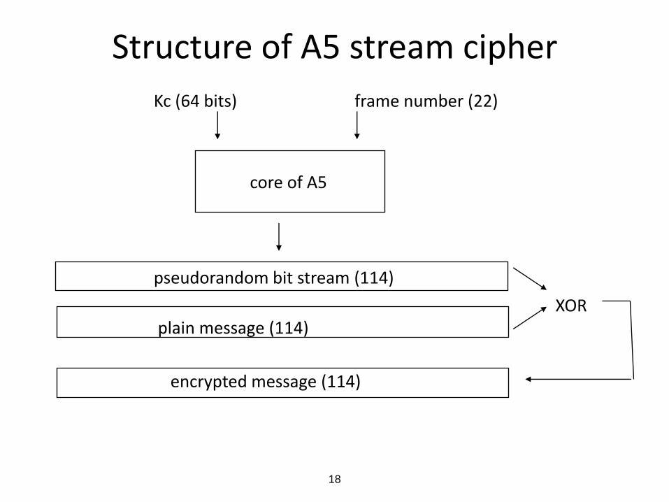
• The encryption algorithm is called A5. The first two versions A5/1 and A5/2 were standardized but the specs are confidential and managed by GSM Association. The third version A5/3 is publicly available. All make use of 64-bit keys Kc.
• As a Rel-9 addition, there is also a 128-bit key algorithm A5/4. – Deployment of this is more difficult than in A5/3 case because longer
keys require changes in many parts of the system
18
Structure of A5 stream cipher
Kc (64 bits) frame number (22)
core of A5
pseudorandom bit stream (114)
XOR plain message (114)
encrypted message (114)

19
GSM security protocol
MS (SIM) MSC/VLR HLR IMSI, Ki (and BTS) {{IMSI,Ki}} IMSI / TMSI IMSI RAND RAND, XRES, Kc Kc SRES SRES=XRES ? encrypted TMSI

20
Barkan–Biham A5/2 Attack (from 2003)
Exploited weaknesses in cryptographic algorithms: – A5/2 can be broken very fast
… and exploited also other legacy features in the GSM security system: – A5/2 was a mandatory feature in terminals – Call integrity based only on encryption – Same Kc is used in different algorithms – Attacker can force the victim MS to use the same Kc by RAND replay
An example attack: Decryption of strongly encrypted call
– Catch a RAND and record a call encrypted with Kc and A5/3 – Replay the RAND and tell the MS to use A5/2 – Analyse Kc from the received encrypted uplink signal – Decrypt the recorded call with Kc
21
Countermeasure
• Withdrawal of A5/2 from all 3GPP terminals (starting from release 6)

22
GPRS security
• Similar to GSM security
• SGSN takes the role of MSC/VLR for authentication
• Encryption terminates also in SGSN – Embedded in Logical Link Layer (LLC)
– Counter: frame number (22 bits) replaced by LLC counter (32 bits)
– Algorithms:
• GEA1 (confidential, weakest)
• GEA2 (confidential)
• GEA3 (publicly available)
• GEA4 (Rel-9 addition; first to use 128-bit keys instead of 64-bit keys)
23
3G security

24
3G security background • Leading design principles were:
– Move useful 2G security features to 3G
– Add countermeasures against real weaknesses in 2G
• Main weaknesses in GSM: • Active attacks are possible (false BS etc.) • Authentication data (e.g. cipher keys) sent in clear inside one
network and between networks • Cipher keys too short (if 64 bits) • Secret algorithms do not create trust
• Main security characteristics in GSM ( = 2G ) : • User authentication & radio interface encryption
• SIM used as security module
• Operates without user assistance
• Requires minimal trust in serving network

25
Active attack • A false element masquerades
– as a base station towards terminal
– as a terminal towards network
• Objectives of the attacker: – eavesdropping
– stealing of connection
– manipulating data
MS false BS BS

26
3G system architecture
based on GSM/GPRS architecture
UTRAN
GGSN
PSTN/ISDN
IP networks
SCP HLR
GMSC
3G-SGSN Iu
MS
BS
BS
BS
BS
RNC
RNC
MSC/VLR
Iur
Iub
(optional)
Encryption & integrity
Execution of authentication
Transport
of auth data

27
Mutual authentication • There are three entities involved:
– Home network HN (AuC)
– Serving network SN (VLR/SGSN)
– Mobile station MS (USIM)
• Executed whenever SN decides
• The idea: SN checks MS’s identity (as in GSM) and MS checks that SN has authorization from HN
• A master key K is shared between MS and HN • GSM-like challenge-response in user-to-network authentication • Network proves its authorization by giving a token AUTN which is
protected by K and contains a sequence number SQN
• Each operator may use its own algorithms for authentication • At the same time keys for ciphering and integrity checking are
derived • Ciphering and integrity checking are performed in MS and in RNC
and these are independent of the authentication mechanism

28
Generation of security parameters SN HN
IMSI
RAND K SQN
XRES AUTN CK IK
RAND, AUTN, XRES, CK, IK

29
3G Authentication & key agreement
MS SN
RAND, AUTN
RAND K AUTN
RES SQN CK IK
RES
checks whether SQN is big enough? checks RES = XRES?

30
3G ciphering mechanism • Between UE and RNC • Stream cipher like in GSM and GPRS • Key length 128 bits • Key lifetime could be limited.
• Begins with RNC sending “Security mode command”
• Layer: • RLC for non-transparent RLC mode • MAC for transparent RLC mode
• Both MSC/VLR and SGSN may give cipher keys to RNC. One key is used for each CN domain user data. The key for signaling data is changed whenever a new key is generated (which means key changes during active connections).

31
3G Ciphering algorithm
COUNT-C/32 DIRECTION/1
BEARER/8 LENGTH
CK/128
KEYSTREAM BLOCK
Plaintext MAC SDU or Ciphered MAC
SDU or
RLC PDU (data part) RLC PDU (data part)

32
KASUMICK
COUNT || BEARER || DIRECTION || 0...0
CKCKCK
KS[0] ... KS[63] KS[64] ... KS[127] KS[128] ... KS[191]
BLKCTR = 0
BLKCTR = 1 BLKCTR = 2BLKCTR = n
CT[ i ] = PT[ i ] XOR KS[ i ]
KASUMICK’
KASUMIKASUMIKASUMI
UEA1 (based on KASUMI block cipher)

33
KASUMI block cipher
C
Fig. 1: KASUMI
P
FO1FL1
FO3FL3
FO5FL5
FO7FL7
FO2 FL2
FO4 FL4
FO6 FL6
FO8 FL8
KL1 KO1, KI1
FIi1 KIi1
KOi1
FIi2 KIi2
KOi2
FIi3 KIi3
KOi3
S9
S7
S9
zero-extend
zero-extend
truncate
KIij1 KIij2
32 32
64
16 16
32 16
9 7
Fig.2: FO Function Fig.3: FI Function
Fig.4: FL Function
bitwise AND operation
bitwise OR operation
one bit left rotation
32
16 16
KLi1
KLi2
KL6
KL8
KL7
KL2
KL5
KL4
KL3
KO2, KI2
KO3, KI3
KO4, KI4
KO5, KI5
KO6, KI6
KO7, KI7
KO8, KI8
S7
truncate
34
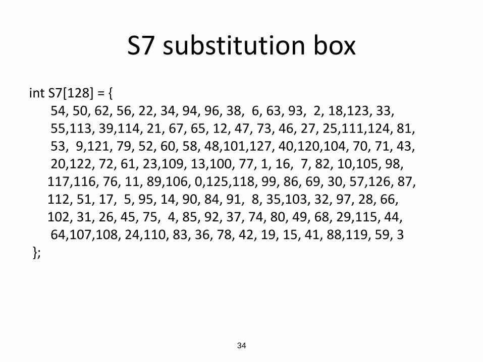
S7 substitution box
int S7[128] = { 54, 50, 62, 56, 22, 34, 94, 96, 38, 6, 63, 93, 2, 18,123, 33, 55,113, 39,114, 21, 67, 65, 12, 47, 73, 46, 27, 25,111,124, 81, 53, 9,121, 79, 52, 60, 58, 48,101,127, 40,120,104, 70, 71, 43, 20,122, 72, 61, 23,109, 13,100, 77, 1, 16, 7, 82, 10,105, 98, 117,116, 76, 11, 89,106, 0,125,118, 99, 86, 69, 30, 57,126, 87, 112, 51, 17, 5, 95, 14, 90, 84, 91, 8, 35,103, 32, 97, 28, 66, 102, 31, 26, 45, 75, 4, 85, 92, 37, 74, 80, 49, 68, 29,115, 44, 64,107,108, 24,110, 83, 36, 78, 42, 19, 15, 41, 88,119, 59, 3 };

35
Integrity protection • Purpose: to authenticate individual RRC signaling
messages • Examples of critical messages:
– from MS to RNC:
- MS capabilities, including authentication, ciphering and integrity algorithm capabilities
- Security control accept/reject message - Called party number in a mobile originated call - Periodic message authentication messages - Cell and URA updates
– from RNC to MS:
- Security mode command, including whether ciphering is enabled or not and the ciphering and integrity algorithms that are used
- Periodic message authentication messages.
• Almost all RRC messages are integrity protected

36
Integrity mechanism DIRECTION/1 IK/128 COUNT-I/32 FRESH/32
one-way function
RRC message MAC (32)
For UIA1: the one-way function is based on KASUMI
block cipher

37
Second set of algorithms based on SNOW3G
• These are called UEA2 and UIA2
• Added in 3GPP release 7 (in 2006)
• SNOW3G is a stream cipher – based on SNOW 2.0 (Nordic origin)
– structure of UEA2 is straight-forward

38
SNOW 3G : structure
LFSR
R1
FSM
+
R1R1
++
+
+
S1 S2
Key stream

39
UIA2 based on SNOW 3G COUNTIK
SNOW 3G
fM
BEARER
DIRECTION
Padded
message M
Trunc
OTP
PQ
MAC

40
Network domain security (based on IPsec)
Za
Zb
Zb
Zb
SEG A
Security domain A
Security domain B
SEG B
NE A - 1
NE A - 2
Zb
Zb
Zb
NE B - 1
NE B - 2
IKE "connection"
ESP Security Association
41
Status on 3G security today
• 3G security resilient against security analyses
• No significant attacks known on cryptographic algorithms
• No false base station attacks seem possible
• 3G security seems still sufficient for 3G networks

42
Brief introduction to LTE (and SAE)
43
SAE / LTE: What and why? SAE = System Architecture Evolution LTE = Long Term Evolution (of radio networks) • LTE offers higher data rates, up to 100 Mb/sec
– Multi-antenna technologies – New transmission schema based on OFDM – Signaling/scheduling optimizations
• SAE offers optimized (flat) IP-based architecture – Two network nodes for user plane – Simplified protocol stack – Optimized inter-working with legacy cellular, incl. CDMA – Inter-working with non-3GPP accesses, incl. WiMAX

44
SAE / LTE: What and why? SAE = System Architecture Evolution
LTE = Long Term Evolution (of radio networks)
• Technical terms:
– E-UTRAN = Evolved UTRAN (LTE radio network)
– EPC = Evolved Packet Core (SAE core network)
– EPS = Evolved Packet System ( = RAN + EPC )

45
SAE / LTE : designed by whom?
3GPP TSG SA : stage 2 specifications for LTE/SAE
3GPP TSG RAN: stage 3 specs for LTE
3GPP TSG CT: stage 3 specs for SAE
LTE/SAE is included in 3GPP Release 8 specifications
Security design by 3GPP TSG SA Working Group 3 (SA3)
46
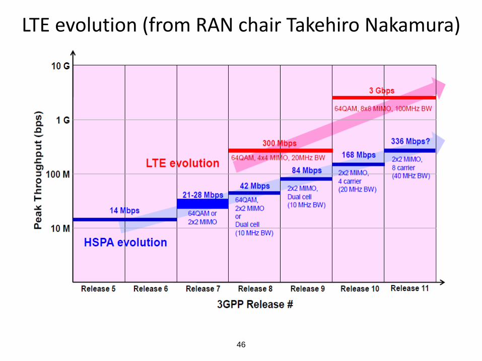
LTE evolution (from RAN chair Takehiro Nakamura)

47
EPS architecture (non-roaming case)
SGi
S12
S3
S1-MME
PCRF
Gx
S6a
HSS
Operator's IP Services
(e.g. IMS, PSS etc.)
Rx
S10
UE
SGSN
LTE-Uu
E-UTRAN
MME
S11
S5 Serving Gateway
PDN Gateway
S1-U
S4
UTRAN
GERAN
From 3GPP TS 23.401

48
EPS architecture (one of the roaming variants)
S6a
HSS
S 5
S3
S1 - MME
S10
GERAN
UTRAN
S G SN
MME
S11
Serving G ateway UE
" LTE - Uu"
E - UTRAN
S4
HPLMN
VPLMN
V - PCRF
Gx
SGi
PDN G ateway
S1 - U
H - PCRF
S9
Home Operator’s IP
Services
Rx
Visited Oper ator PDN
S12
From TS 23.401

49
E-UTRAN architecture
eNB
MME / S-GW MME / S-GW
eNB
eNB
S1
S1
S1
S1
X2X2
X2
E-UTRAN
From 3GPP TS 36.300

50
Essential elements of EPS
From “LTE security”

51
EPS archi with non-3GPP access (non-roaming)
SGi
PCRF
Gx
HSS
SWn
Operator's IP Services (e.g. IMS, PSS, etc.)
SWm
SWx
Untrusted Non - 3GPP IP
Access SWa
HPLMN
Non-3GPP Networks
S6b
Rx
PDN Gateway
Trusted Non-3GPP IP Access
STa
S2c S2c
ePDG 3GPP AAA
Server
UE
Gxa
Gxb
Gxc
S5
S6a
S2c
3GPP Access
Serving Gateway
From TS 23.402

52
Roaming case (one variant)
hPCRF
HSS
Trusted Non-3GPP IP
Access
HPLMN
SWd
Non-3GPP Networks
S6b
VPLMN
vPCRF
PDN Gateway
3GPP AAA Proxy
3GPP AAA Server
Gxa
S9
S2a
Gx
Rx
SGi
SWx
STa
Visited network IP services or proxies to home network services or PDN
Rx
Gxb
ePDG S2b
SWn
SWm
Untrusted Non-3GPP IP
Access SWa
S5
Gxc
S6a Operator's IP
Services (e.g. IMS, PSS
etc.)
3GPP Access
Serving Gateway
From TS 23.402

53
LTE Security

54
Implications of LTE/SAE architecture on security
• Flat architecture: – All radio access protocols terminate in one node: eNodeB – IP protocols also visible in eNB
• Security implications due to – Architectural design decisions – Interworking with legacy and non-3GPP networks – Allowing eNB placement in untrusted locations – New business environments with less trusted networks
involved – Trying to keep security breaches as local as possible
• As a result (when compared to UTRAN/GERAN): – Extended Authentication and Key Agreement – More complex key hierarchy – More complex interworking security – Additional security for eNB (compared to NodeB/BTS/RNC)

55
Threats against EPS (1/2)
• Threats against user identity • Other threats against privacy • Threats of UE tracking:
– e.g. tracking a user based on an IP address that could potentially be linked to an IMSI
• Threats related to handovers: – e.g. forcing a handover to a compromised base station by a powerful signal;
• Threats related to base stations and last-mile transport links: – e.g. injecting packets directly into the last-mile transport link or physical
compromise of base stations in vulnerable locations;
• Threats related to multicast or broadcast signalling: – e.g. broadcasting false system information
• Threats related to denial of service: – e.g. by means of radio jamming or launching a distributed attack from many
UEs

56
Threats against EPS (2/2)
• Threats of misusing network services: – e.g. flooding the network from inside the network by
compromised elements or from outside
• Threats against the radio protocols: – e.g. faking or modifying the first radio connection
establishment messages from UE
• Threats related to mobility management: – e.g. disclosure of sensitive data about users’ locations;
• Threats of manipulation of control plane data • Threats of unauthorised access to the network
57
EPS security requirements (high-level)
• EPS shall provide a high level of security. • Any security lapse in one access technology shall not
compromise other accesses. • EPS should provide protection against threats and
attacks. • EPS shall support authenticity of information between
the terminal and the network. • Appropriate traffic protection measures should be
provided. • EPS shall ensure that unauthorised users cannot
establish communications through the system.

58
EPS security requirements (service-related)
• EPS shall allow a network to hide its internal structure from the terminal.
• Security policies shall be under home operator control. • Security solutions should not interfere with service delivery
or handovers in a way noticeable for end-users. • EPS shall provide support for lawful interception. • Rel-99 (or newer) USIM is required for authentication of the
user towards EPS. • USIM shall not be required for re-authentication in
handovers (or other changes) between EPS and other 3GPP systems, unless requested by the operator.
• EPS shall support IMS emergency calls.

59
EPS security requirements (privacy-related)
• EPS shall provide several appropriate levels of user privacy for communication, location, and identity.
• Communication contents, origin, and destination shall be protected against disclosure to unauthorised parties.
• EPS shall be able to hide user identities from unauthorised parties.
• EPS shall be able to hide user location from unauthorised parties, including another party with which user is communicating.

60
EPS security features • Confidentiality of the user and device identities
• Authentication between the UE and the network
• Confidentiality of user and signalling data
• Integrity of signalling data
• Visibility and configurability of security
• Platform Security of the eNodeB
• Lawful interception
• Emergency calls
• Interworking security
• Network domain security
• IMS security for voice over LTE

61
Major design decisions for EPS security (1/2)
• Permanent security association – Inherited from GSM and 3G
• Interfaces in UE and HSS/HLR – ME-USIM interface is fully standardized but HSS-AuC is not
• Reuse of 3G USIMs
• No reuse of 2G SIMs in EPS
• Delegated authentication – Inherited from GSM and 3G
• Reuse of 3G AKA
• Cryptographic network separation
• Serving network authentication

62
Major design decisions for EPS security (2/2)
• Termination point for encryption and integrity protection
– Flat architecture required moving to base station site
• New key hierarchy in EPS
• Key separation in handovers
• Homogeneous security for heterogeneous access networks
• User identity confidentiality not protected against active attackers
• Other „NOT“ – decisions: – No integrity protection for user plane on radio interface
– No (cryptographic) non-repudiation of charging

63
Identity confidentiality in EPS (1/2) • Mechanism inherited from GSM and 3G
• User’s permanent identity (IMSI) is sent to the network only if network cannot identify the UE otherwise
ME/USIM MME
Identity Request
Identity Response (IMSI)
From 33.401

64
Identity confidentiality in EPS (2/2)
• Network assigns a temporary identity for the UE
• It is sent to the UE in encrypted message
• In GSM/3G the temporary identity is – TMSI for CS domain
– P-TMSI for PS domain
• In EPS the temporary identity is called GUTI (Globally Unique Temporary Identity)

65
Authentication and key agreement

66
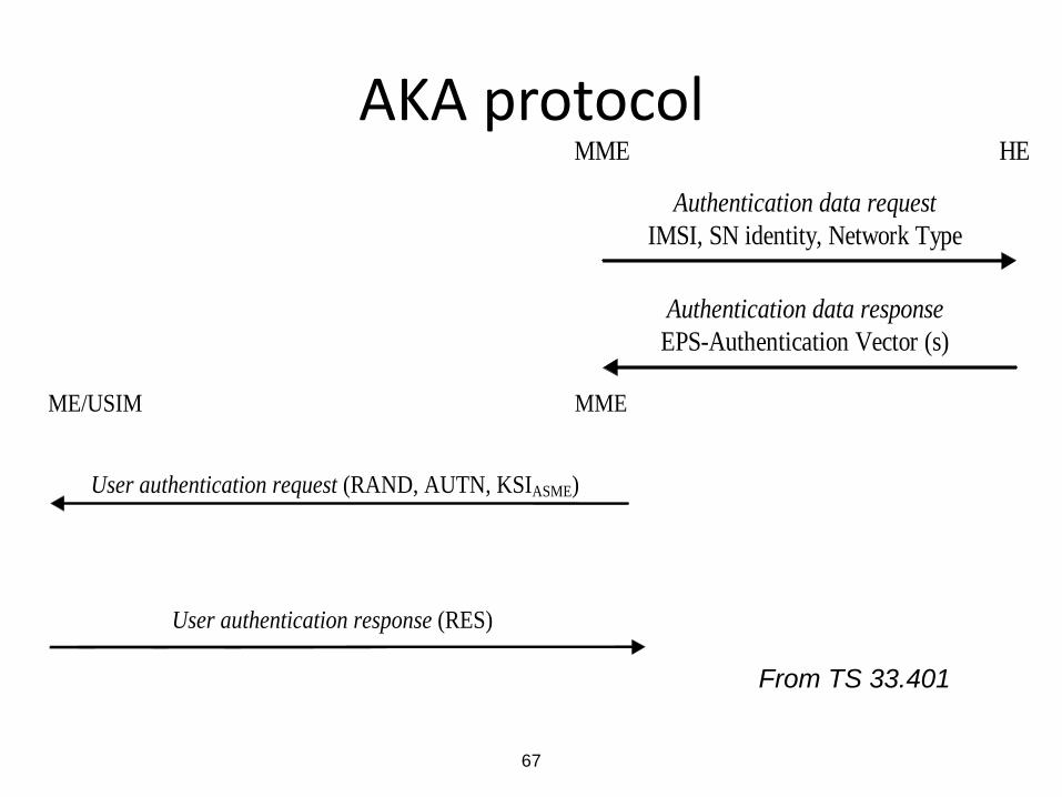
Authentication and key agreement
• HSS generates authentication data and provides it to MME
• Challenge-response authentication and key agreement procedure between MME and UE
S12
S3
S1-MME S6a
HSS
S10
UE
SGSN
LTE-Uu
E-UTRAN
MME
S11
S5 Serving Gateway
S1-U
S4
UTRAN
GERAN
67
AKA protocol
MME HE
Authentication data request
IMSI, SN identity, Network Type
Type
Authentication data response
EPS-Authentication Vector (s)
ME/USIM MME
User authentication request (RAND, AUTN, KSIASME)
User authentication response (RES)
From TS 33.401

68
USIM ME
Auth Info Req
(IMSI, SN id)
MME
Auth Info Answer
(RAND, XRES,
KASME, AUTN)
Authentication Resp
(RES)
Authentication Req
(RAND || AUTN)
HSS
Distribution of
EPS
authentication
vectors from
HSS to MME
Generate EPS AV
incl. SN id
Compute KASME
incl. SN id
Compare
RES and XRES
Authentication
and key
establishment
Verify AUTN
Compute RES
Compute
CK and IK
From “LTE security”

69
Generation of UMTS and EPS AV’s
SQN
RANDAMF
MAC
KDF
f2f1
EPS AV := RAND || XRES || KASME || AUTN
UMTS AV := RAND || XRES || CK || IK || AUTN
AUTN := SQN xor AK || AMF || MAC
KASME
SN idSQN xor AK
Generate RAND
Generate SQN
f3 f4 f5
XRES CK IK AK
K
From “LTE security”

70
Verification in USIM
SQN
RAND
AMF
XMAC
f2f1
Verify that SQN is in the correct range
Verify MAC = XMAC
f5
f3 f4
RES CK IK
K
MACSQN xor AK
AK xor
AUTN
From “LTE security”

71
Authentication failure types
• MAC code failure – XMAC differs from MAC
• Synchronization failure – SQN not in correct range
– Re-synchronization is possible (next slide)
• Incorrect type of AV – Check a specific AMF separation bit (see later slide)
• Invalid authentication response – XRES differs from RES

72
Authentication re-synchronization parameter
RAND
AMF
MAC-S
f5*f1*
AUTS = SQNMS xor AK || MAC-S
xor
AK SQNMS xor AK
K
SQNMS
From “LTE security”

73
LTE Data protection

74
Confidentiality and integrity of signalling
• RRC signalling between UE and E-UTRAN
• NAS signalling between UE and MME
• S1 interface signalling
– protection is not UE-specific
– optional to use
S12
S3
S1-MME S6a
HSS
S10
UE
SGSN
LTE-Uu
E-UTRAN
MME
S11
S5 Serving Gateway
S1-U
S4
UTRAN
GERAN

75
EPS signalling protection
UE eNB MME
IPsec
Integrity & encryption
Int. & encr.
NAS NAS
RRC S1-APRRC
PDCPPDCP
S1-AP
IP IP
From “LTE security”

76
User plane confidentiality
• S1-U protection is not UE-specific
– (Enhanced) network domain security mechanisms (based on IPsec)
– Optional to use
• Integrity is not protected for various reasons, e.g.:
– performance
– limited protection for application layer
S12
S3
S1-MME S6a
HSS
S10
UE
SGSN
LTE-Uu
E-UTRAN
MME
S11
S5 Serving Gateway
S1-U
S4
UTRAN
GERAN

77
EPS user plane protection
UE eNB S-GW
IPsec
Encr.
app
GTP-UPDCPPDCP GTP-U
IP IP
From “LTE security”

78
Ciphering mechanism
PLAINTEXT
BLOCK
EEA
COUNT DIRECTION
BEARER LENGTH
KEY
KEYSTREAM
BLOCK
CIPHERTEXT
BLOCK
EEA
COUNT DIRECTION
BEARER LENGTH
KEY
KEYSTREAM
BLOCK
PLAINTEXT
BLOCK
Sender
Receiver
Extract from 3GPP TS 33.401
79
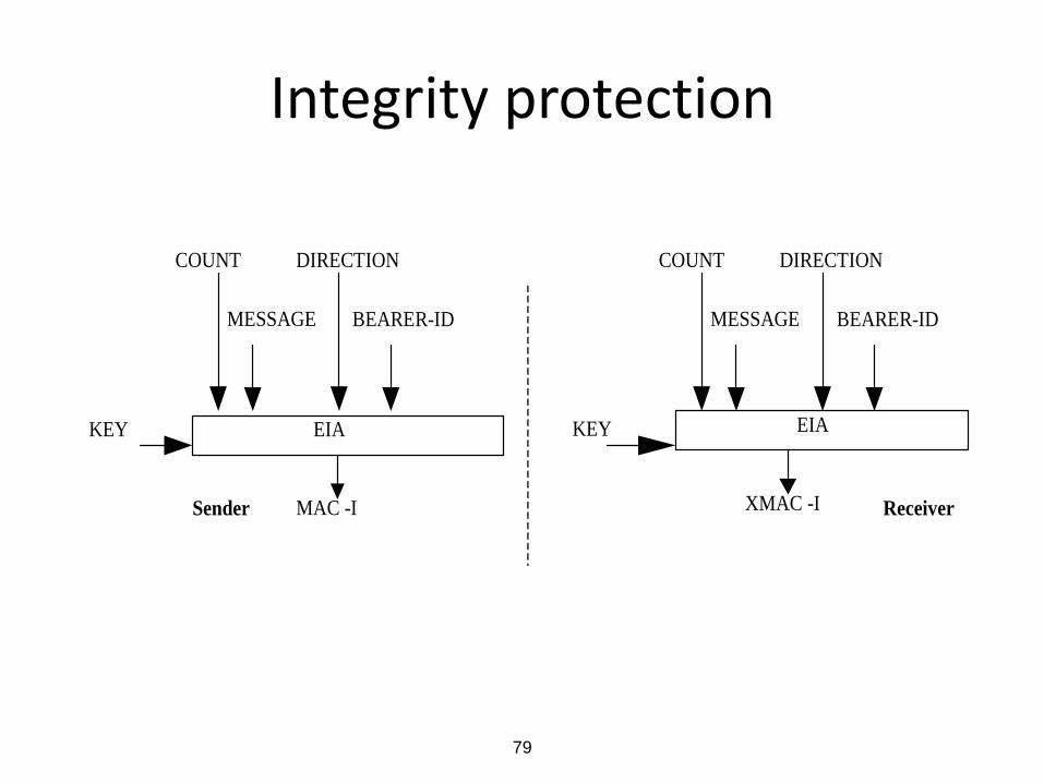
Integrity protection
EIA KEY
MAC -I Sender
COUNT DIRECTION
MESSAGE BEARER-ID
EIA
XMAC -I
COUNT DIRECTION
MESSAGE BEARER-ID
KEY
Receiver
80
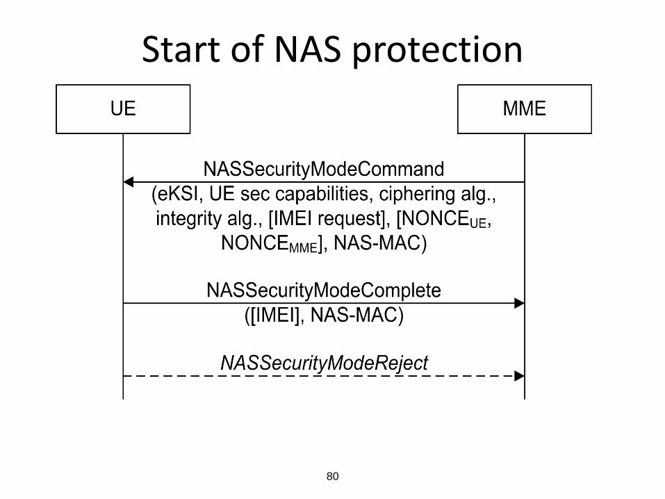
Start of NAS protection

81
Start of AS protection

82
LTE Key hierarchy
USIM / AuC
UE / MME
KASME
K
KUPenc
KeNB / NH
KNASint
UE / HSS
UE / eNB
KNASenc
CK, IK
KRRCint KRRCenc
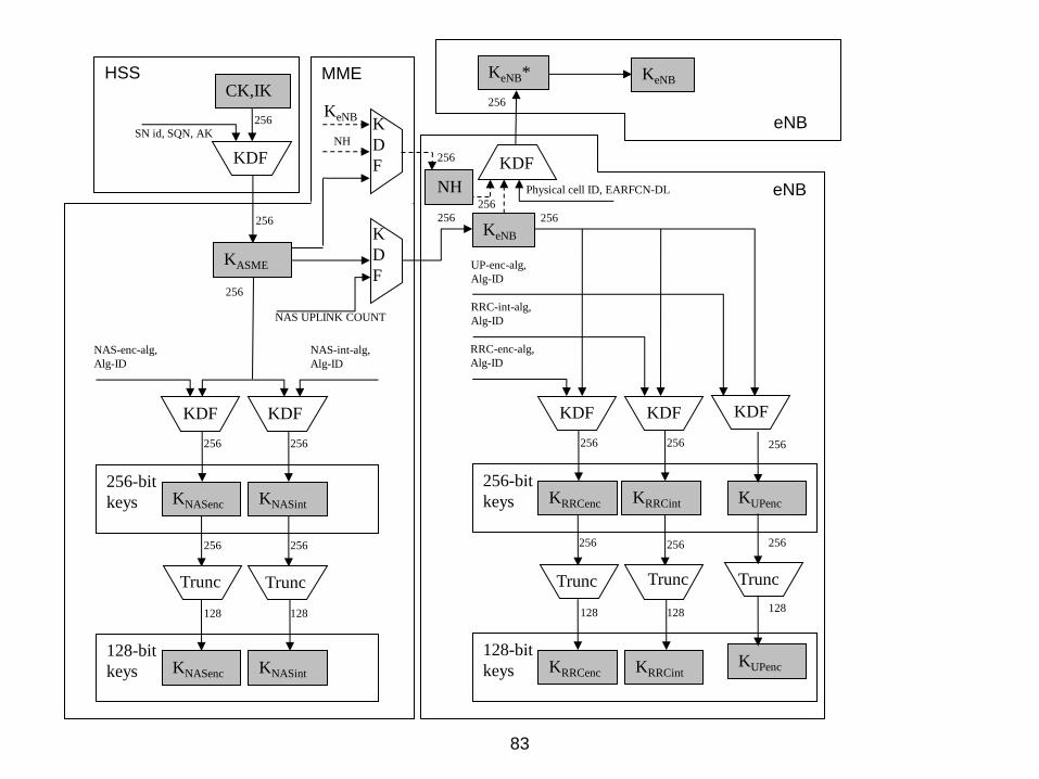
83
MME HSS CK,IK
KDF
256
256
SN id, SQN, AK
KeNB
KASME
256
KDF
K
D
F
KDF KDF
256-bit
keys KNASenc KNASint
128-bit
keys KNASenc KNASint
Trunc Trunc
256 256
128 128
256
256 256
NAS-enc-alg,
Alg-ID
NAS-int-alg,
Alg-ID
NAS UPLINK COUNT
KDF KDF
256-bit
keys KRRCenc KRRCint
128-bit
keys KRRCenc KRRCint
Trunc Trunc
256 256
128 128
256 256
RRC-enc-alg,
Alg-ID
RRC-int-alg,
Alg-ID
UP-enc-alg,
Alg-ID
256
256
Physical cell ID, EARFCN-DL
256
KeNB
eNB
eNB
KeNB*
KDF
KUPenc
KUPenc
256
256
128
Trunc
K
D
F
NH
NH
KeNB
256

84
Cryptographic network separation (1/2)
Network id
USIM / AuC
UE / MME
KASME
K
KUPenc
KeNB / NH
KNASint
UE / HSS
UE / eNB
KNASenc
CK, IK
KRRCint KRRCenc

85
Cryptographic network separation (2/2)
• Authentication vectors in EPS are specific to the serving network AV’s usable in EPS cannot be used in GERAN or UTRAN
• AV’s usable for UTRAN/GERAN access cannot be used for E-UTRAN access – Solution by a “separation bit” in AMF field
• On the other hand, Rel-99 USIM is sufficient for EPS access ME has to check the “separation bit” (when accessing E-
UTRAN)
• As one consequence, “EAP-AKA’ “ was created in IETF

86
LTE crypto-algorithms

87
Crypto-algorithms
• Two sets of algorithms from Day One – If one breaks, we still have one standing – Should be as different from each other as possible – AES and SNOW 3G chosen as basis ETSI SAGE has
specified/chosen modes
• A third algorithm set added for Release 11 – The base algorithm ZUC is of Chinese origin and usable in China
• Rel-99 USIM is sufficient master key 128 bits – All keys used for crypto-algorithms are 128 bits but included
possibility to add 256-bit keys later (if needed)
• Deeper key hierarchy (one-way) key derivation function needed – HMAC-SHA-256 chosen as basis

88
Structure of ZUC

89
Structure of EEA3

90
Structure of EIA3

91
ZUC resistance verified against:
• Weak key attacks • Guess-and-Determine Attacks • BDD Attacks • Inversion Attacks • Linear Distinguishing Attacks • Algebraic Attacks • Chosen IV Attacks • Time-Memory-Data Trade-Off Attacks • Timing Attacks

92
Conclusions of ETSI SAGE evaluations of EEA3/EIA3
• “One stated objective for the design was that the new algorithms be substantially different from the first and second LTE algorithm sets, in such a way that an attack on any one algorithm set would be unlikely to lead to an attack on either of the others. In SAGE’s view this objective is not fully met – there are some architectural similarities between ZUC and SNOW 3G, and it is possible that a major advance in cryptanalysis might affect them both. However: – there are important differences too, so ZUC and SNOW 3G by no
means “stand or fall together”; – and in any case the raison d’être of this new algorithm set is very
different from that of the first two, so the objective is considerably less important than making the first and second algorithm sets different from each other.
• SAGE therefore does not consider this a barrier to acceptance of the new algorithms. Indeed, both of the paid evaluation teams noted that the ZUC design inherits some strong security properties from SNOW 3G, while adding further protection against as yet unknown attacks.”

93
Need for algorithm agility: example
time
Theory
break of
algo 2
Spec
work for
algo 3
Practical
break of
algo 2
Algo 3
implemented Majority of
terminal base
supports algo 3

94
Need for algorithm agility: example
time
Theory
break of
algo 2
Spec
work for
algo 3
Practical
break of
algo 2
Algo 3
implemented Majority of
terminal base
supports algo 3
Dependent on
one algo only

95
Caveat: Security of algorithm capability negotiation
• Algorithm capabilities exchanged first without protection
• Re-exchanged and verified once integrity protection is turned on
all integrity algorithms should resist real-time attacks in the beginning of the connection
• If this is not the case anymore, broken algorithm has to be withdrawn completely from the system – In the same way as A5/2 is withdrawn from GSM

96
Handovers and interworking
97
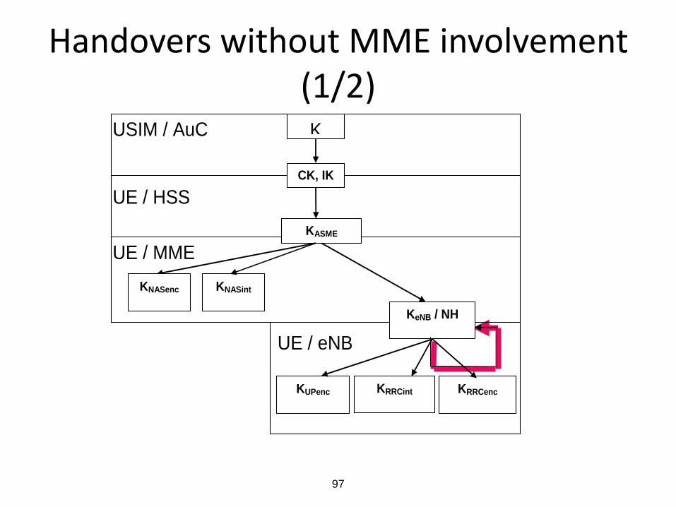
Handovers without MME involvement (1/2)
USIM / AuC
UE / MME
KASME
K
KUPenc
KeNB / NH
KNASint
UE / HSS
UE / eNB
KNASenc
CK, IK
KRRCint KRRCenc

98
Handovers without MME involvement (2/2)
• Handovers are possible directly between eNB’s for performance reasons
• If keys would be passed as such, all eNB’s in a “HO chain” would know all the keys one compromised eNB would compromise all eNB’s in the “HO chain”
• Countermeasures: – One-way function used before key is passed (Backward
security) – MME is involved after the HO for further key passes
(Forward security, effective after two hops) – When MME involved already during the HO, Forward
security is effective already after one hop

99
KeNB derivations
KASME
NH
NHKeNB*
(KeNB)
Initial
NAS uplink COUNT
NCC = 1
NCC = 2
NCC = 0KeNB KeNB KeNB
PCI,
EARFCN-DL
KeNB* KeNB*
KeNB KeNB KeNB
KeNB* KeNB*
PCI,
EARFCN-DL
PCI,
EARFCN-DL
PCI,
EARFCN-DL
PCI,
EARFCN-DL
NHKeNB*
NCC = 3KeNB KeNB KeNB
KeNB* KeNB*
PCI,
EARFCN-DL
PCI,
EARFCN-DL
PCI,
EARFCN-DL
From TS 33.401

100
Interworking with UTRAN/GERAN (1/2)
• UE may be registered in both SGSN and MME simultaneously
when moving from one system (source) to the other (target) both
native keys (created earlier in the target system) and mapped keys (converted from the keys in the source
system) may exist
– Note: native keys exist only for Rel-8 SGSN, not for legacy SGSN

101
Interworking with UTRAN/GERAN (2/2)
• Idle mode transition – From E-UTRAN to UTRAN: either mapped or native
keys are used (depending on the identity used in Routing Area Update Request)
– From UTRAN to E-UTRAN: native keys are used but an exceptional case exists also
• Handover – From E-UTRAN to UTRAN: mapped keys are used – From UTRAN to E-UTRAN: mapped keys are used but it
is possible to activate the native keys after HO completed (using key-change-on-the-fly procedure)
102
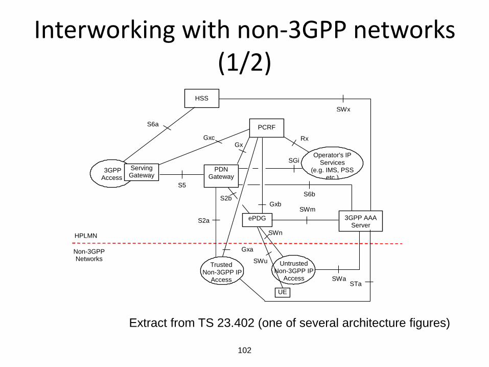
Interworking with non-3GPP networks (1/2)
SGi
PCRF
Gx
HSS
S2b
SWn
Operator's IP Services
(e.g. IMS, PSS etc.)
SWm
SWx
Untrusted Non-3GPP IP
Access SWa
HPLMN
Non-3GPP Networks
S6b
Rx
PDN Gateway
ePDG 3GPP AAA Server
Gxb
S2a
Gxa
Trusted Non-3GPP IP
Access STa
Gxc
S5
S6a
3GPP Access
Serving Gateway
UE
SWu
Extract from TS 23.402 (one of several architecture figures)

103
Interworking with non-3GPP networks (2/2)
• Three options for mobility between 3GPP and non-3GPP networks: – Proxy Mobile IP: no user-specific security associations between
the Proxy and Home Agent – Client MIPv4: tailor-made security mechanisms are used – Dual Stack MIPv6: IPsec with IKEv2 is used between UE and HA
• IPsec tunnel (with evolved Packet Data Gateway) is used in case the non-3GPP network is untrusted by the operator (of EPS network)
• Authentication is run by EAP-AKA or EAP-AKA’ procedures, in both cases based on USIM

104
EAP-AKA’ authentication for trusted non-3GPP
access
Non-3GPP
Access NetworkUE
3. EAP-Response/Identity
2. EAP-Request/Identity
3GPP
AAA
Server
16. EAP-Response/AKA’-
Challenge
14. EAP-Request/AKA’-Challenge
HSS
1. Connection establishment
4.+5. AAA
[EAP-Response/Identity]
6. AAA
[EAP-Request/AKA’-Identity] 7. EAP-Request/AKA’-Identity
8. EAP-Response/AKA’-Identity 9. AAA
[EAP-Response/AKA’-Identity]
10.
11.
13. AAA
[EAP-Request/AKA’-Challenge]
17. AAA
[EAP-Response/AKA’-Challenge]
15.
18.19. AAA
[EAP-Request/AKA’-Notif.]20. EAP-Request/AKA’-Notif.
21. EAP-Response/AKA’-Notif. 22. AAA
[EAP-Response/AKA’-Notif.]
23. AAA
[EAP-Success]
24. EAP-Success
12.
25.

105
IKEv2 and EAP AKA for untrusted non-3GPP access
ePDG
2. IKE_AUTH Request
[Identity] 3. AAA
[Identity]
4. 5. AAA
[EAP-Request/AKA-Challenge] 6. IKE_AUTH Response
[EAP-Request/AKA-Challenge,
Cert, AUTH]
7. IKE_AUTH Request
[EAP-Response/AKA-Challenge] 8. AAA
[EAP-Response/AKA-Challenge]
8a.
9. AAA
[EAP-Success + MSK]
10. 11. IKE_AUTH Response
[EAP-Success]
12. IKE_AUTH Request
[AUTH]
15. IKE_AUTH Response
[AUTH]
1. IKE_SA_INIT
16.
UE HSS
3GPP
AAA
Server
8b. AAA
[EAP-Request/AKA-Notif.] 8c. IKE_AUTH Response
[EAP-Request/AKA-Notif.]
8d. IKE_AUTH Request
[EAP-Response/AKA-Notif.] 8e. AAA
[EAP-Response/AKA-Notif.]
13.+14.

106
Lawful interception

107
Lawful interception in 3GPP
LEA
3 GMS nodeAdministration
Function
IRI
CC
Delivery
Function
3GMS
IRI
CC
LEA
NETWORK RELATED
DATA
TECHNICAL INTERCEPTION
HANDOVER INTERFACE
INTERCEPT
REQUEST
INTERCEPT
REQUEST
MOBILE TARGET

108
LI specifications
• Requirements in TS 33.106 (11 pages)
• Architecture, functions, information flows in TS 33.107 (129 p.)
• Description of the Handover Interfaces, incl. ASN1, in TS 33.108 (189 p.)

109
When LI is invoked: examples
• A circuit switched call is requested originated from, terminated to, or redirected by the target
• Location information related to the target facility is modified by the subscriber attaching or detaching from the network, or if there is a change in location
• An SMS transfer is requested - either originated from or terminated to the target
• A data packet is transmitted to or from a target

110
What is intercepted ? • CC = Content of Communications
– Intercepted from media plane entities, e.g. in EPS: Serving Gateway
• IRI = Intercept Related Information – E.g. in the case of Attach:
• Observed MSISDN • Observed IMSI • Observed ME Id • Event Type • Event Time • Event Date • Network Element Identifier • Location Information • Failed attach reason • Etc.
111
Base station security

112
NDS enhancements for EPS
Home Network
Serving Network
HSSMME
S-GW
IPsec
UICC
ME
Authentication data
transfer
Mutual authentication and
key agreement
IPsecIP
sec
NAS protection
AS protection
UP encryption
From “LTE security”

113
Configuration of eNB
– Communication between the remote/local O&M systems and the eNB mutually authenticated.
– The eNB shall be able to ensure that software/data change attempts are authorized
– Confidentiality and integrity of software transfer towards the eNB ensured.
– etc.

114
Secure environment inside eNB
– Secure storage of sensitive data, e.g. long term cryptographic secrets and vital configuration data.
– The secure environment shall support the execution of sensitive functions, e.g. en-/decryption of user data.
– The secure environment shall support the execution of sensitive parts of the boot process.
– Only authorised access shall be granted to the secure environment.
– etc.

115
Certificate enrolment for base stations RA/CA SEG
Base Station
Operator root certificate
is pre-installed
Vendor root certificate
is pre-installed
Enrolled base station
certificate is used in
IKEv2/IPsec
Vendor-signed certificate of
base station public key is pre-
installed
The base station obtains the
operator-signed certificate on
its own public key from RA/
CA using CMPv2
CMPv2
IPsec
From “LTE security”

116
Example message flow
Base Station RA/CA
14. Confirmation (pkiconf)
11. Certificate confirm (certconf)
8. Initialization Response (ip)
4. Initialization Request (ir)
1. Discover RA/CA address
2. Generate private/public key pair
3. Sign Initialization Request (ir)
5. Authenticate Initialization Request (ir)
6. Generate base station certificate
7. Sign Initialization Response (ip)
9. Authenticate Initialization Response (ip)
10. Sign Certificate confirm (certconf)
12. Authenticate Certificate confirm
(certconf)
13. Sign Confirmation (pkiconf)
15. Authenticate Confirmation (pkiconf)

117
Home base stations: new architecture
Extract from 3GPP TS 33.320
• Concept of Closed Subscriber Group introduced
• Applies also to HSPA base stations
UE H(e)NB SeGW insecure link
Operator’s core
network
H(e)NB-GW
H(e)MS H(e)MS
AAA Server/HSS
L-GW

118
Main area of security for HeNB’s
Operator
Network
Main area of
security measures
HeNB-GW
HeMS
S-GW
HeNBUE SeGW
Insecure
Network
HeMS
AAA
Server
MME
OCSP
Responder
From “LTE Security”

119
Security mechanisms for Home base stations
• Device Integrity Check upon booting, based on Trusted Environment
• secured Clock synchronization • Device authentication
– Mutual authentication between H(e)NB and SeGW – Based on IKEv2 and certificates
• IPsec tunnel between H(e)NB and SeGW • Optionally Hosting Party authentication, based on
UICC • Location verification

120
HeNB authentication
HeNB SeGW
2. IKE_SA_INIT Request
HDR, SAi1, KEi, Ni
9. Access-Request
(Identity(NAI))
AAA-
Server
3. IKE_SA_INIT Response
HDR, SAr1, KEr, Nr, CERTREQ,
N(MULTIPLE_AUTH_SUPPORTED)
4. IKE_AUTH Request
HDR, SK{IDi=FQDN, AUTH,
SAi2, TSi, TSr, CERTREQ, CERT,
N(MULTIPLE_AUTH_SUPPORTED),
N(ANOTHER_AUTH_FOLLOWS)}
11. Access-Challenge
[EAP-Request/AKA-
Challenge] (RAND, AUTN)12. IKE_AUTH Response
HDR SK{EAP-Request/
AKA-Challenge (RAND, AUTN)}
14. IKE_AUTH Request
HDR SK{EAP-Response/
AKA-Challenge (RES)}15. Access-Request
[EAP-Response/AKA-
Challenge] (RES)
17. IKE_AUTH Response
HDR SK{EAP-Success}
19. IKE_AUTH Request
HDR SK{AUTH}
21. IKE_AUTH Response
HDR SK{AUTH, SAr2, TSi, TSr}
6. IKE_AUTH Response
HDR SK{IDr, AUTH, CERT}
8. IKE_AUTH Request
HDR, SK{IDi=NAI)}
HSS
20. Calculate AUTH
parameters using MSK
10. AV retrieval
if needed
5. Verify HeNB’s certificate
7. Verify SeGW’s certificate
13. Verify AKA parameters
1. Device start-up
22. Delete old IKE_SA
16. Access-Accept
(MSK, [TiA,] EAP-Success]
18. Calculate AUTH
parameters using local MSK

121
Management of HeNB’s
SeGWHeNB
(TR-069)
Agent File
Client
HeMS
File Server
(TR-069)
Manager
Type 1 Interface
TR-069
TR-069
File Transfer Protocol
File
Tra
nsfer Pro
tocol
From “LTE Security”

122
Example deployment
TLS
Tunnel
SeGWHeNB
(TR-069)
Agent
File Client
HeMS(TR-069)
Manager
IPsec Tunnel
Type 1 Interface
Bord
er O
pera
tor S
ecurity
Dom
ain
TR-069
TLS
Tunnel
HeMS
File Server
SW
Dow
nlo
ad
File
Tra
nsf
er P
roto
col
Sig
ned
Pack
age
Form
at
123
Base stations and Lawful interception
• Usually lawful interception is not applied in base stations
• However, current work for Local IP Access and Selective IP Traffic Offload may change the situation

124
Security for Voice over LTE
• Two standardized methods: – IMS over LTE
– Circuit Switch Fallback
• Complemented with – Single Radio Voice Call Continuity

125
IMS architecture
P-CSCF /
IMS-ALGIMS UE S-CSCF
HSS
IP-Connectivity
Access Network
IMS
Access GW
From “LTE Security”

126
IMS AKA P-CSCF
1. REGISTER
(Unprotected)
S-CSCF HSS
2. REGISTER
(protected by NDS/IP) 3. Cx-AuthDataReq
(protected by NDS/IP)
4. Cx-AuthDataResp
(protected by NDS/IP)5. 401 Auth_Challenge:
RAND, AUTN, CK, IK
(protected by NDS/IP)
7. 401 Auth_Challenge:
RAND, AUTN
(unprotected)
9. REGISTER:
Digest-Resp(RES; RAND)
(protected by an IPsec SA
created in 6. and 8.)
10. REGISTER
Digest-Resp(RES; RAND)
(protected by NDS/IP)
12. Cx-Put + Cx-Pull
(protected by NDS/IP)
13. Cx-Put Resp + Cx-Pull Resp
(protected by NDS/IP)14. 200 OK
(protected by NDS/IP)15. 200 OK
(protected by an IPsec SA
created in 6. and 8.)
6.
Create IPsec SAs
11.
Auth check
UE
8.
Create IPsec SAs

127
Relay Node architecture
eNB
MME / S-GW MME / S-GW
DeNB
RN
S1
S1S1
S1
X2
X2
E-UTRAN
S1
S11
S1
1Un
(From TS 36.300)

128
Relay Node architecture (cont’d)
• RN appears as regular eNB towards UE
• In some aspects, RN acts like UE towards network
• Goal is to extend coverage and throughput
UE RN DeNB MME/S-GW radio radio backhaul

129
Relay node security
• Security between RN and network based on UICC and AKA
• Secure channel between the UICC and the RN, established based on – Pre-shared keys or
– Certificates
• RN meets platform security requirements similar to those of Home eNB
• User plane integrity is provided between RN and DeNB (unlike between “normal” UE and “normal” eNB) – Key hierarchy extended because of this (see next slide)

130
Relay node security (cont’d)
USIM / AuC
UE / MME
KASME
K
KUPenc
KeNB / NH
KNASint
UE / HSS
UE / eNB
KNASenc
CK, IK
KRRCint KRRCenc KUPint

131
Security aspects typically not standardized
• Product implementations – Secure SW development – HW security – Security testing and audits
• Organizational aspects – Organization of security in a corporation – Security awareness – CERT
• Operational aspects – Anti-virus, vulnerability scanning – Firewalls – Intrusion detection and prevention – Fraud management systems

132
Some future challenges
• Machine-to-machine communications
• Internet of Things / Internet-connected smart objects
• Sensor networks
• Device-to-device communications
• Privacy enhancements
• Impacts of Cloud computing

133
LTE security: Summary

134
Summary
– New architecture and business environment require enhancements to 3G security
– Radio interface user plane security terminates in base station site
– Cryptographic separation of keys
– New security requirements for base stations
– New architecture for Home base stations
– Security mechanisms extended to support Relay Nodes
– New architectures create challenges with Lawful interception

135
More information
www.3gpp.org