Embed Size (px)
Citation preview

Security in Mifare Classic RFIDProject 3, EITF55 Security, 2018 Issued 2018-01-15
Ben SmeetsDept. of Electrical and Information Technology, Lund University, Sweden
Version 2018-01-15
What you will learn
In this project you will• Learn to setup a system to interact with an RFID tag• Study a communication protocol to control light switches• Use Arduino controller• Learn about shortcomings of simple RFID tags• Make security improvements for using RFID tags
1
RFID technology CONTENTS
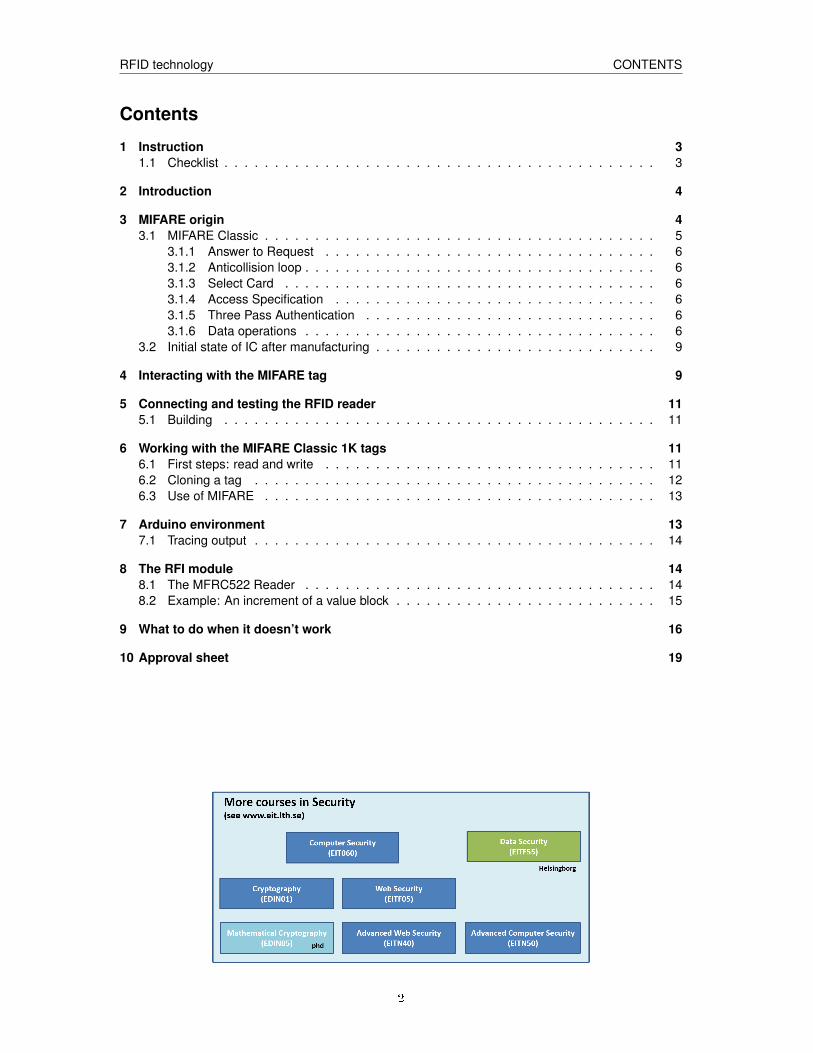
Contents
1 Instruction 31.1 Checklist . . . . . . . . . . . . . . . . . . . . . . . . . . . . . . . . . . . . . . . . . . . 3
2 Introduction 4
3 MIFARE origin 43.1 MIFARE Classic . . . . . . . . . . . . . . . . . . . . . . . . . . . . . . . . . . . . . . . 5
3.1.1 Answer to Request . . . . . . . . . . . . . . . . . . . . . . . . . . . . . . . . . 63.1.2 Anticollision loop . . . . . . . . . . . . . . . . . . . . . . . . . . . . . . . . . . . 63.1.3 Select Card . . . . . . . . . . . . . . . . . . . . . . . . . . . . . . . . . . . . . 63.1.4 Access Specification . . . . . . . . . . . . . . . . . . . . . . . . . . . . . . . . 63.1.5 Three Pass Authentication . . . . . . . . . . . . . . . . . . . . . . . . . . . . . 63.1.6 Data operations . . . . . . . . . . . . . . . . . . . . . . . . . . . . . . . . . . . 6
3.2 Initial state of IC after manufacturing . . . . . . . . . . . . . . . . . . . . . . . . . . . . 9
4 Interacting with the MIFARE tag 9
5 Connecting and testing the RFID reader 115.1 Building . . . . . . . . . . . . . . . . . . . . . . . . . . . . . . . . . . . . . . . . . . . 11
6 Working with the MIFARE Classic 1K tags 116.1 First steps: read and write . . . . . . . . . . . . . . . . . . . . . . . . . . . . . . . . . 116.2 Cloning a tag . . . . . . . . . . . . . . . . . . . . . . . . . . . . . . . . . . . . . . . . 126.3 Use of MIFARE . . . . . . . . . . . . . . . . . . . . . . . . . . . . . . . . . . . . . . . 13
7 Arduino environment 137.1 Tracing output . . . . . . . . . . . . . . . . . . . . . . . . . . . . . . . . . . . . . . . . 14
8 The RFI module 148.1 The MFRC522 Reader . . . . . . . . . . . . . . . . . . . . . . . . . . . . . . . . . . . 148.2 Example: An increment of a value block . . . . . . . . . . . . . . . . . . . . . . . . . . 15
9 What to do when it doesn’t work 16
10 Approval sheet 19
2
RFID technology Instruction
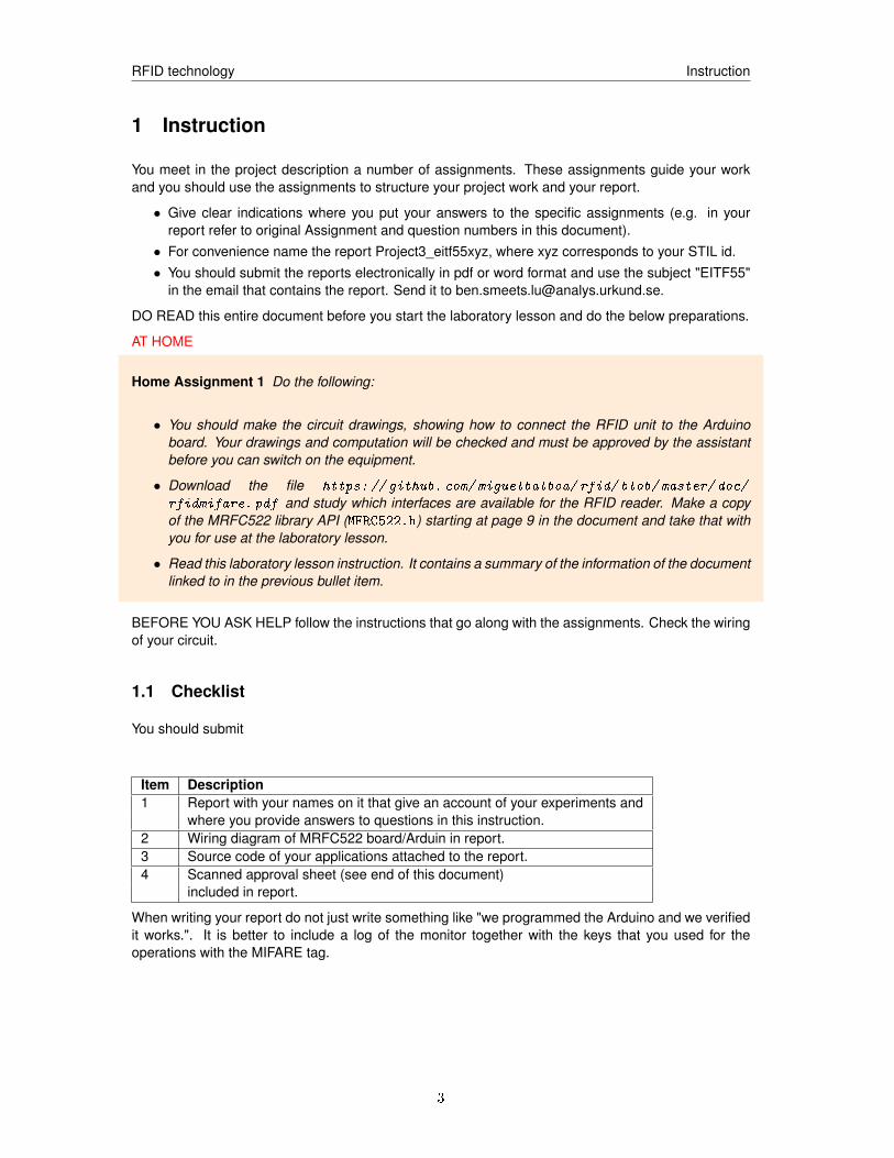
1 Instruction
You meet in the project description a number of assignments. These assignments guide your workand you should use the assignments to structure your project work and your report.
• Give clear indications where you put your answers to the specific assignments (e.g. in yourreport refer to original Assignment and question numbers in this document).
• For convenience name the report Project3_eitf55xyz, where xyz corresponds to your STIL id.• You should submit the reports electronically in pdf or word format and use the subject "EITF55"
in the email that contains the report. Send it to [email protected].
DO READ this entire document before you start the laboratory lesson and do the below preparations.
AT HOME
Home Assignment 1 Do the following:
• You should make the circuit drawings, showing how to connect the RFID unit to the Arduinoboard. Your drawings and computation will be checked and must be approved by the assistantbefore you can switch on the equipment.
• Download the file https: // github. com/ miguelbalboa/ rfid/ blob/ master/ doc/
rfidmifare. pdf and study which interfaces are available for the RFID reader. Make a copyof the MRFC522 library API (MFRC522.h) starting at page 9 in the document and take that withyou for use at the laboratory lesson.
• Read this laboratory lesson instruction. It contains a summary of the information of the documentlinked to in the previous bullet item.
BEFORE YOU ASK HELP follow the instructions that go along with the assignments. Check the wiringof your circuit.
1.1 Checklist
You should submit
Item Description1 Report with your names on it that give an account of your experiments and
where you provide answers to questions in this instruction.2 Wiring diagram of MRFC522 board/Arduin in report.3 Source code of your applications attached to the report.4 Scanned approval sheet (see end of this document)
included in report.
When writing your report do not just write something like "we programmed the Arduino and we verifiedit works.". It is better to include a log of the monitor together with the keys that you used for theoperations with the MIFARE tag.
3
RFID technology MIFARE origin
2 Introduction
In the past years we have seen a rapid growth of electronic and web services to do electronic pay-ments, access control, order goods, or keep track of goods and people. In all these services one usesat some point mechanisms to authenticate the entities involved regardless if we are talking of peopleor things or even other services. A very convenient technology that facilitates the implementation ofidentification, e-payment, utility services like energy, and e-ticketing solutions is Near Field Communi-cation (NFC). NFC technology extends the capabilities of the RFID technology developed in the 50’sby introducing storage and processing capabilities. Like RFID, the attractiveness of NFC comes fromits low cost and that devices with NFC operated with batteries and harvest their energy from the hostthey are interacting with. The most popular way to realize NFC is to use radio communication. Inthose solutions the host device, referred to as the reader, and the NFC device, referred to as the tag,each have an antenna. These antennas serve not only for the purpose of communication but alsoto transport energy from the reader to the tag to power its electronic. Today there are a number ofdifferent NFC solutions that work on this principle. Two well-known solutions are the class of MIFAREdevices and the class of Felica devices. In this laboratory lesson we look a bit closer at MIFARE,and in particular the MIFARE Classic variant which is used in contactless smart cards and proximitycards. We will throughout this laboratory instruction not really distinguish between RFID and NFCtechnologies. It allows us to align the text with an adopted praxis where some products are describedas "RFID" whereas one is actually dealing with NFC. As an excuse we can, amongst others, note thatRFID and NFC technology share some commonality in its radio technology.
The MIFARE Classic tags have been used by many organizations such as public transport suppliersor by companies that build secure facility access solutions. Today MIFARE Classic is no longer con-sidered to be secure enough for many of these purposes and more advanced NFC solutions are used.The reason for this development lies in the cryptanalysis of the MIFARE Classic that makes it possiblyto clone MIFARE Classic tags in a simple and efficient way. However, for applications where the lackof security is not an issue, the NFC capabilities may still make the MIFARE Classic tags interesting.
3 MIFARE origin
The MIFARE technology is owned by NXP Semiconductors (NXP spin off from Philips Electronics in2006) with headquarters in Eindhoven, Netherlands. The MIFARE Classic belongs to class of NFCchips widely used in contactless smart cards, proximity cards, and tags.
The MIFARE technology is based upon the ISO/IEC 14443 Type A 13.56 MHz contactless smart cardstandard. Behind the MIFARE name there are seven different kinds of contactless cards. MIFAREClassic employs a proprietary protocol compliant to parts 1 to 3 of ISO/IEC 14443-3 Type A, butdoesn’t implement part 4. Instead, the MIFARE Classic cards communicate encrypted using an NXPproprietary stream cipher, named crypto1, to provide data confidentiality and mutual authenticationbetween card and reader.
Functionally, the MIFARE Classic card provides its users with APIs to write and read data, and toperform increment and decrement operations on stored values, so called value blocks, where this datais stored in a memory that is divided into segments and blocks with simple security mechanisms foraccess control. The MIFARE Classic functionality is realized on cheap ASICs and they have limitedcomputational power. Thanks to their reliability and low cost, those cards are widely used for electronicwallets, access control, corporate ID cards, transportation or stadium ticketing.
The MIFARE Classic 1K offers 1024 bytes of data storage. This storage is split into 16 sectors; eachsector is protected by two different keys, called A and B and has its own, programmable, accessconditions. Each key can be programmed to allow operations such as reading, writing, increasing anddecreasing valueblocks, etc. There is also a MIFARE Classic variant that has 4096 bytes of storage
4
RFID technology MIFARE origin
and a MIFARE Classic mini that offers 320 bytes. Hence, the behaviour of the MIFARE Classic tags isvery limited, determined by a fixed program.
For each of these classic tag types, 16 bytes per sector are reserved for the two keys and accessconditions and cannot normally be used for user data. Also, the very first 16 bytes are read only andcontain the serial number of the card and other manufacturer data. That reduces the effective storagecapacity to 752 bytes for MIFARE Classic 1K.
The MIFARE Classic uses an NXP proprietary security protocol (Crypto1) for authentication and ci-phering. The encryption uses a 48 bit key, [2]. Since its appearance, several research groups haveworked on reverse engineering MIFARE chips and developed attacks to break keys of MIFARE Clas-sic cards. Most notably are the group around Karsten Nohl and Henryk Ploetz, who initially presentedthe reverse engineering of MIFARE Classic chips in December 2007 at the 24th Chaos ComputerCongress in Berlin, the IT security specialists from the Radboud University of Nijmegen [3] as well asthe cryptanalysis work by Nicolas T. Courtois from the University College London [4].
The Courtois attack allowed to recover the secret key of any sector of MIFARE Classic card via wirelessinteraction, within about 300 queries to the card and a computation effort below 1 sec. One of the laterpaper on attacks on the MIFARE Classic is [6] from 2015 which also contains a comparison of the,then, known attacks.
3.1 MIFARE Classic
In this section we give a brief description of the functionality of a MIFARE Classic system. For moreinformation we refer to the NXP material or the description found in the doc directory of the MFRC522library.
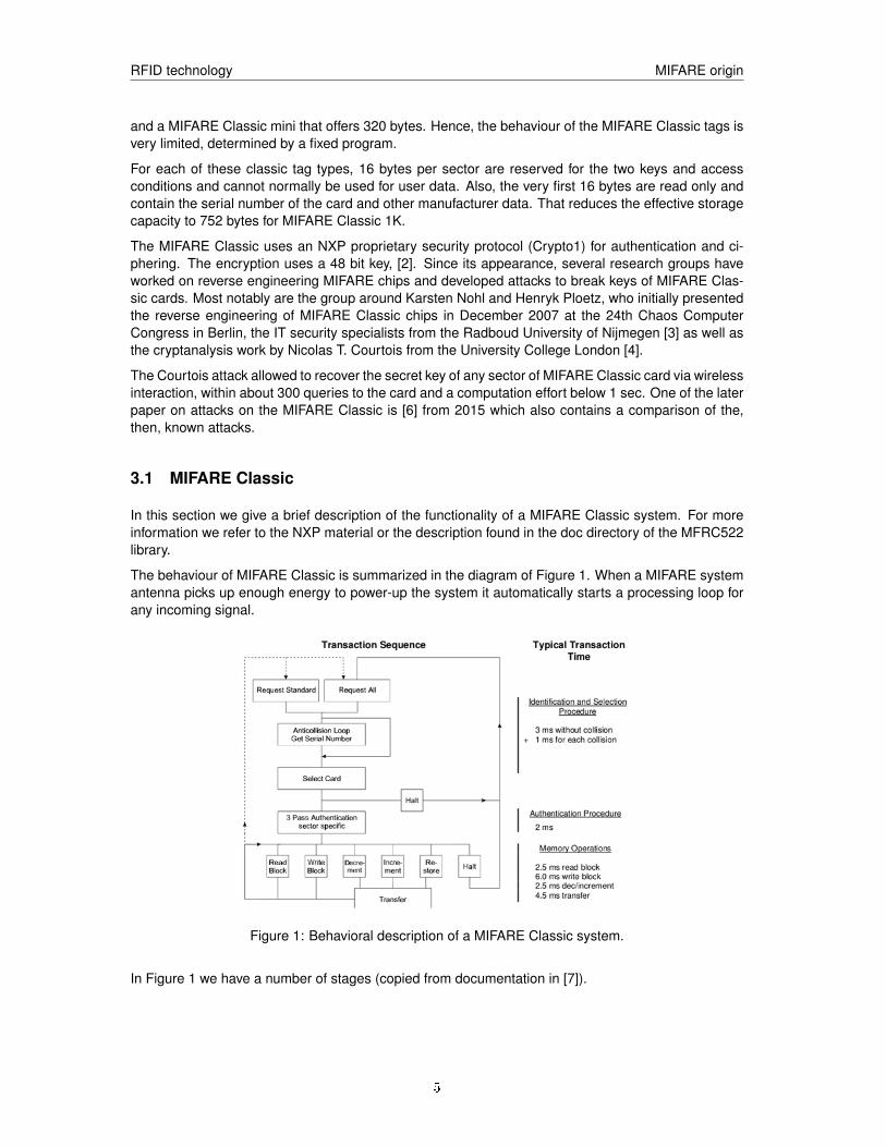
The behaviour of MIFARE Classic is summarized in the diagram of Figure 1. When a MIFARE systemantenna picks up enough energy to power-up the system it automatically starts a processing loop forany incoming signal.
Figure 1: Behavioral description of a MIFARE Classic system.
In Figure 1 we have a number of stages (copied from documentation in [7]).
5
RFID technology MIFARE origin
3.1.1 Answer to Request
With the Answer to Request sequence the MIFARE RWD (Read Write Device) requests all MIFAREcards in the antenna field. When a card is in the operating range of an RWD, the RWD continuescommunication with the appropriate protocol.
3.1.2 Anticollision loop
In the Anti-collision loop the serial number of the card is read. If there are several cards in the operatingrange of a RWD they can be distinguished by their different serial numbers and one can be selected(Select card) for further transactions. The unselected cards return to the standby mode and wait for anew Answer to Request and Anti-collision loop.
3.1.3 Select Card
With the Select Card command the RWD selects one individual card for further authentication andmemory related operations. The card returns the Answer to Select (ATS) code, which determines theindividual type of the selected card.
3.1.4 Access Specification
After identification and selection of one card the RWD specifies the memory location of the followingaccess.
3.1.5 Three Pass Authentication
The appropriate access key for the previously specified access is used for 3 Pass Authentication. Anycommunication after authentication is automatically encrypted at the sender and decrypted by thereceiver.
3.1.6 Data operations
After authentication, any of the following operations may be performed:
READ reads one block
WRITE writes one block
DECREMENT decrements the contents of one block and stores the result in the data-register
INCREMENT increments the contents of one block and stores the result in the data-register
TRANSFER writes the contents of the data-register to one block
RESTORE stores the contents of one block in the data-register
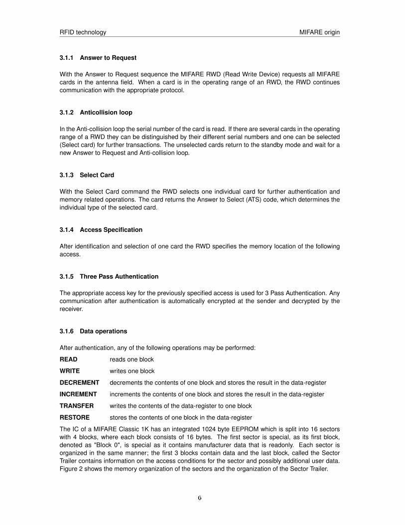
The IC of a MIFARE Classic 1K has an integrated 1024 byte EEPROM which is split into 16 sectorswith 4 blocks, where each block consists of 16 bytes. The first sector is special, as its first block,denoted as "Block 0", is special as it contains manufacturer data that is readonly. Each sector isorganized in the same manner; the first 3 blocks contain data and the last block, called the SectorTrailer contains information on the access conditions for the sector and possibly additional user data.Figure 2 shows the memory organization of the sectors and the organization of the Sector Trailer.
6
RFID technology MIFARE origin
Figure 2: Layout of the memory of MIFARE Classic 1K.
The Sector Trailer block is divided into three parts; the first part, made up by byte 0 up to and includingbyte 5, contains the bytes of Key A. Then follows 4 bytes for the access conditions, and then follows 6bytes, bytes 10 through 15, for an optional key B. The access conditions define the rules under whichdata can be read, written, incremented, decremented, transferred or restored either with Key A, Key Bor never. The organization of the 4 bytes with the access condition is shown in Figure 2 and is ratherinvolved and the details are omitted here. Note that the last byte, byte 9, of the access conditions isactually a block where the user can put data. The 6 bytes of key B can also be used for user data if noKey B is used, a condition that is encoded in the access condition bytes.
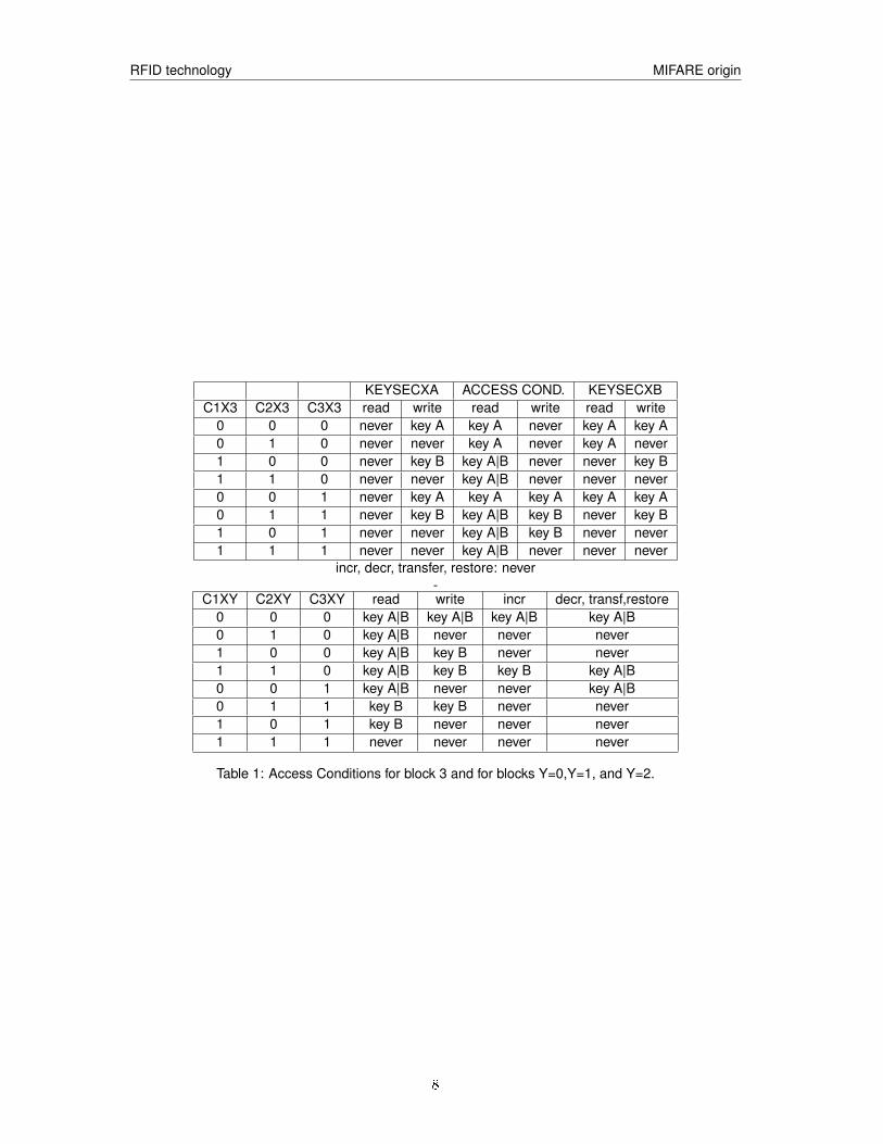
Programming the Trailer block does not require one to fully understand the encoding of the accessconditions as the programming is done through the APIs of the MFRC library. We refer the interestedreader to documentation for the MFRC library for more details. We summarize here only the mostessential facts. The access conditions for the trailer block (block3) and the data blocks (blocks 0through 2) are defined as shown in the two tables 1.
For example, if we want that we can set key A, read and write the access condition bytes, and readand write key B if we know key A, then the condition bits should be set as C1X3=0, C2X3=0, C3X3=1.Furthermore, if C1XY=C2XY=C3XY=0, for Y=0,1, and 2 we are allow any operation if key A or Key Bis known.
Before the execution of a command the correct format of the Access Conditions is checked by the Card-IC. Because any unsuccessful write operation may lead to blocking the whole sector it is importantthat during the programming of the Sector Trailer the card is kept fixed within the operating range of aRWD’s antenna to prevent interruption of the write operation.
7
RFID technology MIFARE origin
KEYSECXA ACCESS COND. KEYSECXBC1X3 C2X3 C3X3 read write read write read write
0 0 0 never key A key A never key A key A0 1 0 never never key A never key A never1 0 0 never key B key A|B never never key B1 1 0 never never key A|B never never never0 0 1 never key A key A key A key A key A0 1 1 never key B key A|B key B never key B1 0 1 never never key A|B key B never never1 1 1 never never key A|B never never never
incr, decr, transfer, restore: never-
C1XY C2XY C3XY read write incr decr, transf,restore0 0 0 key A|B key A|B key A|B key A|B0 1 0 key A|B never never never1 0 0 key A|B key B never never1 1 0 key A|B key B key B key A|B0 0 1 key A|B never never key A|B0 1 1 key B key B never never1 0 1 key B never never never1 1 1 never never never never
Table 1: Access Conditions for block 3 and for blocks Y=0,Y=1, and Y=2.
8

RFID technology Interacting with the MIFARE tag
3.2 Initial state of IC after manufacturing
A MIFARE leaves the factory in a predefined state that is shown in Figure 3 Note the serial number inblock 0 and its check byte CB. The access codes are set in a so-called transport configuration
Figure 3: Pristine memory content of Card-IC test.
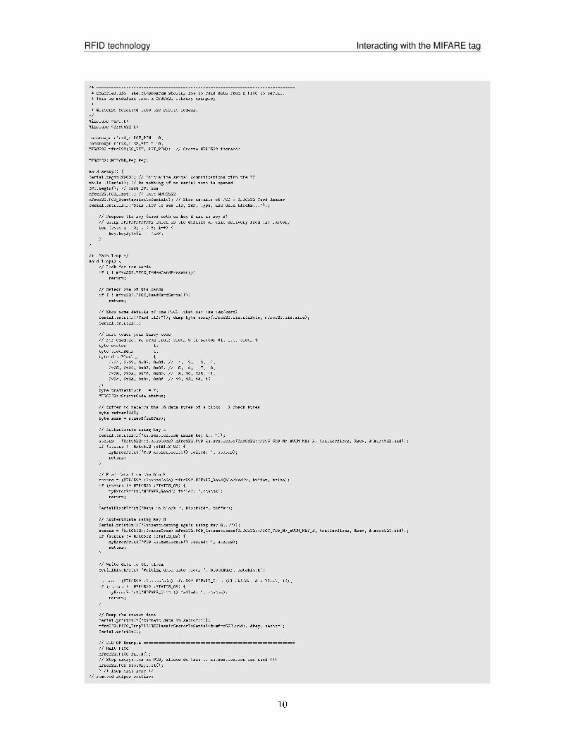
4 Interacting with the MIFARE tag
Using the MRFC522 reader IC and its library we can easily write Arduino progams that allows you tointeract with the tags. In this laboratory lesson you will use and write several of such utility programs.Basically all programs follow the code shown in the Example1.ino sketch.
9
RFID technology Interacting with the MIFARE tag
/* --------------------------------------------------------------------------------
* Example1.ino sketch/program showing how to read data from a PICC to serial.
* This is modified from a MFRC522 library example;
*
* @license Released into the public domain.
*/
#include <SPI.h>
#include <MFRC522.h>
constexpr uint8_t RST_PIN = 9;
constexpr uint8_t SS_PIN = 10;
MFRC522 mfrc522(SS_PIN, RST_PIN); // Create MFRC522 instance
MFRC522::MIFARE_Key key;
void setup() {
Serial.begin(9600); // Initialize serial communications with the PC
while (!Serial); // Do nothing if no serial port is opened
SPI.begin(); // Init SPI bus
mfrc522.PCD_Init(); // Init MFRC522
mfrc522.PCD_DumpVersionToSerial(); // Show details of PCD - MFRC522 Card Reader
Serial.println(F("Scan PICC to see UID, SAK, type, and data blocks..."));
// Prepare the key (used both as key A and as key B)
// using FFFFFFFFFFFFh which is the default at chip delivery from the factory
for (byte i = 0; i < 6; i++) {
key.keyByte[i] = 0xFF;
}
}
/* Main loop */
void loop() {
// Look for new cards
if ( ! mfrc522.PICC_IsNewCardPresent())
return;
// Select one of the cards
if ( ! mfrc522.PICC_ReadCardSerial())
return;
// Show some details of the PICC (that is: the tag/card)
Serial.print(F("Card UID:")); dump_byte_array(mfrc522.uid.uidByte, mfrc522.uid.size);
Serial.println();
// here comes your fancy code ===============================================================
// For example, we read from: block 0 in sector #1, i.e. block 4
byte sector = 1;
byte blockAddr = 4;
byte dataBlock[] = {
0x01, 0x02, 0x03, 0x04, // 1, 2, 3, 4,
0x05, 0x06, 0x07, 0x08, // 5, 6, 7, 8,
0x09, 0x0a, 0xff, 0x0b, // 9, 10, 255, 11,
0x0c, 0x0d, 0x0e, 0x0f // 12, 13, 14, 15
};
byte trailerBlock = 7;
MFRC522::StatusCode status;
// buffer to receive the 16 data bytes of a block + 2 check bytes
byte buffer[18];
byte size = sizeof(buffer);
// Authenticate using key A
Serial.println(F("Authenticating using key A..."));
status = (MFRC522::StatusCode) mfrc522.PCD_Authenticate(MFRC522::PICC_CMD_MF_AUTH_KEY_A, trailerBlock, &key, &(mfrc522.uid));
if (status != MFRC522::STATUS_OK) {
myErrorPrint("PCD_Authenticate() failed: ", status);
return;
}
// Read data from the block
status = (MFRC522::StatusCode) mfrc522.MIFARE_Read(blockAddr, buffer, &size);
if (status != MFRC522::STATUS_OK) {
myErrorPrint("MIFARE_Read() failed: ",status);
return;
}
SerialBlockPrint("Data in block ", blockAddr, buffer);
// Authenticate using key B
Serial.println(F("Authenticating again using key B..."));
status = (MFRC522::StatusCode) mfrc522.PCD_Authenticate(MFRC522::PICC_CMD_MF_AUTH_KEY_B, trailerBlock, &key, &(mfrc522.uid));
if (status != MFRC522::STATUS_OK) {
myErrorPrint("PCD_Authenticate() failed: ", status);
return;
}
// Write data to the block
SerialBlockPrint("Writing data into block ", blockAddr, dataBlock);
status = (MFRC522::StatusCode) mfrc522.MIFARE_Write(blockAddr, dataBlock, 16);
if (status != MFRC522::STATUS_OK) {
myErrorPrint("MIFARE_Write() failed: ", status);
return;
}
// Dump the sector data
Serial.println(F("Current data in sector:"));
mfrc522.PICC_DumpMIFAREClassicSectorToSerial(&(mfrc522.uid), &key, sector);
Serial.println();
// END OF Example =============================================================
// Halt PICC
mfrc522.PICC_HaltA();
// Stop encryption on PCD, always do this if authentication was used !!!
mfrc522.PCD_StopCrypto1();
} /* loop ends here */
// removed helper routines
10
RFID technology Working with the MIFARE Classic 1K tags
5 Connecting and testing the RFID reader
5.1 Building
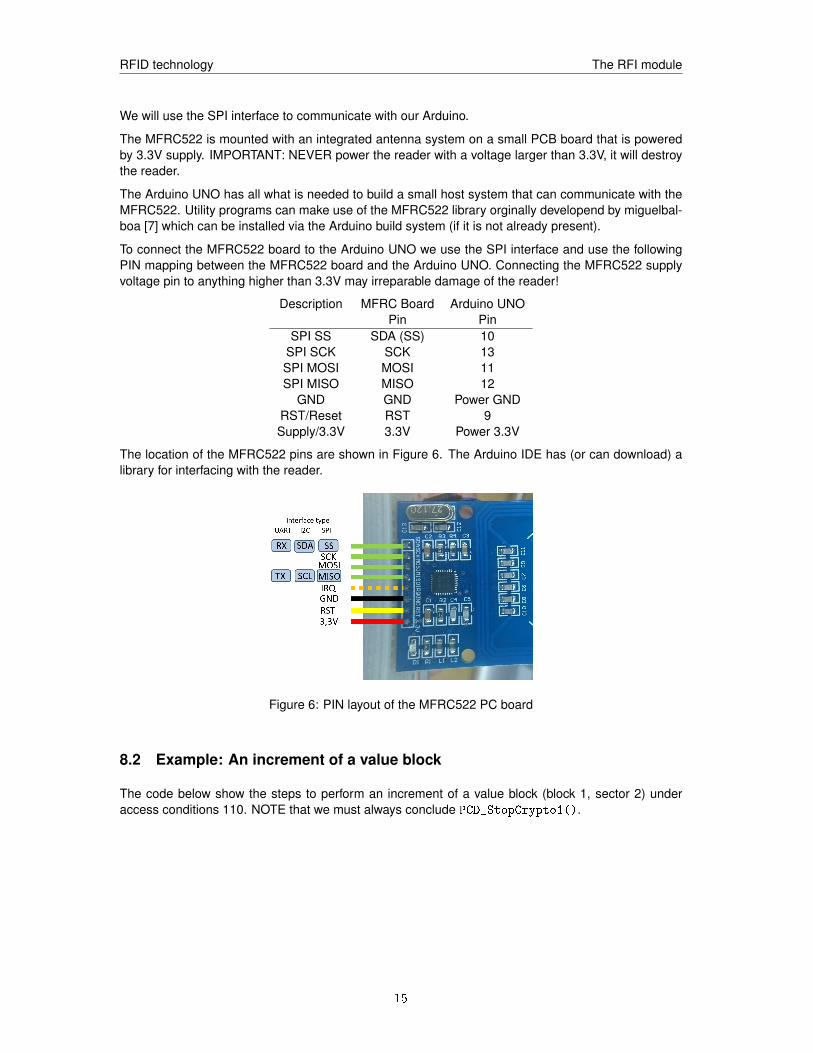
Now it is time for you to build a complete tag reading reader system using the MFRC522. Put theMFRC522 PC board on a breadboard. Locate the exact orientation of its pins, Figure 6 This is crucialas the MFRC522 is operated at 3.3V and using a larger voltage destroys the chip, so be careful.
Assignment 1 Take the circuit drawing that you prepared at home which shows how to connect to theArduino unit to the MFRC522 board. Before, connecting the Arduino UNO to the PC and power thesystem up, let the laboratory assistant check your wiring in your build.
Next you connect the USB port of the Arduino to you PC and fire-up the Arduino IDE code developertool. You need a MFRC522 library to interact with the MFRC522 reader. This should be alreadyavailable or can be downloaded via the IDE system.
Assignment 2 Download or locate the DumpInfo.ino1 project to your computer and open it in theIDE. Check that the IDE is properly configured to talk with your Arduino. Compile and download thedump protocol to the Arduino UNO. Open the serial port monitor so you can see the output that theArduino produces.
Now take a blue MIFARE tag and hold it close to the reader. In the monitor window you should seenow a printout of some information like the serial number and a dump of the 16 sectors. You can seehow part of the content of block 0 matches the serial number.
Collect the dump for inclusion in your lab report.
Before calling help:If you do not get output, check the wiring and that you can you can run the program that dumps the
tag contents.
6 Working with the MIFARE Classic 1K tags
6.1 First steps: read and write
It this point you have a working reader system that can interact with the MIFARE Classic tags. Younow have to program a tag; first we just program a user data block in any sector between 1 and 15(that is we do no work with sector 0), and after that we also program its sector trailer block. In whatfollows we assume we use sector 2 but you can use any other sector that is available.
Assignment 3 To read and write on block 0 of sector 2 (is block 8)we must authenticate with Key Asince the access condition is set to [001]. The key is set at manufacturing time to ’FFFFFFFFFFFF’.Take the code from the Example1.ino sketch and modify it so that you read block 8, write the hexdata
{ 0x2D, 0x20, 0x48, 0x65, 0x6A, 0x61, 0x20, 0x45,
0x49, 0x54, 0x46, 0x35, 0x35, 0x20, 0x2D, 0x00}
to block 8, the least significant byte is to the left, i.e. 0x2D. Next, read the block 8 into a variable ’buffer’and write the buffer with the data as a string by using:
11
RFID technology Working with the MIFARE Classic 1K tags
Serial.println((char*)buffer);
Document your work in the report.
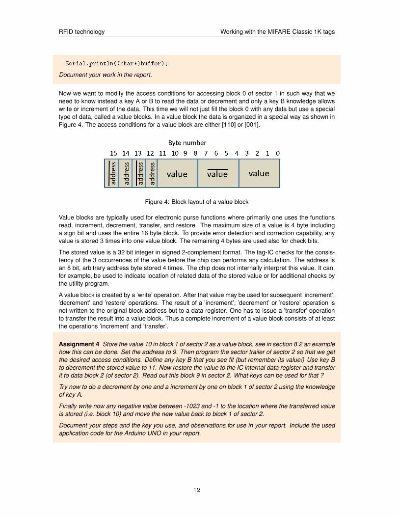
Now we want to modify the access conditions for accessing block 0 of sector 1 in such way that weneed to know instead a key A or B to read the data or decrement and only a key B knowledge allowswrite or increment of the data. This time we will not just fill the block 0 with any data but use a specialtype of data, called a value blocks. In a value block the data is organized in a special way as shown inFigure 4. The access conditions for a value block are either [110] or [001].
Figure 4: Block layout of a value block
Value blocks are typically used for electronic purse functions where primarily one uses the functionsread, increment, decrement, transfer, and restore. The maximum size of a value is 4 byte includinga sign bit and uses the entire 16 byte block. To provide error detection and correction capability, anyvalue is stored 3 times into one value block. The remaining 4 bytes are used also for check bits.
The stored value is a 32 bit integer in signed 2-complement format. The tag-IC checks for the consis-tency of the 3 occurrences of the value before the chip can performs any calculation. The address isan 8 bit, arbitrary address byte stored 4 times. The chip does not internally interpret this value. It can,for example, be used to indicate location of related data of the stored value or for additional checks bythe utility program.
A value block is created by a ’write’ operation. After that value may be used for subsequent ’increment’,’decrement’ and ’restore’ operations. The result of a ’increment’, ’decrement’ or ’restore’ operation isnot written to the original block address but to a data register. One has to issue a ’transfer’ operationto transfer the result into a value block. Thus a complete increment of a value block consists of at leastthe operations ’increment’ and ’transfer’.
Assignment 4 Store the value 10 in block 1 of sector 2 as a value block, see in section 8.2 an examplehow this can be done. Set the address to 9. Then program the sector trailer of sector 2 so that we getthe desired access conditions. Define any key B that you see fit (but remember its value!) Use key Bto decrement the stored value to 11. Now restore the value to the IC internal data register and transferit to data block 2 (of sector 2). Read out this block 9 in sector 2. What keys can be used for that ?
Try now to do a decrement by one and a increment by one on block 1 of sector 2 using the knowledgeof key A.
Finally write now any negative value between -1023 and -1 to the location where the transferred valueis stored (i.e. block 10) and move the new value back to block 1 of sector 2.
Document your steps and the key you use, and observations for use in your report. Include the usedapplication code for the Arduino UNO in your report.
12
RFID technology Arduino environment
6.2 Cloning a tag
Since we can read and write from a tag one is close to be able to clone a tag. In practice this requiresus to get access to the keys. This is possible for the MIFARE Classic cards using some more specialequipment that gives better control over the interaction with the card. Here we just try to see if some ofwell-known keys are used on the target tag that we want to clone. We use here the program from theMFRC522 library repository. During the preparation you should have studied how this program worksand now it is time to use it.
Assignment 5 Compile and load the code from the RFID-Cloner.ino project2 into your system andtry to clone the tag you programmed before. Document your observations in your report.
Answer in you report the following question: Since, a MIFARE Classic tag has block 0 only as read-onlywhy we can still say that we can clone a such a tag?
6.3 Use of MIFARE
Since we can clone MIFARE Classic cards they, strictly speaking, give no longer any security. Is thereanything we can do here to make this better? Unfortunately, the answer to this question is in generalnegative. The fact that one can extract all data from the card and that one knows how the card worksmakes it impossible to stop cloning which undermines the basic use of the MIFARE Classic cards asmeans for authentication. What is also cumbersome is the fact that the user of the tag normally cannotprevent that his/her tag is challenged by an hostile host system. To prevent the latter the user has tokeep the tag in a place where it cannot be triggered.
On can combine the use of the tag with other security features like entering a PIN, whose hash,properly salted, is stored on the tag. This doesn’t prevent cloning of course but prevents that the tagcan be used without proper ownership. On the other hand such a remedy destroys the major use-caseof the tag which is ease of use and low cost. PIN entrance is not always convenient and since itrequires a keypad for entering the PIN such a solution inquires additional cost on the overall system.
On the other hand, provided properly configured, a MIFARE Classic tag can still be a useful andconvenient device to protect against casual or unintentional modifications.
Furthermore, when the tags are used in a system that continuously is able to monitor tags, it may bepossible to detect clones from being used and disable tags with that specific serial number.
Assignment 6 Discuss in your report how you could use MIFARE Classic tags in a door accesscontrol system where all door RFID readers are connected to a central system. Discuss pros andcons of your system. Use not more than one page for answering this assignment.
7 Arduino environment
We use one Arduino UNO controller that we program from a Lab PC. The controller is connected tothe Lab PC using a USB cable. The PC communicates with the Arduino via a serial TTY interfacerunning over USB and you must check in the IDE that the right interface is selected
The Arduino IDE environment should already be installed on your lab PC. So do not do that again. Ifthis laboratory is the first time you work with an Arduino and its development environment it is goodthat you first watch some of the tutorials on Youtube to get a quick introduction, e.g. https://www.
13
RFID technology The RFI module
youtube.com/watch?v=fCxzA9_kg6s or https://www.youtube.com/watch?v=kLd_JyvKV4Y. Formore guidance on the use the Arduino environment look at [8].
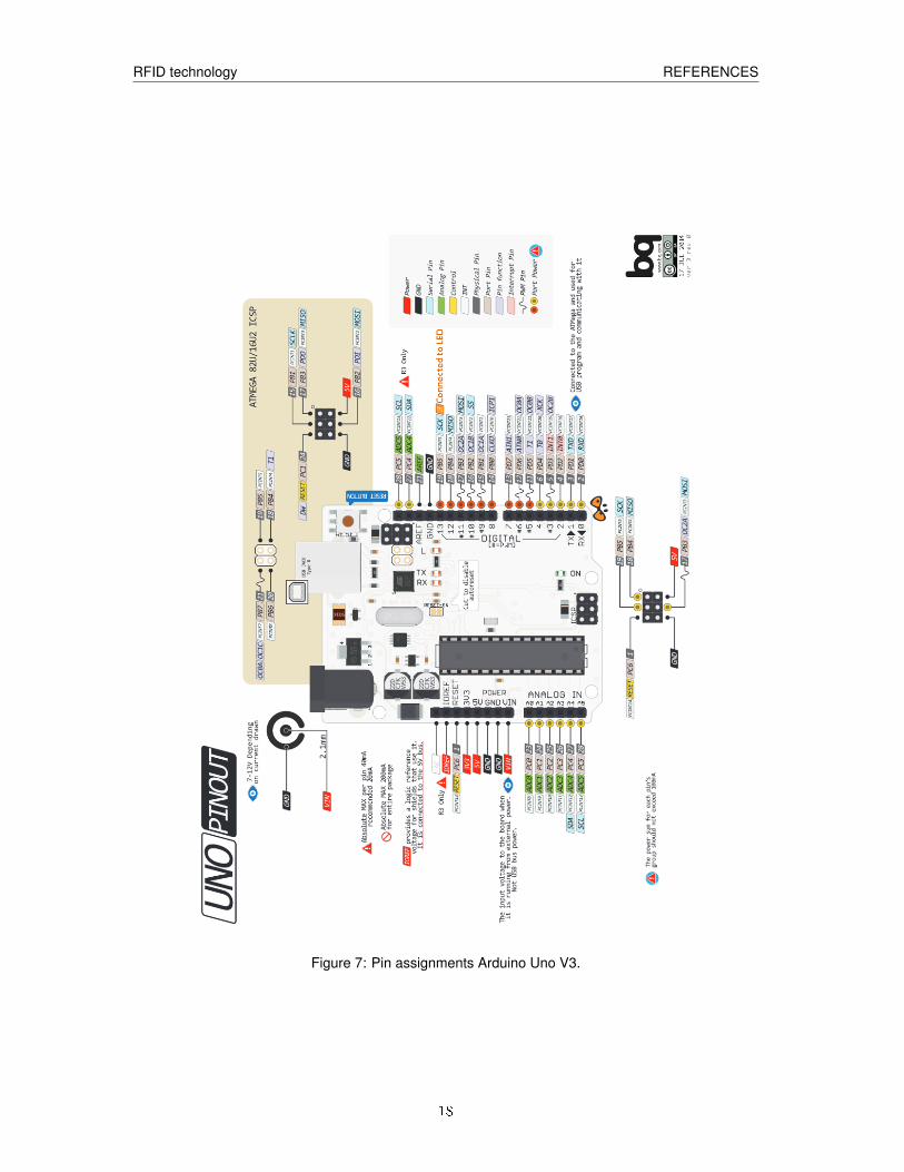
We will use the Arduino UNO V3 controller for which the Pin assignments are shown in Figure 7. Wepower the Arduino units via the USB so no external power source is needed. More information on theArduino Uno controller can be found at [9].
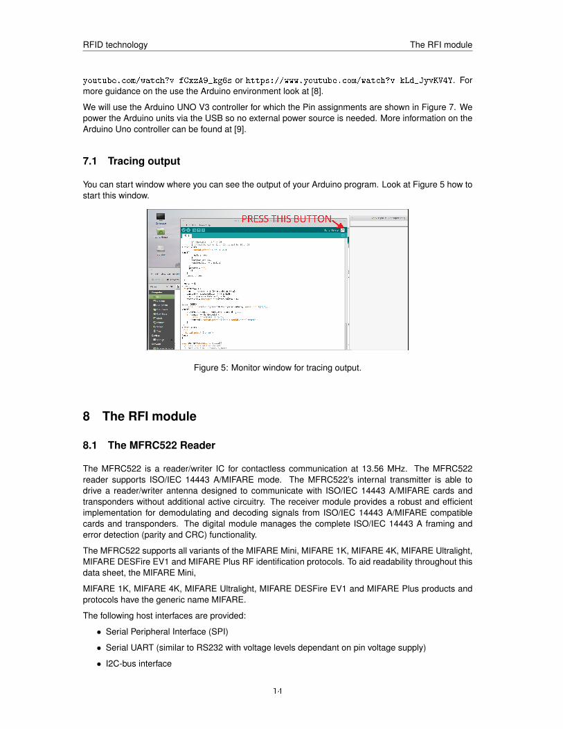
7.1 Tracing output
You can start window where you can see the output of your Arduino program. Look at Figure 5 how tostart this window.
Figure 5: Monitor window for tracing output.
8 The RFI module
8.1 The MFRC522 Reader
The MFRC522 is a reader/writer IC for contactless communication at 13.56 MHz. The MFRC522reader supports ISO/IEC 14443 A/MIFARE mode. The MFRC522’s internal transmitter is able todrive a reader/writer antenna designed to communicate with ISO/IEC 14443 A/MIFARE cards andtransponders without additional active circuitry. The receiver module provides a robust and efficientimplementation for demodulating and decoding signals from ISO/IEC 14443 A/MIFARE compatiblecards and transponders. The digital module manages the complete ISO/IEC 14443 A framing anderror detection (parity and CRC) functionality.
The MFRC522 supports all variants of the MIFARE Mini, MIFARE 1K, MIFARE 4K, MIFARE Ultralight,MIFARE DESFire EV1 and MIFARE Plus RF identification protocols. To aid readability throughout thisdata sheet, the MIFARE Mini,
MIFARE 1K, MIFARE 4K, MIFARE Ultralight, MIFARE DESFire EV1 and MIFARE Plus products andprotocols have the generic name MIFARE.
The following host interfaces are provided:
• Serial Peripheral Interface (SPI)
• Serial UART (similar to RS232 with voltage levels dependant on pin voltage supply)
• I2C-bus interface
14
RFID technology The RFI module
We will use the SPI interface to communicate with our Arduino.
The MFRC522 is mounted with an integrated antenna system on a small PCB board that is poweredby 3.3V supply. IMPORTANT: NEVER power the reader with a voltage larger than 3.3V, it will destroythe reader.
The Arduino UNO has all what is needed to build a small host system that can communicate with theMFRC522. Utility programs can make use of the MFRC522 library orginally developend by miguelbal-boa [7] which can be installed via the Arduino build system (if it is not already present).
To connect the MFRC522 board to the Arduino UNO we use the SPI interface and use the followingPIN mapping between the MFRC522 board and the Arduino UNO. Connecting the MFRC522 supplyvoltage pin to anything higher than 3.3V may irreparable damage of the reader!
Description MFRC Board Arduino UNOPin Pin
SPI SS SDA (SS) 10SPI SCK SCK 13SPI MOSI MOSI 11SPI MISO MISO 12
GND GND Power GNDRST/Reset RST 9Supply/3.3V 3.3V Power 3.3V
The location of the MFRC522 pins are shown in Figure 6. The Arduino IDE has (or can download) alibrary for interfacing with the reader.
Figure 6: PIN layout of the MFRC522 PC board
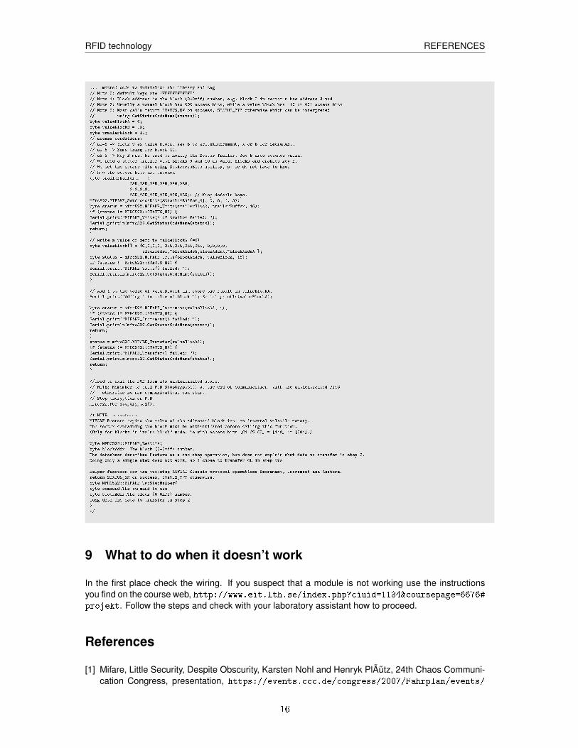
8.2 Example: An increment of a value block
The code below show the steps to perform an increment of a value block (block 1, sector 2) underaccess conditions 110. NOTE that we must always conclude PCD_StopCrypto1().
15
RFID technology REFERENCES
... omitted code to initialize the library and tag
// Note 0: default keys are 'FFFFFFFFFFFF'
// Note 1: Block address is the block (0-0xff) number, e.g. block 3 in sector n has address 3+n*4
// Note 2: Usually a normal block has 000 access bits, while a value block has 110 or 001 access bits
// Note 3: Most calls return STATUS_OK on success, STATUS_??? otherwise which can be interpreted
// using GetStatusCodeName(status));
byte valueBlockA = 9;
byte valueBlockB = 10;
byte trailerBlock = 11;
// access conditions:
// a1=6 => block 9 as value block. Key B to write&increment, A or B for decrement.
// a2=6 => Same thing for block 10.
// a3=3 => Key B must be used to modify the Sector Trailer. Key B area becomes valid.
// We need a sector trailer with blocks 9 and 10 as Value Blocks and enables key B.
// We set the access bits using SetAccessBits utility, so we do not have to know
// how the access bits are encoded
byte trailerBuffer[] = {
255,255,255,255,255,255,
0,0,0,0,
255,255,255,255,255,255}; // Keep default keys.
mfrc522.MIFARE_SetAccessBits(&trailerBuffer[6], 0, 6, 6, 3);
byte status = mfrc522.MIFARE_Write(trailerBlock, trailerBuffer, 16);
if (status != MFRC522::STATUS_OK) {
Serial.print("MIFARE_Write() of trailor failed: ");
Serial.println(mfrc522.GetStatusCodeName(status));
return;
}
// write a value of zero to valueBlockA (=9)
byte valueBlock[] = {0,0,0,0, 255,255,255,255, 0,0,0,0,
blockAddrA,~blockAddrA,blockAddrA,~blockAddrA };
byte status = mfrc522.MIFARE_Write(blockAddrA, valueBlock, 16);
if (status != MFRC522::STATUS_OK) {
Serial.print("MIFARE_Write() failed: ");
Serial.println(mfrc522.GetStatusCodeName(status));
}
// Add 1 to the value of valueBlockA and store the result in valueBlockA.
Serial.print("Adding 1 to value of block "); Serial.println(valueBlockA);
byte status = mfrc522.MIFARE_Increment(valueBlockA, 1);
if (status != MFRC522::STATUS_OK) {
Serial.print("MIFARE_Increment() failed: ");
Serial.println(mfrc522.GetStatusCodeName(status));
return;
}
status = mfrc522.MIFARE_Transfer(valueBlockA);
if (status != MFRC522::STATUS_OK) {
Serial.print("MIFARE_Transfer() failed: ");
Serial.println(mfrc522.GetStatusCodeName(status));
return;
}
//Used to exit the PCD from its authenticated state.
// NOTE: Remember to call PCD_StopCrypto1() at the end of communication with the authenticated PICC
// - otherwise no new communications can start.
// Stop encryption on PCD
mfrc522.PCD_StopCrypto1();
/* NOTE on restore:
MIFARE Restore copies the value of the addressed block into an internal volatile memory.
The sector containing the block must be authenticated before calling this function.
(Only for blocks in "value block" mode, ie with access bits [C1 C2 C3] = [110] or [001].)
byte MFRC522::MIFARE_Restore(
byte blockAddr The block (0-0xff) number.
The datasheet describes Restore as a two step operation, but does not explain what data to transfer in step 2.
Doing only a single step does not work, so I chose to transfer 0L in step two.
Helper function for the two-step MIFARE Classic protocol operations Decrement, Increment and Restore.
return STATUS_OK on success, STATUS_??? otherwise.
byte MFRC522::MIFARE_TwoStepHelper(
byte command,The command to use
byte blockAddr,The block (0-0xff) number.
long data The data to transfer in step 2
)
*/
9 What to do when it doesn’t work
In the first place check the wiring. If you suspect that a module is not working use the instructionsyou find on the course web, http://www.eit.lth.se/index.php?ciuid=1134&coursepage=6676#projekt. Follow the steps and check with your laboratory assistant how to proceed.
References
[1] Mifare, Little Security, Despite Obscurity, Karsten Nohl and Henryk PlÃutz, 24th Chaos Communi-cation Congress, presentation, https://events.ccc.de/congress/2007/Fahrplan/events/
16
RFID technology REFERENCES
2378.en.html.
[2] Cryptanalysis of Crypto-1. Karsten Nohl.http://www.cs.virginia.edu/~kn5f/Mifare.Cryptanalysis.htm, 2012. [checked 2018].
[3] Dismantling MIFARE Classic, Flavio D. Garcia, et all, ESORICS 2008, LNCS 5283, pp. 97âAS114,2008.
[4] THE DARK SIDE OF SECURITY BY OBSCURITY and Cloning MiFare Classic Rail and BuildingPasses, Anywhere, Anytime. Nicolas T. Courtois. Cryptology ePrint Archive, 2009.
[5] libnfc.org- Public platform independent Near Field Communication (NFC) library. Roel Verdult.http://www.libnfc.org, July 2011.
[6] Ciphertext-only Cryptanalysis on Hardened Mifare Classic Cards, Carlo Meijer & Roel Verdult,CCS 2015.
[7] miguelbalboa’s Arduino library for MFRC522 and other RFID RC522 based modules. https://github.com/miguelbalboa/rfid
[8] https://www.arduino.cc/en/Guide/HomePage
[9] https://www.arduino.cc/en/Main/ArduinoBoardUno
17
RFID technology REFERENCES
Figure 7: Pin assignments Arduino Uno V3.
18
RFID technology Approval sheet
10 Approval sheet
On this sheet you assistant will sign-off that did the necessary preparations prior to start the projectin the laboratory rooms. You are NOT allowed to switch the equipment on before he/she has checkedthis and gives an OK to proceed.
The assistant also checks and records on this sheet if you got your implementations properly working.
SCAN this page and include the scan of your group’s approval sheet in your report.
Date:Your name 1:
Your name 2:
Item ApprovedWiring drawing MRFC522 and coupling to Arduino ........Print out of MFRC522 API (commands) .......
19


![J-SAFE3 on ST31G480 Security Target - Public Version · MIFARE DESFire EV1 and MIFARE Plus X – Security Tar get for composition, Rev A04.1 April 2017. [MntRep_ST31G480] ST31G480](https://img.pdfslide.us/doc/110x75/5f816eba8399b4174e615c92/j-safe3-on-st31g480-security-target-public-version-mifare-desfire-ev1-and-mifare.jpg)