Embed Size (px)
Citation preview
AMD64 VirtualizationTechnology
Secure Virtual MachineArchitecture
Reference Manual
Publication No. Revision Date
33047 3.02 December 2005
Advanced Micro Devices
Secure Virtual Machine Architecture Reference Manual 33047–Rev. 3.02–December 2005
TrademarksAMD, the AMD Arrow logo, AMD Athlon, AMD Opteron, and combinations thereof, are trademarks, and AMD-K6 is a registered trade-mark of Advanced Micro Devices, Inc.HyperTransport is a licensed trademark of the HyperTransport Technology Consortium.Pentium is a registered trademark of Intel Corporation.Other product names used in this publication are for identification purposes only and may be trademarks of their respective companies.
© 2005 Advanced Micro Devices, Inc. All rights reserved.The contents of this document are provided in connection with Advanced Micro Devices, Inc.(“AMD”) products. AMD makes no representations or warranties with respect to the accuracy orcompleteness of the contents of this publication and reserves the right to make changes tospecifications and product descriptions at any time without notice. No license, whether express,implied, arising by estoppel or otherwise, to any intellectual property rights is granted by thispublication. Except as set forth in AMD’s Standard Terms and Conditions of Sale, AMD assumesno liability whatsoever, and disclaims any express or implied warranty, relating to its productsincluding, but not limited to, the implied warranty of merchantability, fitness for a particular pur-pose, or infringement of any intellectual property right.
AMD’s products are not designed, intended, authorized or warranted for use as components insystems intended for surgical implant into the body, or in other applications intended to supportor sustain life, or in any other application in which the failure of AMD’s product could create asituation where personal injury, death, or severe property or environmental damage may occur.AMD reserves the right to discontinue or make changes to its products at any time withoutnotice.
Contents iii
33047—Rev. 3.02—December 2005 Secure Virtual Machine Architecture Reference Manual
Contents
Revision History . . . . . . . . . . . . . . . . . . . . . . . . . . . . . . . . . . . . . . . . . .xiii
Preface . . . . . . . . . . . . . . . . . . . . . . . . . . . . . . . . . . . . . . . . . . . . . . . . . . xv
1 Introduction . . . . . . . . . . . . . . . . . . . . . . . . . . . . . . . . . . . . . . . . . 1
1.1 The Virtual Machine Monitor . . . . . . . . . . . . . . . . . . . . . . . . . . 11.2 SVM Hardware Overview. . . . . . . . . . . . . . . . . . . . . . . . . . . . . . 1
Virtualization Support . . . . . . . . . . . . . . . . . . . . . . . . . . . . . . . . 1Guest Mode . . . . . . . . . . . . . . . . . . . . . . . . . . . . . . . . . . . . . . . . . 2External Access Protection . . . . . . . . . . . . . . . . . . . . . . . . . . . . 2Tagged TLB . . . . . . . . . . . . . . . . . . . . . . . . . . . . . . . . . . . . . . . . . 2Interrupt Support . . . . . . . . . . . . . . . . . . . . . . . . . . . . . . . . . . . . 2
Intercepting physical interrupt delivery . . . . . . . . . . . . . 2Virtual interrupts . . . . . . . . . . . . . . . . . . . . . . . . . . . . . . . . 2Sharing a physical APIC. . . . . . . . . . . . . . . . . . . . . . . . . . . 2
Restartable Instructions . . . . . . . . . . . . . . . . . . . . . . . . . . . . . . . 2Security Support . . . . . . . . . . . . . . . . . . . . . . . . . . . . . . . . . . . . . 2
Attestation. . . . . . . . . . . . . . . . . . . . . . . . . . . . . . . . . . . . . . 3Memory Clear. . . . . . . . . . . . . . . . . . . . . . . . . . . . . . . . . . . . 3
2 SVM Processor and Platform Extensions . . . . . . . . . . . . . . . . . 5
2.1 Enabling SVM . . . . . . . . . . . . . . . . . . . . . . . . . . . . . . . . . . . . . . . 52.2 VMRUN Instruction . . . . . . . . . . . . . . . . . . . . . . . . . . . . . . . . . . 5
Basic Operation . . . . . . . . . . . . . . . . . . . . . . . . . . . . . . . . . . . . . . 6Saving Host State . . . . . . . . . . . . . . . . . . . . . . . . . . . . . . . . 7Loading Guest State . . . . . . . . . . . . . . . . . . . . . . . . . . . . . . 7Control Bits . . . . . . . . . . . . . . . . . . . . . . . . . . . . . . . . . . . . . 8Segment State in the VMCB . . . . . . . . . . . . . . . . . . . . . . . 9Canonicalization and Consistency Checks . . . . . . . . . . . 10VMRUN and TF/RF bits in EFLAGS . . . . . . . . . . . . . . . 11
2.3 #VMEXIT . . . . . . . . . . . . . . . . . . . . . . . . . . . . . . . . . . . . . . . . . . 122.4 Intercept Operation . . . . . . . . . . . . . . . . . . . . . . . . . . . . . . . . . 13
Exception intercepts. . . . . . . . . . . . . . . . . . . . . . . . . . . . . 13Instruction intercepts . . . . . . . . . . . . . . . . . . . . . . . . . . . . 14
State Saved on Exit . . . . . . . . . . . . . . . . . . . . . . . . . . . . . . . . . . 14Intercepts During IDT Interrupt Delivery . . . . . . . . . . . . . . . 14EXITINTINFO Pseudo-Code . . . . . . . . . . . . . . . . . . . . . . . . . . 16
2.5 Instruction Intercepts . . . . . . . . . . . . . . . . . . . . . . . . . . . . . . . . 17Read/Write of CR0 . . . . . . . . . . . . . . . . . . . . . . . . . . . . . . . . . . 17Read/Write of CR3 (excluding task switch) . . . . . . . . . . . . . . 17Read/Write of other CRs . . . . . . . . . . . . . . . . . . . . . . . . . . . . . 17Read/Write of Debug Registers, DRn . . . . . . . . . . . . . . . . . . . 17Selective CR0 Write Intercept . . . . . . . . . . . . . . . . . . . . . . . . . 18Reading/Writing of IDTR, GDTR, LDTR, TR . . . . . . . . . . . . . 18
iv Contents
Secure Virtual Machine Architecture Reference Manual 33047—Rev. 3.02—December 2005
RDTSC Instruction Intercept . . . . . . . . . . . . . . . . . . . . . . . . . . 18RDPMC Instruction Intercept . . . . . . . . . . . . . . . . . . . . . . . . . 18PUSHF Instruction Intercept . . . . . . . . . . . . . . . . . . . . . . . . . . 18POPF Instruction Intercept . . . . . . . . . . . . . . . . . . . . . . . . . . . 18CPUID Instruction Intercept . . . . . . . . . . . . . . . . . . . . . . . . . . 18RSM Instruction Intercept . . . . . . . . . . . . . . . . . . . . . . . . . . . . 19IRET Instruction Intercept. . . . . . . . . . . . . . . . . . . . . . . . . . . . 19Software Interrupt Intercept . . . . . . . . . . . . . . . . . . . . . . . . . . 19INVD Instruction Intercept . . . . . . . . . . . . . . . . . . . . . . . . . . . 19PAUSE Instruction Intercept . . . . . . . . . . . . . . . . . . . . . . . . . . 19HLT Instruction Intercept. . . . . . . . . . . . . . . . . . . . . . . . . . . . . 19INVLPG Instruction Intercept . . . . . . . . . . . . . . . . . . . . . . . . . 19INVLPGA Instruction Intercept. . . . . . . . . . . . . . . . . . . . . . . . 19VMRUN Instruction Intercept . . . . . . . . . . . . . . . . . . . . . . . . . 19VMLOAD Instruction Intercept . . . . . . . . . . . . . . . . . . . . . . . . 19VMSAVE Instruction Intercept . . . . . . . . . . . . . . . . . . . . . . . . 20VMMCALL Instruction Intercept . . . . . . . . . . . . . . . . . . . . . . 20STGI Instruction Intercept . . . . . . . . . . . . . . . . . . . . . . . . . . . . 20CLGI Instruction Intercept. . . . . . . . . . . . . . . . . . . . . . . . . . . . 20SKINIT Instruction Intercept . . . . . . . . . . . . . . . . . . . . . . . . . . 20RDTSCP Instruction Intercept. . . . . . . . . . . . . . . . . . . . . . . . . 20ICEBP Instruction Intercept. . . . . . . . . . . . . . . . . . . . . . . . . . . 20WBINVD Instruction Intercept . . . . . . . . . . . . . . . . . . . . . . . . 20
2.6 IOIO Intercepts . . . . . . . . . . . . . . . . . . . . . . . . . . . . . . . . . . . . . 20I/O Permissions Map . . . . . . . . . . . . . . . . . . . . . . . . . . . . . 20IN and OUT Behavior . . . . . . . . . . . . . . . . . . . . . . . . . . . . 21I/O Intercept Information. . . . . . . . . . . . . . . . . . . . . . . . . 21
2.7 MSR Intercepts . . . . . . . . . . . . . . . . . . . . . . . . . . . . . . . . . . . . . 22MSR Permissions Map . . . . . . . . . . . . . . . . . . . . . . . . . . . 22RDMSR and WRMSR Behavior . . . . . . . . . . . . . . . . . . . . 23MSR Intercept Information . . . . . . . . . . . . . . . . . . . . . . . 23
2.8 Exception Intercepts. . . . . . . . . . . . . . . . . . . . . . . . . . . . . . . . . 23Example: . . . . . . . . . . . . . . . . . . . . . . . . . . . . . . . . . . . . . . 24
#DE (Divide By Zero) . . . . . . . . . . . . . . . . . . . . . . . . . . . . . . . . 24#DB (Debug). . . . . . . . . . . . . . . . . . . . . . . . . . . . . . . . . . . . . . . . 24Vector 2 (Reserved). . . . . . . . . . . . . . . . . . . . . . . . . . . . . . . . . . 25#BP (Breakpoint) . . . . . . . . . . . . . . . . . . . . . . . . . . . . . . . . . . . . 25#OF (Overflow) . . . . . . . . . . . . . . . . . . . . . . . . . . . . . . . . . . . . . 25#BR (Bound-Range). . . . . . . . . . . . . . . . . . . . . . . . . . . . . . . . . . 25#UD (Invalid Opcode) . . . . . . . . . . . . . . . . . . . . . . . . . . . . . . . . 25#NM (Device-Not-Available). . . . . . . . . . . . . . . . . . . . . . . . . . . 25#DF (Double Fault) . . . . . . . . . . . . . . . . . . . . . . . . . . . . . . . . . . 25Vector 9 (Reserved). . . . . . . . . . . . . . . . . . . . . . . . . . . . . . . . . . 25#TS (Invalid TSS). . . . . . . . . . . . . . . . . . . . . . . . . . . . . . . . . . . . 25#NP (Segment Not Present) . . . . . . . . . . . . . . . . . . . . . . . . . . . 25#SS (Stack Fault) . . . . . . . . . . . . . . . . . . . . . . . . . . . . . . . . . . . . 25#GP (General Protection) . . . . . . . . . . . . . . . . . . . . . . . . . . . . . 26
Contents v
33047—Rev. 3.02—December 2005 Secure Virtual Machine Architecture Reference Manual
#PF (Page Fault) . . . . . . . . . . . . . . . . . . . . . . . . . . . . . . . . . . . . 26#MF (X87 Floating Point) . . . . . . . . . . . . . . . . . . . . . . . . . . . . . 26#AC (Alignment Check) . . . . . . . . . . . . . . . . . . . . . . . . . . . . . . 26#MC (Machine Check). . . . . . . . . . . . . . . . . . . . . . . . . . . . . . . . 26#XF (SIMD Floating Point). . . . . . . . . . . . . . . . . . . . . . . . . . . . 26
2.9 Interrupt Intercepts . . . . . . . . . . . . . . . . . . . . . . . . . . . . . . . . . 26INTR Intercept. . . . . . . . . . . . . . . . . . . . . . . . . . . . . . . . . . . . . . 27NMI Intercept . . . . . . . . . . . . . . . . . . . . . . . . . . . . . . . . . . . . . . 27SMI Intercept . . . . . . . . . . . . . . . . . . . . . . . . . . . . . . . . . . . . . . . 27INIT Intercept . . . . . . . . . . . . . . . . . . . . . . . . . . . . . . . . . . . . . . 27Virtual Interrupt Intercept. . . . . . . . . . . . . . . . . . . . . . . . . . . . 27
2.10 Miscellaneous Intercepts . . . . . . . . . . . . . . . . . . . . . . . . . . . . . 27Task Switch Intercept . . . . . . . . . . . . . . . . . . . . . . . . . . . . . . . . 27Ferr_Freeze Intercept . . . . . . . . . . . . . . . . . . . . . . . . . . . . . . . . 28Shutdown Intercept. . . . . . . . . . . . . . . . . . . . . . . . . . . . . . . . . . 28
2.11 VMSAVE and VMLOAD Instructions . . . . . . . . . . . . . . . . . . . 282.12 TLB Control . . . . . . . . . . . . . . . . . . . . . . . . . . . . . . . . . . . . . . . . 29
Software Rule . . . . . . . . . . . . . . . . . . . . . . . . . . . . . . . . . . 29TLB Flush . . . . . . . . . . . . . . . . . . . . . . . . . . . . . . . . . . . . . . . . . . 30Invalidate Page, Alternate ASID . . . . . . . . . . . . . . . . . . . . . . . 30
2.13 Global Interrupt Flag, STGI and CLGI Instructions . . . . . . . 302.14 VMMCALL Instruction . . . . . . . . . . . . . . . . . . . . . . . . . . . . . . . 322.15 Paged Real Mode. . . . . . . . . . . . . . . . . . . . . . . . . . . . . . . . . . . . 322.16 Event Injection . . . . . . . . . . . . . . . . . . . . . . . . . . . . . . . . . . . . . 322.17 Interrupt and localAPIC Support . . . . . . . . . . . . . . . . . . . . . . 34
Physical (INTR) Interrupt Masking in EFLAGS . . . . . . . . . . 34Virtualizing APIC.TPR . . . . . . . . . . . . . . . . . . . . . . . . . . . . . . . 34TPR Access in 32-bit Mode. . . . . . . . . . . . . . . . . . . . . . . . . . . . 34Injecting Virtual (INTR) Interrupts . . . . . . . . . . . . . . . . . . . . 35Interrupt Shadows. . . . . . . . . . . . . . . . . . . . . . . . . . . . . . . . . . . 36Virtual Interrupt Intercept. . . . . . . . . . . . . . . . . . . . . . . . . . . . 36Interrupt Masking in LocalAPIC . . . . . . . . . . . . . . . . . . . . . . . 37INIT Support . . . . . . . . . . . . . . . . . . . . . . . . . . . . . . . . . . . . . . . 38NMI Support . . . . . . . . . . . . . . . . . . . . . . . . . . . . . . . . . . . . . . . 39
2.18 SMM Support . . . . . . . . . . . . . . . . . . . . . . . . . . . . . . . . . . . . . . . 39Sources of SMI . . . . . . . . . . . . . . . . . . . . . . . . . . . . . . . . . . . . . . 39Response to SMI . . . . . . . . . . . . . . . . . . . . . . . . . . . . . . . . . . . . 39Containerizing Platform SMM . . . . . . . . . . . . . . . . . . . . . . . . . 40
Advanced Support. . . . . . . . . . . . . . . . . . . . . . . . . . . . . . . 412.19 Last Branch Record Virtualization . . . . . . . . . . . . . . . . . . . . . 41
Enabling LBR Virualization . . . . . . . . . . . . . . . . . . . . . . . . . . . 42Host and Guest LBR Virtualization . . . . . . . . . . . . . . . . . . . . . 42LBR Virtualization CPUID Feature Detection . . . . . . . . . . . . 42
2.20 External Access Protection . . . . . . . . . . . . . . . . . . . . . . . . . . . 42Device IDs and Protection Domains . . . . . . . . . . . . . . . . . . . . 43Device Exclusion Vector (DEV) . . . . . . . . . . . . . . . . . . . . . . . . 43
Host Bridge and Processor DEV Caching . . . . . . . . . . . . 43
vi Contents
Secure Virtual Machine Architecture Reference Manual 33047—Rev. 3.02—December 2005
Multiprocessor Issues . . . . . . . . . . . . . . . . . . . . . . . . . . . . 44Access Checking . . . . . . . . . . . . . . . . . . . . . . . . . . . . . . . . . . . . 44
Memory Space Accesses . . . . . . . . . . . . . . . . . . . . . . . . . . 44I/O Space Accesses . . . . . . . . . . . . . . . . . . . . . . . . . . . . . . 44Config Space Accesses . . . . . . . . . . . . . . . . . . . . . . . . . . . 45
DEV Capability Block . . . . . . . . . . . . . . . . . . . . . . . . . . . . . . . . 45DEV Capability Header . . . . . . . . . . . . . . . . . . . . . . . . . . 46
DEV Register Access Mechanism . . . . . . . . . . . . . . . . . . . . . . 46DEV Control and Status Registers . . . . . . . . . . . . . . . . . . . . . 47
DEV_CAP Register . . . . . . . . . . . . . . . . . . . . . . . . . . . . . . 47DEV_CR Register . . . . . . . . . . . . . . . . . . . . . . . . . . . . . . . 48DEV_BASE Address/Limit Registers . . . . . . . . . . . . . . . 48DEV_MAP Registers. . . . . . . . . . . . . . . . . . . . . . . . . . . . . 49
Unauthorized Access Logging . . . . . . . . . . . . . . . . . . . . . . . . . 50Secure Initialization Support . . . . . . . . . . . . . . . . . . . . . . . . . . 50
2.21 Nested Paging Facility . . . . . . . . . . . . . . . . . . . . . . . . . . . . . . . 51Traditional Paging versus Nested Paging . . . . . . . . . . . . . . . . 51Replicated State . . . . . . . . . . . . . . . . . . . . . . . . . . . . . . . . . . . . 52Enabling Nested Paging . . . . . . . . . . . . . . . . . . . . . . . . . . . . . . 53Nested Paging and VMRUN/#VMEXIT. . . . . . . . . . . . . . . . . . 53Nested Table Walk. . . . . . . . . . . . . . . . . . . . . . . . . . . . . . . . . . . 53Host versus Guest Page Faults, Fault Ordering . . . . . . . . . . . 54Combining Host and Guest Attributes . . . . . . . . . . . . . . . . . . 55Combining Memory Types, MTRRs . . . . . . . . . . . . . . . . . . . . . 56
Memory Consistency Issues. . . . . . . . . . . . . . . . . . . . . . . 56Page Splintering . . . . . . . . . . . . . . . . . . . . . . . . . . . . . . . . . . . . 58Legacy PAE Mode . . . . . . . . . . . . . . . . . . . . . . . . . . . . . . . . . . . 58A20 Masking . . . . . . . . . . . . . . . . . . . . . . . . . . . . . . . . . . . . . . . 59Detecting Nested Paging Support . . . . . . . . . . . . . . . . . . . . . . 59
3 Security . . . . . . . . . . . . . . . . . . . . . . . . . . . . . . . . . . . . . . . . . . . . 61
SKINIT Instruction.. . . . . . . . . . . . . . . . . . . . . . . . . . . . . . 61Automatic Memory Clearing.. . . . . . . . . . . . . . . . . . . . . . 61Security Exception.. . . . . . . . . . . . . . . . . . . . . . . . . . . . . . 61
3.1 Secure Startup with SKINIT . . . . . . . . . . . . . . . . . . . . . . . . . . 61Secure Loader . . . . . . . . . . . . . . . . . . . . . . . . . . . . . . . . . . . . . . 61Secure Loader Image . . . . . . . . . . . . . . . . . . . . . . . . . . . . . . . . 62Secure Loader Block . . . . . . . . . . . . . . . . . . . . . . . . . . . . . . . . . 62Trusted Platform Module . . . . . . . . . . . . . . . . . . . . . . . . . . . . . 64System Interface, Memory Controller and I/O Hub Logic. . . 65SKINIT Operation . . . . . . . . . . . . . . . . . . . . . . . . . . . . . . . . . . . 65
Pending interrupts. . . . . . . . . . . . . . . . . . . . . . . . . . . . . . . 66Debug considerations . . . . . . . . . . . . . . . . . . . . . . . . . . . . 67
SL Abort . . . . . . . . . . . . . . . . . . . . . . . . . . . . . . . . . . . . . . . . . . . 67Secure Multiprocessor Initialization . . . . . . . . . . . . . . . . . . . . 67
Software requirements for Secure MP initialization . . 67AP Startup Sequence . . . . . . . . . . . . . . . . . . . . . . . . . . . . 68Pending interrupts . . . . . . . . . . . . . . . . . . . . . . . . . . . . . . 68
Contents vii
33047—Rev. 3.02—December 2005 Secure Virtual Machine Architecture Reference Manual
Aborting MP initialization . . . . . . . . . . . . . . . . . . . . . . . . 683.2 Automatic Memory Clear . . . . . . . . . . . . . . . . . . . . . . . . . . . . . 693.3 Security Exception (#SX) . . . . . . . . . . . . . . . . . . . . . . . . . . . . . 70
4 SVM Instruction Set Reference . . . . . . . . . . . . . . . . . . . . . . . . 71
4.1 Changes to RSM Instruction . . . . . . . . . . . . . . . . . . . . . . . . . . 714.2 New Instructions . . . . . . . . . . . . . . . . . . . . . . . . . . . . . . . . . . . . 71
CLGI . . . . . . . . . . . . . . . . . . . . . . . . . . . . . . . . . . . . . . . . . . . . . . 72INVLPGA . . . . . . . . . . . . . . . . . . . . . . . . . . . . . . . . . . . . . . . . . . 73MOV (CRn). . . . . . . . . . . . . . . . . . . . . . . . . . . . . . . . . . . . . . . . . 74SKINIT . . . . . . . . . . . . . . . . . . . . . . . . . . . . . . . . . . . . . . . . . . . . 76STGI . . . . . . . . . . . . . . . . . . . . . . . . . . . . . . . . . . . . . . . . . . . . . . 78VMLOAD . . . . . . . . . . . . . . . . . . . . . . . . . . . . . . . . . . . . . . . . . . 79VMMCALL . . . . . . . . . . . . . . . . . . . . . . . . . . . . . . . . . . . . . . . . . 80VMRUN . . . . . . . . . . . . . . . . . . . . . . . . . . . . . . . . . . . . . . . . . . . 81VMSAVE. . . . . . . . . . . . . . . . . . . . . . . . . . . . . . . . . . . . . . . . . . . 87
Appendix A Reset Values and INIT . . . . . . . . . . . . . . . . . . . . . . . . . . 89
Appendix B Processor Feature Identification . . . . . . . . . . . . . . . . . . 91
Appendix C Layout of VMCB . . . . . . . . . . . . . . . . . . . . . . . . . . . . . . . 93
Appendix D Intercept Exit Codes . . . . . . . . . . . . . . . . . . . . . . . . . . . 103
Appendix E New and Changed MSRs. . . . . . . . . . . . . . . . . . . . . . . . 107

viii Contents
Secure Virtual Machine Architecture Reference Manual 33047—Rev. 3.02—December 2005
List of Figures ix
33047—Rev. 3.02—December 2005 Secure Virtual Machine Architecture Reference Manual
List of Figures
Figure 2-1. EXITINTINFO for All Intercepts . . . . . . . . . . . . . . . . . . . . . . . . 15
Figure 2-2. EXITINFO1 for IOIO Intercept. . . . . . . . . . . . . . . . . . . . . . . . . . 21
Figure 2-3. EVENTINJ Field in the VMCB . . . . . . . . . . . . . . . . . . . . . . . . . . 33
Figure 2-4. Format of SEOI register (in localAPIC). . . . . . . . . . . . . . . . . . . 37
Figure 2-5. Host Bridge DMA Checking . . . . . . . . . . . . . . . . . . . . . . . . . . . . 45
Figure 2-7. Format of DEV_CAP Register (in PCI Config Space) . . . . . . . 48
Figure 2-8. Format of DEV_BASE_HI[n] Registers . . . . . . . . . . . . . . . . . . . 49
Figure 2-9. Format of DEV_BASE_LO[n] Registers. . . . . . . . . . . . . . . . . . . 49
Figure 2-10.Format of DEV_MAP[n] Registers . . . . . . . . . . . . . . . . . . . . . . . 49
Figure 2-11.Address Translation with Traditional Paging . . . . . . . . . . . . . . 51
Figure 2-12.Address Translation with Nested Paging. . . . . . . . . . . . . . . . . . 52
Figure 3-1. SLB Example Layout . . . . . . . . . . . . . . . . . . . . . . . . . . . . . . . . . . 64
Figure B-1. SVM Revision and Feature Identification in EAX, Extended Function 8000_000Ah . . . . . . . . . . . . . . . . . . . . . . . . . 91
Figure B-2. SVM Revision and Feature Identification in EBX, Extended Function 8000_000Ah . . . . . . . . . . . . . . . . . . . . . . . . . 91
Figure B-3. SVM Revision and Feature Identification in EDX, Extended Function 8000_000Ah . . . . . . . . . . . . . . . . . . . . . . . . . 91
Figure E-1. Layout of VM_CR MSR (C001_0114h) . . . . . . . . . . . . . . . . . . . 107
Figure E-2. Layout of SMM_CTL MSR (C001_0116h) . . . . . . . . . . . . . . . . 108
Figure E-3. Extended APIC feature register. . . . . . . . . . . . . . . . . . . . . . . . 110
Figure E-4. Extended APIC control register. . . . . . . . . . . . . . . . . . . . . . . . 110
x List of Figures
Secure Virtual Machine Architecture Reference Manual 33047—Rev. 3.02—December 2005
List of Tables xi
33047—Rev. 3.02—December 2005 Secure Virtual Machine Architecture Reference Manual
List of Tables
Table 2-1. Guest Exception or Interrupt Types. . . . . . . . . . . . . . . . . . . . . . 15
Table 2-2. Ranges of MSR Permissions Map . . . . . . . . . . . . . . . . . . . . . . . . 23
Table 2-3. Effect of the GIF on Interrupt Handling . . . . . . . . . . . . . . . . . . 31
Table 2-4. Guest Exception or Interrupt Types. . . . . . . . . . . . . . . . . . . . . . 33
Table 2-5. INIT Handling in Different Operating Modes. . . . . . . . . . . . . . 38
Table 2-6. NMI Handling in Different Operating Modes . . . . . . . . . . . . . . 39
Table 2-7. SMI Handling in Different Operating Modes . . . . . . . . . . . . . . 40
Table 2-8. DEV Capability Block, Overall Layout . . . . . . . . . . . . . . . . . . . 46
Table 2-9. DEV Capability Header (DEV_HDR) (in PCI Config Space) . 46
Table 2-10. Encoding of function field in DEV_OP register . . . . . . . . . . . . 47
Table 2-11. DEV_CR Control Register. . . . . . . . . . . . . . . . . . . . . . . . . . . . . . 48
Table 2-12. Combining Guest and Host PAT Types . . . . . . . . . . . . . . . . . . . 58
Table 2-13. Combining PAT and MTRR Types . . . . . . . . . . . . . . . . . . . . . . . 58
Table C-1. VMCB Layout, Control Area . . . . . . . . . . . . . . . . . . . . . . . . . . . . 93
Table C-2. VMCB Layout, State Save Area . . . . . . . . . . . . . . . . . . . . . . . . . 99
Table D-1. SVM Intercept Codes . . . . . . . . . . . . . . . . . . . . . . . . . . . . . . . . . 103
Table E-1. SVM New MSRs . . . . . . . . . . . . . . . . . . . . . . . . . . . . . . . . . . . . . 107
Table E-2. Secure-VM localAPIC Registers . . . . . . . . . . . . . . . . . . . . . . . . 110

xii List of Tables
Secure Virtual Machine Architecture Reference Manual 33047—Rev. 3.02—December 2005
Revision History xiii
33047—Rev. 3.02—December 2005 Secure Virtual Machine Architecture Reference Manual
Revision History
Date Revision Description
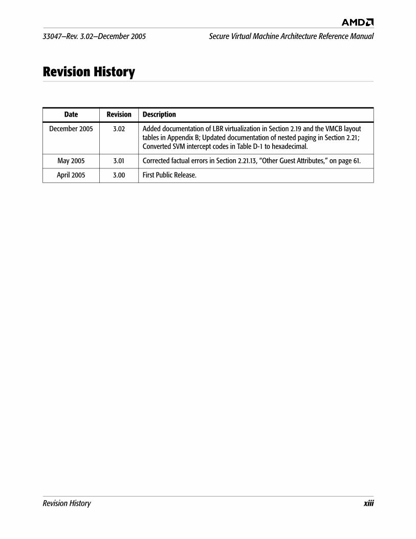
December 2005 3.02 Added documentation of LBR virtualization in Section 2.19 and the VMCB layout tables in Appendix B; Updated documentation of nested paging in Section 2.21; Converted SVM intercept codes in Table D-1 to hexadecimal.
May 2005 3.01 Corrected factual errors in Section 2.21.13, “Other Guest Attributes,” on page 61.
April 2005 3.00 First Public Release.
xiv Revision History
Secure Virtual Machine Architecture Reference Manual 33047—Rev. 3.02—December 2005
Preface xv
33047—Rev. 3.02—December 2005 Secure Virtual Machine Architecture Reference Manual
Preface
About This Book
This book describes the AMD64 technology Security andVirtual Machine (SVM) architecture, software requirements,instruction set extensions, changes to existing instructions, andnew bit settings in system registers.
Audience
This volume is intended for programmers writing virtualmachine monitor software and other SVM applications orsystem utilities. It assumes an understanding of AMD64architecture application-level and system-level programming asdescribed in Volumes 1 and 2 of the AMD64 ArchitectureProgrammer’s Manual (order# 24592 and order# 24593).
This volume describes SVM architecture resources andfunctions that are managed by system software, includingoperating-mode control, memory management, intercepts,interrupts and exceptions, state-change management, system-management mode, and processor initialization, as well asextensions to the AMD64 instruction set that are used tooperate on SVM data structures.
xvi Preface
Secure Virtual Machine Architecture Reference Manual 33047—Rev. 3.02—December 2005
Organization
This volume begins with an overview of SVM, followed bychapters that describe the following details of systemprogramming:
System Resources—The data structures, system registers,software responsibilities, and hardware support toimplement SVM systems.
SVM Instruction Set—The extensions to the AMD64instruction set used to control SVM operations.
The appendices describe details of model-specific registers(MSRs) and data strucure layout. Definitions assumedthroughout this volume are listed below. The index at the end ofthis volume cross-references topics within the volume. For othertopics relating to the AMD64 architecture, see the tables ofcontents and indices of the references given in “RelatedDocuments” on page xxv.
Definitions
Some of the following definitions assume a knowledge of thelegacy x86 architecture. See “Related Documents” on page xxvfor descriptions of the legacy x86 architecture.
Terms and Notation 1011bA binary value—in this example, a 4-bit value.
F0EAhA hexadecimal value—in this example a 2-byte value.
[1,2)A range that includes the left-most value (in this case, 1) butexcludes the right-most value (in this case, 2).
7:4A bit range, from bit 7 to 4, inclusive. The high-order bit isshown first.
32-bit modeLegacy mode or compatibility mode in which a 32-bitaddress size is active. See legacy mode and compatibilitymode.
Preface xvii
33047—Rev. 3.02—December 2005 Secure Virtual Machine Architecture Reference Manual
64-bit modeA submode of long mode. In 64-bit mode, the default addresssize is 64 bits and new features, such as register extensions,are supported for system and application software.
#GP(0)Notation indicating a general-protection exception (#GP)with error code of 0.
absoluteA displacement that references the base of a code segmentrather than an instruction pointer. Contrast with relative.
ASIDAddress space identifier.
byteEight bits.
clearTo write a bit value of 0. Compare set.
compatibility modeA submode of long mode. In compatibility mode, the defaultaddress size is 32 bits, and legacy 16-bit and 32-bitapplications run without modification.
CPLCurrent privilege level.
CR0–CR4A register range, from register CR0 through CR4, inclusive,with the low-order register first.
CR0.PE = 1Notation indicating that the PE bit of the CR0 register has avalue of 1.
displacementA signed value that is added to the base of a segment(absolute addressing) or an instruction pointer (relativeaddressing). Same as offset.
doublewordTwo words, or four bytes, or 32 bits.
xviii Preface
Secure Virtual Machine Architecture Reference Manual 33047—Rev. 3.02—December 2005
double quadwordEight words, or 16 bytes, or 128 bits. Also called octword.
DS:rSIThe contents of a memory location whose segment address isin the DS register and whose offset relative to that segmentis in the rSI register.
EFER.LME = 0Notation indicating that the LME bit of the EFER registerhas a value of 0.
effective address sizeThe address size for the current instruction after accountingfor the default address size and any address-size overrideprefix.
effective operand sizeThe operand size for the current instruction afteraccounting for the default operand size and any operand-size override prefix.
elementSee vector.
exceptionAn abnormal condition that occurs as the result of executingan instruction. The processor’s response to an exceptiondepends on the type of the exception. Control is transferredto the handler (or service routine) for that exception, asdefined by the exception’s vector. When unmasked, theexception handler is called, and when masked, a defaultresponse is provided instead of calling the handler.
FF /0Notation indicating that FF is the first byte of an opcode,and a subopcode in the ModR/M byte has a value of 0.
flushAn often ambiguous term meaning (1) writeback, ifmodified, and invalidate, as in “flush the cache line,” or (2)invalidate, as in “flush the pipeline,” or (3) change a value,as in “flush to zero.”
Preface xix
33047—Rev. 3.02—December 2005 Secure Virtual Machine Architecture Reference Manual
GIFGlobal interrupt flag.
GDTGlobal descriptor table.
IDTInterrupt descriptor table.
IGNIgnore. Field is ignored.
IVTThe real-address mode interrupt-vector table.
LDTLocal descriptor table.
long modeAn operating mode unique to the AMD64 architecture. Aprocessor implementation of the AMD64 architecture canrun in either long mode or legacy mode. Long mode has twosubmodes, 64-bit mode and compatibility mode.
lsbLeast-significant bit.
LSBLeast-significant byte.
main memoryPhysical memory, such as RAM and ROM (but not cachememory) that is installed in a particular computer system.
maskA field of bits used for a control purpose.
MBZMust be zero. If software attempts to set an MBZ bit to 1, ageneral-protection exception (#GP) occurs.
memoryUnless otherwise specified, main memory.
msbMost-significant bit.
xx Preface
Secure Virtual Machine Architecture Reference Manual 33047—Rev. 3.02—December 2005
MSBMost-significant byte.
octwordSame as double quadword.
offsetSame as displacement.
PAEPhysical-address extensions.
physical memoryActual memory, consisting of main memory and cache.
probeA check for an address in a processor’s caches or internalbuffers. External probes originate outside the processor, andinternal probes originate within the processor.
protected modeA submode of legacy mode.
quadwordFour words, or eight bytes, or 64 bits.
RAZRead as zero (0), regardless of what is written.
real-address modeSee real mode.
real modeA short name for real-address mode, a submode of legacymode.
relativeA displacement (also called offset) from an instructionpointer rather than the base of a code segment. Contrastwith absolute.
reservedFields marked as reserved may be used at some future time.
Preface xxi
33047—Rev. 3.02—December 2005 Secure Virtual Machine Architecture Reference Manual
To preserve compatibility with future processors, reservedfields require special handling when read or written bysoftware.Reserved fields may be further qualified as MBZ, RAZ, SBZor IGN (see definitions).Software must not depend on the state of a reserved field,nor upon the ability of such fields to return to a previouslywritten state.If a reserved field is not marked with one of the previousqualifiers, software must not change the state of that field; itmust reload that field with the same values returned from aprior read.
REXAn instruction prefix that specifies a 64-bit operand size andprovides access to additional registers.
SBZShould be zero. It is the responsibility of software to set SBZbits to zero. The result of setting an SBZ bit to 1 may beunpredictable.
setTo write a bit value of 1. Compare clear.
sticky bitA bit that is set or cleared by hardware and that remains inthat state until explicitly changed by software.
TSSTask-state segment.
vectorAn index into an interrupt descriptor table (IDT), used toaccess exception handlers. Compare exception.
virtual-8086 modeA submode of legacy mode.
VMCBVirtual machine control block.
VMMVirtual machine monitor.
xxii Preface
Secure Virtual Machine Architecture Reference Manual 33047—Rev. 3.02—December 2005
wordTwo bytes, or 16 bits.
x86See legacy x86.
Registers In the following list of registers, the names are used to refereither to a given register or to the contents of that register:
AH–DHThe high 8-bit AH, BH, CH, and DH registers. CompareAL–DL.
AL–DLThe low 8-bit AL, BL, CL, and DL registers. Compare AH–DH.
AL–r15BThe low 8-bit AL, BL, CL, DL, SIL, DIL, BPL, SPL, andR8B–R15B registers, available in 64-bit mode.
BPBase pointer register.
CRnControl register number n.
CSCode segment register.
eAX–eSPThe 16-bit AX, BX, CX, DX, DI, SI, BP, and SP registers or the32-bit EAX, EBX, ECX, EDX, EDI, ESI, EBP, and ESPregisters. Compare rAX–rSP.
EBPExtended base pointer register.
EFERExtended features enable register.
eFLAGS16-bit or 32-bit flags register. Compare rFLAGS.
EFLAGS32-bit (extended) flags register.
Preface xxiii
33047—Rev. 3.02—December 2005 Secure Virtual Machine Architecture Reference Manual
eIP16-bit or 32-bit instruction-pointer register. Compare rIP.
EIP32-bit (extended) instruction-pointer register.
FLAGS16-bit flags register.
GDTRGlobal descriptor table register.
GPRsGeneral-purpose registers. For the 16-bit data size, these areAX, BX, CX, DX, DI, SI, BP, and SP. For the 32-bit data size,these are EAX, EBX, ECX, EDX, EDI, ESI, EBP, and ESP. Forthe 64-bit data size, these include RAX, RBX, RCX, RDX,RDI, RSI, RBP, RSP, and R8–R15.
IDTRInterrupt descriptor table register.
IP16-bit instruction-pointer register.
LDTRLocal descriptor table register.
MSRModel-specific register.
r8–r15The 8-bit R8B–R15B registers, or the 16-bit R8W–R15Wregisters, or the 32-bit R8D–R15D registers, or the 64-bitR8–R15 registers.
rAX–rSPThe 16-bit AX, BX, CX, DX, DI, SI, BP, and SP registers, orthe 32-bit EAX, EBX, ECX, EDX, EDI, ESI, EBP, and ESPregisters, or the 64-bit RAX, RBX, RCX, RDX, RDI, RSI,RBP, and RSP registers. Replace the placeholder r withnothing for 16-bit size, “E” for 32-bit size, or “R” for 64-bitsize.
xxiv Preface
Secure Virtual Machine Architecture Reference Manual 33047—Rev. 3.02—December 2005
RAX64-bit version of the EAX register.
RAZRead as zero (0), regardless of what is written.
RBP64-bit version of the EBP register.
RBX64-bit version of the EBX register.
RCX64-bit version of the ECX register.
RDI64-bit version of the EDI register.
RDX64-bit version of the EDX register.
rFLAGS16-bit, 32-bit, or 64-bit flags register. Compare RFLAGS.
RFLAGS64-bit flags register. Compare rFLAGS.
rIP16-bit, 32-bit, or 64-bit instruction-pointer register. CompareRIP.
RIP64-bit instruction-pointer register.
RSI64-bit version of the ESI register.
RSP64-bit version of the ESP register.
SPStack pointer register.
SSStack segment register.
Preface xxv
33047—Rev. 3.02—December 2005 Secure Virtual Machine Architecture Reference Manual
TPRTask priority register (CR8), a new register introduced inthe AMD64 architecture to speed interrupt management.
TRTask register.
Endian Order The x86 and AMD64 architectures address memory using little-endian byte-ordering. Multibyte values are stored with theirleast-significant byte at the lowest byte address, and they areillustrated with their least significant byte at the right side.Strings are illustrated in reverse order, because the addresses oftheir bytes increase from right to left.
Related DocumentsAMD64 Architecture Programmer’s Manual Volume 1:Application Programming, order# 24592.
AMD64 Architecture Programmer’s Manual Volume 2: SystemProgramming, order# 24593.
AMD64 Architecture Programmer’s Manual Volume 3: GeneralPurpose and System Instructions, order# 24594.
xxvi Preface
Secure Virtual Machine Architecture Reference Manual 33047—Rev. 3.02—December 2005
33047—Rev. 3.02—December 2005 Secure Virtual Machine Architecture Reference Manual
Chapter 1: Introduction 1
1 Introduction
AMD security and virtual machine (SVM) architecture isdesigned to provide enterprise-class server virtualizationsoftware technology that facilitates virtualization developmentand deployment. An SVM enabled virtual machine architectureshould provide hardware resources that allow a single machineto run multiple operating systems efficiently, while maintainingsecure, resource-guaranteed isolation.
1.1 The Virtual Machine Monitor
A virtual machine monitor (VMM, also known as a hypervisor)consists of software that controls the execution of multiple guestoperating systems on a single physical machine; the VMMprovides each guest the appearance of full control over acomplete computer system (memory, CPU, and all peripheraldevices). The use of the term host refers to the executioncontext of the VMM. World switch refers to the operation ofswitching between the host and guest.
Fundamentally, VMMs work by intercepting and emulating in asafe manner sensitive operations in the guest (such as changingthe page tables, which could give a guest access to memory it isnot allowed to access). AMD’s SVM provides hardware assists toimprove performance and facilitate implementation ofvirtualization.
1.2 SVM Hardware Overview
SVM processor support provides a set of hardware extensionsdesigned to enable economical and efficient implementation ofvirtual machine systems. Generally speaking, hardware supportfalls into two complementary categories: virtualization supportand security support.
1.2.1 Virtualization Support
The AMD virtual machine architecture is designed to provide:
Mechanisms for fast world switch between VMM and guest
The ability to intercept selected instructions or events in theguest
External (DMA) access protection for memory.
Secure Virtual Machine Architecture Reference Manual 33047—Rev. 3.02—December 2005
2 Chapter 1: Introduction
Assists for interrupt handling and virtual interrupt support
A guest/host tagged TLB to reduce virtualization overhead.
1.2.2 Guest Mode This new processor mode is entered through the VMRUNinstruction. When in guest mode, the behavior of some x86instructions changes to facilitate virtualization.
1.2.3 External Access Protection
Guests may be granted direct access to selected I/O devices.Hardware support is designed to prevent devices owned by oneguest from accessing memory owned by another guest (or theVMM).
1.2.4 Tagged TLB In the SVM usage model, the VMM is mapped in a differentaddress space than the guest. To reduce the cost of worldswitches, the TLB is tagged with an address space identifier(ASID) distinguishing host-space entries from guest-spaceentries.
1.2.5 Interrupt Support
To facilitate efficient virtualization of interrupts, the followingsupport is provided under control of VMCB flags:
Intercepting physical interrupt delivery. The VMM can request thatphysical interrupts cause a running guest to exit, allowing theVMM to process the interrupt.
Virtual interrupts. The VMM can inject virtual interrupts into theguest. Under control of the VMM, a virtual copy of theEFLAGS.IF interrupt mask bit, and a virtual copy of the APIC'stask priority register are used transparently by the guestinstead of the physical resources.
Sharing a physical APIC. SVM allows multiple guests to share aphysical APIC while guarding against malicious or defectiveguests that might leave high -pr ior i ty interruptsunacknowledged forever (and thus shut out other guest'sinterrupts).
1.2.6 Restartable Instructions
SVM is designed to safely restart, with the exception of taskswitches, any intercepted instruction after the intercept.Instructions are either atomic or idempotent.
1.2.7 Security Support To further enable secure initialization SVM provides additionalSystem support.
33047—Rev. 3.02—December 2005 Secure Virtual Machine Architecture Reference Manual
Chapter 1: Introduction 3
Attestation. The SKINIT instruction and associated systemsupport (the Trusted Platform Module, or TPM) allow forverifiable startup of trusted software (such as a VMM), basedon secure hash comparison.
Memory Clear. Automatic memory clear erases the contents ofsystem memory on reset to prevent simple reset-based attackson secrets stored in memory.
Secure Virtual Machine Architecture Reference Manual 33047—Rev. 3.02—December 2005
4 Chapter 1: Introduction
33047—Rev. 3.02—December 2005 Secure Virtual Machine Architecture Reference Manual
Chapter 2: SVM Processor and Platform Extensions 5
2 SVM Processor and Platform Extensions
This chapter describes the operation of the SVM hardwareextensions. These extensions can be grouped into the followingcategories:
State switch—VMRUN, VMSAVE, VMLOAD instructions,global interrupt flag (GIF), and instructions to manipulatethe latter (STGI, CLGI). (“VMRUN Instruction” on page 5,“VMSAVE and VMLOAD Instructions” on page 29, “GlobalInterrupt Flag, STGI and CLGI Instructions” on page 31)
Intercepts—allow the VMM to intercept sensitive operationsin the guest. (“Intercept Operation” on page 13 through“Miscellaneous Intercepts” on page 28)
Interrupt and APIC assists—physical interrupt intercepts,virtual interrupt support, APIC.TPR virtualization. (“GlobalInterrupt Flag, STGI and CLGI Instructions” on page 31 and“Interrupt and localAPIC Support” on page 35)
SMM intercepts and assists (“SMM Support” on page 40)
External (DMA) access protection (“External AccessProtection” on page 43)
Nested paging support for two levels of address translation.(“Nested Paging Facility” on page 52)
Security—SKINIT instruction, automatic memory clear.(“Secure Startup with SKINIT” on page 61)
2.1 Enabling SVM
Before any SVM instruction (VMRUN, VMLOAD, VMSAVE,VMMCALL, STGI, CLGI, SKINIT, INVLPGA) can be used,EFER.SVME (bit 12 of the EFER MSR register) must be setto 1. While EFER.SVME is zero (the default after reset), SVMinstructions cause #UD faults.
2.2 VMRUN Instruction
The VMRUN instruction is the cornerstone of SVM. VMRUNtakes, as a single argument, the physical address of a 4KB-aligned page, the virtual machine control block (VMCB), whichdescribes a virtual machine (guest) to be executed. The VMCBcontains:
Secure Virtual Machine Architecture Reference Manual 33047—Rev. 3.02—December 2005
6 Chapter 2: SVM Processor and Platform Extensions
a list of which instructions or events in the guest (e.g., writeto CR3) to intercept,
various control bits that specify the execution environmentof the guest or that indicate special actions to be takenbefore running guest code, and
guest processor state (such as control registers, etc.).
2.2.1 Basic Operation The VMRUN instruction has an implicit addressing mode of[rAX]. Software must load RAX (EAX in 32-bit mode) with thephysical address of the VMCB, a 4-Kbyte-aligned page thatdescribes a virtual machine to be executed. The portion of RAXused in forming the address is determined by the currenteffective address size.
The VMCB is accessed by physical address and should bemapped as writeback (WB) memory.
VMRUN is available only at CPL-0 (a #GP exception is raised ifthe CPL is greater than 0). Furthermore, the processor must bein protected mode and SVME.EFER must be set to 1(otherwise, a #UD exception is raised).
The VMRUN instruction saves some host processor stateinformation in the host state save area in main memory at thephysical address specified in the VM_HSAVE_AREA MSR; itthen loads corresponding guest state from the VMCB state-savearea. VMRUN also reads additional control bits from the VMCBthat allow the VMM to flush the guest TLB, inject virtualinterrupts into the guest, etc.
The VMRUN instruction then checks the guest state justloaded. If illegal state has been loaded, the processor exits backto the host (see “#VMEXIT” on page 12).
Otherwise, the processor now runs the guest code until anintercept event occurs, at which point the processor suspendsguest execution and resumes host execution at the instructionfollowing the VMRUN. This is called a #VMEXIT and isdescribed in detail in “#VMEXIT” on page 12.
VMRUN saves or restores a minimal amount of stateinformation to allow the VMM to resume execution after aguest has exited. This allows the VMM to handle simpleintercept conditions quickly. If additional guest stateinformation must be saved or restored (e.g., to handle morecomplex intercepts or to switch to a different guest), the VMM
33047—Rev. 3.02—December 2005 Secure Virtual Machine Architecture Reference Manual
Chapter 2: SVM Processor and Platform Extensions 7
can employ the VMSAVE and VMLOAD instructions (see“VMSAVE and VMLOAD Instructions” on page 29).
Saving Host State. To assure that the host can resume operationafter #VMEXIT, VMRUN saves at least the following host stateinformation at the physical address specified in the new MSR,VM_HSAVE_PA:
CS.SEL, NEXT_RIP—The CS selector and RIP of theinstruction following the VMRUN. On #VMEXIT the hostresumes running at this address.
RFLAGS, RAX—Host processor mode and the register usedby VMRUN to address the VMCB.
SS.SEL, RSP—Host’s stack pointer.
CR0, CR3, CR4, EFER—Host’s paging/operating mode.
IDTR, GDTR—The pseudo-descriptors. (VMRUN does notsave or restore the host LDTR.)
ES.SEL and DS.SEL.
Processor implementations may store only part (or none) ofhost state in the memory area pointed to by VM_HSAVE_AREAand may store some or all host state in hidden on-chip memory.Different implementations may choose to save the hidden partsof the host’s segment registers as well as the selectors. For thesereasons, software must not rely on the format or contents of thehost state save area, nor attempt to change host state bymodifying the contents of the host save area.
Loading Guest State. After saving host state, VMRUN loads thefollowing guest state from the VMCB:
CS, RIP—Guest begins execution at this address. Thehidden state of the CS segment register is also loaded fromthe VMCB.
RFLAGS, RAX.
SS, RSP—Includes the hidden state of the SS segmentregister.
CR0, CR2, CR3, CR4, EFER—Guest paging mode. Writingpaging-related control registers with VMRUN does not flushthe TLB (since address spaces are switched).
INTERRUPT_SHADOW—This flag indicates whether theguest is currently in an interrupt lockout shadow; see“Interrupt Shadows” on page 36.
Secure Virtual Machine Architecture Reference Manual 33047—Rev. 3.02—December 2005
8 Chapter 2: SVM Processor and Platform Extensions
IDTR, GDTR.
ES and DS—Includes the hidden state of the segmentregisters.
DR7 and DR6—The guest’s breakpoint state.
V_TPR—The guest’s virtual TPR.
V_IRQ—The flag indicating whether a virtual interrupt ispending in the guest.
CPL—If the guest is in real mode, the CPL is forced to 0; ifthe guest is in v86 mode, the CPL is forced to 3. Otherwise,the CPL saved in the VMCB is used.
The processor checks the loaded guest state for consistency. Ifan illegal mode is detected or an exception was encounteredwhile loading guest state, the processor performs a #VMEXITimmediately and stores VMEXIT_INVALID as an errorindication in the VMCB EXITCODE field.
If the guest is in PAE paging mode according to the registersjust loaded, the processor will also read the four PDPEs pointedto by the newly loaded CR3 value; setting any reserved bits inthe PDPEs also causes a #VMEXIT.
It is possible for the VMRUN instruction to load a guest RIPthat is outside the limit of the guest’s code segment or that isnon-canonical (if running in long mode). If this occurs, a #GPfault is delivered inside the guest; the RIP falling outside thelimit of the guest’s code segment is not considered illegal gueststate.
After all guest state is loaded, and intercepts and other controlbits are set up, the processor reenables interrupts by settingGIF to 1. (It is assumed that VMM software cleared GIF sometime before executing the VMRUN instruction, to ensure anatomic state switch).
Control Bits. Besides loading guest state, the VMRUN instructionreads various control fields from the VMCB; most of these fieldsare not written back to the VMCB on #VMEXIT (since theycannot change during guest execution):
TSC_OFFSET—an offset to add when the guest reads theTSC (time stamp counter). Guest writes to the TSC can beintercepted and emulated by changing the offset (withoutwriting the physical TSC). This offset is cleared when theguest exits back to the host.
33047—Rev. 3.02—December 2005 Secure Virtual Machine Architecture Reference Manual
Chapter 2: SVM Processor and Platform Extensions 9
V_INTR_PRIO, V_INTR_VECTOR, V_IGN_TPR—fieldsused to describe a virtual interrupt for the guest (see“Injecting Virtual (INTR) Interrupts” on page 36).
V_INTR_MASKING—controls whether masking ofinterrupts (in EFLAGS.IF and TPR) is to be virtualized (seeSection 2.17 on page 35).
The address space ID (ASID) to use while running the guest.(See Appendix B, “Processor Feature Identification,” onpage 91 for feature identification, including how manyASIDs are implemented.)
A field to control flushing of the TLB during a VMRUN (seeSection 2.12).
The intercept vector describing the active intercepts for theguest. On exit from the guest, the internal interceptregisters are cleared so no host operations will beintercepted.
Segment State in the VMCB. The segment registers are stored in theVMCB in a format similar to that for SMM: both base and limitare fully expanded; segment attributes are stored as 12-bitvalues formed by the concatenation of bits 55–52 and 47–40from the original 64-bit (in-memory) segment descriptors; thedescriptor “P” bit is used to signal NULL segments (P==0)where permissible and/or relevant. When loaded from theVMCB, only some of the attribute bits are observed byhardware, depending on the segment register in question:
CS—D, L, R (null code segment are not allowed).
SS—B, P, DPL, E, W (null stack segments allowed in 64-bitmode only).
DS, ES, FS, GS —D, P, DPL, E, W, Code/Data.
LDTR—Only the P bit is observed.
TR—Only TSS type (32 or 16 bit) is relevant, since a null TSSis not allowed.
The VMM should follow these rules when storing segmentattributes into the VMCB:
For NULL segments, set all attribute bits to zero.
Otherwise, write the concatenation of bits [55–52] and[47–40] from the original 64-bit (in-memory) segmentdescriptors.
Secure Virtual Machine Architecture Reference Manual 33047—Rev. 3.02—December 2005
10 Chapter 2: SVM Processor and Platform Extensions
The processor reads the current privilege level from the CPLfield in the VMCB, not from SS.DPL. However, SS.DPLshould match the CPL field.
When in virtual x86 or real mode, the processor ignores theCPL field in the VMCB (and forces the values of 3 and 0,respectively).
When examining segment attributes after a #VMEXIT:
Test the Present (P) bit to check whether a segment isNULL; note that CS and TR never contain NULL segmentsand so their P bit is meaningless;
Retrieve the CPL from the CPL field in the VMCB, not fromany segment DPL.
Canonicalization and Consistency Checks. The VMRUN instructionperforms consistency checks on host and guest state, very muchlike RSM performs checks on the new state. Illegal guest statecombinat ions cause a #VMEXIT with error code ofVMEXIT_INVALID. The following conditions are consideredillegal state combinations:
EFER.SVME is zero.
CR0.CD is zero and CR0.NW is set.
CR0[63–32] are not zero.
Any MBZ bits of CR3 are set.
CR4[63–11] are not zero.
DR6[63–32] are not zero.
DR7[63–32] are not zero.
EFER[63–15] are not zero.
EFER.LMA or EFER.LME is non-zero and this processordoes not support long mode.
EFER.LME and CR0.PG are both set and CR4.PAE is zero.
EFER.LME and CR0.PG are both non-zero and CR0.PE iszero.
EFER.LME, CR0.PG, CR4.PAE, CS.L, and CS.D are all non-zero.
The VMRUN or SMI intercept bits are clear.
The SMI intercept bit is zero.
(Other MBZ bits exist in various registers stored in theVMCB.)
33047—Rev. 3.02—December 2005 Secure Virtual Machine Architecture Reference Manual
Chapter 2: SVM Processor and Platform Extensions 11
The MSR or IOIO intercept tables extend to a physicaladdress ≥ the maximum supported physical address
Illegal event injection (see Section 2.16 on page 33).
VMRUN can load a guest value of CR0 with PE = 0 but PG = 1, acombination that is otherwise illegal (see Section 2.15).
In addition to consistency checks, VMRUN and #VMEXITcanonicalize (i.e., sign-extend to 63 bits) all base addresses inthe segment registers that have been loaded.
VMRUN and TF/RF bits in EFLAGS. When considering interactions ofVMRUN with the TF and RF bits in EFLAGS, one mustdistinguish between the behavior of host as opposed to that ofthe guest.
From the host point of view, VMRUN acts like a singleinstruction, even though an arbitrary number of guestinstructions may execute before a #VMEXIT effectivelycompletes the VMRUN. As a single host instruction, VMRUNinteracts with EFLAGS.RF and EFLAGS.TF like ordinaryinstructions. EFLAGS.RF suppresses any potential instructionbreakpoint match on the VMRUN, and EFLAGS.TF causes a#DB trap after the VMRUN completes on the host side (i.e.,after the #VMEXIT from the guest). As with any normalinstruction, completion of the VMRUN instruction clears thehost EFLAGS.RF bit.
The first guest instruction obeys the value of EFLAGS.RF fromthe VMCB. When VMRUN loads a guest value of 1 forEFLAGS.RF, that value takes effect and suppresses anypotential (guest) instruction breakpoint on the first guestinstruction. When VMRUN loads a guest value of 1 inEFLAGS.TF, that value does not cause a trace trap between theVMRUN and the first guest instruction, but rather aftercompletion of the first guest instruction.
Host values of EFLAGS have no effect on the guest and guestvalues of EFLAGS have no effect on the host.
See also Section 2.4.1 on page 14 regarding the value ofEFLAGS.RF saved on #VMEXIT.
Secure Virtual Machine Architecture Reference Manual 33047—Rev. 3.02—December 2005
12 Chapter 2: SVM Processor and Platform Extensions
2.3 #VMEXIT
When an intercept triggers, the processor performs a #VMEXIT(i.e., an exit from the guest to the host context).
On #VMEXIT, the processor:
Disables interrupts by clearing the GIF, so that after the#VMEXIT, VMM software can complete the state switchatomically.
Writes back to the VMCB the current guest state—the samesubset of processor state as is loaded by the VMRUNinstruction, including the V_IRQ, V_TPR, and theINTERRUPT_SHADOW bits.
Saves the reason for exiting the guest in the VMCB’sEXITCODE field; additional information may be saved inthe EXITINFO1 or EXITINFO2 fields, depending on theintercept.
Clears all intercepts.
Resets the current ASID register to zero (host ASID).
Clears the V_IRQ and V_INTR_MASKING bits inside theprocessor.
Clears the TSC_OFFSET inside the processor.
Reloads the host state previously saved by the VMRUNinstruction.
Note: The processor reloads the host’s CS, SS, DS, and ES segmentregisters and, if required, re-reads the descriptors from thehost’s segment descriptor tables, depending on theimplementation. Software should keep the host’s segmentdescriptor tables consistent with the segment registers whenexecuting VMRUN instructions. Immediately after#VMEXIT, the processor still contains the guest value forLDTR. So for CS, SS, DS, and ES, the VMM must only usesegment descriptors from the global descriptor table. Anyexception encountered while reloading the host segmentscauses a shutdown.
If the host is in PAE mode, the processor reloads the host'sPDPEs from the page table indicated by the host's CR3.. Ifthe PDPEs contain illegal state, the processor shuts down.
Forces CR0.PE = 1, RFLAGS.VM = 0.
Sets the host CPL to zero.
33047—Rev. 3.02—December 2005 Secure Virtual Machine Architecture Reference Manual
Chapter 2: SVM Processor and Platform Extensions 13
Disables all breakpoints in the host DR7 register.
Checks the reloaded host state for consistency; any errorcauses the processor to shutdown. If the host’s RIP reloadedby #VMEXIT is outside the limit of the host’s code segmentor non-canonical (in the case of long mode), a #GP fault isdelivered inside the host.
Note: When loading segment bases from the VMCB or the host-save area (on VMRUN or #VMEXIT), segment bases arecanonicalized (i.e., sign-extended from the highestimplemented address bit to bit 63); see the AMD64Architecture Programmer’s Manual, Volume 2: SystemProgramming, order# 24593.
Any illegal state or exception encountered while reloading hostsegment state in the VMCB state will cause a processorshutdown.
2.4 Intercept Operation
Various instructions and events (such as exceptions) in theguest can be intercepted by means of control bits in the VMCB.The two primary classes of intercepts supported by SVM areinstruction and exception intercepts.
Exception intercepts. Exception intercepts are checked whennormal instruction processing must raise an exception—beforeresolving possible double-fault conditions according to table 8-3in Volume 2 of the AMD64 Architecture Programmer’s Manual,order# 24593, and before attempting delivery of the exception(which includes pushing an exception frame, accessing the IDT,etc.).
For some exceptions, the processor still writes certainexception-specific registers even if the exception is intercepted.(See the descriptions in Section 2.8 on page 23 and followingfor details.) When an external or virtual interrupt isintercepted, the interrupt is left pending.
When an intercept occurs while the guest is in the process ofdelivering a non-intercepted interrupt or exception using theIDT, SVM provides additional information on #VMEXIT (SeeSection 2.4.2 on page 14).
Secure Virtual Machine Architecture Reference Manual 33047—Rev. 3.02—December 2005
14 Chapter 2: SVM Processor and Platform Extensions
Instruction intercepts. These occur at well -defined points ininstruction execution—before the results of the instruction arecommitted, but ordered in an intercept-specific priority relativeto the instruction’s exception checks. Generally, instructionintercepts are checked after simple exceptions (such as #GPwhen CPL is incorrect, or #UD) have been checked, but beforeexceptions related to memory accesses (such as page faults) andexceptions based on specific operand values. There are severalexceptions to this guideline, e.g., the RSM instruction.Instruction breakpoints for the current instruction and pendingdata breakpoint traps from the previous instruction aredesigned to be checked before instruction intercepts.
2.4.1 State Saved on Exit
When triggered, intercepts write an EXITCODE into the VMCBidentifying the cause of the intercept. The EXITINTINFO fieldsignals whether the intercept occurred while the guest wasattempting to deliver an interrupt or exception through theIDT; a VMM can use this information to transparently completethe delivery (see “Event Injection” on page 33). Someintercepts provide additional information in the EXITINFO1and EXITINFO2 fields in the VMCB; see the individualintercept descriptions for details.
The guest state saved in the VMCB is the processor state as ofthe moment the intercept triggers. In the x86 architecture,traps (as opposed to faults) are detected and delivered after theinstruction that triggered them has completed execution.Accordingly, a trap intercept takes place after the execution ofthe instruction that triggered the trap in the first place. Thesaved guest state thus includes the effects of executing thatinstruction.
Example: Assume a guest instruction triggers a data breakpoint(#DB) trap which is in turn intercepted. The VMCB records theguest state after execution of that instruction, so that the savedCS:RIP points at the following instruction, and the saved DR7includes the effects of hitting the data breakpoint.
Some exceptions write special registers even when they areintercepted; see the individual descriptions in “ExceptionIntercepts” on page 23 for details.
2.4.2 Intercepts During IDT Interrupt Delivery
It is possible for an intercept to occur while the guest isattempting to deliver an exception or interrupt through the IDTe.g., #PF because the VMM has paged out the guest’s exception
33047—Rev. 3.02—December 2005 Secure Virtual Machine Architecture Reference Manual
Chapter 2: SVM Processor and Platform Extensions 15
stack). In some cases, such an intercept can result in the loss ofinformation necessary for transparent resumption of the guest.In the case of an external interrupt, for example, the processorwill already have performed an interrupt acknowledge cyclewith the PIC or APIC to obtain the interrupt type and vector,and the interrupt is thus no longer pending.
To recover from such situations, all intercepts indicate (in theEXITINTINFO field in the VMCB) whether they occurredduring exception or interrupt delivery though the IDT. Thismechanism allows the VMM to complete the interceptedinterrupt delivery, even when it is no longer possible to recreatethe event in question.
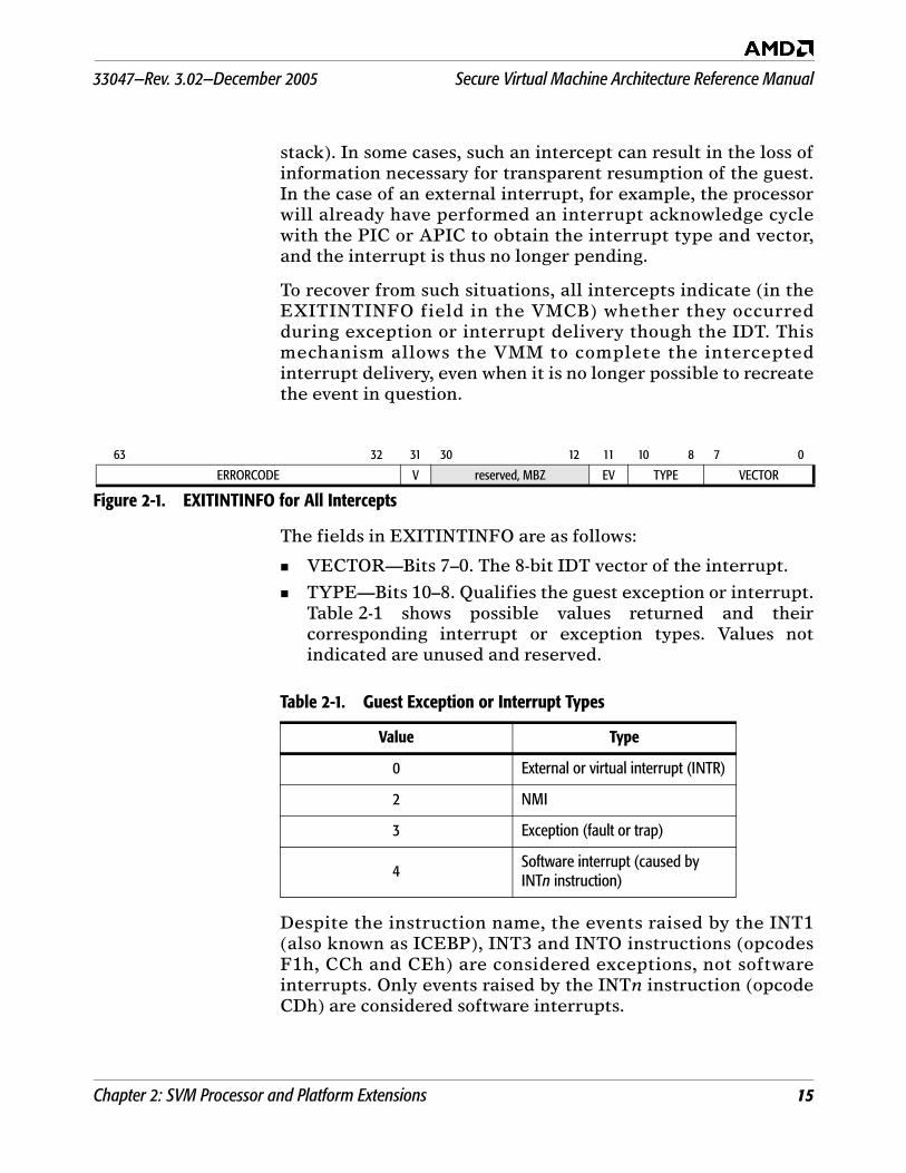
The fields in EXITINTINFO are as follows:
VECTOR—Bits 7–0. The 8-bit IDT vector of the interrupt.
TYPE—Bits 10–8. Qualifies the guest exception or interrupt.Table 2-1 shows possible values returned and theircorresponding interrupt or exception types. Values notindicated are unused and reserved.
Despite the instruction name, the events raised by the INT1(also known as ICEBP), INT3 and INTO instructions (opcodesF1h, CCh and CEh) are considered exceptions, not softwareinterrupts. Only events raised by the INTn instruction (opcodeCDh) are considered software interrupts.
63 32 31 30 12 11 10 8 7 0
ERRORCODE V reserved, MBZ EV TYPE VECTOR
Figure 2-1. EXITINTINFO for All Intercepts
Table 2-1. Guest Exception or Interrupt Types
Value Type
0 External or virtual interrupt (INTR)
2 NMI
3 Exception (fault or trap)
4 Software interrupt (caused by INTn instruction)
Secure Virtual Machine Architecture Reference Manual 33047—Rev. 3.02—December 2005
16 Chapter 2: SVM Processor and Platform Extensions
EV (error code valid)—Bit 11. Set to 1 if the guest exceptionwould have pushed an error code; cleared to zero otherwise.
V (valid)—Bit 31. Set to 1 if the intercept occurred while theguest attempted to deliver an exception through the IDT;otherwise cleared to zero.
ERRORCODE—Bits 63–32. If EV is set to 1, holds the errorcode that the guest exception would have pushed; otherwiseis undefined.
In the case of multiple exceptions, EXITINTINFO records theaggregate information on all exceptions but the last (andintercepted) one.
Example: A guest raises a #GP during delivery of which a #NP israised (a scenario that, according to x86 rules, resolves to a#DF), and an intercepted #PF occurs during the attempt todeliver the #DF. Upon intercept of the #PF, EXITINTINFOindicates that the guest was in the process of delivering a #DFwhen the #PF occurred. The information about the interceptedpage fault itself is encoded in the EXITCODE, EXITINFO1 andEXITINFO2 fields. If the VMM decides to repair and dismissthe #PF, it can resume guest execution by re-injecting (see“Event Injection” on page 33) the fault recorded inEXITINTINFO. If the VMM decides that the #PF should bereflected back to the guest, it must combine the event inEXITINTINFO with the intercepted exception according to x86rules (see table 8-3 in Volume 2 of the AMD64 ArchitectureProgrammer’s Manual, order# 24593). In this case, a #DF plus a#PF would result in a triple fault or shutdown.
2.4.3 EXITINTINFO Pseudo-Code
When delivering exceptions or interrupts in a guest, theprocessor checks for exception intercepts and updates the valueof EXITINTINFO should an intercept occur during exceptiondelivery. The following pseudo-code outlines how the processordelivers an event (exception or interrupt) E.
if E is an exception and is intercepted: #VMEXIT(E)E = (result of combining E with any prior events)
if (result was #DF and #DF is intercepted) : #VMEXIT(#DF)if (result was shutdown and shutdown is intercepted): #VMEXIT(#shutdown)EXITINTINFO = E // Record the event the guest is delivering.
33047—Rev. 3.02—December 2005 Secure Virtual Machine Architecture Reference Manual
Chapter 2: SVM Processor and Platform Extensions 17
Attempt delivery of E through the IDTNote that this may cause secondary exceptions
Once an exception has been successfully taken in the guest:
EXITINTINFO.V = 0 // Delivery succeeded;no #VMEXIT.Dispatch to first instruction of handler
When an exception triggers an intercept, the EXITCODE (andoptionally EXITINFO1 and EXITINFO2) fields always reflectthe (raw) intercepted exception, while EXITINTINFO (ifmarked valid) indicates the prior exception the guest wasattempting to deliver when the intercept occurred.
2.5 Instruction Intercepts
This section specifies which instructions check a givenintercept and, where relevant, how the intercept is prioritizedrelative to exceptions.
2.5.1 Read/Write of CR0
Checked by—MOV TO/FROM CR0, LMSW, SMSW, CLTS.
Priority—Checks non-memory exceptions (CPL, illegal bitcombinations, etc.) before the intercept. For LMSW and SMSW,checks SVM intercepts before checking memory exceptions.
2.5.2 Read/Write of CR3 (excluding task switch)
Checked by—MOV TO/FROM CR3 (not checked by task switchoperations).
Priority—Checks non-memory exceptions first, then theintercept. If the intercept triggers on a write, the intercepthappens before the TLB is flushed. If PAE is enabled, theloading of the four PDPEs can cause a #GP; that exception ischecked after the intercept check, so the VMM handling a CR3intercept cannot rely on the PDPEs being legal; it must examinethem in software if necessary.
The reads and writes of CR3 that occur in VMRUN, #VMEXITor task switches are not subject to this intercept check.
2.5.3 Read/Write of other CRs
Checked by—MOV TO/FROM CRn.
Priority—All normal exception checks take precedence overthe SVM intercepts.
2.5.4 Read/Write of Debug Registers, DRn
Checked by—MOV TO/FROM DRn. (Not checked by implicitDR6/DR7 writes.)
Secure Virtual Machine Architecture Reference Manual 33047—Rev. 3.02—December 2005
18 Chapter 2: SVM Processor and Platform Extensions
Priority—All normal exception checks take precedence overthe SVM intercepts.
2.5.5 Selective CR0 Write Intercept
Checked by—MOV TO CR0, LMSW
Priority—Checks non-memory exceptions (CPL, illegal bitcombinations, etc.) before the intercept. For LMSW and SMSW,checks SVM intercepts before checking memory exceptions.
The selective write intercept on CR0 triggers only if a bit otherthan CR0.TS or CR0.MP is being changed by the write. Inparticular, this means that CLTS does not check this intercept.
When both selective and non-selective CR0-write intercepts areactive at the same time, the non-selective intercept takespriority. With respect to exceptions, the priority of thisintercept is the same as the generic CR0-write intercept.
The LMSW instruction treats the selective CR0-write interceptas a non-selective intercept (i.e., it intercepts regardless of thevalue being written).
2.5.6 Reading/Writing of IDTR, GDTR, LDTR, TR
Checked by—LIDT, SIDT, LGDT, SGDT, LLDT, SLDT, LTR, STRinstructions, respectively.
Priority—The SVM intercept is checked after #UD and #GPexception checks, but before any memory access is performed.
2.5.7 RDTSC Instruction Intercept
Checked by—RDTSC instruction
Priority—Checks all exceptions before the SVM intercept.
2.5.8 RDPMC Instruction Intercept
Checked by—RDPMC instruction
Priority—Checks all exceptions before the SVM intercept.
2.5.9 PUSHF Instruction Intercept
Checked by—PUSHF instruction.
Priority—The intercept takes priority over any exceptions.
2.5.10 POPF Instruction Intercept
Checked by—POPF instruction.
Priority—The intercept takes priority over any exceptions.
2.5.11 CPUID Instruction Intercept
Checked by—CPUID instruction.
Priority—No exceptions to check.
33047—Rev. 3.02—December 2005 Secure Virtual Machine Architecture Reference Manual
Chapter 2: SVM Processor and Platform Extensions 19
2.5.12 RSM Instruction Intercept
Checked by—RSM instruction.
Priority—The intercept takes priority over any exceptions.
2.5.13 IRET Instruction Intercept
Checked by—IRET instruction.
Priority—The intercept takes priority over any exceptions.
2.5.14 Software Interrupt Intercept
Checked by—INTn instruction.
Priority—The intercept occurs before any exceptions arechecked. The CS:RIP reported on #VMEXIT are those of theintercepted INTn instruction.
Though the INTn instruction may dispatch through IDT vectorsin the range of 0–31, those events cannot be intercepted bymeans of exception intercepts (“Exception Intercepts” onpage 23).
2.5.15 INVD Instruction Intercept
Checked by—INVD instruction.
Priority—Exceptions (#GP) are checked before the intercept.
2.5.16 PAUSE Instruction Intercept
Checked by—PAUSE instruction (opcode F3 90).
Priority—No exceptions to check.
2.5.17 HLT Instruction Intercept
Checked by—HLT instruction.
Priority—Checks all exceptions before checking for thisintercept.
2.5.18 INVLPG Instruction Intercept
Checked by—INVLPG instruction.
Priority—Checks all exceptions (#GP) before the intercept.
2.5.19 INVLPGA Instruction Intercept
Checked by—INVLPGA instruction.
Priority—Checks all exceptions (#GP) before the intercept.
2.5.20 VMRUN Instruction Intercept
Checked by—VMRUN instruction.
Priority—Checks exceptions (#GP) before the intercept.
Note: The VMRUN intercept must always be set in the VMCB.
2.5.21 VMLOAD Instruction Intercept
Checked by—VMLOAD instruction.
Priority—Checks exceptions (#GP) before the intercept.
Secure Virtual Machine Architecture Reference Manual 33047—Rev. 3.02—December 2005
20 Chapter 2: SVM Processor and Platform Extensions
2.5.22 VMSAVE Instruction Intercept
Checked by—VMSAVE instruction.
Priority—Checks exceptions (#GP) before the intercept.
2.5.23 VMMCALL Instruction Intercept
Checked by—VMMCALL instruction.
Priority—The intercept takes priority over exceptions.VMMCALL causes #UD in the guest if it is not intercepted.
2.5.24 STGI Instruction Intercept
Checked by—STGI instruction.
Priority—Checks exceptions (#GP) before the intercept.
2.5.25 CLGI Instruction Intercept
Checked by—CLGI instruction.
Priority—Checks exceptions (#GP) before the intercept.
2.5.26 SKINIT Instruction Intercept
Checked by—SKINIT instruction.
Priority—Checks exceptions (#GP) before the intercept.
2.5.27 RDTSCP Instruction Intercept
Checked by—RDTSCP instruction.
Priority—Checks all exceptions before the SVM intercept.
2.5.28 ICEBP Instruction Intercept
Checked by—ICEBP instruction (opcode F1h).
Note: Although the ICEBP instruction dispatches through IDTvector 1, that event is not interceptable by means of the#DB exception intercept.
2.5.29 WBINVD Instruction Intercept
Checked by—WBINVD instructions.
Priority—Checks exceptions (#GP) before the intercept.
2.6 IOIO Intercepts
The VMM can intercept IOIO instructions (IN, OUT, INS,OUTS) on a port-by-port basis by means of the SVM I/Opermissions map.
I/O Permissions Map. The I/O Permissions Map (IOPM) occupies12 Kbytes of contiguous physical memory. The table isstructured as a linear array of 64K+3 bits (two 4-Kbyte pages,and the first three bits of a third 4-Kbyte page) and must bealigned on a 4-Kbyte boundary; the physical base address of theIOPM is specified in the IOPM_BASE_PA field in the VMCBand loaded into the processor by the VMRUN instruction.
33047—Rev. 3.02—December 2005 Secure Virtual Machine Architecture Reference Manual
Chapter 2: SVM Processor and Platform Extensions 21
Note: The VMRUN instruction ignores the lower 12 bits of theaddress specified in the VMCB. If the address of the last bytein the table is greater than or equal to the maximumsupported physical address, this is treated as illegal VMCBstate and causes a #VMEXIT(VMEXIT_INVALID).
Each bit in the table corresponds to an 8-bit I/O port. Bit 0 in thetable corresponds to I/O port 0, bit 1 to I/O port 1 and so on. Abit set to 1 indicates that accesses to the corresponding portshould be intercepted. The IOPM is accessed by physicaladdress, and should reside in memory that is mapped aswriteback (WB).
IN and OUT Behavior. If the IOIO_PROT intercept bit is set, theIOPM table controls port access. For IN/OUT instructions thataccess more than a single byte, the permission bits for all bytesare checked; if any bit is set to 1, the I/O operation isintercepted.
Exceptions related to virtual x86 mode, IOPL, or the TSS-bitmap are checked before the SVM intercept check. All otherexceptions are checked after the SVM intercept check.
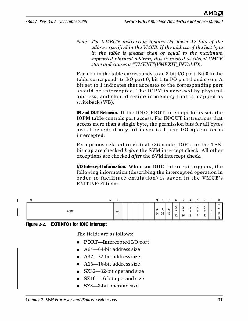
I/O Intercept Information. When an IOIO intercept triggers, thefollowing information (describing the intercepted operation inorder to facilitate emulation) is saved in the VMCB’sEXITINFO1 field:
The fields are as follows:
PORT—Intercepted I/O port
A64—64-bit address size
A32—32-bit address size
A16—16-bit address size
SZ32—32-bit operand size
SZ16—16-bit operand size
SZ8—8-bit operand size
31 16 15 9 8 7 6 5 4 3 2 1 0
PORT resA64
A32
A16
SZ
32
SZ16
SZ8
REP
STR
1
TYPE
Figure 2-2. EXITINFO1 for IOIO Intercept
Secure Virtual Machine Architecture Reference Manual 33047—Rev. 3.02—December 2005
22 Chapter 2: SVM Processor and Platform Extensions
REP—Repeated port access
STR—String based port access (INS, OUTS)
TYPE—Access type (0 = OUT instruction, 1 = IN instruction)
The RIP of the instruction following the IN/OUT is saved inEXITINFO2, so that the VMM can easily resume the guest afterI/O emulation.
2.7 MSR Intercepts
The VMM can intercept RDMSR and WRMSR instructions bymeans of the SVM MSR permissions map (MSRPM) on a per-MSR basis.
MSR Permissions Map. The MSR permissions bitmap consists of anumber of smaller separate bitmaps of 2K bytes each covering adefined range of 8K MSRs. Four of these smaller bitmaps residein two physical pages (8KB, covering 32K MSRs). One 8Kbyterange is used for the Pentium® compatible MSRs, the next 8Krange is used for the AMD sixth generation x86 processor(AMD-K6®) MSRs, and the third 8K range for the AMD seventhand eighth generation x86 processors (e.g., the AMD Athlon™and AMD Opteron™) MSRs. If the MSR_PROT intercept isactive, any attempt to read or write an MSR not covered by thebitmap will automatically cause an intercept.
The MSRPM is accessed by physical address, and should residein memory that is mapped as writeback (WB). The MSRPMmust be aligned on a 4KB boundary. The physical base addressof the MSRPM is specified in MSRPM_BASE_PA field in theVMCB and loaded into the processor by the VMRUNinstruction.
Note: The VMRUN instruction ignores the lower 12 bits of theaddress specified in the VMCB, and if the address of the lastbyte in the table is greater than or equal to the maximumsupported physical address, this is treated as illegal VMCBstate and causes a #VMEXIT(VMEXIT_INVALID).
33047—Rev. 3.02—December 2005 Secure Virtual Machine Architecture Reference Manual
Chapter 2: SVM Processor and Platform Extensions 23
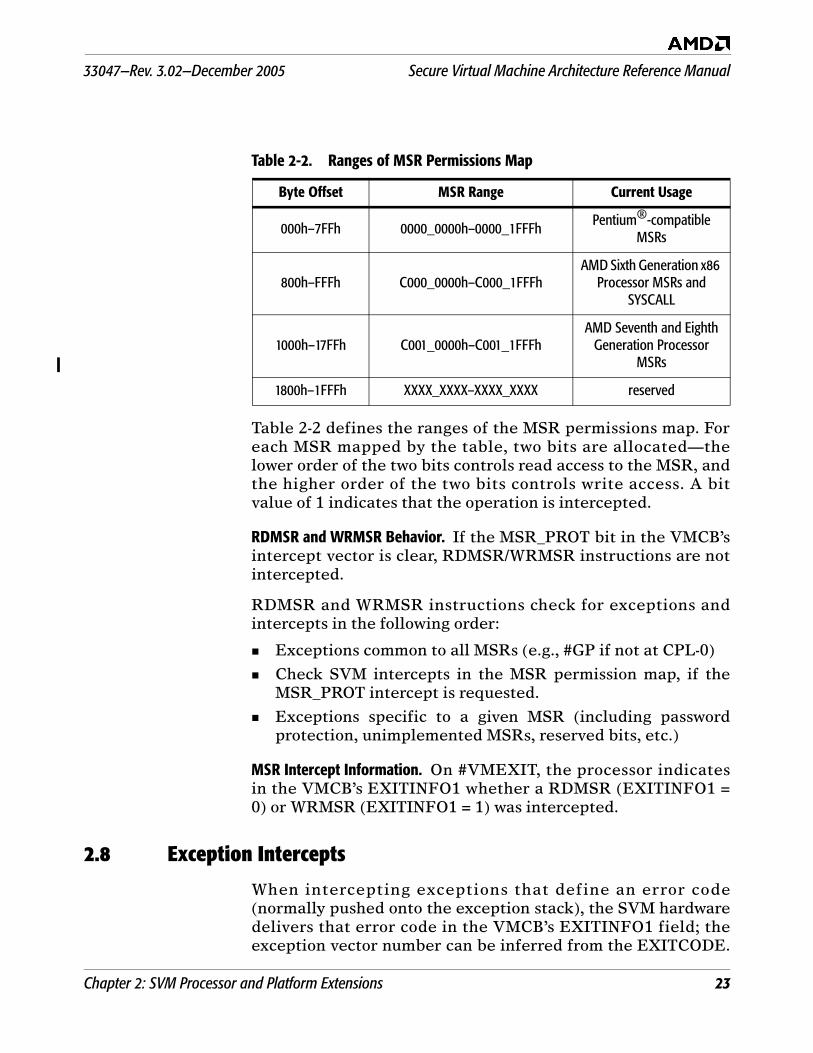
Table 2-2 defines the ranges of the MSR permissions map. Foreach MSR mapped by the table, two bits are allocated—thelower order of the two bits controls read access to the MSR, andthe higher order of the two bits controls write access. A bitvalue of 1 indicates that the operation is intercepted.
RDMSR and WRMSR Behavior. If the MSR_PROT bit in the VMCB’sintercept vector is clear, RDMSR/WRMSR instructions are notintercepted.
RDMSR and WRMSR instructions check for exceptions andintercepts in the following order:
Exceptions common to all MSRs (e.g., #GP if not at CPL-0)
Check SVM intercepts in the MSR permission map, if theMSR_PROT intercept is requested.
Exceptions specific to a given MSR (including passwordprotection, unimplemented MSRs, reserved bits, etc.)
MSR Intercept Information. On #VMEXIT, the processor indicatesin the VMCB’s EXITINFO1 whether a RDMSR (EXITINFO1 =0) or WRMSR (EXITINFO1 = 1) was intercepted.
2.8 Exception Intercepts
When intercepting exceptions that define an error code(normally pushed onto the exception stack), the SVM hardwaredelivers that error code in the VMCB’s EXITINFO1 field; theexception vector number can be inferred from the EXITCODE.
Table 2-2. Ranges of MSR Permissions Map
Byte Offset MSR Range Current Usage
000h–7FFh 0000_0000h–0000_1FFFh Pentium®-compatible MSRs
800h–FFFh C000_0000h–C000_1FFFhAMD Sixth Generation x86
Processor MSRs and SYSCALL
1000h–17FFh C001_0000h–C001_1FFFhAMD Seventh and Eighth
Generation Processor MSRs
1800h–1FFFh XXXX_XXXX–XXXX_XXXX reserved
Secure Virtual Machine Architecture Reference Manual 33047—Rev. 3.02—December 2005
24 Chapter 2: SVM Processor and Platform Extensions
The CS.SEL and RIP saved in the VMCB on an exception-intercept always match those that would otherwise have beenpushed onto the exception stack frame. Unless otherwise notedbelow, no special registers are written before an exception isintercepted. For details on guest state saved in the VMCB, seeSection 2.4.1.
External interrupts and software interrupts (INTn instruction)do not check the exception intercepts, even when they use avector in the range 0 to 31.
Exceptions that occur during the handling of a prior exceptionare checked for intercepts before being combined with the priorexception (e.g., into a double-fault). If the result of combiningexceptions is a double-fault or shutdown, the processor checkswhether those are intercepted before attempting delivery.
Example: Assume that the VMM intercepts #GP and #DFexceptions, and the guest raises a (non-intercepted) #NP, duringthe delivery of which it also gets a #GP (e.g., due to an illegalIDT entry)—a situation that, according to x86 semantics, resultsin a #DF. In this case, #VMEXIT signals an intercepted #GP, notan intercepted #DF and fills EXITINTINFO with the #NP fault.On the other hand, if only the #DF intercept were active in thisscenario, #VMEXIT would signal an intercepted #DF.
The following subsections detail the individual intercepts.
2.8.1 #DE (Divide By Zero)
The EXITINFO1 and EXITINFO2 fields are undefined.
2.8.2 #DB (Debug) The #DB exception can have fault-type (e.g., instructionbreakpoint) or trap-type (e.g., data breakpoint) behavior;accordingly the intercept differs in what state is saved in theVMCB (see “State Saved on Exit” on page 14). In either case,however, the value saved for DR6 and DR7 matches what wouldbe visible to a #DB exception handler (i.e., both #DB faults andtraps are permitted to write DR6 and DR7 before theintercept). The EXITINFO1 and EXITINFO2 fields areundefined.
Note: A vector 1 exception generated by the single byte INT1instruction (also known as ICEBP) does not trigger the #DBintercept. Software should use the dedicated ICEBPintercept to intercept ICEBP (see “ICEBP InstructionIntercept” on page 20).
33047—Rev. 3.02—December 2005 Secure Virtual Machine Architecture Reference Manual
Chapter 2: SVM Processor and Platform Extensions 25
2.8.3 Vector 2 (Reserved)
This intercept bit is not implemented; use the NMI intercept(Section 2.9.2) instead. The effect of setting this bit isundefined.
2.8.4 #BP (Breakpoint)
This intercept applies to the trap raised by the single byte INT3(opcode CCh) instruction. The EXITINFO1 and EXITINFO2fields are undefined.
2.8.5 #OF (Overflow) This intercept applies to the trap raised by the INTO (opcodeCEh) instruction. The EXITINFO1 and EXITINFO2 fields areundefined.
2.8.6 #BR (Bound-Range)
This intercept applies to the fault raised by the BOUNDinstruction. The EXITINFO1 and EXITINFO2 fields areundefined.
2.8.7 #UD (Invalid Opcode)
The EXITINFO1 and EXITINFO2 fields are undefined.
2.8.8 #NM (Device-Not-Available)
The EXITINFO1 and EXITINFO2 fields are undefined.
2.8.9 #DF (Double Fault)
The EXITINFO1 and EXITINFO2 fields are undefined. The RIPvalue saved in the VMCB is undefined (as is the case for the RIPvalue pushed on the stack for #DF exceptions).
Note: If a double fault is intercepted, the exceptions leading up tothe double fault will have written any status registersnormally written by those exceptions.
2.8.10 Vector 9 (Reserved)
This intercept is not implemented. The effect of setting this bitis undefined.
2.8.11 #TS (Invalid TSS)
The EXITINFO1 and EXITINFO2 fields are undefined. The RIPvalue saved in the VMCB may point to either the instructioncausing the task switch, or to the first instruction of theincoming task.
2.8.12 #NP (Segment Not Present)
The EXITINFO1 field contains the error code that would bepushed on the stack by a #NP exception. The EXITINFO2 fieldis undefined.
2.8.13 #SS (Stack Fault)
The EXITINFO1 field contains the error code that would bepushed on the stack by a #SS exception. The EXITINFO2 fieldis undefined.
Secure Virtual Machine Architecture Reference Manual 33047—Rev. 3.02—December 2005
26 Chapter 2: SVM Processor and Platform Extensions
2.8.14 #GP (General Protection)
The EXITINFO1 field contains the error code that would bepushed on the stack by a #GP exception.
2.8.15 #PF (Page Fault)
This intercept is tested before CR2 is written by the exception.The error code saved in EXITINFO1 is the same as would bepushed onto the stack by a non-intercepted #PF exception inprotected mode. The faulting address is saved in theEXITINFO2 field in the VMCB.
Note: Even when the guest is running in paged real mode, theprocessor will deliver the (protected-mode) page-fault errorcode in EXITINFO1, for the VMM to use in analyzing theintercepted #PF.
2.8.16 #MF (X87 Floating Point)
This intercept is tested after the floating point status word hasbeen written, as is the case for a normal FP exception. TheEXITINFO1 and EXITINFO2 fields are undefined.
2.8.17 #AC (Alignment Check)
The EXITINFO1 field contains the error code that would bepushed on the stack by an #AC exception. The EXITINFO2 fieldis undefined.
2.8.18 #MC (Machine Check)
The SVM intercept is checked after all #MC-specific registershave been written, but before other guest state is modified.When #MC is being intercepted, a machine-check exits to theVMM wherever possible, and shuts down the processor onlywhere this is not a reasonable option. The EXITINFO1 andEXITINFO2 fields are undefined.
2.8.19 #XF (SIMD Floating Point)
This intercept is tested after the SIMD status word (MXCSR)has been written, as is the case for a normal FP exception. TheEXITINFO1 and EXITINFO2 fields are undefined.
2.9 Interrupt Intercepts
External interrupts, when intercepted, cause a #VMEXIT; theinterrupt is held pending so that the interrupt can eventuallybe taken in the VMM. Exception intercepts do not apply toexternal or software interrupts, so it is not possible to interceptan interrupt by means of the exception intercepts, even if theinterrupt should happen to use a vector in the range from 0 to31.
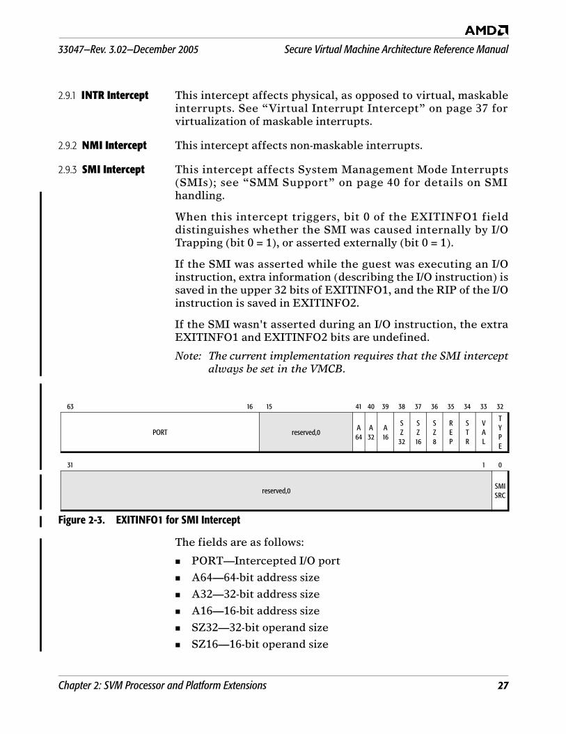
33047—Rev. 3.02—December 2005 Secure Virtual Machine Architecture Reference Manual
Chapter 2: SVM Processor and Platform Extensions 27
2.9.1 INTR Intercept This intercept affects physical, as opposed to virtual, maskableinterrupts. See “Virtual Interrupt Intercept” on page 37 forvirtualization of maskable interrupts.
2.9.2 NMI Intercept This intercept affects non-maskable interrupts.
2.9.3 SMI Intercept This intercept affects System Management Mode Interrupts(SMIs); see “SMM Support” on page 40 for details on SMIhandling.
When this intercept triggers, bit 0 of the EXITINFO1 fielddistinguishes whether the SMI was caused internally by I/OTrapping (bit 0 = 1), or asserted externally (bit 0 = 1).
If the SMI was asserted while the guest was executing an I/Oinstruction, extra information (describing the I/O instruction) issaved in the upper 32 bits of EXITINFO1, and the RIP of the I/Oinstruction is saved in EXITINFO2.
If the SMI wasn't asserted during an I/O instruction, the extraEXITINFO1 and EXITINFO2 bits are undefined.
Note: The current implementation requires that the SMI interceptalways be set in the VMCB.
The fields are as follows:
PORT—Intercepted I/O port
A64—64-bit address size
A32—32-bit address size
A16—16-bit address size
SZ32—32-bit operand size
SZ16—16-bit operand size
63 16 15 41 40 39 38 37 36 35 34 33 32
PORT reserved,0A64
A32
A16
SZ
32
SZ16
SZ8
REP
STR
VAL
TYPE
31 1 0
reserved,0SMISRC
Figure 2-3. EXITINFO1 for SMI Intercept
Secure Virtual Machine Architecture Reference Manual 33047—Rev. 3.02—December 2005
28 Chapter 2: SVM Processor and Platform Extensions
SZ8—8-bit operand size
REP—Repeated port access
STR—String based port access (INS, OUTS)
VAL—Valid
TYPE—Access type (0 = OUT instruction, 1 = INinstruction).
SMISRC—SMI source (0 = internal, 1 = external).
2.9.4 INIT Intercept This allows the VMM to intercept the assertion of INIT while aguest is running; see “INIT Support” on page 39 for a discussionof the INIT-redirection feature.
2.9.5 Virtual Interrupt Intercept
This intercept is taken just before a guest takes a virtualinterrupt. When the intercept triggers, the virtual interrupt hasnot been taken, and remains pending in the guest's VMCBV_IRQ field.
Note: This intercept is not required for handling fixed localAPICinterrupts, but may be used for emulating ExtINT interruptdelivery mode (which does not obey the TPR), or legacy PICsin auto-EOI mode.
2.10 Miscellaneous Intercepts
The SVM architecture includes intercepts to handle taskswitches, processor freezes due to FERR, and shutdownoperations.
2.10.1 Task Switch Intercept
Checked by—Any instruction or event that causes a task switch(e.g., JMP, CALL, exceptions, interrupts, software interrupts).
Priority—The intercept is checked before the task switch takesplace but after the incoming TSS and task gate (if one had beeninvolved) have been checked for correctness.
Task switches can modify several resources that a VMM mayneed to protect (CR3, EFLAGS, LDT). However, instead ofchecking various intercepts (e.g., CR3 Write, LDTR Write)individually, task switches check only this intercept bit.
On #VMEXIT, the following information is delivered in theVMCB:
EXITINFO1[15–0] holds the segment selector identifyingthe incoming TSS.
33047—Rev. 3.02—December 2005 Secure Virtual Machine Architecture Reference Manual
Chapter 2: SVM Processor and Platform Extensions 29
EXITINFO2[31–0] holds the error code to push in the newtask (undefined if not applicable).
EXITINFO2[63–32] holds auxiliary information:
- EXITINFO2[36]—Set to 1 if the task switch was causedby an IRET; else cleared to 0.
- EXITINFO2[38]—Set to 1 if the task switch was causedby a far jump; else cleared to 0.
- EXITINFO2[44]—Set to 1 if the task switch has anerrorcode; else cleared to 0.
- EXITINFO2[48]—The value of EFLAGS.RF that wouldbe saved in the outgoing TSS if the task switch were notintercepted.
2.10.2 Ferr_Freeze Intercept
Checked when the processor freezes due to assertion of FERR(while IGNNE is deasserted, and legacy handling of FERR isselected in CR0.NE), i.e., while the processor is waiting to beunfrozen by an external interrupt.
2.10.3 Shutdown Intercept
When this intercept occurs, any condition that normally causesa shutdown causes a #VMEXIT to the VMM instead.
Note: After an intercepted shutdown, the state saved in the VMCBis undefined.
2.11 VMSAVE and VMLOAD Instructions
The VMSAVE and VMLOAD instructions take the physicaladdress of a VMCB in the (implicit) rAX operand. Theinstructions are intended to complement the state save/restoreabilities of the VMRUN instruction. They provide access tohidden processor state that software cannot otherwise access,as well as additional privileged state.
VMSAVE saves the following state to the VMCB indicated byrAX:
FS, GS, TR, LDTR (including all hidden state)
KernelGsBase
STAR, LSTAR, CSTAR, SFMASK
SYSENTER_CS, SYSENTER_ESP, SYSENTER_EIP
VMLOAD loads the corresponding state from the VMCB.VMLOAD and VMSAVE are available only at CPL-0 (#GP
Secure Virtual Machine Architecture Reference Manual 33047—Rev. 3.02—December 2005
30 Chapter 2: SVM Processor and Platform Extensions
otherwise), and in protected mode with SVM enabled inEFER.SVME (#UD otherwise).
2.12 TLB Control
TLB entries are tagged with Address Space Identifier (ASID) bitsto distinguish different host and/or guest address spaces. TheVMM can choose a software strategy in which it keeps multipleshadow page tables (SPTs) and/or multiple host page tables (inprocessors that support nested paging) up-to-date; the VMMcan allocate a different ASID for each SPT or host page table.This allows switching to a new process in a guest (i.e., a newCR3 value, which means a new SPT) without flushing the TLBs.
For each guest address space, the VMM is responsible forsetting up a shadow page table or host page table that mapsguest virtual addresses to host physical addresses. In shadowpaging, the VMM should set the CR3 field in the guest VMCB topoint to the host physical address of this shadow page table.The VMM is responsible for updating the shadow page tablewhen the guest changes the page table or paging control state,and the VMM should update the access and dirty bits of theguest page table.
The VMRUN instruction and #VMEXIT write the CR0, CR3,CR4 and EFER registers — these writes do not flush the TLB.The VMM is responsible for explicitly invalidating any guesttranslations that may be affected by its actions; there are twomechanisms available, as described in the next two sections.
When running with SVM enabled, global page table entries(PTEs) are global only within an ASID, not across ASIDs.
Software Rule. When the VMM changes a guest’s paging mode bychanging entries in the guest’s VMCB, the VMM must ensurethat the guest’s TLB entries are flushed from the TLB. Therelevant VMCB state includes:
CR0—PG, WP, CD, NW.
CR3—Any bit.
CR4—PGE, PAE, PSE.
EFER—NXE, LMA, LME.
2.12.1 TLB Flush TLB flush operations function identically whether or not SVMis enabled (e.g., MOV-TO-CR3 flushes non-global mappings,
33047—Rev. 3.02—December 2005 Secure Virtual Machine Architecture Reference Manual
Chapter 2: SVM Processor and Platform Extensions 31
whereas MOV-TO-CR4 flushes global and non-global mappings),and affect all ASIDs. However, if a VMM sets the intercept bitfor any guest action that would have flushed the TLB, the#VMEXIT intercept occurs and the TLB is not flushed; it is theVMM's responsibility to flush the TLB appropriately. Inimplementations that do not provide a way to selectively flushall translations of a single specified ASID, software mayeffectively flush the guest's TLB entries by allocating a newASID for the guest and not reusing the old ASID until the entireTLB has been flushed at least once.
The TLB_CONTROL field in the VMCB currently has onecommand implemented. When the VMM sets theTLB_CONTROL field to 1, the VMRUN instruction flushes theTLB for all ASIDs, for both global and non-global pages. TheVMRUN instruction reads, but does not change, the value of theTLB_CONTROL field.
2.12.2 Invalidate Page, Alternate ASID
A new instruction, INVLPGA, allows the VMM to selectivelyinvalidate the TLB mapping for a given virtual page and a givenASID. The virtual address is specified in the implicit registeroperand rAX; the ASID is specified in ECX.
2.13 Global Interrupt Flag, STGI and CLGI Instructions
The global interrupt flag (GIF) is a bit that controls whetherinterrupts and other events can be taken by the processor. TheSTGI and CLGI instructions set and clear, respectively, the GIF.Table 2-3 shows how the value of the GIF affects how interruptsand exceptions are handled.
Table 2-3. Effect of the GIF on Interrupt Handling
Interrupt source GIF==0 GIF ==1
Debug exception or trap, due to breakpoint register match
Ignored and discarded Normal operation
Debug trace trap due to EFLAGS.TF
Normal operation Normal operation
RESET# Normal operation Normal operation
INIT Held pending until GIF==1 Normal operation, see Table 2-5 on page 39
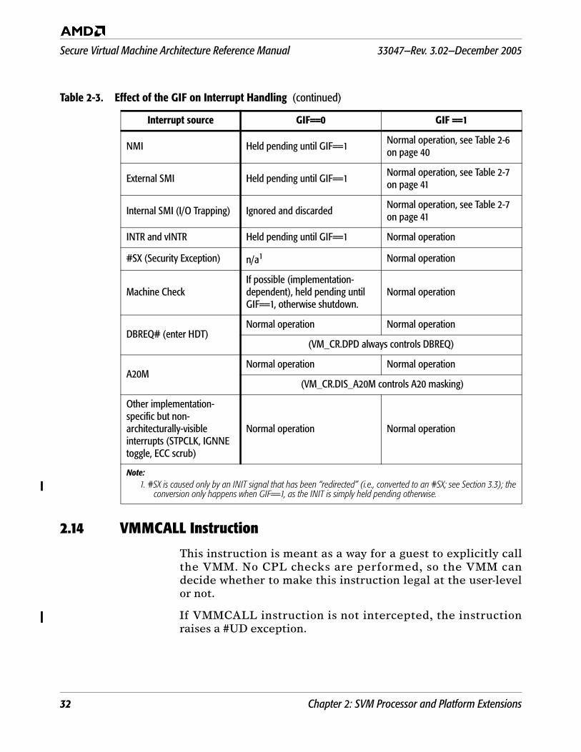
Secure Virtual Machine Architecture Reference Manual 33047—Rev. 3.02—December 2005
32 Chapter 2: SVM Processor and Platform Extensions
2.14 VMMCALL Instruction
This instruction is meant as a way for a guest to explicitly callthe VMM. No CPL checks are performed, so the VMM candecide whether to make this instruction legal at the user-levelor not.
If VMMCALL instruction is not intercepted, the instructionraises a #UD exception.
NMI Held pending until GIF==1 Normal operation, see Table 2-6 on page 40
External SMI Held pending until GIF==1 Normal operation, see Table 2-7 on page 41
Internal SMI (I/O Trapping) Ignored and discardedNormal operation, see Table 2-7 on page 41
INTR and vINTR Held pending until GIF==1 Normal operation
#SX (Security Exception) n/a1 Normal operation
Machine CheckIf possible (implementation-dependent), held pending until GIF==1, otherwise shutdown.
Normal operation
DBREQ# (enter HDT)Normal operation Normal operation
(VM_CR.DPD always controls DBREQ)
A20MNormal operation Normal operation
(VM_CR.DIS_A20M controls A20 masking)
Other implementation-specific but non-architecturally-visible interrupts (STPCLK, IGNNE toggle, ECC scrub)
Normal operation Normal operation
Note:1. #SX is caused only by an INIT signal that has been “redirected” (i.e., converted to an #SX; see Section 3.3); the
conversion only happens when GIF==1, as the INIT is simply held pending otherwise.
Table 2-3. Effect of the GIF on Interrupt Handling (continued)
Interrupt source GIF==0 GIF ==1
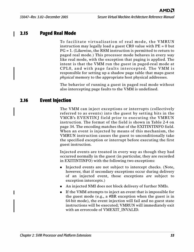
33047—Rev. 3.02—December 2005 Secure Virtual Machine Architecture Reference Manual
Chapter 2: SVM Processor and Platform Extensions 33
2.15 Paged Real Mode
To facilitate virtualization of real mode, the VMRUNinstruction may legally load a guest CR0 value with PE = 0 butPG = 1. (Likewise, the RSM instruction is permitted to return topaged real mode.) This processor mode behaves in every waylike real mode, with the exception that paging is applied. Theintent is that the VMM run the guest in paged-real mode atCPL0, and with page faults intercepted. The VMM isresponsible for setting up a shadow page table that maps guestphysical memory to the appropriate host physical addresses.
The behavior of running a guest in paged real mode withoutalso intercepting page faults to the VMM is undefined.
2.16 Event Injection
The VMM can inject exceptions or interrupts (collectivelyreferred to as events) into the guest by setting bits in theVMCB’s EVENTINJ field prior to executing the VMRUNinstruction. The format of the field is shown in Table 2-4 onpage 34. The encoding matches that of the EXITINTINFO field.When an event is injected by means of this mechanism, theVMRUN instruction causes the guest to unconditionally takethe specified exception or interrupt before executing the firstguest instruction.
Injected events are treated in every way as though they hadoccurred normally in the guest (in particular, they are recordedin EXITINTINFO) with the following two exceptions:
Injected events are not subject to intercept checks. (Note,however, that if secondary exceptions occur during deliveryof an injected event, those exceptions are subject toexception intercepts.)
An injected NMI does not block delivery of further NMIs.
If the VMM attempts to inject an event that is impossible forthe guest mode (e.g., a #BR exception when the guest is in64-bit mode), the event injection will fail and no guest stateinstructions will be executed; VMRUN will immediately exitwith an errorcode of VMEXIT_INVALID.
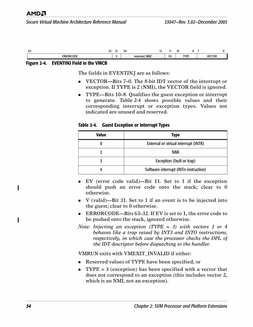
Secure Virtual Machine Architecture Reference Manual 33047—Rev. 3.02—December 2005
34 Chapter 2: SVM Processor and Platform Extensions
The fields in EVENTINJ are as follows:
VECTOR—Bits 7–0. The 8-bit IDT vector of the interrupt orexception. If TYPE is 2 (NMI), the VECTOR field is ignored.
TYPE—Bits 10–8. Qualifies the guest exception or interruptto generate. Table 2-4 shows possible values and theircorresponding interrupt or exception types. Values notindicated are unused and reserved.
EV (error code valid)—Bit 11. Set to 1 if the exceptionshould push an error code onto the stack; clear to 0otherwise.
V (valid)—Bit 31. Set to 1 if an event is to be injected intothe guest; clear to 0 otherwise.
ERRORCODE—Bits 63–32. If EV is set to 1, the error code tobe pushed onto the stack, ignored otherwise.
Note: Injecting an exception (TYPE = 3) with vectors 3 or 4behaves like a trap raised by INT3 and INTO instructions,respectively, in which case the processor checks the DPL ofthe IDT descriptor before dispatching to the handler.
VMRUN exits with VMEXIT_INVALID if either:
Reserved values of TYPE have been specified, or
TYPE = 3 (exception) has been specified with a vector thatdoes not correspond to an exception (this includes vector 2,which is an NMI, not an exception).
63 32 31 30 12 11 10 8 7 0
ERRORCODE V reserved, MBZ EV TYPE VECTOR
Figure 2-4. EVENTINJ Field in the VMCB
Table 2-4. Guest Exception or Interrupt Types
Value Type
0 External or virtual interrupt (INTR)
2 NMI
3 Exception (fault or trap)
4 Software interrupt (INTn instruction)
33047—Rev. 3.02—December 2005 Secure Virtual Machine Architecture Reference Manual
Chapter 2: SVM Processor and Platform Extensions 35
2.17 Interrupt and localAPIC Support
SVM hardware support is designed to ensure efficientvirtualization of interrupts.
2.17.1 Physical (INTR) Interrupt Masking in EFLAGS
To prevent the guest from blocking maskable interrupts(INTR), SVM provides a VMCB control bit, V_INTR_MASKING,which changes the operation of EFLAGS.IF and accesses to theTPR by means of the the CR8 register. While running a guestwith V_INTR_MASKING cleared to zero:
EFLAGS.IF controls both virtual and physical interrupts.
While running a guest with V_INTR_MASKING set to 1:
The host EFLAGS.IF at the time of the VMRUN is saved andcontrols physical interrupts while the guest is running.
The guest value of EFLAGS.IF controls virtual interruptsonly.
2.17.2 Virtualizing APIC.TPR
SVM provides a virtual TPR register, V_TPR, for use by theguest; its value is loaded from the VMCB by VMRUN andwritten back to the VMCB by #VMEXIT. The APIC's TPRalways controls the task priority for physical interrupts, and theV_TPR always controls virtual interrupts.
While running a guest with V_INTR_MASKING cleared to 0:
Writes to CR8 affect both the APIC's TPR and the V_TPRregister.
Reads from CR8 operate as they would without SVM.
While running a guest with V_INTR_MASKING set to 1:
Writes to CR8 affect only the V_TPR register.
Reads from CR8 return V_TPR.
2.17.3 TPR Access in 32-bit Mode
The mechanism for TPR virtual izat ion described inSection 2.17.2 applies only to accesses that are performed usingthe CR8 register. However, in 32-bit mode, the TPR istraditionally accessible only by using a memory-mappedregister. Typically, a VMM virtualizes such TPR accesses by notmapping the APIC page addresses in the guest. A guest accessto that region then causes a #PF intercept to the VMM, whichinspects the guest page tables to determine the physicaladdress and, after recognizing the physical address asbelonging to the APIC, finally invokes software emulation code.
Secure Virtual Machine Architecture Reference Manual 33047—Rev. 3.02—December 2005
36 Chapter 2: SVM Processor and Platform Extensions
To improve the efficiency of TPR accesses in 32-bit mode, SVMmakes CR8 available to 32-bit code by means of an alternateencoding of MOV TO/FROM CR8 (namely, MOV TO/FROM CR0with a LOCK prefix). To achieve better performance, 32-bitguests should be modified to use this access method, instead ofthe memory-mapped TPR. (For details, see “MOV (CRn)” onpage 74.)
The alternate encodings of the MOV TO/FROM CR8instructions are available even if SVM is disabled inEFER.SVME. They are available in both 64-bit and 32-bit mode.
2.17.4 Injecting Virtual (INTR) Interrupts
Virtual Interrupts allow the host to pass an interrupt (#INTR)to a guest. While inside a guest, the virtual interrupt follows thesame rules that a real interrupt follows (virtual #INTR is nottaken until EFLAGS.IF is 1, the guest's TPR has enabledinterrupts at the same priority as that of the pending virtualinterrupt).
SVM provides an efficient mechanism by which the VMM caninject virtual interrupts into a guest:
As described in Section 2.9.1, the VMM can interceptphysical interrupts that arrive while a guest is running, byactivating the INTR intercept in the VMCB.
As described in Section 2.17.4, the VMM can virtualize theinterrupt masking logic by setting the V_INTR_MASKINGbit in the VMCB.
The three VMCB fields V_IRQ, V_INTR_PRIO, andV_INTR_VECTOR indicate whether there is a virtualinterrupt pending, and, if so, what its vector number andpriority are. The VMRUN instruction loads this informationinto corresponding on-chip registers.
The processor takes a virtual INTR interrupt if
- V_IRQ and V_INTR_PRIO indicate that there is a virtualinterrupt pending whose priority is greater than thevalue in V_TPR,
- interrupts are enabled in EFLAGS.IF,
- interrupts are enabled using GIF, and
- the processor is not in an interrupt shadow (seeSection 2.17.5).
The only other difference between virtual INTR handlingand normal interrupt handling is that, in the latter case, the
33047—Rev. 3.02—December 2005 Secure Virtual Machine Architecture Reference Manual
Chapter 2: SVM Processor and Platform Extensions 37
interrupt vector is obtained from the V_INTR_VECTORregister (as opposed to running an INTAK cycle to thelocalAPIC).
The V_IGN_TPR field in the VMCB can be set to indicatethat the currently pending virtual interrupt is not subject tomasking by TPR. The priority comparison against V_TPR isomitted in this case. This mechanism can be used to injectExtINT-type interrupts into the guest.
When the processor dispatches a virtual interrupt (throughthe IDT), V_IRQ is cleared after checking for intercepts ofvirtual interrupts and before the IDT is accessed.
On #VMEXIT, V_IRQ is written back to the VMCB, allowingthe VMM to track whether a virtual interrupt has beentaken.
Physical interrupts take priority over virtual interrupts,whether they are taken directly or through a #VMEXIT.
On #VMEXIT, the processor clears its internal copies ofV_IRQ and V_INTR_MASKING, so virtual interrupts do notremain pending in the VMM, and interrupt control reverts tonormal.
2.17.5 Interrupt Shadows
The x86 architecture defines the notion of an interruptshadow—a single-instruction window during which interruptsare not recognized. For example, the instruction after an STIinstruction that sets EFLAGS.IF (from zero to one) does notrecognize interrupts or certain debug traps. The VMCBINTERRUPT_SHADOW field indicates whether the guest iscurrently in an interrupt shadow. This information is saved on#VMEXIT and loaded on VMRUN.
2.17.6 Virtual Interrupt Intercept
When virtualizing interrupt handling, a VMM typically needsonly gain control when new interrupts for a guest arrive or aregenerated, and when the guest issues an EOI (end-of-interrupt).In some circumstances, it may also be necessary for the VMM togain control at the moment interrupts become enabled in theguest (i.e., just before the guest takes a virtual interrupt). TheVMM can do so by enabling the VINTR intercept.
2.17.7 Interrupt Masking in LocalAPIC
When guests have direct access to devices, interrupts arrivingat the localAPIC can usually be dismissed only by the guest thatowns the device causing the interrupt. To prevent one guestfrom blocking other guests’ interrupts (by never processingtheir own), the VMM can mask pending interrupts in the
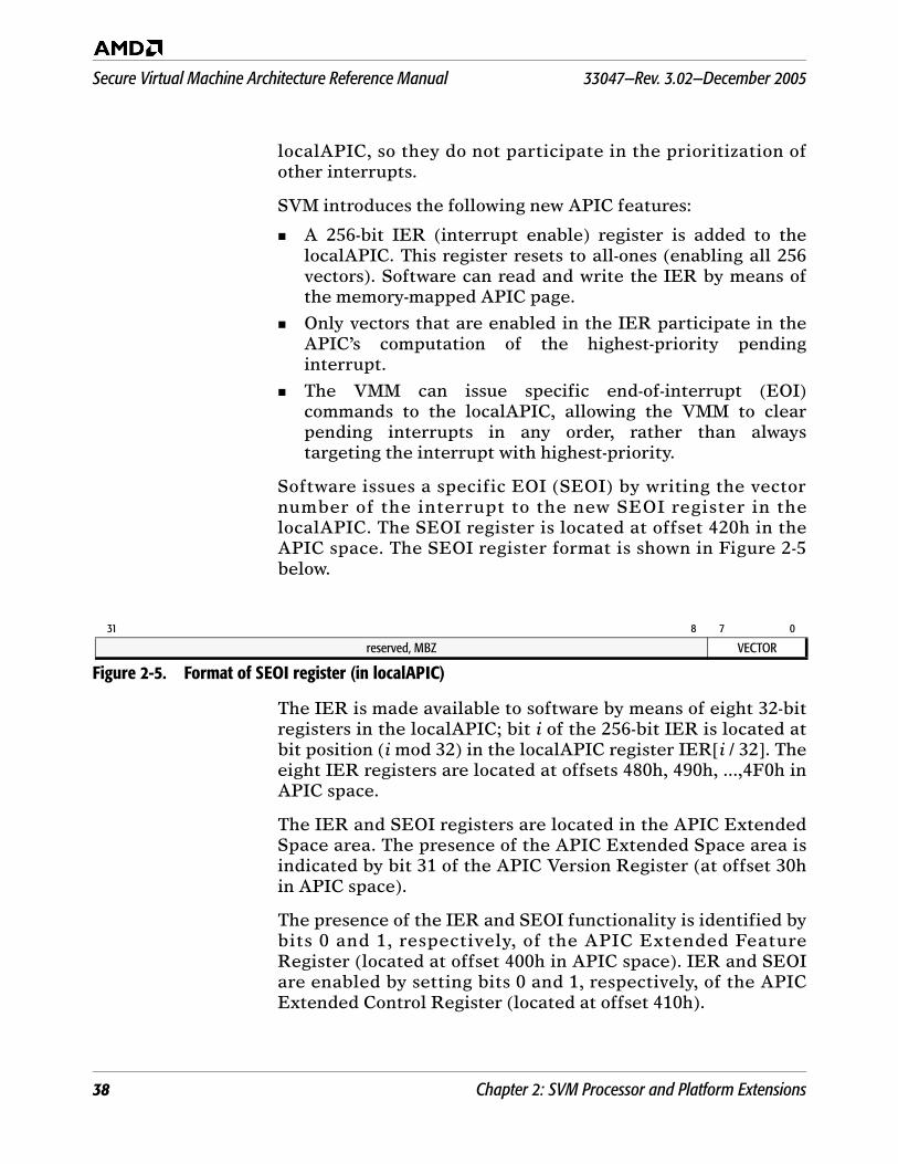
Secure Virtual Machine Architecture Reference Manual 33047—Rev. 3.02—December 2005
38 Chapter 2: SVM Processor and Platform Extensions
localAPIC, so they do not participate in the prioritization ofother interrupts.
SVM introduces the following new APIC features:
A 256-bit IER (interrupt enable) register is added to thelocalAPIC. This register resets to all-ones (enabling all 256vectors). Software can read and write the IER by means ofthe memory-mapped APIC page.
Only vectors that are enabled in the IER participate in theAPIC’s computation of the highest-priority pendinginterrupt.
The VMM can issue specific end-of-interrupt (EOI)commands to the localAPIC, allowing the VMM to clearpending interrupts in any order, rather than alwaystargeting the interrupt with highest-priority.
Software issues a specific EOI (SEOI) by writing the vectornumber of the interrupt to the new SEOI register in thelocalAPIC. The SEOI register is located at offset 420h in theAPIC space. The SEOI register format is shown in Figure 2-5below.
The IER is made available to software by means of eight 32-bitregisters in the localAPIC; bit i of the 256-bit IER is located atbit position (i mod 32) in the localAPIC register IER[i / 32]. Theeight IER registers are located at offsets 480h, 490h, ...,4F0h inAPIC space.
The IER and SEOI registers are located in the APIC ExtendedSpace area. The presence of the APIC Extended Space area isindicated by bit 31 of the APIC Version Register (at offset 30hin APIC space).
The presence of the IER and SEOI functionality is identified bybits 0 and 1, respectively, of the APIC Extended FeatureRegister (located at offset 400h in APIC space). IER and SEOIare enabled by setting bits 0 and 1, respectively, of the APICExtended Control Register (located at offset 410h).
31 8 7 0
reserved, MBZ VECTOR
Figure 2-5. Format of SEOI register (in localAPIC)
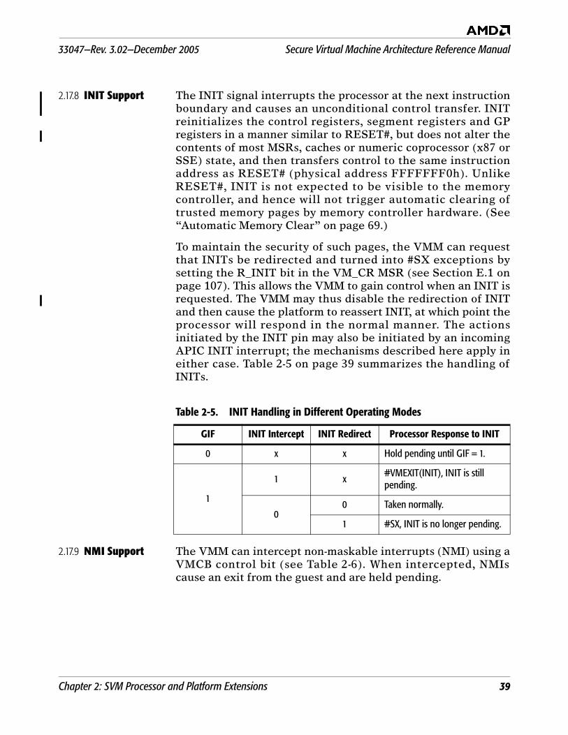
33047—Rev. 3.02—December 2005 Secure Virtual Machine Architecture Reference Manual
Chapter 2: SVM Processor and Platform Extensions 39
2.17.8 INIT Support The INIT signal interrupts the processor at the next instructionboundary and causes an unconditional control transfer. INITreinitializes the control registers, segment registers and GPregisters in a manner similar to RESET#, but does not alter thecontents of most MSRs, caches or numeric coprocessor (x87 orSSE) state, and then transfers control to the same instructionaddress as RESET# (physical address FFFFFFF0h). UnlikeRESET#, INIT is not expected to be visible to the memorycontroller, and hence will not trigger automatic clearing oftrusted memory pages by memory controller hardware. (See“Automatic Memory Clear” on page 69.)
To maintain the security of such pages, the VMM can requestthat INITs be redirected and turned into #SX exceptions bysetting the R_INIT bit in the VM_CR MSR (see Section E.1 onpage 107). This allows the VMM to gain control when an INIT isrequested. The VMM may thus disable the redirection of INITand then cause the platform to reassert INIT, at which point theprocessor will respond in the normal manner. The actionsinitiated by the INIT pin may also be initiated by an incomingAPIC INIT interrupt; the mechanisms described here apply ineither case. Table 2-5 on page 39 summarizes the handling ofINITs.
2.17.9 NMI Support The VMM can intercept non-maskable interrupts (NMI) using aVMCB control bit (see Table 2-6). When intercepted, NMIscause an exit from the guest and are held pending.
Table 2-5. INIT Handling in Different Operating Modes
GIF INIT Intercept INIT Redirect Processor Response to INIT
0 x x Hold pending until GIF = 1.
1
1 x #VMEXIT(INIT), INIT is still pending.
00 Taken normally.
1 #SX, INIT is no longer pending.

Secure Virtual Machine Architecture Reference Manual 33047—Rev. 3.02—December 2005
40 Chapter 2: SVM Processor and Platform Extensions
2.18 SMM Support
This section describes SVM support for virtualization of SystemManagement Mode (SMM).
2.18.1 Sources of SMI Various events can cause an assertion of a system managementinterrupt (SMI); these are classified into three categories
Internal, synchronous (also known as I/O Trapping)—implementation-specific IOIO or config space trapping inthe CPU itself; always synchronous in response to an IN orOUT instruction. I/O Trapping is set up by means of MSRsand can be brought under the control of the VMM byintercepting guest access to those MSRs.
External, synchronous—IOIO trapping in response to (andsynchronous with) IN or OUT instructions, but generated byan external agent (typically the Southbridge).
External, asynchronous—generated externally in responseto an external, physical event, e.g., closing a laptop lid,temperature sensor triggering, etc.
2.18.2 Response to SMI
How hardware responds to SMIs is a function of whether SMMinterrupts are being intercepted and whether interrupts areenabled globally, as shown in Table 2-7.
Table 2-6. NMI Handling in Different Operating Modes
GIF NMI Intercept Processor Response to NMI
0 X Hold pending until GIF=1.
11 #VMEXIT(NMI), NMI is still pending.
0 Taken normally.
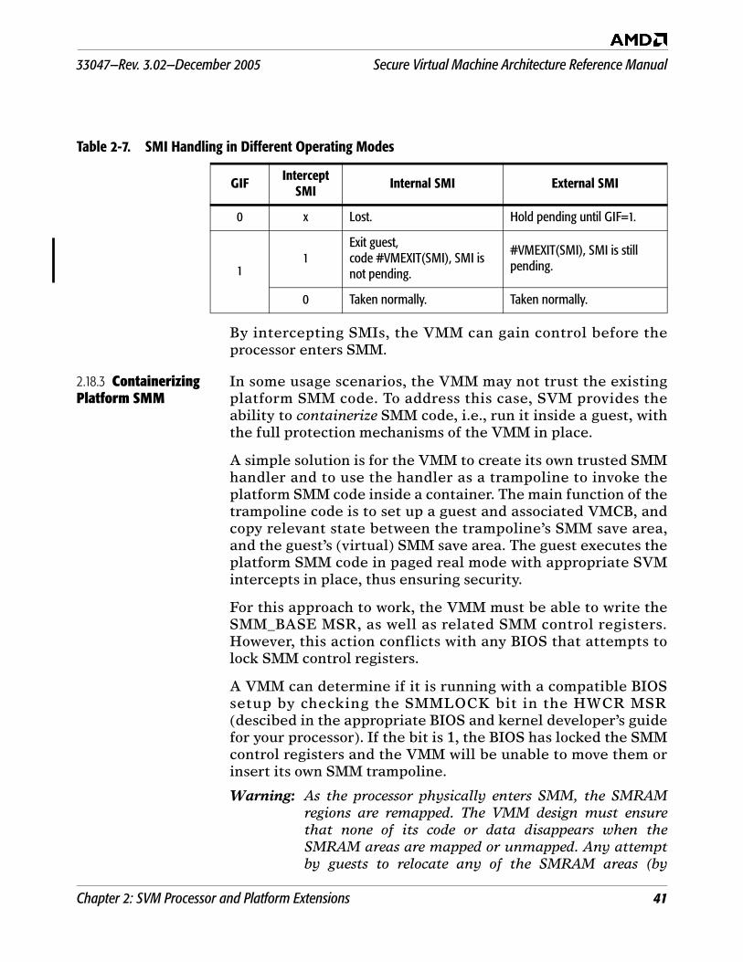
33047—Rev. 3.02—December 2005 Secure Virtual Machine Architecture Reference Manual
Chapter 2: SVM Processor and Platform Extensions 41
By intercepting SMIs, the VMM can gain control before theprocessor enters SMM.
2.18.3 Containerizing Platform SMM
In some usage scenarios, the VMM may not trust the existingplatform SMM code. To address this case, SVM provides theability to containerize SMM code, i.e., run it inside a guest, withthe full protection mechanisms of the VMM in place.
A simple solution is for the VMM to create its own trusted SMMhandler and to use the handler as a trampoline to invoke theplatform SMM code inside a container. The main function of thetrampoline code is to set up a guest and associated VMCB, andcopy relevant state between the trampoline’s SMM save area,and the guest’s (virtual) SMM save area. The guest executes theplatform SMM code in paged real mode with appropriate SVMintercepts in place, thus ensuring security.
For this approach to work, the VMM must be able to write theSMM_BASE MSR, as well as related SMM control registers.However, this action conflicts with any BIOS that attempts tolock SMM control registers.
A VMM can determine if it is running with a compatible BIOSsetup by checking the SMMLOCK bit in the HWCR MSR(descibed in the appropriate BIOS and kernel developer’s guidefor your processor). If the bit is 1, the BIOS has locked the SMMcontrol registers and the VMM will be unable to move them orinsert its own SMM trampoline.
Warning: As the processor physically enters SMM, the SMRAMregions are remapped. The VMM design must ensurethat none of its code or data disappears when theSMRAM areas are mapped or unmapped. Any attemptby guests to relocate any of the SMRAM areas (by
Table 2-7. SMI Handling in Different Operating Modes
GIF InterceptSMI Internal SMI External SMI
0 x Lost. Hold pending until GIF=1.
11
Exit guest,code #VMEXIT(SMI), SMI is not pending.
#VMEXIT(SMI), SMI is still pending.
0 Taken normally. Taken normally.
Secure Virtual Machine Architecture Reference Manual 33047—Rev. 3.02—December 2005
42 Chapter 2: SVM Processor and Platform Extensions
means of certain MSR writes) must also be interceptedto prevent malicious SMM code from interfering withVMM operation.
Advanced Support. For more efficient and flexible operation, thenew SMM_CTL MSR (described in more detail in Section E.3 onpage 108) is designed to allow the VMM to control explicitly:
when SMI is acknowledged or deasserted to the chipset,
when SMM is considered active (i.e., SMRAM areas aremapped, NMIs and various other interrupts are blocked),and
when the SMI-pending flag is cleared in the processor.
With this hardware support, the VMM can enter and exit SMMat will and the VMM code should be simplified.
Note: Writes to the SMM_CTL MSR cause a #GP if the BIOS haslocked the SMM control registers. Otherwise, SMM_CTL canbe used to inspect the SMRAM areas at will, which risksrevealing secrets that the BIOS might intend to hide.
2.19 Last Branch Record Virtualization
The AMD64 debug control MSR (DebugCtl) provides theprocessor control of control-transfer recording and other debugtasks. (See “Debug and Performance Resources” in the AMD64Architecture Programmer’s Manual , Volume 2: SystemProgramming, order #24593, for more detailed information onthese subjects.) Software sets the last-branch record(DebugCtl.LBR) bit to 1 to cause the processor to record thesource and target addresses of the last control transfer takenbefore a debug exception. These control transfers includebranch instructions, interrupts, and exceptions. Recordedinformation is stored in four MSRs:
LastBranchFromIP—Holds the segment offset of the sourceinstruction pointer (rIP).
LastBranchToIP—Holds the segment offset of the target rIP.
LastExceptionFromIP—Updated with the previous value ofLastBranchFromIP during interrupts and exceptions (except#DB exceptions caused by debug breakpoint and ICEBP).
33047—Rev. 3.02—December 2005 Secure Virtual Machine Architecture Reference Manual
Chapter 2: SVM Processor and Platform Extensions 43
LastExceptionToIP—Updated with the previous value ofLastBranchToIP during interrupts and exceptions (except#DB exceptions caused by debug breakpoint and ICEBP).
Under SVM, the contents of the control-transfer recordingMSRs must be exchanged between values tracked by host andand guest. This is done by activating LBR virtualization in theguest VMCB control area.
2.19.1 Enabling LBR Virualization
Setting the LBR_VIRTUALIZATION_ENABLE bit to 1 in theVMCB control area enables LBR virtualization. When LBRvirtualization is enabled, the VMM stores an image of theDebugCtl MSR and of each of the pointers stored in the control-transfer recording MSRs in four fields in the VMCB state savearea.
DBGCTL—Holds the guest value of the DebugCTL MSR.
BR_FROM—Holds the guest value of the LastBranchFromIPMSR.
BR_TO—Holds the guest value of the LastBranchToIP MSR.
LASTEXCPFROM—Holds the guest value of theLastExceptionToIP MSR.
LASTEXCPTO—Holds the guest value of theLastExceptionFromIP MSR.
2.19.2 Host and Guest LBR Virtualization
When VMCB.LBR_VIRTUALIZATION_ENABLE[0] is set,VMRUN saves all five host control-transfer MSRs in the hostsave area, and then loads the same five MSRS for the guest fromthe VMCB save area. Similarly, #VMEXIT saves the guest'sMSRs and loads the host's MSRs to and from their respectivesave areas.
2.19.3 LBR Virtualization CPUID Feature Detection
EDX bit 1 as returned by CPUID extended function8000_000Ah reports the LBR virtualization feature on AMD64processors.
2.20 External Access Protection
By securing the virtual address translation mechanism, theVMM can restrict guest CPU accesses to memory. However,should the guest have direct access to DMA-capable devices, anadditional protection mechanism is required. SVM providesmultiple protection domains which can restrict device access tophysical memory on a per-page basis. This is accomplished via
Secure Virtual Machine Architecture Reference Manual 33047—Rev. 3.02—December 2005
44 Chapter 2: SVM Processor and Platform Extensions
control logic in the Northbridge’s host bridge which governs anyexternal access port (e.g., PCI or HyperTransport™ technologyinterfaces).
2.20.1 Device IDs and Protection Domains
The Northbridge’s host bridge provides a number of protectiondomains. Each protection domain has associated with it a deviceexclusion vector (DEV) that specifies the per-page access rightsof devices in that domain. Devices are identified by aHyperTransport™ bus/unitID (device ID) and the host bridgecontains a lookup table of fixed size that maps device IDs to aprotection domain.
2.20.2 Device Exclusion Vector (DEV)
A DEV is a contiguous array of bits in physical memory; each bitin the DEV (in little-endian order) corresponds to one 4-Kbytepage in physical memory.
The physical address of the base of a DEV must be 4-Kbyte-aligned and stored in one of the DEVBASE registers, which areaccessed through an indirection mechanism in the DEVCTLPCI Configuration Space function block in the host bridge (see“DEV Control and Status Registers” on page 48). The DEVprotection hardware is not operational until enabled by settinga control bit in the DEV Control Register, also in the DEVCTLfunction block.
Note: The DEV may have to cover part of MMIO space beyond theDRAM. Especially in 64-bit systems, the operating systemshould map MMIO space starting immediately after theDRAM area and building up, as opposed to starting downfrom the maximum physical address.
Host Bridge and Processor DEV Caching. For improved performance,the host bridge may cache portions of the DEV. Any suchcached information can be invalidated by setting theDEV_FLUSH flag in the DEV control register to 1. Softwaremust set this flag after modifying DEV contents to ensure thatthe protection logic uses the updated values. The host bridgeautomatically clears this flag when the flush operationcompletes. After setting this flag, software should monitor ituntil it has cleared, in order to synchronize DEV updates withsubsequent activity.
By default, the host bridge probes the processor caches for thelatest data when it accesses the DEV in DRAM. However, it ispossible to disable probing by means of the DEV_CR register(see “DEV_CR Register” on page 49); this is recommended in
33047—Rev. 3.02—December 2005 Secure Virtual Machine Architecture Reference Manual
Chapter 2: SVM Processor and Platform Extensions 45
the case of unified memory architecture (UMA) graphicssystems. If cache probing is disabled, host bridge reads of theDEV will not check processor caches for more recent copies.This requires software on the CPU to map the memorycontaining the DEV as uncacheable (UC) or write-through(WT). Alternatively, software must perform a CLFLUSH beforeit can expect a change to the DEV to be visible by theNorthbridge (and before software flushes the DEV cache in thehost controller).
Multiprocessor Issues. Device-originated memory requests arechecked against the DEV at the point of entry to the system—the Northbridge to which the device is physically attached.Each Northbridge can have its own set of domains, device-to-domain mappings, and DEV tables (e.g., domain #2 on one nodecan encompass different devices, and can have different accessrights than domain #2 on another node). Thus, the number ofprotection domains available to software can scale with thenumber of Northbridges in the system.
2.20.3 Access Checking
Memory Space Accesses. When a memory-space read or writerequest is received on an external host bridge port, the hostbridge maps the HyperTransport bus device ID to a protectiondomain number, which in turn selects the DEV defining theaccess permissions for the device (see Figure 2-6 on page 46).The host bridge then checks the memory address against theDEV contents by indexing into the DEV with the PFN portionof the address (bits 39–12). The PFN is used as a bit indexwithin the DEV. If the bit read from the DEV is set to 1, the hostbridge inhibits the access by returning all ones for the data for aread request, or suppressing the store operation on a writerequest. A Master Abort error response will be returned to therequesting device.
Peer-to-peer memory accesses routed up to the host bridge arealso subjected to checks against the DEV. Peer-to-peer transfersthat may be occurring behind bridges are not checked.
DEV checks are applied before addresses are translated by theGART. The DEV table is never consulted by accessesoriginating in the CPU.
I/O Space Accesses. The host bridge can be configured to reject allI/O space accesses from devices, by setting the IOSPE bit in the
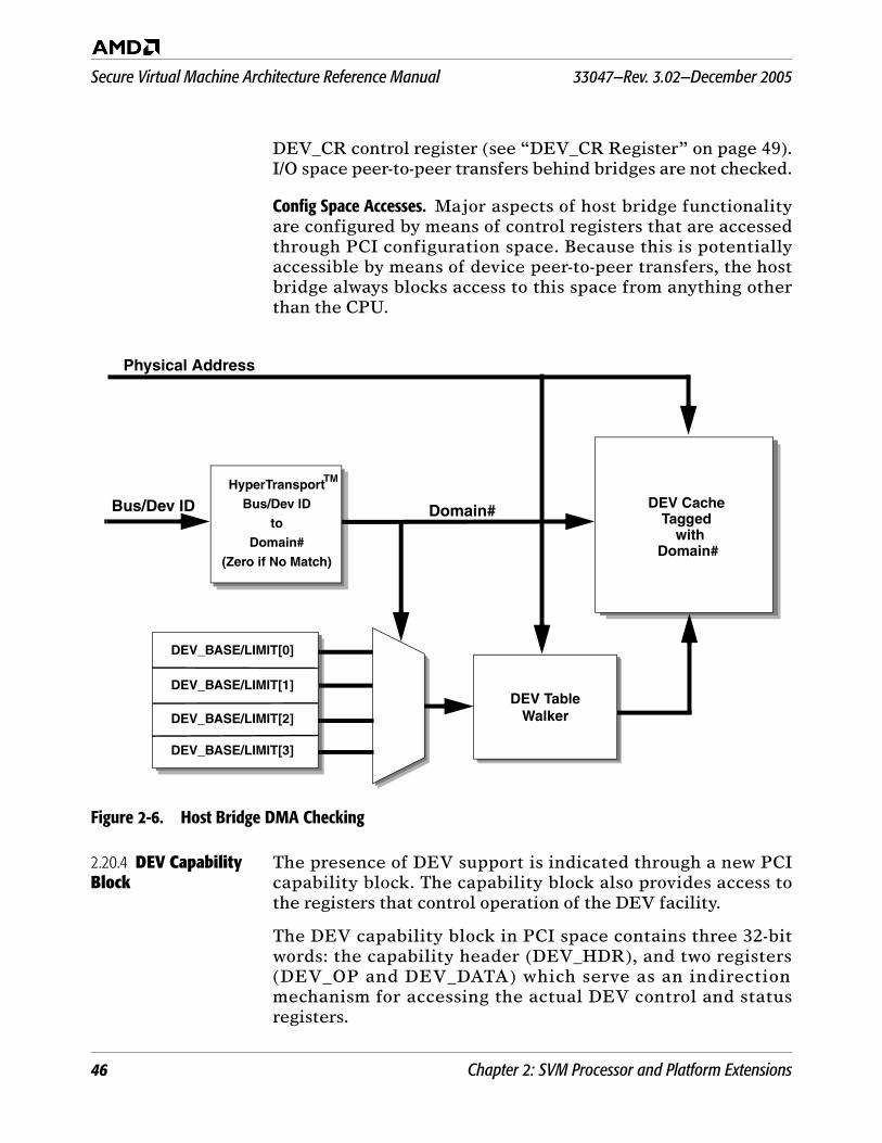
Secure Virtual Machine Architecture Reference Manual 33047—Rev. 3.02—December 2005
46 Chapter 2: SVM Processor and Platform Extensions
DEV_CR control register (see “DEV_CR Register” on page 49).I/O space peer-to-peer transfers behind bridges are not checked.
Config Space Accesses. Major aspects of host bridge functionalityare configured by means of control registers that are accessedthrough PCI configuration space. Because this is potentiallyaccessible by means of device peer-to-peer transfers, the hostbridge always blocks access to this space from anything otherthan the CPU.
Figure 2-6. Host Bridge DMA Checking
2.20.4 DEV Capability Block
The presence of DEV support is indicated through a new PCIcapability block. The capability block also provides access tothe registers that control operation of the DEV facility.
The DEV capability block in PCI space contains three 32-bitwords: the capability header (DEV_HDR), and two registers(DEV_OP and DEV_DATA) which serve as an indirectionmechanism for accessing the actual DEV control and statusregisters.
DEV Cache
with Domain#
Tagged
DEV TableWalker
HyperTransport
toDomain#
(Zero if No Match)
Bus/Dev ID
Physical Address
DEV_BASE/LIMIT[0]
DEV_BASE/LIMIT[1]
DEV_BASE/LIMIT[2]
DEV_BASE/LIMIT[3]
Domain#Bus/Dev ID
TM
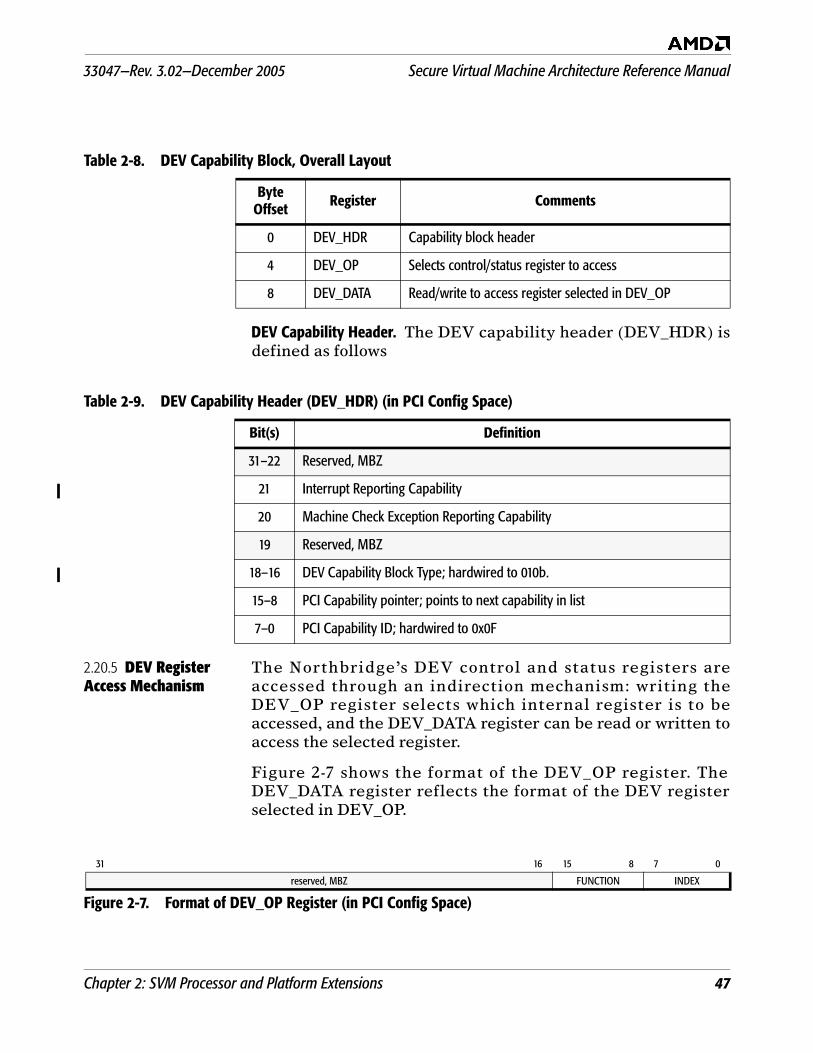
33047—Rev. 3.02—December 2005 Secure Virtual Machine Architecture Reference Manual
Chapter 2: SVM Processor and Platform Extensions 47
DEV Capability Header. The DEV capability header (DEV_HDR) isdefined as follows
2.20.5 DEV Register Access Mechanism
The Northbridge’s DEV control and status registers areaccessed through an indirection mechanism: writing theDEV_OP register selects which internal register is to beaccessed, and the DEV_DATA register can be read or written toaccess the selected register.
Figure 2-7 shows the format of the DEV_OP register. TheDEV_DATA register reflects the format of the DEV registerselected in DEV_OP.
Table 2-8. DEV Capability Block, Overall Layout
Byte Offset Register Comments
0 DEV_HDR Capability block header
4 DEV_OP Selects control/status register to access
8 DEV_DATA Read/write to access register selected in DEV_OP
Table 2-9. DEV Capability Header (DEV_HDR) (in PCI Config Space)
Bit(s) Definition
31–22 Reserved, MBZ
21 Interrupt Reporting Capability
20 Machine Check Exception Reporting Capability
19 Reserved, MBZ
18–16 DEV Capability Block Type; hardwired to 010b.
15–8 PCI Capability pointer; points to next capability in list
7–0 PCI Capability ID; hardwired to 0x0F
31 16 15 8 7 0
reserved, MBZ FUNCTION INDEX
Figure 2-7. Format of DEV_OP Register (in PCI Config Space)
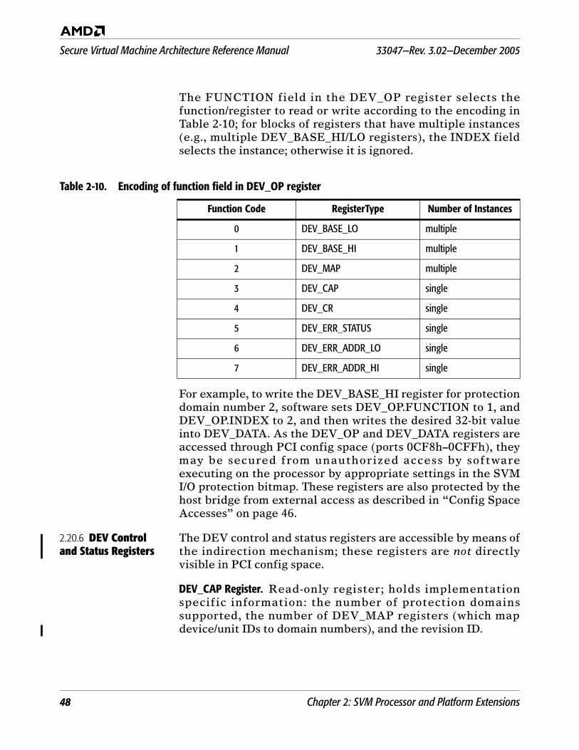
Secure Virtual Machine Architecture Reference Manual 33047—Rev. 3.02—December 2005
48 Chapter 2: SVM Processor and Platform Extensions
The FUNCTION field in the DEV_OP register selects thefunction/register to read or write according to the encoding inTable 2-10; for blocks of registers that have multiple instances(e.g., multiple DEV_BASE_HI/LO registers), the INDEX fieldselects the instance; otherwise it is ignored.
For example, to write the DEV_BASE_HI register for protectiondomain number 2, software sets DEV_OP.FUNCTION to 1, andDEV_OP.INDEX to 2, and then writes the desired 32-bit valueinto DEV_DATA. As the DEV_OP and DEV_DATA registers areaccessed through PCI config space (ports 0CF8h–0CFFh), theymay be secured from unauthorized access by softwareexecuting on the processor by appropriate settings in the SVMI/O protection bitmap. These registers are also protected by thehost bridge from external access as described in “Config SpaceAccesses” on page 46.
2.20.6 DEV Control and Status Registers
The DEV control and status registers are accessible by means ofthe indirection mechanism; these registers are not directlyvisible in PCI config space.
DEV_CAP Register. Read-only register; holds implementationspecific information: the number of protection domainssupported, the number of DEV_MAP registers (which mapdevice/unit IDs to domain numbers), and the revision ID.
Table 2-10. Encoding of function field in DEV_OP register
Function Code RegisterType Number of Instances
0 DEV_BASE_LO multiple
1 DEV_BASE_HI multiple
2 DEV_MAP multiple
3 DEV_CAP single
4 DEV_CR single
5 DEV_ERR_STATUS single
6 DEV_ERR_ADDR_LO single
7 DEV_ERR_ADDR_HI single
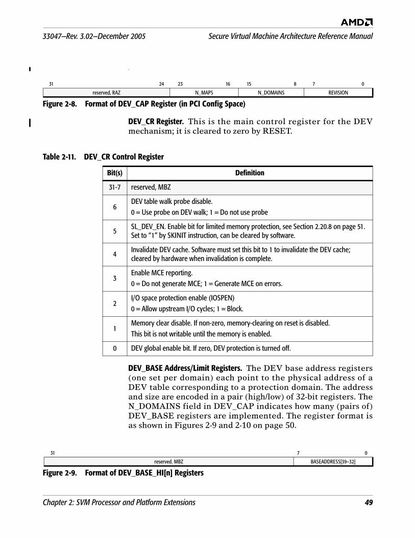
33047—Rev. 3.02—December 2005 Secure Virtual Machine Architecture Reference Manual
Chapter 2: SVM Processor and Platform Extensions 49
.
DEV_CR Register. This is the main control register for the DEVmechanism; it is cleared to zero by RESET.
DEV_BASE Address/Limit Registers. The DEV base address registers(one set per domain) each point to the physical address of aDEV table corresponding to a protection domain. The addressand size are encoded in a pair (high/low) of 32-bit registers. TheN_DOMAINS field in DEV_CAP indicates how many (pairs of)DEV_BASE registers are implemented. The register format isas shown in Figures 2-9 and 2-10 on page 50.
31 24 23 16 15 8 7 0
reserved, RAZ N_MAPS N_DOMAINS REVISION
Figure 2-8. Format of DEV_CAP Register (in PCI Config Space)
Table 2-11. DEV_CR Control Register
Bit(s) Definition
31-7 reserved, MBZ
6DEV table walk probe disable.0 = Use probe on DEV walk; 1 = Do not use probe
5SL_DEV_EN. Enable bit for limited memory protection, see Section 2.20.8 on page 51. Set to “1” by SKINIT instruction, can be cleared by software.
4 Invalidate DEV cache. Software must set this bit to 1 to invalidate the DEV cache; cleared by hardware when invalidation is complete.
3Enable MCE reporting.0 = Do not generate MCE; 1 = Generate MCE on errors.
2I/O space protection enable (IOSPEN)0 = Allow upstream I/O cycles; 1 = Block.
1Memory clear disable. If non-zero, memory-clearing on reset is disabled. This bit is not writable until the memory is enabled.
0 DEV global enable bit. If zero, DEV protection is turned off.
31 7 0
reserved. MBZ BASEADDRESS[39–32]
Figure 2-9. Format of DEV_BASE_HI[n] Registers
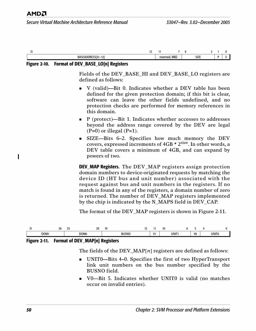
Secure Virtual Machine Architecture Reference Manual 33047—Rev. 3.02—December 2005
50 Chapter 2: SVM Processor and Platform Extensions
Fields of the DEV_BASE_HI and DEV_BASE_LO registers aredefined as follows:
V (valid)—Bit 0. Indicates whether a DEV table has beendefined for the given protection domain; if this bit is clear,software can leave the other fields undefined, and noprotection checks are performed for memory references inthis domain.
P (protect)—Bit 1. Indicates whether accesses to addressesbeyond the address range covered by the DEV are legal(P=0) or illegal (P=1).
SIZE—Bits 6–2. Specifies how much memory the DEVcovers, expressed increments of 4GB * 2size. In other words, aDEV table covers a minimum of 4GB, and can expand bypowers of two.
DEV_MAP Registers. The DEV_MAP registers assign protectiondomain numbers to device-originated requests by matching thedevice ID (HT bus and unit number) associated with therequest against bus and unit numbers in the registers. If nomatch is found in any of the registers, a domain number of zerois returned. The number of DEV_MAP registers implementedby the chip is indicated by the N_MAPS field in DEV_CAP.
The format of the DEV_MAP registers is shown in Figure 2-11.
The fields of the DEV_MAP[n] registers are defined as follows:
UNIT0—Bits 4–0. Specifies the first of two HyperTransportlink unit numbers on the bus number specified by theBUSNO field.
V0—Bit 5. Indicates whether UNIT0 is valid (no matchesoccur on invalid entries).
31 12 11 7 6 2 1 0
BASEADDRESS[31–12] reserved, MBZ SIZE P V
Figure 2-10. Format of DEV_BASE_LO[n] Registers
31 26 25 20 19 12 11 10 6 5 4 0
DOM1 DOM0 BUSNO V1 UNIT1 V0 UNIT0
Figure 2-11. Format of DEV_MAP[n] Registers
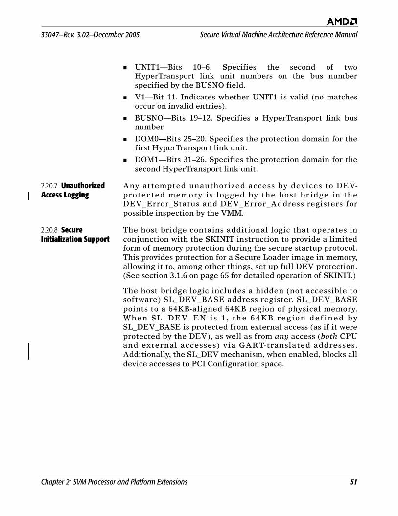
33047—Rev. 3.02—December 2005 Secure Virtual Machine Architecture Reference Manual
Chapter 2: SVM Processor and Platform Extensions 51
UNIT1—Bits 10–6. Specifies the second of twoHyperTransport link unit numbers on the bus numberspecified by the BUSNO field.
V1—Bit 11. Indicates whether UNIT1 is valid (no matchesoccur on invalid entries).
BUSNO—Bits 19–12. Specifies a HyperTransport link busnumber.
DOM0—Bits 25–20. Specifies the protection domain for thefirst HyperTransport link unit.
DOM1—Bits 31–26. Specifies the protection domain for thesecond HyperTransport link unit.
2.20.7 Unauthorized Access Logging
Any attempted unauthorized access by devices to DEV-protected memory is logged by the host bridge in theDEV_Error_Status and DEV_Error_Address registers forpossible inspection by the VMM.
2.20.8 Secure Initialization Support
The host bridge contains additional logic that operates inconjunction with the SKINIT instruction to provide a limitedform of memory protection during the secure startup protocol.This provides protection for a Secure Loader image in memory,allowing it to, among other things, set up full DEV protection.(See section 3.1.6 on page 65 for detailed operation of SKINIT.)
The host bridge logic includes a hidden (not accessible tosoftware) SL_DEV_BASE address register. SL_DEV_BASEpoints to a 64KB-aligned 64KB region of physical memory.When SL_DEV_EN is 1 , the 64KB region defined bySL_DEV_BASE is protected from external access (as if it wereprotected by the DEV), as well as from any access (both CPUand external accesses) via GART-translated addresses.Additionally, the SL_DEV mechanism, when enabled, blocks alldevice accesses to PCI Configuration space.

Secure Virtual Machine Architecture Reference Manual 33047—Rev. 3.02—December 2005
52 Chapter 2: SVM Processor and Platform Extensions
2.21 Nested Paging Facility
The optional SVM nested paging facility provides for two levelsof address translation, thus eliminating the need for the VMMto maintain shadow page tables.
2.21.1 Traditional Paging versus Nested Paging
Figure 2-12 shows how a page in the virtual address space ismapped to a page in the physical address space in traditional(single-level) address translation. Control register CR3 containsthe physical address of the base of the page tables (PT,represented by the shaded box in the figure), which governs theaddress translation.
Figure 2-12. Address Translation with Traditional Paging
With nested paging enabled, two levels of address translationare applied; refer to Figure 2-13 below.
Both guest and host levels have their own copy of CR3,referred to as gCR3 and hCR3, respectively.
Guest page tables (gPT) map guest virtual addresses toguest physical addresses. The guest page tables are in guestphysical memory, and are pointed to by gCR3.
Host page tables (hPT) map guest physical addresses to hostphysical addresses. The host page tables are in host physicalmemory, and are pointed to by hCR3.
The most-recently used translations from guest virtual tohost physical address are cached in the TLB and used onsubsequent guest accesses.
It is important to note that gCR3 and the guest page tableentries contain guest physical addresses, not host physical
Virtual Space
PT
0
0
CR3
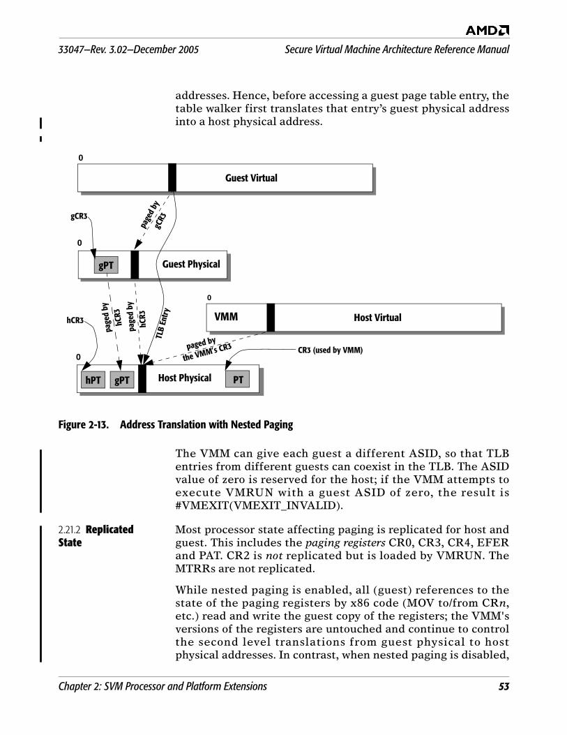
33047—Rev. 3.02—December 2005 Secure Virtual Machine Architecture Reference Manual
Chapter 2: SVM Processor and Platform Extensions 53
addresses. Hence, before accessing a guest page table entry, thetable walker first translates that entry’s guest physical addressinto a host physical address.
Figure 2-13. Address Translation with Nested Paging
The VMM can give each guest a different ASID, so that TLBentries from different guests can coexist in the TLB. The ASIDvalue of zero is reserved for the host; if the VMM attempts toexecute VMRUN with a guest ASID of zero, the result is#VMEXIT(VMEXIT_INVALID).
2.21.2 Replicated State
Most processor state affecting paging is replicated for host andguest. This includes the paging registers CR0, CR3, CR4, EFERand PAT. CR2 is not replicated but is loaded by VMRUN. TheMTRRs are not replicated.
While nested paging is enabled, all (guest) references to thestate of the paging registers by x86 code (MOV to/from CRn,etc.) read and write the guest copy of the registers; the VMM'sversions of the registers are untouched and continue to controlthe second level translations from guest physical to hostphysical addresses. In contrast, when nested paging is disabled,
Guest Virtual
gPT
0
0
Host Virtual
0
hPT
0
Guest Physical
page
d by
gCR3gCR3
hCR3
PT
CR3 (used by VMM)
Host Physical
paged by
the VMM’s CR3
page
d by
hCR3
TLB
Entr
y
VMM
gPT
page
d by
hCR3
Secure Virtual Machine Architecture Reference Manual 33047—Rev. 3.02—December 2005
54 Chapter 2: SVM Processor and Platform Extensions
the VMM's paging control registers are stored in the host statesave area and the paging control registers from the guest VMCBare the only active versions of those registers.
2.21.3 Enabling Nested Paging
The VMRUN instruction enables nested paging when theNP_ENABLE bit in the VMCB is set to 1. The VMCB containsthe hCR3 value for the page tables for the extra translation. Theextra translation uses the same paging mode as the VMM usedwhen it executed the most recent VMRUN.
Nested paging is automatically disabled by #VMEXIT.
Nested paging is allowed only if the host has paging enabled. IfVMRUN is executed with hCR0.PG cleared to zero andNP_ENABLE set to 1 , VMRUN terminates with#VMEXIT(VMEXIT_INVALID).
2.21.4 Nested Paging and VMRUN/#VMEXIT
When VMRUN is executed with nested paging enabled(NP_ENABLE = 1), the paging registers are affected as follows:
VMRUN saves the VMM’s CR3 in the host save area.
VMRUN loads the guest paging state from the guest VMCBinto the guest registers (i.e., VMRUN loads CR3 with theVMCB CR3 field, etc). The guest PAT register is loaded fromG_PAT field in the VMCB.
VMRUN loads hCR3, the version of CR3 to be used while thenested-paging guest is running, from the H_CR3 field in theVMCB. The other host paging-control bits (hCR4.PAE, etc)remain the same as they were in the VMM at the timeVMRUN was executed.
When #VMEXIT occurs with nested paging enabled:
#VMEXIT writes the guest paging state (gCR3, gCR0, etc)back into the VMCB. hCR3 is not saved back into the VMCB.
#VMEXIT need not reload any host paging state other thanCR3 from the host save area, though an implementation isfree to do so.
2.21.5 Nested Table Walk
When the guest is running with nested paging enabled, a TLBmiss causes several nested table walks:
Guest Page Tables—the gCR3 register specifies a guestphysical address, as do the entries in the the guest's pagetables. These guest physical addresses must be translated tohost physical addresses using the host page tables. Host-
33047—Rev. 3.02—December 2005 Secure Virtual Machine Architecture Reference Manual
Chapter 2: SVM Processor and Platform Extensions 55
level faults can occur on these accesses, including writefaults due to setting of accessed and dirty bits in the guestpage table.
Final Guest-Physical Page—once a guest virtual to guestphysical mapping is known, guest permissions can bechecked. If the guest page tables allow the access, the guestphysical address is walked in the host page tables to find thehost physical address.
Table walks for guest page tables are always treated as userwrites at the host level. For this reason,
the page must be writable by user at the host level, or else a#VMEXIT(NPF) is raised, and
the dirty and accessed bits are always set in the host pagetable entries that were touched during nested page tablewalks for guest page table entries.
A table walk for the guest page itself is always treated as a useraccess at the host level, but is treated as a data read, data write,or code read, depending on the guest access.
If the guest has paging disabled (gCR0.PG = 0), there are noguest page table entries to be translated in the host page tables.In this case, the final guest-physical address is equal to theguest-virtual address, and is still translated in the host pagetables.
2.21.6 Host versus Guest Page Faults, Fault Ordering
In nested paging, page faults can be raised at either the guest orhost level. Nested walks proceed in the following order; faultsare generated in the same order:
1. Walk the guest page table entries in the host page tables.Host dirty/accessed bits are set as needed in the host pagetables. Any host page faults result in #VMEXIT(NPF).
2. As the guest page table walk proceeds from the top of thepage table to the last entry, any not-present entries orreserved bits in the guest page table entries at each level ofthe guest walk cause #PF in the guest. Guest dirty andaccessed bits are set as needed in the guest page tablesduring the walk. Steps 1 and 2 are repeated for each level ofthe guest page table that is traversed.
3. Once the guest physical address for the guest access hasbeen determined, check the guest permissions; any fault atthis point causes a #PF in the guest.
Secure Virtual Machine Architecture Reference Manual 33047—Rev. 3.02—December 2005
56 Chapter 2: SVM Processor and Platform Extensions
4. Perform the final translation from guest physical to hostphysical using the host page table; any fault during thistranslation results in a #VMEXIT(NPF).
Host faults are entirely a function of the host page tables andVMM processor mode. Host faults cause a #VMEXIT(NPF) tothe VMM. The faulting guest physical address is saved in theVMCB's EXITINFO2 field; EXITINFO1 delivers an error codesimilar to a #PF errorcode:
Bit 0 (P)—cleared to 0 if the host page was not present, 1otherwise
Bit 1 (RW)—set to 1 if the host-level access was a write. Notethat host table walks for guest page tables are always treatedas data writes.
Bit 2 (US)—always 1, since all guest accesses are treated asuser accesses at the host level
Bit 3 (RSV)—set to 1 if reserved bits were set in thecorresponding host page table entry
Bit 4 (ID)—set to 1 if the host-level access was a code read.Note that host table walks for guest page tables are alwaystreated as data writes, even if the access itself is a code read
Guest faults are entirely a function of the guest page tables andprocessor mode; they are delivered to the guest as normal #PFexceptions without any VMM intervention, unless the VMM isintercepting guest #PF exceptions.
2.21.7 Combining Host and Guest Attributes
Any access to guest physical memory is subjected to a hostpermission check by examining the host’s mapping of the hostvirtual address corresponding to the guest physical addressunder consideration.
A page is considered writable by the guest only if it is markedwritable at both the guest and host levels. Note that the guest’sgCR0.WP affects only the interpretation of the guest page tableentry; setting gCR0.WP cannot make a page writable at anyCPL in the guest if the page is marked read-only in the hostpage tables. The host hCR0.WP bit is ignored under nestedpaging.
A page is considered executable by the guest only if it is markedexecutable at both the guest and host levels. If the EFER.NXEbit is cleared for the guest, all guest pages are executable at the
33047—Rev. 3.02—December 2005 Secure Virtual Machine Architecture Reference Manual
Chapter 2: SVM Processor and Platform Extensions 57
guest level. Similarly, if the EFER.NXE bit is cleared for thehost, all host pages are executable at the host level.
Some attributes are taken from the guest page tables andoperating modes only. A page is considered global within theguest only if is marked global in the guest page tables; the hostpage table entry and host hCR4.PGE are irrelevant. Globalpages are only global within their ASID.
A page is considered user in the guest only if it is marked user atthe guest level. The page must be marked user in the host toallow any guest access at all.
2.21.8 Combining Memory Types, MTRRs
The processor combines guest and host memory types; registersthat affect memory types include:
The PCD/PWT/PATi bits in the host and guest page tableentries.
The PCD/PWT bits in the host and guest CR3 registers.
The guest PAT type (obtained by appropriately indexing thegPAT register).
The host PAT type (obtained by appropriately indexing thehPAT register).
The MTRRs (which are referenced based only on hostphysical address).
gCR0.CD and hCR0.CD.
Note that there is no hardware support for guest MTRRs; theVMM can simulate their effect by altering the memory types inthe host page tables. Note that the MTRRs are only applied tohost physical addresses.
The rules for combining memory types when constructing aguest TLB entry are:
Host and guest PAT types are combined according toTable 2-12 on page 59, producing a “combined PAT type”
the combined PAT type is further combined with the MTRRtype according to Table 2-13 on page 59, where the relevantMTRRs are determined by the host physical address.
either gCR0.CD or hCR0.CD can disable caching
Memory Consistency Issues. Because the guest uses extra fields todetermine the memory type, the VMM may use a differentmemory type to access a given piece of memory than does the
Secure Virtual Machine Architecture Reference Manual 33047—Rev. 3.02—December 2005
58 Chapter 2: SVM Processor and Platform Extensions
guest. If one access is cacheable and the other is not, the VMMand guest could observe different memory images, which isundesirable. (MP systems are particularly sensitive to thisproblem when the VMM desires to migrate a virtual processorfrom one physical processor to another.)
To address this issue, the following mechanisms are provided:
VMRUN and #VMEXIT flush the write combiners. Thisensures that all writes to WC memory by the guest arevisible to the host (or vice-versa) regardless of memory type.(It does not ensure that cacheable writes by one agent areproperly observed by WC reads or writes by the otheragent.)
A new memory type WC+ is introduced. WC+ is anuncacheable memory type, and combines writes in write-combining buffers like WC. Unlike WC (but like the CDmemory type), accesses to WC+ memory also snoop thecaches on all processors (including self-snooping the cachesof the processor issuing the request) to maintain coherency.This ensures that cacheable writes are observed by WC+accesses.
When combining host and guest memory types that areincompatible with respect to caching, the WC+ memory typeis used instead of WC (and Table 2-13 on page 59 ensuresthat the snooping behavior is retained regardless of the hostMTRR settings). Refer to Table 2-12 (below) for details.
Table 2-12 (below) shows how guest and host PAT types arecombined into an effective PAT type. When interpreting thistable, recall that the intent is for the VMM to use its PAT type tosimulate guest MTRRs.
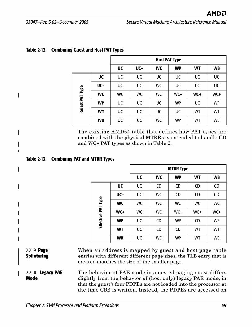
33047—Rev. 3.02—December 2005 Secure Virtual Machine Architecture Reference Manual
Chapter 2: SVM Processor and Platform Extensions 59
The existing AMD64 table that defines how PAT types arecombined with the physical MTRRs is extended to handle CDand WC+ PAT types as shown in Table 2.
2.21.9 Page Splintering
When an address is mapped by guest and host page tableentries with different different page sizes, the TLB entry that iscreated matches the size of the smaller page.
2.21.10 Legacy PAE Mode
The behavior of PAE mode in a nested-paging guest differsslightly from the behavior of (host-only) legacy PAE mode, inthat the guest’s four PDPEs are not loaded into the processor atthe time CR3 is written. Instead, the PDPEs are accessed on
Table 2-12. Combining Guest and Host PAT Types
Host PAT Type
UC UC– WC WP WT WB
Gues
t PAT
Typ
eUC UC UC UC UC UC UC
UC– UC UC WC UC UC UC
WC WC WC WC WC+ WC+ WC+
WP UC UC UC WP UC WP
WT UC UC UC UC WT WT
WB UC UC WC WP WT WB
Table 2-13. Combining PAT and MTRR Types
MTRR Type
UC WC WP WT WB
Effe
ctiv
e PA
T Ty
pe
UC UC CD CD CD CD
UC– UC WC CD CD CD
WC WC WC WC WC WC
WC+ WC WC WC+ WC+ WC+
WP UC CD WP CD WP
WT UC CD CD WT WT
WB UC WC WP WT WB
Secure Virtual Machine Architecture Reference Manual 33047—Rev. 3.02—December 2005
60 Chapter 2: SVM Processor and Platform Extensions
demand as part of a table walk. This has the side-effect thatillegal bit combinations in the PDPEs are not signaled at thetime that CR3 is written, but instead when the faulty PDPE isaccessed as part of a table walk.
This means that an operating system cannot rely on thebehavior when the in-memory PDPEs are different than the in-processor copy.
2.21.11 A20 Masking There is no provision for applying A20 masking to guestphysical addresses; the VMM can emulate A20 masking bychanging the host-level page mappings accordingly.
2.21.12 Detecting Nested Paging Support
Nested Paging is an optional feature of SVM and is notavailable in all implementations of SVM-capable processors.The CPUID instruction should be used to detect nested pagingsupport on a particular processor (see Appendix B on page 91for the details of processor feature identification and support).
33047—Rev. 3.02—December 2005 Secure Virtual Machine Architecture Reference Manual
Chapter 3: Security 61
3 Security
SVM provides additional hardware support that is designed tofacilitate the construction of trusted software systems. Whilethe security features described in this section are orthogonal toSVM’s virtualization support (and are not required forprocessor virtualization), the two form building blocks fortrusted systems.
SKINIT Instruction. The SKINIT instruction and associated systemsupport (the Trusted Platform Module or TPM) are designed toallow for verifiable startup of trusted software (such as aVMM), based on secure hash comparison.
Automatic Memory Clearing. Automatic clearing of memory uponreset protects secrets stored in system memory from simplereset-based attacks.
Security Exception. A new security exception (#SX) is used tosignal certain security-critical events.
3.1 Secure Startup with SKINIT
The SKINIT instruction is one of the keys to creating a “root oftrust” starting with an initially untrusted operating mode.SKINIT reinitializes the processor to establish a secureexecution environment for a software component called thesecure loader (SL) and starts execution of the SL in a way thatcannot be tampered with. SKINIT also copies the secure loaderexecutable image to an external device, such as a TrustedPlatform Module (TPM) for verification using unique bustransactions that preclude SKINIT operation from beingemulated by software in a way that the TPM could not readilydetect. (Detailed operation is described in Section 3.1.4.)
3.1.1 Secure Loader A secure loader (SL) typically initializes SVM hardwaremechanisms and related data structures, and initiatesexecution of a trusted piece of software such as a VMM or VMM(referred to as a Security Kernel, or SK, in this document), afterfirst having validated the identity of that software.
One of the main features of SKINIT allows SVM protections tobe reliably enabled after the system is already up and running
Secure Virtual Machine Architecture Reference Manual 33047—Rev. 3.02—December 2005
62 Chapter 3: Security
in a non-trusted mode — there is no requirement to change thetypical x86 platform boot process.
Exact details of the handoff from the SL to an SK aredependent on characteristics of the SL, SK and the initialuntrusted operating environment. However, there are specificrequirements for the SL image, as described in Section 3.1.2.
3.1.2 Secure Loader Image
The secure loader (SL) image contains all code and initializeddata sections of a secure loader. This code and initial data areused to initialize and start a security kernel in a completely safemanner, including setting up DEV protection for memoryallocated for use by SL and SK. The SL image is loaded into aregion of memory called the secure loader block (SLB) and canbe no larger than 64Kbyte (see “Secure Loader Block” onpage 62). The SL image is defined to start at byte offset 0 in theSLB.
The first word (16 bits) of the SL image must specify the SLentry point as an unsigned offset into the SL image. The secondword must contain the length of the image in bytes; themaximum length allowed is 65535 bytes. These two values areused by the SKINIT instruction. The layout of the rest of theimage is determined by software conventions. The imagetypically includes a digital signature for validation purposes.The digital signature hash must include the entry point andlength fields. SKINIT transfers the SL image to the TPM forvalidation prior to starting SL execution (see “SKINITOperation” on page 65 for further details of this transfer). TheSL image for which the hash is computed must be ready toexecute without prior manipulation.
3.1.3 Secure Loader Block
The secure loader block is a 64Kbyte range of physical memorywhich may be located at any 64Kbyte-aligned address below4Gbyte. The SL image must have been loaded into the SLBstarting at offset 0 before executing SKINIT. The physicaladdress of the SLB is provided as an input operand (in the EAXregister) to SKINIT, which sets up special protection for the SLBagainst device accesses (i.e., the DEV need not be activatedyet).
The SL must be written to execute initially in flat 32-bitprotected mode with paging disabled. A base address can bederived from the value in EAX to access data areas within the
33047—Rev. 3.02—December 2005 Secure Virtual Machine Architecture Reference Manual
Chapter 3: Security 63
SL image using base+displacement addressing, to make the SLcode position-independent.
Memory between the end of the SL image and the end of theSLB may be used immediately upon entry by the SL as securescratch space, such as for an initial stack, before DEVprotections are set up for the rest of memory. The amount ofspace required for this will limit the maximum size of the SLimage, and will depend on SL implementation. SKINIT sets theESP register to the appropriate top-of-stack value (EAX +10000h).
Figure 3-1 illustrates the layout of the SLB, showing where EAXand ESP point after SKINIT execution. Labels in italicsindicate suggested uses; other labels reflect required items.
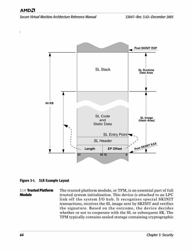
Secure Virtual Machine Architecture Reference Manual 33047—Rev. 3.02—December 2005
64 Chapter 3: Security
t
Figure 3-1. SLB Example Layout
3.1.4 Trusted Platform Module
The trusted platform module, or TPM, is an essential part of fulltrusted system initialization. This device is attached to an LPClink off the system I/O hub. It recognizes special SKINITtransactions, receives the SL image sent by SKINIT and verifiesthe signature. Based on the outcome, the device decideswhether or not to cooperate with the SL or subsequent SK. TheTPM typically contains sealed storage containing cryptographic
SL Stack
SL Codeand
Static Data
SL Entry Point
SL Header
Length EP Offset
31 16 15 0
64 KB
SL RuntimeData Area
SL Image(Hash Area)
Post SKINIT ESP
Post SKINIT EAX
33047—Rev. 3.02—December 2005 Secure Virtual Machine Architecture Reference Manual
Chapter 3: Security 65
keys and other high-security information that may be specific tothe platform.
3.1.5 System Interface, Memory Controller and I/O Hub Logic
SKINIT uses special support logic in the processor’s systeminterface unit, the internal controller and the I/O hub to whichthe TPM is attached. SKINIT uses special transactions that areunique to SKINIT, along with this support logic, designed tosecurely transmit the SL Image to the TPM for validation.
The use of this special protocol should allow the TPM to reliablydetect true execution, as opposed to emulation, of a trustedSecure Loader, which in turn provides a reliable means forverifying the subsequent loading and startup of a trustedSecurity Kernel.
3.1.6 SKINIT Operation
The SKINIT instruction is intended to be used primarily innormal mode prior to the VMM taking control.
SKINIT takes the physical base address of the SLB as its onlyinput operand in EAX, and performs the following steps:
1. Reinitialize processor state in the same manner as for theINIT signal, then enter flat 32-bit protected mode withpaging off. The CS and SS selectors are set to 0008h and0010h respectively, and CS and SS base, limit and attributeregisters are set to (base = 0, limit = 4G, CS:read-only,SS:read/write, expand-up). DS, ES, FS and GS are left as 16-bit real mode segments and the SL must reload these withprotected mode selectors having appropriate GDT entriesbefore using them. (Initialized data in the SLB may bereferenced using the SS segment override prefix until DS isreloaded.) The general purpose registers are cleared exceptfor EAX, which points to the start of the secure loader,EDX, which contains model, family and steppinginformation, and ESP, which contains the initial stackpointer for the secure loader. Cache contents remain intact,as do the x87 and SSE control registers. Most MSRs alsoretain their values, except those which might compromiseSVM protections. The EFER MSR, however, is cleared. TheDPD, R_INIT and DIS_A20M flags in the VM_CR registerare unconditionally set to 1.
Secure Virtual Machine Architecture Reference Manual 33047—Rev. 3.02—December 2005
66 Chapter 3: Security
2. Form the SLB base address by clearing bits 15–0 of EAX(EAX is updated), and enable the SL_DEV protectionmechanism (see “Secure Initialization Support” on page 51)to protect the 64-Kbyte region of physical memory startingat the SLB base address from any device access.
3. In multiprocessor operation, perform an inter-processorhandshake as described in Section 3.1.8 on page 67.
4. Read the SL image from memory and transmit it to the TPMin a manner that cannot be emulated by software.
5. Signal the TPM to complete the hash and verify thesignature. If any failures have occurred along the way, theTPM will conclude that no valid SL was started.
6. Clear the Global Interrupt Flag. This disables all interrupts,including NMI, SMI and INIT and ensures that thesubsequent code can execute atomically. If the processorenters the shutdown state (due to a triple fault for instance)while GIF is clear, it can only be restarted by means of aRESET.
7. Update the ESP register to point to the first byte beyondthe end of the SLB (SLB base + 65536), so that the first itempushed onto the stack by the SL will be at the top of theSLB.
8. Add the unsigned 16-bit entry point offset value from theSLB to the SLB base address to form the SL entry pointaddress, and jump to it.
The validation of the SL image by the TPM is a one-waytransaction as far as SKINIT is concerned. It does not depend onany response from the TPM after transferring the SL imagebefore jumping to the SL entry point, and initiates execution ofthe Secure Loader unconditionally. Because of the processorinitialization performed, SKINIT does not honor instruction ordata breakpoint traps, or trace traps due to EFLAGS.TF.
Pending interrupts. Device interrupts that may be pending prior toSKINIT execution due to EFLAGS.IF being clear, or that assertduring the execution of SKINIT, will be held pending untilsoftware subsequently sets GIF to 1. Similarly, SMI, INIT andNMI interrupts that assert after the start of SKINIT executionwill also be held pending until GIF is set to 1.
33047—Rev. 3.02—December 2005 Secure Virtual Machine Architecture Reference Manual
Chapter 3: Security 67
Debug considerations. SKINIT automatically disables variousimplementation-specific hardware debug features such as HDTthat could subvert security. A debug version of the SL canreenable those features by clearing the VM_CR.DPD flagimmediately upon entry.
3.1.7 SL Abort If the SL determines that it cannot properly initialize a validSK, it must cause GIF to be set to 1 and clear the VM_CR MSRto re-enable normal processor operation.
3.1.8 Secure Multiprocessor Initialization
The following standard APIC features are used for secure MPinitialization:
The concept of a single Bootstrap Processor (BSP) andmultiple Application Processors (APs).
The INIT inter-processor interrupt (IPI), which puts thetarget processors into a halted state which is responsive onlyto a subsequent Startup IPI.
The Startup IPI causes target processors to begin executionat a location in memory that is specified by the BootProcessor and conveyed along with the Startup IPI. Theoperation of the processor in response to a Startup IPI isslightly modified to support secure initialization, asdescribed below.
A Startup IPI normally causes an AP to start execution at alocation provided by the IPI. To support secure MP startup,each AP responds to a startup IPI by additionally clearing itsGIF and setting the DPD, R_INIT and DIS_A20M flags in theVM_CR register if, and only if, the BSP has indicated that it hasexecuted an SKINIT. All other aspects of Startup IPI behaviorremain unchanged.
Software requirements for Secure MP initialization. The dr iver thatstarts the SL must execute on the BSP. Prior to executing theSKINIT instruction, the driver must arrange for any processor-specific system register contents to be saved to memory (to berestored after the APs undergo hardware re-initialization), andfor all APs to be idled using whatever software means isappropriate (for example, by means of an OS kernel function ordriver threads running on the other processors). Once thedriver has confirmed that all APs are idle, it must issue an INITIPI to all APs and wait for its localAPIC Busy indication to clear.This places the APs into a halted state which is responsive onlyto a subsequent Startup IPI (although the APs will still respond
Secure Virtual Machine Architecture Reference Manual 33047—Rev. 3.02—December 2005
68 Chapter 3: Security
to snoops for cache coherency). The driver may execute SKINITany t ime af ter th is point . Depending on processorimplementation, a fixed delay of no more than 1000 processorcycles may be necessary before executing SKINIT to ensurereliable sensing of APIC INIT state by the SKINIT.
AP Startup Sequence. While the SL starts executing on the BSP, theAPs remain halted in APIC INIT state. Either the SL or the SKmay issue the Startup IPI for the APs at whatever point isdeemed appropriate. The Startup IPI conveys an 8-bit vectorspecified by the software that issues the IPI to the APs. Thisvector provides the upper 8 bits of a 20-bit physical address.Therefore, the AP startup code must reside in the lower 1Mbyteof physical memory—with the entry point at offset 0 on thatparticular page.
In response to the Startup IPI, the APs start executing at thespecified location in 16-bit real mode. This AP startup codemust set up protections on each processor as determined by theSL or SK. It must also set GIF to re-enable interrupts, andrestore the pre-SKINIT system context (as directed by the SL orSK executing on the BSP), before resuming normal systemoperation.
The SL must guarantee the integrity of the AP startupsequence, for example by including the startup code in thehashed SL image and setting up DEV protection for it beforecopying it to the desired area. The AP startup code does notneed to (and should not) execute SKINIT.
Pending interrupts. Device interrupts that may be pending on anAP prior to the APIC INIT IPI due to EFLAGS.IF being clear, orthat assert any time after the processor has accepted the INITIPI, will be held pending through the subsequent Startup IPI,and remain pending until software sets GIF to 1 on that AP.Similarly, SMI, INIT, and NMI interrupts that assert after theprocessor has accepted the INIT IPI will also be held pendinguntil GIF is set to 1.
Aborting MP initialization. In the event that the SL or SK on theBSP decides to abort SVM system initialization for any reason,the following clean-up actions must be performed by SL codeexecuting on each processor before returning control to theoriginal operating environment:
33047—Rev. 3.02—December 2005 Secure Virtual Machine Architecture Reference Manual
Chapter 3: Security 69
The BSP and all APs that responded to the Startup IPI mustrestore GIF and clear VM_CR on each processor for normaloperation.
For each processor that has a distinct memory controllerassociated with it, the SL_DEV_EN flag in the DEV controlregister must be cleared in order to restore normal deviceaccessibility to the 64KB SL memory range.
Any secure context created by the SL that should not beexposed to untrusted code should be cleaned up as appropriatebefore these steps are taken.
3.2 Automatic Memory Clear
Automatic memory clear (AMC) erases the contents of sytemmemory after the processor is subjected to a cold reset, andunder controlled circumstances after a warm reset.
The processor shadows the AMC Check registers (thenorthbridge registers that configure the DRAM size andconfiguration), for use after the next warm reset. The shadowcopies are updated each time the DRAM controller completesinitialization.
The memory clear operates as follows:
Memory is cleared after warm reset, when DRAM access isfirst enabled, if either of these conditions is true
- AMC was not disabled in the northbridge (MemClrDis =0), or
- the new value of the DRAM configuration registers donot match the shadowed AMC Check registers.
Once the memory clear starts, it continues throughcompletion (unless interrupted by a reset).
The range of DRAM cleared is the entire memory that wasenabled the previous time DRAM was enabled. Thisconfiguration can be determined from the shadow registers.
After the memory clear ends, the new AMC Check registervalues are shadowed, for use after the next warm reset.
After trusted software has taken steps to ensure that anysecrets in system memory have been removed or encrypted,trusted software is expected to set MemClrDis before enteringthe ACPI-defined S3 state (suspend to RAM).
Secure Virtual Machine Architecture Reference Manual 33047—Rev. 3.02—December 2005
70 Chapter 3: Security
Refer to the AMD BIOS and Kernel Developer's Guide for yourprocessor for details on the relevant register definitions.
3.3 Security Exception (#SX)
The Security Exception fault signals security-sensitive eventsthat occur while executing the VMM, in the form of anexception so that the VMM may take appropriate action. (AVMM would typically intercept comparable sensitive events inthe guest.) In the current implementation, the only use of the#SX is to redirect external INITs into an exception so that theVMM may — among other possibilities — destroy sensitiveinformation before re-issuing the INIT, this time withoutredirection. (The INIT redirection is controlled by theVM_CR.R_INIT bit.)
The #SX exception dispatches to vector 30, and behaves likeother fault-class exceptions such as General Protection Fault(#GP). The #SX exception pushes an error code. The only errorcode currently defined is 1, and indicates redirection of INIThas occurred.
The #SX exception is a contributory fault.
71
33047—Rev. 3.02—December 2005 Secure Virtual Machine Architecture Reference Manual
4 SVM Instruction Set Reference
AMD virtualization technology introduces several newinstructions and modifies several existing instructions tofacilitate the implementation of VMM systems.
The SVM instruction set includes instructions to:
Start execution of a guest (VMRUN)
Save and restore subsets of processor state (VMSAVE,VMLOAD)
Allow guests to explicitly communicate with the VMM(VMMCALL)
Set and clear the global interrupt flag (STGI, CLGI)
Invalidate TLB entries in a specified ASID (INVLPGA)
Read and write CR8 in all processor modes
Secure init and control transfer with attestation (SKINIT)
Enabling SVM also affects the behavior of existing AMD64instructions.
4.1 Changes to RSM Instruction
RSM is not allowed to change EFER.SVME. Attempts to do soare ignored.
When EFER.SVME is 1, RSM reloads the four PDPEs (throughthe incoming CR3) when returning to a mode that has legacyPAE mode paging enabled.
When EFER.SVME is 1, the RSM instruction is permitted toreturn to paged real mode (i.e., CR0.PE=0 and CR0.PG=1).
4.2 New Instructions
The basic operation of each SVM instruction is given in thepages that follow.

72 CLGI
Secure Virtual Machine Architecture Reference Manual 33047—Rev. 3.02—December 2005
Clears the global interrupt flag (GIF). While GIF is zero, all external interrupts aredisabled.
Related Instructions
STGI
rFLAGS Affected
None.
Exceptions
CLGI Clear Global Interrupt Flag
Mnemonic Opcode Description
CLGI 0F 01 DD Clears the global interupt flag (GIF).
Exception RealVirtual8086 Protected Cause of Exception
Invalid opcode, #UD
X X
X
X
The SVM instructions are not supported as indicated by ECX bit 2 as returned by CPUID extended function 8000_0001h.
EFER.SVME was zero.
This instruction is only recognized in protected mode.
General protection, #GP X CPL was not zero.
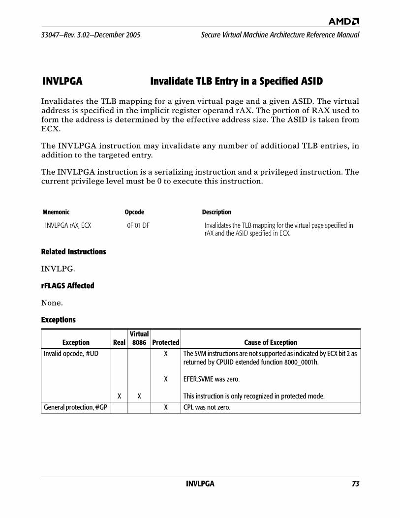
INVLPGA 73
33047—Rev. 3.02—December 2005 Secure Virtual Machine Architecture Reference Manual
Invalidates the TLB mapping for a given virtual page and a given ASID. The virtualaddress is specified in the implicit register operand rAX. The portion of RAX used toform the address is determined by the effective address size. The ASID is taken fromECX.
The INVLPGA instruction may invalidate any number of additional TLB entries, inaddition to the targeted entry.
The INVLPGA instruction is a serializing instruction and a privileged instruction. Thecurrent privilege level must be 0 to execute this instruction.
Related Instructions
INVLPG.
rFLAGS Affected
None.
Exceptions
INVLPGA Invalidate TLB Entry in a Specified ASID
Mnemonic Opcode Description
INVLPGA rAX, ECX 0F 01 DF Invalidates the TLB mapping for the virtual page specified in rAX and the ASID specified in ECX.
Exception RealVirtual8086 Protected Cause of Exception
Invalid opcode, #UD
X X
X
X
The SVM instructions are not supported as indicated by ECX bit 2 as returned by CPUID extended function 8000_0001h.
EFER.SVME was zero.
This instruction is only recognized in protected mode.
General protection, #GP X CPL was not zero.
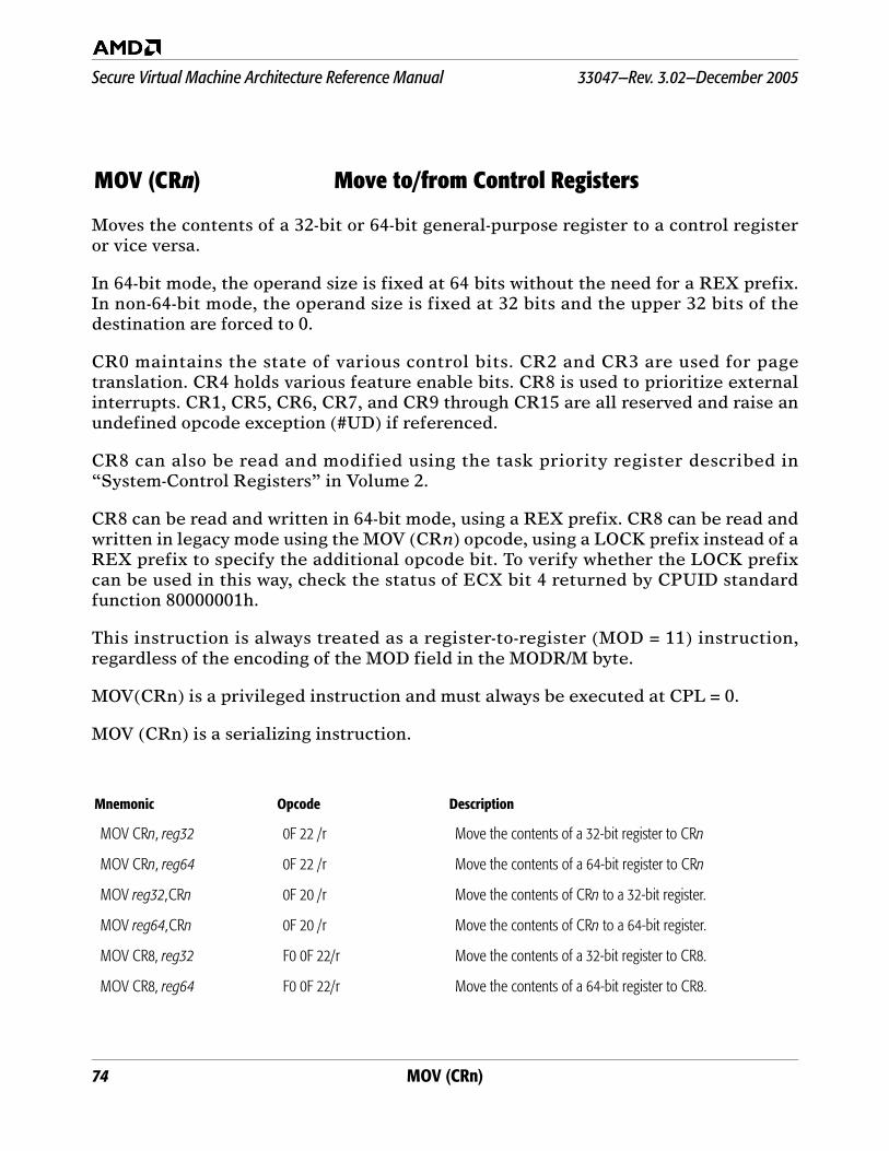
74 MOV (CRn)
Secure Virtual Machine Architecture Reference Manual 33047—Rev. 3.02—December 2005
Moves the contents of a 32-bit or 64-bit general-purpose register to a control registeror vice versa.
In 64-bit mode, the operand size is fixed at 64 bits without the need for a REX prefix.In non-64-bit mode, the operand size is fixed at 32 bits and the upper 32 bits of thedestination are forced to 0.
CR0 maintains the state of various control bits. CR2 and CR3 are used for pagetranslation. CR4 holds various feature enable bits. CR8 is used to prioritize externalinterrupts. CR1, CR5, CR6, CR7, and CR9 through CR15 are all reserved and raise anundefined opcode exception (#UD) if referenced.
CR8 can also be read and modified using the task priority register described in“System-Control Registers” in Volume 2.
CR8 can be read and written in 64-bit mode, using a REX prefix. CR8 can be read andwritten in legacy mode using the MOV (CRn) opcode, using a LOCK prefix instead of aREX prefix to specify the additional opcode bit. To verify whether the LOCK prefixcan be used in this way, check the status of ECX bit 4 returned by CPUID standardfunction 80000001h.
This instruction is always treated as a register-to-register (MOD = 11) instruction,regardless of the encoding of the MOD field in the MODR/M byte.
MOV(CRn) is a privileged instruction and must always be executed at CPL = 0.
MOV (CRn) is a serializing instruction.
MOV (CRn) Move to/from Control Registers
Mnemonic Opcode Description
MOV CRn, reg32 0F 22 /r Move the contents of a 32-bit register to CRn
MOV CRn, reg64 0F 22 /r Move the contents of a 64-bit register to CRn
MOV reg32,CRn 0F 20 /r Move the contents of CRn to a 32-bit register.
MOV reg64,CRn 0F 20 /r Move the contents of CRn to a 64-bit register.
MOV CR8, reg32 F0 0F 22/r Move the contents of a 32-bit register to CR8.
MOV CR8, reg64 F0 0F 22/r Move the contents of a 64-bit register to CR8.
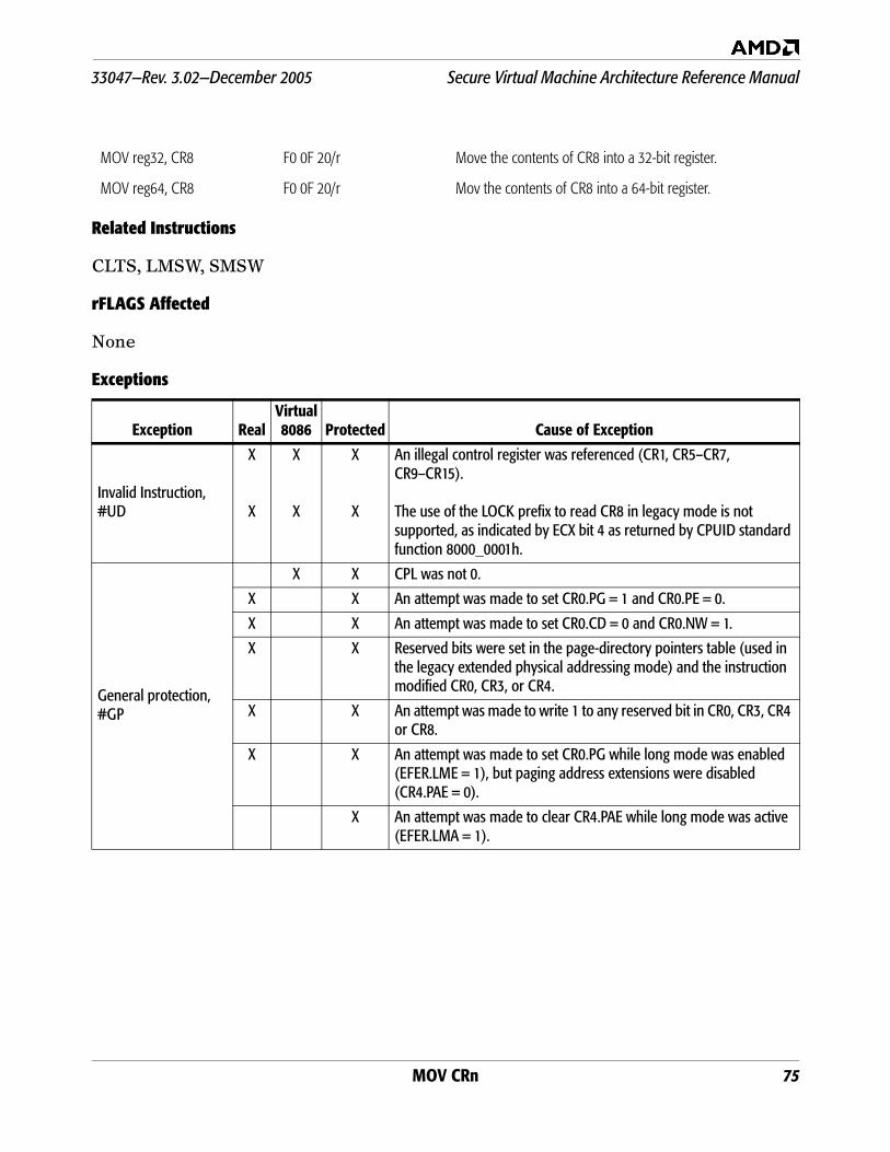
MOV CRn 75
33047—Rev. 3.02—December 2005 Secure Virtual Machine Architecture Reference Manual
Related Instructions
CLTS, LMSW, SMSW
rFLAGS Affected
None
Exceptions
MOV reg32, CR8 F0 0F 20/r Move the contents of CR8 into a 32-bit register.
MOV reg64, CR8 F0 0F 20/r Mov the contents of CR8 into a 64-bit register.
Exception RealVirtual8086 Protected Cause of Exception
Invalid Instruction, #UD
X
X
X
X
X
X
An illegal control register was referenced (CR1, CR5–CR7, CR9–CR15).
The use of the LOCK prefix to read CR8 in legacy mode is not supported, as indicated by ECX bit 4 as returned by CPUID standard function 8000_0001h.
General protection, #GP
X X CPL was not 0.
X X An attempt was made to set CR0.PG = 1 and CR0.PE = 0.
X X An attempt was made to set CR0.CD = 0 and CR0.NW = 1.
X X Reserved bits were set in the page-directory pointers table (used in the legacy extended physical addressing mode) and the instruction modified CR0, CR3, or CR4.
X X An attempt was made to write 1 to any reserved bit in CR0, CR3, CR4 or CR8.
X X An attempt was made to set CR0.PG while long mode was enabled (EFER.LME = 1), but paging address extensions were disabled (CR4.PAE = 0).
X An attempt was made to clear CR4.PAE while long mode was active (EFER.LMA = 1).
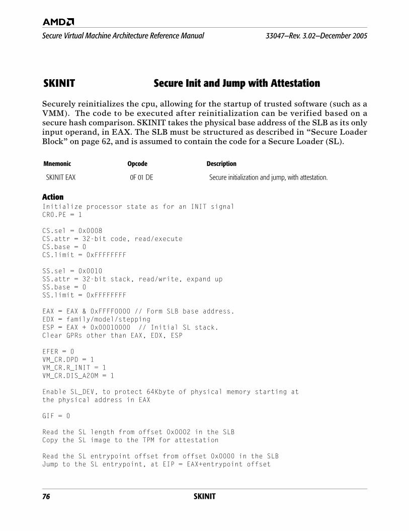
76 SKINIT
Secure Virtual Machine Architecture Reference Manual 33047—Rev. 3.02—December 2005
Securely reinitializes the cpu, allowing for the startup of trusted software (such as aVMM). The code to be executed after reinitialization can be verified based on asecure hash comparison. SKINIT takes the physical base address of the SLB as its onlyinput operand, in EAX. The SLB must be structured as described in “Secure LoaderBlock” on page 62, and is assumed to contain the code for a Secure Loader (SL).
ActionInitialize processor state as for an INIT signalCR0.PE = 1
CS.sel = 0x0008CS.attr = 32-bit code, read/executeCS.base = 0CS.limit = 0xFFFFFFFF
SS.sel = 0x0010SS.attr = 32-bit stack, read/write, expand upSS.base = 0SS.limit = 0xFFFFFFFF
EAX = EAX & 0xFFFF0000 // Form SLB base address.EDX = family/model/steppingESP = EAX + 0x00010000 // Initial SL stack.Clear GPRs other than EAX, EDX, ESP
EFER = 0VM_CR.DPD = 1VM_CR.R_INIT = 1VM_CR.DIS_A20M = 1
Enable SL_DEV, to protect 64Kbyte of physical memory starting at the physical address in EAX
GIF = 0
Read the SL length from offset 0x0002 in the SLBCopy the SL image to the TPM for attestation
Read the SL entrypoint offset from offset 0x0000 in the SLBJump to the SL entrypoint, at EIP = EAX+entrypoint offset
SKINIT Secure Init and Jump with Attestation
Mnemonic Opcode Description
SKINIT EAX 0F 01 DE Secure initialization and jump, with attestation.

SKINIT 77
33047—Rev. 3.02—December 2005 Secure Virtual Machine Architecture Reference Manual
Related Instructions
None.
rFLAGS Affected
Exceptions
ID VIP VIF AC VM RF NT IOPL OF DF IF TF SF ZF AF PF CF
0 0 0 0 0 0 0 0 0 0 0 0 0 0 0 0 0
21 20 19 18 17 16 14 13–12 11 10 9 8 7 6 4 2 0
Note: Bits 31–22, 15, 5, 3, and 1 are reserved. A flag set to 1 or cleared to 0 is M (modified). Unaffected flags are blank. Undefinedflags are U.
Exception RealVirtual8086 Protected Cause of Exception
Invalid opcode, #UD
X X
X
X
The SVM instructions are not supported as indicated by ECX bit 2 as returned by CPUID extended function 8000_0001h.
EFER.SVME was zero.
This instruction is only recognized in protected mode.
General protection, #GP X CPL was not zero.
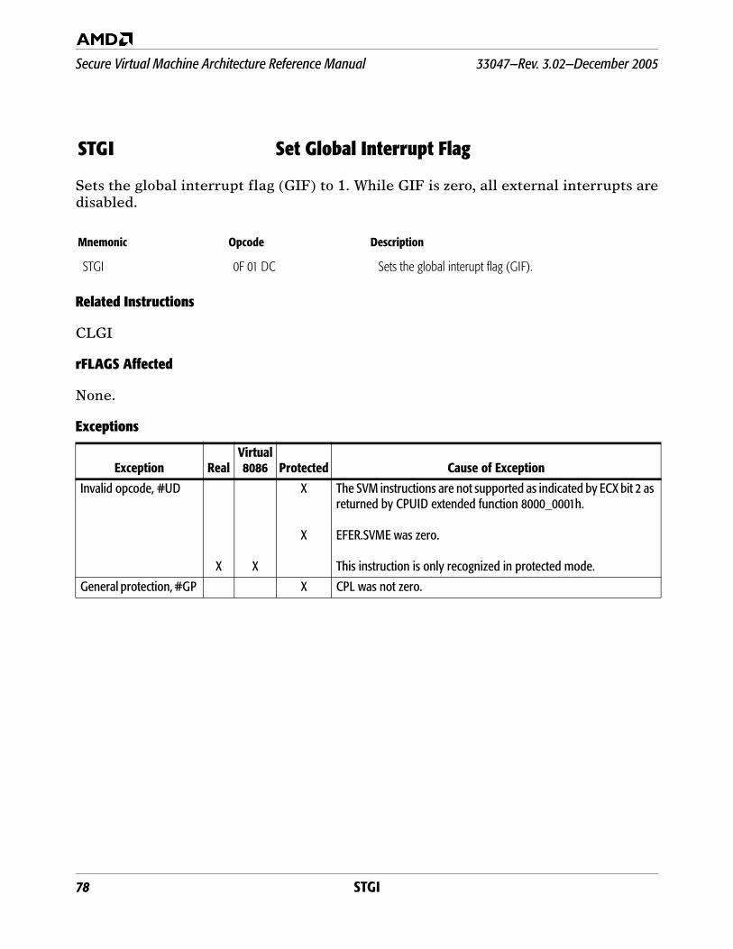
78 STGI
Secure Virtual Machine Architecture Reference Manual 33047—Rev. 3.02—December 2005
Sets the global interrupt flag (GIF) to 1. While GIF is zero, all external interrupts aredisabled.
Related Instructions
CLGI
rFLAGS Affected
None.
Exceptions
STGI Set Global Interrupt Flag
Mnemonic Opcode Description
STGI 0F 01 DC Sets the global interupt flag (GIF).
Exception RealVirtual8086 Protected Cause of Exception
Invalid opcode, #UD
X X
X
X
The SVM instructions are not supported as indicated by ECX bit 2 as returned by CPUID extended function 8000_0001h.
EFER.SVME was zero.
This instruction is only recognized in protected mode.
General protection, #GP X CPL was not zero.

VMLOAD 79
33047—Rev. 3.02—December 2005 Secure Virtual Machine Architecture Reference Manual
Loads a subset of processor state from the VMCB specified by the physical address inthe rAX register. The portion of RAX used to form the address is determined by theeffective address size.
The VMSAVE and VMLOAD instructions complement the state save/restore abilitiesof VMRUN and #VMEXIT, providing access to hidden state that software is otherwiseunable to access, plus some additional commonly-used state.
ActionLoad from a VMCB at physical address rAX:
FS, GS, TR, LDTR (including all hidden state)KernelGsBaseSTAR, LSTAR, CSTAR, SFMASKSYSENTER_CS, SYSENTER_ESP, SYSENTER_EIP
Related Instructions
VMSAVE
rFLAGS Affected
None.
Exceptions
VMLOAD Load State from VMCB
Mnemonic Opcode Description
VMLOAD rAX 0F 01 DA Load additional state from VMCB.
Exception RealVirtual8086 Protected Cause of Exception
Invalid opcode, #UD
X X
X
X
The SVM instructions are not supported as indicated by ECX bit 2 as returned by CPUID extended function 8000_0001h.
EFER.SVME was zero.
This instruction is only recognized in protected mode.
General protection, #GP X
X
X
CPL was not zero.
rAX referenced a physical address above the maximum supported physical address.
The address in rAX was not aligned on a 4Kbyte boundary.
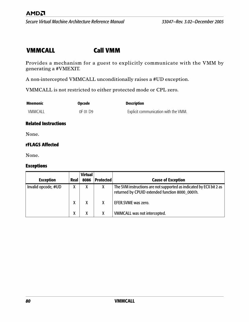
80 VMMCALL
Secure Virtual Machine Architecture Reference Manual 33047—Rev. 3.02—December 2005
Provides a mechanism for a guest to explicitly communicate with the VMM bygenerating a #VMEXIT.
A non-intercepted VMMCALL unconditionally raises a #UD exception.
VMMCALL is not restricted to either protected mode or CPL zero.
Related Instructions
None.
rFLAGS Affected
None.
Exceptions
VMMCALL Call VMM
Mnemonic Opcode Description
VMMCALL 0F 01 D9 Explicit communication with the VMM.
Exception RealVirtual8086 Protected Cause of Exception
Invalid opcode, #UD X
X
X
X
X
X
X
X
X
The SVM instructions are not supported as indicated by ECX bit 2 as returned by CPUID extended function 8000_0001h.
EFER.SVME was zero.
VMMCALL was not intercepted.
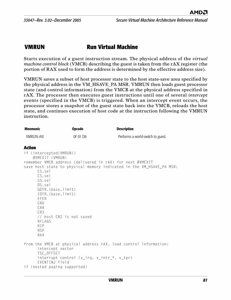
VMRUN 81
33047—Rev. 3.02—December 2005 Secure Virtual Machine Architecture Reference Manual
Starts execution of a guest instruction stream. The physical address of the virtualmachine control block (VMCB) describing the guest is taken from the rAX register (theportion of RAX used to form the address is determined by the effective address size).
VMRUN saves a subset of host processor state to the host state-save area specified bythe physical address in the VM_HSAVE_PA MSR. VMRUN then loads guest processorstate (and control information) from the VMCB at the physical address specified inrAX. The processor then executes guest instructions until one of several interceptevents (specified in the VMCB) is triggered. When an intercept event occurs, theprocessor stores a snapshot of the guest state back into the VMCB, reloads the hoststate, and continues execution of host code at the instruction following the VMRUNinstruction.
Actionif (intercepted(VMRUN)) #VMEXIT (VMRUN)remember VMCB address (delivered in rAX) for next #VMEXITsave host state to physical memory indicated in the VM_HSAVE_PA MSR:
ES.selCS.selSS.selDS.selGDTR.{base,limit}IDTR.{base,limit}EFERCR0CR4CR3// host CR2 is not savedRFLAGSRIPRSPRAX
from the VMCB at physical address rAX, load control information:intercept vectorTSC_OFFSETinterrupt control (v_irq, v_intr_*, v_tpr)EVENTINJ field
if (nested paging supported)
VMRUN Run Virtual Machine
Mnemonic Opcode Description
VMRUN rAX 0F 01 D8 Performs a world-switch to guest.
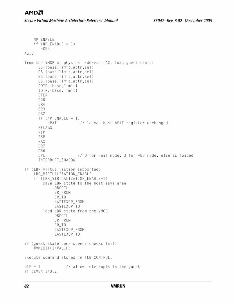
82 VMRUN
Secure Virtual Machine Architecture Reference Manual 33047—Rev. 3.02—December 2005
NP_ENABLE if (NP_ENABLE = 1)
hCR3ASID
from the VMCB at physical address rAX, load guest state:ES.{base,limit,attr,sel}CS.{base,limit,attr,sel}SS.{base,limit,attr,sel}DS.{base,limit,attr,sel}GDTR.{base,limit}IDTR.{base,limit}EFERCR0CR4CR3CR2if (NP_ENABLE = 1) gPAT // leaves host hPAT register unchangedRFLAGSRIPRSPRAXDR7DR6CPL // 0 for real mode, 3 for v86 mode, else as loadedINTERRUPT_SHADOW
if (LBR virtualization supported) LBR_VIRTUALIZATION_ENABLE if (LBR_VIRTUALIZATION_ENABLE=1) save LBR state to the host save area DBGCTL BR_FROM BR_TO LASTEXCP_FROM LASTEXCP_TO load LBR state from the VMCB DBGCTL BR_FROM BR_TO LASTEXCP_FROM LASTEXCP_TO
if (guest state consistency checks fail) #VMEXIT(INVALID)
Execute command stored in TLB_CONTROL.
GIF = 1 // allow interrupts in the guestif (EVENTINJ.V)
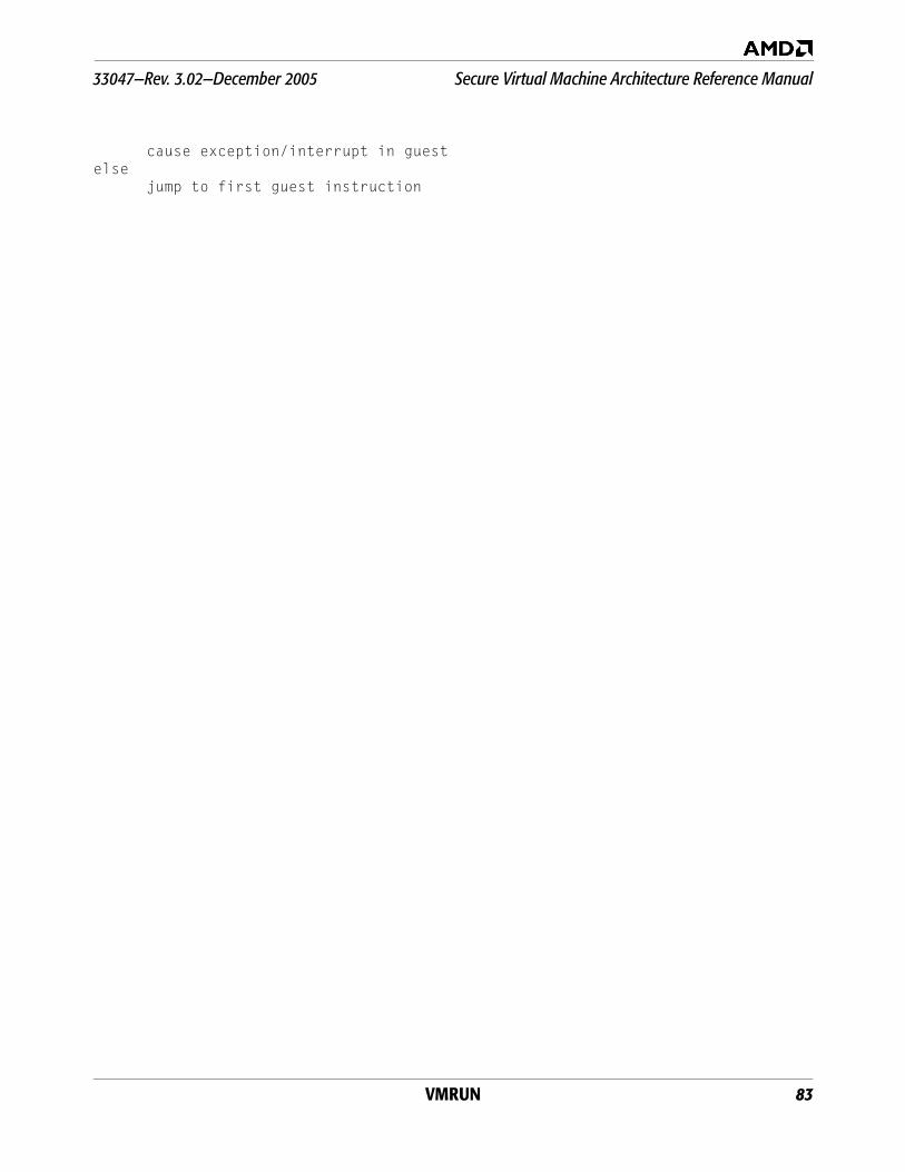
VMRUN 83
33047—Rev. 3.02—December 2005 Secure Virtual Machine Architecture Reference Manual
cause exception/interrupt in guestelse
jump to first guest instruction
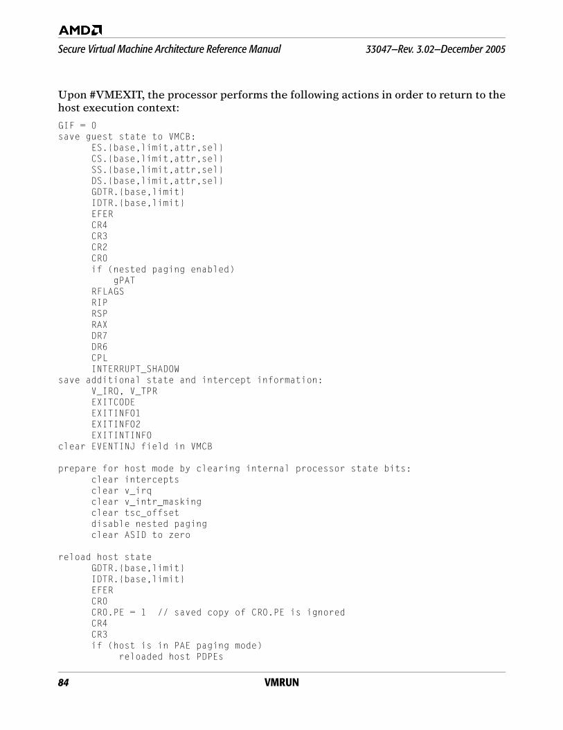
84 VMRUN
Secure Virtual Machine Architecture Reference Manual 33047—Rev. 3.02—December 2005
Upon #VMEXIT, the processor performs the following actions in order to return to thehost execution context:
GIF = 0save guest state to VMCB:
ES.{base,limit,attr,sel}CS.{base,limit,attr,sel}SS.{base,limit,attr,sel}DS.{base,limit,attr,sel}GDTR.{base,limit}IDTR.{base,limit}EFERCR4CR3CR2CR0if (nested paging enabled) gPATRFLAGSRIPRSPRAXDR7DR6CPLINTERRUPT_SHADOW
save additional state and intercept information:V_IRQ, V_TPREXITCODEEXITINFO1EXITINFO2EXITINTINFO
clear EVENTINJ field in VMCB
prepare for host mode by clearing internal processor state bits:clear interceptsclear v_irqclear v_intr_maskingclear tsc_offsetdisable nested paging clear ASID to zero
reload host state GDTR.{base,limit}IDTR.{base,limit}EFERCR0CR0.PE = 1 // saved copy of CR0.PE is ignoredCR4CR3if (host is in PAE paging mode)
reloaded host PDPEs
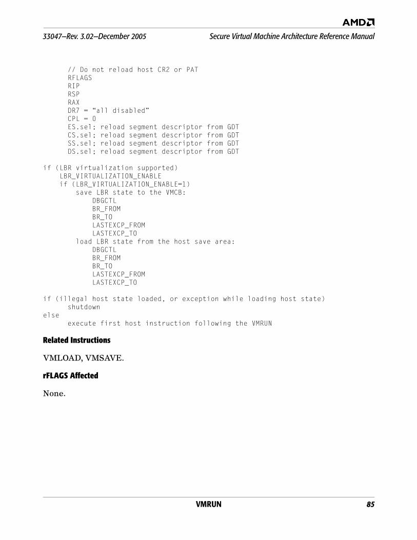
VMRUN 85
33047—Rev. 3.02—December 2005 Secure Virtual Machine Architecture Reference Manual
// Do not reload host CR2 or PATRFLAGSRIPRSPRAXDR7 = “all disabled”CPL = 0ES.sel; reload segment descriptor from GDTCS.sel; reload segment descriptor from GDTSS.sel; reload segment descriptor from GDTDS.sel; reload segment descriptor from GDT
if (LBR virtualization supported) LBR_VIRTUALIZATION_ENABLE if (LBR_VIRTUALIZATION_ENABLE=1) save LBR state to the VMCB: DBGCTL BR_FROM BR_TO LASTEXCP_FROM LASTEXCP_TO load LBR state from the host save area: DBGCTL BR_FROM BR_TO LASTEXCP_FROM LASTEXCP_TO
if (illegal host state loaded, or exception while loading host state)shutdown
elseexecute first host instruction following the VMRUN
Related Instructions
VMLOAD, VMSAVE.
rFLAGS Affected
None.
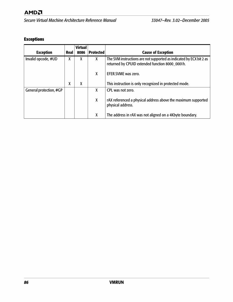
86 VMRUN
Secure Virtual Machine Architecture Reference Manual 33047—Rev. 3.02—December 2005
Exceptions
Exception RealVirtual8086 Protected Cause of Exception
Invalid opcode, #UD X
X
X
X
X
X
The SVM instructions are not supported as indicated by ECX bit 2 as returned by CPUID extended function 8000_0001h.
EFER.SVME was zero.
This instruction is only recognized in protected mode.
General protection, #GP X
X
X
CPL was not zero.
rAX referenced a physical address above the maximum supported physical address.
The address in rAX was not aligned on a 4Kbyte boundary.
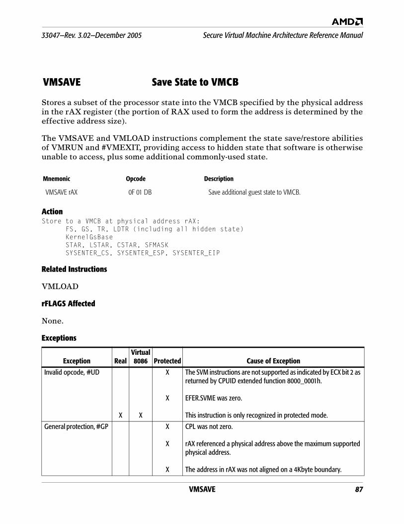
VMSAVE 87
33047—Rev. 3.02—December 2005 Secure Virtual Machine Architecture Reference Manual
Stores a subset of the processor state into the VMCB specified by the physical addressin the rAX register (the portion of RAX used to form the address is determined by theeffective address size).
The VMSAVE and VMLOAD instructions complement the state save/restore abilitiesof VMRUN and #VMEXIT, providing access to hidden state that software is otherwiseunable to access, plus some additional commonly-used state.
ActionStore to a VMCB at physical address rAX:
FS, GS, TR, LDTR (including all hidden state)KernelGsBaseSTAR, LSTAR, CSTAR, SFMASKSYSENTER_CS, SYSENTER_ESP, SYSENTER_EIP
Related Instructions
VMLOAD
rFLAGS Affected
None.
Exceptions
VMSAVE Save State to VMCB
Mnemonic Opcode Description
VMSAVE rAX 0F 01 DB Save additional guest state to VMCB.
Exception RealVirtual8086 Protected Cause of Exception
Invalid opcode, #UD
X X
X
X
The SVM instructions are not supported as indicated by ECX bit 2 as returned by CPUID extended function 8000_0001h.
EFER.SVME was zero.
This instruction is only recognized in protected mode.
General protection, #GP X
X
X
CPL was not zero.
rAX referenced a physical address above the maximum supported physical address.
The address in rAX was not aligned on a 4Kbyte boundary.
88 VMSAVE
Secure Virtual Machine Architecture Reference Manual 33047—Rev. 3.02—December 2005
33047—Rev. 3.02—December 2005 Secure Virtual Machine Architecture Reference Manual
Appendix A: Reset Values and INIT 89
Appendix A Reset Values and INIT
This appendix provides data on reset values of SVM-relateddata structures and features, and the reinitialization of state asa result of INIT.
A.1 Reset Values
The SVM-related processor state resets as follows:
EFER.SVME is cleared to 0 (SVM extensions disabled).
GIF is set to 1 (interrupts enabled globally).
SVM intercepts are cleared to 0 (no intercepts active).
The “current ASID” register is cleared to 0.
VM_CR is cleared to 0 (debug, INIT and A20M function asusual).
V_IRQ and V_INTR_MASKING are cleared to 0 (no virtualinterrupt pending, interrupt masking not virtualized).
TSC_OFFSET is cleared to 0 (RDTSC delivers “raw” value).
Nested paging is disabled.
SVM-related Northbridge state resets as follows:
DEV table features are disabled.
Interrupt Enable Register (IER) is set to “all vectorsenabled”.
A.2 Action of INIT
INIT can be intercepted when inside a guest (in which case itcauses a #VMEXIT and INIT is held pending) and can beredirected inside the host context, in which case it causes INITto be dropped and raises an #SX exception. In either case, theINIT has no effect on hardware state. Only if the INIT is neitherintercepted nor redirected does it reinitialize state as follows:
EFER.SVME is cleared to 0 (SVM extensions disabled).
GIF is set to 1 (interrupts enabled globally).
SVM intercepts are cleared to 0 (no intercepts active).
The “current ASID” register is cleared to 0.
Secure Virtual Machine Architecture Reference Manual 33047—Rev. 3.02—December 2005
90 Appendix A: Reset Values and INIT
VM_CR is cleared to 0 (debug, INIT and A20M function asusual).
V_IRQ and V_INTR_MASKING are cleared to 0 (no virtualinterrupt pending, interrupt masking not virtualized).
TSC_OFFSET is cleared to 0 (RDTSC delivers “raw” value).
Nested paging is disabled.
SVM-related Northbridge state is initialized as follows:
DEV table features are disabled.
Interrupt Enable Register (IER) is set to “all vectorsenabled”.
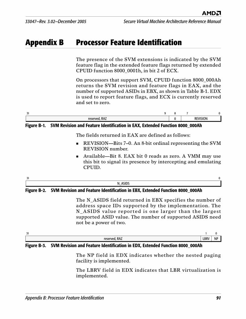
33047—Rev. 3.02—December 2005 Secure Virtual Machine Architecture Reference Manual
Appendix B: Processor Feature Identification 91
Appendix B Processor Feature Identification
The presence of the SVM extensions is indicated by the SVMfeature flag in the extended feature flags returned by extendedCPUID function 8000_0001h, in bit 2 of ECX.
On processors that support SVM, CPUID function 8000_000Ahreturns the SVM revision and feature flags in EAX, and thenumber of supported ASIDs in EBX, as shown in Table B-1. EDXis used to report feature flags, and ECX is currently reservedand set to zero.
The fields returned in EAX are defined as follows:
REVISION—Bits 7–0. An 8-bit ordinal representing the SVMREVISION number.
Available—Bit 8. EAX bit 0 reads as zero. A VMM may usethis bit to signal its presence by intercepting and emulatingCPUID.
The N_ASIDS field returned in EBX specifies the number ofaddress space IDs supported by the implementation. TheN_ASIDS value reported is one larger than the largestsupported ASID value. The number of supported ASIDS neednot be a power of two.
The NP field in EDX indicates whether the nested pagingfacility is implemented.
The LBRV field in EDX indicates that LBR virtualization isimplemented.
31 9 8 7 0
reserved, RAZ 0 REVISION
Figure B-1. SVM Revision and Feature Identification in EAX, Extended Function 8000_000Ah
31 0
N_ASIDS
Figure B-2. SVM Revision and Feature Identification in EBX, Extended Function 8000_000Ah
31 1 0
reserved, RAZ LBRV NP
Figure B-3. SVM Revision and Feature Identification in EDX, Extended Function 8000_000Ah
Secure Virtual Machine Architecture Reference Manual 33047—Rev. 3.02—December 2005
92 Appendix B: Processor Feature Identification
Future SVM features will be identified by a combination ofrevision number and feature flags in the currently reservedbits.
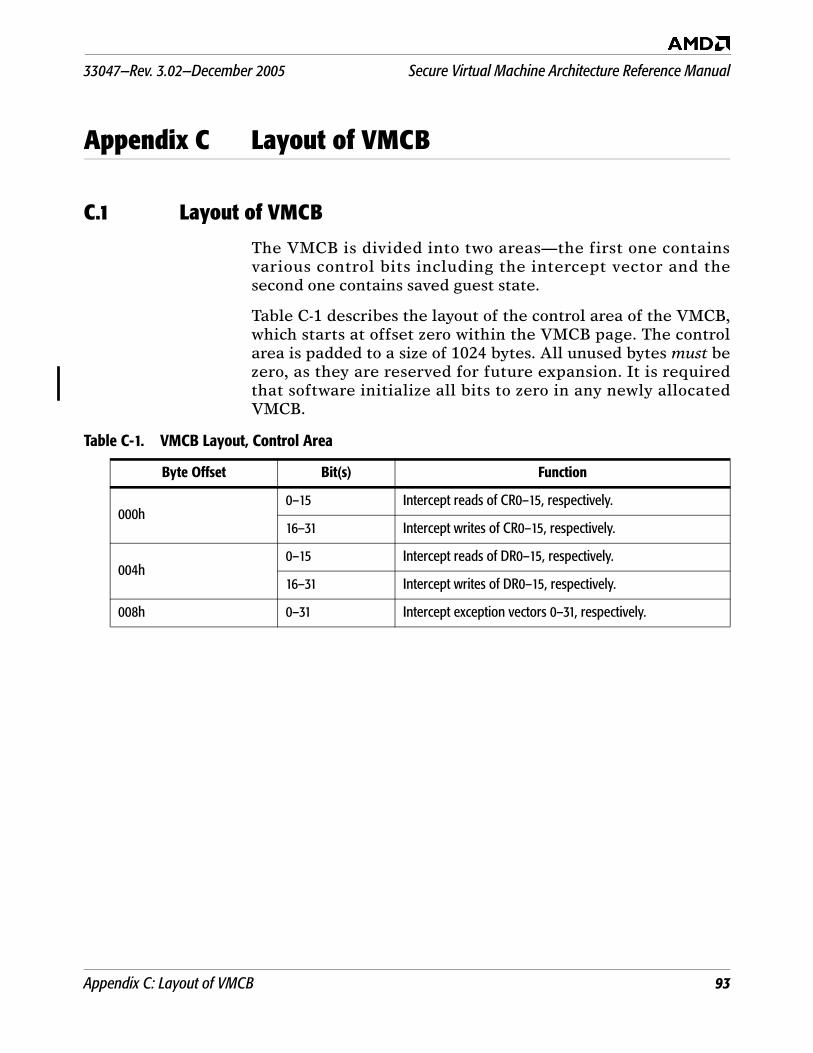
33047—Rev. 3.02—December 2005 Secure Virtual Machine Architecture Reference Manual
Appendix C: Layout of VMCB 93
Appendix C Layout of VMCB
C.1 Layout of VMCB
The VMCB is divided into two areas—the first one containsvarious control bits including the intercept vector and thesecond one contains saved guest state.
Table C-1 describes the layout of the control area of the VMCB,which starts at offset zero within the VMCB page. The controlarea is padded to a size of 1024 bytes. All unused bytes must bezero, as they are reserved for future expansion. It is requiredthat software initialize all bits to zero in any newly allocatedVMCB.
Table C-1. VMCB Layout, Control Area
Byte Offset Bit(s) Function
000h0–15 Intercept reads of CR0–15, respectively.
16–31 Intercept writes of CR0–15, respectively.
004h0–15 Intercept reads of DR0–15, respectively.
16–31 Intercept writes of DR0–15, respectively.
008h 0–31 Intercept exception vectors 0–31, respectively.
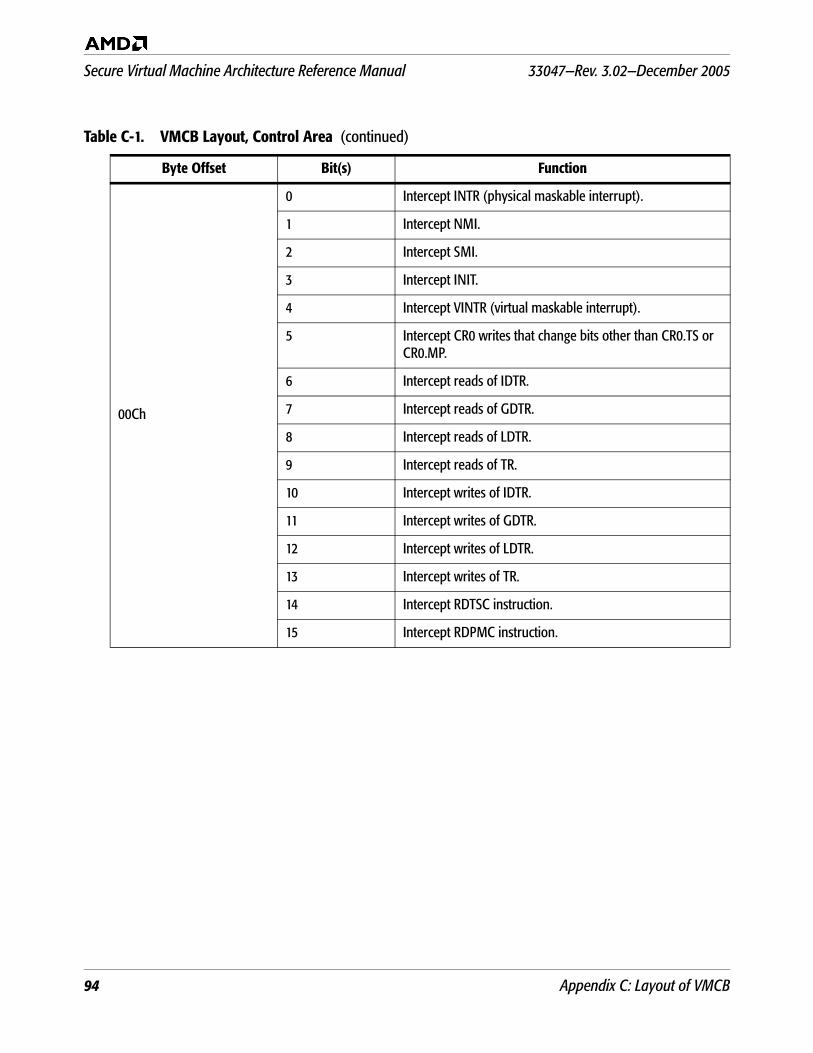
Secure Virtual Machine Architecture Reference Manual 33047—Rev. 3.02—December 2005
94 Appendix C: Layout of VMCB
00Ch
0 Intercept INTR (physical maskable interrupt).
1 Intercept NMI.
2 Intercept SMI.
3 Intercept INIT.
4 Intercept VINTR (virtual maskable interrupt).
5 Intercept CR0 writes that change bits other than CR0.TS or CR0.MP.
6 Intercept reads of IDTR.
7 Intercept reads of GDTR.
8 Intercept reads of LDTR.
9 Intercept reads of TR.
10 Intercept writes of IDTR.
11 Intercept writes of GDTR.
12 Intercept writes of LDTR.
13 Intercept writes of TR.
14 Intercept RDTSC instruction.
15 Intercept RDPMC instruction.
Table C-1. VMCB Layout, Control Area (continued)
Byte Offset Bit(s) Function
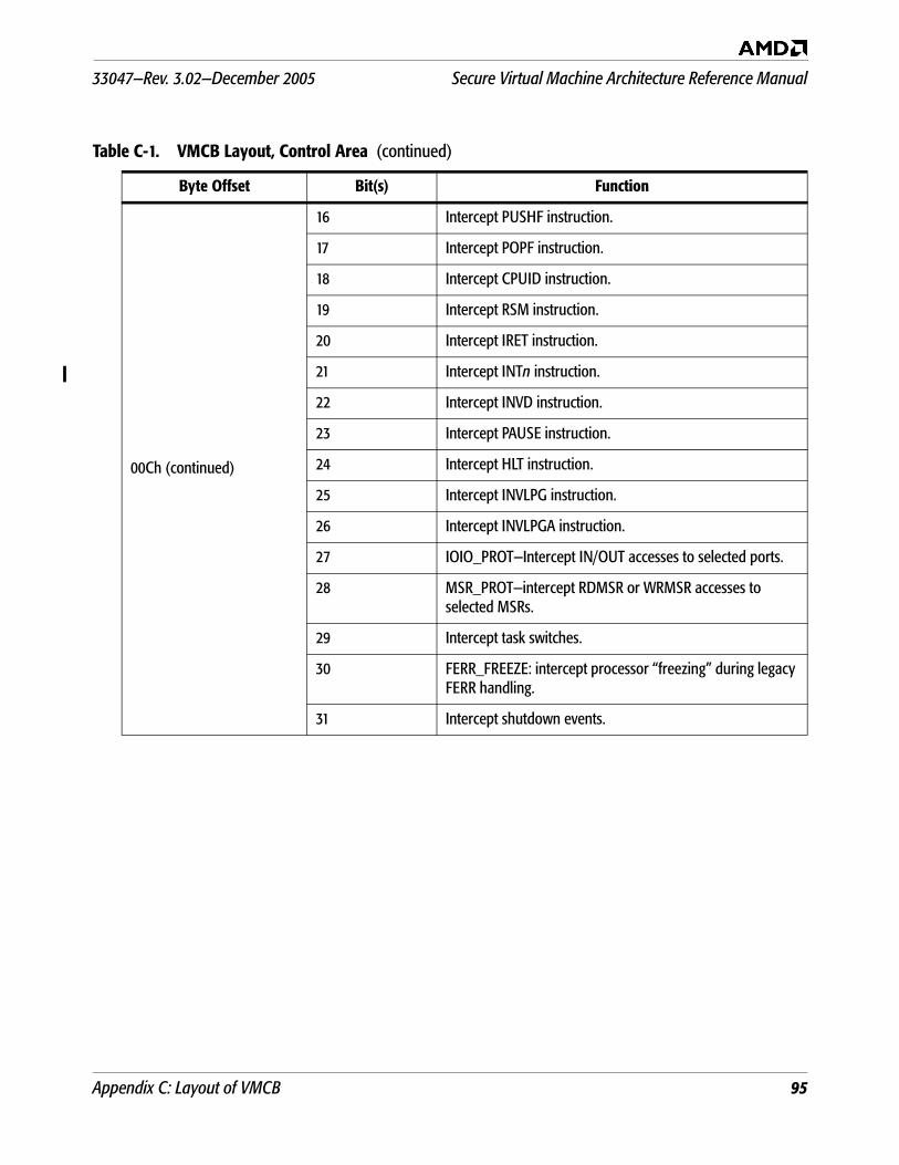
33047—Rev. 3.02—December 2005 Secure Virtual Machine Architecture Reference Manual
Appendix C: Layout of VMCB 95
00Ch (continued)
16 Intercept PUSHF instruction.
17 Intercept POPF instruction.
18 Intercept CPUID instruction.
19 Intercept RSM instruction.
20 Intercept IRET instruction.
21 Intercept INTn instruction.
22 Intercept INVD instruction.
23 Intercept PAUSE instruction.
24 Intercept HLT instruction.
25 Intercept INVLPG instruction.
26 Intercept INVLPGA instruction.
27 IOIO_PROT—Intercept IN/OUT accesses to selected ports.
28 MSR_PROT—intercept RDMSR or WRMSR accesses to selected MSRs.
29 Intercept task switches.
30 FERR_FREEZE: intercept processor “freezing” during legacy FERR handling.
31 Intercept shutdown events.
Table C-1. VMCB Layout, Control Area (continued)
Byte Offset Bit(s) Function
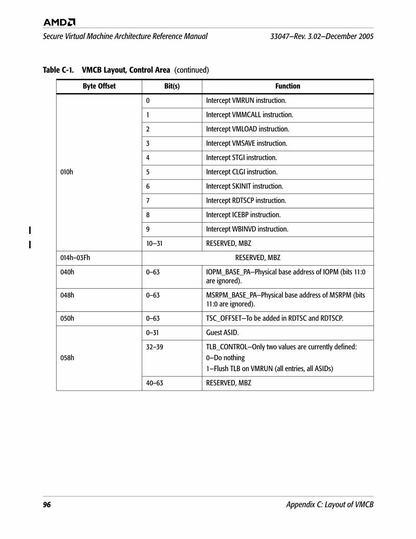
Secure Virtual Machine Architecture Reference Manual 33047—Rev. 3.02—December 2005
96 Appendix C: Layout of VMCB
010h
0 Intercept VMRUN instruction.
1 Intercept VMMCALL instruction.
2 Intercept VMLOAD instruction.
3 Intercept VMSAVE instruction.
4 Intercept STGI instruction.
5 Intercept CLGI instruction.
6 Intercept SKINIT instruction.
7 Intercept RDTSCP instruction.
8 Intercept ICEBP instruction.
9 Intercept WBINVD instruction.
10—31 RESERVED, MBZ
014h–03Fh RESERVED, MBZ
040h 0–63 IOPM_BASE_PA—Physical base address of IOPM (bits 11:0 are ignored).
048h 0–63 MSRPM_BASE_PA—Physical base address of MSRPM (bits 11:0 are ignored).
050h 0–63 TSC_OFFSET—To be added in RDTSC and RDTSCP.
058h
0–31 Guest ASID.
32–39 TLB_CONTROL—Only two values are currently defined:0—Do nothing1—Flush TLB on VMRUN (all entries, all ASIDs)
40–63 RESERVED, MBZ
Table C-1. VMCB Layout, Control Area (continued)
Byte Offset Bit(s) Function
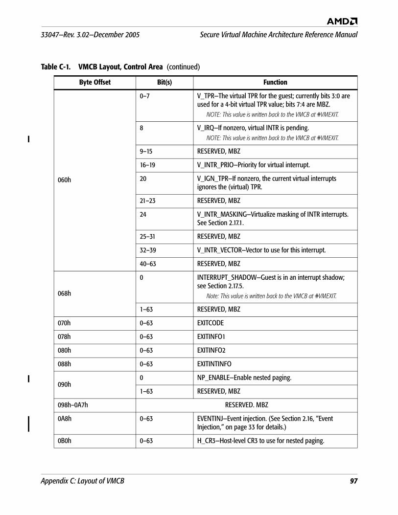
33047—Rev. 3.02—December 2005 Secure Virtual Machine Architecture Reference Manual
Appendix C: Layout of VMCB 97
060h
0–7 V_TPR—The virtual TPR for the guest; currently bits 3:0 are used for a 4-bit virtual TPR value; bits 7:4 are MBZ.
NOTE: This value is written back to the VMCB at #VMEXIT.
8 V_IRQ—If nonzero, virtual INTR is pending.NOTE: This value is written back to the VMCB at #VMEXIT.
9–15 RESERVED, MBZ
16–19 V_INTR_PRIO—Priority for virtual interrupt.
20 V_IGN_TPR—If nonzero, the current virtual interrupts ignores the (virtual) TPR.
21–23 RESERVED, MBZ
24 V_INTR_MASKING—Virtualize masking of INTR interrupts. See Section 2.17.1.
25–31 RESERVED, MBZ
32–39 V_INTR_VECTOR—Vector to use for this interrupt.
40–63 RESERVED, MBZ
068h
0 INTERRUPT_SHADOW—Guest is in an interrupt shadow; see Section 2.17.5.
Note: This value is written back to the VMCB at #VMEXIT.
1–63 RESERVED, MBZ
070h 0–63 EXITCODE
078h 0–63 EXITINFO1
080h 0–63 EXITINFO2
088h 0–63 EXITINTINFO
090h0 NP_ENABLE—Enable nested paging.
1–63 RESERVED, MBZ
098h–0A7h RESERVED. MBZ
0A8h 0–63 EVENTINJ—Event injection. (See Section 2.16, “Event Injection,” on page 33 for details.)
0B0h 0–63 H_CR3—Host-level CR3 to use for nested paging.
Table C-1. VMCB Layout, Control Area (continued)
Byte Offset Bit(s) Function
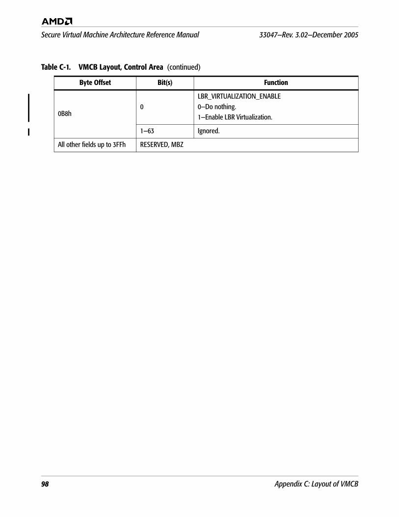
Secure Virtual Machine Architecture Reference Manual 33047—Rev. 3.02—December 2005
98 Appendix C: Layout of VMCB
0B8h0
LBR_VIRTUALIZATION_ENABLE0—Do nothing.1—Enable LBR Virtualization.
1—63 Ignored.
All other fields up to 3FFh RESERVED, MBZ
Table C-1. VMCB Layout, Control Area (continued)
Byte Offset Bit(s) Function
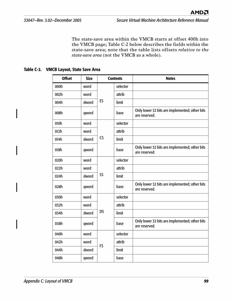
33047—Rev. 3.02—December 2005 Secure Virtual Machine Architecture Reference Manual
Appendix C: Layout of VMCB 99
The state-save area within the VMCB starts at offset 400h intothe VMCB page; Table C-2 below describes the fields within thestate-save area; note that the table lists offsets relative to thestate-save area (not the VMCB as a whole).
Table C-2. VMCB Layout, State Save Area
Offset Size Contents Notes
000h word
ES
selector
002h word attrib
004h dword limit
008h qword baseOnly lower 32 bits are implemented; other bits are reserved.
010h word
CS
selector
012h word attrib
014h dword limit
018h qword baseOnly lower 32 bits are implemented; other bits are reserved.
020h word
SS
selector
022h word attrib
024h dword limit
028h qword base Only lower 32 bits are implemented; other bits are reserved.
030h word
DS
selector
032h word attrib
034h dword limit
038h qword base Only lower 32 bits are implemented; other bits are reserved.
040h word
FS
selector
042h word attrib
044h dword limit
048h qword base
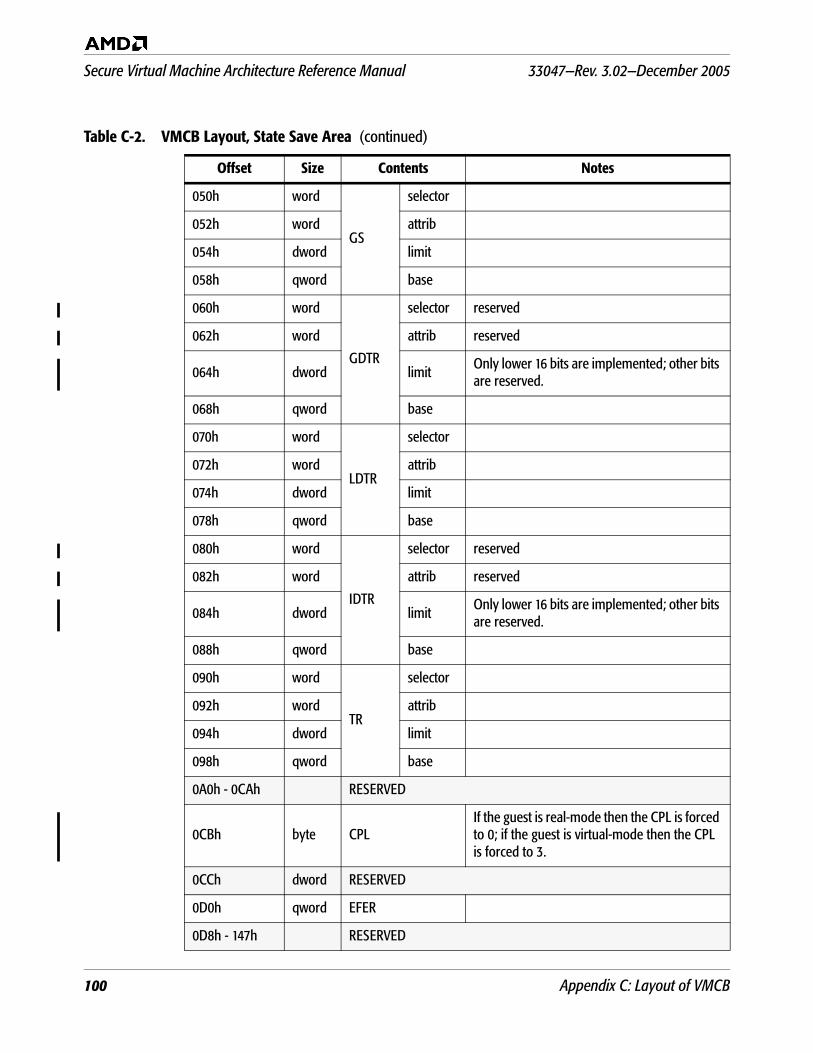
Secure Virtual Machine Architecture Reference Manual 33047—Rev. 3.02—December 2005
100 Appendix C: Layout of VMCB
050h word
GS
selector
052h word attrib
054h dword limit
058h qword base
060h word
GDTR
selector reserved
062h word attrib reserved
064h dword limit Only lower 16 bits are implemented; other bits are reserved.
068h qword base
070h word
LDTR
selector
072h word attrib
074h dword limit
078h qword base
080h word
IDTR
selector reserved
082h word attrib reserved
084h dword limit Only lower 16 bits are implemented; other bits are reserved.
088h qword base
090h word
TR
selector
092h word attrib
094h dword limit
098h qword base
0A0h - 0CAh RESERVED
0CBh byte CPLIf the guest is real-mode then the CPL is forced to 0; if the guest is virtual-mode then the CPL is forced to 3.
0CCh dword RESERVED
0D0h qword EFER
0D8h - 147h RESERVED
Table C-2. VMCB Layout, State Save Area (continued)
Offset Size Contents Notes
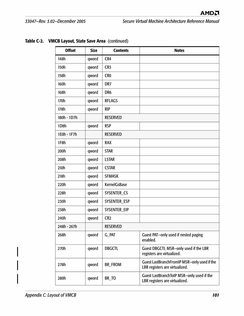
33047—Rev. 3.02—December 2005 Secure Virtual Machine Architecture Reference Manual
Appendix C: Layout of VMCB 101
148h qword CR4
150h qword CR3
158h qword CR0
160h qword DR7
168h qword DR6
170h qword RFLAGS
178h qword RIP
180h - 1D7h RESERVED
1D8h qword RSP
1E0h - 1F7h RESERVED
1F8h qword RAX
200h qword STAR
208h qword LSTAR
210h qword CSTAR
218h qword SFMASK
220h qword KernelGsBase
228h qword SYSENTER_CS
230h qword SYSENTER_ESP
238h qword SYSENTER_EIP
240h qword CR2
248h - 267h RESERVED
268h qword G_PAT Guest PAT—only used if nested paging enabled.
270h qword DBGCTL Guest DBGCTL MSR—only used if the LBR registers are virtualized.
278h qword BR_FROM Guest LastBranchFromIP MSR—only used if the LBR registers are virtualized.
280h qword BR_TOGuest LastBranchToIP MSR—only used if the LBR registers are virtualized.
Table C-2. VMCB Layout, State Save Area (continued)
Offset Size Contents Notes
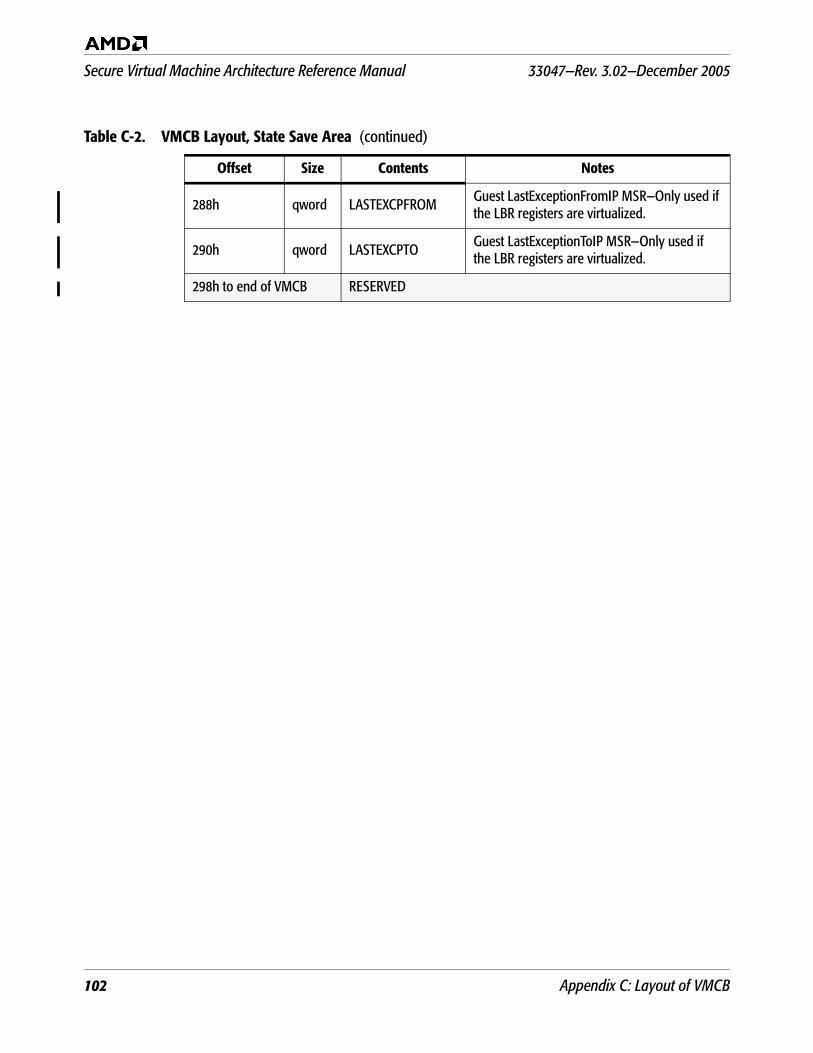
Secure Virtual Machine Architecture Reference Manual 33047—Rev. 3.02—December 2005
102 Appendix C: Layout of VMCB
288h qword LASTEXCPFROM Guest LastExceptionFromIP MSR—Only used if the LBR registers are virtualized.
290h qword LASTEXCPTO Guest LastExceptionToIP MSR—Only used if the LBR registers are virtualized.
298h to end of VMCB RESERVED
Table C-2. VMCB Layout, State Save Area (continued)
Offset Size Contents Notes
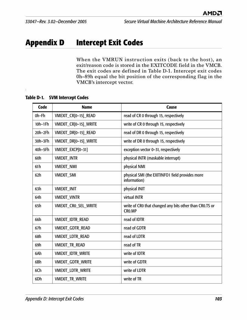
33047—Rev. 3.02—December 2005 Secure Virtual Machine Architecture Reference Manual
Appendix D: Intercept Exit Codes 103
Appendix D Intercept Exit Codes
When the VMRUN instruction exits (back to the host), anexit/reason code is stored in the EXITCODE field in the VMCB.The exit codes are defined in Table D-1. Intercept exit codes0h–89h equal the bit position of the corresponding flag in theVMCB’s intercept vector.
:
Table D-1. SVM Intercept Codes
Code Name Cause
0h–Fh VMEXIT_CR[0–15]_READ read of CR 0 through 15, respectively
10h–1Fh VMEXIT_CR[0–15]_WRITE write of CR 0 through 15, respectively
20h–2Fh VMEXIT_DR[0–15]_READ read of DR 0 through 15, respectively
30h–3Fh VMEXIT_DR[0–15]_WRITE write of DR 0 through 15, respectively
40h–5Fh VMEXIT_EXCP[0–31] exception vector 0–31, respectively
60h VMEXIT_INTR physical INTR (maskable interrupt)
61h VMEXIT_NMI physical NMI
62h VMEXIT_SMI physical SMI (the EXITINFO1 field provides more information)
63h VMEXIT_INIT physical INIT
64h VMEXIT_VINTR virtual INTR
65h VMEXIT_CR0_SEL_WRITE write of CR0 that changed any bits other than CR0.TS or CR0.MP
66h VMEXIT_IDTR_READ read of IDTR
67h VMEXIT_GDTR_READ read of GDTR
68h VMEXIT_LDTR_READ read of LDTR
69h VMEXIT_TR_READ read of TR
6Ah VMEXIT_IDTR_WRITE write of IDTR
6Bh VMEXIT_GDTR_WRITE write of GDTR
6Ch VMEXIT_LDTR_WRITE write of LDTR
6Dh VMEXIT_TR_WRITE write of TR
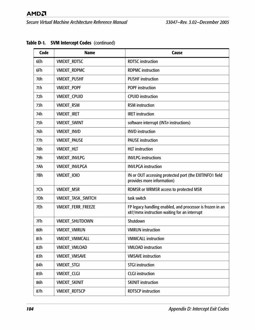
Secure Virtual Machine Architecture Reference Manual 33047—Rev. 3.02—December 2005
104 Appendix D: Intercept Exit Codes
6Eh VMEXIT_RDTSC RDTSC instruction
6Fh VMEXIT_RDPMC RDPMC instruction
70h VMEXIT_PUSHF PUSHF instruction
71h VMEXIT_POPF POPF instruction
72h VMEXIT_CPUID CPUID instruction
73h VMEXIT_RSM RSM instruction
74h VMEXIT_IRET IRET instruction
75h VMEXIT_SWINT software interrupt (INTn instructions)
76h VMEXIT_INVD INVD instruction
77h VMEXIT_PAUSE PAUSE instruction
78h VMEXIT_HLT HLT instruction
79h VMEXIT_INVLPG INVLPG instructions
7Ah VMEXIT_INVLPGA INVLPGA instruction
7Bh VMEXIT_IOIO IN or OUT accessing protected port (the EXITINFO1 field provides more information)
7Ch VMEXIT_MSR RDMSR or WRMSR access to protected MSR
7Dh VMEXIT_TASK_SWITCH task switch
7Eh VMEXIT_FERR_FREEZE FP legacy handling enabled, and processor is frozen in an x87/mmx instruction waiting for an interrupt
7Fh VMEXIT_SHUTDOWN Shutdown
80h VMEXIT_VMRUN VMRUN instruction
81h VMEXIT_VMMCALL VMMCALL instruction
82h VMEXIT_VMLOAD VMLOAD instruction
83h VMEXIT_VMSAVE VMSAVE instruction
84h VMEXIT_STGI STGI instruction
85h VMEXIT_CLGI CLGI instruction
86h VMEXIT_SKINIT SKINIT instruction
87h VMEXIT_RDTSCP RDTSCP instruction
Table D-1. SVM Intercept Codes (continued)
Code Name Cause
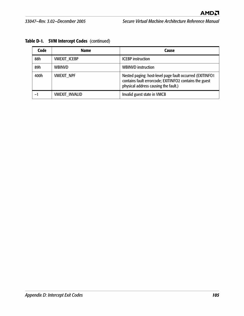
33047—Rev. 3.02—December 2005 Secure Virtual Machine Architecture Reference Manual
Appendix D: Intercept Exit Codes 105
88h VMEXIT_ICEBP ICEBP instruction
89h WBINVD WBINVD instruction
400h VMEXIT_NPF Nested paging: host-level page fault occurred (EXITINFO1 contains fault errorcode; EXITINFO2 contains the guest physical address causing the fault.)
–1 VMEXIT_INVALID Invalid guest state in VMCB
Table D-1. SVM Intercept Codes (continued)
Code Name Cause
Secure Virtual Machine Architecture Reference Manual 33047—Rev. 3.02—December 2005
106 Appendix D: Intercept Exit Codes
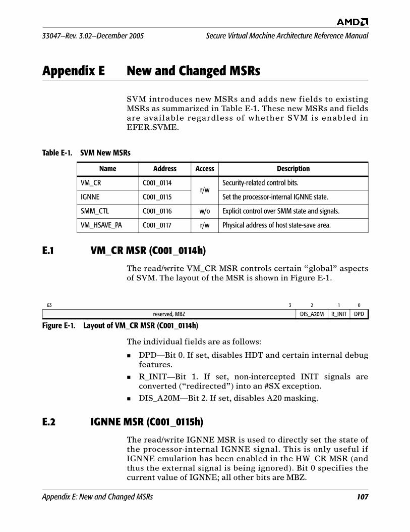
33047—Rev. 3.02—December 2005 Secure Virtual Machine Architecture Reference Manual
Appendix E: New and Changed MSRs 107
Appendix E New and Changed MSRs
SVM introduces new MSRs and adds new fields to existingMSRs as summarized in Table E-1. These new MSRs and fieldsare available regardless of whether SVM is enabled inEFER.SVME.
E.1 VM_CR MSR (C001_0114h)
The read/write VM_CR MSR controls certain “global” aspectsof SVM. The layout of the MSR is shown in Figure E-1.
The individual fields are as follows:
DPD—Bit 0. If set, disables HDT and certain internal debugfeatures.
R_INIT—Bit 1. If set, non-intercepted INIT signals areconverted (“redirected”) into an #SX exception.
DIS_A20M—Bit 2. If set, disables A20 masking.
E.2 IGNNE MSR (C001_0115h)
The read/write IGNNE MSR is used to directly set the state ofthe processor-internal IGNNE signal. This is only useful ifIGNNE emulation has been enabled in the HW_CR MSR (andthus the external signal is being ignored). Bit 0 specifies thecurrent value of IGNNE; all other bits are MBZ.
Table E-1. SVM New MSRs
Name Address Access Description
VM_CR C001_0114r/w
Security-related control bits.
IGNNE C001_0115 Set the processor-internal IGNNE state.
SMM_CTL C001_0116 w/o Explicit control over SMM state and signals.
VM_HSAVE_PA C001_0117 r/w Physical address of host state-save area.
63 3 2 1 0
reserved, MBZ DIS_A20M R_INIT DPD
Figure E-1. Layout of VM_CR MSR (C001_0114h)
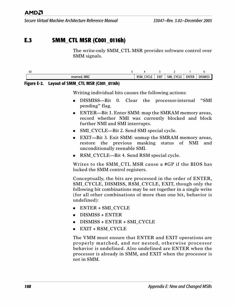
Secure Virtual Machine Architecture Reference Manual 33047—Rev. 3.02—December 2005
108 Appendix E: New and Changed MSRs
E.3 SMM_CTL MSR (C001_0116h)
The write-only SMM_CTL MSR provides software control overSMM signals.
Writing individual bits causes the following actions:
DISMISS—Bit 0. Clear the processor-internal “SMIpending” flag.
ENTER—Bit 1. Enter SMM: map the SMRAM memory areas,record whether NMI was currently blocked and blockfurther NMI and SMI interrupts.
SMI_CYCLE—Bit 2. Send SMI special cycle.
EXIT—Bit 3. Exit SMM: unmap the SMRAM memory areas,restore the previous masking status of NMI andunconditionally reenable SMI.
RSM_CYCLE—Bit 4. Send RSM special cycle.
Writes to the SMM_CTL MSR cause a #GP if the BIOS haslocked the SMM control registers.
Conceptually, the bits are processed in the order of ENTER,SMI_CYCLE, DISMISS, RSM_CYCLE, EXIT, though only thefollowing bit combinations may be set together in a single write(for all other combinations of more than one bit, behavior isundefined):
ENTER + SMI_CYCLE
DISMISS + ENTER
DISMISS + ENTER + SMI_CYCLE
EXIT + RSM_CYCLE
The VMM must ensure that ENTER and EXIT operations areproperly matched, and not nested, otherwise processorbehavior is undefined. Also undefined are ENTER when theprocessor is already in SMM, and EXIT when the processor isnot in SMM.
63 5 4 3 2 1 0
reserved, MBZ RSM_CYCLE EXIT SMI_CYCLE ENTER DISMISS
Figure E-2. Layout of SMM_CTL MSR (C001_0116h)
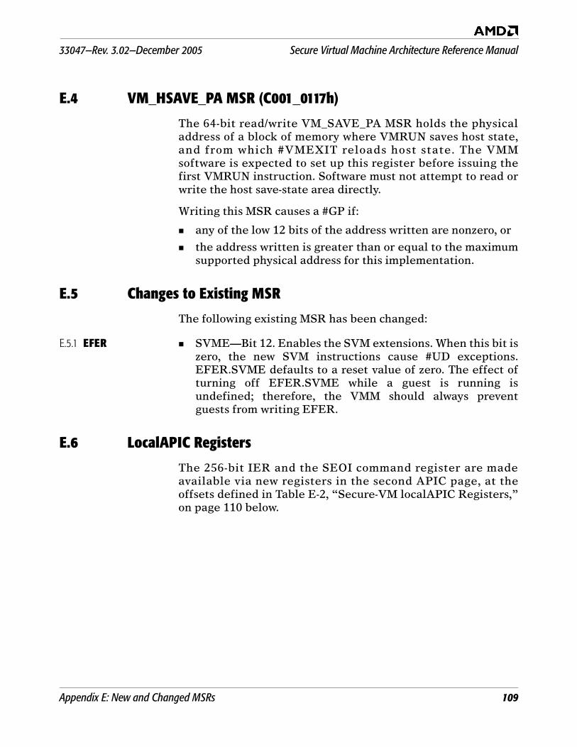
33047—Rev. 3.02—December 2005 Secure Virtual Machine Architecture Reference Manual
Appendix E: New and Changed MSRs 109
E.4 VM_HSAVE_PA MSR (C001_0117h)
The 64-bit read/write VM_SAVE_PA MSR holds the physicaladdress of a block of memory where VMRUN saves host state,and from which #VMEXIT reloads host state. The VMMsoftware is expected to set up this register before issuing thefirst VMRUN instruction. Software must not attempt to read orwrite the host save-state area directly.
Writing this MSR causes a #GP if:
any of the low 12 bits of the address written are nonzero, or
the address written is greater than or equal to the maximumsupported physical address for this implementation.
E.5 Changes to Existing MSR
The following existing MSR has been changed:
E.5.1 EFER SVME—Bit 12. Enables the SVM extensions. When this bit iszero, the new SVM instructions cause #UD exceptions.EFER.SVME defaults to a reset value of zero. The effect ofturning off EFER.SVME while a guest is running isundefined; therefore, the VMM should always preventguests from writing EFER.
E.6 LocalAPIC Registers
The 256-bit IER and the SEOI command register are madeavailable via new registers in the second APIC page, at theoffsets defined in Table E-2, “Secure-VM localAPIC Registers‚”on page 110 below.
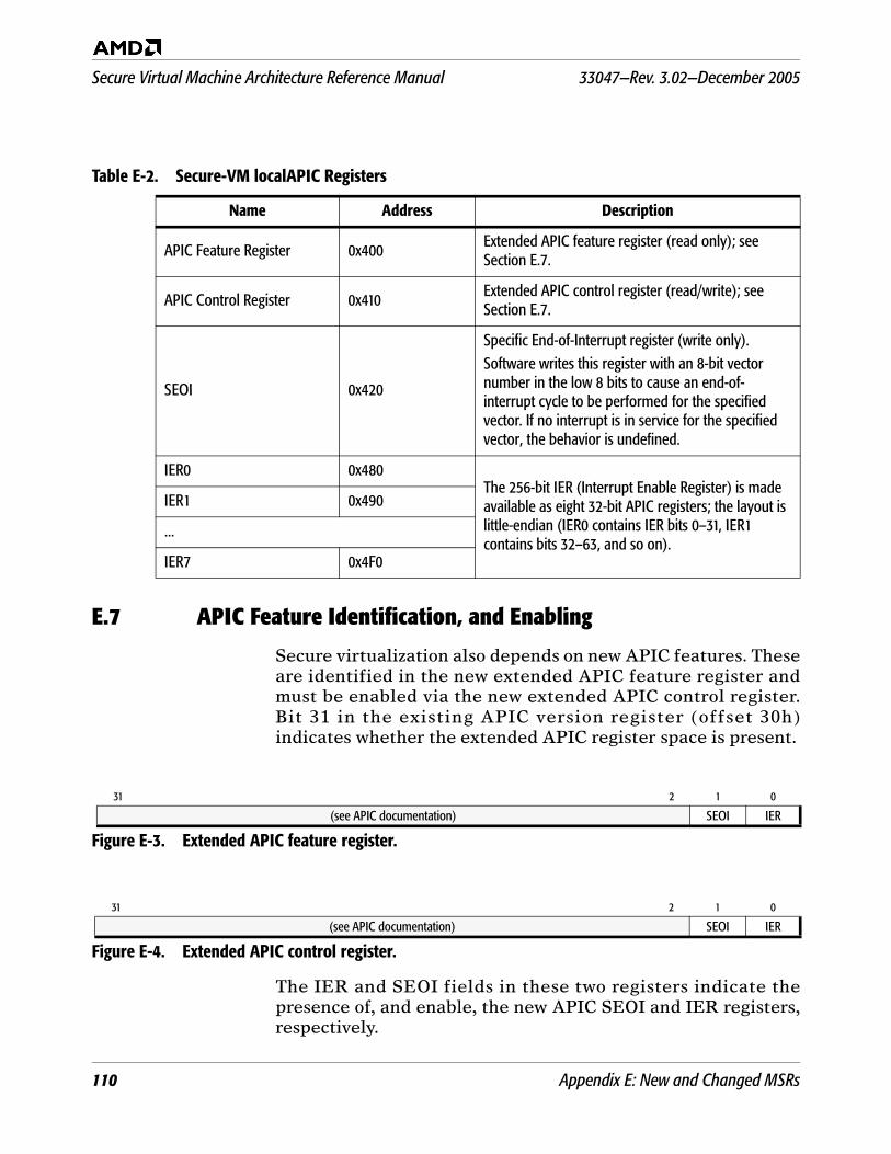
Secure Virtual Machine Architecture Reference Manual 33047—Rev. 3.02—December 2005
110 Appendix E: New and Changed MSRs
E.7 APIC Feature Identification, and Enabling
Secure virtualization also depends on new APIC features. Theseare identified in the new extended APIC feature register andmust be enabled via the new extended APIC control register.Bit 31 in the existing APIC version register (offset 30h)indicates whether the extended APIC register space is present.
The IER and SEOI fields in these two registers indicate thepresence of, and enable, the new APIC SEOI and IER registers,respectively.
Table E-2. Secure-VM localAPIC Registers
Name Address Description
APIC Feature Register 0x400 Extended APIC feature register (read only); see Section E.7.
APIC Control Register 0x410 Extended APIC control register (read/write); see Section E.7.
SEOI 0x420
Specific End-of-Interrupt register (write only).Software writes this register with an 8-bit vector number in the low 8 bits to cause an end-of-interrupt cycle to be performed for the specified vector. If no interrupt is in service for the specified vector, the behavior is undefined.
IER0 0x480The 256-bit IER (Interrupt Enable Register) is made available as eight 32-bit APIC registers; the layout is little-endian (IER0 contains IER bits 0–31, IER1 contains bits 32–63, and so on).
IER1 0x490
...
IER7 0x4F0
31 2 1 0
(see APIC documentation) SEOI IER
Figure E-3. Extended APIC feature register.
31 2 1 0
(see APIC documentation) SEOI IER
Figure E-4. Extended APIC control register.