Embed Size (px)
Citation preview

Secure Managed Client Version 2.0Deployment GuideDate: February 26, 2010

Secure Managed Client Version 2.0Deployment GuideDate: February 26, 2010

First Edition (February 2010)
© Copyright Lenovo 2009, 20010.
LENOVO products, data, computer software, and services have been developed exclusively at private expense andare sold to governmental entities as commercial items as defined by 48 C.F.R. 2.101 with limited and restrictedrights to use, reproduction and disclosure.
LIMITED AND RESTRICTED RIGHTS NOTICE: If products, data, computer software, or services are deliveredpursuant a General Services Administration ″GSA″ contract, use, reproduction, or disclosure is subject to restrictionsset forth in Contract No. GS-35F-05925.

Preface
This guide is intended for IT administrators, or those who are responsible fordeploying the Secure Managed Client® (SMC) program on computers in theirorganizations. The purpose of this guide is to provide the information required forinstalling, tuning, and best practices for Secure Managed Client.
Secure Managed Client is developed for IT professionals and the unique challengesthey encounter. This deployment guide will provide instructions and solutions forworking with Secure Managed Client. If you have suggestions or comments,communicate with your Lenovo® authorized representative. To check for periodicupdates to this guide, visit the following Web site:www.lenovo.com
© Copyright Lenovo 2009, 20010 iii

iv Secure Managed Client Version 2.0 Deployment Guide
Contents
Preface . . . . . . . . . . . . . . . iii
Chapter 1. Overview . . . . . . . . . 1
Chapter 2. General setup . . . . . . . 3Networking. . . . . . . . . . . . . . . 3Installing and configuring LANDesk . . . . . . 3Provisioning the storage array . . . . . . . . 3Building a base image . . . . . . . . . . . 3Creating user images . . . . . . . . . . . 3
Selecting the type of image you wish to use . . . 3
Chapter 3. Networking considerations . . 5Infrastructure requirements . . . . . . . . . 5Diskless client architecture . . . . . . . . . . 6Active Directory considerations . . . . . . . . 6iSCSI boot . . . . . . . . . . . . . . . 7Capacity . . . . . . . . . . . . . . . . 7Link aggregation (Bonding) . . . . . . . . . 7Packet loss . . . . . . . . . . . . . . . 8Network topology . . . . . . . . . . . . 8
Chapter 4. Secure Managed Clientspecific installation . . . . . . . . . . 9Prerequisites . . . . . . . . . . . . . . 9Secure Managed Client manual setup. . . . . . 10
Secure Managed Client switches . . . . . . 11Secure Managed Client - Storage Array setup . . . 11Secure Managed Client management coreinstallation . . . . . . . . . . . . . . 12Secure Managed Client Storage Array provisioning 12
Chapter 5. LANDesk Information. . . . 13Secure Managed Client / LANDesk setup . . . . 13
Retrieving the Secure Managed Client Console 13Prerequisites . . . . . . . . . . . . . 13Installing LANDesk . . . . . . . . . . 14Upgrading from Secure Managed Client version1.2 to 2.0 . . . . . . . . . . . . . . 14Configuring the LANDesk Secure ManagedClient console . . . . . . . . . . . . 15
Image types . . . . . . . . . . . . . . 18Standard image . . . . . . . . . . . . 18Single image . . . . . . . . . . . . . 18Local cache image . . . . . . . . . . . 19Assigned seating . . . . . . . . . . . 20
Pristine image . . . . . . . . . . . . . 21
Chapter 6. Secure Managed Clientimage creation and tuning . . . . . . 23Creating Sysprep images . . . . . . . . . . 23
Preparing a Windows XP image . . . . . . 23Cloning an existing Windows XP image . . . . 24
Preparing a Windows Vista image . . . . . . 24Image optimization . . . . . . . . . . . . 34
Scheduled tasks . . . . . . . . . . . . 34Application compatibility testing . . . . . . 36Operating system services . . . . . . . . 37Recommendations . . . . . . . . . . . 38
Roaming user profiles and folder redirection . . . 39
Chapter 7. Populating a base image . . 41Using bootable CD/DVD media . . . . . . . 41
SMCWinPE.iso . . . . . . . . . . . . 42Connecting to a target image LUN on an SMCStorage Array using the iSCSI Initiator . . . . 42Copying a multiple partition image to the storagearray, version 1.x . . . . . . . . . . . 43Copying a multiple partition image to the storagearray, Version 2.0 . . . . . . . . . . . 44
Deploying the image directly to the storage array . 45Boot acceleration . . . . . . . . . . . . 46Hints and tips . . . . . . . . . . . . . 46If not using a Lenovo CD. . . . . . . . . . 47
Chapter 8. Setting up network shares 49
Chapter 9. Configuring synchronousand asynchronous replication. . . . . 51Prerequisites . . . . . . . . . . . . . . 51Creating synchronous replication . . . . . . . 51Creating asynchronous replication . . . . . . . 52Manual failover . . . . . . . . . . . . . 52
Chapter 10. Troubleshooting . . . . . 53Problems . . . . . . . . . . . . . . . 53
Storage array diagnostics . . . . . . . . . 53Secure Managed Client will not boot . . . . . 53Clients will not boot after moving theManagement Console . . . . . . . . . . 53Management Core Server IP address has changed 54Provisioning fails . . . . . . . . . . . 54No user image . . . . . . . . . . . . 54
LANDesk logs . . . . . . . . . . . . . 54Unique network failure points . . . . . . . . 54Binding order in the Secure Managed Clientenvironment . . . . . . . . . . . . . . 55
Changing the binding order for Windows XP . . 55Changing the binding order for Windows Vista 55
Limitations . . . . . . . . . . . . . . 56
Appendix. Notices . . . . . . . . . . 59Trademarks . . . . . . . . . . . . . . 60
Glossary . . . . . . . . . . . . . . 61
© Copyright Lenovo 2009, 20010 v

vi Secure Managed Client Version 2.0 Deployment Guide

Chapter 1. Overview
The Lenovo Secure Managed Client solution is a storage-based alternative clientcomputing solution, designed to help businesses reduce support costs and increasedata security while offering users the flexibility and performance of a traditionaldesktop PC. Secure Managed Client delivers standard or customized desktopimages directly from a storage array to ThinkCentre M57p eco, M58, or M58pclients. The software and data are all centrally administered using the SecureManaged Client Management Console. The Secure Managed Client solution isdesigned to reduce ongoing maintenance costs, which significantly add up overtime.
The Secure Managed Client solution consists of three major components:v Secure Managed Clients: The clients consist of Lenovo diskless ThinkCentre
M-series desktop computers using Intel vPro® technology. The clients areconfigured to boot directly from the Secure Managed Client Storage Array.
v Storage Array: The Secure Managed Client Storage Array is the centralized datarepository for the Secure Managed Clients. It is a rack mount, fully populated 12x 3.5-inch Serial ATA (SATA) hard disk drive (HDD) enclosure, optimized toprovide iSCSI-based traffic through the use of 6 x 1 GB Ethernet ports. Thestorage system is designed to host up to 100 active client hard disk drives.
v Software Stack: The Secure Managed Client Software Stack connects the SecureManaged Clients to user images on the storage array. The Secure ManagedClient Management Console provides administration of the storage array andeach individual client through technology provided by LANDesk software.
© Copyright Lenovo 2009, 20010 1

2 Secure Managed Client Version 2.0 Deployment Guide
Chapter 2. General setup
The following are check lists to help you quickly set up your Secure ManagedClient environment. This is the suggested order in which to set up yourenvironment.
Networking__ Step 1. “Infrastructure requirements” on page 5__ Step 2. “Diskless client architecture” on page 6__ Step 3. “Active Directory considerations” on page 6__ Step 4. “iSCSI boot” on page 7__ Step 5. “Capacity” on page 7__ Step 6. “Network topology” on page 8
Installing and configuring LANDesk__ 1. “Prerequisites” on page 13__ 2. “Installing LANDesk” on page 14__ 3. “Retrieving the Secure Managed Client Console” on page 13__ 4. “Starting LANDesk Management Suite” on page 15__ 5. “Creating a standard base image” on page 16__ 6. Chapter 7, “Populating a base image,” on page 41__ 7. “Creating a standard image or single image user image” on page 16
Provisioning the storage array__ Step 1. “Provisioning the storage array” on page 16
Building a base image__ 1. Configuring a donor client__ 2. “Creating Sysprep images” on page 23__ 3. Create/upload a base image “Creating a standard base image” on page 16
Creating user images
Selecting the type of image you wish to use__ 1. Select the type of image that you wish to use. Here is a list of the image
types.v Secure Managed Client standard image
v Single image
v Local cache
© Copyright Lenovo 2009, 20010 3

Table 1 provides a description of the different image types:
Table 1. Image types
Image Type Features Additional information
Standard image v One image per user, everyuser has a unique image
v Requires more storage onstorage array per user.
v Supports assigned seating
v Supports pristine image
v Chapter 6, “SecureManaged Client imagecreation and tuning,” onpage 23
v “Assigned seating” onpage 20
v “Pristine image” on page21
Single image v Created from commonbase image
v Supports assigned seating
v Supports personal orpristine image; default ispersonal.
v “Single image” on page 18
v “Assigned seating” onpage 20
v “Pristine image” on page21
Local cache image v Created from commonbase image
v No assigned seating
v Stores image on localdrive.
v Fast boot, goodperformance
v User’s changes storedseparately on storage array
v Supports pristine image
v “Local cache image” onpage 19
v “Pristine image” on page21
__ 2. Creating Users__ 3. Deploying images “Deploying the image directly to the storage array” on
page 45
4 Secure Managed Client Version 2.0 Deployment Guide

Chapter 3. Networking considerations
This chapter discusses requirements and other considerations when setting upSecure Managed Client.
Included in this chapter are the following topics:v “Infrastructure requirements”v “Diskless client architecture” on page 6v “Active Directory considerations” on page 6v “iSCSI boot” on page 7v “Capacity” on page 7v “Link aggregation (Bonding)” on page 7v “Packet loss” on page 8v “Network topology” on page 8
Infrastructure requirementsThe following are preferred network requirements:v Multi GB backbonev The Secure Managed Client Storage Array has 6 1-GB ports combinedv The switches are placed between the storage array and client only
The following are alternate networking requirements:v A 1 GB or faster backbonev A maximum of 20 clients per 1 GB linkv At a minimum, a 100 MB switch
– A Gigabit uplink is required– Max of 20 clients per 100 MB switch with a 1 GB uplink
v Will support a routed network– Not recommended for Secure Managed Client– Must meet above network requirements– Prefer 10-GB router
v Secure Managed Client uses two media access control (MAC)s sub-layers perclient
v Not compatible with network access control (NAC)– Booting through iSCSI requires network access– Network interface card (NIC) OPROM does not support NAC
© Copyright Lenovo 2009, 20010 5
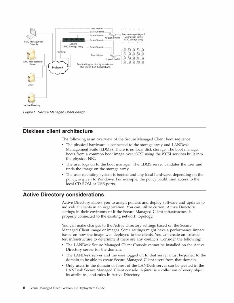
Diskless client architectureThe following is an overview of the Secure Managed Client boot sequence:v The physical hardware is connected to the storage array and LANDesk
Management Suite (LDMS). There is no local disk storage. The boot managerboots from a common boot image over iSCSI using the iSCSI services built intothe physical NIC.
v The user logs on to the boot manager. The LDMS server validates the user andfinds the image on the storage array.
v The user operating system is booted and any local hardware, depending on thepolicy, is given to Windows. For example, the policy could limit access to thelocal CD ROM or USB ports.
Active Directory considerationsActive Directory allows you to assign policies and deploy software and updates toindividual clients in an organization. You can utilize current Active Directorysettings in their environment if the Secure Managed Client infrastructure isproperly connected to the existing network topology.
You can make changes to the Active Directory settings based on the SecureManaged Client image or images. Some settings might have a performance impactbased on how the image was deployed to the clients. You can create an isolatedtest infrastructure to determine if there are any conflicts. Consider the following:v The LANDesk Secure Managed Client Console cannot be installed on the Active
Directory server for the domain.v The LANDesk server and the user logged on to that server must be joined to the
domain to be able to create Secure Managed Client users from that domain.v Only users in the domain or forest of the LANDesk server can be created in the
LANDesk Secure Managed Client console. A forest is a collection of every object,its attributes, and rules in Active Directory
SMC ManagementConsole
SMC ManagementServer
DHCP
Active Directory
Network
LenovoSMC Storage Array
Disc traffic goes directly to switches.This keeps it off the backbone.
20 systems per gigabitConnection to theSMC storage array
20 systems per gigabitConnection to theSMC storage array
20 systems per gigabitConnection to theSMC storage array
Gigabit Switch
Gigabit Switch
Corp Network
SMC mgt
SAN HDD traffic
SAN HDD traffic
SAN HDD traffic
SAN HDD traffic
Corp Network
Figure 1. Secure Managed Client design
6 Secure Managed Client Version 2.0 Deployment Guide
For more information on Active Directory, go to the following Web address:http://www.microsoft.com/windowsserver2003/technologies/directory/activedirectory/default.mspx
iSCSI bootSecure Managed Client conforms to the iSCSI standard protocol. Make sure thatport 3260 is not blocked so as not to block iSCSI traffic. For more information, seewww.ietf.org
The initial operating system (the boot manager) is loaded into the client throughan iSCSI boot by the NIC. The Dynamic Host Configuration Protocol (DHCP)server must be configured to tell the NIC which iSCSI target to load. The DHCPserver conveys the IP address, the target name, and the Logical Unit Number(LUN) number in the boot option of the DHCP configuration. The specific syntaxand method (or syntax or method) depends on the kind of DHCP server used inthe customer environment and is, therefore, beyond the scope of this book.
An iSCSI target is a string or tag that is recognized by the iSCSI target service asmapping to a file or device. In the case of Secure Managed Client, the iSCSI serviceruns in the storage array and the target (or tag) is generated by a combination ofthe storage array and the LANDesk server. The prefix of the target name isgenerated by the storage array so that it is guaranteed to be unique. The remainderof the name is generated by LANDesk and is usually smcboot.
To find the boot manager target name, perform an iSCSI discovery to the storagearray IP address. This will return a list of targets in the storage array. One of thesetargets should be the smcboot target. The DHCP server should set the target namein the iSCSI boot configuration to be this name (including the storagearray-generated unique prefix). If the IP address is statically assigned, the LUNwill normally be 0.
CapacityThe general activity generated by Secure Managed Client is relatively small, butthe network should be designed for peak capacity. While peak access on differentsystems will rarely occur at the same time, there may be times when severalsystems are booting at the same time. The network topology should be createdwith these times, known as boot storms, in mind.
A single 100 Mb line is able to support a single user but as multiple clients added,the capacity of the 100 Mb line will be exceeded and you might need a 1 Gb line.A 1 Gb line can carry the peak traffic of 20 to 25 clients. More clients will requiremultiple lines.
Link aggregation (Bonding)If the number of clients through a particular link exceeds 20 to 25, then multiplephysical links can be combined into a single logical link with greater capacity. Linkaggregation is in accordance with ISO 802.3AD but varies by switch manufacturer.
In the Secure Managed Client solution, a 6-wide aggregate link is used between thestorage array and the main switch. This allows the storage array to have a singleIP address and have enough network capacity for up to 100 clients.
Chapter 3. Networking considerations 7
If you notice MAC flapping or duplicate packet error message in your switch log,you can set up an Etherchannel across the 6 switch ports that you assign to thestorage array.
Note: If you need to reprovision the storage array, you will have to remove thisEtherchannel for the reprovisioning to be successful. See “Provisioning the storagearray” on page 16
Packet lossIf Secure Managed Client has poor performance when first deployed, the networkshould be checked for packet loss. Packet loss occurs when one or more datapackets fail to reach their destination over a computer network. This can happenfor various reasons: signal degradation, network problems, overloaded networklinks, or corrupted packets. If the packets are lost using network based technologythere can be a significant performance impact. It is important to remember thatsome packet loss is expected. Modern infrastructures tend to have an acceptablepacket loss rate of one percent. Packet loss in the Secure Managed Clientenvironment can impact client performance since the clients are virtualized over anetwork. It is important to consider this issue when selecting hardware for theSecure Managed Client infrastructure.
If the Secure Managed Client environment contains managed (smart) switches, it ispossible to measure packet loss through the individual ports. This is the preferredmethod as it provides data at the switch level. However, if the packet loss occursat the switch, it might not detect the dropped packets. Dropped packets in theswitch’s statistics are usually drops that it detects due to issues such as framingerrors or bit errors. These are not the same as packets being dropped due to errorsin distributing the packets across multiple physical links. Another way to check fordropped packets is to use a network performance tool that floods the network withpackets and then checks to see that they are being delivered correctly. An exampleis Issuing the Linux ping –f command.
Another way to measure packet loss is to place a node in between the hardware.For example, a Windows or Linux machine with two network cards can be placedbetween a single client and its respective switch.
Network topologyA typical topology in a Secure Managed Client solution would consist of:v A central switch with the 6 1 GB links aggregated to the storage arrayv 4 to 5 satellite switches, each with 1 GB links to the central switchv 0 to 25 clients per satellite switch with 1 GB or 100 Mb links
8 Secure Managed Client Version 2.0 Deployment Guide

Chapter 4. Secure Managed Client specific installation
This chapter includes prerequisites and procedures for installing the SecureManaged Client solution.
Included in this chapter are the following topics:v “Prerequisites”v “Secure Managed Client manual setup” on page 10v “Secure Managed Client - Storage Array setup” on page 11v “Secure Managed Client management core installation” on page 12v “Secure Managed Client Storage Array provisioning” on page 12
PrerequisitesThe following section details prerequisites for installing the Secure Managed Clientsolution:v Two preconfigured static IP addresses; one for the Secure Managed Client
Management Core and one for the Secure Managed Client Storage Array.v A DHCP root path (option 17) to set up with the storage array number that is
created once the storage array is provisioned.v Microsoft® Windows 2003 Server® for the Secure Managed Client Management
Core Server.v Any customer-specific server setup information that can affect installation of the
Secure Managed Client Management Core Server, such as security templates andGlobal Policy Objects (GPO)s.
v Allocated space in a wiring closet.v Client configuration:
– Windows® XP with SP 2 (3 recommended) minimum 1 GB memory (2recommended)
– Windows Vista® with (SP1 or later) with minimum 2 GB memory (3recommended)
v A customer desktop image for ThinkCentre® M57p M58, or M58p machines.
Notes:
1. Windows 7 is not supported at this time.2. Include virtual Secure Managed Client NIC drivers.3. Do not base computer naming on hardware since these are virtual devices.
v Any network security policies and network configuration that can be shared.v Verify that the Secure Managed Client router supports teaming.v Storage array:
Table 2. Storage array hard disk drive size
Storage Array: Effective Secure Managed Client User HDD Size
Number of UserImages 6 TB Storage Array 9 TB storage array 12 TB storage array
150 35 GB / client 50 GB / client 70 GB / client
100 50 GB / client 75 GB / client 100 GB / client
© Copyright Lenovo 2009, 20010 9

Table 2. Storage array hard disk drive size (continued)
Storage Array: Effective Secure Managed Client User HDD Size
Number of UserImages 6 TB Storage Array 9 TB storage array 12 TB storage array
50 100 GB / client 150 GB / client 200 GB / client
To calculate the number of users that can be placed on a storage array, use thefollowing formula:
Number of users = [(11* disk size -15) / (base image size)] - 2.5 * number of base images
Notes:
1. All sizes are in gigabytes.2. 15 represents 15 GB of reserved space for Secure Managed Client boot images
and management data.3. The maximum number of unique images that can be placed on a single storage
array is 250.4. The maximum number of active users on a single storage array is 150.5. Performance of the Secure Managed Client solution is impacted by the number
of active users.
Secure Managed Client manual setup1. Flash the BIOS on the machine with the latest Secure Managed Client Flash
BIOS update.2. If the system has a hard disk drive, unplug the drive connector.3. Reboot and press F1 to boot into the BIOS setup screen.4. Press F9 Setup Defaults to set defaults before making any changes.5.
v For M57 machines: In IDE Drives Setup, set Serial ATA to Enabled, NativeMode Operation to Serial ATA, SATA Raid Enable to Disabled, and SATAAHCI Enable to Disabled.
v For M58 machines, In ATA Drives Setup, set External SATA Port toEnabled, Serial ATA to Enabled, Native Mode Operation to Enabled, SATARaid Enable to Disabled, and SATA AHCI Enable to Disabled.
6.
v For M57 machines: In Network Setup, set LAN options ROM to SMC Boot.v For M58 machines: In Network Setup, set Boot Agent to SMC.
7. Include PCI SCSI in the startup sequence.8. Exclude IDE HDD from the startup sequence.9.
v For M57 machines: In Advanced, set Intel Virtualization Technology toEnabled.
v For M58 machines: In Advanced, CPU Setup, set Intel VirtualizationTechnology to Enabled.
10. Press F10 to save and restart.11. Perform a hard shutdown by powering off the machine.12. Turn the machine on and press Ctrl and D when you see the Intel iSCSI Boot
screen, which appears immediately after the first Lenovo splash screen.
10 Secure Managed Client Version 2.0 Deployment Guide

13. Press P to set the boot as primary.If the root path has been configured on the DHCP server, proceed to step 23.
14. Press Enter to access the iSCSI Port Configuration menu.15. Select iSCSI Boot Configuration.16. Press the Tab key Tab twice to Use DHCP for iSCSI Target Information and
press the space bar to deselect that option.17. Press the Tab key and type in the Target Name for your customer
environment installation.18. Press the Tab key. Enter the IP address of the server in the Target IP field.19. Press the Tab key for the next two fields and keep the defaults.20. Press the Tab key until you see OK and press Enter.21. Press the down arrow to save the changes, then exit.22. Click Enter and select Yes for confirmation.23. Click Esc; the Secure Managed Client system should begin booting normally.
Secure Managed Client switchesThere are two unique switches for SMCsetup.exe. They are:v NOCRED
When set to 1, does not install the credential provider SSO:SMCSetup.exe /v NOCRED=1
v NODISKSTATWhen set to 1, does not install the Disk Performance Monitor:SMCSetup.exe /v NODISKSTAT=1
Secure Managed Client - Storage Array setupThe Product Recovery CD for Secure Managed Client should be preloaded. If not,use an approved universal serial bus (USB) CD-ROM for installing it. Wheninstalling, select all defaults and perform the additional steps necessary to set upthe storage array. The suggested installation location for the storage array is in awiring closet plugged directly into the switches used for the Secure ManagedClient. This will keep the hard disk drive traffic from the corporate network.
To set up the storage array, do the following:1. Install the storage array.2. Connect all six network cables.3. Connect the keyboard and monitor to the storage array.4. When the storage array starts, enter the default password, which is password.
LANDesk will change this password when the server is provisioned.5. Select SysInfo and make sure that an IP address exists on all ports.6. Select IPConf and press Enter.7. Select NIC 1 and press the spacebar.8. Arrow down to Configure NIC and press Enter.9. Select Static IP address.
10. Enter the pre-setup Static IP address information:v IP addressv Subnet Mask
Chapter 4. Secure Managed Client specific installation 11
v Default Gatewayv Primary DNSv Secondary DNSv DNS suffix
11. Press Enter. This operation will take a couple of minutes while the IPinformation is being reset.
12. Press Esc to return to the main menu.13. Select Logoff from console.
Secure Managed Client management core installationFor detailed information on installing and configuring the LANDesk Secure ClientManagement software, see Chapter 5, “LANDesk Information,” on page 13.
Secure Managed Client Storage Array provisioningThe storage array is provisioned through the LANDesk Secure Managed Clientsoftware. See Chapter 5, “LANDesk Information,” on page 13 for moreinformation.
12 Secure Managed Client Version 2.0 Deployment Guide
Chapter 5. LANDesk Information
LANDesk Management Suite provides a full range of system management toolsthat let you view, configure, manage, and protect devices on your network. All ofthese tasks can be performed by a single console. This chapter describes theinstallation process for the LANDesk software and the necessary operations toconfigure Secure Managed Client through the LANDesk SMC manager. For moreinformation on other features provided by LANDesk Management Suite, see theLANDesk Management Suite User’s Guide at the following Web address:http://www.landesk.com/supportdownload/resourcelibrary.aspx
Secure Managed Client / LANDesk setupTo obtain this product, please see your Lenovo technical specialist.
When you purchase this product, you will receive an e-mail with a license keyfrom LANDesk.
Retrieving the Secure Managed Client ConsoleTo obtain this product, please see your Lenovo technical specialist.
PrerequisitesComplete the following steps before installing LANDesk:1. Go to Add/Remove Programs and click Add/Remove Windows Components.2. Highlight (but do not check) Application Server and then click Details.3. Check Internet Information Services (IIS).4. Check ASP.NET.5. Click OK.6. Highlight (but do not check) Management and Monitoring Tool and then click
Details.7. Scroll down and select Simple Network Management Protocol. Click OK.8. Click Next and insert the CD if prompted.
Internet packagesFor ASP.NET and the .NET framework, do the following:v Download and run .NET Framework 3.5 from the following Web site:
http://www.microsoft.com/downloads
FamilyId=333325FD-AE52-4E35-B531-508D977D32A6&displaylang=en
For Web Services Enhancements 2.0 SP3, do the following:v Download and run WSE 2.0 SP3 from the following Web site:
http://www.microsoft.com/downloads
familyid=8070E1DE-22E1-4C78-AB9F-07A7FCF1B6AA&displaylang=en
Internet Information Services (IIS) configurationAfter completing the prerequisite steps above, you may encounter a failure whenrunning the LANDesk prerequisite checker. If the failure indicates that ASP.NET isstill missing, do the following:
© Copyright Lenovo 2009, 20010 13
1. Start the IIS manager by selecting Start −> Programs −> Administrator Tools−> Internet Information Services (IIS) Manager.
2. In the left panel, select Internet Information Services −> local computer −>Web Service Extensions.
3. Right click ASP.NET v2.x.x in the Web Service Extension list in the right paneland click Allow.
Secure Managed Client serverSee the LANDesk Management Suite System Requirements and Platform SupportWeb site for the latest requirements:http://www.landesk.com/SolutionServices/product.aspx?id=670
Installing LANDeskAfter ensuring prerequisites are met, LANDesk will present an Install Now option.1. Click Install Now and click OK at the language prompt, and then click Next.2. Select I accept... and click Next.3. Ensure that LANDesk System Manager is not checked and click Next. The
option Create a new database now will be selected by default.4. Enter and confirm a password for the username and click Next.5. Enter an organization name and a Cert name and click Next. The Cert name
will be created during installation.6. Uncheck Create a local user for viewing published reports and click Next.7. If you are migrating from a previous installation, check the Migrate core
settings from a previous installation and click Install.8. When installation completes, a PKCS#12 certificate will be generated to enable
an SMC Off-core Connection Manager. Enter and confirm a password for thep12 file which will contain the certificate. See “Off-core connection manager”on page 18.
9. Once the certificate is installed, click Reboot.10. Enter the username and password to activate LANDesk and click Activate.11. A dialog box appears, notifying you of successful activation. Close this dialog
box and Windows will continue booting.
Note: You can also activate LANDesk by selecting Start −> Programs −>LANDesk −> Core Server Activation.
Upgrading from Secure Managed Client version 1.2 to 2.0Upgrading from version 1.x to 2.0 is accomplished by way of a download patch.
Installing the LANDesk Service Pack and the SMC 2.0Management Console1. Double-click on Autorun.exe from the SMC 2.0 installation directory.2. Click Install SMC on Core Server. The prerequisite checker will fail and
report the need to install LANDesk Management Suite 8.80 Service Pack 3.3. Click Run on the subsequent download and installation prompts.4. Click Yes to apply the Service Pack 3 update.5. Make sure the Accept box is checked and click Yes at the user agreement
window. Then click OK.6. The Service Pack installation will take approximately 30 minutes. Once it is
complete, click Close and then Reboot.
14 Secure Managed Client Version 2.0 Deployment Guide
7. Once the system reboots, double-click on Autorun.exe from the SMC 2.0installation directory again. The prerequisite checker should now pass.
8. Click Install now to begin installation of the SMC Management Console, v2.0.9. Enter and confirm a password for a PKCS#12 certificate and then click
Generate Certificate. This certificate can be used to configure an off-coreConnection Manager. See “Off-core connection manager” on page 18. Thename generated for the certificate file will be ldms4smc.p12
10. Click OK, click Close, and then click Reboot now.
Updating the boot image on the Storage ArrayThe following procedure must be followed for all storage arrays that wereprovisioned in the SMC Manager before upgrading to SMC 2.0:1. Right-click on the storage array in the SMC Manager window and select
Install boot image.2. In the Share field of the Update boot image window, enter the LANDesk server
IP address or DNS name followed by \ldmain3. Enter the User name and password of the person who installed the SMC
software and click Authenticate
4. In the Image file location section, click the Browse button.5. Navigate to tcm\dist\ in the Open file dialog and select SMCBoot-
2.0.0.172.img. Click Open
6. Click Update in the Update boot image window.7. Click Yes to replace existing boot image.8. Click OK when the boot image update is complete.
Configuring the LANDesk Secure Managed Client consoleThe Secure Managed Client console allows you to perform critical networkmanagement functions from one convenient location. There is no need to go to anyof the managed devices to perform routine maintenance or to troubleshootproblems. From the console, you can distribute and update software, configurationsettings, diagnose hardware and software problems, deploy operating systemimages, and migrate user profiles. You can also use role-based administration tocontrol user access to both features and devices and use remote control features totrain end users or resolve problems.
For more information about learning how to navigate and use the console to viewand organize devices and access the various management tools, see the LANDeskManagement Suite User’s Guide at the following Web address:http://www.landesk.com/supportdownload/resourcelibrary.aspx
You can have multiple core servers and databases to accommodate your specificnetwork management needs. For information on installing a core server andconsole, additional consoles, Web console, and managing multiple core servers anddatabases, refer to the Installation and Deployment Guide at the following Webaddress:http://www.landesk.com/supportdownload/resourcelibrary.aspx
Starting LANDesk Management SuiteTo start the LANDesk Management Suite, do the following:1. Select Start −> Programs −> LANDesk Management Suite.2. Enter the Windows username and password of the user who originally
installed LANDesk.
Chapter 5. LANDesk Information 15

Provisioning the storage arrayProvisioning is the process where you configure the storage array to work with theSecure Managed Client console.
To provision the storage array, do the following:1. Click SMC Manager in the Toolbox panel on the left. If the toolbox is not
shown, click View on the taskbar and then click Toolbox.2. Right click Storage Arrays in the SMC Manager window and click Add.3. Enter the information in the Initialize storage array window.
a. Enter the current IP address of the storage array in the Initial IP Addressfield and enter your password.
b. Enter the IP address that you want the storage array to have afterprovisioning in the Static IP Address field. Fill out additional fields asnecessary.
c. If the storage array has a fully qualified domain name, enter that in theHost name (FQDN) field or enter the same IP address as was entered in thestep above.
4. Click Initialize and then Proceed at the overwrite-existing-data warning.
Creating a standard base imageTo create a standard base image, do the following. See “Image types” on page 18for information on creating other types of base images.1. In the SMC Manager window, identify the storage array you just provisioned
in the Storage Arrays tree in the left panel and expand the storage array’sentry.
2. Right click on Base Image and click New Base Image.3. Fill in the information about the new base image.
a. Enter the name for the base image (such as WinXP Image) and a shortdescription of it, if desired.
b. Choose an appropriate size for the image. This size will propagate to alluser images created from this base image.
c. If you want users created from this image to be able to boot to CD or if youplan to populate the image from a CD, check Include CD-ROM in the bootorder.
4. Click Create.After successful completion, the base image will be listed under the Pendingbranch of the Base Images entry under the storage array.
Populating a base imageSee Chapter 7, “Populating a base image,” on page 41 for information onpopulating a base image.
Creating a standard image or single image user image
Configuring Active Directory Manager in LANDesk: To configure the ADDirectory Manager in LANDesk, do the following:1. In the LANDesk Management Suite taskbar, click Tools −> Distribution −>
Directory Manager.2. In the Directory Manager window, click the Manage Directory icon (folder
superimposed with a gold key).3. Click Add in the floating Directory Manager window.4. Enter the information for the AD server/domain controller and click OK.
16 Secure Managed Client Version 2.0 Deployment Guide

5. Click OK in the floating Directory Manager window.6. Make sure there is an entry in the left pane of the Directory Manager window
in the form of “LDAP://#ADSERVERNAME#”
Active Directory support: Both the system and the user logged on must be joinedto a domain. Then enter the user name in the prompt and click OK.
Creating a user: To create a user, do the following:1. Navigate the AD directory tree in the Directory Manager left pane until you
find the user you want to create.2. Drag and drop that user on the Users branch of the storage array entry in the
Secure Managed Client Manager window.3. In the Create new user image window, choose the base image to copy the
user’s image from and fill in the rest of the information as appropriate. Thenclick OK and click Next. When the prompt appears, click Next again.
License upgradesThere are additional features which can be enabled using license upgrades. Theseinclude:v Synchronous and asynchronous replicationv Single image and pristine image support
You must request a new license to start using these features:1. Request a new license. To do this:
a. From the SMC Manager screen, right click on the storage array entry andclick Properties.
b. Select Licensing. this will show you the enabled functionality on the storagearray.
Note: This window will also display the storage array (san) serial numberused in step 2a.
c. Click Request new license. The Request information window opens.d. Follow the directions on the Request new license window to obtain the new
license.2. Importing a license file. To do this:
a. From Windows Explorer, rename the license file that you receive in thisformat:<san serial number>_1.txt
or<san serial number>_x.txt
where x is the incremented version number if other license files exist.b. Copy this file to the directory <install directory>tcm\dist\licensing\ami
3. Updating a license file. To do this:a. From the SMC Manager screen, right click on the storage array entry and
click Properties.b. Select Licensing.c. Click Update license.d. Select license file from the Available license list.
Chapter 5. LANDesk Information 17
e. Click Apply. The Update storage array license window opens. Follow thedirections in the window to finish updating.
Off-core connection managerIn order to provide redundant Secure Managed Client ULOS (User Log On Screen)authentication capability in case the main LANDesk server is offline, an off-coreconnection manager can be configured. This Windows Server 2003 system must bejoined to the same domain as the LANDesk server and accessible by all SMCclients. Once configured, this system will provide backup authentication for SMCusers attempting to login to the ULOS on SMC clients.
To install:1. Double-click on Autorun.exe from the SMC 2.0 installation directory.2. Click Install SMC Connection Manager.3. After the prerequisite checker runs, click Install now. If the prerequisite checker
fails, see “Prerequisites” on page 13 for assistance on installing necessarycomponents.
4. Click Next and then Install.5. In the Install SMC Certificate window, enter the IP address or DNS name of the
LANDesk server, the location of the PKCS#12 certificate file generated duringthe LANDesk server installation, and the password for the certificate file. Thename of the certificate file should be ldms4smc.p12.
6. Click Install and then OK when the certificate installation is complete. ClickFinish.
7. Close the LANDesk prerequisite checker window.
To configure the off-core connection manager:1. From the SMC Manager in the SMC Management Console on the main
LANDesk server, right-click on a storage array and select Properties.2. In the left pane select Connection manager. The name of the computer you just
installed the Off-core Connection Manager on should appear in the Availableconnection managers list in the right pane.
3. Highlight the computer name and click Add. The computer name will move tothe Connection managers in use by this storage array list.
4. Click Save to activate your changes.
Image typesThere are three types of images used in Secure Managed Client 2.0. Here is adiscussion of each.
Standard imageA standard image is a Secure Managed Client image type that is a full copy of thebase image for each user. See “Creating a single image base image” on page 19 forinformation on creating base and user standard images.
Single imageA single image is an image type where the user’s data is stored as a thinprovisioned addition to the common single base image. This image type providesspace saving advantages because the common data for each user is not duplicatedon the storage array. This common data storage also provides some measure ofincreased performance at SMC client boot time.
18 Secure Managed Client Version 2.0 Deployment Guide

Creating a single image base image1. Right-click on the existing active base image.2. Select Create base single image.3. Enter the appropriate volume name and description.4. Click Create.
Creating a single image user imageSee “Creating a standard base image” on page 16.
Local cache imageSecure Managed Client allows you to configure some workstations to use a localcopy of a user’s base image rather than the user’s base image on the storage array.This method allows for faster boot times and a greater working distance from thestorage array. The local hard drive on each client is formatted, when you enablethe system for local cache. The image files are uniquely named by the SMCManagement Console to prevent data corruption and or data loss for the user.
Creating a local cache base image1. Verify that you have optimized the Sysprep image. See “Optimize the Sysprep
image for best performance” on page 38.2. Right-click on the existing active base image.3. Select Create base local cache image.4. Enter the appropriate volume name and description.5. Click Create.
Note: Depending on the size of the image, this process could take severalhours to complete. You may consider creating this image during off hours orpossibly before any end users are allowed to use Secure Managed Client.
Enabling SMC clients for local cache1. In the SMC Manager window, click on Groups -> Configuration Groups
2. Click New local cache device group. The Local Cache Device Settings windowopens.
3. Move the slider to set the percentage of additional storage you want to use forlocal cache. This percentage represents the space on the hard drive that isreserved for local cache images in addition to the size of the first local cachebase image.You can use the example scenario on the Local Cache Device Settings to helpyou. Enter the number in GB that your base image uses, the size of the harddrive in GB and the memory size that the client has installed. When youchange the slider percentage or these numbers in the scenario, the number inGB that will be reserved for local cache will change automatically.
4. Go to Network View -> Devices -> All Devices.5. From the list, highlight the system you want to configure for local cache, and
drag it to the local cache configuration group that you created in the previoussteps.
Creating local cache user images1. Right-click Users -> Add user
2. Enter the name of the domain user that you want to add.3. Click OK. The Create new user image window opens.4. Select image type -> Local cache image
Chapter 5. LANDesk Information 19

5. Fill out the appropriate user image information .6. Click Create.7. Click OK on the prompt to complete the local cache user creation.
Deploying local cache on SMC clients1. Make sure that the hard drive is unformatted.2. Determine how the hard drives on local cache enabled SMC clients will be
formatted:v Administrator required formatting
To require the local hard drive to be formatted, you may right-click on theclient in the local cache configuration group and select Initialize drive onnext boot . This option can also be used to reformat the hard drive after ithas been formatted for local cache.
v User selected formattingIf you have not selected the administrator-required formatting option and thehard drive has not been previously formatted for local cache, the user will beprompted to allow the drive to be formatted when they log on to the client.
3. Change the boot order to:a. Hard driveb. iSCSI
4. Log on to the local cache SMC client to initiate the base image download. Atthis time, if the administrator required formatting option has not been selected,the user will be prompted to allow the drive to be formatted.
Note: After a period of time, the SMC client will initiate downloading the localcache base image to the hard drive. This process can take up to an hour. In theevent of a reboot, the download will be resumed. Since this download happensin the background, the user does not have to wait for the download tocomplete before using the image.
5. After the download is completed, ensure that the local cache SMC client isconfigured to boot to the hard drive.
Assigned seatingAssigned seating allows you to associate an image to an SMC client, rather than aSecure Managed Client user. With assigned seating, the SMC client will bypass theULOS login and boot directly to the assigned image.
Note: Standard images and single images support assigned seating. Local cacheimages do not support assigned seating.1. From the SMC Manager, right click a standard base image or a single image
base image and select Create assigned seating image2. Enter the appropriate volume name and description for the assigned seating
image.3. Click Create.4. Click OK. The Storage array request window will display a status of Success
when the operation is complete5. From Network View -> Devices -> All devices, drag the SMC client that you
want to configure for assigned seating to the Assigned seating branch of thestorage array.
6. Under Assigned images, drag the assigned image that you just created to theappropriate SMC client listed under Assigned seating.
20 Secure Managed Client Version 2.0 Deployment Guide

Pristine imageA pristine image is an image in which the settings always reset to the default duringa reboot. For example, let’s say that you created an image of a test that studentstake online. No matter what settings the user might change, such as test answersin this case, the test will revert to it’s original form after a reboot. To mark animage as pristine:1. Shut down the client system2. Right-click on the image description and select Take Pristine Snapshot3. When the Create Pristine Snapshot window opens, click Yes
4. The user account icon changes
Chapter 5. LANDesk Information 21

22 Secure Managed Client Version 2.0 Deployment Guide
Chapter 6. Secure Managed Client image creation and tuning
This chapter discusses ways to enhance the performance of Secure Managed Client.
Because Secure Managed Client is a unique environment, you must be aware thatthe applications affect the entire Secure Managed Client environment, not just asingle user. By optimizing each image before deployment, you can be sure thatthere are no problems with the client images.
For best results, configure the BIOS settings in the client machine before setting upyour XP or Vista base image. This will avoid any AHCI compatability issues. See“Secure Managed Client manual setup” on page 10.
Creating Sysprep imagesDesktop deployment is done using disk cloning applications. Sysprep is used toprepare an operating system for disk cloning through the use of a disk image. Thedisk image allows for cloning of a software environment of a master system.
Preparing a Windows XP imageCreate a Windows XP .wim file with the Secure Managed Client Virtual NetworkInterface (VNIF) drivers injected.
Note: You do not need to inject the VNIF drivers if you plan to run theSMCSetup.exe file at a later time. The SMCSetup.exe file will install the VNIFdrivers on Windows XP for you.
To prepare a Windows XP image, do the following:1. Install Windows XP on your master system.2. Log in as Administrator.
Note: To do this, you need to first enable built-in administrator privilegesfrom another user account with administrator privileges. To do this, right clickon My Computer and select Manage −> Local Users and Groups −> Users.Double-click Administrator and uncheck the Disable button.
3. Delete any unwanted user accounts.4. Fix all yellow marks in Device Manager and install all applications as needed.5. Create a directory called C:\SysPrep and copy all necessary files to it for the
Sysprep.exe file to run. You can find the latest Sysprep tool from Microsoft® atthe following Web address:www.microsoft.com
6. Create a directory called C:\Drivers\Network and put the provided SecureManaged Client (VNIF) driver files into this directory.
7. A sample Sysprep.inf file is provided. You can run setupmgr.exe to modify theprovided configuration file (your product key, for example) or create yourown Sysprep.inf file.
8. Use notepad.exe to open the Sysprep.inf file. In the first sector namedUnattended, make sure that the OemPnPDriversPath entry is set to\Drivers\Network and that the OemPreinstall entry is set to Yes.
© Copyright Lenovo 2009, 20010 23
9. Run the Sysprep.exe file. Check enable mini-setup in the dialog box andreseal it.
10. The system will shut down once the Sysprep process completes.11. Start the system again back to Windows PE.12. Plug in a USB hard disk drive or map a drive to the server to which you will
save your image. Assume it is drive D.13. Now capture the image of the computer using ImageX and save it to your
drive D:Imagex /capture C: D:\myimg\Vista32.wim “SMC Vista32”
Depending on your system and network speed, it usually takes between 20 to50 minutes to capture the image.You now have a Secure Managed Client XP .wim file with Secure ManagedClient VNIF drivers to deploy.
Cloning an existing Windows XP imageYou have a version of Windows XP that has been running for awhile that has all ofyour applications and personal data on it. If you want to run it under SecureManaged Client, you can try to clone your existing system to Secure ManagedClient. It is not necessary for this image to be sysprepped.
Note: Since Secure Managed Client Version 2.0 only supports BIOS native mode,some of the existing windows installations may not be able to be migrated into theSecure Managed Client environment. To verify whether your system can bemigrated do the following procedure:v Backup the client systemv Make the three registry changes as shown belowv Reboot and enter BIOS setupv Click on Network and set Boot Agent to SMC
v Reboot the client system.
If the client system boots, the system can be migrated.
If you are using a Lenovo Secure Managed Client PE CD to clone your existingimage to Secure Managed Client, simply follow the CD instructions.
To avoid any problems if you are using your own tool to clone the system, andyou are running SP3, run regedit while logged in as an Administrator. Click onHKLM\System\CurrentControlSet\Services\PciIde and modify the Start valueto 0 to enable PciIde, click on HKLM\System\CurrentControlSet\Services\IntelIde and modify the start value to 0 to enable IntelIde, and click onHKLM\System\CurrentControlSet\Services\atapi and modify the Start value to0 to enable atapi.
Note: This assumes that the client machine already has the IDE device driverinstalled but disabled by Windows optimization. If the client machine does nothave the driver installed, you need to install the necessary driver to support IDEboot before you start migration.
Preparing a Windows Vista imagePreparing a Windows Vista image for Secure Managed Client is similar todeploying a Windows Vista image to a regular system. To deploy a Windows Vistaimage to a regular system, do the following:
24 Secure Managed Client Version 2.0 Deployment Guide
1. Configure your master system so it is ready to be cloned.2. Restart the machine to a second Windows operating system and capture the
image using an image tool such as ImageX or Ghost. You need a master systemthat has Windows Automated Installation Kit (WAIK) installed to configure theimage file you capture. WAIK helps you install, customize, and deployMicrosoft Windows operating systems.
Note: Lenovo does not provide instructions for the use of ImageX and Ghost.Please refer to the documentation that is supplied with these image tools.
3. Configure your target system by performing steps including creating andformatting the partition and restore your image to your target system using theimage tool of your choice.
Note: Since the captured image will be restored to a mounted LUN on the storagearray and will be run on the Lenovo Common Virtualization Platform (LCVP),more steps are needed to make sure the restored image works as designed. Twomajor scenarios are as follows:
Preparing a new Windows Vista image for Secure ManagedClientThe best way to prepare a new Windows Vista image for Secure Managed Client isto follow the Microsoft guidelines, which are summarized below:1. Install and configure Windows Vista on your master system.2. Create an answer file by using the Windows System Image Manager (WSIM)
install. WSIM enables you to create and modify answer files.
Note: WSIM is part of the WAIK. It helps you to install, customize, and deploythe Windows Vista family of operating systems. It also enables you to create ormodify answer files on your technician system. This is optional; you can usethe sample answer files provided.
3. Create a Sysprep image of the system. Sysprep helps with image creation andprepares an image for deployment to multiple destination machines. It willclean and generalize the system to be deployed.
4. Use the ImageX /capture command to capture the hard disk drive underWindows Vista PE. ImageX is a command-line tool that captures, modifies, andapplies installation images for deployment in a manufacturing or corporateenvironment. ImageX does not do sector-by-sector copy which results a muchsmaller image file than other clone tools such as Ghost, popular image toolwhich clones a hard drive by sector-by-sector copying.
5. Use the ImageX /apply command to deploy the image to the mounted LUN onthe storage array.
Note: Special steps need to be taken for a Vista image that is ready forBitLocker. BitLocker Drive Encryption is a full disk encryption feature includedwith Microsoft Windows Vista Ultimate. If your system is currently set up forBitLocker, you should turn it off before capturing or performing a Sysprep forSecure Managed Client. BitLocker requires at least two partitions to encryptdrives and verify boot integrity. These two partitions make up a split-loadconfiguration. A split-load configuration separates the main operating systempartition from the active system partition from which the computer starts. TheLenovo M58 Preload Vista is ready for BitLocker. See “Redeploying the LenovoM58p Vista preload image to the Secure Managed Client environment” on page30 for more information.
Chapter 6. Secure Managed Client image creation and tuning 25

Preparing a Windows Vista preload on a Lenovo M57 withservice partition but no separate active system partition forSecure Managed Client1. Install the Lenovo OEM Vista (either from install CD or from preload) on your
master system.2. Log in as Administrator.3. Delete the extra user accounts that you created during the Windows Vista
installation. You should only see Administrator and Guest (which is off)accounts from the user account control panel.
4. Fix any yellow marks in Device Manager and install other device drivers andapplications as needed. Now your system should have everything you needexcept the Lenovo Secure Managed Client VNIF drivers.
5. Run the cmd.exe file (Run as administrator) and then change the directory toC:\windows\System32\Sysprep.
6. Copy the provided UNATTENDOEM.XML file to the current directory andrename it to UNATTEND.XML or use your own UNATTEND.XML file.
Note: Lenovo provides this UNATTENDOEM.XML for sample purposes only.7. Check the UNATTEND.XML file to make sure there is NO ProductKey entry.
If there is, delete this entry. Even an empty entry will stop the Sysprep processfrom working correctly for the OEM version. You must remove the entry fromthe .xml file.
8. For the OEM Windows Vista on certain Lenovo computers, there is a knownissue with the Video Driver uninstaller that prevents the video driver frombeing uninstalled/installed correctly during the Sysprep process. To workaround this issue, you can go to “regedit” and find the “DevicePath” entry.Append the video driver path to this entry (it should be C:\Drivers\Video)and save it.
9. From the cmd, type in the following command:Sysprep.exe /generalize /oobe/shutdown /unattend:C:\windows\System32\Sysprep\UNATTEND.XML
where:v /oobe - Starts the computer in Windows Welcome Mode the next time it is
booted.v /generalize - Cleans up the machine.v /shutdown - Shuts the system down after the Sysprep process is finishedv /unattend - Allows you to specify your own UNATTEND.XML file.
Note: It usually takes a couple of minutes to create a Sysprep image of thesystem. The system will automatically shut down after the Sysprep image iscreated.
10. After shutdown, restart the system back to Windows Vista PE using aWindows Vista PE CD. Make sure it boots directly to Windows Vista PE bysetting the correct boot order in BIOS or by pressing the F12 key during boot.You will have to create a Sysprep Windows Vista image again if youaccidentally boot into Windows Vista.
11. If you use an external disk drive to store the image file, plug in this drive. Ifyou have a central storage server to store the image file, make sure thatWindows Vista PE has a network connection and then map a network drive toyour central storage server. Issue a Net use * \\centralserver\sharedpathcommand and assume the drive letter is D.
26 Secure Managed Client Version 2.0 Deployment Guide

12. Using ImageX, capture the image of the System Drive and assume the driveletter is C. Save it to your .wim file.Imagex /capture C: D:\myimg\Vista32.wim “SMC Vista32”
13. Using ImageX, capture the image of the Service Partition, assuming the driveletter is F. Save it to your .wim file.Imagex /capture F: D:\myimg\ServicePartition.wim “Service Partition”
Now you have the .wim files. These .wim files have everything but theLenovo Secure Managed Client VNIF drivers.Depending on your system and network speed, it usually takes 20 to 50minutes to capture the images.
14. Inject VNIF drivers to your .wim files for both the Windows Vista system. Youmust have WAIK installed on your master system to perform the followingsteps.
Note: You do not need to inject the VNIF driver files if you plan to runSMCSetup.exe since this will install the VNIF drivers on Windows Vista foryou.v Locate your Secure Managed Client VNIF driver files and modify the
provided OfflineUnattend.xml file accordingly .v Mount the .wim file that you already created in steps 12 and 13.
mkdir C:\wim_mountImagex /mountrw D:\myimg\Vista32.wim 1 C:\wim_mount
v Enable logging. This is optional but a good practice.– Path: HKLM\Software\Microsoft\Windows\CurrentVersion\Device
Installer– Key: DebugPkgMgr– Type: REG_DWORD– Value: 0x01
v Use Package Manager to install VNIF drivers. Change your currentdirectory to the directory where the pkgmgr.exe file is located:Pkgmgr /o:”C:\wim_mount\;C:\wim_mount\Windows”/n:”C:\tmp\OfflineUnattend.xml” /l:”C:\pkgmgrlogs\logfile.txt”
v Check the logfile.txt. file make sure there are no errors and the return codeis 0.
v Review the contents of the %WINDIR%\inf\ directory in the mountedWindows image to make sure that the .inf files were installed. Driversadded to the Windows image are named oem*.inf. This is to ensure uniquenaming for new drivers added to the computer. For example, the filesMyDriver1.inf and MyDriver2.inf are now renamed oem0.inf and oem1.inf.
v Now unmount the .wim file and commit the installation.Imagex /unmount /commit C:\wim_mount
15. Inject VNIF drivers to your Windows Vista Partition.
Note: The SMCSetup.exe file will not install the VNIF drivers to your ServicePartition. If you need network access from your Service Partition afterdeployment, you must inject the drivers by performing the following steps:v Mount the .wim file.
Imagex /mountrw D:\myimg\ServicePartition.wim 1 C:\wim_mount
v Find the winpe.wim (under tvtos directory) file and mount it.
Note: you have to create c:\mype_mount first if it does not exist.
Chapter 6. Secure Managed Client image creation and tuning 27

Imagex /mountrw C:\wim_mount\tvtos\winpe.wim 1 C:\mype_mount
v Assume your VNIF drivers are located in the E:\vnifdrivers directory.Peimg.exe /inf=E:\vnifdrivers\lndrvbus.inf C:\mype_mount\WindowsPeimg.exe /inf=E:\vnifdrivers\netvnif.inf C:\mype_mount\Windows
v If there are no errors, commit the wim file.Imagex /unmount /commit C:\mype_mountImagex /unmount /commit C:\wim_mount
The Vista32.wim and ServicePartition.wim files are now ready to be restoredon your LUN.
16. Connect to your storage array and mount a LUN with the right size. Sinceyou will wipe out all of the contents, make sure you back up any importantdata on this LUN.
17. Run the .cmd file as an Administrator and then type diskpart and pressEnter.>list disk (assume disk 2 is the LUN you just mounted)>select disk 2>clean>create partition primary size=5012 (5012M for service partition. You can useother size as long as itis not too small>format LABEL=”ServiceV002” [quick]/*Note:Label must be “ServiceV002” for bmgr32 to workcorrectly later*/>assign [letter=I]>set id=27 (make service partition hidden)>create partition primary (this is your vista system partition) >active (thismakes the vista partition bootable)>format [LABEL=”your system part name”] [quick]>assign [letter=J]>list volume (use this command to find drive letter for the LUN if youdidn’t specify driver letter when “assign” and also the drive letter foryour USB drive which contains your wim file)>exit
Apply the .wim file to your LUN. Assume that the drive letter is D for theUSB drive, I for the service partition created on the LUN, and J for theWindows Vista system partition that you created on the LUN.Imagex /apply D:\myimg\Vista32.wim 1 J:Imagex /apply D:\myimg\ServicePartition.wim 1 I:
18. Start the LUN. The system will restart three times for the first start.19. Since ImageX was used to capture and apply the service partition image,
master boot record (MBR) information needs to be added to make the servicepartition work.
Note: You can skip this step if you used Ghost instead of ImageX in theprevious steps.Cd C:\program files\common files\lenovo\BMGRBmgr32.exe /fbootmgr.bin /M0 /Think
20. Your LUN is now ready. Press F11 at the BIOS prompt to boot into the servicepartition. Both Windows Vista and the Service Partition should have LenovoVNIF drivers installed.
Preparing regular Windows Vista for Secure Managed Client1. Install Windows Vista on your master system.2. Log in as Administrator.
28 Secure Managed Client Version 2.0 Deployment Guide

3. Delete any extra user accounts you created during the Windows Vistainstallation. You should only see the Administrator and Guest (which is off)accounts from the user account control panel.
4. Fix any yellow marks in Device Manager and install other device drivers andapplications as needed.Your system now has everything you need except the Secure Managed ClientVNIF drivers.
5. Run cmd (run as administrator) and change the directory toC:\windows\System32\Sysprep.
6. Copy the provided UNATTENDNONOEM.XML to the current directory andrename it to UNATTEND.XML.
Note: Lenovo provides this UNATTENDOEM.XML for sample purposes only.7. Open the UNATTEND.XML file and search for the ProductKey entry. The
product key should be at the very beginning of the file, located in thespecialize section.
8. Change the product key value to your product key value.9. Run Sysprep from the command line. Type the following command:
Sysprep.exe /generalize /oobe /shutdown /unattend:C:\windows\System32\Sysprep\UNATTEND.XML
where:v /oobe - Starts the computer in Windows Welcome Mode the next time it is
booted.v /generalize - Cleans up the computerv /shutdown - shuts the system down after the Sysprep process is finishedv /unattend - allows you to specify your own UNATTEND.XML file
Note: It usually takes a couple of minutes to create a Sysprep image of thesystem. The system will automatically shut down after the Sysprep image iscreated.
10. After system shutdown, reboot the system back to Windows Vista PE using aVistaPE CD. Make sure it boots directly to Windows Vista PE by setting thecorrect boot order in BIOS or by pressing the F12 key during boot. You willhave to create a Sysprep Windows Vista image again if you accidentally bootinto Windows Vista.
11. If you use an external disk drive to store the image file, plug in your drive. Ifyou have a central storage server to store the image file, make sure yourWindows Vista PE has a network connection and then map a network drive toyour central storage server, assuming that the drive letter is D.Net use * \\centralserver\sharedpath
12. Using ImageX, capture the image of the System Drive (assuming the driveletter is C). Save it to drive D.Imagex /capture C: D:\myimg\Vista32.wim “SMC Vista32”
Depending on your system and network speed, it normally takes about 20-50minutes to capture the image.Now you have a .wim file. This .wim file has everything except the SecureManaged Client VNIF drivers.
13. Inject VNIF drivers to your .wim file. You must have WAIK installed on yourmaster to ensure that the following steps will work correctly.
Chapter 6. Secure Managed Client image creation and tuning 29
v Locate your Secure Managed Client VNIF driver files and modify theprovided OfflineUnattend.xml file accordingly.
v Mount the wim file you created in step 12 on page 29.mkdir C:\wim_mountImagex /mountrw D:\myimg\Vista32.wim 1 C:\wim_mount
v Enable logging. This is optional, but a good practice.– Path: HKLM\Software\Microsoft\Windows\CurrentVersion\Device
Installer– Key: DebugPkgMgr– Type: REG_DWORD– Value: 0x01
v Use Package Manager to install the VNIF drivers. Change your currentdirectory to the directory where the pkgmgr.exe file is located.Pkgmgr /o:”C:\wim_mount\;C:\wim_mount\Windows”/n:”C:\tmp\OfflineUnattend.xml” /l:”C:\pkgmgrlogs\logfile.txt”
v Check the logfile.txt file make sure there are no errors and a return code of0.
v Review the contents of the %WINDIR%\inf\ directory in the mountedWindows image to make sure that the .inf files were installed. Driversadded to the Windows image are named oem.inf. This is to ensure uniquenaming for new drivers that were added to the computer. For example, thefiles MyDriver1.inf and MyDriver2.inf are renamed oem0.inf and oem1.inf.
v Now unmount the .wim file and commit the installation.Imagex /unmount /commit C:\wim_mount
14. The .wim file is ready to be restored to your LUN. Run ImageX /apply ...after you mount your LUN.
Redeploying the Lenovo M58p Vista preload image to the SecureManaged Client environmentWhen users redeploy the Lenovo M58P Windows Vista preload image to theSecure Managed Client environment using regular imaging tools such as ImageXand Ghost, the restored image may become non-bootable. Error messages such asWindows Boot Manager Windows failed to start... and The system registry containsinvalid file paths.... may be displayed. This can occur on both Sysprep andnon-Sysprep images. It can also happen to a regular Windows Vista image whichhas a separate system partition and OS partition.
The M58 Vista Preload image contains three partitions. The first two are systempartitions on which boot manager resides (S: ServiceV003) and an operating systempartition on which the operating system boot loader resides (C: SW_Preload). Thethird partition (Q: Lenovo) is the backup data partition.1. Install the Lenovo OEM Vista (either from install CD or from PreLoad) on
your master system2. Login as Administrator3. Delete the extra user accounts you created during Windows Vista installation.
You should only see Administrator and Guest (which is off) accounts fromuser account control panel
4. Fix any yellow marks in Device Manager and install other device drivers andapplications as needed. Now your system should have everything you needexcept Lenovo Secure Managed Client VNIF drivers
5. Run the cmd.exe file (Run as administrator) and then change the directory toC:\windows\System32\sysprep.
30 Secure Managed Client Version 2.0 Deployment Guide

6. Copy the provided UNATTENDOEM.XML file to current the directory andrename it to UNATTEND.XML or use your own UNATTEND.XML file.
Note: Lenovo provides this UNATTENDOEM.XML for sample purposes only.7. Check the UNATTEND.XML file to make sure there is no ProductKey entry. If
there is, delete this entry. Even an empty entry will stop the Sysprep processfrom working correctly for OEM version. You must remove the entry from the.xml file.
8. These are all the changes required for the UNATTEND.XML file. You canmake other changes to the xml file if you are trained or have skills in thisprogram.
9. From the cmd, type in the following command :Sysprep.exe /generalize /oobe/shutdown /unattend:C:\windows\System32\sysprep\UNATTEND.XML
where:v /oobe - Starts the computer in Windows Welcome Mode the next time it is
booted.v /generalize - Cleans up the computerv /shutdown - shuts the system down after the Sysprep process is finishedv /unattend - allows you to specify your own UNATTEND.XML file
Note: It usually takes a couple of minutes to create a Sysprep image of thesystem. The system will automatically shut down after the Sysprep image iscreated.
10. After shutdown, restart the system back to Windows Vista PE using aWindows Vista PE CD. Make sure it starts directly to Windows Vista PE bysetting the correct boot order in BIOS or by pressing the F12 key duringbooting. You will have to create a Sysprep Windows Vista image again if youaccidentally boot into Windows Vista.
11. If you use an external disk drive to store the image file, plug in your harddrive. If you have a central storage server to store the image file, make sureyour Windows Vista has a network connection and then map a network driveto your central storage server. Issue Net use * \\centralserver\sharedpathand assume the drive letter is G:.
12. Using ImageX, capture the image of the Operating System Partition andassume it is D. Save it to your wim file.Imagex /capture D: G:\myimg\Vista32.wim “SW_Preload”
13. Using ImageX, capture the image of the Service/System Partition and assumethat the drive letter is C.Imagex /capture C: G:\myimg\SystemPartition.wim “ServiceV003”
14. Capture the image of the Data Partition and assume the drive letter is E.Imagex /capture E: G:\myimg\DataPartition.wim "Lenovo"
Imagex /capture E: G:\myimg\DataPartition.wim ″Lenovo″
Now you have the .wim files. These .wim files have everything but theLenovo Secure Managed Client VNIF drivers.Depending on your system and network speed, it usually takes between 20and 50 minutes to capture the images.
15. Inject VNIF drivers to your wim files for both Vista system and ServicePartition. You must have Windows AIK installed on your master and allfollowing steps will operate on your master system.
Chapter 6. Secure Managed Client image creation and tuning 31

Note: You do not need to inject the VNIF driver files if you plan to runSMCSetup.exe since this will install the VNIF drivers on Windows Vista foryou.v Locate your Secure Managed Client VNIF driver files and modify the
provided OfflineUnattend.xml file accordingly .v Mount the .wim file that you already created in steps 12 on page 31, 13 on
page 31, and step 14 on page 31.mkdir C:\wim_mountImagex /mountrw D:\myimg\Vista32.wim 1 C:\wim_mount
v Enable logging. This is optional but a good practice.– Path: HKLM\Software\Microsoft\Windows\CurrentVersion\Device
Installer– Key: DebugPkgMgr– Type: REG_DWORD– Value: 0x01
v Use Package Manager to install VNIF drivers. Change your currentdirectory to the directory where the pkgmgr.exe file is located:Pkgmgr /o:”C:\wim_mount\;C:\wim_mount\Windows”/n:”C:\tmp\OfflineUnattend.xml” /l:”C:\pkgmgrlogs\logfile.txt”
v Check the logfile.txt. file make sure there are no errors and the return codeis 0.
v Review the contents of the %WINDIR%\inf\ directory in the mountedWindows image to make sure that the .inf files were installed. Driversadded to the Windows image are named oem*.inf. This is to ensure uniquenaming for new drivers added to the computer. For example, the filesMyDriver1.inf and MyDriver2.inf are now renamed oem0.inf and oem1.inf.
v Now unmount the .wim file and commit the installation:Imagex /unmount /commit C:\wim_mount
16. Inject the VNIF drivers to your Windows Vista Partition.
Note: The SMCSetup.exe file will not install the VNIF drivers to your ServicePartition. If you need network access from your Service Partition afterdeployment, you must inject the drivers by performing the following steps:v Mount the .wim file.
Imagex /mountrw D:\myimg\ServicePartition.wim 1 C:\wim_mount
v Find the winpe.wim (under the tvtos directory) file and mount it.
Note: you have to create c:\mype_mount first if it does not exist.Imagex /mountrw C:\wim_mount\tvtos\winpe.wim 1 C:\mype_mount
v Assume your VNIF drivers are located in the E:\vnifdrivers directory.Peimg.exe /inf=E:\vnifdrivers\lndrvbus.inf C:\mype_mount\WindowsPeimg.exe /inf=E:\vnifdrivers\netvnif.inf C:\mype_mount\Windows
v If there are no errors, commit the wim file.Imagex /unmount /commit C:\mype_mountImagex /unmount /commit C:\wim_mount
The Vista32.wim and ServicePartition.wim files are now ready to be restoredon your LUN.
17. Now both your “Vista32.wim” and “SystemPartition.wim” files are ready tobe restored on your LUN.
32 Secure Managed Client Version 2.0 Deployment Guide

18. Connect to the storage array and mount the destination LUN. Since this willcompletely wipe out all contents, make sure you back up any important dataon this LUN.
19. Run the cmd file as an Administrator and then type diskpart and press Enter.>list disk (assume disk 2 is the LUN you just mounted)>select disk 2>clean>create partition primary size=1500 (1.5G for system partition. You can useother size as long as it is not too small>format LABEL=”ServiceV003” [quick]/*Note:Label must be “ServiceV003” for bmgr32 to work correctly later*/>assign [letter=I]>active (this makes the system partition bootable)>create partition primary size= yoursize (this is your vista system partition)>format LABEL=”SW_Preload" [quick]>assign [letter=J]>create partition primary /*Your data partition*/>format LABEL="Lenovo" [quick]>assign [letter=k]>list volume (use this command to find drive letter for the LUN if youdidn’t specify driver letter when “assign” and also the drive letter foryour USB drive which contains your wim file)>exit
Assume that the drive letter is D for the USB drive, I for the system partitioncreated on the LUN, J for the Windows Vista system partition that you createdon the LUN, and K for the data partition. Now you can apply the .wim file toyour LUN.Imagex /apply D:\myimg\Vista32.wim 1 J:Imagex /apply D:\myimg\ServicePartition.wim 1 I:Imagex /apply D:\myimg\DataPartition.wim 1 K:
20. Use the provided batch file DriveLetter.bat to adjust the drive letters.Script arguments:v /currentsystem:″driveletter″ - Specify the current drive letter (under WinPE)
of the system partition. This is Required.v /targetsystem:″driveletter″ - Specify the target drive letter (under Windows
Vista) of the system partition. This is Required.v /currentos:″driveletter″ - Specify the current drive letter (under WinPE) of
the OS partition. This is Required.This will make the image bootable.
Note: You can only call the batch file from Vista/Vista PE. It will NOT workon XP/XP PE).DriveLetter /currentsystem:I /targetsystem:S /currentos:J
21. Now you can start the LUN.22. Windows Vista will start to run after several restarts.23. Open a DOS command using Run as administrator. Run the provided batch
file BCDFix.bat to fix BCD entries to make the preload work correctly. Assumeyour Vista Drive (SW_Preload) is C, the system drive (ServiceV003) is S, andthe Data drive (Lenovo) is D.BCDFix /system:s /os:c /data:d
Notes:
a. The system will reboot at the end of script.b. In order to make the preload work properly, you need run both step 20
and step 23 when using Ghost or another sector-based imaging tool.
Chapter 6. Secure Managed Client image creation and tuning 33
Cloning an existing Windows Vista imageYou have a version of Windows Vista that has been running for awhile that has allof your applications and personal data on it. If you want to run it under SecureManaged Client, try to clone your existing system to Secure Managed Client.
If you are using a Lenovo Secure Managed Client PE CD to clone your existingimage to Secure Managed Client, follow the CD instructions.
If you are using your own tool to clone the system, you may need to fix a fewproblems before the deployed image boots correctly. Follow the steps below:1. Fix the BCD entries and registry entries.
a. For non bit-locker ready Vista, Run a cmd as an administrator from yourdeployment OS and enter the following commands:BCDEDIT /set {bootmgr} device bootBCDEDIT /set {default} device bootBCDEDIT /set {default} osdevice bootBCDEDIT /set {memdiag} device boot
b. For bit-locker ready Vista, run the provided DriveLetter batch file from thedeploy operating system (the deploy operating system must be Vista orVista PE) to adjust the drive letters and BCD entries.
2. Run regedit while logged in as an Administrator. Click on HKLM\System\CurrentControlSet\Services\PciIde and modify the Start value to 0 to enablePciIde. Click on HKLM\System\CurrentControlSet\Services\IntelIde andmodify the Start value to 0 to enable IntelIde.
Note: This assumes that the client machine already has the IDE device driverinstalled but disabled by Windows optimization. If the client machine does nothave the driver installed, you need to install the necessary driver to support IDEboot before you start migration.
The system is now ready to be cloned. You can use ImageX, Ghost or xcopy. If youuse ImageX, you can still add Lenovo VNIF drivers offline using the same stepsthat were described in Scenario 1. See “Preparing a new Windows Vista image forSecure Managed Client” on page 25.
Image optimizationOptimizing each image before deployment makes sure that there are nodeficiencies in the client images. Applications can affect the entire Secure ManagedClient environment and not just a single user. Since Secure Managed Client is aunique environment, it is important that you install applications in a way that isnot the default.
Scheduled tasksConsider the following when optimizing images in the Secure Managed Clientenvironment.
AntivirusAn active antivirus service should be installed on every client. However,considerations must be made for the Secure Managed Client environment whenconfiguring the solution. All commercial antivirus programs contain an active filterdriver that protects the system in real time. Configure system scanning to takeplace during non-business hours. If this is not possible, weekly scans orlow-priority smart scans should not disturb the Secure Managed Clientenvironment.
34 Secure Managed Client Version 2.0 Deployment Guide

Indexing and search utilitiesFor increased performance, uninstall any disk indexing utilities or services such asWindows Search, Windows Desktop Search or Windows Indexing Service.
Windows Search, Windows Desktop Search or Windows Indexing Service: Toremove:1. From the Windows Control Panel, click on the Add or Remove Programs icon
and scroll down the list to see if Windows Search, Windows Desktop Search orany other indexing or search utility is installed. If so, click program and clickChange/Remove.
2. Also from the Windows Control Panel, click on the Add/Remove WindowsComponents icon and make sure the Indexing Service box is not checked.
3. Double-click My Computer and right-click on the C: drive icon. ClickProperties. Remove the check mark from the Allow Indexing Service to indexthis disk for fast file searching check box.
Prefetch: To disable Prefetch:1. Go to Start -> Run and type Regedit. The Registry Editor Dialog Box opens.2. Navigate to HKEY_LOCAL_MACHINE\SYSTEM\CurrentControlSet\Control\
Session Manager\Memory Management\PrefetchParameters and click onEnablePrefetcher
3. Change the number in the Value data box to 0.4. Click OK
SuperFetch (Vista only):
1. Go to Control Panel -> Services or type services.msc into the Start menusearch or run boxes. The Services window opens.
2. Double-click on Superfetch in the list. The SuperFetch properties.3. change the drop-down to Disabled. You can also click Stop to immediately turn
it off.4. Click OK
Bridge ConnectionsTo prevent non-Secure Managed Client clients from acquiring IP addresses fromthe Secure Managed Client clients, make sure that no networks are bridged. To dothis:1. Go to Start -> Control Panel -> Network Connections and right-click on your
active connections.2. Make sure that the connection used for Secure Managed Client is not bridged
to any other network connection.
To control all network settings, use Windows Group Policy.
DefragmentationWindows Vista contains an active defragmentation schedule which is everyWednesday at 12 PM. It is important that all defragmentation schedules aredisabled (either third party or operating system based) for the following reasons:v If a scheduled defragmentation happens during peak work hours, the Secure
Managed Client environment will be slow.v Defragmentation of the hard disk drive can also cause Volume Shadow Copy
(Volsnaps) to slow down Secure Managed Client performance.v When using the local cache feature of Secure Managed Client v2.0,
defragmentation changes where many of the files are stored on the local copy of
Chapter 6. Secure Managed Client image creation and tuning 35
the base image on the hard drive and requires that they be read from the user’scopy on the storage array, thus reducing the benefits of local cache.
Running an active defragmentation program is undesirable in the Secure ManagedClient environment. Since the logical disk is spread across multiple physical disks,it becomes meaningless to run defragmentation because there is no linear sector tosector correlation between the logical disk and the physical disk. Defragmentationmight also cause additional latency for the users because after it runs, contiguousblocks of data are even more scattered across the physical disks.
For this reason, you should not run defragmentation in the Secure Managed Clientenvironment.
UpdatesTest system updates on a few machines to ensure compatibility. Considerationmust be given to individual hotfixes and updates and how they affect the SecureManaged Client environment. Testing should include operating system,application, and network compatibility. Larger updates, including service packs,drivers, and applications, can cause poor performance in the Secure ManagedClient environment if performed during regular business hours. Schedule hotfixesand updates during non-business hours when possible.
Image protectionEnvironments that do not have locked images must consider an active backupprogram. Windows XP and Windows Vista both contain the Volume Shadow Copy(volsnaps) service. By default, this service runs constantly (Microsoft Vista HomeBasic and Home Premium are not supported), which allows for continuous dataprotection. If possible, disable this service and create weekly backups that runduring non-business hours using the Volume Shadow Service (VSS) or athird-party tool. VSS is sensitive to registry changes, and regular backups cancause large amounts of data to be written to the hard disk drive if applications onthe client images are constantly changing the registry. This can cause poorperformance in the Secure Managed Client environment resulting from networkand storage array I/O saturation.
Application compatibility testingConduct proper testing to determine application compatibility with the entireoperating system. Microsoft has provided the Windows Performance Tool kithttp://www.microsoft.com/whdc/system/sysperf/perftools.mspx
that works with Windows Vista, Server 2008, and future operating systems.
Note: Microsoft XP tools are not supported.
Collecting Windows performance traces (WPT)The WPT can monitor 5 settings:v bootv shutdownv hibernatev standbyv real time
To collect a trace, use the following syntax:xbootmgr –trace <???> –numRuns <X> –resultPath <(output)> –traceFlags base
36 Secure Managed Client Version 2.0 Deployment Guide
Descriptions of user-supplied variables in this command are as follows:v ??? - boot, hibernate, standby, shutdownv X - number of runs to be completedv (output) - location of output trace files
The output files can be opened with Performance Analyzer (included in WPT).
Identifying slow services and processesAfter a trace file has been collected and opened in the Windows PerformanceAnalyzer, a Services tab details the total time a service takes for a certain action.There is one service that takes much longer than the rest of the services. Move thisout to Automatic (Delayed) so that it does not affect the critical services at startup.
For additional documentation, go to the following Web address:http://www.microsoft.com/whdc/system/sysperf/On-Off_Transition.mspx
Identifying erratic behaviorApplications can cause erratic behavior during normal usage. To collect a tracewhile in Windows, run the following command:xperf –on base+cswitch+latency+power
To stop the trace, run the following command:xperf –d (output)
Descriptions of the user-inputted variable in this command are as follows:
(output) - location of output trace files
Operating system servicesThis section includes information about operating system services.
AutomaticOnly critical services should have the startup type automatic.
Typical critical services include the following:v Mandatory operating system servicesv Antivirus services
Automatic (delayed)Noncritical services should have the startup type automatic delayed.
Typical noncritical services include third-party services.
Manual / DisabledAll nonessential services have the startup type manual or disabled.
Typical nonessential services include the following:v Windows searchv Windows updatev Third-party update servicesv Operating system services that are not used in daily functions
Chapter 6. Secure Managed Client image creation and tuning 37
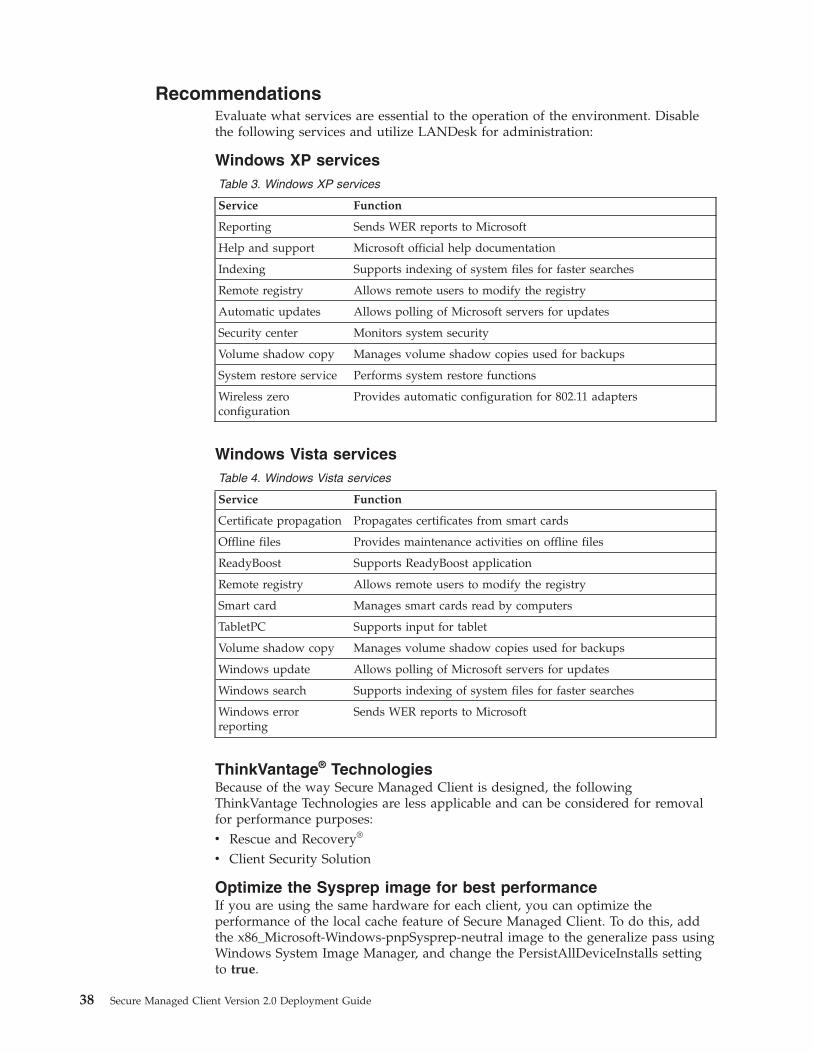
RecommendationsEvaluate what services are essential to the operation of the environment. Disablethe following services and utilize LANDesk for administration:
Windows XP servicesTable 3. Windows XP services
Service Function
Reporting Sends WER reports to Microsoft
Help and support Microsoft official help documentation
Indexing Supports indexing of system files for faster searches
Remote registry Allows remote users to modify the registry
Automatic updates Allows polling of Microsoft servers for updates
Security center Monitors system security
Volume shadow copy Manages volume shadow copies used for backups
System restore service Performs system restore functions
Wireless zeroconfiguration
Provides automatic configuration for 802.11 adapters
Windows Vista servicesTable 4. Windows Vista services
Service Function
Certificate propagation Propagates certificates from smart cards
Offline files Provides maintenance activities on offline files
ReadyBoost Supports ReadyBoost application
Remote registry Allows remote users to modify the registry
Smart card Manages smart cards read by computers
TabletPC Supports input for tablet
Volume shadow copy Manages volume shadow copies used for backups
Windows update Allows polling of Microsoft servers for updates
Windows search Supports indexing of system files for faster searches
Windows errorreporting
Sends WER reports to Microsoft
ThinkVantage® TechnologiesBecause of the way Secure Managed Client is designed, the followingThinkVantage Technologies are less applicable and can be considered for removalfor performance purposes:v Rescue and Recovery®
v Client Security Solution
Optimize the Sysprep image for best performanceIf you are using the same hardware for each client, you can optimize theperformance of the local cache feature of Secure Managed Client. To do this, addthe x86_Microsoft-Windows-pnpSysprep-neutral image to the generalize pass usingWindows System Image Manager, and change the PersistAllDeviceInstalls settingto true.
38 Secure Managed Client Version 2.0 Deployment Guide
The sample entry for the .xml file is shown below:<settings pass="generalize">
<component name="Microsoft-Windows-PnpSysprep" processorArchitecture="x86"publicKeyToken="31bf3856ad364e35" language="neutral" versionScope="nonSxS"xmlns:wcm="http://schemas.microsoft.com/WMIConfig/2002/State" xmlns:xsi="http://www.w3.org/2001/XMLSchema-instance"
<PersistAllDeviceInstalls>true</PersistAllDeviceInstalls></component></settings
Improving Vista performanceSome Vista services can be disabled to improve Vista performance.
Note: The services on this list are suggestions only. Make sure that you don’t needany of these services before you disable them.v SERVICES
– Volume Shadow Service– Windows Update– Windows Search– SuperFetch– ReadyBoost– Tablet PC Service
v MSCONFIG
– Google Updater
Roaming user profiles and folder redirectionRoaming profiles allow the user to have the same working environment no matterwhat computer they log on to, by storing the profiles on the NAS server. The firsttime that a user logs in after roaming profiles have been enabled, a roaming profiledoes not exist for the user, so Windows uses the profile that’s stored in the localC:\Documents and Settings\ folder. When the user logs off, the entire contents ofthe local profile (minus the Internet Explorer cache) is copied to the server. If theuser has a lot of big files, this process can take a long time to complete.
Note: If you want to configure a portion of your storage array as network attachedstorage, see Chapter 8, “Setting up network shares,” on page 49.
To prevent performance issues, use folder redirection. This allows you to saveportions of the user’s profile in a different location on the network than theroaming profile. The advantage to using folder redirection is that once a folder hasbeen redirected to an alternate location, it no longer has to be copied every timethat the user logs on or off. The folders that you can redirect are:v Application Datav Desktopv My Documentsv Start Menu
For more information on creating a roaming user profile, see http://technet.microsoft.com. For implementation and best practices information seehttp://technet.microsoft.com.
Here is a list of terms you can search for:
Chapter 6. Secure Managed Client image creation and tuning 39

v How to create a roaming user profilev How to configure a user account to create a roaming user profilev Creating a share folder to store a roaming user profilev Implementing a roaming user profilev User profiles and folder redirectionv Configuring folder redirectionv Implementing folder redirection
Note: Using user profiles and folder redirection is a good way to allow the user tosave files in a pristine image environment. The user profiles and folder redirectionmust be set up before marking an image as pristine. Any files saved to a networkshare will not be deleted when a pristine image is rebooted.
40 Secure Managed Client Version 2.0 Deployment Guide
Chapter 7. Populating a base image
All new user images must be created from a base image. If the base image containsa valid Sysprep image, deploying a new user is a straightforward process. If thebase image is blank allocated space, each new user will also receive blank space.Although this is valid, it does not utilize the full power of the Secure ManagedClient solution.
This section discusses the main methods to deploy or install the base image ontothe storage array for future creation of new users.
Using bootable CD/DVD mediaThis method is used to boot the client to the ULOS, connect the client to the baseimage on the storage array, and boot the media to install the desired image. Thebootable media can be a DVD containing an ImageX image or Ghost image, a setof Recovery CDs, or an operating system installation CD. However, if networkaccess is required, use the SMCWinPE.iso CD provided in the LANDeskinstallation package. The SMCWinPE.iso is a Windows PE CD that contains thenetwork drivers needed to connect to the network from a client device. ThisWindows PE CD also contains a graphical user interface (GUI) that enables thecontents of the local drive on the local physical hard disk drive to be copied to thebase image.
Notes:
1. ImageX is a command-line tool that captures, modifies, and applies installationimages for deployment in a manufacturing or corporate environment. ImageXdoes not do a sector-by-sector copy. This results in a much smaller image filethan other clone tools such as Ghost.
2. Ghost is an image tool that clones a hard disk drive using sector-by-sectorcopying.
You can use any device that you would normally use to deploy an operatingsystem image. The image can be located on a set of DVDs, a network share, or thelocal physical hard disk drive.
To deploy the desired image, complete the following steps:1. Create a new base image (see Chapter 6, “Secure Managed Client image
creation and tuning,” on page 23. Determine how much space this image willrequire. The new image appears in the Pending folder. Do not activate thisimage until you have confirmed this image is ready to create new users.
2. Insert the bootable media and boot the client to the ULOS. Do not enter anycredentials at this point.
3. From the Network view, expand the appropriate LANDesk core. Select Devices-> All Devices. Match up the name on the list to the serial number which isusually found on the outside of the box.
4. Drag the device over to the new pending base image that was just created.5. A Boot SMC Client dialog box appears. Make sure that Include CDROM in
boot order is checked and click Boot.6. The client ULOS disappears, connects to the blank base image on the storage
array, and begins booting to the media.
© Copyright Lenovo 2009, 20010 41
7. Deploy the base image. If you are using the SMCWinPE CD, use the GUI tocopy the contents to the physical drive to the storage array, or open acommand prompt and run any imaging tools. Any changes made to the harddisk drive would be made to the base image space located on the storage array.
SMCWinPE.isoThe SMCWinPE.iso file is located in the ldmain share of the LANDesk installation,under the tcm\dist directory.
Connecting to a target image LUN on an SMC Storage Arrayusing the iSCSI Initiator
This section describes how to use the iSCSI initiator program to connect to aspecific target location on the Secure Managed Client Storage Array. The iSCSIinitiator program is installed by default on Microsoft Vista and can be downloadedfor both XP and Windows Server 2003. This process is useful for copying imagesdirectly to the space using tools such as imagex or xcopy, modifying an image thatalready exists, or browsing the directory structure on the storage array for theimage you are connecting. You can connect to a base image, but only in PendingState. You can also connect to any user image as long as it is not in use. Here is ascenario for performing this process:1. Start the iSCSI Initiator program.2. Rename the initiator by clicking the Change... button. You can get this
information by right-clicking on the SMC Storage Array that is provisioned inthe Core Console and clicking on Properties to open the Image Propertieswindow. The Base image must be Pending Image and not Active Image in theType field to see the Chap Secret. Paste that information in the field and clickOK.
3. Click the Secret button on the General tab of the iSCSI initiator program.Copy and paste the Chap Secret into that field and click OK.
4. Click the Discovery tab in the iSCSI Initiator Properties window and thenclick Add Portal.... Add the IP address of your SMC Storage Array in the fieldand click OK to close the window.
5. Click on the Targets tab. You should see a listing of about 5 targets. ClickRefresh to ensure that you have the latest targets listed. Highlight the entrythat includes the name of the space you are connecting to on the SMC StorageArray. Click Log on... to open the Log On to Target window.
6. Click Advanced... . The Advanced Settings window opens.7. Check the CHAP logon information box. Copy the information from the
Initiator User and Chap Secret fields on the Image Properties screen in step 2and paste this information in the User name: and Target secret: fields. ClickOK.
8. You will now see that drive as Connected. You are now ready to prepare thedrive for an image.
9. Open a DOS command prompt and type in the following commands:
Note: Make sure you select the right disk for the next step. The cleancommand will erase the disk completely. You can run list disk or DiskManagement to check that the disk is erased completely.a. diskpart – this will open a > prompt.b. list disk – scan all disks listed for the appropriate disk to prepare.
42 Secure Managed Client Version 2.0 Deployment Guide

c. select disk 1 – (where 1 (or appropriate) is the appropriate disk you areconnected to based on steps above. The xize of the disk is a goodparameter to use to ensure you will be preparing the correct disk withdiskpart.
d. clean – will wipe the selected disk of all data.e. create partition primary – will create a primary partition.f. active – will make the partition an active partition.g. assign - will assign next drive letter available.h. exit - will return you to a standard command prompt.i. format X: /fs:NTFS /q /y where – X: is the letter of the drive that was
assigned in step 9g.10. Update Boot Sector if needed. If you are applying an XP .wim file from an XP
system, or you are applying a Vista .wim file from a Vista system, no updateis needed. However, if you are trying to apply an XP WIM from Vista, or aVista WIM from XP, then you need to also run the BOOTSECT.EXE commandto adjust the boot sector. To apply an XP WIM, you would run thebootsect.exe /nt52 X: command. To apply a Vista .wim file, you would run thebootsect.exe /nt60 X: command.
11. Apply a wim image with the following commandimagex.exe /apply foo.wim 1 x:\
12. Disconnect the iSCSI Initiator from the LUN by clicking on the target that isconnected and clicking the Details button. Check the box next to the identifierand click Log off.... Make sure that you have closed all Windows Explorerwindows or command prompts that may be connected to the drive you justprepared.
Copying a multiple partition image to the storage array,version 1.x
Many organizations utilize multiple partitions within their PC image. In mostcases, the first partition is the Windows partition and the second is a redirecteddata partition for storing user data. To allow for these multiple partitions to becopied from the local hard disk of a Secure Managed Client client to the storagearray, do the following:1. Create the base image on the storage array using the Secure Managed Client
Management Console. That image will be in Pending state.2. Start the client with the image sysprepped to the hard drive to the ULOS
screen.3. Insert your Secure Managed Client WinPE CD into the CD-ROM drive on the
client.4. In the Secure Managed Client Management Console, left-click, hold and drag
the client machine to the base image in pending state. For example, drag aclient named LENOVO-L3A0426 down to the Test Base Image.
5. The Boot SMC Client window opens. Select include cd-rom in the boot orderat the bottom of the window.
6. Click Boot.7. After several seconds, the client will restart and boot from the CD. Windows
PE will load and a wizard will start. This allows the client to be connected tothe storage array Pending image space you created in step 1 to allow forplacing an operating system in that space.
8. Click Next and then choose the Command Line option from the wizard. Acommand prompt will open.
Chapter 7. Populating a base image 43

9. Type diskpart. This will start the diskpart command line application10. Type list volumes. This will list all the volumes that diskpart sees.
You should see three volumes:a. C: this is your operating system volume from your local hard drive on
your client.b. D: this is the data volume from your local hard drive on your SMC client.c. RAW volume: the storage array Base Image created in step 1 on page 43.
11. Type list disk. You should see disk 0 (local hard drive) and disk 1 the storagearray Base Image created in step 1 on page 43)
12. Type select disk 1. This will select the storage array Base Image created in step1 on page 43.
13. Type Create partition primary size=n where n is the size of the operating systempartition to create in the Base Image. This will create the operating systempartition within the Base Image.
14. Type Create partition extended. This will create the extended data partition withthe space left in disk 1.
15. Type Create partition logical. This will specify that data partition into a logicalpartition
16. Type Format fs=ntfs label=”data” quick. This will format disk 1 as NTFS.17. Type Assign letter=g. This will assign a temporary drive letter to the data
partition.18. Type xcopy d:\ g:\ /s /h /e /y /q. This will copy all data from the d: drive on
your local hard drive to the data partition on the storage array in the BaseImage space. This will take several minutes since it is a binary copy of all dataon your d: drive.
19. When you finish, click the Restart Wizard button. This will restart the wizardto allow for a copy of the c: drive
20. Click on select local drive.21. Select the C: partition.22. Select Disk 1 to copy to.23. Check box to select partition on disk 1.24. Check partition 1 where the operating system partition should go.25. Click Next. This process will take some time to complete.26. When finished, your image is ready.
Copying a multiple partition image to the storage array,Version 2.0
To allow for these multiple partitions to be copied from the local hard disk of aSecure Managed Client client to the storage array for Version 2.0, do the following:1. Create the base image on the storage array using the Secure Managed Client
Management Console. That image will be in Pending state.2. Start the client with the image sysprepped to the hard drive to the ULOS
screen.3. Insert your own WinPE cd into the CD drive on the client.4. In the Secure Managed Client Management Console, left-click, hold and drag
the client machine to the base image in pending state. For example, drag aclient named LENOVO-L3A0426 down to the Test Base Image.
5. The Boot SMC Client window opens. Select include cd-rom in the boot orderat the bottom of the window.
44 Secure Managed Client Version 2.0 Deployment Guide
6. Click Boot.7. After several seconds, the client will restart and boot from the CD. Windows
PE will load and a wizard will start. This allows the client to be connected tothe storage array Pending image space you created in step 1 on page 43 toallow for placing an operating system in that space.
8. Click Copy image from a specific location and click Next.9. This window displays how many partitions are on the local drive. It also
shows the CD_ROM if you chose the copy the CD-ROM to the user storagearray option. Click Next.
10. Select the destination for the image from when you click on the last partitionin Step 9. If you are running Windows Vista, you want to check the optionThis is the last partition of a multi-partitioned Vista system to be copied ifthis is the last partition you are copying. Click Next. The image starts to copy.
11. On the Confirmation page, click Next.12. The image (partition) will be copied. Click Restart if you have more partitions
to copy, otherwise click Reboot.
Note: If you have multi-partition Vista, you must click the box as described inStep 9 or the target drive might not be bootable.
Deploying the image directly to the storage arrayUsing this method, you connect directly to the base image on the storage arraywithout using the client. Use this method only if there is an image file available forinstallation to a hard disk drive and if you are familiar with using an iSCSIinitiator. An iSCSI initiator is included with Windows Vista or it can bedownloaded for XP from the following Web address:http://www.microsoft.com/iscsi/
Note: Installation from a set of installation media or a physical hard disk driveshould use “Using bootable CD/DVD media” on page 41.
To deploy the desired image, complete the following steps:1. Determine how much space this image will require and create a new base
image. The new image appears in the Pending folder. Do not activate thisimage until you have confirmed that this image is ready to create new users.
2. From the LANDesk console, right click on the base image and select Properties.An Image Properties dialog box appears. You will need the followinginformation:v ISCSI Initiatorv Initiator Userv Chap Secretv Target
3. Go to the system that has an iSCSI initiator capable of connecting to the storagearray’s IP address.
4. Change the settings of the system initiator to match the Initiator Name, User,and Chap Secret information.
5. Perform a discovery on the storage array’s IP address. This address can beobtained from the Target information.
6. The discovery should return a target that matches the Target name notedabove. If it does not, the iSCSI initiator settings were not entered correctly.
Chapter 7. Populating a base image 45

7. Log on to the iSCSI target. The initiator should create a new disk on yoursystem.
8. Follow the steps to deploy the base image to a disk.9. Log off of the iSCSI target.
Once there are valid base images uploaded to the storage array, follow theinstructions to create a new user in the LANDesk console.
Boot accelerationUsing boot acceleration, the storage array has the capability to map records used atboot for each LUN to records used at boot by a master image.
Since the storage array processes the data for boot acceleration from a normal boot,it should not be enabled until after most users have gone through the initial bootsequences that sets up the deployed image. The sequence of steps should normallybe:1. Deploy the image that the users will be predominantly using through
LANDesk.2. Create the users and propagate the image to their volumes through LANDesk.3. Go through the initial boots for a majority of the users.4. Enable boot acceleration through the LANDesk GUI.
a. Select the <storage array name> and properties −> boot acceleration
b. Enable boot acceleration for the base image.
LANDesk will enable boot acceleration for all of the images that were derivedfrom that base.
5. Boot one user before booting the others. This LUN will now have its bootrecords permanently moved into cache.
6. Boot all of the users in groups of approximately 30 at a time. During this stepthe data for their boot sequences will be gathered and can be analyzed. Afterthe data is processed by the storage array, the mapping of this volume’s bootrecords to the boot records of the master volume will be stored in the storagearray. During subsequent boots those records will be served from the bootcache and will speed up boots for all the volumes that are running with bootacceleration.
Hints and tipsWhen using the SMCWinPE.iso CD, be aware of the following:v Ensure that the client system boots to the ULOS before booting to the CD. If the
CD boots before the ULOS, the system will not connect to the storage array.v When opening the command prompt, the focus is still on the completion
window and hitting Enter reboots the machine (the Completion window statesthis).
v During the initialization process, when booting the SMCWinPE.iso CD, theInitialization screen disappears for a few seconds and then returns with adisplay size change.
v Disconnect the hard disk drive on the first boot after installing the new image(the Confirmation window states this).
v When copying an image from a CD, swap the CD to a copy at the confirmationwindow before pressing Enter (the Confirmation window states this).
46 Secure Managed Client Version 2.0 Deployment Guide

v A log file that logs the results of the SMCWinPE.iso installation is stored on thedestination location in smccopy.log.
v The SMCWinPE.iso CD is not meant to copy service partition data to the storagearray. Instead, the SMCWinPE.iso copies data to a normal bootable drive, usuallythe C drive.
If not using a Lenovo CDAny bootable CD/DVD media can be used to boot a client. USB media, includingUSB keys or USB hard disk drives, can not be used if the storage array access isalso required. If using a bootable CD, be aware of the following information:v Make sure the client system boots to the ULOS before booting to the CD. If the
CD boots before the ULOS, that system will not be able to connect to the storagearray’s disk image.
v If the CD reboots, the client must boot back to the ULOS before booting to theCD again.
v When installing Windows XP in text mode, messages from the boot managerappear on the screen. They will disappear when you boot into graphics mode.
Chapter 7. Populating a base image 47

48 Secure Managed Client Version 2.0 Deployment Guide

Chapter 8. Setting up network shares
The storage array can be configured as a Network Attached Storage (NAS) device. Toconfigure, do the following:1. Configure Active Directory®:
a. Make sure that Active Directory has been configured in the DirectoryManager. See “Secure Managed Client / LANDesk setup” on page 13 formore information.
Note: NAS volumes can be created without Active Directory configuration.However, Active Directory must be configured in order to manage thesevolumes using AD permisssions and policies.
b. From the SMC Manager screen, right-click on the NAS volume in thestorage array and click Active Directory configuration. The ActiveDirectory selection screen opens.
c. Click on the drop-down menu and click on the Active Directory domainthat you want to configure the NAS volume with.
d. Click Select.2. Create a NAS Volume:
a. Right-click on the NAS entry in the storage array and click New NASvolume. The Create network storage screen opens.
b. Enter the volume name. Note that this must be all lower case. Select volumesize (in GB).
c. Click Create. You will now see the new volume. By default, SMC creates anew share by the same name as the volume.
3. NAS permissions and policies:a. Right-click on network share and click Unlock NAS share.b. Configure the Active Directory permissions and policies from the Active
Directory server.c. Right-click on network share again and click Lock NAS Share.By default, the default permissions for the shares are Read Access Only. Tochange:a. Right-click on the share and select Unlock NAS Share. An SMC Manager
warning will pop up informing you that unlocking the NAS share willallow all authenticated users full access.
b. Click OK.Go into Active Directory to configure the ACL shares. Then right click on theshares again and click Lock NAS Shares. The Active Directory configurationnow has access rights over the shares.
4. NAS share deletion:a. To delete a NAS share or volume, right click on the share and click Delete
NAS share/volume.
You can create other new shares as well as volumes:1. Right-click on the volume. The Create Network Share window opens.2. Enter the share name and description, if desired.3. Click Create.
© Copyright Lenovo 2009, 20010 49

50 Secure Managed Client Version 2.0 Deployment Guide
Chapter 9. Configuring synchronous and asynchronousreplication
This chapter shows you how to create synchronous and asynchronous replicationand promote the secondary storage array to become the primary in the case of aproblem. It also discusses the use of asynchronous replication
Replication allows for disaster recovery by using more than one storage array; oneis used as a primary and the other is used as a secondary or backup array.
Synchronous replication provides real-time backup. Because of this the backupstorage array needs to be in close proximity to the primary storage array.
Asynchronous replication utilizes snapshots. This type of replication can beconfigured to only occur at scheduled intervals. By scheduling backups, thesecondary storage array can be located off-site.
PrerequisitesThese are the prerequisites for synchronous and asynchronous replication:v Both the primary and secondary storage arrays must have synchronous
replication licenses installed.v The secondary storage array must have storage equal to or greater than the
primary storage array. See Chapter 4, “Secure Managed Client specificinstallation,” on page 9 for more information.
v The secondary storage array must be provisioned by the LANDesk console.v The secondary storage array must not have any base images, user volumes or
NAS shares installed.v Replication requires additional licensing. See “License upgrades” on page 17
Creating synchronous replication
To create synchronous replication do the following:1. Right-click on the primary storage array and click Configure replication. The
Configure replication window opens.2. From the Replication mode drop-down, select Synchronous. SMC Manager will
list available storage arrays suitable for synchronous replication.3. Select the storage array that is to be secondary and click Synchronize.4. After the configuration is complete, the secondary storage array will be listed
under the primary storage array in the SMC Manager.
Note: Even though the link between the two arrays is complete, thesynchronous replication operation can continue for some time depending onthe number of user volumes that are already created on the primary storagearray.
© Copyright Lenovo 2009, 20010 51

Creating asynchronous replicationTo create asynchronous replication do the following:1. Right-click on the primary storage array and click Configure replication.2. From the Replication mode drop-down, select Snap-assisted. SMC Manager will
list available storage arrays suitable for asynchronous replication.3. To use the default backup schedule, select the storage array that is to be
secondary and click Synchronize.4. To configure a custom backup schedule, click Advanced, edit the fields as
desired, and click Synchronize
5. After the configuration is complete, the secondary storage array will be listedunder the primary storage array.
Note: Even though the link between the two arrays is complete, theasynchronous replication operation can continue for some time depending onthe number of user volumes that are already created on the primary storagearray.
Manual failoverIn the event of a problem with the primary storage array, you can promote thesecondary array to become the primary array.
To promote the secondary array, do the following:1. Right-click on the secondary storage array and click Promote to Primary
2. After the process completes, the secondary storage array is now the primary.The original primary array is no longer provisioned and is removed from thestorage array tree.
3. Reset the DHCP root path to point to the new primary storage array.4. The original storage array can now be re-provisioned and configured as a
secondary storage array using the steps shown in “Creating synchronousreplication” on page 51.
Note: Before you promote the secondary array, you should check the status ofthe replication. Right-click on the secondary array entry under the primaryarray in the SMC Manager and select Replication status. The replicationprogress window will be displayed showing the overall replication progress aswell as the progress of each image. If the secondary array is promoted beforereplication is complete, some images may not be available on the secondaryarray once it is promoted.
52 Secure Managed Client Version 2.0 Deployment Guide

Chapter 10. Troubleshooting
This chapter contains information on troubleshooting, network failure points, andlimitations you may encounter when configuring and testing Secure ManagedClient. See the Secure Managed Client - Storage Array User Guide for additionaltroubleshooting information.
ProblemsThis section contains various problems you may encounter and suggestions onhow to fix them.
Storage array diagnosticsOne way to check that the storage array is functioning efficiently is to watch the 12green lights on the front. If many of them are green, the storage array is runningefficiently. If most of them are not lit, the storage array is saturated.
the lights go off when the drives are being written to. Therefore if the lights aresteadily off, the storage array is saturated and most likely not running efficiently. Ifthe lights are steadily on or flickering, the storage array has not reached saturation.
Secure Managed Client will not bootIf you get a boot error that says No iSCSI Boot port available, make sure that youhave set iSCSI to primary. See “Secure Managed Client manual setup” on page 10for more information.
If the BIOS cannot connect to the storage array and boot the D0 and ULOS image,you will see an error message. Do not retry the boot sequence. Instead, pressCtrl-Alt-Del to force the BIOS to retry to connect to the storage array. If this fails,either the network or the storage array has failed.
When the system connects to the storage array and begins booting, the SecureManaged Client screen appears. If the splash screen disappears and a black screenappears, the LANDesk agent in D0 is attempting to connecting to the LANDeskcore server. Either the core server or the network connection has failed.
If the system can boot D0 and boot ULOS, the network and storage array areworking properly. If your Windows image cannot boot, follow the prompts fromthe LANDesk ULOS error.
Clients will not boot after moving the Management ConsoleIf you can not get the clients to boot after moving the Secure Managed ClientManagement Console, make sure you update the core configuration/informationon the storage array. Perform these steps:1. Open the Secure Managed Client console, right click on the storage array and
select Install Boot Image.2. Enter the required information:
share \\<localhost name/IP\ldmainuser <admiinistrator group user on the box>password
3. Select Authenticate
© Copyright Lenovo 2009, 20010 53
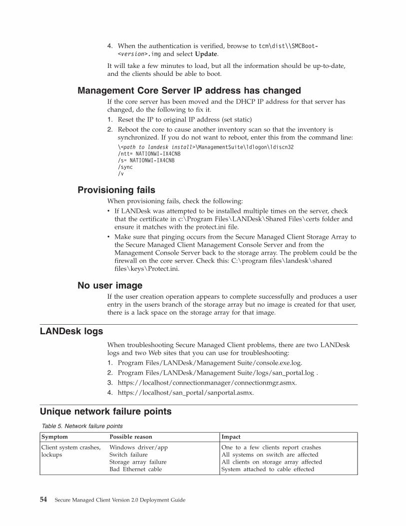
4. When the authentication is verified, browse to tcm\dist\\SMCBoot-<version>.img and select Update.
It will take a few minutes to load, but all the information should be up-to-date,and the clients should be able to boot.
Management Core Server IP address has changedIf the core server has been moved and the DHCP IP address for that server haschanged, do the following to fix it.1. Reset the IP to original IP address (set static)2. Reboot the core to cause another inventory scan so that the inventory is
synchronized. If you do not want to reboot, enter this from the command line:\<path to landesk install>\ManagementSuite\ldlogon\ldiscn32/ntt= NATIONWI-IX4CN8/s= NATIONWI-IX4CN8/sync/v
Provisioning failsWhen provisioning fails, check the following:v If LANDesk was attempted to be installed multiple times on the server, check
that the certificate in c:\Program Files\LANDesk\Shared Files\certs folder andensure it matches with the protect.ini file.
v Make sure that pinging occurs from the Secure Managed Client Storage Array tothe Secure Managed Client Management Console Server and from theManagement Console Server back to the storage array. The problem could be thefirewall on the core server. Check this: C:\program files\landesk\sharedfiles\keys\Protect.ini.
No user imageIf the user creation operation appears to complete successfully and produces a userentry in the users branch of the storage array but no image is created for that user,there is a lack space on the storage array for that image.
LANDesk logsWhen troubleshooting Secure Managed Client problems, there are two LANDesklogs and two Web sites that you can use for troubleshooting:1. Program Files/LANDesk/Management Suite/console.exe.log.2. Program Files/LANDesk/Management Suite/logs/san_portal.log .3. https://localhost/connectionmanager/connectionmgr.asmx.4. https://localhost/san_portal/sanportal.asmx.
Unique network failure pointsTable 5. Network failure points
Symptom Possible reason Impact
Client system crashes,lockups
Windows driver/appSwitch failureStorage array failureBad Ethernet cable
One to a few clients report crashesAll systems on switch are affectedAll clients on storage array affectedSystem attached to cable effected
54 Secure Managed Client Version 2.0 Deployment Guide

Table 5. Network failure points (continued)
Symptom Possible reason Impact
Clients report data loss Windows corruptionSwitch failureStorage array failureBad Ethernet cable
One client has corrupted diskAll systems on switch have packet/data lossAll clients on storage array affectedSystem attached to cable affected
Clients can boot toULOS but are unable toboot windows
Windows corruptionLDMS failureActive Directory failure
One client has corrupted diskAll clients report a time-out dialogClients get a dialog about login
Clients are unable toboot to ULOS
CMOS setupSwitch failureStorage array failureEthernet cableLDMS failureDHCP server failure
One to a few clients report boot issuesAll systems on switch are affectedAll clients on storage array affectedSystem attached to cable affectedAll clients report a time-out dialogAll systems on subnet are affected
Web surfing issues DNS serverSwitch failure
All systems using DNS ServerMultiple users report Web issues
Binding order in the Secure Managed Client environmentYou can change the order in which the network adapters are displayed in theAdvanced Settings window. If you want to have the Local Area Connectionadapters displayed before the Remote Access Connections adapter, run one of thefollowing procedures:
Changing the binding order for Windows XPTo change the primary binding order for Windows XP, do the following:1. Open a DOS Command prompt.2. Type ipconfing and press Enter. You will typically see a Local Area Connection
entry and Local Area Connection 2 entry with an IP address.3. Type ncpa.cpl then press Enter. The Network Connections window opens.4. On the Network Connections window, click Advanced -> Advanced Settings.
The Advanced Settings window opens.5. Select the Adapters and Bindings tab.6. In the Connections box, move the Local Area Connection entry that has an IP
address of 172.30.0.2 to the bottom of the list, if it is not on the bottom of theConnections list already.
7. Shut down and restart your system.
Changing the binding order for Windows VistaTo change the primary binding order for Windows Vista, do the following:1. Open an elevated DOS Command prompt.2. Type ipconfing and press Enter. You will typically see a Local Area Connection
entry and Local Area Connection 2 entry with an IP address.3. Click Start -> Run .4. Type ncpa.cpl then click OK. The Network Connections window opens.5. On the Network Connections window, click Advanced -> Advanced Settings.
The Advanced Settings window opens.6. Select the Adapters and Bindings tab.
Chapter 10. Troubleshooting 55

Note: Some users may need to press the Alt key to display this menu.7. In the Connections box, move the Local Area Connection entry that has an IP
address of 172.30.0.2 to the bottom of the list, if it is not on the bottom of theConnections list already.
8. Shut down and restart your system.
Limitationsv Hibernation over LAN is not supported.v After updating the BIOS to the latest version on an ThinkCentre M57p eco client,
the SMCBoot option is not available in Network Devices. In this case, theThinkCentre M57p eco client was probably purchased before Secure ManagedClient development began. The NIC firmware in this system needs to beupdated to support the iSCSI boot that Secure Managed Client requires. Pleaserefer to the Secure Managed Client support Web site for more information aboutdownloading this utility.
v The SMCWinPE CD is only meant to copy service partition data to the normalbootable drive.
v Using the SMC WinPE CD, the Lenovo Service Partition is not copied to theuser’s image on the storage array. The Secure Managed Client WinPE CD wasonly designed to copy a single user partition, not an entire hard drive. To copythe service partition, do the following:1. Clean the image on the storage array.2. Create the service partition on LUN [ diskpart -> create partition primary
size=6131 ].3. Create the system partition on LUN [ diskpart -> create partition primary ].4. Set system partition as active.5. Copy the service partition from the local HDD to the LUN.6. Copy the system partition from the local HDD to the LUN.7. Remove the local hard disk drive.8. Set the service partition label to SERVICEV002.9. Hide the service partition [ set id=27 ].
10. Set the system partition label to SW_Preload.11. Boot to the desktop and uninstall Rescue and Recovery.12. Reinstall Rescue and Recovery.
v Recovery CDs booted on a client with a physical hard disk drive will restore tothe physical hard disk drive instead of the image on the storage array. RecoveryCDs always restore to Disk 0. With a physical hard disk drive in the system, thatdrive is Disk 0 and the storage array drive is Disk 1. Remove the local physicalhard disk drive before using a set of preload recovery CDs.
v Secure Managed Client does not fix any problems cloning Microsoft images. Anyissues or problems cloning Windows images will still be present when cloningwith Secure Managed Client.
v The Windows system clock will delay about 3 seconds within 24 hours over anormal workload. The Secure Managed Client boot manager uses system clockcycles and may delay the Windows system clock with higher workloads. Use theautomatic feature of Windows to sync the clock to an internet time server.
v Remote Assistance may not be able to connect to the desired system. The clientuses two NICs in Windows. One is for communication on the regular networkand one is for communication to the Secure Managed Client boot manager.
56 Secure Managed Client Version 2.0 Deployment Guide

These two NICs can cause problems with Remote Assistance and the IP addresslisted in the invitation. Disable the second LAN while creating the RemoteAssistance invitation.
v If the CSS or SafeGuard Easy GINA is installed in Windows XP, the SecureManaged Client single sign-on feature does not work. The user must log in toWindows again using the GINA that is installed in Windows.
v LANDesk console does not display an error message indicating insufficientspace on the storage array.
v The first boot of all 100 systems is significantly slow due to Windows PnP for all100 systems. Booting all 100 systems at the same time produces a great deal ofdisk I/O on the storage array. Boot the systems for the first time in groups of 30or less.
v When using the Secure Managed Client WinPE CD to copy the local hard diskdrive partition to the storage array, the user must unplug the physical drivebefore rebooting. Unplug the local physical hard drive before booting to theuser’s image on the storage array.
v Windows XP installation hang and black screen or reboot occurs duringinstalling F5 installation of Windows XP. The client only supports the defaultHAL when installing Windows XP or Windows Vista (ACPI multiprocessor PCHAL).
Chapter 10. Troubleshooting 57

58 Secure Managed Client Version 2.0 Deployment Guide

Appendix. Notices
Lenovo may not offer the products, services, or features discussed in thisdocument in all countries. Consult your local Lenovo representative forinformation on the products and services currently available in your area. Anyreference to an Lenovo product, program, or service is not intended to state orimply that only that Lenovo product, program, or service may be used. Anyfunctionally equivalent product, program, or service that does not infringe anyLenovo intellectual property right may be used instead. However, it is the user’sresponsibility to evaluate and verify the operation of any other product, program,or service.
Lenovo may have patents or pending patent applications covering subject matterdescribed in this document. The furnishing of this document does not give youany license to these patents. You can send license inquiries, in writing, to:
Lenovo (United States), Inc1009 Think PlaceBuilding OneMorrisville, NC 27560USAAttention: Lenovo Director of Licensing
LENOVO GROUP LTD. PROVIDES THIS PUBLICATION “AS IS” WITHOUTWARRANTY OF ANY KIND, EITHER EXPRESS OR IMPLIED, INCLUDING, BUTNOT LIMITED TO, THE IMPLIED WARRANTIES OF NON-INFRINGEMENT,MERCHANTABILITY OR FITNESS FOR A PARTICULAR PURPOSE. Somejurisdictions do not allow disclaimer of express or implied warranties in certaintransactions, therefore, this statement may not apply to you.
This information could include technical inaccuracies or typographical errors.Changes are periodically made to the information herein; these changes will beincorporated in new editions of the publication. Lenovo may make improvementsand/or changes in the product(s) and/or the program(s) described in thispublication at any time without notice.
The products described in this document are not intended for use in implantationor other life support applications where malfunction may result in injury or deathto persons. The information contained in this document does not affect or changeLenovo product specifications or warranties. Nothing in this document shalloperate as an express or implied license or indemnity under the intellectualproperty rights of Lenovo or third parties. All information contained in thisdocument was obtained in specific environments and is presented as anillustration. The result obtained in other operating environments may vary.
Lenovo may use or distribute any of the information you supply in any way itbelieves appropriate without incurring any obligation to you.
Any references in this publication to non-Lenovo Web sites are provided forconvenience only and do not in any manner serve as an endorsement of those Websites. The materials at those Web sites are not part of the materials for this Lenovoproduct, and use of those Web sites is at your own risk.
© Copyright Lenovo 2009, 20010 59

Any performance data contained herein was determined in a controlledenvironment. Therefore, the result in other operating environments may varysignificantly. Some measurements may have been made on development-levelsystems and there is no guarantee that these measurements will be the same ongenerally available systems. Furthermore, some measurements may have beenestimated through extrapolation. Actual results may vary. Users of this documentshould verify the applicable data for their specific environment.
TrademarksThe following terms are trademarks of Lenovo in the United States, othercountries, or both:
LenovoLenovo logoThinkCentre
Intel and Intel vPro are trademarks or registered trademarks of Intel Corporationor its subsidiaries in the United States and other countries.
Microsoft, Windows Server, Windows Vista and Windows are trademarks ofMicrosoft Corporation in the United States, other countries, or both.
Linux is a registered trademark of Linus Torvalds in the United States, othercountries, or both.
Other company, product, or service names may be trademarks or service marks ofothers.
60 Secure Managed Client Version 2.0 Deployment Guide

Glossary
Advanced Host Controller Interface (AHCI). Anapplication programming interface defined by Intelwhich defines the operation of Serial ATA host busadapters in a non-implementation-specific manner,
BitLocker. BitLocker Drive Encryption is a full diskencryption feature included with Microsoft WindowsVista Ultimate. It is designed to protect data byproviding encryption for entire volumes.
Dynamic Host Configuration Protocol (DHCP) . TheDynamic Host Configuration Protocol is a computernetworking protocol used by DHCP clients to retrieveIP address assignments and other configurationinformation.
ISCSI. A protocol that allows clients (called initiators)to send SCSI commands to SCSI storage devices(targets) on remote servers. This allows organizations toconsolidate storage into data center storage arrayswhile providing hosts with the illusion oflocally-attached disks
Logical Unit Number (LUN). In an iSCSIenvironment, LUNs are essentially numbered disk
drives. An initiator negotiates with a target to establishconnectivity to a LUN; the result is an iSCSI sessionthat emulates a SCSI hard disk.
Pristine image. The Pristine image is a feature thatallows you to purge any user changes or applicationsmade to the image. Once marked as pristine, the imageconfigured image will always stay locked from anymodification If needed, you can remove the pristinelock which allows you or users to make modificationsto the image.
Storage array. An appliance where the SecureManaged Client client’s data is securely stored. Allconfigurations have 12 disk and 6 x 1GB Ethernet ports.The Storage Array is managed and provisionedremotely through the SMC Management Console.
ULOS. The Secure Managed Client User Logon Screen
VNIF. Virtual Network Interface
© Copyright Lenovo 2009, 20010 61

62 Secure Managed Client Version 2.0 Deployment Guide


Printed in USA