Embed Size (px)
Citation preview
(i)
NATIONAL INSTRUCTIONALMEDIA INSTITUTE, CHENNAI
FITTER
SECTOR: Production & Manufacturing
TRADE THEORY
Post Box No. 3142, CTI Campus, Guindy, Chennai - 600 032
4th Semester
NSQF LEVEL - 5
DIRECTORATE GENERAL OF TRAININGMINISTRY OF SKILL DEVELOPMENT & ENTREPRENEURSHIP
GOVERNMENT OF INDIA
Copyrigh
t @ NIM
I
Not to be Republish
ed
(ii)
Sector : Production & ManufacturingDuration : 2 - YearsTrade : Fitter 4th Semester - Trade Theory
Copyright@2018 National Instructional Media Institute, Chennai
First Edition : October 2018 Copies : 1,000
Rs. 210/-
All rights reserved.
No part of this publication can be reproduced or transmitted in any form or by any means, electronic or mechanical, includingphotocopy, recording or any information storage and retrieval system, without permission in writing from the NationalInstructional Media Institute, Chennai.
Published by:
NATIONAL INSTRUCTIONAL MEDIA INSTITUTEP. B. No.3142, CTI Campus, Guindy Industrial Estate,
Guindy, Chennai - 600 032.Phone : 044 - 2250 0248, 2250 0657, 2250 2421
Fax : 91 - 44 - 2250 0791email : [email protected] , [email protected]
Website: www.nimi.gov.in
Copyrigh
t @ NIM
I
Not to be Republish
ed
(iii)
FOREWORD
The Government of India has set an ambitious target of imparting skills to 30 crores people, one out of everyfour Indians, by 2020 to help them secure jobs as part of the National Skills Development Policy. IndustrialTraining Institutes (ITIs) play a vital role in this process especially in terms of providing skilled manpower.Keeping this in mind, and for providing the current industry relevant skill training to Trainees, ITI syllabushas been recently updated with the help of Mentor Councils comprising various stakeholder's viz. Industries,Entrepreneurs, Academicians and representatives from ITIs.
The National Instructional Media Institute (NIMI), Chennai, has now come up with instructional material tosuit the revised curriculum for Fitter 4thSemester Trade Theory NSQF Level - 5 in Production &Manufacturing Sector under Semester Pattern. The NSQF Level - 5 Trade Theory will help the traineesto get an international equivalency standard where their skill proficiency and competency will be dulyrecognized across the globe and this will also increase the scope of recognition of prior learning. NSQFLevel - 5 trainees will also get the opportunities to promote life long learning and skill development. I haveno doubt that with NSQF Level - 5 the trainers and trainees of ITIs, and all stakeholders will derive maximumbenefits from these IMPs and that NIMI's effort will go a long way in improving the quality of Vocationaltraining in the country.
The Executive Director & Staff of NIMI and members of Media Development Committee deserve appreciationfor their contribution in bringing out this publication.
Jai Hind
RAJESH AGGARWALDirector General/ Addl. Secretary
Ministry of Skill Development & Entrepreneurship,Government of India.
New Delhi - 110 001
Copyrigh
t @ NIM
I
Not to be Republish
ed
(iv)
PREFACE
The National Instructional Media Institute (NIMI) was established in 1986 at Chennai by then DirectorateGeneral of Employment and Training (D.G.E & T), Ministry of Labour and Employment, (now under Ministryof Skill Development and Entrepreneurship) Government of India, with technical assistance from the Govt.of the Federal Republic of Germany. The prime objective of this institute is to develop and provide instructionalmaterials for various trades as per the prescribed syllabi under the Craftsman and Apprenticeship TrainingSchemes.
The instructional materials are created keeping in mind, the main objective of Vocational Training underNCVT/NAC in India, which is to help an individual to master skills to do a job. The instructional materials aregenerated in the form of Instructional Media Packages (IMPs). An IMP consists of Theory book, Practicalbook, Test and Assignment book, Instructor Guide, Audio Visual Aid (Wall charts and Transparencies) andother support materials.
The trade practical book consists of series of exercises to be completed by the trainees in the workshop.These exercises are designed to ensure that all the skills in the prescribed syllabus are covered. The tradetheory book provides related theoretical knowledge required to enable the trainee to do a job. The test andassignments will enable the instructor to give assignments for the evaluation of the performance of a trainee.The wall charts and transparencies are unique, as they not only help the instructor to effectively present atopic but also help him to assess the trainee's understanding. The instructor guide enables the instructor toplan his schedule of instruction, plan the raw material requirements, day to day lessons and demonstrations.
IMPs also deals with the complex skills required to be developed for effective team work. Necessary carehas also been taken to include important skill areas of allied trades as prescribed in the syllabus.
The availability of a complete Instructional Media Package in an institute helps both the trainer andmanagement to impart effective training.
The IMPs are the outcome of collective efforts of the staff members of NIMI and the members of the MediaDevelopment Committees specially drawn from Public and Private sector industries, various training institutesunder the Directorate General of Training (DGT), Government and Private ITIs.
NIMI would like to take this opportunity to convey sincere thanks to the Directors of Employment & Trainingof various State Governments, Training Departments of Industries both in the Public and Private sectors,Officers of DGT and DGT field institutes, proof readers, individual media developers and coordinators, but forwhose active support NIMI would not have been able to bring out this materials.
R. P. DHINGRAROTCERID EVITUCEXE 230 006 - iannehC
Copyrigh
t @ NIM
I
Not to be Republish
ed
(v)
ACKNOWLEDGEMENT
National Instructional Media Institute (NIMI) sincerely acknowledges with thanks for the co-operation and
contribution extended by the following Media Developers and their sponsoring organisations to bring out this
Instructional Material (Trade Theory) for the trade of Fitter under Production & Manufacturing Sector for ITIs.
MEDIA DEVELOPMENT COMMITTEE MEMBERS
Shri. A. Vijayaraghavan _ Assistant Director of Training (Retd.),ATI, Chennai - 32
Shri. T.V. Rajasekar _ Deputy Director of TrainingNSTI, Chennai - 32
Shri. M. Sampath _ Training Officer (Retd.)CTI, Chennai -32
Shri. M. Sangarapandian _ Training Officer (Retd.)CTI, Chennai -32
Shri. K. Kesavan _ Asst. App. Advisor Junior (Retd)DET, Tamilnadu
Shri. C. C. Subramanian _ Training Officer (Retd.)Balamandir PHM ITI, Chennai - 17
Shri. K. Srinivasa Rao _ Joint Director,Co - ordinator, NIMI, Chennai -32
Shri. G. Michael Johny _ Assitant Manager,Co-ordinator, NIMI, Chennai - 32
NIMI records its appreciation for the Data Entry, CAD, DTP operators for their excellent and devoted services inthe process of development of this Instructional Material.
NIMI also acknowledges with thanks the invaluable efforts rendered by all other NIMI staff who have contributedtowards the development of this Instructional Material.
NIMI is also grateful to everyone who has directly or indirectly helped in developing this Instructional Material.
Copyrigh
t @ NIM
I
Not to be Republish
ed
(vi)
INTRODUCTIONTRADE THEORY
The manual of trade theory consists of theoretical information for the Fourth Semester Course of the Fitter Trade.The contents are sequenced according to the practical exercise contained in NSQF LEVEL - 5 syllabus on TradePractical. Attempt has been made to relate the theoretical aspects with the skill covered in each exercise tothe extent possible. This correlation is maintained to help the trainees to develop the perceptional capabilitiesfor performing the skills.
The trade theory has to be taught and learnt along with the corresponding exercise contained in the manual ontrade practical. The indications about the corresponding practical exercises are given in every sheet of thismanual.
It will be preferable to teach/learn trade theory connected to each exercise at least one class before performingthe related skills in the shop floor. The trade theory is to be treated as an integrated part of each exercise.
The material is not for the purpose of self-learning and should be considered as supplementary to class roominstruction.
TRADE PRACTICAL
The trade practical manual is intended to be used in practical workshop. It consists of a series of practicalexercises to be completed by the trainees during the Fourth Semester Course of Fitter Trade supplemented andsupported by instructions / informations to assist in performing the exercises. These exercises are designedto ensure that all the skills in compliance with NSQF LEVEL - 5 syllabus are covered.
The manual is divided into six modules. The distribution of time for the practical in the six modules are given below:
Module 1 Drill Jig 25 Hrs
Module 2 Repairing Technique 200 Hrs
Module 3 Hydraulics & Penumatics 100 Hrs
Module 4 Preventive Maintenance 75 Hrs
Module 5 Erection and Testing 75 Hrs
Module 6 Project Work / Inplant Training 50 Hrs
Total 525 Hrs
The skill training in the shop floor is planned through a series of practical exercises centered around somepractical project. However, there are few instances where the individual exercise does not form a part of project.
While developing the practical manual, a sincere effort was made to prepare each exercise which will be easy tounderstand and carry out even by below average trainee. However the development team accept that there is ascope for further improvement. NIMI looks forward to the suggestions from the experienced training faculty forimproving the manual.
Copyrigh
t @ NIM
I
Not to be Republish
ed
(vii)
Lesson No. Title of the Lesson Page No.
CONTENTS
Module 1 : Drill jig
4.1.159 Drilling jig constructional features, types and uses 1
Constructional features of drill jig 4
4.1.160 Fixtures - constructional features,types and uses 9
Constructional features of a fixture 11
Module 2 : Repairing technique
4.2.161 - 162 Aluminium and its alloys 13
Lead and its alloys 14
Zinc 15
Tin and its alloys 15
Copper and its alloys 15
4.2.163 Installation,maintenance and overhaul of machinery 18
Types of belts and fasteners 22
Belts tension 24
4.2.164 Vee belts and their advantages and disadvantages 28
4.2.165 ‘V’ belts creep, slip 29
4.2.166 Couplings - Types of couplings 31
4.2.167 Pulleys - types - solid - split and ‘V’ belt pulleys 35
Determining the size of crowning faces of pulley 36
Belt length 37
4.2.168 Elements of spur gear 39
4.2.169 Types of gears 41
Repair broken gear tooth (Dovetail blank method) 44
Repair broken gear tooth (Welding method) 44
4.2.170 Importance of technical English terms used in industries 47
4.2.171 Different types of documentation as per industrial needs 48
4.2.172 Documentations - 2 55
Estimation and maintenance records 57
Module 3 : Hydraulics and Pneumatics
4.3.173 Application of Pneumatics 62
Introduction of Hydraulic system 64
4.3.174 Air compressor parts and function 67
4.3.175 FRL unit (Filter, regulator, lubricator) 70
4.3.176 Applications of pneumatics 71
Copyrigh
t @ NIM
I
Not to be Republish
ed

(viii)
Lesson No. Title of the Lesson Page No.
4.3.177 Pneumatics actuators 73
4.3.178 Single acting cylinder and its application 75
Double acting cylinder and its application 77
4.3.179 Pneumatic valves 79
Pneumatic symbols 84
4.3.180 Non-return valve/check valve 92
Flow control valve 93
Shuttle valve and application to control single acting cylinder 96
Pressure control valve 99
4.3.181 Electro- pneumatics 104
4.3.182 Symbols for hydraulic components 108
4.3.183 Hydraulics filter 114
Hazard and safety precautions in hydraulic system 116
4.3.184 Hydraulic pumps 118
4.3.185 Pressure relief valve 123
4.3.186 Tube and pipe assembly 125
4.3.187 Hydraulic cylinders (linear actuators) 131
Hydro motors (Rotary actuators) 134
Direction control valve 137
4.3.188 Flow control valve 141
Variable flow control 142
Common maintenance procedures for hydraulic and pneumatics control system 145
Module 4 : Preventive Maintenance
4.4.189 Fixing gear wheel for various purpose drives 146
4.4.190 - 191 Lubrication methods 151
Cutting fluids 154
4.4.192 Clutches and types 156
4.4.193 Washer types and calculation of sizes 158
4.4.194 Chain and wire rope for power transmission 161
Chains and sprockets 162
4.4.195 - 196 Lubricants and lubrication 164
Copyrigh
t @ NIM
I
Not to be Republish
ed
(ix)
.oN egaPnosseL eht fo eltiT.oN nosseL
Module 5 : Errection and testing
4.5.197 761sepyt dna stlob noitadnuoF
961srabworc htiw tnempiuqe gnivoM
071level tirips noisicerP
271tset lacirtemoeg rof stnemurtsni nommoC
Ropes 173
471kcolb yelluP
Plumb bob 175
4.5.198 671gnitfihs rof daol gnilS
281kcurt tellap dna tfil kroF
381senarc fo sepyT
LEARNING / ASSESSABLE OUTCOME
On completion of this book you shall be able to
• Make drill jig and produce components on drilling machine byusing jigs and check for correctness.
• Plan, dismantle, repair and assemble different damagedmechanical components used for power transmission and checkfunctionality of mechanical components like pulley, gear, keys,jigs and shafts.
• Identify, dismantle, replace and assemble different pneumaticsand hydraulics components like compressor, pressure gauge,filter, regulator, lubricator, valves and actuators.
• Construct circuit of pneumatics and hydraulics observingstandard operating procedure and safety aspect.
• Plan and perform basic day to day preventive maintenance,repairing and check functionality of drilling machine, power sawand lathe.
• Plan, erect simple machine and test mechanical tool accuracy ofdrilling machine, power saw and lathe.
Copyrigh
t @ NIM
I
Not to be Republish
ed
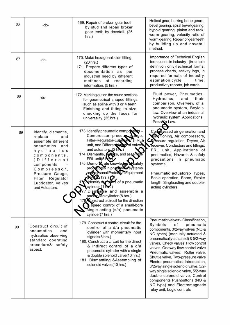
SYLLABUSFOURTH SEMESTER Duration: Six Months
Professional KnowledgeWeekNo.
Ref. LearningOutcome
Professional Skills with Indicative hrs.
Make drill j ig &produce componentson drill machine byusing jigs and checkfor correctness.
79 159. Make a simple drilling jig. (20hrs.)
160. Use simple jigs and fixtures fordrilling. (5 hrs.)
Drilling jig-constructional features,types and uses. Fixtures-Constructional features, types anduses.
80 Plan, dismantle, repairand assemble differentdamaged mechanicalcomponents used forpower transmission &check functionality.[Different DamageM e c h a n i c a lComponents – Pulley,Gear, Keys, Jibs andShafts.]
161. Marking out for angular outlines,filing and fitting the inserts intogaps. (10 hrs.)
162. Exercises on finished materialsuch as aluminium/ brass/ copper/ stainless steel, marking out,cutting to size, drilling, tappingetc. without damage to surface offinished articles. (15 hrs.)
Aluminium and its alloys. Uses,advantages and disadvantages,weight and strength as comparedwith steel. Non-ferrous metals suchas brass, phosphor bronze,gunmetal, copper, aluminium etc.Their composition and purposes,where and why used, advantagesfor specific purposes, surfacewearing properties of bronze andbrass.
81-do- 163. Making an adjustable spanner: -
Marking out as per Blue print,drilling, cutting, straight and curvefiling, threading, cutting slot andcutting internal threads with taps.(25 hrs.)
Installation, maintenance andoverhaul of machinery andengineering equipment. Powertransmission elements. Theobject of belts, their sizes andspecifications, materials of whichthe belts are made, selection ofthe type of belts with theconsideration of weather, load andtension methods of joining leatherbelts
82-84 -do- 164. Dismantling and mounting ofpulleys. (10 hrs.) 165. Making &replacing damaged keys. (15 hrs.)166. Dismounting, repairingdamaged gears and mounting andcheck for workability. (15 hrs.)167. Repair & replacement of beltsand check for workability. (10 hrs.)
Vee belts and their advantagesand disadvantages, Use ofcommercial belts, dressing andresin creep and slipping,calculation. Powertransmissions- couplingtypesflange coupling,-Hookscouplinguniversal coupling andtheir different uses. Pulleys-types-solid, split and „V? beltpulleys, standard calculation fordetermining size crowning offaces-loose and fast pulleys-jockey pulley. Types of drives-open and cross belt drives. Thegeometrical explanation of thebelt drivers at an angle.
168. Making of template/gauge tocheck involute profile. (25 hrs.)
85-do-
Power transmission –by gears,most common form spur gear, setnames of some essential partsof the set-The pitch circles,Diametral pitch, velocity ratio ofa gear set.
Copyrigh
t @ NIM
I
Not to be Republish
ed
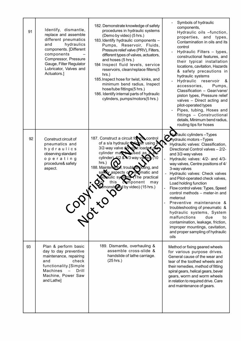
86 -do-169. Repair of broken gear tooth
by stud and repair brokergear teeth by dovetail. (25hrs.)
Helical gear, herring bone gears,bevel gearing, spiral bevel gearing,hypoid gearing, pinion and rack,worm gearing, velocity ratio ofworm gearing. Repair of gear teethby building up and dovetailmethod.
87 -do-170. Make hexagonal slide fitting.
(20 hrs.)171. Prepare different types of
documentation as perindustrial need by differentmethods of recordinginformation. (5 hrs.)
Importance of Technical Englishterms used in industry –(in simpledefinition only)Technical forms,process charts, activity logs, inrequired formats of industry,estimation,cycle time,productivity reports, job cards.
88 -do-172. Marking out on the round sections
for geometrical shaped fittingssuch as spline with 3 or 4 teeth.Finishing and fitting to size,checking up the faces foruniversality. (25 hrs.)
Fluid power, Pneumatics,Hydraulics, and theircomparison, Overview of apneumatic system, Boyle’slaw. Overview of an industrialhydraulic system, Applications,Pascal’s Law.
89 Identify, dismantle,replace andassemble differentpneumatics andh y d r a u l i c sc o m p o n e n t s .[ D i f f e r e n tcomponents –C o m p r e s s o r ,Pressure Gauge,Filter RegulatorLubricator, Valvesand Actuators.
173. Identify pneumatic components –Compressor, pressure gauge,Filter-Regulator-Lubricator (FRL)unit, and Different types of valvesand actuators. (2 hrs.)
174. Dismantle, replace, and assembleFRL unit(5 hrs.)
175. Demonstrate knowledge of safetyprocedures in pneumatic systemsand personal Protective Equipment(PPE)(2 hrs.)
176. Identify the parts of a pneumaticcylinder (1 hrs.)
177.Dismantle and assemble apneumatic cylinder (8 hrs.)
178. Construct a circuit for the direction& speed control of a small-boresingle-acting (s/a) pneumaticcylinder(7 hrs.)
Compressed air generation andconditioning, Air compressors,Pressure regulation, Dryers, Airreceiver, Conductors and fittings,FRL unit, Applications ofpneumatics, Hazards & safetyprecautions in pneumaticsystems.
Pneumatic actuators:- Types,Basic operation, Force, Strokelength, Singleacting and double-acting cylinders.
90 Construct circuit ofpneumatics andhydraulics observingstandard operatingprocedure& safetyaspect.
179. Construct a control circuit for thecontrol of a d/a pneumaticcylinder with momentary inputsignals(5 hrs.)
180. Construct a circuit for the direct& indirect control of a d/apneumatic cylinder with a single& double solenoid valve(10 hrs.)
181. Dismantling &Assembling ofsolenoid valves(10 hrs.)
Pneumatic valves:- Classification,Symbols of pneumaticcomponents, 3/2way valves (NO &NC types) (manually actuated &pneumatically-actuated) & 5/2-wayvalves, Check valves, Flow controlvalves, Oneway flow control valvePneumatic valves: Roller valve,Shuttle valve, Two-pressure valveElectro-pneumatics: Introduction,3/2way single solenoid valve, 5/2-way single solenoid valve, 5/2-waydouble solenoid valve, Controlcomponents Pushbuttons (NO &NC type) and Electromagneticrelay unit, Logic controls
Copyrigh
t @ NIM
I
Not to be Republish
ed
91 Identify, dismantle,replace and assembledifferent pneumaticsand hydraulicscomponents. [Differentcomponents –Compressor, PressureGauge, Filter RegulatorLubricator, Valves andActuators.]
182. Demonstrate knowledge of safetyprocedures in hydraulic systems(Demo by video) (5 hrs.)
183. Identify hydraulic components –Pumps, Reservoir, Fluids,Pressure relief valve (PRV), Filters,different types of valves, actuators,and hoses (5 hrs.)
184 Inspect fluid levels, servicereservoirs, clean/replace filters(5hrs.)
185.Inspect hose for twist, kinks, andminimum bend radius, Inspecthose/tube fittings(5 hrs.)
186. Identify internal parts of hydrauliccylinders, pumps/motors(5 hrs.)
- Symbols of hydrauliccomponents,Hydraulic oils –function,properties, and types,Contamination in oils and itscontrol
- Hydraulic Filters – types,constructional features, andtheir typical installationlocations, cavitation, Hazards& safety precautions inhydraulic systems
- Hydraulic reservoir &accessories, Pumps,Classification – Gear/vane/piston types, Pressure reliefvalves – Direct acting andpilot-operated types
- Pipes, tubing, Hoses andfittings – Constructionaldetails, Minimum bend radius,routing tips for hoses
92 Construct circuit ofpneumatics andh y d r a u l i c sobserving standardo p e r a t i n gprocedure& safetyaspect.
187. Construct a circuit for the controlof a s/a hydraulic cylinder using a3/2-way valve (Weight loaded d/acylinder may be used as a s/acylinder), 4/2 & 4/3 way valves. (10hrs.)
188. Maintenance, troubleshooting, andsafety aspects of pneumatic andhydraulic systems (The practicalfor this component maydemonstrated by video) (15 hrs.)
- Hydraulic cylinders –Types- Hydraulic motors –Types- Hydraulic valves: Classification,
Directional Control valves – 2/2-and 3/2-way valves
- Hydraulic valves: 4/2- and 4/3-way valves, Centre positions of 4/3-way valves
- Hydraulic valves: Check valvesand Pilot-operated check valves,Load holding function
- Flow control valves: Types, Speedcontrol methods – meter-in andmeterout
- Preventive maintenance &troubleshooting of pneumatic &hydraulic systems, Systemmalfunctions due tocontamination, leakage, friction,improper mountings, cavitation,and proper sampling of hydraulicoils
93 Method or fixing geared wheelsfor various purpose drives.General cause of the wear andtear of the toothed wheels andtheir remedies, method of fittingspiral gears, helical gears, bevelgears, worm and worm wheelsin relation to required drive. Careand maintenance of gears.
Plan & perform basicday to day preventivemaintenance, repairingand checkfunctionality.[SimpleMachines – DrillMachine, Power Sawand Lathe]
189. Dismantle, overhauling &assemble cross-slide &handslide of lathe carriage.(25 hrs.)
Copyrigh
t @ NIM
I
Not to be Republish
ed
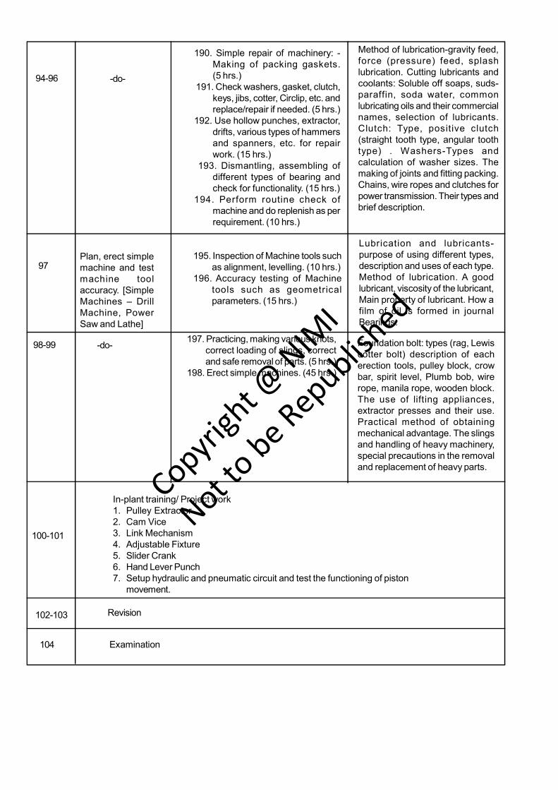
94-96 -do-
Method of lubrication-gravity feed,force (pressure) feed, splashlubrication. Cutting lubricants andcoolants: Soluble off soaps, suds-paraffin, soda water, commonlubricating oils and their commercialnames, selection of lubricants.Clutch: Type, positive clutch(straight tooth type, angular toothtype) . Washers-Types andcalculation of washer sizes. Themaking of joints and fitting packing.Chains, wire ropes and clutches forpower transmission. Their types andbrief description.
190. Simple repair of machinery: -Making of packing gaskets.(5 hrs.)
191. Check washers, gasket, clutch,keys, jibs, cotter, Circlip, etc. andreplace/repair if needed. (5 hrs.)
192. Use hollow punches, extractor,drifts, various types of hammersand spanners, etc. for repairwork. (15 hrs.)
193. Dismantling, assembling ofdifferent types of bearing andcheck for functionality. (15 hrs.)
194. Perform routine check ofmachine and do replenish as perrequirement. (10 hrs.)
97Plan, erect simplemachine and testmachine toolaccuracy. [SimpleMachines – DrillMachine, PowerSaw and Lathe]
195. Inspection of Machine tools suchas alignment, levelling. (10 hrs.)
196. Accuracy testing of Machinetools such as geometricalparameters. (15 hrs.)
Lubrication and lubricants-purpose of using different types,description and uses of each type.Method of lubrication. A goodlubricant, viscosity of the lubricant,Main property of lubricant. How afilm of oil is formed in journalBearings.
98-99 -do-197. Practicing, making various knots,
correct loading of slings, correctand safe removal of parts. (5 hrs.)
198. Erect simple machines. (45 hrs.)
Foundation bolt: types (rag, Lewiscotter bolt) description of eacherection tools, pulley block, crowbar, spirit level, Plumb bob, wirerope, manila rope, wooden block.The use of lifting appliances,extractor presses and their use.Practical method of obtainingmechanical advantage. The slingsand handling of heavy machinery,special precautions in the removaland replacement of heavy parts.
In-plant training/ Project work1. Pulley Extractor2. Cam Vice3. Link Mechanism4. Adjustable Fixture5. Slider Crank6. Hand Lever Punch7. Setup hydraulic and pneumatic circuit and test the functioning of piston
movement.
100-101
102-103
104
Revision
Examination
Copyrigh
t @ NIM
I
Not to be Republish
ed

Copyrigh
t @ NIM
I
Not to be Republish
ed

1
Production & Manufacturing Related Theory for Exercise No 4.1.159Fitter- Drill jig
Drilling jig constructional features, types and usesObjectives: At the end of this lesson you shall be to• what is jig• list the different types of drill jig and uses• state constructionl features of drill jig
Introduction to jigs
A jig is a device in which a work piece/component isheld and located for a specific operation in such a waythat it will guide one or more cutting tools to the samezone of machining.
Types of drill jigs
Drill jigs may be divided into two types
- Open
- Closed
Open jigs are used when the operation is to be doneonly on one side of the piece. Closed jigs (Box jig) areused when the operations are to be done on more thanone side of the piece. Jigs are identified according tothe way they are built. Most commonly used jigs are:
- Template jig
- Plate jig
- Table jig
- Sandwich jig
- Angle plate jig
- Modified angle plate jig
- Box jig
- Channel jig
- Leaf jig
- Indexing jig
- Solid jig
- Post jig
- Trunnion jig
Types of drill jigs
Template jigs
This type of jigs fits over on or into the work and is notusually clamped. They are simple and cheap. They mayor may not have guide bushes. When bushes are notused the whole jig plate may be (Fig 1)
The design of a particular type of jig will be based on:
- the position wherein the drilling or its allied operation/operations are to be performed
- the shape of the piece part.
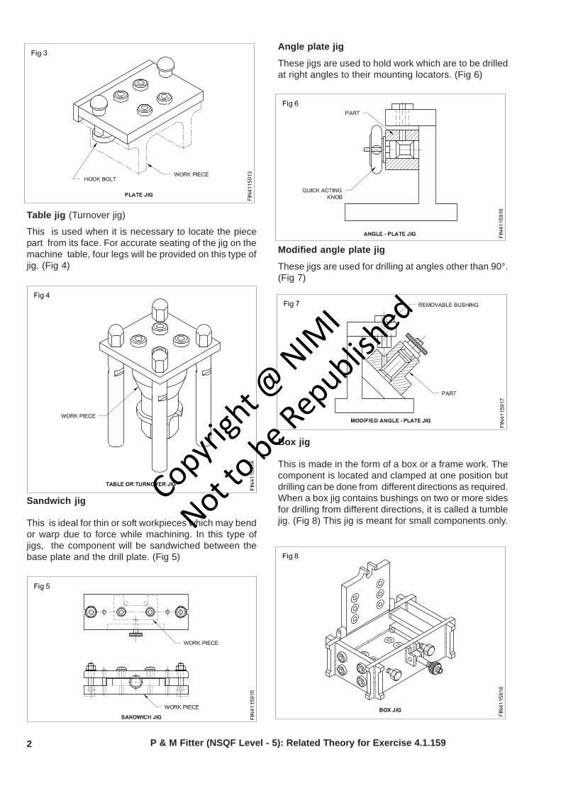
Plate jig
This jig consists of a drill plate which rests on thecomponent to be drilled. For correct positioning/locating,pins and clips are provided. For heavier piece parts,sometimes clamps are not used. Generally a baseplate will not be available for this type of jigs. (Figs 1, 2and 3)
Copyrigh
t @ NIM
I
Not to be Republish
ed
2
Table jig (Turnover jig)
This is used when it is necessary to locate the piecepart from its face. For accurate seating of the jig on themachine table, four legs will be provided on this type ofjig. (Fig 4)
Sandwich jig
This is ideal for thin or soft workpieces which may bendor warp due to force while machining. In this type ofjigs, the component will be sandwiched between thebase plate and the drill plate. (Fig 5)
P & M Fitter (NSQF Level - 5): Related Theory for Exercise 4.1.159
Angle plate jig
These jigs are used to hold work which are to be drilledat right angles to their mounting locators. (Fig 6)
Modified angle plate jig
These jigs are used for drilling at angles other than 90°.(Fig 7)
Box jig
This is made in the form of a box or a frame work. Thecomponent is located and clamped at one position butdrilling can be done from different directions as required.When a box jig contains bushings on two or more sidesfor drilling from different directions, it is called a tumblejig. (Fig 8) This jig is meant for small components only.
Copyrigh
t @ NIM
I
Not to be Republish
ed
3P & M Fitter (NSQF Level - 5): Related Theory for Exercise 4.1.159
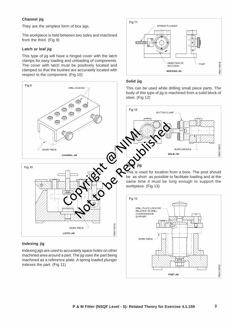
Channel jig
They are the simplest form of box jigs.
The workpiece is held between two sides and machinedfrom the third. (Fig 9)
Latch or leaf jig
This type of jig will have a hinged cover with the latchclamps for easy loading and unloading of components.The cover with latch must be positively located andclamped so that the bushes are accurately located withrespect to the component. (Fig 10)
Indexing jig
Indexing jigs are used to accurately space holes on othermachined area around a part. The jig uses the part beingmachined as a reference plate. A spring loaded plungerindexes the part. (Fig 11)
Solid jig
This can be used while drilling small piece parts. Thebody of this type of jig is machined from a solid block ofsteel. (Fig 12)
Post jig
This is used for location from a bore. The post shouldbe as short as possible to facilitate loading and at thesame time it must be long enough to support theworkpiece. (Fig 13)
Copyrigh
t @ NIM
I
Not to be Republish
ed
4
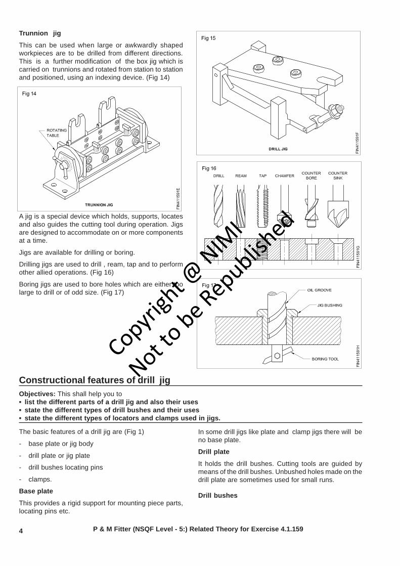
Trunnion jig
This can be used when large or awkwardly shapedworkpieces are to be drilled from different directions.This is a further modification of the box jig which iscarried on trunnions and rotated from station to stationand positioned, using an indexing device. (Fig 14)
A jig is a special device which holds, supports, locatesand also guides the cutting tool during operation. Jigsare designed to accommodate on or more componentsat a time.
Jigs are available for drilling or boring.
Drilling jigs are used to drill , ream, tap and to performother allied operations. (Fig 16)
Boring jigs are used to bore holes which are either toolarge to drill or of odd size. (Fig 17)
Constructional features of drill jigObjectives: This shall help you to• list the different parts of a drill jig and also their uses• state the different types of drill bushes and their uses• state the different types of locators and clamps used in jigs.
In some drill jigs like plate and clamp jigs there will beno base plate.
Drill plate
It holds the drill bushes. Cutting tools are guided bymeans of the drill bushes. Unbushed holes made on thedrill plate are sometimes used for small runs.
Drill bushes
P & M Fitter (NSQF Level - 5:) Related Theory for Exercise 4.1.159
The basic features of a drill jig are (Fig 1)
- base plate or jig body
- drill plate or jig plate
- drill bushes locating pins
- clamps.
Base plate
This provides a rigid support for mounting piece parts,locating pins etc.
Copyrigh
t @ NIM
I
Not to be Republish
ed

5P & M Fitter (NSQF Level - 5:) Related Theory for Exercise 4.1.159
They are used to locate and guide drills, reamers, tapsand any other revolving tools commonly used to makeor modify holes. (Fig 2)
These are hardened and ground to exact sizes to ensurethe needed repeatability in the jig. Standard size bushesare also available.
Types of drill bushes- Press fit bushes
- Renewable bushes
- Liner bushes
Press fit bushes are made in two forms.
- Head
- Headless
These bushes are used where frequent change of bushesis not anticipated. (Figs 3 and 4)
Renewable bushes are divided into two groups.
Slip renewable bushes (slip bushes)
These bushes are used when more than one operationis performed in the same location. (Eg:drilling andreaming) These bushes are used with press-fitted linerbushes and a lock clamp. (Fig 5)
Fixed renewable bushes
These bushes are used where only one operation is tobe performed with each bush, whereas several bushesmay be used during the life of the jig. These are alsoheld in a liner and retained by a screw. (Fig 6)
Liner bushes are used to provide a hardened hole whererenewable bushes are located. Liner bushes are press-fitted to the jig plate.(Fig 7)
Copyrigh
t @ NIM
I
Not to be Republish
ed
6 P & M Fitter (NSQF Level - 5:) Related Theory for Exercise 4.1.159
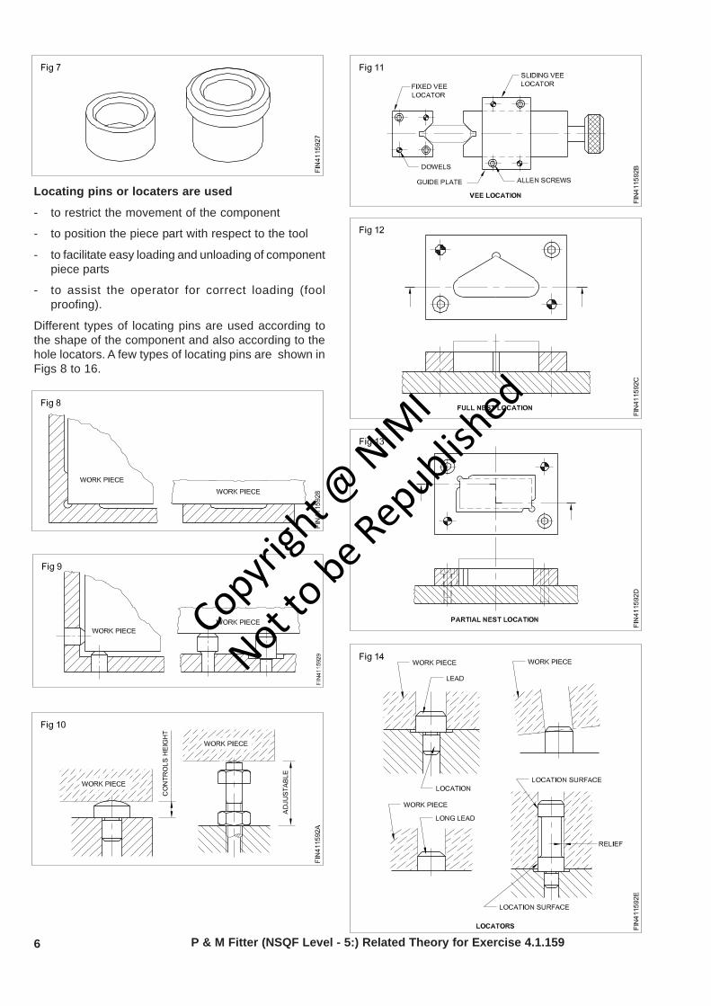
Locating pins or locaters are used
- to restrict the movement of the component
- to position the piece part with respect to the tool
- to facilitate easy loading and unloading of componentpiece parts
- to assist the operator for correct loading (foolproofing).
Different types of locating pins are used according tothe shape of the component and also according to thehole locators. A few types of locating pins are shown inFigs 8 to 16.
Copyrigh
t @ NIM
I
Not to be Republish
ed
7P & M Fitter (NSQF Level - 5:) Related Theory for Exercise 4.1.159
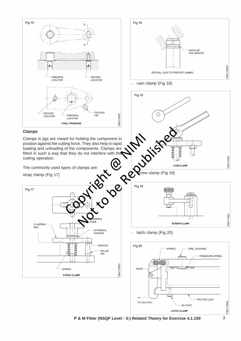
Clamps
Clamps in jigs are meant for holding the component inposition against the cutting force. They also help in rapidloading and unloading of the components. Clamps arefitted in such a way that they do not interfere with thecutting operation.
The commonly used types of clamps are:
strap clamp (Fig 17)
- cam clamp (Fig 18)
- screw clamp (Fig 19)
- latch clamp (Fig 20)
Copyrigh
t @ NIM
I
Not to be Republish
ed
8 P & M Fitter (NSQF Level - 5) Related Theory for Exercise 4.1.159
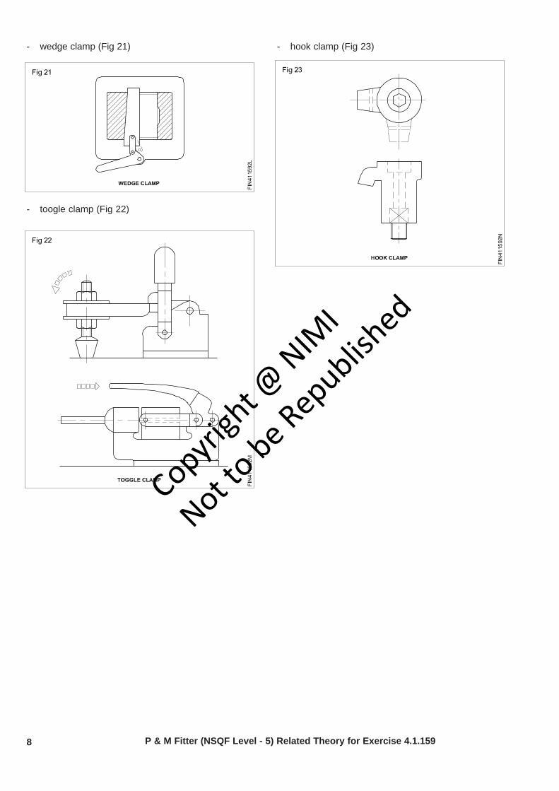
- wedge clamp (Fig 21)
- toogle clamp (Fig 22)
- hook clamp (Fig 23)
Copyrigh
t @ NIM
I
Not to be Republish
ed
9
Production & Manufacturing Related theory for Exercise No 4.1.160Fitter - Drill jig
Fixtures - constructional features,types and usesObjectives: At the end of this lesson you shall be to• what is fixture• list the different type of fixture and uses• state the constructional features of fixtures• state the functions of setting blocks and blancinng weight in fixture.
Introduction to fixture
A fixture is a production tool used to locate accuratelyand to hold securely one or more work- pieces so thatthe required machining operations can be performed.A fixture should be securely fastened to the table of themachine upon which the work is done. The main purposeof a fixture is to locate the work quickly andaccurately,support it properly ,and hold it securely.
Classification of fixtures
Fixtures are classified by the type of machine on whichthey are used. If a fixture is made for a milling machineit is called a milling fixture. Some of the most commonlyused fixtures are turning fixture, milling fixture, weldingfixture, boring fixture, assembly fixture, inspectionfixtures etc.
The elements of jigs and fixtures are
- location
- clamping
- tool guiding or setting
- body base or frame
Types of fixtures
Types of fixtures are determined mainly by how the toolis used. Because of the increased tool forces, fixturesare built stronger and heavier than jigs. The mostcommon type of fixtures are
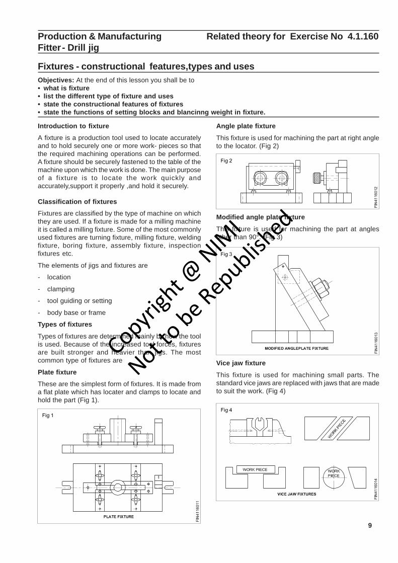
Plate fixture
These are the simplest form of fixtures. It is made froma flat plate which has locater and clamps to locate andhold the part (Fig 1).
Angle plate fixture
This fixture is used for machining the part at right angleto the locator. (Fig 2)
Modified angle plate fixture
This fixture is used for machining the part at anglesother than 90°. (Fig 3)
Vice jaw fixture
This fixture is used for machining small parts. Thestandard vice jaws are replaced with jaws that are madeto suit the work. (Fig 4)
Copyrigh
t @ NIM
I
Not to be Republish
ed
10
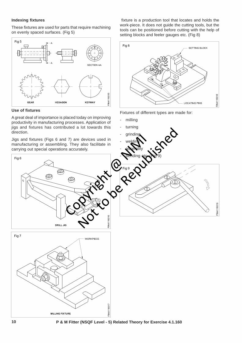
Indexing fixtures
These fixtures are used for parts that require machiningon evenly spaced surfaces. (Fig 5)
Use of fixtures
A great deal of importance is placed today on improvingproductivity in manufacturing processes. Application ofjigs and fixtures has contributed a lot towards thisdirection.
Jigs and fixtures (Figs 6 and 7) are devices used inmanufacturing or assembling. They also facilitate incarrying out special operations accurately.
fixture is a production tool that locates and holds thework-piece. It does not guide the cutting tools, but thetools can be positioned before cutting with the help ofsetting blocks and feeler gauges etc. (Fig 8)
Fixtures of different types are made for:
- milling
- turning
- grinding
- welding
- assembly
- bending etc. (Fig 9)
P & M Fitter (NSQF Level - 5) Related Theory for Exercise 4.1.160
Copyrigh
t @ NIM
I
Not to be Republish
ed
11P & M Fitter (NSQF Level - 5) Related Theory for Exercise 4.1.160
Constructional features of a fixtureObjective: This shall help you to• define various constructional features of a fixture.
common types of fixtures used for the machiningoperations are:
- milling fixture (Fig 1)
- turning fixture (Fig 2)
- grinding fixture etc.
These fixtures consist of a base plate, standard clampsand locators, setting blocks and balancing weights.
Base plate
The base plate for a milling fixture is provided withtenons at its bottom for proper location of the fixturewith the machine table through Tee slots. (Fig 3) Two orfour hold-down slots are provided in the base plate forrigid clamping of the fixture with the machine table.
Standard clamps and locators
These are provided for clamping and locating the
workpieces with the fixture as in the case of drill jigs.
The clamps used in the fixtures are very rigid and sturdy.
The setting blocks
These are used to position the fixture and work relativeto the cutter before machining.
A feeler is introduced between the cutter and the settingfaces of the block for correct positioning of the cutterwith the fixture. (Fig 4)
Balancing weight
This is used dynamically balancing the irregularworkpiece fixed to the turning or cylindrical grindingfixture.
Copyrigh
t @ NIM
I
Not to be Republish
ed

12
Difference between jigs and fixtures
P & M Fitter (NSQF Level - 5: ) Related Theory for Exercise 4.1.160
In the case of a turning fixture, normally the base plateof the fixture is clamped to the face plate. (Fig 5)
Vice fixture
Standard machine vices, attached with special jaws,provide an easy method of holding parts for machining.(Fig 6)
Other types of tooling used for positioning parts relativeto each other for fabricating purposes are also commonlyreferred to as fixtures. Bending fixtures, assemblyfixtures and welding fixtures are examples of this type.
The construction of a fixture depends upon themachining and fabricating methods employed.
Jigs Fixtures
jig holds and positions the work piece, guidesthe cutting tool
Jig is not fixed to the machine table
Jigs are used in drilling machine for drilling, tapping,
counter boring, and countersinking etc.
Fixture only hold and position the work piece,does not guide the cutting tool
Fixture is usually fixed to the machine table
Fixtures are used in grinding, milling, turning,
bending and assembling.
Copyrigh
t @ NIM
I
Not to be Republish
ed
13
Production & Manufacturing Related Theory for Exercise 4.2.161- 162Fitter - Repairing technique
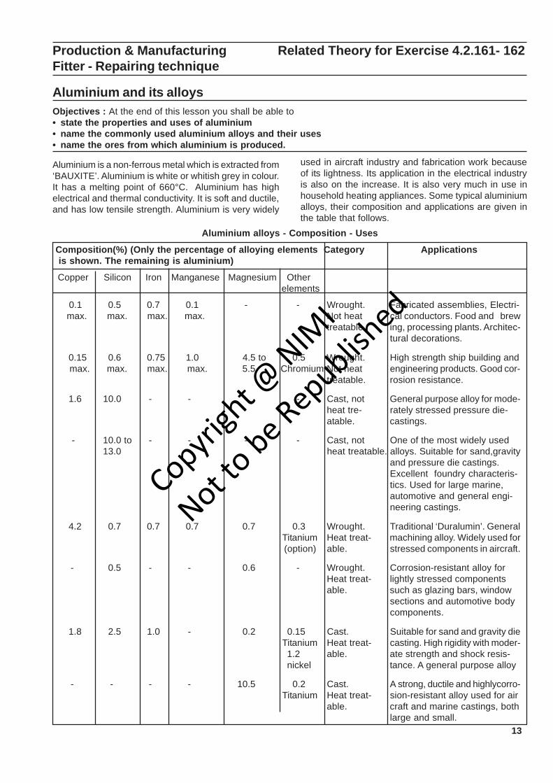
Aluminium and its alloysObjectives : At the end of this lesson you shall be able to• state the properties and uses of aluminium• name the commonly used aluminium alloys and their uses• name the ores from which aluminium is produced.
Aluminium is a non-ferrous metal which is extracted from‘BAUXITE’. Aluminium is white or whitish grey in colour.It has a melting point of 660°C. Aluminium has highelectrical and thermal conductivity. It is soft and ductile,and has low tensile strength. Aluminium is very widely
used in aircraft industry and fabrication work becauseof its lightness. Its application in the electrical industryis also on the increase. It is also very much in use inhousehold heating appliances. Some typical aluminiumalloys, their composition and applications are given inthe table that follows.
Aluminium alloys - Composition - Uses
Composition(%) (Only the percentage of alloying elements Category Applications is shown. The remaining is aluminium)
Copper Silicon Iron Manganese Magnesium Other elements
0.1 0.5 0.7 0.1 - - Wrought. Fabricated assemblies, Electri- max. max. max. max. Not heat cal conductors. Food and brew
treatable. ing, processing plants. Architec-tural decorations.
0.15 0.6 0.75 1.0 4.5 to 0.5 Wrought. High strength ship building and max. max. max. max. 5.5 Chromium Not heat engineering products. Good cor-
treatable. rosion resistance.
1.6 10.0 - - - - Cast, not General purpose alloy for mode-heat tre- rately stressed pressure die-atable. castings.
- 10.0 to - - - - Cast, not One of the most widely used13.0 heat treatable. alloys. Suitable for sand,gravity
and pressure die castings.Excellent foundry characteris-tics. Used for large marine,automotive and general engi-neering castings.
4.2 0.7 0.7 0.7 0.7 0.3 Wrought. Traditional ‘Duralumin’. General Titanium Heat treat- machining alloy. Widely used for (option) able. stressed components in aircraft.
- 0.5 - - 0.6 - Wrought. Corrosion-resistant alloy forHeat treat- lightly stressed componentsable. such as glazing bars, window
sections and automotive bodycomponents.
1.8 2.5 1.0 - 0.2 0.15 Cast. Suitable for sand and gravity die Titanium Heat treat- casting. High rigidity with moder-
1.2 able. ate strength and shock resis- nickel tance. A general purpose alloy
- - - - 10.5 0.2 Cast. A strong, ductile and highlycorro- Titanium Heat treat- sion-resistant alloy used for air
able. craft and marine castings, bothlarge and small.
Copyrigh
t @ NIM
I
Not to be Republish
ed
14
Advantages of using aluminium over steel
Advantages
• lighter
• strength comparable to steel
• corrosion resistance
• good machinability
• can be anodized
• better thermal and electrical conductivity
Disadvantages
• less strength (compared to the higher strength steelalloys)
• not good for threaded fasteners
• more difficult to paint
• weldments require post welding heat treat to recovermechanical properties
• more difficult to weld
• fatigues
• high cost
• lower modulus of elasticity,therefore,increaseddeformation
• low elongation values
Aluminium and aluminium alloys
Aluminium is one of the most widely used metals in theworld. It possesses an exciting range of properties.Moreover,aluminium combines with alloying elementslike copper. manganese,silicon,magnesium and zinc,andforms a very useful series of alloys.
Important properties
• Aluminium is a light weight metal. Its density is about2.7 gm/cm3. It is about one third as light as steel.
• While pure aluminium has a low strength of 7 kgf/mm2, the alloys are moderately strong Some alloyshave strength as high as 45 kgt/mm2 in the heat -treated condition.
• The above two properties together provide it withhigh strength to weight ratio,which makes it suitablefor aerospace application.
• Some of the alloys have excellent toughness at lowtemperatures,making them suitable for cryogenic(below 0° C) application.
• Some alloys have excellent corrosion resistance.
• Aluminium and its alloys have high thermalconductivity.
• Aluminium and its alloys also have high electricalconductivity.
Applications
• Household furniture and utensils.
• Containers,tanks and vessels.
• Automobile structures,bus bodies,road and railwaytankers and wagons.
• Buildings and other architectural structures.
• Portable bridges.
• Aircraft,missiles and other aerospace components.
• Radiators and other heat exchangers.
• Electrical conductor cables and bus bars.
Aluminium alloy system
Aluminium alloys are classified on the basis of theprincipal alloying element present in a particular alloy.
Production & Manufacturing : Fitter (NSQF Level - 5:) Related Theory for Exercise 4.2.161-162
Lead and its alloysObjectives : At the end of this lesson you shall be able to• state the properties of lead• state the various uses of lead• state the uses of babbit metal.
Lead is a very commonly used non-ferrous metal andhas a variety of industrial applications.
Lead is produced from its ore ‘GALENA’. Lead is a heavymetal that is silvery in colour when molten. It is soft andmalleable and has good resistance to corrosion. It is agood insulator against nuclear radiation. Lead isresistant to many acids like sulphuric acid andhydrochloric acid.
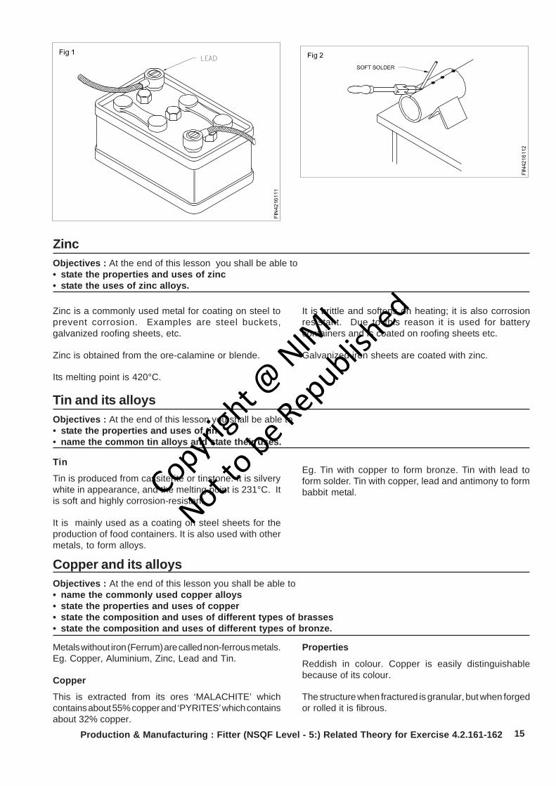
It is used in car batteries, in the preparation of soldersetc. It is also used in the preparation of paints.(Fig 1)
Lead Alloys
Babbit metal
Babbit metal is an alloy of lead, tin, copper andantimony. It is a soft, anti-friction alloy, often used asbearings.
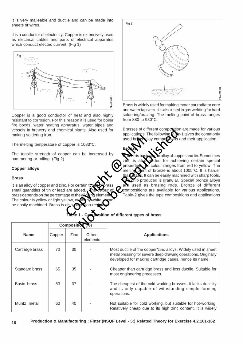
An alloy of lead and tin is used as ‘soft solder’.(Fig 2)
Copyrigh
t @ NIM
I
Not to be Republish
ed
15Production & Manufacturing : Fitter (NSQF Level - 5:) Related Theory for Exercise 4.2.161-162
ZincObjectives : At the end of this lesson you shall be able to• state the properties and uses of zinc• state the uses of zinc alloys.
Zinc is a commonly used metal for coating on steel toprevent corrosion. Examples are steel buckets,galvanized roofing sheets, etc.
Zinc is obtained from the ore-calamine or blende.
Its melting point is 420°C.
It is brittle and softens on heating; it is also corrosionresistant. Due to this reason it is used for batterycontainers and is coated on roofing sheets etc.
Galvanized iron sheets are coated with zinc.
Tin and its alloysObjectives : At the end of this lesson you shall be able to• state the properties and uses of tin• name the common tin alloys and state their uses.
Tin
Tin is produced from cassiterite or tinstone. It is silverywhite in appearance, and the melting point is 231°C. Itis soft and highly corrosion-resistant.
It is mainly used as a coating on steel sheets for theproduction of food containers. It is also used with othermetals, to form alloys.
Eg. Tin with copper to form bronze. Tin with lead toform solder. Tin with copper, lead and antimony to formbabbit metal.
Copper and its alloysObjectives : At the end of this lesson you shall be able to• name the commonly used copper alloys• state the properties and uses of copper• state the composition and uses of different types of brasses• state the composition and uses of different types of bronze.
Metals without iron (Ferrum) are called non-ferrous metals.Eg. Copper, Aluminium, Zinc, Lead and Tin.
Copper
This is extracted from its ores ‘MALACHITE’ whichcontains about 55% copper and ‘PYRITES’ which containsabout 32% copper.
Properties
Reddish in colour. Copper is easily distinguishablebecause of its colour.
The structure when fractured is granular, but when forgedor rolled it is fibrous.
Copyrigh
t @ NIM
I
Not to be Republish
ed
16
It is very malleable and ductile and can be made intosheets or wires.
It is a conductor of electricity. Copper is extensively usedas electrical cables and parts of electrical apparatuswhich conduct electric current. (Fig 1)
Copper is a good conductor of heat and also highlyresistant to corrosion. For this reason it is used for boilerfire boxes, water heating apparatus, water pipes andvessels in brewery and chemical plants. Also used formaking soldering iron.
The melting temperature of copper is 1083°C.
The tensile strength of copper can be increased byhammering or rolling. (Fig 2)
Copper alloys
Brass
It is an alloy of copper and zinc. For certain types of brasssmall quantities of tin or lead are added. The colour ofbrass depends on the percentage of the alloying elements.The colour is yellow or light yellow, or nearly white. It canbe easily machined. Brass is also corrosion-resistant.
Brass is widely used for making motor car radiator coreand water taps etc. It is also used in gas welding for hardsoldering/brazing. The melting point of brass rangesfrom 880 to 930°C.
Brasses of different composition are made for variousapplications. The following table-1 gives the commonlyused brass alloy compositions and their application.
Bronze
Bronze is basically an alloy of copper and tin. Sometimeszinc is also added for achieving certain specialproperties. Its colour ranges from red to yellow. Themelting point of bronze is about 1005°C. It is harderthan brass. It can be easily machined with sharp tools.The chip produced is granular. Special bronze alloysare used as brazing rods. Bronze of differentcompositions are available for various applications.Table-2 gives the type compositions and applications
Production & Manufacturing : Fitter (NSQF Level - 5:) Related Theory for Exercise 4.2.161-162
Composition (%)
Name Copper Zinc Other Applications elements
Cartridge brass 70 30 - Most ductile of the copper/zinc alloys. Widely used in sheetmetal pressing for severe deep drawing operations. Originallydeveloped for making cartridge cases, hence its name.
Standard brass 65 35 - Cheaper than cartridge brass and less ductile. Suitable formost engineering processes.
Basic brass 63 37 - The cheapest of the cold working brasses. It lacks ductilityand is only capable of withstanding simple formingoperations.
Muntz metal 60 40 - Not suitable for cold working, but suitable for hot-working.Relatively cheap due to its high zinc content. It is widely
Table 1 - Composition of different types of brassCopyrigh
t @ NIM
I
Not to be Republish
ed
17Production & Manufacturing : Fitter (NSQF Level - 5:) Related Theory for Exercise 4.2.161-162
Muntz metal 60 40 - Not suitable for cold working, but suitable for hot-working.Relatively cheap due to its high zinc content. It is widelyused for extrusion and hot-stamping processes.
Free-cutting brass 58 39 3% lead Not suitable for cold working but excellent for hot workingand high speed machining of low strength components.
Admirality brass 70 29 1% tin This is virtually cartridge brass plus a little tin to preventcorrosion in the presence of salt water.
Naval brass 62 37 1% tin This is virtually Muntz metal plus a little tin to preventcorrosion in the presence of salt water.
Gilding metal 95 5 - Used for jewellery.
Table 2 - Composition of different types of bronze
Composition (%)
Name Copper Zinc Phosphorus Tin Applications
Low tin 96 - 0.1 3.9 This alloy can be severely cold-worked to hardenbronze to to it so that it can be used for springs where good
0.25 3.75 elastic properties must be combined with corro-sion resistance,fatigue-resistance and electricalconductivity. Eg.Contact blades
Drawn 94 - 0.1 5.9 This alloy is used for turned components requiringphosphor/ to to strength and corrosion resistance, such as valvebronze 0.5 5.5 spindles.
Cast 89.75 0.03 10 Usually cast into rods and tubes for making bear-phosphor/ to to ing bushes and worm wheels. It has excellentbronze 89.97 0.25 anti-friction properties.
Admirality 88 2 - 10 This alloy is suitable for sand casting where fine-gun-metal grained, pressure-tight components such as pump
and valve bodies are required.
Leaded 85 5 - 5 Also known as ‘red brass’ this alloy is used for thegun-metal (5%lead) same purposes as standard, admirality gun-metal.(free cutting) It is rather less strong but has improved toughness
and machining properties.
Leaded 74 (24%lead) - 2 This alloy is used for lightly loaded bearings where(plastic) alignment is difficult. Due to its softness, bearingsbronze made from this alloy ‘bed in’ easily.
Copyrigh
t @ NIM
I
Not to be Republish
ed
18
Production & Manufacturing Related Theory for Exercise 4.2.163Fitter - Repairing technique
Installation,maintenance and overhaul of machineryObjectives : At the end of this lesson you shall be able to• explain installation procedure• state maintenance of machine• desribe overhauling procedure
Installation
The sequence of installation methods are as follows.
• foundations
• fitting and moving
• levelling
• testing
Foundations
Machinery foundation is a built up structure designed tosupport the machine and to take up the static anddynamic load of the machine,besides keeping themachine in alignment
The machine foundation must fullfil the followingrequirments.
• It must support the machines at a given height andmust be able to take up the static and dynamic loads.
• It should preserve the alignment of the machine
• It should absorb the vibration of the moving parts
Lifting and moving
For lifting and moving the machines,the equipments likehoists,derricks and cranes are employed and also ropesare used to tie the machine
Levelling
It is necessary to provide a good solid foundation uponwhich the machine is set and accurately levelled.Performance of any machine tool depends upon its leveland foundation.
Levelling of a machine is done using:
steel wedges
levelling blocks
jacking screws.
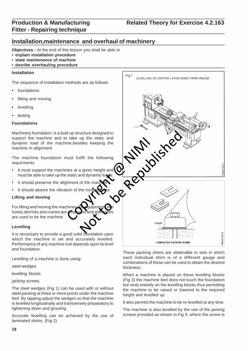
The steel wedges (Fig 1) can be used with or withoutsteel packing at three or more points under the machinebed. By tapping,adjust the wedges so that the machineis levelled longitudinally and transversely preparatory totightening down and grouting.
Accurate levelling can be achieved by the use oflaminated shims. (Fig 2)
These packing shims are obtainable in sets in whicheach individual shim is of a different gauge andcombinations of these can be used to obtain the desiredthickness.
When a machine is placed on these levelling blocks(Fig 3) the machine bed does not touch the foundationbut rests entirely on the levelling blocks thus permittingthe machine to be raised or lowered to the requiredheight and levelled up.
It also permits the machine to be re-levelled at any time.
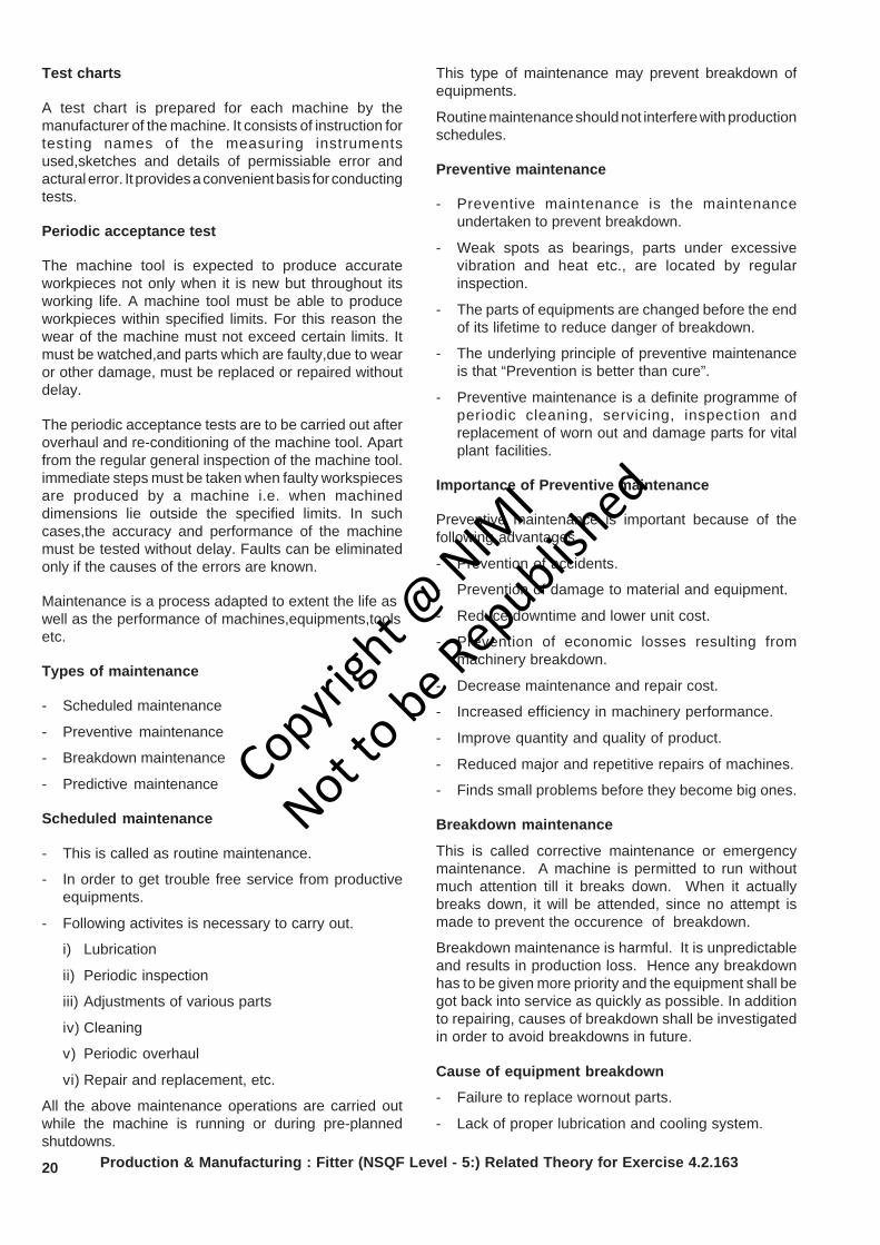
The machine is also levelled by the use of the jackingscrews provided as shown in Fig 4, where the screw is
Copyrigh
t @ NIM
I
Not to be Republish
ed
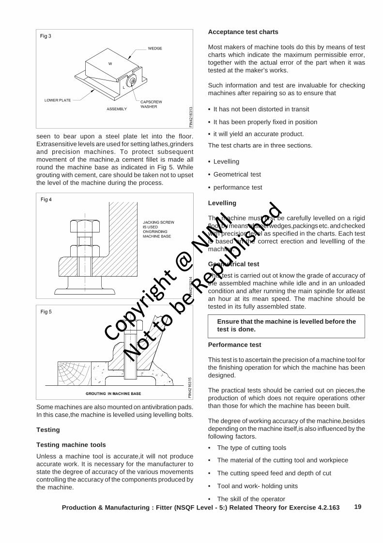
19Production & Manufacturing : Fitter (NSQF Level - 5:) Related Theory for Exercise 4.2.163
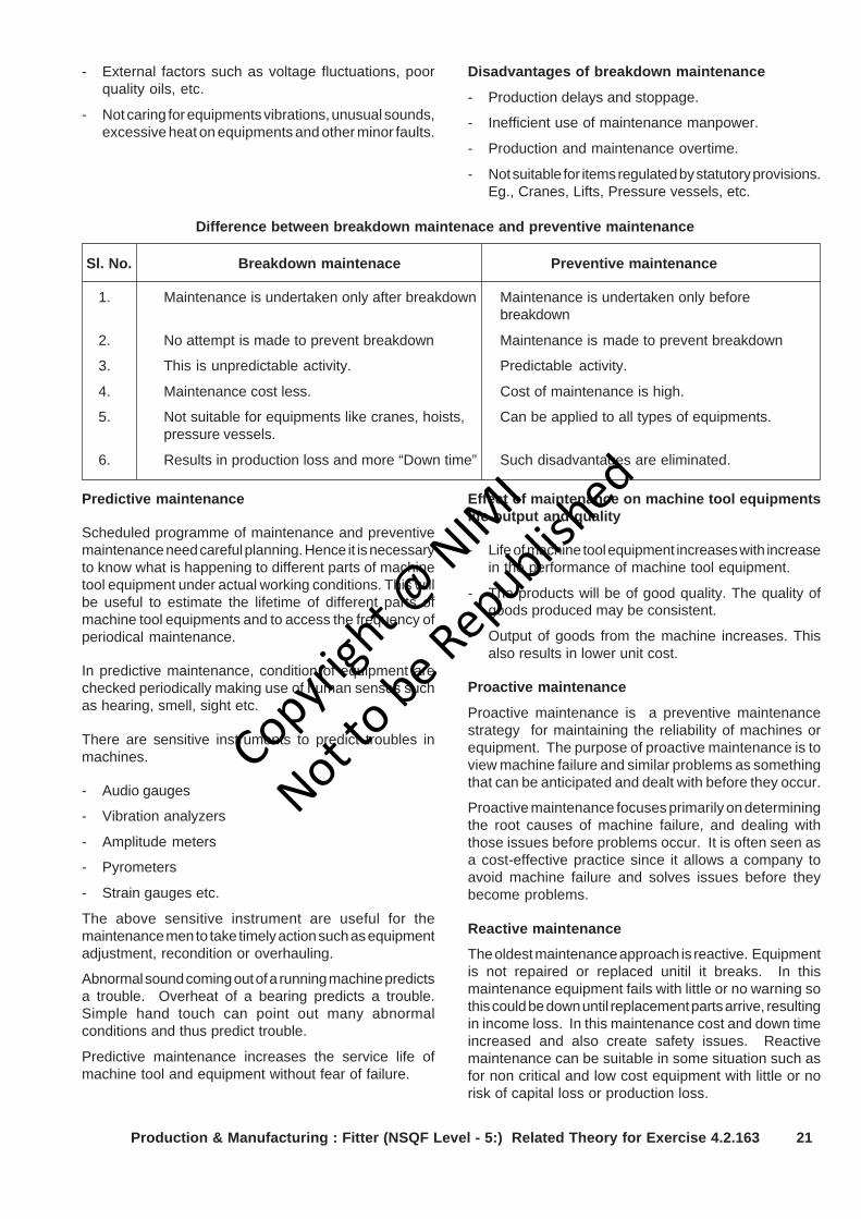
seen to bear upon a steel plate let into the floor.Extrasensitive levels are used for setting lathes,grindersand precision machines. To protect subsequentmovement of the machine,a cement fillet is made allround the machine base as indicated in Fig 5. Whilegrouting with cement, care should be taken not to upsetthe level of the machine during the process.
Some machines are also mounted on antivibration pads.In this case,the machine is levelled using levelling bolts.
Testing
Testing machine tools
Unless a machine tool is accurate,it will not produceaccurate work. It is necessary for the manufacturer tostate the degree of accuracy of the various movementscontrolling the accuracy of the components produced bythe machine.
Acceptance test charts
Most makers of machine tools do this by means of testcharts which indicate the maximum permissible error,together with the actual error of the part when it wastested at the maker’s works.
Such information and test are invaluable for checkingmachines after repairing so as to ensure that
• It has not been distorted in transit
• It has been properly fixed in position
• it will yield an accurate product.
The test charts are in three sections.
• Levelling
• Geometrical test
• performance test
Levelling
The machine must first be carefully levelled on a rigidfloor by means of steel wedges,packings etc. and checkedwith precision level as specified in the charts. Each testis based on the correct erection and levellling of themachine.
Geometrical test
This test is carried out ot know the grade of accuracy ofthe assembled machine while idle and in an unloadedcondition and after running the main spindle for atleastan hour at its mean speed. The machine should betested in its fully assembled state.
Ensure that the machine is levelled before thetest is done.
Performance test
This test is to ascertain the precision of a machine tool forthe finishing operation for which the machine has beendesigned.
The practical tests should be carried out on pieces,theproduction of which does not require operations otherthan those for which the machine has beeen built.
The degree of working accuracy of the machine,besidesdepending on the machine itself,is also influenced by thefollowing factors.
• The type of cutting tools
• The material of the cutting tool and workpiece
• The cutting speed feed and depth of cut
• Tool and work- holding units
• The skill of the operator
Copyrigh
t @ NIM
I
Not to be Republish
ed
20
Test charts
A test chart is prepared for each machine by themanufacturer of the machine. It consists of instruction fortesting names of the measuring instrumentsused,sketches and details of permissiable error andactural error. It provides a convenient basis for conductingtests.
Periodic acceptance test
The machine tool is expected to produce accurateworkpieces not only when it is new but throughout itsworking life. A machine tool must be able to produceworkpieces within specified limits. For this reason thewear of the machine must not exceed certain limits. Itmust be watched,and parts which are faulty,due to wearor other damage, must be replaced or repaired withoutdelay.
The periodic acceptance tests are to be carried out afteroverhaul and re-conditioning of the machine tool. Apartfrom the regular general inspection of the machine tool.immediate steps must be taken when faulty workspiecesare produced by a machine i.e. when machineddimensions lie outside the specified limits. In suchcases,the accuracy and performance of the machinemust be tested without delay. Faults can be eliminatedonly if the causes of the errors are known.
Maintenance is a process adapted to extent the life aswell as the performance of machines,equipments,toolsetc.
Types of maintenance
- Scheduled maintenance
- Preventive maintenance
- Breakdown maintenance
- Predictive maintenance
Scheduled maintenance
- This is called as routine maintenance.
- In order to get trouble free service from productiveequipments.
- Following activites is necessary to carry out.
i) Lubrication
ii) Periodic inspection
iii) Adjustments of various parts
iv) Cleaning
v) Periodic overhaul
vi) Repair and replacement, etc.
All the above maintenance operations are carried outwhile the machine is running or during pre-plannedshutdowns.
This type of maintenance may prevent breakdown ofequipments.
Routine maintenance should not interfere with productionschedules.
Preventive maintenance
- Preventive maintenance is the maintenanceundertaken to prevent breakdown.
- Weak spots as bearings, parts under excessivevibration and heat etc., are located by regularinspection.
- The parts of equipments are changed before the endof its lifetime to reduce danger of breakdown.
- The underlying principle of preventive maintenanceis that “Prevention is better than cure”.
- Preventive maintenance is a definite programme ofperiodic cleaning, servicing, inspection andreplacement of worn out and damage parts for vitalplant facilities.
Importance of Preventive maintenance
Preventive maintenance is important because of thefollowing advantages.
- Prevention of accidents.
- Prevention of damage to material and equipment.
- Reduce downtime and lower unit cost.
- Prevention of economic losses resulting frommachinery breakdown.
- Decrease maintenance and repair cost.
- Increased efficiency in machinery performance.
- Improve quantity and quality of product.
- Reduced major and repetitive repairs of machines.
- Finds small problems before they become big ones.
Breakdown maintenance
This is called corrective maintenance or emergencymaintenance. A machine is permitted to run withoutmuch attention till it breaks down. When it actuallybreaks down, it will be attended, since no attempt ismade to prevent the occurence of breakdown.
Breakdown maintenance is harmful. It is unpredictableand results in production loss. Hence any breakdownhas to be given more priority and the equipment shall begot back into service as quickly as possible. In additionto repairing, causes of breakdown shall be investigatedin order to avoid breakdowns in future.
Cause of equipment breakdown
- Failure to replace wornout parts.
- Lack of proper lubrication and cooling system.
Production & Manufacturing : Fitter (NSQF Level - 5:) Related Theory for Exercise 4.2.163
Copyrigh
t @ NIM
I
Not to be Republish
ed
21Production & Manufacturing : Fitter (NSQF Level - 5:) Related Theory for Exercise 4.2.163
- External factors such as voltage fluctuations, poorquality oils, etc.
- Not caring for equipments vibrations, unusual sounds,excessive heat on equipments and other minor faults.
Disadvantages of breakdown maintenance
- Production delays and stoppage.
- Inefficient use of maintenance manpower.
- Production and maintenance overtime.
- Not suitable for items regulated by statutory provisions.Eg., Cranes, Lifts, Pressure vessels, etc.
Difference between breakdown maintenace and preventive maintenance
Sl. No. Breakdown maintenace Preventive maintenance
1. Maintenance is undertaken only after breakdown Maintenance is undertaken only beforebreakdown
2. No attempt is made to prevent breakdown Maintenance is made to prevent breakdown
3. This is unpredictable activity. Predictable activity.
4. Maintenance cost less. Cost of maintenance is high.
5. Not suitable for equipments like cranes, hoists, Can be applied to all types of equipments.pressure vessels.
6. Results in production loss and more “Down time” Such disadvantages are eliminated.
Predictive maintenance
Scheduled programme of maintenance and preventivemaintenance need careful planning. Hence it is necessaryto know what is happening to different parts of machinetool equipment under actual working conditions. This willbe useful to estimate the lifetime of different parts ofmachine tool equipments and to access the frequency ofperiodical maintenance.
In predictive maintenance, condition of equipment arechecked periodically making use of human senses suchas hearing, smell, sight etc.
There are sensitive instruments to predict troubles inmachines.
- Audio gauges
- Vibration analyzers
- Amplitude meters
- Pyrometers
- Strain gauges etc.
The above sensitive instrument are useful for themaintenance men to take timely action such as equipmentadjustment, recondition or overhauling.
Abnormal sound coming out of a running machine predictsa trouble. Overheat of a bearing predicts a trouble.Simple hand touch can point out many abnormalconditions and thus predict trouble.
Predictive maintenance increases the service life ofmachine tool and equipment without fear of failure.
Effect of maintenance on machine tool equipmentslife output and quality
- Life of machine tool equipment increases with increasein the performance of machine tool equipment.
- The products will be of good quality. The quality ofgoods produced may be consistent.
- Output of goods from the machine increases. Thisalso results in lower unit cost.
Proactive maintenance
Proactive maintenance is a preventive maintenancestrategy for maintaining the reliability of machines orequipment. The purpose of proactive maintenance is toview machine failure and similar problems as somethingthat can be anticipated and dealt with before they occur.
Proactive maintenance focuses primarily on determiningthe root causes of machine failure, and dealing withthose issues before problems occur. It is often seen asa cost-effective practice since it allows a company toavoid machine failure and solves issues before theybecome problems.
Reactive maintenance
The oldest maintenance approach is reactive. Equipmentis not repaired or replaced unitil it breaks. In thismaintenance equipment fails with little or no warning sothis could be down until replacement parts arrive, resultingin income loss. In this maintenance cost and down timeincreased and also create safety issues. Reactivemaintenance can be suitable in some situation such asfor non critical and low cost equipment with little or norisk of capital loss or production loss.
Copyrigh
t @ NIM
I
Not to be Republish
ed
22 Production & Manufacturing : Fitter (NSQF Level - 5:) Related Theory for Exercise 4.2.163
Importance of breakdown maintenance andpreventive maintenance in productivity
The importance of an effective maintenance programcannot be overlooked because it plays such an importantrole in the effectiveness of lean manufacturing. As inpersonal health care insurance, maintenance may beconsidered the health care of our manufacturingmachines and equipment. It is required to effectivelydecrease waste and run an efficient, continuousmanufacturing operation, business, or service operation.The cost of routine maintenance is very small when it iscompared to the cost of a major breakdown at which timethere is no production.
Purpose of maintenance
The importance use of routine maintenance is to ensurethat all equipment required for production is operating at100% efficiency at all times. Through short dailyinspections, cleaning, lubricating and making smalladjustment, small problems can be detected andcorrected before they become a major problem that canshut down a production line. A good maintenanceprogram requires company wide participation and supportby everyone ranging from the top executive to the shopfloor personel.
Overhauling
Ensure that all the lubrication points are lubricatedregularly as recommended in the manual.
Use Servoway-32 oil for the pillar. Anti-frictional bearingson the main spindle head are to be lubricated by ServogemGrease - 2 once in 3 months.
If the spindle is supported by plain bearings,use Servo-System 32 oil.
Check the belt tension once in three months. If necessary,adjust the tension.
When replacing with a new belt, if required,check thetension of the belt after a week,and adjust, if necessary.
The machine should be overhauled once in 2 or 3 yearsdepending upon the usage.
Anti-friction bearing should not be cleaned usingcompressed air as compressed air normally containswater particles which will corrode the bearing. Also whileusing compressed air, dust, dirt and other absasiveparticles will be whirling in the surrounding areas andenter into the bearing causing damage to the race - waysand rolling elements.
Antifriction bearings should be handled indust free environment.
Types of belts and fastenersObjectives : At the end of this lesson you shall be able to• name the different types of belts• state the belt tension• state method of adjusting belt tension• name the different types of belt fasteners.
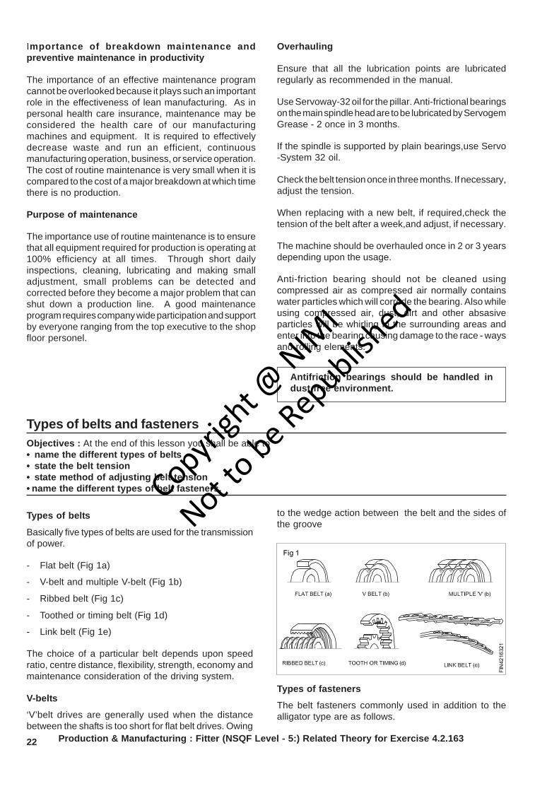
Types of belts
Basically five types of belts are used for the transmissionof power.
- Flat belt (Fig 1a)
- V-belt and multiple V-belt (Fig 1b)
- Ribbed belt (Fig 1c)
- Toothed or timing belt (Fig 1d)
- Link belt (Fig 1e)
The choice of a particular belt depends upon speedratio, centre distance, flexibility, strength, economy andmaintenance consideration of the driving system.
V-belts
‘V’belt drives are generally used when the distancebetween the shafts is too short for flat belt drives. Owing
to the wedge action between the belt and the sides ofthe groove
Types of fasteners
The belt fasteners commonly used in addition to thealligator type are as follows.
Copyrigh
t @ NIM
I
Not to be Republish
ed

23Production & Manufacturing : Fitter (NSQF Level - 5:) Related Theory for Exercise 4.2.163
Wire type belt fastener
Fig 2 shows the wire type fastener generally used onlight duty machines.
‘Lagrelle’ type belt fastener
Fig 3 shows a lagrelle type fastener used on heavy dutymachines.
Jackson-type belt fastener
The Jackson-type fastener illustrated in Fig 4 is usedon medium duty machines.
Crescent plate belt fastener
Fig 5 shows a mechanical type belt fastner which isused on medium duty machines.
Belt fasteners (Alligator type)
Alligator type fasteners are used in joining belting forindustrial purposes. The belt fastener is made of steelsheets conforming to IS:513-1973. The pins shall bemade from mild steel wire conforming to lS: 280-1972.Belt fasteners are shown in Fig 6 and the position of thepin in a joint is illustrated in Fig 7.
Specification
The fastener designation and pin size, thickness ofbelt and other dimensions are given in the table as perIS: 5593-1980.
Copyrigh
t @ NIM
I
Not to be Republish
ed
24 Production & Manufacturing : Fitter (NSQF Level - 5:) Related Theory for Exercise 4.2.163
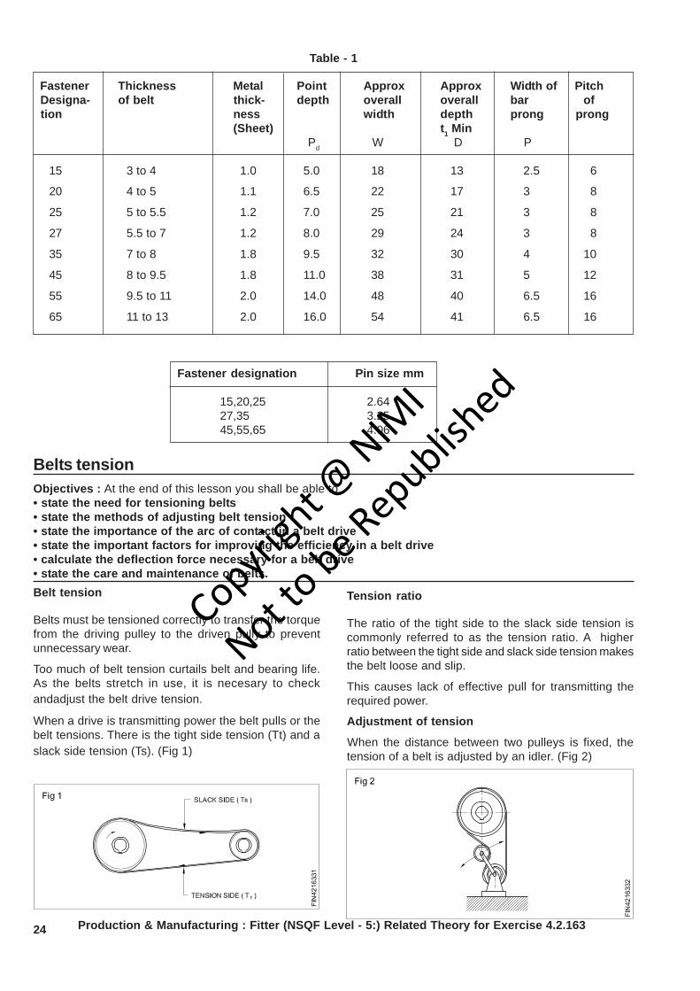
Table - 1
Fastener Thickness Metal Point Approx Approx Width of Pitch Designa- of belt thick- depth overall overall bar of tion ness width depth prong prong
(Sheet) t1 Min Pd W D P
15 3 to 4 1.0 5.0 18 13 2.5 6
20 4 to 5 1.1 6.5 22 17 3 8
25 5 to 5.5 1.2 7.0 25 21 3 8
27 5.5 to 7 1.2 8.0 29 24 3 8
35 7 to 8 1.8 9.5 32 30 4 10
45 8 to 9.5 1.8 11.0 38 31 5 12
55 9.5 to 11 2.0 14.0 48 40 6.5 16
65 11 to 13 2.0 16.0 54 41 6.5 16
Fastener designation Pin size mm
15,20,25 2.6427,35 3.2545,55,65 4.06
Belts tensionObjectives : At the end of this lesson you shall be able to• state the need for tensioning belts• state the methods of adjusting belt tension• state the importance of the arc of contact in a belt drive• state the important factors for improving the efficiency in a belt drive• calculate the deflection force necessary for a belt drive• state the care and maintenance of belts.Belt tension
Belts must be tensioned correctly to transfer the torquefrom the driving pulley to the driven pully to preventunnecessary wear.
Too much of belt tension curtails belt and bearing life.As the belts stretch in use, it is necesary to checkandadjust the belt drive tension.
When a drive is transmitting power the belt pulls or thebelt tensions. There is the tight side tension (Tt) and aslack side tension (Ts). (Fig 1)
Tension ratio
The ratio of the tight side to the slack side tension iscommonly referred to as the tension ratio. A higherratio between the tight side and slack side tension makesthe belt loose and slip.
This causes lack of effective pull for transmitting therequired power.
Adjustment of tension
When the distance between two pulleys is fixed, thetension of a belt is adjusted by an idler. (Fig 2)
Copyrigh
t @ NIM
I
Not to be Republish
ed
25Production & Manufacturing : Fitter (NSQF Level - 5:) Related Theory for Exercise 4.2.163
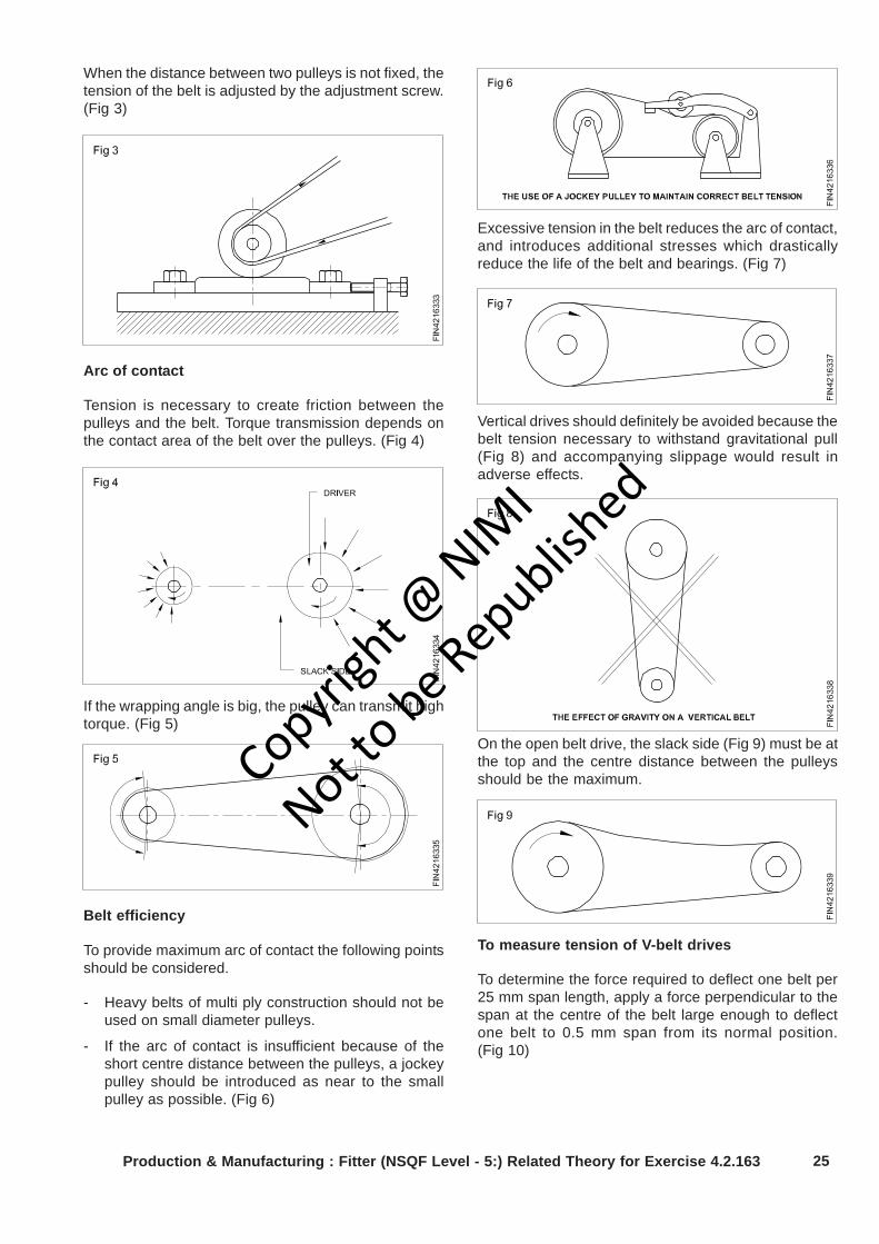
When the distance between two pulleys is not fixed, thetension of the belt is adjusted by the adjustment screw.(Fig 3)
Arc of contact
Tension is necessary to create friction between thepulleys and the belt. Torque transmission depends onthe contact area of the belt over the pulleys. (Fig 4)
If the wrapping angle is big, the pulley can transmit hightorque. (Fig 5)
Belt efficiency
To provide maximum arc of contact the following pointsshould be considered.
- Heavy belts of multi ply construction should not beused on small diameter pulleys.
- If the arc of contact is insufficient because of theshort centre distance between the pulleys, a jockeypulley should be introduced as near to the smallpulley as possible. (Fig 6)
Excessive tension in the belt reduces the arc of contact,and introduces additional stresses which drasticallyreduce the life of the belt and bearings. (Fig 7)
Vertical drives should definitely be avoided because thebelt tension necessary to withstand gravitational pull(Fig 8) and accompanying slippage would result inadverse effects.
On the open belt drive, the slack side (Fig 9) must be atthe top and the centre distance between the pulleysshould be the maximum.
To measure tension of V-belt drives
To determine the force required to deflect one belt per25 mm span length, apply a force perpendicular to thespan at the centre of the belt large enough to deflectone belt to 0.5 mm span from its normal position.(Fig 10)
Copyrigh
t @ NIM
I
Not to be Republish
ed

26 Production & Manufacturing : Fitter (NSQF Level - 5:) Related Theory for Exercise 4.2.163
- Compare this deflection force with the range of forcesgiven in Table 1.
- If it is less than the minimum recommendeddeflection force, the belts should be tightened.
- If it is more than the maximum recommendeddeflection force, the drive is tighter than it need be.
Care and maintenance
- Keep the pulley faces and belts free from foreignmaterial which may cause slips.
- When the ‘V’ belts begin to show signs of wear theyshould be replaced. Replace all the belts in a multiple‘V’ belt drive rather than a single one.
- Check and adjust drive tension periodically.
- Store belts in a cool, dark and dry place.
The belt tension should be adjusted in such a way thatthe deflection force is in between the maximum andminimum.
TABLE 1
Recommended deflection force per belt for classical ‘V’ belts
V-Belt Small Speed Recommended deflectioncross- sheave ratio force Kgsection dia. range range Min. Max.
cm
7.62-8.13 1.08 1.54A 8.64-9.14 2.0-4.0 1.14 1.68
9.65-10.67 1.32 1.9111.68-17.78 1.59 2.26
11.68 2.00 2.86B 12.67-13.71 2.0-4.0 2.22 3.22
14.22-16.25 2.45 3.5317.27-23.87 2.81 4.08
17.78 3.4 5.00C 19.05-20.32 2.0-4.0 3.81 5.44
21.59-25.4 4.30 6.3626.67-40.64 5.00 7.72
30.48-33.02 7.71 10.91D 34.29-39.37 2.0-4.0 8.6 12.27
40.64-55.88 10.00 14.09
E 54.86-60.96 2.0-4.0 14.54 21.36
Copyrigh
t @ NIM
I
Not to be Republish
ed
27Production & Manufacturing : Fitter (NSQF Level - 5:) Related Theory for Exercise 4.2.163
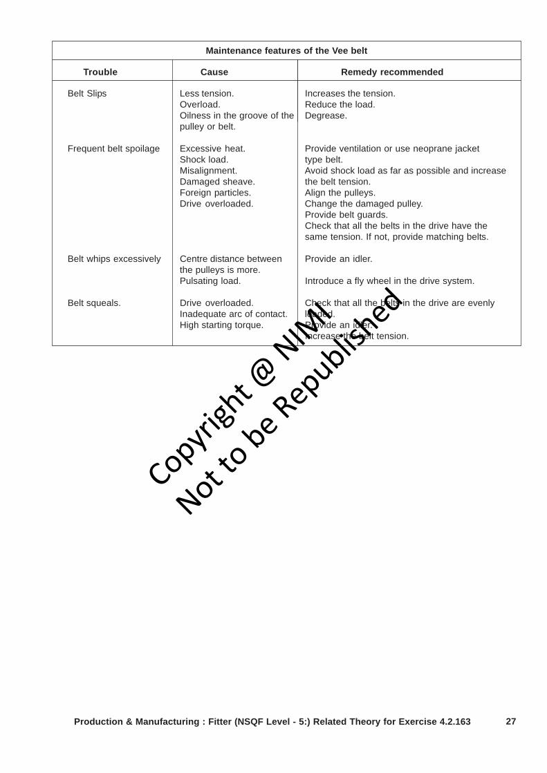
Maintenance features of the Vee belt
Trouble Cause Remedy recommended
Belt Slips Less tension. Increases the tension.Overload. Reduce the load.Oilness in the groove of the Degrease.pulley or belt.
Frequent belt spoilage Excessive heat. Provide ventilation or use neoprane jacketShock load. type belt.Misalignment. Avoid shock load as far as possible and increaseDamaged sheave. the belt tension.Foreign particles. Align the pulleys.Drive overloaded. Change the damaged pulley.
Provide belt guards.Check that all the belts in the drive have thesame tension. If not, provide matching belts.
Belt whips excessively Centre distance between Provide an idler.the pulleys is more.Pulsating load. Introduce a fly wheel in the drive system.
Belt squeals. Drive overloaded. Check that all the belts in the drive are evenlyInadequate arc of contact. loaded.High starting torque. Provide an idler.
Increase the belt tension.
Copyrigh
t @ NIM
I
Not to be Republish
ed
28
Production & Manufacturing Related Theory for Exercise 4.2.164Fitter - Repairing technique
Vee belts and their advantages and disadvantagesObjectives : At the end of this lesson you shall be able to• name of different types of belt• state the advantages of ‘V’ belt• state the classification of ‘V’belt• state the designation of V- belt
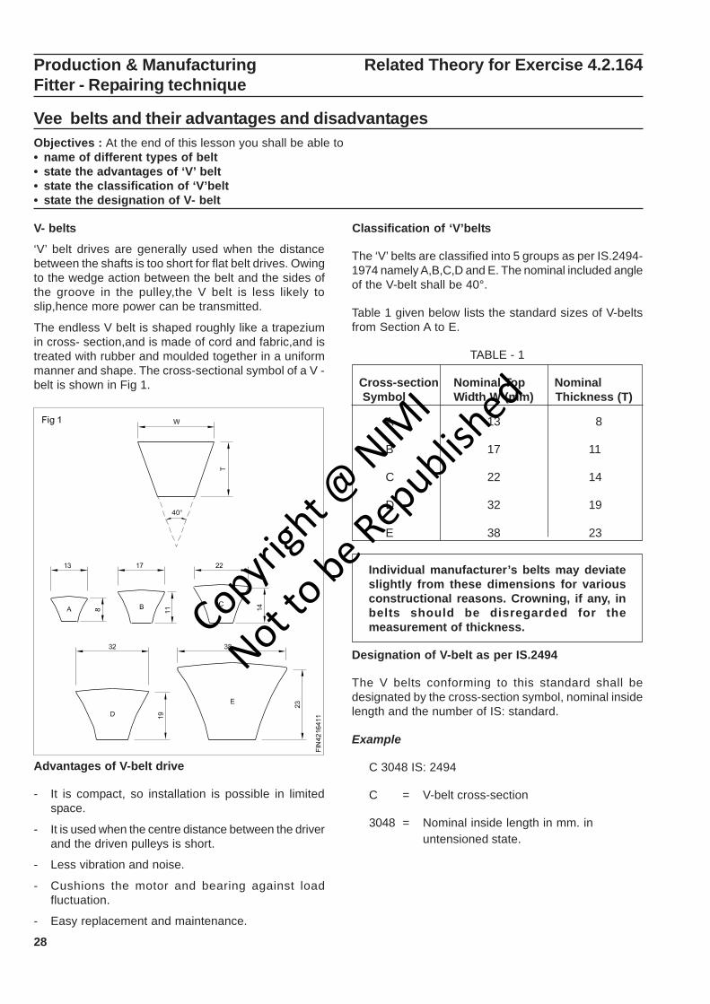
V- belts
‘V’ belt drives are generally used when the distancebetween the shafts is too short for flat belt drives. Owingto the wedge action between the belt and the sides ofthe groove in the pulley,the V belt is less likely toslip,hence more power can be transmitted.
The endless V belt is shaped roughly like a trapeziumin cross- section,and is made of cord and fabric,and istreated with rubber and moulded together in a uniformmanner and shape. The cross-sectional symbol of a V -belt is shown in Fig 1.
Advantages of V-belt drive
- It is compact, so installation is possible in limitedspace.
- It is used when the centre distance between the driverand the driven pulleys is short.
- Less vibration and noise.
- Cushions the motor and bearing against loadfluctuation.
- Easy replacement and maintenance.
Classification of ‘V’belts
The ‘V’ belts are classified into 5 groups as per IS.2494-1974 namely A,B,C,D and E. The nominal included angleof the V-belt shall be 40°.
Table 1 given below lists the standard sizes of V-beltsfrom Section A to E.
TABLE - 1
Cross-section Nominal Top Nominal Symbol Width W (mm) Thickness (T)
A 13 8
B 17 11
C 22 14
D 32 19
E 38 23
Individual manufacturer’s belts may deviateslightly from these dimensions for variousconstructional reasons. Crowning, if any, inbelts should be disregarded for themeasurement of thickness.
Designation of V-belt as per IS.2494
The V belts conforming to this standard shall bedesignated by the cross-section symbol, nominal insidelength and the number of IS: standard.
Example
C 3048 IS: 2494
C = V-belt cross-section
3048 = Nominal inside length in mm. inuntensioned state.
Copyrigh
t @ NIM
I
Not to be Republish
ed
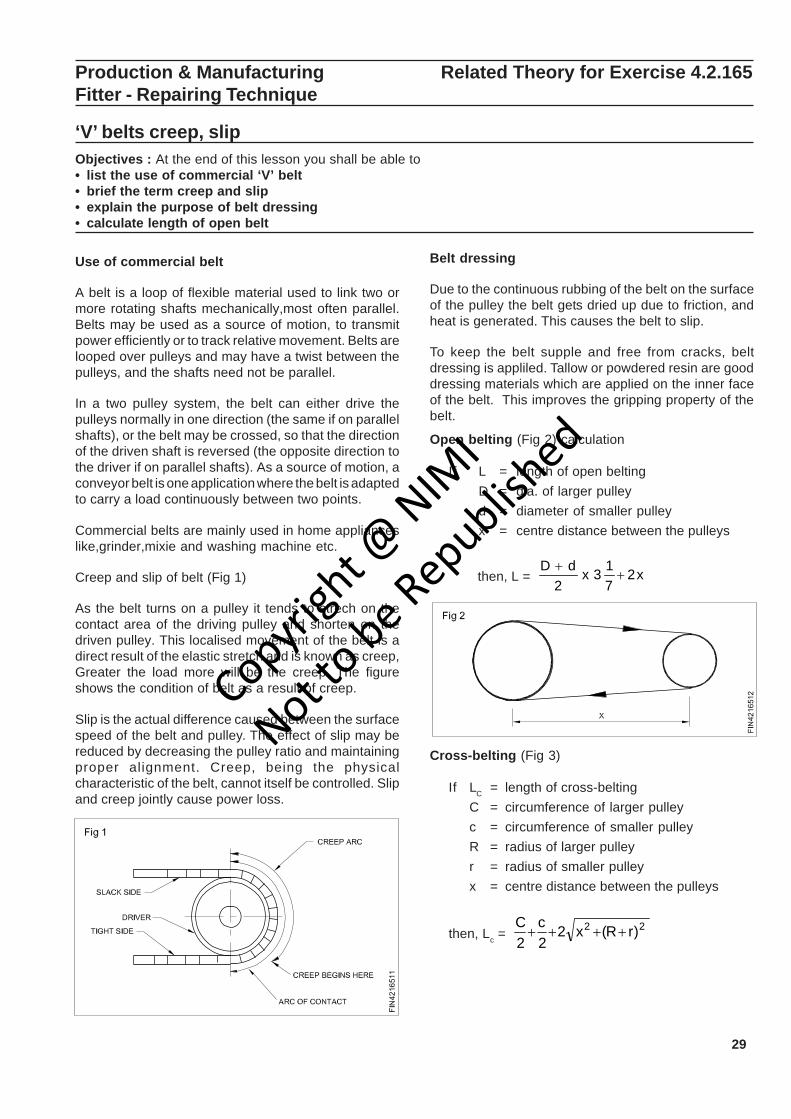
29
Production & Manufacturing Related Theory for Exercise 4.2.165Fitter - Repairing Technique
‘V’ belts creep, slipObjectives : At the end of this lesson you shall be able to• list the use of commercial ‘V’ belt• brief the term creep and slip• explain the purpose of belt dressing• calculate length of open belt
Use of commercial belt
A belt is a loop of flexible material used to link two ormore rotating shafts mechanically,most often parallel.Belts may be used as a source of motion, to transmitpower efficiently or to track relative movement. Belts arelooped over pulleys and may have a twist between thepulleys, and the shafts need not be parallel.
In a two pulley system, the belt can either drive thepulleys normally in one direction (the same if on parallelshafts), or the belt may be crossed, so that the directionof the driven shaft is reversed (the opposite direction tothe driver if on parallel shafts). As a source of motion, aconveyor belt is one application where the belt is adaptedto carry a load continuously between two points.
Commercial belts are mainly used in home applianceslike,grinder,mixie and washing machine etc.
Creep and slip of belt (Fig 1)
As the belt turns on a pulley it tends to strech on thecontact area of the driving pulley and shorten on thedriven pulley. This localised movement of the belt is adirect result of the elastic stretch and is known as creep,Greater the load more will be the creep. The figureshows the condition of belt as a result of creep.
Slip is the actual difference caused between the surfacespeed of the belt and pulley. The effect of slip may bereduced by decreasing the pulley ratio and maintainingproper alignment. Creep, being the physicalcharacteristic of the belt, cannot itself be controlled. Slipand creep jointly cause power loss.
Belt dressing
Due to the continuous rubbing of the belt on the surfaceof the pulley the belt gets dried up due to friction, andheat is generated. This causes the belt to slip.
To keep the belt supple and free from cracks, beltdressing is appliled. Tallow or powdered resin are gooddressing materials which are applied on the inner faceof the belt. This improves the gripping property of thebelt.
Open belting (Fig 2) calculation
If L = length of open beltingD = dia. of larger pulleyd = diameter of smaller pulleyx = centre distance between the pulleys
then, L = x2713x
2dD
++
Cross-belting (Fig 3)
If LC = length of cross-beltingC = circumference of larger pulleyc = circumference of smaller pulleyR = radius of larger pulleyr = radius of smaller pulleyx = centre distance between the pulleys
then, Lc = 22 )rR(x22c
2C
++++
Copyrigh
t @ NIM
I
Not to be Republish
ed
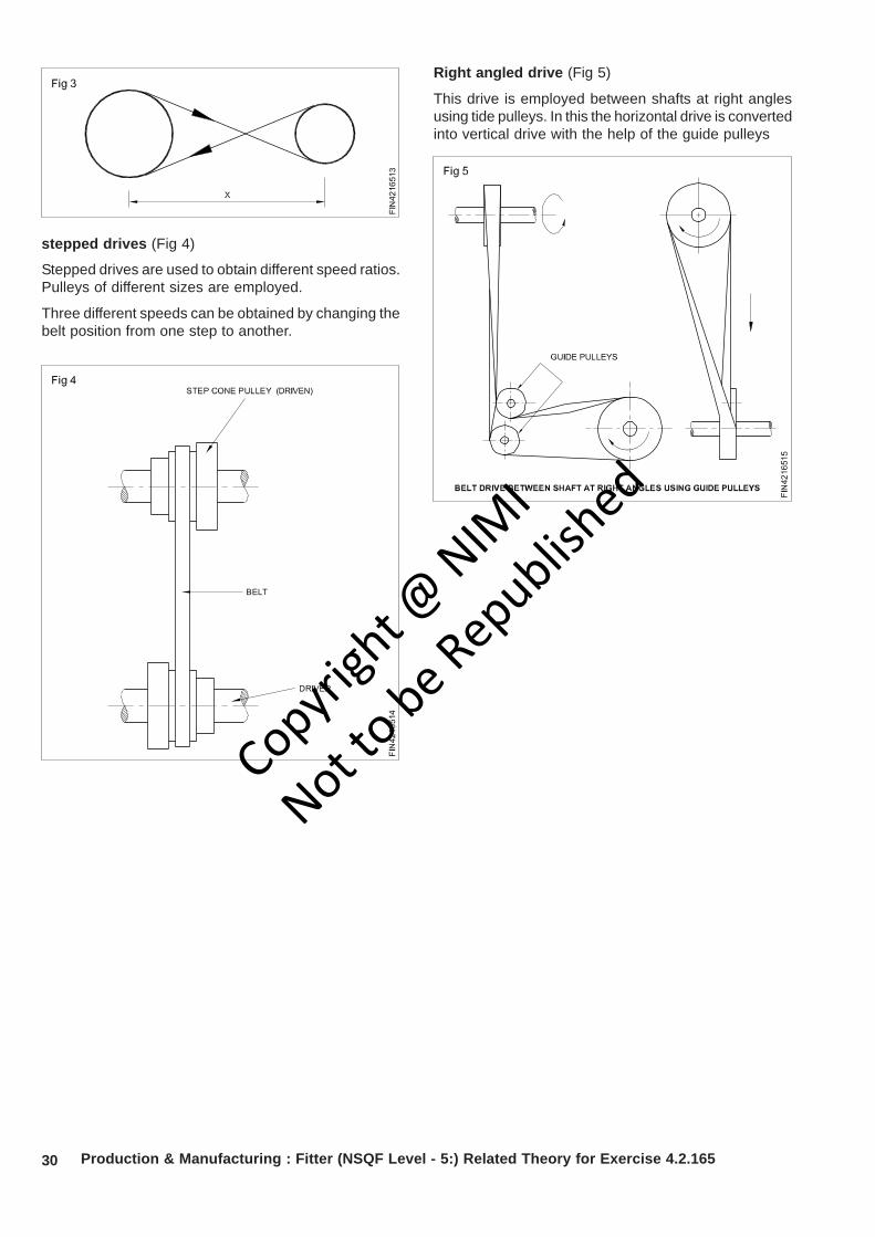
30 Production & Manufacturing : Fitter (NSQF Level - 5:) Related Theory for Exercise 4.2.165
stepped drives (Fig 4)
Stepped drives are used to obtain different speed ratios.Pulleys of different sizes are employed.
Three different speeds can be obtained by changing thebelt position from one step to another.
Right angled drive (Fig 5)
This drive is employed between shafts at right anglesusing tide pulleys. In this the horizontal drive is convertedinto vertical drive with the help of the guide pulleys
Copyrigh
t @ NIM
I
Not to be Republish
ed
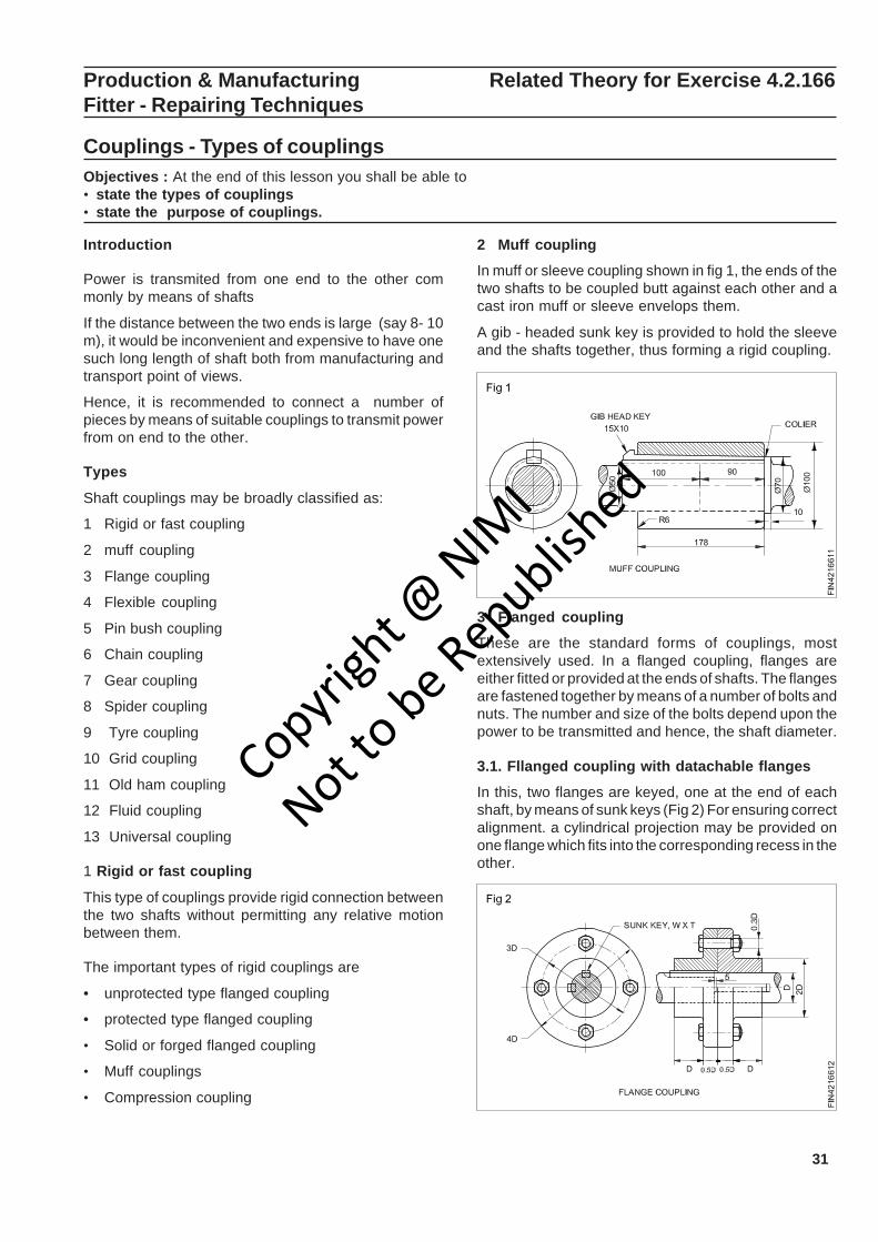
31
Production & Manufacturing Related Theory for Exercise 4.2.166Fitter - Repairing Techniques
Couplings - Types of couplingsObjectives : At the end of this lesson you shall be able to• state the types of couplings• state the purpose of couplings.
Introduction
Power is transmited from one end to the other commonly by means of shafts
If the distance between the two ends is large (say 8- 10m), it would be inconvenient and expensive to have onesuch long length of shaft both from manufacturing andtransport point of views.
Hence, it is recommended to connect a number ofpieces by means of suitable couplings to transmit powerfrom on end to the other.
Types
Shaft couplings may be broadly classified as:
1 Rigid or fast coupling
2 muff coupling
3 Flange coupling
4 Flexible coupling
5 Pin bush coupling
6 Chain coupling
7 Gear coupling
8 Spider coupling
9 Tyre coupling
10 Grid coupling
11 Old ham coupling
12 Fluid coupling
13 Universal coupling
1 Rigid or fast coupling
This type of couplings provide rigid connection betweenthe two shafts without permitting any relative motionbetween them.
The important types of rigid couplings are
• unprotected type flanged coupling
• protected type flanged coupling
• Solid or forged flanged coupling
• Muff couplings
• Compression coupling
2 Muff coupling
In muff or sleeve coupling shown in fig 1, the ends of thetwo shafts to be coupled butt against each other and acast iron muff or sleeve envelops them.
A gib - headed sunk key is provided to hold the sleeveand the shafts together, thus forming a rigid coupling.
3 Flanged coupling
These are the standard forms of couplings, mostextensively used. In a flanged coupling, flanges areeither fitted or provided at the ends of shafts. The flangesare fastened together by means of a number of bolts andnuts. The number and size of the bolts depend upon thepower to be transmitted and hence, the shaft diameter.
3.1. Fllanged coupling with datachable flanges
In this, two flanges are keyed, one at the end of eachshaft, by means of sunk keys (Fig 2) For ensuring correctalignment. a cylindrical projection may be provided onone flange which fits into the corresponding recess in theother.
Copyrigh
t @ NIM
I
Not to be Republish
ed
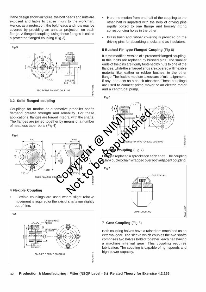
32
In the design shown in figure, the bolt heads and nuts areexposed and liable to cause injury to the workman.Hence, as a protection, the bolt heads and nuts may becovered by providing an annular projection on eachflange. A flanged coupling, using these flanges is calleda protected flanged coupling (Fig 3).
3.2. Solid flanged coupling
Couplings for marine or automotive propeller shaftsdemand greater strength and reliability. For theseapplications, flanges are forged integral with the shafts.The flanges are joined together by means of a numberof headless taper bolts (Fig 4)
4 Flexible Coupling
• Flexible couplings are used where slight relativemovement is required or the axis of shafts run slightlyout of line.
Production & Manufacturing : Fitter (NSQF Level - 5:) Related Theory for Exercise 4.2.166
• Here the motion from one half of the coupling to theother half is imparted with the help of driving pinsrigidly bolted to one flange and loosely fittingcorresponding holes in the other.
• Brass bush and rubber covering is provided on thedriving pins for absorbing shocks and as insulators.
5 Bushed Pin type Flanged Couping (Fig 6)
It is the modified version of a protected flanged coupling.In this, bolts are replaced by bushed pins. The smallerends of the pins are rigidly fastened by nuts to one of theflanges, while the enlarged ends are covered with flexiblematerial like leather or rubber bushes, in the otherflange. The flexible medium takes care of mis - alignment,if any, and acts as a shock absorber. These couplingsare used to connect prime mover or an electric motorand a centrifugal pump.
7 Gear Coupling (Fig 8)
Both coupling halves have a raised rim machined as anexternal gear. The sleeve which couples the two shaftscomprises two halves bolted together, each half havinga machine internal gear. This coupling requireslubrication. The coupling is capable of hgh speeds andhigh power capacity.
6 Chain Coupling (Fig 7)
Flanges replaced a sprocket on each shaft. The couplingis by a duplex chain wrapped over both adjacent coupling.
Copyrigh
t @ NIM
I
Not to be Republish
ed
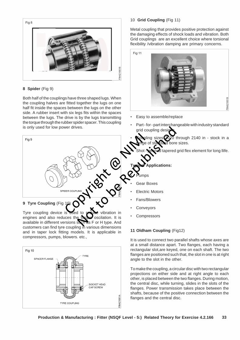
33
8 Spider (Fig 9)
Both half of the couplings have three shaped lugs. Whenthe coupling halves are fitted together the lugs on onehalf fit inside the spaces between the lugs on the otherside. A rubber insert with six legs fits within the spacesbetween the lugs. The drive is by the lugs transmittingthe torque through the rubber spider spacer. This couplingis only used for low power drives.
9 Tyre Coupling (Fig 10)
Tyre coupling device is used to reduce vibration inengines and also reduces the torque oscilation. It isavailable in different versions such as F or H type. Andcustomers can find tyre coupling in various dimensionsand in taper lock fitting models. It is applicable incompressors, pumps, blowers. etc.,
10 Grid Coupling (Fig 11)
Metal coupling that provides positive protection againstthe damaging effects of shock loads and vibration. BothGrid couplings are an excellent choice where torsionalflexibility /vibration damping are primary concerns.
• Easy to assemble/replace
• Part - for - part interchangeable with industry standardgrid coupling designs.
• Coupling sizes 2020 through 2140 in - stock in arange of standard bore sizes.
• Shot - peened tapered grid flex element for long llife.
Typical Applications:
• Pumps
• Gear Boxes
• Electric Motors
• Fans/Blowers
• Conveyors
• Compressors
11 Oldham Coupling (Fig12)
It is used to connect two parallel shafts whose axes areat a small distance apart. Two flanges, each having arectangular slot,are keyed, one on each shaft. The twoflanges are positioned such that, the slot in one is at rightangle to the slot in the other.
To make the coupling, a circular disc with two rectangularprojections on either side and at right angle to eachother, is placed between the two flanges. During motion,the central disc, while turning, slides in the slots of theflanges. Power transmission takes place between theshafts, because of the positive connection between theflanges and the central disc.
Production & Manufacturing : Fitter (NSQF Level - 5:) Related Theory for Exercise 4.2.166
Copyrigh
t @ NIM
I
Not to be Republish
ed
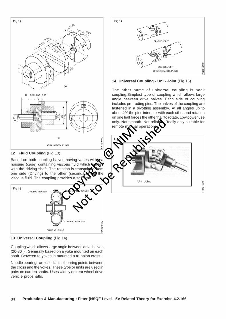
34 Production & Manufacturing : Fitter (NSQF Level - 5): Related Theory for Exercise 4.2.166
12 Fluid Coupling (Fig 13)
Based on both coupling halves having vanes within ahousing (case) containing viscous fluid which rotateswith the driving shaft. The rotation is transmitted fromone side (Driving) to the other (secondary) via theviscous fluid. The coupling provides a soft start.
13 Universal Coupling (Fig 14)
Coupling which allows large angle between drive halves(20-30°) . Generally based on a yoke mounted on eachshaft. Between to yokes in mounted a trunnion cross.
Needle bearings are used at the bearing points betweenthe cross and the yokes. These type or units are used inpairs on carden shafts. Uses widely on rear wheel drivevehicle propshafts.
14 Universal Coupling - Uni - Joint (Fig 15)
The other name of universal coupling is hookcoupling.Simplest type of coupling which allows largeangle between drive halves. Each side of couplingincludes protruding pins. The halves of the coupling arefastened in a pivotting assembly. At all angles up toabout 40° the pins interlock with each other and rotationon one half forces the other half to rotate. Low power useonly. Not smooth. Not reliable. Really only suitable forremote manual operations.
Copyrigh
t @ NIM
I
Not to be Republish
ed
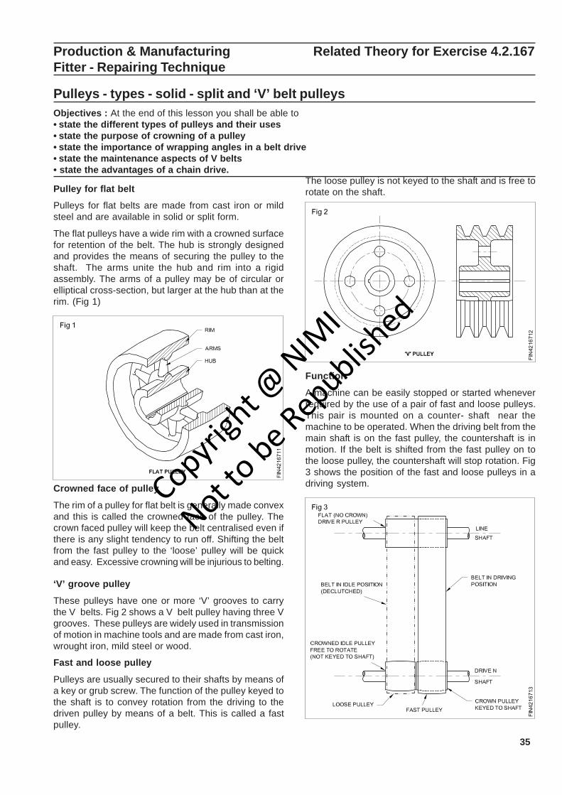
35
Production & Manufacturing Related Theory for Exercise 4.2.167Fitter - Repairing Technique
Pulleys - types - solid - split and ‘V’ belt pulleysObjectives : At the end of this lesson you shall be able to• state the different types of pulleys and their uses• state the purpose of crowning of a pulley• state the importance of wrapping angles in a belt drive• state the maintenance aspects of V belts• state the advantages of a chain drive.
Pulley for flat belt
Pulleys for flat belts are made from cast iron or mildsteel and are available in solid or split form.
The flat pulleys have a wide rim with a crowned surfacefor retention of the belt. The hub is strongly designedand provides the means of securing the pulley to theshaft. The arms unite the hub and rim into a rigidassembly. The arms of a pulley may be of circular orelliptical cross-section, but larger at the hub than at therim. (Fig 1)
Crowned face of pulley
The rim of a pulley for flat belt is generally made convexand this is called the crowned face of the pulley. Thecrown faced pulley will keep the belt centralised even ifthere is any slight tendency to run off. Shifting the beltfrom the fast pulley to the ‘loose’ pulley will be quickand easy. Excessive crowning will be injurious to belting.
‘V’ groove pulley
These pulleys have one or more ‘V’ grooves to carrythe V belts. Fig 2 shows a V belt pulley having three Vgrooves. These pulleys are widely used in transmissionof motion in machine tools and are made from cast iron,wrought iron, mild steel or wood.
Fast and loose pulley
Pulleys are usually secured to their shafts by means ofa key or grub screw. The function of the pulley keyed tothe shaft is to convey rotation from the driving to thedriven pulley by means of a belt. This is called a fastpulley.
The loose pulley is not keyed to the shaft and is free torotate on the shaft.
Function
A machine can be easily stopped or started wheneverrequired by the use of a pair of fast and loose pulleys.This pair is mounted on a counter- shaft near themachine to be operated. When the driving belt from themain shaft is on the fast pulley, the countershaft is inmotion. If the belt is shifted from the fast pulley on tothe loose pulley, the countershaft will stop rotation. Fig3 shows the position of the fast and loose pulleys in adriving system.Copyri
ght @
NIMI
Not to be Republish
ed

36 Production & Manufacturing : Fitter (NSQF Level - 5:) Related Theory for Exercise 4.2.167
Determining the size of crowning faces of pulleyObjectives: This shall help you to• define the importance of crowning• state the specification of standard pulleys.
Crowning one or several pulleys in belt system is themost common way of tracking a belt. For flat powertransmission belts and narow conveyor belts( up to 8in.), a radius crown is used. For wider conveyor belts, atrapezodal crown is typically applied. Note: Never utilizean apex crown!
Radius Crown Specifications for Flat Belt Pulleys
A radius crown represents a great way to track a belt.Dimensionally, it does not take a big crown height inorder for the belt to track properly, and exceeding theseemingly small amounts below will actually do moreharm than good!
In a system with multiple pulleys, crown the pulleys thatturn the same way.
The min. pulley face width
Wp = (belt width W b x 1.1) + 0.5 in.
The max. belt width
Wb = (pulley face width Wp - 0.5 in) / 1.10
in in in in in in in
1-5 0.031 0.047 0.051 0.067 0.078 0.098
5-10 0.039 0.051 0.059 0.078 0.090 0.110
10-16 0.043 0.055 0.063 0.087 0.098 0.118
>16 0.047 0.059 0.078 0.098 0.118 0.137
Convert to metric units
Standard Radius crown heights h
Pulley Diameter DPulley FaceWidth WP 1-6 6-12 12-18 28-40 40-60 >60Copyri
ght @
NIMI
Not to be Republish
ed
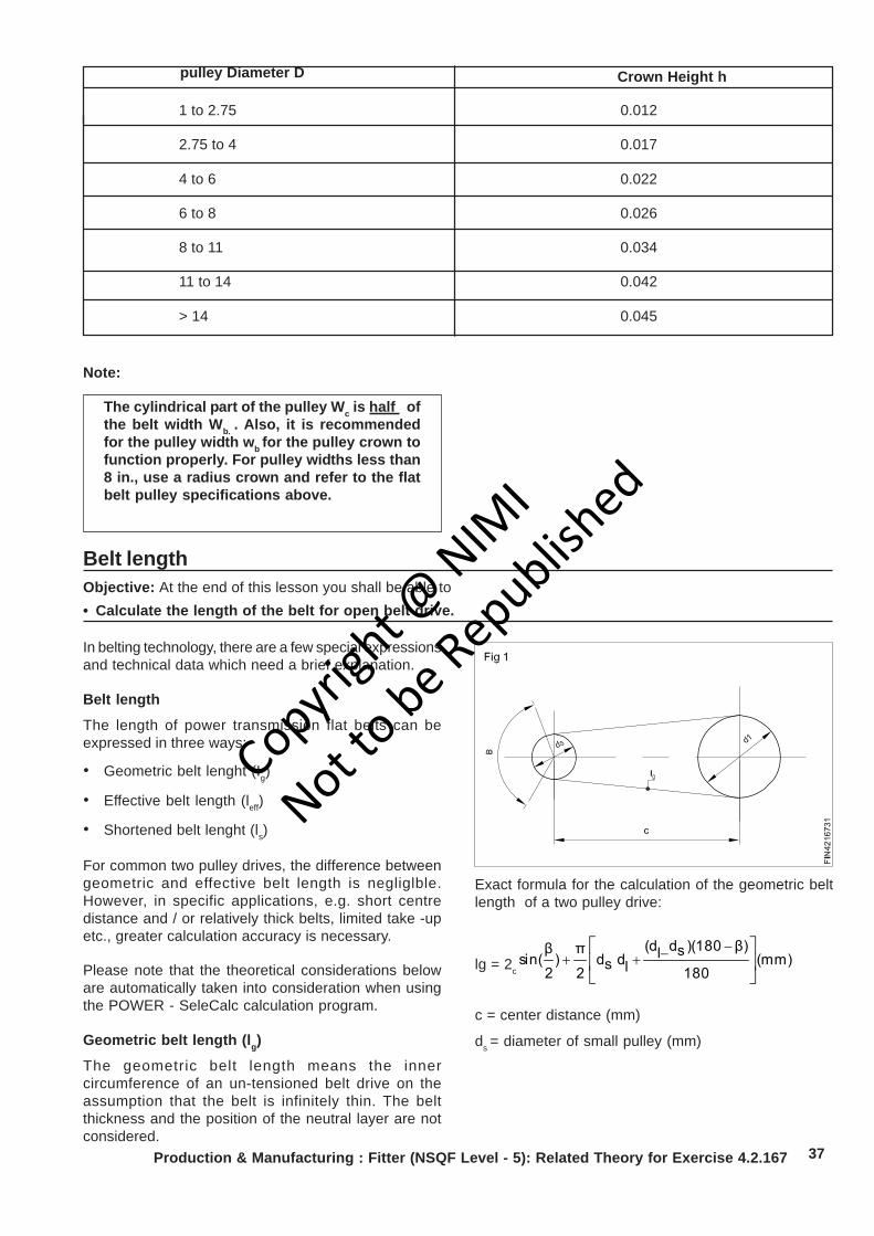
37
1 to 2.75 0.012
2.75 to 4 0.017
4 to 6 0.022
6 to 8 0.026
8 to 11 0.034
11 to 14 0.042
> 14 0.045
Production & Manufacturing : Fitter (NSQF Level - 5): Related Theory for Exercise 4.2.167
Note:
The cylindrical part of the pulley Wc is half ofthe belt width Wb. . Also, it is recommendedfor the pulley width wb
for the pulley crown tofunction properly. For pulley widths less than8 in., use a radius crown and refer to the flatbelt pulley specifications above.
Belt lengthObjective: At the end of this lesson you shall be able to• Calculate the length of the belt for open belt drive.
In belting technology, there are a few special expressionsand technical data which need a brief explanation.
Belt length
The length of power transmission flat belts can beexpressed in three ways:
• Geometric belt lenght (Ig)
• Effective belt length (leff)
• Shortened belt lenght (ls)
For common two pulley drives, the difference betweengeometric and effective belt length is negliglble.However, in specific applications, e.g. short centredistance and / or relatively thick belts, limited take -upetc., greater calculation accuracy is necessary.
Please note that the theoretical considerations beloware automatically taken into consideration when usingthe POWER - SeleCalc calculation program.
Geometric belt length (lg)
The geometric belt length means the innercircumference of an un-tensioned belt drive on theassumption that the belt is infinitely thin. The beltthickness and the position of the neutral layer are notconsidered.
Exact formula for the calculation of the geometric beltlength of a two pulley drive:
lg = 2c (mm)
180
β))(180sdl(dldsd
2
π)
2
βsin( ⎥
⎦
⎤⎢⎣
⎡ −−++
c = center distance (mm)
ds = diameter of small pulley (mm)
pulley Diameter D Crown Height h
Copyrigh
t @ NIM
I
Not to be Republish
ed
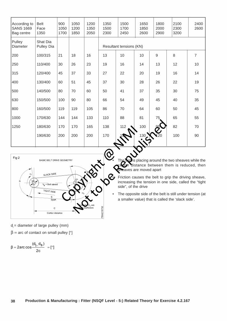
38 Production & Manufacturing : Fitter (NSQF Level - 5:) Related Theory for Exercise 4.2.167
According to Belt 900 1050 1200 1350 1500 1650 1800 2100 2400SANS 1669 Face 1050 1200 1350 1500 1700 1850 2000 2300 2600Bag centre 1350 1700 1850 2050 2300 2450 2600 2900 3200
Pulley Shat DiaDiameter Pulley Dia Resultant tensions (KN)
200 100/315 21 18 16 13 10 10 9 8 7
250 110/400 30 26 23 19 16 14 13 12 10
315 120/400 45 37 33 27 22 20 19 16 14
400 130/400 60 51 45 37 30 28 26 22 19
500 140/500 80 70 60 50 41 37 35 30 75
630 150/500 100 90 80 66 54 49 45 40 35
800 160/500 119 119 105 86 70 64 60 50 45
1000 170/630 144 144 133 110 88 81 75 65 55
1250 180/630 170 170 165 138 112 100 95 82 70
190/630 200 200 200 170 138 130 120 100 90
dl = diameter of large pulley (mm)
β = arc of contact on small pulley [°]
][2c
)sdl(dcos2arc β °=−=
• The belt is placing around the two sheaves while thecenter distance between them is reduced, thensheaves are moved apart
• Friction causes the belt to grip the driving sheave,increasing the tension in one side, called the “tightside”, of the drive
• The opposite side of the belt is still under tension (ata smaller value) that is called the ‘slack side’.Copyri
ght @
NIMI
Not to be Republish
ed
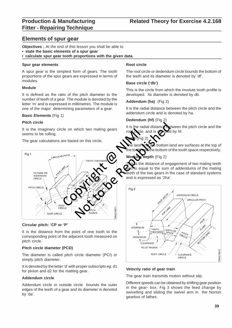
39
Production & Manufacturing Related Theory for Exercise 4.2.168Fitter - Repairing Technique
Elements of spur gearObjectives : At the end of this lesson you shall be able to• state the basic elements of a spur gear• calculate spur gear tooth proportions with the given data.
Spur gear elements
A spur gear is the simplest form of gears. The toothproportions of the spur gears are expressed in terms ofmodules.
Module
It is defined as the ratio of the pitch diameter to thenumber of teeth of a gear. The module is denoted by theletter ‘m’ and is expressed in millimetres. The module isone of the major determining parameters of a gear.
Basic Elements (Fig 1)
Pitch circle
It is the imaginary circle on which two mating gearsseems to be rolling.
The gear calculations are based on this circle.
Circular pitch: ‘CP or ‘P’
It is the distance from the point of one tooth to thecorresponding point of the adjacent tooth measured onpitch circle.
Pitch circle diameter (PCD)
The diameter is called pitch circle diameter (PCI) orsimply pitch diameter.
It is denoted by the letter ‘d’ with proper subscripts eg. d1for pinion and d2 for the matting gear.
Addendum circle
Addendum circle or outside circle bounds the outeredges of the teeth of a gear and its diameter is denotedby ‘da’.
Root circle
The root circle or dedendum circle bounds the bottom ofthe teeth and its diameter is denoted by ‘df’.
Base circle (‘db’)
This is the circle from which the involute tooth profile isdeveloped. Its diameter is denoted by db.
Addendum (ha) (Fig 2)
It is the radial distance between the pitch circle and theaddendum circle and is denoted by ha.
Dedendum (hf) (Fig 2)
It is the radial distance between the pitch circle and theroot circle, and is denoted by hf.
Land (Fig 2)
The land and the bottom land are surfaces at the top ofthe tooth and the bottom of the tooth space respectively.
Working depth (Fig 2)
This is the distance of engagement of two mating teethand is equal to the sum of addendums of the matingteeth of the two gears in the case of standard systemsand is expressed as ‘2ha’.
Velocity ratio of gear train
The gear train transmits motion without slip.
Different speeds can be obtained by shifting gear positionin the gear- box. Fig 3 shows the feed change byswivelling and sliding the swivel arm in the Nortongearbox of lathes.
Copyrigh
t @ NIM
I
Not to be Republish
ed
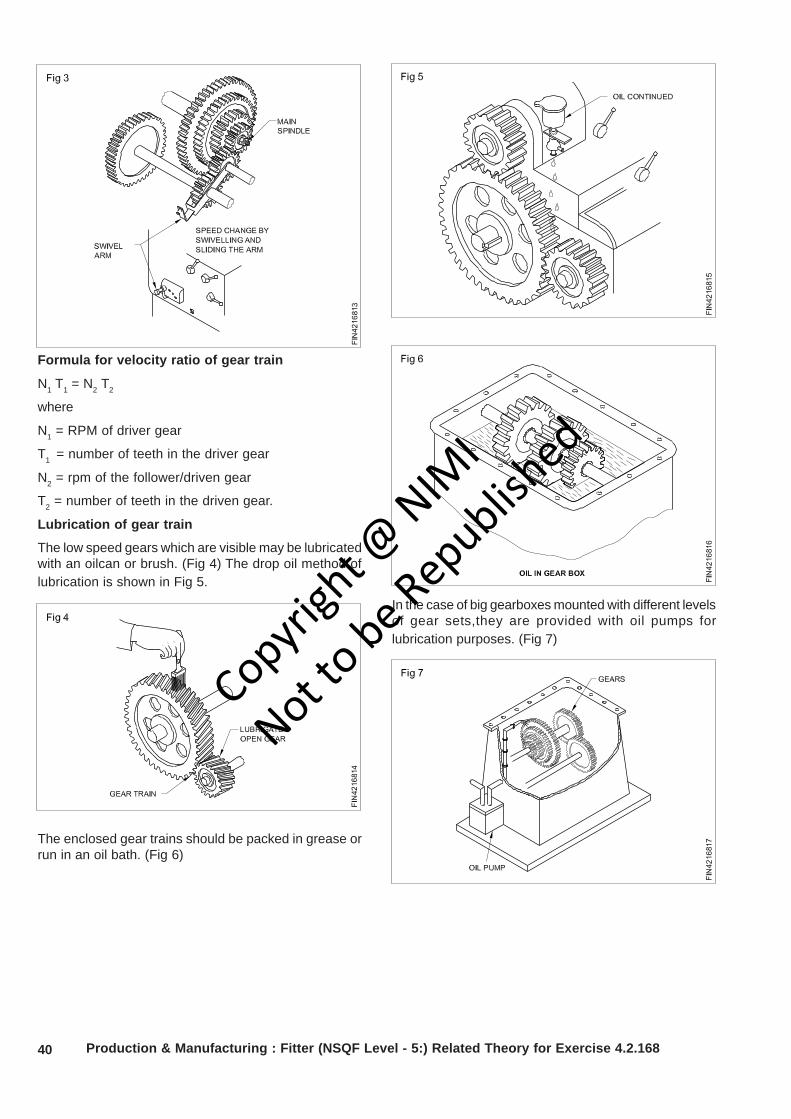
40
Formula for velocity ratio of gear train
N1 T1 = N2 T2
where
N1 = RPM of driver gear
T1 = number of teeth in the driver gear
N2 = rpm of the follower/driven gear
T2 = number of teeth in the driven gear.
Lubrication of gear train
The low speed gears which are visible may be lubricatedwith an oilcan or brush. (Fig 4) The drop oil method oflubrication is shown in Fig 5.
The enclosed gear trains should be packed in grease orrun in an oil bath. (Fig 6)
In the case of big gearboxes mounted with different levelsof gear sets,they are provided with oil pumps forlubrication purposes. (Fig 7)
Production & Manufacturing : Fitter (NSQF Level - 5:) Related Theory for Exercise 4.2.168
Copyrigh
t @ NIM
I
Not to be Republish
ed
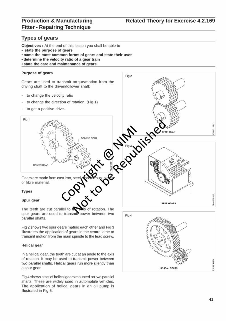
41
Production & Manufacturing Related Theory for Exercise 4.2.169Fitter - Repairing Technique
Types of gearsObjectives : At the end of this lesson you shall be able to• state the purpose of gears• name the most common forms of gears and state their uses• determine the velocity ratio of a gear train• state the care and maintenance of gears.
Purpose of gears
Gears are used to transmit torque/motion from thedriving shaft to the driven/follower shaft:
- to change the velocity ratio
- to change the direction of rotation. (Fig 1)
- to get a positive drive.
Gears are made from cast iron, steel, non-ferrous, plasticor fibre material.
Types
Spur gear
The teeth are cut parallel to the axis of rotation. Thespur gears are used to transmit power between twoparallel shafts.
Fig 2 shows two spur gears mating each other and Fig 3illustrates the application of gears in the centre lathe totransmit motion from the main spindle to the lead screw.
Helical gear
In a helical gear, the teeth are cut at an angle to the axisof rotation. It may be used to transmit power betweentwo parallel shafts. Helical gears run more silently thana spur gear.
Fig 4 shows a set of helical gears mounted on two parallelshafts. These are widely used in automobile vehicles.The application of helical gears in an oil pump isillustrated in Fig 5.
Copyrigh
t @ NIM
I
Not to be Republish
ed

42
The end thrust is exerted by the driving and driven gearsin the case of helical gears and the thrust may beeliminated by using double helical gears. These gearsare called herring-bone gears. (Fig 6)
Bevel gear
The bevel gears shown in Fig 7 are used to transmitmotion between shafts at various angles to each other.The teeth profile may be straight or spiral.
In a hand driller, the bevel gears transmit motion whenthe shafts are at right angles to each other. (Fig 8)
Worm shaft and worm gear
The worm shaft has spiral teeth cut on the shaft and theworm wheel is a special form of gear teeth cut to meshwith the worm shaft. (Fig 10)
Mitre gears
If two bevel gears are symmetrical to each other andtransmit motion at right angles, such gears may be called‘mitre gears’. (Fig 9)
These are widely used for speed reduction purpose.
The application of worm and worm gear in the index-head gear mechanism is shown in Fig 11.
Production & Manufacturing : Fitter (NSQF Level - 5:) Related Theory for Exercise 4.2.169
Copyrigh
t @ NIM
I
Not to be Republish
ed
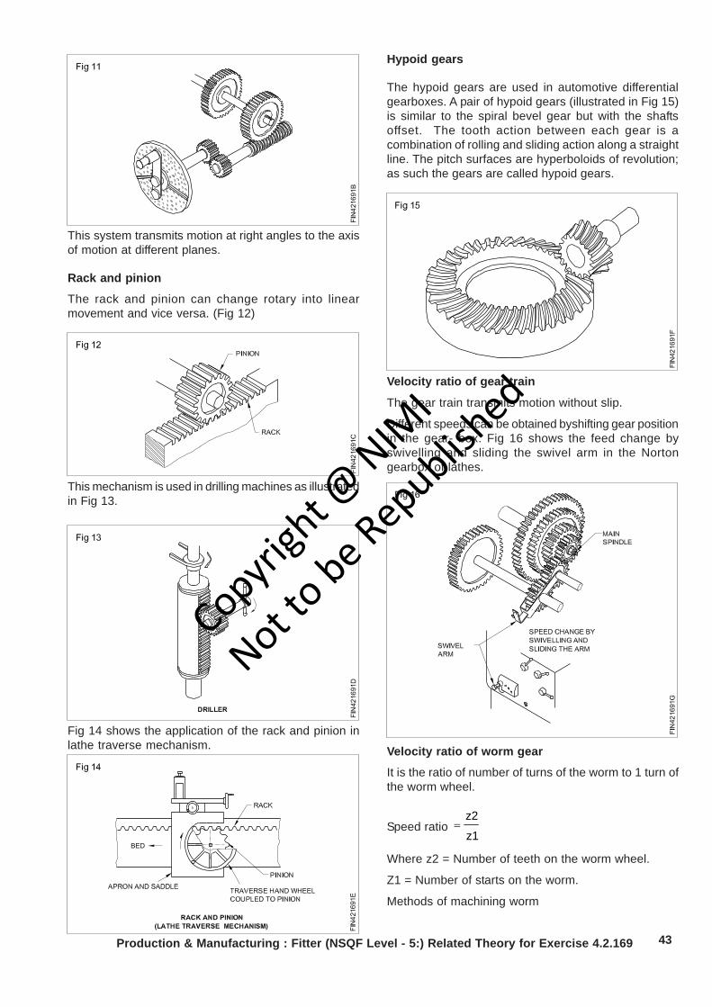
43
This system transmits motion at right angles to the axisof motion at different planes.
Rack and pinion
The rack and pinion can change rotary into linearmovement and vice versa. (Fig 12)
Fig 14 shows the application of the rack and pinion inlathe traverse mechanism.
This mechanism is used in drilling machines as illustratedin Fig 13.
Hypoid gears
The hypoid gears are used in automotive differentialgearboxes. A pair of hypoid gears (illustrated in Fig 15)is similar to the spiral bevel gear but with the shaftsoffset. The tooth action between each gear is acombination of rolling and sliding action along a straightline. The pitch surfaces are hyperboloids of revolution;as such the gears are called hypoid gears.
Velocity ratio of gear train
The gear train transmits motion without slip.
Different speeds can be obtained byshifting gear positionin the gear- box. Fig 16 shows the feed change byswivelling and sliding the swivel arm in the Nortongearbox of lathes.
Velocity ratio of worm gear
It is the ratio of number of turns of the worm to 1 turn ofthe worm wheel.
Speed ratio z1
z2=
Where z2 = Number of teeth on the worm wheel.
Z1 = Number of starts on the worm.
Methods of machining worm
Production & Manufacturing : Fitter (NSQF Level - 5:) Related Theory for Exercise 4.2.169
Copyrigh
t @ NIM
I
Not to be Republish
ed

44
– On a centre lathe
– On a worm milling machine
– On a gear hobbing machine
Methods of machining a wormwheel
– On a milling machine
– On a hobbing machine
Repair broken gear tooth (Dovetail blank method)Objective: At the end of this lesson you shall be able to• repair broken gear tooth by dovetail method.
Support the gear against a Vee block and clamp it byparallel camp.
Mark the dovetail groove on the gear wheel form bothsides using a venier height gauge and vernier bevelprotractor.
Punch the marking lines.(Fig 1)
Drill 3mm dia. relief holes one each on the corner of thedovetail.
Remove material from the gear to shape and size ofdovetail as per marking. (Fig 2)
Production & Manufacturing : Fitter (NSQF Level - 5:) Related Theory for Exercise 4.2.169
File the blank to the profile of the gear tooth as perpunch mark.
File the dovetail portion of the blank.
Fit the blank into the dovetail groove of the gear wheel.If necessary,file the blank till it fits in.
Apply Prussian blue on the dovetail groove to checkthe high spots in the blank piece.
Remove the high spots and make a snug fit in thedovetail groove.
Drill 5.9mm dia. -2 holes up to a depth of 33 mm on theblank and gear wheel in assembled condition.
Ream the holes using a hand reamer.
Dismantle the assemlby and remove the chips fromthe holes of the gear and the blank.
Assemble again and fit the dowel pins in the holes by aslight tapping.
File the profile of the gear tooth to the correct shape.
Use a template to check the profile.
File on the sides of the blank,flush with thegear.
Repair broken gear tooth (Welding method)Objective: At the end of this lesson you shall be able to• repair broken gear tooth using the welding method.
File the broken tooth surface flat. (Fig 1)
Mark for four holes on the surface with 10 mm centredistance between the holes.
Punch the centres for drill holes. (Fig 2)
Drill 5mm dia. holes on the centres to a depth of 9 mm.(Fig 3)
Remove the chips from the holes.
Copyrigh
t @ NIM
I
Not to be Republish
ed
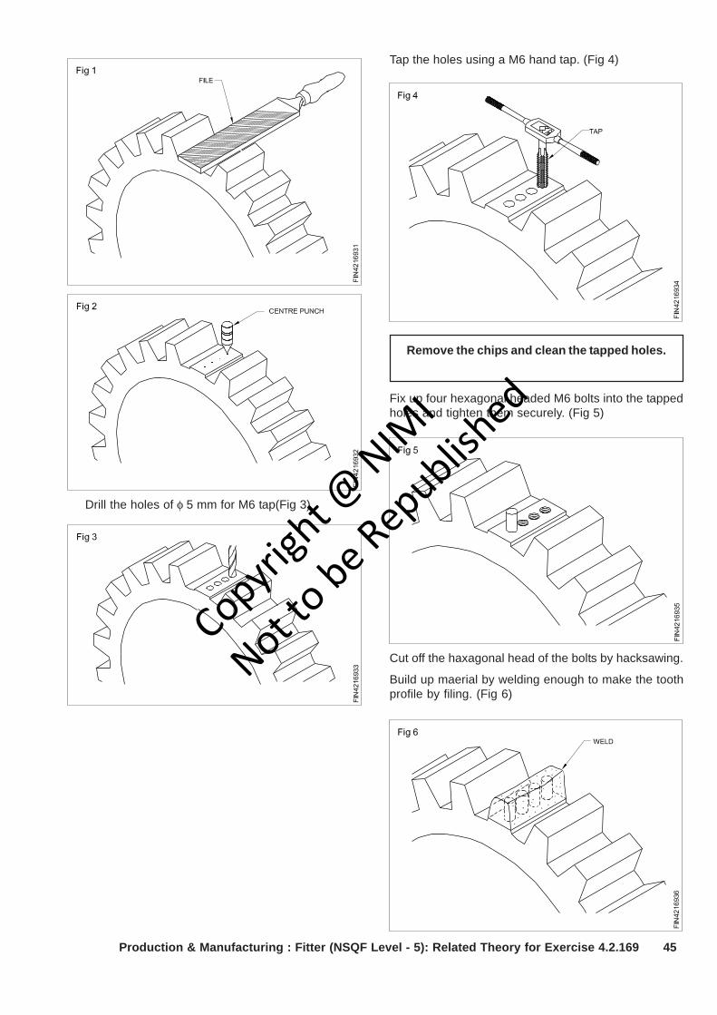
45Production & Manufacturing : Fitter (NSQF Level - 5): Related Theory for Exercise 4.2.169
Drill the holes of φ 5 mm for M6 tap(Fig 3)
Tap the holes using a M6 hand tap. (Fig 4)
Remove the chips and clean the tapped holes.
Fix up four hexagonal headed M6 bolts into the tappedholes and tighten them securely. (Fig 5)
Cut off the haxagonal head of the bolts by hacksawing.
Build up maerial by welding enough to make the toothprofile by filing. (Fig 6)
Copyrigh
t @ NIM
I
Not to be Republish
ed
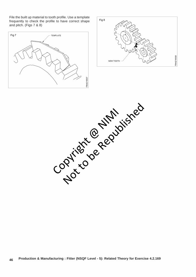
46 Production & Manufacturing : Fitter (NSQF Level - 5): Related Theory for Exercise 4.2.169
File the built up material to tooth profile. Use a templatefrequently to check the profile to have correct shapeand pitch. (Figs 7 & 8)
Copyrigh
t @ NIM
I
Not to be Republish
ed
47
Production & Manufacturing Related Theory for Exercise 4.2.170Fitter - Repairing Technique
Importance of technical English terms used in industriesObjectives : At the end of this lesson you shall be able to• state importance of english for employability skills• state importance of english for soft skills.
English as a language is important for professionalcourses It enhances:
• Employability skills: Trainees who possess the abilityto understand,read,write and speak the language getbetter opportunity to get a job and retain in to scaleheights in their career not only in the corporate,butalso in the public sector.
• Soft skills: Apart from the hard skills that is the abilityto acquire technical skills it has beocme very muchnecessary to master the art of soft skills equally in theunder graduation level to develop the art of articulationin the world of competitive environment when theworld has become very small with the access of
internet and electronic media at our doorsteps.Beingarticulate it would be easier to build interpersonalrelationship for smooth flow of communication toensure productivity. The openness of theenvironement would ensure the confidence in decisionmaking capability. Openness of the ambiance wouldlead to smart work which steer one to be multitasking.
• English as a language gained popularity not until 14 thcentury. Today it is a language of survival andsustenance
• Dominance of the British in every part of the worldduring the 19th and early 20th century by setting upcolonies due to industiral revolution made the languagericher and richest.
Copyrigh
t @ NIM
I
Not to be Republish
ed
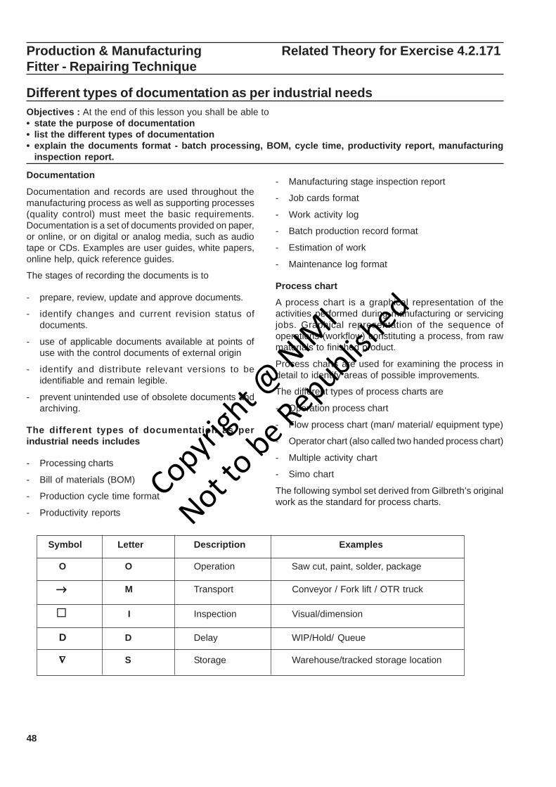
48
Production & Manufacturing Related Theory for Exercise 4.2.171Fitter - Repairing Technique
Different types of documentation as per industrial needsObjectives : At the end of this lesson you shall be able to• state the purpose of documentation• list the different types of documentation• explain the documents format - batch processing, BOM, cycle time, productivity report, manufacturing
inspection report.
Documentation
Documentation and records are used throughout themanufacturing process as well as supporting processes(quality control) must meet the basic requirements.Documentation is a set of documents provided on paper,or online, or on digital or analog media, such as audiotape or CDs. Examples are user guides, white papers,online help, quick reference guides.
The stages of recording the documents is to
- prepare, review, update and approve documents.
- identify changes and current revision status ofdocuments.
- use of applicable documents available at points ofuse with the control documents of external origin
- identify and distribute relevant versions to beidentifiable and remain legible.
- prevent unintended use of obsolete documents andarchiving.
The different types of documentation as perindustrial needs includes
- Processing charts
- Bill of materials (BOM)
- Production cycle time format
- Productivity reports
- Manufacturing stage inspection report
- Job cards format
- Work activity log
- Batch production record format
- Estimation of work
- Maintenance log format
Process chart
A process chart is a graphical representation of theactivities performed during manufacturing or servicingjobs. Graphical representation of the sequence ofoperations (workflow) constituting a process, from rawmaterials to finished product.
Process charts are used for examining the process indetail to identify areas of possible improvements.
The different types of process charts are
- Operation process chart
- Flow process chart (man/ material/ equipment type)
- Operator chart (also called two handed process chart)
- Multiple activity chart
- Simo chart
The following symbol set derived from Gilbreth’s originalwork as the standard for process charts.
Symbol Letter Description Examples
O O Operation Saw cut, paint, solder, package
→→→→→ M Transport Conveyor / Fork lift / OTR truck
I Inspection Visual/dimension
D D Delay WIP/Hold/ Queue
∇ ∇ ∇ ∇ ∇ S Storage Warehouse/tracked storage location
Copyrigh
t @ NIM
I
Not to be Republish
ed
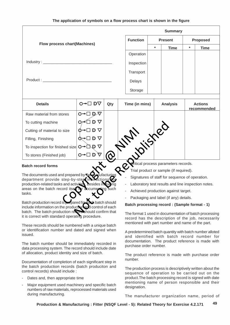
49Production & Manufacturing : Fitter (NSQF Level - 5): Related Theory for Exercise 4.2.171
Summary
Function Present Proposed
* Time * Time Operation
Inspection
Transport
Delays
Storage
Details D Qty Time (in mins) Analysis Actions recommended
Raw material from stores D To cutting machine D Cutting of material to size D Filling, Finishing D To inspection for finished size D To stores (Finished job) D
Flow process chart(Machines)
Industry : ________________________________
Product : ________________________________
The application of symbols on a flow process chart is shown in the figure
Batch record forms
The documents used and prepared by the manufacturingdepartment provide step-by-step instructions forproduction-related tasks and activities, besides includingareas on the batch record itself for documenting suchtasks.
Batch production record is prepared for each batch shouldinclude information on the production and control of eachbatch. The batch production record should confirm thatit is correct with standard operating procedure.
These records should be numbered with a unique batchor identification number and dated and signed whenissued.
The batch number should be immediately recorded indata processing system. The record should include dateof allocation, product identity and size of batch.
Documentation of completion of each significant step inthe batch production records (batch produciton andcontrol records) should include :
- Dates and, then appropriate time
- Major equipment used machinery and specific batchnumbers of raw materials, reprocessed materials usedduring manufacturing.
- Critical process parameters records.
- Trial product or sample (if required).
- Signatures of staff for sequence of operation.
- Laboratory test results and line inspection notes.
- Achieved production against target.
- Packaging and label (if any) details.
Batch processing record : (Sample format - 1)
The format 1 used in documentation of batch processingrecord has the description of the job, necessarilymentioned with part number and name of the part.
A predetermined batch quantity with batch number allotedand identified with batch record number fordocumentation. The product reference is made withpurchase order number.
The product reference is made with purchase ordernumber.
The production process is descriptively written about thesequence of operation to be carried out on theproduct.The batch processing record is signed with datementioning name of person responsible and theirdesignation.
The manufacturer organization name, period of
Copyrigh
t @ NIM
I
Not to be Republish
ed
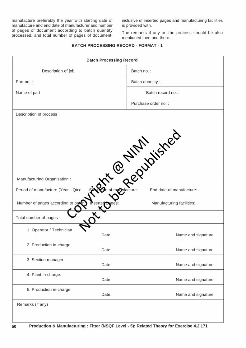
50 Production & Manufacturing : Fitter (NSQF Level - 5): Related Theory for Exercise 4.2.171
manufacture preferably the year with starting date ofmanufacture and end date of manufacturer and numberof pages of document according to batch quantityprocessed, and total number of pages of document,
BATCH PROCESSING RECORD - FORMAT - 1
Batch Processing Record
Description of job Batch no. :
Part no. : Batch quantity :
Name of part : Batch record no. :
Purchase order no. :
Description of process :
Manufacturing Organisation :
Period of manufacture (Year - Qtr): Start date of manufacture: End date of manufacture:
Number of pages according to batch: Inserted pages: Manufacturing facilities:
Total number of pages
1. Operator / TechnicianDate Name and signature
2. Production in-charge:Date Name and signature
3. Section managerDate Name and signature
4. Plant in-charge:Date Name and signature
5. Production in-charge:Date Name and signature
Remarks (if any)
inclusive of inserted pages and manufacturing facilitiesis provided with.
The remarks if any on the process should be alsomentioned then and there.
Copyrigh
t @ NIM
I
Not to be Republish
ed
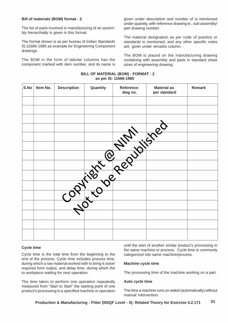
51Production & Manufacturing : Fitter (NSQF Level - 5): Related Theory for Exercise 4.2.171
Bill of materials (BOM) format - 2
The list of parts involved in manufacturing of an assem-bly hierarchially is given in this format.
The format shown is as per bureau of Indian StandardsIS:11666-1985 as example for Engineering Componentdrawings.
The BOM in the form of tabular columns has thecomponent marked with item number, and its name is
given under description and number of is mentionedunder quantity, with reference drawing ie., sub assembly/part drawing number.
The material designation as per code of practice orstandards is mentioned, and any other specific notesare given under remarks column.
The BOM is placed on the manufacturing drawingcontaining with assembly and parts in standard sheetsizes of engineering drawing.
BILL OF MATERIAL (BOM) - FORMAT - 2 as per IS: 11666-1985
S.No Item No. Description Quantity Reference Material as Remark dwg no. per standard
Cycle time
Cycle time is the total time from the beginning to theend of the process. Cycle time includes process time,during which a raw material worked with to bring it closerrequired form output, and delay time, during which theto workpiece waiting for next operation.
The time taken to perform one operation repeatedlymeasured from “Start to Start” the starting point of oneproduct’s processing in a specified machine or operation
until the start of another similar product’s processing inthe same machine or process. Cycle time is commonlycategorized into same machine/process.
Machine cycle time
The processing time of the machine working on a part.
Auto cycle time
The time a machine runs un-aided (automatically) withoutmanual intervention.
Copyrigh
t @ NIM
I
Not to be Republish
ed
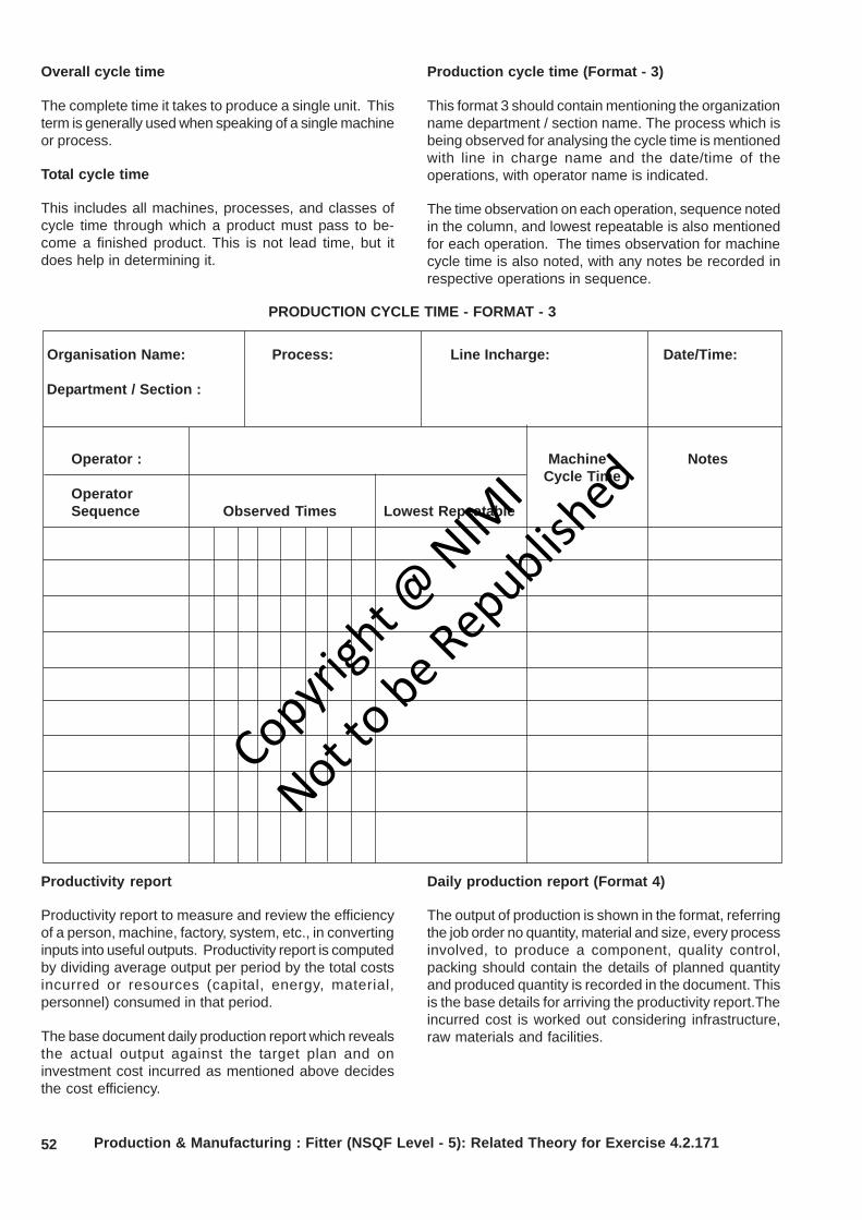
52 Production & Manufacturing : Fitter (NSQF Level - 5): Related Theory for Exercise 4.2.171
Overall cycle time
The complete time it takes to produce a single unit. Thisterm is generally used when speaking of a single machineor process.
Total cycle time
This includes all machines, processes, and classes ofcycle time through which a product must pass to be-come a finished product. This is not lead time, but itdoes help in determining it.
Production cycle time (Format - 3)
This format 3 should contain mentioning the organizationname department / section name. The process which isbeing observed for analysing the cycle time is mentionedwith line in charge name and the date/time of theoperations, with operator name is indicated.
The time observation on each operation, sequence notedin the column, and lowest repeatable is also mentionedfor each operation. The times observation for machinecycle time is also noted, with any notes be recorded inrespective operations in sequence.
PRODUCTION CYCLE TIME - FORMAT - 3
Organisation Name: Process: Line Incharge: Date/Time:
Department / Section :
Operator : Machine NotesCycle Time
OperatorSequence Observed Times Lowest Repeatable
Productivity report
Productivity report to measure and review the efficiencyof a person, machine, factory, system, etc., in convertinginputs into useful outputs. Productivity report is computedby dividing average output per period by the total costsincurred or resources (capital, energy, material,personnel) consumed in that period.
The base document daily production report which revealsthe actual output against the target plan and oninvestment cost incurred as mentioned above decidesthe cost efficiency.
Daily production report (Format 4)
The output of production is shown in the format, referringthe job order no quantity, material and size, every processinvolved, to produce a component, quality control,packing should contain the details of planned quantityand produced quantity is recorded in the document. Thisis the base details for arriving the productivity report.Theincurred cost is worked out considering infrastructure,raw materials and facilities.
Copyrigh
t @ NIM
I
Not to be Republish
ed

53
Dai
ly P
rodu
ctio
n R
epor
t
Dat
e:D
epar
tmen
t:O
rgan
isat
ion
Nam
e:
Sect
ion:
DA
ILY
PRO
DU
CTI
ON
REP
OR
T - F
OR
MA
T- 4
Pro
cess
- I
Pro
cess
-IIP
roce
ss-II
IP
roce
ss-IV
Qua
lity
Con
trol
Pac
king
Pla
nned
Com
plet
edP
lann
edC
ompl
eted
Pla
nned
Com
plet
edP
lann
edC
ompl
eted
Pla
nned
Com
plet
edP
lann
edC
ompl
eted
Job
Ord
er N
o.Q
uant
ityM
ater
ial &
Siz
e
Job
Ord
er N
o.Q
uant
ityM
ater
ial &
Siz
e
Job
Ord
er N
o.Q
uant
ityM
ater
ial &
Siz
e
Job
Ord
er N
o.Q
uant
ityM
ater
ial &
Siz
e
Job
Ord
er N
o.Q
uant
ityM
ater
ial &
Siz
e
Sig
natu
re o
f sec
tion
Inch
arge
Production & Manufacturing : Fitter (NSQF Level - 5): Related Theory for Exercise 4.2.171
Copyrigh
t @ NIM
I
Not to be Republish
ed

54 Production & Manufacturing : Fitter (NSQF Level - 5): Related Theory for Exercise 4.2.171
Manufacturing stage inspection report (Format 5)
The format 5 is to monitor the production in variousstages for which manufacturing stage inspectionconducted for documentation to review the productivity.The format gives the details of product being inspectedshowing the details of customer reference by purchase
order (PO) number and date, job order number and date,process involved in manufacture of product, the qualitysubmitted for inspection. The accepted and rejectedquality recorded with inspection record review date andthe inspection person signature who conducted the stageinspection is recorded date wise for mentioned /specifiedperiod with start and end dates.
Insp
ectio
n R
ecor
d N
o.
Org
anis
atio
n N
ame
:
St
atus
: F
rom
Dat
e ...
./....
/.....
. To
Dat
e ...
/.../.
.....
Date
Product ID/ Code
Customer
P.O No. &Date
Job OrderNo.
J.O Date
Process
Qty
Accepted
Rejected
Insp
ectio
n c
ondu
cted
by
MA
NU
FAC
TUR
ING
STA
GE
INSP
ECTI
ON
REP
OR
T - F
OR
MAT
- 5
Copyrigh
t @ NIM
I
Not to be Republish
ed

55
Production & Manufacturing Related Theory for Exercise 4.2.172Fitter - Repairing Technique
Documentations - 2Objectives : At the end of this lesson you shall be able to• state the purpose of job card and its format details• explain work activity log format details• state the details of batch production format.
Job card
A job card is a document showing the details of a job tobe performed in a production shop. It is used to authorizeand instruct the work team to take up the productionwork.
Job card format - 1
Job card has the details of commencing the job,customer name, work order no, document number,reference number and date.
The details which have to be recorded about the productline description showing the operations each intorecording of start time and total time of operation. Thelocation time recorded is to track if any delay/ reasonsand necessary actions if taken with remarks.
If the product has to be completed with any of the furtheroperations in sequence, this card will travel along withjob for next workstations for further operations if any tocomplete the requirement of job, and recorded tillfinishing of the job.
Doc No.
Job Card Rev No.
Date
Order Starting Date
Customer
Work Order No.
Details
S.No. Date Production Line Time (Minutes) Location Remarks Description Start Time End Time Total Time Time
JOB CARD - FORMAT-1
Copyrigh
t @ NIM
I
Not to be Republish
ed
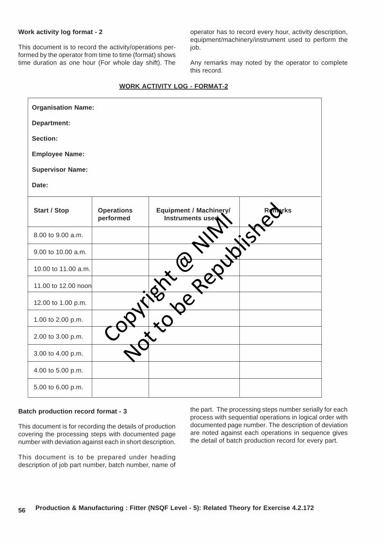
56
Work activity log format - 2
This document is to record the activity/operations per-formed by the operator from time to time (format) showstime duration as one hour (For whole day shift). The
operator has to record every hour, activity description,equipment/machinery/instrument used to perform thejob.
Any remarks may noted by the operator to completethis record.
Organisation Name:
Department:
Section:
Employee Name:
Supervisor Name:
Date:
Start / Stop Operations Equipment / Machinery/ Remarksperformed Instruments used
8.00 to 9.00 a.m.
9.00 to 10.00 a.m.
10.00 to 11.00 a.m.
11.00 to 12.00 noon
12.00 to 1.00 p.m.
1.00 to 2.00 p.m.
2.00 to 3.00 p.m.
3.00 to 4.00 p.m.
4.00 to 5.00 p.m.
5.00 to 6.00 p.m.
WORK ACTIVITY LOG - FORMAT-2
Batch production record format - 3
This document is for recording the details of productioncovering the processing steps with documented pagenumber with deviation against each in short description.
This document is to be prepared under headingdescription of job part number, batch number, name of
the part. The processing steps number serially for eachprocess with sequential operations in logical order withdocumented page number. The description of deviationare noted against each operations in sequence givesthe detail of batch production record for every part.
Production & Manufacturing : Fitter (NSQF Level - 5): Related Theory for Exercise 4.2.172
Copyrigh
t @ NIM
I
Not to be Republish
ed

57
BATCH PRODUCTION RECORD - FORMAT-3
Batch Production Record in accordance with batch processing record
Manufacturing Organisation Name: _______________________
Description of job: ______________________
Name of part: __________________________
Batch No.: ____________________________
The following deviations have appeared (continued)
No. process Name of processing step Documented Short description step page no. of deviation
1 Raw material preparation:
Operation 1: Descaling 1. _____________
Operation 2: Degreasing 2. _____________
Operation 3: Wire brushing 3. _____________4. _____________
2 Sizing of material:
Operation 1: Shearing 1. _____________
Operation 2: Deburring 2. _____________3. _____________
Estimation and maintenance recordsObjectives : At the end of this lesson you shall be able to• state the purpose of estimation• explain the details of formats for estimation sheet• explain the details of formats for maintenance log, history sheet of machinery and equipment and checklist
for preventive maintenance.
Estimation is the method of calculating the variousquantities and the expenditure to be incurred on aparticular job or process.
In case the funds available are less than the estimatedcost the work is done in part or by reducing it orspecifications are altered,
The following essential details are required for preparingan estimate.
Drawings like plan, elevation and sections of importantparts.
Detailed specifications about workmanship & propertiesof materials, etc.
Standard schedule of rates of the current year.
Estimating is the process of preparing an approximationof quantities which is a value used as input data and it isderived from the best information available.
An estimate that turns out to be incorrect will be anoverestimate if the estimate exceeded the actual result,and an underestimate if the estimate fell short of theactual result.
A cost estimate contains approximate cost of a productprocess or operation. The cost estimate has a single totalvalue and it is inclusive of identifiable componentvalues.
Production & Manufacturing : Fitter (NSQF Level - 5): Related Theory for Exercise 4.2.172
Copyrigh
t @ NIM
I
Not to be Republish
ed
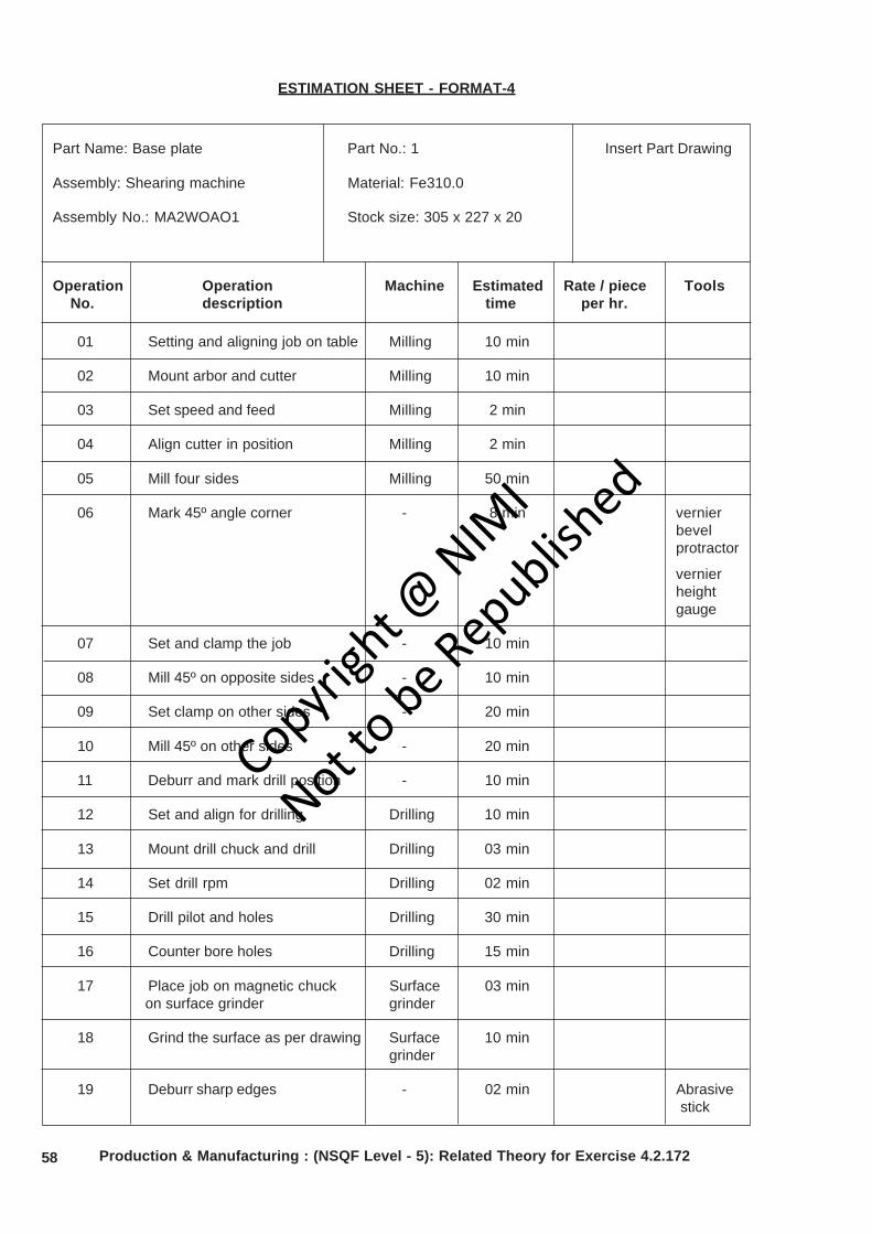
58
Part Name: Base plate Part No.: 1 Insert Part Drawing
Assembly: Shearing machine Material: Fe310.0
Assembly No.: MA2WOAO1 Stock size: 305 x 227 x 20
Operation Operation Machine Estimated Rate / piece Tools No. description time per hr.
01 Setting and aligning job on table Milling 10 min
02 Mount arbor and cutter Milling 10 min
03 Set speed and feed Milling 2 min
04 Align cutter in position Milling 2 min
05 Mill four sides Milling 50 min
06 Mark 45º angle corner - 8 min vernierbevelprotractor
vernierheightgauge
07 Set and clamp the job - 10 min
08 Mill 45º on opposite sides - 10 min
09 Set clamp on other sides - 20 min
10 Mill 45º on other sides - 20 min
11 Deburr and mark drill position - 10 min
12 Set and align for drilling Drilling 10 min
13 Mount drill chuck and drill Drilling 03 min
14 Set drill rpm Drilling 02 min
15 Drill pilot and holes Drilling 30 min
16 Counter bore holes Drilling 15 min
17 Place job on magnetic chuck Surface 03 min on surface grinder grinder
18 Grind the surface as per drawing Surface 10 mingrinder
19 Deburr sharp edges - 02 min Abrasive stick
ESTIMATION SHEET - FORMAT-4
Production & Manufacturing : (NSQF Level - 5): Related Theory for Exercise 4.2.172
Copyrigh
t @ NIM
I
Not to be Republish
ed

59
Maintenance log - Format 5This format is made with details of maintenance activitiesperformed machinewise,
Production & Manufacturing : Fitter (NSQF Level - 5): Related Theory for Exercise 4.2.172
MAINTENANCE LOG - FORMAT - 5
Organisation Name :
Department:
Section:
Name of the machine:
S.No Date Nature of fault Details of rectification done Signature of in-charge
Copyrigh
t @ NIM
I
Not to be Republish
ed

60
History sheet of machinery equipment - Format 6The document recorded with historical data about themachinery and equipment, contains all details aboutsupplier address, order no., date of receipt, installedand placed, Date of commissioning and machine
dimensions, weight, cost, particulars of drive motor,spare partsdetails, belt specification, lubrication details, majorrepair/ overhauls done with dates recorded then andthere for analysing the functional and frequency ofbreakdown etc.,
MACHINERY AND EQUIPMENT RECORD FORMAT - 6
Organisation Name :
Department:
Section:
History sheet of machinery & Equipement
Description of equipment
Manufacturer’s address
Supplier’s address
Order No. and date
Date on which received
Date on which installed and place
Size : Length x Width x Height
Weight
Cost
Motor particular Watts/ H.P./ r.p.m: phase: Volts:
Bearings/ spares/ record
Belt specification
Lubrication details
Major repairs and overhauls carried out with dates
Production & Manufacturing : Fitter (NSQF Level - 5): Related Theory for Exercise 4.2.172
Copyrigh
t @ NIM
I
Not to be Republish
ed

61
Checklist for preventive maintenance inspection -Format 7
The very essential document required to observe, thefunctional aspects of each parts, defects and theremedial measures taken is recorded.
This format enables to program the frequency ofmaintenance schedules so as to minimise frequentbreakdown of machinery/equipments.
PREVENTIVE MAINTENANCE RECORD - FORMAT 7
Organisation Name :
Department :
Section :
Name of the Machine :
Machine Number :
Model No & Make :
Check list for machine inspection
Inspect the following items and tick in the appropriate column and list the remedial measures for thedefective items.
Items to be checked Good working Satisfactory Defective Remedial measures
Level of the machine
Belt/chain and its tension
Bearing condition (Look, feel, Listen noise)
Driving clutch and brake
Exposed gears
Working in all the speeds
Working in all feeds
Lubrication and its system
Carriage & its travel
Cross-slide & its movement
Compound slide & its travel
Tailstock’s parallel movement
Electrical controls
Safety guards
Inspected by :
Signature :
Name :
Date : Signature of in-charge
Production & Manufacturing : Fitter (NSQF Level - 5): Related Theory for Exercise 4.2.172
Copyrigh
t @ NIM
I
Not to be Republish
ed
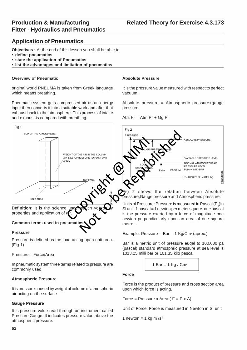
62
Production & Manufacturing Related Theory for Exercise 4.3.173Fitter - Hydraulics and Pneumatics
Application of PneumaticsObjectives : At the end of this lesson you shall be able to• define pneumatics• state the application of Pneumatics• list the advantages and limitation of pneumatics
Overview of Pneumatic
original world PNEUMA is taken from Greek languagewhich means breathing.
Pneumatic system gets compressed air as an energyinput then converts it into a suitable work and after thatexhaust back to the atmosphere. This process of intakeand exhaust is compared with breathing.
Definition: It is the science under which you studyproperties and application of air.
Common terms used in pneumatics
Pressure
Pressure is defined as the load acting upon unit area.(Fig 1)
Pressure = Force/Area
In pneumatic system three terms related to pressure arecommonly used.
Atmospheric Pressure
It is pressure caused by weight of column of atmosphericair acting on the surface
Gauge Pressure
It is pressure value read through an instrument calledPressure Gauge. It indicates pressure value above theatmospheric pressure.
Absolute Pressure
It is the pressure value measured with respect to perfectvacuum.
Absolute pressure = Atmospheric pressure+gaugepressure
Abs Pr = Atm Pr + Gg Pr
Fig 2 shows the relation between Absolutepressure,Gauge pressure and Atmospheric pressure.
Units of Pressure: Pressure is measured in Pascal (Pa)inSI unit. 1 pascal = 1 newton per meter square. one pascalis the pressure exerted by a force of magnitude onenewton perpendicularly upon an area of one squaremetre...
Example: Pressure = Bar = 1 Kg/Cm2 (aprox.)
Bar is a metric unit of pressure euqal to 100,000 pa(pascal) standard atmosphric pressure at sea level is1013.25 milli bar or 101.35 kilo pascal
1 Bar = 1 Kg / Cm2
Force
Force is the product of pressure and cross section areaupon which force is acting.
Force = Pressure x Area ( F = P x A)
Unit of Force: Force is measured in Newton in SI unit
1 newton = 1 kg m /s2
Copyrigh
t @ NIM
I
Not to be Republish
ed
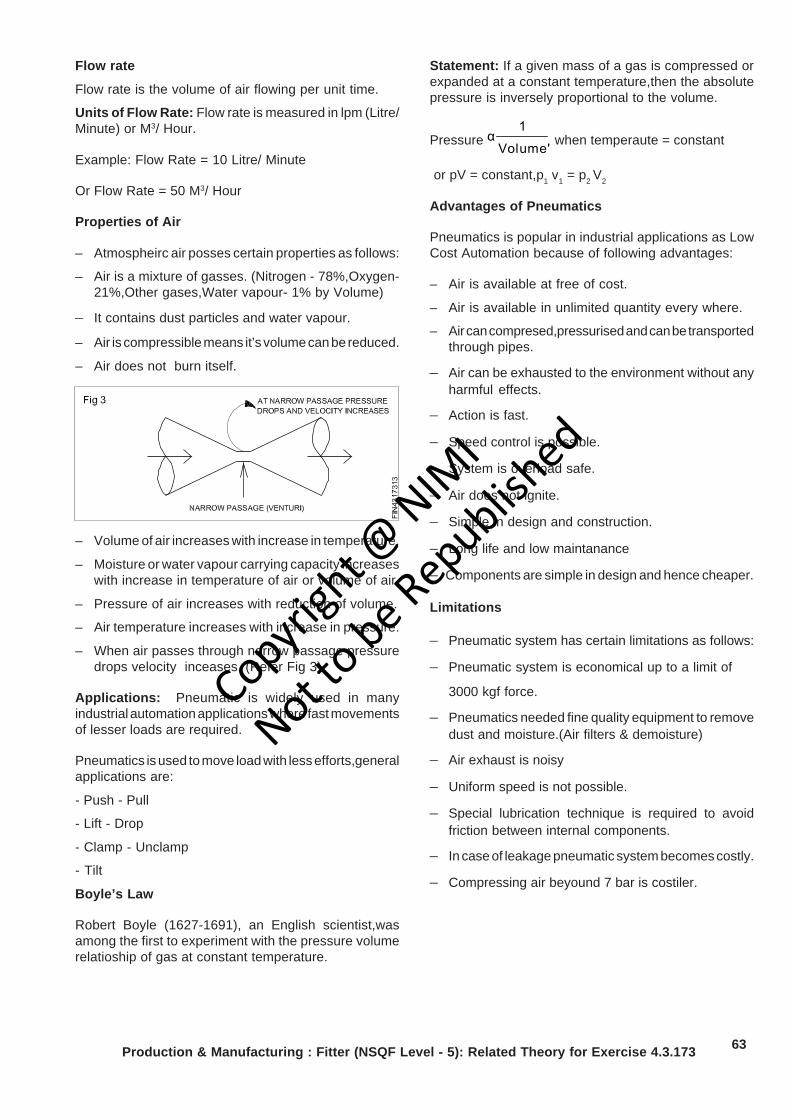
63Production & Manufacturing : Fitter (NSQF Level - 5): Related Theory for Exercise 4.3.173
Flow rate
Flow rate is the volume of air flowing per unit time.
Units of Flow Rate: Flow rate is measured in lpm (Litre/Minute) or M3/ Hour.
Example: Flow Rate = 10 Litre/ Minute
Or Flow Rate = 50 M3/ Hour
Properties of Air
– Atmospheirc air posses certain properties as follows:
– Air is a mixture of gasses. (Nitrogen - 78%,Oxygen-21%,Other gases,Water vapour- 1% by Volume)
– It contains dust particles and water vapour.
– Air is compressible means it’s volume can be reduced.
– Air does not burn itself.
– Volume of air increases with increase in temperature.
– Moisture or water vapour carrying capacity increaseswith increase in temperature of air or volume of air.
– Pressure of air increases with reduction of volume.
– Air temperature increases with increase in pressure.
– When air passes through narrow passage pressuredrops velocity inceases. (Refer Fig 3)
Applications: Pneumatic is widely used in manyindustrial automation applications where fast movementsof lesser loads are required.
Pneumatics is used to move load with less efforts,generalapplications are:
- Push - Pull
- Lift - Drop
- Clamp - Unclamp
- Tilt
Boyle’s Law
Robert Boyle (1627-1691), an English scientist,wasamong the first to experiment with the pressure volumerelatioship of gas at constant temperature.
Statement: If a given mass of a gas is compressed orexpanded at a constant temperature,then the absolutepressure is inversely proportional to the volume.
Pressure Volume'
1α when temperaute = constant
or pV = constant,p1 v1 = p2 V2
Advantages of Pneumatics
Pneumatics is popular in industrial applications as LowCost Automation because of following advantages:
– Air is available at free of cost.
– Air is available in unlimited quantity every where.
– Air can compresed,pressurised and can be transportedthrough pipes.
– Air can be exhausted to the environment without anyharmful effects.
– Action is fast.
– Speed control is possible.
– System is overload safe.
– Air does not ignite.
– Simple in design and construction.
– Long life and low maintanance
– Components are simple in design and hence cheaper.
Limitations
– Pneumatic system has certain limitations as follows:
– Pneumatic system is economical up to a limit of
3000 kgf force.
– Pneumatics needed fine quality equipment to removedust and moisture.(Air filters & demoisture)
– Air exhaust is noisy
– Uniform speed is not possible.
– Special lubrication technique is required to avoidfriction between internal components.
– In case of leakage pneumatic system becomes costly.
– Compressing air beyound 7 bar is costiler.
Copyrigh
t @ NIM
I
Not to be Republish
ed
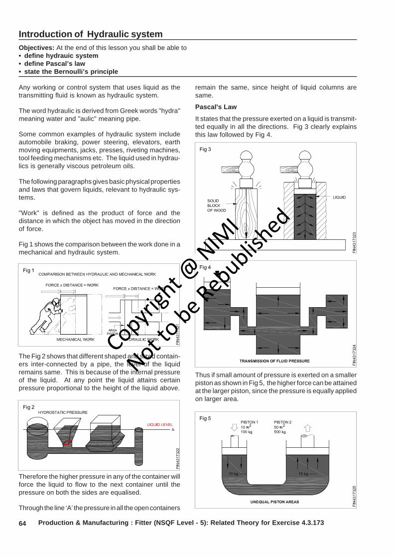
64 Production & Manufacturing : Fitter (NSQF Level - 5): Related Theory for Exercise 4.3.173
Introduction of Hydraulic systemObjectives: At the end of this lesson you shall be able to• define hydrauic system• define Pascal’s law• state the Bernoulli’s principle
Any working or control system that uses liquid as thetransmitting fluid is known as hydraulic system.
The word hydraulic is derived from Greek words "hydra"meaning water and "aulic" meaning pipe.
Some common examples of hydraulic system includeautomobile braking, power steering, elevators, earthmoving equipments, jacks, presses, riveting machines,tool feeding mechanisms etc. The liquid used in hydrau-lics is generally viscous petroleum oils.
The following paragraphs gives basic physical propertiesand laws that govern liquids, relevant to hydraulic sys-tems.
"Work" is defined as the product of force and thedistance in which the object has moved in the directionof force.
Fig 1 shows the comparison between the work done in amechanical and hydraulic system.
The Fig 2 shows that different shaped and sized contain-ers inter-connected by a pipe, the level of the liquidremains same. This is because of the internal pressureof the liquid. At any point the liquid attains certainpressure proportional to the height of the liquid above.
Therefore the higher pressure in any of the container willforce the liquid to flow to the next container until thepressure on both the sides are equalised.
Through the line ‘A’ the pressure in all the open containers
remain the same, since height of liquid columns aresame.
Pascal's Law
It states that the pressure exerted on a liquid is transmit-ted equally in all the directions. Fig 3 clearly explainsthis law followed by Fig 4.
Thus if small amount of pressure is exerted on a smallerpiston as shown in Fig 5, the higher force can be attainedat the larger piston, since the pressure is equally appliedon larger area.
Copyrigh
t @ NIM
I
Not to be Republish
ed
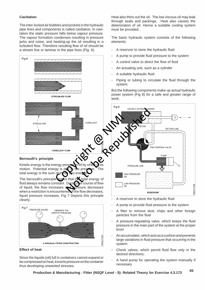
65Production & Manufacturing : Fitter (NSQF Level - 5): Related Theory for Exercise 4.3.173
Bernoulli's principle
Kinetic energy is the energy present in oil by virtue of itsmotion. Potential energy is due to the pressure. Thetotal energy is the sum of these two energies.
The bernoulli's principle states that the total energy offluid always remains constant. During the course of flowof liquid, the flow increases and pressure decreaseswhen a restriction is encountered. If the flow decreases,liquid pressure increases. Fig 7 Depicts this principleclearly.
Heat also thins out the oil. The low viscous oil may leakthrough seals and packings. Heat also causes thedeterioration of oil. Hence a suitable cooling systemmust be provided.
The basic hydraulic system consists of the followingelements:
- A reservoir to store the hydraulic fluid
- A pump to provide fluid pressure to the system
- A control valve to direct the flow of fluid
- An actuating unit, such as a cylinder
- A suitable hydraulic fluid
- Piping or tubing to circulate the fluid through thesystem.
But the following components make up actual hydraulicpower system (Fig 8) for a safe and greater range ofwork.
Cavitation
The inter-locked air bubbles and pockets in the hydraulicpipe lines and components is called cavitation. In cavi-tation the static pressure falls below vapour pressure.The vapour formation condenses resulting in pressurejerks and noise, and heating-up the oil resulting in aturbulent flow. Therefore resulting flow of oil should bea stream line or laminar in the pipe lines (Fig. 6).
Effect of heat
Since the liquids (oil) full in containers cannot expand orbe compressed on heat, it exerts pressure on the containerthus developing unwanted stresses.
- A reservoir to store the hydraulic fluid
- A pump to provide fluid pressure to the system
- A filter to remove dust, chips and other foreignparticles from the fluid
- A pressure-regulating valve, which keeps the fluidpressure in the main part of the system at the properlevel
- An accumulator, which acts as a cushion and preventslarge variations in fluid pressure that occurring in thesystem
- Check valves, which permit fluid flow only in thedesired directions.
- A hand pump for operating the system manually ifnecessary
Copyrigh
t @ NIM
I
Not to be Republish
ed
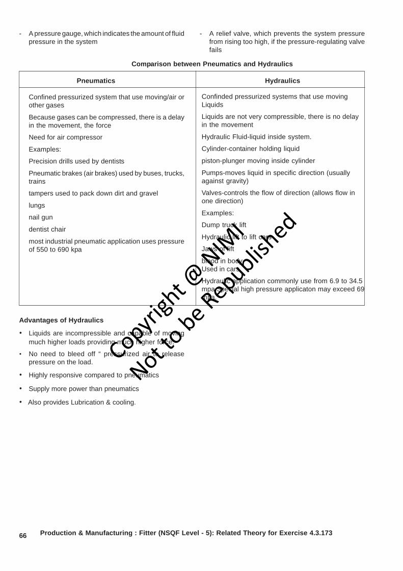
66 Production & Manufacturing : Fitter (NSQF Level - 5): Related Theory for Exercise 4.3.173
- A pressure gauge, which indicates the amount of fluidpressure in the system
- A relief valve, which prevents the system pressurefrom rising too high, if the pressure-regulating valvefails
Comparison between Pneumatics and Hydraulics
Confinded pressurized systems that use movingLiquids
Liquids are not very compressible, there is no delayin the movement
Hydraulic Fluid-liquid inside system.
Cylinder-container holding liquid
piston-plunger moving inside cylinder
Pumps-moves liquid in specific direction (usuallyagainst gravity)
Valves-controls the flow of direction (allows flow inone direction)
Examples:
Dump truck lift
Hydraulic lift to lift cars
Jaws of lift
blood in bodyUsed in cars
Hydraulic application commonly use from 6.9 to 34.5mpa.Special high pressure applicaton may exceed 69mpa.
Advantages of Hydraulics
• Liquids are incompressible and capable of movingmuch higher loads providing much higher force.
• No need to bleed off “ pressurized air to releasepressure on the load.
• Highly responsive compared to pneumatics
• Supply more power than pneumatics
• Also provides Lubrication & cooling.
Pneumatics Hydraulics
Confined pressurized system that use moving/air orother gases
Because gases can be compressed, there is a delayin the movement, the force
Need for air compressor
Examples:
Precision drills used by dentists
Pneumatic brakes (air brakes) used by buses, trucks,trains
tampers used to pack down dirt and gravel
lungs
nail gun
dentist chair
most industrial pneumatic application uses pressureof 550 to 690 kpa
Copyrigh
t @ NIM
I
Not to be Republish
ed
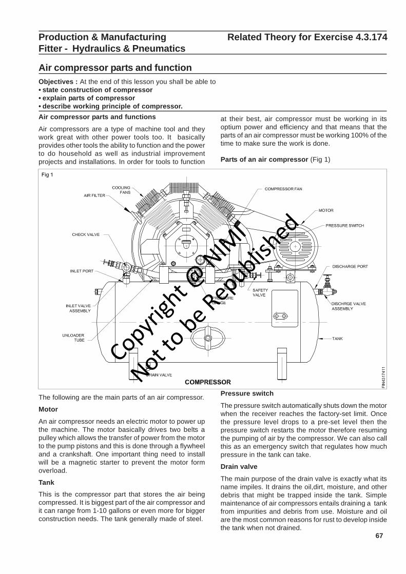
67
Production & Manufacturing Related Theory for Exercise 4.3.174Fitter - Hydraulics & Pneumatics
Air compressor parts and functionObjectives : At the end of this lesson you shall be able to• state construction of compressor• explain parts of compressor• describe working principle of compressor.Air compressor parts and functions
Air compressors are a type of machine tool and theywork great with other power tools too. It basicallyprovides other tools the ability to function and the powerto do household as well as industrial improvementprojects and installations. In order for tools to function
at their best, air compressor must be working in itsoptium power and efficiency and that means that theparts of an air compressor must be working 100% of thetime to make sure the work is done.
Parts of an air compressor (Fig 1)
The following are the main parts of an air compressor.
Motor
An air compressor needs an electric motor to power upthe machine. The motor basically drives two belts apulley which allows the transfer of power from the motorto the pump pistons and this is done through a flywheeland a crankshaft. One important thing need to installwill be a magnetic starter to prevent the motor formoverload.
TankThis is the compressor part that stores the air beingcompressed. It is biggest part of the air compressor andit can range from 1-10 gallons or even more for biggerconstruction needs. The tank generally made of steel.
Pressure switch
The pressure switch automatically shuts down the motorwhen the receiver reaches the factory-set limit. Oncethe pressure level drops to a pre-set level then thepressure switch restarts the motor therefore resumingthe pumping of air by the compressor. We can also callthis as an emergency switch that regulates how muchpressure in the tank can take.
Drain valve
The main purpose of the drain valve is exactly what itsname impiles. It drains the oil,dirt, moisture, and otherdebris that might be trapped inside the tank. Simplemaintenance of air compressors entails draining a tankfrom impurities and debris from use. Moisture and oilare the most common reasons for rust to develop insidethe tank when not drained.
Copyrigh
t @ NIM
I
Not to be Republish
ed
68 Production & Manufacturing : Fitter (NSQF Level - 5): Related Theory for Exercise 4.3.174
Pressure gauge
This gauge measures compressed air pressure in thetank of the air compressor. It lets the user know thatthere is a problem if the measurement is higher thanthe regulated normal limit and serves as a warning toinspect the air compressor or stop the compressionbefore the gauge reaches even higher pressure. On thecontrary if the reading is very low from the normalallowed measurement, it also indicates a problem withthe compressor such as a leak in the tank. This shouldalso be checked right away to avoid any morecomplications and accidents.
Inlet port
This port is used to guide the inlet air towards thecompressor inlet valve.
Inlet valve assembly
Inlet valve assembly compromises valve plate, andvalve spring. Inlet valve controls the flow of air towardsthe cylinder of compressor. It is opening downwards toallow the air inside when the piston moves downwards.Valve plate is used to hold the inlet valve in properposition.
Cooling fins
Cooling fins are the extended part provided from thecylinder body to assure heat transfer from cylinder tosurrounding.Generally these are made of aluminum.
Discharge Port
It is the opening provided at the top of compressorcylinder to guide discharge air towards the dischargeline.
Discharge vavle assembly
It comprises discharge valve plate, valve plate and valvespring. Valve plate helps to hold the discharge valve inproper position. Valve is aimed for discharge the highpressure air when the piston reaches its top.
Air filter
Air filter is very important part in an air compressor. Ithelps to prevent the dirt and dust to enter inside thecompressor cylinder. Filter is provided in the suctionend of the compressor.
Safety valve
A safety valve is provided on the air storage tank or airoutlet line ro prevent the danger occurred when the airpressure reaches beyond the capability of storage tankcapacity.
Regulator
Generally an air regulator is provided in the dischargetube to regulate the high pressure air flow.
Check valve/Non return valve (NRV) and unloadertube
An one way check valve is provided in the bypass linein between air receiver tank and compressor head. Itwill open and admit the high pressure air towards thereceiver tank while unloading is going on during thestarting time. An unloader tube is connected at the inletport of the check valve and the valve only opens in onedirection (ie from compressor top to receiver air flow).During this time the high pressure air is unloaded towardstank through unloader tube.
Compressor fan
A compressor fan is connected at one end of the crankshaft to provide sufficient cooling air to compressor. Itwill prevent overheating of compressor.
Air compressor working principle
Working principle (Fig 1)
Air compressors collect and store air in a pressurizedtank, and use pistons and valves to achieve theappropriate pressure levels within and air storages tankthat is attached to the motorized unit. There are a fewdifferent types of piston compressors that can delivereven air pressures to the user.
Automotive compressors are combustion enginecompressors that use the up-and-down storke of thepiston to allow air in and pressurize the air with in thestorage tank. Other piston compressors utilize adiaphragm, oil-free piston. These pull air in, andpressurize it by not allowing air to escape during thecollection period.
Now the air compressor is capable of building extremepressure in storage tanks capable of storing enormousamounts of pressurized gases for industrial use.
Air dryer
A compressed air dryer is used for removing water vaporfrom compressed air.
Compressed air dryers commonly found in a wide rangeof industrial commercial facilities.
Usage
Drying air for use in commercial or industrial processesthat demand dry air:
Telecom industry (pressurizes its underground cablesto repel moisture and avoid shorts).
Copyrigh
t @ NIM
I
Not to be Republish
ed
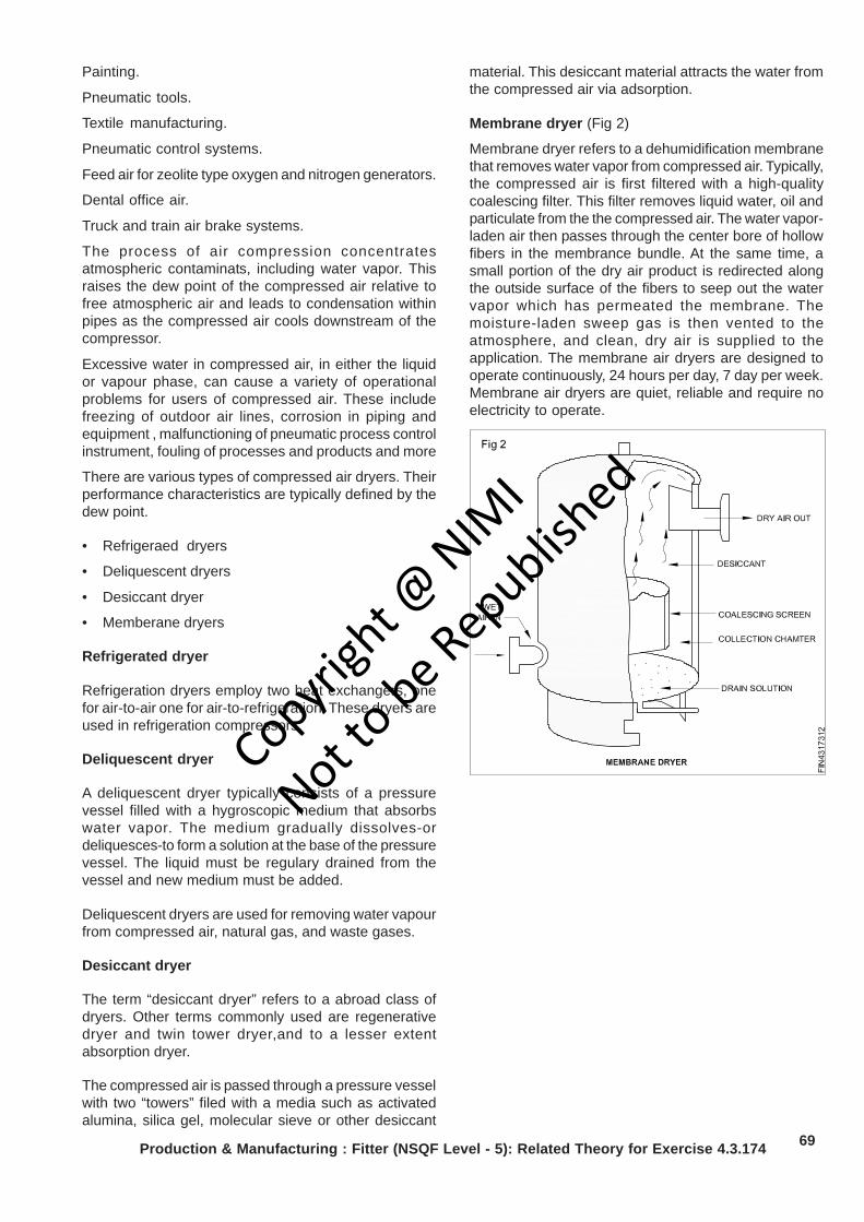
69
Painting.
Pneumatic tools.
Textile manufacturing.
Pneumatic control systems.
Feed air for zeolite type oxygen and nitrogen generators.
Dental office air.
Truck and train air brake systems.
The process of air compression concentratesatmospheric contaminats, including water vapor. Thisraises the dew point of the compressed air relative tofree atmospheric air and leads to condensation withinpipes as the compressed air cools downstream of thecompressor.
Excessive water in compressed air, in either the liquidor vapour phase, can cause a variety of operationalproblems for users of compressed air. These includefreezing of outdoor air lines, corrosion in piping andequipment , malfunctioning of pneumatic process controlinstrument, fouling of processes and products and more
There are various types of compressed air dryers. Theirperformance characteristics are typically defined by thedew point.
• Refrigeraed dryers
• Deliquescent dryers
• Desiccant dryer
• Memberane dryers
Refrigerated dryer
Refrigeration dryers employ two heat exchangers, onefor air-to-air one for air-to-refrigeration. These dryers areused in refrigeration compressors.
Deliquescent dryer
A deliquescent dryer typically consists of a pressurevessel filled with a hygroscopic medium that absorbswater vapor. The medium gradually dissolves-ordeliquesces-to form a solution at the base of the pressurevessel. The liquid must be regulary drained from thevessel and new medium must be added.
Deliquescent dryers are used for removing water vapourfrom compressed air, natural gas, and waste gases.
Desiccant dryer
The term “desiccant dryer” refers to a abroad class ofdryers. Other terms commonly used are regenerativedryer and twin tower dryer,and to a lesser extentabsorption dryer.
The compressed air is passed through a pressure vesselwith two “towers” filed with a media such as activatedalumina, silica gel, molecular sieve or other desiccant
Production & Manufacturing : Fitter (NSQF Level - 5): Related Theory for Exercise 4.3.174
material. This desiccant material attracts the water fromthe compressed air via adsorption.
Membrane dryer (Fig 2)
Membrane dryer refers to a dehumidification membranethat removes water vapor from compressed air. Typically,the compressed air is first filtered with a high-qualitycoalescing filter. This filter removes liquid water, oil andparticulate from the the compressed air. The water vapor-laden air then passes through the center bore of hollowfibers in the membrance bundle. At the same time, asmall portion of the dry air product is redirected alongthe outside surface of the fibers to seep out the watervapor which has permeated the membrane. Themoisture-laden sweep gas is then vented to theatmosphere, and clean, dry air is supplied to theapplication. The membrane air dryers are designed tooperate continuously, 24 hours per day, 7 day per week.Membrane air dryers are quiet, reliable and require noelectricity to operate.
Copyrigh
t @ NIM
I
Not to be Republish
ed
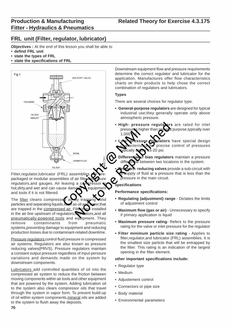
70
Production & Manufacturing Related Theory for Exercise 4.3.175Fitter - Hydraulics & Pneumatics
FRL unit (Filter, regulator, lubricator)Objectives : At the end of this lesson you shall be able to• defind FRL unit• state the types of FRL• state the specifications of FRL
Fitter,regulator,lubricator (FRL) assemblies are pre-packaged or modular assemblies of air filters,pressureregulators,and gauges. Air leaving a compressor ishot,dirty,and wet and can cause damage to equipmentand tools if it is not filtered.
The filter cleans compressed air by trapping solidparticles and separating liquids,such as oil and water,thatare trapped in the compressed air. Filters are installedin the air line upstream of regulators,lubricators,and allpneumatically-powered tools and equipment. Theyremove contaminants from pneumaticsystems,preventing damage to equipment and reducingproduction losses due to contaminant-related downtime.
Pressure regulators control fluid pressure in compressedair systems. Regulators are also known as pressurereducing valves(PRVS). Pressure regulators maintaina constant output pressure regardless of input perssurevariations and demands made on the system bydownstream components.
Lubricators add controlled quantities of oil into thecompressed air system to reduce the friction betweenmoving components within air tools and other equipmentthat are powered by the system. Adding lubrication oilto the system also clears compressor oils that travelthrough the system in vapor form. To prevent build-upof oil within system components,mineral oils are addedto the system to flush away the deposits.
Downstream equipment flow and pressure requirementsdetermine the correct regulator and lubricator for theapplication. Manufactures offer flow characteristicscharts on their products to help chose the correctcombination of regulators and lubricators.
Types
There are several choices for regulator type.
• General-purpose regulators are designed for typicalindustrial use;they generally operate only aboveatmospheric pressure.
• High- pressure regulators are rated for inletpressures higher than general purpose,typically over1,000 psi.
• Low- pressure regulators have special designcharacteristics for precise control of pressurestypically below 15-20 psi.
• Differential or bias regulators maintain a pressuredifferential between two locations in the system.
• Pressure- reducing valves provide a sub-circuit witha supply of fluid at a pressure that is less than thepressure in the main circuit.
specifications
Performance specifications:
• Regulating (adjustment) range - Dictates the limitsof adjustment control
• Maximum flow (gas or air) - Unnecessary to specifyif primary application is liquid
• Maximum pressure rating- Refers to the pressurerating for the valve or inlet pressure for the regulator
• Filter minimum particle size rating - Applies tofilter,regulator,and lubricator (FRL) assemblies. It isthe smallest size particle that will be entrapped bythe filter. This rating is an indication of the largestopening in the filter element.
other important specifications include:
• Regulator type
• Medium
• Adjustement control
• Connectors or pipe size
• Body material
• Environmental parameters
Copyrigh
t @ NIM
I
Not to be Republish
ed
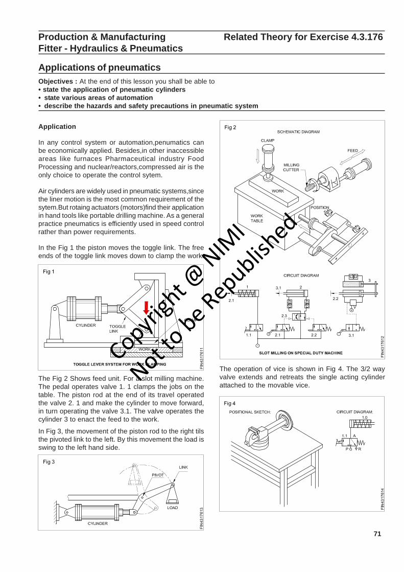
71
Production & Manufacturing Related Theory for Exercise 4.3.176Fitter - Hydraulics & Pneumatics
Applications of pneumaticsObjectives : At the end of this lesson you shall be able to• state the application of pneumatic cylinders• state various areas of automation• describe the hazards and safety precautions in pneumatic system
Application
In any control system or automation,penumatics canbe economically applied. Besides,in other inaccessibleareas like furnaces Pharmaceutical industry FoodProcessing and nuclear/reactors,compressed air is theonly choice to operate the control sytem.
Air cylinders are widely used in pneumatic systems,sincethe liner motion is the most common requirement of thesytem.But rotaing actuators (motors)find their applicationin hand tools like portable drilling machine. As a generalpractice pneumatics is efficiently used in speed controlrather than power requirements.
In the Fig 1 the piston moves the toggle link. The freeends of the toggle link moves down to clamp the work.
The Fig 2 Shows feed unit. For a slot milling machine.The pedal operates valve 1. 1 clamps the jobs on thetable. The piston rod at the end of its travel operatedthe valve 2. 1 and make the cylinder to move forward,in turn operating the valve 3.1. The valve operates thecylinder 3 to enact the feed to the work.
In Fig 3, the movement of the piston rod to the right tilsthe pivoted link to the left. By this movement the load isswing to the left hand side.
The operation of vice is shown in Fig 4. The 3/2 wayvalve extends and retreats the single acting cylinderattached to the movable vice.
Copyrigh
t @ NIM
I
Not to be Republish
ed
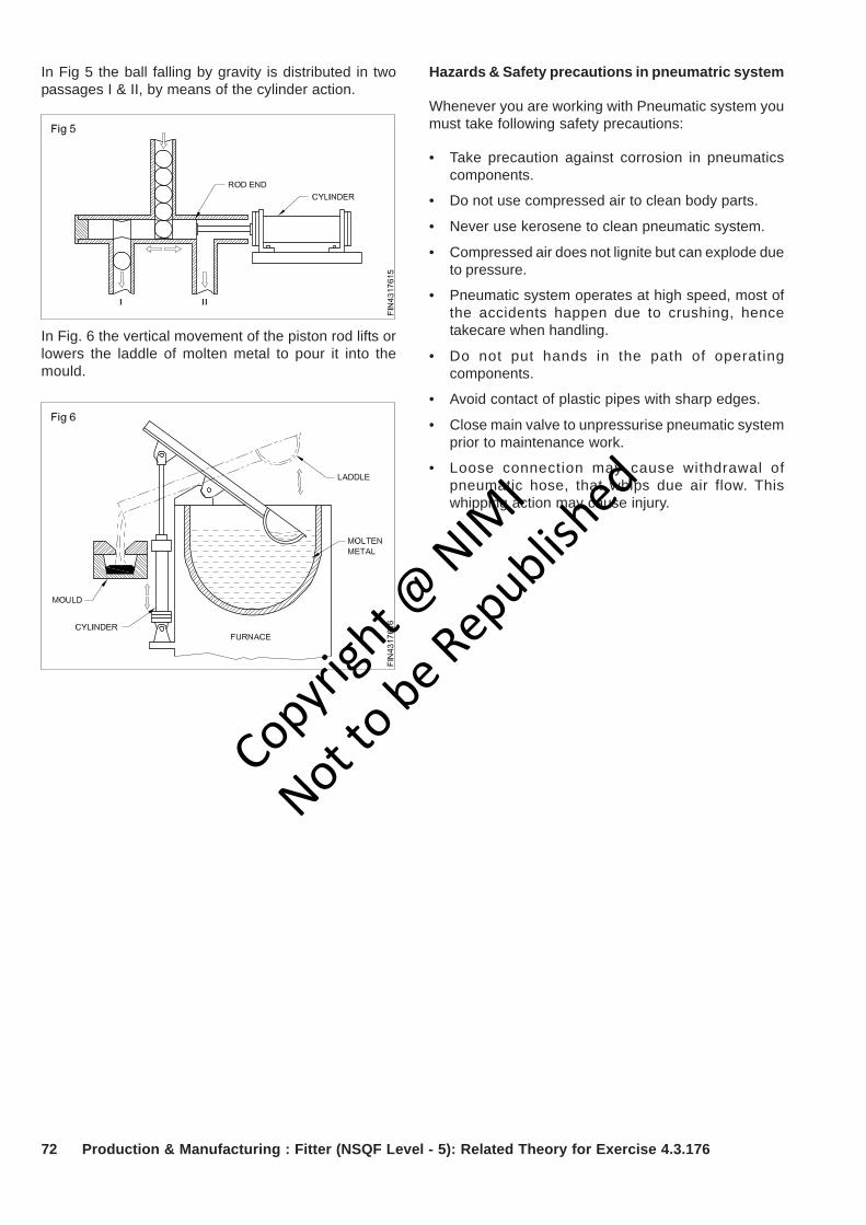
72 Production & Manufacturing : Fitter (NSQF Level - 5): Related Theory for Exercise 4.3.176
In Fig 5 the ball falling by gravity is distributed in twopassages I & II, by means of the cylinder action.
In Fig. 6 the vertical movement of the piston rod lifts orlowers the laddle of molten metal to pour it into themould.
Hazards & Safety precautions in pneumatric system
Whenever you are working with Pneumatic system youmust take following safety precautions:
• Take precaution against corrosion in pneumaticscomponents.
• Do not use compressed air to clean body parts.
• Never use kerosene to clean pneumatic system.
• Compressed air does not lignite but can explode dueto pressure.
• Pneumatic system operates at high speed, most ofthe accidents happen due to crushing, hencetakecare when handling.
• Do not put hands in the path of operatingcomponents.
• Avoid contact of plastic pipes with sharp edges.
• Close main valve to unpressurise pneumatic systemprior to maintenance work.
• Loose connection may cause withdrawal ofpneumatic hose, that whips due air flow. Thiswhipping action may cause injury.
Copyrigh
t @ NIM
I
Not to be Republish
ed
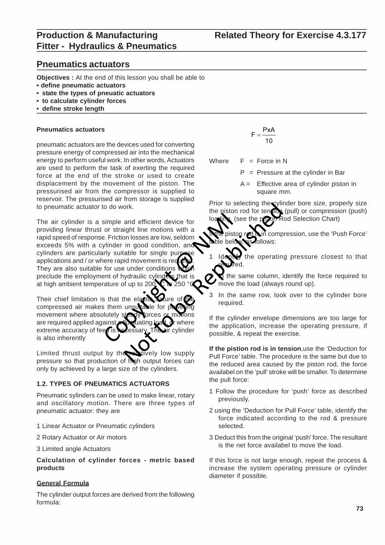
73
Production & Manufacturing Related Theory for Exercise 4.3.177Fitter - Hydraulics & Pneumatics
Pneumatics actuatorsObjectives : At the end of this lesson you shall be able to• define pneumatic actuators• state the types of pneuatic actuators• to calculate cylinder forces• define stroke length
Pneumatics actuators
pneumatic actuators are the devices used for convertingpressure energy of compressed air into the mechanicalenergy to perform useful work. In other words, Actuatorsare used to perform the task of exerting the requiredforce at the end of the stroke or used to createdisplacement by the movement of the piston. Thepressurised air from the compressor is supplied toreservoir. The pressurised air from storage is suppliedto pneumatic actuator to do work.
The air cylinder is a simple and efficient device forproviding linear thrust or straight line motions with arapid speed of response. Friction losses are low, seldomexceeds 5% with a cylinder in good condition, andcylinders are particularly suitable for single purposeapplications and / or where rapid movement is required.They are also suitable for use under conditions whichpreclude the employment of hydraulic cylinders that isat high ambient temperature of up to 200 °C to 250 °C
Their chief limitation is that the elastic nature of thecompressed air makes them unsuitable for poweringmovement where absolutely steady forces or motionsare required applied against a fluctuating load, or whereextreme accuracy of feed is necessary. The air cylinderis also inherently
Limited thrust output by the relatively low supplypressure so that production of high output forces canonly by achieved by a large size of the cylinders.
1.2. TYPES OF PNEUMATICS ACTUATORS
Pneumatic sylinders can be used to make linear, rotaryand oscillatory motion. There are three types ofpneumatic actuator: they are
1 Linear Actuator or Pneumatic cylinders
2 Rotary Actuator or Air motors
3 Limited angle Actuators
Calculation of cylinder forces - metric basedproducts
General Formula
The cylinder output forces are derived from the followingformula:
Where F = Force in N
P = Pressure at the cylinder in Bar
A = Effective area of cylinder piston insquare mm.
Prior to selecting the cylinder bore size, properly sizethe piston rod for tension (pull) or compression (push)loading. (see the piston Rod Selection Chart)
If the piston rod is in compression, use the ‘Push Force’table below, as follows:
1 Identify the operating pressure closest to thatrequired.
2 In the same column, identify the force required tomove the load (always round up).
3 In the same row, look over to the cylinder borerequired.
If the cylinder envelope dimensions are too large forthe application, increase the operating pressure, ifpossible, & repeat the exercise.
If the pistion rod is in tension,use the ‘Deduction forPull Force’ table. The procedure is the same but due tothe reduced area caused by the piston rod, the forceavailabel on the ‘pull’ stroke will be smaller. To determinethe pull force:
1 Follow the procedure for ‘push’ force as describedpreviously.
2 using the ‘Deduction for Pull Force’ table, identify theforce indicated according to the rod & pressureselected.
3 Deduct this from the original ‘push’ force. The resultantis the net force availabel to move the load.
If this force is not large enough, repeat the process &increase the system operating pressure or cylinderdiameter if possible.
10
PxAF =
Copyrigh
t @ NIM
I
Not to be Republish
ed
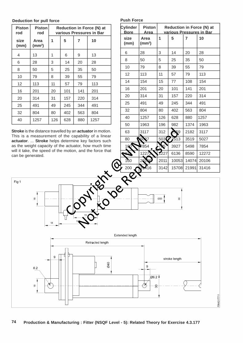
74 Production & Manufacturing : Fitter (NSQF Level - 5): Related Theory for Exercise 4.3.177
Deduction for pull force
Piston Piston Reduction in Force (N) atrod rod various Pressures in Bar
size Area 1 5 7 10(mm) (mm2)
4 13 1 6 9 13
6 28 3 14 20 28
8 50 5 25 35 50
10 79 8 39 55 79
12 113 11 57 79 113
16 201 20 101 141 201
20 314 31 157 220 314
25 491 49 245 344 491
32 804 80 402 563 804
40 1257 126 628 880 1257
Push Force
Cylinder Piston Reduction in Force (N) atBore Area various Pressures in Barsize Area 1 5 7 10(mm) (mm2)
6 28 3 14 20 28
8 50 5 25 35 50
10 79 8 39 55 79
12 113 11 57 79 113
14 154 15 77 108 154
16 201 20 101 141 201
20 314 31 157 220 314
25 491 49 245 344 491
32 804 80 402 563 804
40 1257 126 628 880 1257
50 1963 196 982 1374 1963
63 3117 312 1559 2182 3117
80 5027 503 2513 3519 5027
100 7854 785 3927 5498 7854
125 12272 1227 6136 8590 12272
160 20106 2011 10053 14074 20106
200 31416 3142 15708 21991 31416
Stroke is the distance travelled by an actuator in motion.This is a measurement of the capability of a linearactuator. ... Stroke helps determine key factors suchas the weight capacity of the actuator, how much timewill it take, the speed of the motion, and the force thatcan be generated.
Copyrigh
t @ NIM
I
Not to be Republish
ed
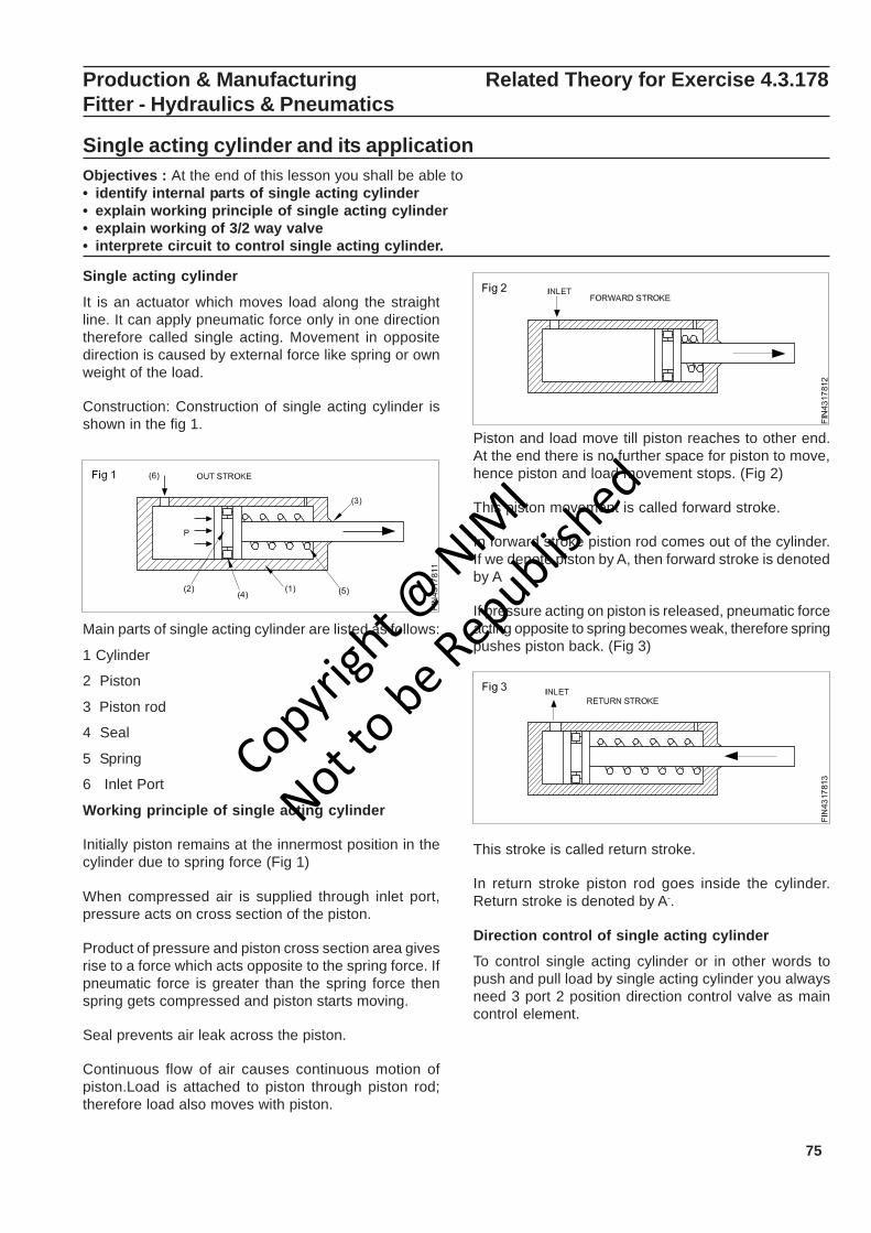
75
Production & Manufacturing Related Theory for Exercise 4.3.178Fitter - Hydraulics & Pneumatics
Single acting cylinder and its applicationObjectives : At the end of this lesson you shall be able to• identify internal parts of single acting cylinder• explain working principle of single acting cylinder• explain working of 3/2 way valve• interprete circuit to control single acting cylinder.
Single acting cylinder
It is an actuator which moves load along the straightline. It can apply pneumatic force only in one directiontherefore called single acting. Movement in oppositedirection is caused by external force like spring or ownweight of the load.
Construction: Construction of single acting cylinder isshown in the fig 1.
Main parts of single acting cylinder are listed as follows:
1 Cylinder
2 Piston
3 Piston rod
4 Seal
5 Spring
6 Inlet Port
Working principle of single acting cylinder
Initially piston remains at the innermost position in thecylinder due to spring force (Fig 1)
When compressed air is supplied through inlet port,pressure acts on cross section of the piston.
Product of pressure and piston cross section area givesrise to a force which acts opposite to the spring force. Ifpneumatic force is greater than the spring force thenspring gets compressed and piston starts moving.
Seal prevents air leak across the piston.
Continuous flow of air causes continuous motion ofpiston.Load is attached to piston through piston rod;therefore load also moves with piston.
Piston and load move till piston reaches to other end.At the end there is no further space for piston to move,hence piston and load movement stops. (Fig 2)
This piston movement is called forward stroke.
In forward stroke pistion rod comes out of the cylinder.If we denote piston by A, then forward stroke is denotedby A
If pressure acting on piston is released, pneumatic forceacting opposite to spring becomes weak, therefore springpushes piston back. (Fig 3)
This stroke is called return stroke.
In return stroke piston rod goes inside the cylinder.Return stroke is denoted by A-.
Direction control of single acting cylinder
To control single acting cylinder or in other words topush and pull load by single acting cylinder you alwaysneed 3 port 2 position direction control valve as maincontrol element.
Copyrigh
t @ NIM
I
Not to be Republish
ed
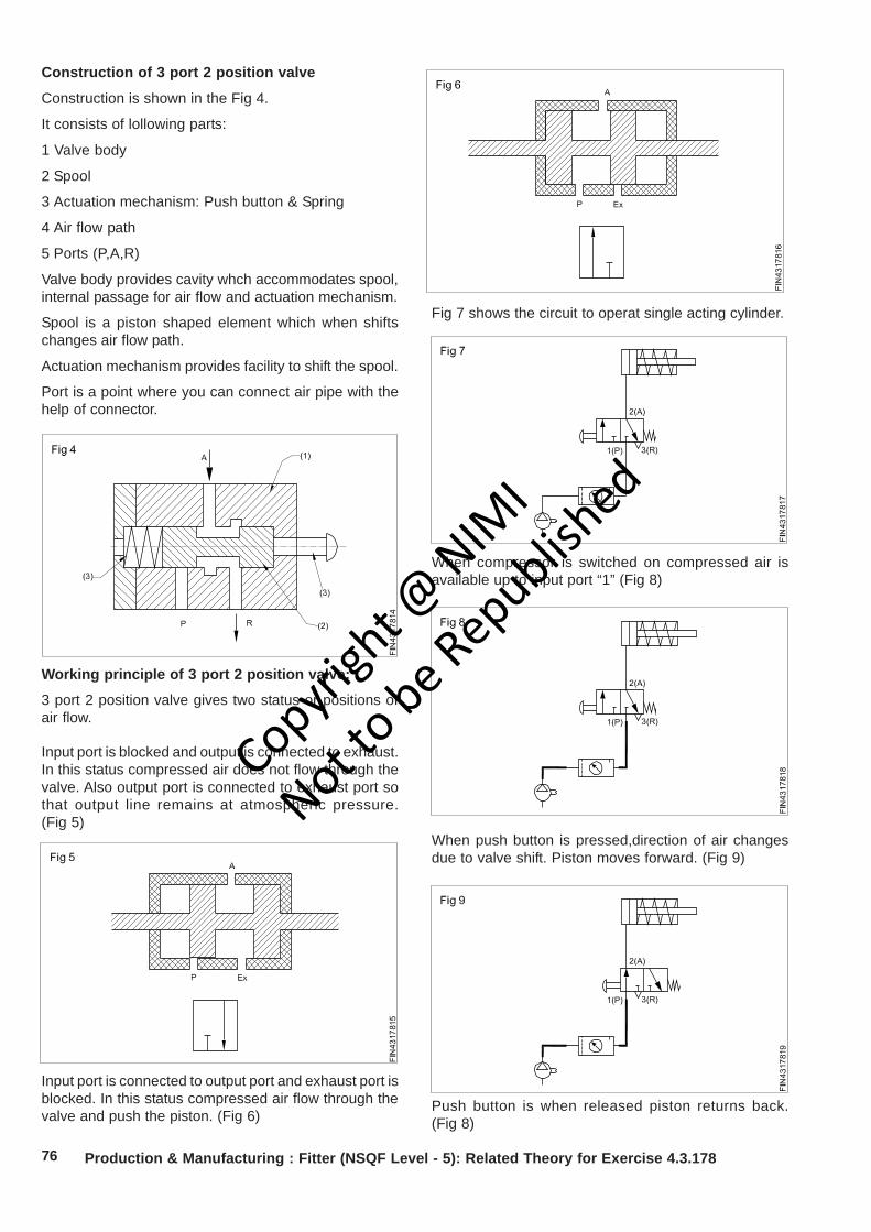
76
When push button is pressed,direction of air changesdue to valve shift. Piston moves forward. (Fig 9)
Production & Manufacturing : Fitter (NSQF Level - 5): Related Theory for Exercise 4.3.178
Fig 7 shows the circuit to operat single acting cylinder.
When compressor is switched on compressed air isavailable up to input port “1” (Fig 8)
Push button is when released piston returns back.(Fig 8)
Construction of 3 port 2 position valve
Construction is shown in the Fig 4.
It consists of lollowing parts:
1 Valve body
2 Spool
3 Actuation mechanism: Push button & Spring
4 Air flow path
5 Ports (P,A,R)
Valve body provides cavity whch accommodates spool,internal passage for air flow and actuation mechanism.
Spool is a piston shaped element which when shiftschanges air flow path.
Actuation mechanism provides facility to shift the spool.
Port is a point where you can connect air pipe with thehelp of connector.
Working principle of 3 port 2 position valve:
3 port 2 position valve gives two status or positions ofair flow.
Input port is blocked and output is connected to exhaust.In this status compressed air does not flow through thevalve. Also output port is connected to exhaust port sothat output line remains at atmospheric pressure.(Fig 5)
Input port is connected to output port and exhaust port isblocked. In this status compressed air flow through thevalve and push the piston. (Fig 6)
Copyrigh
t @ NIM
I
Not to be Republish
ed

77
Double acting cylinder and its applicationObjectives: At the end of this lesson you shall be able to• explain working principle of Double Acting Cylinder• explain operation of 5/2 way valve• use 5/2 way valve to operate double acting cylinder.
Double acting cylinder is an actuator which can push andpull the load using compressed air. It has two ports for airsypply. Fig 1 shows the construction of double actingcylinder.
Input Ports: For air supply
• Piston: Element which moves to and fro inside thecylinder.
• Cylinder: It confines air for the piston movement.
• Piston rod: A rod which connects piston and a load.
• Piston Seal: Seal which prevent leakage across thepiston.
• Rod Seal: Seal which prevents air leakage fromcylinder to the atmosphere.
• Piston End: Part of the cylinder consisting air passageand connected to the piston side.
• Rod End: Part of the cylinder consisting air passageand connected to the piston side.
When air is supplied through port A, force isexerted on the piston so that it moves in forwarddirection. This movement is called forward stroke.During forward stroke air already present at therod side exhausts through port B. (Fig 2)
Piston movement will stop if air does not exhaust.
When air is supplied through port B, air already presentexhausts through port A and piston retracts. (Fig 3)
Symbol of double acting cylinder is shown in fig 4
5 port 2 position valve
To operate double acting cylinder it is needed to changethe direction of air between ports A & B. Therefore avalve is required whcih has two output ports. 5 port 2position valve has two output ports. Construction isshown in fig 5.
• Valve body: It provide cavity to move spool andports.
• Spool: It is an element which change flow path whenmoves inside the valve body.
• Input port: Connection point where air enters intovalve. It is denoted by ‘P’ or number ‘1’.
Production & Manufacturing : Fitter (NSQF Level - 5): Related Theory for Exercise 4.3.178
Copyrigh
t @ NIM
I
Not to be Republish
ed
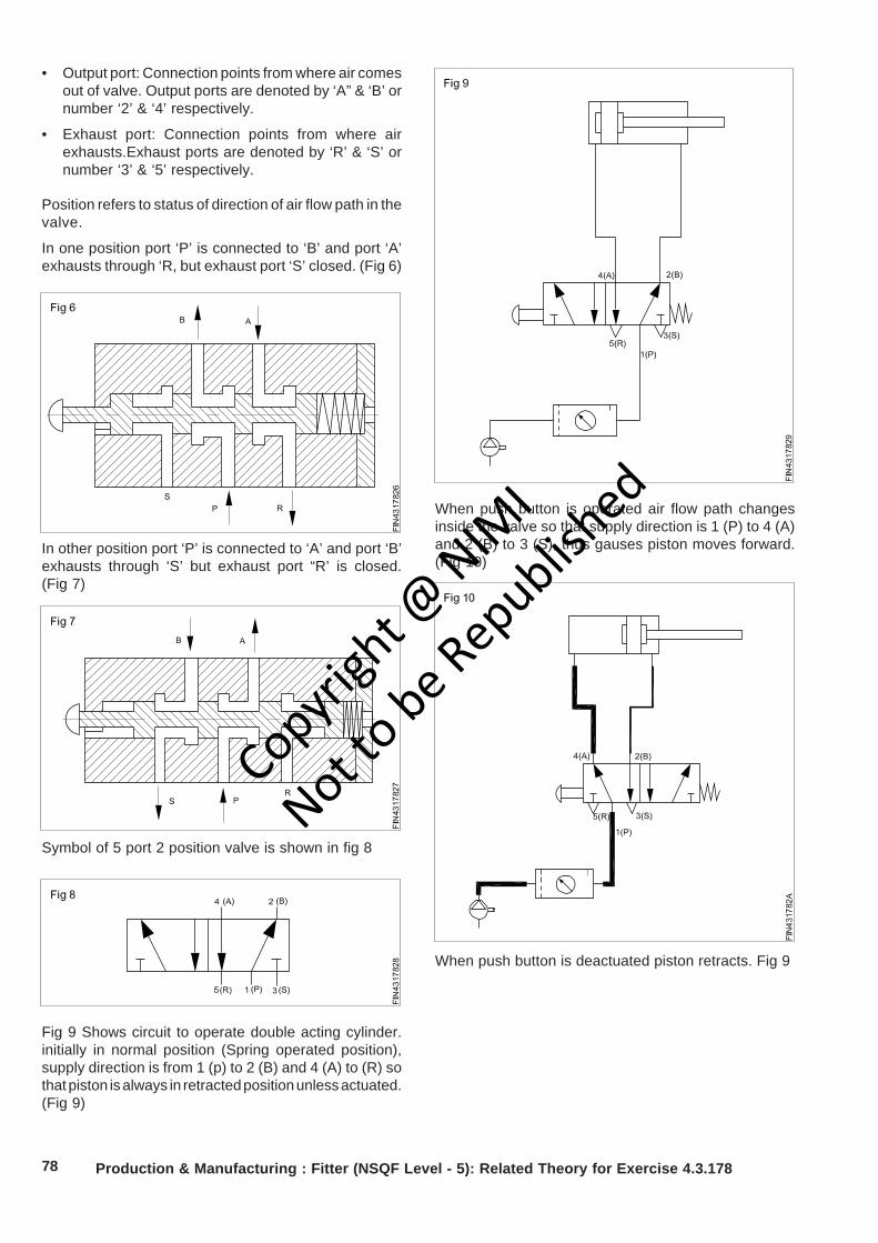
78
• Output port: Connection points from where air comesout of valve. Output ports are denoted by ‘A” & ‘B’ ornumber ‘2’ & ‘4’ respectively.
• Exhaust port: Connection points from where airexhausts.Exhaust ports are denoted by ‘R’ & ‘S’ ornumber ‘3’ & ‘5’ respectively.
Position refers to status of direction of air flow path in thevalve.
In one position port ‘P’ is connected to ‘B’ and port ‘A’exhausts through ‘R, but exhaust port ‘S’ closed. (Fig 6)
In other position port ‘P’ is connected to ‘A’ and port ‘B’exhausts through ‘S’ but exhaust port “R’ is closed.(Fig 7)
Symbol of 5 port 2 position valve is shown in fig 8
Fig 9 Shows circuit to operate double acting cylinder.initially in normal position (Spring operated position),supply direction is from 1 (p) to 2 (B) and 4 (A) to (R) sothat piston is always in retracted position unless actuated.(Fig 9)
When push button is operated air flow path changesinside the valve so that supply direction is 1 (P) to 4 (A)and 2 (B) to 3 (S), thus gauses piston moves forward.(Fig 10)
When push button is deactuated piston retracts. Fig 9
Production & Manufacturing : Fitter (NSQF Level - 5): Related Theory for Exercise 4.3.178
Copyrigh
t @ NIM
I
Not to be Republish
ed
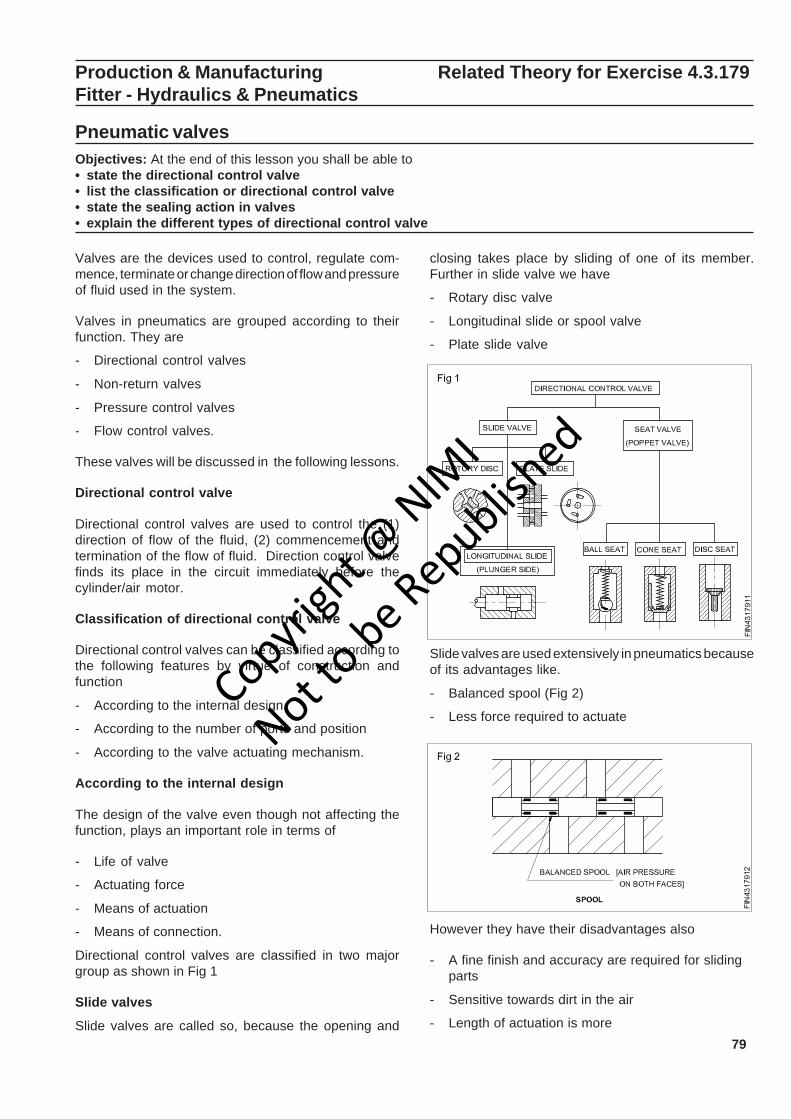
79
Production & Manufacturing Related Theory for Exercise 4.3.179Fitter - Hydraulics & Pneumatics
Pneumatic valvesObjectives: At the end of this lesson you shall be able to• state the directional control valve• list the classification or directional control valve• state the sealing action in valves• explain the different types of directional control valve
Valves are the devices used to control, regulate com-mence, terminate or change direction of flow and pressureof fluid used in the system.
Valves in pneumatics are grouped according to theirfunction. They are
- Directional control valves
- Non-return valves
- Pressure control valves
- Flow control valves.
These valves will be discussed in the following lessons.
Directional control valve
Directional control valves are used to control the (1)direction of flow of the fluid, (2) commencement andtermination of the flow of fluid. Direction control valvefinds its place in the circuit immediately before thecylinder/air motor.
Classification of directional control valve
Directional control valves can be classified according tothe following features by virtue of construction andfunction
- According to the internal design
- According to the number of ports and position
- According to the valve actuating mechanism.
According to the internal design
The design of the valve even though not affecting thefunction, plays an important role in terms of
- Life of valve
- Actuating force
- Means of actuation
- Means of connection.
Directional control valves are classified in two majorgroup as shown in Fig 1
Slide valves
Slide valves are called so, because the opening and
Slide valves are used extensively in pneumatics becauseof its advantages like.
- Balanced spool (Fig 2)
- Less force required to actuate
However they have their disadvantages also
- A fine finish and accuracy are required for slidingparts
- Sensitive towards dirt in the air
- Length of actuation is more
closing takes place by sliding of one of its member.Further in slide valve we have
- Rotary disc valve
- Longitudinal slide or spool valve
- Plate slide valve
Copyrigh
t @ NIM
I
Not to be Republish
ed
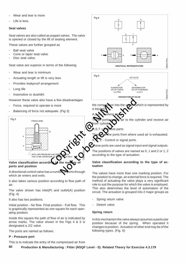
80
- Wear and tear is more
- Life is less.
Seat valves
Seat valves are also called as poppet valves. The valveis opened or closed by the lift of seating element.
These valves are further grouped as
- Ball seat valve- Cone or taper seat valve- Disc seat valve.
Seat valve are superior in terms of the following
- Wear and tear is minimum
- Actuating length or lift is very less
- Provides leakproof arrangement
- Long life
- Insensitive to dust/dirt
However these valve also have a few disadvantages
- Force, required to operate is more
- Balancing of force not adequate. (Fig 3)
Valve classification according to the number ofports and position
A directional control valve has a number of ports throughwhich air enters and exits.
It also takes various position according to flow path ofair.
The valve shown has inlet(P) and outlet(A) position(Fig. 4)
It also has two positions.
Initial position - No flow. Final position - Full flow. Thisis graphically represented as one square for each oper-ating position.
Inside this square the path of flow of air is indicated byarrow marks. The valve shown in the Figs 4 & 5 isdesignated a 2/2 valve.
The ports are named as follows:
P - Pressure port
This is to indicate the entry of the compressed air fromProduction & Manufacturing : Fitter (NSQF Level - 5): Related Theory for Exercise 4.3.179
the compressor into the valve. (which is represented bya square)
A,B,C - working parts
These ports supply air to the cylinder and receive airfrom cylinder.
R,S,T = Exhaust parts
These are the ports from where used air is exhausted.
X, Y, Z - Control or signal ports.
These ports are used as signal input and signal outputs.
The positions of valves are named as 0, 1 and 2 or 1, 2according to the type of actuation.
Valve classification according to the type of ac-tuation
The valves have more than one marking position. Forthe position to change, an external force is required. Themethod of actuating the valve plays a very significantrole to suit the purpose for which the valve is employed.This also determines the level of automation of thecircuit. The actuation is grouped into 2 major groups as
- Spring return valve
- Detent valve
Spring return
In this mechanism the valve always assumes a particularposition because of the spring. When operated itchanges ts position. Actuation of other end may be of thefollowing types. (Fig. 6)
Copyrigh
t @ NIM
I
Not to be Republish
ed
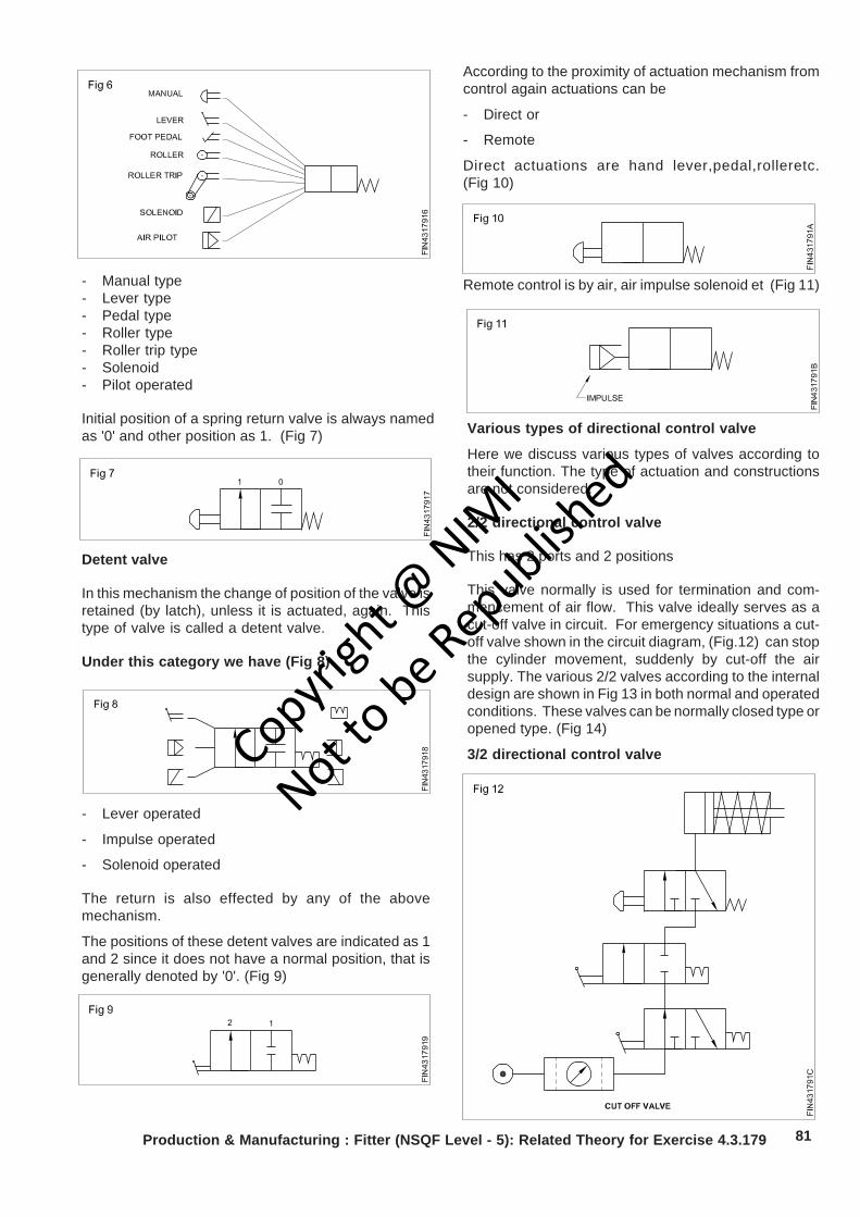
81Production & Manufacturing : Fitter (NSQF Level - 5): Related Theory for Exercise 4.3.179
- Manual type- Lever type- Pedal type- Roller type- Roller trip type- Solenoid- Pilot operated
Initial position of a spring return valve is always namedas '0' and other position as 1. (Fig 7)
Detent valve
In this mechanism the change of position of the valve isretained (by latch), unless it is actuated, again. Thistype of valve is called a detent valve.
Under this category we have (Fig 8)
- Lever operated
- Impulse operated
- Solenoid operated
The return is also effected by any of the abovemechanism.
The positions of these detent valves are indicated as 1and 2 since it does not have a normal position, that isgenerally denoted by '0'. (Fig 9)
According to the proximity of actuation mechanism fromcontrol again actuations can be
- Direct or
- Remote
Direct actuations are hand lever,pedal,rolleretc.(Fig 10)
Remote control is by air, air impulse solenoid et (Fig 11)
Various types of directional control valve
Here we discuss various types of valves according totheir function. The type of actuation and constructionsare not considered.
2/2 directional control valve
This has 2 ports and 2 positions
This valve normally is used for termination and com-mencement of air flow. This valve ideally serves as acut-off valve in circuit. For emergency situations a cut-off valve shown in the circuit diagram, (Fig.12) can stopthe cylinder movement, suddenly by cut-off the airsupply. The various 2/2 valves according to the internaldesign are shown in Fig 13 in both normal and operatedconditions. These valves can be normally closed type oropened type. (Fig 14)
3/2 directional control valveCopyrigh
t @ NIM
I
Not to be Republish
ed

82 Production & Manufacturing : Fitter (NSQF Level - 5): Related Theory for Exercise 4.3.179
The main advantage of the 3/2 valve is that it gives ventfor the used air through the exhaust port. It has 3 portsP, A and R. This facilitates to generate a signal and alsoto cancel the signal in the valve as shown in the Fig 15initial position P is blocked, A is connected to R. In theactuated position P gets connected to A, R gets blocked.
A 3/2 valve is ideally suited for an application of inletvalve, and also for actuating a single acting cylinder(Fig 15).
This valve is also very ideal for remote control of maindirection control valves as impulse and pilot type. Theconstruction of various 3/2 valves in normal and actuatedconditions are shown in Fig 15.
3/2 valves are available as both normally opened type orclosed type, which can be selected according to therequirement of the circuit. (Fig 16)
4/2 directional valve
The main application of a 4/2 valve is in actuation of adouble acting cylinder. This valve has 4 ports namely
P - Pressure port
A & B - Working port
R - Exhaust port
In normal position (Fig 17) P is connected to A and B isconnected to R and vice-versa in the other position.
The application of a 4/2 valve to actuate of double actingcylinder is shown in Fig 18.
Copyrigh
t @ NIM
I
Not to be Republish
ed
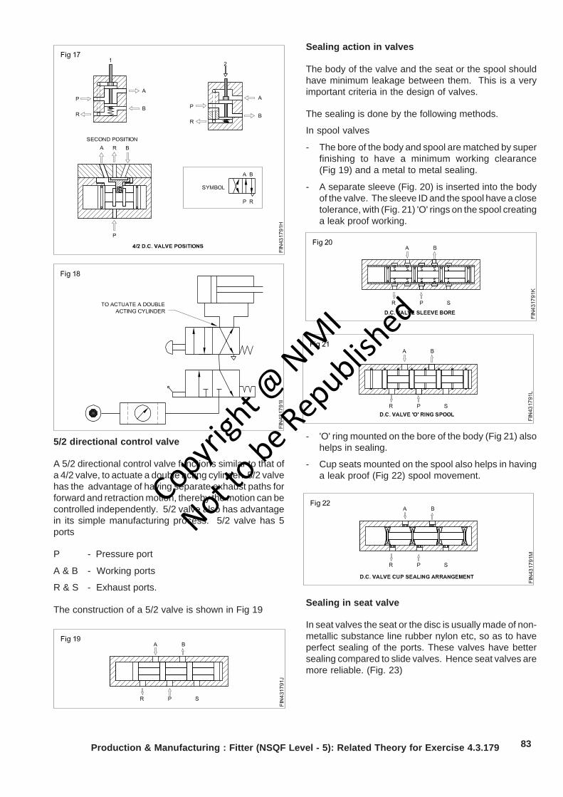
83Production & Manufacturing : Fitter (NSQF Level - 5): Related Theory for Exercise 4.3.179
5/2 directional control valve
A 5/2 directional control valve functions similar to that ofa 4/2 valve, to actuate a double acting cylinder. 5/2 valvehas the advantage of having separate exhaust paths forforward and retraction motion, thereby the motion can becontrolled independently. 5/2 valve also has advantagein its simple manufacturing process. 5/2 valve has 5ports
P - Pressure port
A & B - Working ports
R & S - Exhaust ports.
The construction of a 5/2 valve is shown in Fig 19
Sealing action in valves
The body of the valve and the seat or the spool shouldhave minimum leakage between them. This is a veryimportant criteria in the design of valves.
The sealing is done by the following methods.
In spool valves
- The bore of the body and spool are matched by superfinishing to have a minimum working clearance(Fig 19) and a metal to metal sealing.
- A separate sleeve (Fig. 20) is inserted into the bodyof the valve. The sleeve ID and the spool have a closetolerance, with (Fig. 21) 'O' rings on the spool creatinga leak proof working.
- 'O' ring mounted on the bore of the body (Fig 21) alsohelps in sealing.
- Cup seats mounted on the spool also helps in havinga leak proof (Fig 22) spool movement.
Sealing in seat valve
In seat valves the seat or the disc is usually made of non-metallic substance line rubber nylon etc, so as to haveperfect sealing of the ports. These valves have bettersealing compared to slide valves. Hence seat valves aremore reliable. (Fig. 23)
Copyrigh
t @ NIM
I
Not to be Republish
ed
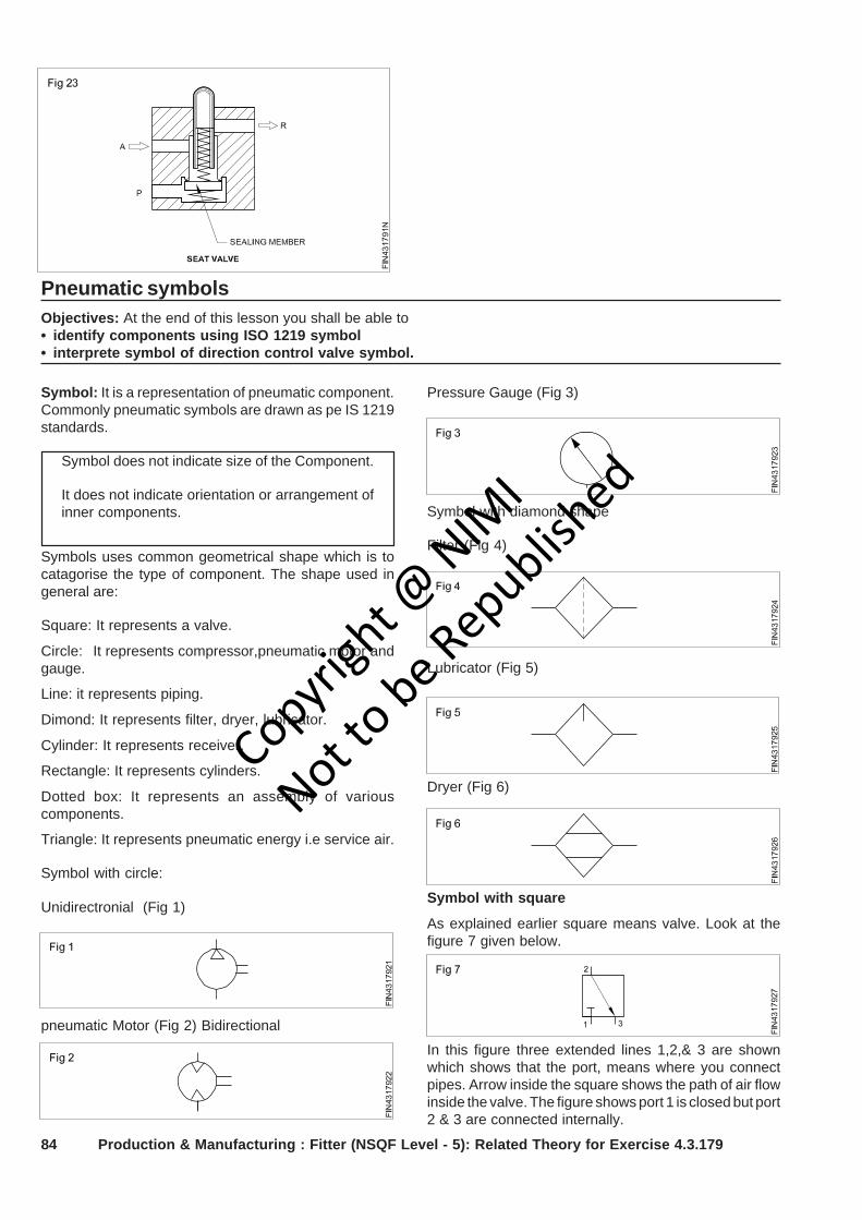
84
Symbol with square
As explained earlier square means valve. Look at thefigure 7 given below.
Pneumatic symbolsObjectives: At the end of this lesson you shall be able to• identify components using ISO 1219 symbol• interprete symbol of direction control valve symbol.
Symbol: It is a representation of pneumatic component.Commonly pneumatic symbols are drawn as pe IS 1219standards.
Symbol does not indicate size of the Component.
It does not indicate orientation or arrangement ofinner components.
Symbols uses common geometrical shape which is tocatagorise the type of component. The shape used ingeneral are:
Square: It represents a valve.
Circle: It represents compressor,pneumatic motor andgauge.
Line: it represents piping.
Dimond: It represents filter, dryer, lubricator.
Cylinder: It represents receiver.
Rectangle: It represents cylinders.
Dotted box: It represents an assembly of variouscomponents.
Triangle: It represents pneumatic energy i.e service air.
Symbol with circle:
Unidirectronial (Fig 1)
pneumatic Motor (Fig 2) Bidirectional
Pressure Gauge (Fig 3)
Symbol with diamond shape
Filter (Fig 4)
Lubricator (Fig 5)
Dryer (Fig 6)
In this figure three extended lines 1,2,& 3 are shownwhich shows that the port, means where you connectpipes. Arrow inside the square shows the path of air flowinside the valve. The figure shows port 1 is closed but port2 & 3 are connected internally.
Production & Manufacturing : Fitter (NSQF Level - 5): Related Theory for Exercise 4.3.179
Copyrigh
t @ NIM
I
Not to be Republish
ed
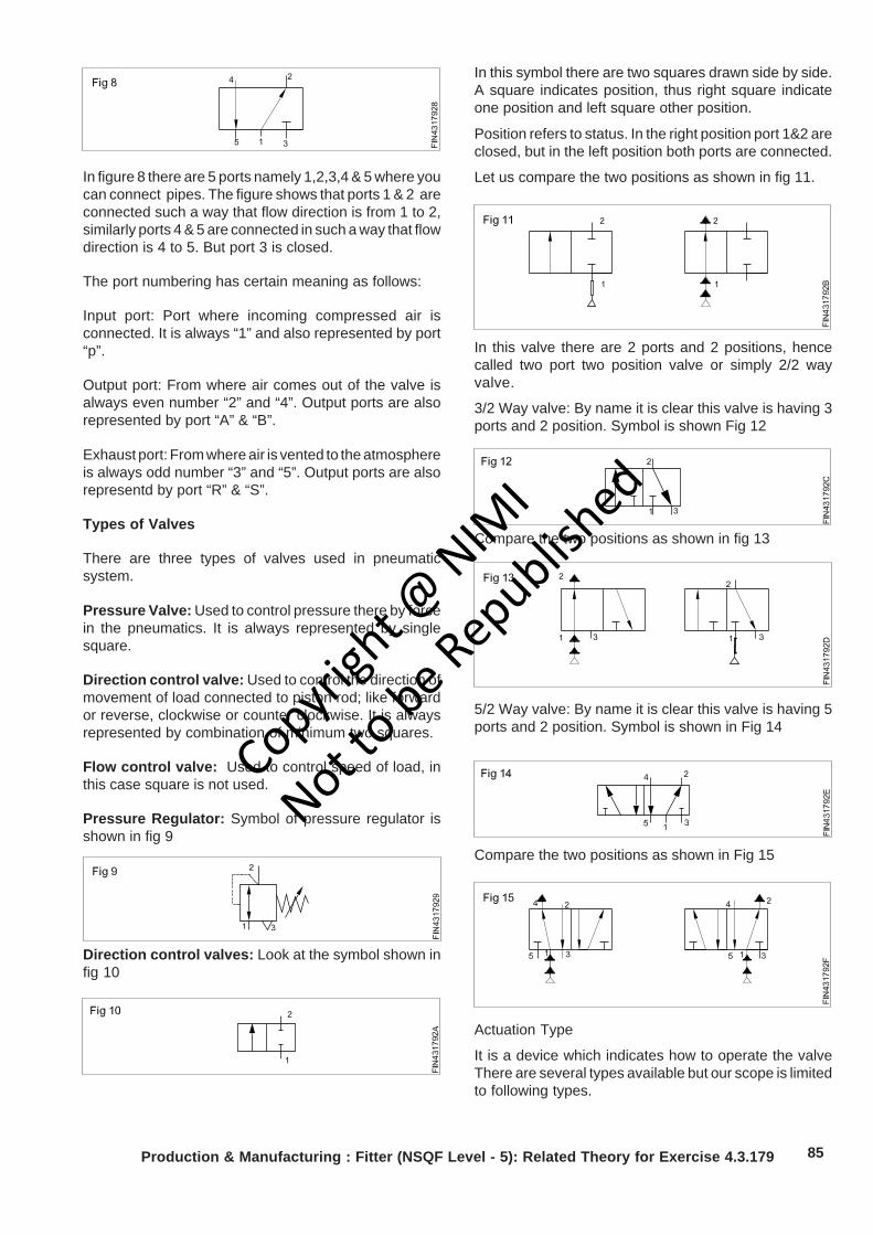
85Production & Manufacturing : Fitter (NSQF Level - 5): Related Theory for Exercise 4.3.179
In figure 8 there are 5 ports namely 1,2,3,4 & 5 where youcan connect pipes. The figure shows that ports 1 & 2 areconnected such a way that flow direction is from 1 to 2,similarly ports 4 & 5 are connected in such a way that flowdirection is 4 to 5. But port 3 is closed.
The port numbering has certain meaning as follows:
Input port: Port where incoming compressed air isconnected. It is always “1” and also represented by port“p”.
Output port: From where air comes out of the valve isalways even number “2” and “4”. Output ports are alsorepresented by port “A” & “B”.
Exhaust port: From where air is vented to the atmosphereis always odd number “3” and “5”. Output ports are alsorepresentd by port “R” & “S”.
Types of Valves
There are three types of valves used in pneumaticsystem.
Pressure Valve: Used to control pressure there by forcein the pneumatics. It is always represented by singlesquare.
Direction control valve: Used to control the direction ofmovement of load connected to piston rod; like forwardor reverse, clockwise or counter clockwise. It is alwaysrepresented by combination of minimum two squares.
Flow control valve: Used to control speed of load, inthis case square is not used.
Pressure Regulator: Symbol of pressure regulator isshown in fig 9
In this symbol there are two squares drawn side by side.A square indicates position, thus right square indicateone position and left square other position.
Position refers to status. In the right position port 1&2 areclosed, but in the left position both ports are connected.
Let us compare the two positions as shown in fig 11.
In this valve there are 2 ports and 2 positions, hencecalled two port two position valve or simply 2/2 wayvalve.
3/2 Way valve: By name it is clear this valve is having 3ports and 2 position. Symbol is shown Fig 12
Compare the two positions as shown in fig 13
Compare the two positions as shown in Fig 15
Actuation Type
It is a device which indicates how to operate the valveThere are several types available but our scope is limitedto following types.
Direction control valves: Look at the symbol shown infig 10
5/2 Way valve: By name it is clear this valve is having 5ports and 2 position. Symbol is shown in Fig 14
Copyrigh
t @ NIM
I
Not to be Republish
ed
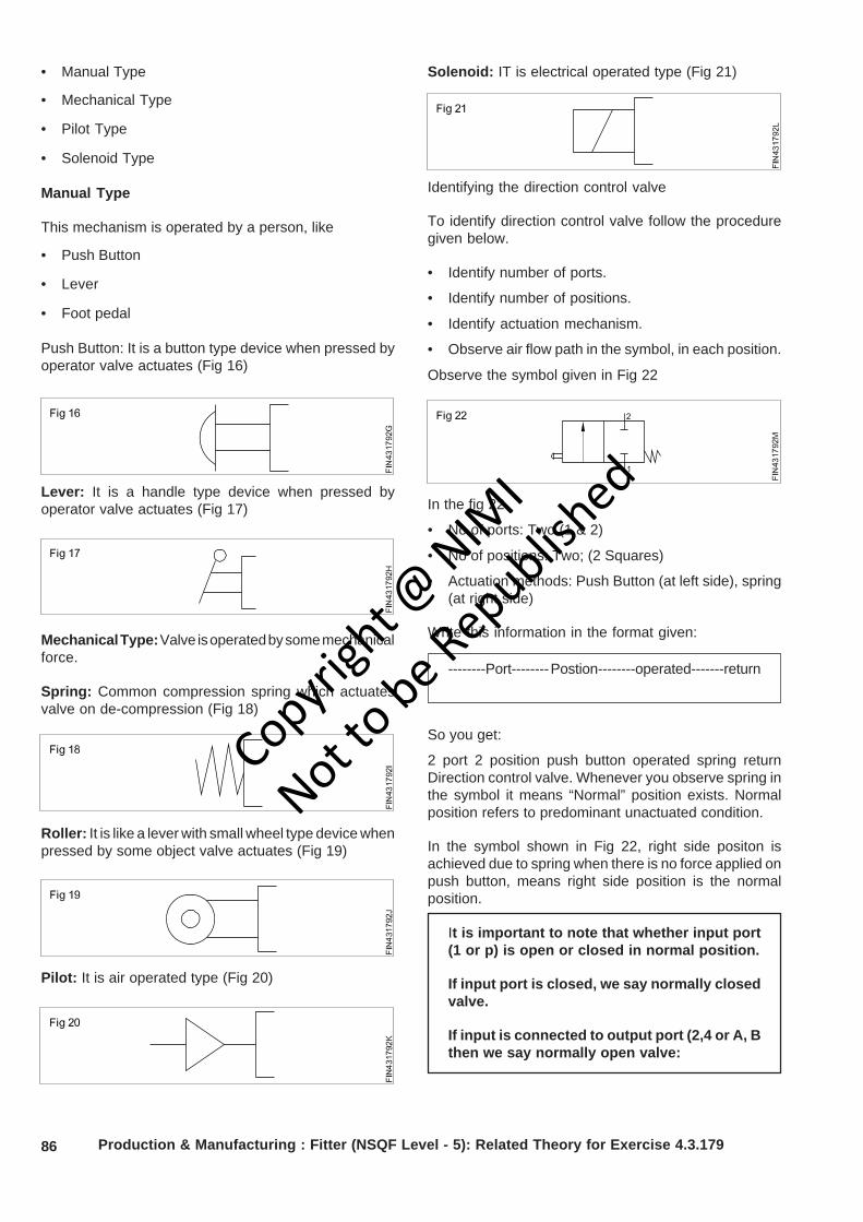
86 Production & Manufacturing : Fitter (NSQF Level - 5): Related Theory for Exercise 4.3.179
• Manual Type
• Mechanical Type
• Pilot Type
• Solenoid Type
Manual Type
This mechanism is operated by a person, like
• Push Button
• Lever
• Foot pedal
Push Button: It is a button type device when pressed byoperator valve actuates (Fig 16)
Lever: It is a handle type device when pressed byoperator valve actuates (Fig 17)
Mechanical Type: Valve is operated by some mechanicalforce.
Spring: Common compression spring which actuatesvalve on de-compression (Fig 18)
Roller: It is like a lever with small wheel type device whenpressed by some object valve actuates (Fig 19)
Pilot: It is air operated type (Fig 20)
Solenoid: IT is electrical operated type (Fig 21)
Identifying the direction control valve
To identify direction control valve follow the proceduregiven below.
• Identify number of ports.
• Identify number of positions.
• Identify actuation mechanism.
• Observe air flow path in the symbol, in each position.
Observe the symbol given in Fig 22
In the fig 22
• No of ports: Two (1 & 2)
• No of positions: Two; (2 Squares)
• Actuation methods: Push Button (at left side), spring(at right side)
Write this information in the format given:
So you get:
2 port 2 position push button operated spring returnDirection control valve. Whenever you observe spring inthe symbol it means “Normal” position exists. Normalposition refers to predominant unactuated condition.
In the symbol shown in Fig 22, right side positon isachieved due to spring when there is no force applied onpush button, means right side position is the normalposition.
It is important to note that whether input port(1 or p) is open or closed in normal position.
If input port is closed, we say normally closedvalve.
If input is connected to output port (2,4 or A, Bthen we say normally open valve:
--------Port-------- Postion--------operated-------return
Copyrigh
t @ NIM
I
Not to be Republish
ed

87
In the symbol shown above, in normal position input portis closed therefore valve is normally closed valve.
We can rewrite complete designation of the valve asfollows:
2 port 2 position push button operated spring returnnormally closed Direction Control Valve.
Lets try to identify valves given in the next pages. (Fig 23to Fig 59)
Symbol Designation
2 port 2 position push button operated spring returnnormally closed Direction Control Valve.
2 port 2 position lever operated spring return normallyclosed Direction Control Valve.
2 port 2 position lever operated spring return normallyopen Direction Control Valve.
2 port 2 position foot pedal operated spring return normallyclosed Direction Control Valve.
2 port 2 position foot pedal operated spring return normallyopen Direction Control Valve.
2 port 2 position roller operated spring return normallyclosed Direction Control Valve.
2 port 2 position roller operated spring return normallyopen Direction Control Valve.
2 port 2 position pilot operated spring return normallyclose Direction Control Valve.
Production & Manufacturing : Fitter (NSQF Level - 5): Related Theory for Exercise 4.3.179
Copyrigh
t @ NIM
I
Not to be Republish
ed
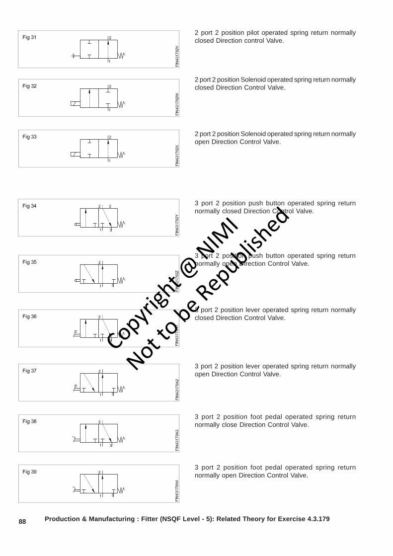
88 Production & Manufacturing : Fitter (NSQF Level - 5): Related Theory for Exercise 4.3.179
2 port 2 position pilot operated spring return normallyclosed Direction control Valve.
2 port 2 position Solenoid operated spring return normallyclosed Direction Control Valve.
2 port 2 position Solenoid operated spring return normallyopen Direction Control Valve.
3 port 2 position push button operated spring returnnormally closed Direction Control Valve.
3 port 2 position push button operated spring returnnormally open Direction Control Valve.
3 port 2 position lever operated spring return normallyclosed Direction Control Valve.
3 port 2 position lever operated spring return normallyopen Direction Control Valve.
3 port 2 position foot pedal operated spring returnnormally close Direction Control Valve.
3 port 2 position foot pedal operated spring returnnormally open Direction Control Valve.
Copyrigh
t @ NIM
I
Not to be Republish
ed
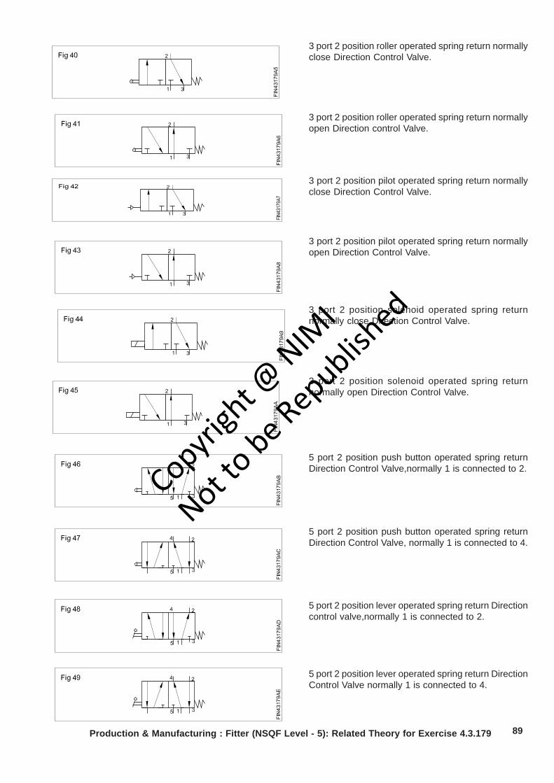
89Production & Manufacturing : Fitter (NSQF Level - 5): Related Theory for Exercise 4.3.179
3 port 2 position roller operated spring return normallyclose Direction Control Valve.
3 port 2 position roller operated spring return normallyopen Direction control Valve.
3 port 2 position pilot operated spring return normallyclose Direction Control Valve.
3 port 2 position pilot operated spring return normallyopen Direction Control Valve.
3 port 2 position solenoid operated spring returnnormally close Direction Control Valve.
3 port 2 position solenoid operated spring returnnormally open Direction Control Valve.
5 port 2 position push button operated spring returnDirection Control Valve,normally 1 is connected to 2.
5 port 2 position push button operated spring returnDirection Control Valve, normally 1 is connected to 4.
5 port 2 position lever operated spring return Directioncontrol valve,normally 1 is connected to 2.
5 port 2 position lever operated spring return DirectionControl Valve normally 1 is connected to 4.
Copyrigh
t @ NIM
I
Not to be Republish
ed
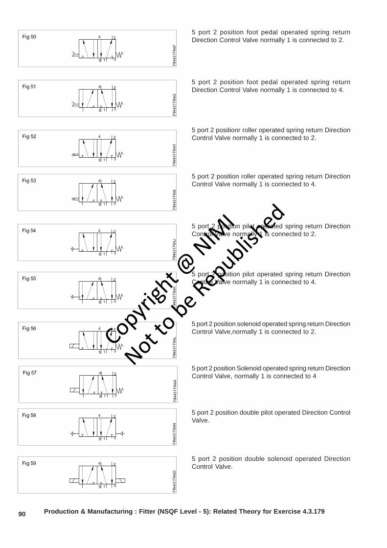
90 Production & Manufacturing : Fitter (NSQF Level - 5): Related Theory for Exercise 4.3.179
5 port 2 position foot pedal operated spring returnDirection Control Valve normally 1 is connected to 2.
5 port 2 position foot pedal operated spring returnDirection Control Valve normally 1 is connected to 4.
5 port 2 positionr roller operated spring return DirectionControl Valve normally 1 is connected to 2.
5 port 2 position roller operated spring return DirectionControl Valve normally 1 is connected to 4.
5 port 2 position pilot operated spring return DirectionControl Valve normally 1 is connected to 2.
5 port 2 position pilot operated spring return DirectionControl Valve normally 1 is connected to 4.
5 port 2 position solenoid operated spring return DirectionControl Valve,normally 1 is connected to 2.
5 port 2 position Solenoid operated spring return DirectionControl Valve, normally 1 is connected to 4
5 port 2 position double pilot operated Direction ControlValve.
5 port 2 position double solenoid operated DirectionControl Valve.
Copyrigh
t @ NIM
I
Not to be Republish
ed
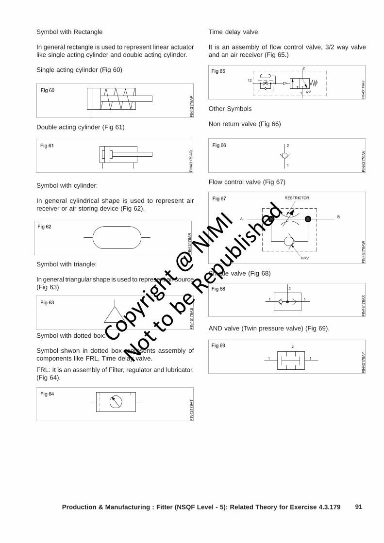
91
Symbol with Rectangle
In general rectangle is used to represent linear actuatorlike single acting cylinder and double acting cylinder.
Single acting cylinder (Fig 60)
Double acting cylinder (Fig 61)
Symbol with cylinder:
In general cylindrical shape is used to represent airreceiver or air storing device (Fig 62).
Time delay valve
It is an assembly of flow control valve, 3/2 way valveand an air receiver (Fig 65.)
Other Symbols
Non return valve (Fig 66)
Flow control valve (Fig 67)
Shuttle valve (Fig 68)Symbol with triangle:
In general triangular shape is used to represent air source(Fig 63).
Symbol with dotted box:
Symbol shwon in dotted box represents assembly ofcomponents like FRL, Time delay valve.
FRL: It is an assembly of Filter, regulator and lubricator.(Fig 64).
AND valve (Twin pressure valve) (Fig 69).
Production & Manufacturing : Fitter (NSQF Level - 5): Related Theory for Exercise 4.3.179
Copyrigh
t @ NIM
I
Not to be Republish
ed
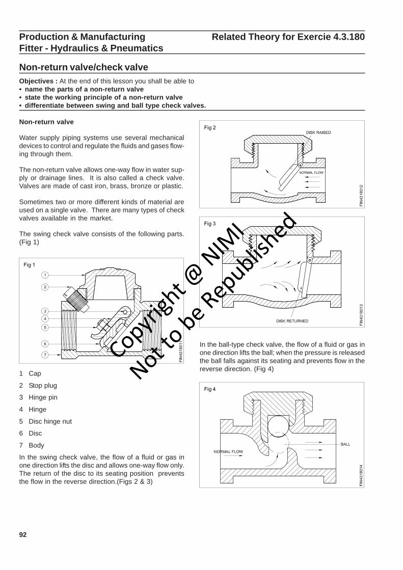
92
Production & Manufacturing Related Theory for Exercie 4.3.180Fitter - Hydraulics & Pneumatics
Non-return valve/check valveObjectives : At the end of this lesson you shall be able to• name the parts of a non-return valve• state the working principle of a non-return valve• differentiate between swing and ball type check valves.
Non-return valve
Water supply piping systems use several mechanicaldevices to control and regulate the fluids and gases flow-ing through them.
The non-return valve allows one-way flow in water sup-ply or drainage lines. It is also called a check valve.Valves are made of cast iron, brass, bronze or plastic.
Sometimes two or more different kinds of material areused on a single valve. There are many types of checkvalves available in the market.
The swing check valve consists of the following parts.(Fig 1)
1 Cap
2 Stop plug
3 Hinge pin
4 Hinge
5 Disc hinge nut
6 Disc
7 Body
In the swing check valve, the flow of a fluid or gas inone direction lifts the disc and allows one-way flow only.The return of the disc to its seating position preventsthe flow in the reverse direction.(Figs 2 & 3)
In the ball-type check valve, the flow of a fluid or gas inone direction lifts the ball; when the pressure is releasedthe ball falls against its seating and prevents flow in thereverse direction. (Fig 4)
Copyrigh
t @ NIM
I
Not to be Republish
ed
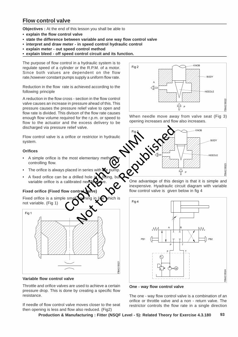
93
Flow control valveObjectives : At the end of this lesson you shall be able to• explain the flow control valve• state the difference between variable and one way flow control valve• interpret and draw meter - in speed control hydraulic control• explain meter - out speed control method• explain bleed - off speed control circuit and its function.
The purpose of flow control in a hydraulic system is toregulate speed of a cylinder or the R.P.M. of a motor.Since both values are dependent on the flowrate,however constant pumps supply a uniform flow rate.
Reduction in the flow rate is achieved according to thefollowing principle
A reduction in the flow cross - section in the flow controlvalve causes an increase in pressure ahead of this. Thispressure causes the pressure relief valve to open andflow rate is divided. This divison of the flow rate causesenough flow volume required for the r.p.m. or speed toflow to the actuator and the excess delivery to bedischarged via pressure relief valve.
Flow control valve is a orifice or restrictor in hydraulicsystem.
Orifices
• A simple orifice is the most elementary method forcontrolling flow.
• The orifice is always placed in series with the pump.
• A fixed orifice can be a drilled hole in a fitting, butvariable orifice is a calibrated needle valve.
Fixed orifice (Fixed flow control valve)
Fixed orifice is a simple small opening in line which isnot variable. (Fig 1)
When needle move away from valve seat (Fig 3)opening increases and flow also increases.
Variable flow control valve
Throttle and orifice valves are used to achieve a certainpressure drop. This is done by creating a specific flowresistance.
If needle of flow control valve moves closer to the seatthen opening is less and flow also reduced. (Fig2)
Production & Manufacturing : Fitter (NSQF Level - 5): Related Theory for Exercise 4.3.180
One advantage of this design is that it is simple andinexpensive. Hyadraulic circuit diagram with variableflow control valve is given below in fig 4
One - way flow control valve
The one - way flow control valve is a combination of anorifice or throttle valve and a non - return valve. Therestrictor controls the flow rate in a single direction
Copyrigh
t @ NIM
I
Not to be Republish
ed
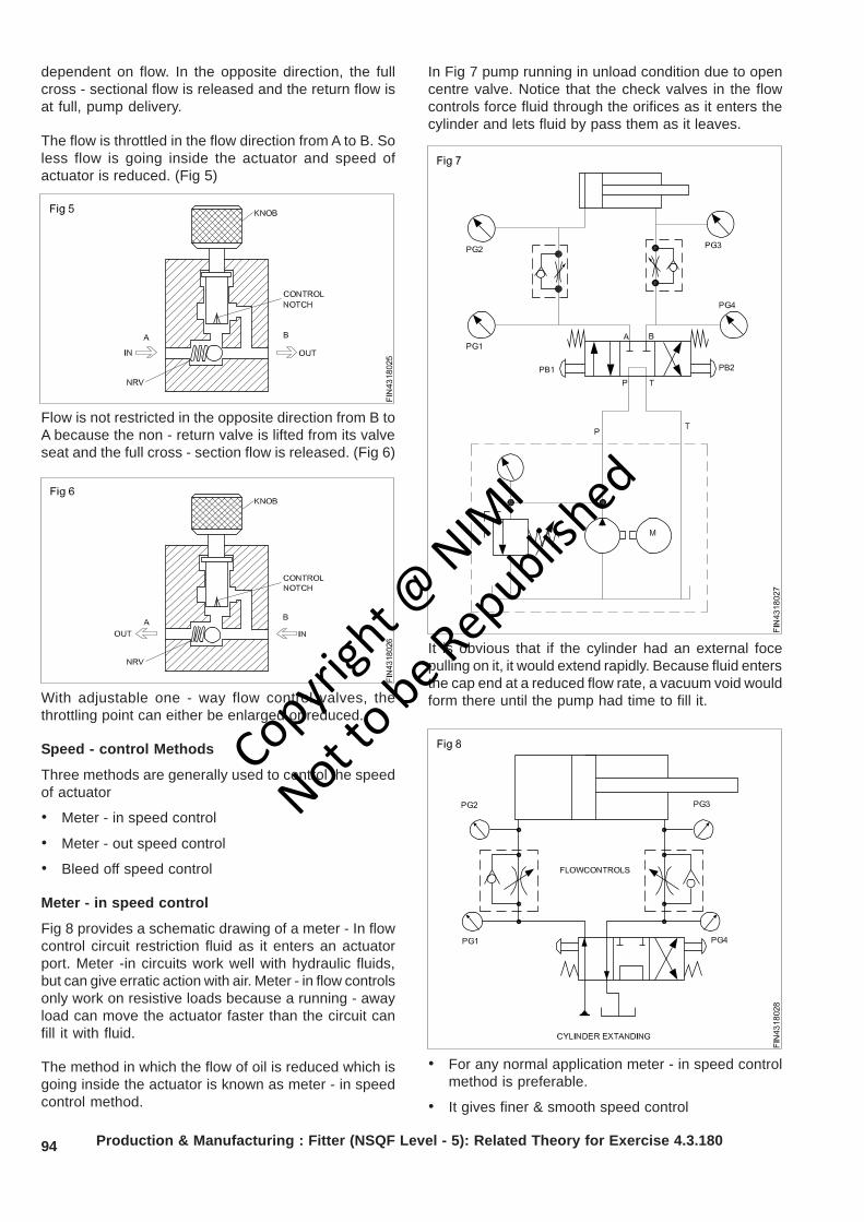
94
dependent on flow. In the opposite direction, the fullcross - sectional flow is released and the return flow isat full, pump delivery.
The flow is throttled in the flow direction from A to B. Soless flow is going inside the actuator and speed ofactuator is reduced. (Fig 5)
In Fig 7 pump running in unload condition due to opencentre valve. Notice that the check valves in the flowcontrols force fluid through the orifices as it enters thecylinder and lets fluid by pass them as it leaves.
With adjustable one - way flow control valves, thethrottling point can either be enlarged or reduced.
Speed - control Methods
Three methods are generally used to control the speedof actuator
• Meter - in speed control
• Meter - out speed control
• Bleed off speed control
Meter - in speed control
Fig 8 provides a schematic drawing of a meter - In flowcontrol circuit restriction fluid as it enters an actuatorport. Meter -in circuits work well with hydraulic fluids,but can give erratic action with air. Meter - in flow controlsonly work on resistive loads because a running - awayload can move the actuator faster than the circuit canfill it with fluid.
The method in which the flow of oil is reduced which isgoing inside the actuator is known as meter - in speedcontrol method.
• For any normal application meter - in speed controlmethod is preferable.
• It gives finer & smooth speed control
Production & Manufacturing : Fitter (NSQF Level - 5): Related Theory for Exercise 4.3.180
Flow is not restricted in the opposite direction from B toA because the non - return valve is lifted from its valveseat and the full cross - section flow is released. (Fig 6)
It is obvious that if the cylinder had an external focepulling on it, it would extend rapidly. Because fluid entersthe cap end at a reduced flow rate, a vacuum void wouldform there until the pump had time to fill it.
Copyrigh
t @ NIM
I
Not to be Republish
ed
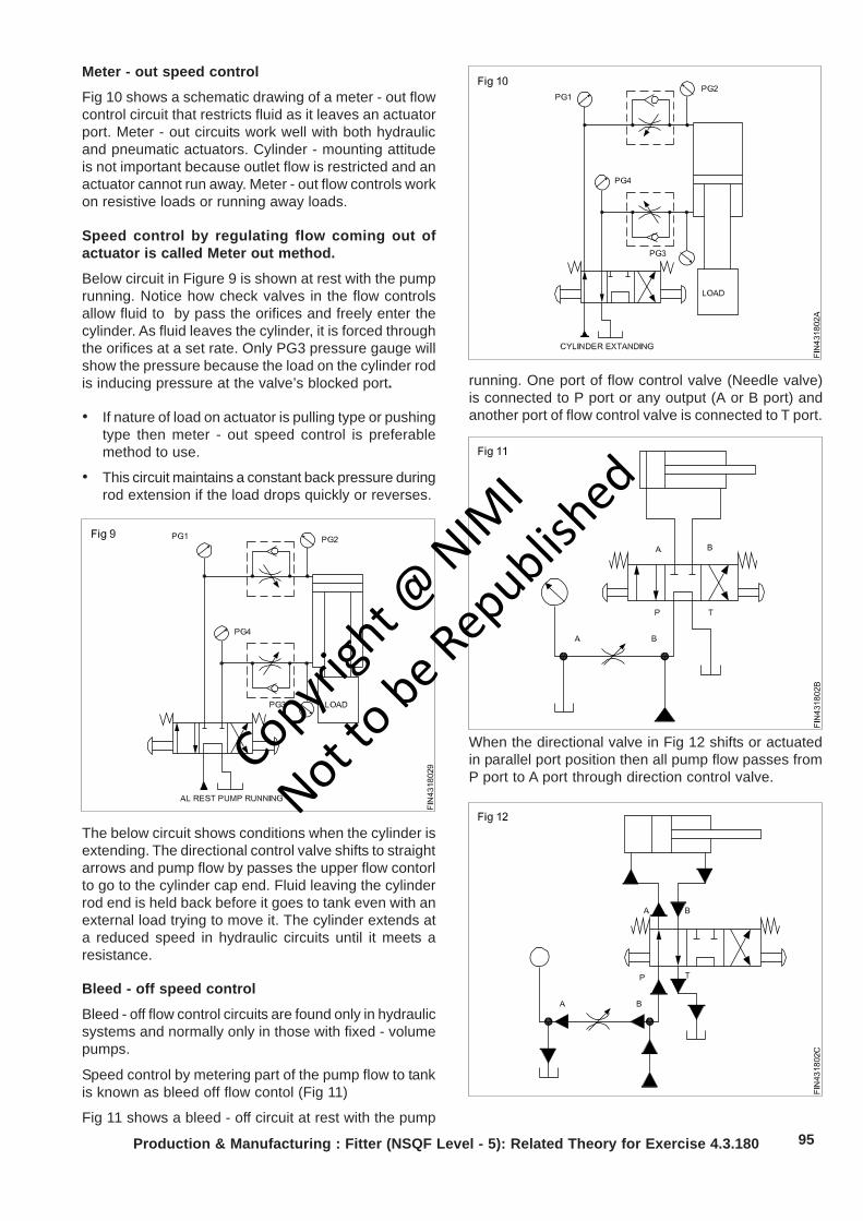
95
Meter - out speed control
Fig 10 shows a schematic drawing of a meter - out flowcontrol circuit that restricts fluid as it leaves an actuatorport. Meter - out circuits work well with both hydraulicand pneumatic actuators. Cylinder - mounting attitudeis not important because outlet flow is restricted and anactuator cannot run away. Meter - out flow controls workon resistive loads or running away loads.
Speed control by regulating flow coming out ofactuator is called Meter out method.
Below circuit in Figure 9 is shown at rest with the pumprunning. Notice how check valves in the flow controlsallow fluid to by pass the orifices and freely enter thecylinder. As fluid leaves the cylinder, it is forced throughthe orifices at a set rate. Only PG3 pressure gauge willshow the pressure because the load on the cylinder rodis inducing pressure at the valve’s blocked port.
• If nature of load on actuator is pulling type or pushingtype then meter - out speed control is preferablemethod to use.
• This circuit maintains a constant back pressure duringrod extension if the load drops quickly or reverses.
running. One port of flow control valve (Needle valve)is connected to P port or any output (A or B port) andanother port of flow control valve is connected to T port.
The below circuit shows conditions when the cylinder isextending. The directional control valve shifts to straightarrows and pump flow by passes the upper flow contorlto go to the cylinder cap end. Fluid leaving the cylinderrod end is held back before it goes to tank even with anexternal load trying to move it. The cylinder extends ata reduced speed in hydraulic circuits until it meets aresistance.
Bleed - off speed control
Bleed - off flow control circuits are found only in hydraulicsystems and normally only in those with fixed - volumepumps.
Speed control by metering part of the pump flow to tankis known as bleed off flow contol (Fig 11)
Fig 11 shows a bleed - off circuit at rest with the pump
When the directional valve in Fig 12 shifts or actuatedin parallel port position then all pump flow passes fromP port to A port through direction control valve.
Production & Manufacturing : Fitter (NSQF Level - 5): Related Theory for Exercise 4.3.180
Copyrigh
t @ NIM
I
Not to be Republish
ed
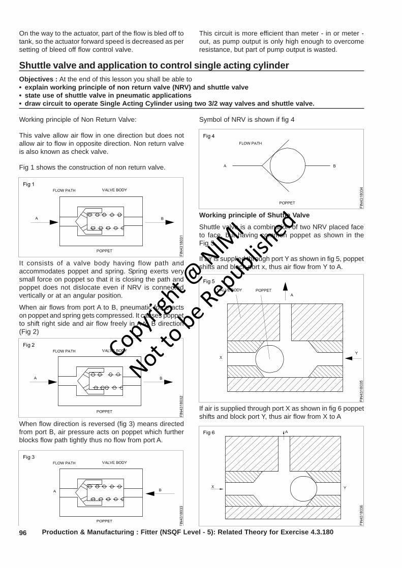
96
Shuttle valve and application to control single acting cylinderObjectives : At the end of this lesson you shall be able to• explain working principle of non return valve (NRV) and shuttle valve• state use of shuttle valve in pneumatic applications• draw circuit to operate Single Acting Cylinder using two 3/2 way valves and shuttle valve.
Working principle of Non Return Valve:
This valve allow air flow in one direction but does notallow air to flow in opposite direction. Non return valveis also known as check valve.
Fig 1 shows the construction of non return valve.
It consists of a valve body having flow path andaccommodates poppet and spring. Spring exerts verysmall force on poppet so that it is closing the path andpoppet does not dislocate even if NRV is connectedvertically or at an angular position.
When air flows from port A to B, pneumatic force actson poppet and spring gets compressed. It causes poppetto shift right side and air flow freely in A to B direction(Fig 2)
Symbol of NRV is shown if fig 4
Production & Manufacturing : Fitter (NSQF Level - 5): Related Theory for Exercise 4.3.180
On the way to the actuator, part of the flow is bled off totank, so the actuator forward speed is decreased as persetting of bleed off flow control valve.
This circuit is more efficient than meter - in or meter -out, as pump output is only high enough to overcomeresistance, but part of pump output is wasted.
When flow direction is reversed (fig 3) means directedfrom port B, air pressure acts on poppet which furtherblocks flow path tightly thus no flow from port A.
Working principle of Shuttle Valve
Shuttle valve is a combination of two NRV placed faceto face, but having common poppet as shown in theFig 5
If air is supplied through port Y as shown in fig 5, poppetshifts and block port x, thus air flow from Y to A.
If air is supplied through port X as shown in fig 6 poppetshifts and block port Y, thus air flow from X to A
Copyrigh
t @ NIM
I
Not to be Republish
ed
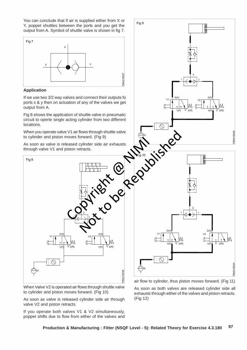
97Production & Manufacturing : Fitter (NSQF Level - 5): Related Theory for Exercise 4.3.180
You can conclude that if air is supplied either from X orY, poppet shuttles between the ports and you get theoutput from A. Symbol of shuttle valve is shown in fig 7.
Application
If we use two 3/2 way valves and connect their outputs foports x & y then on actuation of any of the valves we getoutput from A.
Fig 8 shows the application of shuttle valve in pneumaticcircuit to operte single acting cylinder from two differentlocations.
When you operate valve V1 air flows through shuttle valveto cylinder and piston moves forward. (Fig 9)
As soon as valve is released cylinder side air exhauststhrough valve V1 and piston retracts.
When Valve V2 is operated air flows through shuttle valveto cylinder and piston moves forward. (Fig 10)
As soon as valve is released cylinder side air throughvalve V2 and piston retracts.
If you operate both valves V1 & V2 simultaneously,poppet shifts due to flow from either of the valves and
air flow to cylinder, thus piston moves forward. (Fig 11)
As soon as both valves are released cylinder side allexhausts through either of the valves and piston retracts.(Fig 12)
Copyrigh
t @ NIM
I
Not to be Republish
ed
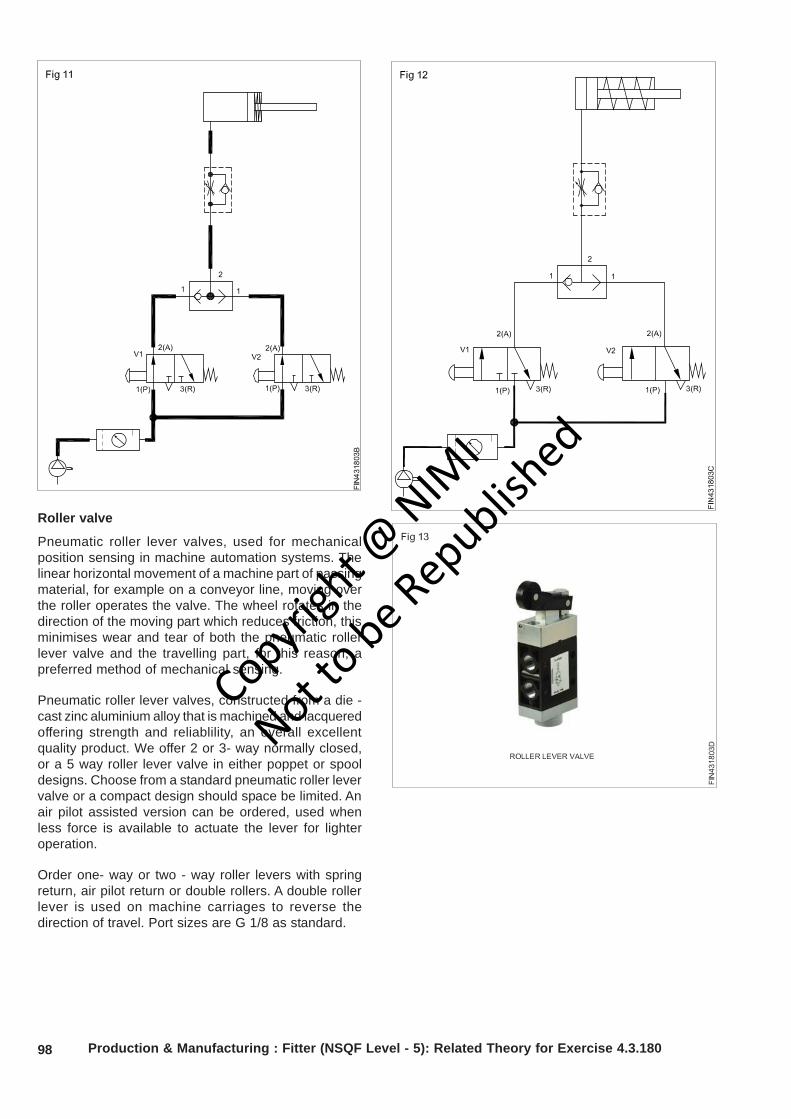
98 Production & Manufacturing : Fitter (NSQF Level - 5): Related Theory for Exercise 4.3.180
Roller valve
Pneumatic roller lever valves, used for mechanicalposition sensing in machine automation systems. Thelinear horizontal movement of a machine part of passingmaterial, for example on a conveyor line, moving overthe roller operates the valve. The wheel rotates in thedirection of the moving part which reduces friction, thisminimises wear and tear of both the pneumatic rollerlever valve and the travelling part, for this reason, apreferred method of mechanical sensing.
Pneumatic roller lever valves, constructed from a die -cast zinc aluminium alloy that is machined and lacqueredoffering strength and reliablility, an overall excellentquality product. We offer 2 or 3- way normally closed,or a 5 way roller lever valve in either poppet or spooldesigns. Choose from a standard pneumatic roller levervalve or a compact design should space be limited. Anair pilot assisted version can be ordered, used whenless force is available to actuate the lever for lighteroperation.
Order one- way or two - way roller levers with springreturn, air pilot return or double rollers. A double rollerlever is used on machine carriages to reverse thedirection of travel. Port sizes are G 1/8 as standard.
Copyrigh
t @ NIM
I
Not to be Republish
ed
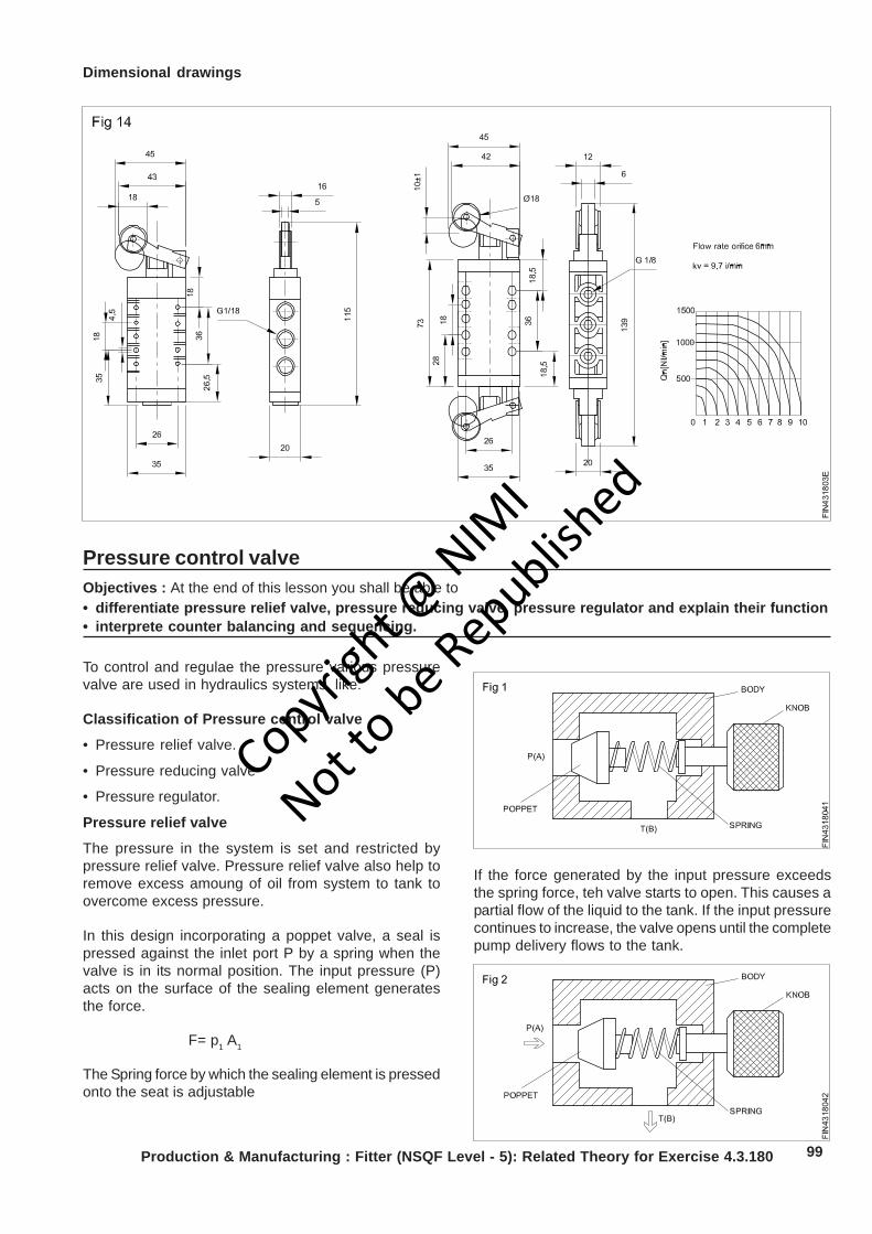
99
Pressure control valveObjectives : At the end of this lesson you shall be able to• differentiate pressure relief valve, pressure reducing valve, pressure regulator and explain their function• interprete counter balancing and sequencing.
To control and regulae the pressure various pressurevalve are used in hydraulics systems, like:
Classification of Pressure control valve
• Pressure relief valve.
• Pressure reducing valve
• Pressure regulator.
Pressure relief valve
The pressure in the system is set and restricted bypressure relief valve. Pressure relief valve also help toremove excess amoung of oil from system to tank toovercome excess pressure.
In this design incorporating a poppet valve, a seal ispressed against the inlet port P by a spring when thevalve is in its normal position. The input pressure (P)acts on the surface of the sealing element generatesthe force.
F= p1 A1
The Spring force by which the sealing element is pressedonto the seat is adjustable
If the force generated by the input pressure exceedsthe spring force, teh valve starts to open. This causes apartial flow of the liquid to the tank. If the input pressurecontinues to increase, the valve opens until the completepump delivery flows to the tank.
Dimensional drawings
Production & Manufacturing : Fitter (NSQF Level - 5): Related Theory for Exercise 4.3.180
Copyrigh
t @ NIM
I
Not to be Republish
ed
100 Production & Manufacturing : Fitter (NSQF Level - 5): Related Theory for Exercise 4.3.180
The resistances at the outlet (tank line. filter) must beadded to the force of the spring in the pressure reliefvalve. Application of PRV is shown in the Fig 3
Pressure reducing valve (2 - way valve)
Pressure regulators reduce the inlet pressure to anadjustable outlet pressure. It is appropriate to use thesein hydraulic system only if different pressures arerequired.
This valve is normally open. The outlet pressure (A)acts via a pilot on the left - hand surface of the pilotpiston against an adjustable spring force. (Fig 4)
When the pressure rises at outlet A, the force at the lefthand surface of the pilot piston becomes increases, thepiston is displaced to the right and the throttle gapbecomes narrower. This causes a pressure drop. In thecase of slide valves, it is also possible to design thecontrol edges in such way that the opening gap increasesonly slowly. This gives greater control precision. (Fig 5)
When the preset maximum pressure is reached, thethrottle point closes completely. (Fig 6)
The pressure at the outlet A of the pressure regulator isless than the system pressure at P and constant. Thepiston rod of the cylinder is now in its forward end
position. Application of pressure reducing valve is shownin the Fig 7
Pressure regulator (3- way Valve)
When the 2 - way pressure regulator close fully, thenany impact vibration in cylinder will responsible toincrease the output pressure above the set value whichis not desirable. One method of rectifying this would beto install a pressure relief valve at the output.
The 3-way pressure regulator can be regarded as acombination of a 2- way pressure regulator (PR) and apressure relief valve (PRV) (Fig 8)
Copyrigh
t @ NIM
I
Not to be Republish
ed
101Production & Manufacturing : Fitter (NSQF Level - 5): Related Theory for Exercise 4.3.180
When the pressure at A raises the result of externalconditions, this pressure acts via a pilot line on the lefthand piston surface of the pilot piston against anadjustable spring force. Every pressure increase causesthe throttle gap to become narrower, resulting in apressure drop. (Figs 9 & 10)
When the maximum preset pressure is reached, thethrottle point closes completely. (Fig 11)
If the pressure rises above the preset value as the resultof an external load at outlet A, the valve opens to allowfrom A to the tank port T (pressure - limiter - function).(Fig 12)
Example of pressure regulator is shown in the fig 13
Pressure regulator help to maintain constant pressurein line and also safe the sytem from excess pressure,so you able to get approximate constant pressure inline.
Counter Balancing
Cylinders with external forces such as weight from aplaten, machine members, or tooling acting against themwill over run when oil flowing out of them is not restricted.A meter - out flow control circuit is one way to controlover running loads but it has one main drawback. A flowcontrol’s speed is fixed except for manual adjustment.Because flow is fixed, the actuator will continue at thesame speed, even when working flow to it increases ordecreases.
The valve which is used to create a back pressureagainst pushing or pulling types of load to maintainnormal speed of cylinder is known ascounterbalance valve.
A counterbalance valve keeps an actuator from runningaway regardless of flow changes because it respondsto pressure signals, not flow. A counter balance valve isalmost the same as a sequence valve. The figure ofcounter balance valve and symbols are shown in Fig 14
A counterbalance valve usually has a bypass checkvalve for reverse flow because its most common use isin controlling actuators with running away or overruningloads.
Fig 15 shows a vertically oriented cylinder with rodfacing down and a load trying to extend it . To keep thecylinder from running away, the counterbalance valvemust resist the load - induced pressure from the weight.
Copyrigh
t @ NIM
I
Not to be Republish
ed
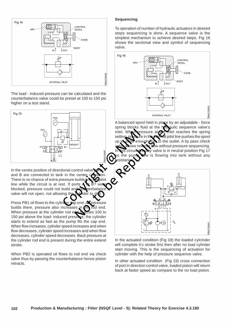
102 Production & Manufacturing : Fitter (NSQF Level - 5): Related Theory for Exercise 4.3.180
The load - induced pressure can be calculated and thecounterbalance valve could be preset at 100 to 150 psihigher on a test stand.
In the centre position of directional control valve ports Aand B are connected to tank in the center condition.There is no chance of extra pressure buildup in the pilotline while the circuit is at rest. If ports A or B? wereblocked, pressure could not build and counterbalancevalve will not open, not allowing the cylinder to drift.
Press PB1 oil flows to the cylinder cap end. As pressurebuilds there, pressure also increases in the rod end.When pressure at the cylinder rod end reaches 100 to150 psi above the load- induced pressure, the cylinderstarts to extend as fast as the pump fils the cap end.When flow increases, cylinder speed increases and whenflow decreases, cylinder speed increases and when flowdecreases, cylinder speed decreases. Back pressure atthe cylinder rod end is present during the entire extendstroke.
When PB2 is operated oil flows to rod end via checkvalve thus by passing the counterbalance hence pistonretracts.
Sequencing
To operation of number of hydraulic actuators in desiredsteps sequencing is done. A sequence valve is thesimplest mechanism to achieve desired steps. Fig 16shows the sectional view and symbol of sequencingvalve.
A balanced spool held in place by an adjustable - forcespring blocks fluid at the hydraulic sequence valve’sinlet. When pressure at the inlet reaches the springsetting, pressure in the internal pilot line pushes the spoolup to allow enough flow to the outlet. A by pass checkvalve allows reverse flow without pressure sequencing.In this circuit 4/3 way valve is in neutral position Fig 17so the pump flow is flowing into tank without anyresistance.
In the actuated condition (Fig 18) the loaded cylcinderwill complete it’s stroke first then after no load cylinderstart moving. This is the sequencing of actuation forcylinder with the help of pressure sequence valve.
In other actuated condition (Fig 19) cross connectionof port in direction control valve, loaded piston will returnback at faster speed as compare to the no load piston.
Copyrigh
t @ NIM
I
Not to be Republish
ed

103Production & Manufacturing : Fitter (NSQF Level - 5): Related Theory for Exercise 4.3.180
Copyrigh
t @ NIM
I
Not to be Republish
ed

104
Production & Manufacturing Related Theory for Exercie 4.3.181Fitter - Hydraulics & Pneumatics
Electro- pneumaticsObjectives : At the end of this lesson you shall be able to• explain about the electro pneumatic control system• list the basic electrical devices• explain the operation of switches• describe the purpose and constructional details of solenoid valves.• explain purpose and operation of relay.
Introduction
Electro pneumatic control consists of electrical controlsystems operating pneumatic power system. In thissolenoid valves, are used as interface between theelectrical and pneumatic system. Devices like switchesare used as feedback elements.
In electro pneumatics, the signal medium is the electricalsignal either AC or DC source is used. Working mediumis compressed air. Operating voltages from around 12vto 220 v are used. The final control valve is actuated bysolenoid activation.
In electro pneumatic controls, mainly three importantsteps are involved.
Signal input devices
Signal generation such as switches and contactor, varioustypes of contact and proximity sensors.
Signal processing
Use of combination of contactors of relay or usingprogrammable logic controllers.
Signal outputs
Outputs obtained after processing are used for activationof solenoids, indicators or audible alarms.
Basic electrical devices
Basic electrical devices commonly used in the control offluid power systems are
Manually actuated push button switchesLimit switchesPressure switchesSolenoidsRelaysTemperature switches
Push button switches
A push button is a switch used to close or open an electriccontrol circuit. They are primarily used for starting andstopping of operation of machinery. They also provide
manual over ride when the emergency arises. Pushbutton switches are actuated by pushing the actuatorinto the housing. This causes set of contacts to open orclose.
Push buttons are of two types
Momentary push button
Maintained contact or detent push button
Momentary push buttons return to their unactuatedposition when they are released. Maintained (ormechanically latched) push buttons has a latchingmechanism to hold it in the selected position.
The contact of the push buttons, distinguished accordingto their functions.
- Normally open (NO) type
- Normally closed (NC) type
- Change over (CO) type.
The cross section of various types of push buttons in thenormal and actuated positions and their symbols aregiven in the fig 1. In the NO type, the contacts are openin the normal position, inhibiting the energy flow throughthem. But in the actuated position, the contacts areclosed, permitting the energy flow through them. In theNC type, the contacts are closed in the normal position,permitting the energy flow through them. And, thecontacts are open in the actuated position, inhibiting theenergy flow through them. A changeover contact is acombination of NO and NC contacts.
Type of devices Terminal numbers
Normally Normally closed contacts open contacts
Push buttons 1 and 2 3 and 4 and relays
Limit switches
Any switch that is actuated due to the position of a fluidpower component (usually a piston rod or hydraulicmotor shaft or the position of load is termed as limitswitch. The actuation of a limit switch provides anelectrical signal that causes an appropriate systemresponse.
Copyrigh
t @ NIM
I
Not to be Republish
ed
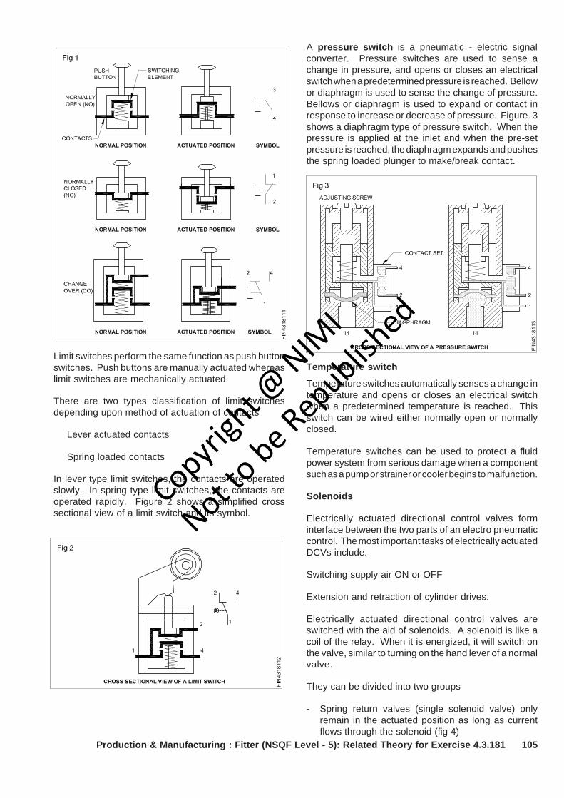
105
A pressure switch is a pneumatic - electric signalconverter. Pressure switches are used to sense achange in pressure, and opens or closes an electricalswitch when a predetermined pressure is reached. Bellowor diaphragm is used to sense the change of pressure.Bellows or diaphragm is used to expand or contact inresponse to increase or decrease of pressure. Figure. 3shows a diaphragm type of pressure switch. When thepressure is applied at the inlet and when the pre-setpressure is reached, the diaphragm expands and pushesthe spring loaded plunger to make/break contact.
Production & Manufacturing : Fitter (NSQF Level - 5): Related Theory for Exercise 4.3.181
Temperature switch
Temperature switches automatically senses a change intemperature and opens or closes an electrical switchwhen a predetermined temperature is reached. Thisswitch can be wired either normally open or normallyclosed.
Temperature switches can be used to protect a fluidpower system from serious damage when a componentsuch as a pump or strainer or cooler begins to malfunction.
Solenoids
Electrically actuated directional control valves forminterface between the two parts of an electro pneumaticcontrol. The most important tasks of electrically actuatedDCVs include.
Switching supply air ON or OFF
Extension and retraction of cylinder drives.
Electrically actuated directional control valves areswitched with the aid of solenoids. A solenoid is like acoil of the relay. When it is energized, it will switch onthe valve, similar to turning on the hand lever of a normalvalve.
They can be divided into two groups
- Spring return valves (single solenoid valve) onlyremain in the actuated position as long as currentflows through the solenoid (fig 4)
Limit switches perform the same function as push buttonswitches. Push buttons are manually actuated whereaslimit switches are mechanically actuated.
There are two types classification of limit switchesdepending upon method of actuation of contacts
Lever actuated contacts
Spring loaded contacts
In lever type limit switches, the contacts are operatedslowly. In spring type limit switches, the contacts areoperated rapidly. Figure 2 shows a simplified crosssectional view of a limit switch and its symbol.
Copyrigh
t @ NIM
I
Not to be Republish
ed
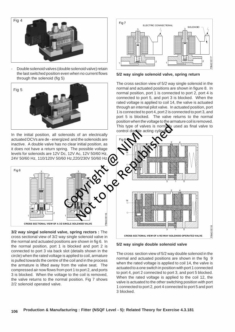
106
- Double solenoid valves (double solenoid valve) retainthe last switched position even when no current flowsthrough the solenoid (fig 5)
In the initial position, all solenoids of an electricallyactuated DCVs are de - energized and the solenoids areinactive. A double valve has no clear initial position, asit does not have a return spring. The possible voltagelevels for solenoids are 12V Dc, 12V Ac, 12V 50/60 Hz,24V 50/60 Hz, 110/120V 50/60 Hz,220/230V 50/60 Hz
3/2 way singal solenoid valve, spring rectors : Thecross sectional view of 3/2 way single solenoid valve inthe normal and actuated positions are shown in fig 6. Inthe normal position, port 1 is blocked and port 2 isconnected to port 3 via back slot (details shown in thecircle) when the rated voltage is applied to coil, armatureis pulled towards the centre of the coil and in the processthe armature is lifted away from the valve seat. Thecompressed air now flows from port 1 to port 2, and ports3 is blocked. When the voltage to the coil is removed,the valve returns to the normal position. Fig 7 shows2/2 solenoid operated valve.
Production & Manufacturing : Fitter (NSQF Level - 5): Related Theory for Exercise 4.3.181
5/2 way single solenoid valve, spring return
The cross section view of 5/2 way single solenoid in thenormal and actuated positions are shown in figure 8. Innormal position, port 1 is connected to port 2, port 4 isconnected to port 5, and port 3 is blocked. When therated voltage is applied to coil 14, the valve is actuatedthrough an internal pilot valve. In actuated position, port1 is connected to port 4, port 2 is connected to port 3, andport 5 is blocked. The valve returns to the normalposition when the voltage to the armature coil is removed.This type of valves is normally used as final valve tocontrol double acting cylinders.
5/2 way single double solenoid valve
The cross section view of 5/2 way double solenoid in thenormal and actuated positions are shown in the fig 9when the rated voltage is applied to coil 14, the valve isactuated to a one switch in position with port 1 connectedto port 4, port 2 connected to port 3, and port 5 blocked.When the rated voltage is applied to the coil 12, thevalve is actuated to the other switching position with port1 connected to port 2, port 4 connected to port 5 and port3 blocked.
Fig 4
Fig 5
Copyrigh
t @ NIM
I
Not to be Republish
ed
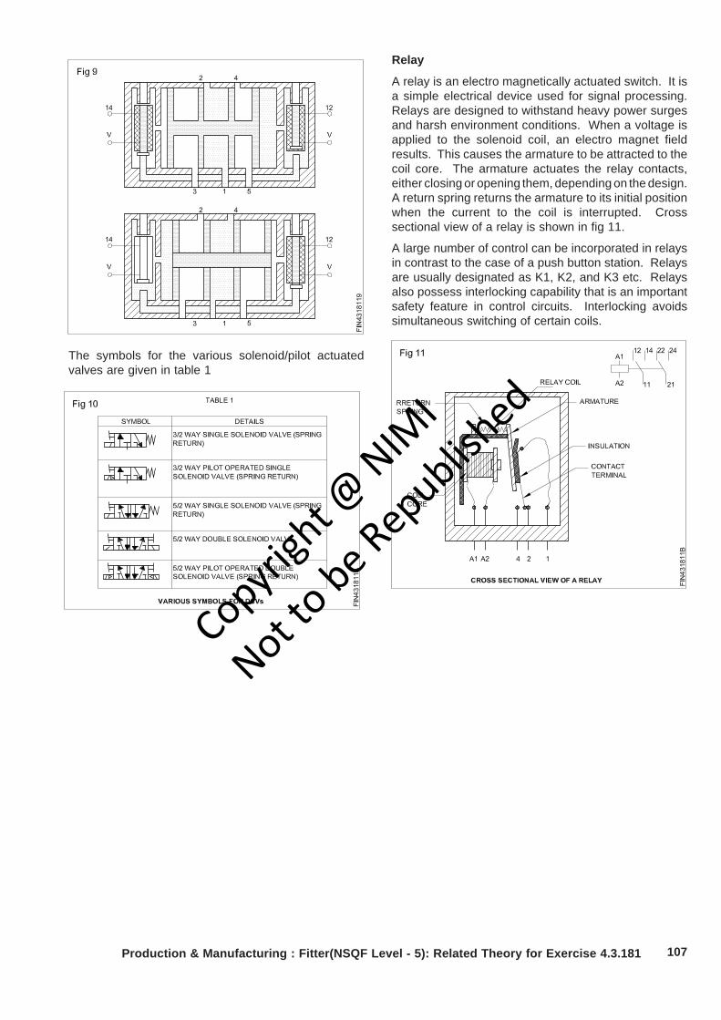
107Production & Manufacturing : Fitter(NSQF Level - 5): Related Theory for Exercise 4.3.181
The symbols for the various solenoid/pilot actuatedvalves are given in table 1
Relay
A relay is an electro magnetically actuated switch. It isa simple electrical device used for signal processing.Relays are designed to withstand heavy power surgesand harsh environment conditions. When a voltage isapplied to the solenoid coil, an electro magnet fieldresults. This causes the armature to be attracted to thecoil core. The armature actuates the relay contacts,either closing or opening them, depending on the design.A return spring returns the armature to its initial positionwhen the current to the coil is interrupted. Crosssectional view of a relay is shown in fig 11.
A large number of control can be incorporated in relaysin contrast to the case of a push button station. Relaysare usually designated as K1, K2, and K3 etc. Relaysalso possess interlocking capability that is an importantsafety feature in control circuits. Interlocking avoidssimultaneous switching of certain coils.
Copyrigh
t @ NIM
I
Not to be Republish
ed
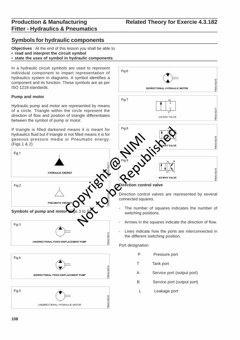
108
Production & Manufacturing Related Theory for Exercie 4.3.182Fitter - Hydraulics & Pneumatics
Symbols for hydraulic componentsObjectives : At the end of this lesson you shall be able to• read and interpret the circuit symbol• state the uses of symbol in hydraulic components
In a hydraulic circuit symbols are used to representindividual component to impart representation ofhydraulics system in diagrams. A symbol identifies acomponent and its function. These symbols are as perISO 1219 standards.
Pump and motor
Hydraulic pump and motor are represented by meansof a circle. Triangle within the circle represent thedirection of flow and position of triangle differentiatesbetween the symbol of pump or motor.
If triangle is filled darkened means it is meant forhydraulics fluid but if triangle is not filled means it is forgaseous pressure media or Pneumatic energy.(Figs 1 & 2)
Symbols of pump and motor (Figs 3 to 9)
Direction control valve
Direction control valves are represented by severalconnected squares.
- The number of squares indicates the number ofswitching positions.
- Arrows in the squares indicate the direction of flow.
- Lines indicate how the ports are interconnected inthe different switching position.
Port designation
P Pressure port
T Tank port
A Service port (output port)
B Service port (output port)
L Leakage port
Copyrigh
t @ NIM
I
Not to be Republish
ed
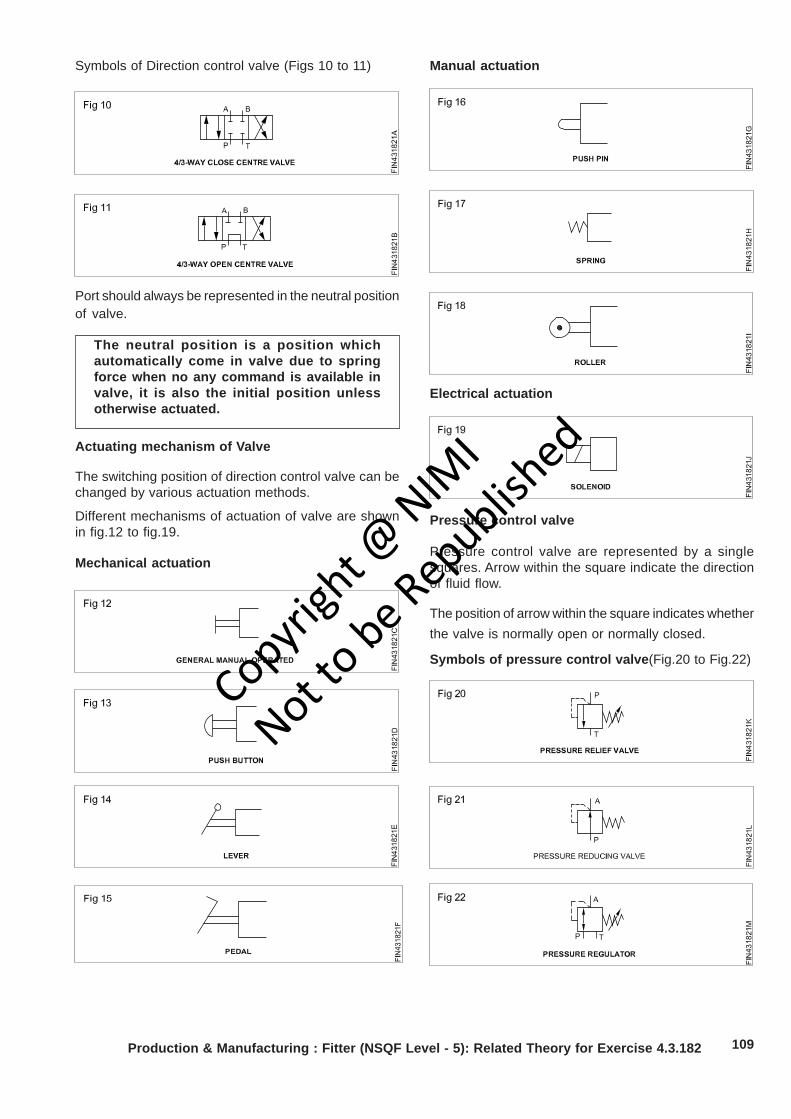
109
Symbols of Direction control valve (Figs 10 to 11) Manual actuation
Electrical actuation
Production & Manufacturing : Fitter (NSQF Level - 5): Related Theory for Exercise 4.3.182
Port should always be represented in the neutral positionof valve.
The neutral position is a position whichautomatically come in valve due to springforce when no any command is available invalve, it is also the initial position unlessotherwise actuated.
Pressure control valve
Pressure control valve are represented by a singlesquares. Arrow within the square indicate the directionof fluid flow.
The position of arrow within the square indicates whetherthe valve is normally open or normally closed.
Symbols of pressure control valve(Fig.20 to Fig.22)
Actuating mechanism of Valve
The switching position of direction control valve can bechanged by various actuation methods.
Different mechanisms of actuation of valve are shownin fig.12 to fig.19.
Mechanical actuation
Copyrigh
t @ NIM
I
Not to be Republish
ed
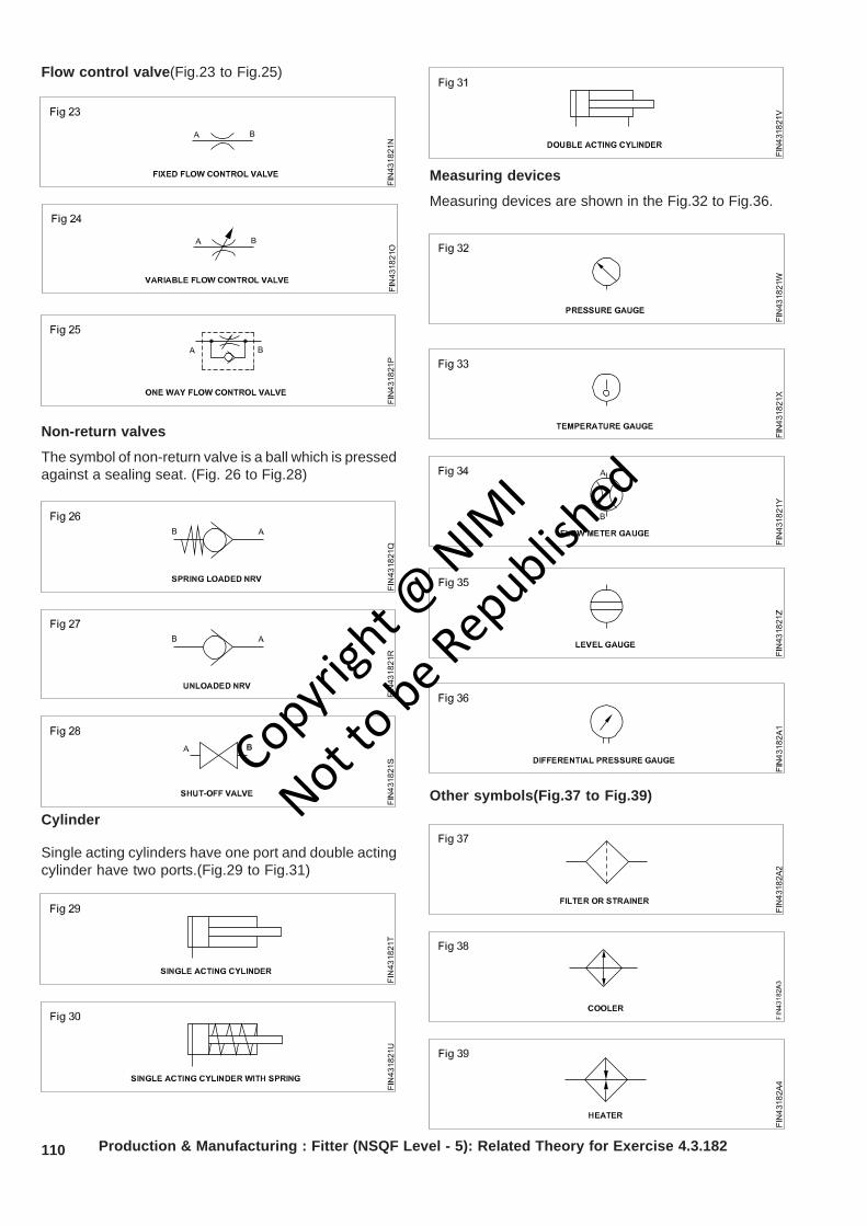
110 Production & Manufacturing : Fitter (NSQF Level - 5): Related Theory for Exercise 4.3.182
Flow control valve(Fig.23 to Fig.25)
Non-return valves
The symbol of non-return valve is a ball which is pressedagainst a sealing seat. (Fig. 26 to Fig.28)
Cylinder
Single acting cylinders have one port and double actingcylinder have two ports.(Fig.29 to Fig.31)
Measuring devices
Measuring devices are shown in the Fig.32 to Fig.36.
Other symbols(Fig.37 to Fig.39)
Copyrigh
t @ NIM
I
Not to be Republish
ed
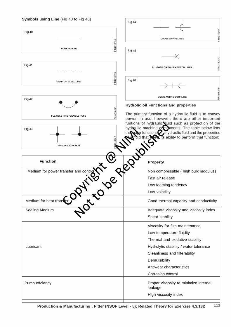
111Production & Manufacturing : Fitter (NSQF Level - 5): Related Theory for Exercise 4.3.182
Property
Medium for power transfer and control Non compressible ( high bulk modulus)
Fast air release
Low foaming tendency
Low volatility
Medium for heat transfer Good thermal capacity and conductivity
Sealing Medium Adequate viscosity and viscosity index
Shear stability
Viscosity for flim maintenance
Low temperature fluidity
Thermal and oxidative stability
Lubricant Hydrolytic stability / water tolerance
Cleanliness and filterability
Demulsibility
Antiwear characteristics
Corrosion control
Pump effciency Proper viscosity to minimize internalleakage
High viscosity index
Symbols using Line (Fig 40 to Fig 46)
Hydrolic oil Functions and properties
The primary function of a hydraulic fluid is to conveypower. In use, however, there are other importantfuntions of hydraulic fluid such as protection of thehydraulic machine components. The table below liststhe major functions of a hydraulic fluid and the propertiesof a fluid that affect its ability to perform that function:
Function
Copyrigh
t @ NIM
I
Not to be Republish
ed
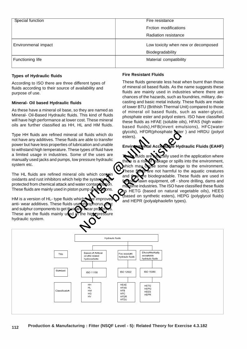
112
Special function Fire resistance
Frction modifications
Radiation resistance
Environmenal impact Low toxicity when new or decomposed
Biodegradability
Functioning life Material compatibility
Types of Hydraulic fluids
According to ISO there are three different types offluids according to their source of availability andpurpose of use.
Mineral- Oil based Hydraulic fluids
As these have a mineral oil base, so they are named asMineral- Oil-Based Hydraulic fluids. This kind of fluidswill have high performance at lower cost. These mineraloils are further classified as HH, HL and HM fluids.
Type HH fluids are refined mineral oil fluids which donot have any additives. These fluids are able to transferpower but have less properties of lubrication and unableto withstand high temperature. These types of fluid havea limited usage in industries. Some of the uses aremanually used jacks and pumps, low pressure hydraulicsystem etc.
The HL fluids are refined mineral oils which containoxidants and rust inhibitors which help the system to beprotected from chemical attack and water contamination.These fluids are mainly used in piston pump applications.
HM is a version of HL- type fluids which have improvedanti- wear additives. These fluids use phosphorus, zincand sulphur components to get their anti-wear properties.These are the fluids mainly used in the high pressurehydraulic system.
Fire Resistant Fluids
These fluids generate less heat when burnt than thoseof mineral oil based fluids. As the name suggests thesefluids are mainly used in industries where there arechances of the hazards, such as foundries, military, die-casting and basic metal industy. These fluids are madeof lower BTU (Brithish Thermal Unit) compared to thoseof mineral oil based fluids, such as water-glycol,phosphate ester and polyol esters. ISO have classifiedthese fluids as HFAE (soluble oils), HFAS (high water-based fluids),HFB(invert emulsions), HFC(waterglycols), HFDR(phosphate ester ) and HRDU (polyolesters).
Environmental Acceptable Hydraulic Fluids (EAHF)
These fluids are basically used in the application wherethere is a risk of leakage or spills into the environment,which may cause some damage to the environment.These fluids are not harmful to the aquatic creaturesand they are biodegradable. These fluids are used inforestry, lawn equipment, off - shore drilling, dams andmaritime industries. The ISO have classified these fluidsas HETG (based on natural vegetable oils), HEES(based on synthetic esters), HEPG (polyglycol fluids)and HEPR (polyalphaolefin types).
Production & Manufacturing : Fitter (NSQF Level - 5): Related Theory for Exercise 4.3.182
Copyrigh
t @ NIM
I
Not to be Republish
ed

113
Controlling of Contamination
While the fluid is at operating temperature, completelydrain the system. paying attention to the reservoir, alllines, cylinders, accumulators, filter housings or any areaof fluid accumlation. Also, replace the filters.
With a lint-free rag, clean the reservoir of all sludge anddeposits. Make sure the entire reservoir is free of anysoft or loosened paint.
Flush the system with a lower viscosity fluid that is similarto the fluid to be used. A Reynolds number between2,000 and 4,000 should be selected to achieve enoughturbulence to remove particles from the lines. Strokevalves frequently to ensure they are thoroughly flushed.The fluid should be filtered and the flushing shouldcontinue until reaching one level beyond the system’starget cleanliness levels. For example,if the target isISO 15/13/11, continue to flush the system until ISO14/12/10 is reached.
Drain the flushing fluid as hot and as quickly as possible.Replace the filters and inspect/ clean the reservoir again.
Fill the system to approximately 75 percent with thefluid to be used. Bleed/vent the pump.If the pump has apressure relief or bypass, it should be wide open. Runthe pump for 15 seconds, then stop and let it sit for 45seconds. Repeat this procedure a few times to primethe pump.
Run the pump for a minute with the bypass or pressurerelief open. Stop the pump and let it sit for a minute.Close the bypass and permit the pump to operate loadedfor no more than five minutes. Allow the relief valve tolift to confirm that it is flushed as well. Do not operatethe actuators at this time. Stop the pump and let thesystem sit for about five minutes.
Start the pump and operate the actuators one at a time,allowing fluid to return to the reservoir before moving tothe next actuator. After operating the final actuator, shutdown the system. Keep an eye on the fluid level in thereservoir. If the level drops below 25 percent, add fluidand fill to 50 percent.
Refill the reservoir to 75 percent and run the system infive- minute intervals. At each shutdown, bleed the airfrom the system. Pay close attention to the systemsounds to determine if the pump is cavitating.
Run the system for 30 minutes to bring it to normaloperating temperature. shutdown the system and replacethe filters. Inspect the reservoir for obvious signs ofcross-contamination. If any indication of cross-contamination is present, drain and flush the systemagain.
After six hours of operation, shut down the system,replace the filters and sample and test the fluid.
The sampling frequency should be increased until youare confident that the system fluid is stable.
Contamination of oil and its control
Contamination in hydraulic systems can be classifiedinto particle contaminants (Metal particles from wear,dirtingression) or chemical contaminants (water, air ,heat,etc). Examples of damage from contamination are:accelerated component wear, orifice blockage, formationof rust or other oxidation, depletion of additives,formation of other chemicals, oil degradation.
Types of contamination
Particle contaminants
Particle sizes are generally measured in micrometersor microns. Some examples of microns: Grain of salt100 microns, human hair 70 microns, lower limit ofvisibility 40 micron, milled flour 25 micron, averagebacteria 2 micron. Note that most damage-causingparticles in hydraulic or lubrication systems are smallerthan 14 μm micrometers, so they cannot be seen.
Chemical contaminants
Water
The most common chemical contaminant in hydraulicsystems is water. The presence of water in hydraulic oilcan have wide- ranging effects on system componentsbecause of its effect on the physical and chemicalproperties of hydraulic oil. Rust in tanks, reducedlubrication characteristics resulting in accelerated metalsurface wear are some of the most obvious physicalresults of excessive water, however the effects couldbe as diverse as the jamming of components due to icecrystals at low temperatures. Chemical effects includeadditive depletion or deposition, oxidation, unwantedreactions which can result in the formation of acids,alcohols or sludges. Oil becomes cloudy when it’scontaminated with water above its saturation level. Thesaturation level is the amount of water that can dissolvein the oil’s molecular chemistry and is typically 200 to300 ppm at 20° C for mineral hydraulic oil. SKF statethat hydraulic oil containing just 0.1% water by volumecuts bearing life in half, while 1% reduces bearing lifeby 75%
Air
Air in hydraulic system can exist in either a dissolved orentrained (undissolved, or free) state. Dissolved air maynot pose a problem, providing it stays in solution. Whena liquid contains undissolved air, problems can occuras it passes through system components. There can bepressure changes that compress the air and produce alarge amount of heat in small air bubbles. Thiscompressibility of air means that control of the systemis lost. Air bubbles and frothing in the oil reservoir cancause major damage to pumps or it can also cause oilto “boil” out of the tank.
Heat
Excessive heat in hydraulic systems can also result inadditive depletion or chemical changes to the oil.
Production & Manufacturing : Fitter (NSQF Level - 5): Related Theory for Exercise 4.3.182
Copyrigh
t @ NIM
I
Not to be Republish
ed
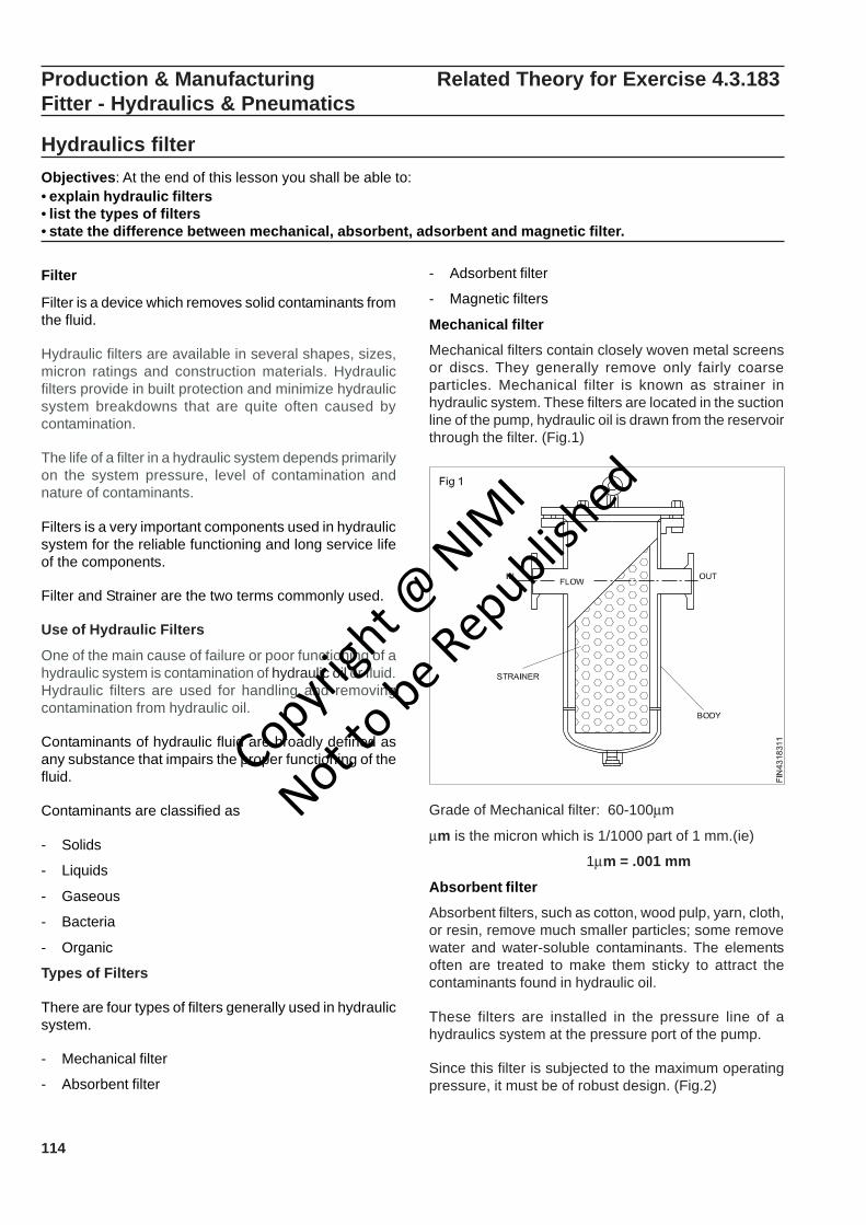
114
- Adsorbent filter
- Magnetic filters
Mechanical filter
Mechanical filters contain closely woven metal screensor discs. They generally remove only fairly coarseparticles. Mechanical filter is known as strainer inhydraulic system. These filters are located in the suctionline of the pump, hydraulic oil is drawn from the reservoirthrough the filter. (Fig.1)
Production & Manufacturing Related Theory for Exercise 4.3.183Fitter - Hydraulics & Pneumatics
Hydraulics filterObjectives: At the end of this lesson you shall be able to:• explain hydraulic filters• list the types of filters• state the difference between mechanical, absorbent, adsorbent and magnetic filter.
Filter
Filter is a device which removes solid contaminants fromthe fluid.
Hydraulic filters are available in several shapes, sizes,micron ratings and construction materials. Hydraulicfilters provide in built protection and minimize hydraulicsystem breakdowns that are quite often caused bycontamination.
The life of a filter in a hydraulic system depends primarilyon the system pressure, level of contamination andnature of contaminants.
Filters is a very important components used in hydraulicsystem for the reliable functioning and long service lifeof the components.
Filter and Strainer are the two terms commonly used.
Use of Hydraulic Filters
One of the main cause of failure or poor functioning of ahydraulic system is contamination of hydraulic oil or fluid.Hydraulic filters are used for handling and removingcontamination from hydraulic oil.
Contaminants of hydraulic fluid are broadly defined asany substance that impairs the proper functioning of thefluid.
Contaminants are classified as
- Solids
- Liquids
- Gaseous
- Bacteria
- Organic
Types of Filters
There are four types of filters generally used in hydraulicsystem.
- Mechanical filter
- Absorbent filter
Grade of Mechanical filter: 60-100μm
μm is the micron which is 1/1000 part of 1 mm.(ie)
1μm = .001 mm
Absorbent filter
Absorbent filters, such as cotton, wood pulp, yarn, cloth,or resin, remove much smaller particles; some removewater and water-soluble contaminants. The elementsoften are treated to make them sticky to attract thecontaminants found in hydraulic oil.
These filters are installed in the pressure line of ahydraulics system at the pressure port of the pump.
Since this filter is subjected to the maximum operatingpressure, it must be of robust design. (Fig.2)
Copyrigh
t @ NIM
I
Not to be Republish
ed
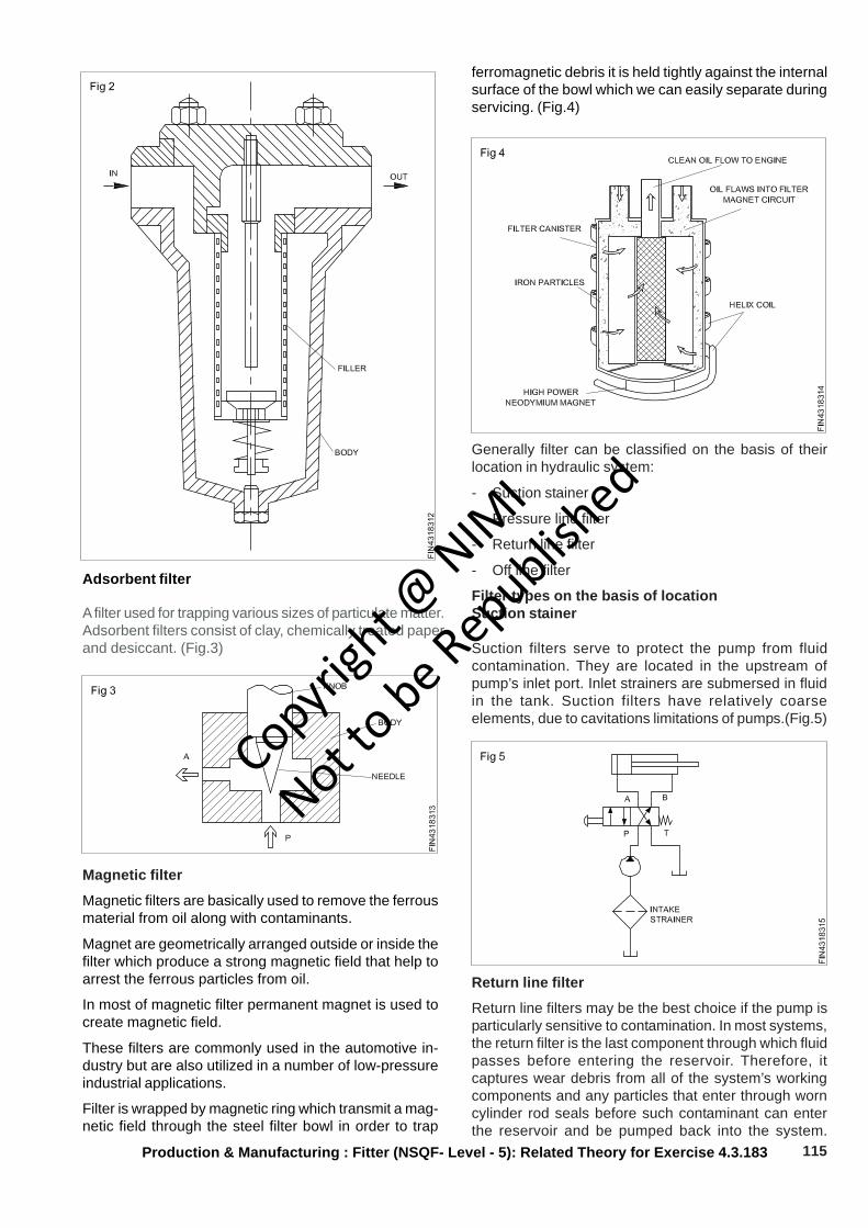
115Production & Manufacturing : Fitter (NSQF- Level - 5): Related Theory for Exercise 4.3.183
Adsorbent filter
A filter used for trapping various sizes of particulate matter.Adsorbent filters consist of clay, chemically treated paperand desiccant. (Fig.3)
Magnetic filter
Magnetic filters are basically used to remove the ferrousmaterial from oil along with contaminants.
Magnet are geometrically arranged outside or inside thefilter which produce a strong magnetic field that help toarrest the ferrous particles from oil.
In most of magnetic filter permanent magnet is used tocreate magnetic field.
These filters are commonly used in the automotive in-dustry but are also utilized in a number of low-pressureindustrial applications.
Filter is wrapped by magnetic ring which transmit a mag-netic field through the steel filter bowl in order to trap
ferromagnetic debris it is held tightly against the internalsurface of the bowl which we can easily separate duringservicing. (Fig.4)
Generally filter can be classified on the basis of theirlocation in hydraulic system:
- Suction stainer
- Pressure line filter
- Return line filter
- Off line filter
Filter types on the basis of locationSuction stainer
Suction filters serve to protect the pump from fluidcontamination. They are located in the upstream ofpump’s inlet port. Inlet strainers are submersed in fluidin the tank. Suction filters have relatively coarseelements, due to cavitations limitations of pumps.(Fig.5)
Return line filter
Return line filters may be the best choice if the pump isparticularly sensitive to contamination. In most systems,the return filter is the last component through which fluidpasses before entering the reservoir. Therefore, itcaptures wear debris from all of the system’s workingcomponents and any particles that enter through worncylinder rod seals before such contaminant can enterthe reservoir and be pumped back into the system.
Copyrigh
t @ NIM
I
Not to be Republish
ed
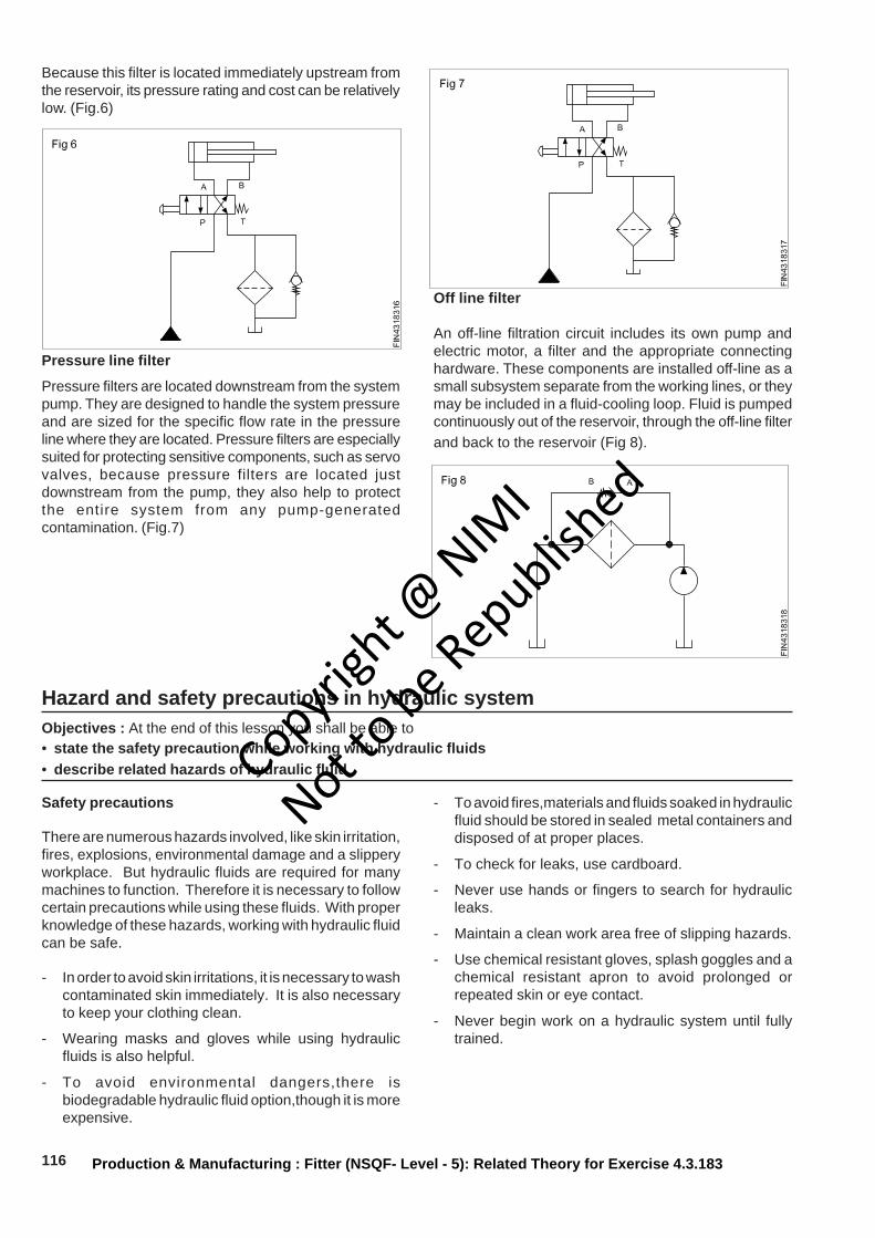
116 Production & Manufacturing : Fitter (NSQF- Level - 5): Related Theory for Exercise 4.3.183
Because this filter is located immediately upstream fromthe reservoir, its pressure rating and cost can be relativelylow. (Fig.6)
Pressure line filter
Pressure filters are located downstream from the systempump. They are designed to handle the system pressureand are sized for the specific flow rate in the pressureline where they are located. Pressure filters are especiallysuited for protecting sensitive components, such as servovalves, because pressure filters are located justdownstream from the pump, they also help to protectthe entire system from any pump-generatedcontamination. (Fig.7)
Off line filter
An off-line filtration circuit includes its own pump andelectric motor, a filter and the appropriate connectinghardware. These components are installed off-line as asmall subsystem separate from the working lines, or theymay be included in a fluid-cooling loop. Fluid is pumpedcontinuously out of the reservoir, through the off-line filterand back to the reservoir (Fig 8).
Hazard and safety precautions in hydraulic systemObjectives : At the end of this lesson you shall be able to• state the safety precaution while working with hydraulic fluids• describe related hazards of hydraulic fluid
Safety precautions
There are numerous hazards involved, like skin irritation,fires, explosions, environmental damage and a slipperyworkplace. But hydraulic fluids are required for manymachines to function. Therefore it is necessary to followcertain precautions while using these fluids. With properknowledge of these hazards, working with hydraulic fluidcan be safe.
- In order to avoid skin irritations, it is necessary to washcontaminated skin immediately. It is also necessaryto keep your clothing clean.
- Wearing masks and gloves while using hydraulicfluids is also helpful.
- To avoid environmental dangers,there isbiodegradable hydraulic fluid option,though it is moreexpensive.
- To avoid fires,materials and fluids soaked in hydraulicfluid should be stored in sealed metal containers anddisposed of at proper places.
- To check for leaks, use cardboard.
- Never use hands or fingers to search for hydraulicleaks.
- Maintain a clean work area free of slipping hazards.
- Use chemical resistant gloves, splash goggles and achemical resistant apron to avoid prolonged orrepeated skin or eye contact.
- Never begin work on a hydraulic system until fullytrained.
Copyrigh
t @ NIM
I
Not to be Republish
ed
117Production & Manufacturing : Fitter (NSQF- Level - 5): Related Theory for Exercise 4.3.183
Related hazards
Health problems while using hydraulic fluids
People can become exposed to the chemicals in hydraulicfluids. The exposure to chemicals may be due toinhalation, ingestion or touch. There are instances ofpeople suffering from skin irritation or weakness in handswhile handling hydraulic fluids. There are also cases ofintestinal bleeding, pneumonia or death through hydraulicfluid ingestion though no serious hazards are reportedwith hydraulic fluid inhalation.
Similar to ingestion, fluids can be accidentally injectedinto the skin as well. This takes place when the highpressure hydraulic system hose is disconnected andtoxic fluids are leaked and injected into the skin. If thereis a small leak in the hydraulic pipe and someone runsthere hand along it, at 2000 psi, they can easily incur aninjection of hydraulic fluid and may not even be aware thatit happened until gangrene begins to set in.
Fire dangers associated with hydraulic fluids
When working with hydraulic fluid, there is every chancethat the hydraulic fluid gets heated to high temperatures.And it is evident that most petroleum - based hydraulicfluids will burn and thereby create explosions and burns.
Environmental problems related to hydraulic fluids
Another hazard of hydraulic fluid is that when the hydraulichose or pipe leaks, the chemicals of the fluids can eitherstay on top of the soil or sink into the ground. If thechemicals get mixed in a water body, they will sink to thebottom. In fact in such cases the chemicals can staythere for more than a year. Aquatic life can absorb thetoxic hydraulic fluid, leading to illness or death to theanimal or anything higher on the food chain. For example,a hawk that eats a fish that has been contaminated byhydraulic fluid that was mixed in water could become ill aswell.
Fluid texture problems
Although the slimy texture of hydraulic fluids may notseem like a danger or a problem, a spill can cause aperson to slip and fall. Also when there is fluid on thehands of a person, it can cause him to slip while climbingon a machine. It can also cause the operator to losesteering control.
Injuries from loose hydraulic hoses
Due to high pressure with in a hydraulic system, theimpact force of a disconnected and flailing hydraulic hosecan cause abrasions, temporary unconsciousness,bruise, fractures and laserations. Proper maintenanceand good pre - shift equipment inspections can minimisethese hazards
Copyrigh
t @ NIM
I
Not to be Republish
ed
118
Types of Hydraulic pumps(Fig. 4)
External Gear pump
External gear pump is the most common type rotarypump. In this pump the drive gear is turned by a driveshaft, which engages the power source. The inlet port isconnected to the supply line and the outlet is connectedto the pressure line. (Fig.5)
As gears rotate the volume of area on the inlet increases,thereby decreasing the pressure and making it possiblefor the atmospheric pressure exerted on the surface of
Production & Manufacturing Related Theory for Exercise 4.3.184Fitter - Hydraulics & Pneumatics
Hydraulic pumpsObjectives : At the end of this lesson you shall be able to• define hydraulic pump• differentiate between positive and non-positive displacement pump• explain working of gear pump• explain the working of vane pump• explain the working of piston pump.
A hydraulic pump fig.1 is a device which convertsmechanical force and motion into hydraulic energy. Manydifferent sources provide mechanical power to the pump.They are electric motors, air motors, engines and manualoperation.
Classification of pumps
Pumps are classified as either non-positive or positivedisplacement. This describes the fundamental divisionof pumps.
Non-positive displacement pumps
- The non-positive displacement type pump givescontinuous discharge.
- The non-positive displacement pump does notprovide a good seal against slippage, causing pumpoutput to vary as the system pressure changes.
- The volume of fluid delivered during each cycle willdepend on resistance to flow in the system.
- Centrifugal pumps are the Non-positive displacementpumps.(Fig.2)
Positive displacement pumps (Fig. 3)
- A positive displacement pump provides positiveinternal seal against slippage.
- This type of pump is capable of delivering a definitevolume of fluid for each cycle of pump operation.
- Closing the outlet of a positive displacement pumpcauses an instantaneous increase of pressure. Thisincrease in pressure can stall the equipment or breakup of components.
- Gear pump is an example of positive displacementpump.
Copyrigh
t @ NIM
I
Not to be Republish
ed
119
the liquid in the reservoir to push the liquid into the inletport. This causes liquid to be trapped in the gear spaceas the gears rotate and to be carried from the inlet portto the discharge port.
This action produces flow of liquid into the system.
A tighter seal against slippage can be accomplished bya metallic contact between the teeth ensures the sealagainst slippage. (Fig.6)
Important parameters
- Displacements volume 0.2 to 200 Cm3/rev
- Suitable for pressure up to 300 bar
- Fixed displacement only
- Generally noisy
- Compact and low weight
- Low cost
Gear pump applications
Gear pump is generally used to transfer lubricating oil inindustrial & automobile application. Some time it is alsoused in some hydraulics power application.
Internal gear pump
Two gears are available in internal gear pump. The spurgear is mounted inside a large ring gear (outer gear).The smaller spur gear is in mesh with one side of thelarger gear and kept apart by a crescent-shapedseparator on the other side. The crescent-shapedseparator isolates the inlet port from the outlet port. Inthe internal gear pump, both gears rotate in the samedirection. (Fig.7)
As the gear teeth un-mesh, a partial vacuum is created
on the inlet side. Atmospheric pressure forces liquid intothe space created, and with the rotation of the gears,liquid is carried around the periphery of the gears andthe crescent-shaped separator until it reaches the outletport. A continuous flow of liquid is pushed out throughthe outlet port.
Important parameters
- Internal gear pumps are suitable for pressure up to3500 psi.
- Working a wide viscosity range up to 2200 cSt,depending on flow rate.
- Generally quiet.
- Internal gear pumps have a high efficiency even atlow fluid viscosity.
Production & Manufacturing : Fitter (NSQF- Level - 5): Related Theory for Exercise 4.3.184
Copyrigh
t @ NIM
I
Not to be Republish
ed
120
Lobe pump
Lobe pump is a multiple rotor type of pump and the rotorutilizes a lobe shaped design. The working is similar tothe external gear pump except that unlike gears, thelobes do not directly make contact with each other. Therelative motion is synchronized by means of timing gearand therefore the internal contact between the lobes is asealing contact and not a driving contact. (Fig. 8)
Production & Manufacturing : Fitter (NSQF- Level - 5): Related Theory for Exercise 4.3.184
The suction and discharge of the pump is primarilydecided by the direction of rotation of the lobes. Let uslook into the internal of the pump and its operation.
At the suction side, as the lobes come out of mesh, liquidflows into the pump. The liquid is further carried in thespace between the lobe and the casing to the dischargeside of the pump. Towards the discharge side the lobescome back into mesh and the liquid is forced out thedischarge port.
Since the lobes do not directly mate, lobe pumps aresuitable for handling liquid with suspended solids.However this feature reduces its performance especiallywhile handling low viscosity fluids. As the pump has aclean internal surface with few crevices the pump canbe used for hygiene related application.
Vane Pump
Vane pump is very common type of pump. The vanespump having slots in the rotor. When the rotor spins,centrifugal force pushes the vanes out to touch thecasing, where they trap and propel fluid. Springs are useto push the vanes outward. When the vanes reach thedelivery side they are pushed back into the rotor by thecasing. Fluid escapes through a channel or groove ofthe casing. In this vane pump there is considerableunbalanced force is acting on the drive shaft becausehigh-pressure area is available on outlet side. (Fig.9)
The inlet port is located in that part of the pump wherethe chambers expand in size so a partial vacuum isformed to allow liquid to flow into the pump. The liquid istrapped between the vanes and is carried to the outletside of the pump. The chambers at the outlet sidecontract in size, and this action forces liquid through theoutlet port into the system. (Fig.10)
Balance Vane pump
This design results in two pressure cycles per revolution.The two outlet ports are spaced 180° apart so that thepressure forces on the rotor are balanced. These pumpscan develop much higher pressures at high rotationalspeeds. (Fig.11)
Vane pump characteristics
- Typical use for higher flow application.
- Typical pressures upto 160 bar
- Simple multiple assemblies
- Range of pump controls
- Low noise
Vane pump applications
Vane pump is used for higher discharge & low pressureapplication. It is used to transfer lubricating oil in industry& also used in medium machine tools and presses.
Copyrigh
t @ NIM
I
Not to be Republish
ed

121Production & Manufacturing : Fitter (NSQF- Level - 5): Related Theory for Exercise 4.3.184
Piston pump
Piston pump is a common pump used for high pressureapplication. Following three types of pump are come inthis category:-
- Axial piston pump
- Bent axis piston pump
- Radial piston pump
Axial piston pump
In the axial piston pump the block and the piston rotateson a shaft in such a way that the piston reciprocates intheir cylinders bores, axially. This motion is called axialmotion. The pumping action is made possible by auniversal joint or a link and a swash plate. (Fig.12)
As the drive shaft rotates, it rotates the cylinder blockand the pistons. The offset position of swash plate in pumpblock causes the pistons to move back and forth in thecylinder block. The shaft, pistons and cylinder block rotatetogether.
As the pistons reciprocate in the cylinder block, liquidenters through one port and is forced out through theother. This action provides a steady, non-pulsating flowof liquid.
Pumping action depends upon tilt angle of the swashplate. If there is no tilt; there is no pumping action.
Bent axis piston pump
Like the swash plate pump, this pump is also of the axialpiston type. There are several pistons those are parallelto each other and reciprocate axially in a piston-block.However unlike the swash plate pump, the drive shaft isinclined at an angle to the piston-block and hence thetermed bent axis (Fig 14).
The main parts of the pump are the drive shaft, pistons,cylinder block, and the swash plate. Atmosphericpressure forces liquid in one port; and it is forced out theother port by the reciprocating action of the pistons.
A fill port is located in the top of the cylinder housing.The opening is normally plugged but it can be openedfor testing pressure in the housing or case. If a new orrepaired pump is installed, this plug must be removedand the housing filled with the recommended fluid.(Fig.13)
There are several piston housing within slots in the piston-block and they are connected to the drive shaft-flange. Auniversal link key the piston-block to the drive shaft tomaintain alignment and to assure that they rotatetogether.
As the drive shaft rotates, it transmits drive to the pistonsand piston-block. At the suction side, along the directionof rotation between the piston-block and drive shaft-flange distance increases and the piston are pulled out,thus resulting induction. Alternately, the pistons arepushed in as they pass along the discharge port, thusresulting in discharge. This reciprocating of the pistonas the drive shaft rotates result in the pumping of theliquid.
Radial piston pump
A typical picture of a radial piston pump is illustrated.The pump has several pistons those are uniformly
Copyrigh
t @ NIM
I
Not to be Republish
ed
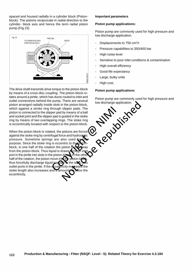
122 Production & Manufacturing : Fitter (NSQF- Level - 5): Related Theory for Exercise 4.3.184
spaced and housed radially in a cylinder block (Piston-block). The pistons reciprocate in radial direction to thecylinder- block axis and hence the term radial pistonpump.(Fig.15)
The drive shaft transmits drive torque to the piston-blockby means of a cross-disc coupling. The piston-block ro-tates around a pintle, which has ducts routed to inlet andoutlet connections behind the pump. There are severalpiston arranged radially inside slots in the piston-block,which against a stroke ring through slipper pads. Thepiston is connected to the slipper pad by means of a balland socket joint and the slipper pad is guided in the stokering by means of two overlapping rings. The stoke ringis eccentrically located with respect to the piston-block.
When the piston block is rotated, the pistons are forcedagainst the stoke ring by centrifugal force and hydrostaticpressure. Sometime springs are also used for thispurpose. Since the stoke ring is eccentric to the piston-block, in one half of the rotation the piston move awayfrom the piston-block. Thus liquid is drawn through inletport in the pintle into slots in the piston-block. In the otherhalf of the rotation, the piston move into the piston-block,thus forcefully discharge liquid trapped in the slots, intooutlet ports in the pintle. If the eccentricity increases thestoke length also increases and it amounts to twice theeccentricity.
Important parameters
Piston pump applications:
Piston pump are commonly used for high pressure andlow discharge application.
- Displacements to 750 cm3/r
- Pressure capabilities to 350/400 bar
- High noise level
- Sensitive to poor inlet conditions & contamination
- High overall efficiency
- Good life expectancy
- Large, bulky units
- High cost.
Piston pump applications
Piston pump are commonly used for high pressure andlow discharge application.
Copyrigh
t @ NIM
I
Not to be Republish
ed
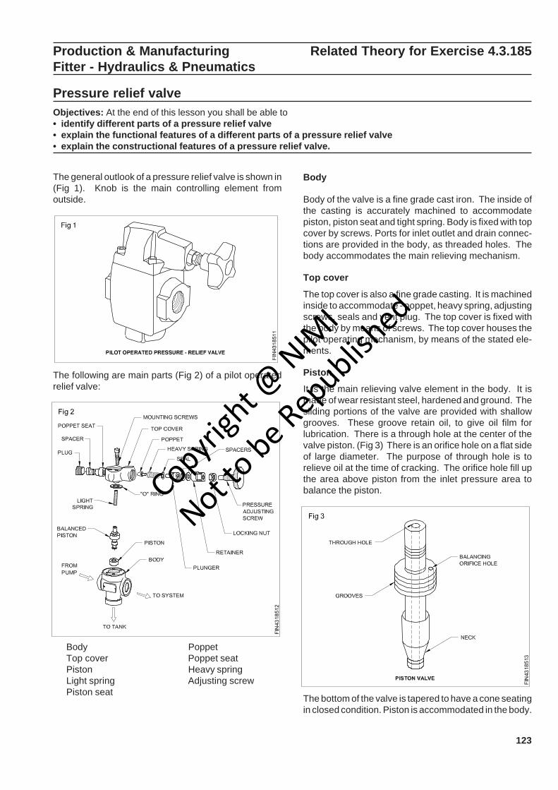
123
Production & Manufacturing Related Theory for Exercise 4.3.185Fitter - Hydraulics & Pneumatics
Pressure relief valveObjectives: At the end of this lesson you shall be able to• identify different parts of a pressure relief valve• explain the functional features of a different parts of a pressure relief valve• explain the constructional features of a pressure relief valve.
The general outlook of a pressure relief valve is shown in(Fig 1). Knob is the main controlling element fromoutside.
The following are main parts (Fig 2) of a pilot operatedrelief valve:
Body PoppetTop cover Poppet seatPiston Heavy springLight spring Adjusting screwPiston seat
Body
Body of the valve is a fine grade cast iron. The inside ofthe casting is accurately machined to accommodatepiston, piston seat and tight spring. Body is fixed with topcover by screws. Ports for inlet outlet and drain connec-tions are provided in the body, as threaded holes. Thebody accommodates the main relieving mechanism.
Top cover
The top cover is also a fine grade casting. It is machinedinside to accommodate - poppet, heavy spring, adjustingscrews, seals and vent plug. The top cover is fixed withthe body by means of screws. The top cover houses thepilot operating mechanism, by means of the stated ele-ments.
Piston
It is the main relieving valve element in the body. It ismade of wear resistant steel, hardened and ground. Thesliding portions of the valve are provided with shallowgrooves. These groove retain oil, to give oil film forlubrication. There is a through hole at the center of thevalve piston. (Fig 3) There is an orifice hole on a flat sideof large diameter. The purpose of through hole is torelieve oil at the time of cracking. The orifice hole fill upthe area above piston from the inlet pressure area tobalance the piston.
The bottom of the valve is tapered to have a cone seatingin closed condition. Piston is accommodated in the body.
Copyrigh
t @ NIM
I
Not to be Republish
ed
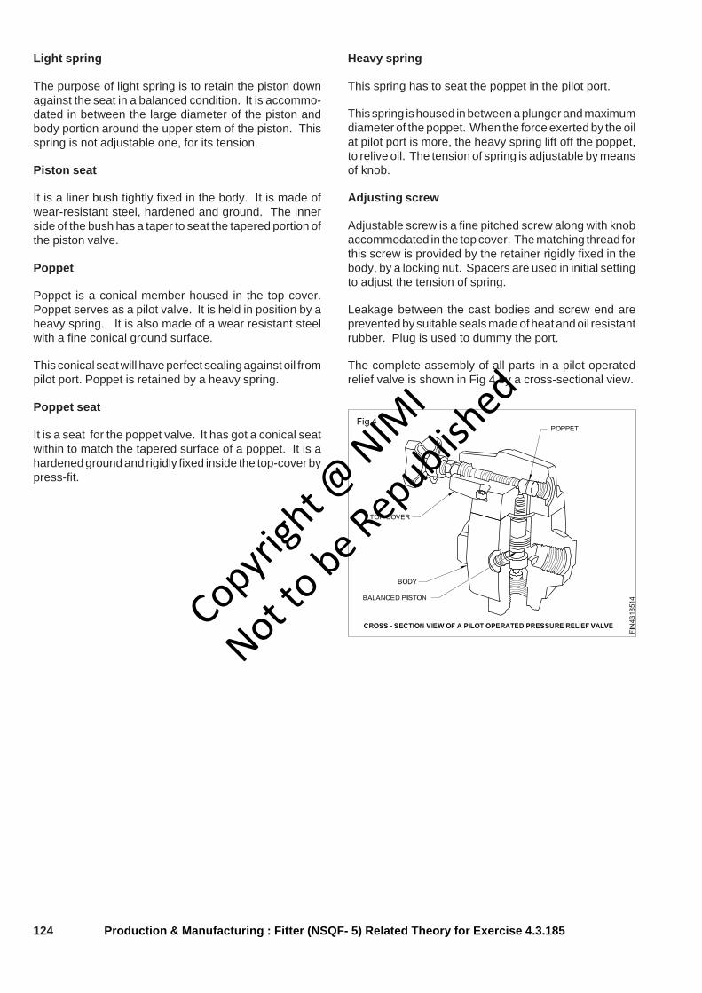
124
Light spring
The purpose of light spring is to retain the piston downagainst the seat in a balanced condition. It is accommo-dated in between the large diameter of the piston andbody portion around the upper stem of the piston. Thisspring is not adjustable one, for its tension.
Piston seat
It is a liner bush tightly fixed in the body. It is made ofwear-resistant steel, hardened and ground. The innerside of the bush has a taper to seat the tapered portion ofthe piston valve.
Poppet
Poppet is a conical member housed in the top cover.Poppet serves as a pilot valve. It is held in position by aheavy spring. It is also made of a wear resistant steelwith a fine conical ground surface.
This conical seat will have perfect sealing against oil frompilot port. Poppet is retained by a heavy spring.
Poppet seat
It is a seat for the poppet valve. It has got a conical seatwithin to match the tapered surface of a poppet. It is ahardened ground and rigidly fixed inside the top-cover bypress-fit.
Heavy spring
This spring has to seat the poppet in the pilot port.
This spring is housed in between a plunger and maximumdiameter of the poppet. When the force exerted by the oilat pilot port is more, the heavy spring lift off the poppet,to relive oil. The tension of spring is adjustable by meansof knob.
Adjusting screw
Adjustable screw is a fine pitched screw along with knobaccommodated in the top cover. The matching thread forthis screw is provided by the retainer rigidly fixed in thebody, by a locking nut. Spacers are used in initial settingto adjust the tension of spring.
Leakage between the cast bodies and screw end areprevented by suitable seals made of heat and oil resistantrubber. Plug is used to dummy the port.
The complete assembly of all parts in a pilot operatedrelief valve is shown in Fig 4 by a cross-sectional view.
Production & Manufacturing : Fitter (NSQF- 5) Related Theory for Exercise 4.3.185
Copyrigh
t @ NIM
I
Not to be Republish
ed
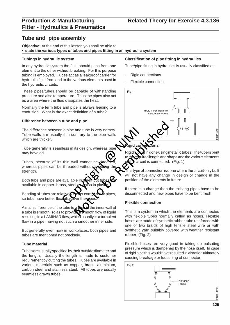
125
Production & Manufacturing Related Theory for Exercise 4.3.186Fitter - Hydraulics & Pneumatics
Tube and pipe assemblyObjective: At the end of this lesson you shall be able to• state the various types of tubes and pipes fitting in an hydraulic system
Tubings in hydraulic system
In any hydraulic system the fluid should pass from oneelement to the other without breaking. For this purposetubing is employed. Tubes act as a leakproof carrier forhydraulic fluid from and to the various elements used inthe hydraulic circuits.
These pipes/tubes should be capable of withstandingpressure and also temperature. Thus the pipes also actas a area where the fluid dissipates the heat.
Normally the term tube and pipe is always leading to aconfusion. What is the exact definition of a tube?
Difference between a tube and pipe
The difference between a pipe and tube is very narrow.Tube walls are usually thin contrary to the pipe wallswhich are thicker.
Tube generally is seamless in its design, whereas pipemay beveled.
Tubes, because of its thin wall cannot be threaded,whereas pipes can be threaded without affecting thestrength.
Both tube and pipe are available in steel, but tubes areavailable in copper, brass, steel and also in plastic.
Bending of tubes are relatively easier compared to pipes,so tube have better flexibility over the pipes.
A main difference of the tube to a pipe is the inner wall ofa tube is smooth, so as to provide a smooth flow of liquidresulting in a LAMINAR flow, which usually is a turbulentflow in a pipe, having not such a smoother inner side.
But generally even now in workplaces, both pipes andtubes are mentioned not precisely.
Tube material
Tubes are usually specified by their outside diameter andthe length. Usually the length is made to customerrequirement by cutting the tubes. Tubes are available invarious materials such as copper, brass, aluminium,carbon steel and stainless steel. All tubes are usuallyseamless drawn tubes.
Classification of pipe fitting in hydraulics
Tube/pipe fitting in hydraulics is usually classified as
- Rigid connections
- Flexible connection.
Rigid connections
Rigid tubing in done using metallic tubes. The tube is bentto the required length and shape and the various elementsof the circuit is connected. (Fig. 1)
This type of connection is done where the circuit only builtwill not have any change in design or change in theposition of the elements in future.
If there is a change then the existing pipes have to bedisconnected and new pipes have to be bent fresh.
Flexible connection
This is a system in which the elements are connectedwith flexible tubes normally called as hoses. Flexiblehoses are made of synthetic rubber tube reinforced withone or two braids of high tensile steel wire or withsynthetic yarn suitably covered with weather resistantrubber. (Fig. 2)
Flexible hoses are very good in taking up pulsatingpressure which is dampened by the hose itself. In caseof rigid pipe this would have resulted in vibration ultimatelycausing breakage or loosening of connector.
Copyrigh
t @ NIM
I
Not to be Republish
ed

126
Advantages of using hoses
- Insulates against shock noise and vibration
- Connects stationary parts
- Makes connection easier in congested space
- Makes good temporary connections
- Provides connections and disconnections which areto be frequently changed.
Types of flexible hoses
Flexible hoses again are available to cater various pres-sures and temperature ranges.
Hoses are usually classified according to the:
Type of construction
(a) Wire braided-single (Figs. 3 & 4) or double braid
Production & Manufacturing : Fitter (NSQF- Level - 5): Related Theory for Exercise 4.3.186
Type of pipe end fitting
Since hoses are used in various applications and has tomounted to suit a variety of connectors, it is also availablewith various end fitting. There are many type of end fittingavailable as required by customer. Some of them shownin the Fig. 5.
Specification of hoses
Flexible hoses are specified according to the followinginformations,
- Internal diameter
- Length between the two end connectors
- Pressure and temp withstanding capacity
- Type of end fitting.
All these can be readily referred from manufacturerscatalogue for the specific application. An example isgiven below.
dia.10 x 1000 x SAE100R2 x both ends female nuts.
(b) Synthetic yarn braid (Cotton, fibre, asbestos etc).
Normally the flexibility of synthetic yarn braided hosesare more flexible but the operating pressure is a limitation.
Whereas wire braided hoses because of steel wire usedis good in withstanding high pressures up to 300 cm2 butis not as flexible as synthetic yarn braided hose.
Pressure and temperature withstanding capacity
Hoses are used in hydraulic circuits and are subjected topressure from the oil flowing through it. So hoses areclassified according to its pressure withstanding capacityalso this is given by the specification standard SAEJ517as SAE100R1, SAE100R2 etc.
The number R1, R2 indicates the withstanding capacityin pressure and temperature and the construction. Thishas to be noted while selecting the hoses keeping in mindthe maximum pressure produced in the circuit underconstruction. For actual valves of pressure and tempera-ture the manufacturers catalogue has to be referred.
Connectors
Connectors are the elements which connects the tubeends to the body of the various hydraulic elements.Connectors also serve various other purposes like changein size of tube, change in direction of flow, restriction offlow etc. Connectors can be grouped according tovarious parameters.
Copyrigh
t @ NIM
I
Not to be Republish
ed

127Production & Manufacturing : Fitter (NSQF- Level - 5): Related Theory for Exercise 4.3.186
- According to the type of sealing design.
- According to the shape, size and purpose used for.
According to the type of sealing design
Flared fitting (Fig. 6)
In this, the pipe is flared and fitted to the suitable connec-tor.
'O' ring compression fitting (Fig 7)
In this type of ̀ O' ring seals the pipe outside diameter. Thesplit ring clamps the pipe in position.
Ferrule compression fitting (Fig 9)
In this, the ferrule is of a special design, ferrule bites intothe tube to form a permanent seal.
The selection of the right type of connector depend uponvarious factors like
- Working pressure of system
- Frequency of assembly and disassembly
- Vibration or shock level in circuit
- Working area.
According to the size, shape and purpose of use
Connectors are used to connect either a tube to the bodyof a hydraulic element or a tube end to another tube end.
To connect a hydraulic element to a tube end
The connector shown (Fig 11) has threads which isscrewed on to the body of the hydraulic element. On theother side a tube is fixed with proper sealing. This sealingis done by various methods as discussed in the previousexercise.
These connectors are available in various size accordingto the pipe it has to accommodate. The chart shows thepipe size and the threads on the connector.
Sleeve compression fitting (Fig 8)
In this the pipe is formed the neck seals the path for oilalong with the sleeve.
O' ring fitting (Fig. 10)
The pipe is welded with a ring with a flat face, this faceseals against a 'O' ring.
Various fitting have been illustrated, each of these fittingshave the corresponding connectors. The connection willbe perfect only when the connection is made accordingto the manufacturers instructions.
Copyrigh
t @ NIM
I
Not to be Republish
ed

128 Production & Manufacturing : Fitter (NSQF- Level - 5): Related Theory for Exercise 4.3.186
The various types of connectors in this category to takecare of the flow direction of fluid as follows
Straight connector (Fig 12)
To connect tube perpendicular to the body.
Elbow connector (Fig 13)
To connect the tube end parallel to the body of thehydraulic elements.
Flange connection (Fig 15)
Big size valves do not have threaded ports. They onlyhave a hole as a port. In these case a flange is mountedon the body and the connector is mounted on the flange.This is also called as flush mounting.
Plug (Fig 16)
A plug is used to block any port of the hydraulic element.
To connect a tube end to another tube end
'T' connector (Fig 17)
Used to connect three pipe ends at a junction.
Banjo connector (Fig 14)
Banjo connector is similar to a elbow, but has the flexibilityto turn 360 degree with the port axis. This helps in easypositioning of the pipe, with hydraulic elements.
4 way connector (Fig 18)
Connect 4 pipe ends at a junction.
Pipe outsidedia British standard Metricpipe thread (BSP) Fine thread
6 R 1/4" M22 x 1.5
8 R 1/4" M14 x 1.5
10 R 3/8" M16 x 1.5
12 R 3/8" M18 x 1.5
14 R 1/2" M20 x 1.5
16 R 1/2" M22 x 1.5
20 R 3/4" M27 x 2
25 R 1 M33 x 2
30 R 11/4" M42 x 2
38 R 11/2" M48 x 2
Copyrigh
t @ NIM
I
Not to be Republish
ed
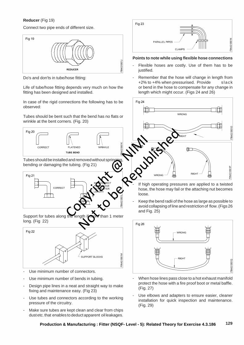
129Production & Manufacturing : Fitter (NSQF- Level - 5): Related Theory for Exercise 4.3.186
Reducer (Fig 19)
Connect two pipe ends of different size.
Support for tubes along the length if more than 1 meterlong. (Fig 22)
Do's and don'ts in tube/hose fitting:
Life of tube/hose fitting depends very much on how thefitting has been designed and installed.
In case of the rigid connections the following has to beobserved:
Tubes should be bent such that the bend has no flats orwrinkle at the bent corners. (Fig. 20)
Tubes should be installed and removed without springing,bending or damaging the tubing. (Fig 21)
- Use minimum number of connectors.
- Use minimum number of bends in tubing.
- Design pipe lines in a neat and straight way to makefixing and maintenance easy. (Fig 23)
- Use tubes and connectors according to the workingpressure of the circuitry.
- Make sure tubes are kept clean and clear from chipsdust etc. that enables to deduct apparent oil leakages.
Points to note while using flexible hose connections
- Flexible hoses are costly. Use of them has to bejustified.
- Remember that the hose will change in length from+2% to +4% when pressurised. Provide s lackor bend in the hose to compensate for any change inlength which might occur. (Figs 24 and 26)
- If high operating pressures are applied to a twistedhose, the hose may fail or the attaching nut becomesloose.
- Keep the bend radii of the hose as large as possible toavoid collapsing of line and restriction of flow. (Figs 26and Fig. 25)
- When hose lines pass close to a hot exhaust manifoldprotect the hose with a fire proof boot or metal baffle.(Fig. 27)
- Use elbows and adapters to ensure easier, cleanerinstallation for quick inspection and maintenance.(Fig. 29)
Copyrigh
t @ NIM
I
Not to be Republish
ed
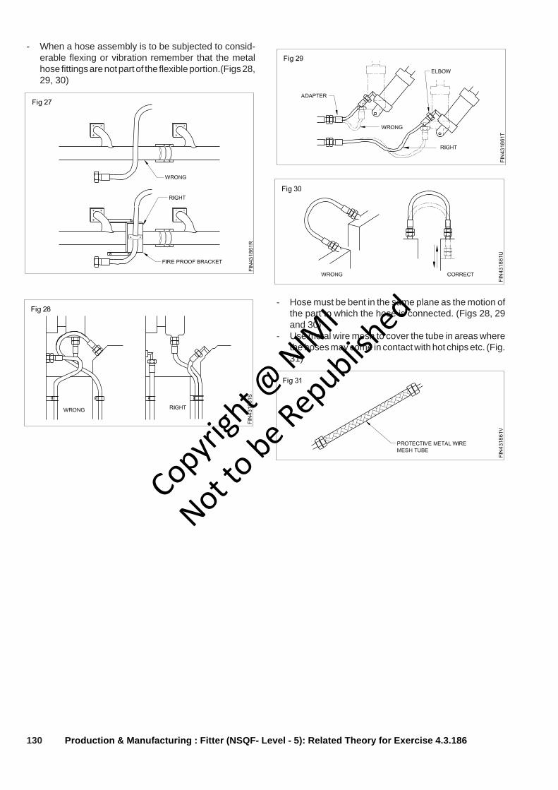
130 Production & Manufacturing : Fitter (NSQF- Level - 5): Related Theory for Exercise 4.3.186
- Hose must be bent in the same plane as the motion ofthe part to which the hose is connected. (Figs 28, 29and 30)
- Use metal wire mesh to cover the tube in areas wherethe hoses may come in contact with hot chips etc. (Fig.31)
- When a hose assembly is to be subjected to consid-erable flexing or vibration remember that the metalhose fittings are not part of the flexible portion.(Figs 28,29, 30)
Copyrigh
t @ NIM
I
Not to be Republish
ed
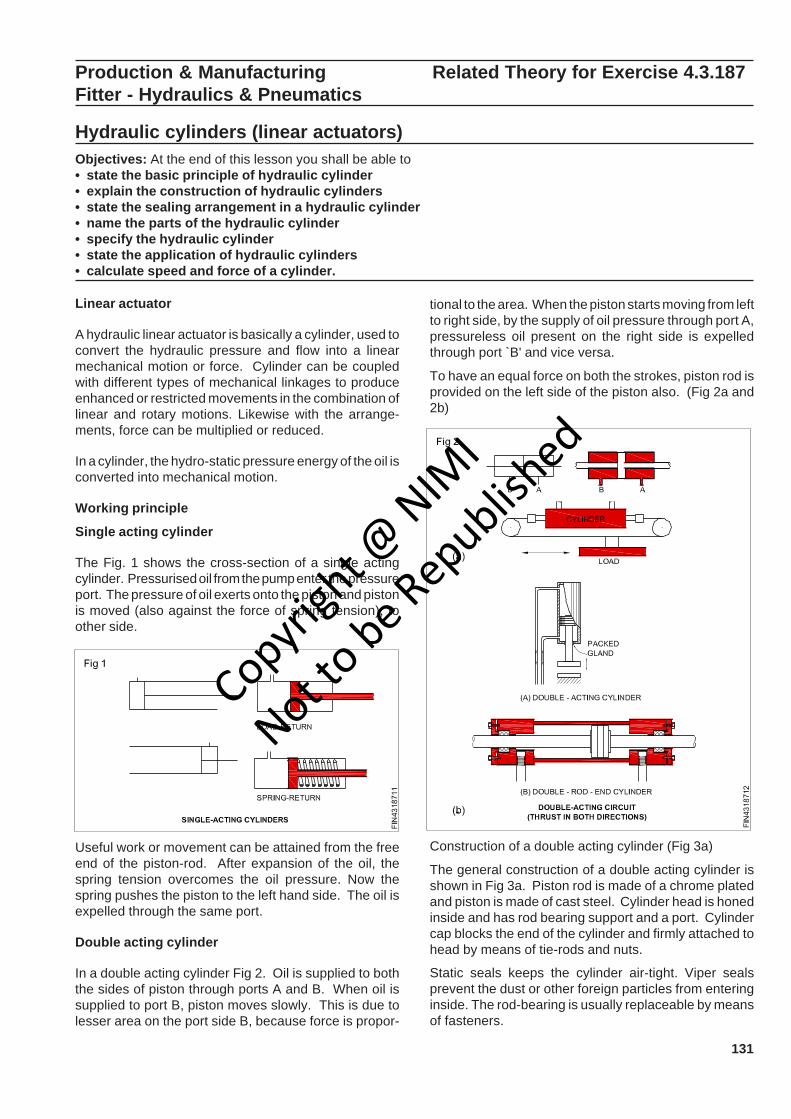
131
Useful work or movement can be attained from the freeend of the piston-rod. After expansion of the oil, thespring tension overcomes the oil pressure. Now thespring pushes the piston to the left hand side. The oil isexpelled through the same port.
Double acting cylinder
In a double acting cylinder Fig 2. Oil is supplied to boththe sides of piston through ports A and B. When oil issupplied to port B, piston moves slowly. This is due tolesser area on the port side B, because force is propor-
tional to the area. When the piston starts moving from leftto right side, by the supply of oil pressure through port A,pressureless oil present on the right side is expelledthrough port `B' and vice versa.
To have an equal force on both the strokes, piston rod isprovided on the left side of the piston also. (Fig 2a and2b)
Production & Manufacturing Related Theory for Exercise 4.3.187Fitter - Hydraulics & Pneumatics
Hydraulic cylinders (linear actuators)Objectives: At the end of this lesson you shall be able to• state the basic principle of hydraulic cylinder• explain the construction of hydraulic cylinders• state the sealing arrangement in a hydraulic cylinder• name the parts of the hydraulic cylinder• specify the hydraulic cylinder• state the application of hydraulic cylinders• calculate speed and force of a cylinder.
Linear actuator
A hydraulic linear actuator is basically a cylinder, used toconvert the hydraulic pressure and flow into a linearmechanical motion or force. Cylinder can be coupledwith different types of mechanical linkages to produceenhanced or restricted movements in the combination oflinear and rotary motions. Likewise with the arrange-ments, force can be multiplied or reduced.
In a cylinder, the hydro-static pressure energy of the oil isconverted into mechanical motion.
Working principle
Single acting cylinder
The Fig. 1 shows the cross-section of a single actingcylinder. Pressurised oil from the pump enter the pressureport. The pressure of oil exerts onto the piston and pistonis moved (also against the force of spring tension), toother side.
Construction of a double acting cylinder (Fig 3a)
The general construction of a double acting cylinder isshown in Fig 3a. Piston rod is made of a chrome platedand piston is made of cast steel. Cylinder head is honedinside and has rod bearing support and a port. Cylindercap blocks the end of the cylinder and firmly attached tohead by means of tie-rods and nuts.
Static seals keeps the cylinder air-tight. Viper sealsprevent the dust or other foreign particles from enteringinside. The rod-bearing is usually replaceable by meansof fasteners.
Copyrigh
t @ NIM
I
Not to be Republish
ed
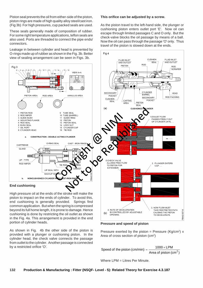
132
Piston seal prevents the oil from either-side of the piston,piston rings are made of high quality alloy steel/cast iron.(Fig 3b) For high pressures, cup packed seals are used.
These seals generally made of composition of rubber.For some right temperature applications, teflon seals arealso used. Ports are threaded to connect the pipe ends/connectors.
Leakage in between cylinder and head is prevented byO-rings made up of rubber as shown in the Fig. 3b. Betterview of sealing arrangement can be seen in Figs. 3b.
Production & Manufacturing : Fitter (NSQF- Level - 5): Related Theory for Exercise 4.3.187
End cushioning
High pressure oil at the ends of the stroke will make thepiston to impact on the ends of cylinder. To avoid this,end cushioning is generally provided. Springs findcommon application. But when the spring is compressedbeyond its full home length, it is prone to damage. Hencecushioning is done by restricting the oil outlet as shownin the Fig. 4a. This arrangement is provided in the endportion of cylinder heads.
As shown in Fig. 4b the other side of the piston isprovided with a plunger or cushioning piston. In thecylinder head, the check valve connects the passagefrom outlet to the cylinder. Another passage is connectedby a restricted orifice 'O'.
This orifice can be adjusted by a screw.
As the piston travel to the left-hand side, the plunger orcushioning piston enters outlet port 'E'. Now oil canescape through limited passages C and O only. But thecheck-valve blocks the oil passage by means of a ball.Now the oil can pass through the passage 'O' only. Thustravel of the piston is slowed down at the ends.
Pressure and speed of piston
Pressure exerted by the piston = Pressure (Kg/cm2) xArea of cross section of piston (cm2)
)(cm piston of AreaLPM 1000(cm/min) piston the of Speed 2
×=
Where LPM = Litres Per Minute.
Copyrigh
t @ NIM
I
Not to be Republish
ed

133Production & Manufacturing : Fitter (NSQF- Level - 5): Related Theory for Exercise 4.3.187
Symbol
The symbols for hydraulic cylinders resembles the sym-bols of pneumatic cylinders. The symbols for commonlyused cylinders are given in Fig 5.
Classification of cylinders
Two basic types of cylinders are
- Single acting cylinders
- Double acting cylinders
Single acting cylinders are further classified into
- Plunge type
- Piston type
- Ram type
- Telescopic type.
Double acting cylinders can be further classified into
- Single piston rod type
- Double sided piston rod
- D.A. cylinder with end cushioning
- Telescopic type
- Pressure intensifier
- Tandem cylinder.
Ram
It is the simplest linear actuator as shown in Fig 6. It hasonly one chamber for oil. They are usually mountedvertical and ram descends down by its self weight. Ramsare practically suitable for long strokes and used inelevators jacks and automobile.
Since the diameter of the Ram is throughout and there isno piston rod, if the Ram has to descends down at a fasterrate than gravity, oil has to be supplied to the top as in thecase of a double acting cylinder. (Fig 7)
However, the diameter of the Ram can be reduced only toa little extent to have piston rod.
The application of a double sided or dual Ram in turningthe rudder of a ship is shown in Fig 8.
Mountings of cylinders
Cylinders are mounted on different points to have adesirable movement space limitations, severity of load,direction of actuation etc. Fig 9 shows the possible meth-ods of mounting a hydraulic cylinder.
Copyrigh
t @ NIM
I
Not to be Republish
ed
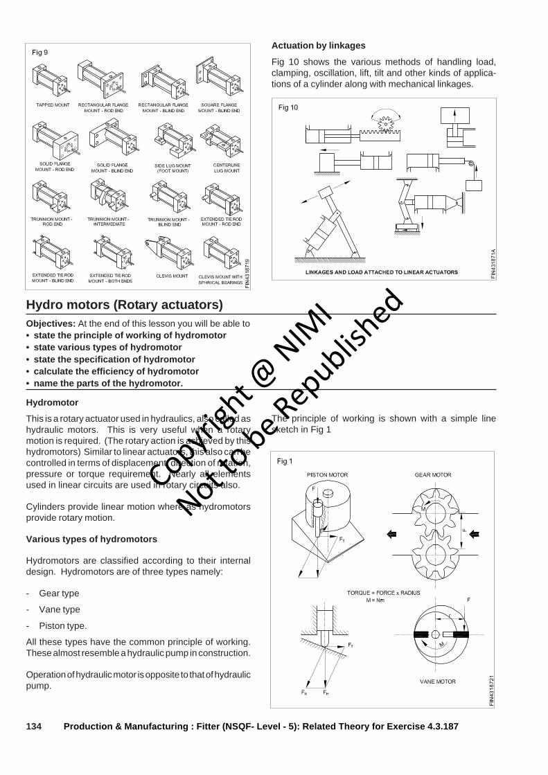
134 Production & Manufacturing : Fitter (NSQF- Level - 5): Related Theory for Exercise 4.3.187
Actuation by linkages
Fig 10 shows the various methods of handling load,clamping, oscillation, lift, tilt and other kinds of applica-tions of a cylinder along with mechanical linkages.
Hydro motors (Rotary actuators)Objectives: At the end of this lesson you will be able to• state the principle of working of hydromotor• state various types of hydromotor• state the specification of hydromotor• calculate the efficiency of hydromotor• name the parts of the hydromotor.
Hydromotor
This is a rotary actuator used in hydraulics, also called ashydraulic motors. This is very useful when a rotarymotion is required. (The rotary action is achieved by thishydromotors) Similar to linear actuators, this also can becontrolled in terms of displacement, direction of rotation,pressure or torque requirement. Nearly all elementsused in linear circuits are used in rotary circuits also.
Cylinders provide linear motion where as hydromotorsprovide rotary motion.
Various types of hydromotors
Hydromotors are classified according to their internaldesign. Hydromotors are of three types namely:
- Gear type
- Vane type
- Piston type.
All these types have the common principle of working.These almost resemble a hydraulic pump in construction.
Operation of hydraulic motor is opposite to that of hydraulicpump.
The principle of working is shown with a simple linesketch in Fig 1
Copyrigh
t @ NIM
I
Not to be Republish
ed
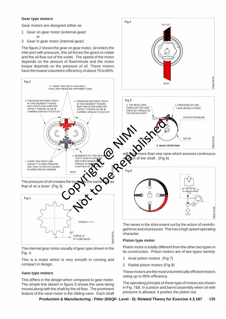
135Production & Manufacturing : Fitter (NSQF- Level - 5): Related Theory for Exercise 4.3.187
Gear type motors
Gear motors are designed either as
1 Gear on gear motor (external gear) or2 Gear in gear motor (internal gear).
The figure 2 shows the gear on gear motor, oil enters theinlet port with pressure, this oil forces the gears to rotateand the oil flow out of the outlet. The speed of the motordepends on the amount of flow/minute and the motortorque depends on the pressure of oil. These motorshave the lowest volumetric efficiency of about 70 to 80%.
The pressure of oil creates the torque in the same way asthat of on a lever. (Fig 3)
The internal gear motor usually of gear type shown in theFig. 4.
This is a motor which is very smooth in running andcompact in design.
Vane type motors
This differs in the design when compared to gear motor.The simple line sketch in figure 5 shows the vane beingmoved along with the shaft by the oil flow. The prominentfeature of the vane motor is the sliding vane. Each shaft
will have more than one vane which ensures continuousrotation of the shaft. (Fig 6)
The vanes in the slots extent out by the action of centrifu-gal force and oil pressure. This has a high speed operatingcharacter.
Piston type motor
Piston motor is totally different from the other two types inits construction. Piston motors are of two types namely
1 Axial piston motors (Fig 7)
2 Radial piston motors (Fig 8)
These motors are the most volumetrically efficient motorsrating up to 95% efficiency.
The operating principle of these type of motors are shownin Fig 7&8. In a piston and barrel assembly when oil withpressure is allowed, it pushes the piston out.
Copyrigh
t @ NIM
I
Not to be Republish
ed
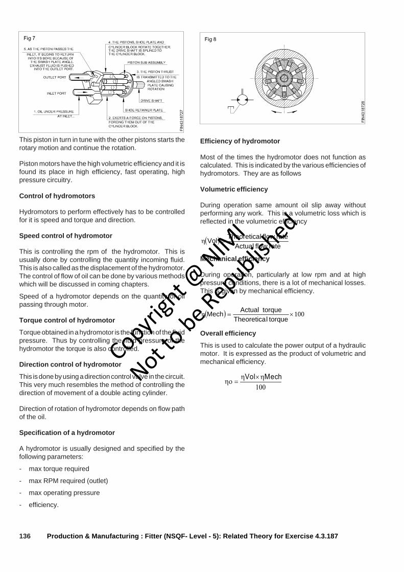
136 Production & Manufacturing : Fitter (NSQF- Level - 5): Related Theory for Exercise 4.3.187
This piston in turn in tune with the other pistons starts therotary motion and continue the rotation.
Piston motors have the high volumetric efficiency and it isfound its place in high efficiency, fast operating, highpressure circuitry.
Control of hydromotors
Hydromotors to perform effectively has to be controlledfor it is speed and torque and direction.
Speed control of hydromotor
This is controlling the rpm of the hydromotor. This isusually done by controlling the quantity incoming fluid.This is also called as the displacement of the hydromotor.The control of flow of oil can be done by various methodswhich will be discussed in coming chapters.
Speed of a hydromotor depends on the quantity of oilpassing through motor.
Torque control of hydromotor
Torque obtained in a hydromotor is the function of the fluidpressure. Thus by controlling the fluid pressure of thehydromotor the torque is also controlled.
Direction control of hydromotor
This is done by using a direction control valve in the circuit.This very much resembles the method of controlling thedirection of movement of a double acting cylinder.
Direction of rotation of hydromotor depends on flow pathof the oil.
Specification of a hydromotor
A hydromotor is usually designed and specified by thefollowing parameters:
- max torque required
- max RPM required (outlet)
- max operating pressure
- efficiency.
Efficiency of hydromotor
Most of the times the hydromotor does not function ascalculated. This is indicated by the various efficiencies ofhydromotors. They are as follows
Volumetric efficiency
During operation same amount oil slip away withoutperforming any work. This is a volumetric loss which isreflected in the volumetric efficiency
( )rate flow Actual
rateflow lTheoreticaVol =η
Mechanical efficiency
During operation, particularly at low rpm and at highpressure conditions, there is a lot of mechanical losses.This is given by mechanical efficiency.
( ) 100×=ηtorque lTheoretica
torque ActualMech
Overall efficiency
This is used to calculate the power output of a hydraulicmotor. It is expressed as the product of volumetric andmechanical efficiency.
100MechVol η×η
=ηο
Copyrigh
t @ NIM
I
Not to be Republish
ed
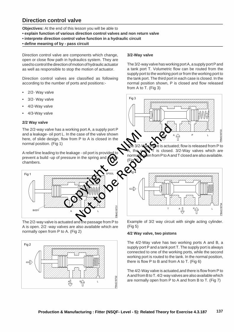
137Production & Manufacturing : Fitter (NSQF- Level - 5): Related Theory for Exercise 4.3.187
Direction control valveObjectives: At the end of this lesson you will be able to• explain function of various direction control valves and non return valve• interprete direction control valve function in a hydraulic circuit• define meaning of by - pass circuit
Direction control valve are components which change,open or close flow path in hydraulics system. They areused to control the direction of motion of hydraulic actuatoras well as responsible to stop the motion of actuator.
Direction control valves are classified as followingaccording to the number of ports and positions:-
• 2/2- Way valve
• 3/2- Way valve
• 4/2-Way valve
• 4/3-Way valve
2/2 Way valve
The 2/2-way valve has a working port A, a supply port Pand a leakage- oil port L. In the case of the valve shownhere, of slide design, flow from P to A is closed in thenormal position. (Fig 1)
A relief line leading to the leakage - oil port is provided toprevent a build -up of pressure in the spring and pistonchambers.
The 2/2-way valve is actuated and the passage from P toA is open. 2/2 -way valves are also available which arenormally open from P to A. (Fig 2)
3/2-Way valve
The 3/2-way valve has working port A, a supply port P anda tank port T. Volumetric flow can be routed from thesupply port to the working port or from the working port tothe tank port. The third port in each case is closed. In thenormal position shown, P is closed and flow releasedfrom A to T. (Fig 3)
The 3/2-Way valve is actuated; flow is released from P toA, the outlet T is closed. 3/2-Way valves which arenormally open from P to A and T closed are also available.(Fig 4)
Example of 3/2 way circuit with single acting cylinder.(Fig 5)
4/2 Way valve, two pistons
The 4/2-Way valve has two working ports A and B, asupply port P and a tank port T. The supply port is alwaysconnected to one of the working ports, while the secondworking port is routed to the tank. In the normal position,there is flow P to B and from A to T. (Fig 6)
The 4/2-Way valve is actuated,and there is flow from P toA and from B to T. 4/2-way valves are also available whichare normally open from P to A and from B to T. (Fig 7)
Copyrigh
t @ NIM
I
Not to be Republish
ed
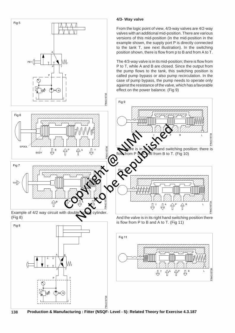
138 Production & Manufacturing : Fitter (NSQF- Level - 5): Related Theory for Exercise 4.3.187
Example of 4/2 way circuit with double acting cylinder.(Fig 8)
4/3- Way valve
From the logic point of view, 4/3-way valves are 4/2-wayvalves with an additional mid-position. There are variousversions of this mid-position (in the mid-position in theexample shown, the supply port P is directly connectedto the tank T, see next illustration). In the switchingposition shown, there is flow from p to B and from A to T.
The 4/3-way valve is in its mid-position; there is flow fromP to T, while A and B are closed. Since the output fromthe pump flows to the tank, this switching position iscalled pump bypass or also pump recirculation. In thecase of pump bypass, the pump needs to operate onlyagainst the resistance of the valve, which has a favorableeffect on the power balance. (Fig 9)
The valve is in its left-hand switching position; there isflow from P to A and from B to T. (Fig 10)
And the valve is in its right hand switching position thereis flow from P to B and A to T. (Fig 11)
Copyrigh
t @ NIM
I
Not to be Republish
ed
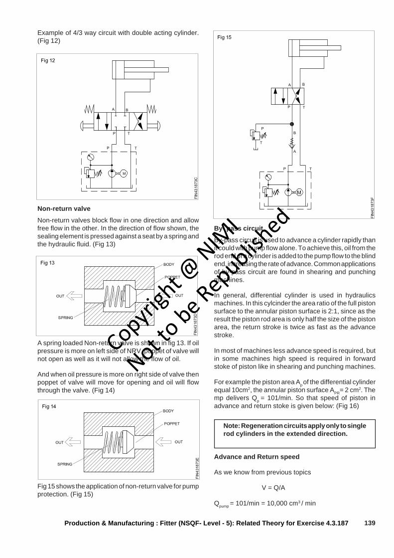
139Production & Manufacturing : Fitter (NSQF- Level - 5): Related Theory for Exercise 4.3.187
Example of 4/3 way circuit with double acting cylinder.(Fig 12)
Non-return valve
Non-return valves block flow in one direction and allowfree flow in the other. In the direction of flow shown, thesealing element is pressed against a seat by a spring andthe hydraulic fluid. (Fig 13)
A spring loaded Non-return valve is shown in fig 13. If oilpressure is more on left side of NRV, poppet of valve willnot open as well as it will not allow the flow of oil.
And when oil pressure is more on right side of valve thenpoppet of valve will move for opening and oil will flowthrough the valve. (Fig 14)
Fig 15 shows the application of non-return valve for pumpprotection. (Fig 15)
By- pass circuit
By-pass circuit is used to advance a cylinder rapidly thanit could with pump flow alone. To achieve this, oil from therod end of a cylinder is added to the pump flow to the blindend, increasing the rate of advance. Common applicationsof by-pass circuit are found in shearing and punchingmachines.
In general, differential cylinder is used in hydraulicsmachines. In this cylcinder the area ratio of the full pistonsurface to the annular piston surface is 2:1, since as theresult the piston rod area is only half the size of the pistonarea, the return stroke is twice as fast as the advancestroke.
In most of machines less advance speed is required, butin some machines high speed is required in forwardstoke of piston like in shearing and punching machines.
For example the piston area Ap of the differential cylinderequal 10cm2, the annular piston surface APR= 2 cm2. Themp delivers Qp = 101/min. So that speed of piston inadvance and return stoke is given below: (Fig 16)
Note: Regeneration circuits apply only to singlerod cylinders in the extended direction.
Advance and Return speed
As we know from previous topics
V = Q/A
Qpump = 101/min = 10,000 cm3 / min
Copyrigh
t @ NIM
I
Not to be Republish
ed

140 Production & Manufacturing : Fitter (NSQF- Level - 5): Related Theory for Exercise 4.3.187
Advance speed
VADV = 10,000 cm3 / 10 cm2 min
VADV = 10,00 cm/ min
VADV = 10m /min
Return speed
VRET = 10,000 cm3 /2 cm2 min
VRET = 5000 cm / min
VRET = 50cm / min
From this result it can be seen that the area ratio has adirect effect on speed and time.
For getting more forward speed in differential cylinderwe can utilize the oil of rod side of cylinder intopiston side, such a circuit is known as regenerationcircuit or bypass circuit.
By- pass circuit (Fig 17)
Qp = pump delivery
QR = return delivery from piston rod area
Qtotal = Pump delivery + return delivery
It means oil which is going inside the piston end ofcylinder is more than pump flow and more flow meansmore speed of actuator.
When the rod ends port is directly connected to the pistonend port than during forward stoke of piston, rod end oil isrecirculated and added on piston end of cylinder.
Below circuit is the example of a regeneration circuit alongwith 3/2 way valve. In normal condition (without actuation)oil is only going on the rod side of cylinder and from thepiston end of cylinder oil is coming back into tank so thatthe piston remain in retracted position. (Fig 18)
In actuated condition of valve, A port and B port areconnected to P port, means pump flow is added with flowof rod side.
Qtotal = Pump delivery + return delivery
More flow is going inside the cylinder in actuated conditionso that speed becomes very high (Fig 19)
Copyrigh
t @ NIM
I
Not to be Republish
ed

141
Production & Manufacturing Related Theory for Exercise 4.3.188Fitter - Hydraulics & Pneumatics
Flow control valveObjectives: At the end of this lesson you shall be able to• state the need for flow control in a hydraulic circuit• state the principle of operation of flow control valve• draw different symbols of flow control valves and state the functions from the symbols.
The whole purpose of a flow control valve is to vary thespeed of an actuating cylinder or motor. This is possibleby controlling the flow rate of the fluid.
A flow control valve accomplish any one or more of thefollowing control functions:
- To limit the maximum speed of the linear or rotaryactuators
⎟⎟⎠
⎞⎜⎜⎝
⎛= speedpiston
areapistonrateflow
- To limit the maximum pressure available to branchcircuits by limiting the flow. (power = flow rate xpressure)
- Proportionately divide or regulate the flow from pumpto various branch circuits.
Principle of operation
As shown in Fig 1, the oil under pressure P1 enters thevalve at A and flows through a restricted section, into theoutlet B. While passing through the restricted passage, oilattains heat due to the friction. Thus the hydraulic energyin terms of pressure is converted into heat energy. Theloss of energy is the result of drop in pressure.
The difference between the two pressure is called pres-sure drop.
p = p1 - p2
The volume of flow (litres/min) is mainly dependent onthe:
- Cross-section of restriction (Fig 2)
- Shape and length of orifice
- Pressure difference p
- Viscosity of the hydraulic oil.
The basic principle can be understood from Fig 3.
Symbol
As a general norm, the basic envelop is represented by asquare to denote a valve. The flow line passes pastthrough the square. The flow restrictions are denoted bycurvatures above and below the flow line.
The arrow mark stroked across the curvatures meansthat, the flow restriction is adjustable. Sometimes full flowis to be ensured in the reverse direction. This can bemade possible by connecting a check valve (non-returnvalve) in a right direction across the flow control valve. Asindicated in Fig 3, in the forward direction, oil flows frompressure port (P) to working port (A). In the reversedirection oil flows from port A to port P, by pushing thespring loaded valve.
In case, if the return oil is to flow to the tank, the pressureport P will become tank port `T' by means of a directioncontrol valve in the circuit.
In Fig 4 symbols are given in combined operations. Fig 4Ashows a control valve is adjustable and compensation isgiven for pressure as well as temperature. Fig 4B showa symbol for fixed type orifice and reducing valve-typecompensation. Fig 4C indicates an adjustable orifice andrelief valve type compensation.
The shape of on orifice and restrictor are shown in Fig 5.Restrictor is less sensitive to temperature variation.
The flow characters are changed in the following aspects
- The velocity past the valve.-- The pressure at the outlet of the valve is less than that
of the inlet.
Copyrigh
t @ NIM
I
Not to be Republish
ed
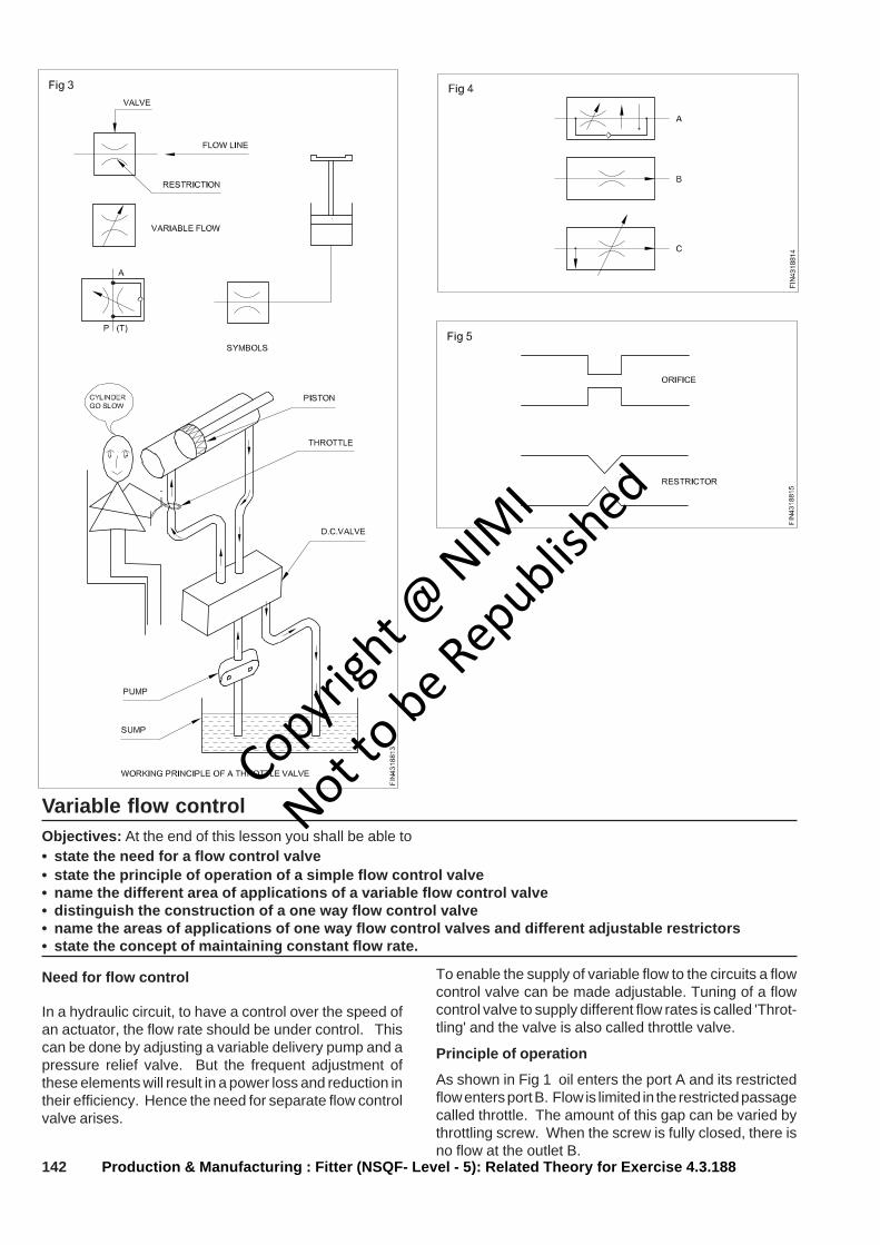
142
Variable flow controlObjectives: At the end of this lesson you shall be able to• state the need for a flow control valve• state the principle of operation of a simple flow control valve• name the different area of applications of a variable flow control valve• distinguish the construction of a one way flow control valve• name the areas of applications of one way flow control valves and different adjustable restrictors• state the concept of maintaining constant flow rate.
Need for flow control
In a hydraulic circuit, to have a control over the speed ofan actuator, the flow rate should be under control. Thiscan be done by adjusting a variable delivery pump and apressure relief valve. But the frequent adjustment ofthese elements will result in a power loss and reduction intheir efficiency. Hence the need for separate flow controlvalve arises.
To enable the supply of variable flow to the circuits a flowcontrol valve can be made adjustable. Tuning of a flowcontrol valve to supply different flow rates is called 'Throt-tling' and the valve is also called throttle valve.
Principle of operation
As shown in Fig 1 oil enters the port A and its restrictedflow enters port B. Flow is limited in the restricted passagecalled throttle. The amount of this gap can be varied bythrottling screw. When the screw is fully closed, there isno flow at the outlet B.
Production & Manufacturing : Fitter (NSQF- Level - 5): Related Theory for Exercise 4.3.188
Copyrigh
t @ NIM
I
Not to be Republish
ed
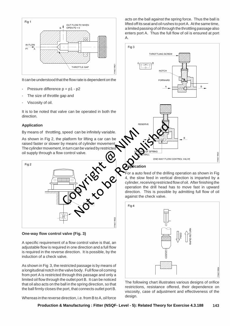
143
It can be understood that the flow rate is dependent on the
- Pressure difference p = p1 - p2
- The size of throttle gap and
- Viscosity of oil.
It is to be noted that valve can be operated in both thedirection.
Application
By means of throttling, speed can be infinitely variable.
As shown in Fig 2, the platform for lifting a car can beraised faster or slower by means of cylinder movement.The cylinder movement, in turn can be varied by restrictedoil supply through a flow control valve.
Application
For a auto feed of the drilling operation as shown in Fig4, the slow feed in vertical direction is imparted by acylinder, receiving restricted flow of oil. After finishing theoperation the drill head has to move fast in upwarddirection. This is possible by admitting full flow of oilagainst the check valve.
Production & Manufacturing : Fitter (NSQF- Level - 5): Related Theory for Exercise 4.3.188
One-way flow control valve (Fig. 3)
A specific requirement of a flow control valve is that, anadjustable flow is required in one direction and a full flowis required in the reverse direction. It is possible, by theinduction of a check valve.
As shown in Fig 3, the restricted passage is by means ofa longitudinal notch in the valve body. Full flow oil comingfrom port A is restricted through this passage and only alimited oil flow through the outlet port B. It can be noticedthat oil also acts on the ball in the spring direction, so thatthe ball firmly closes the port, that connects outlet port B.
Whereas in the reverse direction, i.e. from B to A, oil force
acts on the ball against the spring force. Thus the ball islifted off its seat and oil rushes to port A. At the same time,a limited passing of oil through the throttling passage alsoenters port A. Thus the full flow of oil is ensured at portA.
The following chart illustrates various designs of orificerestrictions, resistance offered, their dependence onviscosity, case of adjustment and effectiveness of thedesign.
Copyrigh
t @ NIM
I
Not to be Republish
ed
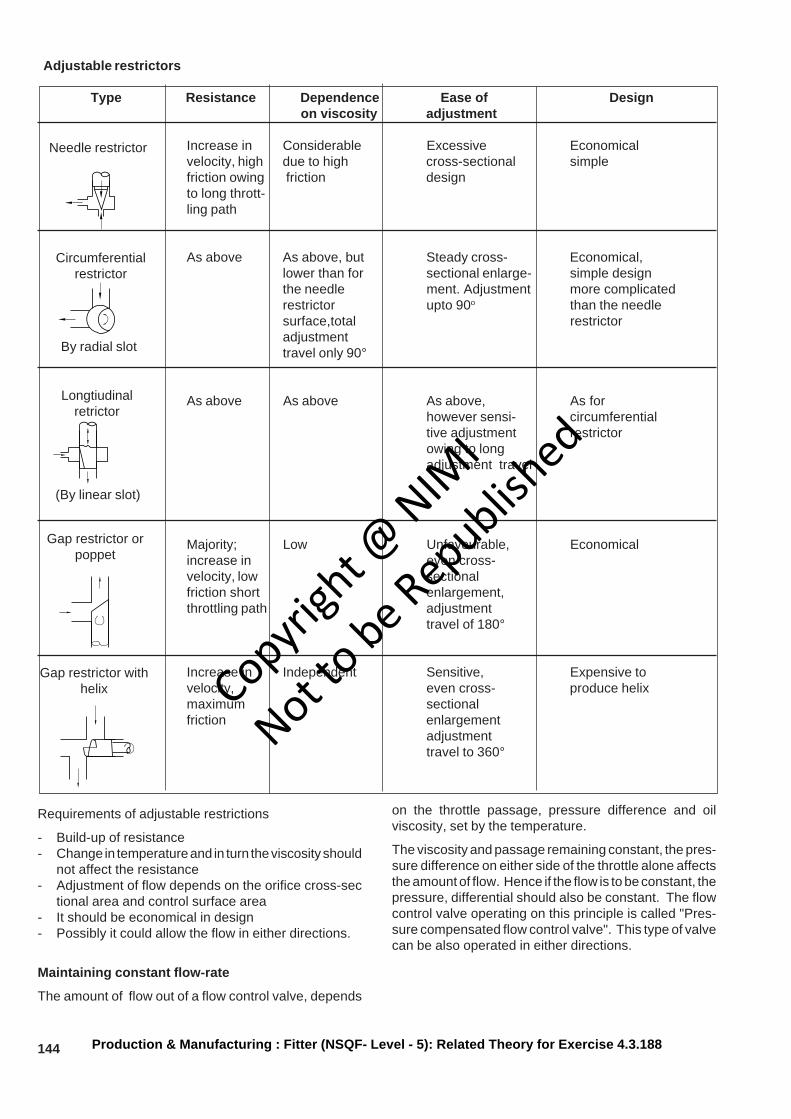
144
Adjustable restrictors
Type Resistance Dependence Ease of Design on viscosity adjustment
Increase in Considerable Excessive Economicalvelocity, high due to high cross-sectional simplefriction owing friction designto long thrott-ling path
As above As above, but Steady cross- Economical,lower than for sectional enlarge- simple designthe needle ment. Adjustment more complicatedrestrictor upto 90o than the needlesurface,total restrictoradjustmenttravel only 90°
As above As above As above, As forhowever sensi- circumferentialtive adjustment restrictorowing to longadjustment travel
Majority; Low Unfavourable, Economicalincrease in even cross-velocity, low sectionalfriction short enlargement,throttling path adjustment
travel of 180°
Increase in Independent Sensitive, Expensive tovelocity, even cross- produce helixmaximum sectionalfriction enlargement
adjustmenttravel to 360°
Requirements of adjustable restrictions
- Build-up of resistance- Change in temperature and in turn the viscosity should
not affect the resistance- Adjustment of flow depends on the orifice cross-sec
tional area and control surface area- It should be economical in design- Possibly it could allow the flow in either directions.
Maintaining constant flow-rate
The amount of flow out of a flow control valve, depends
on the throttle passage, pressure difference and oilviscosity, set by the temperature.
The viscosity and passage remaining constant, the pres-sure difference on either side of the throttle alone affectsthe amount of flow. Hence if the flow is to be constant, thepressure, differential should also be constant. The flowcontrol valve operating on this principle is called "Pres-sure compensated flow control valve". This type of valvecan be also operated in either directions.
Production & Manufacturing : Fitter (NSQF- Level - 5): Related Theory for Exercise 4.3.188
Needle restrictor
Circumferentialrestrictor
By radial slot
Longtiudinalretrictor
(By linear slot)
Gap restrictor orpoppet
Gap restrictor withhelix Copyri
ght @
NIMI
Not to be Republish
ed
145Production & Manufacturing : Fitter (NSQF- Level - 5): Related Theory for Exercise 4.3.188
Common maintenance procedures for hydraulic and pneumatics control systemObjectives: At the end of this lesson you will be able to• plan hydraulics and pneumatic maintenance practices• select proper practices of hydraulics and pneumatics maintenance.
Key concepts
• Trouble shooting, done in a logical manner, can solvemost hydraulic and pneumatic system problems.
• Safety should be the first consideration when troubleshooting.
• Inspect the equipment and question the operator tohelp solve problems in hydraulic and pneumaticsystems.
Safety Precautions
Hydraulic systems operate under very high pressures.Shut the system down and relieve system pressurebefore opening any part of the system that is underpressure. Do not allow spray from any high pressure leakto contact any part of the body, as serious injectioninjuries may result. Pumps, valves and motor may beocmehot; be cautious of incidental contact between bare skinand hot surfaces. Keep hands and clothing away frommoving parts of the system.
Basic hydraulics system maintenance
Weekly
• Check the systems performance and generalcondition.
• Check that the oil level in the reservoir is correct on thesight glass. (Hydraulic cylinder should be fully retractedwhen doing this) Check the oil color as compared tothe sample of new oil.
• Check reservoir cover, solenoids and pipe connectionsfor leaks and tighten as required.
• Check the indicator on filters and replace elements ifrequired. When replacing elements, inspect for telltale signs of impending unit failure, e.g., metal particles.
• Inspect relief valve locks, checking for unauthorizedtampering.
• Check accumulator pre-charge (where fitted).
Annually and or every 3000 operation hours
• Check all mounting bolts for tightness. Removecoupling guards from pump / motor and check flexiblecouplings for wear. Replace the rubber sleeve ifnecessary.
• Check all the valve, pump and actuator for oil leak.Remove and replace the seals if necessary.
• Check filler breather, suction flter and systen filterselement for cleanliness and replace if necessary.
• Check the cooler and clean the element. If necessaryreplace the seals.
• Have a sample of oil in the reserrvoir checked by aspecialized laboratory for size end type of particlecontamination. Drain the reservoir if recommended,clean the tank interior and refill with fresh oil of correcttype if necessary.
Hydraulic system maintenance
Hydraulic system is recommended to be serviced atevery 3000 operational hours or at least once ayear.Continuous operation exceeding the mentionedperiod may cause increased contamination that may ruincomponents such hydraulic pump, valves, actuator, etc.,
More than 90% of all hydraulic systems failure arecaused by contaminated hydraulic fluid. In order to reducethe contamination level, regular or schedule maintenanceare essential.
Basic pnueumatic system maintenance
Once in a Week
• Drain comperssor, tank, filter, bowl, and any air linesthat have drain cocks.
• Check compressor crankcase oil level
• Check compressor safety - relief valve
Once in a Month
• Inspect discharge air filter.
• Check pressure - reducing valve setting
Once in Every 3 Months
• Change crankcase oil
• Oil the compressor motors.
• Check compressor pressure switches.
Once in Every 6 Months
• Check for moisture, oil , and dirt in air lines.
• Clean the intake air filter, felt and screen types
• Check the compressor belt
• Check the pressure relief valves
• Check calibration, operation, nozzles, and andrestrictors of transimt - temperature controllers,pressure controllers, thermostats and humidistats
• Check piping of pressure transmitters and controllers
• Clean elements and humidistats
Once in Year
• Replace cartridge - type intake air filters
• Check calibration of receiver controllers
• Check valves for tight close - off
Copyrigh
t @ NIM
I
Not to be Republish
ed
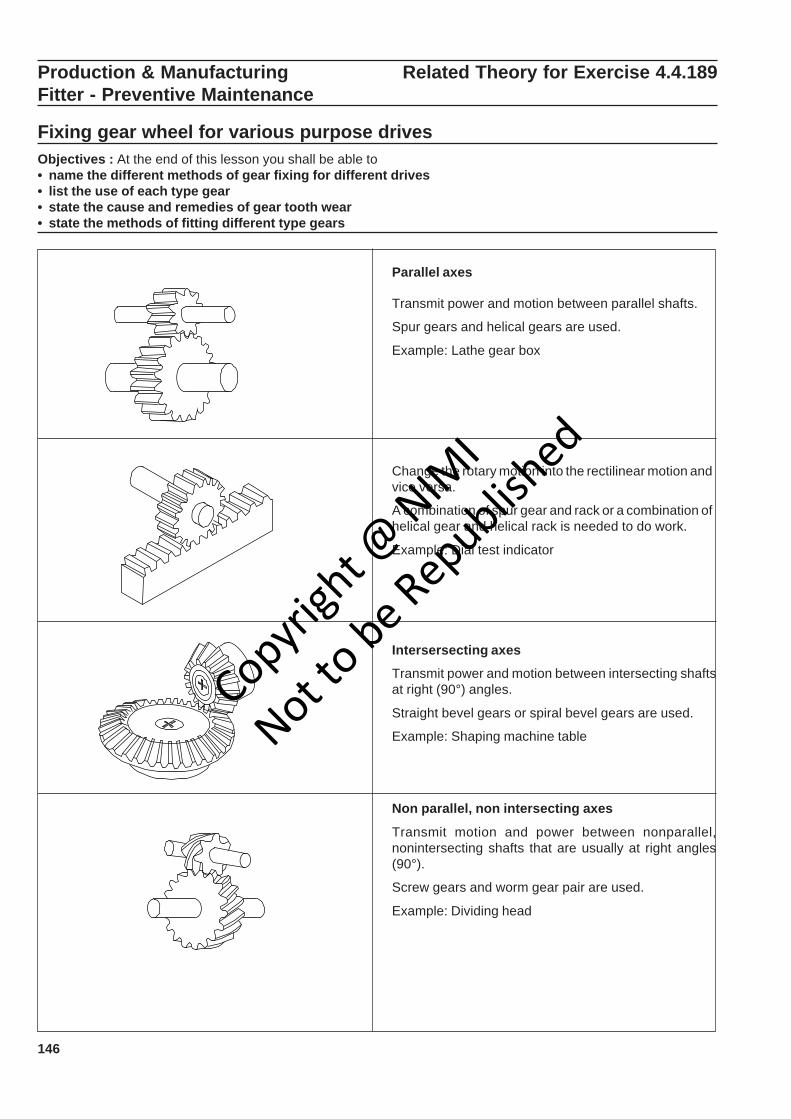
146
Production & Manufacturing Related Theory for Exercise 4.4.189Fitter - Preventive Maintenance
Fixing gear wheel for various purpose drivesObjectives : At the end of this lesson you shall be able to• name the different methods of gear fixing for different drives• list the use of each type gear• state the cause and remedies of gear tooth wear• state the methods of fitting different type gears
Parallel axes
Transmit power and motion between parallel shafts.
Spur gears and helical gears are used.
Example: Lathe gear box
Change the rotary motion into the rectilinear motion andvice versa.
A combination of spur gear and rack or a combination ofhelical gear and helical rack is needed to do work.
Example: Dial test indicator
Intersersecting axes
Transmit power and motion between intersecting shaftsat right (90°) angles.
Straight bevel gears or spiral bevel gears are used.
Example: Shaping machine table
Non parallel, non intersecting axes
Transmit motion and power between nonparallel,nonintersecting shafts that are usually at right angles(90°).
Screw gears and worm gear pair are used.
Example: Dividing head
Copyrigh
t @ NIM
I
Not to be Republish
ed

147
Wear and tear of toothed wheel and their remedies
Wear: A surface phenomenon in which layers of materialis removed or “worn away”
Moderate wear
Cause: Wear in progress,in a dequate lubricant film
Remedies: Increasing lubricating film strength, sufficientoil is supplied to working surfaces.
Abrasive wear
Cause: foreign material in the lubrication metallic debris.from the gear.
Corrosive wear
Cause: Corrosive elements in oil
Remedies: Use of filter and use high thick lubricating oil.
Crushing
Causes: Surface irregularities,misalignment of gears.
Remedies: Smooth gear surfaces, reduce dynamicloading limit, keeping the load below the endurance limit.
Production & Manufacturing : Fitter (NSQF - Level - 5): Related Theory for Exercise 4.4.189
Exessive wear
Copyrigh
t @ NIM
I
Not to be Republish
ed

148 Production & Manufacturing : Fitter (NSQF- Level - 5): Related Theory for Exercise 4.3.189
Fracture: Fracture is caused by breakage of whole tooth
Fatigue breakage
Cause: Extreme tooth loads, notches
Remedy: Higher strength material,load in with endurancelimit
Rippling
Cause: Cyclic loads under high contact stresses.
Remedy: Case hardening of tooth surface.
Method of fitting spiral gear, helical gear, bevel gearand worm gear
Worm and worm wheel
The mounting of worm gears is critical to theirimplementation. Multiple points of contact are necessarybetween the drive and gear, so high work loads do notoverwork the same lead angle, which could lead to gearfailure. Enveloped worm gear sets are normally assembledin the same housing, to ensure proper mating and due tothe sets’ small footprint.
Consider the gear center, bore diameter and shaftdiameter. The gear center can be a bored hole or anintegral shaft. The bore diameter is the diameter of thecenter hole. The shaft diameter is the diameter of theshaft for gears with an integral shaft. Worms and wormgears can be mounted on a hub or shaft. A hub is acylindrical projection on one or both sides of a worm orworm gear, often for the provision of a screw or othershaft attachment mechanism.Hubless gears are typicallyattached via press fit, adhesive or internal keyway.
Shaft mounting choices include the following:
Keyway: One or more square cutouts exist in the gearbore for exact mounting on the shaft.
Overload
Cause: Overload which exceeds tensile strength
Remedy: Torque limiting overload protectiondevices
Plastic flow: Cold working of tooth surfaces caused byhigh contact stress.
Cold flow
Causes: Rolling and peening action of much underheavy loads.
Copyrigh
t @ NIM
I
Not to be Republish
ed

149Production & Manufacturing : Fitter (NSQF- Level - 5): Related Theory for Exercise 4.3.189
Set screw: The gear is attached to the shaft by screwsthrough the hub.
Split: The hub is split into several pieces that are tighteneddown by a separate clamp to grip the shaft.
Simple bore: A straight bore designed for adhesiveattachment.
Helical gear
Consider the gear center, bore diameter and shaftdiameter.The gear center can be a bored hole or anintegral shaft. The bore diameter is the diameter of thecenter hole. The shaft diameter is the diameter of theshaft for gears with an integral shaft. Helical gears can bemounted on a hub or shaft. A hub is a cylindrical projectionon one or both sides of a helical gear, often for theprovision of a screw or other shaft attachment mechanism.Hubless gears are typically attached via press fit, adhesiveor internal keyway.
Illustration Procedure
• Prepare the input side.
• Important: The round chamfer on the bore ofthe pinion must lie in the direction of the shaftshouder.
Mount the pinion onto the shaft.
Copyrigh
t @ NIM
I
Not to be Republish
ed
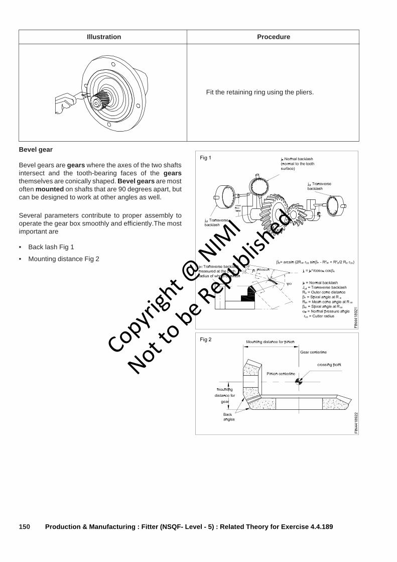
150 Production & Manufacturing : Fitter (NSQF- Level - 5) : Related Theory for Exercise 4.4.189
Illustration Procedure
Fit the retaining ring using the pliers.
Bevel gear
Bevel gears are gears where the axes of the two shaftsintersect and the tooth-bearing faces of the gearsthemselves are conically shaped. Bevel gears are mostoften mounted on shafts that are 90 degrees apart, butcan be designed to work at other angles as well.
Several parameters contribute to proper assembly tooperate the gear box smoothly and efficiently.The mostimportant are
• Back lash Fig 1
• Mounting distance Fig 2
Copyrigh
t @ NIM
I
Not to be Republish
ed
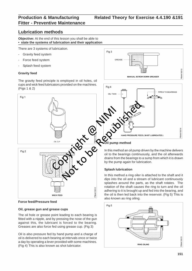
151
Production & Manufacturing Related Theory for Exercise 4.4.190 &191Fitter - Preventive Maintenance
Lubrication methodsObjective: At the end of this lesson you shall be able to• state the systems of lubrication and their application
There are 3 systems of lubrication.
- Gravity feed system
- Force feed system
- Splash feed system
Gravity feed
The gravity feed principle is employed in oil holes, oilcups and wick feed lubricators provided on the machines.(Figs 1 & 2)
Force feed/Pressure feed
Oil, grease gun and grease cups
The oil hole or grease point leading to each bearing isfitted with a nipple, and by pressing the nose of the gunagainst this, the lubricant is forced to the bearing.Greases are also force fed using grease cup. (Fig 3)
Oil is also pressure fed by hand pump and a charge ofoil is delivered to each bearing at intervals once or twicea day by operating a lever provided with some machines.(Fig 4) This is also known as shot lubricator.
Oil pump method
In this method an oil pump driven by the machine deliversoil to the bearings continuously, and the oil afterwardsdrains from the bearings to a sump from which it is drawnby the pump again for lubrication.
Splash lubrication
In this method a ring oiler is attached to the shaft and itdips into the oil and a stream of lubricant continuouslysplashes around the parts, as the shaft rotates. Therotation of the shaft causes the ring to turn and the oiladhering to it is brought up and fed into the bearing, andthe oil is then led back into the reservoir. (Fig 5) This isalso known as ring oiling.
Copyrigh
t @ NIM
I
Not to be Republish
ed

152 Production & Manufacturing : Fitter (NSQF- Level - 5): Related Theory for Exercise 4.4.190 & 191
In other systems one of the rotating elements comes incontact with that of the oil level and splash the wholesystem with lubricating oil while working. (Fig 6) Suchsystems can be found in the headstock of a lathemachine and oil engine cylinder.
- Automatic and hydraulic type pressure gun (Fig 8)
Types of grease guns
The following types of grease guns are used forlubricating machines.
- ‘T’ handle pressure gun (Fig 7)
- Lever-type pressure gun (Fig 9)
Lubrication to exposed slideways
The moving parts experience some kind of resistanceeven when the surface of the parts seems to be verysmooth.
The resistance is caused by irregularities which cannotbe detected by the naked eyes.
Without a lubricant the irregularities grip each other asshown in the diagram. (Fig 10)
With a lubricant the gap between the irregularities fillsup and a film of lubricant is formed in between the matingcomponents which eases the movement. (Fig 11)
The slideways are lubricated frequently by an oilcan.(Fig 12)
After cleaning the open gears, oil them and repeatlubrication regularly. (Fig 13)
Copyrigh
t @ NIM
I
Not to be Republish
ed
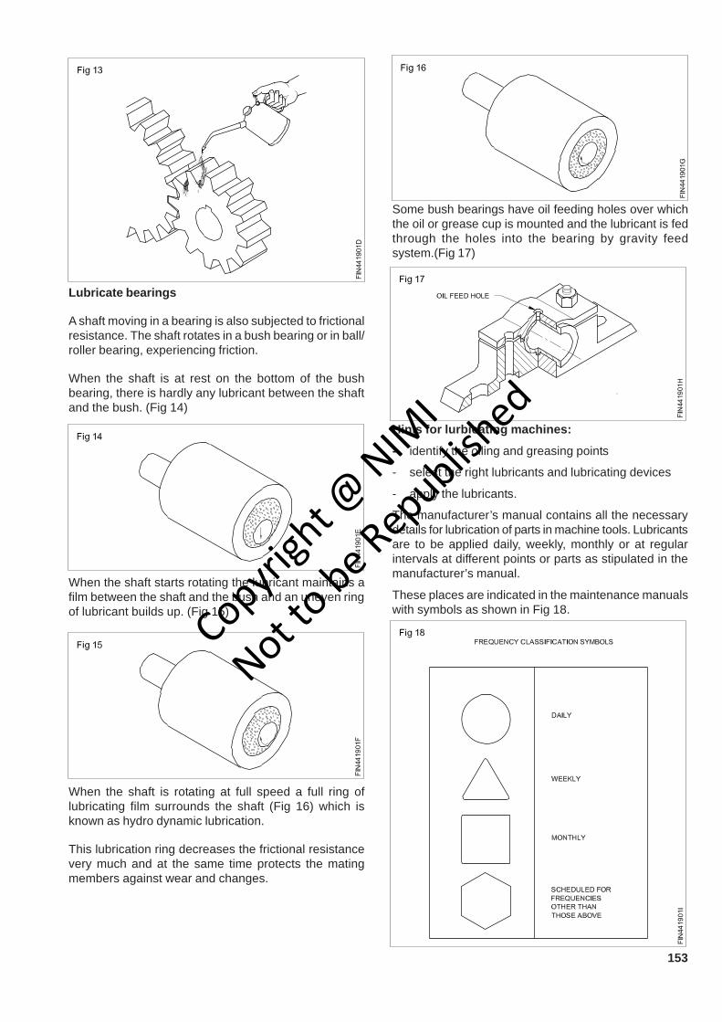
153
Lubricate bearings
A shaft moving in a bearing is also subjected to frictionalresistance. The shaft rotates in a bush bearing or in ball/roller bearing, experiencing friction.
When the shaft is at rest on the bottom of the bushbearing, there is hardly any lubricant between the shaftand the bush. (Fig 14)
When the shaft starts rotating the lubricant maintains afilm between the shaft and the bush and an uneven ringof lubricant builds up. (Fig 15)
When the shaft is rotating at full speed a full ring oflubricating film surrounds the shaft (Fig 16) which isknown as hydro dynamic lubrication.
This lubrication ring decreases the frictional resistancevery much and at the same time protects the matingmembers against wear and changes.
Some bush bearings have oil feeding holes over whichthe oil or grease cup is mounted and the lubricant is fedthrough the holes into the bearing by gravity feedsystem.(Fig 17)
Hints for lurbicating machines:
- identify the oiling and greasing points
- select the right lubricants and lubricating devices
- apply the lubricants.
The manufacturer’s manual contains all the necessarydetails for lubrication of parts in machine tools. Lubricantsare to be applied daily, weekly, monthly or at regularintervals at different points or parts as stipulated in themanufacturer’s manual.
These places are indicated in the maintenance manualswith symbols as shown in Fig 18.
Copyrigh
t @ NIM
I
Not to be Republish
ed

154
Cutting fluidsObjectives: At the end of this lesson you shall be able to• state what is cutting fluid• state the function of cutting fluids & their advantages• state the properties of a good cutting fluid• identify different types of cutting fluids• select appropriate cutting fluids for different materials.
Cutting fluids and compounds are the substances usedfor efficient cutting while cutting operations take place.
Functions
The functions of cutting fluids are:
- to cool the tool as well as the workpiece
- to reduce the friction between the chip and the toolface by lubricating
- to prevent the chip from getting welded to the toolcutting edge
- to flush away the chips
- to prevent corrosion of the work and the machine.
Advantages
As the cutting fluid cools the tool, the tool will retain itshardness for a longer period; so the tool life is more.
Because of the lubricating function, the friction is reducedand the heat generated is less. A higher cutting speedcan be selected.
As the coolant avoids the welding action of the chip to thetool-cutting edge, the built up edge is not formed. Thetool is kept sharp and a good surface finish is obtained.
As the chips are flushed away, the cutting zone will beneat.
The machine or job will not get rusted because thecoolant prevents corrosion.
Properties of a good cutting fluid
A good cutting fluid should be sufficiently viscous.
At cutting temperature, the coolant should not catch fire.
It should have a low evaporation rate.
It should not corrode the workpiece or machine.
It must be stable and should not foam or fume.
It should not create any skin problems to the operator.
Should not give off bad smell or cause itching etc. whichare likely to irritate the operator, thus reducing hisefficiency.
Should be transparent.
Types of cutting fluids
The following are the common cutting fluids.
- Straight mineral oil
- Chemical solution (synthetic fluids)
- Compounded or blended oil
- Fatty oils
- Soluble oil (Emulsified oil-suds)
Straight mineral oil
Straight mineral oils are the coolants which can be usedundiluted. Use of straight mineral oil as a coolant has thefollowing disadvantages.
It gives off a cloud of smoke.
It has little effect as a cutting fluid.
Hence straight mineral oils are poor coolants. But kero-sene which is a straight mineral oil is widely used as acoolant for machining aluminium and its alloys.
Chemical solution (Synthetic oil)
These consist of carefully chosen chemicals in dilutesolution with water. They possess a good flushing and agood cooling action, and are non-corrosive and non-clogging. Hence they are widely used for grinding andsawing. They do not cause infection and skin trouble.They are artificially coloured.
Compounded or blended oil
These oils are used in automatic lathes. These oils aremuch cheaper and have more fluidity than fatty oil.
Production & Manufacturing : Fitter (NSQF- Level - 5): Related Theory for Exercise 4.4.190 & 191
Copyrigh
t @ NIM
I
Not to be Republish
ed

155Production & Manufacturing : Fitter (NSQF- Level - 5): Related Theory for Exercise 4.4.190 & 191
Fatty oil
Lard oil and vegetable oil are fatty oils. They are used onheavy duty machines with less cutting speed. They arealso used on bench-works for cutting threads by taps anddies.
Soluble oil (Emulsified oil)
Water is the cheapest coolant but it is not suitablebecause it causes rust to ferrous metals. An oil calledsoluble oil is added to water which gets a non-corrosiveeffect with water in the ratio of about 1: 20. It dissolvesin water giving a white milky solution. Soluble oil is an oilblend mixed with an emulsifier.
Other ingredients are mixed with the oil to give betterprotection against corrosion, and help in the preventionof skin irritations.
Soluble oil is generally used as a cutting fluid for centrelathes, drilling, milling and sawing.
Soft soap and caustic soda serve as emulsifying agents.
A chart showing coolants for different metals is givenbelow.
Recommended cutting fluids for various metals and different operations
Material Drilling Reaming Threading Turning Milling
Aluminium Soluble oil Soluble oil Soluble oil Soluble oil Soluble oilKerosene Kerosene Kerosene Lard oilKerosene and Mineral oil Lard oil Mineral oillard oil Dry
Brass Dry Dry Soluble oil Soluble oil Drysoluble oil soluble oil Lard oil soluble oilMineral oilLard oil
Bronze Dry Dry Soluble oil Soluble oil Drysoluble oil soluble oil Lard oil soluble oilMineral oil Mineral oil Mineral oilLard oil Lard oil Lard oil
Cast iron Dry Dry Dry Dry DryAir jet soluble oil sulphurized oil soluble oil soluble oilSoluble oil Mineral lard oil Mineral lard oil
Copper Dry Soluble oil Soluble oil Soluble oil Drysoluble oil Lard oil Lard oil soluble oilMineral lard oilKerosene
Steel Soluble oil Soluble oil Sulphurized oil Soluble oil Soluble oilalloys Sulphurized oil Sulphurized oil Lard oil Mineral
Mineral lard oil Mineral lard oil
General Soluble oil Soluble oil Sulphurized oil Soluble oil Soluble oilpurpose Sulphurized oil Sulphurized oil Lard oil Lard oilsteel Lard oil Lard oil
Mineral lard oil
Copyrigh
t @ NIM
I
Not to be Republish
ed
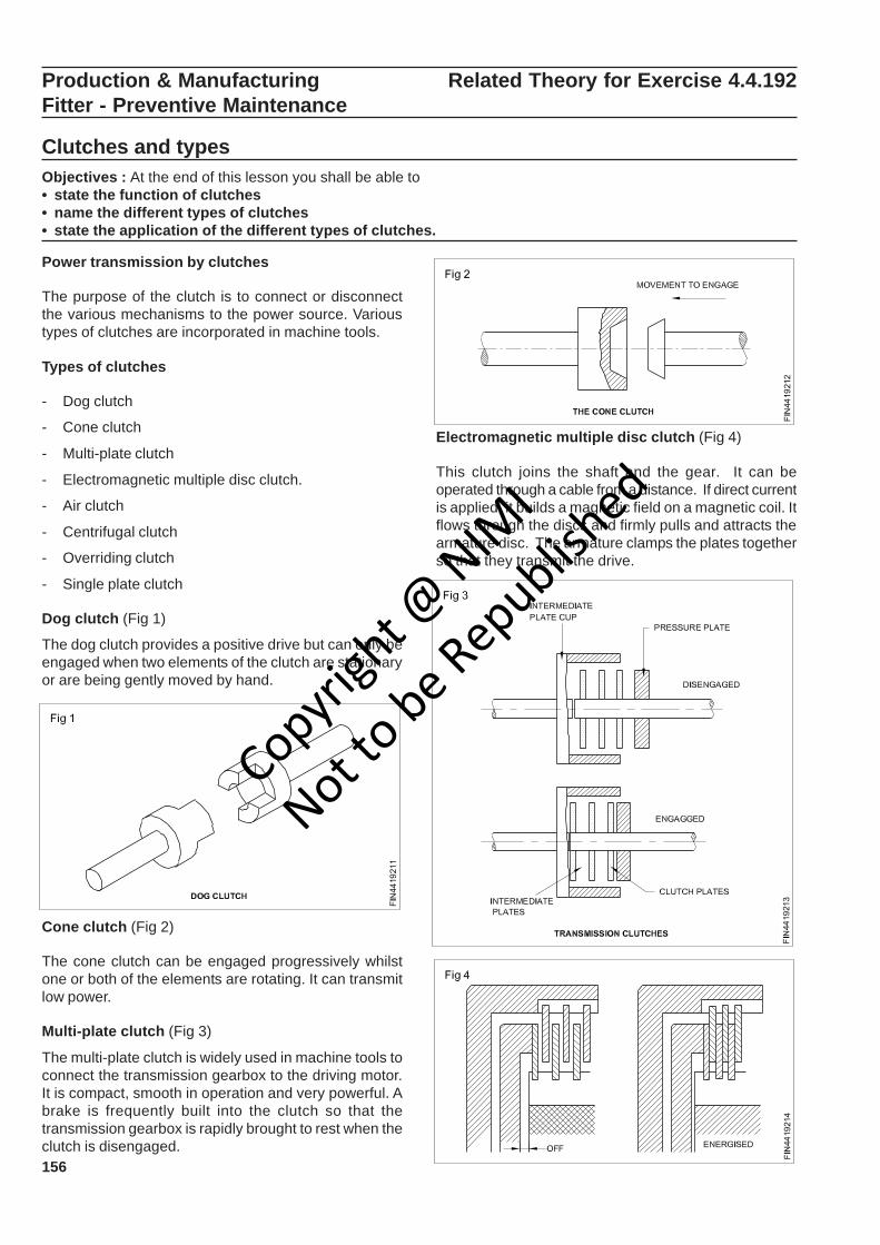
156
Electromagnetic multiple disc clutch (Fig 4)
This clutch joins the shaft and the gear. It can beoperated through a cable from a distance. If direct currentis applied, it builds a magnetic field on a magnetic coil. Itflows through the discs and firmly pulls and attracts thearmature disc. The armature clamps the plates togetherso that they transmit the drive.
Cone clutch (Fig 2)
The cone clutch can be engaged progressively whilstone or both of the elements are rotating. It can transmitlow power.
Multi-plate clutch (Fig 3)
The multi-plate clutch is widely used in machine tools toconnect the transmission gearbox to the driving motor.It is compact, smooth in operation and very powerful. Abrake is frequently built into the clutch so that thetransmission gearbox is rapidly brought to rest when theclutch is disengaged.
Production & Manufacturing Related Theory for Exercise 4.4.192Fitter - Preventive Maintenance
Clutches and typesObjectives : At the end of this lesson you shall be able to• state the function of clutches• name the different types of clutches• state the application of the different types of clutches.
Power transmission by clutches
The purpose of the clutch is to connect or disconnectthe various mechanisms to the power source. Varioustypes of clutches are incorporated in machine tools.
Types of clutches
- Dog clutch
- Cone clutch
- Multi-plate clutch
- Electromagnetic multiple disc clutch.
- Air clutch
- Centrifugal clutch
- Overriding clutch
- Single plate clutch
Dog clutch (Fig 1)
The dog clutch provides a positive drive but can only beengaged when two elements of the clutch are stationaryor are being gently moved by hand.
Copyrigh
t @ NIM
I
Not to be Republish
ed
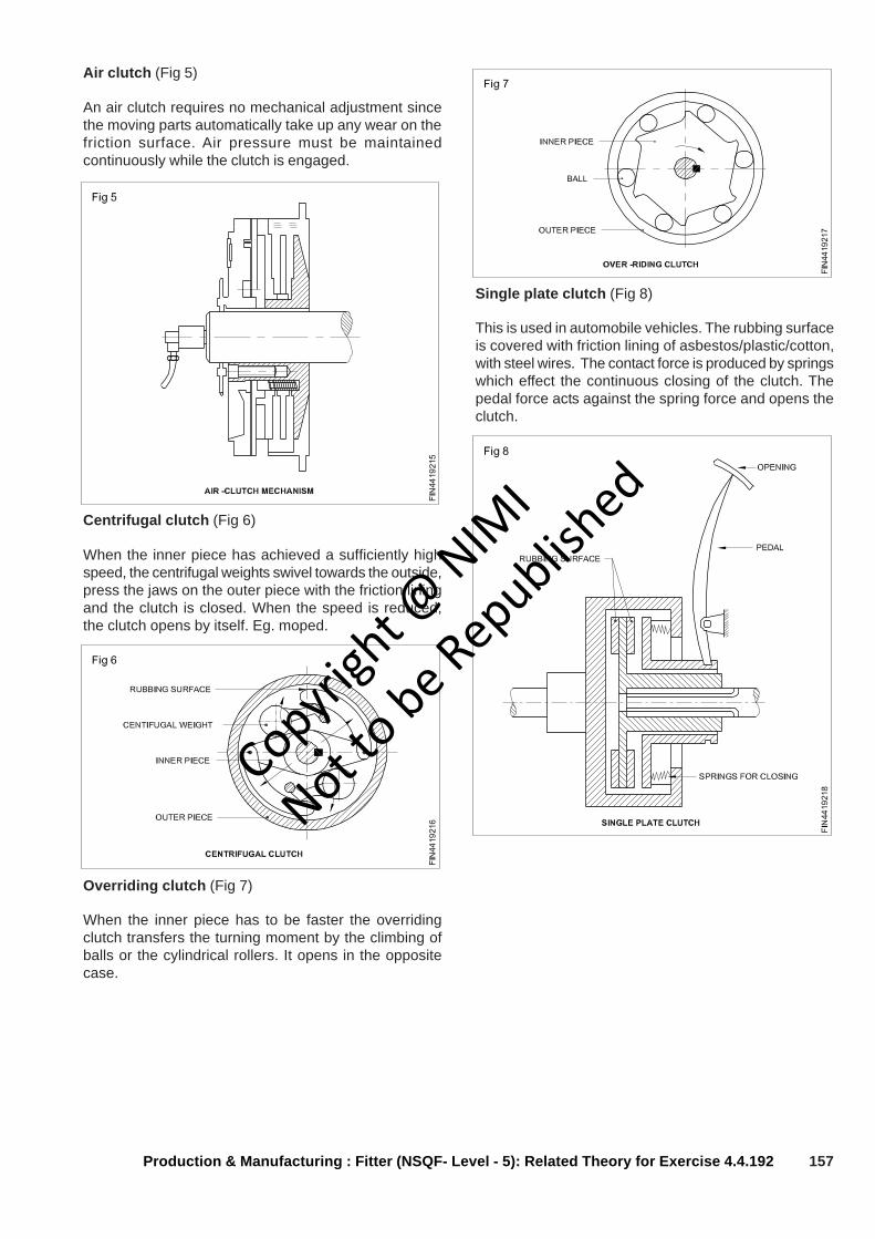
157
Centrifugal clutch (Fig 6)
When the inner piece has achieved a sufficiently highspeed, the centrifugal weights swivel towards the outside,press the jaws on the outer piece with the friction liningand the clutch is closed. When the speed is reduced,the clutch opens by itself. Eg. moped.
Production & Manufacturing : Fitter (NSQF- Level - 5): Related Theory for Exercise 4.4.192
Air clutch (Fig 5)
An air clutch requires no mechanical adjustment sincethe moving parts automatically take up any wear on thefriction surface. Air pressure must be maintainedcontinuously while the clutch is engaged.
Overriding clutch (Fig 7)
When the inner piece has to be faster the overridingclutch transfers the turning moment by the climbing ofballs or the cylindrical rollers. It opens in the oppositecase.
Single plate clutch (Fig 8)
This is used in automobile vehicles. The rubbing surfaceis covered with friction lining of asbestos/plastic/cotton,with steel wires. The contact force is produced by springswhich effect the continuous closing of the clutch. Thepedal force acts against the spring force and opens theclutch.
Copyrigh
t @ NIM
I
Not to be Republish
ed

158
Lock washers
A lock washer is used to prevent a bolt or nut fromloosening under vibration.
The split ring lock washer is being rapidly replaced bylock washers designed for specific applications. (Fig 2)
Tooth type lock washers
These washers have teeth that bite deep into both screwhead and work surface. Their design is such that theyactually lock lighter as vibrations increase.
External type
Should be used where possible as it provides the greatestresistance. (Fig 3)
Internal type
Used with small head screws and where it is desirable tohide the teeth either for appearance or to prevent snagging.(Fig 4)
Internal and external type
Used when the mounting holes are over size. (Fig 5)
Countersunk type
For use with flat or oval type head screws. (Fig 6)
Production & Manufacturing Related Theory for Exercise 4.4.193Fitter - Preventive Maintenance
Washer types and calculation of sizesObjectives : At the end of this lesson you shall be able to• state the various types of washers• determine the sizes of washers• state the uses of washerWashers
Washers are used to distribute the clamping pressureover a larger area, and prevent the surface damaged(marking). they are also provide an increased bearingsurface for bolt heads and nuts. Washers aremanufactured in light, medium, heavy and extra heavyseries. (Fig 1)
Copyrigh
t @ NIM
I
Not to be Republish
ed
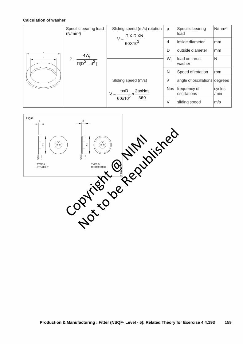
159
Calculation of washer
Specific bearing load Sliding speed (m/s) rotation p Specific bearing N/mm2
(N/mm2) load
d inside diameter mm
D outside diameter mm
Wt load on thrust Nwasher
N Speed of rotation rpm
Sliding speed (m/s) ∂ angle of oscillations degrees
Nos frequency of cyclesoscillations /min
V sliding speed m/s
360X10
Π X D XNV =
)2d2Π(Dt4W
P−
=
Production & Manufacturing : Fitter (NSQF- Level - 5): Related Theory for Exercise 4.4.193
360
2axNosx360x10
πxDV =
Copyrigh
t @ NIM
I
Not to be Republish
ed
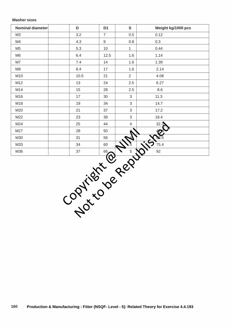
160
Washer sizes
Nominal diameter D D1 S Weight kg/1000 pcs
M3 3.2 7 0.5 0.12
M4 4.3 9 0.8 0.3
M5 5.3 10 1 0.44
M6 6.4 12.5 1.6 1.14
M7 7.4 14 1.6 1.39
M8 8.4 17 1.6 2.14
M10 10.5 21 2 4.08
M12 13 24 2.5 6.27
M14 15 28 2.5 8.6
M16 17 30 3 11.3
M18 19 34 3 14.7
M20 21 37 3 17.2
M22 23 39 3 18.4
M24 25 44 4 32.3
M27 28 50 4 42.8
M30 31 56 4 53.6
M33 34 60 5 75.4
M36 37 66 5 92
Production & Manufacturing : Fitter (NSQF- Level - 5): Related Theory for Exercise 4.4.193
Copyrigh
t @ NIM
I
Not to be Republish
ed
161
Production & Manufacturing Related Theory for Exercise 4.4.194Fitter - Preventive Maintenance
Chain and wire rope for power transmissionObjectives : At the end of this lesson you shall be able to• state the uses of rope drives• list the materials of rope• state the purpose of jackey pulleys• state the uses of chain drive• list the advantages of chain drive.
Ropes and rope drive
The ropes are made from cotton, hemp, manila, syntheticjute, steel wire, etc.
Rope drives are used for long distance and for largeamounts of power transmission. The rope drives aremainly employed in mining and textile industries. Ropedrives can be employed when there is a misalignmentbetween the pulleys within limits and in fluctuatingtemperature and humidity conditions. Fig 1 shows acontinuous rope drive in which a single rope passes overthe sheaves several times, and the slackness being takenup by a tension carriage.
Wrapping angle of pulley
Fig 2 and 3 illustrate the contact area of the belt andwrapping angle. If the wrapping angle is big, the pulleycan transmit high torque. If the contact area and wrappingangle is less, it can transmit low torque.
Jockey pulley
The contact surface between the belt and the pulley isincreased by providing a jockey pulley which increasesthe wrapping angle and transmits high torque.
The jockey pulley should be put on the slack side of thebelt near the driving pulley. (Fig 4)
Copyrigh
t @ NIM
I
Not to be Republish
ed
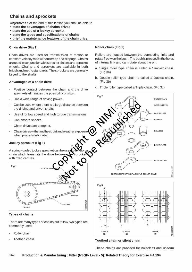
162
Chains and sprocketsObjectives : At the end of this lesson you shall be able to• state the advantages of chains drives• state the use of a jockey sprocket• state the types and specifications of chains• brief the maintenance features of the chain drive.
Production & Manufacturing : Fitter (NSQF- Level - 5): Related Theory for Exercise 4.4.194
Chain drive (Fig 1)
Chain drives are used for transmission of motion atconstant velocity ratio without creep and slippage. Chainsare used in conjunction with sprocket pinions and sprocketwheels. Chains and sprockets are available in bothbritish and metric standards. The sprockets are generallykeyed to the shafts.
Advantages of a chain drive
- Positive contact between the chain and the drivesprockets eliminates the possibility of slips.
- Has a wide range of driving power.
- Can be used where there is a large distance betweenthe driving and driven shafts.
- Useful for low speed and high torque transmissions.
- Can absorb shocks.
- Chain drives are compact.
- Chain drives withstand heat, dirt and weather exposurewhen properly lubricated.
Jockey sprocket (Fig 1)
A spring-loaded jockey sprocket can be used to tension achain which transmits the drive between the sprocketswith fixed centres.
Types of chains
There are many types of chains but follow two types arecommonly used.
- Roller chain
- Toothed chain
Roller chain (Fig 2)
Rollers are housed between the connecting links androtate freely on the bush. The bush is pressed in the holesof internal link and can rotate about the pin.
a. Single roller type chain is called a Simplex chain.(Fig 3a)
b. Double roller type chain is called a Duplex chain.(Fig 3b)
c. Triple roller type called a Triple chain. (Fig 3c)
Toothed chain or silent chain
These chains are provided for noiseless and uniform
Copyrigh
t @ NIM
I
Not to be Republish
ed
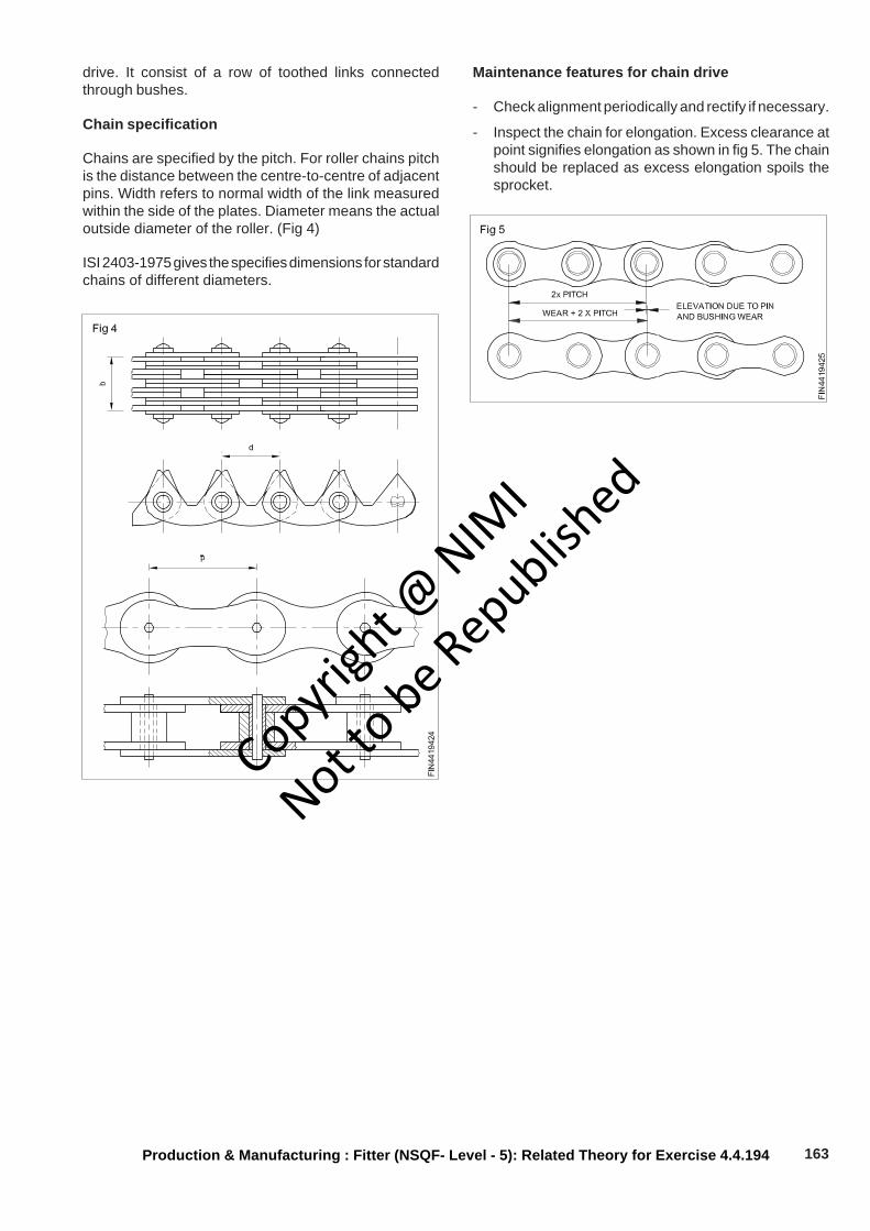
163Production & Manufacturing : Fitter (NSQF- Level - 5): Related Theory for Exercise 4.4.194
drive. It consist of a row of toothed links connectedthrough bushes.
Chain specification
Chains are specified by the pitch. For roller chains pitchis the distance between the centre-to-centre of adjacentpins. Width refers to normal width of the link measuredwithin the side of the plates. Diameter means the actualoutside diameter of the roller. (Fig 4)
ISI 2403-1975 gives the specifies dimensions for standardchains of different diameters.
Maintenance features for chain drive
- Check alignment periodically and rectify if necessary.
- Inspect the chain for elongation. Excess clearance atpoint signifies elongation as shown in fig 5. The chainshould be replaced as excess elongation spoils thesprocket.
Copyrigh
t @ NIM
I
Not to be Republish
ed
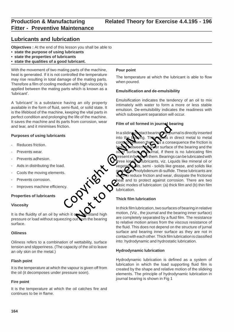
164
Production & Manufacturing Related Theory for Exercise 4.4.195 - 196Fitter - Preventive Maintenance
Lubricants and lubricationObjectives : At the end of this lesson you shall be able to• state the purpose of using lubricants• state the properties of lubricants• state the qualities of a good lubricant.
With the movement of two mating parts of the machine,heat is generated. If it is not controlled the temperaturemay rise resulting in total damage of the mating parts.Therefore a film of cooling medium with high viscocity isapplied between the mating parts which is known as a‘lubricant’.
A ‘lubricant’ is a substance having an oily propertyavailable in the form of fluid, semi-fluid, or solid state. Itis the lifeblood of the machine, keeping the vital parts inperfect condition and prolonging the life of the machine.It saves the machine and its parts from corrosion, wearand tear, and it minimises friction.
Purposes of using lubricants
- Reduces friction.
- Prevents wear.
- Prevents adhesion.
- Aids in distributing the load.
- Cools the moving elements.
- Prevents corrosion.
- Improves machine efficiency.
Properties of lubricants
Viscosity
It is the fluidity of an oil by which it can withstand highpressure or load without squeezing out from the bearingsurface.
Oiliness
Oiliness refers to a combination of wettability, surfacetension and slipperiness. (The capacity of the oil to leavean oily skin on the metal.)
Flash point
It is the temperature at which the vapour is given off fromthe oil (it decomposes under pressure soon).
Fire point
It is the temperature at which the oil catches fire andcontinues to be in flame.
Pour point
The temperature at which the lubricant is able to flowwhen poured.
Emulsification and de-emulsibility
Emulsification indicates the tendency of an oil to mixintimately with water to form a more or less stableemulsion. De-emulsibility indicates the readiness withwhich subsequent separation will occur.
Film of oil formed in journal bearing
In a sliding contact bearing, the journal is directly insertedinto the bearing. This results in direct metal to metalcontact between them. As a consequence the friction ishigher between the inner surface of the bearing and theouter surface of journal, if there is no lubricating filmpresent in between them. Bearings can be lubricated withthree kinds of lubricants, viz. Liquids like mineral oil orvegetable oils, semi - solids like grease, and solids likegraphite or molybdenum di-sulfide. These lubricants areused to reduce friction and wear, dissipate the frictionalheat and to protect against corrosion. There are twobasic modes of lubrication: (a) thick film and (b) thin filmlubrication.
Thick film lubrication
In thick film lubrication, two surfaces of bearing in relativemotion, (Viz., the journal and the bearing inner surface)are completely separated by a fluid film. The resistanceto relative motion arises from the viscous resistance ofthe fluid. This does not depend on the structure of jurnalsurface and bearing inner surface as they are not incontact with each other. Thick film lubrication is classifiedinto: hydrodynamic and hydrostatic lubrication.
Hydrodynamic lubrication
Hydrodynamic lubrication is defined as a system oflubrication in which the load supporting fluid film iscreated by the shape and relative motion of the slideingelements. The principle of hydrodynamic lubrication injournal bearing is shown in Fig 1
Copyrigh
t @ NIM
I
Not to be Republish
ed
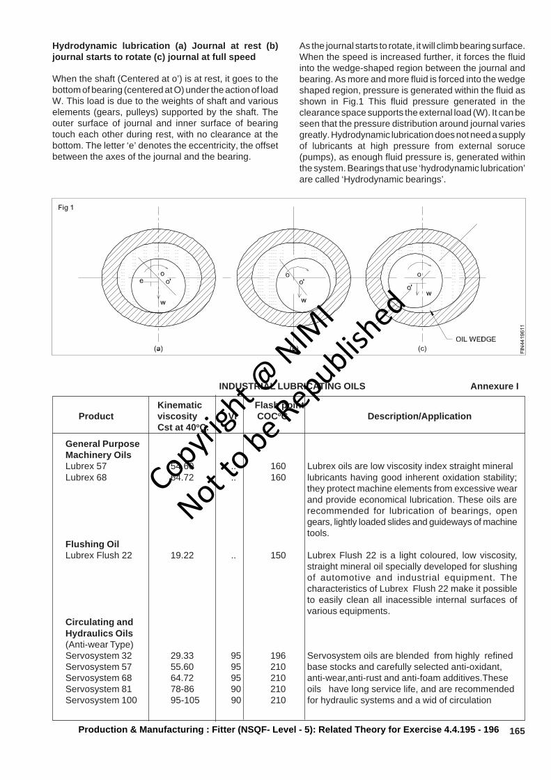
165Production & Manufacturing : Fitter (NSQF- Level - 5): Related Theory for Exercise 4.4.195 - 196
Hydrodynamic lubrication (a) Journal at rest (b)journal starts to rotate (c) journal at full speed
When the shaft (Centered at o’) is at rest, it goes to thebottom of bearing (centered at O) under the action of loadW. This load is due to the weights of shaft and variouselements (gears, pulleys) supported by the shaft. Theouter surface of journal and inner surface of bearingtouch each other during rest, with no clearance at thebottom. The letter ‘e’ denotes the eccentricity, the offsetbetween the axes of the journal and the bearing.
As the journal starts to rotate, it will climb bearing surface.When the speed is increased further, it forces the fluidinto the wedge-shaped region between the journal andbearing. As more and more fluid is forced into the wedgeshaped region, pressure is generated within the fluid asshown in Fig.1 This fluid pressure generated in theclearance space supports the external load (W). It can beseen that the pressure distribution around journal variesgreatly. Hydrodynamic lubrication does not need a supplyof lubricants at high pressure from external soruce(pumps), as enough fluid pressure is, generated withinthe system. Bearings that use ‘hydrodynamic lubrication’are called ‘Hydrodynamic bearings’.
INDUSTRIAL LUBRICATING OILS Annexure I
Kinematic Flash pointProduct viscosity VI COCoC Description/Application
Cst at 40oC.
General PurposeMachinery OilsLubrex 57 54.60 .. 160 Lubrex oils are low viscosity index straight mineralLubrex 68 64.72 .. 160 lubricants having good inherent oxidation stability;
they protect machine elements from excessive wearand provide economical lubrication. These oils arerecommended for lubrication of bearings, opengears, lightly loaded slides and guideways of machinetools.
Flushing OilLubrex Flush 22 19.22 .. 150 Lubrex Flush 22 is a light coloured, low viscosity,
straight mineral oil specially developed for slushingof automotive and industrial equipment. Thecharacteristics of Lubrex Flush 22 make it possibleto easily clean all inacessible internal surfaces ofvarious equipments.
Circulating andHydraulics Oils(Anti-wear Type)Servosystem 32 29.33 95 196 Servosystem oils are blended from highly refinedServosystem 57 55.60 95 210 base stocks and carefully selected anti-oxidant,Servosystem 68 64.72 95 210 anti-wear,anti-rust and anti-foam additives.TheseServosystem 81 78-86 90 210 oils have long service life, and are recommendedServosystem 100 95-105 90 210 for hydraulic systems and a wid of circulation
Copyrigh
t @ NIM
I
Not to be Republish
ed
166 Production & Manufacturing : Fitter (NSQF- Level - 5): Related Theory for Exercise 4.4.195 - 196
Servosystem 150 145-155 90 230 systems of industrial and automotive equipment.These oils are also used for compressor crankcase lubrication, but are not recommended forlubrication of turbines and equipment having silvercoated components.
Spindle OilsServospin 2 2.0-2.4 .. 70 Servospin oils are low viscosity lubricants contain-Servospin 5 4.5-5.0 .. 70 ing anti-wear, anti-oxidant, anti-rust and anti-foamServospin 12 11-14 90 144 additives. These oils are recommended for lubrica-
tion of textile and machine tool spindle bearings, tim-ing gears, positive displacement blowers, and fortracer mechanism and hydraulic systems of certainhigh precision machine tools.
Machinery OilsServoline 32 29.33 .. 152 Servoline oils provide good oiliness for generalServoline 46 42.50 .. 164 lubrication even under boundary lubrication condi-Servoline 68 64-72 .. 176 tions, protect parts against rust and corrosion and
maintain thin film strength and anti-rust additives.Servoline oils are general purpose lubricants for allloss lubrication systems of textile mills, paper mills,machine tools.
Gear OilsServomesh 68 64-72 90 204 Servomesh oils are industrial gear oils blended withServomesh 150 145-155 90 204 lead and sulphur compounds. These oils provideServomesh 257 250-280 90 232 resistance to deposit formation, protect metal com-
ponents against rust and corrosion, separate easilyfrom water and are non-corrosive to ferrous and non-ferrous metals. Servomesh oils are recommendedfor lubrication of industrial gears, plain and anti-fric-tion bearings subjected to shock and heavy loadsand should be used in systems were operating tem
Copyrigh
t @ NIM
I
Not to be Republish
ed
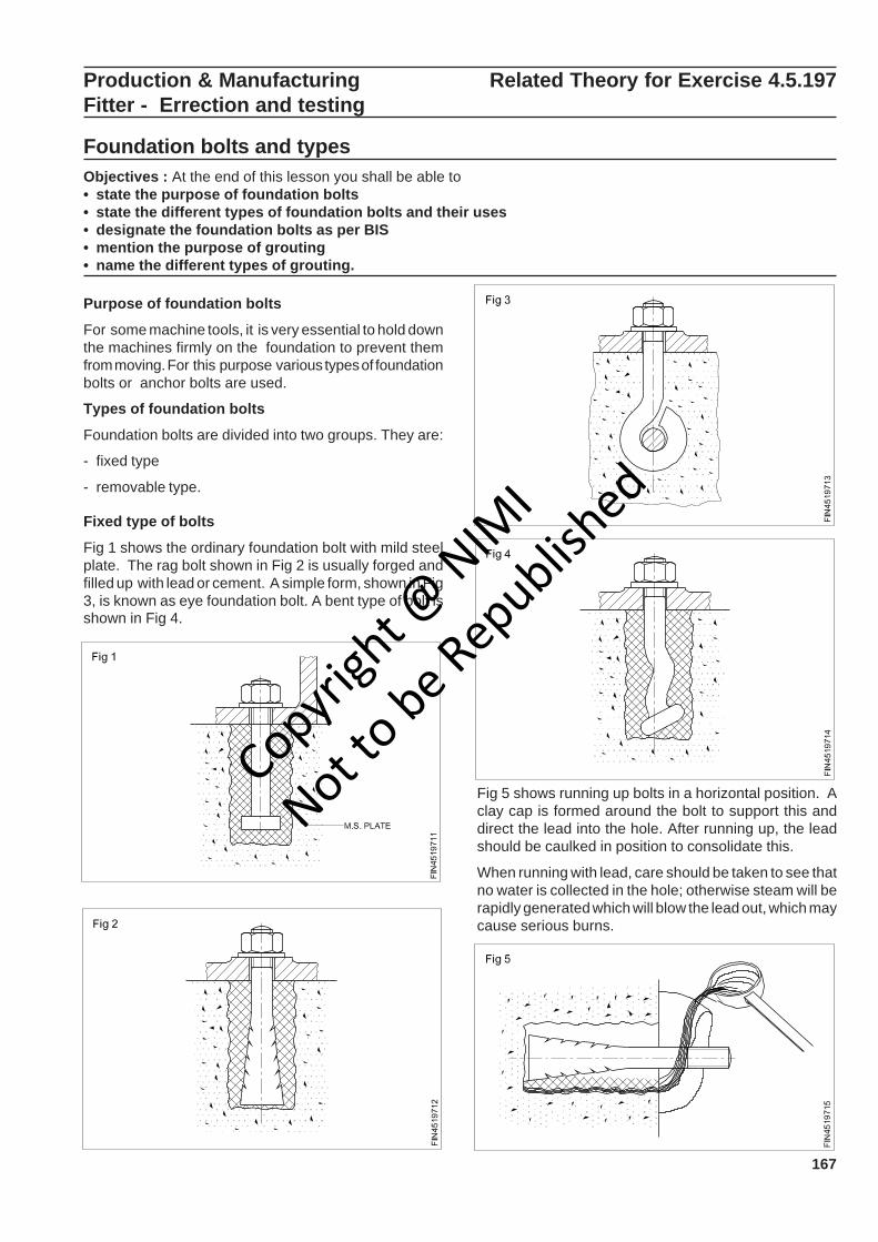
167
Fig 5 shows running up bolts in a horizontal position. Aclay cap is formed around the bolt to support this anddirect the lead into the hole. After running up, the leadshould be caulked in position to consolidate this.
When running with lead, care should be taken to see thatno water is collected in the hole; otherwise steam will berapidly generated which will blow the lead out, which maycause serious burns.
Production & Manufacturing Related Theory for Exercise 4.5.197Fitter - Errection and testing
Foundation bolts and typesObjectives : At the end of this lesson you shall be able to• state the purpose of foundation bolts• state the different types of foundation bolts and their uses• designate the foundation bolts as per BIS• mention the purpose of grouting• name the different types of grouting.
Purpose of foundation bolts
For some machine tools, it is very essential to hold downthe machines firmly on the foundation to prevent themfrom moving. For this purpose various types of foundationbolts or anchor bolts are used.
Types of foundation bolts
Foundation bolts are divided into two groups. They are:
- fixed type
- removable type.
Fixed type of bolts
Fig 1 shows the ordinary foundation bolt with mild steelplate. The rag bolt shown in Fig 2 is usually forged andfilled up with lead or cement. A simple form, shown in Fig3, is known as eye foundation bolt. A bent type of bolt isshown in Fig 4.
Copyrigh
t @ NIM
I
Not to be Republish
ed
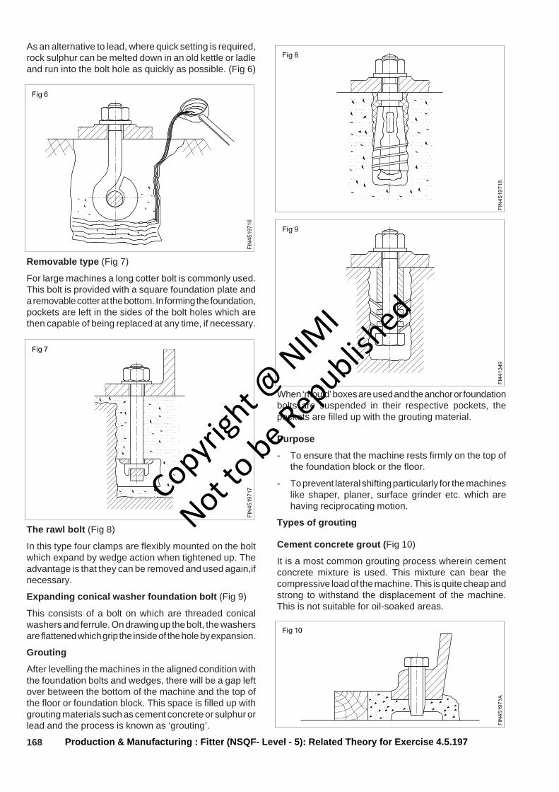
168
As an alternative to lead, where quick setting is required,rock sulphur can be melted down in an old kettle or ladleand run into the bolt hole as quickly as possible. (Fig 6)
Removable type (Fig 7)
For large machines a long cotter bolt is commonly used.This bolt is provided with a square foundation plate anda removable cotter at the bottom. In forming the foundation,pockets are left in the sides of the bolt holes which arethen capable of being replaced at any time, if necessary.
The rawl bolt (Fig 8)
In this type four clamps are flexibly mounted on the boltwhich expand by wedge action when tightened up. Theadvantage is that they can be removed and used again,ifnecessary.
Expanding conical washer foundation bolt (Fig 9)
This consists of a bolt on which are threaded conicalwashers and ferrule. On drawing up the bolt, the washersare flattened which grip the inside of the hole by expansion.
Grouting
After levelling the machines in the aligned condition withthe foundation bolts and wedges, there will be a gap leftover between the bottom of the machine and the top ofthe floor or foundation block. This space is filled up withgrouting materials such as cement concrete or sulphur orlead and the process is known as ‘grouting’.
When ‘mould’ boxes are used and the anchor or foundationbolts are suspended in their respective pockets, thepockets are filled up with the grouting material.
Purpose
- To ensure that the machine rests firmly on the top ofthe foundation block or the floor.
- To prevent lateral shifting particularly for the machineslike shaper, planer, surface grinder etc. which arehaving reciprocating motion.
Types of grouting
Cement concrete grout (Fig 10)
It is a most common grouting process wherein cementconcrete mixture is used. This mixture can bear thecompressive load of the machine. This is quite cheap andstrong to withstand the displacement of the machine.This is not suitable for oil-soaked areas.
Production & Manufacturing : Fitter (NSQF- Level - 5): Related Theory for Exercise 4.5.197
Copyrigh
t @ NIM
I
Not to be Republish
ed
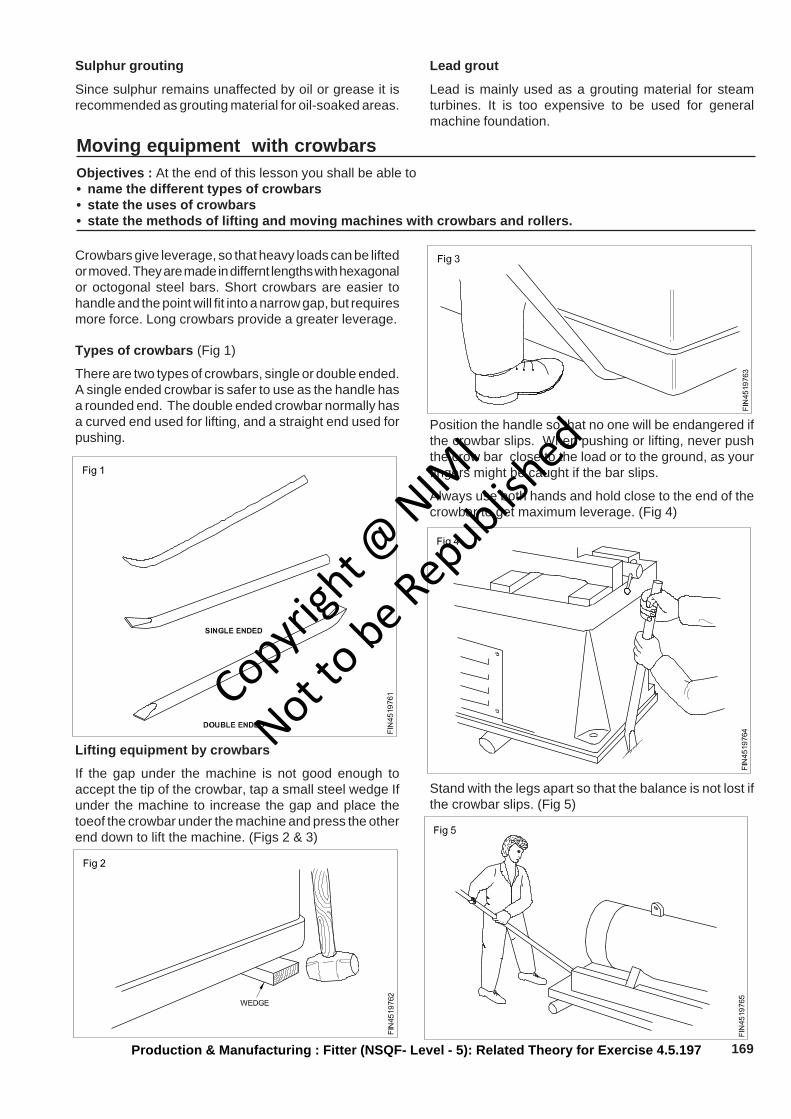
169
Sulphur grouting
Since sulphur remains unaffected by oil or grease it isrecommended as grouting material for oil-soaked areas.
Lead grout
Lead is mainly used as a grouting material for steamturbines. It is too expensive to be used for generalmachine foundation.
Moving equipment with crowbarsObjectives : At the end of this lesson you shall be able to• name the different types of crowbars• state the uses of crowbars• state the methods of lifting and moving machines with crowbars and rollers.
Crowbars give leverage, so that heavy loads can be liftedor moved. They are made in differnt lengths with hexagonalor octogonal steel bars. Short crowbars are easier tohandle and the point will fit into a narrow gap, but requiresmore force. Long crowbars provide a greater leverage.
Types of crowbars (Fig 1)
There are two types of crowbars, single or double ended.A single ended crowbar is safer to use as the handle hasa rounded end. The double ended crowbar normally hasa curved end used for lifting, and a straight end used forpushing.
Lifting equipment by crowbars
If the gap under the machine is not good enough toaccept the tip of the crowbar, tap a small steel wedge Ifunder the machine to increase the gap and place thetoeof the crowbar under the machine and press the otherend down to lift the machine. (Figs 2 & 3)
Position the handle so that no one will be endangered ifthe crowbar slips. When pushing or lifting, never pushthe crow bar close to the load or to the ground, as yourfingers might be caught if the bar slips.
Always use both hands and hold close to the end of thecrowbar to get maximum leverage. (Fig 4)
Stand with the legs apart so that the balance is not lost ifthe crowbar slips. (Fig 5)
Production & Manufacturing : Fitter (NSQF- Level - 5): Related Theory for Exercise 4.5.197
Copyrigh
t @ NIM
I
Not to be Republish
ed
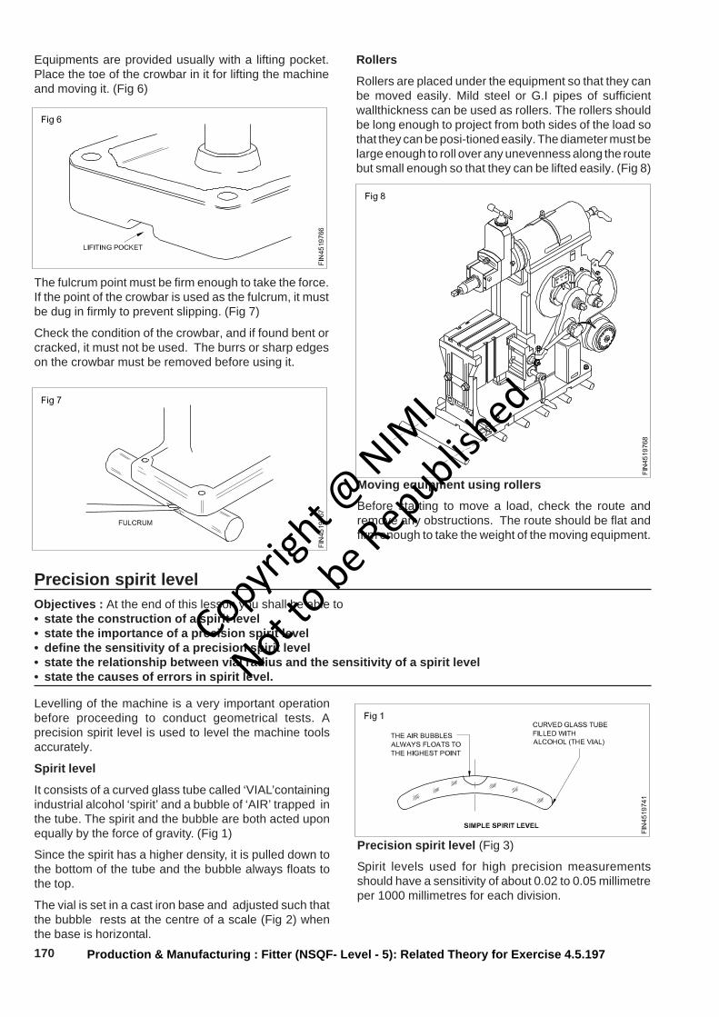
170
Equipments are provided usually with a lifting pocket.Place the toe of the crowbar in it for lifting the machineand moving it. (Fig 6)
The fulcrum point must be firm enough to take the force.If the point of the crowbar is used as the fulcrum, it mustbe dug in firmly to prevent slipping. (Fig 7)
Check the condition of the crowbar, and if found bent orcracked, it must not be used. The burrs or sharp edgeson the crowbar must be removed before using it.
Rollers
Rollers are placed under the equipment so that they canbe moved easily. Mild steel or G.I pipes of sufficientwallthickness can be used as rollers. The rollers shouldbe long enough to project from both sides of the load sothat they can be posi-tioned easily. The diameter must belarge enough to roll over any unevenness along the routebut small enough so that they can be lifted easily. (Fig 8)
Precision spirit levelObjectives : At the end of this lesson you shall be able to• state the construction of a spirit level• state the importance of a precision spirit level• define the sensitivity of a precision spirit level• state the relationship between vial radius and the sensitivity of a spirit level• state the causes of errors in spirit level.
Levelling of the machine is a very important operationbefore proceeding to conduct geometrical tests. Aprecision spirit level is used to level the machine toolsaccurately.
Spirit level
It consists of a curved glass tube called ‘VIAL’containingindustrial alcohol ‘spirit’ and a bubble of ‘AIR’ trapped inthe tube. The spirit and the bubble are both acted uponequally by the force of gravity. (Fig 1)
Since the spirit has a higher density, it is pulled down tothe bottom of the tube and the bubble always floats tothe top.
The vial is set in a cast iron base and adjusted such thatthe bubble rests at the centre of a scale (Fig 2) whenthe base is horizontal.
Precision spirit level (Fig 3)
Spirit levels used for high precision measurementsshould have a sensitivity of about 0.02 to 0.05 millimetreper 1000 millimetres for each division.
Production & Manufacturing : Fitter (NSQF- Level - 5): Related Theory for Exercise 4.5.197
Moving equipment using rollers
Before starting to move a load, check the route andremove any obstructions. The route should be flat andfirm enough to take the weight of the moving equipment.
Copyrigh
t @ NIM
I
Not to be Republish
ed
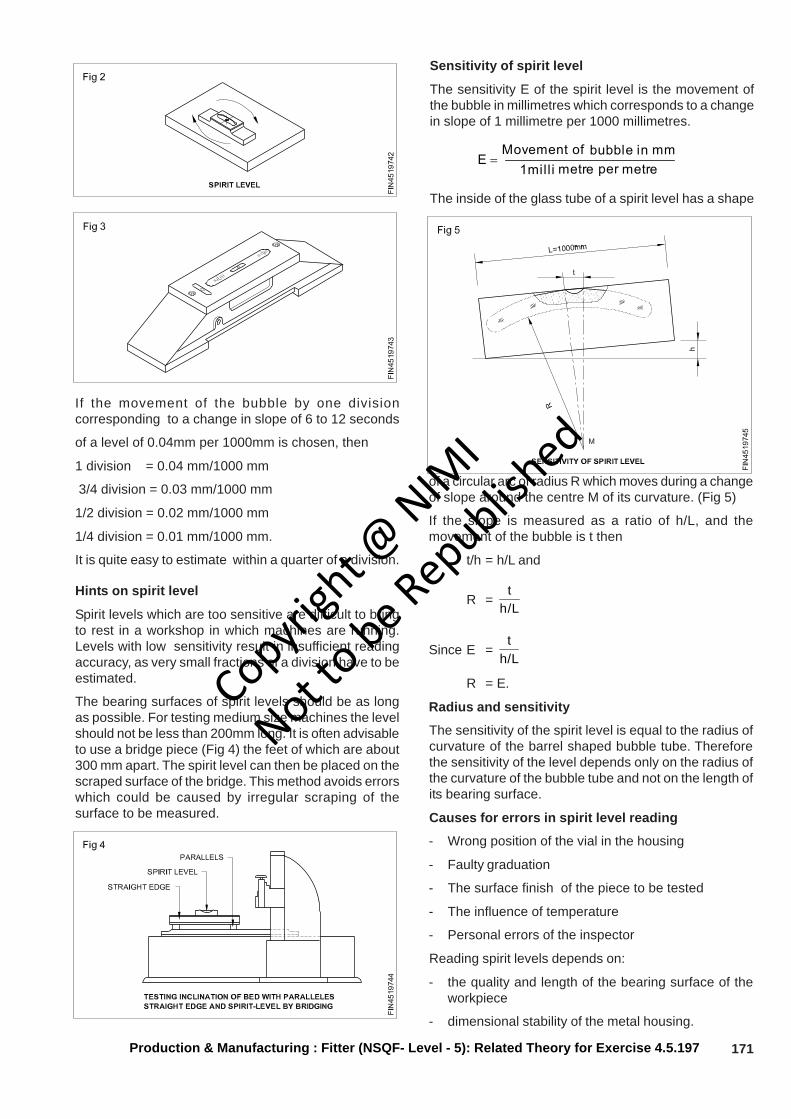
171
If the movement of the bubble by one divisioncorresponding to a change in slope of 6 to 12 seconds
of a level of 0.04mm per 1000mm is chosen, then
1 division = 0.04 mm/1000 mm
3/4 division = 0.03 mm/1000 mm
1/2 division = 0.02 mm/1000 mm
1/4 division = 0.01 mm/1000 mm.
It is quite easy to estimate within a quarter of a division.
Hints on spirit level
Spirit levels which are too sensitive are difficult to bringto rest in a workshop in which machines are running.Levels with low sensitivity result in insufficient readingaccuracy, as very small fractions of a division have to beestimated.
The bearing surfaces of spirit levels should be as longas possible. For testing medium size machines the levelshould not be less than 200mm long. It is often advisableto use a bridge piece (Fig 4) the feet of which are about300 mm apart. The spirit level can then be placed on thescraped surface of the bridge. This method avoids errorswhich could be caused by irregular scraping of thesurface to be measured.
Sensitivity of spirit level
The sensitivity E of the spirit level is the movement ofthe bubble in millimetres which corresponds to a changein slope of 1 millimetre per 1000 millimetres.
metre per metre 1mill imm in bubble of Movement
E =
The inside of the glass tube of a spirit level has a shape
of a circular arc of radius R which moves during a changeof slope around the centre M of its curvature. (Fig 5)
If the slope is measured as a ratio of h/L, and themovement of the bubble is t then
t/h = h/L and
R =L/h
t
Since E =L/h
t
R = E.
Radius and sensitivity
The sensitivity of the spirit level is equal to the radius ofcurvature of the barrel shaped bubble tube. Thereforethe sensitivity of the level depends only on the radius ofthe curvature of the bubble tube and not on the length ofits bearing surface.
Causes for errors in spirit level reading
- Wrong position of the vial in the housing
- Faulty graduation
- The surface finish of the piece to be tested
- The influence of temperature
- Personal errors of the inspector
Reading spirit levels depends on:
- the quality and length of the bearing surface of theworkpiece
- dimensional stability of the metal housing.
Production & Manufacturing : Fitter (NSQF- Level - 5): Related Theory for Exercise 4.5.197
Copyrigh
t @ NIM
I
Not to be Republish
ed
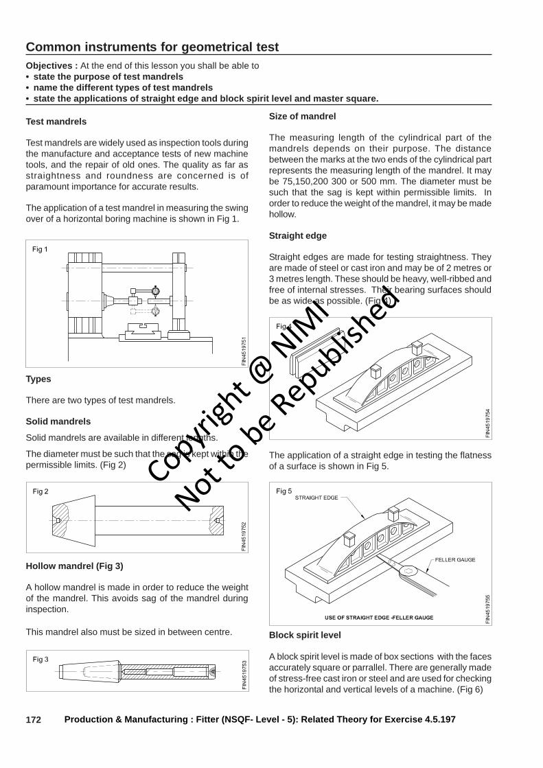
172
Common instruments for geometrical testObjectives : At the end of this lesson you shall be able to• state the purpose of test mandrels• name the different types of test mandrels• state the applications of straight edge and block spirit level and master square.
Test mandrels
Test mandrels are widely used as inspection tools duringthe manufacture and acceptance tests of new machinetools, and the repair of old ones. The quality as far asstraightness and roundness are concerned is ofparamount importance for accurate results.
The application of a test mandrel in measuring the swingover of a horizontal boring machine is shown in Fig 1.
Types
There are two types of test mandrels.
Solid mandrels
Solid mandrels are available in different lengths.
The diameter must be such that the sag is kept within thepermissible limits. (Fig 2)
Hollow mandrel (Fig 3)
A hollow mandrel is made in order to reduce the weightof the mandrel. This avoids sag of the mandrel duringinspection.
This mandrel also must be sized in between centre.
Size of mandrel
The measuring length of the cylindrical part of themandrels depends on their purpose. The distancebetween the marks at the two ends of the cylindrical partrepresents the measuring length of the mandrel. It maybe 75,150,200 300 or 500 mm. The diameter must besuch that the sag is kept within permissible limits. Inorder to reduce the weight of the mandrel, it may be madehollow.
Straight edge
Straight edges are made for testing straightness. Theyare made of steel or cast iron and may be of 2 metres or3 metres length. These should be heavy, well-ribbed andfree of internal stresses. Their bearing surfaces shouldbe as wide as possible. (Fig 4)
The application of a straight edge in testing the flatnessof a surface is shown in Fig 5.
Block spirit level
A block spirit level is made of box sections with the facesaccurately square or parrallel. There are generally madeof stress-free cast iron or steel and are used for checkingthe horizontal and vertical levels of a machine. (Fig 6)
Production & Manufacturing : Fitter (NSQF- Level - 5): Related Theory for Exercise 4.5.197
Copyrigh
t @ NIM
I
Not to be Republish
ed
173
The application of a block spirit level in testing a drillingmachine is shown in Fig 7.
RopesObjectives : At the end of this lesson you shall be able to• name the different types of ropes and their uses• state the precautions to be observed while using ropes• state the general inspection points for using ropes.
Ropes are made from individual fibres, spun togetherlike string or yarn. Hemp, cotton, Manila, steel andsynthetic wire are used in the manufacture of rope.Manila and hemp ropes are manufactured from the fibreof wild banana plants.
Ropes are manufactured in three or four strands. Manilaand hemp ropes are used for light duty hoisting with arope pulley block.
The following precautions should be observed whileusing the ropes.
- Avoid running the rope over sharp edges.
- Ropes should be kept dry because moisture hastenstheir decay.
- Hang wet rope loosely in an area where it can drybefore it is used.
- Avoid dragging of rope over concrete, gravel and otherrough surfaces.
- Frozen rope should not be used until it is thawed.
Wire ropes
Wire ropes or cables are built up of strands of wire laidtogether in the direction of opposite twists which form therope. Standard wire rope is made from strandsencompassing a single core.
Wire ropes are used for heavy duty hoisting
When the wires and strands are twisted in the samedirection the rope is known as ‘Lang lay rope’ (Fig 1) andwhen twisted in the opposite direction it is known asregular lay rope. (Fig 2) The combined lay rope is showninFig 3.
Rope inspection
- Inspect ropes frequently for damage.
- Surface inspection will reveal broken or worn outstrands.
- For interior inspection twist the rope in the oppositedirection to the way it was spun.
This will open up and separate the strands so that theinterior fibres can be examined.
Production & Manufacturing : Fitter (NSQF- Level - 5): Related Theory for Exercise 4.5.197
Copyrigh
t @ NIM
I
Not to be Republish
ed
174
Wooden block
The position of the foundation is first determined, markedoff and wooden pegs are driven if it is in the soil. (Fig 1)
The size of excavation is drawn with chalk if it is on aconcrete floor.
Excavating the hole should be done as neatly as possiblebut should the soil persist in falling into the hole it may beadvisable to shore this up by the use of shuttering. Theexcavation should be made a few millimetres deeper thanthe required foundation depth. The bottom surface is wellrammed prior to and after placing a layer of clean bottomingstones or broken bricks.
Wooden template
A wooden template is formed as shown in Fig 2 torepresent the base of the machine and to support boltsover the excavation as shown. The combined thicknessof the template frame A and blocks B should equal thethickness of the foot of the machine as shown. Theseboxes are formed of light timber and are suitably nailed foreasy removal later.
Wooden forms
Wooden forms for concrete foundations are made andplaced over the excavation.
Bracing the wooden form
After placing the wooden form in position in the excavation,it is firmly braced from the outside so as to withstand thepressure of the concrete and prevent any movementwhen the concrete is being poured.
Concrete
Should be prepared from clean cement on a woodensurface. Proportions for the mixture vary. A goodaverage mixture is 1:2:4. ie 1 part cement, 2 parts sandand 4 parts stone. This is mixed thrice when dry andthrice after wetting and is immediatelty placed on theexcavated area after a good spraying with water on theexcavated area.
The foundation should be given a day atleast to setbefore the template is removed.
Pulley blockObjectives : At the end of this lesson you shall be able to• describe of pulley block• use of pulley block.
Pulley block (Fig 1)
Pulley block is a system of two or more pulleys with a ropeor cable threaded between them, usually used to lift heavyloads. The pulleys are assembled together to form blocks
and then blocks are paired so that one is fixed and onemoves with the load. The rope is threaded through thepulleys to provide mechanical advantage that amplifiesthe force applied to the rope.
Production & Manufacturing : Fitter (NSQF- Level - 5): Related Theory for Exercise 4.5.197
Copyrigh
t @ NIM
I
Not to be Republish
ed
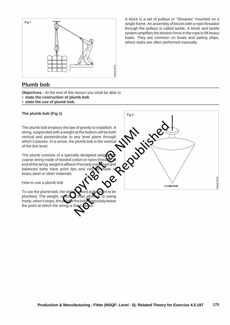
175
A block is a set of pulleys or “Sheaves” mounted on asingle frame. An assembly of blocks with a rope threadedthrough the pulleys is called tackle. A block and tacklesystem amplifies the tension force in the rope to lift heavyloads. They are common on boats and sailing ships,where tasks are often performed manually.
Plumb bobObjectives : At the end of this lesson you shall be able to• state the costruction of plumb bob• state the use of plumb bob.
The plumb bob (Fig 1)
The plumb bob employs the law of gravity to establish. Astring, suspended with a weight at the bottom will be bothvertical and perpendicular to any level plane throughwhich it passes. In a sense, the plumb bob is the verticalof the line level.
The plumb consists of a specially designed weight andcoarse string made of twisted cotton or nylon threads. Atend of the string weight is affixed.Precisely machined andbalanced bobs have point tips and can be made ofbrass,steel or other materials
How to use a plumb bob
To use the plumb bob, the string is fixed at the point to beplumbed. The weight, or bob, is than allowed, to swingfreely, when it stops, the point of the bob is precisely belowthe point at which the string is fixed above.
Production & Manufacturing : Fitter (NSQF- Level - 5): Related Theory for Exercise 4.5.197
Copyrigh
t @ NIM
I
Not to be Republish
ed

176
Production & Manufacturing Related Theory for Exercise 4.5.198Fitter - Errection and Testing
Sling load for shiftingObjectives: At the end of this lesson you shall be able to• state different type of slinging arrangement• state the common types of chain sling• mention different types of fastening bolts,hooks, lifting clamps etc.• illustrate various method of slinging practice• define rigging and various rigs and fittings.
Slinging is an important skill in lifting and shifting load inindustrial practices.
Slings are made with fibre rope, (manila, sisal,nylon,terylene and polypropylene) chain, wire rope etc. Otherappliances like hooks, eye bolts, shackles, lifting clampsetc are used to make or sling considering the type of theload.
Chain sling
Chain links are fabricated by welding from carbon oralloyed steel. Links are formed to the shape and weldedtogether to form a chain.
Chain slings are of different types, namely
- Single leg chain (Fig 1)
- Double leg chain (Fig 2)
- Four leg chain (Fig 3)
- Endless chain (Fig 4)
A chain will have the following components (Fig 1)
- Master link.
- Intermediate link.
- Joining link.
- Chain hook.
Wire rope sling
Wire rope slings are made of steel wire rope to form eyethimble mechanically spliced which accommodates amaster ring on one side and or plain eye look is knownas single legged sling (Fig 5a). Similarly, two legged,threel egged and four legged slings are shown in(Fig 5b,c and d) respectively.
Copyrigh
t @ NIM
I
Not to be Republish
ed
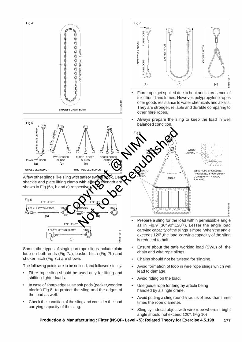
177
A few other slings like sling with safety swivel hook, Deeshackle and plate lifting clamp with effective length areshown in Fig (6a, b and c) respectively.
Some other types of single part rope slings include plainloop on both ends (Fig 7a), basket hitch (Fig 7b) andchoker hitch (Fig 7c) are shown.
The following points are to be noticed and followed strictly.
• Fibre rope sling should be used only for lifting andshifting lighter loads.
• In case of sharp edges use soft pads (packer,woodenblocks) Fig.8 to protect the sling and the edges ofthe load as well.
• Check the condition of the sling and consider the loadcarrying capacity of the sling.
• Fibre rope get spoiled due to heat and in presence oftoxic liquid and fumes. However, polypropylene ropesoffer goods resistance to water chemicals and alkalis.They are stronger, reliable and durable comparing toother fibre ropes.
• Always prepare the sling to keep the load in wellbalanced condition.
• Prepare a sling for the load within permissible angleas in Fig.9 (300,900,1200).). Lesser the angle loadcarrying capacity of the slings is more. When the angleexceeds 1200 ,the load carrying capacitiy of the slingis reduced to half.
• Ensure about the safe working load (SWL) of thechain and wire rope slings.
• Chains should not be twisted for slinging.
• Avoid formation of loop in wire rope slings which willlead to damage.
• Avoid riding on the load.
• Use guide rope for lengthy article beinghandled by a single crane.
• Avoid putting a sling round a radius of less than threetimes the rope diameter.
• Sling cylindrical object with wire rope wherein bightangle should not exceed 1200. (Fig 10)
Production & Manufacturing : Fitter (NSQF- Level - 5): Related Theory for Exercise 4.5.198
Copyrigh
t @ NIM
I
Not to be Republish
ed
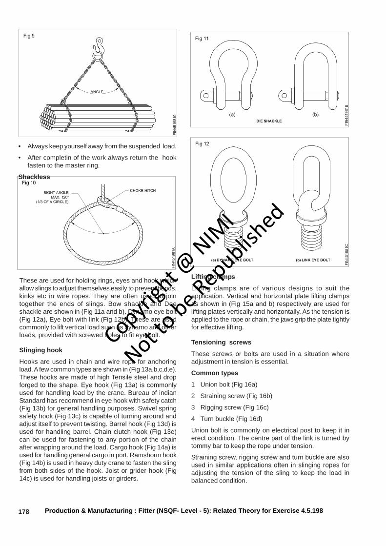
178
• Always keep yourself away from the suspended load.
• After completin of the work always return the hookfasten to the master ring.
Shackless
Production & Manufacturing : Fitter (NSQF- Level - 5): Related Theory for Exercise 4.5.198
These are used for holding rings, eyes and hook whichallow slings to adjust themselves easily to prevent bends,kinks etc in wire ropes. They are often used to jointogether the ends of slings. Bow shackle and Deeshackle are shown in (Fig 11a and b). Dynamo eye bolt(Fig 12a), Eye bolt with link (Fig 12b). These are usedcommonly to lift vertical load such as dynamo and otherloads, provided with screwed holes to fit eye bolt.
Slinging hook
Hooks are used in chain and wire rope for anchoringload. A few common types are shown in (Fig 13a,b,c,d,e).These hooks are made of high Tensile steel and dropforged to the shape. Eye hook (Fig 13a) is commonlyused for handling load by the crane. Bureau of indianStandard has recommend in eye hook with safety catch(Fig 13b) for general handling purposes. Swivel springsafety hook (Fig 13c) is capable of turning around andadjust itself to prevent twisting. Barrel hook (Fig 13d) isused for handling barrel. Chain clutch hook (Fig 13e)can be used for fastening to any portion of the chainafter wrapping around the load. Cargo hook (Fig 14a) isused for handling general cargo in port. Ramshorm hook(Fig 14b) is used in heavy duty crane to fasten the slingfrom both sides of the hook. Joist or grider hook (Fig14c) is used for handling joists or girders.
Lifting clamps
Lifting clamps are of various designs to suit theapplication. Vertical and horizontal plate lifting clampsas shown in (Fig 15a and b) respectively are used forlifting plates vertically and horizontally. As the tension isapplied to the rope or chain, the jaws grip the plate tightlyfor effective lifting.
Tensioning screws
These screws or bolts are used in a situation whereadjustment in tension is essential.
Common types
1 Union bolt (Fig 16a)
2 Straining screw (Fig 16b)
3 Rigging screw (Fig 16c)
4 Turn buckle (Fig 16d)
Union bolt is commonly on electrical post to keep it inerect condition. The centre part of the link is turned bytommy bar to keep the rope under tension.
Straining screw, rigging screw and turn buckle are alsoused in similar applications often in slinging ropes foradjusting the tension of the sling to keep the load inbalanced condition.
Copyrigh
t @ NIM
I
Not to be Republish
ed
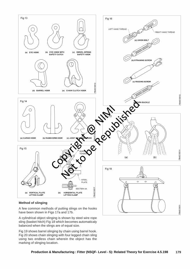
179Production & Manufacturing : Fitter (NSQF- Level - 5): Related Theory for Exercise 4.5.198
Method of slinging
A few common methods of putting slings on the hookshave been shown in Figs 17a and 17b.
A cylindrical object slinging is shown by steel wire ropesling (basket hitch) Fig 18 which becomes automaticalybalanced when the slings are of equal size.
Fig 19 shows barrel slinging by chain using barrel hook.Fig 20 shows chain slinging with four legged chain slingusing two endless chain wherein the object has themarking of slinging location.
Copyrigh
t @ NIM
I
Not to be Republish
ed

180 Production & Manufacturing : Fitter (NSQF- Level - 5): Related Theory for Exercise 4.5.198
Slinging methods
Wooden casing arrives at the purchaser’s premises withsling marks as shown in Fig 21.The casing should beunpacked and suitable slings are made to shift to theplace of installation.
Such shifting is done commonly by fibre rope slings forlighter machines and comparatively heavier machinesare shifted using suitable wire rope and chain slings.Suitable packings are to be used for protecting finishedsurfaces of the machineries.
A few mehtod of slinging shaper, lathe, radial drillingmachine, vertical milling and universal cylindrical grinderare shown in Fig 21 respectively.
Rigging Theory
Rigging is the action of designing and installing theequipment, in the preparation to move objects. A teamof riggers design and install the lifting or rolling equipmentneeded to raise, roll, slide or lift objects such as with acrane or block and tackle.
Rigging is the equipment such as wire rope. turnbuckles,clevis, jacks used with cranes and other lifting equipment(Fig 22) in material handling and structure relocation.Rigging systems commonly include shackles, masterlinks and slings. Also, lifting bags in under water lifting.
Copyrigh
t @ NIM
I
Not to be Republish
ed
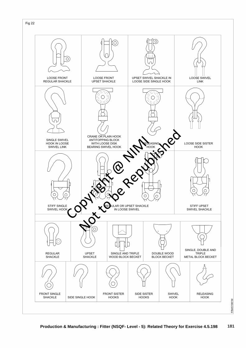
181Production & Manufacturing : Fitter (NSQF- Level - 5): Related Theory for Exercise 4.5.198
Copyrigh
t @ NIM
I
Not to be Republish
ed
182 Production & Manufacturing : Fitter (NSQF- Level - 5): Related Theory for Exercise 4.5.198
Fork lift and pallet truckObjectives: At the end of this lesson you shall be able to• tell about fork lift (stacker)• mention handling load by hand pallet truck• state advantages of moving load by stracker and pallet truck.
The fork lift is a small 4-wheel vehicle with diesel/petrol/electrically powered engine. Heavy counter weight arefitted to the rear of the units. There are two lifting fork orarms in front of the machine which are adjustable to carrythe load. They are available in various designs andcapacities for shifting and stacking load in differentpositions.
Types
1) Diesel automotive fork lifter.
2) Battery powered fork lift stacker.
3) Hydraulic stacker.
4) Mechanical stacker.
5) Hand pallet truck.
1 Diesel automotive fork lifter (Fig 1)
This diesel powered truck is driven by a driver to carryloads to considerable distances to and from the shopfloor/yards to work place or for storage capacity 2 tonneto 10 tonne lift 2 meter height (common).
Fork unit can be hydraulically fitted, upto 15 degreesinward or outward and lifted to desired level. (Fig 1a)
This works very efficiently to move loads faster even onrough roads. Suitably used in harbour work,in industries,ware houses. transportation between lorry and railwayterminals etc.
Maintenance
- Engine oil and hydraulic oils are to be changedperiodically.
- Check for leakage in hydraulic cylinders.
- Cleaning and lubrication should be done to all motionparts including counter weight chain.
2 Battery powered fork lift stacker (Fig 2)
Powered fork lift stackers are compact in design andused to carry load mainly indoor within narrow space forshifting and stacking even to higher levels. The operatorwalks beside the truck to steer it. Lifting is donehydraulically.
They are commonly used in workshops, warehouse ,rail containers, wagons etc. capacity 500 kg-2000 kg.Lift upto 5 meter commonly used.
Maintenance
- All motion parts are to be cleaned and lubricatedperiodically
- Hydraulic oil should be changed (Servo System 57/68 as recommended) once in two years.
- Oil seals are to be changed in case of leakage.
- Distilled water should be poured in the battery as andwhen the level goes down.
- Battery should be charged periodically.
3 Manually operated hydraulic stacker (Fig 3)
This type of stacker is used commonly as they arecheaper and can be easily handled manually for shiftingand stacking load in a limited space.
Capacity- 500 Kg to 2000 Kg.
Lift upto 5 meter.
Copyrigh
t @ NIM
I
Not to be Republish
ed
183Production & Manufacturing : Fitter (NSQF- Level - 5): Related Theory for Exercise 4.5.198
Beneficially used in light industries, ware house etc forloading, unloading and stacking.
Maintenance
- Clean and lubricate all motion parts.
- Change hydraulic oil once in two years (servosystem57or 68 as recommended to be used)
- Replace oil seal for oil leakage.
Mechanical stacker (Fig 4)
This type of stacker is mechanically handled for moving,lifting and stacking load. These can be operated in alimited space so they are used in small scale industries.
Capacity 500 Kg.
Lift upto 2 meter.
Maintenance
- Clean and lubricate all motion parts periodically.
Hand pallete truck (Fig 5)
Pallet trucks are basically used for carrying pallet bins(Fig 5a) and other loads on floors, warehouses wiht highrate of turn over even bulky goods.
Capacity 500 kg to 2000 kg.
Maintenance
- Change hydraulic oil once in two years (servosystemoil 57 or 68 as recommended). Topup oil periodicallywherever required.
- Replace oil seals in case of oil leakage.
- Clean and lubricate other motion parts periodically.
Types of cranesObjectives: At the end of this lesson you shall be able to• State basic function of crane• mention the types of crane• describe the application of various cranes• state the highlights on troubleshooting• narrate the safety on overhead crane repair.
Copyrigh
t @ NIM
I
Not to be Republish
ed
184 Production & Manufacturing : Fitter (NSQF- Level - 5): Related Theory for Exercise 4.5.198
Basic function of crane
Crane is made up of sturdy structural member of steel,which are used in Industries, Port trust etc to shift theheavy materials from one place to another place forsubsequent operation, assembly etc. The shape and itsconstruction varies with application and types. There aremany types of cranes are available.
Types
- Floor cranes- Jib cranes- Derrick cranes- Overhead cranes- Gantry cranes- Travelling cranes.
Floor cranes (Fig 1a & b)
Hand operated floor cranes are used for handling lightloads (up to 2000 Kg.) on the shop floor.
Hydraulic floor cranes are also used for lifting and shiftingloads. The boom of the crane is moved up and downapproximately 300 hydraulically. The boom can beextended to work for a longer reach. As the boom extendsthe loads carrying capacity decreases. Capacity rangesfrom 1000 Kg to 5000 Kg.
These floor cranes are mounted on wheels and can bemoved from one place to another by pushing.
Fig 2 shows simple jib crane mounted on the strong baseand supported by bearing plate at the top. The jib alsocalled boom is supported by vertical mast with guysupport at the front and stiff legs at the rear.
There are three possible movements of load ie.
a Raise or lower the load
b Horizontal movement of load between mast andend of boom
c 3600 rotation of mast on its axis (slewing).
Pillar jib crane
Fig 3 show simple jib crane. The bottom is fastened tothe mast about two-thirds of the way from the base. Therear end of the boom extends beyond the mast. Boom issupported by guys from the top of the mast to provideadditonal support. The lifting tackle on the boom hangsfrom a trolley-mounted block, which slides along thelength of the boom to shift the load at any position. Theload can be rotated within a radius from mast.
Fig 4 shows the bracket jib crane used for light load.
Derricks cranes
Gin pole derrick crane (Fig 5)
Gin pole derrick one single pole units with one end firmlysecured at the base to prevent movement. It is used asa temporary hoist to raise and lower a number of lightloads. In setting up a gin pole, use atleast two after guysto provide support for the working end of the pole.
Guyed derrick crane (Fig 6)
The derricks are made of steel or wood. Derrick madeof steel are mostly used. The derrick or boom issupported with mast. Mast and boom are either handoperated or power operated. The boom is rotate through
Copyrigh
t @ NIM
I
Not to be Republish
ed
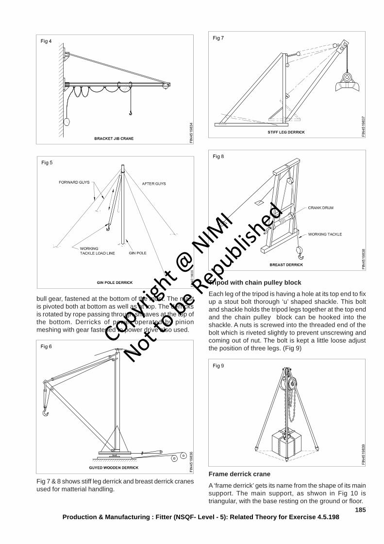
185Production & Manufacturing : Fitter (NSQF- Level - 5): Related Theory for Exercise 4.5.198
bull gear, fastened at the bottom of the most. The mastis pivoted both at bottom as well as at top. The derricksis rotated by rope passing through sheaves at the top ofthe bottom. Derricks of power operated by pinionmeshing with gear fastened to power drive also used.
Fig 7 & 8 shows stiff leg derrick and breast derrick cranesused for matterial handling.
Tripod with chain pulley block
Each leg of the tripod is having a hole at its top end to fixup a stout bolt thorough ‘u’ shaped shackle. This boltand shackle holds the tripod legs together at the top endand the chain pulley block can be hooked into theshackle. A nuts is screwed into the threaded end of thebolt which is riveted slightly to prevent unscrewing andcoming out of nut. The bolt is kept a little loose adjustthe position of three legs. (Fig 9)
Frame derrick crane
A ‘frame derrick’ gets its name from the shape of its mainsupport. The main support, as shwon in Fig 10 istriangular, with the base resting on the ground or floor.
Copyrigh
t @ NIM
I
Not to be Republish
ed
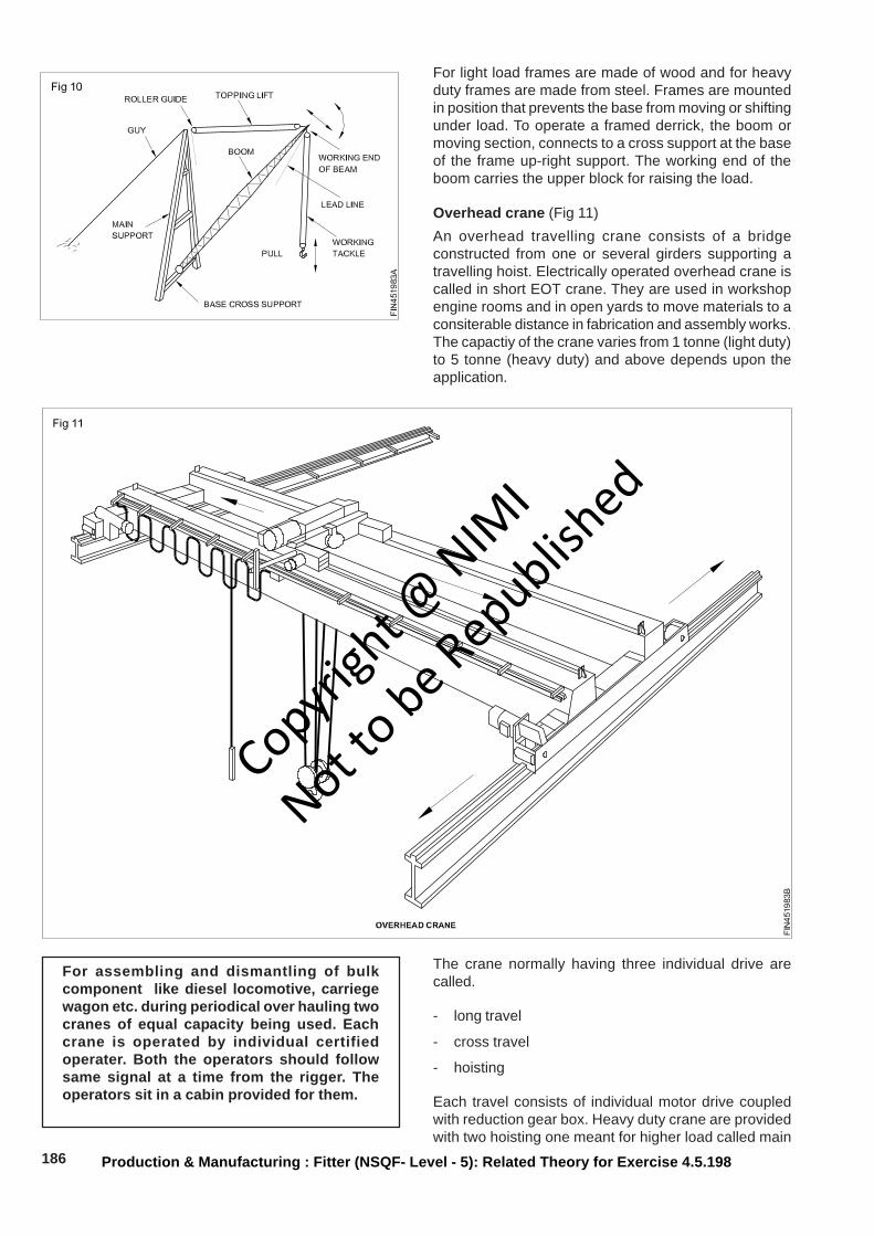
186 Production & Manufacturing : Fitter (NSQF- Level - 5): Related Theory for Exercise 4.5.198
For light load frames are made of wood and for heavyduty frames are made from steel. Frames are mountedin position that prevents the base from moving or shiftingunder load. To operate a framed derrick, the boom ormoving section, connects to a cross support at the baseof the frame up-right support. The working end of theboom carries the upper block for raising the load.
Overhead crane (Fig 11)An overhead travelling crane consists of a bridgeconstructed from one or several girders supporting atravelling hoist. Electrically operated overhead crane iscalled in short EOT crane. They are used in workshopengine rooms and in open yards to move materials to aconsiterable distance in fabrication and assembly works.The capactiy of the crane varies from 1 tonne (light duty)to 5 tonne (heavy duty) and above depends upon theapplication.
For assembling and dismantling of bulkcomponent like diesel locomotive, carriegewagon etc. during periodical over hauling twocranes of equal capacity being used. Eachcrane is operated by individual certifiedoperater. Both the operators should followsame signal at a time from the rigger. Theoperators sit in a cabin provided for them.
The crane normally having three individual drive arecalled.
- long travel
- cross travel
- hoisting
Each travel consists of individual motor drive coupledwith reduction gear box. Heavy duty crane are providedwith two hoisting one meant for higher load called main
Copyrigh
t @ NIM
I
Not to be Republish
ed

187Production & Manufacturing : Fitter (NSQF- Level - 5): Related Theory for Exercise 4.5.198
hoist and another one for light load called auxiliary hoist.The capactiy of the crane is written on the structuralmember of the crane visibly is called safe working load(SWL).
While lifting the load by crane the load do notexceed safe working load of a crane at anycircumtances.
They are standard signals that every crane operatorshould follow while handling the load to control the crane.
While lifting load by using chain having morethan one legs, ensure all the legs should haveequal length.
While lifting load the structural member of thecrane subjected to deflection from its position.The permissible deflection is 1mm for each 900mm span measured at midpoint of the spanby keeping the load at the centre. A cranehaving 9 meters span i.e. distance between tworails of long travel, the permissible deflectionis 10mm.
Travelling wall crane also used in assembly shop. Thelong travel wheels runs on rails mounted on wheels.Fig 12 shows travelling wall crane.
Gantry crane (Fig 13)
Most gantry cranes are much larger than over headtravelling cranes. It is used outside of the buildings.Gantry cranes also move on tracks,but their tracks areon the ground rather than sudpended overhead. Trolleysare mounted on two upright structures separated by theconnecting bridge.
Trolley wheels support the gantry. The gantry’s loadmovement capabilities are the same as those of thetravelling crane.
Trucks mounted mobile crane (Fig 14)
There are locomotive cranes, truck-mounted craneswhich are also used for lifting and moving the loads.
These crane can be used in remote places.
Problem - ”The crane is not working when switched on”.
When attending any repair on the overheadcrane wear helmet and safety belt. The safetybelt to be tied with structural member whileattending repair to avoid accident by slipping.
Precautions in the removal and replacement of heavyparts
People who install or dismantle machinery andequipment could:
• Work in isolation
• Work on machinery and equipment at heights, or overmachinery and equipment to connect services, suchas electricity, air or water
• Work in low light, or with bright directional light
• access machinery and equipment from the top, sidesor underneath
• Work with or near craness, forklifts or rigging to liftmachinery and equipment
• work in confined spaces
• use power tools, welders, extension leads, whichpresent electrical hazards if damaged or wet.
Copyrigh
t @ NIM
I
Not to be Republish
ed
188 Production & Manufacturing : Fitter (NSQF- Level - 5): Related Theory for Exercise 4.5.198
People operating machinery and equipment could:
• be required to place their hands close to themechanism of the machinery and equipment thatdoes the work, and may be injured if caught or trappedby moving parts
• be exposed to constant harmful noise, radiated,energy or fumes being emitted form the machineryand equipement being operated, or are close to
• inadvertently bump or knock poorly placed controllevers or buttons
• be required to make adjustments to the mechanismof machinery and equipment while the machine is inmotion
• be required to clear away scrap
• make minor adjusments, or reach into the movingmechanism of the machinery and equipment beingoperated.
People providing maintenance or repair servicescould:
• work alone
• work on machinery and equipment at height, or overmachinery and equipment to connect services, suchas electricity, air or water
• access machinery and equipment from the rear orsides
• be required to enter confined spaces of largermachiery and equipment
• be trapped by the mechanism of the machinery andequipment through poor isolation of energy sourcesor stored energy, such as spring-loaded or counter-balance mechanisms, compressed air or fluids, orparts held in position by hydraulics or pneumatic (air)rams
• Move heavy parts when changing the set up ofmachinery and equipment, or repairing failed parts,such as electric motors or gear box assemblies
• disable or remove normal safety systems to accessthe mechanisms of machinery and equipment.
People providing cleaning services could:
• work alone
• access machinery and equipment from the rear orsides, or in unexpected ways
• climb on machinery and equipment
• enter confined spaces, or larger machinery andequipment
• become trapped by the mechanism of the machineryand equipment through poor isolation of energysources or stored energy, such as spring - loaded orcounter - balance mechanisms, compressed air orfluids, or parts held in position by hydraulics orpneumatic (air) rams
• work with chemicals
• operate electrical equipment in wet areas.
Copyrigh
t @ NIM
I
Not to be Republish
ed