Embed Size (px)
Citation preview

SECTIONALSECTIONAL
ORTHOGRAPHIC
PROJECTIONSPROJECTIONS
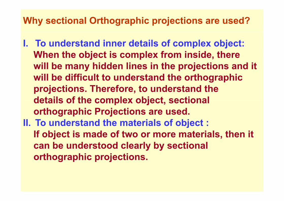
Why sectional Orthographic projections are used?
I. To understand inner details of complex object:When the object is complex from inside thereWhen the object is complex from inside, therewill be many hidden lines in the projections and it will be difficult to understand the orthographicwill be difficult to understand the orthographicprojections. Therefore, to understand the details of the complex object sectionaldetails of the complex object, sectional orthographic Projections are used.
II To understand the materials of object :II. To understand the materials of object : If object is made of two or more materials, then it can be understood clearly by sectionalcan be understood clearly by sectional orthographic projections.
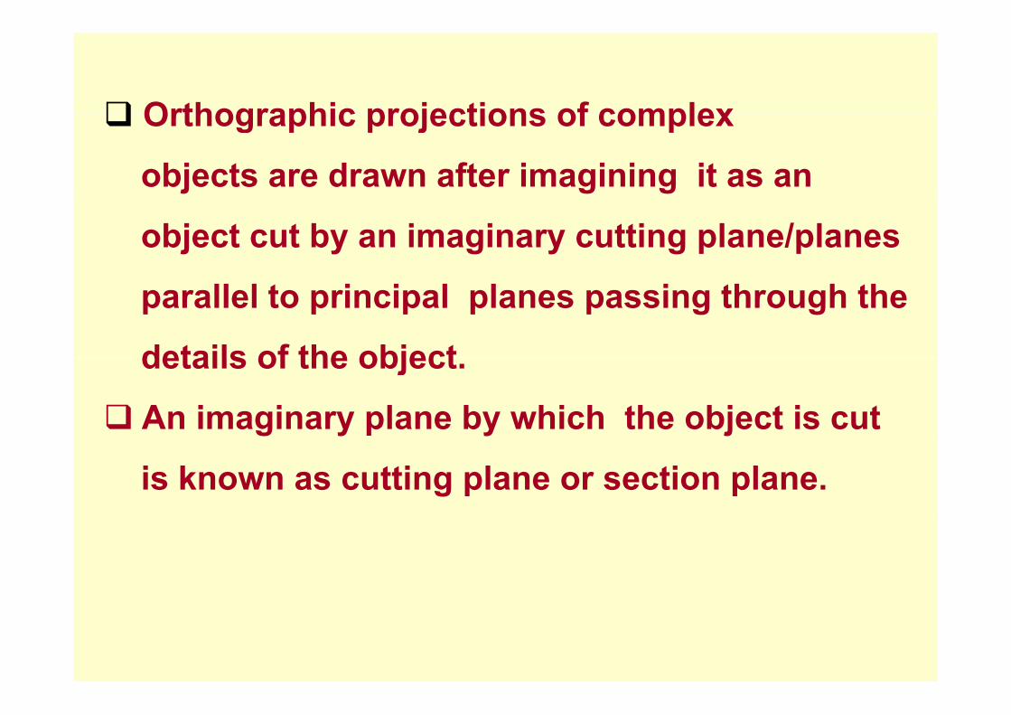
Orthographic projections of complexOrthographic projections of complex
objects are drawn after imagining it as an
object cut by an imaginary cutting plane/planes
parallel to principal planes passing through the
details of the objectdetails of the object.
An imaginary plane by which the object is cut
is known as cutting plane or section plane.
P ti f th bj t b t tti lPortion of the object between cutting plane
and observer is imagined to be removed and g
then the object is viewed by the observer and
projection is drawn.
P j ti f t bj t i kProjection of cut object is known as
sectional view or sectional projection.p j
Generally hidden lines are not drawn in
sectional view.
In sectional views, the Shape of the section,
visible edges and contours of object behindvisible edges and contours of object behind
the section plane are drawn.
When one view is drawn sectional, other views
are drawn as if the object is not cut and the
object exists as a wholeobject exists as a whole.
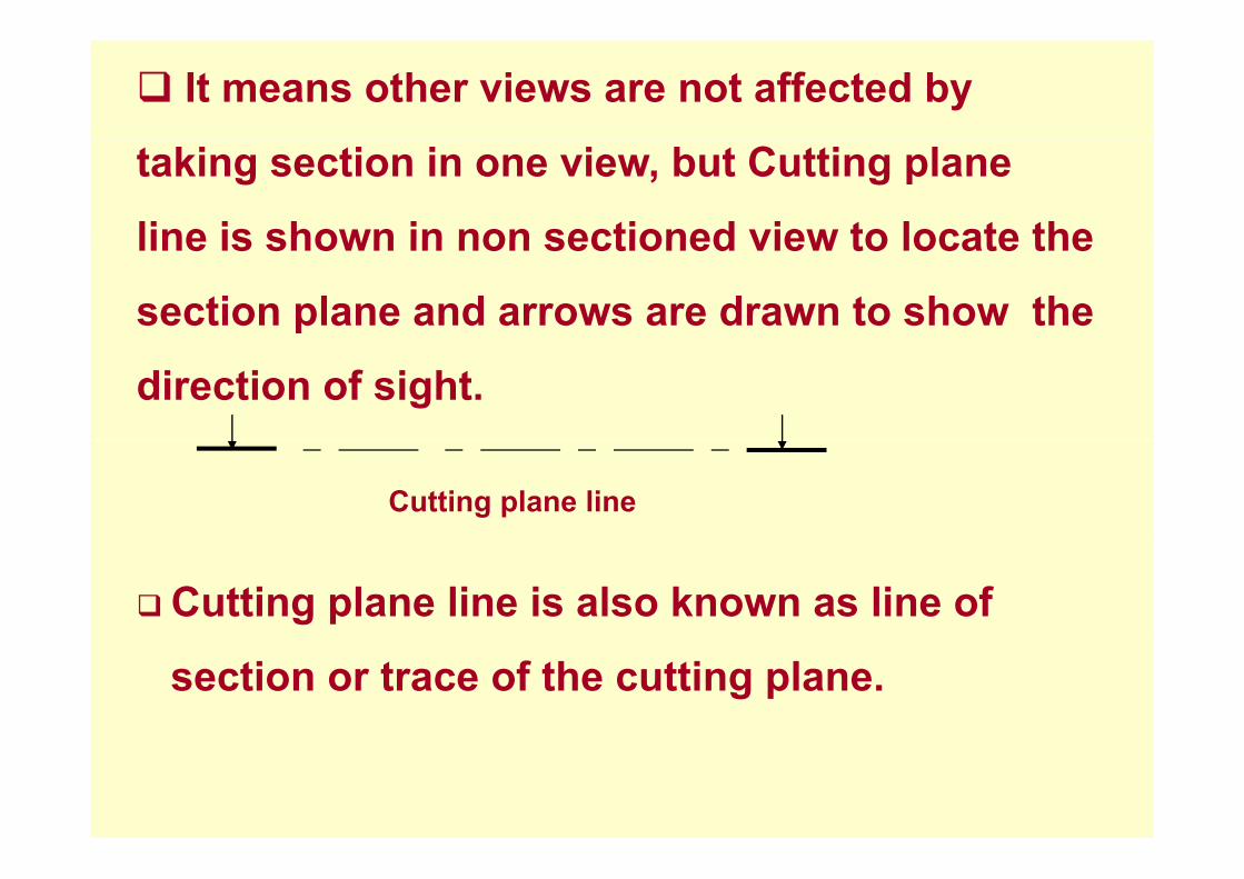
It means other views are not affected by
taking section in one view, but Cutting plane
line is shown in non sectioned view to locate theline is shown in non sectioned view to locate the
section plane and arrows are drawn to show the
direction of sight.
Cutting plane line
Cutting plane line is also known as line of
section or trace of the cutting plane.

The portion of the object cut by cutting plane and
touching the cutting plane is shown by
drawing hatching or section lines in them.
Hatching or section lines are drawn thinner thanHatching or section lines are drawn thinner than
object lines.
Normally hatching or section lines are drawn
at 45˚.
Hatching lines are evenly spaced at aboutHatching lines are evenly spaced at about
2 to 3 mm apart.

H t hiobserver
Cutting plane or section planeParallel to H.P
Hatching
Parallel to H.P.
Sectional T VSectional T.V.
X
Portion between observer and plane (Upper half portion)
i i i d t b d
F.V.
is imagined to be removed.
Sectioned portion will be as shown in fig.
BackTrue shape of sectioned portion will be
seen in T.V

Various cutting planes or section planes
Cutting plane Parallel to Principal vertical
plane.
C tti l P ll l t P i i l h i t lCutting plane Parallel to Principal horizontal
plane.plane.
Cutting plane Parallel to profile plane.
Cutting plane Parallel to Principal vertical planeCutting plane Parallel to Principal vertical plane
Wh bj t i t b l ll l tWhen an object is cut by a plane parallel to
Principal vertical plane then:p p
The real or true shape of the section is observed
in F.V.
Section plane ill be seen as a c tting plane lineSection plane will be seen as a cutting plane line
in T.V.
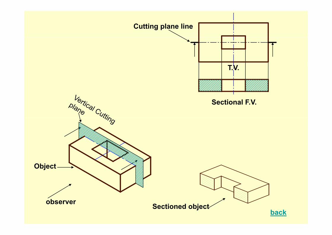
Cutting plane line
T.V.
Sectional F.V.
Object
observerback
Sectioned object
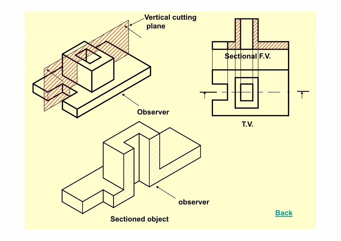
Vertical cuttingplane
Sectional F.V.
ObserverT.V.
observer
Sectioned object
observerBack

C tti l P ll l t P i i l h i t l lCutting plane Parallel to Principal horizontal plane
When an object is cut by a plane parallel to Principal j y p p p
horizontal plane then:
The real or true shape of the section is observed
i T Vin T.V.
Section plane will be seen as a cutting plane linep g p
in F.V.
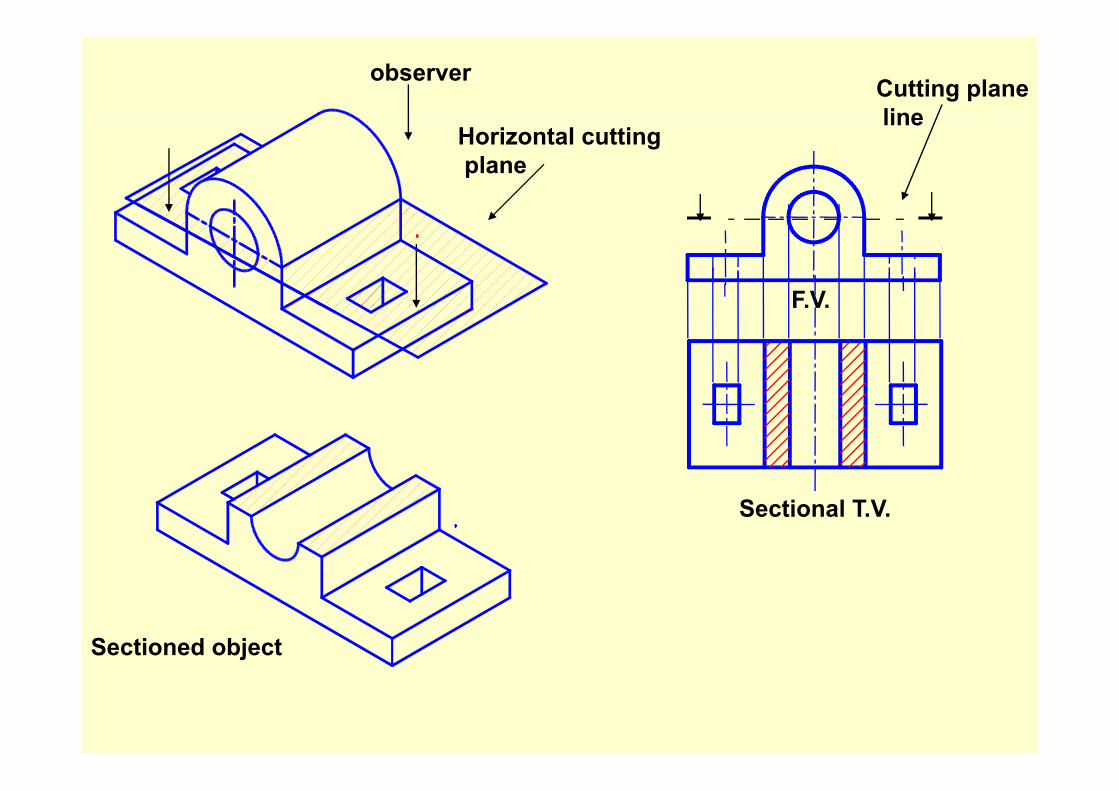
observer Cutting planeline
Horizontal cuttingplane
F.V.F.V.
Sectional T.V.
Sectioned object
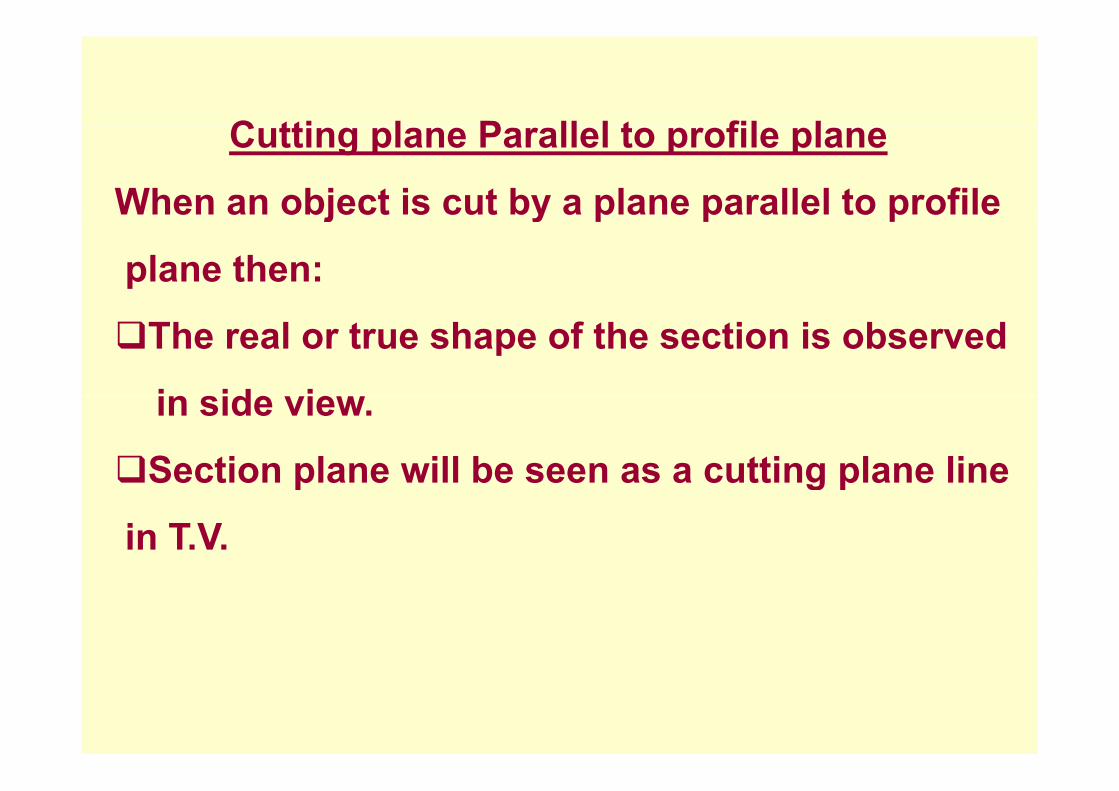
C tti l P ll l t fil lCutting plane Parallel to profile plane
When an object is cut by a plane parallel to profilej y p p p
plane then:
The real or true shape of the section is observed
i id iin side view.
Section plane will be seen as a cutting plane linep g p
in T.V.

A
A Sectioned object
X

Cutting plane line
Sectional R.H.S.V F.V.
A
T.V.X ASectioned object
Sectioning rule for machine elements like :Sectioning rule for machine elements like :
Ribs rivets webs shafts pins nuts boltsRibs, rivets, webs, shafts, pins, nuts, bolts, washers, keys and cotter.
Whenever, the cutting plane is passing through
above machine elements and if cutting plane
contains the axis of above machine elements,
then they are not sectioned.then they are not sectioned.
However, when the cutting plane is cutting,
Elements perpendicular to the axis of the
Above Machine elements, section is taken
and in the projection hatching lines are drawn.
If tti l d t i l d i thIf cutting plane does not include axis then
These elements are hatchedThese elements are hatched.

Sectioning of Rivets
CORRECT WRONG
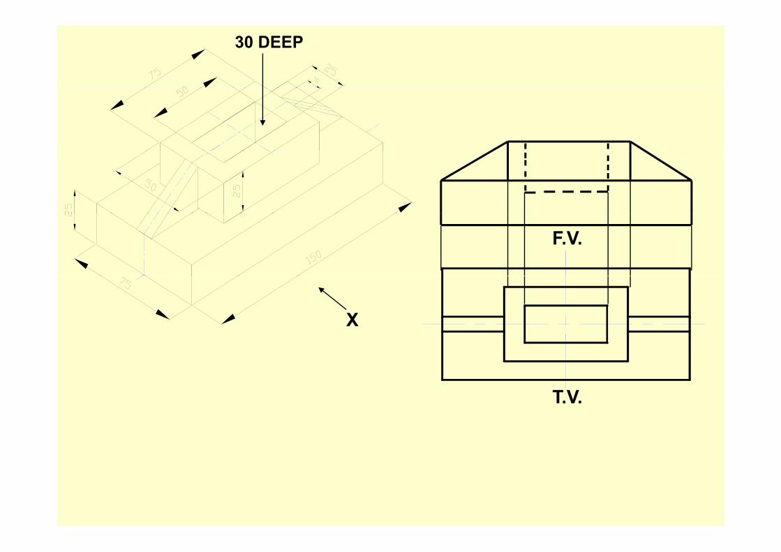
30 DEEP
F.V.
X
T.V.T.V.
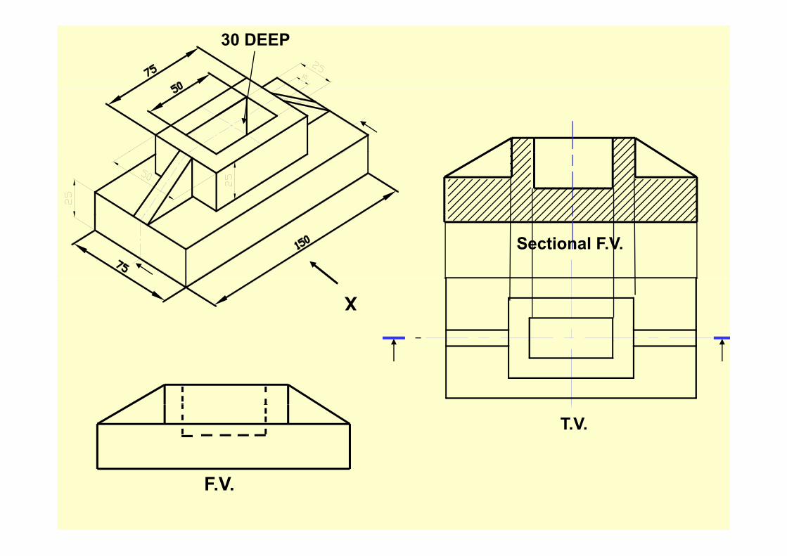
30 DEEP
Sectional F.V.X
T.V.
F.V.
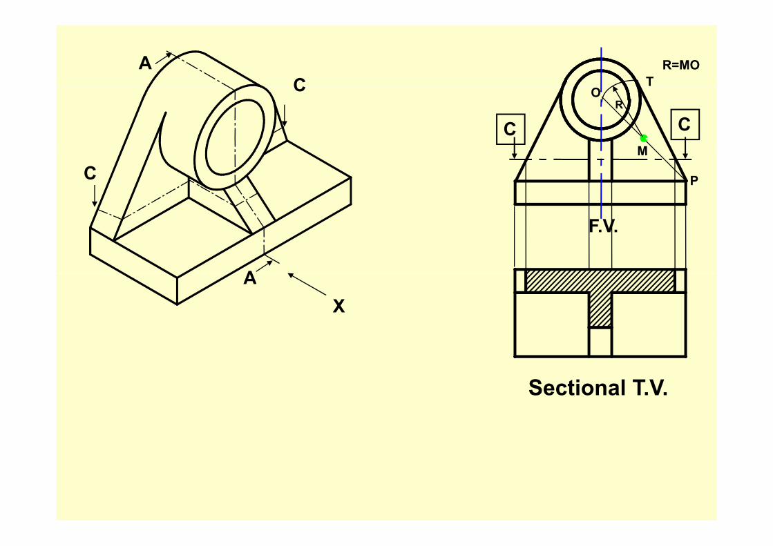
AC
R=MOTC
C CM
OR
CM
P
A
F.V.
XA
Sectional T.V.

O
R=MO
C CM
O
R
Rib MRib
F.V.Sectional L.H.S.V.A
C
C
XA
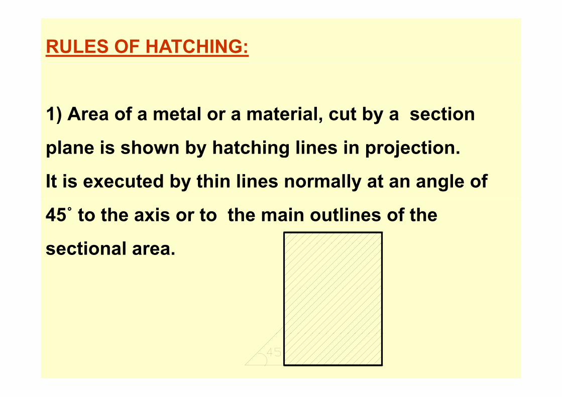
RULES OF HATCHING:
1) A f t l t i l t b ti1) Area of a metal or a material, cut by a section
plane is shown by hatching lines in projection.plane is shown by hatching lines in projection.
It is executed by thin lines normally at an angle of
45˚ to the axis or to the main outlines of the
ti lsectional area.

(2) If the axis of the boundary of section is at 45˚then(2) If the axis of the boundary of section is at 45 then the vertical or horizontal hatching lines are drawn.
Axis at 45˚
Axis at 45˚
(3) Separate area of a section of a single(3) Separate area of a section of a single component are hatched in the same mannermanner. CLICK FOR EXAMPLE
(4) Hatching lines on a second part, adjacent to the first are at an angle of 45˚adjacent to the first are at an angle of 45 but in the opposite direction. Hatching li thi d t dj t t fi t tlines on a third part adjacent to first two are drawn at an angle of 30˚ or 60˚. Sometimes spacing or pitch of the hatching lines is varied to separate it from g pthe adjacent parts.
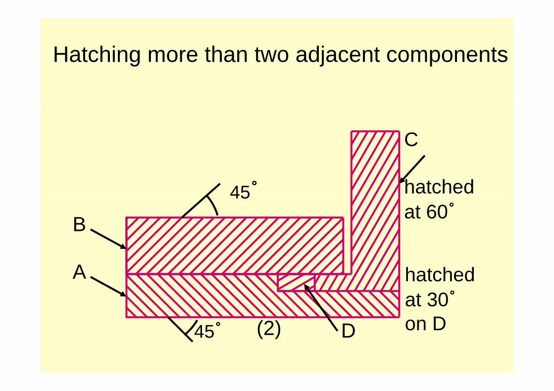
Hatching more than two adjacent components g j p
C
hatched45˚at 60˚B
45
A hatched
(2) D45˚at 30˚on D(2) D45 on D

(5) If hatching is required on a large section(5) If hatching is required on a large section
area, it is avoided. It is limited to a zone
following the contour of the sectioned area
required to be hatched.
Large area

(6) If hatching is required on a very thin section(6) If hatching is required on a very thin section
area, it is avoided. Complete section is shown
entirely black. Thin space is left between
adjacent section of the same type.
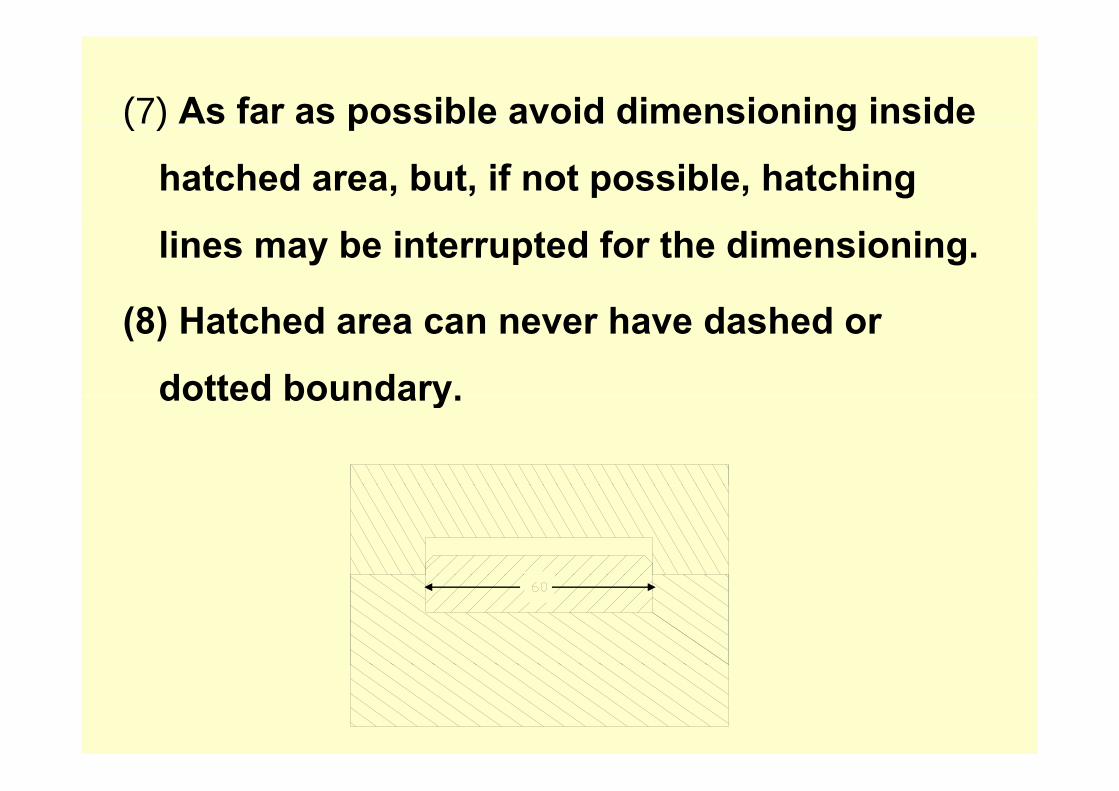
(7) As far as possible avoid dimensioning inside ( ) p g
hatched area, but, if not possible, hatching
lines may be interrupted for the dimensioning.
(8) Hatched area can never have dashed or
dotted boundary.dotted boundary.
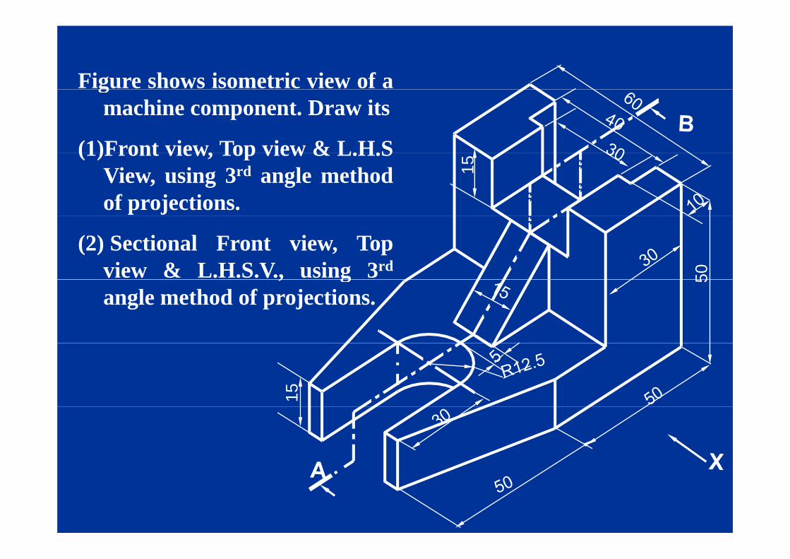
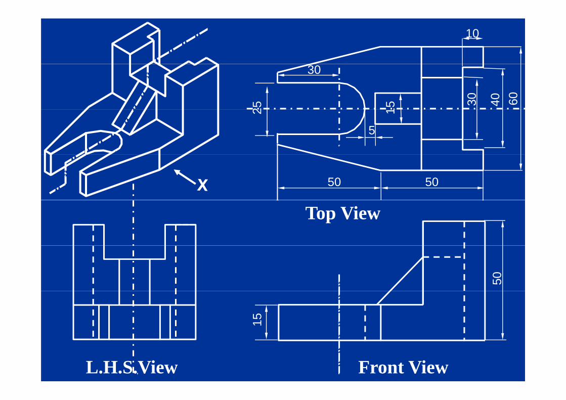
Figure shows isometric view of agmachine component. Draw its
(1)Front view, Top view & L.H.S
15
(1)Front view, Top view & L.H.SView, using 3rd angle methodof projections.
50
(2) Sectional Front view, Topview & L.H.S.V., using 3rd
5, gangle method of projections.
15
10
604030525
30
12
5
50 50
Top View
50
15
Front ViewL.H.S.View

B
It will be nearer to V.P.
R i d li f h
It will be nearer to V.P.in 1st angle method &against the vertical
A
Retained split of the machine parts
plane in 3rd anglemethod.

10
30
604030
1525
30
5A
50 50
Top View
AA
Sectional Front View -ABL.H.S. ViewB
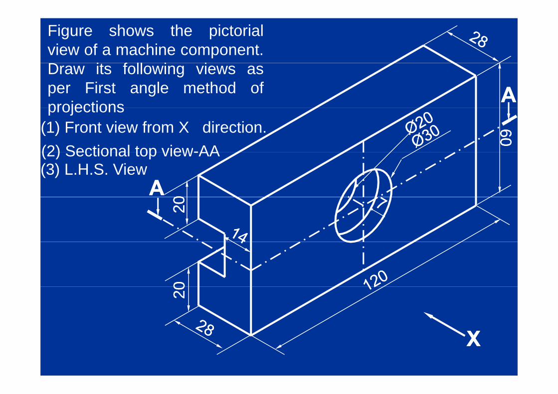
Figure shows the pictorialview of a machine component.D i f ll i i
AADraw its following views asper First angle method ofprojections
6060
projections(1) Front view from X direction.(2) Sectional top view-AA
00AA
(2) Sectional top view-AA(3) L.H.S. View
2020002020
XXXX
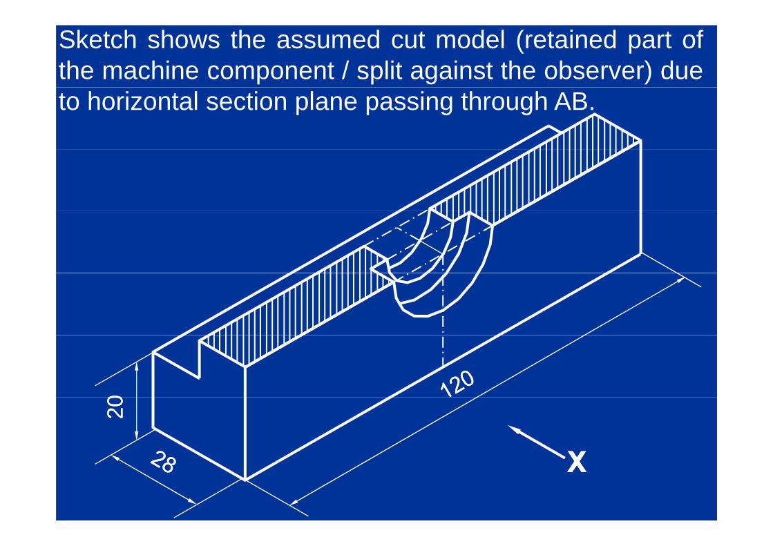
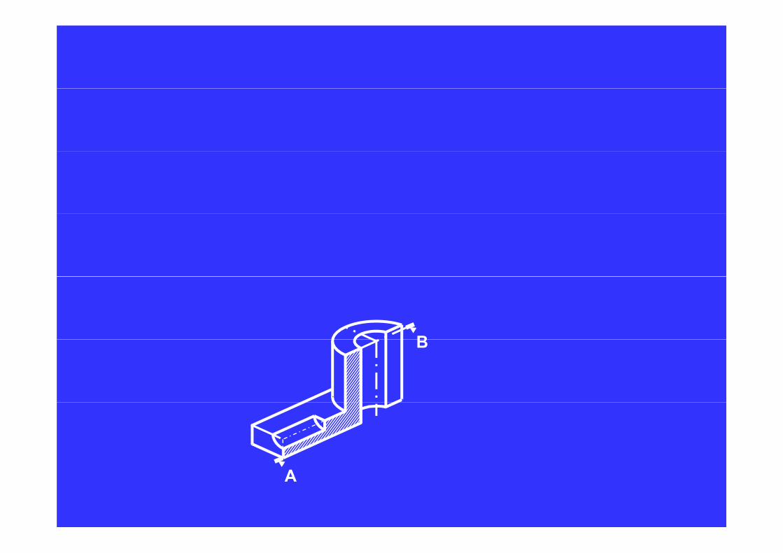
Sketch shows the assumed cut model (retained part ofthe machine component / split against the observer) dueto horizontal section plane passing through AB.
002020
XXXX

Ø30, 7deep Ø20Ø20
00AA6060
2020
AAAA
AA AA66
2020
120120F.V.F.V.
L.H.S.V.L.H.S.V.
28281414 AA
Sectional T.V.Sectional T.V.--AAAA
XX

φφ3030B
Figure shows the pictorial viewof a machine components.Draw its following views,using 3rd angle method ofprojectionsprojections.
(1) Front view from arrow X
6060
(2) Top View
(3) Sectional R H S V - AB(3) Sectional R.H.S.V - AB202022
XXA

Retained split, will benearer to VP in 1st
Bnearer to V.P. in 1st
angle method &against the verticalgplane in 3rd anglemethod.
No hatching inthis area as notcontained in thecontained in thesection plane
R i d li f h
A
Retained split of the machine parts

AAB
B
B
6060
9090
A
2020 2020
99
4040T V
XXA
44
AAT.V.
8080
S C
2020
AAF.V.
Full SEC.R.H.S.V

PROBLEM
Sketch, shows isometric view of a machine part.Draw itsDraw its (1) Full Sectional F.V. (sectional F.V.)
(2) T.V.
(3) R.H.S.V.U thi d l th d f th hiUse third angle method of orthographicprojection. Dimension the view as per thep j palign system.
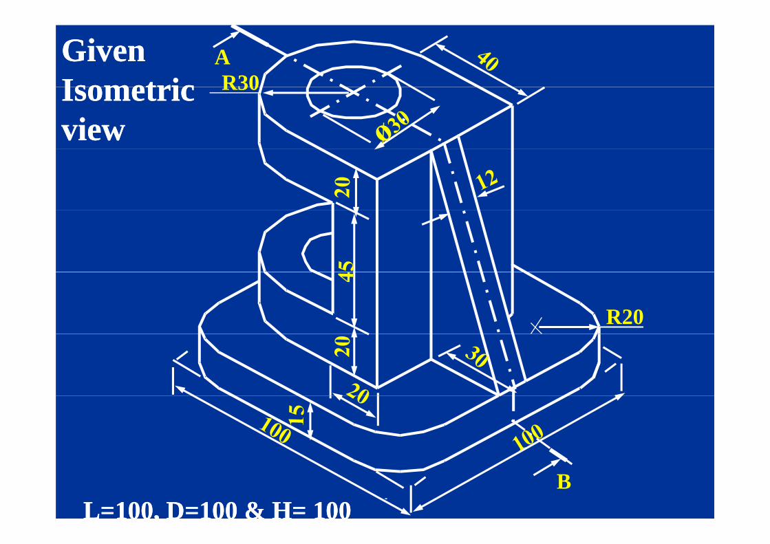
R30AGiven Given
IsometricIsometric R30Isometric Isometric viewview
R20
BL=100, D=100 & H= 100L=100, D=100 & H= 100
AR20
BBAA
30AA
TOP VIEWTOP VIEW60
B
12
60
45
100 12
R.H.S. VIEWR.H.S. VIEW
100BB
SEC. FRONT VIEWSEC. FRONT VIEW
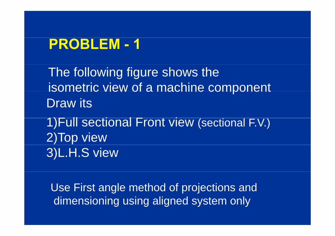
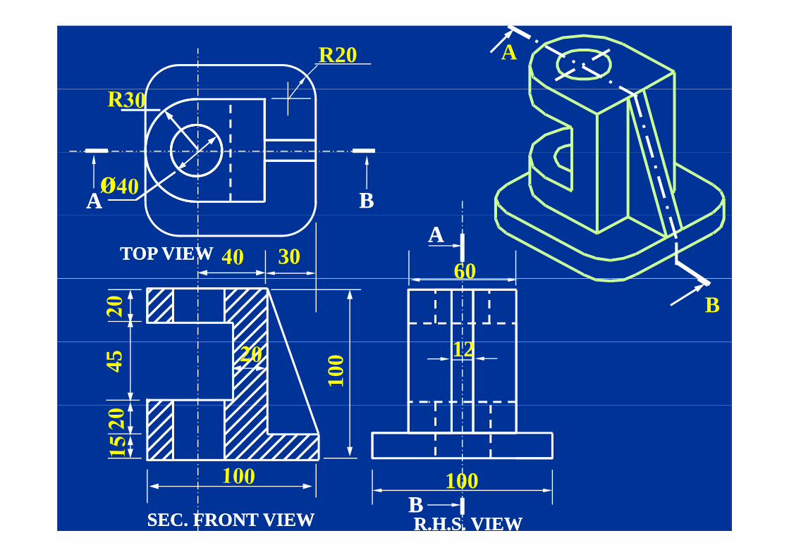
PROBLEM - 1
The following figure shows theisometric view of a machine componentisometric view of a machine componentDraw its1)F ll ti l F t i1)Full sectional Front view (sectional F.V.)2)Top view3)L.H.S view
Use First angle method of projections anddi i i i li d t ldimensioning using aligned system only

R 25R 25
Φ 25 ,10 deep
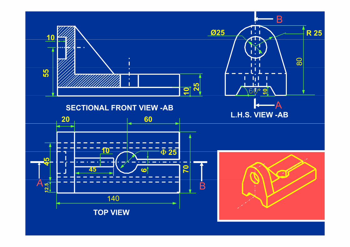
R 2510 Ø251055
25 60°10 10
20 60SECTIONAL FRONT VIEW -AB
L.H.S. VIEW -AB
Φ 2510
70
Φ 25
45
45
10
12.5
TOP VIEW

R 2510 Ø2510
55
25 6010 101
FRONT VIEW L.H.S. VIEW
20 60
70
Φ 25
45
45
10
12.5
TOP VIEW

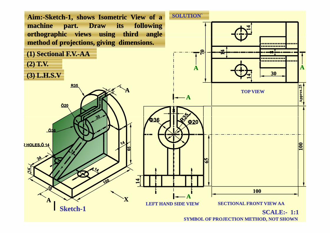
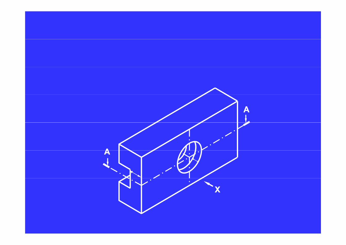
AimAim::--SketchSketch--11,, showsshows IsometricIsometric ViewView ofof aamachinemachine partpart.. DrawDraw itsits followingfollowingorthographicorthographic viewsviews usingusing thirdthird angleangle
SOLUTION`SOLUTION`
g pg p gg ggmethodmethod ofof projections,projections, givinggiving dimensionsdimensions..(1) Sectional F.V.(1) Sectional F.V.--AAAA(2) T V(2) T V(2) T.V.(2) T.V.(3) L.H.S.V(3) L.H.S.V
AA TOP VIEWTOP VIEWR35R35
AAAA3030
AA
88
AATOP VIEWTOP VIEW
Ö20Ö20
Φ20Φ20Φ36Φ36
ÖÖ
Ö36Ö36
002 HOLES,Ö 142 HOLES,Ö 14
6565
4`4`
100
100
AA
1414
AA AALEFT HAND SIDE VIEWLEFT HAND SIDE VIEW SECTIONAL FRONT VIEW AASECTIONAL FRONT VIEW AA
XX
SCALE:SCALE:-- 1:11:1SYMBOL OF PROJECTION METHOD, NOT SHOWNSYMBOL OF PROJECTION METHOD, NOT SHOWN
SketchSketch--11

SOLUTION`SOLUTION`Aim:Aim:--SketchSketch--1, shows Isometric View of a 1, shows Isometric View of a machine part. Draw its following machine part. Draw its following
th hi i i thi d lth hi i i thi d lorthographic views using third angle orthographic views using third angle method of projections, giving dimensions.method of projections, giving dimensions.(1) Sectional F.V.(1) Sectional F.V.--AAAA(2) T.V.(2) T.V.
SCALE:SCALE:-- 1:11:1
AAAA
R35R35
( )( )(3) L.H.S.V(3) L.H.S.V
3030
AATOP VIEWTOP VIEW
SCALE:SCALE: 1:11:1
88Φ20Φ20
R35R35AA
1414
88
Φ20Φ20Φ36Φ36Φ36Φ36
100
1002 HOLES,Ö 142 HOLES,Ö 14
AALEFT HAND SIDE VIEWLEFT HAND SIDE VIEW SECTIONAL FRONT VIEW AASECTIONAL FRONT VIEW AA
SYMBOL OF PROJECTION METHOD, NOT SHOWNSYMBOL OF PROJECTION METHOD, NOT SHOWN
XXAA

Types of sectional view
(1) Full sectional View ( )
(2) Half sectional View .
(1) Full section:
The sectional view obtained after removing oneThe sectional view obtained after removing one
half portion of the object through its centre line p j g
by an imaginary cutting plane is known as full
sectional view.

If it happens to be elevation (front view),If it happens to be elevation (front view),
it is known as Full sectional elevation or
Full sectional front view. Normally the word
‘f ll’ i itt d‘full’ is omitted.
If it happens to be plan (top view), it is knownIf it happens to be plan (top view), it is known
as full Sectional plan or full sectional top view.
Similarly there can be full sectional side view.
N ll th d ‘f ll’ i itt dNormally the word ‘full’ is omitted.
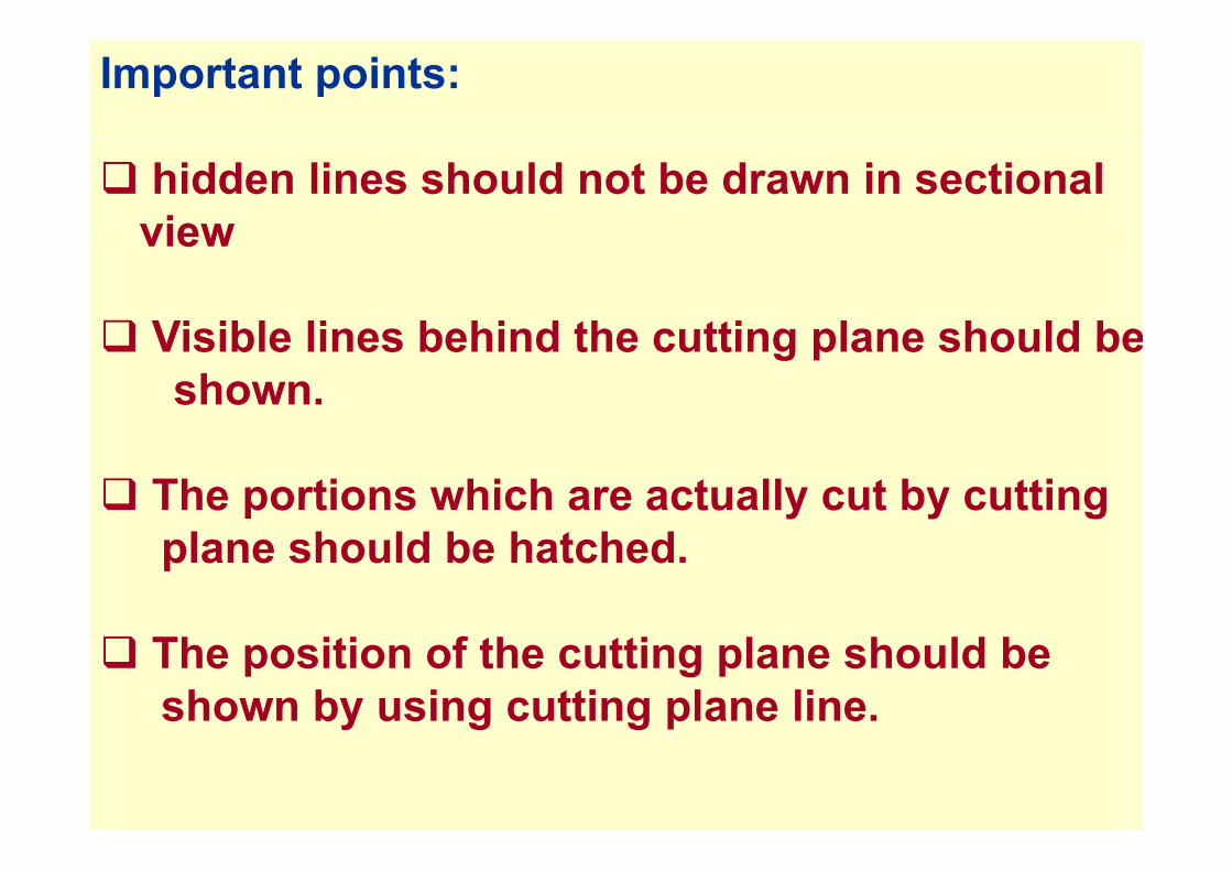
Important points:
hidden lines should not be drawn in sectional viewview
Visible lines behind the cutting plane should beVisible lines behind the cutting plane should beshown.
The portions which are actually cut by cutting l h ld b h t h dplane should be hatched.
The position of the cutting plane should be shown by using cutting plane line.

SPECIALSECTIONSSECTIONS
HALF SECTIONHALF SECTION
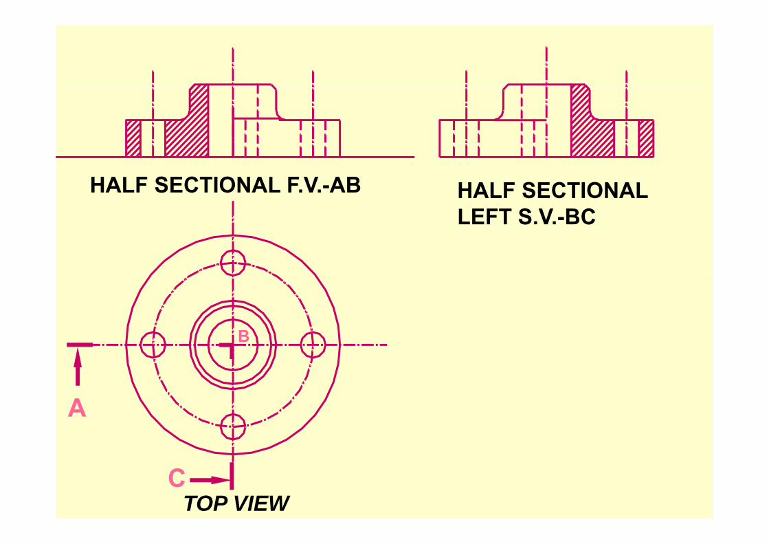
HALF SECTIONAL F.V.-AB HALF SECTIONALLEFT S V BCLEFT S.V.-BC
BB
A
CTOP VIEW
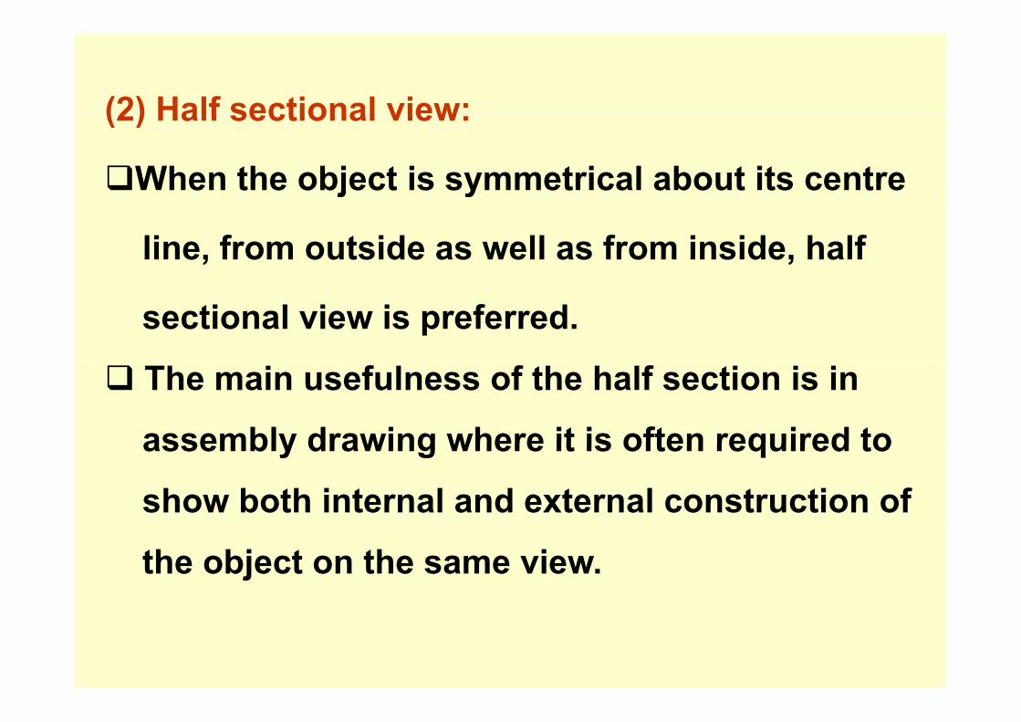
(2) Half sectional view:(2) Half sectional view:
When the object is symmetrical about its centrej y
line, from outside as well as from inside, half
sectional view is preferred.
The main usefulness of the half section is in
assembly drawing where it is often required toassembly drawing where it is often required to
show both internal and external construction of
the object on the same view.
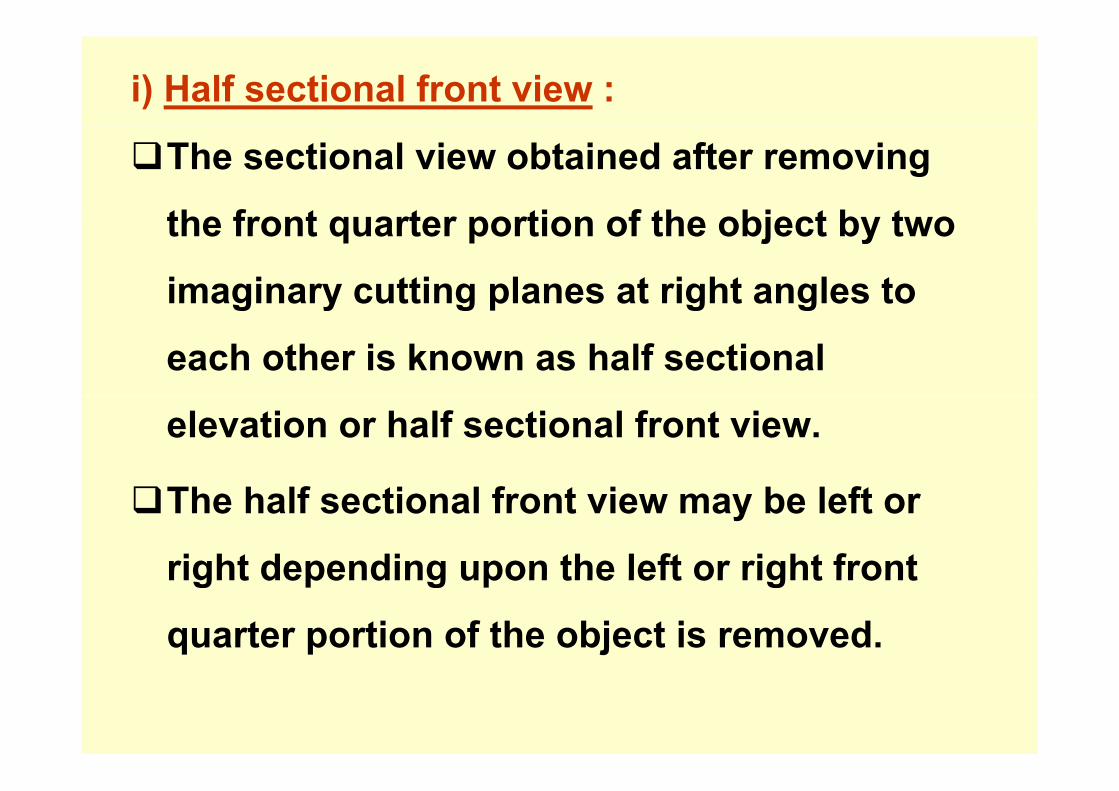
i) Half sectional front view :
The sectional view obtained after removing
th f t t ti f th bj t b tthe front quarter portion of the object by two
imaginary cutting planes at right angles to g y g p g g
each other is known as half sectional
elevation or half sectional front view.
The half sectional front view may be left or
right depending upon the left or right frontright depending upon the left or right front
quarter portion of the object is removed.

ii) Half sectional top view:
sectional top view. The sectional view
bt i d ft i th t t tiobtained after removing the top quarter portion
of the object by two imaginary cutting planes atof the object by two imaginary cutting planes at
right angles to each other is known as half
sectional plan or half
Th h lf ti l t i b l ft i htThe half sectional top view may be left or right
depending upon the left or right top quarterdepending upon the left or right top quarter
portion of the object is removed.
Similarly there can be half sectional side view.

OFFSETOFFSET S C OSECTION
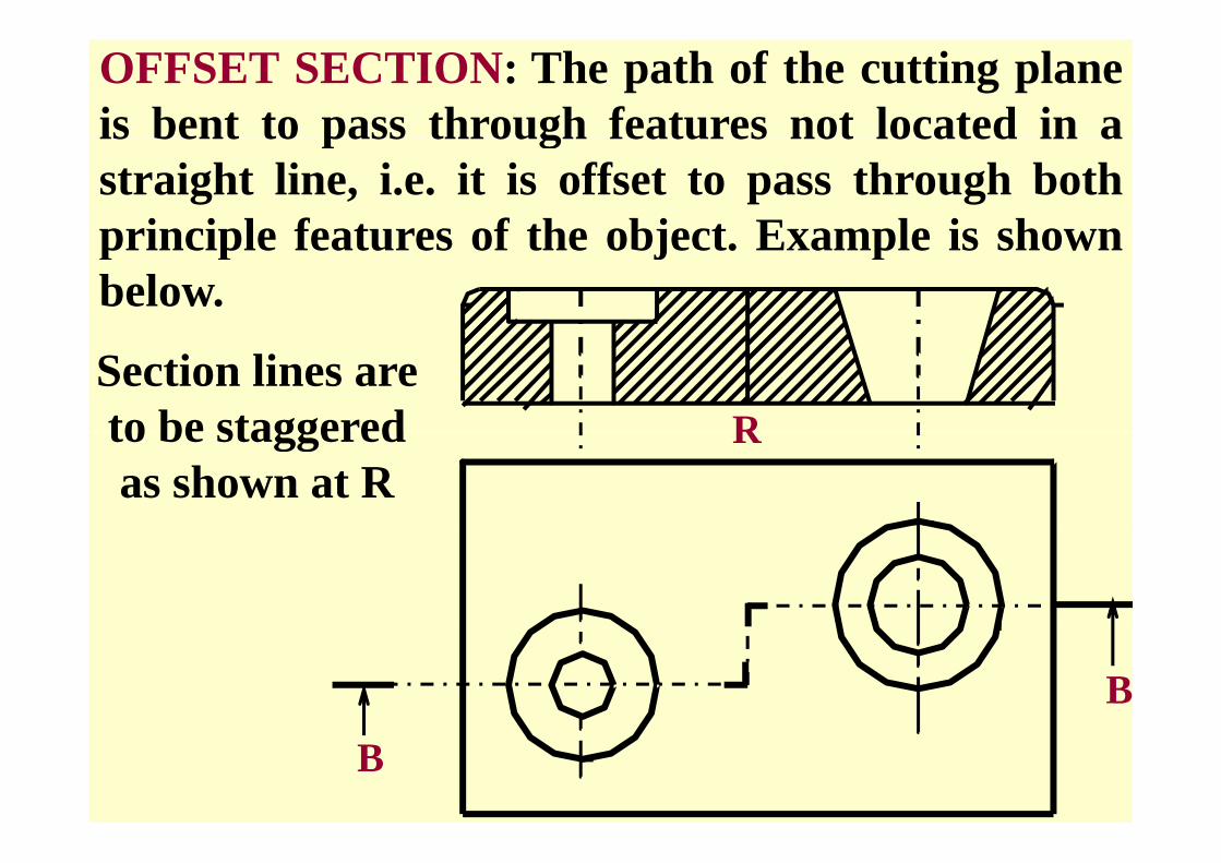
OFFSET SECTION: The path of the cutting planeis bent to pass through features not located in ais bent to pass through features not located in astraight line, i.e. it is offset to pass through bothprinciple features of the object Example is shownprinciple features of the object. Example is shownbelow.
Section lines are to be staggered Rto be staggered as shown at R
R
B
B

SPECIAL SECTIONSSPECIAL SECTIONS
REMOVED &REVOLVED SECTIONS

REVOLVEDSECTIONSECTION
REMOVED SECTION
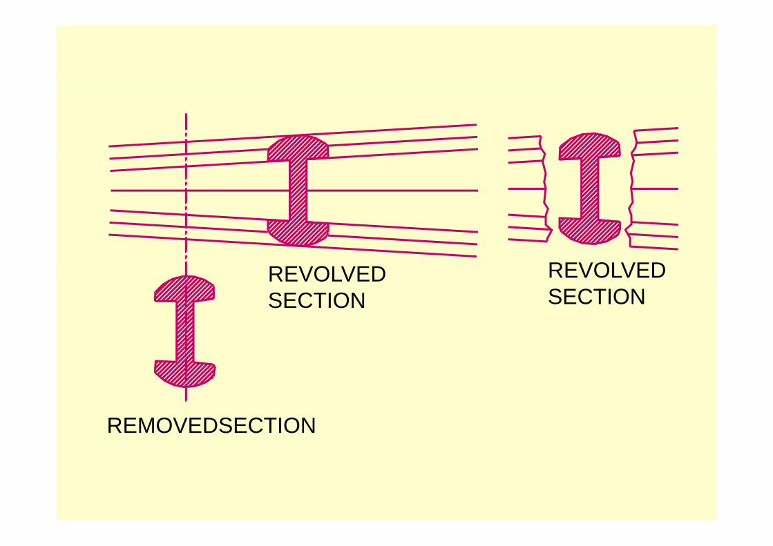
REVOLVED REVOLVEDREVOLVEDSECTION
REVOLVEDSECTION
REMOVEDSECTION

REVOLVED SECTION

REMOVED SECTION

REMOVED SECTIONS
Partial (broken localPartial (broken, local or Zonal) Sectionor Zonal) Section.

Partial (broken, local or Zonal) Section.
This is used to show only a desired features of thebj t N tti l li dobject . No cutting plane lines are necessary, and
it shown by wavy line
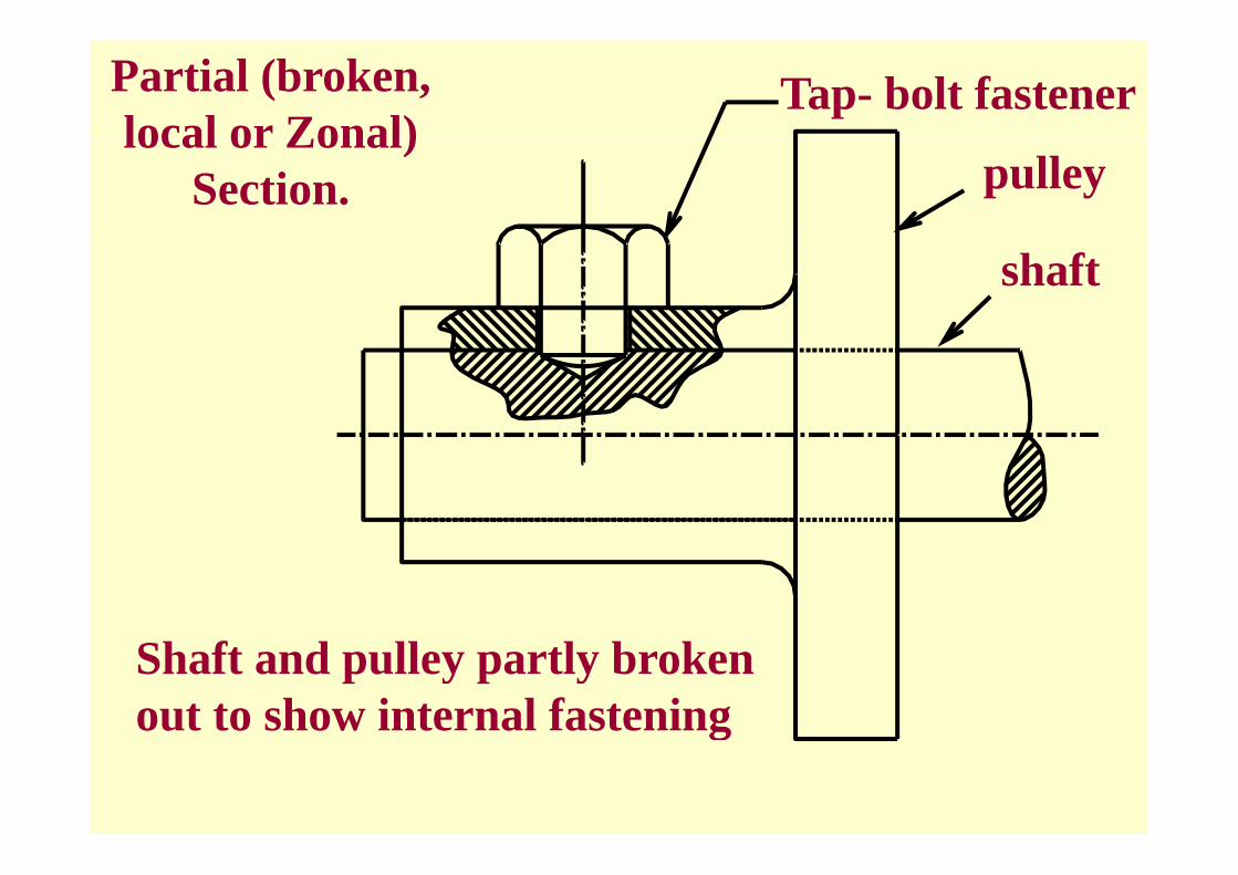
Tap- bolt fastenerPartial (broken, local or Zonal)
pulleylocal or Zonal)
Section.
shaft
Shaft and pulley partly broken out to show internal fasteningg
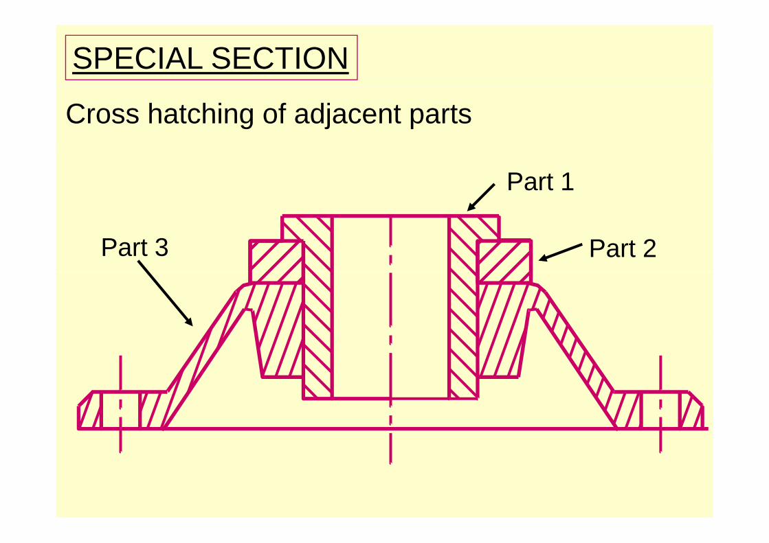
SPECIAL SECTION
Cross hatching of adjacent parts
Part 1
Part 2Part 3
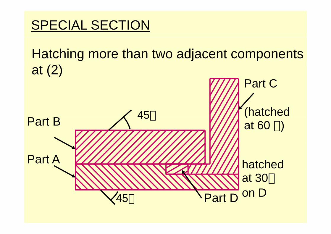
SPECIAL SECTION
Hatching more than two adjacent components at (2)
Part C
P B(hatched45Part B(at 60 )
45
Part A hatched
Part D45
at 30on DPart D45 o

A B
F.V.
SEC.T.V.Two vertical plates ,fastened by a horizontalrivet is shown in its F.V. & T.V., cut by horizontalsection plane. Note: the rivet is shown in section inT.V.
AimAim::--SketchSketch--11,, showsshows IsometricIsometric ViewView ofof aamachinemachine partpart.. DrawDraw itsits followingfollowingorthographicorthographic viewsviews usingusing thirdthird angleangle
SOLUTION`SOLUTION`
g pg p gg ggmethodmethod ofof projections,projections, givinggiving dimensionsdimensions..(1) Sectional F.V.(1) Sectional F.V.--AAAA(2) T V(2) T V(2) T.V.(2) T.V.(3) L.H.S.V(3) L.H.S.V
AA TOP VIEWTOP VIEWR35R35
AAAA3030
AA
88
AATOP VIEWTOP VIEW
Ö20Ö20
Φ20Φ20Φ36Φ36
ÖÖ
Ö36Ö36
002 HOLES,Ö 142 HOLES,Ö 14
6565
4`4`
100
100
AA
1414
AA AALEFT HAND SIDE VIEWLEFT HAND SIDE VIEW SECTIONAL FRONT VIEW AASECTIONAL FRONT VIEW AA
XX
SCALE:SCALE:-- 1:11:1SYMBOL OF PROJECTION METHOD, NOT SHOWNSYMBOL OF PROJECTION METHOD, NOT SHOWN
SketchSketch--11

SOLUTION`SOLUTION`Aim:Aim:--SketchSketch--1, shows Isometric View of a 1, shows Isometric View of a machine part. Draw its following machine part. Draw its following
th hi i i thi d lth hi i i thi d lorthographic views using third angle orthographic views using third angle method of projections, giving dimensions.method of projections, giving dimensions.(1) Sectional F.V.(1) Sectional F.V.--AAAA(2) T.V.(2) T.V.
SCALE:SCALE:-- 1:11:1
AAAA
R35R35
( )( )(3) L.H.S.V(3) L.H.S.V
3030
AATOP VIEWTOP VIEW
SCALE:SCALE: 1:11:1
88Φ20Φ20
R35R35AA
1414
88
Φ20Φ20Φ36Φ36Φ36Φ36
100
1002 HOLES,Ö 142 HOLES,Ö 14
AALEFT HAND SIDE VIEWLEFT HAND SIDE VIEW SECTIONAL FRONT VIEW AASECTIONAL FRONT VIEW AA
SYMBOL OF PROJECTION METHOD, NOT SHOWNSYMBOL OF PROJECTION METHOD, NOT SHOWN
XXAA

AA
AAAA
XX

B
XX
A
BB
A

AimAim::--SketchSketch--11,, showsshows IsometricIsometric ViewView ofof aamachinemachine partpart.. DrawDraw itsits followingfollowingorthographicorthographic viewsviews usingusing thirdthird angleangle
SOLUTION`SOLUTION`
g pg p gg ggmethodmethod ofof projections,projections, givinggiving dimensionsdimensions..(1) Sectional F.V.(1) Sectional F.V.--AAAA(2) T V(2) T V(2) T.V.(2) T.V.(3) L.H.S.V(3) L.H.S.V
AA TOP VIEWTOP VIEWR35R35
AAAA3030
AA
88
AATOP VIEWTOP VIEW
Ö20Ö20
Φ20Φ20Φ36Φ36
ÖÖ
Ö36Ö36
002 HOLES,Ö 142 HOLES,Ö 14
6565
4`4`
100
100
AA
1414
AA AALEFT HAND SIDE VIEWLEFT HAND SIDE VIEW SECTIONAL FRONT VIEW AASECTIONAL FRONT VIEW AA
XX
SCALE:SCALE:-- 1:11:1SYMBOL OF PROJECTION METHOD, NOT SHOWNSYMBOL OF PROJECTION METHOD, NOT SHOWN
SketchSketch--11