Embed Size (px)
Citation preview

Sectional metering devices
Product series VPFor oil and greaseFor use in SKF CircOil circulating and SKF ProFlex progressive centralized lubrication systems
Fields of application• Metal-forming machinery
• Vehicles
• Construction machinery
• Production systems in the automotive
industry
• Packaging and printing machines
Advantages• For universal use in continuous or inter-
mittent operations
• Versatile – features metering sections
with variable dosing amounts and internal
and external consolidation of outlets
• Expandable by attaching flow limiters and
directional solenoid valves
• Can be monitored using piston detectors
or visual cycle indicators
• High function reliability due to standard
equipped check valves
• Simple to service – separator plates fea-
ture vulcanized seals that cannot be
detached
• Powerful – max. 20 outlets for volumetric
flow of up to 1 000 cm³/min
• Easy to install alternative outlets on top
and side

PU
B L
S/P
2 1
5400 E
N ·
1-3
016-E
N
CAD models for the products shown in this brochure can be
downloaded at: skf-lubrication.partcommunity.com
!Important information on product usageSKF and Lincoln lubrication systems or their components are not
approved for use with gases, liquefied gases, pressurized gases in solution and fluids with a vapor pressure exceeding normal atmospheric pressure (1 013 mbar) by more than 0,5 bar at their maximum permissible temperature.
2

PU
B L
S/P
2 1
5400 E
N ·
1-3
016-E
N
Table of contents
Product overview . . . . . . . . . . . . . . . . . . . . . . . . . . . . . . . . . . . . . . . . . . . . . . . . . . . . . . . 4
General . . . . . . . . . . . . . . . . . . . . . . . . . . . . . . . . . . . . . . . . . . . . . . . . . . . . . . . . . . . . . . . .5
Operation of sectional metering devices . . . . . . . . . . . . . . . . . . . . . . . . . . . . . . . . . . . . . 5
Information on the design . . . . . . . . . . . . . . . . . . . . . . . . . . . . . . . . . . . . . . . . . . . . . . . . 5
Quantity distribution . . . . . . . . . . . . . . . . . . . . . . . . . . . . . . . . . . . . . . . . . . . . . . . . . . . . 6
Operating pressure and temperature . . . . . . . . . . . . . . . . . . . . . . . . . . . . . . . . . . . . . . . 6
Tightening torques . . . . . . . . . . . . . . . . . . . . . . . . . . . . . . . . . . . . . . . . . . . . . . . . . . . . . . 6
Monitoring . . . . . . . . . . . . . . . . . . . . . . . . . . . . . . . . . . . . . . . . . . . . . . . . . . . . . . . . . . . . 6
Attachments . . . . . . . . . . . . . . . . . . . . . . . . . . . . . . . . . . . . . . . . . . . . . . . . . . . . . . . . . . . 6
Consolidation of outlets . . . . . . . . . . . . . . . . . . . . . . . . . . . . . . . . . . . . . . . . . . . . . . . . . . 6
Sectional metering device VP in basic design . . . . . . . . . . . . . . . . . . . . . . . . . . . . . . . . . 7
Sectional metering device VP with piston detector and cycle indicator . . . . . . . . . . . . . 8
Sectional metering device VP with flow limiter . . . . . . . . . . . . . . . . . . . . . . . . . . . . . . . 9
Sectional metering device VP with directional solenoid valve . . . . . . . . . . . . . . . . 10–11
Order code on Cadenas . . . . . . . . . . . . . . . . . . . . . . . . . . . . . . . . . . . . . . . . . . . . . . 12–13
Order example . . . . . . . . . . . . . . . . . . . . . . . . . . . . . . . . . . . . . . . . . . . . . . . . . . . . . . . . 14
Accessories . . . . . . . . . . . . . . . . . . . . . . . . . . . . . . . . . . . . . . . . . . . . . . . . . . . . . . . . . . . 15
Exploded view . . . . . . . . . . . . . . . . . . . . . . . . . . . . . . . . . . . . . . . . . . . . . . . . . . . . . . . . 16
Spare parts . . . . . . . . . . . . . . . . . . . . . . . . . . . . . . . . . . . . . . . . . . . . . . . . . . . . . . . 16–19
3
PU
B L
S/P
2 1
5400 E
N ·
1-3
016-E
N
Sectional metering device, product series VP
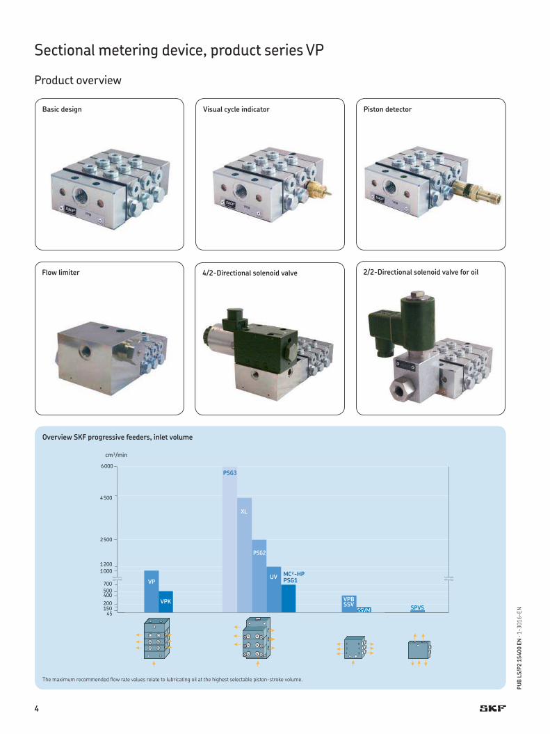
Product overview
Basic design Piston detectorVisual cycle indicator
Flow limiter 4/2-Directional solenoid valve 2/2-Directional solenoid valve for oil
150200
400
45
500
6000
2500
1000
cm³/min
4500
1200
700 VP
VPK
MC²-HPPSG1
UV
PSG2
XL
PSG3
SSVM
VPBSSV
SPVS
Overview SKF progressive feeders, inlet volume
The maximum recommended flow rate values relate to lubricating oil at the highest selectable piston-stroke volume.
4

PU
B L
S/P
2 1
5400 E
N ·
1-3
016-E
N
Sectional metering device, product series VP
Product description
General
The sectional metering device VP, which be-
longs to the progressive feeder range, is
available in the designs VPM (metric-threaded
connectors) and VPG (inch-threaded con-
nectors). With their metering sections, VPM
and VPG cover a metering volume per outlet
and cycle of 0.1 cm3 (T- section) to 1.2 cm3
(S-section). The inlet of the feeder is located
at an inlet section and the outlets are at the
downstream feeder sections. The delivery
ducts are sealed by elastic seals. An end
section is located downstream of the last
feeder section. All sections are interconnect-
ed with tie-rods. They seal the feeder
assembly.
The volumetric flow, which is sent via a
tube, is forcibly distributed in a predeter-
mined ratio to the outlets, i.e. to the lubrica-
tion points or the downstream progressive
feeders. Pistons, which are aligned in series,
meter the lubricant for two opposite outlets
each and control the function of the neigh-
boring piston. This way, the function of the
sectional metering device can be checked by
monitoring any piston with a cycle indicator
or a piston detector.
The standard add-on check valves offer
high functional reliability (for high or differ-
ent back pressures). They also provide an
accurate feed and safe blocking behavior,
even for internal combinations.
Operation († Fig. 1)
The task of the progressive feeder is to dis-
tribute consecutively specified portions of
the pressure-fed lubricant (grease or oil) to
the connected lubrication points.
The discharge of the lubricant continues
as long as it is pressure-fed to the progres-
sive feeder. The specified portions are gen-
erated through the piston movement. Two
lubricant outlets on the two end positions of
the piston travel are allocated to each piston.
The number of pistons within a feeder is
from 3–10 variable. If lubricant is pressure-
fed, the pistons of a feeder move in turn to
their end position. The piston movement
displaces a portion of the lubricant that is
downstream of the piston to the down-
stream outlet. The movement of a piston
can only start after the upstream piston has
been moved to its end position. If all pistons
are in their left or right end position, internal
connecting bores in the feeder ensure a de-
fined and continued running of the pistons.
When all pistons have been moved once
to the left as well as to the right end posi-
tion, all connected lubricant points have
been supplied once with the preset lubricant
quantity.
The portions for both outlets are deter-
mined by the diameter and the travel of the
piston. The selection of the required portion
is made during the design of the feeder.
A subsequent change of the portions is only
possible through a modification of the
feeder.
Information on the design
The general criteria for the design of pro-
gressive feeders also apply without restric-
tions to the sectional metering device VP. The
most important criterion is the number of
cycles (stroke rate). They should be held as
low as possible by selecting high-volume
feeders. Maximum value of 200 cycles/min
should not be exceeded
Thus, pressure losses and noise level will
also be reduced. In case of an installation on
movable machine parts or in case of strong
vibrations (e.g. on presses), the piston posi-
tion of the feeder should not be the same as
the direction of movement of the machine
part.
For the VP feeder, the minimum number
of feeder sections is 3 and the maximum
number is 10.
6a 5a
6
3a 2a
1a
5
4
4a
3 2
1
6
Fig. 1
Section view
left
/rea
r
Piston side 4 is pressurized by the pump, piston side 1 has delivered lubricant to outlet 1a. The connection between the main line and piston side 5 has become free due to the stroke of piston 1/4.
Piston side 5 is pressurized and piston side 2 delivers the lubricant via outlet 2a. Piston side 6 is the next to be pressurized, etc.
6a 5a
6
3a 2a
1a
4
4a
3
1
5
2
6
righ
t/re
ar
left
/fro
nt
righ
t/fr
ont
left
/rea
rri
ght/
rear
left
/fro
nt
righ
t/fr
ont
Lubri-cantinlet
5

PU
B L
S/P
2 1
5400 E
N ·
1-3
016-E
N
Quantity distribution († Fig. 2)
Sectional metering devices distribute an
amount delivered by a pump to several out-
lets while the feeder determines the volu-
metric ratio.
The different output quantities within a
feeder are achieved by the use of various
piston diameters or the joining of two or
more outlets. The indicated lubricant quanti-
ties result from the piston diameter and the
maximum travel of the piston. Depending on
the system design, these capacities may
vary by 40 percent.
For the sectional metering devices VPM
and VPG, sections for two connections (T =
twin) or for one connection (S = single) are
available. In case of single sections, the two
opposite outlets are connected internally,
whereby one outlet is closed.
Each section is equipped with a lateral
and an upper outlet per side. Only one outlet
can be connected, the second one has to be
blocked by either a plug or an overpressure-
indicator. On demand, the crossporting also
can be connected to the upper outlets.
Tightening torques
During the installation of the VP feeder, con-
sisting of inlet section, inlet plate, twin and
single sections, separator plates as well as
end plate and end section, the following
tightening torques have to be adhered to for
the tie-rods and nuts:
Tightening torque
Tie-rod (2x) each 2,4 Nm
Nut for tie-rod M8 (2x) each 12,0 Nm
Monitoring
All standard sections can be monitored di-
rectly by means of a piston detector. Fur-
thermore, the piston movement can be
monitored by visual stroke monitoring.
Both monitoring models can be used for
oil as well as for grease.
Attachments
The modular structure of the sectional me-
tering device becomes apparent when you
consider the range of attachments. Option-
ally, the sectional metering device VP can be
equipped with:
• upstream flow limiter for oil
• upstream directional solenoid valve for oil
and grease
Consolidation of outlets († Fig. 3)
A later combination of two outlets for sec-
tional metering devices is only possible with
a crossporting bar that is screwed into the
upper alternative outlets. Any odd number
of outlets can be achieved with the help of
S-sections without additional crossporting
bars.
The crossporting bar is used to combine
the lubricant outputs of two adjacent feeder
sections via the alternative outlets on top of
the feeder.
Sectional metering device, product series VP
Monitoring and attachments
T (Twin) = two outlet ports
Example: 2S = 0.4 cm³ per cycle from one outlet (F) 1)
3S = 0.6 cm³ per cycle from one outlet (H) 1)
6S = 1.2 cm³ per cycle from one outlet (Q) 1)
Example: 2T = 0.2 cm³ per outlet (E) 1)
3T = 0.3 cm³ per outlet (G) 1)
6T = 0.6 cm³ per outlet (N) 1)
Example: 2S = 0.8 cm³ per cycle from one outlet 2S
S (Single) = one outlet port
C (Crossporting)
Combining four piston displacements of two sections to form one outlet port.
Bore
Fig. 2
Consolidations of capacities
TTT
Tx
x SSx x
xx
TS x
ST
xx
ST
x
TT
xxTT
x
x SS
Second outlet port must not be closed on
T-sections.
S-section can supply only one outlet port
exactly!
This outlet port has to be closed since crossporting is involved!
Plug and outlet side can be interchanged with each other.
When two T-sections are con-nected by crossporting, one outlet must be open on the
crossporting side!
One external crossporting bar
(2S-section)
Two external crossporting bars(1T, 1S-section)
If you want to combine 2 sections (4 outlets) to form one outlet port, you can do it
this way .................................... but it's better this way!
Fig. 3
Consolidation of outlets
1) † Order code choice 8
Screw plug
6

PU
B L
S/P
2 1
5400 E
N ·
1-3
016-E
N
max. 5
1
10
28
.5 35
3.5
ø20
72
(82.5)
7
22
L2
L1±27
24
24
±0.2
ø7 (2x)
10.5
6.5
41
13
5
VP sectional metering device, basic design
Sectional metering device, product series VP
Basic design for oil and grease
Dimensions
Inlet: VPM = M14×1.5 VPG = G1/4
Outlet: VPM = M10×1 VPG = G1/8
Number of Number offeeder possible L1 L2 Weight
Typ sections outlets [mm] [mm] [kg]
VPM-3 / VPG-3 3 6 84 98 1.73
VPM-4 / VPG-4 4 8 104 118 2.1
VPM-5 / VPG-5 5 10 124 138 2.47
VPM-6 / VPG-6 6 12 144 158 2.84
VPM-7 / VPG-7 7 14 164 178 3.21
VPM-8 / VPG-8 8 16 184 198 3.58
VPM-9 / VPG-9 9 18 204 218 3.95
VPM-10 / VPG-10 10 20 224 238 4.32
Technical data
Type . . . . . . . . . . . . . . . . . . Hydraulically controlledMounting position . . . . . . . . . . . . Any1)
Ambient temperature range . . . . . . . –25 to +90 °CFeeder section. . . . . . . . . . . . . . See tableOccupied outlets. . . . . . . . . . . . . 1 to 20
MaterialInlet, separator and end section . . . . . Steel, galvanized, NBRSections . . . . . . . . . . . . . . . . Steel, galvanized
Hydraulic systemOperating pressure, max. . . . . . . . . Oil 200 bar, grease 300 barVolume per outlet and cycle . . . . . . . See tableLubricant . . . . . . . . . . . . . . . . Mineral oils, greases based
on mineral oil,environmentally friendly andsynthetic oils and greases
Operating viscosity . . . . . . . . . . . > 12 mm2/sWorked penetration . . . . . . . . . . . ≥ 265 x 0,1 mm
(up to NLGI Grade 2)
Selection of feeder sections
Quantity per cycle Number of Description Identification and outlet [cm³] outlets of the sections letter/Order code
0.10 2 1T C0.20 2 2T E0.30 2 3T G0.40 2 4T J0.50 2 5T L0.60 2 6T N0.20 1 1S D0.40 1 2S F0.60 1 3S H0.80 1 4S K1.00 1 5S M1.20 1 6S Q
End section
Inlet section
Feeder section
1) In case of installation on moving machine parts or in case of strong vibrations (e.g., on pressing machines), the piston position of the feeder must not match the direction of move-ment of the machine part; instead, it must be at a 90° angle to the force of the machine.
Lubricant inlet
Lubricant outlet
7

PU
B L
S/P
2 1
5400 E
N ·
1-3
016-E
N
Sectional metering device, product series VP
Monitoring with piston detector and cycle indicator, for oil and grease
With piston detector
M12×1
53
.5
3T2T 4T
Sectional metering device VP with piston detector
For other dimensions, see VP basic design † page 6
With cycle indicator
16
VPM
2T
VPM VPM
3T 4T
26
Sectional metering device VP with visual cycle indicator
For other dimensions, see VP basic design † page 7
!Note!
Electrical plug and socket connections are ordered sepa-
rately † page 15.
Technical data
Basis design † Technical data page 7
Piston detector, electrical 1)
Internal thread . . . . . . . . . . . . . M12×1Ambient temperature range . . . . . . . –25 to +80 °COperating pressure max. . . . . . . . . 300 barWeight . . . . . . . . . . . . . . . . . 0.046 kgDesign . . . . . . . . . . . . . . . . . 4-point LEDRated voltage . . . . . . . . . . . . . . 10 to 36 V DCResidual ripple (2-pin) . . . . . . . . . 3 to 15%Residual ripple (3-pin) . . . . . . . . . 10%Max. load current . . . . . . . . . . . . 100 mAProtection class . . . . . . . . . . . . . IP67Min. load current (2-pin). . . . . . . . . 4 mAOutlet function (3-pin) . . . . . . . . . . PNP contact
Cycle indicator, visualAmbient temperature range . . . . . . . –15 to +75 °COperating pressure max. . . . . . . . . 300 barWeight . . . . . . . . . . . . . . . . . 0.02 kg
1) The piston detector is designed for a service life of approx. 10-15 million cycles.This value may be significantly exceeded depending on the application, external environmental influences, medium, pressure, and cycle speed. Please contact the manufacturer if in doubt.
8

PU
B L
S/P
2 1
5400 E
N ·
1-3
016-E
N
Sectional metering device, product series VP
with flow limiter SP/SMB8, for oil
M14×1.5 (G1/4)56
58
44
35
ø7
ø11
64
78
8
72
36
14
24 3T
VPMVPM
2T
VPM
4T
30
27
Sectional metering device VP with flow limiter
For other dimensions, see VP basic design † page 7
Technical data
Basis design † Technical data page 7
Flow limiter SP/SMB8Type . . . . . . . . . . . . . . . . . . 2-way flow limiter valveAmbient temperature range . . . . . . . 0 to +100 °COperating pressure max. . . . . . . . . 200 barInlet volume . . . . . . . . . . . . . . 0.1 to 1.0 l/minLubricant . . . . . . . . . . . . . . . . Mineral oils, environmentally
friendly and synthetic oilsOperating viscosity . . . . . . . . . . . 20 to 600 mm²/s
Weight . . . . . . . . . . . . . . . . . 1.95 kgMaterial . . . . . . . . . . . . . . . . Steel, galvanized
Plug-in nozzles for flow limiter
Nominal volumetric flow up to 1.09 l/min 1)
Nominal volume[l/min]
Nozzle-ø[mm]
Code
0.08 0.5 A0.12 0.55 B0.15 0.6 C0.21 0.65 D0.25 0.7 E0.29 0.75 F0.35 0.8 G0.41 0.85 H0.47 0.9 J0.56 0.95 K0.65 1 L0.73 1.05 M0.79 1.1 N0.88 1.15 P0.98 1.2 Q1.09 1.25 R
1) The values in the table are based on a differential pressure of 20 bar and viscosity of 300 mm2/s. Other differential pressures or viscosities result in slightly different delivery rates. These can be determined precisely using the charts for delivery rates and correction factors for the pressure († brochure 1-3028-EN).
9

PU
B L
S/P
2 1
5400 E
N ·
1-3
016-E
N
Sectional metering device, product series VP
with directional solenoid valve, for oil
With 4/2-directional solenoid valve Technical data
Basis design † Technical data page 7
4/2-directional solenoid valveAmbient temperature range . . . . . . . –15 to +75 °COperating pressure max. . . . . . . . . 150 barLubricant . . . . . . . . . . . . . . . . Mineral oils, environmentally
friendly and synthetic oilsWeight . . . . . . . . . . . . . . . . . 2.91 kgElectrical design . . . . . . . . . . . . Pusher/solenoidElectrical connection . . . . . . . . . . DIN EN175301-803System voltage . . . . . . . . . . . . . 24 V DCDesign . . . . . . . . . . . . . . . . . Continuity to feeder
normally closed (NC) or open (NO)
2/2-directional solenoid valveAmbient temperature range . . . . . . . . . . –15 to +75 °COperating pressure max. . . . . . . . . . . . . 150 barLubricant . . . . . . . . . . . . . . . . Mineral oils, environmentally
friendly and synthetic oilsWeight . . . . . . . . . . . . . . . . . 0,61 kgElectrical connection . . . . . . . . . . DIN EN175301-803System voltage . . . . . . . . . . . . . 24 V DCDesign . . . . . . . . . . . . . . . . . Continuity to feeder
normally closed (NC)
P
B
A
T
68
148
BP
VPM VPM VPM
2T 3T 4T
P
T
A
B
P
T
A
B
Sectional metering device VP with 4/2-directional solenoid valve
For other dimensions, see VP basic design † page 7
With 2/2-directional solenoid valve
Sectional metering device VPG with 2/2-directional solenoid valve
For other dimensions, see VP basic design † page 7
Continuity to feeder normally closed (NC)
Continuity to feeder normally closed (NC) P–B
Continuity to feeder normally open (NO) P–A
10

PU
B L
S/P
2 1
5400 E
N ·
1-3
016-E
N
Sectional metering device, product series VP
with directional solenoid valve, for grease
A
Sectional metering device VP with 2/2-directional solenoid valve
with 2/2-directional solenoid valve Technical data
Basis design † Technical data page 7
Ambient temperature range . . . . . . . –25 to +80 °COperating pressure max. . . . . . . . . 300 barLubricant . . . . . . . . . . . . . . . . Greases up to NLGI Grade 2
Weight with housing . . . . . . . . . . 1.5 kgElectrical design . . . . . . . . . . . . Poppet valveElectrical connection . . . . . . . . . . DIN EN175301-803System voltage . . . . . . . . . . . . . 24 V DCDesign . . . . . . . . . . . . . . . . . Continuity to feeder
normally closed (NC)
11

PU
B L
S/P
2 1
5400 E
N ·
1-3
016-E
N
Order Code
Sectional metering device of product series VP*)
1 Thread type
Inlet thread M14×1.5, outlet thread M10×1 M
Inlet thread G1/4, outlet thread G1/8 G
2 Selection of monitoring
none X
Piston detector 2-pin, M12×1 plug 2
Piston detector 3-pin, M12×1 plug (wire breakage protection) 3
Cycle indicator, visual (plunger rod) 1) Y
1) The installation of the cycle indicator is only possible from feeder section 2T and 2S, respectively!
3 Selection of installation position for monitor
X none
left-hand side right-hand side
U 10 V
S 9 T
Q 8 R
N 7 P
L 6 M
J 5 K
G 4 H
E 3 F
C 2 D
A 1 B
Inlet
4 Selection of attachments
VP
G
VP
M
none X X
Flow limiter with nominal volume up to 1.09 l/min† Plug-in nozzles table 5
A A
4/2-directional solenoid valve for oil, continuityto feeder normally open (NO) P–A
B B
4/2-directional solenoid valve for oil, continuityto feeder normally closed (NC) P–A
C C
2/2-directional solenoid valve for oil, continuityto feeder normally closed (NC)
E –
2/2-directional solenoid valve for grease, continuityto feeder normally closed (NC)
F F
5 Plug-in nozzles for flow limiter 2)
Nominal Nominalvolume Nozzle-ø volume Nozzle-ø[l/min] [mm] [l/min] [mm]
none X 0.47 0.9 J
0.08 0.5 A 0.56 0.95 K
0.12 0.55 B 0.65 1 L
0.15 0.6 C 0.73 1.05 M
0.21 0.65 D 0.79 1.1 N
0.25 0.7 E 0.88 1.15 P
0.29 0.75 F 0.98 1.2 Q
0.35 0.8 G 1.09 1.25 R
0.41 0.85 H
2) The values in the table are based on a differential pressure of 20 bar and viscosity of 300 mm2/s.Other differential pressures or viscosities result in slightly different delivery rates. These can be determined precisely using the charts for delivery rates and correction factors for the pressure († brochure 1-3028-EN).
Feeder information Choice 8 /9 /10: information on sections 1 to 10 as seen from inlet
Order example: VPG3DXXEX-LDD-GDD-QHS-QSE († page 14)
Order code VP 1 2 3 4 5 6 7 – _ _ _–_ _ _–_ _ _–_ _ _–_ _ _–_ _ _–_ _ _–_ _ _–_ _ _-_ _ _
*) Online configurable under skf-lubrication.partcommunity.com († page 14).
12

PU
B L
S/P
2 1
5400 E
N ·
1-3
016-E
N
6Selection of inlet screw union V
PG
VP
M
none X X
Straight connector for tube ø 6 mm 1), L – A
Straight connector for tube ø 6 mm 1), S B –
Straight connector for tube ø 8 mm 1), L C –
Straight connector for tube ø 8 mm 1), S – D
Straight connector for tube ø 10 mm 1), L E E
Straight connector for tube ø 12 mm 1), L F F
Straight connector, EO2 for tube ø 6 mm G G
Straight connector, EO2 for tube ø 8 mm H H
Straight connector, EO2 for tube ø 10 mm J J
Straight connector, EO2 for tube ø 12 mm K –
Quick connector for tube ø 6 mm L –
Elbow for tube ø 8 mm, tapered 1), L M –
Elbow for tube ø 10 mm, tapered 1), L N N
Banjo fitting for tube ø 6 mm 1), S P –
Banjo fitting for tube ø 8 mm 1), L Q –
Banjo fitting for tube ø10 mm 1), L R R
1) Solderless pipe unions with cutting sleeve acc. to DIN 2353
7 Options
none X
Blockage indicator on all open outlets (opening pressure)
Open at 50 bar R
Open at 100 bar S
Open at 150 bar T
Open at 200 bar U
910
2nd place outlet screw union, left-hand side; 3rd place outlet screw union, right-hand side V
PG
VP
M
No outlet port, screw plug S S
Outlet port without screw unions X X
Outlet port with 4 mm outlet screw union 4), tapered, LL – A
Outlet port with 4 mm outlet screw union 4), LL B –
Outlet port with 6 mm outlet screw union 4), tapered, LL – C
Outlet port with 6 mm outlet screw union 4), L D D
Outlet port with 8 mm outlet screw union 4), tapered, LL E E
Outlet port with 10 mm outlet screw union 4), tapered, L F –
Outlet port with 4 mm outlet screw union, EO2 4) G G
Outlet port with 6 mm outlet screw union, EO2 4) J J
ø4 mm quick connector K K
ø4 mm quick connector, tapered – L
ø6 mm quick connector M M
ø6 mm quick connector, tapered N N
Outlet port with 4 mm outlet screw union, with CV P P
Outlet port with 6 mm outlet screw union, with CV Q Q
Outlet port with 8 mm outlet screw union, with CV T T
Outlet port with 10 mm outlet screw union, with CV – U
Outlet port with 4 mm banjo fitting 4), LL W –
Outlet port with 6 mm banjo fitting 4), L Z Z
Outlet port with 6 mm banjo fitting 4), LL – 1
4 mm quick connector-banjo fitting 2 2
4 mm quick connector-banjo fitting, tapered – 3
6 mm quick connector-banjo fitting 4 4
6 mm quick connector-banjo fitting, tapered – 5
Crossporting forwards (seen from the inlet) V V
Crossporting backwards (seen from the inlet) H H
4) Solderless pipe unions with cutting sleeve acc. to DIN 2353
LL-series = extra light version, L-series = light version, S-series = heavy duty versionCV = Check valve
Selection of outlet ports (indicate selections 9 and 10!)
left-hand † † right-hand
10
9
8
7
6
5
4
3
2
1
Inlet
9 10
8 Selection of feeder sections
1st place section size 2) (seen from the inlet)
Number of outlets 2 (Twin) Number of outlets 1 (Single)
Volume per cycle and outlet[mm³] 3)
Designationof sections
Volume per cycle and outlet[mm³] 3)
Designationof sections
100 1T C 200 1S D
200 2T E 400 2S F
300 3T G 600 3S H
400 4T J 800 4S K
500 5T L 1000 5S M
600 6T N 1200 6S Q
2) Smallest possible feeder size = 3 effective sections3) Data in cm³ † page 6
13

PU
B L
S/P
2 1
5400 E
N ·
1-3
016-E
N
Order example
Sectional metering device of product series VP
Order code: VPG3DXXEX-LDD-GDD-QHS-QSE
We recommend that you enter your desired
sectional metering devices in Cadenas at
skf-lubrication.partcommunity.com so
that you can configure it quickly.
You will receive:
• A 3D drawing
• A 2D drawing
• A dimensioned drawing
• A complete order code
• A legend
6SQ
6SQ
3TG
5TL
10
GE
8 GE
6 GE
6 GE
S
D
D
E
GE 6
GE 6D
D
S
H
Order example diagramDesignation
Description Clarification
Progressive sectional metering device VP
Thread type G (inlet thread G1/4, outlet thread G1/8)
Feeder size 4 sections
Monitoring type 3 (P3 piston detector 3-pin, M12×1 plug)
Mounting position of the monitoring system D (right-side, on 2nd section)
Attachments X (without)
Plug-in nozzles for flow limiterattachment
X (without)
Inlet screw union E (Straight connector for tube ø 10 mm, L)
Option X (without blockage indicator)
1. SectionFeeder section L (5T – 0,50 cm³, 2 outlets)
left side of section D (Straight connector for tube ø 6 mm, L)
right side of section D (Straight connector for tube ø 6 mm, L)
2. Section
Feeder section G (3T – 0.30 cm³, 2 outlets)
left side of section D (Straight connector for tube ø 6 mm, L)
right side of section D (Straight connector for tube ø 6 mm, L)
3. Section
Feeder section Q (6S – 1.20 cm³, 1 outlet)
left side of section H (Crossporting backwards)
right side of section S (no outlet port, screw plug)
4. Section
Feeder section Q (6S – 1.20 cm³, 1 outlet)
left side of section S (no outlet port, screw plug)
right side of section E (Straight connector for tube ø 8 mm, tapered, LL)
1
2
3
4
5
6
7
8
9
10
8
9
10
8
9
10
8
9
10
14

PU
B L
S/P
2 1
5400 E
N ·
1-3
016-E
N
Accessories
179-990-033Square connector179-990-033
Electrical plug-in connections
Square connectorOrder No. Designation
179-990-033 Square connector per DIN EN 175301-803A, cable diameter 6–10 mm, 3-pin +PE, max. 1.5 mm²
Circular connector M12x1
179-990-371 Straight circular connector (A), cable diameter –6 mm, 4-pin, max. 0.75 mm²
179-990-600 Straight circular connector (B), 4-pin with integrally extruded cable, 5 m, 4×0,25 mm²
179-990-372 Angled circular connector (C), cable diameter 4–6 mm, 4-pin, max. 0.75 mm²
179-990-601 Angled circular connector (D), with integrally extruded cable, 5 m, 4×0,25 mm²
A B C D
Circular connector M12×1
† Brochure 1-1730-EN
15

PU
B L
S/P
2 1
5400 E
N ·
1-3
016-E
N
Exploded view
Associated spare parts tables † pages 17–19.
17
18
16
15
26
1
23
22
21
24 25
1920
28
27
6
9
7
29
43
2
12
5
11
13
14
Spare parts table 1
Inlet screw unionVPG VPM
Item Description Order No. Order No.
1 Straight connector for tube ø 6 mm 1), L – 406-413
Straight connector for tube ø 6 mm 1), S 406-413W –
Straight connector for tube ø 8 mm 1), L 408-403W –
Straight connector for tube ø 8 mm 1), S – 408-413
Straight connector for tube ø 10 mm 1), L 410-403W 410-403
Straight connector for tube ø 12 mm 1), L 412-423W 412-423
Straight connector, EO2 for tube ø 6 mm 471-006-161 471-006-351
Straight connector, EO2 for tube ø 8 mm 471-008-161 471-008-351
Straight connector, EO2 for tube ø 10 mm 471-010-161 471-010-351
Straight connector, EO2 for tube ø 12 mm 471-012-161 –
Quick connector for tube ø 6 mm 406-054-VS –
Elbow for tube ø 8 mm, tapered 1), L 408-405W –
Elbow for tube ø 10 mm, tapered 1), L 410-405W 410-405
Banjo fitting for tube ø 6 mm 1), S 445-516-061 –
Banjo fitting for tube ø 8 mm 1), L 445-516-081 –
Banjo fitting for tube ø 10 mm 1), L 445-516-101 445-535-101
8
10
17
1) Solderless pipe unions with cutting sleeve acc. to DIN 2353
LL-series = extra-light version, L-series = light version, S-series = heavy-duty version
Spare parts
16

PU
B L
S/P
2 1
5400 E
N ·
1-3
016-E
N
Spare parts
Spare parts table 4
MonitoringVPG VPM
Item Description Order No. Order No.
3 Piston detector, 2-pin 177-300-091 177-300-091
Piston detector, 3-pin 177-300-094 177-300-094
4 Associated washer WVN501-12×1.5 WVN501-12×1.5
Spare parts table 2
Outlet screw unionVPG VPM
Item Description Order No. Order No.
2 Straight connector for tube ø 4 mm 1), tapered, LL – 404-403
Straight connector for tube ø 4 mm 1), LL 404-403W –
Straight connector for tube ø 6 mm 1), tapered, LL – 406-423
Straight connector for tube ø 6 mm 1), L 406-403W 406-403
Straight connector for tube ø 8 mm 1), tapered, LL 408-423W 441-008-511
Straight connector for tube ø 10 mm 1), tapered, L 410-443W –
Straight connector for tube ø 4 mm, EO2 1) 471-004-191 471-004-311
Straight connector for tube ø 6 mm, EO2 1) 471-006-192 471-006-311
Quick connector for tube ø 4 mm 404-040-VS 404-006-VS
Quick connector for tube ø 4 mm, tapered – 451-004-518-VS
Quick connector for tube ø 6 mm 456-004-VS 406-004-VS
Quick connector for tube ø 6 mm, tapered 406-423W-VS 451-006-518-VS
ø 4 mm outlet screw union, with CV VPG-RV VPM-RV4
ø 6 mm outlet screw union, with CV VPG-RV6 VPM-RV
ø 8 mm outlet screw union, with CV VPG-RV8 VPM-RV8
ø 10 mm outlet screw union, with CV – VPM-RV10
ø 4 mm banjo fitting 3), LL 445-519-041 –
ø 6 mm banjo fitting 3), L 445-519-061 445-531-061
ø 6 mm banjo fitting 3), LL – 445-531-062
ø 4 mm quick connector-banjo fitting 504-108-VS 504-102-VS
ø 4 mm quick connector-banjo fitting, tapered – 455-531-048-VS
ø 6 mm quick connector-banjo fitting 506-108-VS 506-140-VS
ø 6 mm quick connector-banjo fitting, tapered – 455-531-068-VS
1) Solderless pipe unions with cutting sleeve acc. to DIN 2353
LL-series = extra-light version, L-series = light version, S-series = heavy-duty version, CV = check valve
17

PU
B L
S/P
2 1
5400 E
N ·
1-3
016-E
N
Spare parts
Spare parts table 4
FeederVPG VPM
Item Description Order No. Order No.
5 Feeder section 2T with cycle indicator right VPG-K-2T-ZY-R VPM-K-2T-ZY-R
Feeder section 3T with cycle indicator right VPG-K-3T-ZY-R VPM-K-3T-ZY-R
Feeder section 4T with cycle indicator right VPG-K-4T-ZY-R VPM-K-4T-ZY-R
Feeder section 5T with cycle indicator right VPG-K-5T-ZY-R VPM-K-5T-ZY-R
Feeder section 6T with cycle indicator right VPG-K-6T-ZY-R VPM-K-6T-ZY-R
Feeder section 2T with cycle indicator left VPG-K-2T-ZY-L VPM-K-2T-ZY-L
Feeder section 3T with cycle indicator left VPG-K-3T-ZY-L VPM-K-3T-ZY-L
Feeder section 4T with cycle indicator left VPG-K-4T-ZY-L VPM-K-4T-ZY-L
Feeder section 5T with cycle indicator left VPG-K-5T-ZY-L VPM-K-5T-ZY-L
Feeder section 6T with cycle indicator left VPG-K-6T-ZY-L VPM-K-6T-ZY-L
Feeder section 2S with cycle indicator right VPG-K-2S-ZY-R VPM-K-2S-ZY-R
Feeder section 3S with cycle indicator right VPG-K-3S-ZY-R VPM-K-3S-ZY-R
Feeder section 4S with cycle indicator right VPG-K-4S-ZY-R VPM-K-4S-ZY-R
Feeder section 5S with cycle indicator right VPG-K-5S-ZY-R VPM-K-5S-ZY-R
Feeder section 6S with cycle indicator right VPG-K-6S-ZY-R VPM-K-6S-ZY-R
Feeder section 2S with cycle indicator left VPG-K-2S-ZY-L VPM-K-2S-ZY-L
Feeder section 3S with cycle indicator left VPG-K-3S-ZY-L VPM-K-3S-ZY-L
Feeder section 4S with cycle indicator left VPG-K-4S-ZY-L VPM-K-4S-ZY-L
Feeder section 5S with cycle indicator left VPG-K-5S-ZY-L VPM-K-5S-ZY-L
Feeder section 6S with cycle indicator left VPG-K-6S-ZY-L VPM-K-6S-ZY-L
6 Inlet section VPG-E VPM-E
7 Feeder section 1T VPG-K-1T-PS VPM-K-1T-PS
Feeder section 2T VPG-K-2T-PS VPM-K-2T-PS
Feeder section 3T VPG-K-3T-PS VPM-K-3T-PS
Feeder section 4T VPG-K-4T-PS VPM-K-4T-PS
Feeder section 5T VPG-K-5T-PS VPM-K-5T-PS
Feeder section 6T VPG-K-6T-PS VPM-K-6T-PS
Feeder section 1S VPG-K-1S-PS VPM-K-1S-PS
Feeder section 2S VPG-K-2S-PS VPM-K-2S-PS
Feeder section 3S VPG-K-3S-PS VPM-K-3S-PS
Feeder section 4S VPG-K-4S-PS VPM-K-4S-PS
Feeder section 5S VPG-K-5S-PS VPM-K-5S-PS
Feeder section 6S VPG-K-6S-PS VPM-K-6S-PS
8 End section VPM-A VPM-A
9 Inlet plate VP2.07 VP2.07
10 Separator plate VP2.08 VP2.08
11 End section VP2.09 VP2.09
12 Crossporting bars VP-C VP-C
13 Tie rod for 3 feeder sections VP.93 VP.93
Tie rod for 4 feeder sections VP.94 VP.94
Tie rod for 5 feeder sections VP.95 VP.95
Tie rod for 6 feeder sections VP.96 VP.96
Tie rod for 7 feeder sections VP.97 VP.97
Tie rod for 8 feeder sections VP.98 VP.98
Tie rod for 9 feeder sections VP.99 VP.99
Tie rod for 10 feeder sections VP.100 VP.100
14 Nut DIN985-M8-6 DIN985-M8-6
18

PU
B L
S/P
2 1
5400 E
N ·
1-3
016-E
N
Spare parts table 6
Plug-in nozzles for flow limiter
Nominal Indexvolume 1) nozzle Nozzle ø Plug-in nozzle
Item [l/min] [mm] Order No.
28 0.08 050 0.50 24-0455-2574
0.12 055 0.55 24-0455-25750.15 060 0.60 24-0455-25760.21 065 0.65 24-0455-2577
0.25 070 0.70 24-0455-25780.29 075 0.75 24-0455-25790.35 080 0.80 24-0455-25800.41 085 0.85 24-0455-25810.47 090 0.90 24-0455-25820.56 095 0.95 24-0455-25830.65 100 1.00 24-0455-25840.73 105 1.05 24-0455-25850.79 110 1.10 24-0455-25860.88 115 1.15 24-0455-25870.98 120 1.20 24-0455-25881.09 125 1.25 24-0455-2589
1) based on a differential pressure of 20 bar and viscosity of 300 mm2/s.
Spare parts
Spare parts table 7
Blockage indicatorVPG VPM
Item Opening pressure Order No. Order No.
29 50 bar VPG-UE50-3 VPM-UE50-3
100 bar VPG-UE100-3 VPM-UE100-3
150 bar VPG-UE150-3 VPM-UE150-3
200 bar VPG-UE200-3 VPM-UE200-3
Spare parts table 5
AttachmentsVPG VPM
Item Description Order No. Order No.
15 Start section for directional solenoid valve 44-0711-2265 44-0711-2266
16 4/2-directional solenoid valve, 24 V DC 161-140-050+924 161-140-050+924
17 Socket to DIN EN175301-803A 179-990-033 179-990-033
18 Fixing bolt for directional solenoid valve DIN912-M5×45-8.8 DIN912-M5×45-8.8
19 Washer 508-108 DIN7603-A14×18-AL
20 Screw plug DIN908-R1-4-5.8 DIN908-M14×1.5-5.8
21 2/2-directional solenoid valve for grease, 24 V DC 161-110-031+924 161-110-031+924
22 Adapter plate 44-1503-2366 44-1503-2366
23 Bolts for adapter plate DIN963-M6×16-4.8 DIN963-M6×16-4.8
24 Screw joint 853-750-024 402-116-351
25 Washer – DIN7603-A14×18-CU
262/2-directional solenoid valve incl. square connector for oil, 24 V DC
VPG-VEN+924 VPM-VEN+924
27 Start section with flow limiter 24-1883-2272 24-1883-2273
19

This brochure was presented to you by:SKF Lubrication Systems Germany GmbH
Hockenheim Plant
2. Industriestrasse 4
68766 Hockenheim
Germany
Tel. +49 (0)6205 27-0
Fax +49 (0)6205 27-101
® SKF is a registered trademark of the SKF Group.
© SKF Group 2015The contents of this publication are the copyright of the publisher and may not be reproduced (even extracts) unless prior written permis-sion is granted. Every care has been taken to ensure the accuracy of the information contained in this publication. However, no liability can be accepted for any loss or damage, whether direct, indirect or consequential, arising out of use of the information contained herein.
PUB LS/P2 15400 EN · March 2015 · 1-3016-EN
Further brochures:
1-0107-6-EN Accessories for Progressive Systems1-1730-EN Electric Plug and Socket Connectors
1-3010-EN Modular feeder product series PSG
1-3015-EN Sectional metering device product series VPK
1-3028-EN Flow limiter SP/SMB8
1-9201-EN Transport of Lubricants in Centralized Lubrication Systems
skf.com/lubrication


![Cross sectional study.pptx [Read-Only]...Descriptive cross-sectional study Analytic cross-sectional study Repeated cross-sectional study 7 Descriptive Collected number of cases and](https://img.pdfslide.us/doc/110x75/5f0c07f77e708231d43368fd/cross-sectional-studypptx-read-only-descriptive-cross-sectional-study-analytic.jpg)