Embed Size (px)
Citation preview

HEATER &AIR CONDITIONER
SECTIONHACONTENTS
AUTO
PRECAUTIONS ...............................................................3Supplemental Restraint System (SRS) ″AIRBAG″ and ″SEAT BELT PRE-TENSIONER″...............3Precautions for Working with HFC-134a (R-134a) .....3General Refrigerant Precautions .................................4Precautions for Leak Detection Dye............................4Precaution for Identification Label on Vehicle .............4Precautions for Refrigerant Connection ......................5Precautions for Servicing Compressor........................8Precautions for Service Equipment .............................8Wiring Diagrams and Trouble Diagnoses..................10
PREPARATION .............................................................11Special Service Tools ................................................11HFC-134a (R-134a) Service Tools andEquipment..................................................................12
DESCRIPTION ...............................................................15Refrigeration System .................................................15V-6 Variable Displacement Compressor....................16Component Layout ....................................................21Introduction ................................................................22Features.....................................................................22Overview of Control System......................................25Control Operation ......................................................25Discharge Air Flow.....................................................28System Description....................................................29
TROUBLE DIAGNOSES ................................................31Component Location..................................................31Circuit Diagram..........................................................33Wiring Diagram - A/C, A - ..........................................34Auto Amp. Terminals and Reference Value...............38Self-diagnosis ............................................................40How to Perform Trouble Diagnoses for Quickand Accurate Repair ..................................................50Operational Check .....................................................51A/C System................................................................54Mode Door Motor.......................................................57Air Mix Door Motor ....................................................63
Intake Door Motor......................................................66Blower Motor..............................................................69Magnet Clutch............................................................77Insufficient Cooling ....................................................83Insufficient Heating ....................................................91Noise..........................................................................92Self-diagnosis ............................................................93Memory Function .......................................................94ECON (ECONOMY) Mode ........................................95Ambient Sensor Circuit..............................................95In-vehicle Sensor Circuit............................................98Sunload Sensor Circuit............................................102Intake Sensor Circuit ...............................................105Air Mix Door Motor PBR Circuit ..............................108
SERVICE PROCEDURE..............................................109HFC-134a (R-134a) Service Procedure ..................109Maintenance of Lubricant Quantity inCompressor ............................................................. 111Compressor .............................................................114Compressor Clutch ..................................................114Heater Unit (Heater Core) .......................................118Blower and Cooling Unit (A/C Evaporator) .............119Desiccant Assembly.................................................120Refrigerant Lines .....................................................121Fluorescent Dye Leak Detector...............................126Belt...........................................................................127Idle Air Control Valve (IACV) - Auxiliary AirControl (AAC) Valve ................................................127Ventilation Air Filter..................................................127
SERVICE DATA AND SPECIFICATIONS (SDS) .......129Auto..........................................................................129
MANUAL
PRECAUTIONS ...........................................................130Supplemental Restraint System (SRS) ″AIRBAG″ and ″SEAT BELT PRE-TENSIONER″...........130Precautions for Working with HFC-134a (R-134a) .130General Refrigerant Precautions .............................131

Precautions for Leak Detection Dye........................131Precaution for Identification Label on Vehicle .........131Precautions for Refrigerant Connection ..................132Precautions for Servicing Compressor....................135Precautions for Service Equipment .........................135Wiring Diagrams and Trouble Diagnoses................137
PREPARATION ...........................................................138Special Service Tools ..............................................138HFC-134a (R-134a) Service Tools andEquipment................................................................139
DESCRIPTION .............................................................142Refrigeration System ...............................................142V-6 Variable Displacement Compressor..................143Component Layout ..................................................148Control Operation ....................................................149Discharge Air Flow...................................................150System Description..................................................151
TROUBLE DIAGNOSES ..............................................152Component Location................................................152Circuit Diagram - Air Conditioner.............................154Wiring Diagram - A/C, Heater - ...............................155Wiring Diagram - A/C, M - .......................................156How to Perform Trouble Diagnoses for Quickand Accurate Repair ................................................160Operational Check ...................................................161A/C System..............................................................163
Mode Door ...............................................................166Air Mix Door.............................................................169Intake Door ..............................................................173Blower Motor............................................................176Magnet Clutch..........................................................182Insufficient Cooling ..................................................189Insufficient Heating ..................................................198Noise........................................................................199
SERVICE PROCEDURE..............................................200HFC-134a (R-134a) Service Procedure ..................200Maintenance of Lubricant Quantity inCompressor .............................................................202Compressor .............................................................205Compressor Clutch ..................................................205Heater Unit (Heater Core) .......................................209Blower and Cooling Unit (A/C Evaporator) .............210Desiccant Assembly.................................................211Refrigerant Lines .....................................................212Fluorescent Dye Leak Detector...............................217Belt...........................................................................218Idle Air Control Valve (IACV) - Auxiliary AirControl (AAC) Valve ................................................218Ventilation Air Filter..................................................218
SERVICE DATA AND SPECIFICATIONS (SDS) .......220Manual .....................................................................220
CONTENTS (Cont’d)
HA-2

Supplemental Restraint System (SRS) “AIRBAG” and “SEAT BELT PRE-TENSIONER”
NFHA0270
The Supplemental Restraint System such as “AIR BAG” and “SEAT BELT PRE-TENSIONER” used along witha seat belt, helps to reduce the risk or severity of injury to the driver and front passenger for certain types ofcollision. The SRS system composition which is available to NISSAN MODEL A33 is as follows (The compo-sition varies according to the destination and optional equipment.):+ For a frontal collision
The Supplemental Restraint System consists of driver air bag module (located in the center of the steer-ing wheel), front passenger air bag module (located on the instrument panel on passenger side), seat beltpre-tensioners, a diagnosis sensor unit, warning lamp, wiring harness and spiral cable.
+ For a side collisionThe Supplemental Restraint System consists of front side air bag module (located in the outer side of frontseat), satellite sensor, diagnosis sensor unit (one of components of air bags for a frontal collision), wiringharness, warning lamp (one of components of air bags for a frontal collision).
Information necessary to service the system safely is included in the RS section of this Service Manual.WARNING:+ To avoid rendering the SRS inoperative, which could increase the risk of personal injury or death
in the event of a collision which would result in air bag inflation, all maintenance should be per-formed by an authorized NISSAN dealer.
+ Improper maintenance, including incorrect removal and installation of the SRS, can lead to per-sonal injury caused by unintentional activation of the system. For removal of Spiral Cable and AirBag Module, see the RS section.
+ Do not use electrical test equipment on any circuit related to the SRS unless instructed to in thisService Manual. Spiral cable and wiring harnesses covered with yellow insulation tape either justbefore the harness connectors or for the complete harness are related to the SRS.
Precautions for Working with HFC-134a(R-134a)
NFHA0154
WARNING:+ CFC-12 (R-12) refrigerant and HFC-134a (R-134a) refrigerant are not compatible. These refrigerants
must never be mixed, even in the smallest amounts. If the refrigerants are mixed and compressorfailure is likely to occur.
+ Use only specified lubricant for the HFC-134a (R-134a) A/C system and HFC-134a (R-134a) compo-nents. If lubricant other than that specified is used, compressor failure is likely to occur.
+ The specified HFC-134a (R-134a) lubricant rapidly absorbs moisture from the atmosphere. The fol-lowing handling precautions must be observed:
a) When removing refrigerant components from a vehicle, immediately cap (seal) the component tominimize the entry of moisture from the atmosphere.
b) When installing refrigerant components to a vehicle, do not remove the caps (unseal) until justbefore connecting the components. Connect all refrigerant loop components as quickly as pos-sible to minimize the entry of moisture into system.
c) Only use the specified lubricant from a sealed container. Immediately reseal containers of lubri-cant. Without proper sealing, lubricant will become moisture saturated and should not be used.
d) Avoid breathing A/C refrigerant and lubricant vapor or mist. Exposure may irritate eyes, noseand throat. Use only approved recovery/recycling equipment to discharge HFC-134a (R-134a)refrigerant. If accidental system discharge occurs, ventilate work area before resuming service.Additional health and safety information may be obtained from refrigerant and lubricant manu-facturers.
e) Do not allow lubricant (Nissan A/C System Oil Type S) to come in contact with styrofoam parts.Damage may result.
PRECAUTIONS AUTOSupplemental Restraint System (SRS) “AIR BAG” and “SEAT BELT PRE-TENSIONER”
HA-3

General Refrigerant Precautions=NFHA0155
WARNING:+ Do not release refrigerant into the air. Use approved recovery/recycling equipment to capture the
refrigerant every time an air conditioning system is discharged.+ Always wear eye and hand protection (goggles and gloves) when working with any refrigerant or
air conditioning system.+ Do not store or heat refrigerant containers above 52°C (125°F).+ Do not heat a refrigerant container with an open flame; if container warming is required, place the
bottom of the container in a warm pail of water.+ Do not intentionally drop, puncture, or incinerate refrigerant containers.+ Keep refrigerant away from open flames: poisonous gas will be produced if refrigerant burns.+ Refrigerant will displace oxygen, therefore be certain to work in well ventilated areas to prevent
suffocation.+ Do not pressure test or leak test HFC-134a (R-134a) service equipment and/or vehicle air condi-
tioning systems with compressed air during repair. Some mixtures of air and R-134a have beenshown to be combustible at elevated pressures. These mixtures, if ignited, may cause injury orproperty damage. Additional health and safety information may be obtained from refrigerant manu-facturers.
Precautions for Leak Detection DyeNFHA0271
+ The A/C system contains a fluorescent leak detection dye used for locating refrigerant leaks. An ultravio-let (UV) lamp is required to illuminate the dye when inspecting for leaks.
+ Always wear fluorescence enhancing UV safety glasses to protect your eyes and enhance the visibility ofthe fluorescent dye.
+ A compressor shaft seal should not be repaired because of dye seepage. The compressor shaft sealshould only be repaired after confirming the leak with an electronic refrigerant leak detector.
+ Always remove any dye from the leak area after repairs are complete to avoid a misdiagnosis during afuture service.
+ Do not allow dye to come into contact with painted body panels or interior components. If dye is spilled,clean immediately with the approved dye cleaner. Fluorescent dye left on a surface for an extended periodof time cannot be removed.
+ Do not spray the fluorescent dye cleaning agent on hot surfaces (engine exhaust manifold, etc.).+ Do not use more than one refrigerant dye bottle (1/4 ounce / 7.4 cc) per A/C system.+ Leak detection dyes for R-134a and R12 A/C systems are different. Do not use R-134a leak detection dye
in R-12 A/C system or R-12 leak detection dye in R-134a A/C systems or A/C system damage may result.+ The fluorescent properties of the dye will remain for over three (3) years unless a compressor failure
occurs.
SHA436FA
Precaution for Identification Label on VehicleNFHA0272
+ Vehicles with factory installed fluorescent dye have this iden-tification label on the under side of hood.
+ Vehicles with factory installed fluorescent dye have a greenlabel.
+ Vehicles without factory installed fluorescent dye have a bluelabel.
PRECAUTIONS AUTOGeneral Refrigerant Precautions
HA-4

Precautions for Refrigerant ConnectionNFHA0156
A new type refrigerant connection has been introduced to all refrigerant lines except the following location.+ Expansion valve to cooling unit
FEATURES OF NEW TYPE REFRIGERANT CONNECTIONNFHA0156S01
+ The O-ring has been relocated. It has also been provided with a groove for proper installation. This elimi-nates the chance of the O-ring being caught in, or damaged by, the mating part. The sealing direction ofthe O-ring is now set vertically in relation to the contacting surface of the mating part to improve sealingcharacteristics.
+ The reaction force of the O-ring will not occur in the direction that causes the joint to pull out, therebyfacilitating piping connections.
SHA815E
PRECAUTIONS AUTOPrecautions for Refrigerant Connection
HA-5

O-RING AND REFRIGERANT CONNECTIONNFHA0156S02
RHA960HA
CAUTION:The new and former refrigerant connections use different O-ring configurations. Do not confuseO-rings since they are not interchangeable. If a wrong O-ring is installed, refrigerant will leak at, oraround, the connection.
PRECAUTIONS AUTOPrecautions for Refrigerant Connection (Cont’d)
HA-6

O-Ring Part Numbers and SpecificationsNFHA0156S0201
SHA814E
Connectiontype
O-ringsize
Part number D mm (in) W mm (in)
New8
92471 N8210 6.8 (0.268) 1.85 (0.0728)
Former 92470 N8200 6.07 (0.2390) 1.78 (0.0701)
New12
92472 N8210 10.9 (0.429) 2.43 (0.0957)
Former 92475 71L00 11.0 (0.433) 2.40 (0.0945)
New16
92473 N8210 13.6 (0.535) 2.43 (0.0957)
Former 92475 72L00 14.3 (0.563) 2.30 (0.0906)
New19
92474 N8210 16.5 (0.650) 2.43 (0.0957)
Former 92477 N8200 17.12 (0.6740) 1.78 (0.0701)
WARNING:Make sure all refrigerant is discharged into the recycling equipment and the pressure in the systemis less than atmospheric pressure. Then gradually loosen the discharge side hose fitting and removeit.CAUTION:When replacing or cleaning refrigerant cycle components, observe the following.+ When the compressor is removed, store it in the same position as it is when mounted on the car.
Failure to do so will cause lubricant to enter the low pressure chamber.+ When connecting tubes, always use a torque wrench and a back-up wrench.+ After disconnecting tubes, immediately plug all openings to prevent entry of dirt and moisture.+ When installing an air conditioner in the vehicle, connect the pipes as the final stage of the opera-
tion. Do not remove the seal caps of pipes and other components until just before required forconnection.
+ Allow components stored in cool areas to warm to working area temperature before removing sealcaps. This prevents condensation from forming inside A/C components.
+ Thoroughly remove moisture from the refrigeration system before charging the refrigerant.+ Always replace used O-rings.+ When connecting tube, apply lubricant to circle of the O-rings shown in illustration. Be careful not
to apply lubricant to threaded portion.Lubricant name: Nissan A/C System Oil Type SPart number: KLH00-PAGS0
+ O-ring must be closely attached to dented portion of tube.+ When replacing the O-ring, be careful not to damage O-ring and tube.+ Connect tube until you hear it click, then tighten the nut or bolt by hand until snug. Make sure that
the O-ring is installed to tube correctly.+ After connecting line, conduct leak test and make sure that there is no leakage from connections.
When the gas leaking point is found, disconnect that line and replace the O-ring. Then tightenconnections of seal seat to the specified torque.
PRECAUTIONS AUTOPrecautions for Refrigerant Connection (Cont’d)
HA-7

RHA861F
Precautions for Servicing CompressorNFHA0157
+ Plug all openings to prevent moisture and foreign matter from entering.+ When the compressor is removed, store it in the same position as it is when mounted on the car.+ When replacing or repairing compressor, follow “Maintenance of Lubricant Quantity in Compres-
sor” exactly. Refer to HA-111.+ Keep friction surfaces between clutch and pulley clean. If the surface is contaminated, with
lubricant, wipe it off by using a clean waste cloth moistened with thinner.+ After compressor service operation, turn the compressor shaft by hand more than five turns in
both directions. This will equally distribute lubricant inside the compressor. After the compressoris installed, let the engine idle and operate the compressor for one hour.
+ After replacing the compressor magnet clutch, apply voltage to the new one and check for normaloperation.
Precautions for Service EquipmentNFHA0158
RECOVERY/RECYCLING EQUIPMENTNFHA0158S01
Be certain to follow the manufacturers instructions for machineoperation and machine maintenance. Never introduce any refriger-ant other than that specified into the machine.
ELECTRONIC LEAK DETECTORNFHA0158S02
Be certain to follow the manufacturer’s instructions for tester opera-tion and tester maintenance.
PRECAUTIONS AUTOPrecautions for Servicing Compressor
HA-8

RHA270DA
VACUUM PUMPNFHA0158S03
The lubricant contained inside the vacuum pump is not compatiblewith the specified lubricant for HFC-134a (R-134a) A/C systems.The vent side of the vacuum pump is exposed to atmosphericpressure. So the vacuum pump lubricant may migrate out of thepump into the service hose. This is possible when the pump isswitched off after evacuation (vacuuming) and hose is connectedto it.To prevent this migration, use a manual valve placed near thehose-to-pump connection, as follows.+ Usually vacuum pumps have a manual isolator valve as part
of the pump. Close this valve to isolate the service hose fromthe pump.
+ For pumps without an isolator, use a hose equipped with amanual shut-off valve near the pump end. Close the valve toisolate the hose from the pump.
+ If the hose has an automatic shut off valve, disconnect thehose from the pump. As long as the hose is connected, thevalve is open and lubricating oil may migrate.
Some one-way valves open when vacuum is applied and closeunder a no vacuum condition. Such valves may restrict the pump’sability to pull a deep vacuum and are not recommended.
SHA533D
MANIFOLD GAUGE SETNFHA0158S04
Be certain that the gauge face indicates R-134a or 134a. Be surethe gauge set has 1/2″-16 ACME threaded connections for servicehoses. Confirm the set has been used only with refrigerant HFC-134a (R-134a) and specified lubricants.
RHA272D
SERVICE HOSESNFHA0158S05
Be certain that the service hoses display the markings described(colored hose with black stripe). All hoses must include positiveshut off devices (either manual or automatic) near the end of thehoses opposite the manifold gauge.
RHA273D
SERVICE COUPLERSNFHA0158S06
Never attempt to connect HFC-134a (R-134a) service couplers toan CFC-12 (R-12) A/C system. The HFC-134a (R-134a) couplerswill not properly connect to the CFC-12 (R-12) system. However, ifan improper connection is attempted, discharging and contamina-tion may occur.
Shut-off valve rotation A/C service valve
Clockwise Open
Counterclockwise Close
PRECAUTIONS AUTOPrecautions for Service Equipment (Cont’d)
HA-9
RHA274D
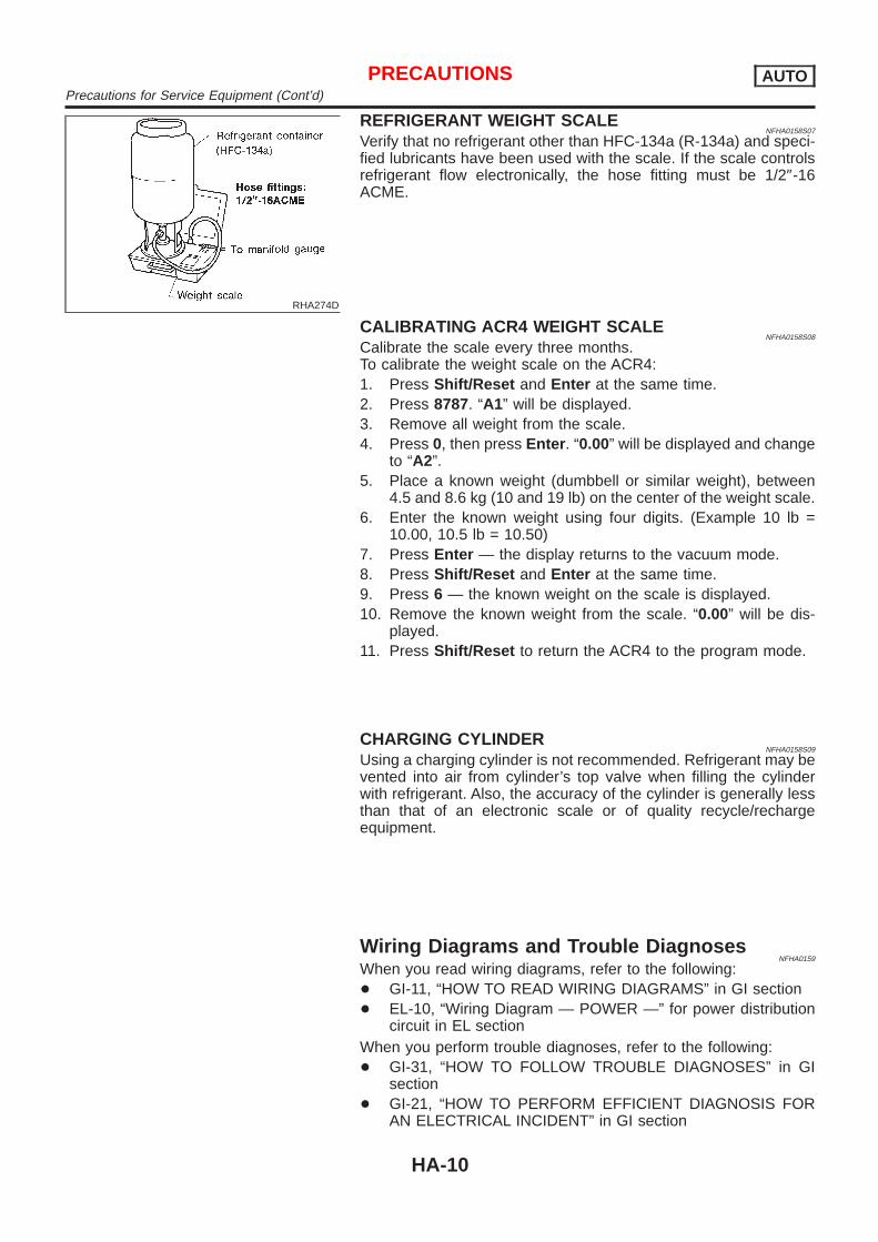
REFRIGERANT WEIGHT SCALENFHA0158S07
Verify that no refrigerant other than HFC-134a (R-134a) and speci-fied lubricants have been used with the scale. If the scale controlsrefrigerant flow electronically, the hose fitting must be 1/2″-16ACME.
CALIBRATING ACR4 WEIGHT SCALENFHA0158S08
Calibrate the scale every three months.To calibrate the weight scale on the ACR4:1. Press Shift/Reset and Enter at the same time.2. Press 8787. “A1” will be displayed.3. Remove all weight from the scale.4. Press 0, then press Enter . “0.00” will be displayed and change
to “A2”.5. Place a known weight (dumbbell or similar weight), between
4.5 and 8.6 kg (10 and 19 lb) on the center of the weight scale.6. Enter the known weight using four digits. (Example 10 lb =
10.00, 10.5 lb = 10.50)7. Press Enter — the display returns to the vacuum mode.8. Press Shift/Reset and Enter at the same time.9. Press 6 — the known weight on the scale is displayed.10. Remove the known weight from the scale. “0.00” will be dis-
played.11. Press Shift/Reset to return the ACR4 to the program mode.
CHARGING CYLINDERNFHA0158S09
Using a charging cylinder is not recommended. Refrigerant may bevented into air from cylinder’s top valve when filling the cylinderwith refrigerant. Also, the accuracy of the cylinder is generally lessthan that of an electronic scale or of quality recycle/rechargeequipment.
Wiring Diagrams and Trouble DiagnosesNFHA0159
When you read wiring diagrams, refer to the following:+ GI-11, “HOW TO READ WIRING DIAGRAMS” in GI section+ EL-10, “Wiring Diagram — POWER —” for power distribution
circuit in EL sectionWhen you perform trouble diagnoses, refer to the following:+ GI-31, “HOW TO FOLLOW TROUBLE DIAGNOSES” in GI
section+ GI-21, “HOW TO PERFORM EFFICIENT DIAGNOSIS FOR
AN ELECTRICAL INCIDENT” in GI section
PRECAUTIONS AUTOPrecautions for Service Equipment (Cont’d)
HA-10

Special Service ToolsNFHA0160
Tool numberTool name
Description
KV99106100Clutch disc wrench
NT232
Removing center bolt
NT378
KV99232340orKV992T0001Clutch disc puller
NT376
Removing clutch disc
KV99106200Pulley installer
NT235
Installing pulley
PREPARATION AUTOSpecial Service Tools
HA-11

HFC-134a (R-134a) Service Tools andEquipment
=NFHA0161
Never mix HFC-134a refrigerant and/or its specified lubricant with CFC-12 (R-12) refrigerant and/or its lubri-cant.Separate and non-interchangeable service equipment must be used for handling each type of refrigerant/lubricant.Refrigerant container fittings, service hose fittings and service equipment fittings (equipment which handlesrefrigerant and/or lubricant) are different between CFC-12 (R-12) and HFC-134a (R-134a). This is to avoidmixed use of the refrigerants/lubricant.Adapters that convert one size fitting to another must never be used: refrigerant/lubricant contamination willoccur and compressor failure will result.
Tool numberTool name
Description
HFC-134a (R-134a)refrigerant
NT196
Container color: Light blueContainer marking: HFC-134a (R-134a)Fitting size: Thread size+ Large container 1/2″-16 ACME
KLH00-PAGS0Nissan A/C System OilType S
NT197
Type: Poly alkylene glycol oil (PAG), type SApplication: HFC-134a (R-134a) swash plate (pis-ton) compressors (Nissan only)Lubricity: 40 m! (1.4 Imp fl oz)
Recovery/RecyclingRecharging equipment(ACR4)
NT195
Function: Refrigerant Recovery and Recycling andRecharging
Electrical leak detector
NT198
Power supply:+ DC 12V (Cigarette lighter)
(J-43926)Refrigerant dye leakdetection kitKit includes:(J-42220) UV lamp andUV safety glasses(J-41459) Refrigerantdye injector(J-41447) qty. 24R-134a refrigerant dye(J-43872) Refrigerantdye cleaner
SHA437F
Power supply:DC 12V (Battery terminal)
PREPARATION AUTOHFC-134a (R-134a) Service Tools and Equipment
HA-12

Tool numberTool name
Description
(J-42220)Fluorescent dye leakdetector
UV lamp UV safety glasses
SHA438F
Power supply: DC12V (Battery terminal)For checking refrigerant leak when fluorescent dyeis installed in A/C system.Includes: UV lamp and UV safety glasses
(J-41447)R134a Fluorescent LeakDetection Dye (Box of24, 1/4 ounce bottles)
Dye
SHA439F
Application: For R-134a PAG oilContainer: 1/4 ounce (7.4 cc) bottle(Includes self-adhesive dye identification labels foraffixing to vehicle after charging system with dye.)
(J-41459)R134a Dye InjectorUse with J-41447, 1/4ounce bottle
Dye injector
SHA440F
For injecting 1/4 ounce of Fluorescent Leak Detec-tion Dye into A/C system.
(J-43872)Dye cleaner
SHA441F
For cleaning dye spills.
Manifold gauge set (withhoses and couplers)
NT199
Identification:+ The gauge face indicates R-134a.Fitting size: Thread size+ 1/2″-16 ACME
Service hoses+ High side hose+ Low side hose+ Utility hose
NT201
Hose color:+ Low hose: Blue with black stripe+ High hose: Red with black stripe+ Utility hose: Yellow with black stripe or green
with black stripeHose fitting to gauge:+ 1/2″-16 ACME
Service couplers+ High side coupler+ Low side coupler
NT202
Hose fitting to service hose:+ M14 x 1.5 fitting is optional or permanently
attached.
PREPARATION AUTOHFC-134a (R-134a) Service Tools and Equipment (Cont’d)
HA-13

Tool numberTool name
Description
Refrigerant weight scale
NT200
For measuring of refrigerantFitting size: Thread size+ 1/2″-16 ACME
Vacuum pump(Including the isolatorvalve)
NT203
Capacity:+ Air displacement: 4 CFM+ Micron rating: 20 microns+ Oil capacity: 482 g (17 oz)Fitting size: Thread size+ 1/2″-16 ACME
PREPARATION AUTOHFC-134a (R-134a) Service Tools and Equipment (Cont’d)
HA-14

Refrigeration SystemREFRIGERATION CYCLE
NFHA0162
Refrigerant FlowNFHA0162S01
The refrigerant flows in the standard pattern, that is, through the compressor, the condenser, the liquid tank,through the evaporator, and back to the compressor. The refrigerant evaporation through the evaporator coilis controlled by an externally equalized expansion valve, located inside the evaporator case.
Freeze ProtectionNFHA0162S02
Under normal operating conditions, when the A/C is switched on, the compressor runs continuously, and theevaporator pressure, and therefore, temperature is controlled by the V-6 variable displacement compressor toprevent freeze up.
Refrigerant System ProtectionNFHA0162S03
Refrigerant Pressure SensorNFHA0162S0301
The refrigerant system is protected against excessively high or low pressures by the refrigerant pressuresensor, located on the liquid tank. If the system pressure rises above, or falls below the specifications, therefrigerant pressure sensor detects the pressure inside the refrigerant line and sends the voltage signal to theECM. ECM makes the A/C relay go OFF and stops the compressor when pressure on the high pressure sidedetected by refrigerant pressure sensor is over about 2,746 kPa (27.5 bar, 28 kg/cm2, 398 psi), or below about177 kPa (1.77 bar, 1.8 kg/cm2, 26 psi).Pressure Relief Valve
NFHA0162S0302
The refrigerant system is also protected by a pressure relief valve, located in the rear head of the compres-sor. When the pressure of refrigerant in the system increases to an abnormal level [more than 3,727 kPa (37.3bar, 38 kg/cm2, 540 psi)], the release port on the pressure relief valve automatically opens and releasesrefrigerant into the atmosphere.
RHA347H
DESCRIPTION AUTORefrigeration System
HA-15

V-6 Variable Displacement CompressorGENERAL INFORMATION
=NFHA0163
1. The V-6 variable compressor differs from previous units. The vent temperatures of the V-6 variable com-press do not drop too far below 5°C (41°F) when:
+ evaporator intake air temperature is less than 20°C (68°F)+ engine is running at speeds less than 1,500 rpm.
This is because the V-6 compressor provides a means of “capacity” control.2. The V-6 variable compressor provides refrigerant control under varying conditions. During cold winters, it
may not produce high refrigerant pressure discharge (compared to previous units) when used with airconditioning systems.
3. A “clanking” sound may occasionally be heard during refrigerant charge. The sound indicates that the tiltangle of the swash plate has changed and is not a problem.
4. For air conditioning systems with the V-6 compressor, the clutch remains engaged unless: the system mainswitch, fan switch or ignition switch is turned OFF. When ambient (outside) temperatures are low or whenthe amount of refrigerant is insufficient, the clutch is disengaged to protect the compressor.
5. A constant range of suction pressure is maintained when engine speed is greater than a certain value. Itnormally ranges from 147 to 177 kPa (1.47 to 1.77 bar, 1.5 to 1.8 kg/cm2, 21 to 26 psi) under varying con-ditions.In previous compressors, however, suction pressure was reduced with increases in engine speed.
DESCRIPTION AUTOV-6 Variable Displacement Compressor
HA-16

DESCRIPTION=NFHA0164
GeneralNFHA0164S01
The variable compressor is basically a swash plate type that changes piston stroke in response to the requiredcooling capacity.The tilt of the swash plate allows the piston’s stroke to change so that refrigerant discharge can be continu-ously changed from 14.5 to 184 cm3 (0.885 to 11.228 cu in).
RHA037DD
DESCRIPTION AUTOV-6 Variable Displacement Compressor (Cont’d)
HA-17

Operation=NFHA0164S02
1. Operation Control ValveNFHA0164S0201
Operation control valve is located in the suction port (low-pressure) side, and opens or closes in response tochanges in refrigerant suction pressure.Operation of the valve controls the internal pressure of the crankcase.The angle of the swash plate is controlled between the crankcase’s internal pressure and the piston cylinderpressure.2. Maximum Cooling
NFHA0164S0202
Refrigerant pressure on the low-pressure side increases with an increase in heat loads.When this occurs, the control valve’s bellows compress to open the low-pressure side valve and close thehigh-pressure side valve.This causes the following pressure changes:+ the crankcase’s internal pressure to equal the pressure on the low-pressure side;+ the cylinder’s internal pressure to be greater than the crankcase’s internal pressure.Under this condition, the swash plate is set to the maximum stroke position.
RHA473C
DESCRIPTION AUTOV-6 Variable Displacement Compressor (Cont’d)
HA-18

3. Capacity Control=NFHA0164S0203
+ Refrigerant pressure on suction side is low during high speed driving or when ambient or interior tempera-ture is low.
+ The bellows expands when refrigerant pressure on the suction pressure side drops below approximately177 kPa (1.77 bar, 1.8 kg/cm2, 26 psi).Since suction pressure is low, it makes the suction port close and the discharge port open. Thus, crank-case pressure becomes high as high pressure enters the crankcase.
+ The force acts around the journal pin near the swash plate, and is generated by the pressure differencebefore and behind the piston.The drive lug and journal pin are located where the piston generates the highest pressure. Piston pres-sure is between suction pressure Ps and discharge pressure Pd, which is near suction pressure Ps. Ifcrankcase pressure Pc rises due to capacity control, the force around the journal pin makes the swashplate angle decrease and also the piston stroke decrease. In other words, crankcase pressure increasetriggers pressure difference between the piston and the crankcase. The pressure difference changes theangle of the swash plate.
RHA474C
DESCRIPTION AUTOV-6 Variable Displacement Compressor (Cont’d)
HA-19

IACV-AAC CONTROL SYSTEM=NFHA0165
OperationNFHA0165S02
When the air conditioner is OFF, the ECM detects the load applied to the engine, and controls the IACV-AACvalve to adjust the engine idling speed to the appropriate rpm by supplying additional air from the IACV-AACvalve.When the air conditioner is ON (A/C relay is ON), refrigerant-pressure sensor converts refrigeration-pressureon the high pressure side into the voltage value, which is output to ECM which protects refrigeration cycle andcontrol idle speed by the output voltage data, and additional air is supplied to the engine. If the appropriateengine speed is not reached, the IACV-AAC valve supplies the additional air required to increase the enginerpm.
DESCRIPTION AUTOV-6 Variable Displacement Compressor (Cont’d)
HA-20

Component LayoutNFHA0166
RHA349HA
DESCRIPTION AUTOComponent Layout
HA-21

IntroductionNFHA0167
AIR CONDITIONER LAN SYSTEM OVERVIEW CONTROL SYSTEMNFHA0167S01
The LAN system consists of auto amp., mode door motor, air mix door motor and intake door motor.A configuration of these components is shown in the diagram below.
RHA439GB
FeaturesNFHA0168
SYSTEM CONSTRUCTION (LAN)NFHA0168S01
A small network is constructed between the auto amplifier, mode door motor, air mix door motor and intakedoor motor. The auto amplifier and motors are connected by data transmission lines and motor power supplylines. The LAN network is built through the ground circuits of the three motors.Addresses, motor opening angle signals, motor stop signals and error checking messages are all transmittedthrough the data transmission lines connecting the auto amplifier and three motors.The following functions are contained in LCUs built into the mode door motor, air mix door motor and the intakedoor motor.+ Address+ Motor opening angle signals+ Data transmission+ Motor stop and drive decision+ Opening angle sensor (PBR function)+ Comparison+ Decision (Auto amplifier indicated value and motor opening angle comparison)
RHA350H
OperationNFHA0168S0101
The auto amplifier receives data from each of the sensors. The amplifier sends mode door, air mix door andintake door opening angle data to the mode door motor LCU, air mix door LCU and intake door motor LCU.The mode door motor, air mix door motor and intake door motor read their respective signals according to theaddress signal. Opening angle indication signals received from the auto amplifier and each of the motor posi-tion sensors are compared by the LCUs in each motor with the existing decision and opening angles.Subsequently, HOT/COLD, FRESH/RECIRCULATION or DEFROST/VENT operation is selected. The newselection data is returned to the auto amplifier.
DESCRIPTION AUTOIntroduction
HA-22

RHA351H
Transmission Data and Transmission OrderNFHA0168S0102
Amplifier data is transmitted consecutively to each of the door motors following the form shown in figure below.Start: Initial compulsory signal sent to each of the door motors.Address: Data sent from the auto amplifier is selected according to data-based decisions made by the modedoor motor, air mix door motor and intake door motor.If the addresses are identical, the opening angle data and error check signals are received by the door motorLCUs. The LCUs then make the appropriate error decision. If the opening angle data is normal, door controlbegins.If an error exists, the received data is rejected and corrected data received. Finally, door control is based uponthe corrected opening angle data.Opening angle: Data that shows the indicated door opening angle of each door motor.Error check: Procedure by which sent and received data is checked for errors. Error data is then compiled.The error check prevents corrupted data from being used by the mode door motor, air mix door motor andintake door motor. Error data can be related to the following problems.+ Abnormal electrical frequency+ Poor electrical connections+ Signal leakage from transmission lines+ Signal level fluctuationStop signal: At the end of each transmission, a stop operation, in-operation, or internal problem message isdelivered to the auto amplifier. This completes one data transmission and control cycle.
RHA352H
Air Mix Door Control (Automatic Temperature Control)NFHA0168S0103
The air mix door is automatically controlled so that in-vehicle temperature is maintained at a predeterminedvalue by: The temperature setting, ambient temperature, in-vehicle temperature and amount of sunload.
DESCRIPTION AUTOFeatures (Cont’d)
HA-23

Fan Speed ControlNFHA0168S0104
Blower speed is automatically controlled based on temperature setting, ambient temperature, in-vehicletemperature, intake temperature, amount of sunload and air mix door position.With FAN switch set to “AUTO”, the blower motor starts to gradually increase air flow volume.When engine coolant temperature is low, the blower motor operation is delayed to prevent cool air from flow-ing.
Intake Door ControlNFHA0168S0105
The intake doors are automatically controlled based on temperature setting, ambient temperature, in-vehicletemperature, intake temperature, amount of sunload, air mix door position and ON-OFF operation of the com-pressor.
Outlet Door ControlNFHA0168S0106
The outlet door is automatically controlled by: The temperature setting, ambient temperature, in-vehicletemperature, intake temperature and amount of sunload.
Magnet Clutch ControlNFHA0168S0107
The ECM controls compressor operation using input signals from the throttle position sensor, refrigerant pres-sure sensor and auto amplifier.
Self-diagnostic SystemNFHA0168S0108
The self-diagnostic system is built into the auto amplifier (LCU) to quickly locate the cause of problems.
DESCRIPTION AUTOFeatures (Cont’d)
HA-24

Overview of Control System=NFHA0169
The control system consists of input sensors, switches, the automatic amplifier (microcomputer) and outputs.The relationship of these components is shown in the diagram below:
RHA550HA
Control OperationNFHA0170
SHA467F
DESCRIPTION AUTOOverview of Control System
HA-25

SHA466F
DISPLAY SCREENNFHA0170S01
Displays the operational status of the system.
AUTO SWITCHNFHA0170S02
The compressor, intake doors, air mix door, outlet doors, and blower speed are automatically controlled sothat the in-vehicle temperature will reach, and be maintained at the set temperature selected by the operator.RHD models:Pressing the AUTO switch illuminates the A/C switch indicator (RHD) when the A/C switch is ON before theAUTO switch is pressed, and turns ON the compressor.
ECON SWITCH (LHD MODELS)NFHA0170S03
By pressing the ECON switch, the display should indicate ECON and the compressor always turns OFF. Withthe compressor OFF, the system will not remove heat (cool) or de-humidify. The system will maintain the in-vehicle temperature at the set temperature when the set temperature is above the ambient (outside) tempera-ture. The system will set the intake doors to the outside air position.
TEMPERATURE DIAL (POTENTIO TEMPERATURE CONTROL)NFHA0170S04
Increases or decreases the set temperature.
OFF SWITCHNFHA0170S05
The compressor and blower are OFF, the intake doors are set to the outside air position, and the air outletdoors are set to the foot (80% foot and 20% defrost) position.
FAN SWITCHNFHA0170S06
Manual control of the blower speed. Four speeds are available for manual control (as shown on the displayscreen):low , medium low , medium high , high
FRESH SWITCH (RHD MODELS)NFHA0170S11
OFF position: Interior air is recirculated inside the vehicle.ON position: Outside air is drawn into the passenger compartment.(When RECIRCULATION switch is ON, the FRESH switch turns OFF automatically.)
A/C SWITCH (RHD MODELS)NFHA0170S12
The compressor is ON or OFF.(Pressing the A/C switch when the AUTO switch is ON will turn off the A/C switch and compressor.)
DESCRIPTION AUTOControl Operation (Cont’d)
HA-26

RECIRCULATION (REC) SWITCHNFHA0170S07
OFF position: Outside air is drawn into the passenger compartment.ON position: Interior air is recirculated inside the vehicle.(When the FRESH switch is ON (RHD models) or the compressor is turned from ON to OFF, the RECIRCU-LATION switch turns OFF) automatically.
DEFROSTER (DEF) SWITCHNFHA0170S08
Positions the air outlet doors to the defrost position. Also positions the intake doors to the outside air position.
MODE SWITCHESNFHA0170S09
Control the air discharge outlets.
REAR WINDOW DEFOGGER SWITCHNFHA0170S10
When illumination is ON, rear window is defogged.
DESCRIPTION AUTOControl Operation (Cont’d)
HA-27
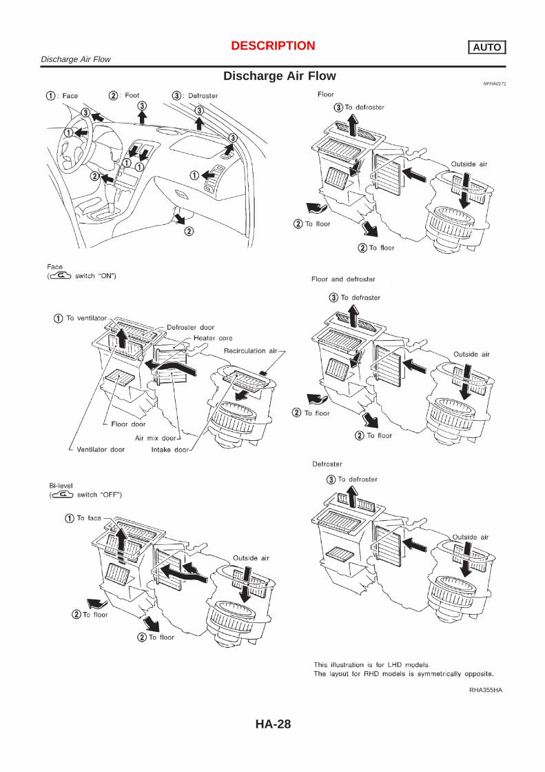
Discharge Air FlowNFHA0171
RHA355HA
DESCRIPTION AUTODischarge Air Flow
HA-28
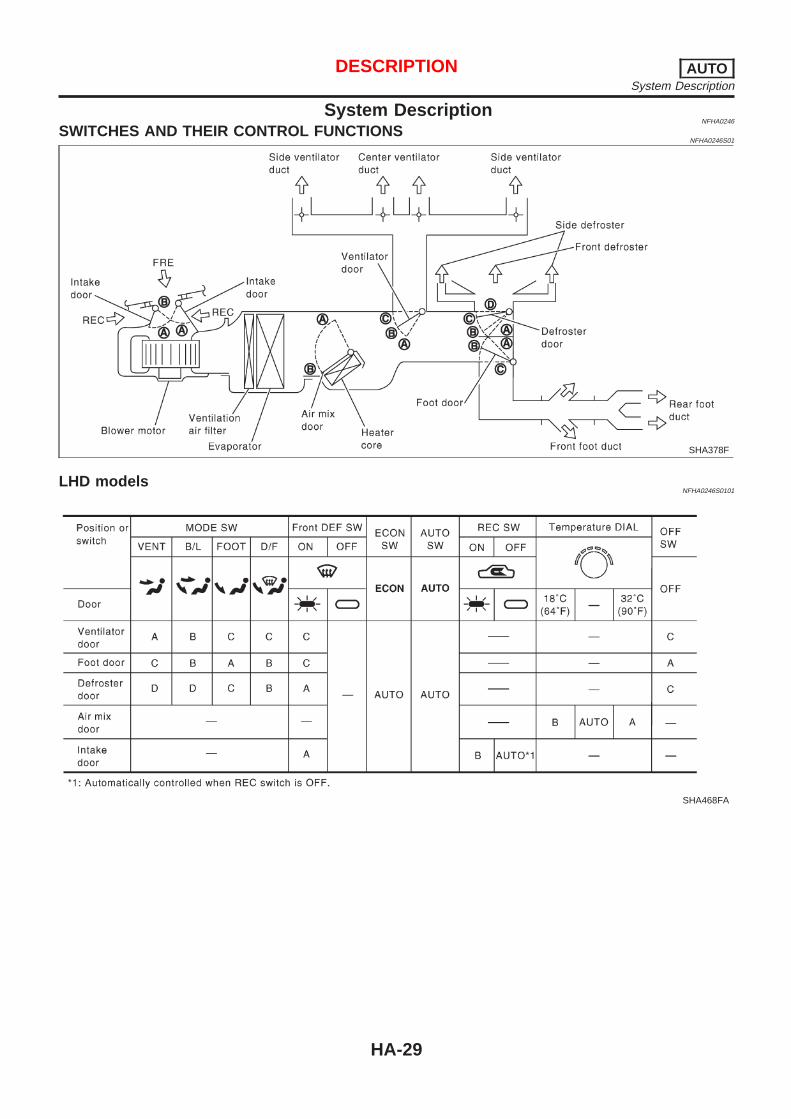
System DescriptionNFHA0246
SWITCHES AND THEIR CONTROL FUNCTIONSNFHA0246S01
SHA378F
LHD modelsNFHA0246S0101
SHA468FA
DESCRIPTION AUTOSystem Description
HA-29

RHD modelsNFHA0246S0102
SHA569F
DESCRIPTION AUTOSystem Description (Cont’d)
HA-30

Component LocationNFHA0172
ENGINE COMPARTMENTNFHA0172S01
RHA453H
TROUBLE DIAGNOSES AUTOComponent Location
HA-31

PASSENGER COMPARTMENTNFHA0172S02
RHA454HA
TROUBLE DIAGNOSES AUTOComponent Location (Cont’d)
HA-32

Circuit DiagramNFHA0173
MHA970A
TROUBLE DIAGNOSES AUTOCircuit Diagram
HA-33

Wiring Diagram — A/C, A —NFHA0174
MHA995A
TROUBLE DIAGNOSES AUTOWiring Diagram — A/C, A —
HA-34
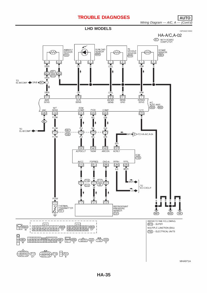
LHD MODELS=NFHA0174S01
MHA971A
TROUBLE DIAGNOSES AUTOWiring Diagram — A/C, A — (Cont’d)
HA-35

RHD MODELS=NFHA0174S02
MHA972A
TROUBLE DIAGNOSES AUTOWiring Diagram — A/C, A — (Cont’d)
HA-36

MHA945A
TROUBLE DIAGNOSES AUTOWiring Diagram — A/C, A — (Cont’d)
HA-37

RHA962H
Auto Amp. Terminals and Reference ValueNFHA0175
INSPECTION OF AUTO AMP.NFHA0175S01
+ Measure voltage between each terminal and body ground byfollowing “AUTO AMP. INSPECTION TABLE”.
+ Pin connector terminal layout
RHA501GC
AUTO AMP. INSPECTION TABLENFHA0175S02
TERMINALNO.
ITEM CONDITIONVoltage
V
1 Intake sensor — —
2 Ambient sensor — —
3 In-vehicle sensor — —
8 ECM COMPCompressor ON Approximately 0
Compressor OFF Approximately 4.6
11 Sensor ground — Approximately 0
12 Sunload sensor — —
13 Thermal transmitterEngine coolant
temperature
Approximately 40°C (104°F) Approximately 10.8
Approximately 55°C (131°F) Approximately 9.9
Approximately 60°C (140°F) Approximately 9.5
14 Ground — Approximately 0
16 A/C LAN signal — Approximately 5.5
21Power supply for mode doormotor, intake door motor and
air mix door motor— Approximately 12
22 Compressor ON signal CompressorON Approximately 0
OFF Approximately 4.6
23 FICD ON signalAmbient tempera-
ture
Less than −1°C (30°F) Approximately 5
More than 0°C (32°F) Approximately 0
TROUBLE DIAGNOSES AUTOAuto Amp. Terminals and Reference Value
HA-38

TERMINALNO.
ITEM CONDITIONVoltage
V
26 Power supply for BAT — BATTERY VOLTAGE
27 Power supply for IGN — Approximately 12
28Ambient temperature signal
(With board computer)— Approximately 4.5
30Rear window defogger feed
backRear window
defogger switch
ON Approximately 12
OFF Approximately 0
31Rear window defogger ON sig-
nalRear window
defogger switch
ON Approximately 0
OFF Approximately 12
32 Ground — Approximately 0
33 Power source for A/C Ignition voltage feed back Approximately 12
34 Blower motor feed back Fan speed: Low Approximately 7 - 10
35 Fan control AMP. control signal Fan speed
Low, Middle low or Middlehigh
Approximately 2.5 -3.0
High Approximately 9 - 10
TROUBLE DIAGNOSES AUTOAuto Amp. Terminals and Reference Value (Cont’d)
HA-39

Self-diagnosis=NFHA0176
INTRODUCTION AND GENERAL DESCRIPTIONNFHA0176S01
The self-diagnostic system diagnoses sensors, door motors, blower motor, etc. by system line. Refer to appli-cable sections (items) for details. Shifting from normal control to the self-diagnostic system is accomplishedby starting the engine (turning the ignition switch from “OFF” to “ON”) and pressing “ ” switch for at least5 seconds. The “ ” switch must be pressed within 10 seconds after starting the engine (ignition switch isturned “ON”). This system will be canceled by either pressing (AUTO) switch or turning the ignition switch“OFF”. Shifting from one step to another is accomplished by means of pushing TEMP dial right turn or TEMPdial left turn switch, as required.Additionally shifting from STEP 5 to AUXILIARY MECHANISM is accomplished by means of pushing (fan)UP switch.
SHA469F
Perform all of the following tests to narrow the problem to a specific assembly, actuator, or function.Link to the Diagnostic Procedure which corresponds to malfunctions noted in these tests.If the A/C display screen has no display, check all power supply circuits to the A/C Auto Amp.
TROUBLE DIAGNOSES AUTOSelf-diagnosis
HA-40

FUNCTION CONFIRMATION PROCEDURENFHA0176S02
1 ENTER SELF-DIAGNOSTIC MODE
Perform steps 1 - 31. Turn the ignition OFF.2. Start the engine.3. Immediately after starting the engine press and hold the OFF switch (for the auto A/C system) for at least 5 seconds.The A/C Auto Amp. should now be in Self Diagnosis mode. Self Diagnosis steps 1 - 5 can now be performed. Self Diagno-sis step 1 will be displayed first. Shifting from one step to another is accomplished by pressing the temperature increaseor decrease switch.
© GO TO 2.
2 STEP 1 LED/DISPLAY CHECK
Verify all segments illuminate.If all segments do not illuminate the fluorescent display tube is malfunctioning or the system has not entered self diagnosiswhich would indicate a malfunctioning OFF switch.Do all LEDs and segments illuminate?
SHA470F
Yes or No
Yes © GO TO 3.
No © Malfunctioning switch, LED or fluorescent display tube.Replace A/C auto amp.
3 CHECK TO ADVANCE SELF-DIAGNOSIS STEP 2
1. Turn the TEMP dial clockwise.2. Advance to self-diagnosis STEP 2.If the system does not shift between step 1 and 2 a malfunctioning TEMP dial is indicated.
Yes or No
Yes © GO TO 4.
No © Malfunctioning TEMP dial.Replace A/C auto amp.
TROUBLE DIAGNOSES AUTOSelf-diagnosis (Cont’d)
HA-41

4 CHECK TO RETURN SELF-DIAGNOSIS STEP 1
1. Turn the TEMP dial counterclockwise.2. Return to self-diagnosis STEP 1.If the system does not shift between step 1 and 2 a malfunctioning TEMP dial is indicated.
Yes or No
Yes © GO TO 5.
No © Malfunctioning TEMP dial.Replace A/C auto amp.
5 STEP 2 - SENSOR CIRCUITS ARE CHECKED FOR OPEN OR SHORT CIRCUIT
Turn the TEMP dial clockwise, advance to STEP 2: Wait (about 25 seconds) for two digit Code to appear.This is the Electronic Sensor Input Check which includes circuits.Does code No. appear on the display?
RHA970DB
Yes or No
Yes © GO TO 6.
No © GO TO 13.
6 STEP 3 - MODE DOOR AND INTAKE DOOR POSITIONS ARE CHECKED
Turn the TEMP dial clockwise, advance to STEP 3. Wait (about 50 seconds) for two digit Code to appear.This is the Mode Door and Intake Door Position Switch input checks including circuits.Does code No. appear on the display?
RHA869DD
Yes or No
Yes © GO TO 7.
No © GO TO 14.
TROUBLE DIAGNOSES AUTOSelf-diagnosis (Cont’d)
HA-42

7 STEP 4 - OPERATION OF EACH ACTUATOR IS CHECKED
Turn the TEMP dial clockwise, advance to STEP 4.Engine running.This is Heater and A/C system check. Code 41 will be displayed. Use the DEF switch to advance the code number from41 to 46. After 46, the display will return to code 41 and can be advanced to 46 again.
RHA495A
© GO TO 8.
TROUBLE DIAGNOSES AUTOSelf-diagnosis (Cont’d)
HA-43

8 CHECK ACTUATORS
Confirm operation of system components according to the following charts.Checks must be made visually, by listening to any noise, or by touching air outlets with your hand, etc. forimproper operation.
MTBL0394
Operating condition of each actuator cannot be checked by indicators.
MTBL0128
OK or NG
OK © GO TO 9.
NG © + Air outlet does not change.Go to “Mode Door Motor” (HA-57).
+ Intake door does not change.Go to “Intake Door Motor” (HA-66).
+ Blower motor operation is malfunctioning.Go to “Blower Motor” (HA-69).
+ Magnet clutch does not engage.Go to “Magnet Clutch” (HA-77).
+ Discharge air temperature does not change.Go to “Air Mix Door Motor” (HA-63).
TROUBLE DIAGNOSES AUTOSelf-diagnosis (Cont’d)
HA-44

9 STEP 5 - TEMPERATURE OF EACH SENSOR IS CHECKED
Turn the TEMP dial clockwise, advance to STEP 5. This is Intake sensor, In Vehicle sensor and Ambient Sensor functioncheck. Code 51 will be displayed.NOTE:Each sensor reading should be approximately the actual temperature.
RHA359H
© GO TO 10.
10 CHECK AMBIENT SENSOR
Press DEF once, temperature detected by the Ambient Sensor is displayed.
RHA551H
OK or NG
OK © GO TO 11.
NG © Go to Ambient Sensor Circuit (HA-95).
11 CHECK IN-VEHICLE SENSOR
Press DEF second time, temperature detected by the In Vehicle Sensor is displayed.
RHA552H
OK or NG
OK © GO TO 12.
NG © Go to In-vehicle Sensor Circuit (HA-98).
TROUBLE DIAGNOSES AUTOSelf-diagnosis (Cont’d)
HA-45

12 CHECK INTAKE SENSOR
Press DEF third time, temperature detected by the Intake Sensor is displayed.
RHA553H
OK or NG
OK © 1. Press (DEF) switch the fourth time. Display returns to original presentation 51.2. Turn ignition switch OFF or (AUTO) switch ON.3. END
NG © Go to Intake Sensor Circuit (HA-105).
TROUBLE DIAGNOSES AUTOSelf-diagnosis (Cont’d)
HA-46

13 CHECK MALFUNCTIONING SENSOR
NOTE:+ A blinking mark (-) preceding the Code No. indicates a short circuit.+ If 2 or more items are malfunctioning the corresponding codes will alternately blink twice.+ A circuit will be detected as open or shorted and its code No. will be displayed when input signals correspond with con-
ditions in the following chart.
MTBL0401
*1: “95%” and “5%” refer to percentage with respect to stroke of air mix door. (Full cold: 0%, Full hot: 100%)*2: Conduct self-diagnosis STEP 2 under sunshine.When conducting indoors, direct light (more than 60W) at sunload sensor.*3: HA-95, *4: HA-98, *5: HA-105, *6: HA-102, *7: HA-108
RHA455G
RHA501A
© INSPECTION END
TROUBLE DIAGNOSES AUTOSelf-diagnosis (Cont’d)
HA-47

14 CHECK MALFUNCTIONING DOOR MOTOR POSITION SWITCH
30- Mode door and intake door position switches are in working order.Continue to next step.31- Mode door circuit / switch in vent position switch is malfunctioning.32- Mode door circuit / switch in B/L position switch is malfunctioning.34- Mode door circuit / switch in Foot position switch is malfunctioning.35- Mode door circuit / switch in Foot Def. position switch is malfunctioning.36- Mode door circuit / switch in Def. position switch is malfunctioning.37- Intake door mode circuit / switch in Fresh Air position is malfunctioning.38- Intake door mode circuit / switch in 20% Fresh Air position is malfunctioning.39- Intake door mode circuit / switch in Recirculation Air position is malfunctioning.NOTE:+ If 2 or more items are malfunctioning the corresponding codes will alternately blink twice.+ If the Mode Door Motor harness is disconnected repeated display pattern of 31 → 32 → 34 → 35 → 36 will occur.+ If Intake Door Motor harness is disconnected repeated display pattern of 37 → 38 → 39 will occur.+ If any Mode Door Motor Position Switch is malfunctioning the Mode Door Motor will also malfunction.
RHA168DA
RHA498A
© INSPECTION END
TROUBLE DIAGNOSES AUTOSelf-diagnosis (Cont’d)
HA-48

AUXILIARY MECHANISM: TEMPERATURE SETTING TRIMMER=NFHA0176S03
Unconfirmed IncidentsNFHA0176S0301
The customer may feel that the cabin temperature is not being controlled or regulated to the temperature indi-cated by the auto A/C display screen. To satisfy individual driver preference the Temperature Setting Trimmermay be used to compensate in a range of ±3°C (±6°F).1. Enter Self Diagnosis mode and select STEP 5.2. Press the Fan Up switch: This will set the A/C system in auxiliary mode and the display will show 61.3. Turn the temperature dial clockwise or counterclockwise: The temperature will change at a rate of 0.5°C
(1°F).If power is lost to the A/C Auto Amp., trimmer setting is canceled and setting becomes that of initial condition,0°.
SHA465F
When battery cable is disconnected, trimmer operation is canceled. Temperature set becomes that ofinitial condition, i.e. 0°C (0°F).
TROUBLE DIAGNOSES AUTOSelf-diagnosis (Cont’d)
HA-49

How to Perform Trouble Diagnoses for Quickand Accurate Repair
=NFHA0177
WORK FLOWNFHA0177S01
SHA900E
*1: Operational Check (HA-51)
SYMPTOM TABLENFHA0177S02
Symptom Reference Page
+ A/C system does not come on. + Go to Trouble Diagnosis Procedure for A/C system. HA-54
+ Air outlet does not change.
+ Go to Trouble Diagnosis Procedure for Mode Door Motor. (LAN) HA-57+ Mode door motor does not operate nor-mally.
+ Discharge air temperature does notchange.
+ Go to Trouble Diagnosis Procedure for Air Mix Door Motor. (LAN) HA-63+ Air mix door motor does not operate nor-
mally.
+ Intake door does not change.
+ Go to Trouble Diagnosis Procedure for Intake Door Motor. (LAN) HA-66+ Intake door motor does not operate nor-mally.
+ Blower motor operation is malfunctioning.
+ Go to Trouble Diagnosis Procedure for Blower Motor. HA-69+ Blower motor operation is malfunctioningunder out of starting fan speed control.
+ Magnet clutch does not engage. + Go to Trouble Diagnosis Procedure for Magnet Clutch. HA-77
+ Insufficient cooling. + Go to Trouble Diagnosis Procedure for Insufficient Cooling. HA-83
+ Insufficient heating. + Go to Trouble Diagnosis Procedure for Insufficient Heating. HA-91
+ Noise. + Go to Trouble Diagnosis Procedure for Noise. HA-92
+ Self-diagnosis can not be performed. + Go to Trouble Diagnosis Procedure for Self-diagnosis. HA-93
+ Memory function does not operate. + Go to Trouble Diagnosis Procedure for Memory Function. HA-94
+ ECON mode does not operate.+ Go to Trouble Diagnosis Procedure for ECON (ECONOMY) —
mode.HA-95
TROUBLE DIAGNOSES AUTOHow to Perform Trouble Diagnoses for Quick and Accurate Repair
HA-50

Operational CheckNFHA0178
The purpose of the operational check is to confirm that the systemoperates properly.
CONDITIONS:NFHA0178S01
+ Engine running and at normal operating temperature.
RHA964H
PROCEDURE:NFHA0178S02
1. Check Memory FunctionNFHA0178S0201
1. Set the temperature 90°F or 32°C.2. Press OFF switch.3. Turn the ignition off.4. Turn the ignition on.5. Press the AUTO switch.6. Confirm that the set temperature remains at previous tempera-
ture.7. Press OFF switch.If NG, go to trouble diagnosis procedure for memory function (HA-94).If OK, continue with next check.
RHA002I
2. Check BlowerNFHA0178S0202
1. Press fan switch (up side) one time.Blower should operate on low speed.The fan symbol should have one blade lit .
2. Press fan switch (up side) one more time, and continue check-ing blower speed and fan symbol until all speeds are checked.
3. Leave blower on MAX speed .If NG, go to trouble diagnosis procedure for blower motor (HA-69).If OK, continue with next check.
RHA003I
3. Check Discharge AirNFHA0178S0203
1. Press mode switch four times and DEF button.2. Each position indicator should change shape.
TROUBLE DIAGNOSES AUTOOperational Check
HA-51

RHA654F
3. Confirm that discharge air comes out according to the air dis-tribution table at left.Refer to “Discharge Air Flow” (HA-28).
NOTE:Confirm that the compressor clutch is engaged (visual inspection)and intake door position is at FRESH when the DEF isselected.Intake door position is checked in the next step.If NG, go to trouble diagnosis procedure for mode door motor(HA-57).If OK, continue with next check.
RHA965H
4. Check RecirculationNFHA0178S0204
1. Press REC switch.Recirculation indicator should illuminate.
2. Listen for intake door position change (you should hear blowersound change slightly).
If NG, go to trouble diagnosis procedure for intake door (HA-66).If OK, continue with next check.
RHA966H
5. Check Temperature DecreaseNFHA0178S0205
1. Turn the temperature dial counterclockwise until 18°C (64°F)is displayed.
2. Check for cold air at discharge air outlets.If NG, go to trouble diagnosis procedure for insufficient cooling(HA-83).If OK, continue with next check.
RHA967H
6. Check Temperature IncreaseNFHA0178S0206
1. Turn the temperature dial clockwise until 32°C (90°F) is dis-played.
2. Check for hot air at discharge air outlets.If NG, go to trouble diagnosis procedure for insufficient heating(HA-91).If OK, continue with next check.
TROUBLE DIAGNOSES AUTOOperational Check (Cont’d)
HA-52

RHA968H
7. Check ECON (Economy) ModeNFHA0178S0207
1. Set the temperature 75°F or 25°C.2. Press ECON switch.3. Display should indicate ECON (no AUTO).
Confirm that the compressor clutch is not engaged (visualinspection).(Discharge air and blower speed will depend on ambient, in-vehicle and set temperatures.)
If NG, go to trouble diagnosis procedure for ECON (Economy)mode (HA-95).If OK, continue with next check.
RHA969H
8. Check AUTO ModeNFHA0178S0208
1. Press AUTO switch.2. Display should indicate AUTO (no ECON).
Confirm that the compressor clutch engages (audio or visualinspection).(Discharge air and blower speed will depend on ambient, in-vehicle and set temperatures.)
If NG, go to trouble diagnosis procedure for A/C system (HA-54),then if necessary, trouble diagnosis procedure for magnet clutch(HA-77).If OK, continue with next check.
RHA970H
9. Check Fresh (FRE) Switch (RHD Models)NFHA0178S0210
1. Press FRE switch.Fresh indicator should illuminate.
2. Listen for intake door position change (you should hear blowersound change slightly).
If NG, go to trouble diagnosis procedure for intake door (HA-66).If OK, continue with next check.
RHA971H
10. Check Air Conditioner (A/C) Siwtch (RHD Models)NFHA0178S0211
1. Press AUTO switch.2. Press A/C switch.
A/C indicator will turn OFF.3. Press A/C switch.
A/C indicator should illuminate and compressor will turn ON.
If all operational check are OK (symptom cannot be duplicated), goto “Incident Simulation Tests” (GI section) and perform tests asoutlined to simulate driving conditions environment. If symptomappears, refer to “Symptom Table” (HA-50) and perform applicabletrouble diagnosis procedures.
TROUBLE DIAGNOSES AUTOOperational Check (Cont’d)
HA-53

A/C SystemTROUBLE DIAGNOSIS PROCEDURE FOR A/C SYSTEM
=NFHA0179
SYMPTOM:+ A/C system does not come on.INSPECTION FLOW
RHA972H
*1: HA-55 *2: HA-51 *3: HA-55
RHA004I
COMPONENT DESCRIPTIONNFHA0247
Automatic Amplifier (Auto Amp.)NFHA0247S01
The auto amplifier has a built-in microcomputer which processesinformation sent from various sensors needed for air conditioneroperation. The mode door motor, air mix door motor, intake doormotor, blower motor and compressor are then controlled.The auto amplifier is unitized with control mechanisms. Signalsfrom various switches and Potentio Temperature Control (PTC) aredirectly entered into auto amplifier.Self-diagnostic functions are also built into auto amplifier to providequick check of malfunctions in the auto air conditioner system.
RHA004I
Potentio Temperature Control (PTC)NFHA0247S02
The PTC is built into the A/C auto amp. It can be set at an intervalof 0.5°C (1.0°F) in the 18°C (64°F) to 32°C (90°F) temperaturerange by pushing the temperature button. The set temperature isdigitally displayed.
TROUBLE DIAGNOSES AUTOA/C System
HA-54

MAIN POWER SUPPLY AND GROUND CIRCUIT CHECK=NFHA0180
Power Supply Circuit CheckNFHA0180S03
Check power supply circuit for air conditioner system.Refer to EL-10, “Wiring Diagram — POWER —”.
RHA556H
DIAGNOSTIC PROCEDURENFHA0181
SYMPTOM:+ A/C system does not come on.
1 CHECK POWER SUPPLY CIRCUIT FOR AUTO AMP.
Measure voltage across terminal Nos. 26, 27, 33 and body ground.
SHA319FA
OK or NG
OK © GO TO 2.
NG © Check auto amp. ground circuit.+ Check 10A fuse (Nos. 12 and 19, located in the fuse block) and 15A fuses (Nos. 51
and 52, located in the fuse block).+ If fuses are OK, check for open circuit in wiring harness. Repair or replace as neces-
sary.+ If fuses are NG, replace fuse and check wiring harness for short circuit. Repair or
replace as necessary.
TROUBLE DIAGNOSES AUTOA/C System (Cont’d)
HA-55

2 CHECK BODY GROUND CIRCUIT FOR AUTO AMP.
Does continuity exist between auto amp. Harness terminal No. 32 and body ground?
RHA557H
Yes or No
Yes © Replace auto amp.INSPECTION END
No © Repair or replace harness.
TROUBLE DIAGNOSES AUTOA/C System (Cont’d)
HA-56

Mode Door MotorTROUBLE DIAGNOSIS PROCEDURE FOR MODE DOOR MOTOR (LAN)
=NFHA0182
SYMPTOM:+ Air outlet does not change.+ Mode door motor does not operate normally.INSPECTION FLOW
RHA005I
*1: HA-28*2: HA-51*3: HA-40*4: HA-41*5: HA-95*6: HA-98
*7: HA-102*8: HA-108*9: FUNCTION CONFIRMATION
PROCEDURE (HA-41), see No.13.
*10: HA-59
*11: HA-62*12: HA-51*13: HA-50*14: HA-105
TROUBLE DIAGNOSES AUTOMode Door Motor
HA-57

SYSTEM DESCRIPTION=NFHA0183
Component PartsNFHA0183S01
Mode door control system components are:1) Auto amp.2) Mode door motor (LCU)3) In-vehicle sensor4) Ambient sensor5) Sunload sensor6) Intake sensor
System OperationNFHA0183S02
The auto amplifier receives data from each of the sensors. The amplifier sends mode door, air mix door andintake door opening angle data to the mode door motor LCU, air mix door motor LCU and intake door motorLCU.The mode door motor, air mix door motor and intake door motor read their respective signals according to theaddress signal. Opening angle indication signals received from the auto amplifier and each of the motor posi-tion sensors are compared by the LCUs in each motor with the existing decision and opening angles.Subsequently, HOT/COLD or OPEN/CLOSE or DEFROST/VENT operation is selected. The new selectiondata is returned to the auto amplifier.
RHA382H
Mode Door Control SpecificationNFHA0183S03
RHA384HB
TROUBLE DIAGNOSES AUTOMode Door Motor (Cont’d)
HA-58

RHA371H
COMPONENT DESCRIPTIONNFHA0184
The mode door motor is attached to the heater unit. It rotates sothat air is discharged from the outlet set by the auto amplifier. Motorrotation is conveyed to a link which activates the mode door.
RHA372H
DIAGNOSTIC PROCEDURE FOR MODE DOOR MOTOR,AIR MIX DOOR MOTOR AND INTAKE DOOR MOTORCIRCUIT
NFHA0185
SYMPTOM: Mode door motor, air mix door motor and/or intakedoor motor does not operate normally.
1 CHECK POWER SUPPLY FOR AUTO AMP. (LCU) SIDE
Do approx. 12 volts exist between auto amp. (LCU) harness terminal No. 21 and body ground?
RHA373H
NOTE:If the result is NG or No after checking circuit continuity, repair harness or connector.
Yes or No
Yes © GO TO 2.
No © Replace auto amp. (LCU).
TROUBLE DIAGNOSES AUTOMode Door Motor (Cont’d)
HA-59

2 CHECK SIGNAL FOR AUTO AMP. (LCU) SIDE
Do approx. 5.5 volts exist between auto amp. (LCU) terminal No. 16 and body ground?
RHA374H
NOTE:If the result is NG or No after checking circuit continuity, repair harness or connector.
Yes or No
Yes © GO TO 3.
No © Replace auto amp. (LCU).
3 CHECK POWER SUPPLY FOR MOTOR SIDE
Do approx. 12 volts exist between door motor (LCU) harness terminal No. 1 and body ground?
RHA375HA
Yes or No
Yes © GO TO 4.
No © Repair harness or connector.
4 CHECK SIGNAL FOR MOTOR SIDE
Do approx. 5.5 volts exist between door motor (LCU) terminal No. 3 and body ground?
RHA376HD
Yes or No
Yes © GO TO 5.
No © Repair harness or connector.
TROUBLE DIAGNOSES AUTOMode Door Motor (Cont’d)
HA-60

5 CHECK MOTOR GROUND CIRCUIT
Does continuity exist between door motor (LCU) harness terminal No. 2 and body ground?
RHA377HA
Yes or No
Yes © GO TO 6.
No © Repair harness or connector.
6 CHECK MOTOR OPERATION
Disconnect and reconnect the motor connector and confirm the motor operation.
OK or NG
OK (Return to operatenormally.)
© Poor contacting the motor connector
NG (Does not operatenormally.)
© GO TO 7.
7 CHECK MODE DOOR MOTOR AND INTAKE DOOR MOTOR OPERATION
1. Disconnect the mode door motor and air mix door motor connector.2. Reconnect the mode door motor and confirm the mode door and intake door motor operation.
OK or NG
OK (Mode door motorand intake door motoroperate normally.)
© Replace the air mix door motor.
NG (Mode door motorand intake door motordo not operate normally.)
© GO TO 8.
8 CHECK MODE DOOR MOTOR AND AIR MIX DOOR MOTOR OPERATION
1. Disconnect the intake door motor connector.2. Reconnect the air mix door motor and confirm the mode door and air mix door motor operation.
OK or NG
OK (Mode door motorand air mix door motoroperate normally.)
© Replace intake door motor.
NG (Mode door motorand air mix door motordo not operate normally.)
© GO TO 9.
TROUBLE DIAGNOSES AUTOMode Door Motor (Cont’d)
HA-61

9 CHECK AIR MIX DOOR MOTOR AND INTAKE DOOR MOTOR OPERATION
1. Disconnect the mode door motor connector.2. Reconnect the intake door motor and confirm the air mix door and intake door motor operation.
OK or NG
OK (Air mix door motorand intake door motoroperate normally.)
© Replace mode door motor.
NG (Air mix door motorand intake door motordo not operate normally.)
© Replace auto amp.
RHA371H
CONTROL LINKAGE ADJUSTMENTNFHA0186
Mode DoorNFHA0186S01
1. Install mode door motor on heater unit and connect it to mainharness.
2. Set up code No. in Self-diagnosis STEP 4. Refer to HA-41.3. Move side link by hand and hold mode door in DEF mode.4. Attach mode door motor rod to side link rod holder.5. Make sure mode door operates properly when changing from
code No. to by pushing DEF switch.
VENT B/L B/L FOOT D/F DEF
TROUBLE DIAGNOSES AUTOMode Door Motor (Cont’d)
HA-62

Air Mix Door MotorTROUBLE DIAGNOSIS PROCEDURE FOR AIR MIX DOOR (LAN)
=NFHA0187
SYMPTOM:+ Discharge air temperature does not change.+ Air mix door motor does not operate.INSPECTION FLOW
RHA973HA
*1: HA-40*2: HA-95*3: HA-98*4: HA-102*5: HA-108*6: FUNCTION CONFIRMATION
PROCEDURE (HA-41), see No.13.
*7: HA-59*8: HA-65*9: HA-65*10: HA-51
*12: HA-51*13: HA-50*14: HA-105*15: HA-41
TROUBLE DIAGNOSES AUTOAir Mix Door Motor
HA-63

SYSTEM DESCRIPTION=NFHA0188
Component PartsNFHA0188S01
Air mix door control system components are:1) Auto amp.2) Air mix door motor (LCU)3) In-vehicle sensor4) Ambient sensor5) Sunload sensor6) Intake sensor
System OperationNFHA0188S02
The auto amplifier receives data from each of the sensors. The amplifier sends mode door, air mix door, intakedoor opening angle data to the mode door motor LCU, air mix door motor LCU and intake door motor LCU.The mode door motor, air mix door motor and intake door motor read their respective signals according to theaddress signal. Opening angle indication signals received from the auto amplifier and each of the motor posi-tion sensors are compared by the LCUs in each motor with the existing decision and opening angles.Subsequently, HOT/COLD or DEFROST/VENT operation is selected. The new selection data is returned tothe auto amplifier.
RHA424GB
Air Mix Door Control SpecificationNFHA0188S03
RHA457H
TROUBLE DIAGNOSES AUTOAir Mix Door Motor (Cont’d)
HA-64

RHA371H
COMPONENT DESCRIPTIONNFHA0189
The air mix door motor is attached to the heater unit. It rotates sothat the air mix door is opened or closed to a position set by theauto amplifier. Motor rotation is then conveyed through a shaft andthe air mix door position is then fed back to the auto amplifier byPBR built-in air mix door motor.
DIAGNOSTIC PROCEDURENFHA0248
SYMPTOM: Discharge air temperature does not change.+ Refer to HA-59.
RHA379HA
RHA558H
CONTROL LINKAGE ADJUSTMENTNFHA0190
Air Mix DoorNFHA0190S01
1. Install air mix door motor on heater unit and connect it to mainharness.
2. Set up code No. 41 in Self-diagnosis STEP 4. Refer to HA-40.3. Move air mix door lever by hand and hold it in full cold posi-
tion.4. Attach air mix door lever to rod holder.5. Make sure air mix door operates properly when changing from
code No. to by pushing DEF switch.
Full cold Full hot
TROUBLE DIAGNOSES AUTOAir Mix Door Motor (Cont’d)
HA-65

Intake Door MotorTROUBLE DIAGNOSIS PROCEDURE FOR INTAKE DOOR (LAN)
=NFHA0191
SYMPTOM:+ Intake door does not change.+ Intake door motor does not operate normally.INSPECTION FLOW
RHA974H
*1: HA-40*2: HA-95*3: HA-98*4: HA-102*5: HA-108
*6: FUNCTION CONFIRMATIONPROCEDURE (HA-41), see No.13.
*7: HA-68*8: HA-68
*9: HA-51*10: HA-41*11: HA-51*12: HA-50*13: HA-105
TROUBLE DIAGNOSES AUTOIntake Door Motor
HA-66

SYSTEM DESCRIPTION=NFHA0192
Component PartsNFHA0192S01
Intake door control system components are:1) Auto amp.2) Intake door motor (LCU)3) In-vehicle sensor4) Ambient sensor5) Sunload sensor6) Intake sensor
System OperationNFHA0192S02
The auto amplifier receives data from each of the sensors. Theamplifier sends mode door, air mix door, intake door opening angledata to the mode door motor LCU, air mix door motor LCU andintake door motor LCU.The mode door motor, air mix door motor and intake door motorread their respective signals according to the address signal.Opening angle indication signals received from the auto amplifierand each of the motor position sensors are compared by the LCUsin each motor with the existing decision and opening angles.Subsequently, HOT/COLD or DEFROST/VENT operation isselected. The new selection data is returned to the auto amplifier.When the ECON, DEFROST, or OFF switches are pushed, theauto amplifier sets the intake door at the “Fresh” position.
RHA382HD
RHA383H
Intake Door Control SpecificationNFHA0192S03
TROUBLE DIAGNOSES AUTOIntake Door Motor (Cont’d)
HA-67

RHA385H
COMPONENT DESCRIPTIONNFHA0193
The intake door motor is attached to the intake unit. It rotates sothat air is drawn from inlets set by the auto amplifier. Motor rota-tion is conveyed to a lever which activates the intake door.
DIAGNOSTIC PROCEDURENFHA0194
SYMPTOM: Intake door motor does not operate normally.+ Refer to HA-59.
RHA385H
CONTROL LINKAGE ADJUSTMENTNFHA0195
Intake DoorNFHA0195S01
1. Install intake door motor on intake unit and connect it to mainharness.
2. Set up code No. in Self-diagnosis STEP 4. Refer to HA-41.3. Make sure intake door operates properly when changing from
code No. to by pushing DEF switch.
REC 20% FRE FRE
TROUBLE DIAGNOSES AUTOIntake Door Motor (Cont’d)
HA-68

Blower MotorTROUBLE DIAGNOSIS PROCEDURE FOR BLOWER MOTOR
=NFHA0196
SYMPTOM:+ Blower motor operation is malfunctioning.+ Blower motor operation is malfunctioning under out of starting fan speed control.INSPECTION FLOW
RHA006I
*1: HA-40*2: HA-95*3: HA-98*4: HA-102*5: HA-108*6: FUNCTION CONFIRMATION
PROCEDURE (HA-41), see No.13.
*7: HA-71*8: HA-71*9: HA-41*10: HA-51
*11: HA-50*12: HA-51*13: HA-105*14: EL-138
TROUBLE DIAGNOSES AUTOBlower Motor
HA-69

SYSTEM DESCRIPTION=NFHA0197
Component partsNFHA0197S01
Fan speed control system components are:1) Auto amp.2) Fan control amp.3) A/C LAN system (PBR built-in air mix door motor, mode door
motor and intake door motor)4) In-vehicle sensor5) Ambient sensor6) Sunload sensor7) Intake sensor
System OperationNFHA0197S02
RHA388H
Automatic ModeNFHA0197S03
In the automatic mode, the blower motor speed is calculated by theautomatic amplifier based on inputs from the PBR, in-vehiclesensor, sunload sensor, intake sensor and ambient sensor. Theblower motor applied voltage ranges from approximately 5 volts(lowest speed) to 12 volts (highest speed).The control blower speed (in the range of 5 to 12V), the automaticamplifier supplies a gate voltage to the fan control amplifier. Basedon this voltage, the fan control amplifier controls the voltage sup-plied to the blower motor.
Starting Fan Speed ControlNFHA0197S04
Start Up From “COLD SOAK” Condition (Automatic mode)NFHA0197S0401
In a cold start up condition where the engine coolant temperatureis below 50°C (122°F), the blower will not operate for a short periodof time (up to 126 seconds). The exact start delay time variesdepending on the ambient and engine coolant temperature.In the most extreme case (very low ambient) the blower startingdelay will be 126 seconds as described above. After this delay, theblower will operate at low speed until the engine coolant tempera-ture rises above 55°C (131°F), at which time the blower speed willincrease to the objective speed.
TROUBLE DIAGNOSES AUTOBlower Motor (Cont’d)
HA-70

Start Up From Normal or “HOT SOAK” Condition (Automaticmode)
NFHA0197S0402
The blower will begin operation momentarily after the AUTO but-ton is pushed. The blower speed will gradually rise to the objectivespeed over a time period of 3 seconds or less (actual time dependson the objective blower speed).
Blower Speed CompensationNFHA0197S05
SunloadNFHA0197S0501
When the in-vehicle temperature and the set temperature are veryclose, the blower will be operating at low speed. The low speed willvary depending on the sunload. During conditions of high sunload,the blower low speed is “normal” low speed (approx. 6V). Duringlow or no sunload conditions, the low speed will drop to “low” lowspeed (approx. 5V).
RHA389HA
Fan Speed Control SpecificationNFHA0197S06
RHA390H
COMPONENT DESCRIPTIONNFHA0198
Fan Control AmplifierNFHA0198S01
The fan control amplifier is located on the blower and cooling unit.The fan control amp. receives a gate voltage from the auto amp.to steplessly maintain the blower fan motor voltage in the 5 to 12volt range (approx.).
RHA895H
DIAGNOSTIC PROCEDURENFHA0199
SYMPTOM: Blower motor operation is malfunctioning underStarting Fan Speed Control.
TROUBLE DIAGNOSES AUTOBlower Motor (Cont’d)
HA-71

1 CHECK POWER SUPPLY FOR FAN CONTROL AMP.
Disconnect fan control amp. harness connector.Do approx. 12 volts exist between fan control amp. harness terminal No. 1 and body ground?
RHA392H
Yes or No
Yes © GO TO 2.
No © GO TO 8.
2 CHECK BODY GROUND CIRCUIT FOR FAN CONTROL AMP.
Does continuity exist between fan control amp. harness terminal No. 3 and body ground?
RHA393H
Yes or No
Yes © Reconnect fan control amp. harness connector. And GO TO 3.
No © Repair harness or connector.
3 CHECK FOR AUTO AMP. OUTPUT
Set up Self-diagnosis STEP 4.Measure voltage across fan control amp. harness terminal No. 2 and body ground.
SHA321FA
OK or NG
OK © GO TO 4.
NG © + The result is less than 2.5V. Replace fan control amp.+ The result is more than 3.0V. GO TO 4.
TROUBLE DIAGNOSES AUTOBlower Motor (Cont’d)
HA-72

4 CHECK FAN CONTROL AMP.
Refer to HA-76.
OK or NG
OK © GO TO 5.
NG © Replace fan control amp.
5 CHECK FAN CONTROL AMP. CIRCUIT BETWEEN FAN CONTROL AMP. AND AUTO AMP. (LCU)
1. Disconnect auto amp. (LCU) and fan control amp. harness connector.2. Check circuit continuity between auto amp. (LCU) harness terminal No. 35 and fan control amp. harness terminal No.
2.
RHA559H
Continuity should exist.If OK, check harness for short.
OK or NG
OK © GO TO 6.
NG © Repair harness or connector.
6 CHECK FAN FEED BACK CIRCUIT
Reconnect auto amp. (LCU) harness connector.Do approx. 12 volts exist between auto amp. (LCU) harness terminal No. 33 and body ground?
RHA560H
Yes or No
Yes © GO TO 7.
No © Check power supply circuit and 15A fuses (Nos. 51 and 52, located in the fuse block).Refer to EL-10, “Wiring Diagram — POWER —”.+ If OK, check for open circuit in wiring harness.
Repair or replace as necessary.+ If NG, replace fuse and check wiring harness for short circuit.
Repair or replace as necessary.
TROUBLE DIAGNOSES AUTOBlower Motor (Cont’d)
HA-73

7 CHECK POWER SUPPLY FOR AUTO AMP.
Do approx. 12 volts exist between auto amp. harness terminal No. 34 and body ground?
RHA561H
Yes or No
Yes © 1. Replace auto amp.2. Go to “FUNCTION CONFIRMATION PROCEDURE”, “Self-diagnosis”, HA-41 and per-
form self-diagnosis STEP-4.Confirm that blower motor operation is normal.
No © GO TO 10.
8 CHECK POWER SUPPLY FOR BLOWER MOTOR
Disconnect blower motor harness connector.Do approx. 12 volts exist between blower motor harness terminal No. 1 and body ground?
RHA091GE
Yes or No
Yes © GO TO 9.
No © Check power supply circuit and 15A fuses (Nos. 51 and 52, located in the fuseblock).+ Check blower motor relay.+ If OK, check for open circuit in wiring harness.
Repair or replace as necessary.+ If NG, replace fuse and check wiring harness for short circuit.
Repair or replace as necessary.
TROUBLE DIAGNOSES AUTOBlower Motor (Cont’d)
HA-74

9 CHECK CIRCUIT CONTINUITY BETWEEN BLOWER MOTOR AND FAN CONTROL AMP.
Disconnect blower motor connector and auto amp. (LCU) connector.Check circuit continuity between blower motor harness terminal No. 2 and fan control amp. harness terminal No. 1.
RHA397H
Continuity should exist.If OK, check harness for short.
OK or NG
OK © Check blower motor. (Refer to HA-75.)1. If NG, replace blower motor.2. Go to “FUNCTION CONFIRMATION PROCEDURE”, “Self-diagnosis”, HA-41 and per-
form self-diagnosis STEP-4.Confirm that blower motor operation is normal.
NG © Repair harness or connector.
10 CHECK BLOWER MOTOR CIRCUIT BETWEEN BLOWER MOTOR AND AUTO AMP. (LCU)
Check circuit continuity between blower motor harness terminal No. 2 and auto amp. (LCU) harness terminal No. 34.
RHA562H
Continuity should exist.If OK, check harness for short.
OK or NG
NG © Repair harness or connector.
RHA941F
COMPONENT INSPECTIONNFHA0200
Blower MotorNFHA0200S01
Confirm smooth rotation of the blower motor.+ Ensure that there are no foreign particles inside the intake unit.
TROUBLE DIAGNOSES AUTOBlower Motor (Cont’d)
HA-75

RHA894H
Fan Control Amp.NFHA0200S02
Check circuit continuity between terminals.
Terminal Nos. Continuity
2 - 3 Yes
TROUBLE DIAGNOSES AUTOBlower Motor (Cont’d)
HA-76

Magnet ClutchTROUBLE DIAGNOSIS PROCEDURE FOR MAGNET CLUTCH
=NFHA0201
SYMPTOM:+ Magnet clutch does not engage.INSPECTION FLOW
RHA975H
*1: FUNCTION CONFIRMATIONPROCEDURE (HA-41)
*2: HA-95*3: HA-98*4: HA-102*5: HA-108
*6: FUNCTION CONFIRMATIONPROCEDURE (HA-41), see No.13.
*7: HA-78*8: HA-86*9: HA-51
*10: HA-41*11: HA-51*12: HA-50*13: HA-105
TROUBLE DIAGNOSES AUTOMagnet Clutch
HA-77

RHA094GB
SYSTEM DESCRIPTION=NFHA0202
Auto amplifier controls compressor operation by ambient tempera-ture and signal from ECM.
Low Temperature Protection ControlNFHA0202S01
Auto amplifier will turn the compressor “ON” or “OFF” as deter-mined by a signal detected by ambient sensor.When ambient temperatures are greater than −2°C (28°F), thecompressor turns “ON”. The compressor turns “OFF” when ambi-ent temperatures are less than −5°C (23°F).
SHA426F
DIAGNOSTIC PROCEDURENFHA0203
SYMPTOM: Magnet clutch does not engage when AUTOswitch is ON.
1 CHECK POWER SUPPLY FOR COMPRESSOR
Disconnect compressor harness connector. Do approx. 12 volts exist between compressor harness terminal No. 1 andbody ground?
RHA096GC
Yes or No
Yes © Check magnet clutch coil.1. If NG, replace magnet clutch. Refer to HA-114.2. Go to “FUNCTION CONFIRMATION PROCEDURE”, “Self-diagnosis”, HA-41 and per-
form self-diagnosis STEP-4.Confirm that magnet clutch operation is normal.
No © Disconnect A/C relay. And GO TO 2.
TROUBLE DIAGNOSES AUTOMagnet Clutch (Cont’d)
HA-78

2 CHECK CIRCUIT CONTINUITY BETWEEN A/C RELAY AND COMPRESSOR
Check circuit continuity between A/C relay harness terminal No. 3 and compressor harness terminal No. 1.
RHA400H
Continuity should exist.If OK, check harness for short.
OK or NG
OK © GO TO 3.
NG © Repair harness or connector.
3 CHECK POWER SUPPLY FOR A/C RELAY
Disconnect A/C relay.Do approx. 12 volts exist between A/C relay harness terminal Nos. 1, 5 and body ground?
RHA401HA
Yes or No
Yes © GO TO 4.
No © Check power supply circuit and 10A (Nos. 19, 66) fuse at fuse block.Refer to EL-10, “Wiring Diagram — POWER —”.+ If OK, check for open circuit in wiring harness.
Repair or replace as necessary.+ If NG, replace fuse and check wiring harness for short circuit.
Repair or replace as necessary.
4 CHECK A/C RELAY AFTER DISCONNECTING IT
Refer to HA-82.
OK or NG
OK © Reconnect A/C relay. And GO TO 5.
NG © 1. Replace A/C relay.2. Go to “FUNCTION CONFIRMATION PROCEDURE”, “Self-diagnosis”, HA-41 and per-
form self-diagnosis STEP-4.Confirm that magnet clutch operation is normal.
TROUBLE DIAGNOSES AUTOMagnet Clutch (Cont’d)
HA-79

5 CHECK COIL SIDE CIRCUIT OF A/C RELAY
Do approx. 12 volts exist between ECM harness terminal No. 27 and body ground?
RHA482GD
Yes or No
Yes © GO TO 6.
No © Disconnect A/C relay.Disconnect ECM harness connector.GO TO 9.
6 CHECK VOLTAGE FOR ECM
Do approx. 12 volts exist between ECM harness terminal No. 45 and body ground?
RHA701FG
Yes or No
Yes © Disconnect ECM harness connector.Disconnect refrigerant pressure sensor harness connector.GO TO 7.
No © Check ECM. Refer to EC-114, “ECM Terminals and Reference Value”.
TROUBLE DIAGNOSES AUTOMagnet Clutch (Cont’d)
HA-80

7 CHECK REFRIGERANT PRESSURE SENSOR INPUT SIGNAL
Do approx. 0 volts exist between ECM harness terminal No. 51 and ground?
RHA402H
Yes or No
Yes © GO TO 8.
No © 1. Repair harness or connector.2. Go to “FUNCTION CONFIRMATION PROCEDURE”, “Self-diagnosis”, HA-41 and per-
form self-diagnosis STEP-4.Confirm that magnet clutch operation is normal.
8 CHECK REFRIGERANT PRESSURE SENSOR
Refer to HA-82.
OK or NG
OK © GO TO 9.
NG © Replace refrigerant pressure sensor.
9 CHECK CIRCUIT CONTINUITY BETWEEN A/C RELAY AND ECM
Check circuit continuity between A/C relay harness terminal No. 2 and ECM harness terminal No. 27.
RHA403H
Continuity should exist.If OK, check harness for short.
OK or NG
OK © Check ECM. Refer to EC-114, “ECM Terminals and Reference Value”.
NG © Repair harness or connector.Replace auto amp.
TROUBLE DIAGNOSES AUTOMagnet Clutch (Cont’d)
HA-81

SEF090M
COMPONENT INSPECTIONNFHA0204
A/C RelayNFHA0204S01
Check continuity between terminal Nos. 3 and 5.
Conditions Continuity
12V direct current supply between terminal Nos. 1 and 2 Yes
No current supply No
If NG, replace relay.
RHA404H
RHA976H
SHA315FC
Refrigerant Pressure SensorNFHA0204S02
Make sure that higher A/C refrigerant pressure results in higherrefrigerant-pressure sensor output voltage.Refer to EC-550, “Diagnostic Procedure”.
TROUBLE DIAGNOSES AUTOMagnet Clutch (Cont’d)
HA-82
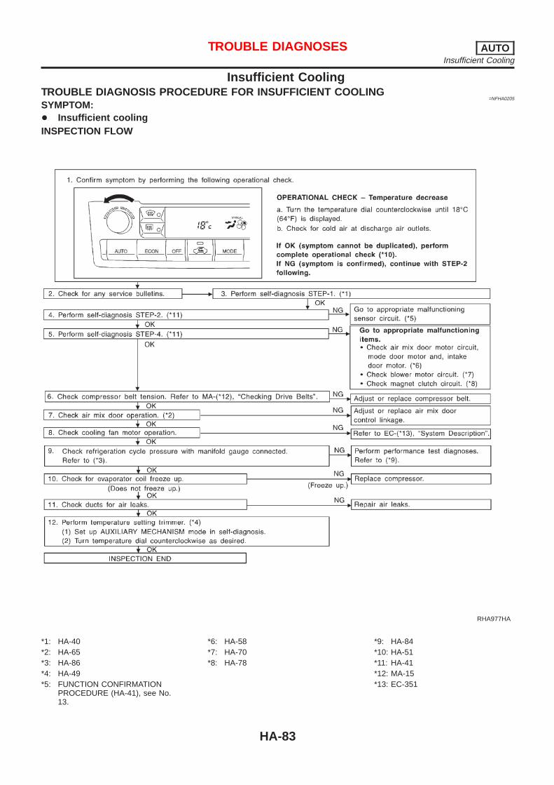
Insufficient CoolingTROUBLE DIAGNOSIS PROCEDURE FOR INSUFFICIENT COOLING
=NFHA0205
SYMPTOM:+ Insufficient coolingINSPECTION FLOW
RHA977HA
*1: HA-40*2: HA-65*3: HA-86*4: HA-49*5: FUNCTION CONFIRMATION
PROCEDURE (HA-41), see No.13.
*6: HA-58*7: HA-70*8: HA-78
*9: HA-84*10: HA-51*11: HA-41*12: MA-15*13: EC-351
TROUBLE DIAGNOSES AUTOInsufficient Cooling
HA-83

PERFORMANCE TEST DIAGNOSESNFHA0206
SHA344F
*1: HA-86*2: HA-86
*3: HA-87 *4: HA-64
TROUBLE DIAGNOSES AUTOInsufficient Cooling (Cont’d)
HA-84

SHA329F
*1: HA-114 *2: HA-69 *3: MA-15
TROUBLE DIAGNOSES AUTOInsufficient Cooling (Cont’d)
HA-85

PERFORMANCE TESTNFHA0207
Test ConditionNFHA0207S01
Testing must be performed as follows:
Vehicle location Indoors or in the shade (in a well-ventilated place)
Doors Closed
Door windows Open
Hood Open
TEMP. Max. COLD
Mode switch (Ventilation) set
REC switch (Recirculation) set
(blower) speed Max. speed set
Engine speed Idle speed
Operate the air conditioning system for 10 minutes before taking measurements.
Test ReadingNFHA0207S02
Recirculating-to-discharge Air Temperature TableNFHA0207S0201
Inside air (Recirculating air) at blower assembly inletDischarge air temperature at center ventilator
°C (°F)Relative humidity%
Air temperature°C (°F)
50 - 60
15 (59) 3.5 - 5.4 (38 - 42)
20 (68) 6.6 - 8.9 (44 - 48)
25 (77) 9.5 - 12.6 (49 - 55)
30 (86) 13.4 - 16.5 (56 - 62)
35 (95) 17.6 - 21.3 (64 - 70)
60 - 70
15 (59) 5.4 - 7.1 (42 - 45)
20 (68) 8.9 - 11.0 (48 - 52)
25 (77) 12.6 - 15.4 (55 - 60)
30 (86) 16.5 - 20.0 (62 - 68)
35 (95) 21.3 - 24.8 (70 - 77)
Ambient Air Temperature-to-operating Pressure TableNFHA0207S0202
Ambient airHigh-pressure (Discharge side)
kPa (bar, kg/cm2, psi)Low-pressure (Suction side)
kPa (bar, kg/cm2, psi)Relative humidity%
Air temperature°C (°F)
50 - 70
15 (59)539 - 657
(5.39 - 6.57, 5.5 - 6.7, 78 - 95)177 - 216
(1.77 - 2.16, 1.8 - 2.2, 26 - 31)
20 (68)677 - 824
(6.77 - 8.24, 6.9 - 8.4, 98 - 119)167 - 206
(1.67 - 2.06, 1.7 - 2.1, 24 - 30)
25 (77)843 - 1,030
(8.43 - 10.30, 8.6 - 10.5, 122 - 149)177 - 226
(1.77 - 2.26, 1.8 - 2.3, 26 - 33)
30 (86)1,030 - 1,275
(10.30 - 12.75, 10.5 - 13.0, 149 - 185)216 - 255
(2.16 - 2.55, 2.2 - 2.6, 31 - 37)
35 (95)1,245 - 1,520
(12.45 - 15.20, 12.7 - 15.5, 181 - 220)265 - 324
(2.65 - 3.24, 2.7 - 3.3, 38 - 47)
TROUBLE DIAGNOSES AUTOInsufficient Cooling (Cont’d)
HA-86

TROUBLE DIAGNOSES FOR ABNORMAL PRESSURENFHA0208
Whenever system’s high and/or low side pressure is abnormal, diagnose using a manifold gauge. The markerabove the gauge scale in the following tables indicates the standard (normal) pressure range. Since the stan-dard (normal) pressure, however, differs from vehicle to vehicle, refer to HA-86 (“Ambient air temperature-to-operating pressure table”).
Both High and Low-pressure Sides are Too High.NFHA0208S01
Gauge indication Refrigerant cycle Probable cause Corrective action
Both high and low-pressure sidesare too high.
AC359A
+ Pressure is reduced soonafter water is splashed oncondenser.
Excessive refrigerant chargein refrigeration cycle
Reduce refrigerant until speci-fied pressure is obtained.
Air suction by cooling fan isinsufficient.
Insufficient condenser coolingperformance
↓1. Condenser fins are
clogged.2. Improper fan rotation of
cooling fan
+ Clean condenser.+ Check and repair cooling
fan as necessary.
+ Low-pressure pipe is notcold.
+ When compressor isstopped high-pressurevalue quickly drops byapproximately 196 kPa(1.96 bar, 2 kg/cm2, 28psi). It then decreasesgradually thereafter.
Poor heat exchange in con-denser(After compressor operationstops, high pressuredecreases too slowly.)
↓Air in refrigeration cycle
Evacuate repeatedly andrecharge system.
Engine tends to overheat. Engine cooling systems mal-function.
Check and repair eachengine cooling system.
+ An area of the low-pres-sure pipe is colder thanareas near the evaporatoroutlet.
+ Plates are sometimes cov-ered with frost.
+ Excessive liquid refrigeranton low-pressure side
+ Excessive refrigerant dis-charge flow
+ Expansion valve is open alittle compared with thespecification.
↓1. Improper thermal valve
installation2. Improper expansion valve
adjustment
Replace expansion valve.
TROUBLE DIAGNOSES AUTOInsufficient Cooling (Cont’d)
HA-87

High-pressure Side is Too High and Low-pressure Side is Too Low.NFHA0208S02
Gauge indication Refrigerant cycle Probable cause Corrective action
High-pressure side is too high andlow-pressure side is too low.
AC360A
Upper side of condenser andhigh-pressure side are hot,however, liquid tank is not sohot.
High-pressure tube or partslocated between compressorand condenser are cloggedor crushed.
+ Check and repair orreplace malfunctioningparts.
+ Check lubricant for con-tamination.
High-pressure Side is Too Low and Low-pressure Side is Too High.NFHA0208S03
Gauge indication Refrigerant cycle Probable cause Corrective action
High-pressure side is too low andlow-pressure side is too high.
AC356A
High and low-pressure sidesbecome equal soon aftercompressor operation stops.
Compressor pressure opera-tion is improper.
↓Damaged inside compressorpackings
Replace compressor.
No temperature differencebetween high and low-pres-sure sides
Compressor pressure opera-tion is improper.
↓Damaged inside compressorpackings.
Replace compressor.
TROUBLE DIAGNOSES AUTOInsufficient Cooling (Cont’d)
HA-88

Both High- and Low-pressure Sides are Too Low.NFHA0208S04
Gauge indication Refrigerant cycle Probable cause Corrective action
Both high- and low-pressure sidesare too low.
AC353A
+ There is a big temperaturedifference betweenreceiver drier outlet andinlet. Outlet temperature isextremely low.
+ Liquid tank inlet andexpansion valve arefrosted.
Compressor dischargecapacity does not change.(Compressor stroke is set atmaximum.)
+ Replace liquid tank ordesiccant assembly.
+ Check lubricant for con-tamination.
+ Temperature of expansionvalve inlet is extremelylow as compared withareas near liquid tank.
+ Expansion valve inlet maybe frosted.
+ Temperature differenceoccurs somewhere inhigh-pressure side
High-pressure pipe locatedbetween receiver drier andexpansion valve is clogged.
+ Check and repair malfunc-tioning parts.
+ Check lubricant for con-tamination.
+ Expansion valve and liquidtank are warm or only coolwhen touched.
Low refrigerant charge↓
Leaking fittings or compo-nents
Check refrigerant for leaks.Refer to “Checking Refriger-ant Leaks”, HA-123.
There is a big temperaturedifference between expan-sion valve inlet and outletwhile the valve itself isfrosted.
Expansion valve closes alittle compared with thespecification.
↓1. Improper expansion valve
adjustment2. Malfunctioning thermal
valve3. Outlet and inlet may be
clogged.
+ Remove foreign particlesby using compressed air.
+ Check lubricant for con-tamination.
An area of the low-pressurepipe is colder than areasnear the evaporator outlet.
Low-pressure pipe is cloggedor crushed.
+ Check and repair malfunc-tioning parts.
+ Check lubricant for con-tamination.
Air flow volume is notenough or is too low.
Evaporator is frozen.↓
Compressor dischargecapacity does not change.(Compressor stroke is set atmaximum length.)
Replace compressor.
TROUBLE DIAGNOSES AUTOInsufficient Cooling (Cont’d)
HA-89

Low-pressure Side Sometimes Becomes Negative.NFHA0208S05
Gauge indication Refrigerant cycle Probable cause Corrective action
Low-pressure side sometimesbecomes negative.
AC354A
+ Air conditioning systemdoes not function anddoes not cyclically coolthe compartment air.
+ The system constantlyfunctions for a certainperiod of time after com-pressor is stopped andrestarted.
Refrigerant does not dis-charge cyclically.
↓Moisture is frozen at expan-sion valve outlet and inlet.
↓Water is mixed with refriger-ant.
+ Drain water from refriger-ant or replace refrigerant.
+ Replace liquid tank ordesiccant assembly.
Low-pressure Side Becomes Negative.NFHA0208S06
Gauge indication Refrigerant cycle Probable cause Corrective action
Low-pressure side becomes nega-tive.
AC362A
Liquid tank or front/rear sideof expansion valve’s pipe isfrosted or dewed.
High-pressure side is closedand refrigerant does not flow.
↓Expansion valve or liquidtank is frosted.
Leave the system at restuntil no frost is present. Startit again to check whether ornot the problem is caused bywater or foreign particles.+ If water is the cause, ini-
tially cooling is okay. Thenthe water freezes causinga blockage. Drain waterfrom refrigerant or replacerefrigerant.
+ If due to foreign particles,remove expansion valveand remove the particleswith dry and compressedair (not shop air).
+ If either of the abovemethods cannot correctthe problem, replaceexpansion valve.
+ Replace liquid tank ordesiccant assembly.
+ Check lubricant for con-tamination.
TROUBLE DIAGNOSES AUTOInsufficient Cooling (Cont’d)
HA-90

Insufficient HeatingTROUBLE DIAGNOSIS PROCEDURE FOR INSUFFICIENT HEATING
=NFHA0209
SYMPTOM:+ Insufficient heatingINSPECTION FLOW
RHA978H
*1: HA-51*2: HA-40*3: HA-41*4: HA-41*5: HA-65
*6: FUNCTION CONFIRMATIONPROCEDURE (HA-41), see No.13.
*7: HA-59*8: HA-71
*9: HA-63*10: LC-16*11: MA-16*12: MA-16*13: LC-11
TROUBLE DIAGNOSES AUTOInsufficient Heating
HA-91

NoiseTROUBLE DIAGNOSIS PROCEDURE FOR NOISE
=NFHA0210
SYMPTOM:+ Noise
SHA331F
*1: HA-114*2: HA-116
*3: HA-111*4: HA-51
*5: MA-15
TROUBLE DIAGNOSES AUTONoise
HA-92

Self-diagnosisTROUBLE DIAGNOSIS PROCEDURE FOR SELF-DIAGNOSIS
=NFHA0211
SYMPTOM:+ Self-diagnosis cannot be performed.INSPECTION FLOW
RHA979H
*1: HA-55*2: HA-95*3: HA-98
*4: HA-102*5: HA-105*6: HA-108
*7: HA-51*8: HA-50*9: HA-51
TROUBLE DIAGNOSES AUTOSelf-diagnosis
HA-93

Memory FunctionTROUBLE DIAGNOSIS PROCEDURE FOR MEMORY FUNCTION
=NFHA0212
SYMPTOM:+ Memory function does not operate.INSPECTION FLOW
RHA980H
*1: HA-55*2: HA-51
*3: HA-41 *4: HA-55
TROUBLE DIAGNOSES AUTOMemory Function
HA-94
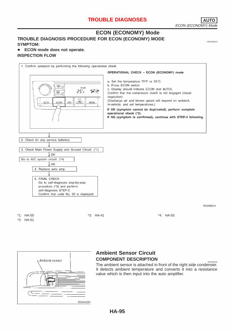
ECON (ECONOMY) ModeTROUBLE DIAGNOSIS PROCEDURE FOR ECON (ECONOMY) MODE
=NFHA0213
SYMPTOM:+ ECON mode does not operate.INSPECTION FLOW
RHA981H
*1: HA-55*2: HA-51
*3: HA-41 *4: HA-55
RHA410H
Ambient Sensor CircuitCOMPONENT DESCRIPTION
NFHA0214
The ambient sensor is attached in front of the right side condenser.It detects ambient temperature and converts it into a resistancevalue which is then input into the auto amplifier.
TROUBLE DIAGNOSES AUTOECON (ECONOMY) Mode
HA-95

AMBIENT TEMPERATURE INPUT PROCESSNFHA0215
The automatic amplifier includes a “processing circuit” for the ambi-ent sensor input. However, when the temperature detected by theambient sensor increases quickly, the processing circuit retards theauto amp. function. It only allows the auto amp. to recognize anambient temperature increase of 0.33°C (0.6°F) per 100 seconds.As an example, consider stopping for a cup of coffee after highspeed driving. Although the actual ambient temperature has notchanged, the temperature detected by the ambient sensor willincrease. This is because the heat from the engine compartmentcan radiate to the front grille area, location of the ambient sensor.
RHA896H
DIAGNOSTIC PROCEDURENFHA0216
SYMPTOM: Ambient sensor circuit is open or shorted. ( or− is indicated on the display as a result of conducting Self-diagnosis STEP 2.)
1 CHECK VOLTAGE BETWEEN AMBIENT SENSOR HARNESS CONNECTOR AND BODY GROUND
Disconnect ambient sensor harness connector.Do approx. 5 volts exist between ambient sensor harness terminal No. 1 and body ground?
RHA052GE
Yes or No
Yes © GO TO 2.
No © GO TO 4.
TROUBLE DIAGNOSES AUTOAmbient Sensor Circuit (Cont’d)
HA-96
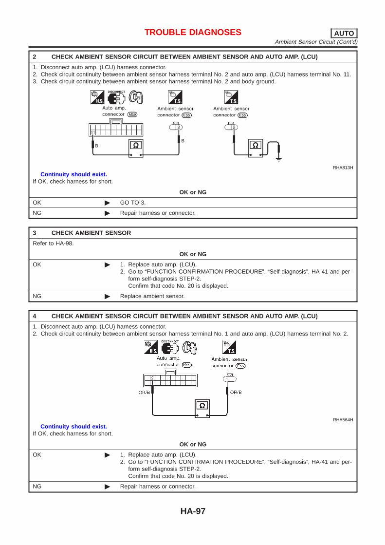
2 CHECK AMBIENT SENSOR CIRCUIT BETWEEN AMBIENT SENSOR AND AUTO AMP. (LCU)
1. Disconnect auto amp. (LCU) harness connector.2. Check circuit continuity between ambient sensor harness terminal No. 2 and auto amp. (LCU) harness terminal No. 11.3. Check circuit continuity between ambient sensor harness terminal No. 2 and body ground.
RHA813H
Continuity should exist.If OK, check harness for short.
OK or NG
OK © GO TO 3.
NG © Repair harness or connector.
3 CHECK AMBIENT SENSOR
Refer to HA-98.
OK or NG
OK © 1. Replace auto amp. (LCU).2. Go to “FUNCTION CONFIRMATION PROCEDURE”, “Self-diagnosis”, HA-41 and per-
form self-diagnosis STEP-2.Confirm that code No. 20 is displayed.
NG © Replace ambient sensor.
4 CHECK AMBIENT SENSOR CIRCUIT BETWEEN AMBIENT SENSOR AND AUTO AMP. (LCU)
1. Disconnect auto amp. (LCU) harness connector.2. Check circuit continuity between ambient sensor harness terminal No. 1 and auto amp. (LCU) harness terminal No. 2.
RHA564H
Continuity should exist.If OK, check harness for short.
OK or NG
OK © 1. Replace auto amp. (LCU).2. Go to “FUNCTION CONFIRMATION PROCEDURE”, “Self-diagnosis”, HA-41 and per-
form self-diagnosis STEP-2.Confirm that code No. 20 is displayed.
NG © Repair harness or connector.
TROUBLE DIAGNOSES AUTOAmbient Sensor Circuit (Cont’d)
HA-97

RHA411H
COMPONENT INSPECTIONNFHA0217
Ambient SensorNFHA0217S01
After disconnecting ambient sensor harness connector, measureresistance between terminals 2 and 1 at sensor harness side, usingthe table below.
Temperature °C (°F) Resistance kΩ
−15 (5) 12.73
−10 (14) 9.92
−5 (23) 7.80
0 (32) 6.19
5 (41) 4.95
10 (50) 3.99
15 (59) 3.24
20 (68) 2.65
25 (77) 2.19
30 (86) 1.81
35 (95) 1.51
40 (104) 1.27
45 (113) 1.07
If NG, replace ambient sensor.
RHA412H
In-vehicle Sensor CircuitCOMPONENT DESCRIPTION
NFHA0218
In-vehicle sensorNFHA0218S01
The in-vehicle sensor is located on instrument lower panel. It con-verts variations in temperature of compartment air drawn from theaspirator into a resistance value. It is then input into the autoamplifier.
TROUBLE DIAGNOSES AUTOAmbient Sensor Circuit (Cont’d)
HA-98

RHA413H
RHA482A
AspiratorNFHA0218S02
The aspirator is located in front of heater unit. It produces vacuumpressure due to air discharged from the heater unit, continuouslytaking compartment air in the aspirator.
RHA897H
DIAGNOSTIC PROCEDURENFHA0219
SYMPTOM: In-vehicle sensor circuit is open or shorted. ( or− is indicated on the display as a result of conducting Self-diagnosis STEP 2.)
1 CHECK IN-VEHICLE SENSOR CIRCUIT BETWEEN IN-VEHICLE SENSOR AND BODY GROUND
Disconnect in-vehicle sensor harness connector.Do approx. 5 volts exist between in-vehicle sensor harness terminal No. 1 and body ground?
SHA318F
Yes or No
Yes © GO TO 2.
No © GO TO 4.
TROUBLE DIAGNOSES AUTOIn-vehicle Sensor Circuit (Cont’d)
HA-99

2 CHECK IN-VEHICLE SENSOR CIRCUIT BETWEEN IN-VEHICLE SENSOR AND AUTO AMP. (LCU)
1. Disconnect auto amp. (LCU) harness connector.2. Check circuit continuity between in-vehicle sensor harness terminal No. 2 and auto amp. (LCU) harness terminal No.
11.3. Check circuit continuity between in-vehicle sensor harness terminal No. 2 and body ground.
RHA814H
Continuity should exist.If OK, check harness for short.
OK or NG
OK © GO TO 3.
NG © Repair harness or connector.
3 CHECK IN-VEHICLE SENSOR
Refer to HA-101.
OK or NG
OK © 1. Replace auto amp.2. Go to “FUNCTION CONFIRMATION PROCEDURE”, “Self-diagnosis”, HA-41 and per-
form self-diagnosis STEP-2.Confirm that code No. 20 is displayed.
NG © 1. Replace in-vehicle sensor.2. Go to “FUNCTION CONFIRMATION PROCEDURE”, “Self-diagnosis”, HA-41 and per-
form self-diagnosis STEP-2.Confirm that code No. 20 is displayed.
TROUBLE DIAGNOSES AUTOIn-vehicle Sensor Circuit (Cont’d)
HA-100

4 CHECK IN-VEHICLE SENSOR CIRCUIT BETWEEN AMBIENT SENSOR AND AUTO AMP. (LCU)
1. Disconnect auto amp. (LCU) harness connector.2. Check circuit continuity between in-vehicle sensor harness terminal No. 1 and auto amp. (LCU) harness terminal No. 3.
RHA479GC
Continuity should exist.If OK, check harness for short.
OK or NG
OK © 1. Replace auto amp. (LCU).2. Go to “FUNCTION CONFIRMATION PROCEDURE”, “Self-diagnosis”, HA-41 and per-
form self-diagnosis STEP-2.Confirm that code No. 20 is displayed.
NG © Repair harness or connector.
RHA414H
COMPONENT INSPECTIONNFHA0220
In-vehicle SensorNFHA0220S01
After disconnecting in-vehicle sensor harness connector, measureresistance between terminals 1 and 2 at sensor harness side, usingthe table below.
TROUBLE DIAGNOSES AUTOIn-vehicle Sensor Circuit (Cont’d)
HA-101

Temperature °C (°F) Resistance kΩ
−15 (5) 12.73
−10 (14) 9.92
−5 (23) 7.80
0 (32) 6.19
5 (41) 4.95
10 (50) 3.99
15 (59) 3.24
20 (68) 2.65
25 (77) 2.19
30 (86) 1.81
35 (95) 1.51
40 (104) 1.27
45 (113) 1.07
If NG, replace in-vehicle sensor.
RHA415H
Sunload Sensor CircuitCOMPONENT DESCRIPTION
NFHA0221
The sunload sensor is located on the right defroster grille. It detectssunload entering through windshield by means of a photo diode.The sensor converts the sunload into a current value which is theninput into the auto amplifier.
SUNLOAD INPUT PROCESSNFHA0222
The auto amp. also includes a processing circuit which “average”the variations in detected sunload over a period of time. This pre-vents drastic swings in the ATC system operation due to small orquick variations in detected sunload.For example, consider driving along a road bordered by an occa-sional group of large trees. The sunload detected by the sunloadsensor will vary whenever the trees obstruct the sunlight. The pro-cessing circuit averages the detected sunload over a period oftime, so that the (insignificant) effect of the trees momentarilyobstructing the sunlight does not cause any change in the ATCsystem operation. On the other hand, shortly after entering a longtunnel, the system will recognize the change in sunload, and thesystem will react accordingly.
TROUBLE DIAGNOSES AUTOIn-vehicle Sensor Circuit (Cont’d)
HA-102

RHA898H
DIAGNOSTIC PROCEDURENFHA0223
SYMPTOM: Sunload sensor circuit is open or shorted. ( or− is indicated on the display as a result of conducting Self-diagnosis STEP 2.)
1 CHECK SUNLOAD SENSOR CIRCUIT BETWEEN SUNLOAD SENSOR AND BODY GROUND
Disconnect sunload sensor harness connector.Do approx. 5 volts exist between sunload sensor harness terminal No. 1 and body ground?
RHA062GD
Yes or No
Yes © GO TO 2.
No © GO TO 4.
2 CHECK SUNLOAD SENSOR CIRCUIT BETWEEN SUNLOAD SENSOR AND AUTO AMP. (LCU)
1. Disconnect auto amp. (LCU) harness connector.2. Check circuit continuity between sunload sensor harness terminal No. 2 and auto amp. (LCU) harness terminal No. 11.3. Check circuit continuity between sunload sensor harness terminal No. 2 and body ground.
RHA815H
Continuity should exist.If OK, check harness for short.
OK or NG
OK © GO TO 3.
NG © Repair harness or connector.
TROUBLE DIAGNOSES AUTOSunload Sensor Circuit (Cont’d)
HA-103

3 CHECK SUNLOAD SENSOR
Refer to HA-105.
OK or NG
OK © 1. Replace auto amp. (LCU).2. Go to “FUNCTION CONFIRMATION PROCEDURE”, “Self-diagnosis”, HA-41 and per-
form self-diagnosis STEP-2.Confirm that code No. 20 is displayed.
NG © 1. Replace sunload sensor.2. Go to “FUNCTION CONFIRMATION PROCEDURE”, “Self-diagnosis”, HA-41 and per-
form self-diagnosis STEP-2.Confirm that code No. 20 is displayed.
4 CHECK SUNLOAD SENSOR CIRCUIT BETWEEN SUNLOAD SENSOR AND AUTO AMP. (LCU)
1. Disconnect auto amp. (LCU) harness connector.2. Check circuit continuity between sunload sensor harness terminal No. 1 and auto amp. (LCU) harness terminal No. 12.
RHA484GC
Continuity should exist.If OK, check harness for short.
OK or NG
OK © 1. Replace auto amp.2. Go to “FUNCTION CONFIRMATION PROCEDURE”, “Self-diagnosis”, HA-41 and per-
form self-diagnosis STEP-2.Confirm that code No. 20 is displayed.
NG © Repair harness or connector.
TROUBLE DIAGNOSES AUTOSunload Sensor Circuit (Cont’d)
HA-104

RHA416H
COMPONENT INSPECTIONNFHA0224
Sunload SensorNFHA0224S01
Measure voltage between auto amp. terminal 12 and body ground.If NG, replace sunload sensor.+ When checking sunload sensor, select a place where sun
shines directly on it.
SHA930E
RHA584E
Intake Sensor CircuitCOMPONENT DESCRIPTION
NFHA0225
Intake SensorNFHA0225S01
The intake sensor is located on the cooling unit. It converts tem-perature of air after it passes through the evaporator into a resis-tance value which is then input to the auto amp.After disconnecting intake sensor harness connector, measureresistance between terminals 1 and 2 at sensor harness side, usingthe table below.
TROUBLE DIAGNOSES AUTOSunload Sensor Circuit (Cont’d)
HA-105

Temperature °C (°F) Resistance kΩ
−15 (5) 12.73
−10 (14) 9.92
−5 (23) 7.80
0 (32) 6.19
5 (41) 4.95
10 (50) 3.99
15 (59) 3.24
20 (68) 2.65
25 (77) 2.19
30 (86) 1.81
35 (95) 1.51
40 (104) 1.27
45 (113) 1.07
If NG, replace intake sensor.
RHA899H
DIAGNOSTIC PROCEDURENFHA0226
SYMPTOM: Intake sensor circuit is open or shorted. ( or− is indicated on the display as a result of conductingSelf-diagnosis STEP 2.)
1 CHECK INTAKE SENSOR CIRCUIT BETWEEN INTAKE SENSOR AND BODY GROUND
Disconnect intake sensor harness connector.Do approx. 5 volts exist between intake sensor harness terminal No. 1 and body ground?
RHA417H
Yes or No
Yes © GO TO 2.
No © GO TO 4.
TROUBLE DIAGNOSES AUTOIntake Sensor Circuit (Cont’d)
HA-106

2 CHECK INTAKE SENSOR CIRCUIT BETWEEN INTAKE SENSOR AND AUTO AMP. (LCU)
1. Disconnect auto amp. (LCU) harness connector.2. Check circuit continuity between intake sensor harness terminal No. 2 and auto amp. (LCU) harness terminal No. 11.3. Check circuit continuity between intake sensor harness terminal No. 2 and body ground.
RHA566HA
Continuity should exist.If OK, check harness for short.
OK or NG
OK © GO TO 3.
NG © Repair harness or connector.
3 CHECK INTAKE SENSOR
Refer to HA-105.
OK or NG
OK © 1. Replace auto amp.2. Go to “FUNCTION CONFIRMATION PROCEDURE”, “Self-diagnosis”, HA-41 and per-
form self-diagnosis STEP-2.Confirm that code No. 20 is displayed.
NG © 1. Replace intake sensor.2. Go to “FUNCTION CONFIRMATION PROCEDURE”, “Self-diagnosis”, HA-41 and per-
form self-diagnosis STEP-2.Confirm that code No. 20 is displayed.
4 CHECK INTAKE SENSOR CIRCUIT BETWEEN AMBIENT SENSOR AND AUTO AMP. (LCU)
1. Disconnect auto amp. (LCU) harness connector.2. Check circuit continuity between intake sensor harness terminal No. 1 and auto amp. (LCU) harness terminal No. 1.
RHA419H
Continuity should exist.If OK, check harness for short.
OK or NG
OK © 1. Replace auto amp.2. Go to “FUNCTION CONFIRMATION PROCEDURE”, “Self-diagnosis”, HA-41 and per-
form self-diagnosis STEP-2.Confirm that code No. 20 is displayed.
NG © Repair harness or connector.
TROUBLE DIAGNOSES AUTOIntake Sensor Circuit (Cont’d)
HA-107

Air Mix Door Motor PBR CircuitDIAGNOSTIC PROCEDURE
NFHA0227
For description of air mix door motor, mode door motor and intakedoor motor circuit, refer to HA-64.SYMPTOM: If PBR circuit is open or shorted. (− or isindicated on the display as a result of conducting Self-diag-nosis STEP 2.)Perform diagnostic procedure for air mix door motor, modedoor motor and intake. Refer to HA-59.
TROUBLE DIAGNOSES AUTOAir Mix Door Motor PBR Circuit
HA-108

HFC-134a (R-134a) Service ProcedureNFHA0228
SETTING OF SERVICE TOOLS AND EQUIPMENTNFHA0228S01
Discharging RefrigerantNFHA0228S0101
WARNING:Avoid breathing A/C refrigerant and lubricant vapor or mist. Exposure may irritate eyes, nose andthroat. Use only approved recovery/recycling equipment to discharge HFC-134a (R-134a) refrigerant.If accidental system discharge occurs, ventilate work area before resuming service. Additional healthand safety information may be obtained from refrigerant and lubricant manufacturers.
SHA539DE
Evacuating System and Charging RefrigerantNFHA0228S0102
SHA540DC
SERVICE PROCEDURE AUTOHFC-134a (R-134a) Service Procedure
HA-109

SHA383F
*1: HA-111*2: HA-123
*3: HA-124 *4: HA-84
SERVICE PROCEDURE AUTOHFC-134a (R-134a) Service Procedure (Cont’d)
HA-110

Maintenance of Lubricant Quantity inCompressor
NFHA0229
The lubricant in the compressor circulates through the system withthe refrigerant. Add lubricant to compressor when replacing anycomponent or after a large gas leakage occurred. It is important tomaintain the specified amount. If lubricant quantity is not main-tained properly, the following malfunctions may result:+ Lack of lubricant: May lead to a seized compressor+ Excessive lubricant: Inadequate cooling (thermal exchange
interference)
LUBRICANTNFHA0229S01
Name: Nissan A/C System Oil Type SPart number: KLH00-PAGS0
CHECKING AND ADJUSTINGNFHA0229S02
Adjust the lubricant quantity according to the test group shownbelow.
1 CHECK LUBRICANT RETURN OPERATION
Can lubricant return operation be performed?+ A/C system works properly.+ There is no evidence of a large amount of lubricant leakage.
Yes or No
Yes © GO TO 2.
No © GO TO 3.
2 PERFORM LUBRICANT RETURN OPERATION, PROCEEDING AS FOLLOWS:
1. Start engine, and set the following conditions:Test conditionEngine speed: Idling to 1,200 rpmA/C or AUTO switch: ONBlower speed: Max. positionTemp. control: Optional [Set so that intake air temperature is 25 to 30°C (77 to 86°F).]
2. Next item is for V-6 compressor. Connect the manifold gauge, and check that the high pressure side pressureis 588 kPa (5.9 bar, 6 kg/cm 2, 85 psi) or higher.If less than the reference level, attach a cover to the front face of the condenser to raise the pressure.
3. Perform lubricant return operation for about 10 minutes.4. Stop engine.CAUTION:If excessive lubricant leakage is noted, do not perform the lubricant return operation.
OK © GO TO 3.
3 CHECK COMPRESSOR
Should the compressor be replaced?
Yes or No
Yes © Go to “Lubricant Adjustment Procedure for Compressor Replacement”, (HA-112).
No © GO TO 4.
SERVICE PROCEDURE AUTOMaintenance of Lubricant Quantity in Compressor
HA-111

4 CHECK ANY PART
Is there any part to be replaced? (Evaporator, condenser, liquid tank or in case there is evidence of a large amount oflubricant leakage.)
Yes or No
Yes © Go to “Lubricant Adjusting Procedure for Components Replacement ExceptCompressor”, (HA-112).
No © Carry out the A/C performance test.
Lubricant Adjusting Procedure for ComponentsReplacement Except Compressor
NFHA0229S0201
After replacing any of the following major components, add thecorrect amount of lubricant to the system.Amount of lubricant to be added
Part replaced
Lubricant to be added tosystem
RemarksAmount of lubricant
m! (Imp fl oz)
Evaporator 75 (2.6) —
Condenser 75 (2.6) —
Liquid tank 5 (0.2)Add if compressor is not
replaced. *1
In case of refrigerantleak
30 (1.1) Large leak
— Small leak *2
*1: If compressor is replaced, addition of lubricant is included in the table.*2: If refrigerant leak is small, no addition of lubricant is needed.
Lubricant Adjusting Procedure for CompressorReplacement
NFHA0229S0202
1. Discharge refrigerant into the refrigerant recovery/recyclingequipment. Measure lubricant discharged into the recovery/recycling equipment.
2. Remove the drain plug of the “old” (removed) compressor.Drain the lubricant into a graduated container and record theamount of drained lubricant.
3. Remove the drain plug and drain the lubricant from the “new”compressor into a separate, clean container.
4. Measure an amount of new lubricant installed equal to amountdrained from “old” compressor. Add this lubricant to “new” com-pressor through the suction port opening.
5. Measure an amount of new lubricant equal to the amountrecovered during discharging. Add this lubricant to “new” com-pressor through the suction port opening.
6. Torque the drain plug.18 - 19 N·m (1.8 - 1.9 kg-m, 13 - 14 ft-lb)
7. If the liquid tank also needs to be replaced, add an additional5 m! (0.2 Imp fl oz) of lubricant at this time.Do not add this 5 m! (0.2 Imp fl oz) of lubricant if only replac-ing the compressor.
SERVICE PROCEDURE AUTOMaintenance of Lubricant Quantity in Compressor (Cont’d)
HA-112

RHA065DI
SERVICE PROCEDURE AUTOMaintenance of Lubricant Quantity in Compressor (Cont’d)
HA-113

CompressorREMOVAL AND INSTALLATION
NFHA0230
RHA463E
Compressor ClutchOVERHAUL
NFHA0231
RHA122F
SERVICE PROCEDURE AUTOCompressor
HA-114

RHA136E
REMOVALNFHA0232
+ When removing center bolt, hold clutch disc with clutch discwrench.
RHA399FA
RHA124FA
+ Remove the clutch disc using the clutch disc puller.Insert the holder’s three pins into the holes in the clutch disc.Rotate the holder clockwise to hook it onto the plate. Then,tighten the center bolt to remove the clutch disc.After removing the clutch disc, remove the shims from eitherthe drive shaft or the clutch disc.
RHA138E
+ Remove the snap ring using external snap ring pliers.
RHA139E
+ Pulley removalPosition the center pulley puller on the end of the drive shaft,and remove the pulley assembly using any commercially avail-able pulley puller.To prevent the pulley groove from being deformed, thepuller claws should be positioned onto the edge of thepulley assembly.
SERVICE PROCEDURE AUTOCompressor Clutch (Cont’d)
HA-115
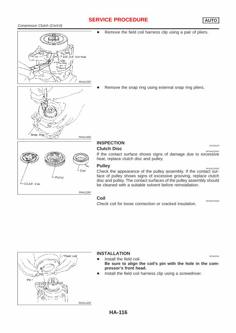
RHA125F
+ Remove the field coil harness clip using a pair of pliers.
RHA145E
+ Remove the snap ring using external snap ring pliers.
RHA126F
INSPECTIONNFHA0233
Clutch DiscNFHA0233S01
If the contact surface shows signs of damage due to excessiveheat, replace clutch disc and pulley.
PulleyNFHA0233S02
Check the appearance of the pulley assembly. If the contact sur-face of pulley shows signs of excessive grooving, replace clutchdisc and pulley. The contact surfaces of the pulley assembly shouldbe cleaned with a suitable solvent before reinstallation.
CoilNFHA0233S03
Check coil for loose connection or cracked insulation.
RHA142E
INSTALLATIONNFHA0234
+ Install the field coil.Be sure to align the coil’s pin with the hole in the com-pressor’s front head.
+ Install the field coil harness clip using a screwdriver.
SERVICE PROCEDURE AUTOCompressor Clutch (Cont’d)
HA-116

RHA143E
+ Install the pulley assembly using the installer and a handpress, and then install the snap ring using snap ring pliers.
RHA127F
+ Install the clutch disc on the drive shaft, together with theoriginal shim(s). Press the clutch disc down by hand.
RHA086E
+ Using the holder to prevent clutch disc rotation, tighten the boltto 14 N·m (1.4 kg-m, 10 ft-lb) torque.After tightening the bolt, check that the pulley rotatessmoothly.
RHA087E
+ Check clearance around the entire periphery of clutch disc.Disc-to-pulley clearance:
0.3 - 0.6 mm (0.012 - 0.024 in)If the specified clearance is not obtained, replace adjustingspacer and readjust.
Break-in OperationNFHA0234S01
When replacing compressor clutch assembly, always carry out thebreak-in operation. This is done by engaging and disengaging theclutch about thirty times. Break-in operation raises the level oftransmitted torque.
SERVICE PROCEDURE AUTOCompressor Clutch (Cont’d)
HA-117

Heater Unit (Heater Core)REMOVAL
NFHA0249
RHA567H
1. Drain the cooling system. Refer to MA-16, “Changing EngineCoolant”.
2. Discharge the A/C system. Refer to HA-109.3. Disconnect the two heater hoses from inside the engine com-
partment.4. Remove the Blower and cooling unit. Refer to HA-119.5. Remove the steering member assembly. Refer to BT-20,
“Removal and Installation”.6. Remove the heater unit.7. Remove the heater core.
INSTALLATIONNFHA0250
Installation is basically the reverse order of removal.When filling radiator with coolant, refer to MA-16, “ChangingEngine Coolant”.Recharge the A/C system. Refer to HA-109.
SERVICE PROCEDURE AUTOHeater Unit (Heater Core)
HA-118

Blower and Cooling Unit (A/C Evaporator)REMOVAL
NFHA0251
RHA422HA
RHA421H
1. Discharge the A/C system. Refer to HA-109.2. Disconnect the two refrigerant lines from the engine compart-
ment.Cap the A/C lines to prevent moisture from entering the sys-tem.
3. Remove the glove box and mating trim. Refer to BT-20,“Removal and Installation”.
4. Disconnect the thermal amp. connector.5. Disconnect the intake sensor connector.6. Disconnect the fan control amp. and blower motor connector.7. Remove the blower and cooling unit.8. Separate the blower and cooling unit case, and remove the
evaporator.9. Remove the three bolts and then remove the motor from the
blower case.
INSTALLATIONNFHA0252
Installation is basically the reverse order of removal.Recharge the A/C system. Refer to HA-109.
SERVICE PROCEDURE AUTOBlower and Cooling Unit (A/C Evaporator)
HA-119

RHA984HA
Desiccant AssemblyREMOVAL
NFHA0273
1. Discharge the A/C system. Refer to HA-109.2. Disconnect the two refrigerant lines from condenser. Cap the
A/C lines to prevent moisture from entering the system.3. Remove the radiator top mount.4. Remove the condenser assembly.5. Remove the snap ring, cap, O-ring, filter and desiccant
assembly.
INSTALLATIONNFHA0274
Install in reverse order of removal.Recharge the A/C system. Refer to HA-109.CAUTION:Always replace used snap ring, cap, O-ring, filter and desic-cant assembly.
SERVICE PROCEDURE AUTODesiccant Assembly
HA-120

Refrigerant LinesREMOVAL AND INSTALLATION
=NFHA0235
+ Refer to page HA-5 regarding “Precautions for Refrigerant Connection”.
RHA982H
SERVICE PROCEDURE AUTORefrigerant Lines
HA-121

RHA983H
+ Refer to page HA-5 regarding “Precautions for Refrigerant Connection”.
SERVICE PROCEDURE AUTORefrigerant Lines (Cont’d)
HA-122

CHECKING REFRIGERANT LEAKSNFHA0236
Preliminary Check=NFHA0236S01
+ Perform a visual inspection of all refrigeration parts, fittings,hoses, and components for signs of A/C lubricant leakage,damage and corrosion. Take note of the areas with A/C lubri-cant leakage to allow extra time in these areas with electronicleak detector.
+ If dye is observed, confirm the leak with an electronic refriger-ant leak detector. It is possible a prior leak was repaired andnot properly cleaned.
+ When searching for leaks, do not stop when one leak is foundbut continue to check for additional leaks at all system compo-nents and connections.
+ When searching for refrigerant leaks using an electronic leakdetector, move the probe along the suspected leak area at 1to 2 inches per second and no further than 1/4 inch from thecomponent.
NOTE:Moving the electronic leak detector probe slower and closer tothe suspected leak area will improve the chances of finding aleak.
SHA705EB
Precautions for Handling Leak DetectorNFHA0236S02
When performing a refrigerant leak check, use an A/C leak detec-tor or equivalent. Ensure that the instrument is calibrated and setproperly per the operating instructions.The leak detector is a delicate device. In order to use the leakdetector properly, read the operating instructions and perform anyspecified maintenance.Other gases in the work area or substances on the A/Ccomponents, for example, anti-freeze, windshield washerfluid, solvents and lubricants, may falsely trigger the leakdetector. Make sure the surfaces to be checked are clean.Clean with a dry cloth or blow off with shop air. Do not allowthe sensor tip of the detector to contact with any substance.This can also cause false readings and may damage the detec-tor.
SHA707EA
1. Position probe approximately 5 mm (3/16 in) away from pointto be checked.
SERVICE PROCEDURE AUTORefrigerant Lines (Cont’d)
HA-123

SHA706E
2. When testing, circle each fitting completely with probe.
SHA708EA
3. Move probe along component approximately 25 to 50 mm (1to 2 in)/sec.
Checking ProcedureNFHA0236S03
To prevent inaccurate or false readings, make sure there is norefrigerant vapor, shop chemicals, or cigarette smoke in thevicinity of the vehicle. Perform the leak test in calm area (lowair/wind movement) so that the leaking refrigerant is not dis-persed.1. Turn engine off.2. Connect a suitable A/C manifold gauge set to the A/C service
ports.3. Check if the A/C refrigerant pressure is at least 345 kPa (3.45
bar, 3.52 kg/cm2, 50 psi) above 16°C (61°F). If less thanspecification, recover/evacuate and recharge the system withthe specified amount of refrigerant.
NOTE:At temperatures below 16°C (61°F), leaks may not be detectedsince the system may not reach 345 kPa (3.45 bar, 3.52 kg/cm2,50 psi).4. Conduct the leak test from the high side (compressor dis-
charge a to evaporator inlet e) to the low side (evaporator dis-charge e to shaft seal j). Refer to HA-121. Perform a leakcheck for the following areas carefully. Clean the componentto be checked and move the leak detector probe completelyaround the connection/component.
+ CompressorCheck the fitting of high and low pressure hoses, relief valveand shaft seal.
+ Liquid tankCheck the refrigerant pressure sensor, tube fitting, weld seamsand the fusible plug mount.
+ Service valvesCheck all around the service valves. Ensure service valve capsare secured on the service valves (to prevent leaks).
SERVICE PROCEDURE AUTORefrigerant Lines (Cont’d)
HA-124

NOTE:After removing A/C manifold gauge set from service valves, wipeany residue from valves to prevent any false readings by leakdetector.+ Cooling unit (Evaporator)
With engine OFF, turn blower fan on “High” for at least 15seconds to dissipate any refrigerant trace in the cooling unit.Wait a minimum of 10 minutes accumulation time (refer to themanufacturer’s recommended procedure for actual wait time)before inserting the leak detector probe into the drain hose.Keep the probe inserted for at least ten seconds. Use cautionnot to contaminate the ptobe tip with water or dirt that may bein the drain hose.
5. If a leak detector detects a leak, verify at least once by blow-ing compressed air into area of suspected leak, then repeatcheck as outlined above.
6. Do not stop when one leak is found. Continue to check foradditional leaks at all system components.If no leaks are found, perform steps 7 - 10.
7. Start engine.8. Set the heater A/C control as follows:1) A/C or AUTO switch ON.2) Face mode3) Recirculation switch ON4) Max cold temperature5) Fan speed high9. Run engine at 1,500 rpm for at least 2 minutes.10. Turn engine off and perform leak check again following steps
4 through 6 above.
SHA839E
Refrigerant leaks should be checked immediately afterstopping the engine. Begin with the leak detector at thecompressor. The pressure on the high pressure side willgradually drop after refrigerant circulation stops and pres-sure on the low pressure side will gradually rise, as shownin the graph. Some leaks are more easily detected whenpressure is high.
11. Discharge A/C system using approved refrigerant recoveryequipment. Repair the leaking fitting or component as neces-sary.
12. Evacuate and recharge A/C system and perform the leak testto confirm no refrigerant leaks.
13. Conduct A/C performance test to ensure system worksproperly.
SERVICE PROCEDURE AUTORefrigerant Lines (Cont’d)
HA-125

Fluorescent Dye Leak DetectorNFHA0275
PRECAUTIONS FOR FLUORESCENT DYE LEAKDETECTION
NFHA0275S01
+ The fluorescent dye leak detector is not a replacement for anelectronic refrigerant leak detector. The fluorescent dye leakdetector should be used in conjunction with an electronicrefrigerant leak detector to pinpoint refrigerant leaks.
+ For your safety and your customer’s satisfaction, read and fol-low all manufacturer’s operating instructions and precautionsprior to performing the work.
+ Refer to “Precautions for Leak Detection Dye”, HA-4.
CHECKING SYSTEM FOR LEAKS USING THEFLUORESCENT LEAK DETECTOR
NFHA0275S02
1. Check A/C system for leaks using the UV lamp and safetyglasses (J-42220) in a low sunlight area (area without windowspreferable). Illuminate all components, fittings and lines. Thedye will appear as a bright green/yellow area at the point ofleakage. Fluorescent dye observed at the evaporator drainopening indicates an evaporator core assembly (tubes, core orTXV) leak.
2. If the suspected area is difficult to see, use an adjustable mir-ror or wipe the area with a clean shop rag or cloth, then checkthe cloth with the UV lamp for dye residue.
3. Confirm any suspected leaks with an approved electronicrefrigerant leak detector.
4. After the leak is repaired, remove any residual dye using dyecleaner (J-43872) to prevent future misdiagnosis.
5. Perform a system performance check and verify the leak repairwith an approved electronic refrigerant leak detector.
DYE INJECTIONNFHA0275S03
(This procedure is only necessary when re-charging the system orwhen the compressor has seized and was replaced.)Refer to “Precautions for Leak Detection Dye”, HA-4.1. Check A/C system static (at rest) pressure. Pressure must be
at least 345 kPa (3.45 bar, 3.52 kg/cm2, 50 psi).2. Pour one bottle (1/4 ounce / 7.4 cc) of the A/C refrigerant dye
into the injector (J-41459).3. Connect the injector tool to the A/C LOW PRESSURE side
service fitting.4. Start engine and switch A/C ON.5. With the A/C operating (compressor running), inject one bottle
(1/4 ounce / 7.4 cc) of fluorescent dye through the low-pres-sure service valve using dye injector (J-41459) (refer to themanufacturer’s operating instructions).
6. With the engine still running, disconnect the injector tool fromthe service fitting.
CAUTION:Be careful not to allow dye to spray or drip when disconnect-ing the injector from the system.NOTE:If repairing the A/C system or replacing a component, pour thedye directly into the open system connection and proceedwith the service procedures.7. Operate the A/C system for a minimum of 20 minutes to mix
SERVICE PROCEDURE AUTOFluorescent Dye Leak Detector
HA-126

the dye with the system oil. Depending on the leak size, oper-ating conditions and location of the leak, it may take from min-utes to days for the dye to penetrate a leak and become visible.
BeltTENSION ADJUSTMENT
NFHA0237
+ Refer to MA-15, “Checking Drive Belt”.
Idle Air Control Valve (IACV) — Auxiliary AirControl (AAC) ValveINSPECTION
NFHA0238
+ Refer to EC-324, and HA-20, “Description”.
RHA042G
Ventilation Air FilterFUNCTION
NFHA0266
Air inside passenger compartment is kept clean at either recircula-tion or fresh mode by installing ventilation air filter into cooling unit.NOTE:To replace ventilation air filter, refer to “PERIODICMAINTENANCE”, MA-8, MA-11.Caution label is fixed inside the glove box.
SHA381F
REPLACEMENT PROCEDURENFHA0267
1. Remove glove box.2. Remove instrument lower panel from instrument panel.3. Remove filter cover fixed clip.4. Slide the filter cover to the upper side and then remove it.5. Take out the lower side ventilation air filter from cooling unit.6. Then slide upper side filter to the bottom position and take off
the ventilation air filter from the cooling unit.7. Replace with new one and reinstall on cooling unit.
SERVICE PROCEDURE AUTOBelt
HA-127

8. Reinstall filter cover, clip, instrument lower panel and glovebox.
SERVICE PROCEDURE AUTOVentilation Air Filter (Cont’d)
HA-128

AutoCOMPRESSOR
NFHA0241
Model CALSONIC make V-6
Type V-6 variable displacement
Displacementcm3 (cu in)/rev.
Max. 184 (11.228)
Min. 14.5 (0.885)
Cylinder bore x strokemm (in)
37 (1.46) x [2.3 - 28.6 (0.091 - 1.126)]
Direction of rotation Clockwise (viewed from drive end)
Drive belt Poly V
LUBRICANTNFHA0242
Model CALSONIC make V-6
Name Nissan A/C System Oil Type S
Part number* KLH00-PAGS0
Capacitym! (Imp fl oz)
Total in system 200 (7.0) [180 (6.3)]
Compressor (Service part) chargingamount
200 (7.0) [180 (6.3)]
*: Always check with the Parts Department for the latest parts information.[ ]: Capacity will be changed as a design change.
REFRIGERANTNFHA0243
Type HFC-134a (R-134a)
Capacitykg (lb)
0.60 - 0.70 (1.32 - 1.54)
ENGINE IDLING SPEED (WHEN A/C IS ON)NFHA0244
+ Refer to EC-559, “Description”.
BELT TENSIONNFHA0245
+ Refer to MA-15, “Checking Drive Belts”.
SERVICE DATA AND SPECIFICATIONS (SDS) AUTOAuto
HA-129

Supplemental Restraint System (SRS) “AIRBAG” and “SEAT BELT PRE-TENSIONER”
NFHA0060
The Supplemental Restraint System such as “AIR BAG” and “SEAT BELT PRE-TENSIONER” used along witha seat belt, helps to reduce the risk or severity of injury to the driver and front passenger for certain types ofcollision. The SRS system composition which is available to NISSAN MODEL A33 is as follows (The compo-sition varies according to optional equipment.):+ For a frontal collision
The Supplemental Restraint System consists of driver air bag module (located in the center of the steer-ing wheel), front passenger air bag module (located on the instrument panel on passenger side), seat beltpre-tensioners, a diagnosis sensor unit, warning lamp, wiring harness and spiral cable.
+ For a side collisionThe Supplemental Restraint System consists of front side air bag module (located in the outer side of frontseat), satellite sensor, diagnosis sensor unit (one of components of air bags for a frontal collision), wiringharness, warning lamp (one of components of air bags for a frontal collision).
Information necessary to service the system safely is included in the RS section of this Service Manual.WARNING:+ To avoid rendering the SRS inoperative, which could increase the risk of personal injury or death
in the event of a collision which would result in air bag inflation, all maintenance should be per-formed by an authorized NISSAN dealer.
+ Improper maintenance, including incorrect removal and installation of the SRS, can lead to per-sonal injury caused by unintentional activation of the system. For removal of Spiral Cable and AirBag Module, see the RS section.
+ Do not use electrical test equipment on any circuit related to the SRS unless instructed to in thisService Manual. Spiral cable and wiring harnesses covered with yellow insulation or tape either justbefore the harness connectors or for the complete harness are related to the SRS.
Precautions for Working with HFC-134a(R-134a)
NFHA0061
WARNING:+ CFC-12 (R-12) refrigerant and HFC-134a (R-134a) refrigerant are not compatible. These refrigerants
must never be mixed, even in the smallest amounts. If the refrigerants are mixed and compressorfailure is likely to occur.
+ Use only specified lubricant for the HFC-134a (R-134a) A/C system and HFC-134a (R-134a) compo-nents. If lubricant other than that specified is used, compressor failure is likely to occur.
+ The specified HFC-134a (R-134a) lubricant rapidly absorbs moisture from the atmosphere. The fol-lowing handling precautions must be observed:
a) When removing refrigerant components from a vehicle, immediately cap (seal) the component tominimize the entry of moisture from the atmosphere.
b) When installing refrigerant components to a vehicle, do not remove the caps (unseal) until justbefore connecting the components. Connect all refrigerant loop components as quickly as pos-sible to minimize the entry of moisture into system.
c) Only use the specified lubricant from a sealed container. Immediately reseal containers of lubri-cant. Without proper sealing, lubricant will become moisture saturated and should not be used.
d) Avoid breathing A/C refrigerant and lubricant vapor or mist. Exposure may irritate eyes, noseand throat. Use only approved recovery/recycling equipment to discharge HFC-134a (R-134a)refrigerant. If accidental system discharge occurs, ventilate work area before resuming service.Additional health and safety information may be obtained from refrigerant and lubricant manu-facturers.
e) Do not allow lubricant (Nissan A/C System Oil Type S) to come in contact with styrofoam parts.Damage may result.
PRECAUTIONS MANUALSupplemental Restraint System (SRS) “AIR BAG” and “SEAT BELT PRE-TENSIONER”
HA-130

General Refrigerant Precautions=NFHA0062
WARNING:+ Do not release refrigerant into the air. Use approved recovery/recycling equipment to capture the
refrigerant every time an air conditioning system is discharged.+ Always wear eye and hand protection (goggles and gloves) when working with any refrigerant or
air conditioning system.+ Do not store or heat refrigerant containers above 52°C (125°F).+ Do not heat a refrigerant container with an open flame; if container warming is required, place the
bottom of the container in a warm pail of water.+ Do not intentionally drop, puncture, or incinerate refrigerant containers.+ Keep refrigerant away from open flames: poisonous gas will be produced if refrigerant burns.+ Refrigerant will displace oxygen, therefore be certain to work in well ventilated areas to prevent
suffocation.+ Do not pressure test or leak test HFC-134a (R-134a) service equipment and/or vehicle air condi-
tioning systems with compressed air during repair. Some mixtures of air and R-134a have beenshown to be combustible at elevated pressures. These mixtures, if ignited, may cause injury orproperty damage. Additional health and safety information may be obtained from refrigerant manu-facturers.
Precautions for Leak Detection DyeNFHA0276
+ The A/C system contains a fluorescent leak detection dye used for locating refrigerant leaks. An ultravio-let (UV) lamp is required to illuminate the dye when inspecting for leaks.
+ Always wear fluorescence enhancing UV safety glasses to protect your eyes and enhance the visibility ofthe fluorescent dye.
+ A compressor shaft seal should not be repaired because of dye seepage. The compressor shaft sealshould only be repaired after confirming the leak with an electronic refrigerant leak detector.
+ Always remove any dye from the leak area after repairs are complete to avoid a misdiagnosis during afuture service.
+ Do not allow dye to come into contact with painted body panels or interior components. If dye is spilled,clean immediately with the approved dye cleaner. Fluorescent dye left on a surface for an extended periodof time cannot be removed.
+ Do not spray the fluorescent dye cleaning agent on hot surfaces (engine exhaust manifold, etc.).+ Do not use more than one refrigerant dye bottle (1/4 ounce / 7.4 cc) per A/C system.+ Leak detection dyes for R-134a and R12 A/C systems are different. Do not use R-134a leak detection dye
in R-12 A/C system or R-12 leak detection dye in R-134a A/C systems or A/C system damage may result.+ The fluorescent properties of the dye will remain for over three (3) years unless a compressor failure
occurs.
SHA436FA
Precaution for Identification Label on VehicleNFHA0277
+ Vehicles with factory installed fluorescent dye have this iden-tification label on the under side of hood.
+ Vehicles with factory installed fluorescent dye have a greenlabel.
+ Vehicles without factory installed fluorescent dye have a bluelabel.
PRECAUTIONS MANUALGeneral Refrigerant Precautions
HA-131

Precautions for Refrigerant ConnectionNFHA0063
A new type refrigerant connection has been introduced to all refrigerant lines except the following portion.+ Expansion valve to cooling unit
FEATURES OF NEW TYPE REFRIGERANT CONNECTIONNFHA0063S01
+ The O-ring has been relocated. It has also been provided with a groove for proper installation. This elimi-nates the chance of the O-ring being caught in, or damaged by, the mating part. The sealing direction ofthe O-ring is now set vertically in relation to the contacting surface of the mating part to improve sealingcharacteristics.
+ The reaction force of the O-ring will not occur in the direction that causes the joint to pull out, therebyfacilitating piping connections.
SHA815E
PRECAUTIONS MANUALPrecautions for Refrigerant Connection
HA-132

O-RING AND REFRIGERANT CONNECTIONNFHA0063S02
RHA960HA
CAUTION:The new and former refrigerant connections use different O-ring configurations. Do not confuseO-rings since they are not interchangeable. If a wrong O-ring is installed, refrigerant will leak at, oraround, the connection.
PRECAUTIONS MANUALPrecautions for Refrigerant Connection (Cont’d)
HA-133

O-Ring Part Numbers and SpecificationsNFHA0063S0201
SHA814E
Connectiontype
O-ringsize
Part number D mm (in) W mm (in)
New8
92471 N8210 6.8 (0.268) 1.85 (0.0728)
Former 92470 N8200 6.07 (0.2390) 1.78 (0.0701)
New12
92472 N8210 10.9 (0.429) 2.43 (0.0957)
Former 92475 71L00 11.0 (0.433) 2.40 (0.0945)
New16
92473 N8210 13.6 (0.535) 2.43 (0.0957)
Former 92475 72L00 14.3 (0.563) 2.30 (0.0906)
New19
92474 N8210 16.5 (0.650) 2.43 (0.0957)
Former 92477 N8200 17.12 (0.6740) 1.78 (0.0701)
WARNING:Make sure all refrigerant is discharged into the recycling equipment and the pressure in the systemis less than atmospheric pressure. Then gradually loosen the discharge side hose fitting and removeit.CAUTION:When replacing or cleaning refrigerant cycle components, observe the following.+ When the compressor is removed, store it in the same position as it is when mounted on the car.
Failure to do so will cause lubricant to enter the low pressure chamber.+ When connecting tubes, always use a torque wrench and a back-up wrench.+ After disconnecting tubes, immediately plug all openings to prevent entry of dirt and moisture.+ When installing an air conditioner in the vehicle, connect the pipes as the final stage of the opera-
tion. Do not remove the seal caps of pipes and other components until just before required forconnection.
+ Allow components stored in cool areas to warm to working area temperature before removing sealcaps. This prevents condensation from forming inside A/C components.
+ Thoroughly remove moisture from the refrigeration system before charging the refrigerant.+ Always replace used O-rings.+ When connecting tube, apply lubricant to circle of the O-rings shown in illustration. Be careful not
to apply lubricant to threaded portion.Lubricant name: Nissan A/C System Oil Type SPart number: KLH00-PAGS0
+ O-ring must be closely attached to dented portion of tube.+ When replacing the O-ring, be careful not to damage O-ring and tube.+ Connect tube until you hear it click, then tighten the nut or bolt by hand until snug. Make sure that
the O-ring is installed to tube correctly.+ After connecting line, conduct leak test and make sure that there is no leakage from connections.
When the gas leaking point is found, disconnect that line and replace the O-ring. Then tightenconnections of seal seat to the specified torque.
PRECAUTIONS MANUALPrecautions for Refrigerant Connection (Cont’d)
HA-134

RHA861F
Precautions for Servicing CompressorNFHA0064
+ Plug all openings to prevent moisture and foreign matter from entering.+ When the compressor is removed, store it in the same position as it is when mounted on the car.+ When replacing or repairing compressor, follow “Maintenance of Lubricant Quantity in Compres-
sor” exactly. Refer to HA-202.+ Keep friction surfaces between clutch and pulley clean. If the surface is contaminated, with
lubricant, wipe it off by using a clean waste cloth moistened with thinner.+ After compressor service operation, turn the compressor shaft by hand more than five turns in
both directions. This will equally distribute lubricant inside the compressor. After the compressoris installed, let the engine idle and operate the compressor for one hour.
+ After replacing the compressor magnet clutch, apply voltage to the new one and check for normaloperation.
Precautions for Service EquipmentNFHA0065
RECOVERY/RECYCLING EQUIPMENTNFHA0065S01
Follow the manufacturer’s instructions for machine operation andmachine maintenance. Never introduce any refrigerant other thanthat specified into the machine.
ELECTRONIC LEAK DETECTORNFHA0065S02
Follow the manufacture’s instructions for tester operation andtester maintenance.
PRECAUTIONS MANUALPrecautions for Servicing Compressor
HA-135

RHA270D
VACUUM PUMPNFHA0065S03
The lubricant contained inside the vacuum pump is not compatiblewith the specified lubricant for HFC-134a (R-134a) A/C systems.The vent side of the vacuum pump is exposed to atmosphericpressure. So the vacuum pump lubricant may migrate out of thepump into the service hose. This is possible when the pump isswitched off after evacuation (vacuuming) and hose is connectedto it.To prevent this migration, use a manual valve situated near thehose-to-pump connection, as follows.+ Usually vacuum pumps have a manual isolator valve as part
of the pump. Close this valve to isolate the service hose fromthe pump.
+ For pumps without an isolator, use a hose equipped with amanual shut-off valve near the pump end. Close the valve toisolate the hose from the pump.
+ If the hose has an automatic shut off valve, disconnect thehose from the pump: as long as the hose is connected, thevalve is open and lubricating oil may migrate.
Some one-way valves open when vacuum is applied and closeunder a no vacuum condition. Such valves may restrict the pump’sability to pull a deep vacuum and are not recommended.
SHA533D
MANIFOLD GAUGE SETNFHA0065S04
Be certain that the gauge face indicates R-134a or 134a. Makesure the gauge set has 1/2″-16 ACME threaded connections forservice hoses. Confirm the set has been used only with refrigerantHFC-134a (R-134a) along with specified lubricant.
RHA272D
SERVICE HOSESNFHA0065S05
Be certain that the service hoses display the markings described(colored hose with black stripe). All hoses must include positiveshut off devices (either manual or automatic) near the end of thehoses opposite the manifold gauge.
RHA273D
SERVICE COUPLERSNFHA0065S06
Never attempt to connect HFC-134a (R-134a) service couplers toan CFC-12 (R-12) A/C system. The HFC-134a (R-134a) couplerswill not properly connect to the CFC-12 (R-12) system. However, ifan improper connection is attempted, discharging and contamina-tion may occur.
Shut-off valve rotation A/C service valve
Clockwise Open
Counterclockwise Close
PRECAUTIONS MANUALPrecautions for Service Equipment (Cont’d)
HA-136

RHA274D
REFRIGERANT WEIGHT SCALENFHA0065S07
Verify that no refrigerant other than HFC-134a (R-134a) and speci-fied lubricants have been used with the scale. If the scale controlsrefrigerant flow electronically, the hose fitting must be 1/2″-16ACME.
CALIBRATING ACR4 WEIGHT SCALENFHA0065S09
Calibrate the scale every three months.To calibrate the weight scale on the ACR4:1. Press Shift/Reset and Enter at the same time.2. Press 8787. “A1” will be displayed.3. Remove all weight from the scale.4. Press 0, then press Enter . “0.00” will be displayed and change
to “A2”.5. Place a known weight (dumbbell or similar weight), between
4.5 and 8.6 kg (10 and 19 lb) on the center of the weight scale.6. Enter the known weight using four digits. (Example 10 lb =
10.00, 10.5 lb = 10.50)7. Press Enter — the display returns to the vacuum mode.8. Press Shift/Reset and Enter at the same time.9. Press 6 — the known weight on the scale is displayed.10. Remove the known weight from the scale. “0.00” will be dis-
played.11. Press Shift/Reset to return the ACR4 to the program mode.
CHARGING CYLINDERNFHA0065S08
Using a charging cylinder is not recommended. Refrigerant may bevented into air from cylinder’s top valve when filling the cylinderwith refrigerant. Also, the accuracy of the cylinder is generally lessthan that of an electronic scale or of quality recycle/rechargeequipment.
Wiring Diagrams and Trouble DiagnosesNFHA0066
When you read wiring diagrams, refer to the following:+ GI-11, “HOW TO READ WIRING DIAGRAMS”+ EL-10, “Wiring Diagram — POWER —” for power distribution
circuitWhen you perform trouble diagnoses, refer to the following:+ GI-31, “HOW TO FOLLOW TROUBLE DIAGNOSES”+ GI-21, “HOW TO PERFORM EFFICIENT DIAGNOSIS FOR
AN ELECTRICAL INCIDENT”
PRECAUTIONS MANUALPrecautions for Service Equipment (Cont’d)
HA-137

Special Service ToolsNFHA0067
Tool numberTool name
Description
KV99106100Clutch disc wrench
NT232
Removing center bolt
NT378
KV99232340orKV992T0001Clutch disc puller
NT376
Removing clutch disc
KV99106200Pulley installer
NT235
Installing pulley
PREPARATION MANUALSpecial Service Tools
HA-138

HFC-134a (R-134a) Service Tools andEquipment
=NFHA0068
Never mix HFC-134a refrigerant and/or its specified lubricant with CFC-12 (R-12) refrigerant and/or its lubri-cant.Separate and non-interchangeable service equipment must be used for handling each type of refrigerant/lubricant.Refrigerant container fittings, service hose fittings and service equipment fittings (equipment which handlesrefrigerant and/or lubricant) are different between CFC-12 (R-12) and HFC-134a (R-134a). This is to avoidmixed use of the refrigerants/lubricant.Adapters that convert one size fitting to another must never be used: refrigerant/lubricant contamination willoccur and compressor failure will result.
Tool numberTool name
Description
HFC-134a (R-134a)refrigerant
NT196
Container color: Light blueContainer marking: HFC-134a (R-134a)Fitting size: Thread size+ Large container 1/2″-16 ACME
KLH00-PAGS0Nissan A/C System OilType S
NT197
Type: Poly alkylene glycol oil (PAG), type SApplication: HFC-134a (R-134a) swash plate (pis-ton) compressors (Nissan only)Lubricity: 40 m! (1.4 Imp fl oz)
Recovery/RecyclingRecharging equipment(ACR4)
NT195
Function: Refrigerant Recovery and Recycling andRecharging
Electrical leak detector
NT198
Power supply:+ DC 12V (Cigarette lighter)
(J-43926)Refrigerant dye leakdetection kitKit includes:(J-42220) UV lamp andUV safety glasses(J-41459) Refrigerantdye injector(J-41447) qty. 24R-134a refrigerant dye(J-43872) Refrigerantdye cleaner
SHA437F
Power supply:DC 12V (Battery terminal)
PREPARATION MANUALHFC-134a (R-134a) Service Tools and Equipment
HA-139
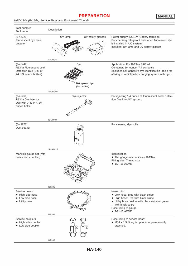
Tool numberTool name
Description
(J-42220)Fluorescent dye leakdetector
UV lamp UV safety glasses
SHA438F
Power supply: DC12V (Battery terminal)For checking refrigerant leak when fluorescent dyeis installed in A/C system.Includes: UV lamp and UV safety glasses
(J-41447)R134a Fluorescent LeakDetection Dye (Box of24, 1/4 ounce bottles)
Dye
SHA439F
Application: For R-134a PAG oilContainer: 1/4 ounce (7.4 cc) bottle(Includes self-adhesive dye identification labels foraffixing to vehicle after charging system with dye.)
(J-41459)R134a Dye InjectorUse with J-41447, 1/4ounce bottle
Dye injector
SHA440F
For injecting 1/4 ounce of Fluorescent Leak Detec-tion Dye into A/C system.
(J-43872)Dye cleaner
SHA441F
For cleaning dye spills.
Manifold gauge set (withhoses and couplers)
NT199
Identification:+ The gauge face indicates R-134a.Fitting size: Thread size+ 1/2″-16 ACME
Service hoses+ High side hose+ Low side hose+ Utility hose
NT201
Hose color:+ Low hose: Blue with black stripe+ High hose: Red with black stripe+ Utility hose: Yellow with black stripe or green
with black stripeHose fitting to gauge:+ 1/2″-16 ACME
Service couplers+ High side coupler+ Low side coupler
NT202
Hose fitting to service hose:+ M14 x 1.5 fitting is optional or permanently
attached.
PREPARATION MANUALHFC-134a (R-134a) Service Tools and Equipment (Cont’d)
HA-140

Tool numberTool name
Description
Refrigerant weight scale
NT200
For measuring of refrigerantFitting size: Thread size+ 1/2″-16 ACME
Vacuum pump(Including the isolatorvalve)
NT203
Capacity:+ Air displacement: 4 CFM+ Micron rating: 20 microns+ Oil capacity: 482 g (17 oz)Fitting size: Thread size+ 1/2″-16 ACME
PREPARATION MANUALHFC-134a (R-134a) Service Tools and Equipment (Cont’d)
HA-141

Refrigeration SystemREFRIGERATION CYCLE
NFHA0069
Refrigerant FlowNFHA0069S01
The refrigerant flows in the standard pattern, that is, through the compressor, the condenser, the liquid tank,through the evaporator, and back to the compressor. The refrigerant evaporation through the evaporator coilis controlled by an externally equalized expansion valve, located inside the evaporator case.
Freeze ProtectionNFHA0069S02
Under normal operating conditions, when the A/C is switched on, the compressor runs continuously, and theevaporator pressure, and therefore, temperature is controlled by the V-6 variable displacement compressor toprevent freeze up.
Refrigerant System ProtectionNFHA0069S03
Refrigerant Pressure SensorNFHA0069S0301
The refrigerant system is protected against excessively high or low pressures by the refrigerant pressuresensor, located on the liquid tank. If the system pressure rises above, or falls below the specifications, therefrigerant pressure sensor detects the pressure inside the refrigerant line and sends the voltage signal to theECM. ECM makes the A/C relay go OFF and stops the compressor when pressure on the high pressure sidedetected by refrigerant pressure sensor is over about 2,746 kPa (27.5 bar, 28 kg/cm2, 398 psi) or below about137 kPa (1.37 bar, 1.4 kg/cm2, 20 psi).Pressure Relief Valve
NFHA0069S0302
The refrigerant system is also protected by a pressure relief valve, located in the rear head of the compres-sor. When the pressure of refrigerant in the system increases to an abnormal level [more than 3,727 kPa (37.3bar, 38 kg/cm2, 540 psi)], the release port on the pressure relief valve automatically opens and releasesrefrigerant into the atmosphere.
RHA347H
DESCRIPTION MANUALRefrigeration System
HA-142

V-6 Variable Displacement CompressorGENERAL INFORMATION
=NFHA0070
1. The V-6 variable compressor differs from previous units. The vent temperatures of the V-6 variable com-press do not drop too far below 5°C (41°F) when:
+ evaporator intake air temperature is less than 20°C (68°F)+ engine is running at speeds less than 1,500 rpm.
This is because the V-6 compressor provides a means of “capacity” control.2. The V-6 variable compressor provides refrigerant control under varying conditions. During cold winters, it
may not produce high refrigerant pressure discharge (compared to previous units) when used with airconditioning systems.
3. A “clanking” sound may occasionally be heard during refrigerant charge. The sound indicates that the tiltangle of the swash plate has changed and is not a problem.
4. For air conditioning systems with the V-6 compressor, the clutch remains engaged unless: the system mainswitch, fan switch or ignition switch is turned OFF. When ambient (outside) temperatures are low or whenthe amount of refrigerant is insufficient, the clutch is disengaged to protect the compressor.
5. A constant range of suction pressure is maintained when engine speed is greater than a certain value. Itnormally ranges from 147 to 177 kPa (1.47 to 1.77 bar, 1.5 to 1.8 kg/cm2, 21 to 26 psi) under varying con-ditions.In previous compressors, however, suction pressure was reduced with increases in engine speed.
DESCRIPTION MANUALV-6 Variable Displacement Compressor
HA-143
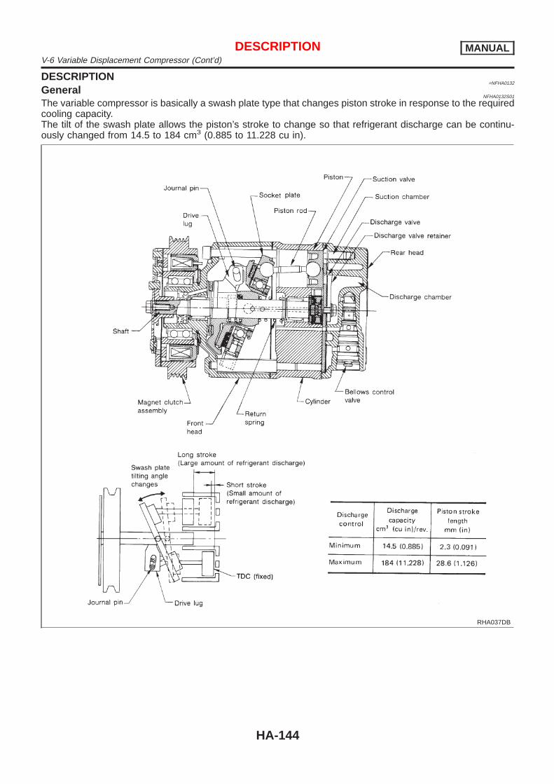
DESCRIPTION=NFHA0132
GeneralNFHA0132S01
The variable compressor is basically a swash plate type that changes piston stroke in response to the requiredcooling capacity.The tilt of the swash plate allows the piston’s stroke to change so that refrigerant discharge can be continu-ously changed from 14.5 to 184 cm3 (0.885 to 11.228 cu in).
RHA037DB
DESCRIPTION MANUALV-6 Variable Displacement Compressor (Cont’d)
HA-144
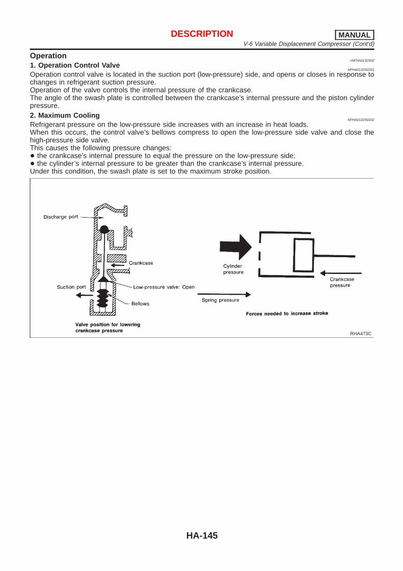
Operation=NFHA0132S02
1. Operation Control ValveNFHA0132S0201
Operation control valve is located in the suction port (low-pressure) side, and opens or closes in response tochanges in refrigerant suction pressure.Operation of the valve controls the internal pressure of the crankcase.The angle of the swash plate is controlled between the crankcase’s internal pressure and the piston cylinderpressure.2. Maximum Cooling
NFHA0132S0202
Refrigerant pressure on the low-pressure side increases with an increase in heat loads.When this occurs, the control valve’s bellows compress to open the low-pressure side valve and close thehigh-pressure side valve.This causes the following pressure changes:+ the crankcase’s internal pressure to equal the pressure on the low-pressure side;+ the cylinder’s internal pressure to be greater than the crankcase’s internal pressure.Under this condition, the swash plate is set to the maximum stroke position.
RHA473C
DESCRIPTION MANUALV-6 Variable Displacement Compressor (Cont’d)
HA-145
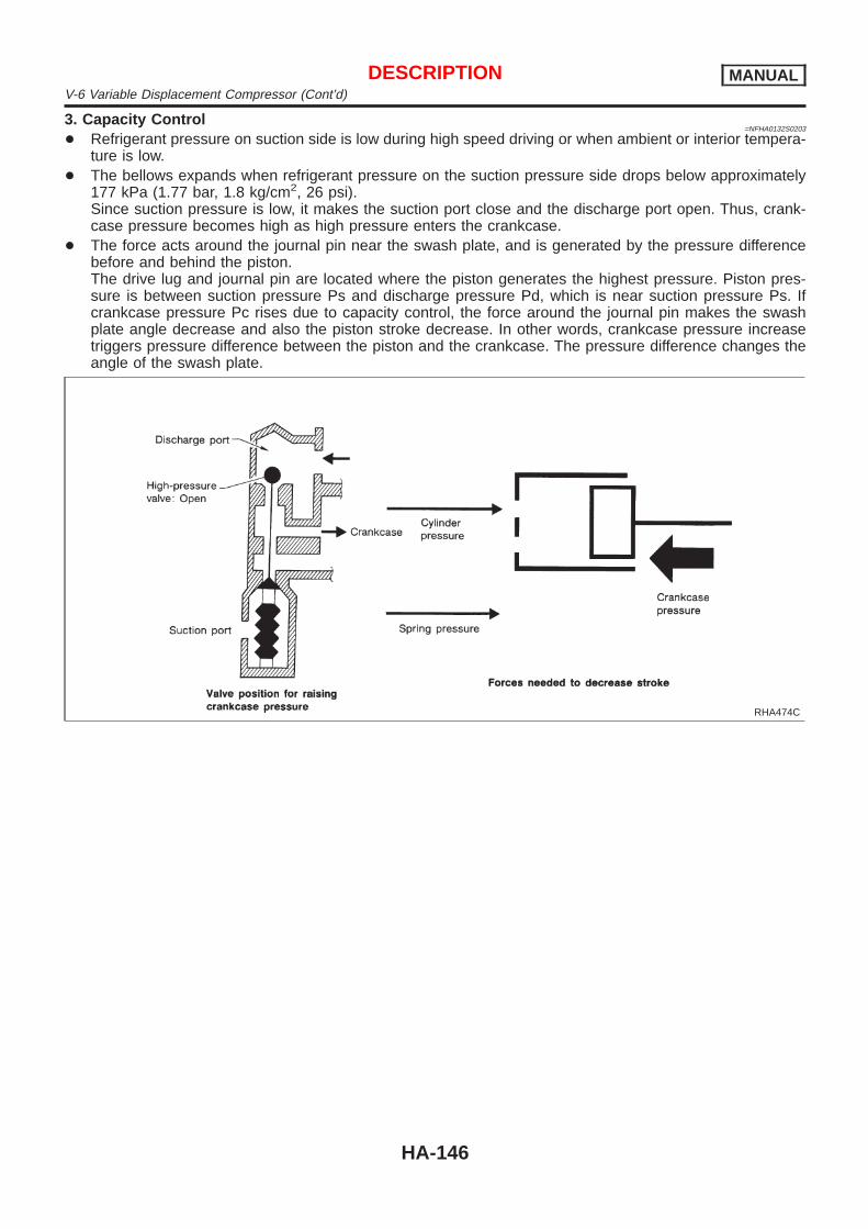
3. Capacity Control=NFHA0132S0203
+ Refrigerant pressure on suction side is low during high speed driving or when ambient or interior tempera-ture is low.
+ The bellows expands when refrigerant pressure on the suction pressure side drops below approximately177 kPa (1.77 bar, 1.8 kg/cm2, 26 psi).Since suction pressure is low, it makes the suction port close and the discharge port open. Thus, crank-case pressure becomes high as high pressure enters the crankcase.
+ The force acts around the journal pin near the swash plate, and is generated by the pressure differencebefore and behind the piston.The drive lug and journal pin are located where the piston generates the highest pressure. Piston pres-sure is between suction pressure Ps and discharge pressure Pd, which is near suction pressure Ps. Ifcrankcase pressure Pc rises due to capacity control, the force around the journal pin makes the swashplate angle decrease and also the piston stroke decrease. In other words, crankcase pressure increasetriggers pressure difference between the piston and the crankcase. The pressure difference changes theangle of the swash plate.
RHA474C
DESCRIPTION MANUALV-6 Variable Displacement Compressor (Cont’d)
HA-146

IACV-AAC CONTROL SYSTEM=NFHA0133
OperationNFHA0133S02
When the air conditioner is OFF, the ECM detects the load applied to the engine, and controls the IACV-AACvalve to adjust the engine idling speed to the appropriate rpm by supplying additional air from the IACV-AACvalve.When the air conditioner is ON (A/C relay is ON), refrigerant-pressure sensor converts refrigeration-pressureon the high pressure side into the voltage value, which is output to ECM which protects refrigeration cycle andcontrol idle speed by the output voltage data, and additional air is supplied to the engine. If the appropriateengine speed is not reached, the IACV-AAC valve supplies the additional air required to increase the enginerpm.
DESCRIPTION MANUALV-6 Variable Displacement Compressor (Cont’d)
HA-147

Component LayoutNFHA0071
RHA349HA
DESCRIPTION MANUALComponent Layout
HA-148

Control OperationNFHA0072
SHA337F
FAN CONTROL DIALNFHA0072S01
This dial turns the fan ON and OFF, and controls fan speed.
MODE SWITCHESNFHA0072S02
This switch allows control of the outlet air flow.In “DEF” or “D/F” mode, the intake door is set to “FRESH”.The compressor turns on when the Mode switch is moved to “DEF”.
TEMPERATURE CONTROL LEVERNFHA0072S03
This lever allows adjustment of the temperature of the outlet air.
RECIRCULATION (REC) SWITCHNFHA0072S04
OFF position: Outside air is drawn into the passenger compartment.ON position: Interior air is recirculated inside the vehicle. The indicator lamp will also light.Recirculation is canceled when DEF or D/F is selected, and resumes when another mode is chosen.If the refrigerant pressure sensor input signal is high, recirculation is canceled, when VENT, B/L and FOOTmode is selected.
AIR CONDITIONER SWITCHNFHA0072S05
The air conditioner switch controls the A/C system. When the switch is depressed with the fan ON, the com-pressor will turn ON. The indicator lamp will also light.The air conditioner cooling function operates only when the engine is running.
REAR WINDOW DEFOGGER SWITCHNFHA0072S06
When illumination is ON, rear window is defogging.
DESCRIPTION MANUALControl Operation
HA-149

Discharge Air FlowNFHA0073
SHA424FA
DESCRIPTION MANUALDischarge Air Flow
HA-150

System DescriptionNFHA0074
SWITCHES AND THEIR CONTROL FUNCTIONSNFHA0074S01
SHA378F
SHA443FA
DESCRIPTION MANUALSystem Description
HA-151

Component LocationNFHA0085
ENGINE COMPARTMENTNFHA0085S01
RHA455H
TROUBLE DIAGNOSES MANUALComponent Location
HA-152

PASSENGER COMPARTMENTNFHA0085S02
RHA456HA
TROUBLE DIAGNOSES MANUALComponent Location (Cont’d)
HA-153

Circuit Diagram — Air ConditionerNFHA0087
MHA936A
TROUBLE DIAGNOSES MANUALCircuit Diagram — Air Conditioner
HA-154

Wiring Diagram — A/C, Heater —NFHA0265
MHA027B
TROUBLE DIAGNOSES MANUALWiring Diagram — A/C, Heater —
HA-155

Wiring Diagram — A/C, M —NFHA0088
MHA937A
TROUBLE DIAGNOSES MANUALWiring Diagram — A/C, M —
HA-156

MHA938A
TROUBLE DIAGNOSES MANUALWiring Diagram — A/C, M — (Cont’d)
HA-157

MHA939A
TROUBLE DIAGNOSES MANUALWiring Diagram — A/C, M — (Cont’d)
HA-158

MHA998A
TROUBLE DIAGNOSES MANUALWiring Diagram — A/C, M — (Cont’d)
HA-159

How to Perform Trouble Diagnoses for Quickand Accurate Repair
NFHA0075
WORK FLOWNFHA0075S01
SHA900E
*1: HA-161
SYMPTOM TABLENFHA0075S02
Symptom Reference page
+ A/C system does not come on. + Go to Trouble Diagnosis Procedure for A/C system. HA-163
+ Mode door does not change. + Go to Trouble Diagnosis Procedure for Mode door. HA-166
+ Air mix door motor does not operate normally. + Go to Trouble Diagnosis Procedure for Air mix doormotor.
HA-169
+ Intake door does not change in VENT, B/L or FOOTmode.
+ Go to Trouble Diagnosis Procedure for Intake Door. HA-173
+ Blower motor does not rotate at all. + Go to Trouble Diagnosis Procedure for Blower Motor. HA-177
+ Magnet clutch does not engage when A/C switch andfan switch are ON.
+ Go to Trouble Diagnosis Procedure for Magnet Clutch. HA-183
+ Insufficient cooling. + Go to Trouble Diagnosis Procedure for Insufficientcooling.
HA-190
+ Insufficient heating. + Go to Trouble Diagnosis Procedure for Insufficientheating.
HA-198
+ Noise + Go to Trouble Diagnosis Procedure for Noise. HA-199
TROUBLE DIAGNOSES MANUALHow to Perform Trouble Diagnoses for Quick and Accurate Repair
HA-160

Operational Check=NFHA0076
The purpose of the operational check is to confirm that the systemoperates as it should. The systems which are checked are theblower, mode (discharge air), intake air, temperature decrease,temperature increase.
CONDITIONS:NFHA0076S01
Engine running at normal operating temperature.
RHA424H
PROCEDURE:NFHA0076S02
1. Check BlowerNFHA0076S0201
1. Turn fan control dial to 1-speed.Blower should operate on 1-speed.
2. Then turn fan control dial to 2-speed.3. Continue checking blower speed until all four speeds are
checked.4. Leave blower on 4-speed.If NG, go to trouble diagnosis procedure for blower motor (HA-177).If OK, continue with next check.
RHA425H
2. Check Discharge AirNFHA0076S0202
1. Press each mode switch.
SHA345FB
2. Confirm that discharge air comes out according to the air dis-tribution table at left.Refer to “Discharge Air Flow” in “DESCRIPTION” (HA-150).
NOTE:Confirm that the compressor clutch is engaged (visual inspection)and intake door position is at FRESH when the DEF ( )is pressed.Confirm that the intake door position is at FRESH when the D/F( ) is pressed.Intake door position is checked in the next step.If NG, go to trouble diagnosis procedure for mode door motor(HA-166).If OK, continue with next check.
TROUBLE DIAGNOSES MANUALOperational Check
HA-161

RHA426H
3. Check RecirculationNFHA0076S0203
1. Press recirculation switch.Recirculation indicator should light.
2. Listen for intake door position change (you should hear blowersound change slightly).
NOTE:Confirm that the RECIRCULATION (REC) switch is canceled in theDEF ( ) and D/F ( ) mode.If NG, go to trouble diagnosis procedure for intake door motor(HA-173).If OK, continue with next check.
RHA427H
4. Check Temperature DecreaseNFHA0076S0204
1. Slide temperature control lever to full cold.2. Check for cold air at discharge air outlets.If NG, go to trouble diagnosis procedure for insufficient coolingmotor (HA-190).If OK, continue with next check.
RHA428H
5. Check Temperature IncreaseNFHA0076S0205
1. Slide temperature control lever to full hot.2. Check for hot air at discharge air outlets.If NG, go to trouble diagnosis procedure for insufficient heatingmotor (HA-198).If OK, continue with next check.
RHA429H
6. Check Air Conditioner SwitchNFHA0076S0206
Turn fan control switch to the desired (1 to 4-speed) position andpush the air conditioner switch to turn ON the air conditioner.The indicator light should come on when air conditioner is ON.If NG, go to trouble diagnosis procedure for A/C system (HA-163).If OK, continue with next check.If all operational check are OK (symptom can not be duplicated),go to “Incident Simulation Tests” (GI-22) and perform tests as out-lined to simulate driving conditions environment. If symptomappears, refer to “Symptom Table” (HA-160) and perform appli-cable trouble diagnosis procedures.
TROUBLE DIAGNOSES MANUALOperational Check (Cont’d)
HA-162

A/C SystemTROUBLE DIAGNOSIS PROCEDURE FOR A/C SYSTEM
=NFHA0253
Symptom:+ A/C system does not come on.INSPECTION FLOW
RHA569H
*1: HA-164 *2: HA-161 *3: HA-154
TROUBLE DIAGNOSES MANUALA/C System
HA-163

MAIN POWER SUPPLY AND GROUND CIRCUIT CHECK=NFHA0254
Power Supply Circuit CheckNFHA0254S01
Check power supply circuit for air conditioner system.Refer to EL-10, “Wiring Diagram — POWER —”.
DIAGNOSTIC PROCEDURENFHA0255
SYMPTOM:+ A/C system does not come on.
1 CHECK POWER SUPPLY CIRCUIT FOR A/C CONTROL UNIT
Measure voltage across terminal No. 14 and body ground.
RHA386HA
MTBL0323
OK or NG
OK © GO TO 2.
NG © Check 10A fuse (No. 19) at fuse block.
TROUBLE DIAGNOSES MANUALA/C System (Cont’d)
HA-164

2 CHECK BODY GROUND CIRCUIT FOR A/C CONTROL UNIT
Check for continuity between terminal No. 17 and body ground.
RHA391H
MTBL0324
OK or NG
OK © INSPECTION END
NG © If NG, repair harness or connector.
TROUBLE DIAGNOSES MANUALA/C System (Cont’d)
HA-165

Mode DoorTROUBLE DIAGNOSIS PROCEDURE FOR MODE DOOR
=NFHA0142
Symptom:+ Air outlet does not change.Inspection Flow
RHA445HB
*1: HA-168*2: HA-161
*3: HA-160*4: HA-150
*5: HA-167
TROUBLE DIAGNOSES MANUALMode Door
HA-166

DIAGNOSTIC PROCEDURE=NFHA0260
SYMPTOM:+ Mode door motor does not operate normally.
1 CHECK POWER SUPPLY FOR A/C CONTROL UNIT
Refer to “MAIN POWER SUPPLY AND GROUND CIRCUIT CHECK”, HA-164.
OK or NG
OK © GO TO 2.
NG © Repair or replace.
2 CHECK FOR OUTPUT OF A/C CONTROL UNIT
Do approx. 10.5 volts exist between mode door motor harness terminal Nos. 8, 9 and body ground?
SHA328F
Yes or No
Yes © GO TO 4.
No © GO TO 3.
3 CHECK CIRCUIT CONTINUITY BETWEEN MODE DOOR MOTOR AND A/C CONTROL UNIT
Check circuit continuity between mode door motor harness terminal Nos. 8, (9) and A/C control unit harness terminal Nos.7, (8).
RHA574H
Continuity should exist.If OK, check harness for short.
OK or NG
OK © Replace A/C control unit.
NG © Repair harness or connector.
TROUBLE DIAGNOSES MANUALMode Door (Cont’d)
HA-167

4 CHECK CIRCUIT CONTINUITY BETWEEN MODE DOOR MOTOR AND A/C CONTROL UNIT
Check circuit continuity between mode door motor harness terminal and A/C control unit harness terminal.
RHA395HB
Continuity should exist.If OK, check harness for short.
OK or NG
OK © Replace air mix door motor.
NG © Repair harness or connector.
RHA371H
CONTROL LINKAGE ADJUSTMENTNFHA0151
Mode DoorNFHA0151S01
1. Install mode door motor on heater unit and connect it to mainharness.Make sure lever of mode door motor is fitted into the slit ofmode door link.
2. Turn ignition switch to ON.3. Turn VENT switch ON.4. Turn DEF switch ON. Check that slide link operates at the full-
open position.Also turn DEF switch ON to check that slide link operates atthe fully-open position.
TROUBLE DIAGNOSES MANUALMode Door (Cont’d)
HA-168

Air Mix DoorTROUBLE DIAGNOSIS PROCEDURE FOR AIR MIX DOOR MOTOR
=NFHA0256
SYMPTOM:+ Air mix door motor does not operate normally.INSPECTION FLOW
SHA335F
*1: HA-172 *2: HA-171 *3: HA-161
TROUBLE DIAGNOSES MANUALAir Mix Door
HA-169

RHA644F
CONTROL SYSTEM INPUT COMPONENTNFHA0258
PBRNFHA0258S01
Measure resistance between terminals 1 and 2 at vehicle harnessside.
RHA645F
TROUBLE DIAGNOSES MANUALAir Mix Door (Cont’d)
HA-170

DIAGNOSTIC PROCEDURE=NFHA0259
SYMPTOM:+ Air mix door motor does not operate normally.
1 CHECK POWER SUPPLY FOR A/C CONTROL UNIT
Refer to “MAIN POWER SUPPLY AND GROUND CIRCUIT CHECK”, HA-164.
OK or NG
OK © GO TO 2.
NG © Repair or replace.
2 CHECK PBR
Refer to HA-170.
OK or NG
OK © GO TO 3.
NG © Replace air mix door motor.
3 CHECK FOR OUTPUT OF AUTO AMP.
Do approx. 10.5 volts exist between air mix door motor harness terminal Nos. 4, 5 and body ground?
SHA327F
Yes or No
Yes © GO TO 4.
No © Replace A/C control unit.
4 CHECK POWER SUPPLY FOR PBR.
Do approx. 12 volts exist between air mix door motor harness terminal No. 3 and body ground?
RHA572H
Yes or No
Yes © GO TO 5.
No © Check 10A (No. 19) fuse at fuse block. Refer to EL-10, “Wiring Diagram — POWER —”.
TROUBLE DIAGNOSES MANUALAir Mix Door (Cont’d)
HA-171

5 CHECK GROUND CIRCUIT FOR PBR.
Check circuit continuity between air mix door motor harness terminal No. 1 and body ground.
RHA573H
OK or NG
OK © GO TO 6.
NG © Repair harness or connector.
6 CHECK CIRCUIT CONTINUITY BETWEEN AIR MIX DOOR MOTOR AND A/C CONTROL UNIT
Check circuit continuity between air mix door motor harness terminal Nos. (4), 5 and A/C control unit harness terminalNos. (22), 23.
RHA380H
Continuity should exist.If OK, check harness for short.
OK or NG
OK © Replace air mix door motor.
NG © Repair harness or connector.
RHA379H
CONTROL LINKAGE ADJUSTMENTNFHA0257
Air Mix DoorNFHA0257S01
1. Install air mix door motor on heater unit and connect it to mainharness.Make sure lever of air mix door is fitted into the slit of the airmix door link.
2. Turn ignition switch to ON.3. Slide temperature control lever to full cold.4. Check that air mix door operates properly when temperature
control lever is slid to full hot and full cold.
TROUBLE DIAGNOSES MANUALAir Mix Door (Cont’d)
HA-172

Intake DoorTROUBLE DIAGNOSIS PROCEDURE FOR INTAKE DOOR
=NFHA0135
Symptom:+ Intake door does not change in VENT, B/L or FOOT mode.Inspection Flow
RHA430HA
*1: HA-174 *2: HA-161 *3: HA-160
RHA570HA
SYSTEM DESCRIPTIONNFHA0136
Intake Door MotorNFHA0136S01
The intake door motor is installed on the blower and intake unit.Using a link it opens and closes the intake door.When RECIRCULATION switch is at REC (except DEF and D/Fmodes), the A/C control unit sets the intake door at the “RECIR-CULATION” position.RECIRCULATION switch is canceled by MODE switch in DEF andD/F modes.
TROUBLE DIAGNOSES MANUALIntake Door
HA-173

RHA385H
RHA571H
DIAGNOSTIC PROCEDURENFHA0090
SYMPTOM: Intake door motor does not operate normally.
1 CHECK BODY GROUND CIRCUIT FOR INTAKE DOOR MOTOR
Does continuity exist between intake door harness terminal No. 5 and body ground?
RHA433H
Yes or No
Yes © GO TO 2.
No © Repair harness or connector.
TROUBLE DIAGNOSES MANUALIntake Door (Cont’d)
HA-174

2 CHECK FOR A/C CONTROL UNIT OUTPUT
Measure voltage across auto amp. harness terminals and body ground.
SHA324FA
OK or NG
OK © GO TO 3.
NG © Replace A/C control unit.
3 CHECK CIRCUIT CONTINUITY BETWEEN A/C CONTROL UNIT AND INTAKE DOOR MOTOR
Check circuit continuity between each terminal on A/C control unit and on intake door motor.
RHA435HA
Continuity should exist.If OK, check harness for short.
OK or NG
OK © Replace intake door motor.
NG © Repair harness or connector.
TROUBLE DIAGNOSES MANUALIntake Door (Cont’d)
HA-175

RHA385H
CONTROL LINKAGE ADJUSTMENTNFHA0093
Intake Door MotorNFHA0093S04
1. Install intake door motor on blower and intake unit.Ensure that the intake door motor lever is fitted into the slitportion of intake door link.
2. Connect the intake door motor harness connector.3. Turn ignition switch to ON.4. Check that intake door operates properly when RECIRCULA-
TION switch is turned ON and OFF.
TROUBLE DIAGNOSES MANUALIntake Door (Cont’d)
HA-176

Blower MotorTROUBLE DIAGNOSIS PROCEDURE FOR BLOWER MOTOR
=NFHA0138
Symptom:+ Blower motor does not rotate at all.Inspection Flow
RHA437HA
*1: HA-179 *2: HA-161 *3: HA-160
TROUBLE DIAGNOSES MANUALBlower Motor
HA-177

RHA438H
ELECTRICAL COMPONENTS INSPECTION=NFHA0139
Fan SwitchNFHA0139S01
Check continuity between terminals at each switch position.
SWITCH POSITION Continuity between terminals
OFF No continuity
1 2 — 1 — 6
2 3 — 1 — 6
3 4 — 1 — 6
4 5 — 1 — 6
Blower MotorNFHA0139S02
Confirm smooth rotation of the blower motor.+ Ensure that there are no foreign particles inside the intake unit.
RHA651F
Blower ResistorNFHA0139S03
Check resistance between terminals.
Terminal No. Resistance
(+) (−) RHD models LHD models
3
1
Approx. 1.29 - 1.57Ω Approx. 0.9 - 1.1Ω
4 Approx. 2.7 - 3.3Ω Approx. 2.57 - 3.14Ω
2 Approx. 0.45 - 0.56Ω Approx. 0.36 - 0.44Ω
TROUBLE DIAGNOSES MANUALBlower Motor (Cont’d)
HA-178
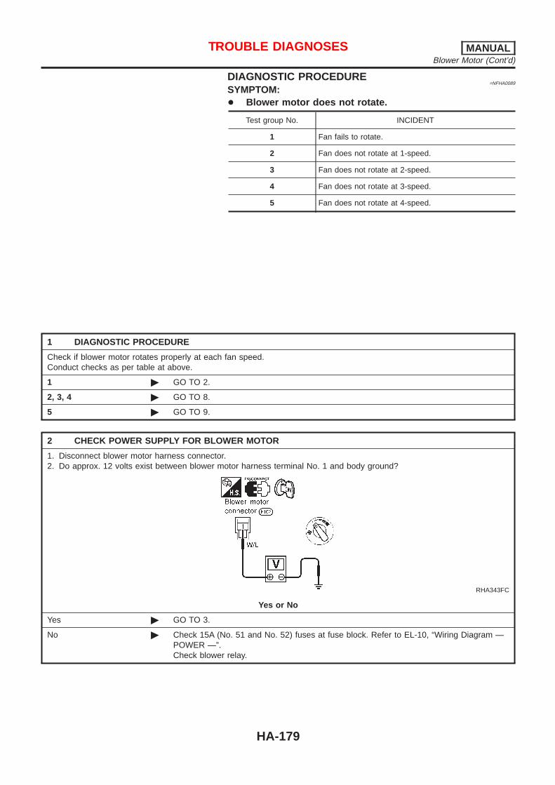
DIAGNOSTIC PROCEDURE=NFHA0089
SYMPTOM:+ Blower motor does not rotate.
Test group No. INCIDENT
1 Fan fails to rotate.
2 Fan does not rotate at 1-speed.
3 Fan does not rotate at 2-speed.
4 Fan does not rotate at 3-speed.
5 Fan does not rotate at 4-speed.
1 DIAGNOSTIC PROCEDURE
Check if blower motor rotates properly at each fan speed.Conduct checks as per table at above.
1 © GO TO 2.
2, 3, 4 © GO TO 8.
5 © GO TO 9.
2 CHECK POWER SUPPLY FOR BLOWER MOTOR
1. Disconnect blower motor harness connector.2. Do approx. 12 volts exist between blower motor harness terminal No. 1 and body ground?
RHA343FC
Yes or No
Yes © GO TO 3.
No © Check 15A (No. 51 and No. 52) fuses at fuse block. Refer to EL-10, “Wiring Diagram —POWER —”.Check blower relay.
TROUBLE DIAGNOSES MANUALBlower Motor (Cont’d)
HA-179

3 CHECK CIRCUIT CONTINUITY FOR BLOWER MOTOR
1. Turn fan control switch to any position except OFF.2. Check circuit continuity between blower motor harness terminal No. 2 and body ground.
RHA344FC
Continuity should exist.If OK, check harness for short.
OK or NG
OK © GO TO 4.
NG © Reconnect blower motor harness connector. GO TO 5.
4 CHECK BLOWER MOTOR
(Refer to Electrical Components Inspection.)(HA-178)
OK or NG
OK © INSPECTION END
NG © Replace blower motor.
5 CHECK BLOWER MOTOR CIRCUIT BETWEEN BLOWER MOTOR AND RESISTOR
Do approx. 12 volts exist between resistor harness terminal No. 1 and body ground?
RHA575FB
Yes or No
Yes © Disconnect fan switch harness connector. GO TO 7.
No © Disconnect blower motor and resistor harness connectors. GO TO 6.
TROUBLE DIAGNOSES MANUALBlower Motor (Cont’d)
HA-180

6 CHECK CIRCUIT CONTINUITY BETWEEN BLOWER MOTOR AND RESISTOR
Check circuit continuity between blower motor harness terminal No. 2 and resistor harness terminal No. 1.
RHA576FB
Continuity should exist.If OK, check harness for short.
OK or NG
NG © Repair harness or connector.
7 CHECK GROUND CIRCUIT FOR FAN SWITCH
Check circuit continuity between fan switch harness terminal No. 1 and body ground.
RHA440H
OK or NG
OK © GO TO 8.
NG © Repair harness or connector.
8 CHECK RESISTOR AFTER DISCONNECTING IT
(Refer to Electrical Components Inspection.)(HA-178)
OK or NG
OK © Reconnect resistor harness connector. GO TO 9.
NG © Replace resistor.
TROUBLE DIAGNOSES MANUALBlower Motor (Cont’d)
HA-181

9 CHECK FAN SWITCH CIRCUIT
Do approx. 12 volts exist between each fan switch harness terminal and body ground?
SHA325F
Yes or No
Yes © GO TO 11.
No © GO TO 10.
10 CHECK CIRCUIT CONTINUITY BETWEEN FAN SWITCH AND RESISTOR
Check circuit continuity between fan switch harness terminal and resistor harness terminal.
SHA326F
Continuity should exist.If OK, check harness for short.
OK or NG
NG © Repair harness or connector.
11 CHECK FAN SWITCH AFTER DISCONNECTING IT
(Refer to Electrical Components Inspection.)(HA-178)
OK or NG
OK © INSPECTION END
NG © Replace fan switch.
TROUBLE DIAGNOSES MANUALBlower Motor (Cont’d)
HA-182

Magnet ClutchTROUBLE DIAGNOSIS PROCEDURE FOR MAGNET CLUTCH
=NFHA0119
Symptom:+ Magnet clutch does not operate when A/C switch and fan switch are ON.Inspection Flow
RHA446HA
*1: HA-214*2: HA-184
*3: HA-161*4: HA-160
*5: MA-15
TROUBLE DIAGNOSES MANUALMagnet Clutch
HA-183

DIAGNOSTIC PROCEDURE=NFHA0091
SYMPTOM:+ Magnet clutch does not engage when A/C switch and fan
switch are ON.
1 CHECK POWER SUPPLY FOR COMPRESSOR
Disconnect compressor harness connector.Do approx. 12 volts exist between compressor harness terminal No. 1 and body ground?
RHA747FH
Yes or No
Yes © GO TO 2.
No © Disconnect A/C relay. GO TO 3.
2 CHECK MAGNET CLUTCH COIL
OK or NG
NG © Replace magnet clutch. Refer to HA-205.
3 CHECK CIRCUIT CONTINUITY BETWEEN A/C RELAY AND COMPRESSOR
Check circuit continuity between A/C relay harness terminal No. 3 and compressor harness terminal No. 1.
RHA447H
Continuity should exist.If OK, check harness for short.
OK or NG
OK © GO TO 4.
NG © Repair harness or connector.
TROUBLE DIAGNOSES MANUALMagnet Clutch (Cont’d)
HA-184

4 CHECK POWER SUPPLY FOR A/C RELAY
Disconnect A/C relay.Do approx. 12 volts exist between A/C relay harness terminal Nos. 1, 5 and body ground?
RHA439HA
Yes or No
Yes © GO TO 5.
No © Check power supply circuit and 10A (No. 19, 66) fuse at fuse block. Refer to EL-10,“Wiring Diagram — POWER —”.
5 CHECK A/C RELAY AFTER DISCONNECTING IT
Refer to HA-189.
OK or NG
OK © Reconnect A/C relay. GO TO 6.
NG © Replace A/C relay.
6 CHECK COIL SIDE CIRCUIT OF A/C RELAY
Do approx. 12 volts exist between ECM harness terminal No. 27 and body ground?
SHA311FA
Yes or No
Yes © GO TO 8.
No © Disconnect A/C relay. Disconnect ECM harness connector. GO TO 7.
TROUBLE DIAGNOSES MANUALMagnet Clutch (Cont’d)
HA-185

7 CHECK CIRCUIT CONTINUITY BETWEEN A/C RELAY AND ECM
Check circuit continuity between A/C relay harness terminal No. 2 and ECM harness terminal No. 27.
RHA448H
Continuity should exist.If OK, check harness for short.
OK or NG
NG © Repair harness or connector.
8 CHECK REFRIGERANT PRESSURE SENSOR INPUT SIGNAL
Do approx. 0 volts between ECM harness terminal No. 51 and body ground?
RHA575H
Yes or No
Yes © GO TO 10.
No © Check ECM. Refer to EC-114, “ECM Terminals and Reference Value”.Repair harness or connector.
9 CHECK REFRIGERANT PRESSURE SENSOR
Refer to HA-189.
OK or NG
OK © Disconnect A/C switch harness connector. GO TO 10.
NG © Replace refrigerant pressure sensor.
TROUBLE DIAGNOSES MANUALMagnet Clutch (Cont’d)
HA-186

10 CHECK VOLTAGE FOR ECM
Do approx. 12 volts exist between ECM harness terminal No. 45 and body ground?
SHA312F
Yes or No
Yes © GO TO 11.
No © Check ECM. Refer to EC-114, “ECM Terminals and Reference Value”.Repair harness or connector.
11 CHECK CIRCUIT CONTINUITY BETWEEN A/C CONTROL UNIT AND FAN SWITCH
Check circuit continuity between A/C control unit harness terminal No. 12 and fan switch harness terminal No. 6.
RHA450H
Continuity should exist.If OK, check harness for short.
OK or NG
OK © GO TO 12.
NG © Repair harness or connector.
TROUBLE DIAGNOSES MANUALMagnet Clutch (Cont’d)
HA-187

12 CHECK BODY GROUND CIRCUIT FOR FAN SWITCH
Does continuity exist between fan switch harness terminal No. 1 and body ground?
RHA451H
Yes or No
Yes © GO TO 13.
No © Repair harness or connector.
13 CHECK FAN SWITCH
Refer to HA-178.
OK or NG
OK © Replace A/C control unit.
NG © Replace fan switch.
TROUBLE DIAGNOSES MANUALMagnet Clutch (Cont’d)
HA-188

SEF090M
ELECTRICAL COMPONENTS INSPECTION=NFHA0092
A/C RelayNFHA0092S07
Check continuity between terminal Nos. 3 and 5.
Conditions Continuity
12V direct current supply between terminal Nos. 1and 2
Yes
No current supply No
If NG, replace relay.
RHA404H
RHA976H
SHA315FC
Refrigerant Pressure SensorNFHA0092S08
Make sure that higher A/C refrigerant pressure results in higherrefrigerant-pressure sensor output voltage.
OFFkPa (bar, kg/cm2, psi)
Low-pressure sideDecreasing to 0.18
(0.0018, 0.00184, 0.03)
High-pressure sideIncreasing to 2.74
(0.0274, 0.0279, 0.40)
Refer to EC-550, “Diagnostic Procedure”.
TROUBLE DIAGNOSES MANUALMagnet Clutch (Cont’d)
HA-189

Insufficient CoolingTROUBLE DIAGNOSIS PROCEDURE FOR INSUFFICIENT COOLING
=NFHA0150
Symptom:+ Insufficient Cooling.Inspection Flow
SHA418FA
*1: HA-169*2: HA-193*3: HA-191
*4: HA-161*5: HA-160*6: HA-205
*7: HA-169*8: MA-15*9: EC-351
TROUBLE DIAGNOSES MANUALInsufficient Cooling
HA-190

PERFORMANCE TEST DIAGNOSESNFHA0082
SHA419F
*1: HA-193*2: HA-193
*3: HA-194 *4: HA-169
TROUBLE DIAGNOSES MANUALInsufficient Cooling (Cont’d)
HA-191

SHA334F
*7: HA-207 *8: HA-177 *9: MA-15
TROUBLE DIAGNOSES MANUALInsufficient Cooling (Cont’d)
HA-192

PERFORMANCE TEST=NFHA0083
Test ConditionNFHA0083S01
Testing must be performed as follows:
Vehicle location Indoors or in the shade (in a well-ventilated place)
Doors Closed
Door windows Open
Hood Open
TEMP. Max. COLD
Discharge Air Face Vent
REC switch (Recirculation) set
FAN speed High speed
Engine speed Idle speed
Operate the air conditioning system for 10 minutes before taking measurements.
Test ReadingNFHA0083S02
Recirculating-to-discharge Air Temperature TableNFHA0083S0201
Inside air (Recirculating air) at blower assembly inletDischarge air temperature at center ventilator °C (°F)
Relative humidity % Air temperature °C (°F)
50 - 60
15 (59) 3.5 - 5.4 (38 - 42)
20 (68) 6.6 - 8.9 (44 - 48)
25 (77) 9.5 - 12.6 (49 - 55)
30 (86) 13.4 - 16.5 (56 - 62)
35 (95) 17.6 - 21.3 (64 - 70)
60 - 70
15 (59) 5.4 - 7.1 (42 - 45)
20 (68) 8.9 - 11.0 (48 - 52)
25 (77) 12.6 - 15.4 (55 - 60)
30 (86) 16.5 - 20.0 (62 - 68)
35 (95) 21.3 - 24.8 (70 - 77)
Ambient Air Temperature-to-operating Pressure TableNFHA0083S0202
Ambient airHigh-pressure (Discharge side)
kPa (bar, kg/cm2, psi)Low-pressure (Suction side)
kPa (bar, kg/cm2, psi)Relative humidity %Air temperature
°C (°F)
50 - 70
15 (59)539 - 657
(5.39 - 6.57, 5.5 - 6.7, 78 - 95)177 - 216
(1.77 - 2.16, 1.8 - 2.2, 26 - 31)
20 (68)677 - 824
(6.77 - 8.24, 6.9 - 8.4, 98 - 119)167 - 206
(1.67 - 2.06, 1.7 - 2.1, 24 - 30)
25 (77)843 - 1,030
(8.43 - 10.30, 8.6 - 10.5, 122 - 149)177 - 226
(1.77 - 2.26, 1.8 - 2.3, 26 - 33)
30 (86)1,030 - 1,275
(10.30 - 12.75, 10.5 - 13.0, 149 - 185)216 - 255
(2.16 - 2.55, 2.2 - 2.6, 31 - 37)
35 (95)1,245 - 1,520
(12.45 - 15.20, 12.7 - 15.5, 181 - 220)265 - 324
(2.65 - 3.24, 2.7 - 3.3, 38 - 47)
TROUBLE DIAGNOSES MANUALInsufficient Cooling (Cont’d)
HA-193

TROUBLE DIAGNOSES FOR ABNORMAL PRESSURENFHA0084
Whenever system’s high and/or low side pressure is abnormal, diagnose using a manifold gauge. The markerabove the gauge scale in the following tables indicates the standard (normal) pressure range. Since the stan-dard (normal) pressure, however, differs from vehicle to vehicle, refer to HA-193 (“Ambient air temperature-to-operating pressure table”).
Both High and Low-pressure Sides are Too High.NFHA0084S01
Gauge indication Refrigerant cycle Probable cause Corrective action
Both high and low-pressure sidesare too high.
AC359A
+ Pressure is reduced soonafter water is splashed oncondenser.
Excessive refrigerant chargein refrigeration cycle
Reduce refrigerant until speci-fied pressure is obtained.
Air suction by cooling fan isinsufficient.
Insufficient condenser coolingperformance
↓1. Condenser fins are
clogged.2. Improper fan rotation of
cooling fan
+ Clean condenser.+ Check and repair cooling
fan as necessary.
+ Low-pressure pipe is notcold.
+ When compressor isstopped high-pressurevalue quickly drops byapproximately 196 kPa(1.96 bar, 2 kg/cm2, 28psi). It then decreasesgradually thereafter.
Poor heat exchange in con-denser(After compressor operationstops, high pressuredecreases too slowly.)
↓Air in refrigeration cycle
Evacuate repeatedly andrecharge system.
Engine tends to overheat. Engine cooling systems mal-function.
Check and repair eachengine cooling system.
+ An area of the low-pres-sure pipe is colder thanareas near the evaporatoroutlet.
+ Plates are sometimes cov-ered with frost.
+ Excessive liquid refrigeranton low-pressure side
+ Excessive refrigerant dis-charge flow
+ Expansion valve is open alittle compared with thespecification.
↓1. Improper thermal valve
installation2. Improper expansion valve
adjustment
Replace expansion valve.
TROUBLE DIAGNOSES MANUALInsufficient Cooling (Cont’d)
HA-194
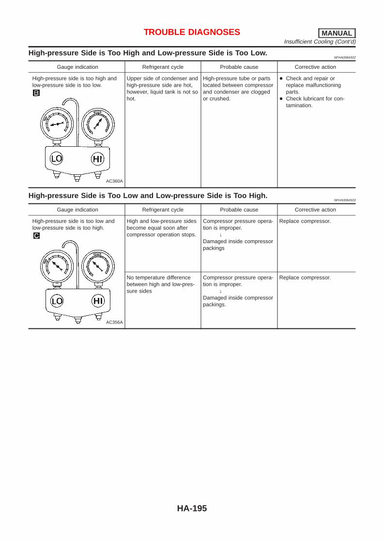
High-pressure Side is Too High and Low-pressure Side is Too Low.NFHA0084S02
Gauge indication Refrigerant cycle Probable cause Corrective action
High-pressure side is too high andlow-pressure side is too low.
AC360A
Upper side of condenser andhigh-pressure side are hot,however, liquid tank is not sohot.
High-pressure tube or partslocated between compressorand condenser are cloggedor crushed.
+ Check and repair orreplace malfunctioningparts.
+ Check lubricant for con-tamination.
High-pressure Side is Too Low and Low-pressure Side is Too High.NFHA0084S03
Gauge indication Refrigerant cycle Probable cause Corrective action
High-pressure side is too low andlow-pressure side is too high.
AC356A
High and low-pressure sidesbecome equal soon aftercompressor operation stops.
Compressor pressure opera-tion is improper.
↓Damaged inside compressorpackings
Replace compressor.
No temperature differencebetween high and low-pres-sure sides
Compressor pressure opera-tion is improper.
↓Damaged inside compressorpackings.
Replace compressor.
TROUBLE DIAGNOSES MANUALInsufficient Cooling (Cont’d)
HA-195

Both High- and Low-pressure Sides are Too Low.NFHA0084S04
Gauge indication Refrigerant cycle Probable cause Corrective action
Both high- and low-pressure sidesare too low.
AC353A
+ There is a big temperaturedifference betweenreceiver drier outlet andinlet. Outlet temperature isextremely low.
+ Liquid tank inlet andexpansion valve arefrosted.
Compressor dischargecapacity does not change.(Compressor stroke is set atmaximum.)
+ Replace liquid tank ordesiccant assembly.
+ Check lubricant for con-tamination.
+ Temperature of expansionvalve inlet is extremelylow as compared withareas near liquid tank.
+ Expansion valve inlet maybe frosted.
+ Temperature differenceoccurs somewhere inhigh- pressure side
High-pressure pipe locatedbetween receiver drier andexpansion valve is clogged.
+ Check and repair malfunc-tioning parts.
+ Check lubricant for con-tamination.
+ Expansion valve and liquidtank are warm or only coolwhen touched.
Low refrigerant charge↓
Leaking fittings or compo-nents
Check refrigerant for leaks.Refer to “Checking Refriger-ant Leaks”, HA-214.
There is a big temperaturedifference between expan-sion valve inlet and outletwhile the valve itself isfrosted.
Expansion valve closes alittle compared with thespecification.
↓1. Improper expansion valve
adjustment2. Malfunctioning thermal
valve3. Outlet and inlet may be
clogged.
+ Remove foreign particlesby using compressed air.
+ Check lubricant for con-tamination.
An area of the low-pressurepipe is colder than areasnear the evaporator outlet.
Low-pressure pipe is cloggedor crushed.
+ Check and repair malfunc-tioning parts.
+ Check lubricant for con-tamination.
Air flow volume is notenough or is too low.
Evaporator is frozen.↓
Compressor dischargecapacity does not change.(Compressor stroke is set atmaximum length.)
Replace compressor.
TROUBLE DIAGNOSES MANUALInsufficient Cooling (Cont’d)
HA-196

Low-pressure Side Sometimes Becomes Negative.NFHA0084S05
Gauge indication Refrigerant cycle Probable cause Corrective action
Low-pressure side sometimesbecomes negative.
AC354A
+ Air conditioning systemdoes not function anddoes not cyclically coolthe compartment air.
+ The system constantlyfunctions for a certainperiod of time after com-pressor is stopped andrestarted.
Refrigerant does not dis-charge cyclically.
↓Moisture is frozen at expan-sion valve outlet and inlet.
↓Water is mixed with refriger-ant.
+ Drain water from refriger-ant or replace refrigerant.
+ Replace liquid tank ordesiccant assembly.
Low-pressure Side Becomes Negative.NFHA0084S06
Gauge indication Refrigerant cycle Probable cause Corrective action
Low-pressure side becomes nega-tive.
AC362A
Liquid tank or front/rear sideof expansion valve’s pipe isfrosted or dewed.
High-pressure side is closedand refrigerant does not flow.
↓Expansion valve or liquidtank is frosted.
Leave the system at restuntil no frost is present. Startit again to check whether ornot the problem is caused bywater or foreign particles.+ If water is the cause, ini-
tially cooling is okay. Thenthe water freezes causinga blockage. Drain waterfrom refrigerant or replacerefrigerant.
+ If due to foreign particles,remove expansion valveand remove particles withdry and compressed air(not shop air).
+ If either of the abovemethods cannot correctthe problem, replaceexpansion valve.
+ Replace liquid tank ordesiccant assembly.
+ Check lubricant for con-tamination.
TROUBLE DIAGNOSES MANUALInsufficient Cooling (Cont’d)
HA-197

Insufficient HeatingTROUBLE DIAGNOSIS PROCEDURE FOR INSUFFICIENT HEATING
=NFHA0140
Symptom:+ Insufficient Heating.Inspection Flow
RHA444HA
*1: HA-169*2: HA-161*3: HA-160
*4: MA-16*5: LC-11
*6: LC-16*7: MA-16
TROUBLE DIAGNOSES MANUALInsufficient Heating
HA-198

NoiseTROUBLE DIAGNOSIS PROCEDURE FOR NOISE
=NFHA0080
Symptom:+ NoiseInspection Flow
SHA336F
*1: HA-207*2: HA-207
*3: HA-202 *4: MA-15
TROUBLE DIAGNOSES MANUALNoise
HA-199

HFC-134a (R-134a) Service ProcedureNFHA0094
SETTING OF SERVICE TOOLS AND EQUIPMENTNFHA0094S01
Discharging RefrigerantNFHA0094S0101
WARNING:Avoid breathing A/C refrigerant and lubricant vapor or mist. Exposure may irritate eyes, nose andthroat. Use only approved recovery/recycling equipment to discharge HFC-134a (R-134a) refrigerant.If accidental system discharge occurs, ventilate work area before resuming service. Additional healthand safety information may be obtained from refrigerant and lubricant manufacturers.
SHA539DE
Evacuating System and Charging RefrigerantNFHA0094S0102
SHA540DC
SERVICE PROCEDURE MANUALHFC-134a (R-134a) Service Procedure
HA-200

SHA386F
*1: HA-202*2: HA-214
*3: HA-215 *4: HA-191
SERVICE PROCEDURE MANUALHFC-134a (R-134a) Service Procedure (Cont’d)
HA-201

Maintenance of Lubricant Quantity inCompressor
NFHA0095
The lubricant in the compressor circulates through the system withthe refrigerant. Add lubricant to compressor when replacing anycomponent or after a large gas leakage occurred. It is important tomaintain the specified amount. If lubricant quantity is not main-tained properly, the following malfunctions may result:+ Lack of lubricant: May lead to a seized compressor+ Excessive lubricant: Inadequate cooling (thermal exchange
interference)
LUBRICANTNFHA0095S01
Name: Nissan A/C System Oil Type SPart number: KLH00-PAGS0
CHECKING AND ADJUSTINGNFHA0095S02
Adjust the lubricant quantity according to the test group shownbelow.
1 LUBRICANT RETURN OPERATION
Can lubricant return operation be performed?+ A/C system works properly.+ There is no evidence of a large amount of lubricant leakage.
Yes or No
Yes © GO TO 2.
No © GO TO 3.
2 PERFORM LUBRICANT RETURN OPERATION, PROCEEDING AS FOLLOWS
1. Start engine, and set the following conditions:Test conditionEngine speed: Idling to 1,200 rpmA/C or AUTO switch: ONBlower speed: Max. positionTemp. control: Optional [Set so that intake air temperature is 25 to 30°C (77 to 86°F).]
2. Next item is for V-6 compressor. Connect the manifold gauge, and check that the high pressure side pressureis 588 kPa (5.9 bar, 6 kg/cm 2, 85 psi) or higher.If less than the reference level, attach a cover to the front face of the condenser to raise the pressure.
3. Perform lubricant return operation for about 10 minutes.4. Stop engine.CAUTION:If excessive lubricant leakage is noted, do not perform the lubricant return operation.
© GO TO 3.
3 CHECK COMPRESSOR
Should the compressor be replaced?
Yes or No
Yes © GO TO HA-203.
No © GO TO 4.
SERVICE PROCEDURE MANUALMaintenance of Lubricant Quantity in Compressor
HA-202

4 CHECK ANY PART
Is there any part to be replaced? (Evaporator, condenser, liquid tank or in case there is evidence of a large amount oflubricant leakage.)
Yes or No
Yes © GO TO HA-203.
No © Carry out the A/C performance test.
Lubricant Adjusting Procedure for ComponentsReplacement Except Compressor
NFHA0095S0201
After replacing any of the following major components, add thecorrect amount of lubricant to the system.Amount of lubricant to be added
Part replaced
Lubricant to be added tosystem
RemarksAmount of lubricant
m! (Imp fl oz)
Evaporator 75 (2.6) —
Condenser 75 (2.6) —
Liquid tank 5 (0.2)Add if compressor is not
replaced. *1
In case of refrigerantleak
30 (1.1) Large leak
— Small leak *2
*1: If compressor is replaced, addition of lubricant is included in the table.*2: If refrigerant leak is small, no addition of lubricant is needed.
Lubricant Adjustment Procedure for CompressorReplacement
NFHA0095S0202
1. Discharge refrigerant into the refrigerant recovery/recyclingequipment. Measure lubricant discharged into the recovery/recycling equipment.
2. Remove the drain plug of the “old” (removed) compressor.Drain the lubricant into a graduated container and record theamount of drained lubricant.
3. Remove the drain plug and drain the lubricant from the “new”compressor into a separate, clean container.
4. Measure an amount of new lubricant installed equal to amountdrained from “old” compressor. Add this lubricant to “new” com-pressor through the suction port opening.
5. Measure an amount of new lubricant equal to the amountrecovered during discharging. Add this lubricant to “new” com-pressor through the suction port opening.
6. Torque the drain plug.V-6 compressor:
18 - 19 N·m (1.8 - 1.9 kg-m, 13 - 14 ft-lb)7. If the liquid tank also needs to be replaced, add an additional
5 m! (0.2 Imp fl oz) of lubricant at this time.Do not add this 5 m! (0.2 Imp fl oz) of lubricant if only replac-ing the compressor.
SERVICE PROCEDURE MANUALMaintenance of Lubricant Quantity in Compressor (Cont’d)
HA-203

RHA065DI
SERVICE PROCEDURE MANUALMaintenance of Lubricant Quantity in Compressor (Cont’d)
HA-204

CompressorREMOVAL AND INSTALLATION
NFHA0096
RHA463E
Compressor ClutchOVERHAUL
NFHA0097
RHA122F
SERVICE PROCEDURE MANUALCompressor
HA-205

RHA136E
REMOVALNFHA0098
+ When removing center bolt, hold clutch disc with clutch discwrench.
RHA399FA
RHA124FA
+ Remove the clutch disc using the clutch disc puller.Insert the holder’s three pins into the holes in the clutch disc.Rotate the holder clockwise to hook it onto the plate. Then,tighten the center bolt to remove the clutch disc.After removing the clutch disc, remove the shims from eitherthe drive shaft or the clutch disc.
RHA138E
+ Remove the snap ring using external snap ring pliers.
RHA139E
+ Pulley removalPosition the center pulley puller on the end of the drive shaft,and remove the pulley assembly using any commercially avail-able pulley puller.To prevent the pulley groove from being deformed, thepuller claws should be positioned onto the edge of thepulley assembly.
SERVICE PROCEDURE MANUALCompressor Clutch (Cont’d)
HA-206
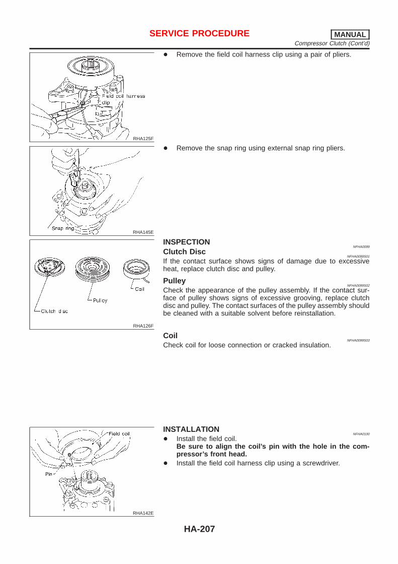
RHA125F
+ Remove the field coil harness clip using a pair of pliers.
RHA145E
+ Remove the snap ring using external snap ring pliers.
RHA126F
INSPECTIONNFHA0099
Clutch DiscNFHA0099S01
If the contact surface shows signs of damage due to excessiveheat, replace clutch disc and pulley.
PulleyNFHA0099S02
Check the appearance of the pulley assembly. If the contact sur-face of pulley shows signs of excessive grooving, replace clutchdisc and pulley. The contact surfaces of the pulley assembly shouldbe cleaned with a suitable solvent before reinstallation.
CoilNFHA0099S03
Check coil for loose connection or cracked insulation.
RHA142E
INSTALLATIONNFHA0100
+ Install the field coil.Be sure to align the coil’s pin with the hole in the com-pressor’s front head.
+ Install the field coil harness clip using a screwdriver.
SERVICE PROCEDURE MANUALCompressor Clutch (Cont’d)
HA-207

RHA143E
+ Install the pulley assembly using the installer and a handpress, and then install the snap ring using snap ring pliers.
RHA127F
+ Install the clutch disc on the drive shaft, together with theoriginal shim(s). Press the clutch disc down by hand.
RHA086E
+ Using the holder to prevent clutch disc rotation, tighten the boltto 14 N·m (1.4 kg-m, 10 ft-lb) torque.After tightening the bolt, check that the pulley rotatessmoothly.
RHA087E
+ Check clearance around the entire periphery of clutch disc.Disc-to-pulley clearance:
0.3 - 0.6 mm (0.012 - 0.024 in)If the specified clearance is not obtained, replace adjustingspacer and readjust.
Break-in OperationNFHA0100S01
When replacing compressor clutch assembly, always carry out thebreak-in operation. This is done by engaging and disengaging theclutch about thirty times. Break-in operation raises the level oftransmitted torque.
SERVICE PROCEDURE MANUALCompressor Clutch (Cont’d)
HA-208
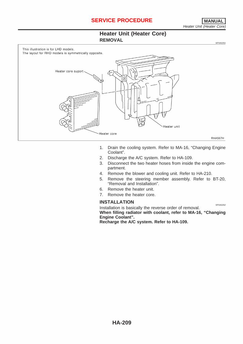
Heater Unit (Heater Core)REMOVAL
NFHA0261
RHA567H
1. Drain the cooling system. Refer to MA-16, “Changing EngineCoolant”.
2. Discharge the A/C system. Refer to HA-109.3. Disconnect the two heater hoses from inside the engine com-
partment.4. Remove the blower and cooling unit. Refer to HA-210.5. Remove the steering member assembly. Refer to BT-20,
“Removal and Installation”.6. Remove the heater unit.7. Remove the heater core.
INSTALLATIONNFHA0262
Installation is basically the reverse order of removal.When filling radiator with coolant, refer to MA-16, “ChangingEngine Coolant”.Recharge the A/C system. Refer to HA-109.
SERVICE PROCEDURE MANUALHeater Unit (Heater Core)
HA-209

Blower and Cooling Unit (A/C Evaporator)REMOVAL
NFHA0263
RHA422HA
RHA421H
1. Discharge the A/C system. Refer to HA-200.2. Disconnect the two refrigerant lines from the engine compart-
ment.Cap the A/C lines to prevent moisture from entering the sys-tem.
3. Remove the glove box and mating trim. Refer to BT-20,“Removal and Installation”.
4. Disconnect the thermal amp. connector.5. Disconnect the fan resistor and blower motor connector.6. Remove the blower and cooling unit.7. Separate the blower and cooling unit case, and remove the
evaporator.
INSTALLATIONNFHA0264
Installation is basically the reverse order of removal.Recharge the A/C system. Refer to HA-200.
SERVICE PROCEDURE MANUALBlower and Cooling Unit (A/C Evaporator)
HA-210

RHA984HA
Desiccant AssemblyREMOVAL
NFHA0279
1. Discharge the A/C system. Refer to HA-200.2. Disconnect the two refrigerant lines from condenser. Cap the
A/C lines to prevent moisture from entering the system.3. Remove the radiator top mount.4. Remove the condenser assembly.5. Remove the snap ring, cap, O-ring, filter and desiccant
assembly.
INSTALLATIONNFHA0280
Install in reverse order of removal.Recharge the A/C system. Refer to HA-200.CAUTION:Always replace used snap ring, cap, O-ring, filter and desic-cant assembly.
SERVICE PROCEDURE MANUALDesiccant Assembly
HA-211
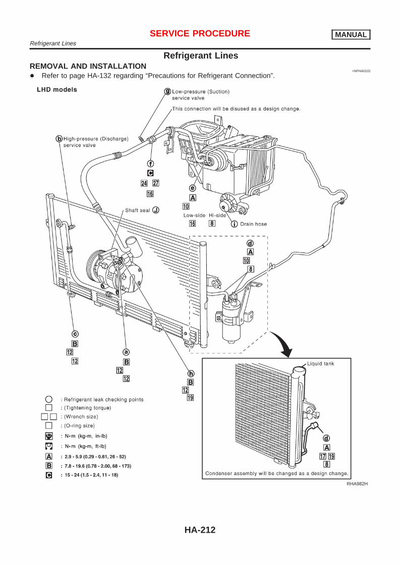
Refrigerant LinesREMOVAL AND INSTALLATION
=NFHA0101
+ Refer to page HA-132 regarding “Precautions for Refrigerant Connection”.
RHA982H
SERVICE PROCEDURE MANUALRefrigerant Lines
HA-212

RHA983H
+ Refer to HA-132, “Precautions for Refrigerant Connection”.
SERVICE PROCEDURE MANUALRefrigerant Lines (Cont’d)
HA-213

CHECKING REFRIGERANT LEAKS=NFHA0102
Preliminary CheckNFHA0102S01
+ Perform a visual inspection of all refrigeration parts, fittings,hoses, and components for signs of A/C lubricant leakage,damage and corrosion. Take note of the areas with A/C lubri-cant leakage to allow extra time in these areas with electronicleak detector.
+ If dye is observed, confirm the leak with an electronic refriger-ant leak detector. It is possible a prior leak was repaired andnot properly cleaned.
+ When searching for leaks, do not stop when one leak is foundbut continue to check for additional leaks at all system compo-nents and connections.
+ When searching for refrigerant leaks using an electronic leakdetector, move the probe along the suspected leak area at 1to 2 inches per second and no further than 1/4 inch from thecomponent.
NOTE:Moving the electronic leak detector probe slower and closer tothe suspected leak area will improve the chances of finding aleak.
SHA705EB
Precautions for Handling Leak DetectorNFHA0102S02
When performing a refrigerant leak check, use an A/C leak detec-tor or equivalent. Ensure that the instrument is calibrated and setproperly per the operating instructions.The leak detector is a delicate device. In order to use the leakdetector properly, read the operating instructions and perform anyspecified maintenance.Other gases in the work area or substances on the A/Ccomponents, for example, anti-freeze, windshield washerfluid, solvents and lubricants, may falsely trigger the leakdetector. Make sure the surfaces to be checked are clean.Clean with a dry cloth or blow off with shop air. Do not allowthe sensor tip of the detector to contact with any substance.This can also cause false readings and may damage the detec-tor.
SHA707EA
1. Position probe approximately 5 mm (3/16 in) away from pointto be checked.
SERVICE PROCEDURE MANUALRefrigerant Lines (Cont’d)
HA-214

SHA706E
2. When testing, circle each fitting completely with probe.
SHA708EA
3. Move probe along component approximately 25 to 50 mm (1to 2 in)/sec.
Checking ProcedureNFHA0102S03
To prevent inaccurate or false readings, make sure there is norefrigerant vapor, shop chemicals, or cigarette smoke in thevicinity of the vehicle. Perform the leak test in calm area (lowair/wind movement) so that the leaking refrigerant is not dis-persed.1. Turn engine off.2. Connect a suitable A/C manifold gauge set to the A/C service
ports.3. Check if the A/C refrigerant pressure is at least 345 kPa (3.45
bar, 3.52 kg/cm2, 50 psi) above 16°C (61°F). If less thanspecification, recover/evacuate and recharge the system withthe specified amount of refrigerant.
NOTE:At temperatures below 16°C (61°F), leaks may not be detectedsince the system may not reach 345 kPa (3.45 bar, 3.52 kg/cm2,50 psi).4. Conduct the leak test from the high side (compressor dis-
charge a to evaporator inlet e) to the low side (evaporator dis-charge e to shaft seal j). Refer to HA-212. Perform a leakcheck for the following areas carefully. Clean the componentto be checked and move the leak detector probe completelyaround the connection/component.
+ CompressorCheck the fitting of high and low pressure hoses, relief valveand shaft seal.
+ Liquid tankCheck the refrigerant pressure sensor, tube fitting, weld seamsand the fusible plug mount.
+ Service valvesCheck all around the service valves. Ensure service valve capsare secured on the service valves (to prevent leaks).
SERVICE PROCEDURE MANUALRefrigerant Lines (Cont’d)
HA-215

NOTE:After removing A/C manifold gauge set from service valves, wipeany residue from valves to prevent any false readings by leakdetector.+ Cooling unit (Evaporator)
With engine OFF, turn blower fan on “High” for at least 15seconds to dissipate any refrigerant trace in the cooling unit.Wait a minimum of 10 minutes accumulation time (refer to themanufacturer’s recommended procedure for actual wait time)before inserting the leak detector probe into the drain hose.Keep the probe inserted for at least ten seconds. Use cautionnot to contaminate the ptobe tip with water or dirt that may bein the drain hose.
5. If a leak detector detects a leak, verify at least once by blow-ing compressed air into area of suspected leak, then repeatcheck as outlined above.
6. Do not stop when one leak is found. Continue to check foradditional leaks at all system components.If no leaks are found, perform steps 7 - 10.
7. Start engine.8. Set the heater A/C control as follows:1) A/C switch ON.2) Face mode3) Recirculation switch ON4) Max cold temperature5) Fan speed high9. Run engine at 1,500 rpm for at least 2 minutes.10. Turn engine off and perform leak check again following steps
4 through 6 above.
SHA839E
Refrigerant leaks should be checked immediately afterstopping the engine. Begin with the leak detector at thecompressor. The pressure on the high pressure side willgradually drop after refrigerant circulation stops and pres-sure on the low pressure side will gradually rise, as shownin the graph. Some leaks are more easily detected whenpressure is high.
11. Discharge A/C system using approved refrigerant recoveryequipment. Repair the leaking fitting or component as neces-sary.
12. Evacuate and recharge A/C system and perform the leak testto confirm no refrigerant leaks.
13. Conduct A/C performance test to ensure system worksproperly.
SERVICE PROCEDURE MANUALRefrigerant Lines (Cont’d)
HA-216

Fluorescent Dye Leak DetectorNFHA0281
PRECAUTIONS FOR FLUORESCENT DYE LEAKDETECTION
NFHA0281S01
+ The fluorescent dye leak detector is not a replacement for anelectronic refrigerant leak detector. The fluorescent dye leakdetector should be used in conjunction with an electronicrefrigerant leak detector to pinpoint refrigerant leaks.
+ For your safety and your customer’s satisfaction, read and fol-low all manufacturer’s operating instructions and precautionsprior to performing the work.
+ Refer to “Precautions for Leak Detection Dye”, HA-131.
CHECKING SYSTEM FOR LEAKS USING THEFLUORESCENT LEAK DETECTOR
NFHA0281S02
1. Check A/C system for leaks using the UV lamp and safetyglasses (J-42220) in a low sunlight area (area without windowspreferable). Illuminate all components, fittings and lines. Thedye will appear as a bright green/yellow area at the point ofleakage. Fluorescent dye observed at the evaporator drainopening indicates an evaporator core assembly (tubes, core orTXV) leak.
2. If the suspected area is difficult to see, use an adjustable mir-ror or wipe the area with a clean shop rag or cloth, then checkthe cloth with the UV lamp for dye residue.
3. Confirm any suspected leaks with an approved electronicrefrigerant leak detector.
4. After the leak is repaired, remove any residual dye using dyecleaner (J-43872) to prevent future misdiagnosis.
5. Perform a system performance check and verify the leak repairwith an approved electronic refrigerant leak detector.
DYE INJECTIONNFHA0281S03
(This procedure is only necessary when re-charging the system orwhen the compressor has seized and was replaced.)Refer to “Precautions for Leak Detection Dye”, HA-131.1. Check A/C system static (at rest) pressure. Pressure must be
at least 345 kPa (3.45 bar, 3.52 kg/cm2, 50 psi).2. Pour one bottle (1/4 ounce / 7.4 cc) of the A/C refrigerant dye
into the injector (J-41459).3. Connect the injector tool to the A/C LOW PRESSURE side
service fitting.4. Start engine and switch A/C ON.5. With the A/C operating (compressor running), inject one bottle
(1/4 ounce / 7.4 cc) of fluorescent dye through the low-pres-sure service valve using dye injector (J-41459) (refer to themanufacturer’s operating instructions).
6. With the engine still running, disconnect the injector tool fromthe service fitting.
CAUTION:Be careful not to allow dye to spray or drip when disconnect-ing the injector from the system.NOTE:If repairing the A/C system or replacing a component, pour thedye directly into the open system connection and proceedwith the service procedures.7. Operate the A/C system for a minimum of 20 minutes to mix
SERVICE PROCEDURE MANUALFluorescent Dye Leak Detector
HA-217
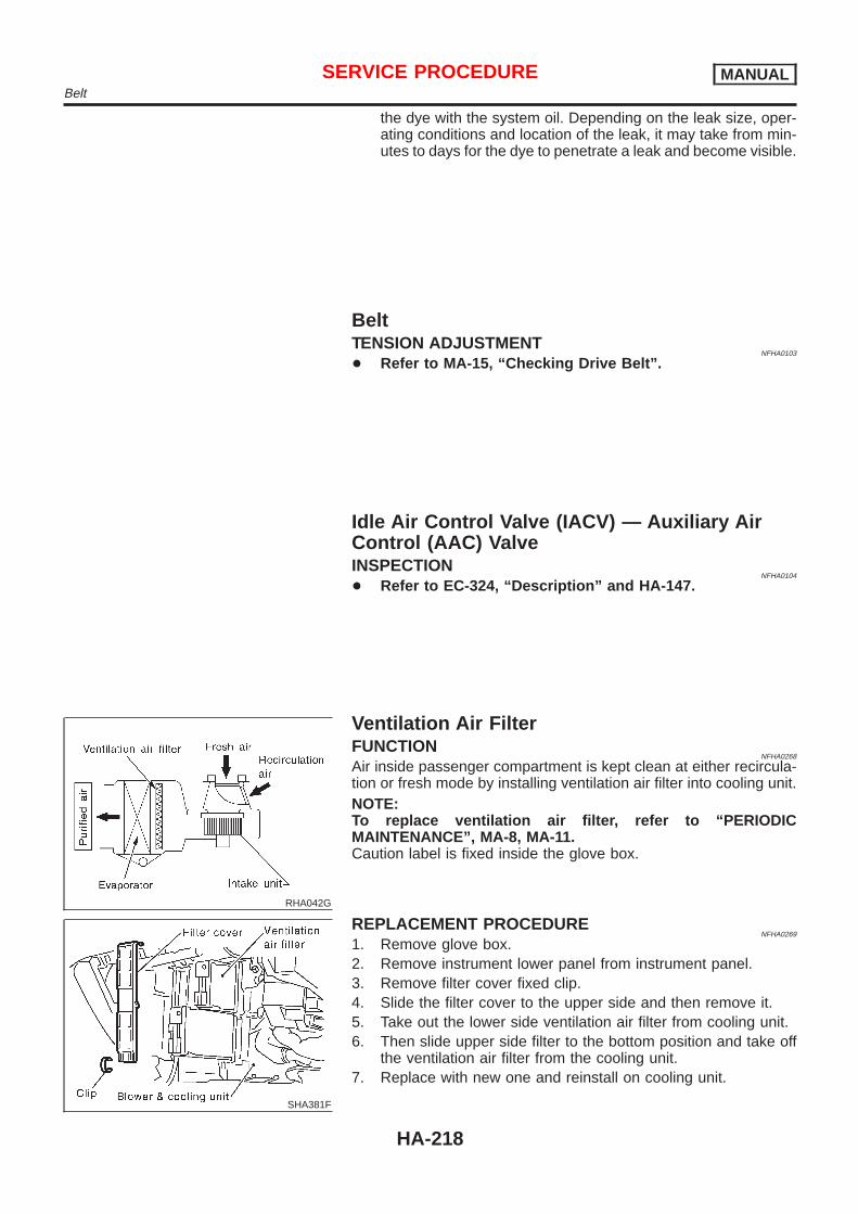
the dye with the system oil. Depending on the leak size, oper-ating conditions and location of the leak, it may take from min-utes to days for the dye to penetrate a leak and become visible.
BeltTENSION ADJUSTMENT
NFHA0103
+ Refer to MA-15, “Checking Drive Belt”.
Idle Air Control Valve (IACV) — Auxiliary AirControl (AAC) ValveINSPECTION
NFHA0104
+ Refer to EC-324, “Description” and HA-147.
RHA042G
Ventilation Air FilterFUNCTION
NFHA0268
Air inside passenger compartment is kept clean at either recircula-tion or fresh mode by installing ventilation air filter into cooling unit.NOTE:To replace ventilation air filter, refer to “PERIODICMAINTENANCE”, MA-8, MA-11.Caution label is fixed inside the glove box.
SHA381F
REPLACEMENT PROCEDURENFHA0269
1. Remove glove box.2. Remove instrument lower panel from instrument panel.3. Remove filter cover fixed clip.4. Slide the filter cover to the upper side and then remove it.5. Take out the lower side ventilation air filter from cooling unit.6. Then slide upper side filter to the bottom position and take off
the ventilation air filter from the cooling unit.7. Replace with new one and reinstall on cooling unit.
SERVICE PROCEDURE MANUALBelt
HA-218

8. Reinstall filter cover, clip, instrument lower panel and glovebox.
SERVICE PROCEDURE MANUALVentilation Air Filter (Cont’d)
HA-219

ManualCOMPRESSOR
NFHA0105
Model CALSONIC make V-6
Type V-6 variable displacement
Displacementcm3 (cu in)/rev.
Max. 184 (11.228)
Min. 14.5 (0.885)
Cylinder bore x strokemm (in)
37 (1.46) x [2.3 - 28.6 (0.091 - 1.126)]
Direction of rotation Clockwise (viewed from drive end)
Drive belt Poly V
LUBRICANTNFHA0106
Model CALSONIC make V-6
Name Nissan A/C System Oil Type S
Part number* KLH00-PAGS0
Capacitym! (Imp fl oz)
Total in system 200 (7.0) [180 (6.3)]
Compressor (Service part) charging amount 200 (7.0) [180 (6.3)]
*: Always check with Parts Department for the latest parts information.[ ]: Capacity will be changed as a design change.
REFRIGERANTNFHA0107
Type HFC-134a (R-134a)
Capacitykg (lb)
0.60 - 0.70 (1.32 - 1.54)
ENGINE IDLING SPEED (WHEN A/C IS ON)NFHA0108
+ Refer to EC-559, “Description”.
BELT TENSIONNFHA0109
+ Refer to MA-15, “Checking Drive Belt”.
SERVICE DATA AND SPECIFICATIONS (SDS) MANUALManual
HA-220


![Index [] · Section 01050 Project Record Documents 01050_Jan04_2005.pdf ... Section 06010 Concrete Sidewalk, ... Section 11002 Transparent Noise Barriers 11002_Apr03_2018.pdf](https://img.pdfslide.us/doc/110x75/5b5ff4ea7f8b9aa2388b52e6/index-section-01050-project-record-documents-01050jan042005pdf-section.jpg)