Embed Size (px)
Citation preview
Section IV
CLUTCHSERVICE BULLETIN REFERENCE
NUMBER DATE SUBJECT CHANGES
106—CLUTCH CHRYSLER SHOP MANUAL
Section IV
CLUTCH
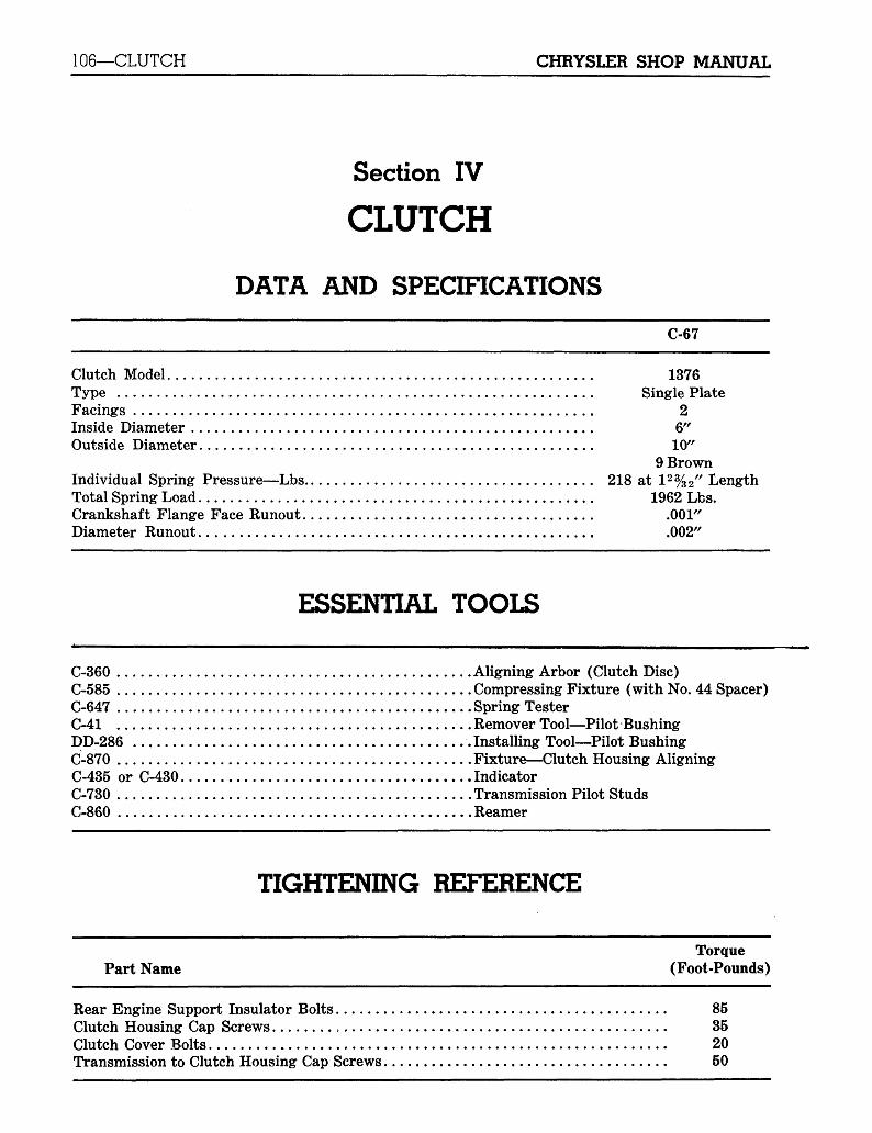
DATA AND SPECIFICATIONS
C-67
Clutch Model 1376Type Single PlateFacings 2Inside Diameter 6"Outside Diameter 10"
9 BrownIndividual Spring Pressure—Lbs 218 at 12%2" LengthTotal Spring Load 1962 Lbs.Crankshaft Flange Face Runout .001"Diameter Runout .002"
ESSENTIAL TOOLS
C-360 Aligning Arbor (Clutch Disc)C-585 Compressing Fixture (with No. 44 Spacer)C-647 Spring TesterC-41 Remover Tool—Pilot BushingDD-286 .Installing Tool—Pilot BushingC-870 Fixture—Clutch Housing AligningC-435 or C-430 IndicatorC-730 Transmission Pilot StudsC-860 Reamer
TIGHTENING REFERENCE
TorquePart Name (Foot-Pounds)
Rear Engine Support Insulator Bolts 85Clutch Housing Cap Screws , 35Clutch Cover Bolts 20Transmission to Clutch Housing Cap Screws 50
CHRYSLER SHOP MANUAL CLUTCH—107
Section IV
CLUTCH(C-67 ONLY)
1. GENERAL INFORMATION
The clutch is of the single dry disc type, with noadjustment for wear being provided in the clutchitself. An individual adjustment is provided forlocating each lever in the manufacturing processand should never be disturbed, unless the clutchis to be removed from the car for repair or over-hauling.
The only adjustment required while the clutchis in the car, is linkage adjustment to obtain thecorrect amount of clutch pedal free play. Clutchpedal free play is the movement of the pedalbefore the clutch starts to engage or disengage.
Linkage adjustment is required to restore pedalfree play when it has been reduced by normalwear of the clutch.
The only service maintenance required is regu-lar periodic lubrication of the clutch (linkage)torque shaft pivot bearings.
CAUTION
It is very important, when rebuilding or install-ing a clutch, that the correct clutch disc, pressureplate and springs be installed. Serious vibration,noise or grabbing, chattery clutch will result.(Note the total spring pressure and color ofsprings.)
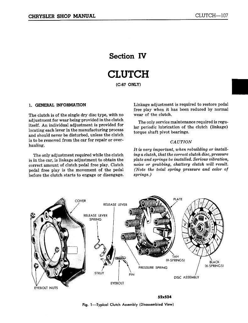
COVERRELEASE LEVER
RELEASE LEVERSPRING
ACK(6-SPRINGS)
STRUTDISC ASSEMBLY
EYEBOLT
EYEBOLT NUTS
52x524
Fig. 1—Typical Clutch Assembly (Disassembled View)
108—CLUTCH CHRYSLER SHOP MANUAL
SERVICE PROCEDURES
2. REMOVAL AND INSTALLATION OF CLUTCHa. Removal
Improper operation or excessive wear may im-pair the clutch function to the point which maynecessitate its removal and overhaul.
The clutch can be removed only after thetransmission has been removed. To remove theclutch, proceed as follows:
(1) Remove the transmission.
(2) Remove the clutch housing pan.
(3) Pull out the clutch release bearing andsleeve.
(4) Mark the clutch cover and flywheel, asshown in Figure 2. Remove the bolts thathold the clutch cover to the flywheel. Looseneach bolt a few turns (in succession) untilcover is free. The clutch disc and pressureplate assembly can now be removed fromthe clutch housing.
b. Installation
When installing the clutch, observe the followingprecautions:
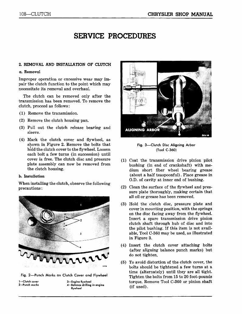
Fig. 2—Punch Marks on Clutch Cover and Flywheel
1— Clutch cover2—Punch marks
3—Engine flywheel4—Balance drilling in engine
flywheel
Fig. 3—Clutch Disc Aligning Arbor
(Tool C-360)
(1) Coat the transmission drive pinion pilotbushing (in end of crankshaft) with me-dium short fiber wheel bearing grease(about a half teaspoonf ul). Place grease inO.D. of cavity at inner end of bushing.
(2) Clean the surface of the flywheel and pres-sure plate thoroughly, making certain thatall oil or grease has been removed.
(3) Hold the clutch disc, pressure plate andcover in mounting position, with the springson the disc facing away from the flywheel.Insert a spare transmission drive pinionclutch shaft through hub of disc and intothe pilot bushing. If this item is not avail-able, Tool C-360 may be used, as illustratedin Figure 3.
(4) Insert the clutch cover attaching bolts(after aligning balance punch marks) butdo not tighten.
(5) To avoid distortion of the clutch cover, thebolts should be tightened a few turns at atime (alternately) until they are all tight.Tighten the bolts from 15 to 20 foot-poundstorque. Remove Tool C-360 or pinion shaft(if used).
CHRYSLER SHOP MANUAL CLUTCH—109
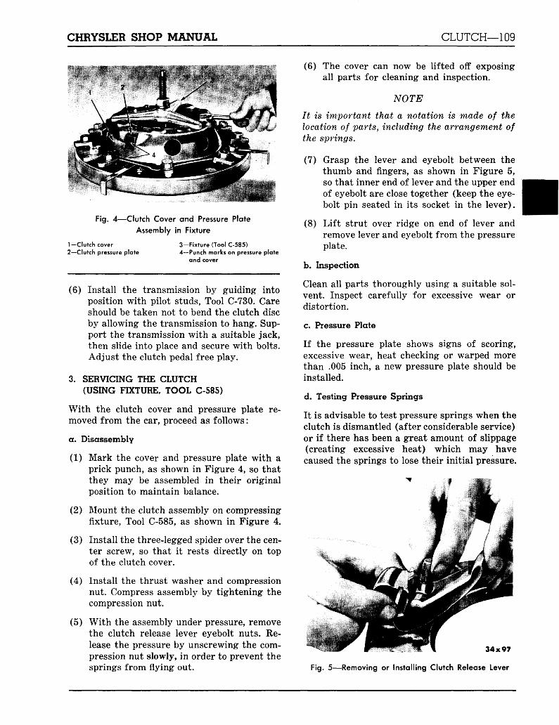
Fig. 4—Clutch Cover and Pressure PlateAssembly in Fixture
1 —Clutch cover2—Clutch pressure plate
3-Fixture (Tool C-585)4—Punch marks on pressure plate
and cover
(6) Install the transmission by guiding intoposition with pilot studs, Tool C-730. Careshould be taken not to bend the clutch discby allowing the transmission to hang. Sup-port the transmission with a suitable jack,then slide into place and secure with bolts.Adjust the clutch pedal free play.
3. SERVICING THE CLUTCH(USING FIXTURE, TOOL C-585)
With the clutch cover and pressure plate re-moved from the car, proceed as follows:
a. Disassembly
(1) Mark the cover and pressure plate with aprick punch, as shown in Figure 4, so thatthey may be assembled in their originalposition to maintain balance.
(2) Mount the clutch assembly on compressingfixture, Tool C-585, as shown in Figure 4.
(3) Install the three-legged spider over the cen-ter screw, so that it rests directly on topof the clutch cover.
(4) Install the thrust washer and compressionnut. Compress assembly by tightening thecompression nut.
(5) With the assembly under pressure, removethe clutch release lever eyebolt nuts. Re-lease the pressure by unscrewing the com-pression nut slowly, in order to prevent thesprings from flying out.
(6) The cover can now be lifted off exposingall parts for cleaning and inspection.
NOTE
It is important that a notation is made of thelocation of parts, including the arrangement ofthe springs.
(7) Grasp the lever and eyebolt between thethumb and fingers, as shown in Figure 5,so that inner end of lever and the upper endof eyebolt are close together (keep the eye-bolt pin seated in its socket in the lever).
(8) Lift strut over ridge on end of lever andremove lever and eyebolt from the pressureplate.
b. Inspection
Clean all parts thoroughly using a suitable sol-vent. Inspect carefully for excessive wear ordistortion.
c. Pressure Plate
If the pressure plate shows signs of scoring,excessive wear, heat checking or warped morethan .005 inch, a new pressure plate should beinstalled.
d. Testing Pressure Springs
It is advisable to test pressure springs when theclutch is dismantled (after considerable service)or if there has been a great amount of slippage(creating excessive heat) which may havecaused the springs to lose their initial pressure.
\
34x97
Fig. 5—Removing or Installing Clutch Release Lever
110—CLUTCH CHRYSLER SHOP MANUAL
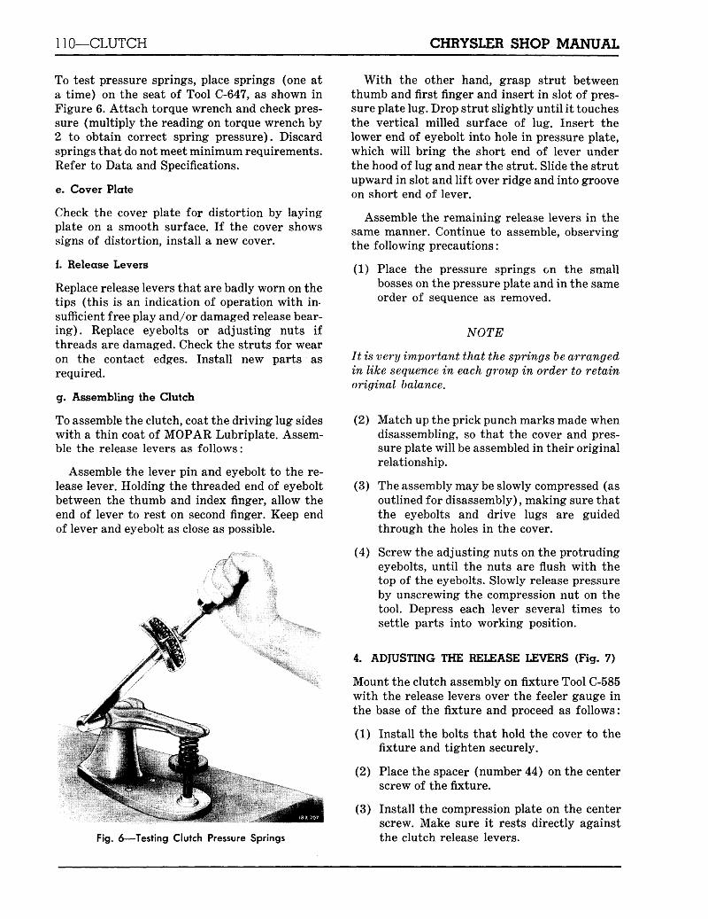
To test pressure springs, place springs (one ata time) on the seat of Tool C-647, as shown inFigure 6. Attach torque wrench and check pres-sure (multiply the reading on torque wrench by2 to obtain correct spring pressure). Discardsprings that do not meet minimum requirements.Refer to Data and Specifications.
e. Cover Plate
Check the cover plate for distortion by layingplate on a smooth surface. If the cover showssigns of distortion, install a new cover.
f. Release Levers
Replace release levers that are badly worn on thetips (this is an indication of operation with in-sufficient free play and/or damaged release bear-ing). Replace eyebolts or adjusting nuts ifthreads are damaged. Check the struts for wearon the contact edges. Install new parts asrequired.
g. Assembling the Clutch
To assemble the clutch, coat the driving lug sideswith a thin coat of MOPAR Lubriplate. Assem-ble the release levers as follows:
Assemble the lever pin and eyebolt to the re-lease lever. Holding the threaded end of eyeboltbetween the thumb and index finger, allow theend of lever to rest on second finger. Keep endof lever and eyebolt as close as possible.
Fig. 6—Testing Clutch Pressure Springs
With the other hand, grasp strut betweenthumb and first finger and insert in slot of pres-sure plate lug. Drop strut slightly until it touchesthe vertical milled surface of lug. Insert thelower end of eyebolt into hole in pressure plate,which will bring the short end of lever underthe hood of lug and near the strut. Slide the strutupward in slot and lift over ridge and into grooveon short end of lever.
Assemble the remaining release levers in thesame manner. Continue to assemble, observingthe following precautions:
(1) Place the pressure springs on the smallbosses on the pressure plate and in the sameorder of sequence as removed.
NOTE
It is very important that the springs be arrangedin like sequence in each group in order to retainoriginal balance.
(2) Match up the prick punch marks made whendisassembling, so that the cover and pres-sure plate will be assembled in their originalrelationship.
(3) The assembly may be slowly compressed (asoutlined for disassembly), making sure thatthe eyebolts and drive lugs are guidedthrough the holes in the cover.
(4) Screw the adjusting nuts on the protrudingeyebolts, until the nuts are flush with thetop of the eyebolts. Slowly release pressureby unscrewing the compression nut on thetool. Depress each lever several times tosettle parts into working position.
4. ADJUSTING THE RELEASE LEVERS (Fig. 7)
Mount the clutch assembly on fixture Tool C-585with the release levers over the feeler gauge inthe base of the fixture and proceed as follows:
(1) Install the bolts that hold the cover to thefixture and tighten securely.
(2) Place the spacer (number 44) on the centerscrew of the fixture.
(3) Install the compression plate on the centerscrew. Make sure it rests directly againstthe clutch release levers.
CHRYSLER SHOP MANUAL CLUTCH—111
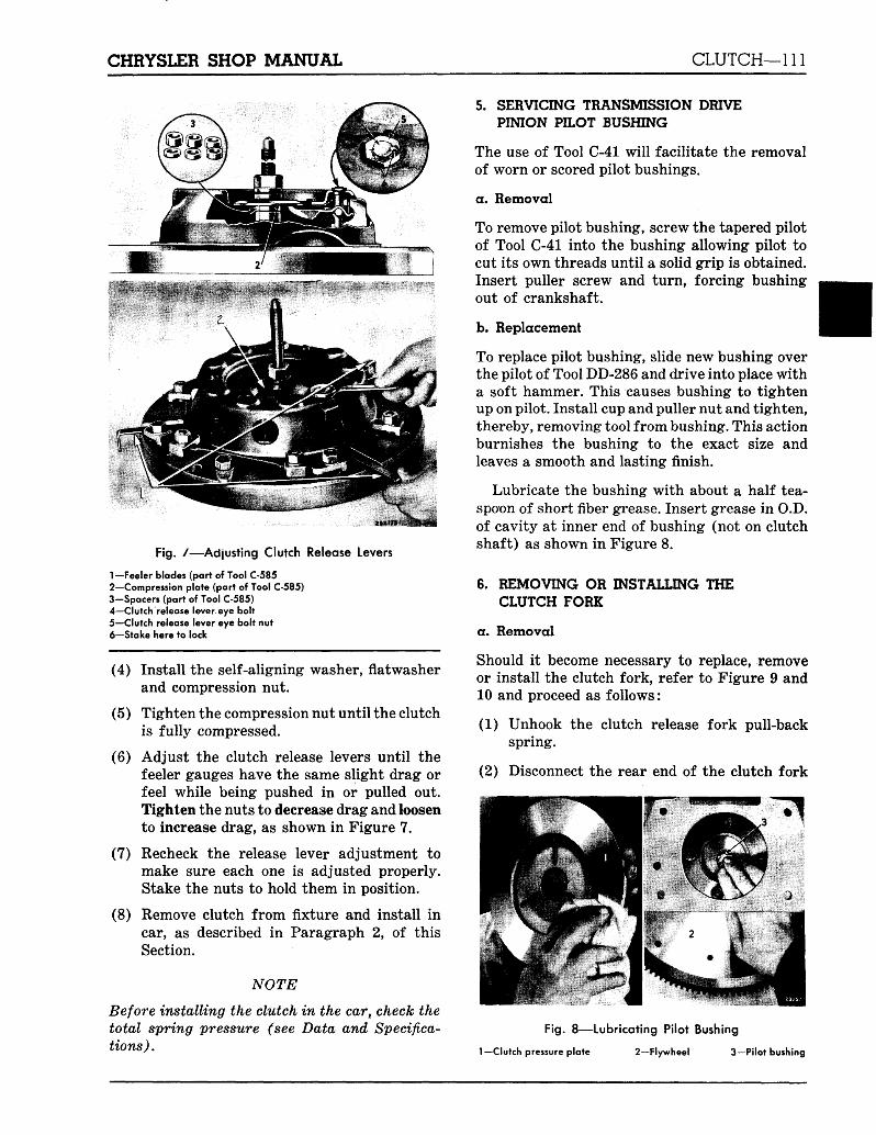
Fig. /—Adjusting Clutch Release Levers
1-Feeler blades (part of Tool C-5852—Compression plate (part of Tool C-585)3-Spacers (part of Tool C-585)4—Clutch release lever eye bolt5—Clutch release lever eye bolt nut6-Stake here to lock
(4) Install the self-aligning washer, flatwasherand compression nut.
(5) Tighten the compression nut until the clutchis fully compressed.
(6) Adjust the clutch release levers until thefeeler gauges have the same slight drag orfeel while being pushed in or pulled out.Tighten the nuts to decrease drag and loosento increase drag, as shown in Figure 7.
(7) Recheck the release lever adjustment tomake sure each one is adjusted properly.Stake the nuts to hold them in position.
(8) Remove clutch from fixture and install incar, as described in Paragraph 2, of thisSection.
NOTE
Before installing the clutch in the car, check thetotal spring pressure (see Data and Specifica-tions) .
5. SERVICING TRANSMISSION DRIVEPINION PILOT BUSHING
The use of Tool C-41 will facilitate the removalof worn or scored pilot bushings.
a. Removal
To remove pilot bushing, screw the tapered pilotof Tool C-41 into the bushing allowing pilot tocut its own threads until a solid grip is obtained.Insert puller screw and turn, forcing bushingout of crankshaft.
b. Replacement
To replace pilot bushing, slide new bushing overthe pilot of Tool DD-286 and drive into place witha soft hammer. This causes bushing to tightenup on pilot. Install cup and puller nut and tighten,thereby, removing tool from bushing. This actionburnishes the bushing to the exact size andleaves a smooth and lasting finish.
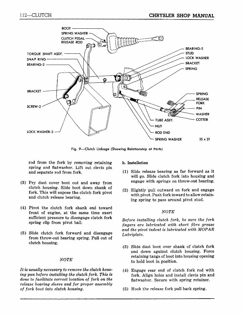
Lubricate the bushing with about a half tea-spoon of short fiber grease. Insert grease in O.D.of cavity at inner end of bushing (not on clutchshaft) as shown in Figure 8.
6. REMOVING OR INSTALLING THECLUTCH FORK
a. Removal
Should it become necessary to replace, removeor install the clutch fork, refer to Figure 9 and10 and proceed as follows:
(1) Unhook the clutch release fork pull-backspring.
(2) Disconnect the rear end of the clutch fork
Fig. 8—Lubricating Pilot Bushing
Hutch pressure plate 2—Flywheel 3—Pilot bushing
112—CLUTCH CHRYSLER SHOP MANUAL
BOOT
SPRING WASHER
CLUTCH PEDALRELEASE ROD
TORQUE SHAFT ASSY.
SNAP RING
BEARING-2
BRACKET
SCREW-3
LOCK WASHER-3
BEARING-2STUDLOCK WASHER
BRACKET
SPRING
NUT
ROD END
SPRING WASHER
SPRING
RELEASEFORK
PIN
WASHER
COTTER
55x21
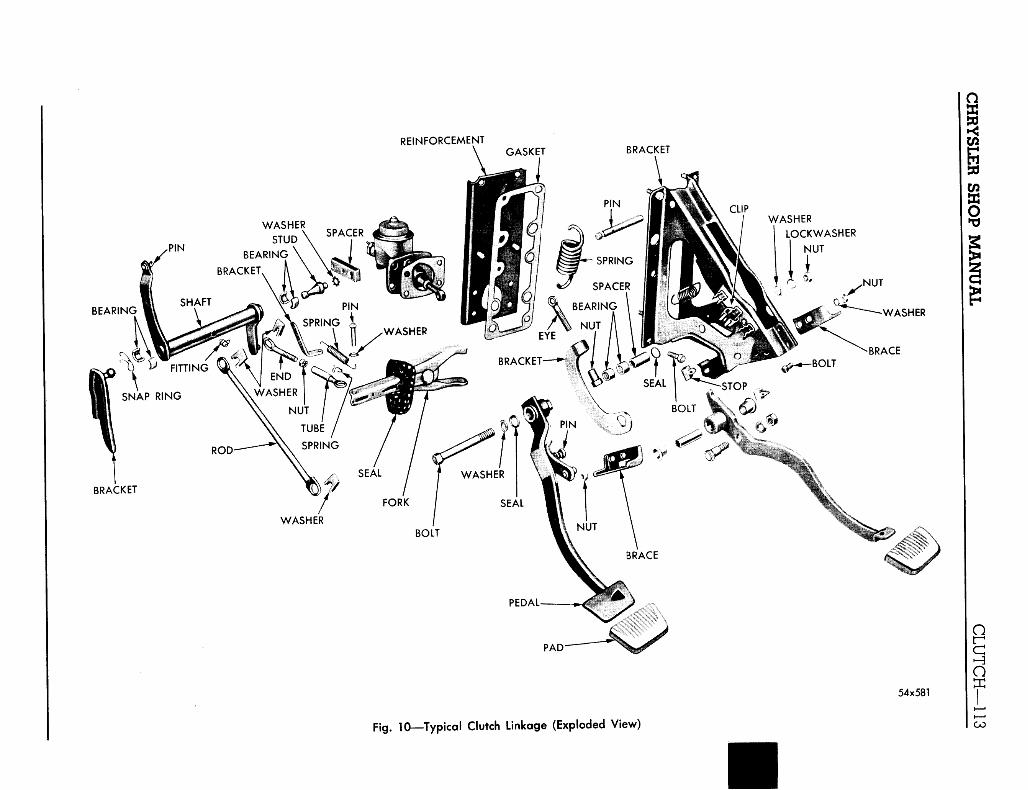
Fig. 9—Clutch Linkage (Showing Relationship ot Parts)
rod from the fork by removing retainingspring and flatwasher. Lift out clevis pinand separate rod from fork.
(3) Pry dust cover boot out and away fromclutch housing. Slide boot down shank offork. This will expose the clutch fork pivotand clutch release bearing.
(4) Pivot the clutch fork shank end towardfront of engine, at the same time exertsufficient pressure to disengage clutch forkspring clip from pivot ball.
(5) Slide clutch fork forward and disengagefrom throw-out bearing spring. Pull out ofclutch housing.
NOTE
It is usually necessary to remove the clutch hous-ing pan before installing the clutch fork. This isdone to facilitate correct location of fork on therelease bearing sleeve and for proper assemblyof fork boot into clutch housing.
b. Installation
(1) Slide release bearing as far forward as itwill go. Slide clutch fork into housing andengage with springs on throw-out bearing.
(2) Slightly pull outward on fork and engagewith pivot. Push fork inward to allow retain-ing spring to pass around pivot stud.
NOTE
Before installing clutch fork, be sure the forkfingers are lubricated with short fibre greaseand the pivot indent is lubricated with MOPARLubriplate.
(3) Slide dust boot over shank of clutch forkand down against clutch housing. Forceretaining tangs of boot into housing openingto hold boot in position.
(4) Engage rear end of clutch fork rod withfork. Align holes and install clevis pin andflatwasher. Secure with spring retainer.
(5) Hook the release fork pull back spring.
REINFORCEMENTGASKET BRACKET
WASHER
LOCKWASHER
NUT
BEARING
FORK / SEAL
BOLT
BRACKET
PAD-
54x581
Fig. 10—Typical Clutch Linkage (Exploded View)
114—CLUTCH CHRYSLER SHOP MANUAL
WINDSHIELD
EYE BOLT-
ADJUSTING NUTr
DASH PANEL-
INSTRUMENT PANEL
STEERING COLUMN
CLUTCH OVER-CENTER SPRING
PEDAL MOUNTING BRACKET
PEDAL RETURNRUBBER STOP
CLUTCHPEDAL H STEERING
COLUMN
ACCELERATOR PEDAL-W'v j
PEDAL LOCATION
PEDAL TRAVEL
ACCELERATORPEDAL
TORQUE SHAFT
CLUTCH FORK PULL BACK SPRING
CLUTCH RELEASEFORK ROD
CLUTCH RELEASE FORK FRAME
54x620
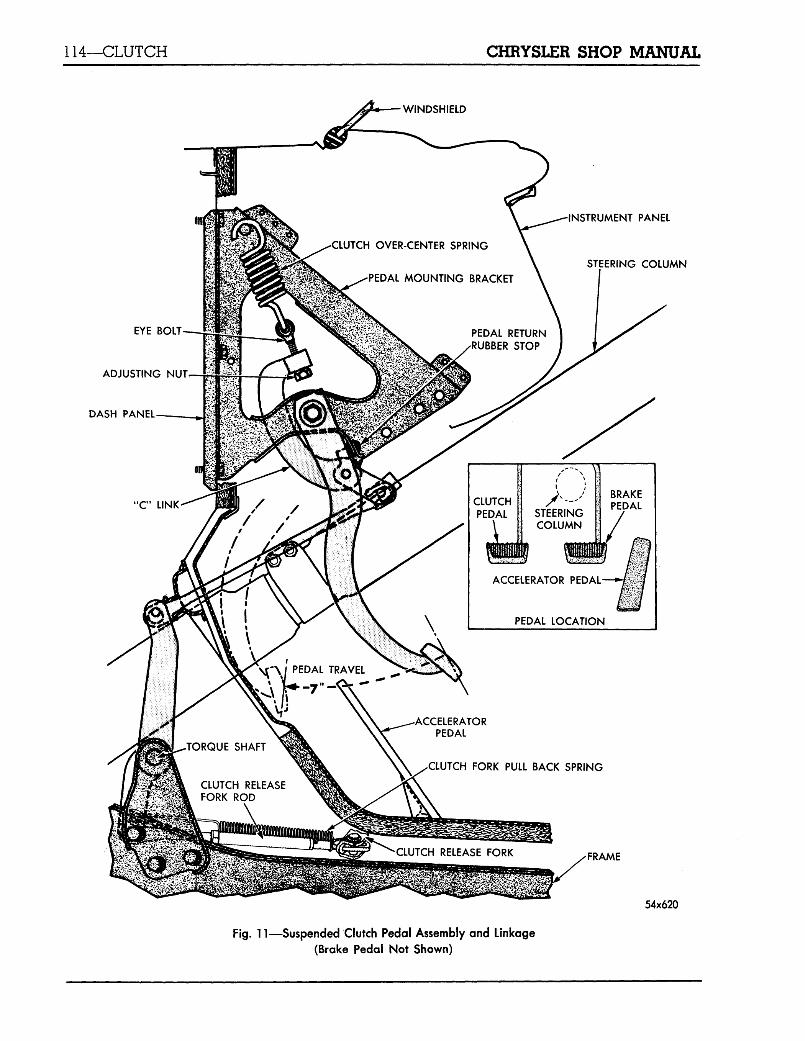
Fig. 11—Suspended Clutch Pedal Assembly and Linkage
(Brake Pedal Not Shown)
CHRYSLER SHOP MANUAL CLUTCH—115
7. REPLACING CLUTCH TORQUE SHAFTPIVOT BUSHINGS
a. Disassembly
To install new torque shaft bushings, refer toFigures 9 and 10 and proceed as follows:
(1) Unhook the clutch release fork pull-backspring from bracket and fork.
(2) Remove the spring retainer that holds theclutch fork rod to the torque shaft. Disen-gage rod from shaft. Swing rod out of way.
(3) Remove the spring retainer holding thepedal rod to the torque shaft. Disengagepedal rod from torque shaft lever pin.
(4) Remove the bolts that hold the torque shaftbracket to the frame. (These bolts arelocated up under the front fender behindsplash shield).
(5) Remove the retaining spring that holds thepivot, bracket and bushings to the torqueshaft. Exert sufficient pressure to forcebushings out of torque shaft.
(6) Pull torque shaft away from pivot on clutchhousing. This forces bushings out of torqueshaft. Remove torque shaft from under car.
Clean all parts in a suitable solvent and blowdry with compressed air. Inspect the pivot ballsand bushings for signs of scoring or excessivewear. Install new parts as required.
b. Assembly
To assemble the torque shaft, refer to Figures9 and 10 and proceed as follows:
(1) Lubricate the pivot bushings with a suitablechassis grease, and slide over the pivot ballattached to the clutch housing. Slide endof torque shaft over the bushings and downinto position.
(2) Place the two remaining bushings on thepivot ball mounted on the bracket. Slide thefree end of the torque shaft over the bush-ings and down into position. Install theretaining spring.
(3) Slide the pivot bracket against the frameside rail and install bolts and lockwashers.Tighten securely.
(4) Engage the clutch pedal rod with the torqueshaft lever pin and install spring clip.
(5) Slide the clutch fork rod over pin on lowerlever of torque shaft and install spring clip.
(6) Slide one end of the clutch release fork pullback spring in the hole in fork shank, andthe other end into bracket on housing.
(7) After new bushings have been installed,lubricate thoroughly. Check the clutch pedalfor free play (approximately 1" at the pedalpad or %6" free movement at the outer endof the clutch fork).
8. ADJUSTING THE OVER-CENTER SPRING
The position of the over-center spring is con-trolled by an adjusting nut and threaded eye,shown in Figure 11.
The upper end of the "C" link is attached bythe threaded eyebolt to the over-center spring.The lower end of the "C" link is attached by apivot to the clutch pedal. The over-center springis attached at the top end by a pin at the uppercorner of the pedal mounting bracket.
To adjust the over-center spring, refer toFigure 11, and proceed as follows:
(1) Remove spring clip that holds the clutchpedal rod to the clutch pedal.
(2) Back off the over-center spring adjustingnut until free of "C" link.
(3) With the pedal at 7 inches travel positionuse the fingers, run adjusting nut back upuntil it just contacts the "C" link.
(4) Turn adjusting nut against "C" link 7 fullturns. No more!
(5) Install clutch pedal rod and secure withspring clip.
This adjustment should give from 12 to 15pounds pressure on clutch pedal when pedal isheld down 1 inch from fully released position.
9. CLUTCH PEDAL ADJUSTMENT(FREE MOVEMENT)
Adjust the clutch fork rod "in" or "out" asrequired to secure %6 inch free play of the clutchrelease fork outer end. This will provide the 1inch free pedal movement at the pedal pad witha total of 7 inches full pedal travel.
116—CLUTCH CHRYSLER SHOP MANUAL
The upper end of the clutch pedal pivots inthe lower end of the mounting bracket, on needlebearings. These bearings require no periodiclubrication, however, they should be lubricatedwith wheel bearing grease if the pedal is removedfor any repair function.
10. CLUTCH HOUSING ALIGNMENT
When performing adjustments or repairs thatinvolve removing the clutch housing, it will benecessary to align the face of the housing paral-lel with that of the block, when assembling.
To correctly align the clutch housing, proceedas follows:
(1) Inspect the housing face where it contactsthe cylinder block, for particles of dirt orburrs. Remove burrs with a file and cleanboth surfaces thoroughly. Install clutchhousing. Tighten clutch housing to blockbolts just snug enough so the housing canbe shifted if necessary by tapping with amallet.
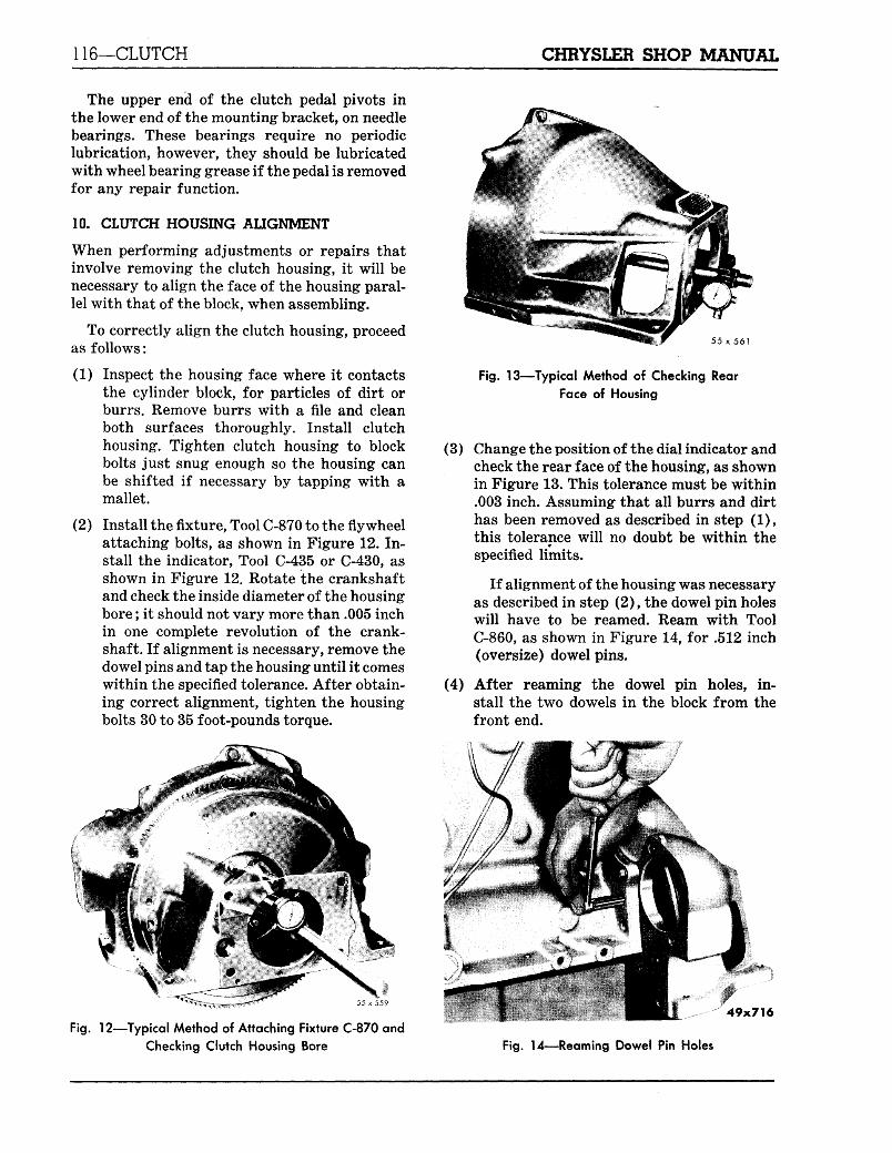
(2) Install the fixture, Tool C-870 to the flywheelattaching bolts, as shown in Figure 12. In-stall the indicator, Tool C-435 or C-430, asshown in Figure 12. Rotate the crankshaftand check the inside diameter of the housingbore; it should not vary more than .005 inchin one complete revolution of the crank-shaft. If alignment is necessary, remove thedowel pins and tap the housing until it comeswithin the specified tolerance. After obtain-ing correct alignment, tighten the housingbolts 30 to 35 foot-pounds torque.
55 x561
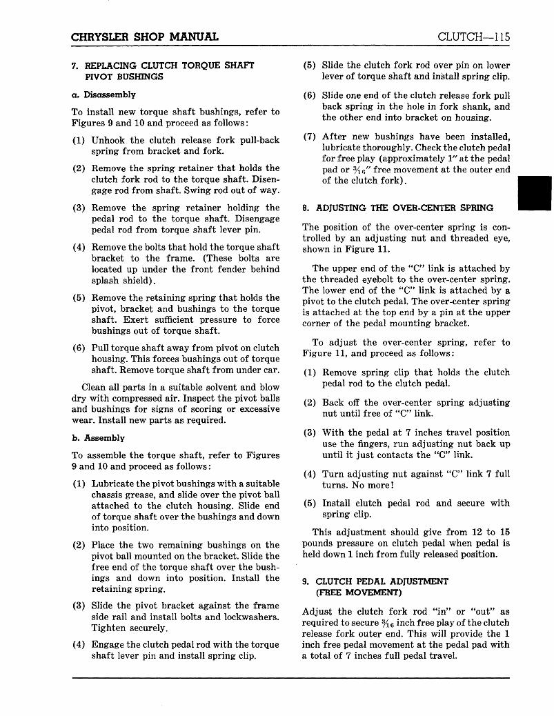
Fig. 13—Typical Method of Checking Rear
Face of Housing
(3) Change the position of the dial indicator andcheck the rear face of the housing, as shownin Figure 13. This tolerance must be within.003 inch. Assuming that all burrs and dirthas been removed as described in step (1),this tolerance will no doubt be within thespecified limits.
If alignment of the housing was necessaryas described in step (2), the dowel pin holeswill have to be reamed. Ream with ToolC-860, as shown in Figure 14, for .512 inch(oversize) dowel pins.
(4) After reaming the dowel pin holes, in-stall the two dowels in the block from thefront end.
Fig. 12—Typical Method of Attaching Fixture C-870 and
Checking Clutch Housing Bore
49x716
Fig. 14—Reaming Dowel Pin Holes
CHRYSLER SHOP MANUAL CLUTCH—117
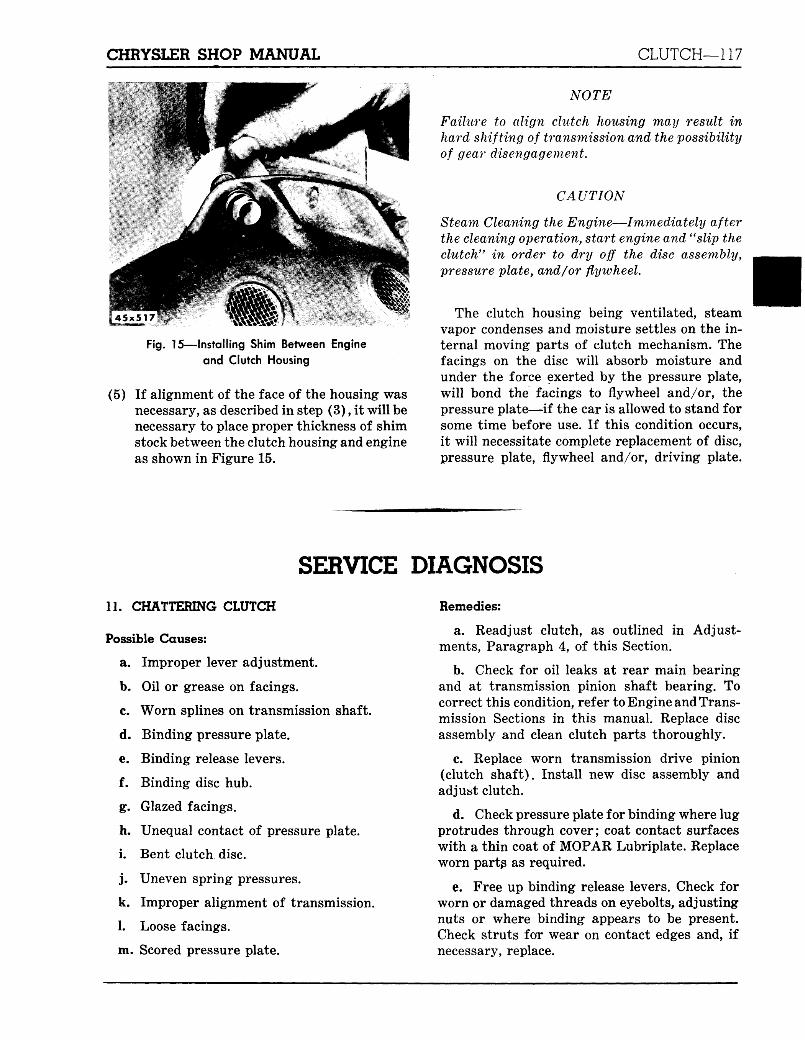
Fig. 15—Installing Shim Between Engine
and Clutch Housing
(5) If alignment of the face of the housing wasnecessary, as described in step (3), it will benecessary to place proper thickness of shimstock between the clutch housing and engineas shown in Figure 15.
NOTE
Failure to align clutch housing may result inhard shifting of transmission and the possibilityof gear disengagement.
CAUTION
Steam Cleaning the Engine—Immediately afterthe cleaning operation, start engine and "slip theclutch*' in order to dry off the disc assembly,pressure plate, and/or flywheel.
The clutch housing being ventilated, steamvapor condenses and moisture settles on the in-ternal moving parts of clutch mechanism. Thefacings on the disc will absorb moisture andunder the force exerted by the pressure plate,will bond the facings to flywheel and/or, thepressure plate—if the car is allowed to stand forsome time before use. If this condition occurs,it will necessitate complete replacement of disc,pressure plate, flywheel and/or, driving plate.
SERVICE DIAGNOSIS
11. CHATTERING CLUTCH
Possible Causes:
a. Improper lever adjustment.
b. Oil or grease on facings.
c. Worn splines on transmission shaft.
d. Binding pressure plate.
e. Binding release levers.
f. Binding disc hub.
g. Glazed facings.
h. Unequal contact of pressure plate.
i. Bent clutch disc.
j . Uneven spring pressures.
k. Improper alignment of transmission.
1. Loose facings.
m. Scored pressure plate.
Remedies:
a. Readjust clutch, as outlined in Adjust-ments, Paragraph 4, of this Section.
b. Check for oil leaks at rear main bearingand at transmission pinion shaft bearing. Tocorrect this condition, refer to Engine and Trans-mission Sections in this manual. Replace discassembly and clean clutch parts thoroughly.
c. Replace worn transmission drive pinion(clutch shaft). Install new disc assembly andadjust clutch.
d. Check pressure plate for binding where lugprotrudes through cover; coat contact surfaceswith a thin coat of MOPAR Lubriplate. Replaceworn partg as required.
e. Free up binding release levers. Check forworn or damaged threads on eyebolts, adjustingnuts or where binding appears to be present.Check struts for wear on contact edges and, ifnecessary, replace.
118—CLUTCH CHRYSLER SHOP MANUAL
f. Replace disc assembly and adjust clutch.
g. Replace disc assembly after checking pres-sure plate, flywheel or driving plate for possiblescoring. If parts are badly scored or worn, com-plete replacement is required.
h. Check clearances of release levers, disc forthickness and pressure plate for parallel positionagainst flywheel or driving plate.
i. Replace disc assembly after checking to de-termine cause of distortion. Examine pressureplate for excessive wear or scoring. Replace ifnecessary.
j . Check springs for pressure, as described inTesting Pressure Springs, Paragraph 3 (d), ofthis Section.
k. Check clutch housing alignment. Misalign-ment between transmission and clutch housingmay be caused by chips, dirt, buckled gaskets orburrs. Check to determine cause and correct.
1. Replace disc assembly. Examine pressureplate and flywheel or driving plate for possiblescoring and excessive wear. Replace as required.
m. If pressure plate shows signs of scoring,excessive wear, heat checking, of if warpedmore than .005 inch, plate must be replaced.
12. GRABBING CLUTCH
Possible Causes:
a. Improper lever adjustment.
b. Oil or grease on facings.
c. Worn pressure plate, flywheel or driveplate.
d. Clutch disc hub sticking on pinion (clutch)shaft.
e. Worn or binding release levers.
f. Worn or glazed facings.
g. Broken or weak pressure springs.
h. Incorrect disc facings.
i. Improper alignment of transmission.
j . Worn or deteriorated rubber engine mount-ings,
k. Engine loose in supports.
Possible Causes:
a. Adjust clutch as outlined in Adjustments,Paragraph 4, of this Section.
b. Replace disc assembly. Check for oil leakat rear main bearing. To replace the oil seal,refer to Engine Section.
c. A flywheel or pressure plate, that showssigns of excessive wear, heat or scoring, must bereplaced.
d. Free up disc hubs. Check pinion shaft forexcessive wear or burrs. Check disc assemblyfor distortion and replace if necessary.
e. Release levers that are badly worn on thetips should be replaced. This is an indication ofoperation with insufficient free play or damagedrelease bearing. Worn or damaged threads oneyebolts or adjusting nuts, or where bindingappears to be present (which retards free move-ment) should be corrected. Check struts forwear on contact edges and replace as required.
f. Replace disc assembly. Check pressureplate for excessive wear or scoring. Replaceparts as required.
g. Replace broken or weak springs. To testsprings for pressure, refer to Testing PressureSprings, Paragraph 3 (d) of this Section.
h. Replace disc assembly. Use Factory Engi-neered and Inspected Clutch Disc Assembly.Adjust clutch.
i. Check clutch housing alignment. Misalign-ment between transmission and clutch housingmay be caused by chips, dirt, buckled gasket orburrs. Check to determine cause and correct.
j . Replace worn engine mountings.
k. Check engine mountings for loose bolts.Tighten as required to correct this condition.
13. SUPPING CLUTCH
Possible Causes:
a. Weak or broken pressure springs:
b. Worn facings.
c. Improper clutch adjustments.
d. Oil or grease on facings.
e. Warped disc assembly.
CHRYSLER SHOP MANUAL CLUTCH—119
f. Warped or scored pressure plate.
g. Binding release levers.
h. Improper clutch linkage adjustment.
Remedies:
a. Replace weak or broken springs. To testsprings for pressure, refer to Testing PressureSprings, Paragraph 3 (d) of this Section.
NOTE
It is advisable to replace pressure springs whenclutch is dismantled (after considerable service)or if there has been a great amount of slippage(creating excessive heat), tvhich may havecaused the springs to lose initial tension.
b. Replace disc assembly. Check pressure,plate, flywheel, or clutch driving plate for pos-sible scoring, heat checking or excessive wear.Test pressure springs for loss of pressure.Replace parts as needed.
c. Examine disc assembly for excessive wearor a glazed surface, pressure plate for possiblescoring or distortion. Test springs for pressure.Replace parts as required. Adjust clutch.
d. Replace disc assembly. Check for oil leak atrear main bearing. To replace the oil seal, referto Engine Section.
e. Replace warped or distorted disc assemblyafter examining pressure plate for possibledamage. Test pressure springs for pressure asdescribed in Paragraph 3 (d) of this Section.
f. A pressure plate that is badly scored, heatchecked or warped more than .020 inch, must bereplaced. Test springs for pressure and installnew disc assembly.
g. Free up release levers where binding ap-pears to be present which retards free move-ment. Examine struts for excessive wear on con-tact surfaces. Lubricate all moving parts withMOPAR Lubriplate. Check disc and pressureplate for scoring or heat checking, and testpressure springs for pressure. Replace parts asrequired.
h. Adjust for clutch pedal free play.
14. DRAGGING CLUTCH
Possible Causes:
a. Oil or grease on facings.
b. Incorrect lever adjustment.
c. Incorrect pedal adjustment.
d. Dust or dirt in clutch.
e. Worn or broken facings.
f. Bent clutch disc.
g. Disc hub binding on pinion shaft.
h. Binding pilot bushing.
i. Sticking release bearing sleeve.
j . Warped pressure plate.
k. Improper alignment of transmission.
1. Clutch facings too thick.
Remedies:
a. Replace disc assembly. Check for oil leak atrear main bearing. To replace the oil seal, referto Engine Section.
b. Read j ust levers after checking for possibledamage. Refer to Paragraph 3, of this Section.
c. Readjust pedal as described in Adjust-ments, Paragraph 8 of this Section.
d. Disassemble clutch and clean thoroughly.Examine all parts for excessive wear or scoring.Replace worn or scored parts as required. Atreassembly, coat all moving parts with a thincoat of MOPAR Lubriplate.
e. Replace disc assembly. Inspect pressureplate for excessive wear or scoring. Test pressuresprings for pressure, as described in Paragraph3, (A) of this Section.
f. Replace bent disc assembly after checkingto determine cause of distortion. Replace worn orscored parts.
g. Free up disc assembly. Check pinion shaft(clutch shaft) for burrs or gummed splines.Replace parts as required to correct thiscondition.
h. Replace pinion shaft (clutch shaft) pilotbushing, as outlined in Paragraph 4 of thisSection.
120—CLUTCH CHRYSLER SHOP MANUAL
i. Free up sticking sleeve and examine matingsurfaces for scoring or rough spots. Replaceparts as required to correct this condition.
j . A pressure plate that is warped more than.005 inch must be replaced. Install new discassembly. Adjust clutch.
k. Check clutch housing alignment. Misalign-ment between transmission and clutch may becaused by chips, dirt, buckled gasket, or burrs.Determine cause of condition and correct.
1. When replacing the disc assembly, alwaysuse Factory Engineered and Inspected Parts.
15. SQUEAKING CLUTCH
Possible Causes:
a. Lack of lubrication in release sleeve.
b. Worn release sleeve.
c. Dry pilot bushing.
d. Pilot bushing turning in crankshaft.
e. Worn drive pinion bearing.
f. Improper alignment of transmission.
g. Dry clutch plate drive lugs.
Remedies:
a. Lubricate release sleeve with MOPARLubriplate.
b. Check sleeve land for interference at Oilitepart of release bearing. Replace sleeve if neces-sary.
c. Replace pilot bushing as outlined in Serv-icing Clutch Shaft Pilot Bushing, Paragraph 5of this Section.
d. Replace pilot bushing as indicated above.
e. Replace worn drive pinion bearing afterchecking bearing retainer for cracks and exces-sive wear. Examine pilot bushing and if neces-sary, replace (see c).
f. Check clutch housing alignment. Misalign-ment between transmission and clutch housingmay be caused by chips, dirt, buckled gasket orburrs. Check to determine cause and correct.
16. VIBRATING CLUTCH
Possible Causes:
a. Improper balance of assembly.
b. Improper fitting of pressure plate.
c. Pressure spring off center.
d. Improper clutch alignment.
e. Loose engine mountings.
f. Worn transmission main shaft rear bear-ing.
Remedies:
a. Replace disc assembly and pressure plateto correct this condition.
b. Check clutch cover for distortion whichwould interfere with correct operation of pres-sure plate. Check clutch cover assembly mount-ing bolts for looseness and tighten if necessary.
c. Check springs for alignment on bosses andtest for tension. See Paragraph 3 (d) of thisSection.
d. Replace disc assembly and align with align-ing Tool C-360. Readjust clutch.
e. Tighten engine mounting bolts as required.
f. Replace worn transmission main shaft rearbearing.
17. VIBRATION PERIODS
Possible Causes:
a. Loss of friction lag in clutch disc damperbecause of oil contamination or use of incorrectdisc assembly.
b. Propeller shaft installed with ends re-versed from original assembly.
c. Broken or sagging rear springs.
Remedies:
a. Install new factory engineered clutch discassembly.
b. Reverse assembly of prop, shaft to trans-mission and axle carrier. Or rotate propellerends 180 degrees relative to transmission andaxle flanges.
g. Apply MOPAR Lubriplate to drive lugs. c. Replace rear springs.