Embed Size (px)
Citation preview

Divis ion 3Containments for Transpor tation and Storage of Spent Nuclear Fuel and High Level Radioactive Material and Waste
ASME BPVC. I I I .3-2015
SECTION I I IRules for Construct ion ofNuclear Faci l i ty Components
2015 ASME Boiler andPressure Vessel CodeAn International Code
Copyrighted material licensed to University of Toronto by Thomson Scientific, Inc. (www.techstreet.com). This copy downloaded on 2015-07-14 21:45:42 -0500 by authorized user logan ahlstrom. No further reproduction or distribution is permitted.
IIIRULES FOR CONSTRUCTIONOF NUCLEAR FACILITYCOMPONENTS
Division 3
Containments forTransportation and Storage ofSpent Nuclear Fuel and HighLevel Radioactive Materialand WasteASME Boiler and Pressure Vessel Committeeon Nuclear Power
AN INTERNATIONAL CODE
2015 ASME Boiler &Pressure Vessel Code2015 Edition July 1, 2015
Two Park Avenue • New York, NY • 10016 USA
Copyrighted material licensed to University of Toronto by Thomson Scientific, Inc. (www.techstreet.com). This copy downloaded on 2015-07-14 21:45:42 -0500 by authorized user logan ahlstrom. No further reproduction or distribution is permitted.

Date of Issuance: July 1, 2015
This international code or standard was developed under procedures accredited as meeting the criteria forAmerican National Standards and it is an American National Standard. The Standards Committee that approvedthe code or standard was balanced to assure that individuals from competent and concerned interests havehad an opportunity to participate. The proposed code or standard was made available for public review and com-ment that provides an opportunity for additional public input from industry, academia, regulatory agencies, andthe public-at-large.ASME does not “approve,” “rate,” or “endorse” any item, construction, proprietary device, or activity.ASME does not take any position with respect to the validity of any patent rights asserted in connection with any
items mentioned in this document, and does not undertake to insure anyone utilizing a standard against liabilityfor infringement of any applicable letters patent, nor assume any such liability. Users of a code or standard areexpressly advised that determination of the validity of any such patent rights, and the risk of infringement of suchrights, is entirely their own responsibility.Participation by federal agency representative(s) or person(s) affiliated with industry is not to be interpreted as
government or industry endorsement of this code or standard.ASME accepts responsibility for only those interpretations of this document issued in accordance with the es-
tablished ASME procedures and policies, which precludes the issuance of interpretations by individuals.The endnotes and preamble in this document (if any) are part of this American National Standard.
ASME collective membership mark
Certification Mark
The above ASME symbol is registered in the U.S. Patent Office.
“ASME” is the trademark of The American Society of Mechanical Engineers.
No part of this document may be reproduced in any form, in an electronicretrieval system or otherwise, without the prior written permission of the
publisher.
Library of Congress Catalog Card Number: 56-3934Printed in the United States of America
Adopted by the Council of The American Society of Mechanical Engineers, 1914; latest edition 2015.
The American Society of Mechanical EngineersTwo Park Avenue, New York, NY 10016-5990
Copyright © 2015 byTHE AMERICAN SOCIETY OF MECHANICAL ENGINEERS
All rights reserved
Copyrighted material licensed to University of Toronto by Thomson Scientific, Inc. (www.techstreet.com). This copy downloaded on 2015-07-14 21:45:42 -0500 by authorized user logan ahlstrom. No further reproduction or distribution is permitted.

TABLE OF CONTENTS
List of Sections . . . . . . . . . . . . . . . . . . . . . . . . . . . . . . . . . . . . . . . . . . . . . . . . . . . . . . . . . . . . . . . . . . . . . . . . . . . . . . xiiForeword . . . . . . . . . . . . . . . . . . . . . . . . . . . . . . . . . . . . . . . . . . . . . . . . . . . . . . . . . . . . . . . . . . . . . . . . . . . . . . . . . . . xivStatement of Policy on the Use of the Certification Mark and Code Authorization in Advertising . . . . . . . . . . xviStatement of Policy on the Use of ASME Marking to Identify Manufactured Items . . . . . . . . . . . . . . . . . . . . . . xviSubmittal of Technical Inquiries to the Boiler and Pressure Vessel Standards Committees . . . . . . . . . . . . . . . xviiPersonnel . . . . . . . . . . . . . . . . . . . . . . . . . . . . . . . . . . . . . . . . . . . . . . . . . . . . . . . . . . . . . . . . . . . . . . . . . . . . . . . . . . . xixOrganization of Section III . . . . . . . . . . . . . . . . . . . . . . . . . . . . . . . . . . . . . . . . . . . . . . . . . . . . . . . . . . . . . . . . . . . . . xxxviSummary of Changes . . . . . . . . . . . . . . . . . . . . . . . . . . . . . . . . . . . . . . . . . . . . . . . . . . . . . . . . . . . . . . . . . . . . . . . . . xxxixList of Changes in Record Order Number . . . . . . . . . . . . . . . . . . . . . . . . . . . . . . . . . . . . . . . . . . . . . . . . . . . . . . . . xliiCross-Referencing and Stylistic Changes in the Boiler and Pressure Vessel Code . . . . . . . . . . . . . . . . . . . . . . . xliii
Subsection WA General Requirements . . . . . . . . . . . . . . . . . . . . . . . . . . . . . . . . . . . . . . . . . . . . . . . . . . . 1
Article WA-1000 Scope of Division 3 . . . . . . . . . . . . . . . . . . . . . . . . . . . . . . . . . . . . . . . . . . . . . . . . . . . . . . 1WA-1100 Scope . . . . . . . . . . . . . . . . . . . . . . . . . . . . . . . . . . . . . . . . . . . . . . . . . . . . . . . . . . . . . . . . . . . 1WA-1110 Nature of These Rules and Containments to Which They Are Applicable . . . . . . . . . . 1WA-1120 Definitions . . . . . . . . . . . . . . . . . . . . . . . . . . . . . . . . . . . . . . . . . . . . . . . . . . . . . . . . . . . . . . 1WA-1130 Limits of These Rules . . . . . . . . . . . . . . . . . . . . . . . . . . . . . . . . . . . . . . . . . . . . . . . . . . . . . 1WA-1140 Use of Code Editions, Addenda, and Cases . . . . . . . . . . . . . . . . . . . . . . . . . . . . . . . . . . . . 1WA-1150 Units of Measure . . . . . . . . . . . . . . . . . . . . . . . . . . . . . . . . . . . . . . . . . . . . . . . . . . . . . . . . . 1
WA-1200 General Requirements . . . . . . . . . . . . . . . . . . . . . . . . . . . . . . . . . . . . . . . . . . . . . . . . . . . . 2WA-1210 Valves . . . . . . . . . . . . . . . . . . . . . . . . . . . . . . . . . . . . . . . . . . . . . . . . . . . . . . . . . . . . . . . . . . 2WA-1220 Materials . . . . . . . . . . . . . . . . . . . . . . . . . . . . . . . . . . . . . . . . . . . . . . . . . . . . . . . . . . . . . . . . 2WA-1230 Parts . . . . . . . . . . . . . . . . . . . . . . . . . . . . . . . . . . . . . . . . . . . . . . . . . . . . . . . . . . . . . . . . . . . 2
Article WA-2000 Design Basis for Containments . . . . . . . . . . . . . . . . . . . . . . . . . . . . . . . . . . . . . . . . . . . 3WA-2100 General Requirements . . . . . . . . . . . . . . . . . . . . . . . . . . . . . . . . . . . . . . . . . . . . . . . . . . . . 3WA-2110 Scope . . . . . . . . . . . . . . . . . . . . . . . . . . . . . . . . . . . . . . . . . . . . . . . . . . . . . . . . . . . . . . . . . . . 3WA-2120 Design Basis . . . . . . . . . . . . . . . . . . . . . . . . . . . . . . . . . . . . . . . . . . . . . . . . . . . . . . . . . . . . . 3WA-2130 Special Requirements . . . . . . . . . . . . . . . . . . . . . . . . . . . . . . . . . . . . . . . . . . . . . . . . . . . . . 4
Article WA-3000 Responsibilities and Duties . . . . . . . . . . . . . . . . . . . . . . . . . . . . . . . . . . . . . . . . . . . . . . 5WA-3100 General . . . . . . . . . . . . . . . . . . . . . . . . . . . . . . . . . . . . . . . . . . . . . . . . . . . . . . . . . . . . . . . . . 5WA-3110 Responsibilities Vs. Legal Liabilities . . . . . . . . . . . . . . . . . . . . . . . . . . . . . . . . . . . . . . . . . 5WA-3120 Authorization . . . . . . . . . . . . . . . . . . . . . . . . . . . . . . . . . . . . . . . . . . . . . . . . . . . . . . . . . . . . 5WA-3130 Welding and Subcontracting of Welding . . . . . . . . . . . . . . . . . . . . . . . . . . . . . . . . . . . . . 6
WA-3300 Responsibilities of an N3 Certificate Holder . . . . . . . . . . . . . . . . . . . . . . . . . . . . . . . . . . 6WA-3320 Categories of the N3 Certificate Holder’s Responsibilities . . . . . . . . . . . . . . . . . . . . . . . 6WA-3330 Obtaining a Certificate . . . . . . . . . . . . . . . . . . . . . . . . . . . . . . . . . . . . . . . . . . . . . . . . . . . . 7WA-3340 Compliance With This Division . . . . . . . . . . . . . . . . . . . . . . . . . . . . . . . . . . . . . . . . . . . . . 7WA-3350 Design Documents . . . . . . . . . . . . . . . . . . . . . . . . . . . . . . . . . . . . . . . . . . . . . . . . . . . . . . . . 7WA-3360 Fabrication Specification . . . . . . . . . . . . . . . . . . . . . . . . . . . . . . . . . . . . . . . . . . . . . . . . . . 8WA-3370 Responsibility for Quality Assurance . . . . . . . . . . . . . . . . . . . . . . . . . . . . . . . . . . . . . . . . 9WA-3380 Data Reports . . . . . . . . . . . . . . . . . . . . . . . . . . . . . . . . . . . . . . . . . . . . . . . . . . . . . . . . . . . . 9WA-3390 N3 Certificate Holder’s Responsibility for Records . . . . . . . . . . . . . . . . . . . . . . . . . . . . . 9
WA-3400 Responsibilities of an NPT Certificate Holder . . . . . . . . . . . . . . . . . . . . . . . . . . . . . . . . . 9WA-3420 Categories of an NPT Certificate Holder’s Responsibilities . . . . . . . . . . . . . . . . . . . . . . 9WA-3430 Obtaining a Certificate . . . . . . . . . . . . . . . . . . . . . . . . . . . . . . . . . . . . . . . . . . . . . . . . . . . . 9WA-3440 Compliance With This Division . . . . . . . . . . . . . . . . . . . . . . . . . . . . . . . . . . . . . . . . . . . . . 9WA-3450 Responsibility for Quality Assurance . . . . . . . . . . . . . . . . . . . . . . . . . . . . . . . . . . . . . . . . 9WA-3460 Documentation of Quality Assurance Program . . . . . . . . . . . . . . . . . . . . . . . . . . . . . . . . 10
iii
Copyrighted material licensed to University of Toronto by Thomson Scientific, Inc. (www.techstreet.com). This copy downloaded on 2015-07-14 21:45:42 -0500 by authorized user logan ahlstrom. No further reproduction or distribution is permitted.
WA-3470 Data Report . . . . . . . . . . . . . . . . . . . . . . . . . . . . . . . . . . . . . . . . . . . . . . . . . . . . . . . . . . . . . 10WA-3800 Metallic Material . . . . . . . . . . . . . . . . . . . . . . . . . . . . . . . . . . . . . . . . . . . . . . . . . . . . . . . . . 10
WA-3810 Scope and Applicability . . . . . . . . . . . . . . . . . . . . . . . . . . . . . . . . . . . . . . . . . . . . . . . . . . . 10WA-3820 Material Organizations . . . . . . . . . . . . . . . . . . . . . . . . . . . . . . . . . . . . . . . . . . . . . . . . . . . . 10
Article WA-4000 Quality Assurance . . . . . . . . . . . . . . . . . . . . . . . . . . . . . . . . . . . . . . . . . . . . . . . . . . . . . . . 11WA-4100 Requirements . . . . . . . . . . . . . . . . . . . . . . . . . . . . . . . . . . . . . . . . . . . . . . . . . . . . . . . . . . . . 11
WA-4110 Scope and Applicability . . . . . . . . . . . . . . . . . . . . . . . . . . . . . . . . . . . . . . . . . . . . . . . . . . . 11WA-4120 Definitions . . . . . . . . . . . . . . . . . . . . . . . . . . . . . . . . . . . . . . . . . . . . . . . . . . . . . . . . . . . . . . 11WA-4130 Establishment and Implementation . . . . . . . . . . . . . . . . . . . . . . . . . . . . . . . . . . . . . . . . . 11
Article WA-5000 Authorized Inspection . . . . . . . . . . . . . . . . . . . . . . . . . . . . . . . . . . . . . . . . . . . . . . . . . . . 13WA-5100 Introduction . . . . . . . . . . . . . . . . . . . . . . . . . . . . . . . . . . . . . . . . . . . . . . . . . . . . . . . . . . . . . 13
WA-5110 Applicability . . . . . . . . . . . . . . . . . . . . . . . . . . . . . . . . . . . . . . . . . . . . . . . . . . . . . . . . . . . . . 13WA-5120 Performance of Inspection . . . . . . . . . . . . . . . . . . . . . . . . . . . . . . . . . . . . . . . . . . . . . . . . . 13WA-5130 Access for Inspection Agency Personnel . . . . . . . . . . . . . . . . . . . . . . . . . . . . . . . . . . . . . 13
WA-5200 Duties of Inspector . . . . . . . . . . . . . . . . . . . . . . . . . . . . . . . . . . . . . . . . . . . . . . . . . . . . . . . 13WA-5210 General Inspection Duties . . . . . . . . . . . . . . . . . . . . . . . . . . . . . . . . . . . . . . . . . . . . . . . . . 13WA-5220 Categories of Inspector’s Duties . . . . . . . . . . . . . . . . . . . . . . . . . . . . . . . . . . . . . . . . . . . . 14WA-5230 Scope of Work, Design Specifications, Design Reports, and Fabrication Specifications 14WA-5240 Quality Assurance Programs . . . . . . . . . . . . . . . . . . . . . . . . . . . . . . . . . . . . . . . . . . . . . . . 14WA-5250 Qualification Records . . . . . . . . . . . . . . . . . . . . . . . . . . . . . . . . . . . . . . . . . . . . . . . . . . . . . 14WA-5260 Materials, Parts, and Heat Treatment . . . . . . . . . . . . . . . . . . . . . . . . . . . . . . . . . . . . . . . . 15WA-5270 Examinations and Tests . . . . . . . . . . . . . . . . . . . . . . . . . . . . . . . . . . . . . . . . . . . . . . . . . . . 15WA-5280 Final Tests . . . . . . . . . . . . . . . . . . . . . . . . . . . . . . . . . . . . . . . . . . . . . . . . . . . . . . . . . . . . . . 15WA-5290 Data Reports . . . . . . . . . . . . . . . . . . . . . . . . . . . . . . . . . . . . . . . . . . . . . . . . . . . . . . . . . . . . 15
WA-5300 Responsibilities of the Authorized Inspection Agency . . . . . . . . . . . . . . . . . . . . . . . . . . 15
Article WA-7000 Reference Standards . . . . . . . . . . . . . . . . . . . . . . . . . . . . . . . . . . . . . . . . . . . . . . . . . . . . 16WA-7100 General Requirements . . . . . . . . . . . . . . . . . . . . . . . . . . . . . . . . . . . . . . . . . . . . . . . . . . . . 16
Article WA-8000 Certificates of Authorization, Nameplates, Certification Mark, and Data Reports 18WA-8100 Authorization to Perform Code Activities . . . . . . . . . . . . . . . . . . . . . . . . . . . . . . . . . . . . 18
WA-8110 General . . . . . . . . . . . . . . . . . . . . . . . . . . . . . . . . . . . . . . . . . . . . . . . . . . . . . . . . . . . . . . . . . 18WA-8120 Scope of Authorization . . . . . . . . . . . . . . . . . . . . . . . . . . . . . . . . . . . . . . . . . . . . . . . . . . . . 18WA-8130 Inspection Agreement Required . . . . . . . . . . . . . . . . . . . . . . . . . . . . . . . . . . . . . . . . . . . . 18WA-8140 Quality Assurance Program Requirements . . . . . . . . . . . . . . . . . . . . . . . . . . . . . . . . . . . . 19WA-8150 Application for Authorization . . . . . . . . . . . . . . . . . . . . . . . . . . . . . . . . . . . . . . . . . . . . . . 19WA-8160 Evaluation for Authorization . . . . . . . . . . . . . . . . . . . . . . . . . . . . . . . . . . . . . . . . . . . . . . . 19WA-8170 Issuance of Authorization . . . . . . . . . . . . . . . . . . . . . . . . . . . . . . . . . . . . . . . . . . . . . . . . . . 19WA-8180 Renewal of Authorization . . . . . . . . . . . . . . . . . . . . . . . . . . . . . . . . . . . . . . . . . . . . . . . . . . 19
WA-8200 Nameplates and Stamping With Certification Mark . . . . . . . . . . . . . . . . . . . . . . . . . . . . 19WA-8210 General Requirements . . . . . . . . . . . . . . . . . . . . . . . . . . . . . . . . . . . . . . . . . . . . . . . . . . . . 19WA-8220 Nameplates . . . . . . . . . . . . . . . . . . . . . . . . . . . . . . . . . . . . . . . . . . . . . . . . . . . . . . . . . . . . . 20WA-8230 Nameplates for Certification Mark with NPT Designator Items . . . . . . . . . . . . . . . . . . 20
WA-8300 Certification Mark . . . . . . . . . . . . . . . . . . . . . . . . . . . . . . . . . . . . . . . . . . . . . . . . . . . . . . . . 20WA-8310 General Requirements . . . . . . . . . . . . . . . . . . . . . . . . . . . . . . . . . . . . . . . . . . . . . . . . . . . . 20WA-8330 Removable Items . . . . . . . . . . . . . . . . . . . . . . . . . . . . . . . . . . . . . . . . . . . . . . . . . . . . . . . . . 21
WA-8400 Data Reports . . . . . . . . . . . . . . . . . . . . . . . . . . . . . . . . . . . . . . . . . . . . . . . . . . . . . . . . . . . . 21WA-8410 General Requirements . . . . . . . . . . . . . . . . . . . . . . . . . . . . . . . . . . . . . . . . . . . . . . . . . . . . 21
Article WA-9000 Glossary . . . . . . . . . . . . . . . . . . . . . . . . . . . . . . . . . . . . . . . . . . . . . . . . . . . . . . . . . . . . . . . . 27WA-9100 Introduction . . . . . . . . . . . . . . . . . . . . . . . . . . . . . . . . . . . . . . . . . . . . . . . . . . . . . . . . . . . . . 27WA-9200 Definitions . . . . . . . . . . . . . . . . . . . . . . . . . . . . . . . . . . . . . . . . . . . . . . . . . . . . . . . . . . . . . . 27
Subsection WB Class TC Transportation Containments . . . . . . . . . . . . . . . . . . . . . . . . . . . . . . . . . . . . 29
Article WB-1000 Introduction . . . . . . . . . . . . . . . . . . . . . . . . . . . . . . . . . . . . . . . . . . . . . . . . . . . . . . . . . . . . 29WB-1100 Scope . . . . . . . . . . . . . . . . . . . . . . . . . . . . . . . . . . . . . . . . . . . . . . . . . . . . . . . . . . . . . . . . . . . 29
WB-1120 Rules for Class TC Transportation Containments . . . . . . . . . . . . . . . . . . . . . . . . . . . . . . 29
iv
Copyrighted material licensed to University of Toronto by Thomson Scientific, Inc. (www.techstreet.com). This copy downloaded on 2015-07-14 21:45:42 -0500 by authorized user logan ahlstrom. No further reproduction or distribution is permitted.
WB-1130 Boundaries of Jurisdiction . . . . . . . . . . . . . . . . . . . . . . . . . . . . . . . . . . . . . . . . . . . . . . . . . 29
Article WB-2000 Material . . . . . . . . . . . . . . . . . . . . . . . . . . . . . . . . . . . . . . . . . . . . . . . . . . . . . . . . . . . . . . . . 31WB-2100 General Requirements for Material . . . . . . . . . . . . . . . . . . . . . . . . . . . . . . . . . . . . . . . . . . 31WB-2110 Scope of Principal Terms Employed . . . . . . . . . . . . . . . . . . . . . . . . . . . . . . . . . . . . . . . . . 31WB-2120 Containment Material . . . . . . . . . . . . . . . . . . . . . . . . . . . . . . . . . . . . . . . . . . . . . . . . . . . . . 31WB-2130 Certification of Material . . . . . . . . . . . . . . . . . . . . . . . . . . . . . . . . . . . . . . . . . . . . . . . . . . . 32WB-2140 Welding Material . . . . . . . . . . . . . . . . . . . . . . . . . . . . . . . . . . . . . . . . . . . . . . . . . . . . . . . . . 32WB-2150 Material Identification . . . . . . . . . . . . . . . . . . . . . . . . . . . . . . . . . . . . . . . . . . . . . . . . . . . . 32WB-2160 Deterioration of Material in Service . . . . . . . . . . . . . . . . . . . . . . . . . . . . . . . . . . . . . . . . . 33WB-2170 Heat Treatment to Enhance Impact Properties . . . . . . . . . . . . . . . . . . . . . . . . . . . . . . . . 33WB-2180 Procedures for Heat Treatment of Material . . . . . . . . . . . . . . . . . . . . . . . . . . . . . . . . . . . 33WB-2190 Material Not Performing a Containment Function . . . . . . . . . . . . . . . . . . . . . . . . . . . . . 33
WB-2200 Material Test Coupons and Specimens for Ferritic Steel Material and Ductile Cast Iron 33WB-2210 Heat Treatment Requirements . . . . . . . . . . . . . . . . . . . . . . . . . . . . . . . . . . . . . . . . . . . . . 33WB-2220 Procedure for Obtaining Test Coupons and Specimens for Quenched and Tempered
Material and for Ductile Cast Iron . . . . . . . . . . . . . . . . . . . . . . . . . . . . . . . . . . . . . . . . . 34WB-2300 Fracture Toughness Requirements for Material . . . . . . . . . . . . . . . . . . . . . . . . . . . . . . . 35WB-2310 Material to Be Toughness Tested . . . . . . . . . . . . . . . . . . . . . . . . . . . . . . . . . . . . . . . . . . . 35WB-2320 Impact Test Procedures . . . . . . . . . . . . . . . . . . . . . . . . . . . . . . . . . . . . . . . . . . . . . . . . . . . 35WB-2330 Test Requirements and Acceptance Standards . . . . . . . . . . . . . . . . . . . . . . . . . . . . . . . . 36WB-2340 Number of Toughness Tests Required . . . . . . . . . . . . . . . . . . . . . . . . . . . . . . . . . . . . . . . 38WB-2350 Retests . . . . . . . . . . . . . . . . . . . . . . . . . . . . . . . . . . . . . . . . . . . . . . . . . . . . . . . . . . . . . . . . . 39WB-2360 Calibration of Instruments and Equipment . . . . . . . . . . . . . . . . . . . . . . . . . . . . . . . . . . . 39
WB-2400 Welding Material . . . . . . . . . . . . . . . . . . . . . . . . . . . . . . . . . . . . . . . . . . . . . . . . . . . . . . . . . 39WB-2410 General Requirements . . . . . . . . . . . . . . . . . . . . . . . . . . . . . . . . . . . . . . . . . . . . . . . . . . . . 39WB-2420 Required Tests . . . . . . . . . . . . . . . . . . . . . . . . . . . . . . . . . . . . . . . . . . . . . . . . . . . . . . . . . . . 39WB-2430 Weld Metal Tests . . . . . . . . . . . . . . . . . . . . . . . . . . . . . . . . . . . . . . . . . . . . . . . . . . . . . . . . . 40WB-2440 Storage and Handling of Welding Material . . . . . . . . . . . . . . . . . . . . . . . . . . . . . . . . . . . 42
WB-2500 Examination and Repair of Containment Material . . . . . . . . . . . . . . . . . . . . . . . . . . . . . 43WB-2510 Examination of Containment Material . . . . . . . . . . . . . . . . . . . . . . . . . . . . . . . . . . . . . . . 43WB-2520 Examination After Quenching and Tempering . . . . . . . . . . . . . . . . . . . . . . . . . . . . . . . . . 43WB-2530 Examination and Repair of Plate . . . . . . . . . . . . . . . . . . . . . . . . . . . . . . . . . . . . . . . . . . . . 43WB-2540 Examination and Repair of Forgings and Bars . . . . . . . . . . . . . . . . . . . . . . . . . . . . . . . . 45WB-2550 Examination and Repair of Seamless and Welded Tubular Products and Fittings . . . 47WB-2570 Examination and Repair of Cast Products . . . . . . . . . . . . . . . . . . . . . . . . . . . . . . . . . . . . 50WB-2580 Examination of Bolts, Studs, and Nuts . . . . . . . . . . . . . . . . . . . . . . . . . . . . . . . . . . . . . . . 51
WB-2600 Material Organization’s Quality System Programs . . . . . . . . . . . . . . . . . . . . . . . . . . . . . 53WB-2610 Documentation and Maintenance of Quality System Programs . . . . . . . . . . . . . . . . . . . 53
WB-2700 Dimensional Standards . . . . . . . . . . . . . . . . . . . . . . . . . . . . . . . . . . . . . . . . . . . . . . . . . . . . 53
Article WB-3000 Design . . . . . . . . . . . . . . . . . . . . . . . . . . . . . . . . . . . . . . . . . . . . . . . . . . . . . . . . . . . . . . . . . 54WB-3100 General Design . . . . . . . . . . . . . . . . . . . . . . . . . . . . . . . . . . . . . . . . . . . . . . . . . . . . . . . . . . . 54WB-3110 Loading Criteria . . . . . . . . . . . . . . . . . . . . . . . . . . . . . . . . . . . . . . . . . . . . . . . . . . . . . . . . . . 54WB-3120 Special Considerations . . . . . . . . . . . . . . . . . . . . . . . . . . . . . . . . . . . . . . . . . . . . . . . . . . . . 55WB-3130 General Design Rules . . . . . . . . . . . . . . . . . . . . . . . . . . . . . . . . . . . . . . . . . . . . . . . . . . . . . 55
WB-3200 Design of Containments . . . . . . . . . . . . . . . . . . . . . . . . . . . . . . . . . . . . . . . . . . . . . . . . . . . 59WB-3210 Design Criteria . . . . . . . . . . . . . . . . . . . . . . . . . . . . . . . . . . . . . . . . . . . . . . . . . . . . . . . . . . . 59WB-3220 Stress Limits for Other Than Bolts . . . . . . . . . . . . . . . . . . . . . . . . . . . . . . . . . . . . . . . . . . 62WB-3230 Stress Limits for Bolts . . . . . . . . . . . . . . . . . . . . . . . . . . . . . . . . . . . . . . . . . . . . . . . . . . . . 72WB-3240 Nozzles or Openings . . . . . . . . . . . . . . . . . . . . . . . . . . . . . . . . . . . . . . . . . . . . . . . . . . . . . . 73WB-3250 Design of Welded Construction . . . . . . . . . . . . . . . . . . . . . . . . . . . . . . . . . . . . . . . . . . . . . 74WB-3260 Special Containment Requirements . . . . . . . . . . . . . . . . . . . . . . . . . . . . . . . . . . . . . . . . . 77
WB-3700 Strain-Based Acceptance Criteria . . . . . . . . . . . . . . . . . . . . . . . . . . . . . . . . . . . . . . . . . . . 77
Article WB-4000 Fabrication . . . . . . . . . . . . . . . . . . . . . . . . . . . . . . . . . . . . . . . . . . . . . . . . . . . . . . . . . . . . . 79WB-4100 General Requirements . . . . . . . . . . . . . . . . . . . . . . . . . . . . . . . . . . . . . . . . . . . . . . . . . . . . 79WB-4110 Introduction . . . . . . . . . . . . . . . . . . . . . . . . . . . . . . . . . . . . . . . . . . . . . . . . . . . . . . . . . . . . . 79
v
Copyrighted material licensed to University of Toronto by Thomson Scientific, Inc. (www.techstreet.com). This copy downloaded on 2015-07-14 21:45:42 -0500 by authorized user logan ahlstrom. No further reproduction or distribution is permitted.
WB-4120 Certification of Materials and Fabrication by Certificate Holder . . . . . . . . . . . . . . . . . . 79WB-4130 Repair of Material . . . . . . . . . . . . . . . . . . . . . . . . . . . . . . . . . . . . . . . . . . . . . . . . . . . . . . . . 80
WB-4200 Forming, Fitting, and Aligning . . . . . . . . . . . . . . . . . . . . . . . . . . . . . . . . . . . . . . . . . . . . . . 80WB-4210 Cutting, Forming, and Bending . . . . . . . . . . . . . . . . . . . . . . . . . . . . . . . . . . . . . . . . . . . . . 80WB-4220 Forming Tolerances . . . . . . . . . . . . . . . . . . . . . . . . . . . . . . . . . . . . . . . . . . . . . . . . . . . . . . 81WB-4230 Fitting and Aligning . . . . . . . . . . . . . . . . . . . . . . . . . . . . . . . . . . . . . . . . . . . . . . . . . . . . . . . 84WB-4240 Requirements for Weld Joints in Containments . . . . . . . . . . . . . . . . . . . . . . . . . . . . . . . 84
WB-4300 Welding Qualifications . . . . . . . . . . . . . . . . . . . . . . . . . . . . . . . . . . . . . . . . . . . . . . . . . . . . 87WB-4310 General Requirements . . . . . . . . . . . . . . . . . . . . . . . . . . . . . . . . . . . . . . . . . . . . . . . . . . . . 87WB-4320 Welding Qualifications, Records, and Identifying Stamps . . . . . . . . . . . . . . . . . . . . . . . 91WB-4330 General Requirements for Welding Procedure Qualification Tests . . . . . . . . . . . . . . . . 92
WB-4400 Rules Governing Making, Examining, and Repairing Welds . . . . . . . . . . . . . . . . . . . . . . 95WB-4410 Precautions to Be Taken Before Welding . . . . . . . . . . . . . . . . . . . . . . . . . . . . . . . . . . . . . 95WB-4420 Rules for Making Welded Joints . . . . . . . . . . . . . . . . . . . . . . . . . . . . . . . . . . . . . . . . . . . . 95WB-4430 Welding of Attachments . . . . . . . . . . . . . . . . . . . . . . . . . . . . . . . . . . . . . . . . . . . . . . . . . . . 96WB-4450 Repair of Weld Metal Defects . . . . . . . . . . . . . . . . . . . . . . . . . . . . . . . . . . . . . . . . . . . . . . 97
WB-4600 Heat Treatment . . . . . . . . . . . . . . . . . . . . . . . . . . . . . . . . . . . . . . . . . . . . . . . . . . . . . . . . . . 99WB-4610 Welding Preheat Requirements . . . . . . . . . . . . . . . . . . . . . . . . . . . . . . . . . . . . . . . . . . . . . 99WB-4620 Postweld Heat Treatment . . . . . . . . . . . . . . . . . . . . . . . . . . . . . . . . . . . . . . . . . . . . . . . . . . 99WB-4630 Heat Treatment of Welds Other Than the Final Postweld Heat Treatment . . . . . . . . . 109
WB-4700 Mechanical Joints . . . . . . . . . . . . . . . . . . . . . . . . . . . . . . . . . . . . . . . . . . . . . . . . . . . . . . . . . 109WB-4710 Bolting and Threading . . . . . . . . . . . . . . . . . . . . . . . . . . . . . . . . . . . . . . . . . . . . . . . . . . . . 109WB-4720 Bolting Flanged Joints . . . . . . . . . . . . . . . . . . . . . . . . . . . . . . . . . . . . . . . . . . . . . . . . . . . . . 109
Article WB-5000 Examination . . . . . . . . . . . . . . . . . . . . . . . . . . . . . . . . . . . . . . . . . . . . . . . . . . . . . . . . . . . . 110WB-5100 General Requirements for Examination . . . . . . . . . . . . . . . . . . . . . . . . . . . . . . . . . . . . . . 110
WB-5110 Procedures, Qualifications, and Evaluation . . . . . . . . . . . . . . . . . . . . . . . . . . . . . . . . . . . 110WB-5120 Time of Examination of Welds and Weld Metal Cladding . . . . . . . . . . . . . . . . . . . . . . . 110WB-5130 Examination of Weld Edge Preparation Surfaces . . . . . . . . . . . . . . . . . . . . . . . . . . . . . . 112WB-5140 Examination of Adjacent Base Material . . . . . . . . . . . . . . . . . . . . . . . . . . . . . . . . . . . . . . 112
WB-5200 Required Examination of Welds . . . . . . . . . . . . . . . . . . . . . . . . . . . . . . . . . . . . . . . . . . . . 112WB-5210 Category A Welded Joints . . . . . . . . . . . . . . . . . . . . . . . . . . . . . . . . . . . . . . . . . . . . . . . . . . 112WB-5220 Category B Welded Joints . . . . . . . . . . . . . . . . . . . . . . . . . . . . . . . . . . . . . . . . . . . . . . . . . . 112WB-5230 Category C Welded Joints . . . . . . . . . . . . . . . . . . . . . . . . . . . . . . . . . . . . . . . . . . . . . . . . . . 112WB-5240 Category D Welded Joints . . . . . . . . . . . . . . . . . . . . . . . . . . . . . . . . . . . . . . . . . . . . . . . . . . 112WB-5260 Fillet, Partial Penetration, Socket, and Attachment Welded Joints . . . . . . . . . . . . . . . . 113WB-5270 Special Welded Joints . . . . . . . . . . . . . . . . . . . . . . . . . . . . . . . . . . . . . . . . . . . . . . . . . . . . . 113
WB-5300 Acceptance Standards . . . . . . . . . . . . . . . . . . . . . . . . . . . . . . . . . . . . . . . . . . . . . . . . . . . . . 113WB-5320 Radiographic Acceptance Standards . . . . . . . . . . . . . . . . . . . . . . . . . . . . . . . . . . . . . . . . . 113WB-5330 Ultrasonic Acceptance Standards . . . . . . . . . . . . . . . . . . . . . . . . . . . . . . . . . . . . . . . . . . . 114WB-5340 Magnetic Particle Acceptance Standards . . . . . . . . . . . . . . . . . . . . . . . . . . . . . . . . . . . . . 114WB-5350 Liquid Penetrant Acceptance Standards . . . . . . . . . . . . . . . . . . . . . . . . . . . . . . . . . . . . . . 114
WB-5400 Final Examination of Containments . . . . . . . . . . . . . . . . . . . . . . . . . . . . . . . . . . . . . . . . . 114WB-5410 Examination After Hydrostatic Test . . . . . . . . . . . . . . . . . . . . . . . . . . . . . . . . . . . . . . . . . 114
WB-5500 Qualifications and Certification of Nondestructive Examination Personnel . . . . . . . . . 115WB-5510 General Requirements . . . . . . . . . . . . . . . . . . . . . . . . . . . . . . . . . . . . . . . . . . . . . . . . . . . . 115WB-5520 Personnel Qualification, Certification, and Verification . . . . . . . . . . . . . . . . . . . . . . . . . 115WB-5530 Records . . . . . . . . . . . . . . . . . . . . . . . . . . . . . . . . . . . . . . . . . . . . . . . . . . . . . . . . . . . . . . . . . 116
Article WB-6000 Testing . . . . . . . . . . . . . . . . . . . . . . . . . . . . . . . . . . . . . . . . . . . . . . . . . . . . . . . . . . . . . . . . . 117WB-6100 General Requirements . . . . . . . . . . . . . . . . . . . . . . . . . . . . . . . . . . . . . . . . . . . . . . . . . . . . 117
WB-6110 Scope . . . . . . . . . . . . . . . . . . . . . . . . . . . . . . . . . . . . . . . . . . . . . . . . . . . . . . . . . . . . . . . . . . . 117WB-6120 Testing of Containments . . . . . . . . . . . . . . . . . . . . . . . . . . . . . . . . . . . . . . . . . . . . . . . . . . . 117WB-6130 Preparation for Testing . . . . . . . . . . . . . . . . . . . . . . . . . . . . . . . . . . . . . . . . . . . . . . . . . . . 117
WB-6200 Hydrostatic Tests . . . . . . . . . . . . . . . . . . . . . . . . . . . . . . . . . . . . . . . . . . . . . . . . . . . . . . . . 118WB-6210 Hydrostatic Test Procedure . . . . . . . . . . . . . . . . . . . . . . . . . . . . . . . . . . . . . . . . . . . . . . . . 118WB-6220 Hydrostatic Test Pressure Requirements . . . . . . . . . . . . . . . . . . . . . . . . . . . . . . . . . . . . . 118
vi
Copyrighted material licensed to University of Toronto by Thomson Scientific, Inc. (www.techstreet.com). This copy downloaded on 2015-07-14 21:45:42 -0500 by authorized user logan ahlstrom. No further reproduction or distribution is permitted.

WB-6300 Pneumatic Tests . . . . . . . . . . . . . . . . . . . . . . . . . . . . . . . . . . . . . . . . . . . . . . . . . . . . . . . . . 118WB-6310 Pneumatic Testing Procedures . . . . . . . . . . . . . . . . . . . . . . . . . . . . . . . . . . . . . . . . . . . . . 118WB-6320 Pneumatic Test Pressure Requirements . . . . . . . . . . . . . . . . . . . . . . . . . . . . . . . . . . . . . . 118
WB-6400 Test Gages . . . . . . . . . . . . . . . . . . . . . . . . . . . . . . . . . . . . . . . . . . . . . . . . . . . . . . . . . . . . . . 119WB-6410 . . . . . . . . . . . . . . . . . . . . . . . . . . . . . . . . . . . . . . . . . . . . . . . . . . . . . . . . . . . . . . . . . . . . . . . . 119
WB-6600 Special Test Pressure Situations . . . . . . . . . . . . . . . . . . . . . . . . . . . . . . . . . . . . . . . . . . . . 119WB-6610 Containments Designed for External Pressure . . . . . . . . . . . . . . . . . . . . . . . . . . . . . . . . 119WB-6620 Testing of Combination Units . . . . . . . . . . . . . . . . . . . . . . . . . . . . . . . . . . . . . . . . . . . . . . 119
WB-6700 Leak Testing . . . . . . . . . . . . . . . . . . . . . . . . . . . . . . . . . . . . . . . . . . . . . . . . . . . . . . . . . . . . . 119WB-6710 Helium Leak Testing . . . . . . . . . . . . . . . . . . . . . . . . . . . . . . . . . . . . . . . . . . . . . . . . . . . . . . 119
Article WB-8000 Nameplates, Stamping With Certification Mark, and Reports . . . . . . . . . . . . . . . . 120WB-8100 General Requirements . . . . . . . . . . . . . . . . . . . . . . . . . . . . . . . . . . . . . . . . . . . . . . . . . . . . 120
Subsection WC Class SC Storage Containments . . . . . . . . . . . . . . . . . . . . . . . . . . . . . . . . . . . . . . . . . . . 121
Article WC-1000 Introduction . . . . . . . . . . . . . . . . . . . . . . . . . . . . . . . . . . . . . . . . . . . . . . . . . . . . . . . . . . . . 121WC-1100 Scope . . . . . . . . . . . . . . . . . . . . . . . . . . . . . . . . . . . . . . . . . . . . . . . . . . . . . . . . . . . . . . . . . . . 121WC-1120 Rules for Class SC Containments . . . . . . . . . . . . . . . . . . . . . . . . . . . . . . . . . . . . . . . . . . . . 121WC-1130 Boundaries of Jurisdiction . . . . . . . . . . . . . . . . . . . . . . . . . . . . . . . . . . . . . . . . . . . . . . . . . 121
Article WC-2000 Material . . . . . . . . . . . . . . . . . . . . . . . . . . . . . . . . . . . . . . . . . . . . . . . . . . . . . . . . . . . . . . . . 123WC-2100 General Requirements for Material . . . . . . . . . . . . . . . . . . . . . . . . . . . . . . . . . . . . . . . . . . 123WC-2110 Scope of Principal Terms Employed . . . . . . . . . . . . . . . . . . . . . . . . . . . . . . . . . . . . . . . . . 123WC-2120 Containment Material . . . . . . . . . . . . . . . . . . . . . . . . . . . . . . . . . . . . . . . . . . . . . . . . . . . . . 123WC-2130 Certification of Material . . . . . . . . . . . . . . . . . . . . . . . . . . . . . . . . . . . . . . . . . . . . . . . . . . . 124WC-2140 Welding Materials . . . . . . . . . . . . . . . . . . . . . . . . . . . . . . . . . . . . . . . . . . . . . . . . . . . . . . . . 124WC-2150 Material Identification . . . . . . . . . . . . . . . . . . . . . . . . . . . . . . . . . . . . . . . . . . . . . . . . . . . . 125WC-2160 Deterioration of Material in Service . . . . . . . . . . . . . . . . . . . . . . . . . . . . . . . . . . . . . . . . . 125WC-2170 Heat Treatment to Enhance Impact Properties . . . . . . . . . . . . . . . . . . . . . . . . . . . . . . . . 125WC-2180 Procedures for Heat Treatment of Material . . . . . . . . . . . . . . . . . . . . . . . . . . . . . . . . . . . 125WC-2190 Attachment Material . . . . . . . . . . . . . . . . . . . . . . . . . . . . . . . . . . . . . . . . . . . . . . . . . . . . . . 125
WC-2200 Material Test Coupons and Specimens for Ferritic Steel Material and Ductile Cast Iron 125WC-2210 Heat Treatment Requirements . . . . . . . . . . . . . . . . . . . . . . . . . . . . . . . . . . . . . . . . . . . . . 125WC-2220 Procedure for Obtaining Test Coupons and Specimens for Quenched and Tempered
Material and for Ductile Cast Iron . . . . . . . . . . . . . . . . . . . . . . . . . . . . . . . . . . . . . . . . . 126WC-2300 Fracture Toughness Requirements for Material . . . . . . . . . . . . . . . . . . . . . . . . . . . . . . . 127WC-2310 Material to Be Impact Tested . . . . . . . . . . . . . . . . . . . . . . . . . . . . . . . . . . . . . . . . . . . . . . . 127WC-2320 Impact Test Procedures . . . . . . . . . . . . . . . . . . . . . . . . . . . . . . . . . . . . . . . . . . . . . . . . . . . 128WC-2330 Test Requirements and Acceptance Standards . . . . . . . . . . . . . . . . . . . . . . . . . . . . . . . . 129WC-2340 Number of Impact Tests Required . . . . . . . . . . . . . . . . . . . . . . . . . . . . . . . . . . . . . . . . . . 130WC-2350 Retests . . . . . . . . . . . . . . . . . . . . . . . . . . . . . . . . . . . . . . . . . . . . . . . . . . . . . . . . . . . . . . . . . 131WC-2360 Calibration of Instruments and Equipment . . . . . . . . . . . . . . . . . . . . . . . . . . . . . . . . . . . 131
WC-2400 Welding Material . . . . . . . . . . . . . . . . . . . . . . . . . . . . . . . . . . . . . . . . . . . . . . . . . . . . . . . . . 131WC-2410 General Requirements . . . . . . . . . . . . . . . . . . . . . . . . . . . . . . . . . . . . . . . . . . . . . . . . . . . . 131WC-2420 Required Tests . . . . . . . . . . . . . . . . . . . . . . . . . . . . . . . . . . . . . . . . . . . . . . . . . . . . . . . . . . . 132WC-2430 Weld Metal Tests . . . . . . . . . . . . . . . . . . . . . . . . . . . . . . . . . . . . . . . . . . . . . . . . . . . . . . . . . 133WC-2440 Storage and Handling of Welding Material . . . . . . . . . . . . . . . . . . . . . . . . . . . . . . . . . . . 135
WC-2500 Examination and Repair of Containment Material . . . . . . . . . . . . . . . . . . . . . . . . . . . . . 135WC-2510 Containment Material . . . . . . . . . . . . . . . . . . . . . . . . . . . . . . . . . . . . . . . . . . . . . . . . . . . . . 135WC-2530 Examination and Repair of Plate . . . . . . . . . . . . . . . . . . . . . . . . . . . . . . . . . . . . . . . . . . . . 135WC-2540 Examination and Repair of Forgings and Bars . . . . . . . . . . . . . . . . . . . . . . . . . . . . . . . . 137WC-2550 Examination and Repair of Seamless and Welded (Without Filler Metal) Tubular
Products and Fittings . . . . . . . . . . . . . . . . . . . . . . . . . . . . . . . . . . . . . . . . . . . . . . . . . . . 138WC-2560 Examination and Repair of Tubular Products and Fittings Welded With Filler Metal 140WC-2570 Examination and Repair of Cast Products . . . . . . . . . . . . . . . . . . . . . . . . . . . . . . . . . . . . 140WC-2580 Examination of Bolts, Studs, and Nuts . . . . . . . . . . . . . . . . . . . . . . . . . . . . . . . . . . . . . . . 142
vii
Copyrighted material licensed to University of Toronto by Thomson Scientific, Inc. (www.techstreet.com). This copy downloaded on 2015-07-14 21:45:42 -0500 by authorized user logan ahlstrom. No further reproduction or distribution is permitted.
WC-2600 Material Organizations’ Quality System Programs . . . . . . . . . . . . . . . . . . . . . . . . . . . . . 142WC-2610 Documentation and Maintenance of Quality System Programs . . . . . . . . . . . . . . . . . . . 142
WC-2700 Dimensional Standards . . . . . . . . . . . . . . . . . . . . . . . . . . . . . . . . . . . . . . . . . . . . . . . . . . . . 142
Article WC-3000 Design . . . . . . . . . . . . . . . . . . . . . . . . . . . . . . . . . . . . . . . . . . . . . . . . . . . . . . . . . . . . . . . . . 143WC-3100 General Design . . . . . . . . . . . . . . . . . . . . . . . . . . . . . . . . . . . . . . . . . . . . . . . . . . . . . . . . . . . 143
WC-3110 Loading Criteria . . . . . . . . . . . . . . . . . . . . . . . . . . . . . . . . . . . . . . . . . . . . . . . . . . . . . . . . . . 143WC-3120 Special Considerations . . . . . . . . . . . . . . . . . . . . . . . . . . . . . . . . . . . . . . . . . . . . . . . . . . . . 144WC-3130 General Design Rules . . . . . . . . . . . . . . . . . . . . . . . . . . . . . . . . . . . . . . . . . . . . . . . . . . . . . 144
WC-3200 Design Rules for Containments . . . . . . . . . . . . . . . . . . . . . . . . . . . . . . . . . . . . . . . . . . . . . 147WC-3210 General Requirements . . . . . . . . . . . . . . . . . . . . . . . . . . . . . . . . . . . . . . . . . . . . . . . . . . . . 147WC-3220 Design Consideration . . . . . . . . . . . . . . . . . . . . . . . . . . . . . . . . . . . . . . . . . . . . . . . . . . . . . 151WC-3230 Openings and Reinforcement . . . . . . . . . . . . . . . . . . . . . . . . . . . . . . . . . . . . . . . . . . . . . . . 154WC-3250 Design of Welded Construction . . . . . . . . . . . . . . . . . . . . . . . . . . . . . . . . . . . . . . . . . . . . . 158WC-3260 Special Containment Requirements . . . . . . . . . . . . . . . . . . . . . . . . . . . . . . . . . . . . . . . . . 161
WC-3700 Strain-Based Acceptance Criteria . . . . . . . . . . . . . . . . . . . . . . . . . . . . . . . . . . . . . . . . . . . 162
Article WC-4000 Fabrication . . . . . . . . . . . . . . . . . . . . . . . . . . . . . . . . . . . . . . . . . . . . . . . . . . . . . . . . . . . . . 163WC-4100 General Requirements . . . . . . . . . . . . . . . . . . . . . . . . . . . . . . . . . . . . . . . . . . . . . . . . . . . . 163
WC-4110 Introduction . . . . . . . . . . . . . . . . . . . . . . . . . . . . . . . . . . . . . . . . . . . . . . . . . . . . . . . . . . . . . 163WC-4120 Certification of Materials and Fabrication by Certificate Holder . . . . . . . . . . . . . . . . . . 163WC-4130 Repair of Material . . . . . . . . . . . . . . . . . . . . . . . . . . . . . . . . . . . . . . . . . . . . . . . . . . . . . . . . 164
WC-4200 Forming, Cutting, and Aligning . . . . . . . . . . . . . . . . . . . . . . . . . . . . . . . . . . . . . . . . . . . . . 164WC-4210 Cutting, Forming, and Bending . . . . . . . . . . . . . . . . . . . . . . . . . . . . . . . . . . . . . . . . . . . . . 164WC-4220 Forming Tolerances . . . . . . . . . . . . . . . . . . . . . . . . . . . . . . . . . . . . . . . . . . . . . . . . . . . . . . 165WC-4230 Fitting and Aligning . . . . . . . . . . . . . . . . . . . . . . . . . . . . . . . . . . . . . . . . . . . . . . . . . . . . . . . 166WC-4260 Requirements for Weld Joints in Containments . . . . . . . . . . . . . . . . . . . . . . . . . . . . . . . 168
WC-4300 Welding Qualifications . . . . . . . . . . . . . . . . . . . . . . . . . . . . . . . . . . . . . . . . . . . . . . . . . . . . 170WC-4310 General Requirements . . . . . . . . . . . . . . . . . . . . . . . . . . . . . . . . . . . . . . . . . . . . . . . . . . . . 170WC-4320 Welding Qualifications, Records, and Identifying Stamps . . . . . . . . . . . . . . . . . . . . . . . 171WC-4330 General Requirements for Welding Procedure Qualification Tests . . . . . . . . . . . . . . . . 172
WC-4400 Rules Governing Making, Examining, and Repairing Welds . . . . . . . . . . . . . . . . . . . . . . 178WC-4410 Precautions to Be Taken Before Welding . . . . . . . . . . . . . . . . . . . . . . . . . . . . . . . . . . . . . 178WC-4420 Rules for Making Welded Joints . . . . . . . . . . . . . . . . . . . . . . . . . . . . . . . . . . . . . . . . . . . . 179WC-4430 Welding of Attachments . . . . . . . . . . . . . . . . . . . . . . . . . . . . . . . . . . . . . . . . . . . . . . . . . . . 179WC-4450 Repair of Weld Metal Defects . . . . . . . . . . . . . . . . . . . . . . . . . . . . . . . . . . . . . . . . . . . . . . 181
WC-4500 Brazing . . . . . . . . . . . . . . . . . . . . . . . . . . . . . . . . . . . . . . . . . . . . . . . . . . . . . . . . . . . . . . . . . 183WC-4510 Rules for Brazing . . . . . . . . . . . . . . . . . . . . . . . . . . . . . . . . . . . . . . . . . . . . . . . . . . . . . . . . . 183WC-4520 Brazing Qualification Requirements . . . . . . . . . . . . . . . . . . . . . . . . . . . . . . . . . . . . . . . . . 184WC-4530 Fitting and Aligning of Parts to Be Brazed . . . . . . . . . . . . . . . . . . . . . . . . . . . . . . . . . . . . 184WC-4540 Examination of Brazed Joints . . . . . . . . . . . . . . . . . . . . . . . . . . . . . . . . . . . . . . . . . . . . . . . 184
WC-4600 Heat Treatment . . . . . . . . . . . . . . . . . . . . . . . . . . . . . . . . . . . . . . . . . . . . . . . . . . . . . . . . . . 184WC-4610 Welding Preheat Requirements . . . . . . . . . . . . . . . . . . . . . . . . . . . . . . . . . . . . . . . . . . . . . 184WC-4620 Postweld Heat Treatment . . . . . . . . . . . . . . . . . . . . . . . . . . . . . . . . . . . . . . . . . . . . . . . . . . 185WC-4630 Heat Treatment of Welds Other Than the Final Postweld Heat Treatment . . . . . . . . . 194
WC-4700 Mechanical Joints . . . . . . . . . . . . . . . . . . . . . . . . . . . . . . . . . . . . . . . . . . . . . . . . . . . . . . . . . 195WC-4710 Bolting and Threading . . . . . . . . . . . . . . . . . . . . . . . . . . . . . . . . . . . . . . . . . . . . . . . . . . . . 195WC-4720 Bolting Flanged Joints . . . . . . . . . . . . . . . . . . . . . . . . . . . . . . . . . . . . . . . . . . . . . . . . . . . . . 195
Article WC-5000 Examination . . . . . . . . . . . . . . . . . . . . . . . . . . . . . . . . . . . . . . . . . . . . . . . . . . . . . . . . . . . . 196WC-5100 General Requirements for Examination . . . . . . . . . . . . . . . . . . . . . . . . . . . . . . . . . . . . . . 196
WC-5110 Procedures, Qualifications, and Evaluation . . . . . . . . . . . . . . . . . . . . . . . . . . . . . . . . . . . 196WC-5120 Time of Examination of Welds and Weld Metal Cladding . . . . . . . . . . . . . . . . . . . . . . . 196WC-5130 Examination of Weld Edge Preparation Surfaces . . . . . . . . . . . . . . . . . . . . . . . . . . . . . . 198WC-5140 Examination of Adjacent Base Material . . . . . . . . . . . . . . . . . . . . . . . . . . . . . . . . . . . . . . 198
WC-5200 Required Examination of Welds . . . . . . . . . . . . . . . . . . . . . . . . . . . . . . . . . . . . . . . . . . . . 198WC-5210 Category A Longitudinal Welded Joints . . . . . . . . . . . . . . . . . . . . . . . . . . . . . . . . . . . . . . 198WC-5220 Category B Circumferential Welded Joints . . . . . . . . . . . . . . . . . . . . . . . . . . . . . . . . . . . . 198
viii
Copyrighted material licensed to University of Toronto by Thomson Scientific, Inc. (www.techstreet.com). This copy downloaded on 2015-07-14 21:45:42 -0500 by authorized user logan ahlstrom. No further reproduction or distribution is permitted.

WC-5230 Category C Welded Joints . . . . . . . . . . . . . . . . . . . . . . . . . . . . . . . . . . . . . . . . . . . . . . . . . . 198WC-5240 Category D Welded Joints . . . . . . . . . . . . . . . . . . . . . . . . . . . . . . . . . . . . . . . . . . . . . . . . . . 198WC-5250 Examination of Containment Closure Welds . . . . . . . . . . . . . . . . . . . . . . . . . . . . . . . . . . 199WC-5260 Fillet, Partial Penetration, Socket, and Attachment Welded Joints . . . . . . . . . . . . . . . . 199WC-5270 Special Welds and Brazed Joints . . . . . . . . . . . . . . . . . . . . . . . . . . . . . . . . . . . . . . . . . . . . 199
WC-5300 Acceptance Standards . . . . . . . . . . . . . . . . . . . . . . . . . . . . . . . . . . . . . . . . . . . . . . . . . . . . . 200WC-5320 Radiographic Acceptance Standards . . . . . . . . . . . . . . . . . . . . . . . . . . . . . . . . . . . . . . . . . 200WC-5330 Ultrasonic Acceptance Standards . . . . . . . . . . . . . . . . . . . . . . . . . . . . . . . . . . . . . . . . . . . 200WC-5340 Magnetic Particle Acceptance Standards . . . . . . . . . . . . . . . . . . . . . . . . . . . . . . . . . . . . . 200WC-5350 Liquid Penetrant Acceptance Standards . . . . . . . . . . . . . . . . . . . . . . . . . . . . . . . . . . . . . . 200WC-5360 Visual Acceptance Standards for Brazed Joints . . . . . . . . . . . . . . . . . . . . . . . . . . . . . . . . 201
WC-5400 Final Examination of Containments . . . . . . . . . . . . . . . . . . . . . . . . . . . . . . . . . . . . . . . . . 201WC-5410 Examination After Pressure Test . . . . . . . . . . . . . . . . . . . . . . . . . . . . . . . . . . . . . . . . . . . . 201
WC-5500 Qualifications and Certification of Nondestructive Examination Personnel . . . . . . . . . 201WC-5510 General Requirements . . . . . . . . . . . . . . . . . . . . . . . . . . . . . . . . . . . . . . . . . . . . . . . . . . . . 201WC-5520 Personnel Qualification, Certification, and Verification . . . . . . . . . . . . . . . . . . . . . . . . . 201WC-5530 Records . . . . . . . . . . . . . . . . . . . . . . . . . . . . . . . . . . . . . . . . . . . . . . . . . . . . . . . . . . . . . . . . . 202
Article WC-6000 Testing . . . . . . . . . . . . . . . . . . . . . . . . . . . . . . . . . . . . . . . . . . . . . . . . . . . . . . . . . . . . . . . . . 203WC-6100 General Requirements . . . . . . . . . . . . . . . . . . . . . . . . . . . . . . . . . . . . . . . . . . . . . . . . . . . . 203WC-6110 Scope . . . . . . . . . . . . . . . . . . . . . . . . . . . . . . . . . . . . . . . . . . . . . . . . . . . . . . . . . . . . . . . . . . . 203WC-6120 Testing of Containments . . . . . . . . . . . . . . . . . . . . . . . . . . . . . . . . . . . . . . . . . . . . . . . . . . . 203WC-6130 Preparation for Testing . . . . . . . . . . . . . . . . . . . . . . . . . . . . . . . . . . . . . . . . . . . . . . . . . . . 203
WC-6200 Hydrostatic Tests . . . . . . . . . . . . . . . . . . . . . . . . . . . . . . . . . . . . . . . . . . . . . . . . . . . . . . . . 204WC-6210 Hydrostatic Test Procedure . . . . . . . . . . . . . . . . . . . . . . . . . . . . . . . . . . . . . . . . . . . . . . . . 204WC-6220 Hydrostatic Test Pressure Requirements . . . . . . . . . . . . . . . . . . . . . . . . . . . . . . . . . . . . . 204
WC-6300 Pneumatic Tests . . . . . . . . . . . . . . . . . . . . . . . . . . . . . . . . . . . . . . . . . . . . . . . . . . . . . . . . . 204WC-6310 Pneumatic Testing Procedures . . . . . . . . . . . . . . . . . . . . . . . . . . . . . . . . . . . . . . . . . . . . . 204WC-6320 Pneumatic Test Pressure Requirements . . . . . . . . . . . . . . . . . . . . . . . . . . . . . . . . . . . . . . 204
WC-6400 Test Gages . . . . . . . . . . . . . . . . . . . . . . . . . . . . . . . . . . . . . . . . . . . . . . . . . . . . . . . . . . . . . . 205WC-6410 . . . . . . . . . . . . . . . . . . . . . . . . . . . . . . . . . . . . . . . . . . . . . . . . . . . . . . . . . . . . . . . . . . . . . . . . 205
WC-6600 Special Test Pressure Situations . . . . . . . . . . . . . . . . . . . . . . . . . . . . . . . . . . . . . . . . . . . . 205WC-6610 Containments Designed for External Pressure . . . . . . . . . . . . . . . . . . . . . . . . . . . . . . . . 205WC-6620 Pressure Testing of Combination Units . . . . . . . . . . . . . . . . . . . . . . . . . . . . . . . . . . . . . . 205
WC-6700 Leak Testing . . . . . . . . . . . . . . . . . . . . . . . . . . . . . . . . . . . . . . . . . . . . . . . . . . . . . . . . . . . . . 205WC-6710 Helium Leak Testing . . . . . . . . . . . . . . . . . . . . . . . . . . . . . . . . . . . . . . . . . . . . . . . . . . . . . . 205WC-6720 Containment Closures . . . . . . . . . . . . . . . . . . . . . . . . . . . . . . . . . . . . . . . . . . . . . . . . . . . . . 205
Article WC-8000 Nameplates, Stamping With Certification Mark, and Reports . . . . . . . . . . . . . . . . 207WC-8100 General Requirements . . . . . . . . . . . . . . . . . . . . . . . . . . . . . . . . . . . . . . . . . . . . . . . . . . . . 207
FIGURESWA-8212-1 Form of Stamping . . . . . . . . . . . . . . . . . . . . . . . . . . . . . . . . . . . . . . . . . . . . . . . . . . . . . . . . 20WB-2433.1-1 Weld Metal Delta Ferrite Content . . . . . . . . . . . . . . . . . . . . . . . . . . . . . . . . . . . . . . . . . . . 43WB-2552.1-1 Axial Propagation of Sound in Tube Wall . . . . . . . . . . . . . . . . . . . . . . . . . . . . . . . . . . . . . 48WB-3221-1 Stress Categories and Limits of Stress Intensity for Design Loadings . . . . . . . . . . . . . 65WB-3222-1 Stress Categories and Limits of Stress Intensity for Normal Loadings . . . . . . . . . . . . . 66WB-3224.1-1 Stress Categories and Limits of Stress Intensity for Accident Loadings for Elastic
Analysis . . . . . . . . . . . . . . . . . . . . . . . . . . . . . . . . . . . . . . . . . . . . . . . . . . . . . . . . . . . . . . 70WB-3251-1 Welded Joint Locations Typical of Categories A, B, C, and D . . . . . . . . . . . . . . . . . . . . . 74WB-3252-1 Typical Butt Joints . . . . . . . . . . . . . . . . . . . . . . . . . . . . . . . . . . . . . . . . . . . . . . . . . . . . . . . . 75WB-3261-1 Categories A and B Joints Between Sections of Unequal Thickness . . . . . . . . . . . . . . . 78WB-4221.1-1 Maximum Difference in Cross‐Sectional Diameters . . . . . . . . . . . . . . . . . . . . . . . . . . . . 82WB-4221.2(a)-1 Maximum Permissible Deviation e From a True Circular Form . . . . . . . . . . . . . . . . . . 82WB-4221.2(a)-2 Maximum ARC Length for Determining Plus or Minus Deviation . . . . . . . . . . . . . . . . . 83WB-4233(a)-1 Butt Weld Alignment and Mismatch Tolerances for Unequal I.D. and O.D. When Items
Are Welded From One Side and Fairing Is Not Performed . . . . . . . . . . . . . . . . . . . . 85
ix
Copyrighted material licensed to University of Toronto by Thomson Scientific, Inc. (www.techstreet.com). This copy downloaded on 2015-07-14 21:45:42 -0500 by authorized user logan ahlstrom. No further reproduction or distribution is permitted.
WB-4243-1 Acceptable Full Penetration Weld Details for Category C Joints . . . . . . . . . . . . . . . . . . 86WB-4243-2 Typical Flat Heads With Hubs . . . . . . . . . . . . . . . . . . . . . . . . . . . . . . . . . . . . . . . . . . . . . . 87WB-4244(a)-1 Nozzles Attached by Full Penetration Butt Welds . . . . . . . . . . . . . . . . . . . . . . . . . . . . . . 88WB-4244(b)-1 Nozzles Attached by Full Penetration Corner Welds . . . . . . . . . . . . . . . . . . . . . . . . . . . 89WB-4244(c)-1 Deposited Weld Metal Used as Reinforcement of Openings for Nozzles . . . . . . . . . . . 90WB-4244(d)-1 Nozzles Attached by Partial Penetration Welds . . . . . . . . . . . . . . . . . . . . . . . . . . . . . . . 91WB-4427-1 Fillet Weld Details . . . . . . . . . . . . . . . . . . . . . . . . . . . . . . . . . . . . . . . . . . . . . . . . . . . . . . . . 96WB-4433-1 Types of Attachment Welds . . . . . . . . . . . . . . . . . . . . . . . . . . . . . . . . . . . . . . . . . . . . . . . . 98WB-4622.9(c)(8)-1 Temper Bead Weld Repair and Weld Temper Bead Reinforcement . . . . . . . . . . . . . . . 103WB-4622.9(c)(8)-2 Temper Bead Reinforcement . . . . . . . . . . . . . . . . . . . . . . . . . . . . . . . . . . . . . . . . . . . . . . . 104WB-4622.9(f)-1 Qualification Test Plate . . . . . . . . . . . . . . . . . . . . . . . . . . . . . . . . . . . . . . . . . . . . . . . . . . . . 105WB-4622.11(c)(6)-1 Temper Bead Weld Repair and Weld Temper Bead Reinforcement of Dissimilar Metal
Welds or Buttering . . . . . . . . . . . . . . . . . . . . . . . . . . . . . . . . . . . . . . . . . . . . . . . . . . . . . 108WC-2433.1-1 Weld Metal Delta Ferrite Content . . . . . . . . . . . . . . . . . . . . . . . . . . . . . . . . . . . . . . . . . . . 136WC-3224.6-1 Design Curves for Torispherical Heads and 2:1 Ellipsoidal Heads for Use With
WC-3224.8 and WC-3224.6 . . . . . . . . . . . . . . . . . . . . . . . . . . . . . . . . . . . . . . . . . . . . . . 153WC-3225-1 Typical Flat Heads . . . . . . . . . . . . . . . . . . . . . . . . . . . . . . . . . . . . . . . . . . . . . . . . . . . . . . . . 155WC-3225-2 Some Acceptable Types of Unstayed Flat Heads and Covers . . . . . . . . . . . . . . . . . . . . . 156WC-3225-3 Attachment of Flat Heads to Containment Shell . . . . . . . . . . . . . . . . . . . . . . . . . . . . . . . 157WC-3232.2-1 Chart for Determining the Value of F . . . . . . . . . . . . . . . . . . . . . . . . . . . . . . . . . . . . . . . . 158WC-3251-1 Welded Joint Locations Typical of Categories A, B, C, and D . . . . . . . . . . . . . . . . . . . . . 159WC-3251-2 Typical Butt Joints . . . . . . . . . . . . . . . . . . . . . . . . . . . . . . . . . . . . . . . . . . . . . . . . . . . . . . . . 160WC-3261-1 Categories A and B Joints Between Sections of Unequal Thickness . . . . . . . . . . . . . . . 162WC-4221.1-1 Maximum Difference in Cross‐Sectional Diameters . . . . . . . . . . . . . . . . . . . . . . . . . . . . 166WC-4221.2(a)-1 Maximum Permissible Deviation e From a True Circular Form . . . . . . . . . . . . . . . . . . 167WC-4221.2(a)-2 Maximum ARC Length for Determining Plus or Minus Deviation . . . . . . . . . . . . . . . . . 168WC-4233-1 Butt Weld Alignment and Mismatch Tolerances for Unequal I.D. and O.D. When Items
Are Welded From One Side and Fairing Is Not Performed . . . . . . . . . . . . . . . . . . . . 169WC-4265-1 Acceptable Full Penetration Weld Details for Category C Joints . . . . . . . . . . . . . . . . . . 171WC-4265-2 Typical Partial Penetration Weld Detail for Category C Flat Head Closure Joints . . . . 172WC-4265-3 Typical Flat Heads . . . . . . . . . . . . . . . . . . . . . . . . . . . . . . . . . . . . . . . . . . . . . . . . . . . . . . . . 173WC-4266(a)-1 Nozzles Attached by Full Penetration Butt Welds . . . . . . . . . . . . . . . . . . . . . . . . . . . . . . 174WC-4266(b)-1 Full Penetration Corner-Welded Attachments . . . . . . . . . . . . . . . . . . . . . . . . . . . . . . . . . 175WC-4266(c)-1 Deposited Weld Metal Used as Reinforcement of Openings for Nozzles . . . . . . . . . . . 176WC-4266(d)-1 Fittings With Internal Threads . . . . . . . . . . . . . . . . . . . . . . . . . . . . . . . . . . . . . . . . . . . . . 176WC-4266(e)-1 Partial Penetration Weld Connections . . . . . . . . . . . . . . . . . . . . . . . . . . . . . . . . . . . . . . . 177WC-4427-1 Fillet and Socket Weld Details and Dimensions . . . . . . . . . . . . . . . . . . . . . . . . . . . . . . . 180WC-4433-1 Typical Types of Attachment Welds . . . . . . . . . . . . . . . . . . . . . . . . . . . . . . . . . . . . . . . . . 182WC-4433-2 Typical Attachments . . . . . . . . . . . . . . . . . . . . . . . . . . . . . . . . . . . . . . . . . . . . . . . . . . . . . . 183WC-4622.10(c)(7)-1 Temper Bead Weld Repair and Weld Temper Bead Reinforcement . . . . . . . . . . . . . . . 189WC-4622.10(c)(7)-2 Temper Bead Reinforcement . . . . . . . . . . . . . . . . . . . . . . . . . . . . . . . . . . . . . . . . . . . . . . . 190WC-4622.10(f)-1 Qualification Test Plate . . . . . . . . . . . . . . . . . . . . . . . . . . . . . . . . . . . . . . . . . . . . . . . . . . . . 191WC-4622.12(c)(6)-1 Temper Bead Weld Repair and Weld Temper Bead Reinforcement of Dissimilar Metal
Welds or Buttering . . . . . . . . . . . . . . . . . . . . . . . . . . . . . . . . . . . . . . . . . . . . . . . . . . . . . 193
TABLESWA-4134.17-1 Lifetime Quality Assurance Records . . . . . . . . . . . . . . . . . . . . . . . . . . . . . . . . . . . . . . . . . . . . 12WA-4134.17-2 Nonpermanent Quality Assurance Records . . . . . . . . . . . . . . . . . . . . . . . . . . . . . . . . . . . . . . 12WA-7100-1 Dimensional Standards . . . . . . . . . . . . . . . . . . . . . . . . . . . . . . . . . . . . . . . . . . . . . . . . . . . . . . . 16WA-7100-2 Standards and Specifications Referenced in Text . . . . . . . . . . . . . . . . . . . . . . . . . . . . . . . . . 17WA-8100-1 Authorizations and Certification Mark Issued by the Society for the Construction of
Transportation and Storage Containments and Parts . . . . . . . . . . . . . . . . . . . . . . . . . . . . 18WB-2331.2-1 Required LST‐RTNDT Values for Ferritic Steel Material for Containment Material . . . . . 37WB-2331.2-2 Required Fracture Toughness Values for Ferritic Steel Material for Containments Having a
Specified Yield Strength of 50 ksi (350 000 kPa) or Less at 100°F (38°C) . . . . . . . . . . 37WB-2332(a)-1 Required Cv Values for Piping . . . . . . . . . . . . . . . . . . . . . . . . . . . . . . . . . . . . . . . . . . . . . . . . . 38
x
Copyrighted material licensed to University of Toronto by Thomson Scientific, Inc. (www.techstreet.com). This copy downloaded on 2015-07-14 21:45:42 -0500 by authorized user logan ahlstrom. No further reproduction or distribution is permitted.
WB-2333-1 Required Cv Values for Bolting Material . . . . . . . . . . . . . . . . . . . . . . . . . . . . . . . . . . . . . . . . . 38WB-2432.1-1 Sampling of Welding Materials for Chemical Analysis . . . . . . . . . . . . . . . . . . . . . . . . . . . . . 41WB-2432.2-1 Chemical Analysis for Welding Material . . . . . . . . . . . . . . . . . . . . . . . . . . . . . . . . . . . . . . . . . 42WB-3133.4-1 Values of Spherical Radius Factor, K1 . . . . . . . . . . . . . . . . . . . . . . . . . . . . . . . . . . . . . . . . . . 57WB-3217-1 Classification of Stress Intensity in Containments for Some Typical Cases . . . . . . . . . . . . 63WB-4232-1 Maximum Allowable Offset in Final Welded Joints . . . . . . . . . . . . . . . . . . . . . . . . . . . . . . . . 84WB-4622.1-1 Mandatory Requirements for Postweld Heat Treatment of Welds . . . . . . . . . . . . . . . . . . . 100WB-4622.4(c)-1 Alternative Holding Temperatures and Times . . . . . . . . . . . . . . . . . . . . . . . . . . . . . . . . . . . . 100WB-4622.7(b)-1 Exemptions to Mandatory PWHT . . . . . . . . . . . . . . . . . . . . . . . . . . . . . . . . . . . . . . . . . . . . . . 101WB-5111-1 Thickness, IQI Designations, Essential Holes, and Wire Diameters . . . . . . . . . . . . . . . . . . . 111WC-2311(a)-1 Exemptions From Impact Testing Under WC-2311(a)(7) . . . . . . . . . . . . . . . . . . . . . . . . . . 128WC-2332.1-1 Required Cv Lateral Expansion Values for Containment Material Other Than Bolting . . . 129WC-2332.1-2 Required Cv Energy Values for Containment Material Other Than Bolting . . . . . . . . . . . . 130WC-2332.3-1 Required Cv Values for Bolting Material Tested in Accordance With WC-2332.3 . . . . . . . 130WC-2432.1-1 Sampling of Welding Materials for Chemical Analysis . . . . . . . . . . . . . . . . . . . . . . . . . . . . . 134WC-2432.2-1 Welding Material Chemical Analysis . . . . . . . . . . . . . . . . . . . . . . . . . . . . . . . . . . . . . . . . . . . . 135WC-3133.4-1 Values of Spherical Radius Factor K1 . . . . . . . . . . . . . . . . . . . . . . . . . . . . . . . . . . . . . . . . . . . 146WC-3217-1 Stress Intensity k Factors for Design and Operating Load Combinations . . . . . . . . . . . . . 149WC-3262-1 Stress Reduction Factors and Examinations for Closure Welds . . . . . . . . . . . . . . . . . . . . . 162WC-4232(a)-1 Maximum Allowable Offset in Final Welded Joints . . . . . . . . . . . . . . . . . . . . . . . . . . . . . . . . 168WC-4524-1 Maximum Design Temperatures for Brazing Filler Metal, °F (°C) . . . . . . . . . . . . . . . . . . . . 184WC-4622.1-1 Mandatory Requirements for Postweld Heat Treatment of Welds . . . . . . . . . . . . . . . . . . . 185WC-4622.4(c)-1 Alternative Holding Temperatures and Times . . . . . . . . . . . . . . . . . . . . . . . . . . . . . . . . . . . . 186WC-4622.7(b)-1 Exemptions to Mandatory PWHT . . . . . . . . . . . . . . . . . . . . . . . . . . . . . . . . . . . . . . . . . . . . . . 187WC-5111-1 Thickness, IQI Designations, Essential Holes, and Wire Diameters . . . . . . . . . . . . . . . . . . . 197
FORMSN-7 . . . . . . . . . . . . . . . . . . . . . . . . . . . . . . . . . . . . . . . . . . . . . . . . . . . . . . . . . . . . . . . . . . . . . . . . . . . . . . . . . . . . . . 22N-8 . . . . . . . . . . . . . . . . . . . . . . . . . . . . . . . . . . . . . . . . . . . . . . . . . . . . . . . . . . . . . . . . . . . . . . . . . . . . . . . . . . . . . . 24N-9 . . . . . . . . . . . . . . . . . . . . . . . . . . . . . . . . . . . . . . . . . . . . . . . . . . . . . . . . . . . . . . . . . . . . . . . . . . . . . . . . . . . . . . 25
ENDNOTES . . . . . . . . . . . . . . . . . . . . . . . . . . . . . . . . . . . . . . . . . . . . . . . . . . . . . . . . . . . . . . . . . . . . . . . . . . . . . . . . . 209
xi
Copyrighted material licensed to University of Toronto by Thomson Scientific, Inc. (www.techstreet.com). This copy downloaded on 2015-07-14 21:45:42 -0500 by authorized user logan ahlstrom. No further reproduction or distribution is permitted.

ð15Þ LIST OF SECTIONSSECTIONSI Rules for Construction of Power Boilers
II Materials• Part A — Ferrous Material Specifications• Part B — Nonferrous Material Specifications• Part C — Specifications for Welding Rods, Electrodes, and Filler Metals• Part D — Properties (Customary)• Part D — Properties (Metric)
III Rules for Construction of Nuclear Facility Components• Subsection NCA — General Requirements for Division 1 and Division 2• Appendices• Division 1– Subsection NB — Class 1 Components– Subsection NC — Class 2 Components– Subsection ND — Class 3 Components– Subsection NE — Class MC Components– Subsection NF — Supports– Subsection NG — Core Support Structures– Subsection NH — Class 1 Components in Elevated Temperature Service*
• Division 2 — Code for Concrete Containments• Division 3 — Containments for Transportation and Storage of Spent Nuclear Fuel and High Level RadioactiveMaterial and Waste
• Division 5 — High Temperature Reactors
IV Rules for Construction of Heating Boilers
V Nondestructive Examination
VI Recommended Rules for the Care and Operation of Heating Boilers
VII Recommended Guidelines for the Care of Power Boilers
VIII Rules for Construction of Pressure Vessels• Division 1• Division 2 — Alternative Rules• Division 3 — Alternative Rules for Construction of High Pressure Vessels
IX Welding, Brazing, and Fusing Qualifications
X Fiber-Reinforced Plastic Pressure Vessels
XI Rules for Inservice Inspection of Nuclear Power Plant Components
XII Rules for Construction and Continued Service of Transport Tanks
* The 2015 Edition of Section III is the last edition in which Section III, Division 1, Subsection NH, Class 1 Components in Elevated TemperatureService, will be published. The requirements located within Subsection NH have been moved to Section III, Division 5, Subsection HB, Subpart Bfor the elevated temperature construction of Class A components.
xii
Copyrighted material licensed to University of Toronto by Thomson Scientific, Inc. (www.techstreet.com). This copy downloaded on 2015-07-14 21:45:42 -0500 by authorized user logan ahlstrom. No further reproduction or distribution is permitted.

INTERPRETATIONS
Interpretations of the Code have historically been posted in January and July at http://cstools.asme.org/interpreta-tions.cfm. Interpretations issued during the previous two calendar years are included with the publication of the applic-able Section of the Code in the 2015 Edition. Interpretations of Section III, Divisions 1 and 2 and Section III Appendicesare included with Subsection NCA.
Following the 2015 Edition, interpretations will not be included in editions; they will be issued in real time in ASME'sInterpretations Database at http://go.asme.org/Interpretations. Historical BPVC interpretations may also be found inthe Database.
CODE CASES
The Boiler and Pressure Vessel Code committees meet regularly to consider proposed additions and revisions to theCode and to formulate Cases to clarify the intent of existing requirements or provide, when the need is urgent, rules formaterials or constructions not covered by existing Code rules. Those Cases that have been adopted will appear in theappropriate 2015 Code Cases book: “Boilers and Pressure Vessels” or “Nuclear Components.” Supplements will be sentor made available automatically to the purchasers of the Code Cases books up to the publication of the 2017 Code.
xiii
Copyrighted material licensed to University of Toronto by Thomson Scientific, Inc. (www.techstreet.com). This copy downloaded on 2015-07-14 21:45:42 -0500 by authorized user logan ahlstrom. No further reproduction or distribution is permitted.
ð15Þ FOREWORD*
In 1911, The American Society of Mechanical Engineers established the Boiler and Pressure Vessel Committee to for-mulate standard rules for the construction of steam boilers and other pressure vessels. In 2009, the Boiler and PressureVessel Committee was superseded by the following committees:(a) Committee on Power Boilers (I)(b) Committee on Materials (II)(c) Committee on Construction of Nuclear Facility Components (III)(d) Committee on Heating Boilers (IV)(e) Committee on Nondestructive Examination (V)(f) Committee on Pressure Vessels (VIII)(g) Committee on Welding, Brazing, and Fusing (IX)(h) Committee on Fiber-Reinforced Plastic Pressure Vessels (X)(i) Committee on Nuclear Inservice Inspection (XI)(j) Committee on Transport Tanks (XII)(k) Technical Oversight Management Committee (TOMC)Where reference is made to “the Committee” in this Foreword, each of these committees is included individually and
collectively.The Committee’s function is to establish rules of safety relating only to pressure integrity, which govern the
construction** of boilers, pressure vessels, transport tanks, and nuclear components, and the inservice inspection of nu-clear components and transport tanks. The Committee also interprets these rules when questions arise regarding theirintent. The technical consistency of the Sections of the Code and coordination of standards development activities of theCommittees is supported and guided by the Technical Oversight Management Committee. This Code does not addressother safety issues relating to the construction of boilers, pressure vessels, transport tanks, or nuclear components, orthe inservice inspection of nuclear components or transport tanks. Users of the Code should refer to the pertinent codes,standards, laws, regulations, or other relevant documents for safety issues other than those relating to pressure integ-rity. Except for Sections XI and XII, and with a few other exceptions, the rules do not, of practical necessity, reflect thelikelihood and consequences of deterioration in service related to specific service fluids or external operating environ-ments. In formulating the rules, the Committee considers the needs of users, manufacturers, and inspectors of pressurevessels. The objective of the rules is to afford reasonably certain protection of life and property, and to provide a marginfor deterioration in service to give a reasonably long, safe period of usefulness. Advancements in design and materialsand evidence of experience have been recognized.This Code contains mandatory requirements, specific prohibitions, and nonmandatory guidance for construction ac-
tivities and inservice inspection and testing activities. The Code does not address all aspects of these activities and thoseaspects that are not specifically addressed should not be considered prohibited. The Code is not a handbook and cannotreplace education, experience, and the use of engineering judgment. The phrase engineering judgement refers to tech-nical judgments made by knowledgeable engineers experienced in the application of the Code. Engineering judgmentsmust be consistent with Code philosophy, and such judgments must never be used to overrule mandatory requirementsor specific prohibitions of the Code.The Committee recognizes that tools and techniques used for design and analysis change as technology progresses
and expects engineers to use good judgment in the application of these tools. The designer is responsible for complyingwith Code rules and demonstrating compliance with Code equations when such equations are mandatory. The Codeneither requires nor prohibits the use of computers for the design or analysis of components constructed to the
* The information contained in this Foreword is not part of this American National Standard (ANS) and has not been processed in accordancewith ANSI's requirements for an ANS. Therefore, this Foreword may contain material that has not been subjected to public review or a con-sensus process. In addition, it does not contain requirements necessary for conformance to the Code.
** Construction, as used in this Foreword, is an all-inclusive term comprising materials, design, fabrication, examination, inspection, testing,certification, and pressure relief.
xiv
Copyrighted material licensed to University of Toronto by Thomson Scientific, Inc. (www.techstreet.com). This copy downloaded on 2015-07-14 21:45:42 -0500 by authorized user logan ahlstrom. No further reproduction or distribution is permitted.

requirements of the Code. However, designers and engineers using computer programs for design or analysis are cau-tioned that they are responsible for all technical assumptions inherent in the programs they use and the application ofthese programs to their design.
The rules established by the Committee are not to be interpreted as approving, recommending, or endorsing any pro-prietary or specific design, or as limiting in any way the manufacturer's freedom to choose any method of design or anyform of construction that conforms to the Code rules.
The Committee meets regularly to consider revisions of the rules, new rules as dictated by technological development,Code Cases, and requests for interpretations. Only the Committee has the authority to provide official interpretations ofthis Code. Requests for revisions, new rules, Code Cases, or interpretations shall be addressed to the Secretary in writingand shall give full particulars in order to receive consideration and action (see Submittal of Technical Inquiries to theBoiler and Pressure Vessel Standards Committees). Proposed revisions to the Code resulting from inquiries will be pre-sented to the Committee for appropriate action. The action of the Committee becomes effective only after confirmationby ballot of the Committee and approval by ASME. Proposed revisions to the Code approved by the Committee are sub-mitted to the American National Standards Institute (ANSI) and published at http://go.asme.org/BPVCPublicReview toinvite comments from all interested persons. After public review and final approval by ASME, revisions are published atregular intervals in Editions of the Code.
The Committee does not rule on whether a component shall or shall not be constructed to the provisions of the Code.The scope of each Section has been established to identify the components and parameters considered by the Committeein formulating the Code rules.
Questions or issues regarding compliance of a specific component with the Code rules are to be directed to the ASMECertificate Holder (Manufacturer). Inquiries concerning the interpretation of the Code are to be directed to the Commit-tee. ASME is to be notified should questions arise concerning improper use of an ASME Certification Mark.
When required by context in this Section, the singular shall be interpreted as the plural, and vice versa, and the fem-inine, masculine, or neuter gender shall be treated as such other gender as appropriate.
xv
Copyrighted material licensed to University of Toronto by Thomson Scientific, Inc. (www.techstreet.com). This copy downloaded on 2015-07-14 21:45:42 -0500 by authorized user logan ahlstrom. No further reproduction or distribution is permitted.
STATEMENT OF POLICY ON THE USE OF THE CERTIFICATIONMARK AND CODE AUTHORIZATION IN ADVERTISING
ASME has established procedures to authorize qualified organizations to perform various activities in accordancewith the requirements of the ASME Boiler and Pressure Vessel Code. It is the aim of the Society to provide recognitionof organizations so authorized. An organization holding authorization to perform various activities in accordance withthe requirements of the Code may state this capability in its advertising literature.Organizations that are authorized to use the Certification Mark for marking items or constructions that have been
constructed and inspected in compliance with the ASME Boiler and Pressure Vessel Code are issued Certificates ofAuthorization. It is the aim of the Society to maintain the standing of the Certification Mark for the benefit of the users,the enforcement jurisdictions, and the holders of the Certification Mark who comply with all requirements.Based on these objectives, the following policy has been established on the usage in advertising of facsimiles of the
Certification Mark, Certificates of Authorization, and reference to Code construction. The American Society of MechanicalEngineers does not “approve,” “certify,” “rate,” or “endorse” any item, construction, or activity and there shall be no state-ments or implications that might so indicate. An organization holding the Certification Mark and/or a Certificate ofAuthorization may state in advertising literature that items, constructions, or activities “are built (produced or per-formed) or activities conducted in accordance with the requirements of the ASME Boiler and Pressure Vessel Code,”or “meet the requirements of the ASME Boiler and Pressure Vessel Code.”An ASME corporate logo shall not be usedby any organization other than ASME.The Certification Mark shall be used only for stamping and nameplates as specifically provided in the Code. However,
facsimiles may be used for the purpose of fostering the use of such construction. Such usage may be by an association ora society, or by a holder of the Certification Mark who may also use the facsimile in advertising to show that clearly spe-cified items will carry the Certification Mark. General usage is permitted only when all of a manufacturer’s items areconstructed under the rules.
STATEMENT OF POLICY ON THE USE OF ASME MARKING TOIDENTIFY MANUFACTURED ITEMS
The ASME Boiler and Pressure Vessel Code provides rules for the construction of boilers, pressure vessels, and nuclearcomponents. This includes requirements for materials, design, fabrication, examination, inspection, and stamping. Itemsconstructed in accordance with all of the applicable rules of the Code are identified with the official Certification Markdescribed in the governing Section of the Code.Markings such as “ASME,” “ASME Standard,” or any other marking including “ASME” or the Certification Mark shall not
be used on any item that is not constructed in accordance with all of the applicable requirements of the Code.Items shall not be described on ASME Data Report Forms nor on similar forms referring to ASME that tend to imply
that all Code requirements have been met when, in fact, they have not been. Data Report Forms covering items not fullycomplying with ASME requirements should not refer to ASME or they should clearly identify all exceptions to the ASMErequirements.
xvi
Copyrighted material licensed to University of Toronto by Thomson Scientific, Inc. (www.techstreet.com). This copy downloaded on 2015-07-14 21:45:42 -0500 by authorized user logan ahlstrom. No further reproduction or distribution is permitted.

ð15Þ SUBMITTAL OF TECHNICAL INQUIRIES TO THE BOILER ANDPRESSURE VESSEL STANDARDS COMMITTEES
1 INTRODUCTION
(a) The following information provides guidance to Code users for submitting technical inquiries to the committees.See Guideline on the Approval of New Materials Under the ASME Boiler and Pressure Vessel Code in Section II, Parts Cand D for additional requirements for requests involving adding new materials to the Code. Technical inquiries includerequests for revisions or additions to the Code rules, requests for Code Cases, and requests for Code Interpretations, asdescribed below.
(1) Code Revisions. Code revisions are considered to accommodate technological developments, address administra-tive requirements, incorporate Code Cases, or to clarify Code intent.
(2) Code Cases. Code Cases represent alternatives or additions to existing Code rules. Code Cases are written as aquestion and reply, and are usually intended to be incorporated into the Code at a later date. When used, Code Casesprescribe mandatory requirements in the same sense as the text of the Code. However, users are cautioned that notall jurisdictions or owners automatically accept Code Cases. The most common applications for Code Cases are:
(-a) to permit early implementation of an approved Code revision based on an urgent need
(-b) to permit the use of a new material for Code construction
(-c) to gain experience with new materials or alternative rules prior to incorporation directly into the Code
(3) Code Interpretations. Code Interpretations provide clarification of the meaning of existing rules in the Code, andare also presented in question and reply format. Interpretations do not introduce new requirements. In cases whereexisting Code text does not fully convey the meaning that was intended, and revision of the rules is required to supportan interpretation, an Intent Interpretation will be issued and the Code will be revised.
(b) The Code rules, Code Cases, and Code Interpretations established by the committees are not to be considered asapproving, recommending, certifying, or endorsing any proprietary or specific design, or as limiting in any way the free-dom of manufacturers, constructors, or owners to choose any method of design or any form of construction that con-forms to the Code rules.
(c) Inquiries that do not comply with these provisions or that do not provide sufficient information for a committee’sfull understanding may result in the request being returned to the inquirer with no action.
2 INQUIRY FORMAT
Submittals to a committee shall include:
(a) Purpose. Specify one of the following:
(1) revision of present Code rules
(2) new or additional Code rules
(3) Code Case
(4) Code Interpretation
(b) Background. Provide the information needed for the committee’s understanding of the inquiry, being sure to in-clude reference to the applicable Code Section, Division, edition, addenda (if applicable), paragraphs, figures, and tables.Preferably, provide a copy of the specific referenced portions of the Code.
(c) Presentations. The inquirer may desire or be asked to attend a meeting of the committee to make a formal presen-tation or to answer questions from the committee members with regard to the inquiry. Attendance at a committee meet-ing shall be at the expense of the inquirer. The inquirer’s attendance or lack of attendance at a meeting shall not be abasis for acceptance or rejection of the inquiry by the committee.
xvii
Copyrighted material licensed to University of Toronto by Thomson Scientific, Inc. (www.techstreet.com). This copy downloaded on 2015-07-14 21:45:42 -0500 by authorized user logan ahlstrom. No further reproduction or distribution is permitted.

3 CODE REVISIONS OR ADDITIONS
Requests for Code revisions or additions shall provide the following:(a) Proposed Revisions or Additions. For revisions, identify the rules of the Code that require revision and submit a copy
of the appropriate rules as they appear in the Code, marked up with the proposed revision. For additions, provide therecommended wording referenced to the existing Code rules.(b) Statement of Need. Provide a brief explanation of the need for the revision or addition.(c) Background Information. Provide background information to support the revision or addition, including any data
or changes in technology that form the basis for the request that will allow the committee to adequately evaluate theproposed revision or addition. Sketches, tables, figures, and graphs should be submitted as appropriate. When applic-able, identify any pertinent paragraph in the Code that would be affected by the revision or addition and identify para-graphs in the Code that reference the paragraphs that are to be revised or added.
4 CODE CASES
Requests for Code Cases shall provide a Statement of Need and Background Information similar to that defined in 3(b)and 3(c), respectively, for Code revisions or additions. The urgency of the Code Case (e.g., project underway or imminent,new procedure, etc.) must be defined and it must be confirmed that the request is in connection with equipment that willbear the Certification Mark, with the exception of Section XI applications. The proposed Code Case should identify theCode Section and Division, and be written as a Question and a Reply in the same format as existing Code Cases. Requestsfor Code Cases should also indicate the applicable Code editions and addenda (if applicable) to which the proposed CodeCase applies.
5 CODE INTERPRETATIONS
(a) Requests for Code Interpretations shall provide the following:(1) Inquiry. Provide a condensed and precise question, omitting superfluous background information and, when
possible, composed in such a way that a “yes” or a “no” Reply, with brief provisos if needed, is acceptable. The questionshould be technically and editorially correct.
(2) Reply. Provide a proposed Reply that will clearly and concisely answer the Inquiry question. Preferably, the Replyshould be “yes” or “no,” with brief provisos if needed.
(3) Background Information. Provide any background information that will assist the committee in understandingthe proposed Inquiry and Reply.(b) Requests for Code Interpretations must be limited to an interpretation of a particular requirement in the Code or a
Code Case. The committee cannot consider consulting type requests such as the following:(1) a review of calculations, design drawings, welding qualifications, or descriptions of equipment or parts to de-
termine compliance with Code requirements;(2) a request for assistance in performing any Code-prescribed functions relating to, but not limited to, material
selection, designs, calculations, fabrication, inspection, pressure testing, or installation;(3) a request seeking the rationale for Code requirements.
6 SUBMITTALS
Submittals to and responses from the committees shall meet the following:(a) Submittal. Inquiries from Code users shall be in English and preferably be submitted in typewritten form; however,
legible handwritten inquiries will also be considered. They shall include the name, address, telephone number, fax num-ber, and e-mail address, if available, of the inquirer and be mailed to the following address:SecretaryASME Boiler and Pressure Vessel CommitteeTwo Park AvenueNew York, NY 10016-5990As an alternative, inquiries may be submitted via e-mail to: [email protected] or via our online tool at
http://go.asme.org/InterpretationRequest.(b) Response. The Secretary of the appropriate committee shall acknowledge receipt of each properly prepared in-
quiry and shall provide a written response to the inquirer upon completion of the requested action by the committee.
xviii
Copyrighted material licensed to University of Toronto by Thomson Scientific, Inc. (www.techstreet.com). This copy downloaded on 2015-07-14 21:45:42 -0500 by authorized user logan ahlstrom. No further reproduction or distribution is permitted.
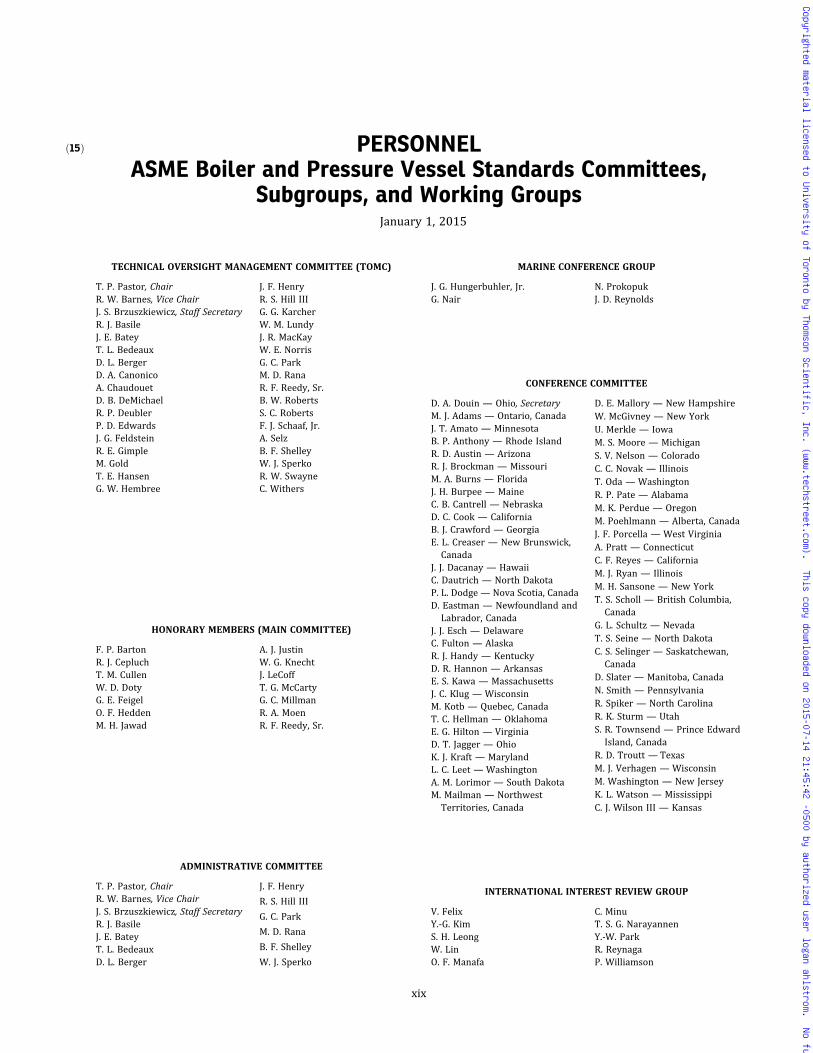
ð15Þ PERSONNELASME Boiler and Pressure Vessel Standards Committees,
Subgroups, and Working GroupsJanuary 1, 2015
TECHNICAL OVERSIGHT MANAGEMENT COMMITTEE (TOMC)
T. P. Pastor, ChairR. W. Barnes, Vice ChairJ. S. Brzuszkiewicz, Staff SecretaryR. J. BasileJ. E. BateyT. L. BedeauxD. L. BergerD. A. CanonicoA. ChaudouetD. B. DeMichaelR. P. DeublerP. D. EdwardsJ. G. FeldsteinR. E. GimpleM. GoldT. E. HansenG. W. Hembree
J. F. HenryR. S. Hill IIIG. G. KarcherW. M. LundyJ. R. MacKayW. E. NorrisG. C. ParkM. D. RanaR. F. Reedy, Sr.B. W. RobertsS. C. RobertsF. J. Schaaf, Jr.A. SelzB. F. ShelleyW. J. SperkoR. W. SwayneC. Withers
HONORARY MEMBERS (MAIN COMMITTEE)
F. P. BartonR. J. CepluchT. M. CullenW. D. DotyG. E. FeigelO. F. HeddenM. H. Jawad
A. J. JustinW. G. KnechtJ. LeCoffT. G. McCartyG. C. MillmanR. A. MoenR. F. Reedy, Sr.
ADMINISTRATIVE COMMITTEE
T. P. Pastor, ChairR. W. Barnes, Vice ChairJ. S. Brzuszkiewicz, Staff SecretaryR. J. BasileJ. E. BateyT. L. BedeauxD. L. Berger
J. F. Henry
R. S. Hill III
G. C. Park
M. D. Rana
B. F. Shelley
W. J. Sperko
MARINE CONFERENCE GROUP
J. G. Hungerbuhler, Jr.G. Nair
N. ProkopukJ. D. Reynolds
CONFERENCE COMMITTEE
D. A. Douin — Ohio, SecretaryM. J. Adams — Ontario, CanadaJ. T. Amato — MinnesotaB. P. Anthony — Rhode IslandR. D. Austin — ArizonaR. J. Brockman — MissouriM. A. Burns — FloridaJ. H. Burpee — MaineC. B. Cantrell — NebraskaD. C. Cook — CaliforniaB. J. Crawford — GeorgiaE. L. Creaser — New Brunswick,Canada
J. J. Dacanay — HawaiiC. Dautrich — North DakotaP. L. Dodge— Nova Scotia, CanadaD. Eastman — Newfoundland andLabrador, Canada
J. J. Esch — DelawareC. Fulton — AlaskaR. J. Handy — KentuckyD. R. Hannon — ArkansasE. S. Kawa — MassachusettsJ. C. Klug — WisconsinM. Kotb — Quebec, CanadaT. C. Hellman — OklahomaE. G. Hilton — VirginiaD. T. Jagger — OhioK. J. Kraft — MarylandL. C. Leet — WashingtonA. M. Lorimor — South DakotaM. Mailman — NorthwestTerritories, Canada
D. E. Mallory — New HampshireW. McGivney — New YorkU. Merkle — IowaM. S. Moore — MichiganS. V. Nelson — ColoradoC. C. Novak — IllinoisT. Oda — WashingtonR. P. Pate — AlabamaM. K. Perdue — OregonM. Poehlmann — Alberta, CanadaJ. F. Porcella — West VirginiaA. Pratt — ConnecticutC. F. Reyes — CaliforniaM. J. Ryan — IllinoisM. H. Sansone — New YorkT. S. Scholl — British Columbia,Canada
G. L. Schultz — NevadaT. S. Seine — North DakotaC. S. Selinger — Saskatchewan,Canada
D. Slater — Manitoba, CanadaN. Smith — PennsylvaniaR. Spiker — North CarolinaR. K. Sturm — UtahS. R. Townsend — Prince EdwardIsland, Canada
R. D. Troutt — TexasM. J. Verhagen — WisconsinM. Washington — New JerseyK. L. Watson — MississippiC. J. Wilson III — Kansas
INTERNATIONAL INTEREST REVIEW GROUP
V. FelixY.-G. KimS. H. LeongW. LinO. F. Manafa
C. MinuT. S. G. NarayannenY.-W. ParkR. ReynagaP. Williamson
xix
Copyrighted material licensed to University of Toronto by Thomson Scientific, Inc. (www.techstreet.com). This copy downloaded on 2015-07-14 21:45:42 -0500 by authorized user logan ahlstrom. No further reproduction or distribution is permitted.
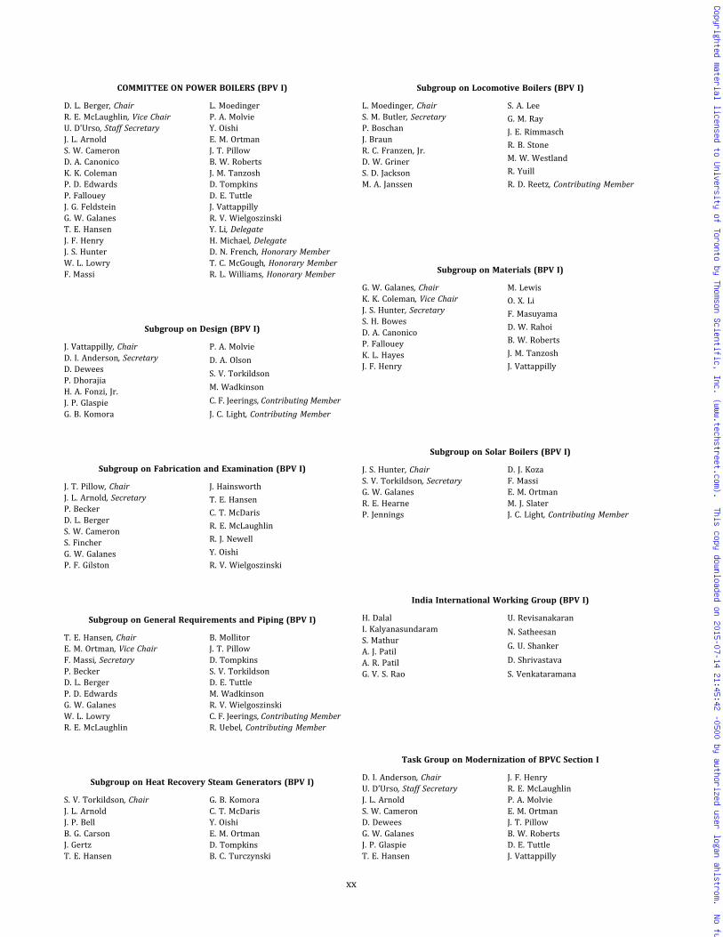
COMMITTEE ON POWER BOILERS (BPV I)
D. L. Berger, ChairR. E. McLaughlin, Vice ChairU. D'Urso, Staff SecretaryJ. L. ArnoldS. W. CameronD. A. CanonicoK. K. ColemanP. D. EdwardsP. FalloueyJ. G. FeldsteinG. W. GalanesT. E. HansenJ. F. HenryJ. S. HunterW. L. LowryF. Massi
L. MoedingerP. A. MolvieY. OishiE. M. OrtmanJ. T. PillowB. W. RobertsJ. M. TanzoshD. TompkinsD. E. TuttleJ. VattappillyR. V. WielgoszinskiY. Li, DelegateH. Michael, DelegateD. N. French, Honorary MemberT. C. McGough, Honorary MemberR. L. Williams, Honorary Member
Subgroup on Design (BPV I)
J. Vattappilly, ChairD. I. Anderson, SecretaryD. DeweesP. DhorajiaH. A. Fonzi, Jr.J. P. GlaspieG. B. Komora
P. A. Molvie
D. A. Olson
S. V. Torkildson
M. Wadkinson
C. F. Jeerings, Contributing Member
J. C. Light, Contributing Member
Subgroup on Fabrication and Examination (BPV I)
J. T. Pillow, ChairJ. L. Arnold, SecretaryP. BeckerD. L. BergerS. W. CameronS. FincherG. W. GalanesP. F. Gilston
J. Hainsworth
T. E. Hansen
C. T. McDaris
R. E. McLaughlin
R. J. Newell
Y. Oishi
R. V. Wielgoszinski
Subgroup on General Requirements and Piping (BPV I)
T. E. Hansen, ChairE. M. Ortman, Vice ChairF. Massi, SecretaryP. BeckerD. L. BergerP. D. EdwardsG. W. GalanesW. L. LowryR. E. McLaughlin
B. MollitorJ. T. PillowD. TompkinsS. V. TorkildsonD. E. TuttleM. WadkinsonR. V. WielgoszinskiC. F. Jeerings, Contributing MemberR. Uebel, Contributing Member
Subgroup on Heat Recovery Steam Generators (BPV I)
S. V. Torkildson, ChairJ. L. ArnoldJ. P. BellB. G. CarsonJ. GertzT. E. Hansen
G. B. KomoraC. T. McDarisY. OishiE. M. OrtmanD. TompkinsB. C. Turczynski
Subgroup on Locomotive Boilers (BPV I)
L. Moedinger, ChairS. M. Butler, SecretaryP. BoschanJ. BraunR. C. Franzen, Jr.D. W. GrinerS. D. JacksonM. A. Janssen
S. A. Lee
G. M. Ray
J. E. Rimmasch
R. B. Stone
M. W. Westland
R. Yuill
R. D. Reetz, Contributing Member
Subgroup on Materials (BPV I)
G. W. Galanes, ChairK. K. Coleman, Vice ChairJ. S. Hunter, SecretaryS. H. BowesD. A. CanonicoP. FalloueyK. L. HayesJ. F. Henry
M. Lewis
O. X. Li
F. Masuyama
D. W. Rahoi
B. W. Roberts
J. M. Tanzosh
J. Vattappilly
Subgroup on Solar Boilers (BPV I)
J. S. Hunter, ChairS. V. Torkildson, SecretaryG. W. GalanesR. E. HearneP. Jennings
D. J. KozaF. MassiE. M. OrtmanM. J. SlaterJ. C. Light, Contributing Member
India International Working Group (BPV I)
H. DalalI. KalyanasundaramS. MathurA. J. PatilA. R. PatilG. V. S. Rao
U. Revisanakaran
N. Satheesan
G. U. Shanker
D. Shrivastava
S. Venkataramana
Task Group on Modernization of BPVC Section I
D. I. Anderson, ChairU. D’Urso, Staff SecretaryJ. L. ArnoldS. W. CameronD. DeweesG. W. GalanesJ. P. GlaspieT. E. Hansen
J. F. HenryR. E. McLaughlinP. A. MolvieE. M. OrtmanJ. T. PillowB. W. RobertsD. E. TuttleJ. Vattappilly
xx
Copyrighted material licensed to University of Toronto by Thomson Scientific, Inc. (www.techstreet.com). This copy downloaded on 2015-07-14 21:45:42 -0500 by authorized user logan ahlstrom. No further reproduction or distribution is permitted.

COMMITTEE ON MATERIALS (BPV II)
J. F. Henry, ChairD. W. Rahoi, Vice ChairN. Lobo, Staff SecretaryF. AbeA. AppletonJ. CameronD. A. CanonicoA. ChaudouetP. FalloueyJ. R. FouldsD. W. GandyM. H. GilkeyM. GoldJ. F. GrubbJ. A. HallK. M. HottleM. KatcherO. X. LiF. MasuyamaR. K. NanstadB. W. Roberts
E. ShapiroM. J. SlaterR. C. SutherlinR. W. SwindemanJ. M. TanzoshD. TylerO. Oldani, DelegateH. D. Bushfield, ContributingMember
M. L. Nayyar, Contributing MemberE. G. Nisbett, Contributing MemberE. Upitis, Contributing MemberT. M. Cullen, Honorary MemberW. D. Doty, Honorary MemberW. D. Edsall, Honorary MemberG. C. Hsu, Honorary MemberR. A. Moen, Honorary MemberC. E. Spaeder, Jr., HonoraryMember
A. W. Zeuthen, Honorary Member
Executive Committee (BPV II)
J. F. Henry, ChairD. W. Rahoi, Vice ChairN. Lobo, Staff SecretaryA. AppletonA. ChaudouetJ. R. FouldsM. Gold
J. F. Grubb
R. W. Mikitka
B. W. Roberts
R. C. Sutherlin
R. W. Swindeman
J. M. Tanosh
Subgroup on External Pressure (BPV II)
R. W. Mikitka, ChairD. L. Kurle, Vice ChairJ. A. A. Morrow, SecretaryL. F. CampbellH. ChenD. S. GriffinJ. F. Grubb
J. R. Harris IIIM. H. JawadC. R. ThomasM. WadkinsonM. Katcher, Contributing MemberC. H. Sturgeon, ContributingMember
Subgroup on Ferrous Specifications (BPV II)
A. Appleton, ChairK. M. Hottle, Vice ChairP. Wittenbach, SecretaryH. ChenB. M. DingmanM. J. DosdourianP. FalloueyJ. D. FritzT. GrahamJ. M. GrockiJ. F. GrubbC. Hyde
D. S. Janikowski
L. J. Lavezzi
S. G. Lee
W. C. Mack
A. S. Melilli
K. E. Orie
J. Shick
E. Upitis
J. D. Wilson
R. Zawierucha
E. G. Nisbett, Contributing Member
Subgroup on International Material Specifications (BPV II)
A. Chaudouet, ChairO. X. Li, Vice ChairT. F. Miskell, SecretaryS. W. CameronD. A. CanonicoH. ChenP. FalloueyA. F. GarbolevskyD. O. Henry
M. Ishikawa
W. M. Lundy
A. R. Nywening
E. Upitis
F. Zeller
D. Kwon, Delegate
O. Oldani, Delegate
H. Lorenz, Contributing Member
Subgroup on Nonferrous Alloys (BPV II)
R. C. Sutherlin, ChairM. H. Gilkey, Vice ChairH. AnadaJ. CallandD. B. DenisJ. F. GrubbA. HeinoM. KatcherJ. A. McMasterL. Paul
D. W. RahoiW. RenE. ShapiroM. H. SkillingbergD. TylerJ. WeritzR. WrightR. ZawieruchaW. R. Apblett, Jr., ContributingMember
Subgroup on Physical Properties (BPV II)
J. F. Grubb, ChairH. D. BushfieldD. B. Denis
P. FalloueyE. Shapiro
Subgroup on Strength, Ferrous Alloys (BPV II)
J. M. Tanzosh, ChairM. J. Slater, SecretaryF. AbeH. AnadaD. A. CanonicoA. Di RienzoP. FalloueyJ. R. FouldsM. GoldJ. A. HallJ. F. HenryK. Kimura
S. W. KnowlesF. MasuyamaC. PearceD. W. RahoiB. W. RobertsM. S. SheltonJ. P. ShingledeckerR. W. SwindemanW. R. Apblett, Jr., ContributingMember
H. Murakami, ContributingMember
Subgroup on Strength of Weldments (BPV II & BPV IX)
W. F. Newell, Jr., ChairS. H. BowesK. K. ColemanP. D. FlennerJ. R. FouldsD. W. GandyM. GoldK. L. Hayes
J. F. HenryJ. PensoD. W. RahoiB. W. RobertsJ. P. ShingledeckerW. J. SperkoJ. P. Swezy, Jr.J. M. Tanzosh
Working Group on Materials Database (BPV II)
R. W. Swindeman, ChairN. Lobo, Staff SecretaryF. AbeJ. R. FouldsJ. F. HenryM. KatcherB. W. Roberts
R. C. SutherlinD. Andrei, Contributing MemberJ. L. Arnold, Contributing MemberW. Hoffelner, Contributing MemberT. Lazar, Contributing MemberD. T. Peters, Contributing MemberW. Ren, Contributing Member
xxi
Copyrighted material licensed to University of Toronto by Thomson Scientific, Inc. (www.techstreet.com). This copy downloaded on 2015-07-14 21:45:42 -0500 by authorized user logan ahlstrom. No further reproduction or distribution is permitted.

Working Group on Creep Strength Enhanced Ferritic Steels (BPV II)
J. F. Henry, ChairF. AbeS. H. BowesD. A. CanonicoK. K. ColemanG. CuminoP. D. FlennerJ. R. FouldsD. W. Gandy
M. Gold
F. Masuyama
W. F. Newell, Jr.
B. W. Roberts
W. J. Sperko
R. W. Swindeman
J. M. Tanzosh
R. G. Young
Working Group on Data Analysis (BPV II)
J. R. Foulds, ChairF. AbeM. GoldJ. F. GrubbJ. F. HenryM. Katcher
F. MasuyamaW. RenB. W. RobertsM. SubanovicM. J. SwindemanR. W. Swindeman
China International Working Group (BPV II)
B. Shou, ChairYong Zhang, Vice ChairX. Tong, SecretaryW. FangQ. C. FengS. HuoH. LiJ. LiS. LiZ. RongcanS. TanC. Wang
X. Wang
F. Yang
G. Yang
R. Ye
L. Yin
H. Zhang
X.-H. Zhang
Yingkai Zhang
Q. Zhao
S. Zhao
J. Zou
COMMITTEE ON CONSTRUCTION OF NUCLEAR FACILITYCOMPONENTS (BPV III)
R. S. Hill III, ChairR. B. Keating, Vice ChairJ. C. Minichiello, Vice ChairA. Byk, Staff SecretaryT. M. AdamsA. AppletonR. W. BarnesW. H. BorterC. W. BrunyT. D. BurchellJ. R. ColeR. P. DeublerA. C. EberhardtB. A. ErlerG. M. FosterW. HoffelnerR. M. JesseeR. I. JetterC. C. KimG. H. KooV. KostarevK. A. ManolyD. E. Matthews
R. P. McIntyreM. N. MitchellM. MorishitaD. K. MortonT. NagataR. F. Reedy, Sr.I. SaitoC. T. SmithW. K. Sowder, Jr.W. J. SperkoK. R. WichmanC. S. WithersY. H. Choi, DelegateT. Ius, DelegateH.-T. Wang, DelegateM. Zhou, Contributing MemberE. B. Branch, Honorary MemberG. D. Cooper, Honorary MemberW. D. Doty, Honorary MemberD. F. Landers, Honorary MemberR. A. Moen, Honorary MemberC. J. Pieper, Honorary Member
Subcommittee on Design (BPV III)
R. P. Deubler, ChairD. E. Matthews, Vice ChairG. L. Hollinger, SecretaryT. M. AdamsG. A. AntakiR. L. BrattonC. W. BrunyP. R. DonavinR. S. Hill IIIP. HirschbergM. H. JawadR. I. Jetter
R. B. Keating
R. A. Ladefian
K. A. Manoly
R. J. Masterson
M. N. Mitchell
W. J. O’Donnell, Sr.E. L. Pleins
T.-L. Sham
J. P. Tucker
K. Wright
J. Yang
Subgroup on Component Design (SC-D) (BPV III)
T. M. Adams, ChairR. B. Keating, Vice ChairS. Pellet, SecretaryG. A. AntakiS. AsadaJ. F. BallJ. R. ColeR. P. DeublerP. HirschbergH. KobayashiR. A. LadefianK. A. ManolyR. J. MastersonD. E. MatthewsJ. C. MinichielloD. K. Morton
T. M. MustoT. NagataA. N. NguyenE. L. PleinsI. SaitoG. C. SlagisJ. R. StinsonG. Z. TokarskiJ. P. TuckerP. VockK. R. WichmanC. WilsonJ. YangC. W. Bruny, Contributing MemberA. A. Dermenjian, ContributingMember
Working Group on Core Support Structures (SG-CD) (BPV III)
J. Yang, ChairJ. F. Kielb, SecretaryL. C. HartlessD. KeckT. LiszkaiH. S. Mehta
M. Nakajima
M. D. Snyder
A. Tsirigotis
R. Vollmer
J. T. Land, Contributing Member
Working Group on Design of Division 3 Containments(SG-CD) (BPV III)
D. K. Morton, ChairD. J. AmmermanG. BjorkmanG. BrozS. HorowitzD. W. LewisJ. C. Minichiello
E. L. Pleins
C. J. Temus
I. D. McInnes, Contributing Member
R. E. Nickell, Contributing Member
H. P. Shrivastava, ContributingMember
Working Group on HDPE Design of Components (SG-CD) (BPV III)
T. M. Musto, ChairJ. Ossmann, SecretaryT. M. AdamsT. A. BaconC. BasavarajuD. BurwellS. Choi
P. KrishnaswamyM. MartinJ. C. MinichielloD. P. MunsonF. J. Schaaf, Jr.R. StakenborghsH. E. Svetlik
xxii
Copyrighted material licensed to University of Toronto by Thomson Scientific, Inc. (www.techstreet.com). This copy downloaded on 2015-07-14 21:45:42 -0500 by authorized user logan ahlstrom. No further reproduction or distribution is permitted.
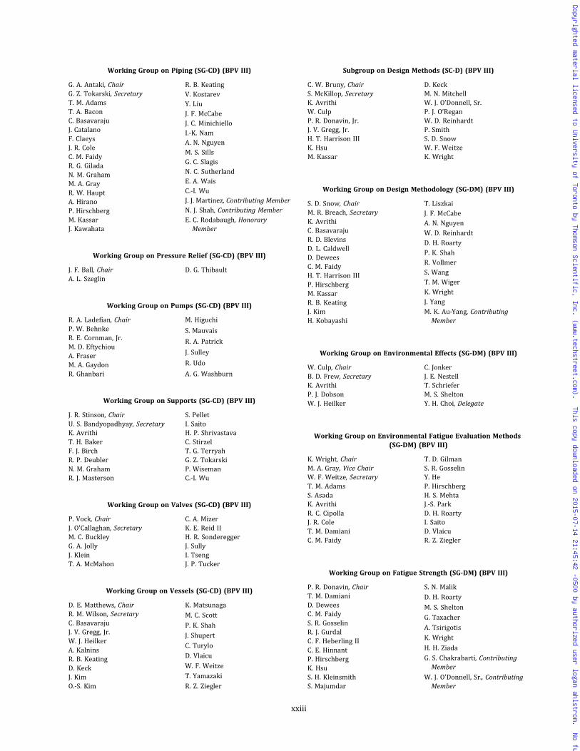
Working Group on Piping (SG-CD) (BPV III)
G. A. Antaki, ChairG. Z. Tokarski, SecretaryT. M. AdamsT. A. BaconC. BasavarajuJ. CatalanoF. ClaeysJ. R. ColeC. M. FaidyR. G. GiladaN. M. GrahamM. A. GrayR. W. HauptA. HiranoP. HirschbergM. KassarJ. Kawahata
R. B. KeatingV. KostarevY. LiuJ. F. McCabeJ. C. MinichielloI.-K. NamA. N. NguyenM. S. SillsG. C. SlagisN. C. SutherlandE. A. WaisC.-I. WuJ. J. Martinez, Contributing MemberN. J. Shah, Contributing MemberE. C. Rodabaugh, HonoraryMember
Working Group on Pressure Relief (SG-CD) (BPV III)
J. F. Ball, ChairA. L. Szeglin
D. G. Thibault
Working Group on Pumps (SG-CD) (BPV III)
R. A. Ladefian, ChairP. W. BehnkeR. E. Cornman, Jr.M. D. EftychiouA. FraserM. A. GaydonR. Ghanbari
M. Higuchi
S. Mauvais
R. A. Patrick
J. Sulley
R. Udo
A. G. Washburn
Working Group on Supports (SG-CD) (BPV III)
J. R. Stinson, ChairU. S. Bandyopadhyay, SecretaryK. AvrithiT. H. BakerF. J. BirchR. P. DeublerN. M. GrahamR. J. Masterson
S. PelletI. SaitoH. P. ShrivastavaC. StirzelT. G. TerryahG. Z. TokarskiP. WisemanC.-I. Wu
Working Group on Valves (SG-CD) (BPV III)
P. Vock, ChairJ. O'Callaghan, SecretaryM. C. BuckleyG. A. JollyJ. KleinT. A. McMahon
C. A. MizerK. E. Reid IIH. R. SondereggerJ. SullyI. TsengJ. P. Tucker
Working Group on Vessels (SG-CD) (BPV III)
D. E. Matthews, ChairR. M. Wilson, SecretaryC. BasavarajuJ. V. Gregg, Jr.W. J. HeilkerA. KalninsR. B. KeatingD. KeckJ. KimO.-S. Kim
K. Matsunaga
M. C. Scott
P. K. Shah
J. Shupert
C. Turylo
D. Vlaicu
W. F. Weitze
T. Yamazaki
R. Z. Ziegler
Subgroup on Design Methods (SC-D) (BPV III)
C. W. Bruny, ChairS. McKillop, SecretaryK. AvrithiW. CulpP. R. Donavin, Jr.J. V. Gregg, Jr.H. T. Harrison IIIK. HsuM. Kassar
D. KeckM. N. MitchellW. J. O’Donnell, Sr.P. J. O’ReganW. D. ReinhardtP. SmithS. D. SnowW. F. WeitzeK. Wright
Working Group on Design Methodology (SG-DM) (BPV III)
S. D. Snow, ChairM. R. Breach, SecretaryK. AvrithiC. BasavarajuR. D. BlevinsD. L. CaldwellD. DeweesC. M. FaidyH. T. Harrison IIIP. HirschbergM. KassarR. B. KeatingJ. KimH. Kobayashi
T. LiszkaiJ. F. McCabeA. N. NguyenW. D. ReinhardtD. H. RoartyP. K. ShahR. VollmerS. WangT. M. WigerK. WrightJ. YangM. K. Au-Yang, ContributingMember
Working Group on Environmental Effects (SG-DM) (BPV III)
W. Culp, ChairB. D. Frew, SecretaryK. AvrithiP. J. DobsonW. J. Heilker
C. JonkerJ. E. NestellT. SchrieferM. S. SheltonY. H. Choi, Delegate
Working Group on Environmental Fatigue Evaluation Methods(SG-DM) (BPV III)
K. Wright, ChairM. A. Gray, Vice ChairW. F. Weitze, SecretaryT. M. AdamsS. AsadaK. AvrithiR. C. CipollaJ. R. ColeT. M. DamianiC. M. Faidy
T. D. GilmanS. R. GosselinY. HeP. HirschbergH. S. MehtaJ.-S. ParkD. H. RoartyI. SaitoD. VlaicuR. Z. Ziegler
Working Group on Fatigue Strength (SG-DM) (BPV III)
P. R. Donavin, ChairT. M. DamianiD. DeweesC. M. FaidyS. R. GosselinR. J. GurdalC. F. Heberling IIC. E. HinnantP. HirschbergK. HsuS. H. KleinsmithS. Majumdar
S. N. Malik
D. H. Roarty
M. S. Shelton
G. Taxacher
A. Tsirigotis
K. Wright
H. H. Ziada
G. S. Chakrabarti, ContributingMember
W. J. O'Donnell, Sr., ContributingMember
xxiii
Copyrighted material licensed to University of Toronto by Thomson Scientific, Inc. (www.techstreet.com). This copy downloaded on 2015-07-14 21:45:42 -0500 by authorized user logan ahlstrom. No further reproduction or distribution is permitted.

Working Group on Graphite and Composites Design(SG-DM) (BPV III)
M. N. Mitchell, ChairM. W. Davies, Vice ChairC. A. Sanna, Staff SecretaryT. D. Burchell, SecretaryA. AppletonR. L. BrattonS. CadellS.-H. ChiA. CovacS. W. Doms
S. F. Duffy
S. T. Gonczy
Y. Katoh
J. Ossmann
M. Roemmler
N. Salstrom
T. Shibata
S. Yu
G. L. Zeng
Working Group on Probabilistic Methods in Design(SG-DM) (BPV III)
P. J. O'Regan, ChairM. Golliet, SecretaryT. AsayamaK. AvrithiM. R. Graybeal
D. O. HenryR. S. Hill IIIM. MorishitaN. A. PalmI. Saito
Special Working Group on Computational Modeling for ExplicitDynamics (SG-DM) (BPV III)
G. Bjorkman, ChairD. J. Ammerman, SecretaryM. R. BreachG. BrozJ. JordanD. MolitorisJ. Piotter
W. D. Reinhardt
P. Y.-K. Shih
S. D. Snow
C.-F. Tso
M. C. Yaksh
U. Zencker
Subgroup on Elevated Temperature Design (SC-D) (BPV III)
T.-L. Sham, ChairT. AsayamaC. Becht IVF. W. BrustP. CarterJ. F. CervenkaB. F. HantzW. HoffelnerA. B. HullM. H. JawadR. I. Jetter
G. H. Koo
M. Li
S. Majumdar
J. E. Nestell
W. J. O'Donnell, Sr.
R. W. Swindeman
D. S. Griffin, Contributing Member
W. J. Koves, Contributing Member
D. L. Marriott, ContributingMember
Working Group on Allowable Stress Criteria (SG-ETD) (BPV III)
R. W. Swindeman, ChairR. Wright, SecretaryJ. R. FouldsK. KimuraM. LiS. N. Malik
J. E. Nestell
W. Ren
B. W. Roberts
M. Sengupta
T.-I. Sham
Working Group on Analysis Methods (SG-ETD) (BPV III)
P. Carter, ChairM. J. Swindeman, SecretaryM. AndoM. R. Breach
R. I. JetterS. KrishnamurthyT.-I. ShamD. K. Williams
Working Group on Creep-Fatigue and Negligible Creep (SG-ETD)(BPV III)
T. Asayama, ChairM. Li, SecretaryF. W. BrustP. CarterR. I. Jetter
G. H. KooB.-L. LyowS. N. MalikH. QianT.-I. Sham
Working Group on Elevated Temperature Construction (SG-ETD)(BPV III)
M. H. Jawad, ChairB. Mollitor, SecretaryD. I. AndersonR. G. BrownD. DeweesJ. P. GlaspieB. F. Hantz
G. L. HollingerR. I. JetterS. KrishnamurthyA. MannD. L. MarriottM. N. MitchellC. Nadarajah
Working Group on High Temperature Flaw Evaluation (SG-ETD)(BPV III)
F. W. Brust, ChairN. BroomP. CarterW. HoffelnerS. N. Malik
D. L. RudlandP. J. RushD.-J. ShimS. X. Xu
Subgroup on General Requirements (BPV III)
R. P. McIntyre, ChairL. M. Plante, SecretaryV. ApostolescuA. AppletonS. BellJ. R. BerryB. K. BoboJ. DeKleineJ. V. GardinerG. GrattiJ. W. HighlandsG. V. ImbroK. A. Kavanagh
Y.-S. KimM. R. MinickE. C. RenaudD. J. RoszmanC. T. SmithW. K. Sowder, Jr.G. E. SzabaturaT. G. TerryahD. M. VickeryC. S. WithersH. Michael, DelegateG. L. Hollinger, ContributingMember
Working Group on Duties and Responsibilities (SG-GR) (BPV III)
J. V. Gardiner, ChairG. L. Hollinger, SecretaryS. BellJ. R. BerryJ. DeKleineN. DeSantisY. Diaz-CastilloE. L. Farrow
G. Gratti
B. N. Juarez
K. A. Kavanagh
J. M. Lyons
L. M. Plante
D. J. Roszman
T. G. Terryah
xxiv
Copyrighted material licensed to University of Toronto by Thomson Scientific, Inc. (www.techstreet.com). This copy downloaded on 2015-07-14 21:45:42 -0500 by authorized user logan ahlstrom. No further reproduction or distribution is permitted.
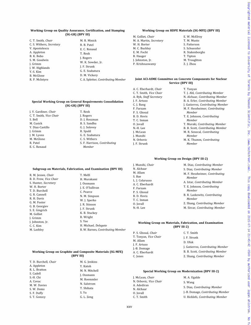
Working Group on Quality Assurance, Certification, and Stamping(SG-GR) (BPV III)
C. T. Smith, ChairC. S. Withers, SecretaryV. ApostolescuA. AppletonB. K. BoboS. M. GoodwinJ. GrimmJ. W. HighlandsY.-S. KimB. McGloneR. P. McIntyre
M. R. Minick
R. B. Patel
E. C. Renaud
T. Rezk
J. Rogers
W. K. Sowder, Jr.
J. F. Strunk
G. E. Szabatura
D. M. Vickery
C. A. Spletter, Contributing Member
Special Working Group on General Requirements Consolidation(SG-GR) (BPV III)
J. V. Gardiner, ChairC. T. Smith, Vice ChairS. BellM. CusickY. Diaz-CastilloJ. GrimmJ. M. LyonsM. McGloneR. PatelE. C. Renaud
T. RezkJ. RogersD. J. RoszmanB. S. SandhuG. J. SoloveyR. SpuhlG. E. SzabaturaC. S. WithersS. F. Harrison, ContributingMember
Subgroup on Materials, Fabrication, and Examination (BPV III)
R. M. Jessee, ChairB. D. Frew, Vice ChairS. Hunter, SecretaryW. H. BorterT. D. BurchellG. R. CannellR. H. DavisG. M. FosterG. B. GeorgievS. E. GingrichM. GollietJ. GrimmJ. Johnston, Jr.C. C. KimM. Lashley
T. MelfiH. MurakamiJ. OssmannJ. E. O’SullivanC. PearceN. M. SimpsonW. J. SperkoJ. R. StinsonJ. F. StrunkK. B. StuckeyR. WrightS. YeeH. Michael, DelegateR. W. Barnes, Contributing Member
Working Group on Graphite and Composite Materials (SG-MFE)(BPV III)
T. D. Burchell, ChairA. AppletonR. L. BrattonS. CadellS.-H. ChiA. CovacM. W. DaviesS. W. DomsS. F. DuffyS. T. Gonzcy
M. G. Jenkins
Y. Katoh
M. N. Mitchell
J. Ossmann
M. Roemmler
N. Salstrom
T. Shibata
S. Yu
G. L. Zeng
Working Group on HDPE Materials (SG-MFE) (BPV III)
M. Golliet, ChairM. A. Martin, SecretaryW. H. BorterM. C. BuckleyE. M. FochtB. HaugerJ. Johnston, Jr.P. Krishnaswamy
E. W. McElroyT. M. MustoS. PattersonS. SchuesslerR. StakenborghsT. TiptonM. TroughtonZ. J. Zhou
Joint ACI-ASME Committee on Concrete Components for NuclearService (BPV III)
A. C. Eberhardt, ChairC. T. Smith, Vice ChairA. Byk, Staff SecretaryJ. F. ArtusoC. J. BangF. FarzamP. S. GhosalB. D. HovisT. C. InmanO. JovallN.-H. LeeJ. McLeanJ. MunshiN. OrbovicJ. F. Strunk
T. TonyanT. J. Ahl, Contributing MemberN. Alchaar, Contributing MemberB. A. Erler, Contributing MemberJ. Gutierrez, Contributing MemberM. F. Hessheimer, ContributingMember
T. E. Johnson, ContributingMember
T. Muraki, Contributing MemberB. B. Scott, Contributing MemberM. R. Senecal, ContributingMember
M. K. Thumm, ContributingMember
Working Group on Design (BPV III-2)
J. Munshi, ChairN. AlchaarM. AllamS. BaeL. J. ColarussoA. C. EberhardtF. FarzamP. S. GhosalB. D. HovisT. C. InmanO. JovallN.-H. Lee
M. Diaz, Contributing Member
S. Diaz, Contributing Member
M. F. Hessheimer, ContributingMember
A. Istar, Contributing Member
T. E. Johnson, ContributingMember
B. R. Laskewitz, ContributingMember
Z. Shang, Contributing Member
M. Sircar, Contributing Member
Working Group on Materials, Fabrication, and Examination(BPV III-2)
P. S. Ghosal, ChairT. Tonyan, Vice ChairM. AllamJ. F. ArtusoJ.-B. DomageA. C. EberhardtC. Jones
C. T. Smith
J. F. Strunk
D. Ufuk
J. Gutierrez, Contributing Member
B. B. Scott, Contributing Member
Z. Shang, Contributing Member
Special Working Group on Modernization (BPV III-2)
J. McLean, ChairN. Orbovic, Vice ChairA. AdediranN. AlchaarO. JovallC. T. Smith
M. A. Ugalde
S. Wang
S. Diaz, Contributing Member
J.-B. Domage, Contributing Member
U. Ricklefs, Contributing Member
xxv
Copyrighted material licensed to University of Toronto by Thomson Scientific, Inc. (www.techstreet.com). This copy downloaded on 2015-07-14 21:45:42 -0500 by authorized user logan ahlstrom. No further reproduction or distribution is permitted.
Subgroup on Containment Systems for Spent Fuel and High-LevelWaste Transport Packagings (BPV III)
D. K. Morton, ChairG. M. Foster, Vice ChairG. R. Cannell, SecretaryG. AbramczykD. J. AmmermanG. BjorkmanS. HorowitzD. W. LewisP. E. McConnellR. E. NickellE. L. Pleins
R. H. Smith
G. J. Solovey
C. J. Temus
W. H. Borter, Contributing Member
R. S. Hill III, Contributing Member
A. B. Meichler, ContributingMember
T. Saegusa, Contributing Member
N. M. Simpson, ContributingMember
Subgroup on Fusion Energy Devices (BPV III)
W. K. Sowder, Jr., ChairD. Andrei, Staff SecretaryD. J. Roszman, SecretaryR. W. BarnesB. R. DoshiM. HiguchiG. HoltmeierM. KalseyK. A. KavanaghH. J. KimK. Kim
I. KimihiroS. LeeG. LiX. LiP. MokariaT. R. MuldoonM. PortonY. SongM. TrosenC. WaldonI. J. Zatz
Working Group on General Requirements (BPV III-4)
W. K. Sowder, Jr., Chair
Working Group on In-Vessel Components (BPV III-4)
M. Kalsey, Chair
Working Group on Magnets (BPV III-4)
K. Kim, Chair
Working Group on Materials (BPV III-4)
M. Porton, Chair
Working Group on Vacuum Vessels (BPV III-4)
I. Kimihiro, Chair B. R. Doshi
Subgroup on High Temperature Reactors (BPV III)
M. Morishita, ChairR. I. Jetter, Vice ChairT.-L. Sham, SecretaryN. BroomT. D. BurchellW. Hoffelner
G.-H. KooD. K. MortonJ. E. NestellN. N. RayX. Li, Contributing MemberL. Shi, Contributing Member
Working Group on High Temperature Gas-Cooled Reactors(BPV III-5)
J. E. Nestell, ChairM. Sengupta, SecretaryN. BroomT. D. BurchellR. S. Hill IIIE. V. ImbroR. I. JetterY. W. Kim
T. R. Lupold
S. N. Malik
D. L. Marriott
D. K. Morton
T.-L. Sham
X. Li, Contributing Member
L. Shi, Contributing Member
Working Group on High Temperature Liquid-Cooled Reactors(BPV III-5)
T.-L. Sham, ChairT. Asayama, SecretaryM. ArcaroR. W. BarnesP. CarterM. E. CohenA. B. HullR. I. Jetter
G. H. Koo
M. Li
S. Majumdar
M. Morishita
J. E. Nestell
X. Li, Contributing Member
G. Wu, Contributing Member
Executive Committee (BPV III)
R. S. Hill III, ChairA. Byk, Staff SecretaryT. M. AdamsC. W. BrunyR. P. DeublerA. C. EberhardtR. M. JesseeR. B. Keating
R. P. McIntyre
J. C. Minichiello
M. Morishita
D. K. Morton
C. A. Sanna
T.-L. Sham
W. K. Sowder, Jr.
China International Working Group (BPV III)
J. Yan, ChairW. Tang, Vice ChairC. A. Sanna, Staff SecretaryY. He, SecretaryH. GeZ. HanJ. JianY. JingF. KaiD. KangX. LiY. LiB. LiangH. LinS. LinJ. LiuS. LiuW. LiuK. MaoW. Pei
G. SunG. TangY. TuY. WangH. WuX. WuZ. WuS. XueZ. YanC. YeZ. YinS. ZaozhanG. ZhangK. ZhangW. ZhangG. ZhaoW. ZhaoY. ZhongZ. ZhongG. Zhu
xxvi
Copyrighted material licensed to University of Toronto by Thomson Scientific, Inc. (www.techstreet.com). This copy downloaded on 2015-07-14 21:45:42 -0500 by authorized user logan ahlstrom. No further reproduction or distribution is permitted.
Germany International Working Group (BPV III)
C. Huttner, ChairH.-R. Bath, SecretaryB. ArndtM. BauerG. DaumL. GerstnerG. HaenleK.-H. HerterU. JendrichG. KramarzC. KrumbW. MayingerD. Moehring
D. OstermannG. RoosJ. RudolphC. A. SannaH. SchauC. A. SpletterR. TrieglaffP. VöllmeckeJ. WendtF. WilleM. WinterN. Wirtz
India International Working Group (BPV III)
B. Basu, ChairG. Mathivanan, Vice ChairC. A. Sanna, Staff SecretaryS. B. Parkash, SecretaryV. BhasinP. ChellapandiS. Jalaldeen
D. Kulkarni
S. A. Kumar De
N. M. Nadaph
M. Ponnusamy
R. N. Sen
A. Sundararajan
Korea International Working Group (BPV III)
G. H. Koo, ChairS. S. Hwang, Vice ChairO.-S. Kim, SecretaryH. S. ByunS. ChoiJ.-Y. HongN.-S. HuhJ.-K. HwangC. JangI. I. JeongH. J. KimJ. KimJ.-S. KimK. KimY.-B. KimY.-S. Kim
D. KwonB. LeeD. LeeSanghoon LeeSangil LeeD. J. LimH. LimI.-K. NamB. NohC.-K. OhC. ParkJ.-S. ParkT. ShinS. SongO. Yoo
Special Working Group on Editing and Review (BPV III)
D. K. Morton, ChairR. L. BrattonR. P. DeublerA. C. EberhardtR. I. Jetter
J. C. MinichielloL. M. PlanteR. F. Reedy, Sr.W. K. Sowder, Jr.C. Wilson
Special Working Group on HDPE Stakeholders (BPV III)
D. Burwell, ChairS. Patterson, SecretaryT. M. AdamsS. BruceS. ChoiC. M. FaidyE. M. FochtM. GollietJ. GrimesR. M. JesseeJ. Johnston, Jr.D. Keller
M. LashleyT. R. LupoldK. A. ManolyD. P. MunsonT. M. MustoJ. E. O’SullivanM. A. RichterV. RohatgiF. J. Schaaf, Jr.R. StakenborghsM. TroughtonZ. J. Zhou
Special Working Group on Honors and Awards (BPV III)
R. M. Jessee, ChairA. AppletonR. W. Barnes
J. R. ColeD. E. MatthewsJ. C. Minichiello
Special Working Group on Industry Experience for New Plants(BPV III & BPV XI)
G. M. Foster, ChairJ. T. Lindberg, ChairH. L. Gustin, SecretaryJ. Ossmann, SecretaryT. L. ChanD. R. GrahamP. J. HennesseyD. O. HenryJ. HoncharikE. V. ImbroC. G. KimO.-S. Kim
Y.-S. Kim
K. Matsunaga
D. E. Matthews
R. E. McLaughlin
E. L. Pleins
D. W. Sandusky
D. M. Swann
T. Tsuruta
E. R. Willis
R. M. Wilson
S. M. Yee
Special Working Group on International Meetings (BPV III)
C. T. Smith, ChairA. Byk, Staff SecretaryT. D. BurchellS. W. CameronJ. R. ColeR. L. Crane
G. M. Foster
R. S. Hill III
M. N. Mitchell
R. F. Reedy, Sr.
C. A. Sanna
Special Working Group on New Advanced Light Water Reactor PlantConstruction Issues (BPV III)
E. L. Pleins, ChairM. C. Scott, SecretaryA. CardilloP. J. CocoB. GilliganJ. HoncharikG. V. ImbroO.-S Kim
M. KrisJ. C. MinichielloD. W. SanduskyC. A. SannaR. R. StevensonR. TroficantoM. L. WilsonJ. Yan
Special Working Group on Regulatory Interface (BPV III)
G. V. Imbro, ChairS. Bell, SecretaryA. CardilloA. A. DermenjianB. N. JuarezK. Matsunaga
D. E. MatthewsA. T. Roberts IIIR. R. StevensonD. TeraoM. L. WilsonR. A. Yonekawa
COMMITTEE ON HEATING BOILERS (BPV IV)
T. L. Bedeaux, ChairJ. A. Hall, Vice ChairG. Moino, Staff SecretaryB. CalderonJ. CallandJ. P. ChicoineC. M. DoveA. HeinoB. J. IskeP. A. Molvie
R. E. Olson
M. Wadkinson
R. V. Wielgoszinski
H. Michael, Delegate
D. Picart, Delegate
S. V. Voorhees, ContributingMember
J. L. Kleiss, Alternate
W. L. Haag, Jr., Honorary Member
xxvii
Copyrighted material licensed to University of Toronto by Thomson Scientific, Inc. (www.techstreet.com). This copy downloaded on 2015-07-14 21:45:42 -0500 by authorized user logan ahlstrom. No further reproduction or distribution is permitted.
Subgroup on Care and Operation of Heating Boilers (BPV IV)
M. Wadkinson, ChairT. L. BedeauxJ. Calland
J. A. HallP. A. Molvie
Subgroup on Cast Iron Boilers (BPV IV)
J. P. Chicoine, ChairT. L. Bedeaux, Vice ChairC. M. Dove
J. M. DownsJ. A. HallJ. L. Kleiss
Subgroup on Materials (BPV IV)
J. A. Hall, ChairM. Wadkinson, Vice ChairJ. CallandJ. M. Downs
A. HeinoB. J. IskeJ. L. KleissE. Rightmier
Subgroup on Water Heaters (BPV IV)
J. Calland, ChairJ. P. ChicoineB. J. Iske
R. E. OlsonT. E. Trant
Subgroup on Welded Boilers (BPV IV)
J. Calland, ChairT. L. BedeauxB. CalderonJ. L. Kleiss
P. A. MolvieR. E. OlsonM. WadkinsonR. V. Wielgoszinski
COMMITTEE ON NONDESTRUCTIVE EXAMINATION (BPV V)
G. W. Hembree, ChairF. B. Kovacs, Vice ChairJ. S. Brzuszkiewicz, Staff SecretaryS. J. AkrinC. A. AndersonJ. E. BateyA. S. BirksP. L. BrownM. A. BurnsB. CaccamiseN. Y. FaranssoN. A. FinneyA. F. GarbolevskyJ. F. Halley
J. W. HoufS. A. JohnsonR. W. KruzicC. MayA. B. NagelT. L. PlasekF. J. SattlerG. M. Gatti, DelegateX. Guiping, DelegateB. D. Laite, AlternateH. C. Graber, Honorary MemberO. F. Hedden, Honorary MemberJ. R. MacKay, Honorary MemberT. G. McCarty, Honorary Member
Subgroup on General Requirements/Personnel Qualifications andInquiries (BPV V)
F. B. Kovacs, ChairJ. W. Houf, Vice ChairS. J. AkrinC. A. AndersonJ. E. BateyA. S. BirksC. EmslanderN. Y. Faransso
N. A. Finney
G. W. Hembree
S. A. Johnson
D. I. Morris
A. B. Nagel
J. P. Swezy, Jr., ContributingMember
Special Working Group on NDE Resource Support (SG-GR/PQ & I)(BPV V)
N. A. Finney, ChairD. AdkinsJ. AndersonT. G. BollhalterC. T. BrownN. Carter
J. L. Garner
M. Ghahremani
J. W. Mefford, Jr.
M. Sens
D. Van Allen
Subgroup on Surface Examination Methods (BPV V)
S. A. Johnson, ChairJ. Halley, Vice ChairS. J. AkrinJ. E. BateyA. S. BirksP. L. BrownB. CaccamiseN. Y. FaranssoN. FarenbaughN. A. Finney
G. W. Hembree
R. W. Kruzic
B. D. Laite
C. May
L. E. Mullins
A. B. Nagel
F. J. Sattler
P. Shaw
G. M. Gatti, Delegate
Subgroup on Volumetric Methods (BPV V)
A. B. Nagel, ChairN. A. Finney, Vice ChairS. J. AkrinJ. E. BateyP. L. BrownB. CaccamiseN. Y. FaranssoA. F. GarbolevskyJ. F. HalleyR. W. Hardy
G. W. HembreeS. A. JohnsonF. B. KovacsR. W. KruzicC. MayL. E. MullinsT. L. PlasekF. J. SattlerM. TorokG. M. Gatti, Delegate
Working Group on Acoustic Emissions (SG-VM) (BPV V)
N. Y. Faransso, ChairJ. E. Batey, Vice Chair
S. R. DoctorR. K. Miller
Working Group on Radiography (SG-VM) (BPV V)
B. Caccamise, ChairF. B. Kovacs, Vice ChairS. J. AkrinJ. E. BateyP. L. BrownC. EmslanderN. Y. FaranssoA. F. GarbolevskyR. W. HardyG. W. Hembree
S. A. Johnson
R. W. Kruzic
B. D. Laite
S. Mango
C. May
R. J. Mills
A. B. Nagel
T. L. Plasek
M. Torok
Working Group on Ultrasonics (SG-VM) (BPV V)
N. A. Finney, ChairJ. F. Halley, Vice ChairB. CaccamiseK. J. ChizenJ. M. DavisN. Y. FaranssoP. T. HayesS. A. Johnson
R. W. Kruzic
B. D. Laite
C. May
L. E. Mullins
A. B. Nagel
F. J. Sattler
M. Torok
xxviii
Copyrighted material licensed to University of Toronto by Thomson Scientific, Inc. (www.techstreet.com). This copy downloaded on 2015-07-14 21:45:42 -0500 by authorized user logan ahlstrom. No further reproduction or distribution is permitted.

Working Group on GuidedWave Ultrasonic Testing (SG-VM) (BPV V)
N. Y. Faransso, ChairJ. E. Batey, Vice ChairD. AlleyneN. AmirJ. F. Halley
S. A. JohnsonG. M. LightP. MudgeM. J. QuarryJ. Vanvelsor
COMMITTEE ON PRESSURE VESSELS (VIII)
R. J. Basile, ChairS. C. Roberts, Vice ChairS. J. Rossi, Staff SecretaryT. Schellens, Staff SecretaryG. Aurioles, Sr.V. BogosianJ. CameronA. ChaudouetD. B. DeMichaelJ. P. GlaspieJ. F. GrubbL. E. Hayden, Jr.G. G. KarcherD. L. KurleK. T. LauM. D. LowerR. MahadeenR. W. MikitkaU. R. MillerT. W. NortonT. P. PastorD. T. PetersM. J. Pischke
M. D. RanaG. B. Rawls, Jr.F. L. RichterC. D. RoderyE. SoltowD. A. SwansonJ. P. Swezy, Jr.S. TeradaE. UpitisP. A. McGowan, DelegateH. Michael, DelegateK. Oyamada, DelegateM. E. Papponetti, DelegateD. Rui, DelegateT. Tahara, DelegateM. Gold, Contributing MemberW. S. Jacobs, Contributing MemberK. Mokhtarian, ContributingMember
C. C. Neely, Contributing MemberA. Selz, Contributing MemberK. K. Tam, Contributing Member
Subgroup on Design (BPV VIII)
D. A. Swanson, ChairJ. C. Sowinski, Vice ChairM. Faulkner, SecretaryG. Aurioles, Sr.S. R. BabkaO. A. BarskyR. J. BasileM. R. BreachF. L. BrownD. ChandiramaniB. F. HantzC. E. HinnantC. S. HinsonM. H. JawadD. L. KurleM. D. LowerR. W. MikitkaU. R. Miller
T. P. PastorM. D. RanaG. B. Rawls, Jr.S. C. RobertsC. D. RoderyD. SrnicJ. VattappillyR. A. WhippleK. XuK. Oyamada, DelegateM. E. Papponetti, DelegateW. S. Jacobs, Contributing MemberP. K. Lam, Contributing MemberK. Mokhtarian, ContributingMember
A. Selz, Contributing MemberS. C. Shah, Contributing MemberK. K. Tam, Contributing Member
Working Group on Design-By-Analysis (BPV III)
B. F. Hantz, ChairT. W. Norton, SecretaryR. G. BrownD. DeweesR. D. DixonZ. GuC. E. HinnantR. JainM. H. Jawad
S. KrishnamurthyA. MannG. A. MillerC. NadarajahM. D. RanaT. G. SeippM. A. ShahS. TeradaD. Arnett, Contributing Member
Subgroup on Fabrication and Inspection (BPV VIII)
C. D. Rodery, ChairJ. P. Swezy, Jr., Vice ChairB. R. Morelock, SecretaryL. F. CampbellD. I. MorrisO. MuletM. J. PischkeM. J. RiceB. F. Shelley
P. L. Sturgill
E. A. Whittle
K. Oyamada, Delegate
W. J. Bees, Contributing Member
W. S. Jacobs, Contributing Member
J. Lee, Contributing Member
R. Uebel, Contributing Member
E. Upitis, Contributing Member
Subgroup on General Requirements (BPV VIII)
M. D. Lower, ChairJ. P. Glaspie, Vice ChairF. L. Richter, SecretaryR. J. BasileV. BogosianD. T. DavisD. B. DeMichaelM. FaulkenerL. E. Hayden, Jr.K. T. Lau
A. S. OlivaresT. P. PastorS. C. RobertsJ. C. SowinskiP. SperanzaD. B. StewartD. A. SwansonR. UebelK. Oyamada, DelegateC. C. Neely, Contributing Member
Task Group on U-2(g) (BPV VIII)
S. R. BabkaR. J. BasileD. K. ChandiramaniR. MahadeenU. R. MillerT. W. NortonT. P. Pastor
R. F. Reedy, Sr.S. C. RobertsM. A. Shah, Jr.D. SrnicD. A. SwansonR. UebelK. K. Tam, Contributing Member
Subgroup on Heat Transfer Equipment (BPV VIII)
G. Aurioles, Sr., ChairP. Matkovics, SecretaryD. AngstadtS. R. BabkaM. BahadoriJ. H. BarbeeO. A. BarskyI. G. CampbellA. ChaudouetM. D. ClarkS. JeyakumarG. G. KarcherD. L. KurleB. J. Lerch
R. MahadeenS. MayeuxU. R. MillerT. W. NortonK. OyamadaD. SrnicA. M. VoytkoR. P. WibergF. E. Jehrio, Contributing MemberJ. Mauritz, Contributing MemberF. Osweiller, Contributing MemberR. Tiwari, Contributing MemberS. Yokell, Contributing MemberS. M. Caldwell, Honorary Member
Task Group on Plate Heat Exchangers (BPV VIII)
M. J. Pischke, ChairS. R. BabkaS. FlynnJ. F. GrubbF. HamtakJ. E. Lane
R. MahadeenP. MetkovicsD. I. MorrisC. M. RomeroE. SoltowD. Srnic
xxix
Copyrighted material licensed to University of Toronto by Thomson Scientific, Inc. (www.techstreet.com). This copy downloaded on 2015-07-14 21:45:42 -0500 by authorized user logan ahlstrom. No further reproduction or distribution is permitted.
Subgroup on High Pressure Vessels (BPV VIII)
D. T. Peters, ChairR. D. Dixon, Vice ChairR. T. Hallman, Vice ChairA. P. Maslowski, Staff SecretaryL. P. AntalffyR. C. BielP. N. ChakuR. CordesL. FridlundD. M. FryerA. H. HonzaJ. A. KappJ. KeltjensA. K. KhareN. McKieS. C. Mordre
G. T. NelsonE. A. RodriguezE. D. RollK. C. Simpson, Jr.D. L. StangF. W. TatarS. TeradaJ. L. TraudR. WinkK.-J. YoungK. Oyamada, DelegateR. M. Hoshman, ContributingMember
G. J. Mraz, Contributing MemberD. J. Burns, Honorary MemberE. H. Perez, Honorary Member
Subgroup on Materials (BPV VIII)
J. F. Grubb, ChairJ. Cameron, Vice ChairP. G. Wittenbach, SecretaryA. Di RienzoJ. D. FritzM. KatcherM. KowalczykW. M. LundyJ. PensoD. W. Rahoi
R. C. Sutherlin
E. Upitis
K. Xu
K. Oyamada, Delegate
G. S. Dixit, Contributing Member
M. Gold, Contributing Member
J. A. McMaster, ContributingMember
E. G. Nisbett, Contributing Member
Subgroup on Toughness (BPV II & BPV VIII)
D. L. Kurle, ChairK. Xu, Vice ChairR. J. BasileW. S. JacobsM. D. RanaF. L. RichterK. SubramanianD. A. Swanson
J. P. Swezy, Jr.
E. Upitis
J. Vattappilly
K. Oyamada, Delegate
K. Mokhtarian, ContributingMember
C. C. Neely, Contributing Member
Subgroup on Graphite Pressure Equipment (BPV VIII)
E. Soltow, ChairG. C. BechererT. F. BonnF. L. Brown
M. R. MinickA. A. StupicaA. Viet
Italy International Working Group (BPV VIII)
G. Pontiggia, ChairA. Veroni, SecretaryB. G. AlboraliP. AngeliniR. BoattiA. CamanniP. ContiP. L. DinelliF. FincoL. GaetaniA. Ghidini
M. Guglielmetti
P. Mantovani
M. Maroni
M. Massobrio
L. Moracchioli
L. Possenti
C. Sangaletti
A. Teli
I. Venier
G. Gobbi, Contributing Member
Special Working Group on Bolted Flanged Joints (BPV VIII)
R. W. Mikitka, ChairG. D. BibelW. BrownH. ChenW. J. Koves
M. MorishitaJ. R. PayneG. B. Rawls, Jr.M. S. Shelton
Working Group on Design (BPV VIII Div. 3)
J. Keltjens, ChairC. Becht VR. C. BielR. CordesR. D. DixonL. FridlundR. T. HallmanG. M. MitalS. C. MordreG. T. NelsonD. T. PetersE. D. Roll
K. C. SimpsonD. L. StangK. SubramanianS. TeradaJ. L. TraudR. WinkY. XuF. Kirkemo, Contributing MemberD. J. Burns, Honorary MemberD. M. Fryer, Honorary MemberG. J. Mraz, Honorary MemberE. H. Perez, Honorary Member
Working Group on Materials (BPV VIII Div. 3)
F. W. Tatar, ChairL. P. AntalffyP. N. Chaku
J. A. KappA. K. Khare
Task Group on Impulsively Loaded Vessels (BPV VIII)
E. A. Rodriguez, ChairP. O. Leslie, SecretaryG. A. AntakiJ. K. AsahinaD. D. BarkerA. M. ClaytonJ. E. Didlake, Jr.T. A. DuffeyB. L. HaroldsenK. HayashiD. HildingK. W. KingR. Kitamura
R. A. Leishear
R. E. Nickell
F. Ohlson
C. Romero
N. Rushton
J. H. Stofleth
Q. Dong, Contributing Member
H.-P. Schildberg, ContributingMember
J. E. Shepherd, ContributingMember
M. Yip, Contributing Member
Subgroup on Interpretations (BPV VIII)
U. R. Miller, ChairT. Schellens, Staff SecretaryG. Aurioles, Sr.R. J. BasileJ. CameronR. D. DixonJ. F. GrubbD. L. KurleM. D. LowerR. Mahadeen
D. T. Peters
S. C. Roberts
C. D. Rodery
D. B. Stewart
P. L. Sturgill
D. A. Swanson
J. P. Swezy, Jr.
J. Vattappilly
T. P. Pastor, Contributing Member
xxx
Copyrighted material licensed to University of Toronto by Thomson Scientific, Inc. (www.techstreet.com). This copy downloaded on 2015-07-14 21:45:42 -0500 by authorized user logan ahlstrom. No further reproduction or distribution is permitted.

COMMITTEE ON WELDING, BRAZING, AND FUSING (BPV IX)
W. J. Sperko, ChairD. A. Bowers, Vice ChairS. J. Rossi, Staff SecretaryM. BernasekM. L. CarpenterJ. G. FeldsteinP. D. FlennerS. E. GingrichR. M. JesseeJ. S. LeeW. M. LundyT. MelfiW. F. Newell, Jr.A. S. OlivaresD. K. PeetzM. J. PischkeM. J. Rice
M. B. SimsM. J. StankoP. L. SturgillJ. P. Swezy, Jr.P. L. Van FossonR. R. YoungA. Roza, DelegateR. K. Brown, Jr., ContributingMember
M. Consonni, Contributing MemberS. A. Jones, Contributing MemberS. Raghunathan, ContributingMember
W. D. Doty, Honorary MemberB. R. Newmark, Honorary MemberS. D. Reynolds, Jr., HonoraryMember
Subgroup on Brazing (BPV IX)
M. J. Pischke, ChairE. W. BeckmanL. F. CampbellM. L. Carpenter
A. F. GarbolevskyA. R. NyweningJ. P. Swezy, Jr.
Subgroup on General Requirements (BPV IX)
P. L. Sturgill, ChairE. W. BeckmanJ. P. BellG. ChandlerP. R. EvansA. HowardR. M. Jessee
A. S. OlivaresD. K. PeetzH. B. PorterK. R. WillensE. W. WoelfelE. Molina, DelegateB. R. Newmark, Honorary Member
Subgroup on Materials (BPV IX)
M. Bernasek, ChairT. AndersonJ. L. ArnoldM. L. CarpenterE. CutlipS. S. FioreS. E. GingrichL. HarbisonR. M. Jessee
C. C. KimT. MelfiM. J. PischkeC. E. SainzW. J. SperkoM. J. StankoP. L. SturgillR. R. YoungV. G. V. Giunto, Delegate
Subgroup on Performance Qualification (BPV IX)
D. A. Bowers, ChairM. J. Rice, SecretaryM. A. BoringR. B. CorbitP. D. FlennerK. L. Hayes
J. S. Lee
W. M. Lundy
T. Melfi
E. G. Reichelt
M. B. Sims
Subgroup on Plastic Fusing (BPV IX)
M. L. Carpenter, ChairD. BurwellJ. M. CraigM. GhahremaniK. L. HayesR. M. JesseeJ. Johnston, Jr.E. W. McElroyJ. E. O’SullivanE. G. ReicheltM. J. Rice
S. Schuessler
P. L. Sturgill
J. P. Swezy, Jr.
M. Troughton
E. W. Woelfel
J. Wright
J. C. Minichiello, ContributingMember
C. W. Rowley, ContributingMember
Subgroup on Procedure Qualification (BPV IX)
D. A. Bowers, ChairM. J. Rice, SecretaryM. BernasekM. A. BoringL. HarbisonW. M. LundyW. F. Newell, Jr.S. Raghunathan
M. B. SimsW. J. SperkoS. A. SpragueJ. P. Swezy, Jr.P. L. Van FossonT. C. WiesnerD. Chandiramani, ContributingMember
COMMITTEE ON FIBER-REINFORCED PLASTIC PRESSURE VESSELS(BPV X)
D. Eisberg, ChairB. F. Shelley, Vice ChairP. D. Stumpf, Staff SecretaryF. L. BrownJ. L. BustillosT. W. CowleyI. L. DinovoT. J. FowlerM. R. GormanB. HebbD. H. Hodgkinson
L. E. Hunt
D. L. Keeler
B. M. Linnemann
N. L. Newhouse
D. J. Painter
G. Ramirez
J. R. Richter
F. W. Van Name
D. O. Yancey, Jr.
P. H. Ziehl
COMMITTEE ON NUCLEAR INSERVICE INSPECTION (BPV XI)
G. C. Park, ChairR. W. Swayne, Vice ChairR. A. Yonekawa, Vice ChairR. L. Crane, Staff SecretaryJ. M. AgoldV. L. ArmentroutJ. F. BallW. H. BamfordT. L. ChanR. C. CipollaD. D. DavisG. H. DeBooR. L. DyleE. V. Farrell, Jr.E. L. FarrowE. B. GerlachR. E. GimpleT. J. GriesbachD. O. HenryR. D. KerrS. D. KulatD. W. LamondD. R. Lee
G. A. LofthusE. J. MaloneyJ. E. O’SullivanR. K. RhyneD. A. ScarthF. J. Schaaf, Jr.J. C. Spanner, Jr.G. L. StevensD. E. WaskeyJ. G. WeicksT. YuharaH. D. Chung, DelegateC. Ye, DelegateB. R. Newton, Contributing MemberR. A. West, Contributing MemberJ. Hakii, AlternateJ. T. Lindberg, AlternateC. J. Wirtz, AlternateC. D. Cowfer, Honorary MemberF. E. Gregor, Honorary MemberO. F. Hedden, Honorary MemberP. C. Riccardella, Honorary Member
xxxi
Copyrighted material licensed to University of Toronto by Thomson Scientific, Inc. (www.techstreet.com). This copy downloaded on 2015-07-14 21:45:42 -0500 by authorized user logan ahlstrom. No further reproduction or distribution is permitted.
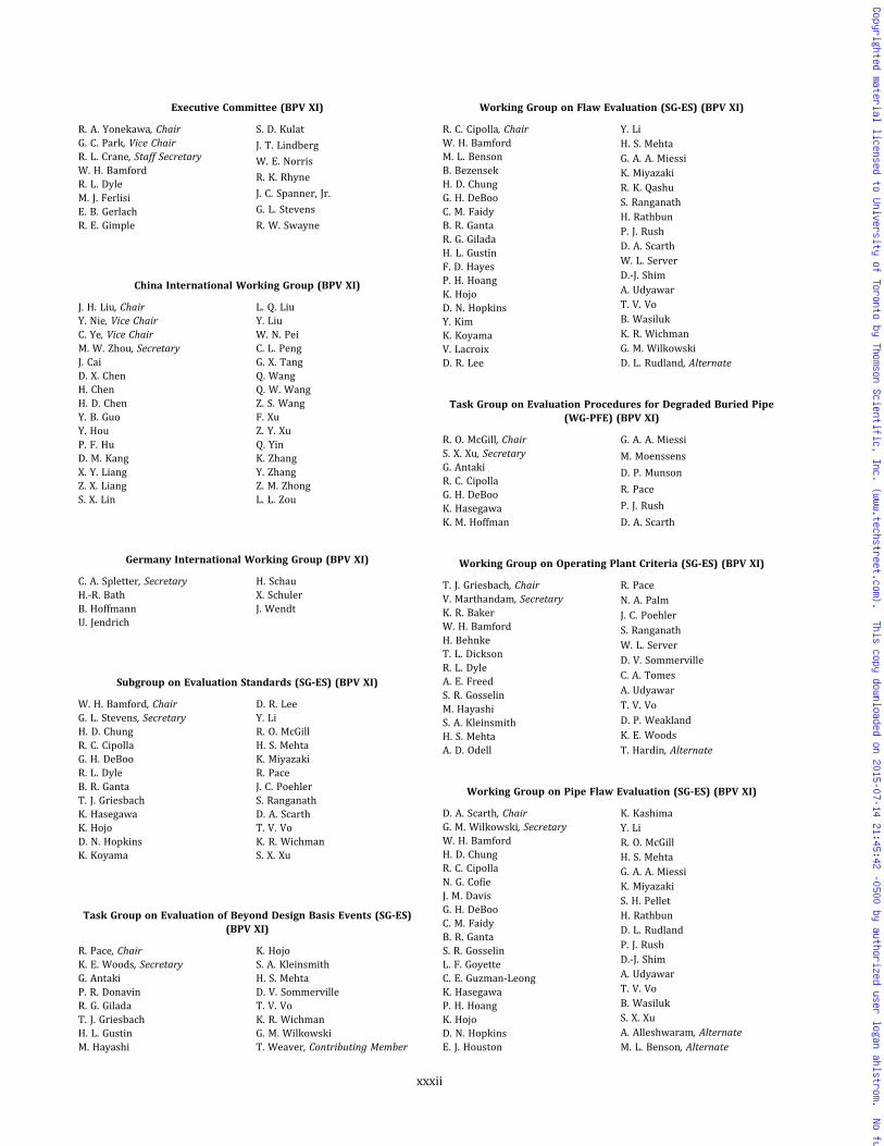
Executive Committee (BPV XI)
R. A. Yonekawa, ChairG. C. Park, Vice ChairR. L. Crane, Staff SecretaryW. H. BamfordR. L. DyleM. J. FerlisiE. B. GerlachR. E. Gimple
S. D. Kulat
J. T. Lindberg
W. E. Norris
R. K. Rhyne
J. C. Spanner, Jr.
G. L. Stevens
R. W. Swayne
China International Working Group (BPV XI)
J. H. Liu, ChairY. Nie, Vice ChairC. Ye, Vice ChairM. W. Zhou, SecretaryJ. CaiD. X. ChenH. ChenH. D. ChenY. B. GuoY. HouP. F. HuD. M. KangX. Y. LiangZ. X. LiangS. X. Lin
L. Q. LiuY. LiuW. N. PeiC. L. PengG. X. TangQ. WangQ. W. WangZ. S. WangF. XuZ. Y. XuQ. YinK. ZhangY. ZhangZ. M. ZhongL. L. Zou
Germany International Working Group (BPV XI)
C. A. Spletter, SecretaryH.-R. BathB. HoffmannU. Jendrich
H. SchauX. SchulerJ. Wendt
Subgroup on Evaluation Standards (SG-ES) (BPV XI)
W. H. Bamford, ChairG. L. Stevens, SecretaryH. D. ChungR. C. CipollaG. H. DeBooR. L. DyleB. R. GantaT. J. GriesbachK. HasegawaK. HojoD. N. HopkinsK. Koyama
D. R. LeeY. LiR. O. McGillH. S. MehtaK. MiyazakiR. PaceJ. C. PoehlerS. RanganathD. A. ScarthT. V. VoK. R. WichmanS. X. Xu
Task Group on Evaluation of Beyond Design Basis Events (SG-ES)(BPV XI)
R. Pace, ChairK. E. Woods, SecretaryG. AntakiP. R. DonavinR. G. GiladaT. J. GriesbachH. L. GustinM. Hayashi
K. HojoS. A. KleinsmithH. S. MehtaD. V. SommervilleT. V. VoK. R. WichmanG. M. WilkowskiT. Weaver, Contributing Member
Working Group on Flaw Evaluation (SG-ES) (BPV XI)
R. C. Cipolla, ChairW. H. BamfordM. L. BensonB. BezensekH. D. ChungG. H. DeBooC. M. FaidyB. R. GantaR. G. GiladaH. L. GustinF. D. HayesP. H. HoangK. HojoD. N. HopkinsY. KimK. KoyamaV. LacroixD. R. Lee
Y. LiH. S. MehtaG. A. A. MiessiK. MiyazakiR. K. QashuS. RanganathH. RathbunP. J. RushD. A. ScarthW. L. ServerD.-J. ShimA. UdyawarT. V. VoB. WasilukK. R. WichmanG. M. WilkowskiD. L. Rudland, Alternate
Task Group on Evaluation Procedures for Degraded Buried Pipe(WG-PFE) (BPV XI)
R. O. McGill, ChairS. X. Xu, SecretaryG. AntakiR. C. CipollaG. H. DeBooK. HasegawaK. M. Hoffman
G. A. A. Miessi
M. Moenssens
D. P. Munson
R. Pace
P. J. Rush
D. A. Scarth
Working Group on Operating Plant Criteria (SG-ES) (BPV XI)
T. J. Griesbach, ChairV. Marthandam, SecretaryK. R. BakerW. H. BamfordH. BehnkeT. L. DicksonR. L. DyleA. E. FreedS. R. GosselinM. HayashiS. A. KleinsmithH. S. MehtaA. D. Odell
R. PaceN. A. PalmJ. C. PoehlerS. RanganathW. L. ServerD. V. SommervilleC. A. TomesA. UdyawarT. V. VoD. P. WeaklandK. E. WoodsT. Hardin, Alternate
Working Group on Pipe Flaw Evaluation (SG-ES) (BPV XI)
D. A. Scarth, ChairG. M. Wilkowski, SecretaryW. H. BamfordH. D. ChungR. C. CipollaN. G. CofieJ. M. DavisG. H. DeBooC. M. FaidyB. R. GantaS. R. GosselinL. F. GoyetteC. E. Guzman-LeongK. HasegawaP. H. HoangK. HojoD. N. HopkinsE. J. Houston
K. KashimaY. LiR. O. McGillH. S. MehtaG. A. A. MiessiK. MiyazakiS. H. PelletH. RathbunD. L. RudlandP. J. RushD.-J. ShimA. UdyawarT. V. VoB. WasilukS. X. XuA. Alleshwaram, AlternateM. L. Benson, Alternate
xxxii
Copyrighted material licensed to University of Toronto by Thomson Scientific, Inc. (www.techstreet.com). This copy downloaded on 2015-07-14 21:45:42 -0500 by authorized user logan ahlstrom. No further reproduction or distribution is permitted.

Subgroup on Nondestructive Examination (SG-NDE) (BPV XI)
J. C. Spanner, Jr., ChairD. R. Cordes, SecretaryD. AlleyT. L. ChanC. B. CheezemF. E. DohmenD. O. Henry
J. T. LindbergG. A. LofthusG. R. PerkinsS. A. SaboF. J. Schaaf, Jr.R. V. SwainC. J. Wirtz
Working Group on Personnel Qualification and Surface Visual andEddy Current Examination (SG-NDE) (BPV XI)
J. T. Lindberg, ChairJ. E. Aycock, SecretaryS. E. CumblidgeA. DiazN. FarenbaughD. O. Henry
J. W. HoufJ. C. Spanner, Jr.J. T. TimmM. C. WeatherlyM. L. WhytsellC. J. Wirtz
Working Group on Procedure Qualification and VolumetricExamination (SG-NDE) (BPV XI)
G. A. Lofthus, ChairG. R. Perkins, SecretaryM. T. AndersonM. BrileyC. B. CheezemA. D. ChockieD. R. CordesM. DennisS. R. Doctor
F. E. DohmenK. J. HackerD. B. KingD. A. KullC. A. NoveS. A. SaboR. V. SwainS. J. ToddD. K. Zimmerman
Subgroup on Repair/Replacement Activities (SG-RRA) (BPV XI)
E. B. Gerlach, ChairE. V. Farrell, Jr., SecretaryJ. F. BallS. B. BrownR. E. CantrellR. ClowP. D. FisherR. E. GimpleD. R. GrahamR. A. HermannK. J. KarwoskiR. D. Kerr
S. L. McCracken
B. R. Newton
J. E. O'Sullivan
S. Schuessler
R. R. Stevenson
R. W. Swayne
D. L. Tilly
D. E. Waskey
J. G. Weicks
R. A. Yonekawa
E. G. Reichelt, Alternate
Working Group on Welding and Special Repair Processes (SG-RRA)(BPV XI)
D. E. Waskey, ChairD. J. Tilly, SecretaryR. E. CantrellS. J. FindlanP. D. FisherM. L. HallR. A. HermannK. J. Karwoski
C. C. Kim
S. L. McCracken
D. B. Meredith
B. R. Newton
J. E. O'Sullivan
R. E. Smith
J. G. Weicks
Working Group on Nonmetals Repair/Replacement Activities(SG-RRA) (BPV XI)
J. E. O'Sullivan, ChairS. Schuessler, SecretaryM. T. AudrainJ. Johnston, Jr.T. M. Musto
S. PattersonB. B. RajiF. J. Schaaf, Jr.Z. J. Zhou
Task Group on Repair by Carbon Fiber Composites(WGN-MRR) (BPV XI)
J. E. O'Sullivan, ChairJ. W. CollinsM. GollietL. S. GordonT. JimenezG. M. LupiaM. P. Marohl
R. P. OjdrovicD. PegueroA. PridmoreB. B. RajiC. W. RowleyV. RoyJ. Wen
Working Group on Design and Programs (SG-RRA) (BPV XI)
R. Clow, ChairA. B. Meichler, SecretaryO. BhattyS. B. BrownJ. W. CollinsL. R. CorrR. R. CroftE. V. Farrell, Jr.E. B. Gerlach
D. R. Graham
G. F. Harttraft
T. E. Hiss
H. Malikowski
M. A. Pyne
R. R. Stevenson
R. W. Swayne
R. A. Yonekawa
Subgroup on Water-Cooled Systems (SG-WCS) (BPV XI)
S. D. Kulat, ChairN. A. Palm, SecretaryJ. M. AgoldV. L. ArmentroutJ. M. BoughmanS. T. ChesworthA. D. CinsonD. D. DavisH. Q. DoE. L. Farrow
M. J. Ferlisi
P. J. Hennessey
D. W. Lamond
A. McNeill III
T. Nomura
G. C. Park
J. E. Staffiera
H. M. Stephens, Jr.
R. Turner
Task Group on High Strength Nickel Alloys Issues (SG-WCS) (BPV XI)
R. L. Dyle, ChairB. L. Montgomery, SecretaryW. H. BamfordP. R. DonavinR. E. GimpleR. HardiesK. KoyamaM. LashleyH. Malikowski
S. E. Marlette
G. C. Park
J. M. Shuping
J. C. Spanner, Jr.
K. B. Stuckey
E. J. Sullivan, Jr.
B. C. Thomas
D. P. Weakland
Working Group on Containment (SG-WCS) (BPV XI)
J. E. Staffiera, ChairH. M. Stephens, Jr., SecretaryP. S. GhosalH. T. HillR. D. HoughB. LehmanJ. A. Munshi
D. J. Naus
A. A. Reyes-Cruz
E. A. Rodriguez
M. Sircar
S. G. Brown, Alternate
T. J. Herrity, Alternate
xxxiii
Copyrighted material licensed to University of Toronto by Thomson Scientific, Inc. (www.techstreet.com). This copy downloaded on 2015-07-14 21:45:42 -0500 by authorized user logan ahlstrom. No further reproduction or distribution is permitted.

Working Group on Inspection of Systems and Components(SG-WCS) (BPV XI)
J. M. Agold, ChairN. Granback, SecretaryR. W. BlydeC. Cueto-FelguerosoR. E. DayH. Q. DoM. J. FerlisiK. W. Hall
K. M. Hoffman
S. D. Kulat
A. Lee
T. Nomura
J. C. Nygaard
R. Rishel
G. J. Navratil, Alternate
Task Group on Optimization of Ultrasonic Evaluation Requirements(WG-ISC) (BPV XI)
M. J. Ferlisi, ChairK. W. HallD. O. HenryK. M. Hoffman
B. L. MontgomeryG. J. NavratilM. OrihuelaJ. C. Poehler
Working Group on Pressure Testing (SG-WCS) (BPV XI)
D. W. Lamond, ChairJ. M. Boughman, SecretaryD. AlleyY.-K. ChungJ. A. Doughty
R. E. HallA. E. KeyserJ. K. McClanahanB. L. MontgomeryS. A. Norman
Task Group on Buried Components Inspection and Testing(WG-PT) (BPV XI)
D. W. Lamond, ChairJ. M. Boughman, SecretaryM. Moenssens, SecretaryC. BlackwelderG. C. CokerR. E. DayR. Hardies
T. Ivy
A. Lee
G. M. Lupia
J. Ossmann
M. A. Richter
D. Smith
Working Group on Risk-Informed Activities (SG-WCS) (BPV XI)
M. A. Pyne, ChairS. T. Chesworth, SecretaryJ. M. AgoldC. Cueto-FelguerosoH. Q. DoR. FougerousseM. R. GraybealR. HaesslerJ. HakiiK. W. Hall
K. M. Hoffman
S. D. Kulat
D. W. Lamond
R. K. Mattu
A. McNeill III
P. J. O’ReganN. A. Palm
D. Vetter
J. C. Younger
Special Working Group on Editing and Review (BPV XI)
R. W. Swayne, ChairC. E. MoyerK. R. Rao
J. E. StaffieraD. J. TillyC. J. Wirtz
Special Working Group on Nuclear Plant Aging Management(BPV XI)
B. R. Snyder, ChairA. B. Meichler, SecretaryT. M. AnselmiS. AsadaD. V. BurgessY.-K. ChungD. D. DavisR. L. Dyle
A. L. Hiser, Jr.R. E. NickellK. SakamotoW. L. ServerR. L. TurnerG. G. YoungZ. ZhongM. Srinivasan, Alternate
Working Group on General Requirements (BPV XI)
R. K. Rhyne, ChairE. J. Maloney, SecretaryJ. F. BallT. L. ChanE. L. Farrow
P. J. HennesseyK. M. HermanR. K. MattuC. E. MoyerR. L. Williams
Special Working Group on Reliability and Integrity ManagementProgram (BPV XI)
F. J. Schaaf, Jr., ChairA. T. Roberts III, SecretaryN. BroomS. R. DoctorJ. FletcherS. R. GosselinN. GranbackJ. GrimmA. B. Hull
D. M. JonesA. L. KrinzmanD. R. LeeR. K. MillerM. N. MitchellR. MorrillT. RoneyR. W. SwayneS. Takaya
JSME/ASME Joint Task Group for System-Based Code (SWG-RIM)(BPV XI)
T. Asayama, ChairK. DozakiM. R. GraybealM. HayashiY. Kamishima
H. MachidaM. MorishitaF. J. Schaaf, Jr.S. TakayaD. Watanabe
COMMITTEE ON TRANSPORT TANKS (BPV XII)
M. D. Rana, ChairN. J. Paulick, Vice ChairT. Schellens, Staff SecretaryA. N. AntoniouP. ChilukuriW. L. GarfieldG. G. KarcherM. Pitts
T. A. RogersS. StaniszewskiA. P. VargheseM. R. WardJ. A. Byers, Contributing MemberR. Meyers, Contributing MemberM. D. Pham, Contributing MemberA. Selz, Contributing Member
Subgroup on Design and Materials (BPV XII)
A. P. Varghese, ChairR. C. Sallash, SecretaryD. K. ChandiramaniP. ChilukuriG. G. KarcherS. L. McWilliamsN. J. PaulickM. D. Rana
T. A. Rogers
A. Selz
M. R. Ward
K. Xu
J. Zheng, Corresponding Member
T. Hitchcock, Contributing Member
M. D. Pham, Contributing Member
xxxiv
Copyrighted material licensed to University of Toronto by Thomson Scientific, Inc. (www.techstreet.com). This copy downloaded on 2015-07-14 21:45:42 -0500 by authorized user logan ahlstrom. No further reproduction or distribution is permitted.
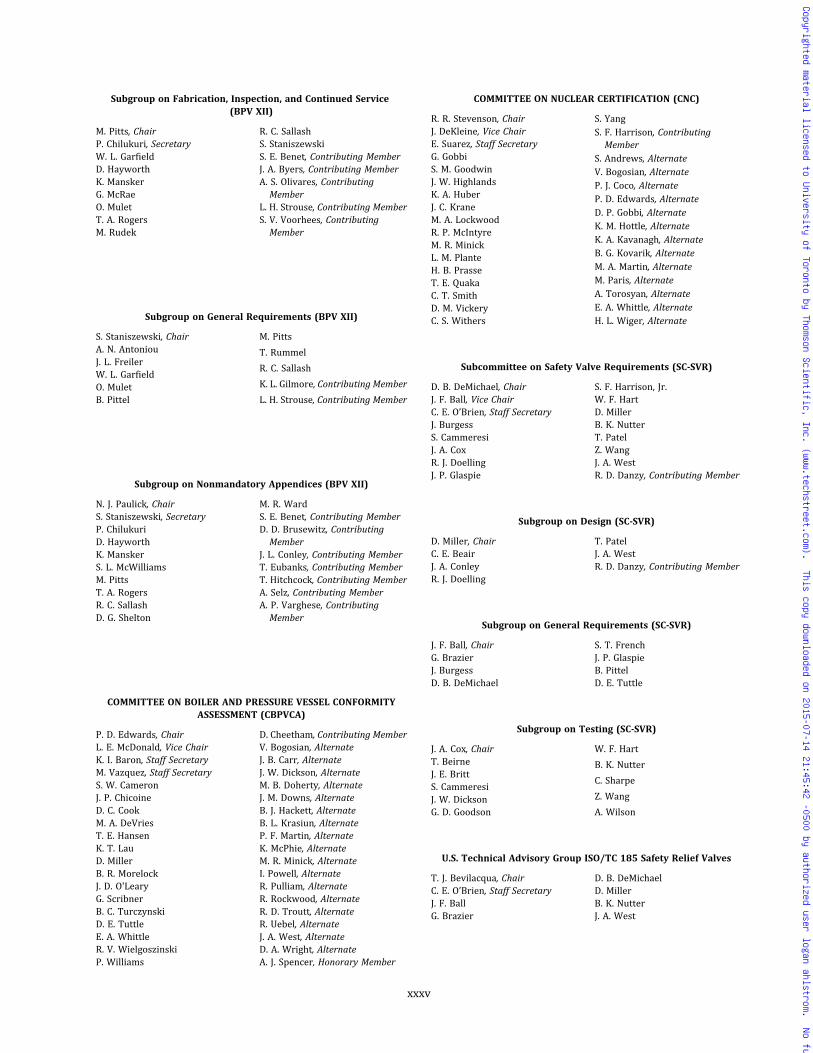
Subgroup on Fabrication, Inspection, and Continued Service(BPV XII)
M. Pitts, ChairP. Chilukuri, SecretaryW. L. GarfieldD. HayworthK. ManskerG. McRaeO. MuletT. A. RogersM. Rudek
R. C. SallashS. StaniszewskiS. E. Benet, Contributing MemberJ. A. Byers, Contributing MemberA. S. Olivares, ContributingMember
L. H. Strouse, Contributing MemberS. V. Voorhees, ContributingMember
Subgroup on General Requirements (BPV XII)
S. Staniszewski, ChairA. N. AntoniouJ. L. FreilerW. L. GarfieldO. MuletB. Pittel
M. Pitts
T. Rummel
R. C. Sallash
K. L. Gilmore, Contributing Member
L. H. Strouse, Contributing Member
Subgroup on Nonmandatory Appendices (BPV XII)
N. J. Paulick, ChairS. Staniszewski, SecretaryP. ChilukuriD. HayworthK. ManskerS. L. McWilliamsM. PittsT. A. RogersR. C. SallashD. G. Shelton
M. R. WardS. E. Benet, Contributing MemberD. D. Brusewitz, ContributingMember
J. L. Conley, Contributing MemberT. Eubanks, Contributing MemberT. Hitchcock, Contributing MemberA. Selz, Contributing MemberA. P. Varghese, ContributingMember
COMMITTEE ON BOILER AND PRESSURE VESSEL CONFORMITYASSESSMENT (CBPVCA)
P. D. Edwards, ChairL. E. McDonald, Vice ChairK. I. Baron, Staff SecretaryM. Vazquez, Staff SecretaryS. W. CameronJ. P. ChicoineD. C. CookM. A. DeVriesT. E. HansenK. T. LauD. MillerB. R. MorelockJ. D. O'LearyG. ScribnerB. C. TurczynskiD. E. TuttleE. A. WhittleR. V. WielgoszinskiP. Williams
D. Cheetham, Contributing MemberV. Bogosian, AlternateJ. B. Carr, AlternateJ. W. Dickson, AlternateM. B. Doherty, AlternateJ. M. Downs, AlternateB. J. Hackett, AlternateB. L. Krasiun, AlternateP. F. Martin, AlternateK. McPhie, AlternateM. R. Minick, AlternateI. Powell, AlternateR. Pulliam, AlternateR. Rockwood, AlternateR. D. Troutt, AlternateR. Uebel, AlternateJ. A. West, AlternateD. A. Wright, AlternateA. J. Spencer, Honorary Member
COMMITTEE ON NUCLEAR CERTIFICATION (CNC)
R. R. Stevenson, ChairJ. DeKleine, Vice ChairE. Suarez, Staff SecretaryG. GobbiS. M. GoodwinJ. W. HighlandsK. A. HuberJ. C. KraneM. A. LockwoodR. P. McIntyreM. R. MinickL. M. PlanteH. B. PrasseT. E. QuakaC. T. SmithD. M. VickeryC. S. Withers
S. YangS. F. Harrison, ContributingMember
S. Andrews, AlternateV. Bogosian, AlternateP. J. Coco, AlternateP. D. Edwards, AlternateD. P. Gobbi, AlternateK. M. Hottle, AlternateK. A. Kavanagh, AlternateB. G. Kovarik, AlternateM. A. Martin, AlternateM. Paris, AlternateA. Torosyan, AlternateE. A. Whittle, AlternateH. L. Wiger, Alternate
Subcommittee on Safety Valve Requirements (SC-SVR)
D. B. DeMichael, ChairJ. F. Ball, Vice ChairC. E. O’Brien, Staff SecretaryJ. BurgessS. CammeresiJ. A. CoxR. J. DoellingJ. P. Glaspie
S. F. Harrison, Jr.W. F. HartD. MillerB. K. NutterT. PatelZ. WangJ. A. WestR. D. Danzy, Contributing Member
Subgroup on Design (SC-SVR)
D. Miller, ChairC. E. BeairJ. A. ConleyR. J. Doelling
T. PatelJ. A. WestR. D. Danzy, Contributing Member
Subgroup on General Requirements (SC-SVR)
J. F. Ball, ChairG. BrazierJ. BurgessD. B. DeMichael
S. T. FrenchJ. P. GlaspieB. PittelD. E. Tuttle
Subgroup on Testing (SC-SVR)
J. A. Cox, ChairT. BeirneJ. E. BrittS. CammeresiJ. W. DicksonG. D. Goodson
W. F. Hart
B. K. Nutter
C. Sharpe
Z. Wang
A. Wilson
U.S. Technical Advisory Group ISO/TC 185 Safety Relief Valves
T. J. Bevilacqua, ChairC. E. O’Brien, Staff SecretaryJ. F. BallG. Brazier
D. B. DeMichaelD. MillerB. K. NutterJ. A. West
xxxv
Copyrighted material licensed to University of Toronto by Thomson Scientific, Inc. (www.techstreet.com). This copy downloaded on 2015-07-14 21:45:42 -0500 by authorized user logan ahlstrom. No further reproduction or distribution is permitted.
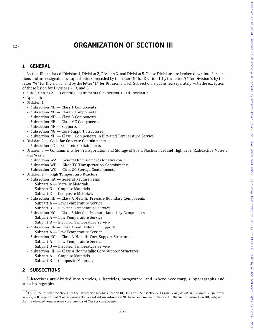
ð15Þ ORGANIZATION OF SECTION III
1 GENERAL
Section III consists of Division 1, Division 2, Division 3, and Division 5. These Divisions are broken down into Subsec-tions and are designated by capital letters preceded by the letter “N” for Division 1, by the letter “C” for Division 2, by theletter “W” for Division 3, and by the letter “H” for Division 5. Each Subsection is published separately, with the exceptionof those listed for Divisions 2, 3, and 5.• Subsection NCA — General Requirements for Division 1 and Division 2• Appendices• Division 1
– Subsection NB — Class 1 Components– Subsection NC — Class 2 Components– Subsection ND — Class 3 Components– Subsection NE — Class MC Components– Subsection NF — Supports– Subsection NG — Core Support Structures– Subsection NH — Class 1 Components in Elevated Temperature Service*
• Division 2 — Code for Concrete Containments– Subsection CC — Concrete Containments
• Division 3 — Containments for Transportation and Storage of Spent Nuclear Fuel and High Level Radioactive Materialand Waste– Subsection WA — General Requirements for Division 3– Subsection WB — Class TC Transportation Containments– Subsection WC — Class SC Storage Containments
• Division 5 — High Temperature Reactors– Subsection HA — General Requirements
Subpart A — Metallic MaterialsSubpart B — Graphite MaterialsSubpart C — Composite Materials
– Subsection HB — Class A Metallic Pressure Boundary ComponentsSubpart A — Low Temperature ServiceSubpart B — Elevated Temperature Service
– Subsection HC — Class B Metallic Pressure Boundary ComponentsSubpart A — Low Temperature ServiceSubpart B — Elevated Temperature Service
– Subsection HF — Class A and B Metallic SupportsSubpart A — Low Temperature Service
– Subsection HG — Class A Metallic Core Support StructuresSubpart A — Low Temperature ServiceSubpart B — Elevated Temperature Service
– Subsection HH — Class A Nonmetallic Core Support StructuresSubpart A — Graphite MaterialsSubpart B — Composite Materials
2 SUBSECTIONS
Subsections are divided into Articles, subarticles, paragraphs, and, where necessary, subparagraphs andsubsubparagraphs.
* The 2015 Edition of Section III is the last edition in which Section III, Division 1, Subsection NH, Class 1 Components in Elevated TemperatureService, will be published. The requirements located within Subsection NH have been moved to Section III, Division 5, Subsection HB, Subpart Bfor the elevated temperature construction of Class A components.
xxxvi
Copyrighted material licensed to University of Toronto by Thomson Scientific, Inc. (www.techstreet.com). This copy downloaded on 2015-07-14 21:45:42 -0500 by authorized user logan ahlstrom. No further reproduction or distribution is permitted.

3 ARTICLES
Articles are designated by the applicable letters indicated above for the Subsections followed by Arabic numbers, suchas NB-1000. Where possible, Articles dealing with the same topics are given the same number in each Subsection, exceptNCA, in accordance with the following general scheme:
Article Number Title
1000 Introduction or Scope2000 Material3000 Design4000 Fabrication and Installation5000 Examination6000 Testing7000 Overpressure Protection8000 Nameplates, StampingWith Certification Mark, and Reports
The numbering of Articles and the material contained in the Articles may not, however, be consecutive. Due to the factthat the complete outline may cover phases not applicable to a particular Subsection or Article, the rules have been pre-pared with some gaps in the numbering.
4 SUBARTICLES
Subarticles are numbered in units of 100, such as NB-1100.
5 SUBSUBARTICLES
Subsubarticles are numbered in units of 10, such as NB-2130, and generally have no text. When a number such asNB-1110 is followed by text, it is considered a paragraph.
6 PARAGRAPHS
Paragraphs are numbered in units of 1, such as NB-2121.
7 SUBPARAGRAPHS
Subparagraphs, when they aremajor subdivisions of a paragraph, are designated by adding a decimal followed by oneor more digits to the paragraph number, such as NB-1132.1. When they are minor subdivisions of a paragraph, subpar-agraphs may be designated by lowercase letters in parentheses, such as NB-2121(a).
8 SUBSUBPARAGRAPHS
Subsubparagraphs are designated by adding lowercase letters in parentheses to the major subparagraph numbers,such as NB-1132.1(a). When further subdivisions of minor subparagraphs are necessary, subsubparagraphs are desig-nated by adding Arabic numerals in parentheses to the subparagraph designation, such as NB-2121(a)(1).
9 REFERENCES
References used within Section III generally fall into one of the following four categories:(a) References to Other Portions of Section III.When a reference is made to another Article, subarticle, or paragraph, all
numbers subsidiary to that reference shall be included. For example, reference to NB-3000 includes all material inArticle NB-3000; reference to NB-3200 includes all material in subarticle NB-3200; reference to NB-3230 includes allparagraphs, NB-3231 through NB-3236.
(b) References to Other Sections. Other Sections referred to in Section III are the following:(1) Section II, Materials.When a requirement for a material, or for the examination or testing of a material, is to be in
accordance with a specification such as SA-105, SA-370, or SB-160, the reference is to material specifications inSection II. These references begin with the letter “S.”
xxxvii
Copyrighted material licensed to University of Toronto by Thomson Scientific, Inc. (www.techstreet.com). This copy downloaded on 2015-07-14 21:45:42 -0500 by authorized user logan ahlstrom. No further reproduction or distribution is permitted.
(2) Section V, Nondestructive Examination. Section V references begin with the letter “T” and relate to the nondes-tructive examination of material or welds.
(3) Section IX, Welding and Brazing Qualifications. Section IX references begin with the letter “Q” and relate to weld-ing and brazing requirements.
(4) Section XI, Rules for Inservice Inspection of Nuclear Power Plant Components. When a reference is made to inser-vice inspection, the rules of Section XI shall apply.
(c) Reference to Specifications and Standards Other Than Published in Code Sections
(1) Specifications for examination methods and acceptance standards to be used in connection with them are pub-lished by the American Society for Testing and Materials (ASTM). At the time of publication of Section III, some suchspecifications were not included in Section II of this Code. A reference to ASTM E94 refers to the specification so desig-nated by and published by ASTM, 100 Barr Harbor Drive, West Conshohocken, PA 19428.
(2) Dimensional standards covering products such as valves, flanges, and fittings are sponsored and published byThe American Society of Mechanical Engineers and approved by the American National Standards Institute.** When aproduct is to conform to such a standard, for example ASME B16.5, the standard is approved by the American NationalStandards Institute. The applicable year of issue is that suffixed to its numerical designation in Table NCA-7100-1, forexample ASME B16.5-2003. Standards published by The American Society of Mechanical Engineers are available fromASME (https://www.asme.org/).
(3) Dimensional and other types of standards covering products such as valves, flanges, and fittings are also pub-lished by the Manufacturers Standardization Society of the Valve and Fittings Industry and are known as Standard Prac-tices. When a product is required by these rules to conform to a Standard Practice, for example MSS SP-100, the StandardPractice referred to is published by the Manufacturers Standardization Society of the Valve and Fittings Industry, Inc.(MSS), 127 Park Street, NE, Vienna, VA 22180. The applicable year of issue of such a Standard Practice is that suffixedto its numerical designation in Table NCA-7100-1, for example MSS SP-89-2003.
(4) Specifications for welding and brazing materials are published by the American Welding Society (AWS), 8669Doral Boulevard, Suite 130, Doral, FL 33166. Specifications of this type are incorporated in Section II and are identifiedby the AWS designation with the prefix “SF,” for example SFA-5.1.
(5) Standards applicable to the design and construction of tanks and flanges are published by the American Petro-leum Institute and have designations such as API-605. When documents so designated are referred to in Section III, forexample API-605–1988, they are standards published by the American Petroleum Institute and are listed in TableNCA-7100-1.
(d) References to Appendices. Section III uses two types of appendices that are designated as either Section III Appen-dices or Subsection Appendices. Either of these appendices is further designated as either Mandatory or Nonmandatoryfor use. Mandatory Appendices are referred to in the Section III rules and contain requirements that must be followed inconstruction. Nonmandatory Appendices provide additional information or guidance when using Section III.
(1) Section III Appendices are contained in a separate book titled "Appendices." These appendices have the potentialfor multiple subsection applicability. Mandatory Appendices are designated by a Roman numeral followed, when appro-priate, by Arabic numerals to indicate various articles, subarticles, and paragraphs of the appendix, such as II-1500 orXIII-2131. Nonmandatory Appendices are designated by a capital letter followed, when appropriate, by Arabic numeralsto indicate various articles, subarticles, and paragraphs of the appendix, such as D-1200 or Y-1440.
(2) Subsection Appendices are specifically applicable to just one subsection and are contained within that subsec-tion. Subsection-specific mandatory and nonmandatory appendices are numbered in the same manner as Section III Ap-pendices, but with a subsection identifier (e.g., NF, NH, D2, etc.) preceding either the Roman numeral or the capital letterfor a unique designation. For example, NF-II-1100 or NF-A-1200 would be part of a Subsection NF mandatory or non-mandatory appendix, respectively. For Subsection CC, D2-IV-1120 or D2-D-1330 would be part of a Subsection CC man-datory or nonmandatory appendix, respectively.
(3) It is the intent of this Section that the information provided in both Mandatory and Nonmandatory Appendicesmay be used to meet the rules of any Division or Subsection. In case of conflict between Appendix rules and Division/Subsection rules, the requirements contained in the Division/Subsection shall govern. Additional guidance on Appendixusage is provided in the front matter of Section III Appendices.
** The American National Standards Institute (ANSI) was formerly known as the American Standards Association. Standards approved by theAssociation were designated by the prefix “ASA” followed by the number of the standard and the year of publication. More recently, the Amer-ican National Standards Institute was known as the United States of America Standards Institute. Standards were designated by the prefix“USAS” followed by the number of the standard and the year of publication. While the letters of the prefix have changed with the name ofthe organization, the numbers of the standards have remained unchanged.
xxxviii
Copyrighted material licensed to University of Toronto by Thomson Scientific, Inc. (www.techstreet.com). This copy downloaded on 2015-07-14 21:45:42 -0500 by authorized user logan ahlstrom. No further reproduction or distribution is permitted.

SUMMARY OF CHANGES
After publication of the 2015 Edition, Errata to the BPV Code may be posted on the ASMEWeb site to provide correctionsto incorrectly published items, or to correct typographical or grammatical errors in the BPV Code. Such Errata shall beused on the date posted.
Information regarding Special Notices and Errata is published by ASME at http://go.asme.org/BPVCerrata.
Changes given below are identified on the pages by a margin note, (15), placed next to the affected area.
The Record Numbers listed below are explained in more detail in “List of Changes in Record Number Order” followingthis Summary of Changes.
Page Location Change (Record Number)
xii List of Sections Revised
xiv Foreword (1) Revised(2) New footnote added by errata (13-860)
xvii Submittal of TechnicalInquiries to the Boilerand Pressure VesselStandards Committees
In last line of 6(a), URL revised
xix Personnel Updated
xxxvi Organization of Section III (1) New footnote added(2) 9(d)(3) added (13-1032)
6 WA-3320 Subparagraph (g)(2) deleted and subsequent subparagraphsredesignated (14-1494)
15 WA-5300 Subparagraph (i) revised (14-1494)
17 Table WA-7100-2 Third column, third entry revised (12-454)
39 WB-2420 In first paragraph, cross-reference to Section IX revised (14-1494)
54 WB-3111 Subparagraph (g) revised (13-2298)
54 WB-3112.4 In second line of subpara. (a)(2), “and” corrected by errata to “or”(13-1956)
55 WB-3133 Title revised (13-2298)
55 WB-3133.1 Revised (13-2298)
56 WB-3133.3 Subparagraph (a) Step 2 revised (13-2298)
57 WB-3133.4 (1) Subparagraph (a) Step 2 revised (13-2298)(2) Subparagraph (b) revised (13-2298)
58 WB-3133.5 Subparagraph (a) Step 1 revised (13-2298)
58 WB-3133.6 Subparagraph (b) revised (13-2298)
59 WB-3135 Subparagraph (a) revised (13-2298)
59 WB-3213.2 Revised (13-2298)
61 WB-3213.18 Deleted (06-1236)
61 WB-3213.19 Deleted (06-1236)
xxxix
Copyrighted material licensed to University of Toronto by Thomson Scientific, Inc. (www.techstreet.com). This copy downloaded on 2015-07-14 21:45:42 -0500 by authorized user logan ahlstrom. No further reproduction or distribution is permitted.
Page Location Change (Record Number)
61 WB-3215 (1) Subparagraph (b)(4) deleted and subsequent subparagraphsredesignated (06-1236, 13–2298)
(2) In endnote 18, “and” corrected by errata to “or” (14-599)
63 Table WB-3217-1 Entry in penultimate row and column revised (13-2298)
65 Figure WB-3221-1 Revised (06-1236)
62 WB-3221.1 Revised (13-2298)
62 WB-3221.4 Revised (06-1236)
66 Figure WB-3222-1 Revised (06-1236)
64 WB-3222.4 Revised (06-1236)
64 WB-3222.6 Revised (06-1236)
64 WB-3222.7 Deleted (06-1236)
67 WB-3222.9 Subparagraphs (a), (d), (d)(2), (d)(3), and Note revised (13-2298)
69 WB-3224.1 Subparagraph (c) revised (06-1236)
70 Figure WB-3224.1-1 Revised (06-1236)
72 WB-3231 Revised (12-1105)
72 WB-3232.1 Revised (12-1105)
72 WB-3232.2 Revised (12-1105)
72 WB-3232.3 Revised (12-1105)
73 WB-3232.4 (1) Revised (13-2298)(2) Subparagraph (b)(1) revised (12-1105)(3) Subparagraph (d) revised (13-2298)
73 WB-3236 Revised (13-2298)
73 WB-3240 Subparagraph (b) revised (06-1236)
74 WB-3252.2 Revised (13-2298)
76 WB-3252.4 Subparagraphs (c), (d), and (f)(2) revised (13–2298)
77 WB-3700 Subparagraphs (c), (d), and (f)(2) revised (13–1955)
92 WB-4324 Revised (14-1494)
97 WB-4453.4 In subparagraph (b)(2), “Article 5” corrected by errata to “Article 4”(13-1270)
113 WB-5245 Revised (14-1494)
115 WB-5521 Subparagraphs (a), (a)(3), and (a)(4) revised (12-454)
125 WC-2150 Revised (14-45)
132 WC-2420 Revised (14-1494)
134 WC-2432.1 Subparagraph (d) revised (14-1494)
143 WC-3112.4 In subparagraph (b), “and” corrected by errata to “or” (13-1956)
147 WC-3211.1 Subparagraph (c) revised (14-600)
147 WC-3211.3 Revised (14-600)
152 WC-3224.3 Subparagraph (c) revised (14-600)
xl
Copyrighted material licensed to University of Toronto by Thomson Scientific, Inc. (www.techstreet.com). This copy downloaded on 2015-07-14 21:45:42 -0500 by authorized user logan ahlstrom. No further reproduction or distribution is permitted.
Page Location Change (Record Number)
152 WC-3224.4 Subparagraph (c) revised (14-600)
157 Figure WC-3225-3 In sketch (e),Tand c relocated by errata for clarity (14-599, 14–600)
154 WC-3231 Subparagraph (a) revised (14-1494)
156 WC-3233 Revised (14-600)
160 WC-3252.4 Subparagraphs (a), (b), and (d) revised (14-600)
161 WC-3259 Subparagraph (b) revised (14-600)
162 WC-3700 Revised (13-1955)
172 WC-4324 Revised (14-1494)
181 WC-4453.4 In subpara. (b)(2), “Article V” corrected by errata to “Article 4”(13-1270)
191 Figure WC-4622.10(f)-1 Editorially revised
201 WC-5521 Subparagraphs (a), (a)(3), and (a)(4) revised (12-454)
NOTE: Volume 63 of the Interpretations to Section III, Division 3 of the ASME Boiler and Pressure Vessel Code followsthe last page of Section III, Division 3.
xli
Copyrighted material licensed to University of Toronto by Thomson Scientific, Inc. (www.techstreet.com). This copy downloaded on 2015-07-14 21:45:42 -0500 by authorized user logan ahlstrom. No further reproduction or distribution is permitted.

LIST OF CHANGES IN RECORD ORDER NUMBER
Record Number Change
06-1236 Revised Article WB-3000 to delete expansion stress (Pe) requirements, associated references,and assure correct wording for definitions of stress limits in the text and associated Hopperdiagrams.
12-454 Incorporated acceptance of the ASNT SNT-TC-1A 2011 standard into WB-5500, WC-5500, andWA-7100-2. Clarified the requirement for the near-vision acuity examination.
12-1105 Revised WB-3230 to utilize Sy for service stresses to account for the revised criteria for Sm val-ues for bolting.
13-860 In the Foreword, the subtitle has been deleted and replaced with an ANSI disclaimer as a foot-note.
13-1032 Added a paragraph to the introduction of Section III, Division 1, Organization of Section III,Article 9(d) References to Appendices to add guidance on the use of nonmandatory appendicesfor Section III.
13-1270 Revised the Section V Article callout to identify the proper Article for appropriate procedures toperform ultrasonic examination of repair welds.
13-1955 Eliminated weight limitations in WB-3700 and revised both WB-3700 and WC-3700 to showthat a strain-based acceptance criterion applies to components subject to energy-limitedevents.
13-1956 Revised WB/WC-3112.4 to read “SA-874 or SA/JIS G5504” in lieu of “SA-874 and SA/JISG5504.”
13-2298 Made editorial changes to Article WB-3000. These changes included replacing missing/incor-rect words, making the language consistent, and correcting references.
14-45 In WC-2150 corrected reference from NCA-3865 to NCA-3856.14-599 Corrected the errata identified in Articles WB-3000 and WC-3000.14-600 Corrected the various portions of Article WC-3000 with the editorial actions identified in the
proposal.14-1494 Updated and corrected nine cross references that either did not exist or were incorrect.
xlii
Copyrighted material licensed to University of Toronto by Thomson Scientific, Inc. (www.techstreet.com). This copy downloaded on 2015-07-14 21:45:42 -0500 by authorized user logan ahlstrom. No further reproduction or distribution is permitted.

CROSS-REFERENCING AND STYLISTIC CHANGES IN THE BOILERAND PRESSURE VESSEL CODE
There have been structural and stylistic changes to BPVC, starting with the 2011 Addenda, that should be noted to aidnavigating the contents. The following is an overview of the changes:
Subparagraph Breakdowns/Nested Lists Hierarchy
• First-level breakdowns are designated as (a), (b), (c), etc., as in the past.• Second-level breakdowns are designated as (1), (2), (3), etc., as in the past.• Third-level breakdowns are now designated as (-a), (-b), (-c), etc.• Fourth-level breakdowns are now designated as (-1), (-2), (-3), etc.• Fifth-level breakdowns are now designated as (+a), (+b), (+c), etc.• Sixth-level breakdowns are now designated as (+1), (+2), etc.
Footnotes
With the exception of those included in the front matter (roman-numbered pages), all footnotes are treated as end-notes. The endnotes are referenced in numeric order and appear at the end of each BPVC section/subsection.
Submittal of Technical Inquiries to the Boiler and Pressure Vessel Standards Committees
Submittal of Technical Inquiries to the Boiler and Pressure Vessel Standards Committees has been moved to the frontmatter. This information now appears in all Boiler Code Sections (except for Code Case books).
Cross-References
It is our intention to establish cross-reference link functionality in the current edition and moving forward. To facil-itate this, cross-reference style has changed. Cross-references within a subsection or subarticle will not include the des-ignator/identifier of that subsection/subarticle. Examples follow:
• (Sub-)Paragraph Cross-References. The cross-references to subparagraph breakdowns will follow the hierarchy ofthe designators under which the breakdown appears.– If subparagraph (-a) appears in X.1(c)(1) and is referenced in X.1(c)(1), it will be referenced as (-a).– If subparagraph (-a) appears in X.1(c)(1) but is referenced in X.1(c)(2), it will be referenced as (1)(-a).– If subparagraph (-a) appears in X.1(c)(1) but is referenced in X.1(e)(1), it will be referenced as (c)(1)(-a).– If subparagraph (-a) appears in X.1(c)(1) but is referenced in X.2(c)(2), it will be referenced as X.1(c)(1)(-a).
• Equation Cross-References. The cross-references to equations will follow the same logic. For example, if eq. (1) ap-pears in X.1(a)(1) but is referenced in X.1(b), it will be referenced as eq. (a)(1)(1). If eq. (1) appears in X.1(a)(1) butis referenced in a different subsection/subarticle/paragraph, it will be referenced as eq. X.1(a)(1)(1).
xliii
Copyrighted material licensed to University of Toronto by Thomson Scientific, Inc. (www.techstreet.com). This copy downloaded on 2015-07-14 21:45:42 -0500 by authorized user logan ahlstrom. No further reproduction or distribution is permitted.

INTENTIONALLY LEFT BLANK
Copyrighted material licensed to University of Toronto by Thomson Scientific, Inc. (www.techstreet.com). This copy downloaded on 2015-07-14 21:45:42 -0500 by authorized user logan ahlstrom. No further reproduction or distribution is permitted.
SUBSECTION WAGENERAL REQUIREMENTS
ARTICLE WA-1000SCOPE OF DIVISION 3
WA-1100 SCOPE
WA-1110 NATURE OF THESE RULES ANDCONTAINMENTS TO WHICH THEY AREAPPLICABLE
The rules of this Division constitute requirements forthe construction of:
(a) Containments used for the transportation and sto-rage, including disposal1 of spent nuclear fuel and highlevel radioactive material and waste, and
(b) Structures internal to the containment2 necessaryto support and maintain geometric configuration of thespent nuclear fuels and high level radioactive materialsand waste.
WA-1120 DEFINITIONS
Definitions of key terms used in this Division are in-cluded in Article WA-9000.
WA-1130 LIMITS OF THESE RULES
(a) The rules of this Division provide requirements fornew construction including consideration of mechanicaland thermal stresses due to cyclic operation. They donot cover deterioration which may occur in service as aresult of radiation effects, corrosion, erosion, or instabil-ity of the material. These effects shall be addressed inthe Design Specification by requiring appropriate mea-sures to be included in the design.
(b) The rules are intended to be applicable to any itemthat serves a containment or internal support2 function.
WA-1140 USE OF CODE EDITIONS, ADDENDA,AND CASES
(a) The Design Specification shall establish the CodeEdition and Addenda.
(b) The Certificate Holder shall construct the contain-ment under the provisions of a Quality Assurance Pro-gram which has been accepted by the Society. The
Quality Assurance Program shall be updated to meet therequirements of the latest Division 3 Edition and Addendawithin 6 months of issuance.
(c) Code Cases are permissible and may be used begin-ning with the date of approval by the ASME Council. OnlyCode Cases that are specifically identified as being applic-able to this Division may be used. Code Cases may only beused by mutual consent of the parties involved.
(d)Materials produced and certified in accordance withCode Editions and Addenda other than the one specifiedin the Design Specification may be used, provided all ofthe following requirements are satisfied.
(1) The material (WA-1220) meets the applicable re-quirements of a material specification permitted byWB-2121, WC-2121 of the Edition and Addenda specifiedfor construction.
(2) The material meets all the requirements ofWB-2000, WC-2000 of the Edition and Addenda specifiedfor construction.
(3) The material was produced under the provisionsof a Quality System Program which had been accepted bythe Society or qualified by a party other than the Society(NCA‐3820), in accordance with the requirements of thelatest Edition and Addenda issued at the time the materialwas produced. Material exempted from portions of theprovisions of NCA‐3800 by WB-2610, WC-2610 may beused, provided the requirements of (1) and (2) aboveare met.
WA-1150 UNITS OF MEASURE
Either U.S. Customary or SI units may be used for com-pliance with all requirements of this edition, but one sys-tem shall be used consistently throughout for all phases ofconstruction.
Either the U.S. Customary units or SI units that arelisted in Section III Appendices, Mandatory AppendixXXIV shall be used consistently for all phases of construc-tion (e.g., materials, design, fabrication, and reports).
1
ASME BPVC.III.3-2015
Copyrighted material licensed to University of Toronto by Thomson Scientific, Inc. (www.techstreet.com). This copy downloaded on 2015-07-14 21:45:42 -0500 by authorized user logan ahlstrom. No further reproduction or distribution is permitted.
Since values in the two systems are not exact equivalents,each system shall be used independently of the otherwithout mixing U.S. Customary units and SI units.When SI units are selected, U.S. Customary values in re-
ferenced specifications that do not contain SI units shallbe converted to SI values to at least three significantfigures for use in calculations and other aspects ofconstruction.With the publication of the 2004 Edition, Section II,
Part D is published as two separate publications. One pub-lication contains values only in U.S. Customary units andthe other contains values only in SI units. The selectionof the version to use is dependent on the set of units se-lected for construction.
WA-1200 GENERAL REQUIREMENTS
WA-1210 VALVESValves may form part of the containment. If valves are
included in the containment they shall be designed andconstructed in accordance with Section III, Division 1,Class 1 for transport containments, or Class 1 or Class 2for storage containments.
WA-1220 MATERIALSWA-1221 Metallic MaterialsMetallic materials shall be manufactured to an SA, SB,
or SFA Specification,3 or any other material specificationpermitted by WB-2121, WC-2121. Such material shallbe manufactured, identified, and certified in accordance
with the requirements of this Division. Tubular productsand fittings welded with filler metal shall meet the re-quirements of Section III, Division 1, Class 1.
WA-1222 Material, ASTM Specification
Materials produced under an ASTM designation may beaccepted as complying with the corresponding ASMESpecification, provided the ASME Specification is desig-nated as being identical with the ASTM Specification forthe grade, class, or type produced and provided that thematerial is confirmed as complying with the ASTM Spec-ification by a Certified Material Test Report, when per-mitted by NCA‐3862.1(a), or Certificate of Compliancefrom the Material Manufacturer.
WA-1223 Welding Material, AWS Specification
Welding material produced under an AWS designationmay be accepted as complying with the correspondingASME Specification, provided the latter Specification is in-dicated to be identical with the AWS Specification andprovided the welding material is confirmed as complyingwith the AWS Specification by a Certified Material TestReport or Certification from the Material Manufacturer.
WA-1230 PARTS
The Design Specification and Design Documents forparts shall meet the requirements of WA-3350. If the fab-rication of such parts is subcontracted to others, the sub-contractor sha l l possess a va l id Cert i f i cate ofAuthorization for Section III, Class TC or SC construction.
2
ASME BPVC.III.3-2015
Copyrighted material licensed to University of Toronto by Thomson Scientific, Inc. (www.techstreet.com). This copy downloaded on 2015-07-14 21:45:42 -0500 by authorized user logan ahlstrom. No further reproduction or distribution is permitted.
ARTICLE WA-2000DESIGN BASIS FOR CONTAINMENTS
WA-2100 GENERAL REQUIREMENTS
WA-2110 SCOPE
Rules for the design of containments for transport andstorage are provided in Article WB-3000 and ArticleWC-3000 respectively. The N3 Certificate Holder shallbe responsible for establishing a Design Specificationwhich identifies design and safety criteria for the designof the containment in accordance with the rules of thisDivision.
WA-2120 DESIGN BASISWA-2121 Consideration of Operating Conditions
(a) Transport or storage containments (WA-1110) aresubject to operating and test conditions that are requiredto be considered in the design of the containment in orderto satisfy applicable safety criteria.
(b) Operating conditions for transport or storage con-tainments are classified as either normal, off‐normal,4
or accident conditions. Each condition shall be definedin the Design Specification.
(c) The selection of operating conditions, and the deter-mination of their significance to the design and operabil-ity of the containment, are beyond the scope of thisDivision. Appropriate guidance for the selection of oper-ating conditions may be derived from safety criteria docu-ments from the regulatory and enforcement authoritieshaving jurisdiction.
WA-2122 Consideration of Test Conditions
(a) Each containment shall be subjected to a test (as re-quired by WB-6000, WC-6000). The stress produced inthe containment during testing shall not exceed the limitsprovided in WB-3225, WC-3218.
(b) Other tests may be specified in the Design Specifica-tion. Stresses produced in the containment by such a testshall not exceed the test limits specified in the DesignSpecification.
WA-2123 Establishment of Loadings, Stresses,and Limits
(a) The Design Specification shall identify the loadingsand combination of loadings and the applicable ServiceLimits for the stresses resulting from those loadings.
(b) Normal loadings result from normal conditions.(c) Off‐normal loadings result from off‐normal
conditions.4
(d) Accident loadings result from accident conditions.(e) Test loadings include pressure and leak tests re-
quired by Article WB-6000 and Article WC-6000 of thisDivision.
WA-2123.1 Design Loadings. Design Loadings forcontainments shall be in accordance with (a), (b), and(c) below and the additional requirements of thisDivision.
(a) Design Pressure. The specified internal and externalDesign Pressure shall not be less than the maximum dif-ference in pressure between the inside and outside ofthe item, or between any two chambers of a combinationunit, which exists under the most severe loadings forwhich the Level A Service Limits are applicable. It shall in-clude allowances for pressure surges and static pressureheads.
(b) Design Temperature. The specified Design Tempera-ture shall not be less than the expected maximum metaltemperature through the thickness of the part under con-sideration for which Level A Service Limits are specified.Where a component is heated by internal heat generationthe effects of such heat input shall be considered in estab-lishing the Design Temperature.
(c) Design Mechanical Loads. The Design MechanicalLoads identified in the Design Specification shall includethe weight of the containment, contents, and other itemssuch as operating equipment, impact limiting devices,shielding, insulation, and linings, as applicable.
WA-2123.2 Operating Loadings. When the DesignSpecification or applicable Subsection of this Division re-quires computation to demonstrate compliance with spe-cified Service Limits, the Design Specification shallprovide information from which the operating loadingscan be identified (pressure, temperature, mechanicalloads, cycles, etc.). The Design Specification shall desig-nate the appropriate Service Limit (WA-2123.4) to be as-sociated with each operating loading or combination ofloadings.
WA-2123.3 Test Loadings.(a) Test loadings include pressure tests required by
this Division.(b) Loads due to other types of tests as may be required
by the Design Specification.
WA-2123.4 Design, Service, and Test Limits.(a) Design Limits. The limits for Design Loadings shall
meet the requirements of the appropriate Subsection ofthis Division.
3
ASME BPVC.III.3-2015
Copyrighted material licensed to University of Toronto by Thomson Scientific, Inc. (www.techstreet.com). This copy downloaded on 2015-07-14 21:45:42 -0500 by authorized user logan ahlstrom. No further reproduction or distribution is permitted.
(b) Service Limits.5 The Design Specification shall desig-nate Service Limits as defined in (1) through (3).
(1) Level A Service Limits. Level A Service Limits arethose sets of limits that must be satisfied for all normalloadings identified in the Design Specification to whichthe containment may be subjected in the performanceof its specified function. The containment must withstandthese loadings without damage requiring repair.
(2) Level C Service Limits. Level C Service Limits arethose sets of limits that must be satisfied for all off‐normalloadings identified in the Design Specification for whichthese Service Limits are designated. These sets of limitspermit large deformations in areas of structural disconti-nuity, which may necessitate removal of the containmentfrom service for inspection or repair of damage to thecontainment. The selection of this limit shall be reviewedfor compatibility with established safety criteria.
(3) Level D Service Limits. Level D Service Limits arethose sets of limits that must be satisfied for all accidentloadings identified in the Design Specification for whichthese Service Limits are designated. These sets of limitspermit gross general deformation with some consequen-tial loss of dimensional stability and damage requiring re-pair, which may require removal of the containment fromservice. The selection of this limit shall be reviewed forcompatibility with established safety criteria.
(c) Alternative Service Limits. Containments may be de-signed using more restrictive Service Limits than speci-fied in the Design Specification. For example, Level CService Limits may be used when Level D Service Limitshave been specified.(d) Test Limits
(1) The limits for Test Loadings shall meet the re-quirements of the appropriate Subsection of this Division.
(2) The selection of Limits for other tests shall be in-cluded in the Design Specification.
WA-2124 Acceptance Criteria
(a) Containments shall comply with the design rules es-tablished for design, operating, and test conditions in theappropriate Subsection of this Division.(b) Design documentation shall be completed in accor-
dance with the requirements of the Subsection applicableto the component.
WA-2130 SPECIAL REQUIREMENTS
Contractual arrangements between the Owner and theN3 Certificate Holder (WA-3111) which specify require-ments in addition to, or more restrictive than, those spe-cified by the rules of this Division may be applied,provided such requirements do not negate any rules ofthis Division. Such special contractual requirements arebeyond the scope of this Division and shall not apply asconditional requirements for Code construction.
4
ASME BPVC.III.3-2015
Copyrighted material licensed to University of Toronto by Thomson Scientific, Inc. (www.techstreet.com). This copy downloaded on 2015-07-14 21:45:42 -0500 by authorized user logan ahlstrom. No further reproduction or distribution is permitted.

ARTICLE WA-3000RESPONSIBILITIES AND DUTIES
WA-3100 GENERAL
WA-3110 RESPONSIBILITIES VS. LEGALLIABILITIES
The parties identified in WA-3111, WA-3112, andWA-3113 are involved in the construction of transporta-tion and storage containments or items that come underthe jurisdiction of this Division. Each party has specificduties and responsibilities as set forth in this Article.The responsibilities relate only to Code compliance andare not to be construed as involving contractual or legalliabilities. A single organization may perform one or moreof the roles assigned to each party provided all the re-quirements of this Division are met.
WA-3111 N3 Certificate Holder
(a) The N3 Certificate Holder is the organization thatobtains a Certificate of Authorization issued by the So-ciety. The N3 Certificate Holder prepares a Design Speci-fication (WA-3351), determines the loads applied to thecontainment, designs the containment, demonstrates theadequacy of the design of the containment, and issues aDesign Report and other documents required by thisDivision.
(b) If there are site specific design criteria that must bemet to satisfy the requirements of this Division, then it isthe responsibility of the N3 Certificate Holder to obtainthese criteria for inclusion into the Design Documents re-quired by this Division.
(c) The N3 Certificate Holder is responsible for the pre-paration and certification of the Fabrication Specificationand its issuance to the containment fabricator.
(d) The N3 Certificate Holder has the overall responsi-bility for the construction of the containment in accor-dance with the requirements of this Division. Inaddition to obtaining a Certificate of Authorization fromthe Society, the N3 Certificate Holder completes the ap-propriate Data Report Form and applies the CertificationMark to completed containments as required by thisDivision.
WA-3112 Owner
The Owner, as used in this Division, is the organizationthat assumes title to the transport or storage containmentupon delivery by the Certificate Holder.
WA-3113 NPT Certificate Holder
(a) The NPT Certificate Holder is the organization thatfabricates the containment in accordance with the re-quirements of the Fabrication Specification. The NPT Cer-t i f icate Holder obtains an N‐type Certi f icate ofAuthorization issued by the Society, completes the appro-priate Data Report Form, and applies a Certification Markto the items they fabricate as required by this Division.
(b) N3 Certificate Holders may perform the duties of anNPT Certificate Holder provided these activities are with-in the scope of their Certificate of Authorization.
WA-3120 AUTHORIZATIONWA-3121 Types of Authorization
Table WA-8100-1 lists the types of certificates issuedby the Society and indicates the responsibilities of eachCertificate Holder.
WA-3122 Subcontracted Services
(a) Services may be subcontracted that are both withinand beyond the scope of this Division. There are no re-quirements for the subcontracting of services beyondthe scope of this Division. Services covered by this Divi-sion may either be of a type for which the Society issuesCertificates, or may be of the type for which the Societydoes not issue a Certificate. Subcontracts for activitiesfor which Certificates are required shall be made onlyto Certificate Holders. The Certificate Holder may subcon-tract to another organization the surveying and auditingof his subcontractors and Material Organizations, butmust retain the responsibility for these activities andfor the qualification of these subcontractors and MaterialOrganizations.
(b) An N3 Certificate Holder may subcontract the fabri-cation of parts to a Section III, Division 1 Class 1 NPT Cer-tificate Holder provided the scope of work is included inthe scope of the subcontractor’s N‐type Certificate ofAuthorization.
(c) The Certificate Holder shall describe in his QualityAssurance Manual the manner in which he controls andaccepts the responsibility for the subcontracted activitiesthat are not required by this Division to be subcontractedto a Certificate Holder.
5
ASME BPVC.III.3-2015
Copyrighted material licensed to University of Toronto by Thomson Scientific, Inc. (www.techstreet.com). This copy downloaded on 2015-07-14 21:45:42 -0500 by authorized user logan ahlstrom. No further reproduction or distribution is permitted.
ð15Þ
WA-3123 Subcontracted Calibration Services
As an alternative to survey and audit of suppliers ofsubcontracted calibration services, a Certificate Holderor Material Organization may accept accreditation by Na-tional Voluntary Laboratory Accreditation Program(NVLAP), American Association for Laboratory Accredita-tion (A2LA), or other accrediting body recognized byNVLAP through the International Laboratory Accredita-tion Cooperation (ILAC), Mutual Recognition Arrange-ment (MRA), provided the requirements of (a) through(e) are met.
(a) The accreditation is to ANSI/ISO/IEC 17025:2005“General Requirements for the Competence of Testingand Calibration Laboratories.”(b) The published scope of accreditation for the calibra-
tion laboratory covers the needed measurement para-meters, ranges, and uncertainties.
(c) The Certificate Holder or Material Organizationshall specify through procurement documents that the ca-libration certificate/report shall include identification ofthe laboratory equipment/standards used and shall in-clude as‐found and as‐left data.(d) The Certificate Holder or Material Organization
shall be responsible for reviewing objective evidence forconformance to the procurement documents.
(e) This activity shall be documented in the CertificateHolder’s or Material Organization’s Quality ProgramManual.
WA-3130 WELDING AND SUBCONTRACTING OFWELDING
WA-3131 Welding During Construction
This Division requires that all welding during construc-tion be done only by an organization holding the N‐typeCertificate of Authorization appropriate to the scope ofwelding to be performed. A Certificate Holder may engageindividuals by contract for their services as welders orwelding operators at the location shown on the Certifi-cate, provided the conditions of (a) through (f) beloware met. This is an acceptable method of complying withSection IX requirements concerning responsibility forwelding.
(a) The work performed by such welders and weldingoperators is within the scope of the Certificate.
(b) The conditions governing the use of such weldersand welding operators are contained in the Quality Assur-ance Manual of the Certificate Holder. The Quality Assur-ance Program (WA-3372 and WA-3460) shall include arequirement for direct supervision and direct technicalcontrol of the welders and welding operators by the Cer-tificate Holder during such welding operations, and thisprogram shall be acceptable to the Certificate Holder’sAuthorized Inspection Agency (WA-5121) performingthe inspections.
(c) The welding procedures have been properly quali-fied by the Certificate Holder, and Code responsibilityfor such procedures is retained by the Certificate Holder.(d)Welders and welding operators are qualified by the
Certificate Holder to perform such procedures.(e) The Certificate Holder shall have contractual con-
trol of the welding operation, including authority to as-sign or remove welders and welding operators at hisdiscretion.(f) The Certificate Holder shall be responsible for Code
compliance of the completed item including stampingwith the Certification Mark and providing the completedappropriate Data Report Form.
WA-3300 RESPONSIBILITIES OF AN N3CERTIFICATE HOLDER
WA-3320 CATEGORIES OF THE N3 CERTIFICATEHOLDER’S RESPONSIBILITIES
The N3 Certificate Holder’s responsibilities include thefollowing:(a) obtaining an N3 Certificate of Authorization
(WA-3330);(b) compliance with this Division (WA-3340);(c) achievement of structural integrity (WA-3340);(d) establishing the Code Editions, Addenda, and Code
Cases to be used in the Design Specification, and deter-mining they are acceptable to the regulatory and jurisdic-tional authorities (WA-1140);(e) developing and certifying a Design Specification
(WA-3351);(f) evaluating the loads applied to containments;(g) provision of a Design Report (WA-3350) including:
(1) stress analysis for parts (WA-3353)(2) reconciliation of Design Drawing changes with
the Design Report (WA-3355)(3) certification of the Design Report (WA-3356);
(h) preparing and certifying the Fabrication Specifica-tion (WA-3360);(i) providing the Certified Fabrication Specification to
the fabricator (WA-3361.4);(j) providing and correlating the Certified Design Spec-
ification, Certified Design Report and Certified Fabrica-tion Specification to the Owner;(k) making available the Certified Design Specification
and documentat ion of review to the Inspector(WA-3358);(l) making available to the Inspector the Certified De-
sign Report and other documents required by this Divi-sion and those requested by the Inspector to assurecompliance with Code requirements;(m) obtaining an agreement with an Authorized In-
spection Agency (WA-8130);(n) establishing and maintaining a Quality Assurance
Program (WA-4130):
6
ASME BPVC.III.3-2015
Copyrighted material licensed to University of Toronto by Thomson Scientific, Inc. (www.techstreet.com). This copy downloaded on 2015-07-14 21:45:42 -0500 by authorized user logan ahlstrom. No further reproduction or distribution is permitted.

(1) documenting a Quality Assurance Program(WA-3372);
(2) filing the Quality Assurance Program (WA-3373);(3) qualification of Material Organizations and sup-
pliers of subcontracted services (WA-3371);(o) review of Certified Material Test Reports and Certi-
ficates of Compliance for materials used by him(WA-1220);
(p) documentation of the review and approval of mate-rials used by him [WA-1140(d)];
(q) preparation, accumulation, control, and protectionof required records while in his custody [WA-4134(b)];
(r) Data Reports (WA-3380);(s) subcontracting (WA-3122) for materials, design,
fabrication, examination, testing, and inspection. The N3Certificate Holder shall retain overall responsibility, in-cluding certification and stamping;
(t) review of the Design Report (WA-3357).
WA-3330 OBTAINING A CERTIFICATE
An N3 Certificate (WA-8100) shall be obtained for con-struction of containments intended to be in compliancewith the requirements of this Division and to be stampedwith a Certification Mark with N3 Designator. The N3 Cer-tificate Holder may do all the work of an NPT CertificateHolder, provided that the scope of work is included in thisCertificate.
WA-3340 COMPLIANCE WITH THIS DIVISION
The N3 Certificate Holder has the responsibility for as-suring that the construction of a containment to bestamped with the Certification Mark with N3 Designatormeets all the requirements of this Division.
WA-3350 DESIGN DOCUMENTSWA-3351 Design Specifications
WA-3351.1 Provision and Correlation. It is the re-sponsibility of the N3 Certificate Holder to prepare, certi-fy and issue the Design Specification for a containment.The N3 Certificate Holder shall also be responsible forthe correlation of all Design Specifications. Separate De-sign Specifications are not required for parts that formpart of a containment when they are included in the De-sign Specification for the containment (WA-1230).
WA-3351.2 Contents of Design Specifications. TheDesign Specifications shall contain sufficient detail to pro-vide a complete basis for design and construction in ac-cordance with this Division. Such requirements shall notresult in design or construction that fails to conform withthe rules of this Division. All Design Specifications shallinclude (a) through (i) below.
(a) the functions and boundaries of the items covered(WA-3351.3);
(b) the design requirements (Article WA-2000);(c) the environmental conditions, including radiation;
(d) the Code classification (TC, SC, or both) of the con-tainments covered;
(e) material requirements including impact testrequirements;
(f) examination and testing requirements for contain-ment closure welds;
(g) the effective Code Edition, Addenda, and Code Casesto be used for construction; and
(h) the maximum allowable leakage rate;(i) mechanical loads, such as drop and handling, which
must be considered in the design.
WA-3351.3 Boundaries of Jurisdiction. In order todefine the boundaries of containment with respect to ad-jacent components and other structures, the Design Spe-c i f i ca t ions sha l l inc lude the boundary o f thecontainment as given in WB-1130 or WC-1130.
WA-3351.4 Certification of the Design Specifica-tions. The Design Specifications shall be certified to becorrect and complete and to be in compliance with the re-quirements of WA-3351 by one or more Registered Pro-fessional Engineers, competent in the applicable field ofdesign and related transport or storage containment re-quirements and qualified in accordance with the require-ments of Section III Appendices, Mandatory AppendixXXIII.
WA-3351.5 Availability of the Design Specification.The N3 Certificate Holder shall make a copy of the com-pleted Design Specification available to the Inspectorand the Owner.
WA-3352 Requirements for Design DocumentsWA-3352.1 Design Documents.(a) The Design Report and the Design Drawings used
for construction are the primary Design Documents. Thedesign shown by the Design Drawings shall comply withthe Design Specification and the rules of this Divisionand shall be in agreement with the other Design Docu-ments. The Design Report shall demonstrate the ade-quacy of the design with regard to the structuralintegrity of the containment.
(b) The N3 Certificate Holder may subcontract stressanalysis or complete design of all or a portion of a con-tainment. However, the N3 Certificate Holder is responsi-ble for the design of the containment and for the DesignDocuments.
(c) The Design Drawings shall be in agreement with theDesign Report before it is certified (WA-3356) and shallbe identified and described in the Design Report.
(d)When the design includes parts, including pipingthat are to be purchased from an NPT Certificate Holderor valves which are to be purchased from a Division 1 NCertificate Holder, the N3 Certificate Holder shall incorpo-rate the Design Documents for the purchased items intothe Design Documents of the containment.
7
ASME BPVC.III.3-2015
Copyrighted material licensed to University of Toronto by Thomson Scientific, Inc. (www.techstreet.com). This copy downloaded on 2015-07-14 21:45:42 -0500 by authorized user logan ahlstrom. No further reproduction or distribution is permitted.
(e) The N3 Certificate Holder shall demonstrate theadequacy of the design of any item comprising the bound-ary of the containment to meet the requirements of theDesign Specification and this Division. This demonstra-tion shall be included in the Design Report for thecontainment.
WA-3353 Design Output Documents for Parts
When the N3 Certificate Holder purchases parts froman NPT Certificate Holder, it is the responsibility of theN3 Certificate Holder to provide or cause to be providedthe calculations for the parts and to incorporate them intothe Design Output Documents.
WA-3355 Modification of Document andReconciliation With Design Report
Any modification of any document used for design fromthe corresponding document used for design analysis,shall be reconciled with the Design Report by the personor organization responsible for the design. A revision oraddenda to the Design Report shall be prepared and cer-tified (WA-3356) to indicate the basis on which this hasbeen accomplished. All such revised documentation shallbe filed with the completed Design Report.
WA-3356 Certification of Design Report
(a) The Design Report shall be certified to be correctand complete and to be in accordance with the require-ments of WA-3352 by one or more Registered Profes-sional Engineers competent in the applicable field ofdesign and related transport or storage containment re-quirements and qualified in accordance with the require-ments of Section III Appendices, Mandatory AppendixXXIII. The Design Report shall be certified only after alldesign requirements of this Division have been met. SuchRegistered Professional Engineers shall be other than theindividuals cert i fy ing the Design Speci f icat ion(WA-3351.4), and they are not required by these rulesto be independent of the organization holding theCertificate.(b) It is the intent of this Division that the certification
of the Design Report shall in no way relieve the N3 Certi-ficate Holder of the responsibility for ensuring that thedesign of the containment meets the conditions statedin the Design Specification and this Division.
WA-3357 Review of Design Report
(a) A review of the Design Report shall be made by theN3 Certificate Holder certifying the Design Specificationto determine that all the design and loading conditionsidentified in the Design Specification have been consid-ered, and that the acceptance criteria established in theDesign Specification and this Division have been met. Thisreview shall be made by individuals who did not preparethe Certified Design Report.
(b) Documentation shall be provided to the Owner toindicate that the review required by (a) above has beencompleted.(c) A copy of the documentation required by (b) above
shall be attached to, and become part of the DesignReport.
WA-3358 Availability of Design ReportsThe N3 Certificate Holder shall make a copy of the com-
pleted Certified Design Report, including documentationof the review when required (WA-3357), and drawingsused for construction available to the Inspector.
WA-3360 FABRICATION SPECIFICATIONWA-3361 Provisions of the Fabrication
SpecificationWA-3361.1 Responsibility. It is the responsibility of
the N3 Certificate Holder to prepare, certify, and issuethe Fabrication Specification for containments. The N3Certificate Holder shall be responsible for the correlationof all Data Reports for the containment. Separate Fabrica-tion Specifications are not required for parts when theyare included in the Fabrication Specification for thecontainment.
WA-3361.2 Contents of the Fabrication Specifica-tion. The Fabrication Specification shall be based uponthe Design Specification and the Design Output Docu-ments, and shall contain sufficient detail, including form-ing and fabrication tolerances, to provide a completebasis for fabrication in accordance with this Division. Fab-rication Specifications for containments shall include theexamination and testing requirements for closure welds.Such requirements shall not result in fabrication that failsto conform with the Design Specification, Design Docu-ments and the rules of this Division.
WA-3361.3 Certification of the Fabrication Specifi-cation. The Fabrication Specification shall be certifiedto be correct and complete and to be in compliance withthe requirements of WA-3361.2 by one or more Regis-tered Professional Engineers, competent in the require-ments of this Division and the field of containmentfabrication and qualified in accordance with the require-ments of Section III Appendices, Mandatory AppendixXXIII. Such Registered Professional Engineers are not re-quired to be independent of the organization preparingthe Fabrication Specification.
WA-3361.4 Filing the Fabrication Specification. TheFabrication Specifications in their entirety shall becomethe principal documents governing fabrication and shallbe available at the location of fabrication during the com-plete fabrication process.
WA-3361.5 Availability of the Fabrication Specifica-tion. The N3 Certificate Holder shall make a copy of thecompleted Fabrication Specification used for fabricationavailable to the Inspector and the Owner.
8
ASME BPVC.III.3-2015
Copyrighted material licensed to University of Toronto by Thomson Scientific, Inc. (www.techstreet.com). This copy downloaded on 2015-07-14 21:45:42 -0500 by authorized user logan ahlstrom. No further reproduction or distribution is permitted.
WA-3370 RESPONSIBILITY FOR QUALITYASSURANCE
WA-3371 Scope of ResponsibilitiesThe N3 Certificate Holder shall be responsible for sur-
veying, qualifying, and auditing suppliers of subcon-tracted services (WA-3122), including nondestructiveexamination contractors and Material Organizations. Ma-terial Organizations holding Quality System Certificates(Materials), and Certificate Holders whose scope includesthe supply or manufacture of materials, need not be sur-veyed or audited for work or material covered by thescope of their Certificate. Subcontractors holding an ap-propriate Certificate of Authorization need not be sur-veyed nor audited for work within the scope of thesubcontractor’s Certificate.
An N3 Certificate Holder may qualify vendors of sub-contracted services (WA-3122) other than those requir-ing a Certificate of Authorization for another CertificateHolder doing work for that N3 Certificate Holder. Thequalification documentation shall be supplied to the otherCertificate Holder prior to their use of the subcontractedservice.
WA-3372 Documentation of Quality AssuranceProgram
The N3 Certificate Holder shall be responsible for doc-umenting its Quality Assurance Program (WA-4134).
WA-3373 Filing of Quality Assurance ManualThe N3 Certificate Holder shall file with the Authorized
Inspection Agency (WA-5121) copies of the Quality As-surance Manual. The N3 Certificate Holder shall keep acopy on file available to the Inspector (WA-5123).
WA-3380 DATA REPORTSThe N3 Certificate Holder shall certify compliance with
this Division by signing the appropriate Data Report andapplication of the Certification Mark (Article WA-8000).
WA-3390 N3 CERTIFICATE HOLDER’SRESPONSIBILITY FOR RECORDS
The N3 Certificate Holder shall be responsible for main-taining the records identified in Tables WA-4134.17-1and WA-4134.17-2 during construction. Upon completionof construction, these records shall be transferred to theOwner.
WA-3400 RESPONSIBILITIES OF AN NPTCERTIFICATE HOLDER
WA-3420 CATEGORIES OF AN NPT CERTIFICATEHOLDER’S RESPONSIBILITIES
The responsibilities of an NPT Certificate Holder in-clude the following:
(a) obtaining an NPT Certificate (WA-3430);
(b) compliance with this Division (WA-3440);(c) qualification of Material Organizations and suppli-
ers of subcontracted services (WA-3451);(d) establishing and maintaining a Quality Assurance
Program (WA-3460);(e) documenting a Quality Assurance Program
(WA-3460);(f) filing the Quality Assurance Manual (WA-3461);(g) Data Reports (WA-3470);(h) obtaining an agreement with an Authorized Inspec-
tion Agency (WA-8130);(i) fabricating parts assigned to him in accordance with
the Fabrication Specification(s) and this Division;(j) preparing fabrication procedures and shop
drawings;(k) making available to the Inspector the documents
specified by this Division and those requested by him toassure compliance with Code requirements;
(l) review of Certified Material Test Reports and Certi-ficates of Compliance for materials used by him(WA-1220);
(m) preparation, accumulation, control, and protectionof required records while in his custody [WA-4134(b) andNCA‐4134.17];
(n) documentation of review and approval of materialused by him as permitted by WA-1140(d).
WA-3430 OBTAINING A CERTIFICATE
An NPT Certificate (WA-8100), listing Division 3 in itsscope, shall be obtained for the fabrication of any item in-tended to be in compliance with the requirements of thisDivision and to be stamped with a Certification Mark withNPT Designator.
WA-3440 COMPLIANCE WITH THIS DIVISION
The NPT Certificate Holder shall have all work per-formed in accordance with the applicable requirementsof this Division.
WA-3450 RESPONSIBILITY FOR QUALITYASSURANCE
WA-3451 Scope of Responsibilities
(a) The NPT Certificate Holder shall be responsible forsurveying, qualifying, and auditing suppliers of subcon-tracted services (WA-3122) including nondestructive ex-amination contractors and Material Organizations.Material Organizations holding Quality System Certificate(Materials), and Certificate Holders whose scope includesthe supply or manufacture of materials, need not be sur-veyed or audited for work or material covered by thescope of their Certificate. Subcontractors holding an ap-propriate Certificate of Authorization need not be sur-veyed nor audited for work within the scope of thesubcontractor’s Certificate.
9
ASME BPVC.III.3-2015
Copyrighted material licensed to University of Toronto by Thomson Scientific, Inc. (www.techstreet.com). This copy downloaded on 2015-07-14 21:45:42 -0500 by authorized user logan ahlstrom. No further reproduction or distribution is permitted.

(b) An NPT Certificate Holder may qualify vendors ofsubcontracted services other than those requiring a Cer-tificate for another Certificate Holder doing work for thatNPT Certificate Holder. The qualification documentationshall be supplied to the other Certificate Holder prior totheir use of the subcontracted service.
WA-3460 DOCUMENTATION OF QUALITYASSURANCE PROGRAM
The NPT Certificate Holder shall be responsible for doc-umenting its quality assurance program.
WA-3461 Filing of Quality Assurance ProgramThe NPT Certificate Holder shall file with the Author-
ized Inspection Agency (WA-5121) copies of the qualityAssurance Manual. The NPT Certificate Holder shall keepa copy on file and available to the Inspector (WA-5123).
WA-3470 DATA REPORTThe NPT Certificate Holder shall certify compliance
with this Division by signing the appropriate Data ReportForm and applying the appropriate stamping (ArticleWA-8000).
WA-3800 METALLIC MATERIAL
WA-3810 SCOPE AND APPLICABILITYThe requirements of WA-3800 provide for various en-
tities known as Certificate Holders, Material Organiza-t i o n s (NCA ‐3820 ) , a n d a pp r o v e d s upp l i e r s
(NCA‐3855.3). These entities are involved in the perfor-mance of operations, processes, and services related tothe procurement, manufacture and supply of material,source material, and unqualified source material as de-fined in the Glossary (NCA‐9200).
WA-3811 Limitations
The following limitations apply to approved suppliers:(a) Approved suppliers shall not approve other suppli-
ers of materials or services that affect materials.(b) Approved suppliers may adopt a limited scope qual-
ity system program as approved by the Certificate Holderor Material Organization [NCA‐3855.3(b)].
WA-3812 Exclusions
Material falling within the small products exclusion ofWB-2610, WC-2610, or material that is allowed by thisSection to be furnished with a Certificate of Compliance,is exempted from the requirements of WA-3800, except:(a) Certified Material Test Reports or Certificates of
Compliance shall meet the requirements of NCA‐3862.1.(b) For construction of containments meeting the re-
quirements of this Division, material identification andmarking shall meet the requirements of NCA‐3856.3.
WA-3820 MATERIAL ORGANIZATIONS
A Material Organization shall be certified or qualified inaccordance with NCA‐3820 through NCA‐3850. MaterialCertification shall be in accordance with NCA‐3860.
10
ASME BPVC.III.3-2015
Copyrighted material licensed to University of Toronto by Thomson Scientific, Inc. (www.techstreet.com). This copy downloaded on 2015-07-14 21:45:42 -0500 by authorized user logan ahlstrom. No further reproduction or distribution is permitted.
ARTICLE WA-4000QUALITY ASSURANCE
WA-4100 REQUIREMENTS
WA-4110 SCOPE AND APPLICABILITY(a) This Article sets forth the requirements for plan-
ning, managing, and conducting Quality Assurance Pro-grams for controlling the quality of activities performedunder this Division and the rules governing the evaluationof such Programs prior to the issuance of Certificates forconstruction of Class TC and SC containments. The QualityAssurance requirements for Material Organizations areprovided in WA-3800. Certificate Holders are advised toconsult other regulations for quality assurance require-ments governing activities beyond the scope of thisDivision.
(b) N3 and NPT Certificate Holders shall comply withthe requirements of ASME NQA-1, “Quality Assurance Re-quirements for Nuclear Facility Applications,” Part I,6 asmodified and supplemented in WA-4120(b) andWA-4134.
WA-4120 DEFINITIONS(a) The definitions in Article WA-9000 shall apply.
(b) The terms and definitions of NQA‐1 shall apply ex-cept for those listed in (1) through (8) below. For the fol-lowing terms, the definitions in Article WA-9000 shallapply:
(1) item(2) Owner(3) quality assurance(4) repair(5) rework(6) service(7) use‐as‐is(8) nonconformance
WA-4130 ESTABLISHMENT ANDIMPLEMENTATION
WA-4131 Material Organizations
The requirements of NCA‐3800 and WA-3800 apply.
WA-4134 Division 3 Certificate Holders
(a) Provisions of NCA‐4134 apply to N3 and NPT Certi-ficate Holders.
(b) For this Division, Tables WA-4134.17-1 andWA-4134.17-2 shall be used in place of TablesNCA‐4134.17‐1 and NCA‐4134.17‐2 to identify lifetimeand nonpermanent records.
11
ASME BPVC.III.3-2015
Copyrighted material licensed to University of Toronto by Thomson Scientific, Inc. (www.techstreet.com). This copy downloaded on 2015-07-14 21:45:42 -0500 by authorized user logan ahlstrom. No further reproduction or distribution is permitted.
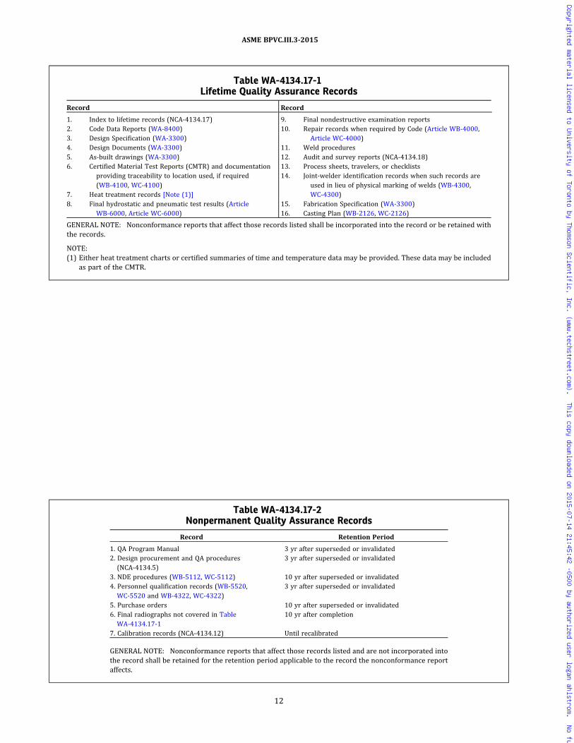
Table WA-4134.17-1Lifetime Quality Assurance Records
Record
1. Index to lifetime records (NCA‐4134.17)2. Code Data Reports (WA-8400)3. Design Specification (WA-3300)4. Design Documents (WA-3300)5. As‐built drawings (WA-3300)6. Certified Material Test Reports (CMTR) and documentation
providing traceability to location used, if required(WB-4100, WC-4100)
7. Heat treatment records [Note (1)]8. Final hydrostatic and pneumatic test results (Article
WB-6000, Article WC-6000)
Record
9. Final nondestructive examination reports10. Repair records when required by Code (Article WB-4000,
Article WC-4000)11. Weld procedures12. Audit and survey reports (NCA‐4134.18)13. Process sheets, travelers, or checklists14. Joint‐welder identification records when such records are
used in lieu of physical marking of welds (WB-4300,WC-4300)
15. Fabrication Specification (WA-3300)16. Casting Plan (WB-2126, WC-2126)
GENERAL NOTE: Nonconformance reports that affect those records listed shall be incorporated into the record or be retained withthe records.
NOTE:(1) Either heat treatment charts or certified summaries of time and temperature data may be provided. These data may be included
as part of the CMTR.
Table WA-4134.17-2Nonpermanent Quality Assurance Records
Record Retention Period
1. QA Program Manual 3 yr after superseded or invalidated2. Design procurement and QA procedures(NCA‐4134.5)
3 yr after superseded or invalidated
3. NDE procedures (WB-5112, WC-5112) 10 yr after superseded or invalidated4. Personnel qualification records (WB-5520,WC-5520 and WB-4322, WC-4322)
3 yr after superseded or invalidated
5. Purchase orders 10 yr after superseded or invalidated6. Final radiographs not covered in TableWA-4134.17-1
10 yr after completion
7. Calibration records (NCA‐4134.12) Until recalibrated
GENERAL NOTE: Nonconformance reports that affect those records listed and are not incorporated intothe record shall be retained for the retention period applicable to the record the nonconformance reportaffects.
12
ASME BPVC.III.3-2015
Copyrighted material licensed to University of Toronto by Thomson Scientific, Inc. (www.techstreet.com). This copy downloaded on 2015-07-14 21:45:42 -0500 by authorized user logan ahlstrom. No further reproduction or distribution is permitted.

ARTICLE WA-5000AUTHORIZED INSPECTION
WA-5100 INTRODUCTION
WA-5110 APPLICABILITY
This Article provides the requirements for inspectionby the Authorized Inspection Agency.
WA-5120 PERFORMANCE OF INSPECTIONWA-5121 Authorized Inspection Agency
(a) The Authorized Inspection Agency shall be accre-dited by the Society in accordance with the provisionsset forth in ASME QAI‐1.
(b) The Authorized Inspection Agency shall notify theSociety when it enters into an agreement with a Certifi-cate Holder, or whenever an existing agreement isterminated.
WA-5122 Authorized Nuclear InspectorSupervisor
The Authorized Inspection Agency shall employAuthorized Nuclear Inspection Supervisors qualified inaccordance with ASME QAI‐1, to supervise the Inspectors.
WA-5123 Authorized Nuclear Inspector
The Authorized Inspection Agency shall also employAuthorized Nuclear Inspectors qualified in accordancewith the latest revision of ASME QAI‐1, to perform inspec-tions required by this Division. The inspections requiredby this Division shall be performed by an Authorized Nu-clear Inspector. Any reference to Inspector throughoutthis Division shall mean Authorized Nuclear Inspector.The Authorized Nuclear Inspector shall not be in the em-ploy of a Certificate Holder.
WA-5125 Duties of Authorized Nuclear InspectorSupervisors
(a) Supervisors, in conjunction with Inspectors em-ployed by the same Authorized Inspection Agency(WA-5121), shall participate in the Society’s review ofthe applicant’s Quality Assurance Program (WA-8160).In those cases where the Supervisor performs the func-tions of the Inspector, he may represent both during thereview of the Program. A Supervisor designated by theAuthorized Inspection Agency shall review and acceptany proposed modifications to Quality Assurance Manualsbefore they are put into effect. The Authorized Nuclear In-spector Supervisor shall audit the Inspector’s perfor-mance at least twice per year at locations where the
Certificate Holder is actively engaged in Section III work.The Supervisor shall be available as needed for consulta-tion and support of the local inspection staff. The Super-visor shall maintain supervisory control over one ormore Authorized Nuclear Inspectors and shall performall of the functions and maintain the records required ofhim in ASME QAI‐1.
(b) The portion of a Certificate Holder’s Quality Assur-ance Program that involves Material Organization activ-ities [NCA‐3820(c)] shall be audited by the Supervisorat least once each year.
WA-5130 ACCESS FOR INSPECTION AGENCYPERSONNEL
WA-5131 Access to the Certificate Holder’sFacilities
(a) The Certificate Holder shall arrange for the Inspec-tion Agency Personnel to have free access at all times tothose locations where Code activities, including thoseconcerned with supply or manufacture of materials, arebeing performed on an item, when so requested. The Cer-tificate Holder shall keep the Inspector informed of theprogress of the work and shall notify him reasonably inadvance when the item will be ready for any requiredtests or inspections.
(b) The Certificate Holder shall provide personnel toaccompany the Authorized Nuclear Inspector Supervisorduring his required audits.
WA-5200 DUTIES OF INSPECTOR
WA-5210 GENERAL INSPECTION DUTIES
(a) The Inspector who performs the detailed inspec-tions in compliance with this Division shall witness orotherwise verify all examinations and make all inspec-tions required by this Division. The Inspector shall alsomake any other inspections and witness or verify (includ-ing making measurements) any other examinations andadditional investigations which, in the Inspector’s judg-ment, are necessary to ascertain whether the item beinginspected has been constructed (WA-1110) in compliancewith the rules of this Division. Parts, including piping sub-assemblies, shall be in accordance with the accepteddocuments (WA-3300).
(b) The duties of the Inspector shall not be interpretedby virtue of these rules to extend to any construction re-quirements beyond those of this Division which may be
13
ASME BPVC.III.3-2015
Copyrighted material licensed to University of Toronto by Thomson Scientific, Inc. (www.techstreet.com). This copy downloaded on 2015-07-14 21:45:42 -0500 by authorized user logan ahlstrom. No further reproduction or distribution is permitted.
set forth in the Fabrication Specifications (WA-3360).However, such requirements shall not result in construc-tion which fails to conform with the requirements of thisDivision.
WA-5220 CATEGORIES OF INSPECTOR’S DUTIES
The duties of the Inspector shall include but not neces-sarily be limited to those given in (a) through (i) below.
(a) verifying the scope of work to be performed[WA-5230(a)];
(b)monitoring of the Certificate Holder’s Quality Assur-ance Program including subcontracted activities(WA-5240);
(c) reviewing of the Certificate Holder’s qualificationrecords (WA-5250);
(d) verifying materials (WA-5260);
(e) witnessing or verifying in‐process fabrication, non-destructive examination, and tests (WA-5270);
(f) witnessing final testing (WA-5280);
(g) reviewing and signing Data Reports (WA-5290);
(h) reviewing drawings and inspecting in accordancewith them;
(i) performing all other duties specifically required inASME QAI‐1.
WA-5230 SCOPE OF WORK, DESIGNSPECIFICATIONS, DESIGN REPORTS,AND FABRICATION SPECIFICATIONS
(a) The Inspector shall verify that the scope stated inthe N‐type Certificate of Authorization includes the workto be performed.
(b) The Inspector shall verify that the Design Specifica-tion, Design Reports, and Fabrication Specifications, whenrequired, are on file and that they have been properly cer-tified in accordance with WA-3351.4, WA-3356, andWA-3361.3.
(c) The Inspector shall not be held responsible for thescope or adequacy of the Design Specifications, for thecompleteness or accuracy of the Design Report or calcula-tions or for the qualification of registered Professional En-gineers certifying documents in compliance with therequirements of this Division.
WA-5240 QUALITY ASSURANCE PROGRAMSWA-5241 Stipulation of Inspections Prior to
Issuance of Process Sheets or Controls
Prior to the issuance of process sheets or controls re-quired by NCA‐4134.9, the Certificate Holder shall reviewthem and the applicable drawings with the Inspector, whoshall then stipulate the inspections he intends to make inorder to fulfill the requirements of WA-5210.
WA-5242 Monitoring of Quality AssurancePrograms
The Inspector shall monitor the performance of theCertificate Holder for conformity to the requirements oftheir Quality Assurance Program accepted by the Society.The Inspector shall verify that all changes to the QualityAssurance Manual have been accepted by the AuthorizedInspection Agency before they are put into effect.
WA-5243 Process Control Checklist
The Inspector shall indicate on the Certificate Holder’sprocess sheets or checklist his concurrence that compli-ance has been attained at each point stipulated by him(WA-5241).
WA-5250 QUALIFICATION RECORDSWA-5251 Review of Qualification Records
The Inspector shall review the qualification records ofthe Certificate Holder.
WA-5253 Welding Procedures
The Inspector shall assure himself that the welding pro-cedures employed in fabrication have been qualified un-der the provisions of this Division. The CertificateHolder shall submit evidence to the Inspector that theserequirements have been met. When there is a specific rea-son to question the welding procedure, the Inspector mayrequire requalification as a requirement for the proce-dure to be used on work subject to his inspection.
WA-5254 Welders and Welding Operators
The Inspector shall assure himself that all welding isperformed by welders or welding operators qualified un-der the provisions of this Division. The Certificate Holdershall make available to the Inspector a certified copy ofthe record of performance qualification tests of eachwelder and welding operator as evidence that these re-quirements have been met. When there is a specific rea-son to question the ability of the welder or the weldingoperator to make welds that meet the requirements ofthe specification, the Inspector may require requalifica-tion before the welder or welding operator is permittedto continue welding on work subject to his inspection.The Inspector shall also assure himself that each welderand welding operator has been assigned an identifyingsymbol and that such symbols are regularly and consis-tently applied when required by this Division.
WA-5255 Examination Procedures
The Inspector shall assure himself that the examinationand testing procedures required by this Division havebeen qualified. When there is a specific reason to questionwhether the examination or testing procedure require-ments are being met, the Inspector may require requalifi-cation of the procedure.
14
ASME BPVC.III.3-2015
Copyrighted material licensed to University of Toronto by Thomson Scientific, Inc. (www.techstreet.com). This copy downloaded on 2015-07-14 21:45:42 -0500 by authorized user logan ahlstrom. No further reproduction or distribution is permitted.
ð15Þ
WA-5256 Nondestructive ExaminationPersonnel
The Inspector has the duty to verify the qualificationand certification of nondestructive examination person-nel employed by the Certificate Holder and has the dutyto monitor the nondestructive examination activitiesand require requalification of any personnel when thereis reason to question the performance of that person. Inaddition, the Inspector shall monitor the CertificateHolder’s Quality Assurance Program as it relates to thenondestructive examination activities of Material Organi-zations, and NDE subcontractors that the CertificateHolder qualified.
WA-5260 MATERIALS, PARTS, AND HEATTREATMENT
WA-5261 Inspection of Materials for ComplianceThe Inspector shall assure himself that all materials
used comply with all applicable requirements of this Divi-sion. The Certificate Holder shall make available to the In-spector certified reports of the results of all testsperformed in accordance with (a) and (b) below:
(a) the material specifications;(b) the requirements in the applicable materials
Articles of this Division, including certified reports ofthe results of all required tests and examinationsperformed.
WA-5262 Dimensional CheckThe Inspector shall satisfy himself:(a) that the item is being constructed within the toler-
ance required by the Design Specification, Design Draw-ings, and Fabrication Specifications, and this Division;
(b) that head and shell sections conform to the pre-scribed shape and meet the thickness requirements;
(c) that fittings and attachments to be welded to thecontainment fit properly to the surface of the contain-ment. If required by the Inspector, the Certificate Holdershall make available accurately formed templates for hisuse.
WA-5263 Check of Heat Treatment PracticeThe Inspector shall satisfy himself that all heat treat-
ment operations required by this Division are correctlyperformed and that the temperature readings and gradi-ents conform to the requirements.
WA-5270 EXAMINATIONS AND TESTSThe Inspector shall witness in‐process fabrication non-
destructive examinations and destructive tests, when fea-sible; alternatively, he shall check the examination andtest records to determine the acceptability of the itemsinvolved.
WA-5280 FINAL TESTS
The Inspector shall witness final tests required by thisDivision and examinations performed during such testsby the Certificate Holder.
WA-5290 DATA REPORTS
The appropriate Data Reports prepared by the Certifi-cate Holder shall be reviewed and signed by the Inspectoronly after they have been certified by a responsible repre-sentative of the Certificate Holder and after he has satis-fied himself that all requirements of this Division havebeen met and that each Data Report certified is a correctrecord.
WA-5300 RESPONSIBILITIES OF THEAUTHORIZED INSPECTIONAGENCY
The responsibilities of the Authorized InspectionAgency shall include but not necessarily be limited tothose given in (a) through (j) below.
(a)Maintain a staff of Authorized Nuclear Inspectorsand Authorized Nuclear Inspector Supervisors(WA-5122 and WA-5123).
(b)Make agreements with Certificate Holders for in-spection service (WA-5121 and WA-8130). Notify the So-ciety whenever such agreements are terminated(WA-5121).
(c) Provide for participation in the Society’s review ofthe applicant’s Quality Assurance Program (WA-5125).
(d) Provide for the review and acceptance of any pro-posed modifications to Quality Assurance Manuals beforethey are put into effect (WA-5125).
(e) Review and accept the Certificate Holder’s methodof securing the nameplate to components to which, be-cause of size or other considerations, the nameplate can-not be directly attached [WA-8220(b)].
(f) Review and accept the Certificate Holder’s alterna-tive method of identification, including the unique meth-od of marking of components to which, because of size orother considerations, nameplates cannot be directly at-tached [WA-8220(b)].
(g) Review and accept the Certificate Holder’s alterna-tive method of marking of parts (WA-8230).
(h) Review and accept the Certificate Holder’s proce-dures for alternative stamping requirements (WA-8311).
(i) Determine by agreement with the Certificate Holderthe sequence for stamping and the completion of the CodeData Report [WA-8310(c)].
(j) And all other duties specifically required in ASMEQAI‐1.
15
ASME BPVC.III.3-2015
Copyrighted material licensed to University of Toronto by Thomson Scientific, Inc. (www.techstreet.com). This copy downloaded on 2015-07-14 21:45:42 -0500 by authorized user logan ahlstrom. No further reproduction or distribution is permitted.
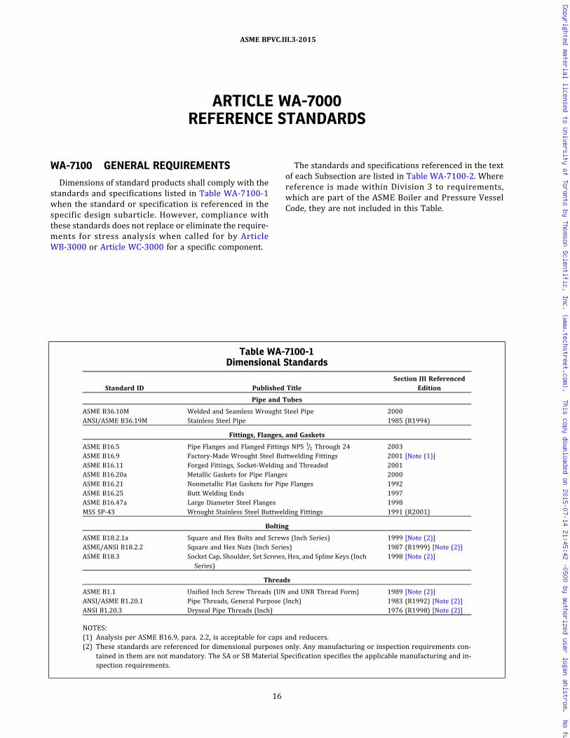
ARTICLE WA-7000REFERENCE STANDARDS
WA-7100 GENERAL REQUIREMENTS
Dimensions of standard products shall comply with thestandards and specifications listed in Table WA-7100-1when the standard or specification is referenced in thespecific design subarticle. However, compliance withthese standards does not replace or eliminate the require-ments for stress analysis when called for by ArticleWB-3000 or Article WC-3000 for a specific component.
The standards and specifications referenced in the textof each Subsection are listed in Table WA-7100-2. Wherereference is made within Division 3 to requirements,which are part of the ASME Boiler and Pressure VesselCode, they are not included in this Table.
Table WA-7100-1Dimensional Standards
Standard ID Published TitleSection III Referenced
Edition
Pipe and Tubes
ASME B36.10M Welded and Seamless Wrought Steel Pipe 2000ANSI/ASME B36.19M Stainless Steel Pipe 1985 (R1994)
Fittings, Flanges, and Gaskets
ASME B16.5 Pipe Flanges and Flanged Fittings NPS 1/2 Through 24 2003ASME B16.9 Factory‐Made Wrought Steel Buttwelding Fittings 2001 [Note (1)]ASME B16.11 Forged Fittings, Socket‐Welding and Threaded 2001ASME B16.20a Metallic Gaskets for Pipe Flanges 2000ASME B16.21 Nonmetallic Flat Gaskets for Pipe Flanges 1992ASME B16.25 Butt Welding Ends 1997ASME B16.47a Large Diameter Steel Flanges 1998MSS SP-43 Wrought Stainless Steel Buttwelding Fittings 1991 (R2001)
Bolting
ASME B18.2.1a Square and Hex Bolts and Screws (Inch Series) 1999 [Note (2)]ASME/ANSI B18.2.2 Square and Hex Nuts (Inch Series) 1987 (R1999) [Note (2)]ASME B18.3 Socket Cap, Shoulder, Set Screws, Hex, and Spline Keys (Inch
Series)1998 [Note (2)]
Threads
ASME B1.1 Unified Inch Screw Threads (UN and UNR Thread Form) 1989 [Note (2)]ANSI/ASME B1.20.1 Pipe Threads, General Purpose (Inch) 1983 (R1992) [Note (2)]ANSI B1.20.3 Dryseal Pipe Threads (Inch) 1976 (R1998) [Note (2)]
NOTES:(1) Analysis per ASME B16.9, para. 2.2, is acceptable for caps and reducers.(2) These standards are referenced for dimensional purposes only. Any manufacturing or inspection requirements con-
tained in them are not mandatory. The SA or SB Material Specification specifies the applicable manufacturing and in-spection requirements.
16
ASME BPVC.III.3-2015
Copyrighted material licensed to University of Toronto by Thomson Scientific, Inc. (www.techstreet.com). This copy downloaded on 2015-07-14 21:45:42 -0500 by authorized user logan ahlstrom. No further reproduction or distribution is permitted.

ð15ÞTable WA-7100-2Standards and Specifications Referenced in Text
Standard ID Published Title
Section IIIReferencedEdition
The American Society of Mechanical Engineers (ASME)
ASME NQA‐1 Quality Assurance Requirements for Nuclear FacilityApplications
2008, 2009a
ASME QAI‐1 Qualifications for Authorized Inspection Latest
American Society for Nondestructive Testing (ASNT)
SNT‐TC‐1A Recommended Practice – Personnel Qualification andCertification in Nondestructive Testing
2011
American Society for Testing and Materials (ASTM)
ASTM E23 Standard Test Methods for Notched Bar Impact Testingof Metallic Materials
2002a
ASTM E186 Standard Reference Radiographs for Heavy‐Walled [2 in.to 41/2 in. (51 mm to 114 mm)] Steel Castings
1967, 1973, 1975
ASTM E208 Standard Test Method for Conducting Drop‐Weight Testto Determine Nil Ductility Transition Temperature ofFerritic Steels
1991
ASTM E280 Standard Reference Radiographs for Heavy‐Walled[41/2 in. to 12 in. (114 mm to 305 mm)] Steel Castings
1968, 1972, 1975
ASTM E399 Standard Test Method for Plane‐Strain FractureToughness of Metallic Materials
1983, 1990
ASTM E446 Standard Reference Radiographs for Steel Castings up to2 in. (51 mm) in Thickness
1972, 1975, 1978
ASTM E604 Standard Test Method for Dynamic Tear Testing ofMetallic Materials
1983
ASTM E1820 Standard Test Method for Measurement of FractureToughness
2001
American Welding Society (AWS)
AWS A4.2 Calibrating Magnetic Instruments to Measure the DeltaFerrite Content of Austenitic and DuplexFerritic‐Austenitic Stainless Steel
1991
American National Standards Institute (ANSI)
ANSI N14.5 Leakage Test on Packages for Transportation 1997
17
ASME BPVC.III.3-2015
Copyrighted material licensed to University of Toronto by Thomson Scientific, Inc. (www.techstreet.com). This copy downloaded on 2015-07-14 21:45:42 -0500 by authorized user logan ahlstrom. No further reproduction or distribution is permitted.
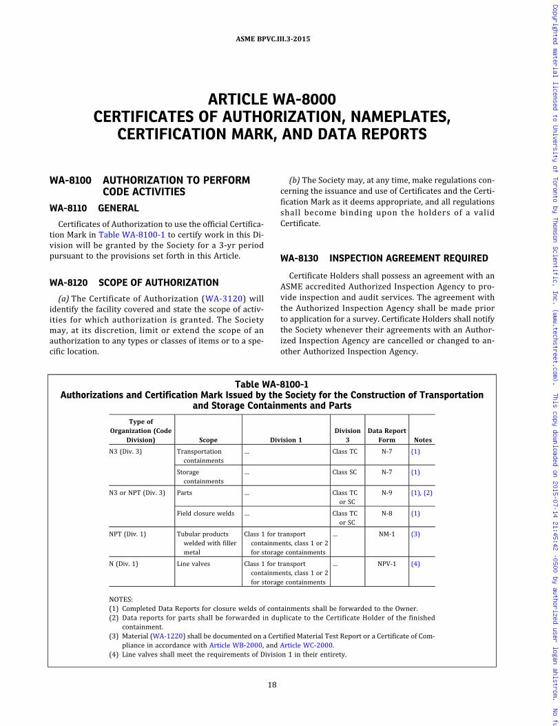
ARTICLE WA-8000CERTIFICATES OF AUTHORIZATION, NAMEPLATES,
CERTIFICATION MARK, AND DATA REPORTS
WA-8100 AUTHORIZATION TO PERFORMCODE ACTIVITIES
WA-8110 GENERAL
Certificates of Authorization to use the official Certifica-tion Mark in Table WA-8100-1 to certify work in this Di-vision will be granted by the Society for a 3-yr periodpursuant to the provisions set forth in this Article.
WA-8120 SCOPE OF AUTHORIZATION
(a) The Certificate of Authorization (WA-3120) willidentify the facility covered and state the scope of activ-ities for which authorization is granted. The Societymay, at its discretion, limit or extend the scope of anauthorization to any types or classes of items or to a spe-cific location.
(b) The Society may, at any time, make regulations con-cerning the issuance and use of Certificates and the Certi-fication Mark as it deems appropriate, and all regulationsshall become binding upon the holders of a validCertificate.
WA-8130 INSPECTION AGREEMENT REQUIRED
Certificate Holders shall possess an agreement with anASME accredited Authorized Inspection Agency to pro-vide inspection and audit services. The agreement withthe Authorized Inspection Agency shall be made priorto application for a survey. Certificate Holders shall notifythe Society whenever their agreements with an Author-ized Inspection Agency are cancelled or changed to an-other Authorized Inspection Agency.
Table WA-8100-1Authorizations and Certification Mark Issued by the Society for the Construction of Transportation
and Storage Containments and Parts
Type ofOrganization (Code
Division) Scope Division 1Division
3Data Report
Form Notes
N3 (Div. 3) Transportationcontainments
… Class TC N‐7 (1)
Storagecontainments
… Class SC N‐7 (1)
N3 or NPT (Div. 3) Parts … Class TCor SC
N‐9 (1), (2)
Field closure welds … Class TCor SC
N‐8 (1)
NPT (Div. 1) Tubular productswelded with fillermetal
Class 1 for transportcontainments, class 1 or 2for storage containments
… NM‐1 (3)
N (Div. 1) Line valves Class 1 for transportcontainments, class 1 or 2for storage containments
… NPV‐1 (4)
NOTES:(1) Completed Data Reports for closure welds of containments shall be forwarded to the Owner.(2) Data reports for parts shall be forwarded in duplicate to the Certificate Holder of the finished
containment.(3) Material (WA-1220) shall be documented on a Certified Material Test Report or a Certificate of Com-
pliance in accordance with Article WB-2000, and Article WC-2000.(4) Line valves shall meet the requirements of Division 1 in their entirety.
18
ASME BPVC.III.3-2015
Copyrighted material licensed to University of Toronto by Thomson Scientific, Inc. (www.techstreet.com). This copy downloaded on 2015-07-14 21:45:42 -0500 by authorized user logan ahlstrom. No further reproduction or distribution is permitted.

WA-8140 QUALITY ASSURANCE PROGRAMREQUIREMENTS
It is a requirement that a Certificate Holder have aQuality Assurance Program (Article WA-4000) that hasbeen evaluated and accepted by the Society.
WA-8150 APPLICATION FOR AUTHORIZATION
An Organization desiring a Certificate of Authorizationshall apply to the Society upon forms issued by the So-ciety describing the scope of Code activities to beperformed.
WA-8151 Field Operations
The N3 or NPT Certificate of Authorization may be ex-tended to include field operations such as the completionor repair of containments and parts constructed underthat authorization. Except as permitted in WA-8152, theSociety requires a survey of each field site to assure thatthe Quality Assurance Program described in the Manual isimplemented and enforced.
WA-8152 Field Operations for ContainmentClosure Welds
The N3 or NPT Certificates may be extended to field lo-cations for making final closure welds to loaded spent nu-clear fuel or high level radioactive materials and wastecontainments without a site survey by the Society,provided.
(a) the control of materials, special processes, examina-tions, inspections, tests, and certification at field locationsshall be described in the Certificate Holders Quality As-surance Manual, including involvement of the Inspector;
(b) the Certificate Holders Quality Assurance Programhas been reviewed and accepted by the Authorized In-spection Agency to confirm (a) above prior to any weldingat field locations;
(c) unique identifiers are permanently marked on eachof the containment parts that are to be assembledtogether;
(d) the welds are to be made in accordance with the re-quirements of the Fabrication Specification; and
(e) the Data Report for each containment includes theunique identifiers of (c) above.
WA-8153 Shop Assembly
Shop assembly of containments, or containments topiping or other items, may be by N‐type CertificateHolders if such activities are included within the scopeof their N‐type Certificate of Authorization.
WA-8154 Code Activities Prior to Certification
Code activities performed prior to issuance of a N3 orNPT Certificate of Authorization shall be subject to the ac-ceptance of the Inspector.
WA-8160 EVALUATION FOR AUTHORIZATIONWA-8161 Evaluation for Certificate of
Authorization
(a) Applicants for a new or renewed N3 or NPT Certifi-cate of Authorization for construction require a survey oftheir facilities. The purpose of the survey is to evaluatethe applicant’s Quality Assurance Manual and the imple-mentation of the Quality Assurance Program.
(b) The extent of the survey will be determined by theSociety based on a review of the applicant’s intendedscope of Code activities described in the application.The acceptance by the Society of the Quality AssuranceProgram shall not be interpreted to mean endorsementof technical capability to perform design work such assystem design or stress analysis. Such capability is im-plied for the specific containment involved by the certifi-cation of Design Reports (WA-3356) by a RegisteredProfessional Engineer.
(c) Authorization to certify a Data Report or apply aCertification Mark to an item will be granted only aftera survey by the Society has satisfactorily demonstratedthe adequacy and implementation of the Quality Assur-ance Program.
WA-8170 ISSUANCE OF AUTHORIZATION
Each Certificate Holder shall have agreed that each Cer-tificate and Certification Mark (if one is issued) is at alltimes the property of the Society, that it will be used ac-cording to the rules and regulations of this Division, andthat the Certificate and Certification Mark will bepromptly returned to the Society upon demand, or whenthe Certificate Holder discontinues the scope of Code ac-tivities covered by his Certificate. The holder of a Certifi-cation Mark shall not permit any other party to use itsCertificate or Certification Mark. The Society reservesthe absolute right to cancel or refuse to renew suchauthorization, returning fees paid for the prorated unex-pired term.
WA-8180 RENEWAL OF AUTHORIZATION
Not later than 6 months prior to the date of expirationof any Certificate, the Certificate Holder shall apply for arenewal of such authorization and the issuance of a newCertificate.
WA-8200 NAMEPLATES AND STAMPINGWITH CERTIFICATION MARK
WA-8210 GENERAL REQUIREMENTSWA-8211 Nameplates
(a) Each containment or part to which a CertificationMark is applied shall have a nameplate, except as other-wise permitted by this subarticle. Marking shall be as re-quired by (1) through (5) below.
19
ASME BPVC.III.3-2015
Copyrighted material licensed to University of Toronto by Thomson Scientific, Inc. (www.techstreet.com). This copy downloaded on 2015-07-14 21:45:42 -0500 by authorized user logan ahlstrom. No further reproduction or distribution is permitted.
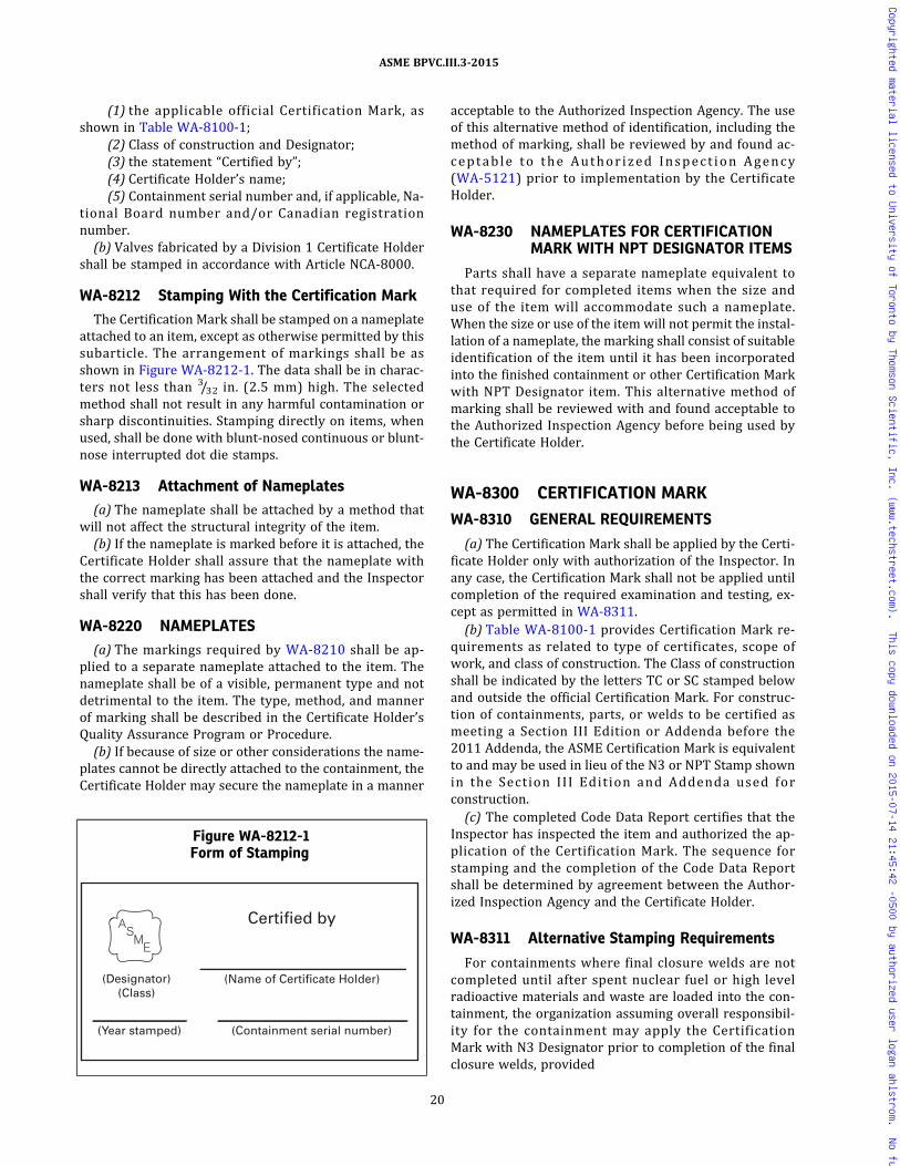
(1) the applicable official Certification Mark, asshown in Table WA-8100-1;
(2) Class of construction and Designator;(3) the statement “Certified by”;(4) Certificate Holder’s name;(5) Containment serial number and, if applicable, Na-
tional Board number and/or Canadian registrationnumber.(b) Valves fabricated by a Division 1 Certificate Holder
shall be stamped in accordance with Article NCA‐8000.
WA-8212 Stamping With the Certification Mark
The Certification Mark shall be stamped on a nameplateattached to an item, except as otherwise permitted by thissubarticle. The arrangement of markings shall be asshown in Figure WA-8212-1. The data shall be in charac-ters not less than 3/32 in. (2.5 mm) high. The selectedmethod shall not result in any harmful contamination orsharp discontinuities. Stamping directly on items, whenused, shall be done with blunt‐nosed continuous or blunt‐nose interrupted dot die stamps.
WA-8213 Attachment of Nameplates
(a) The nameplate shall be attached by a method thatwill not affect the structural integrity of the item.(b) If the nameplate is marked before it is attached, the
Certificate Holder shall assure that the nameplate withthe correct marking has been attached and the Inspectorshall verify that this has been done.
WA-8220 NAMEPLATES
(a) The markings required by WA-8210 shall be ap-plied to a separate nameplate attached to the item. Thenameplate shall be of a visible, permanent type and notdetrimental to the item. The type, method, and mannerof marking shall be described in the Certificate Holder’sQuality Assurance Program or Procedure.(b) If because of size or other considerations the name-
plates cannot be directly attached to the containment, theCertificate Holder may secure the nameplate in a manner
acceptable to the Authorized Inspection Agency. The useof this alternative method of identification, including themethod of marking, shall be reviewed by and found ac-ceptable to the Author ized Inspect ion Agency(WA-5121) prior to implementation by the CertificateHolder.
WA-8230 NAMEPLATES FOR CERTIFICATIONMARK WITH NPT DESIGNATOR ITEMS
Parts shall have a separate nameplate equivalent tothat required for completed items when the size anduse of the item will accommodate such a nameplate.When the size or use of the itemwill not permit the instal-lation of a nameplate, the marking shall consist of suitableidentification of the item until it has been incorporatedinto the finished containment or other Certification Markwith NPT Designator item. This alternative method ofmarking shall be reviewed with and found acceptable tothe Authorized Inspection Agency before being used bythe Certificate Holder.
WA-8300 CERTIFICATION MARK
WA-8310 GENERAL REQUIREMENTS
(a) The Certification Mark shall be applied by the Certi-ficate Holder only with authorization of the Inspector. Inany case, the Certification Mark shall not be applied untilcompletion of the required examination and testing, ex-cept as permitted in WA-8311.(b) Table WA-8100-1 provides Certification Mark re-
quirements as related to type of certificates, scope ofwork, and class of construction. The Class of constructionshall be indicated by the letters TC or SC stamped belowand outside the official Certification Mark. For construc-tion of containments, parts, or welds to be certified asmeeting a Section III Edition or Addenda before the2011 Addenda, the ASME Certification Mark is equivalentto and may be used in lieu of the N3 or NPT Stamp shownin the Section III Edition and Addenda used forconstruction.(c) The completed Code Data Report certifies that the
Inspector has inspected the item and authorized the ap-plication of the Certification Mark. The sequence forstamping and the completion of the Code Data Reportshall be determined by agreement between the Author-ized Inspection Agency and the Certificate Holder.
WA-8311 Alternative Stamping Requirements
For containments where final closure welds are notcompleted until after spent nuclear fuel or high levelradioactive materials and waste are loaded into the con-tainment, the organization assuming overall responsibil-ity for the containment may apply the CertificationMark with N3 Designator prior to completion of the finalclosure welds, provided
Figure WA-8212-1Form of Stamping
Certified by
(Name of Certificate Holder)
(Containment serial number) (Year stamped)
(Designator)(Class)
20
ASME BPVC.III.3-2015
Copyrighted material licensed to University of Toronto by Thomson Scientific, Inc. (www.techstreet.com). This copy downloaded on 2015-07-14 21:45:42 -0500 by authorized user logan ahlstrom. No further reproduction or distribution is permitted.
(a) unique identifiers are permanently marked on eachof the containment parts that are to be assembledtogether;
(b) the Data Report for each containment includes theassigned unique identifiers; and
(c) the procedure for controlling, and the use of, the un-ique identifiers shall be included in the Certificate HoldersQuality Assurance Program and accepted by the Certifi-cate Holders Authorized Inspection Agency prior to use.
WA-8330 REMOVABLE ITEMS
Removable items that form part of a containment shallhave unique markings identifiable to an individualcontainment.
WA-8400 DATA REPORTS
WA-8410 GENERAL REQUIREMENTS
The appropriate Data Report,7 as specified in TableWA-8100-1, shall be filled out by the Certificate Holderand shall be signed by the Certificate Holder and the In-spector for each item (except as provided elsewhere inthis Article) to be marked with a Certification Mark. Anyquantity to which units apply shall be entered on theManufacturer’s Data Report with the chosen units.
WA-8412 Availability of Data Reports
All Data Reports and referenced supporting materialshall be available to the Inspector, Owner, and enforce-ment, or regulatory authority having jurisdiction.
21
ASME BPVC.III.3-2015
Copyrighted material licensed to University of Toronto by Thomson Scientific, Inc. (www.techstreet.com). This copy downloaded on 2015-07-14 21:45:42 -0500 by authorized user logan ahlstrom. No further reproduction or distribution is permitted.

FORM N-7 NUCLEAR CONTAINMENTS
As Required by the Provisions of the ASME Code, Section III, Division 3
(07/10)
1. Manufactured and certified by
2. Manufactured for
3. Transport and/or Storage
4. Type
5. ASME Code, Section III, Division 3
6. Shell
7. Seams Long
If removable, bolts used; . If quick opening closure or other fastening, describe in detail
; girth
8. Heads
9. Design pressure
10. Supports
11. Nozzles
12. Parts supplied by others (Data Reports attached).
13. For containments list identifying markings of matching items to be joined in the field by welding.
14. Remarks
to be welded to
(a) Part (b) Serial No. (c) CRN No. (d) National Bd. No.
Purpose QuantityDiameteror Size Type Material Thickness Location
ReinforcementMaterial
HowAttached
Lugs Legs Other Attached
He leak test
at . Min. pressure-test temp. . Pneu., hydro., or comb. test pressure
(a)
(c)
(d)
(b)
CrownRadiusThickness
Location (top,bottom, ends)
KnuckleRadius
EllipticalRatio
ConicalApex Angle
HemisphericalRadius
FlatDiameter
Side to Pressure(convex or concave)
(CRN) (National Bd. no.) (year built)(Certificate Holder’s serial no.)(Containment serial no.)(horizontal or vertical)
(edition) [addenda (if applicable) date]
(nominal thickness)
(describe)
(shell assembly)(closure plates, heads)
[maximim acc. leak rate (from fab. spec.)]
(quantity)(quantity)(yes or no) (where and how)
(type) (HT) (RT or UT) (joint eff. %)(joint eff. %)
(tensile strength) (tensile strength)
(tensile strength) (tensile strength)
(tensile strength)(material spec. no.) [length (overall)](diameter ID)
(class) (Code Case no.)
(name and address)
(RT or UT)(HT)(type)
[(a) material spec. no.] [(b) material spec. no.]
[(c) material spec. no.] [(d) material spec. no.]
Pg. 1 of
22
ASME BPVC.III.3-2015
Copyrighted material licensed to University of Toronto by Thomson Scientific, Inc. (www.techstreet.com). This copy downloaded on 2015-07-14 21:45:42 -0500 by authorized user logan ahlstrom. No further reproduction or distribution is permitted.

FORM N-7 (Back — Pg. 2 of )
Certificate Holder’s Serial No.
CERTIFICATE OF COMPLIANCE FOR OVERALL RESPONSIBILITY
CERTIFICATION OF DESIGN
Design Specification on file at
Fabrication Specification on file at
Fabrication Specification certified by P.E. State or Prov.
Design Report certified by P.E. State or Prov.
Design Report on file at
Design Specification certified by P.E. State or Prov.
Reg. No.
Reg. No.
Reg. No.
Following completion of the above, the Certificate of Authorization Holder accepting overall responsibility for this Division 3 containment shall complete the following statement:We certify that the statements made by this report are correct and that construction of the items described in this Data Report conforms to the rules of the construction of the ASME Code, Section III, Division 3.
N3 Certificate of Authorization No. Expires
Date N3 Certificate Holder Signed(authorized representative)
CERTIFICATE OF INSPECTION
I, the undersigned, holding a valid commission issued by the National Board of Boiler and Pressure Vessel Inspectors and employed by
of
Date Signed Commission(Authorized Nuclear Inspector) [National Board Number and Endorsement]
CERTIFICATE OF SHOP COMPLIANCE
We certify that the statements made in this report are correct and that this nuclear containment conforms to the rules for construction of the ASME Code, Section III, Division 3.
N3 Certificate of Authorization No. ExpiresDate Name Signed
(N3 Certificate Holder) (authorized representative)
CERTIFICATE OF SHOP INSPECTION
I, the undersigned, holding a valid commission issued by the National Board of Boiler and Pressure Vessel Inspectors and employed by
of have inspected the component described in this Data Report on
Date Signed Commission(Authorized Nuclear Inspector) [National Board Number and Endorsement]
(07/11)
have compared the statements described on this Data Report with those described in the attached Certificate Hold- er's Data Reports and to the best of my knowledge and belief, the described items have been constructed in accordance with the ASME Code, Section III, Division 3.By signing this certificate neither the inspector nor his employer makes any warranty, expressed or implied, concerning the items described in this Data Report. Furthermore, neither the inspector nor his employer shall be liable in any manner for any personal injury or property damage or a loss of any kind arising from or connected with this inspection.
, and state that to the best of my knowledge and belief, the Certificate Holder has constructed this component in accordance with the ASME Code, Section III, Division 3.By signing this certificate neither the inspector nor his employer makes any warranty, expressed or implied, concerning the component described in this Data Report. Furthermore, neither the inspector nor his employer shall be liable in any manner for any personal injury or property damage or a loss of any kind arising from or connected with this inspection.
23
ASME BPVC.III.3-2015
Copyrighted material licensed to University of Toronto by Thomson Scientific, Inc. (www.techstreet.com). This copy downloaded on 2015-07-14 21:45:42 -0500 by authorized user logan ahlstrom. No further reproduction or distribution is permitted.
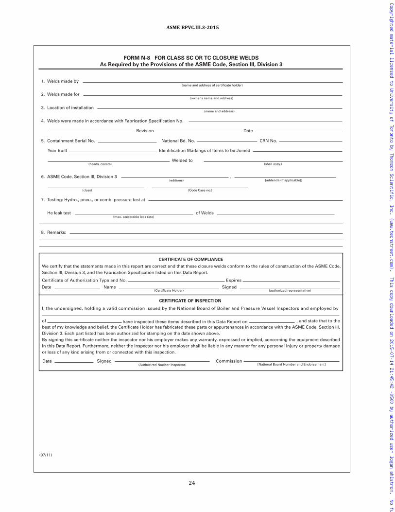
1. Welds made by
2. Welds made for
3. Location of installation
4. Welds were made in accordance with Fabrication Specification No.
5. Containment Serial No.
6. ASME Code, Section III, Division 3 ,
7. Testing: Hydro., pneu., or comb. pressure test at
8. Remarks:
He leak test of Welds
Year Built Identification Markings of Items to be Joined
Welded to
Revision
National Bd. No. CRN No.
Date
(name and address of certificate holder)
(owner’s name and address)
(heads, covers)
(editions)
(class) (Code Case no.)
(max. acceptable leak rate)
[addenda (if applicable)]
(shell assy.)
(name and address)
FORM N-8 FOR CLASS SC OR TC CLOSURE WELDS
As Required by the Provisions of the ASME Code, Section III, Division 3
CERTIFICATE OF COMPLIANCE
We certify that the statements made in this report are correct and that these closure welds conform to the rules of construction of the ASME Code, Section III, Division 3, and the Fabrication Specification listed on this Data Report.
Certificate of Authorization Type and No. Expires
Date Name Signed(Certificate Holder) (authorized representative)
CERTIFICATE OF INSPECTION
I, the undersigned, holding a valid commission issued by the National Board of Boiler and Pressure Vessel Inspectors and employed by
of have inspected these items described in this Data Report on
Date Signed Commission(Authorized Nuclear Inspector) [National Board Number and Endorsement]
(07/11)
, and state that to the best of my knowledge and belief, the Certificate Holder has fabricated these parts or appurtenances in accordance with the ASME Code, Section III, Division 3. Each part listed has been authorized for stamping on the date shown above.By signing this certificate neither the inspector nor his employer makes any warranty, expressed or implied, concerning the equipment described in this Data Report. Furthermore, neither the inspector nor his employer shall be liable in any manner for any personal injury or property damage or loss of any kind arising from or connected with this inspection.
24
ASME BPVC.III.3-2015
Copyrighted material licensed to University of Toronto by Thomson Scientific, Inc. (www.techstreet.com). This copy downloaded on 2015-07-14 21:45:42 -0500 by authorized user logan ahlstrom. No further reproduction or distribution is permitted.
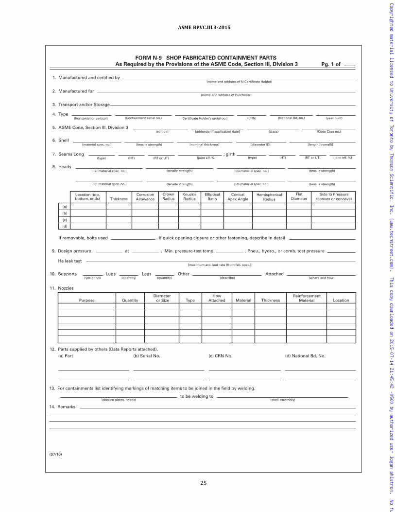
FORM N-9 SHOP FABRICATED CONTAINMENT PARTS
As Required by the Provisions of the ASME Code, Section III, Division 3 Pg. 1 of
(07/10)
1. Manufactured and certified by
2. Manufactured for
3. Transport and/or Storage
4. Type
5. ASME Code, Section III, Division 3
6. Shell
7. Seams Long
If removable, bolts used . If quick opening closure or other fastening, describe in detail
; girth
8. Heads
9. Design pressure
10. Supports
11. Nozzles
12. Parts supplied by others (Data Reports attached).
13. For containments list identifying markings of matching items to be joined in the field by welding.
14. Remarks
to be welding to
(a) Part (b) Serial No. (c) CRN No. (d) National Bd. No.
Purpose QuantityDiameter or Size Type Material Thickness Location
ReinforcementMaterial
HowAttached
Lugs Legs Other Attached
He leak test
at . Min. pressure-test temp. . Pneu., hydro., or comb. test pressure
(a)
(c)
(d)
(b)
CrownRadiusThickness
CorrosionAllowance
Location (top,bottom, ends)
KnuckleRadius
EllipticalRatio
ConicalApex Angle
HemisphericalRadius
FlatDiameter
Side to Pressure(convex or concave)
(CRN) (National Bd. no.) (year built)(Certificate Holder’s serial no.)(Containment serial no.)(horizontal or vertical)
(edition) [addenda (if applicable) date]
(nominal thickness)
(describe)
(shell assembly)(closure plates, heads)
[maximum acc. leak rate (from fab. spec.)]
(quantity)(quantity)(yes or no) (where and how)
(type) (HT) (RT or UT) (joint eff. %)(joint eff. %)
(tensile strength) (tensile strength)
(tensile strength) (tensile strength)
(tensile strength)(material spec. no.) [length (overall)](diameter ID)
(class) (Code Case no.)
(name and address of Purchaser)
(name and address of N Certificate Holder)
(RT or UT)(HT)(type)
[(a) material spec. no.] [(b) material spec. no.]
[(c) material spec. no.] [(d) material spec. no.]
25
ASME BPVC.III.3-2015
Copyrighted material licensed to University of Toronto by Thomson Scientific, Inc. (www.techstreet.com). This copy downloaded on 2015-07-14 21:45:42 -0500 by authorized user logan ahlstrom. No further reproduction or distribution is permitted.

FORM N-9 (Back — Pg. 2 of )
Certificate Holder’s Serial No.
15. Fabrication specification used for the manufacture of this itemrevision no. prepared byCertified by P.E. State or Prov. Reg. No.
CERTIFICATE OF SHOP COMPLIANCE
We certify that the statements made by this report are correct and that this (these)
conforms to the rules of the construction of the ASME Code, Section III, Division 3Certificate of Authorization Type and No. Expires
Date Name Signed(NPT Certificate Holder) (authorized representative)
CERTIFICATE OF SHOP INSPECTION
I, the undersigned, holding a valid commission issued by the National Board of Boiler and Pressure Vessel Inspectors and employed by
of have inspected these items described in this Data Report on
Date Signed Commission[National Board Number and Endorsement](Authorized Nuclear Inspector)
, and state that to the best of my knowledge and belief, the Certificate Holder has fabricated these parts or appurtenances in accordance with the ASME Code, Section III, Division 3. Each part listed has been authorized for stamping on the date shown above.By signing this certificate, neither the inspector nor his employer makes any warranty, expressed or implied, concerning the equipment described in this Data Report. Furthermore, neither the inspector nor his employer shall be liable in any manner for any personal injury or property damage or a loss of any kind arising from or connected with this inspection.
(07/11)
26
ASME BPVC.III.3-2015
Copyrighted material licensed to University of Toronto by Thomson Scientific, Inc. (www.techstreet.com). This copy downloaded on 2015-07-14 21:45:42 -0500 by authorized user logan ahlstrom. No further reproduction or distribution is permitted.
ARTICLE WA-9000GLOSSARY
WA-9100 INTRODUCTION
This Article defines selected terms used in this Division.The definitions in this Glossary shall prevail should a con-flict exist with definitions found elsewhere in this Divisionor other documents referenced in this Division. Unless de-fined below, the definitions of Article NCA‐9000 shallapply.
WA-9200 DEFINITIONS
Authorized Nuclear Inspector: an Authorized Nuclear In-spector is an employee of an Authorized InspectionAgency who has qualifications for and has been properlyqualified for Division 3.
Authorized Nuclear Inspector Supervisor: an AuthorizedNuclear Inspector Supervisor is an employee of anAuthorized Inspection Agency who has been assignedby that agency to oversee and direct the work of one ormore Authorized Nuclear Inspectors and who has qualifi-cations for and has been properly qualified for Division 3.
Certification Mark: a metallic stamp issued by the Societyfor use in impressing one of the symbols shown in TableWA-8100-1.
Class SC: the Division 3 classification assigned to storagecontainments.
Class TC: the Division 3 classification assigned to trans-portation containments.
Code Class: the classification, specified in the Design Spec-ification, which establishes the rules for design and con-struction of items.
component: a containment, valve or appurtenance, that isdesigned, constructed, and stamped in accordance withthe rules of this Division.
construction (as used in Division 3): an all‐inclusive termcomprising materials, design, fabrication, examination,testing, inspection, and certification required in the man-ufacture of an item.
containment: an enclosure that serves as a barrier forspent nuclear fuels or high level radioactive material orwaste within a prescribed volume for transportation orstorage.
containment closure weld: a weld made to close the con-tainment after spent nuclear fuel or high level radioactivemater ia ls or waste have been loaded into thecontainment.
Design Documents: documents used to establish the de-sign requirements, which include those criteria, para-meters, bases, or other design requirements upon whichdetailed final design is based. For this Division, these in-clude the Design Specifications and any other documentsreferenced by them. Additionally, Design Documents arethe output of the above and provide the technical descrip-tion of the item; these include Certified Design Reports,drawings, calculations, and Fabrication Specifications.
Design Specification (Division 3): a document prepared bythe N3 Certificate Holder which provides a complete basisfor design in accordance with this Division.
disposal: the permanent placement of spent nuclear fuelor high-level radioactive material and waste in arepository.
energy-limited dynamic event: a time-dependent, nonre-peating event characterized by an impact or otherimpulsive-type mechanical loading with a known levelof energy content.
examination: specific actions by qualified personnel usingqualified procedures to verify that items and fabricationprocesses are in conformance with specified require-ments. This term, when used in conjunction with qualifi-cation of personnel to perform quality‐related activities,shall mean a written examination.
Fabrication Specification: a document, or set of docu-ments, prepared by the N3 Certificate Holder that estab-lishes the requirements for fabrication.
Inspector: the Authorized Nuclear Inspector as defined inWA-5123.
internal support structures: items used within transporta-tion or storage containments that perform a combinationof structural and configuration control and other func-tions as described by the Design Specification (e.g., heattransfer and criticality).
item: a product constructed under a Certificate of Author-ization (WA-3120) or material (WA-1220).
27
ASME BPVC.III.3-2015
Copyrighted material licensed to University of Toronto by Thomson Scientific, Inc. (www.techstreet.com). This copy downloaded on 2015-07-14 21:45:42 -0500 by authorized user logan ahlstrom. No further reproduction or distribution is permitted.

material: for Section III, Division 3, metallic materialsmanufactured to an SA, SB, SFA, or any other materialspecification permitted by this Division.
modification: a change to an item made necessary by, orresulting in, a change in design requirements.
N3 Certificate Holder (Division 3): the organization thatcauses a Design Specification, Design Report, and Fabrica-tion Specification to be developed. This organization as-sumes responsibility for Code compliance with respectto materials, design, fabrication, examination, testing, in-spection, certification, and stamping of items constructedto the requirements of this Division.
Owner: the organization that takes legal ownership of aDivision 3 component.
qualified source material: metallic products produced byan approved supplier, Material Organization, or Certifi-cate Holder in accordance with the requirements ofWA-3800, or the output of the qualification process re-quirements of NCA-3855.5.
quality control: measurement of the characteristics of anitem or process to determine conformance to specifiedrequirements.
Quality System Certificate: a Certificate issued by the So-ciety that permits an organization to perform specifiedMaterial Organization activities in accordance with Coderequirements.
regulatory authority: a Federal Government Agency, suchas the United States Nuclear Regulatory Commission, em-powered to issue and enforce regulations concerning thedesign and construction of containments for transporta-tion and storage of spent nuclear fuel and high level radio-active material and waste.
shop drawings: drawings which describe fabrication de-tails, physical dimensions, arrangements, and any signifi-cant engineer ing features needed to estab l ishconformance to the Fabrication Specification, and thisDivision.
source material: metallic products used by a Material Or-ganization or Certificate Holder in a product form conver-s i on proces s in the manu fac tu re o f ma te r i a l
[NCA-3851.2(a)(1)], or in a qualification process basedon test and examination to the requirements of the mate-rial specification [NCA-3855.5(a)(2) and (3)]. Source ma-terial may be qualified or unqualified.
special process: a process, the results of which are highlydependent on the control of the process or skill of the op-erator, or both.
storage: the interim placement of spent fuel or high-levelradioactive material and waste in a Section III, Division 3,Class SC containment in accordance with specifiedrequirements.
supplier: any individual or organization that furnishes ma-terials or services in accordance with a procurementdocument.
survey: a documented evaluation of an organization’s abil-ity to perform Code activities as verified by a determina-tion of the adequacy of the organization’s quality programand by a review of the implementation of that program atthe location of the work.
testing: an element of verification for the determination ofthe capability of an item to meet specified requirementsby subjecting the item to a set of physical, chemical, envir-onmental, or operating conditions.
traceability: the ability to verify the history, location, orapp l i ca t ion o f an i t em by means o f recordedidentification.
transportation: the conveyance of spent nuclear fuel orhigh-level radioactive material and waste over public ac-cess routes in a Section III, Division 3, Class TC contain-ment in accordance with specified requirements.
unqualified source material: source material not producedby a Certificate Holder, Material Organization, or ap-proved supplier in accordance with the requirements ofWA-3800.
use‐as‐is: only applicable requirements of this Divisionhave been met.
verification: a review to ensure that activities have beenperformed and documented in accordance with applic-able requirements.
28
ASME BPVC.III.3-2015
Copyrighted material licensed to University of Toronto by Thomson Scientific, Inc. (www.techstreet.com). This copy downloaded on 2015-07-14 21:45:42 -0500 by authorized user logan ahlstrom. No further reproduction or distribution is permitted.
SUBSECTION WBCLASS TC TRANSPORTATION
CONTAINMENTS
ARTICLE WB-1000INTRODUCTION
WB-1100 SCOPE
(a) Subsection WB contains rules for the material, de-sign, fabrication, examination, testing, marking, stamping,and preparation of reports by the Certificate Holder forClass TC transportation containments for spent nuclearfuel and high level radioactive waste and materials.
(b) The rules of Subsection WB cover the strength andcontainment integrity of items the failure of which wouldviolate the containment boundary. The rules cover loadstresses but do not cover deterioration which may occurin service as a result of corrosion, radiation effects, or in-stability of containment materials. WA-1130 further lim-its the rules of this Subsection.
WB-1120 RULES FOR CLASS TCTRANSPORTATION CONTAINMENTS
(a) Class TC transportation containments shall be con-structed in accordance with the rules of this Subsection.
(b) Valves, classified as part of the containment by theDesign Specification, shall be classified as Class 1 andshall meet the requirements of Division 1 in lieu of allother requirements of this Division.
(c) Subsection WB does not contain rules to cover alldetails of construction of Class TC containments. Wherecomplete details are not provided in this Subsection, itis intended that the N3 Certificate Holder, subject to re-view by the Inspector, shall provide the details of con-struction which will be consistent with those providedby the rules of this Subsection.
WB-1130 BOUNDARIES OF JURISDICTIONWB-1131 Boundary of Containments
The Design Specification shall define the boundary of acontainment. The containment includes the vessel andany penetrations attached to the vessel.
WB-1132 Boundary Between a Containment andAttachments
WB-1132.1 Attachments.(a) An attachment is an element in contact with or con-
nected to the inside or outside of a containment, whichmay perform a containment function, and either a struc-tural or nonstructural function.
(b) Attachments that do not perform a containmentfunction include items such as stiffeners or containmentopening reinforcement.
(c) Attachments with a noncontainment function in-clude items in the containment support load path suchas support and shear lugs, brackets, trunnions and skirts.
(d) Attachments with a structural function (structuralattachments) perform a containment function or are inthe containment support load path.
(e) Attachments with a nonstructural function (non-structural attachments) do not perform a containmentfunction nor are they in the containment support loadpath. Nonstructural attachments include items such asnameplates and lifting lugs.
WB-1132.2 Jurisdictional Boundary. The jurisdic-tional boundary between a containment and an attach-ment defined in the Design Specification shall not beany closer to the containment than as defined in (a)through (g) below.
(a) Attachments forged with the containment or weldbuildup on the containment surface shall be consideredpart of the containment.
(b) Attachments, welds, and fasteners having a contain-ment funct ion shal l be cons idered part of thecontainment.
(c) Except as provided in (d) and (e) below, the bound-ary between a containment and an attachment not havinga containment function shall be at the surface of thecontainment.
29
ASME BPVC.III.3-2015
Copyrighted material licensed to University of Toronto by Thomson Scientific, Inc. (www.techstreet.com). This copy downloaded on 2015-07-14 21:45:42 -0500 by authorized user logan ahlstrom. No further reproduction or distribution is permitted.

(d) The first connecting weld of a structural attachmentthat does not perform a containment function to a con-tainment shall be considered part of the containment.(e) The first connecting weld of a welded nonstructural
attachment to a containment shall be considered part ofthe attachment.
(f) Mechanical fasteners used to connect an attachmentthat does not perform a containment function to the con-tainment shall be considered part of the attachment.(g) The boundary may be located further from the con-
tainment portion of the containment than as defined in(a) through (f) above when specified in the DesignSpecification.
30
ASME BPVC.III.3-2015
Copyrighted material licensed to University of Toronto by Thomson Scientific, Inc. (www.techstreet.com). This copy downloaded on 2015-07-14 21:45:42 -0500 by authorized user logan ahlstrom. No further reproduction or distribution is permitted.
ARTICLE WB-2000MATERIAL
WB-2100 GENERAL REQUIREMENTS FORMATERIAL
WB-2110 SCOPE OF PRINCIPAL TERMSEMPLOYED
(a) The term material as used in this Subsection is de-fined in Article WA-9000. The term Material Organizationis defined in Article NCA‐9000.
(b) The term containment material as used in this Sub-section applies to items such as containment shells andheads; reinforcement around openings and penetrationssuch as leak testing and drainage ports, and structural re-inforcements required by design to maintain structuralintegrity.
(c) The requirements of this Article make reference tothe term thickness t. For the purpose intended, the follow-ing definitions of nominal thickness apply.
(1) plate: the thickness is the dimension of the shorttransverse direction.
(2) forgings: the thickness is the dimension definedas follows:
(-a) hollow forgings: the nominal thickness is mea-sured between the inside and outside surfaces (radialthickness)
(-b) disk forgings (axial length less than the out-side diameter): the nominal thickness is the axial length
(-c) flat ring forgings (axial length less than the ra-dial thickness): for axial length ≤ 2 in. (50 mm), the axiallength is the nominal thickness. For axial length > 2 in.(50 mm), the radial thickness is the nominal thickness.
(-d) rectangular solid forgings: the least rectangu-lar dimension is the nominal thickness
(3) castings: thickness for fracture toughness testingand heat treatment purposes is defined as the wall thick-ness of the containment.
WB-2120 CONTAINMENT MATERIALWB-2121 Permitted Material Specifications
(a) Containment material and material welded thereto,except as permitted in WB-4435, and except for weldingand hard surfacing metals and cladding which is 10% orless of the thickness of the base material (WB-3122), shallconform to the requirements of one of the specificationsfor material given in Section II, Part D, Tables 2A, 2B,and 4, including all applicable footnotes in the table,and to all of the special requirements of this Article which
apply to the product form in which the material is used.As an additional control, only the following materials shallbe used:
(1)materials whose P-Numbers are listed in TableWB-4622.1-1
(2) ductile cast iron castings per specificationsSA-874 or SA/JIS G5504
(b) The requirements of this Article do not apply toseals and gaskets.
(c) Material for instrument line fittings, NPS 1 (DN 25)and less, may be of material made to specifications otherthan those listed in Section II, Part D, Tables 2A and 2B,provided that the material is determined to be adequatefor the service conditions by the containment designer.
(d)Welding material used in the manufacture of itemsshall comply with an SFA specification in Section II, Part C,except as otherwise permitted in Section IX, and shall alsocomply with the applicable requirements of this Article.The requirements of this Article do not apply to materialused as backing rings or backing strips in welded joints.
WB-2122 Special Requirements Conflicting WithPermitted Material Specifications
Special requirements stipulated in this Article shall ap-ply in lieu of the requirements of the material specifica-tion wherever the special requirements conflict with thematerial specification requirements (NCA‐3856). Wherethe special requirements include an examination, test,or treatment which is also required by the material spec-ification, the examination, test, or treatment need be per-formed only once. Required nondestructive examinationsshall be performed as specified for each product form inWB-2500. Any examination, repair, test, or treatment re-quired by the material specification or by this Article maybe performed by the Material Organization or the Certifi-cate Holder as provided in WB-4121. Any hydrostatic orpneumatic pressure test required by a material specifica-tion need not be performed, provided the material is iden-tified as not having been pressure tested and it issubsequently pressure tested as part of the containmentpressure test in accordance with WB-6100, except wherethe location of the material in the component or the in-stallation would prevent performing any nondestructiveexamination required by the material specification to beperformed subsequent to the hydrostatic or pneumatictest.
31
ASME BPVC.III.3-2015
Copyrighted material licensed to University of Toronto by Thomson Scientific, Inc. (www.techstreet.com). This copy downloaded on 2015-07-14 21:45:42 -0500 by authorized user logan ahlstrom. No further reproduction or distribution is permitted.

(a) The stress rupture test of SA-453 and SA-638 forGrade 660 (UNS S66286) is not required for design tem-peratures of 800°F (427°C) and below.
WB-2123 Size Ranges
Material outside the limits of size or thickness given inany specification in Section II may be used if the materialis in compliance with the other requirements of the spec-ification and no size limitation is given in the rules forconstruction. In those specifications in which chemicalcomposition or mechanical properties are indicated tovary with size or thickness, any material outside the spec-ification range shall be required to conform to the compo-sition and mechanical properties shown for the nearestspecified range (NCA‐3856).
WB-2124 Fabricated Hubbed Flanges
Fabricated hubbed flanges shall be in accordance withthe following:(a) Hubbed flanges may be machined from a hot rolled
or forged billet. The axis of the finished flange shall beparallel to the long axis of the original billet. (This is notintended to imply that the axis of the finished flangeand the original billet must be concentric.)(b) Hubbed flanges, except as permitted in (a) above,
shall not be machined from plate or bar stock material un-less the material has been formed into a ring, and furtherprovided that:
(1) in a ring formed from plate, the original plate sur-faces are parallel to the axis of the finished flange (this isnot intended to imply that the original plate surface mustbe present in the finished flange);
(2) the joints in the ring are welded butt joints thatconform to the requirements of this Division. Thicknessto be used to determine postweld heat treatment andradiography requirements shall be the lesser of t , or(A − B)/2, where these symbols are as defined in SectionIII Appendices, Mandatory Appendix XI, XI-3130.(c) The back of the flange and the outer surface of the
hub shall be examined by the magnetic particle methodor the liquid penetrant method in accordance withWB-2540 to ensure that these surfaces are free fromdefects.
WB-2125 Bolting Material
(a)Material for bolts and studs shall conform to the re-quirements of one of the specifications listed in Section II,Part D, Subpart 1, Table 4. Material for nuts shall conformto SA-194 or to the requirements of one of the specifica-tions for nuts or bolting listed in Section II, Part D, Sub-part 1, Table 4.(b) The use of washers is optional. When used, they
shall be made of wrought material with mechanical prop-erties compatible with the nuts with which they are to beemployed.
WB-2126 Ductile Cast Iron for Containment
The containment body shall be cast by a single pouringcontrolled by a casting plan to ensure reproducibility. Thecasting plan shall be agreed upon between the manufac-turer and purchaser and shall become a lifetime qualityassurance record in accordance with WA-4134.
WB-2127 Additional Requirements WhenStrain-Based Acceptance Criteria HaveBeen Implemented
In order to satisfy the strain-based acceptance criteriaof WB-3700 regarding sufficient ductility, all materialspecified to be used in the construction of the contain-ment and implementing the strain-based acceptance cri-teria shall meet the requirements of Section IIIAppendices, Nonmandatory Appendix FF, FF-1122, andFF-1140(a) or FF-1140(b). Assurance of satisfying theserequirements shall be documented in the final Design Re-port. Per Section III Appendices, Nonmandatory AppendixFF, FF-1140(a), when temperature-dependent materialtest data are not available, the Certified Material TestReport(s) shall include reduction of area values in orderto have the necessary data to ensure sufficient materialductility. This requirement is only necessary when strain-based acceptance criteria have been employed in the de-sign of the containment.
WB-2130 CERTIFICATION OF MATERIAL
All material used in construction of containments shallbe certified as required in NCA‐3860. Certified MaterialTest Reports are required for containment material ex-cept as provided by NCA‐3860. A Certificate of Compli-ance may be provided in lieu of a Certified Material TestReport for all other material. Copies of all Certified Mate-rial Test Reports and Certificates of Compliance applic-able to material used in a component shall be furnishedwith the material.
WB-2140 WELDING MATERIAL
For the requirements governing the material to be usedfor welding, see WB-2400.
WB-2150 MATERIAL IDENTIFICATION
The identification of containment material and materi-als welded thereto shall meet the requirements ofNCA‐3856. Material for small items shall be controlledduring manufacture and installation of a component sothat they are identifiable as acceptable material at alltimes. Welding material shall be controlled during the re-pair of material and the manufacture and installation sothat they are identifiable as acceptable until the materialis actually consumed in the process (WB-4122).
32
ASME BPVC.III.3-2015
Copyrighted material licensed to University of Toronto by Thomson Scientific, Inc. (www.techstreet.com). This copy downloaded on 2015-07-14 21:45:42 -0500 by authorized user logan ahlstrom. No further reproduction or distribution is permitted.
WB-2160 DETERIORATION OF MATERIAL INSERVICE
Consideration of deterioration of material caused byservice is generally outside the scope of this Subsection.It is the responsibility of the N3 Certificate Holder to se-lect material suitable for the conditions stated in the De-sign Specifications (WA-3351), with specific attentionbeing given to the effects of service conditions upon theproperties of the material. Any special requirement shallbe specified in the Design Specifications (WA-3351 andWB-3120). When so specified, the check analysis shallbe made in accordance with the base metal specificationand in accordance with WB-2420 for the weldingmaterial.
WB-2170 HEAT TREATMENT TO ENHANCEIMPACT PROPERTIES
Carbon steels and low alloy steels may be heat-treatedby quenching and tempering to enhance their impactproperties. Postweld heat treatment of the componentat a temperature of not less than 1,100°F (595°C) maybe considered to be the tempering phase of the heattreatment.
WB-2180 PROCEDURES FOR HEAT TREATMENTOF MATERIAL
When heat treating temperature or time is required bythe material specification and the rules of this Subsection,the heat treating shall be performed in temperature‐surveyed and temperature‐calibrated furnaces or shallbe performed with thermocouples in contact with the ma-terial or attached to blocks in contact with the material.Heat treating shall be performed under furnace loadingconditions such that the heat treatment is in accordancewith the material specification and the rules of thisSubsection.
WB-2190 MATERIAL NOT PERFORMING ACONTAINMENT FUNCTION
Material not performing a containment functionwelded at or within 2t of the containment shall complywith the requirements of WB-4430.
WB-2200 MATERIAL TEST COUPONS ANDSPECIMENS FOR FERRITIC STEELMATERIAL AND DUCTILE CASTIRON
WB-2210 HEAT TREATMENT REQUIREMENTSWB-2211 Test Coupon Heat Treatment for
Ferritic Material8
Where ferritic steel material is subjected to heat treat-ment during fabrication of a containment, the materialused for the tensile and impact test specimens shall beheat-treated in the same manner as the containment,
except that test coupons and specimens for P‐No. 1 mate-rial with a nominal thickness of 2 in. (50 mm) or less arenot required to be so heat-treated. The Certificate Holdershall provide the Material Organization with the tempera-ture and heating and cooling rate to be used. In the case ofpostweld heat treatment, the total time at temperature ortemperatures for the test material shall be at least 80% ofthe total time at temperature or temperatures during ac-tual postweld heat treatment of the material, and the totaltime at temperature or temperatures for the test material,coupon, or specimen may be performed in a single cycle.
WB-2212 Test Coupon Heat Treatment forQuenched and Tempered Material
WB-2212.1 Cooling Rates. Where ferritic steel mate-rial is subjected to quenching from the austenitizing tem-perature, the test coupons representing that materialshall be cooled at a rate similar to and no faster thanthe main body of the material except in the case of certainforgings (WB-2223.2). This rule shall apply to coupons ta-ken directly from the material as well as to separate testcoupons representing the material, and one of the generalprocedures described in WB-2212.2 or one of the specificprocedures described in WB-2220 shall be used for eachproduct form.
WB-2212.2 General Procedures. One of the generalprocedures stipulated in (a), (b), and (c) belowmay be ap-plied to quenched and tempered material or test couponsrepresenting the material, provided the specimens are ta-ken relative to the surface of the product in accordancewith WB-2220. Further specific details of the methodsto be used shall be the obligation of the Material Organi-zation and the Certificate Holder.
(a) Any procedure may be used which can be demon-strated to produce a cooling rate in the test materialwhich matches the cooling rate of the main body of theproduct at the region midway between midthicknessand the surface (1/4t) and no nearer any heat-treated edgethan a distance equal to the nominal thickness t beingquenched within 25°F (14°C) and 20 sec at all tempera-tures after cooling begins from the austenitizingtemperature.
(b) If cooling rate data for the material and cooling ratecontrol devices for the test specimens are available, thetest specimens may be heat-treated in the device to repre-sent the material, provided that the provisions of (a)above are met.
(c) When any of the specific procedures described inWB-2220 are used, faster cooling rates at the edges maybe compensated for by:
(1) taking the test specimens at least t from aquenched edge, where t equals the material thickness;
(2) attaching a steel pad at least t wide by a partialpenetration weld (which completely seals the bufferedsurface) to the edge where specimens are to be removed;or
33
ASME BPVC.III.3-2015
Copyrighted material licensed to University of Toronto by Thomson Scientific, Inc. (www.techstreet.com). This copy downloaded on 2015-07-14 21:45:42 -0500 by authorized user logan ahlstrom. No further reproduction or distribution is permitted.

(3) using thermal barriers or insulation at the edgewhere specimens are to be removed. It shall be demon-strated (and this information shall be included in the Cer-tified Material Test Report) that the cooling rates areequivalent to (a) or (b) above.
WB-2213 Test Coupon Heat Treatment forDuctile Cast Iron
The tensile and impact coupon shall receive the sameheat treatment as the casting.
WB-2220 PROCEDURE FOR OBTAINING TESTCOUPONS AND SPECIMENS FORQUENCHED AND TEMPEREDMATERIAL AND FOR DUCTILE CASTIRON
WB-2221 General Requirements
The procedure for obtaining test coupons and speci-mens for quenched and tempered material is related tothe product form. Coupon and specimen location andthe number of tension test specimens shall be in accor-dance with the material specifications, except as requiredby the following paragraphs. References to dimensionssignify nominal values.
WB-2222 PlatesWB-2222.1 Number of Tension Test Coupons. The
number of tension test coupons required shall be in ac-cordance with the material specification and withSA-20, except that from carbon steel plates weighing42,000 lb (19 000 kg) and over and alloy steel platesweighing 40,000 lb (18 000 kg) and over, two tension testcoupons shall be taken, one representing the top end ofthe plate and one representing the bottom end of theplate.
WB-2222.2 Orientation and Location of Coupons.Coupons shall be taken so that specimens shall have theirlongitudinal axes at least 1/2t from a rolled surface andwith the midlength of the specimen at least t from anyheat-treated edge, where t is the nominal thickness ofthe material.
WB-2222.3 Requirements for Separate Test Cou-pons. Where a separate test coupon is used to representthe component material, it shall be of sufficient size to en-sure that the cooling rate of the region from which thetest coupons are removed represents the cooling rate ofthe material at least 1/2t deep and t from any edge ofthe product. Unless cooling rates applicable to the bulkpieces or product are simulated in accordance withWB-2212.2(b), the dimensions of the coupon shall benot less than 3t × 3t × t , where t is the nominal materialthickness.
WB-2223 ForgingsWB-2223.1 Location of Coupons. Coupons shall be
taken so that specimens shall have their longitudinal axesat least 1/2t from any surface and with the midlength ofthe specimens at least t from any second surface, wheret is the maximum heat-treated thickness. A thermal bufferas described in WB-2212.2(c) may be used to achievethese conditions, unless cooling rates applicable to thebulk forgings are simulated as otherwise provided inWB-2212.2.
WB-2223.2 Very Thick or Complex Forgings. Testcoupons for forgings that are very thick or complex andother forgings that are contour shaped or machined to es-sentially the finished product configuration prior to heattreatment may be removed from prolongations or otherstock provided on the product. The Certificate Holdershall specify the surfaces of the finished product sub-jected to high tensile stresses in service. The couponsshall be taken so that specimens shall have their longitu-dinal axes at a distance below the nearest heat-treatedsurface, equivalent at least to the greatest distance thatthe indicated high tensile stress surface will be from thenearest surface during heat treatment, and with the mid-length of the specimens a minimum of twice this distancefrom a second heat-treated surface. In any case, the long-itudinal axes of the specimens shall not be nearer than3/4 in. (19 mm) to any heat-treated surface and the mid-length of the specimens shall be at least 11/2 in.(38 mm) from any second heat-treated surface.
WB-2223.3 Coupons From Separately ProducedTest Forgings. Test coupons representing forgings fromone heat and one heat treatment lot may be taken froma separately forged piece under the conditions given in(a) through (e) below.
(a) The separate test forging shall be of the same heatof material and shall be subjected to substantially thesame reduction and working as the production forgingit represents.
(b) The separate test forging shall be heat-treated inthe same furnace charge and under the same conditionsas the production forging.(c) The separate test forging shall be of the same nom-
inal thickness as the production forging.
(d) Test coupons for simple forgings shall be taken sothat specimens shall have their longitudinal axes at the re-gion midway between midthickness and the surface, andwith the midlength of the specimens no nearer any heat-treated edge than a distance equal to the forging thick-ness, except when the thickness–length ratio of the pro-duction forging does not permit, in which case aproduction forging shall be used as the test forging andthe midlength of the specimens shall be at the midlengthof the test forging.
(e) Test coupons for complex forgings shall be taken inaccordance with WB-2223.2.
34
ASME BPVC.III.3-2015
Copyrighted material licensed to University of Toronto by Thomson Scientific, Inc. (www.techstreet.com). This copy downloaded on 2015-07-14 21:45:42 -0500 by authorized user logan ahlstrom. No further reproduction or distribution is permitted.
WB-2223.4 Test Specimens for Forgings. When testspecimens for forgings are to be taken under the applic-able specification, the Inspector shall have the option ofwitnessing the selection, placing an identifying stampingon them, and witnessing the testing of these specimens.
WB-2224 Location of Coupons
(a) Bars. Coupons shall be taken so that specimens shallhave their longitudinal axes at least 1/4t from the outsideor rolled surface and with the midlength of the specimensat least t from a heat-treated end, where t is either the bardiameter or thickness.
(b) Bolting. For bolting materials, tests shall be made ofeither full‐size bolts or test coupons as required by thebase specification. The gage length of the tension speci-mens and the area under the notch of Charpy specimensshall be at least one diameter or thickness from the heat-treated end.
WB-2225 Tubular Products and FittingsWB-2225.1 Location of Coupons. Coupons shall be
taken so that specimens shall have their longitudinal axesat least 1/4t from the inside or outside surface and with themidlength of the specimens at least t from a heat-treatedend, where t is the nominal wall thickness of the tubularproduct.
WB-2225.2 Separately Produced Coupons Repre-senting Fittings. Separately produced test coupons re-presenting fittings may be used. When separatelyproduced coupons are used, the requirements ofWB-2223.3 shall be met.
WB-2226 Tensile Test Specimen Location forDuctile Cast Iron
Tensile specimens shall be taken from each contain-ment casting or its excess length part that has the sameor equivalent solidification property. The location shallbe near the center of the thickness and shall be at a dis-tance from the end of the excess length part that is notless than one-half of the maximum casting thickness.The excess length part shall be at least the same thicknessas the maximum casting thickness.
WB-2300 FRACTURE TOUGHNESSREQUIREMENTS FOR MATERIAL
WB-2310 MATERIAL TO BE TOUGHNESS TESTEDWB-2311 Material for Which Toughness Testing
Is Required
(a) Containment material and material welded theretoshall be toughness tested in accordance with the require-ments of this subarticle, except that the material listed in(1) through (7) below is not to be toughness tested as arequirement of this Subsection:
(1)material with a nominal section thickness of3/16 in. (5 mm) and less where the thicknesses shall be ta-ken as defined in (-a) through (-c) below:
(-a) for containments, use the nominal thicknessof the shell or head, as applicable;
(-b) for items welded to containments, use the les-ser of the containment shell thickness to which the item iswelded or the maximum radial thickness of the item ex-clusive of integral shell butt welding projections;
(-c) for flat heads or flanges, use the maximumshell thickness associated with the butt welding hub;
(2) bolting, including studs, nuts, and bolts, with anominal size of 1 in. (25 mm) and less;
(3) bars with a nominal cross‐sectional area of 1 in.2
(650 mm2) and less;
(4) all thicknesses of material for fittings with anNPS 6 (DN 150) diameter and smaller;
(5)material for fittings with all pipe connections of5/8 in. (16 mm) nominal wall thickness and less;
(6) austenitic stainless steels, including precipitationhardened austenitic Grade 660 (UNS S66286);
(7) nonferrous material.
(b) Drop weight tests are not required for precipitationhardening steels listed in Section II, Part D, Subpart 1,Table 2A. The other requirements of WB-2332 apply forthese steels. For nominal wall thicknesses greater than21/2 in. (64 mm), the required Charpy V‐notch values shallbe 40 mils (1.02 mm) lateral expansion.
WB-2320 IMPACT TEST PROCEDURESWB-2321 Types of Tests
WB-2321.1 Drop Weight Tests. The drop weight test,when required, shall be performed in accordance withASTM E208. Specimen types P‐1, P‐2, or P‐3 may be used.The results, orientation, and location of all tests per-formed to meet the requirements of WB-2330 shall be re-ported in the Certified Material Test Report.
WB-2321.2 Charpy V-Notch Tests. The CharpyV‐notch test (Cv), when required, shall be performed inaccordance with SA-370. Specimens shall be in accor-dance with SA-370, Figure 11, Type A. A test shall consistof a set of three full‐size 0.394 in. × 0.394 in. (10 mm× 10 mm) specimens. The lateral expansion and absorbedenergy, as applicable, and the test temperature, as well asthe orientation and location of all tests performed to meetthe requirements of WB-2330 shall be reported in theCertified Material Test Report.
WB-2321.3 Fracture Toughness Tests. Fracturetoughness tests, when required, shall be performed in ac-cordance with ASTM E399. The tests shall be performedat the lowest service temperature.9 A test shall consistof two test specimens.
35
ASME BPVC.III.3-2015
Copyrighted material licensed to University of Toronto by Thomson Scientific, Inc. (www.techstreet.com). This copy downloaded on 2015-07-14 21:45:42 -0500 by authorized user logan ahlstrom. No further reproduction or distribution is permitted.
WB-2321.4 Dynamic Tear Test. The dynamic teartests, when required, shall be performed in accordancewith ASTM E604. The tests shall be performed at the low-est service temperature.9 A test shall consist of two testspecimens.
WB-2322 Test SpecimensWB-2322.1 Location of Test Specimens.(a) Toughness test specimens for quenched and tem-
pered material shall be removed from the locations ineach product form specified in WB-2220 for tensile testspecimens. For material in other heat-treated conditions,toughness test specimens shall be removed from the loca-tions specified for tensile test specimens in the materialspecification. For all material, the number of tests shallbe in accordance withWB-2340. For bolting, the Cv tough-ness test specimen shall be taken with the longitudinalaxis of the specimen located at least one‐half radius or1 in. (25 mm) below the surface plus the machining allow-ance per side, whichever is less. The fracture plane of thespecimens shall be at least one diameter or thicknessfrom the heat-treated end. When the studs, nuts, or boltsare not of sufficient length, the midlength of the specimenshall be at the midlength of the studs, nuts, or bolts. Thestuds, nuts, or bolts selected to provide test coupon mate-rial shall be identical with respect to the quenched con-tour and size except for length, which shall equal orexceed the length of the represented studs, nuts, or bolts.(b) For fracture toughness requirements, toughness
test specimens for ductile cast iron shall be taken fromeach containment casting or its excess length part. The lo-cation shall be the same as that for the tensile specimens.
WB-2322.2 Orientation of Toughness Test Speci-mens.(a) Toughness test specimens shall be oriented as
follows:(1) Specimens for forgings, other than bolting and
bars used for containments, shall be oriented in a direc-tion normal to the principal direction in which the mate-rial was worked. Specimens are neither required norprohibited from the thickness direction.
(2) Specimens from material for pipe, tube, and fit-tings, except for those made from plate and castings, shallbe oriented in the axial direction.
(3) Specimens from bolting material and bars shallbe oriented in the axial direction.
(4) Specimens for all plate material, including thatused for pipe, tube, and fittings, shall be oriented in a di-rection normal to the principal rolling direction, otherthan thickness direction.
(5) Specimens for cast material shall have their axesoriented the same as the axes of the tensile specimens(WB-2226).
(6) The plane of the toughness test specimen notchshall be normal to the surface of the material. However,for ductile cast iron, the fracture toughness specimen
orientation shall be L-R, as identified in ASTM E399, Fig.1 (Crack Plane Identifications for Cylindrical Bars andTubes).(b) Specimens for drop weight tests may have their
axes oriented in any direction. The orientation used shallbe reported in the Certified Material Test Report.
WB-2330 TEST REQUIREMENTS ANDACCEPTANCE STANDARDS10
WB-2331 Material for ContainmentsWB-2331.1 Test Requirements for Ferritic Steel Ma-
terial for Containments. Ferritic steel material for con-tainments, other than bolting, shall be tested inaccordance with (a) and (b), (c), or (d) below. Considera-tion shall be given to the test temperature requirementsof leak testing and hydrostatic testing of the containment(WB-6212).(a) For material with a nominal section between 3/16 in.
(5 mm) and 5/8 in. (16 mm) thick, the dynamic tear testshall exhibit at least 80% shear fracture at the lowest ser-vice temperature. For material of 5/8 in. (16 mm) and morebut not exceeding 12 in. (300 mm) thick, the referencetemperature, RTNDT, shall be established as follows:
(1) Determine a temperature TND T that is at orabove the nil‐ductility transition temperature by dropweight tests.
(2) At a temperature not greater than TNDT + 60°F(T N D T + 33°C) , each spec imen of the Cv tes t(WB-2321.2) shall exhibit at least 35 mils (0.89 mm) lat-eral expansion and not less than 50 ft-lb (68 J) absorbedenergy. Retesting in accordance with WB-2350 is per-mitted. When these requirements are met, TNDT is the re-ference temperature RTNDT.
(3) In the event that the requirements of (2) aboveare not met, conduct additional Cv tests in groups of threespecimens (WB-2321.2) to determine the temperature Tc
at which they are met. In this case the reference tempera-ture RTNDT = Tc − 60°F (RTNDT = Tc − 33°C). Thus, thereference temperature RTNDT is the higher of TNDT and(Tc − 60°F) (Tc − 33°C).
(4)When a Cv test has not been performed at TNDT
+ 60°F (T N D T + 33°C) , or when the Cv test atTNDT + 60°F (TNDT + 33°C), does not exhibit a minimumof 50 ft-lb (68 J) and 35 mils (0.89 mm) lateral expansion,a temperature representing a minimum of 50 ft-lb (68 J)and 35 mils (0.89 mm) lateral expansion may be obtainedfrom a full Cv impact curve developed from the minimumdata points of all the Cv tests performed.(b) Apply the procedures of (a) above to (1), (2), and
(3) below.(1) the containment base materials,11
(2) the base material, the heat-affected zone, andweld metal from the weld procedure qualification testsin accordance with WB-4330;
(3) the weld metal of WB-2431.
36
ASME BPVC.III.3-2015
Copyrighted material licensed to University of Toronto by Thomson Scientific, Inc. (www.techstreet.com). This copy downloaded on 2015-07-14 21:45:42 -0500 by authorized user logan ahlstrom. No further reproduction or distribution is permitted.

(c) For materials where fracture toughness values aredetermined in accordance with WB-2321.3 the measuredfracture toughness shall be reported in the Certified Ma-terial Test Report.
(d) Bars having a width or diameter of 2 in. (50 mm)and less which prohibit obtaining drop weight test speci-mens shall be tested in accordance with WB-2332.
WB-2331.2 Acceptance Standards for Ferritic SteelMaterial for Containments. Except as limited inWB-4330, the reference temperature RTNDT shall bethe highest value of the individual RTNDT values deter-mined in accordance wi th WB-2331 .1(a) andWB-2331.1(b). If applicable, the containment base mate-rials shall be tested to determine the fracture toughnessin accordance with WB-2321.3. The results shall meetthe acceptance standards of either (a) or (b) below.
(a) For materials not exceeding 12 in. (305 mm), the re-ference temperature RTNDT shall satisfy the value of A ina c c o rd an c e w i t h Tab l e WB -2331 . 2 - 1 whe r eA = L S T − RT N D T and L S T is the Lowest ServiceTemperature.
(b) For materials not exceeding 4 in. (100 mm), therapid‐load fracture toughness of the base material shallsatisfy the required value in Table WB-2331.2-2, and
(1) All full penetration fabrication weld joints are ul-trasonically examined in accordance with WB-5110 andmeet the ultrasonic acceptance standards of WB-5330.
(-a) Rules for fracture toughness requirementsbased on fracture mechanics methodology are inpreparation.
WB-2331.3 Test Requirements for Ductile Cast Ironfor Containments. A rapid-load fracture toughness testshall be performed in accordance with WB-2321.3, exceptthat ASTM E1820 shall be used. A test shall consist of atleast four specimens. The test shall be performed at−40°F (−40°C).
WB-2331.4 Acceptance Standards for Ductile CastIron for Containments. The rapid-load fracture tough-ness value shall satisfy the following inequality at −40°F(−40°C):
where
KIC ,R = rapid-load fracture toughness, ksi-in.1/2
(MPa-m1/2)σSD = standard deviation, ksi-in.1/2 (MPa-m1/2)
The average value and standard deviation shall be estab-l i s hed a s suming We ibu l l d i s t r i bu t i on o f t hemeasurements.
WB-2332 Material for Piping, Excluding BoltingMaterial
(a) Containment boundary material, other than bolting,with nominal wall thickness 21/2 in. (64 mm) and less forpiping (pipe and tubes) and fittings with all pipe connec-tions of nominal wall thickness 21/2 in. (64 mm) and lessshall be tested as required in (1) and (2) below.
(1) Test three Cv specimens at a temperature lowerthan or equal to the lowest service temperature. All threespecimens shall meet the requirements of TableWB-2332(a)-1.
(2) Apply the procedures of (1) above to:(-a) the base material;11
(-b) the base material, the heat-affected zone, andweld metal from the weld procedure qualification tests inaccordance with WB-4330; and
(-c) the weld metal of WB-2431.(b) Containment material, other than bolting, with
nominal wall thickness over 21/2 in. (64 mm) for piping(pipe and tubes) and fittings with any pipe connections
Table WB-2331.2-1Required LST-RT N D T Values for Ferritic Steel
Material for Containment Material
Nominal Wall Thickness,in. (mm)
A = LST‐RTNDT,°F (°C)
5/8 (16) 25 (14)1 (25) 45 (25)2 (50) 75 (42)3 (75) 90 (50)4 (100) 103 (57)8 (200) 115 (64)
12 (300) 120 (67)
GENERAL NOTE: Linear interpolation is permissible.
Table WB-2331.2-2Required Fracture Toughness Values forFerritic Steel Material for Containments
Having a Specified Yield Strength of 50 ksi(350 000 kPa) or Less at 100°F (38°C)
Nominal Wall Thickness,in. (mm)
Rapid‐Load FractureToughness,
[Note (1)]5/8 (16) 50 (55)1 (25) 64 (70)2 (50) 94 (103)3 (75) 113 (124)4 (100) 130 (143)
GENERAL NOTE: Linear interpolation is permissible.
NOTE:(1) Measured for test time equal to or less than 10 ms.
37
ASME BPVC.III.3-2015
Copyrighted material licensed to University of Toronto by Thomson Scientific, Inc. (www.techstreet.com). This copy downloaded on 2015-07-14 21:45:42 -0500 by authorized user logan ahlstrom. No further reproduction or distribution is permitted.

of nominal wall thickness greater than 21/2 in. (64 mm)shall meet the requirements of WB-2331. The lowest ser-vice temperature shall not be lower than RTNDT + 100°F(RTNDT + 56°C).
WB-2333 Bolting Material
For bolting material, including studs, nuts, and bolts,test three Cv specimens at a temperature no higher thanthe preload temperature or the lowest service tempera-ture, whichever is less. All three specimens shall meetthe requirements of Table WB-2333-1.
WB-2340 NUMBER OF TOUGHNESS TESTSREQUIRED
WB-2341 Plates
One test shall be made from each plate as heat-treated.Where plates are furnished in the nonheat‐treated condi-tion and qualified by heat-treated test specimens, one testshall be made for each plate as‐rolled. The term as‐rolledrefers to the plate rolled from a slab or directly from aningot, not to its heat-treated condition.
WB-2342 Forgings
(a)Where the weight of an individual forging is lessthan 1,000 lb (450 kg), one test shall be made to repre-sent each heat in each heat treatment lot.(b)When heat treatment is performed in a continuous
type furnace with suitable temperature controls andequipped with recording pyrometers so that complete
heat treatment records are available, a heat treatmentcharge shall be considered as the lesser of a continuousrun not exceeding 8 hr duration or a total weight, so treat-ed, not exceeding 2,000 lb (900 kg).(c) One test shall be made for each forging of 1,000 lb
to 10,000 lb (450 kg to 4 500 kg) in weight.(d) As an alternative to (c), a separate test forging may
be used to represent forgings of different sizes in one heatand heat treat lot, provided the test piece is a representa-tion of the greatest thickness in the heat treat lot.
WB-2343 BarsOne test shall be made for each lot of bars with cross-
sectional area greater than 1 in.2 (650 mm2), where alot is defined as one heat of material heat-treated in onecharge or as one continuous operation, not to exceed6,000 lb (2 700 kg).
WB-2344 Tubular Products and FittingsOn products which are seamless or welded without fil-
ler metal, one test shall be made from each lot. On pro-ducts which are welded with filler metal, one additionaltest with the specimens taken from the weld area shallalso be made on each lot. A lot shall be defined as statedin the applicable material specification, but in no caseshall a lot consist of products from more than one heatof material and of more than one diameter, with the nom-inal thickness of any product included not exceeding thatto be tested by more than 1/4 in. (6 mm); such a lot shall bein a single heat treatment load or in the same continuousrun in a continuous furnace controlled within a 50°F(28°C) range and equipped with recording pyrometers.
WB-2345 Bolting MaterialOne test shall be made for each lot of material, where a
lot is defined as one heat of material heat-treated in onecharge or as one continuous operation, not to exceed inweight the following:
Diameter, in. (mm) Weight, lb (kg)
13/4 (44) and less 1,500 (680)
Over 13/4 to 21/2 (44 to 64) 3,000 (1 350)
Over 21/2 to 5 (64 to 127) 6,000 (2 700)
Over 5 (127) 10,000 (4 500)
WB-2346 Test DefinitionsUnless otherwise stated in WB-2341 through
WB-2345, the term one test is defined to include the com-bination of the drop weight test and the Cv test whenRTNDT is required [WB-2331.1(a) and WB-2331.1(b)]or only the Cv test or the fracture toughness test whenR T N D T i s n o t r e q u i r e d [ WB - 2331 . 1 ( c ) a ndWB-2331.1(d)].
Table WB-2332(a)-1Required Cv Values for Piping
Nominal Wall Thickness,in. (mm), [Note (1)]
LateralExpansion,mils (mm)
5/8 (16) or less No test requiredOver 5/8 to
3/4 (16 to 19) , incl. 20 (0.50)Over 3/4 to 11/2 (19 to 38), incl. 25 (0.64)Over 11/2 to 21/2 (38 to 64), incl. 40 (1.0)
NOTE:(1) For fittings, use the nominal pipe wall thickness of the
connecting piping.
Table WB-2333-1Required Cv Values for Bolting Material
Nominal Diameter, in. (mm)
LateralExpansion,mils (mm)
AbsorbedEnergy, ft-lb (J)
1 (25) or less No test required No test requiredOver 1 to 4 (25 to 100), incl. 25 (0.64) No requirementsOver 4 (100) 25 (0.64) 45 (61)
38
ASME BPVC.III.3-2015
Copyrighted material licensed to University of Toronto by Thomson Scientific, Inc. (www.techstreet.com). This copy downloaded on 2015-07-14 21:45:42 -0500 by authorized user logan ahlstrom. No further reproduction or distribution is permitted.
ð15Þ
WB-2350 RETESTS(a) For Cv tests required by WB-2330, one retest at the
same temperature may be conducted provided the re-quirements of (1) through (3) below are met:
(1) the average value of the test results meets theminimum requirements;
(2) not more than one specimen per test is below theminimum requirements;
(3) the specimen not meeting the minimum require-ments is not lower than 10 ft-lb (14 J) or 5 mils(0.13 mm) below the specified requirements.
(b) A retest consists of two additional specimens takenas near as practicable to the failed specimens. For accep-tance of the retest, both specimens shall meet the mini-mum requirements.
WB-2360 CALIBRATION OF INSTRUMENTS ANDEQUIPMENT
Calibration of temperature instruments and test ma-chines used in toughness testing shall be performed atthe frequency given in (a) and (b) below.
(a) Temperature instruments used to control test tem-perature of specimens shall be calibrated and the resultsrecorded to meet the requirements of NCA‐3858.2 at leastonce in each 3 month interval.
(b) Test machines shall be calibrated using the fre-quency and methods outlined in ASTM E23 and employ-ing standard specimens obtained from the NationalInstitute of Standards and Technology, or any supplierof subcontracted calibration services accredited in accor-dance with the requirements of WA-3123 andNCA-3855.3(c).
WB-2400 WELDING MATERIAL
WB-2410 GENERAL REQUIREMENTS(a) All welding material used in the construction and
repair of containments, except welding material usedfor cladding or hard surfacing, shall conform to the re-quirements of the welding material specification or tothe requirements for other welding material as permittedin Section IX. In addition, welding material shall conformto the requirements stated in this subarticle and to therules covering identification in WB-2150.
(b) The Certificate Holder shall provide the organiza-tion performing the testing with the information listed be-low, as applicable.
(1)welding process;(2) SFA Specification and classification;(3) other identification if no SFA Specification
applies;(4)minimum tensile strength [WB-2431.1(e)] in the
as ‐welded or hea t - t r ea ted cond i t i on or bo th[WB-2431.1(c)];
(5) drop weight test for material as‐welded or heat-treated, or both (WB-2331);
(6) Charpy V‐notch test for material as‐welded orheat-treated, or both (WB-2331); the test temperatureand the lateral expansion or the absorbed energy shallbe provided;
(7) fracture toughness test for material as‐welded orheat-treated, or both (WB-2331);
(8) the preheat and interpass temperatures to beused during welding of the test coupon [WB-2431.1(c)];
(9) postweld heat treatment time, temperaturerange, and maximum cooling rate, if the production weldwill be heat-treated [WB-2431.1(c)];
(10) elements for which chemical analysis is requiredper the SFA Specification or Welding Procedure Specifica-tion and WB-2432;
(11)minimum delta ferrite (WB-2433).
WB-2420 REQUIRED TESTSThe required tests shall be conducted for each lot of
covered, flux cored, or fabricated electrodes; for each heatof bare electrodes, rod, or wire for use with the OFW,GMAW, GTAW, and PAW processes (Section IX); for eachheat of consumable inserts; for each combination of heatof bare electrodes and lot of submerged arc flux (SAW);for each combination of lot of fabricated electrodes andlot of submerged arc flux; or for each combination of heatof bare electrodes or lot of fabricated electrodes, and dryblend of supplementary powdered filler metal, and lot ofsubmerged arc flux. Tests performed on welding materialin the qualification of weld procedures will satisfy thetesting requirements for the lot, heat, or combination ofheat and batch of welding material used, provided thetests required by Article WB-4000 and this subarticleare made and the results conform to the requirementsof this Article. The definitions in (a) through (h) belowapply.
(a) A dry batch of covering mixture is defined as thequantity of dry covering ingredients mixed at one timein one mixing vessel; a dry batch may be used singly ormay be subsequently subdivided into quantities to whichthe liquid binders may be added to produce a number ofwet mixes [see (c) below].
(b) A dry blend is defined as one or more dry batchesmixed in a mixing vessel and combined proportionatelyto produce a uniformity of mixed ingredients equal to thatobtained by mixing the same total amount of dry ingredi-ents at one time in one mixing vessel.
(c) A wet mix is defined as the combination of a drybatch or dry blend [(a) and (b) above, respectively], andliquid binder ingredients at one time in one mixing vessel.
(d) A lot of covered, flux cored, or fabricated electrodes isdefined as the quantity of electrodes produced from thesame combination of heat of metal and dry batch, dryblend, or chemically controlled mixes of flux or core ma-terials. Alternatively, a lot of covered, flux cored, or fabri-cated electrodes may be considered one type and size ofelectrode, produced in a continuous period, not to exceed24 hr and not to exceed 100,000 lb (4 500 kg), from
39
ASME BPVC.III.3-2015
Copyrighted material licensed to University of Toronto by Thomson Scientific, Inc. (www.techstreet.com). This copy downloaded on 2015-07-14 21:45:42 -0500 by authorized user logan ahlstrom. No further reproduction or distribution is permitted.
chemically controlled tube, wire, or strip and a dry batch,a dry blend, or chemically controlled mixes of flux, pro-vided each container of welding material is coded foridentification and traceable to the production period,the shift, line, and the analysis range of both the mixand the rod, tube, or strip used to make the electrode.
(1) Chemically controlled tube, wire, or strip is definedas consumable tube, wire, or strip material supplied oncoils with a maximum of one splice per coil that has beenchemically analyzed to ensure that the material conformsto the electrode manufacturer’s chemical control limitsfor the specific type of electrode. Both ends of each coilshall be chemically analyzed, except that those coils whichare splice free need only be analyzed on one end of thecoil.
(2) Chemically controlled mixes of flux are defined asflux material that has been chemically analyzed to ensurethat it conforms to the percent allowable variation fromthe electrode manufacturer’s standard for each chemicalelement for that type electrode. A chemical analysis shallbe made on each mix made in an individual mixing vesselafter blending.(e) A heat of bare electrode, rod, wire, or consumable in-
sert is defined as the material produced from the samemelt of metal.(f) Alternatively, for carbon and low alloy steel bare
electrode, rod, wire, or consumable inserts for use withSAW, OFW, GMAW, GTAW, and PAW processes, a heatmay be defined as either the material produced fromthe same melt of metal or the material produced fromone type and size of wire when produced in a continuousperiod [not to exceed 24 hr and not to exceed 100,000 lb(45 000 kg)] from chemically controlled wire, subject torequirements of (1), (2), and (3) below.
(1) For the chemical control of the product of the rodmill, coils shall be limited to a maximum of one spliceprior to processing the wire. Chemical analysis shall bemade from a sample taken from both ends of each coilof mill coiled rod furnished by mills permitting splicedcoil practice of one splice maximum per coil. A chemicalanalysis need be taken from only one end of rod coilsfurnished by mills prohibiting spliced coil practice.
(2) Carbon, manganese, silicon, and other intention-ally added elements shall be identified to ensure thatthe material conforms to the SFA or user’s materialspecification.
(3) Each container of wire shall be coded for identifi-cation and traceability to the lot, production period, shift,line, and analysis of rod used to make the wire.(g) A lot of submerged arc flux is defined as the quantity
of flux produced from the same combination of raw mate-rials under one production schedule.(h) A dry blend of supplementary powdered filler metal
is defined as one or more mixes of material produced ina continuous period, not to exceed 24 hr and not to ex-ceed 20,000 lb (9 000 kg) from chemically controlledmixes of powdered filler metal, provided each container
of powdered metal is coded for identification and trace-able to the production period, the shift, and the mixingvessel. A chemically controlled mix of powdered filler metalis defined as powdered filler metal material that has beenchemically analyzed to assure that it conforms to the per-cent allowable variation from the powdered filler metalmanufacturer’s standard, for each chemical element, forthat type of powdered filler metal. A chemical analysisshall be made on each mix made in an individual mixingvessel after blending. The chemical analysis range of thesupplemental powdered filler shall be the same as thatof the welding electrode, and the ratio of powder to elec-trode used to make the test coupon shall be the maximumpermitted for production welding.
WB-2430 WELD METAL TESTSWB-2431 Mechanical Properties Test
Tensile and toughness tests shall be made, in accor-dance with this paragraph, of welding materials whichare used to join P‐Nos. 1 and 3 base materials in any com-bination, with the exceptions listed in (a) through (d)below.(a) austenitic stainless steel and nonferrous welding
material used to join the listed P‐Numbers;(b) consumable inserts (backing filler material);(c) welding material used for GTAW root deposits with
a maximum of two layers;(d) welding material to be used for the welding of base
material exempted from toughness testing by WB-2311shall likewise be exempted from the impact testing re-quired by WB-2330 and this paragraph.
WB-2431.1 General Test Requirements. The weldingtest coupon shall be made in accordance with (a) through(f) below, using each process with which the weld mate-rial will be used in production welding.(a) Test coupons shall be of sufficient size and thick-
ness such that the test specimens required herein canbe removed.(b) The weld metal to be tested for all processes shall
be deposited in such a manner as to eliminate substan-tially the influence of the base material on the results ofthe tests. Weld metal to be used with the electroslag pro-cess shall be deposited in such a manner as to conform toone of the applicable Welding Procedure Specifications(WPS) for production welding, Section IX. The base mate-rial shall conform to the requirements of Section IX,QW‐403.1 or QW‐403.4, as applicable.(c) The welding of the test coupon shall be performed
within the range of preheat and interpass temperaturesthat will be used in production welding. Coupons shallbe tested in the as‐welded condition, or they shall betested in the applicable postweld heat-treated conditionwhen the production welds are to be postweld heat-treated. The postweld heat treatment holding time8 shallbe at least 80% of the maximum time to the weld metal inproduction application. The total time for postweld heat
40
ASME BPVC.III.3-2015
Copyrighted material licensed to University of Toronto by Thomson Scientific, Inc. (www.techstreet.com). This copy downloaded on 2015-07-14 21:45:42 -0500 by authorized user logan ahlstrom. No further reproduction or distribution is permitted.
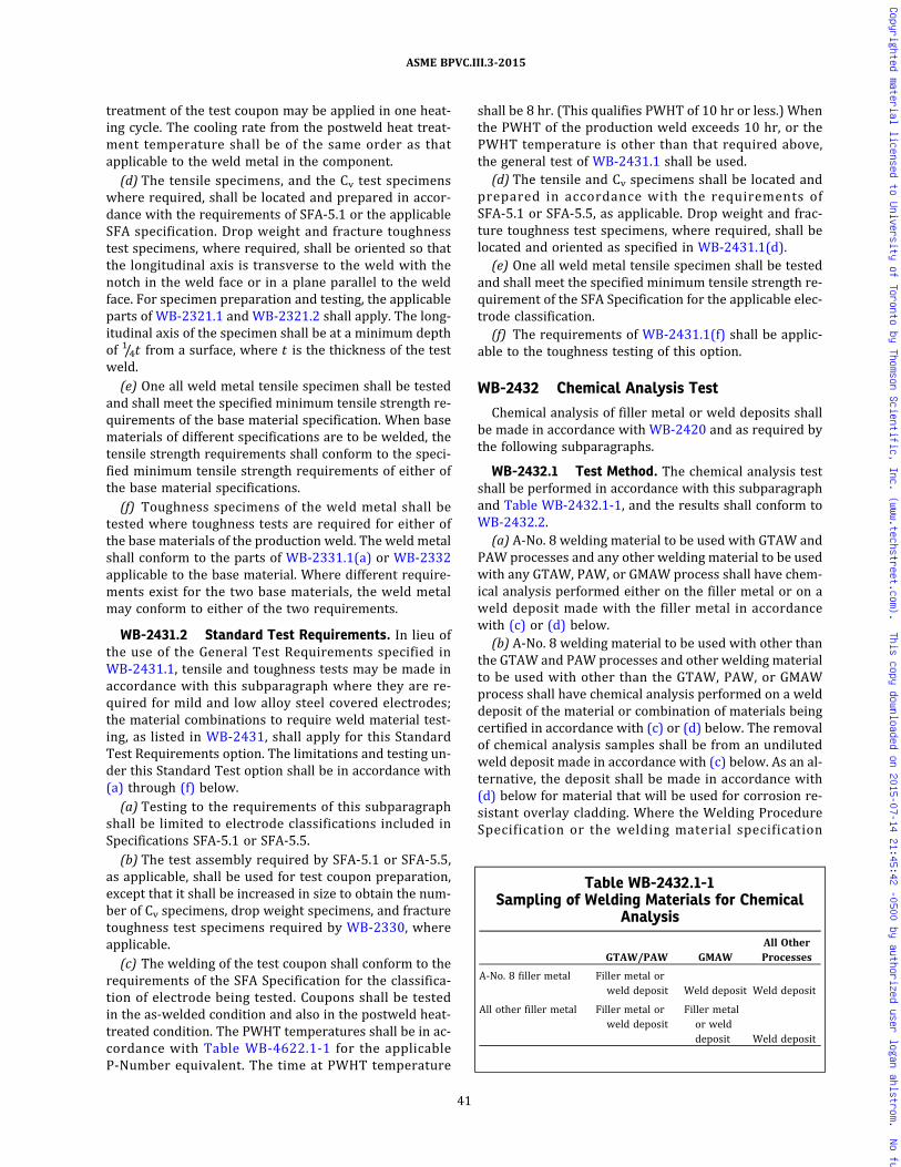
treatment of the test coupon may be applied in one heat-ing cycle. The cooling rate from the postweld heat treat-ment temperature shall be of the same order as thatapplicable to the weld metal in the component.
(d) The tensile specimens, and the Cv test specimenswhere required, shall be located and prepared in accor-dance with the requirements of SFA-5.1 or the applicableSFA specification. Drop weight and fracture toughnesstest specimens, where required, shall be oriented so thatthe longitudinal axis is transverse to the weld with thenotch in the weld face or in a plane parallel to the weldface. For specimen preparation and testing, the applicableparts of WB-2321.1 and WB-2321.2 shall apply. The long-itudinal axis of the specimen shall be at a minimum depthof 1/4t from a surface, where t is the thickness of the testweld.
(e) One all weld metal tensile specimen shall be testedand shall meet the specified minimum tensile strength re-quirements of the base material specification. When basematerials of different specifications are to be welded, thetensile strength requirements shall conform to the speci-fied minimum tensile strength requirements of either ofthe base material specifications.
(f) Toughness specimens of the weld metal shall betested where toughness tests are required for either ofthe base materials of the production weld. The weld metalshall conform to the parts of WB-2331.1(a) or WB-2332applicable to the base material. Where different require-ments exist for the two base materials, the weld metalmay conform to either of the two requirements.
WB-2431.2 Standard Test Requirements. In lieu ofthe use of the General Test Requirements specified inWB-2431.1, tensile and toughness tests may be made inaccordance with this subparagraph where they are re-quired for mild and low alloy steel covered electrodes;the material combinations to require weld material test-ing, as listed in WB-2431, shall apply for this StandardTest Requirements option. The limitations and testing un-der this Standard Test option shall be in accordance with(a) through (f) below.
(a) Testing to the requirements of this subparagraphshall be limited to electrode classifications included inSpecifications SFA-5.1 or SFA-5.5.
(b) The test assembly required by SFA-5.1 or SFA-5.5,as applicable, shall be used for test coupon preparation,except that it shall be increased in size to obtain the num-ber of Cv specimens, drop weight specimens, and fracturetoughness test specimens required by WB-2330, whereapplicable.
(c) The welding of the test coupon shall conform to therequirements of the SFA Specification for the classifica-tion of electrode being tested. Coupons shall be testedin the as‐welded condition and also in the postweld heat-treated condition. The PWHT temperatures shall be in ac-cordance with Table WB-4622.1-1 for the applicableP‐Number equivalent. The time at PWHT temperature
shall be 8 hr. (This qualifies PWHT of 10 hr or less.) Whenthe PWHT of the production weld exceeds 10 hr, or thePWHT temperature is other than that required above,the general test of WB-2431.1 shall be used.
(d) The tensile and Cv specimens shall be located andprepared in accordance with the requirements ofSFA-5.1 or SFA-5.5, as applicable. Drop weight and frac-ture toughness test specimens, where required, shall belocated and oriented as specified in WB-2431.1(d).
(e) One all weld metal tensile specimen shall be testedand shall meet the specified minimum tensile strength re-quirement of the SFA Specification for the applicable elec-trode classification.
(f) The requirements of WB-2431.1(f) shall be applic-able to the toughness testing of this option.
WB-2432 Chemical Analysis Test
Chemical analysis of filler metal or weld deposits shallbe made in accordance with WB-2420 and as required bythe following subparagraphs.
WB-2432.1 Test Method. The chemical analysis testshall be performed in accordance with this subparagraphand Table WB-2432.1-1, and the results shall conform toWB-2432.2.
(a) A‐No. 8 welding material to be used with GTAW andPAW processes and any other welding material to be usedwith any GTAW, PAW, or GMAW process shall have chem-ical analysis performed either on the filler metal or on aweld deposit made with the filler metal in accordancewith (c) or (d) below.
(b) A‐No. 8 welding material to be used with other thanthe GTAW and PAW processes and other welding materialto be used with other than the GTAW, PAW, or GMAWprocess shall have chemical analysis performed on a welddeposit of the material or combination of materials beingcertified in accordance with (c) or (d) below. The removalof chemical analysis samples shall be from an undilutedweld deposit made in accordance with (c) below. As an al-ternative, the deposit shall be made in accordance with(d) below for material that will be used for corrosion re-sistant overlay cladding. Where the Welding ProcedureSpecification or the welding material specification
Table WB-2432.1-1Sampling of Welding Materials for Chemical
Analysis
GTAW/PAW GMAWAll OtherProcesses
A‐No. 8 filler metal Filler metal orweld deposit Weld deposit Weld deposit
All other filler metal Filler metal orweld deposit
Filler metalor welddeposit Weld deposit
41
ASME BPVC.III.3-2015
Copyrighted material licensed to University of Toronto by Thomson Scientific, Inc. (www.techstreet.com). This copy downloaded on 2015-07-14 21:45:42 -0500 by authorized user logan ahlstrom. No further reproduction or distribution is permitted.
specifies percentage composition limits for analysis, itshall state that the specified limits apply for the filler me-tal analysis, the undiluted weld deposit analysis, or in situcladding deposit analysis in conformance with the aboverequired certification testing.
(c) The preparation of samples for chemical analysis ofundiluted weld deposits shall comply with the method gi-ven in the applicable SFA Specification. Where a weld de-posit method is not provided by the SFA specification, thesample shall be removed from a weld pad, groove, orother test weld12 made using the welding process thatwill be followed when the welding material or combina-tion of welding materials being certified is consumed.The weld for A‐No. 8 material to be used with the GMAWprocess shall be made using the shielding gas compositionspecified in the WPSs that will be followed when the ma-terial is consumed. Where a chemical analysis is requiredfor a welding material which does not have a mechanicalproperties test requirement, a chemical analysis test cou-pon shall be prepared as required by WB-2431.1(c), ex-cept that heat treatment of the coupon is not requiredand the weld coupon thickness requirements ofWB-2431.1(c) do not apply.
(d) The alternative method provided in (b) above forthe preparation of samples for chemical analysis of weld-ing material to be used for corrosion resistant overlaycladding shall require a test weld made in accordancewith the essential variables of the WPS that will be fol-lowed when the welding material is consumed. The testweld shall be made in conformance with the require-ments of Section IX, QW‐214.1. The removal of chemicalanalysis samples shall conform with Section IX, TableQW-453 for the minimum thickness for which the weld-ing procedure specification is qualified.
WB-2432.2 Requirements for Chemical Analysis.The chemical elements to be determined, the compositionrequirements of the weld metal, and the recording of re-sults of the chemical analysis shall be in accordance with(a) through (c) below.
(a) See (1) and (2) below.
(1) All welding material of ferrous alloys A‐No. 8 andA‐No. 9 (Section IX, Table QW‐442) shall be analyzed forthe elements listed in Table WB-2432.2-1 and for anyother elements specified in the welding material specifi-cation referenced by the WPS or in the WPS.
(2) All other welding material shall be analyzed forthe elements specified in either the welding materialspecification referenced by the WPS or in the WPS.
(b) The chemical composition of the weld metal or fillermetal shall conform to the welding material specificationfor elements having specified percentage compositionlimits. Where the Welding Procedure Specification con-tains a modification of the composition limits of SFA orother referenced welding material specifications, or pro-vides limits for additional elements, these compositionlimits of the welding procedure specification shall applyfor acceptability.
(c) The results of the chemical analysis shall be re-ported. Elements listed in Table WB-2432.2-1 but notspecified in the welding material specification or WPSshall be reported for information only.
WB-2433 Delta Ferrite Determination
A determination of delta ferrite shall be performed onA‐No. 8 weld material (Section IX, Table QW‐442) backingfiller metal (consumable inserts); bare electrode, rod, orwire filler metal; or weld metal, except that delta ferritedeterminations are not required for SFA-5.9 andSFA-5.4, Type 16‐8‐2, or A‐No. 8 weld filler metal to beused for weld metal cladding.
WB-2433.1 Method. Delta ferrite determinations ofwelding material, including consumable insert material,shall be made using a magnetic measuring instrumentand weld deposits made in accordance with (b) below. Al-ternatively, the delta ferrite determinations for weldingmaterials may be performed by the use of chemical analy-sis of WB-2432 in conjunction with Figure WB-2433.1-1.
(a) Calibration of magnetic instruments shall conformto AWS‐A4.2.
(b) The weld deposit for magnetic delta ferrite determi-nation shall be made in accordance with WB-2432.1(c).
(c) A minimum of six ferrite readings shall be taken onthe surface of the weld deposit. The readings obtainedshall be averaged to a single Ferrite Number (FN).
WB-2433.2 Acceptance Standards. The minimumacceptable delta ferrite shall be 5FN. The results of thedelta ferrite determination shall be included in the Certi-fied Material Test Report of WB-2130 or WB-4120.
WB-2440 STORAGE AND HANDLING OFWELDING MATERIAL
Suitable storage and handling of electrodes, flux, andother welding material shall be maintained. Precautionsshall be taken to minimize absorption of moisture byfluxes and cored, fabricated, and coated electrodes.
Table WB-2432.2-1Chemical Analysis for Welding Material
Materials Elements
Chromium–Nickelstainless steels
C, Cr, Mo, Ni, Mn, Si,Cb + Ta
42
ASME BPVC.III.3-2015
Copyrighted material licensed to University of Toronto by Thomson Scientific, Inc. (www.techstreet.com). This copy downloaded on 2015-07-14 21:45:42 -0500 by authorized user logan ahlstrom. No further reproduction or distribution is permitted.
WB-2500 EXAMINATION AND REPAIR OFCONTAINMENT MATERIAL
WB-2510 EXAMINATION OF CONTAINMENTMATERIAL
(a) Containment material and material welded theretoshall be examined by nondestructive methods applicableto the material and product form as required by the rulesof this subarticle. Seamless pipe, tubes, and fittings NPS 1(DN 25), and less, need not be examined by the rules ofthis subarticle.
(b) The requirements of this subarticle for repair bywelding, including examination of the repair welds, shallbe met wherever repair welds are made to containmentmaterial and material welded thereto. The exceptions in(a) above do not apply to repair welds.
WB-2520 EXAMINATION AFTER QUENCHINGAND TEMPERING
Ferritic steel products that have their properties en-hanced by quenching and tempering shall be examinedby the methods specified in this subarticle for each pro-duct form after the quenching and tempering phase ofthe heat treatment.
WB-2530 EXAMINATION AND REPAIR OF PLATEWB-2531 Required Examination
All plates 2 in. (50 mm) nominal thickness and lessshall be examined by the angle beam ultrasonic methodin accordance with WB-2532.2. All plates greater than2 in. (50 mm) thickness shall be examined by the straightbeam ultrasonic method in accordance with WB-2532.1.
Figure WB-2433.1-1Weld Metal Delta Ferrite Content
18
10
12
14
16
18
10
12
14
16
18
20 22 24
Creq � Cr � Mo � 0.7 Nb
Ni e
q �
Ni �
35
C �
20
N �
0.2
5 C
u
26 28 30
18 20
Ferr
ite n
umbe
r (FN
)0
22 24 26 28 30
2
4
6
8
12
16
18
14
10
20
24
22
26
28
30
35
40
45
50
70
80
90
100
55
65
75
85
95
60
GENERAL NOTES:(a) The actual nitrogen content is preferred. If this is not available, the following applicable nitrogen value shall be used:
(1) GMAW welds — 0.08%, except that when self-shielding flux-cored electrodes are used — 0.12%(2) Welds made using other processes — 0.06%
(b) This diagram is identical to the WRC‐1992 Diagram, except that the solidification mode lines have been removed for ease of use.
43
ASME BPVC.III.3-2015
Copyrighted material licensed to University of Toronto by Thomson Scientific, Inc. (www.techstreet.com). This copy downloaded on 2015-07-14 21:45:42 -0500 by authorized user logan ahlstrom. No further reproduction or distribution is permitted.

WB-2532 Examination ProceduresWB-2532.1 Straight Beam Examination. The re-
quirements for straight beam examination shall be in ac-cordance with SA-578, Specification for Straight BeamWave Ultrasonic Testing and Inspection of Plain and CladSteel Plates for Special Applications, as shown in SectionV, except that the extent of examination and the accep-tance standards to be applied are given in (a) and (b)below.
(a) Extent of Examination. One hundred percent of onemajor plate surface shall be covered by moving the searchunit in parallel paths with not less than a 10% overlap.
(b) Acceptance Standards
(1) Any area where one or more imperfections pro-duce a continuous total loss of back reflection accompa-nied by continuous indications on the same plane thatcannot be encompassed within a circle whose diameteris 3 in. (75 mm) or one‐half of the plate thickness, which-ever is greater, is unacceptable.
(2) In addition, two or more imperfections smallerthan described in (1) above shall be unacceptable unlessseparated by a minimum distance equal to the greatestdiameter of the larger imperfection, or unless they maybe collectively encompassed by the circle described in(1) above.
WB-2532.2 Angle Beam Examination. The require-ments for angle beam examination shall be in accordancewith SA-577, Specification for Ultrasonic Beam Wave In-spection of Steel Plates, as shown in Section V and supple-mented by (a) and (b) below. The calibration notch,extent of examination, and acceptance standards to be ap-plied are given in (a) through (c) below.
(a) Calibration. Angle beam examination shall be cali-brated from a notch.
(b) Extent of Examination. One hundred percent of onemajor plate surface shall be covered by moving the searchunit in parallel paths with not less than 10% overlap.
(c) Acceptance Standards. Material that shows one ormore imperfections which produce indications exceedingin amplitude the indication from the calibration notch isunacceptable unless additional exploration by the straightbeammethod shows the imperfections are laminar in nat-ure and are acceptable in accordance with WB-2532.1(b).
WB-2537 Time of Examination
Acceptance examinations shall be performed at thetime of manufacture as required in (a) through (c) below.
(a) Ultrasonic examination shall be performed afterrolling to size and after heat treatment, except for post-weld heat treatment.
(b) Radiographic examination of repair welds, when re-quired, may be performed prior to any required postweldheat treatment.
(c) Magnetic particle or liquid penetrant examination ofrepair welds shall be performed after final heat treat-ment, except that the examination may be performedprior to postweld heat treatment of P‐No.1 material2 in. (51 mm) and less nominal thickness.
WB-2538 Elimination of Surface Defects
Surface defects shall be removed by grinding or ma-chining, provided the requirements of (a) through (d) be-low are met.(a) The depression, after defect elimination, is blended
uniformly into the surrounding surface.(b) After defect elimination, the area is examined by the
magnetic particle method in accordance with WB-2545or the liquid penetrant method in accordance withWB-2546 to ensure that the defect has been removed orreduced to an imperfection of acceptable size.(c) Areas ground to remove oxide scale or other me-
chanically caused impressions for appearance or to facil-itate proper ultrasonic testing need not be examined bythe magnetic particle or liquid penetrant test method.(d)When the elimination of the defect reduces the
thickness of the section below the minimum required tosatisfy Article WB-3000, the product shall be repairedin accordance with WB-2539.
WB-2539 Repair by Welding
The Material Organization may repair by welding mate-rial from which defects have been removed, provided thedepth of the repair cavity does not exceed one‐third thenominal thickness and the requirements of the followingsubparagraphs are met. Prior approval of the CertificateHolder shall be obtained for the repair of plates to be usedin the manufacture of a containment.
WB-2539.1 Defect Removal. The defect shall be re-moved by suitable mechanical or thermal cutting or gou-ging methods and the cavity prepared for repair(WB-4211.1).
WB-2539.2 Qualification of Welding Proceduresand Welders. The welding procedure and welders orwelding operators shall be qualified in accordance withArticle WB-4000 and Section IX.
WB-2539.3 Blending of Repaired Areas. After repair,the surface shall be blended uniformly into the surround-ing surface.
WB-2539.4 Examination of Repair Welds. Each re-pair weld shall be examined by the magnetic particlemethod (WB-2545) or by the liquid penetrant method(WB-2546). In addition, when the depth of the repair cav-ity exceeds the lesser of 3/8 in. (10 mm) or 10% of the sec-tion thickness, the repair weld shall be radiographed afterrepair in accordance with WB-5110 and to the acceptancestandards of WB-5320. The penetrameter and the
44
ASME BPVC.III.3-2015
Copyrighted material licensed to University of Toronto by Thomson Scientific, Inc. (www.techstreet.com). This copy downloaded on 2015-07-14 21:45:42 -0500 by authorized user logan ahlstrom. No further reproduction or distribution is permitted.
acceptance standards for radiographic examination of re-pair welds shall be based on the section thickness at therepair area.
WB-2539.5 Heat Treatment After Repairs. The pro-duct shall be heat-treated after repair in accordance withthe heat treatment requirements of WB-4620.
WB-2539.6 Material Report Describing Defects andRepairs. Each defect repair exceeding in depth the lesserof 3/8 in. (10 mm) or 10% of the section thickness shall bedescribed in the Certified Material Test Report. The Certi-fied Material Test Report for each piece shall include achart which shows the location and size of the preparedcavity, the welding material identification, the weldingprocedure, the heat treatment, and the examination re-sults, including radiographs.
WB-2539.7 Repair of Cladding by Welding. The Ma-terial Organization may repair defects in cladding bywelding, provided the requirements of (a) through (d) be-low are met.
(a) Qualification of Welding Procedures and Welders.The welding procedure and the welders or welding op-erators shall be qualified in accordance with ArticleWB-4000 and with Section IX.
(b) Defect Removal and Examination of Cavity. The de-fect shall be removed, and the cavity prepared for repairshall be examined by the liquid penetrant method(WB-2546).
(c) Examination of Repaired Areas. The repaired areashall be examined by a liquid penetrant method(WB-2546).
(d) Report of Repairs. Each defect repair shall be de-scribed in the Certified Material Test Report for eachpiece, including a chart which shows the location and sizeof the repair, the welding material identification, weldingprocedure, heat treatment, and examination results.
WB-2540 EXAMINATION AND REPAIR OFFORGINGS AND BARS
WB-2541 Required Examinations
(a) Forgings and bars shall be examined by the ultraso-nic method in accordance with WB-2542, except forgingsor sections of forgings which have coarse grains, or con-figurations which do not yield meaningful examinationresults by ultrasonic methods, shall be examined byradiographic methods in accordance with Section V,Article 2, using the acceptance standards of WB-5320.In addition, all external surfaces and accessible internalsurfaces shall be examined by a magnetic particle method(WB-2545) or a liquid penetrant method (WB-2546).
(b) Forged flanges and fittings, such as elbows, tees,and couplings, shall be examined in accordance with therequirements of WB-2550.
(c) Bar material used for bolting shall be examined inaccordance with WB-2580.
(d) Forgings and forged or rolled bars which are to bebored to form tubular products or fittings shall be exam-ined in accordance with the requirements of WB-2550after boring.
WB-2542 Ultrasonic ExaminationWB-2542.1 Examination Procedure. All forgings in
the rough‐forged or finished condition, and bars, shallbe examined in accordance with Section V, Article 5 andthe following supplemental requirements. The techniquesof (a) through (d) below are required, as applicable.
(a) Forgings may be examined by the use of alternativeultrasonic methods which utilize distance amplitude cor-rections, provided the acceptance standards are shown tobe equivalent to those listed in WB-2542.2.
(b) Cylindrical section bars shall be scanned from theentire external circumference.
(c) Noncylindrical section bars shall be scanned in twoperpendicular directions to the maximum extent possible(through each pair of parallel sides).
(d) Bar products do not require recording and report-ing of indications smaller than the acceptance standard,except when so specified for specialized applications.
WB-2542.2 Acceptance Standards.(a) Straight Beam General Rule. A forging shall be unac-
ceptable if the results of straight beam examinationsshow one or more reflectors which produce indicationsaccompanied by a complete loss of back reflection not as-sociated with or attributable to geometric configurations.Complete loss of back reflection is assumed when theback reflection falls below 5% of full calibration screenheight.
(b) Straight Beam Special Rule for Containment ShellSections
(1) A ring forging made to fine grain melting practiceand used for containment shell sections shall be unaccep-table if the results of the straight beam radial examinationshow one or more reflectors producing a continuous com-plete loss of back reflection accompanied by continuousindications on the same plane that cannot be encom-passed with a circle whose diameter is 3 in. (75 mm) orone‐half of the wall thickness, whichever is greater.
(2) In addition, two or more reflectors smaller thandescribed in (1) above shall be unacceptable unless sepa-rated by a minimum distance equal to the greatest dia-meter of the larger reflector or unless they may becollectively encompassed by the circle described in (1)above.
(c) Angle Beam Rule. A forging shall be unacceptable ifthe results of angle beam examinations show one or morereflectors which produce indications exceeding in ampli-tude the indication from the appropriate calibrationnotches.
45
ASME BPVC.III.3-2015
Copyrighted material licensed to University of Toronto by Thomson Scientific, Inc. (www.techstreet.com). This copy downloaded on 2015-07-14 21:45:42 -0500 by authorized user logan ahlstrom. No further reproduction or distribution is permitted.
WB-2545 Magnetic Particle ExaminationWB-2545.1 Examination Procedure. The procedure
for magnetic particle examination shall be in accordancewith the methods of Section V, Article 7.
WB-2545.2 Evaluation of Indications.(a)Mechanical discontinuities at the surface are re-
vealed by the retention of the examination medium. All in-dications are not necessarily defects, however, sincecertain metallurgical discontinuities and magnetic perme-ability variations may produce similar indications whichare not relevant.(b) Any indication in excess of the WB-2545.3 accep-
tance standards, which is believed to be nonrelevant, shallbe reexamined by the same or other nondestructive ex-amination methods to verify whether or not actual de-fects are present. Surface conditioning may precede thereexamination. Nonrelevant indications which wouldmask defects are unacceptable.(c) Relevant indications are indications which result
from imperfections. Linear indications are indications inwhich the length is more than three times the width.Rounded indications are indications which are circularor elliptical with the length equal to or less than threetimes the width.
WB-2545.3 Acceptance Standards.(a) Only imperfections producing indications with ma-
jor dimensions greater than 1/16 in. (1.5 mm) shall be con-sidered relevant imperfections.(b) Imperfections producing the following indications
are unacceptable:(1) any linear indications greater than 1/16 in.
(1.5 mm) long for material less than 5/8 in. (16 mm) thick,greater than 1/8 in. (3 mm) long for material from 5/8 in.(16 mm) thick to under 2 in. (50 mm) thick, and 3/16 in.(5 mm) long for material 2 in. (50 mm) thick and greater;
(2) rounded indications with dimensions greaterthan 1/8 in. (3 mm) for thicknesses less than 5/8 in.(16 mm) and greater than 3/16 in. (5 mm) for thicknesses5/8 in. (16 mm) and greater;
(3) four or more indications in a line separated by1/16 in. (1.5 mm) or less edge to edge;
(4) ten or more indications in any 6 in.2 (4 000 mm2)of area whose major dimension is no more than 6 in.(150 mm) with the dimensions taken in the most unfavor-able location relative to the indications being evaluated.
WB-2546 Liquid Penetrant ExaminationWB-2546.1 Examination Procedure. The procedure
for liquid penetrant examination shall be in accordancewith the methods of Section V, Article 6.
WB-2546.2 Evaluation of Indications.(a)Mechanical discontinuities at the surface are re-
vealed by bleeding out of the penetrant; however, loca-lized surface discontinuities, such as may occur from
machining marks, surface conditions, or an incompletebond between base metal and cladding, may produce sim-ilar indications which are not relevant.(b) Any indication in excess of the WB-2546.3 accep-
tance standards, which is believed to be nonrelevant, shallbe reexamined to verify whether or not actual defects arepresent. Surface conditioning may precede the reexami-nation. Nonrelevant indications and broad areas of pig-mentation, which would mask defects, are unacceptable.(c) Relevant indications are indications which result
from imperfections. Linear indications are indications inwhich the length is more than three times the width.Rounded indications are indications which are circularor elliptical with the length equal to or less than threetimes the width.
WB-2546.3 Acceptance Standards.(a) Only imperfections producing indications with ma-
jor dimensions greater than 1/16 in. (1.5 mm) shall be con-sidered relevant imperfections.
(b) Imperfections producing the following indicationsare unacceptable:
(1) any linear indications greater than 1/16 in.(1.5 mm) long for material less than 5/8 in. (16 mm) thick,greater than 1/8 in. (3 mm) long for material from 5/8 in.(16 mm) thick to under 2 in. (50 mm) thick, and 3/16 in.(5 mm) long for material 2 in. (50 mm) thick and greater;
(2) rounded indications with dimensions greaterthan 1/8 in. (3 mm) for thicknesses less than 5/8 in.(16 mm) and greater than 3/16 in. (5 mm) for thicknesses5/8 in. (16 mm) and greater;
(3) four or more indications in a line separated by1/16 in. (1.5 mm) or less edge to edge;
(4) ten or more indications in any 6 in.2 (4 000 mm2)of area whose major dimension is no more than 6 in.(150 mm) with the dimensions taken in the most unfavor-able location relative to the indications being evaluated.
WB-2547 Time of Examination
Acceptance examinations, including those for repairwelds, shall be performed at the time of manufacture asrequired in (a) through (d) below.(a) Ultrasonic examination may be performed at any
time after forging [WB-2541(d)], and the maximum prac-tical volume, including weld repairs, if required, shall beexamined after final heat treatment, excluding postweldheat treatment.
(b) Radiographic examination of repair welds, if re-quired, may be performed prior to any required postweldheat treatment.(c) Magnetic particle or liquid penetrant examination
shall be performed in the finished condition, except repairwelds of P‐No. 1 material, 2 in. (50 mm) nominal thick-ness and less, may be examined prior to postweld heattreatment.
46
ASME BPVC.III.3-2015
Copyrighted material licensed to University of Toronto by Thomson Scientific, Inc. (www.techstreet.com). This copy downloaded on 2015-07-14 21:45:42 -0500 by authorized user logan ahlstrom. No further reproduction or distribution is permitted.

(d) Forgings and rolled bars which are to be bored orturned to form tubular parts or fittings shall be examinedafter boring or turning, except for threading.
WB-2548 Elimination of Surface Defects
Elimination of surface defects shall be made in accor-dance with WB-2538.
WB-2549 Repair by Welding
Repair by welding shall be in accordance withWB-2539, except that:
(a) the depth of repair that is permitted is not limited;and
(b) for ferritic steel forgings, the completed repair maybe examined by the ultrasonic method in accordance withthe requirements of WB-2542 in lieu of radiography.
WB-2550 EXAMINATION AND REPAIR OFSEAMLESS AND WELDED TUBULARPRODUCTS AND FITTINGS
WB-2551 Required Examination
In addition to the requirements of the material specifi-cation and of this Article, seamless and welded tubularproducts (including pipe flanges and fittings machinedfrom forgings and bars) shall comply with the following.
(a)Wrought seamless and welded pipe and tubing shallbe examined over the entire volume13 of the material inaccordance with (1), (2), or (3), as follows. Tubular pro-ducts may require both outside and inside surface condi-tioning prior to examination.
(1) Pipe and Tubing(-a) Pipe and tubing smaller than 21/2 in. (64 mm)
O.D. shall be examined by the ultrasonic method in accor-dance with WB-2552.1(a) in two opposite circumferentialdirections14 and by the eddy current method in accor-dance with WB-2554, provided the product is limited tosizes, materials, and thicknesses for which meaningful re-sults can be obtained by eddy current examination as evi-denced by detection of required standards. Each methodshall be calibrated to the appropriate standard: that is,the ultrasonic method shall be calibrated to the axialnotches or grooves of WB-2552.1(b), and the eddy cur-rent method shall be calibrated to the circumferentialnotches and grooves as well as the radial hole ofWB-2554.2.
(-b) As an alternative to the eddy current exami-nation or when the eddy current examination does notyield meaningful results, an axial scan ultrasonic exami-nation in two opposite axial directions,14 in accordancewith WB-2552.1(b), shall be made.
(2) Pipe and tubing 21/2 in. (64 mm) O.D. and largershall be examined by the ultrasonic method in accordancewith WB-2552.1(a) in two opposite circumferential direc-tions, and in accordance with WB-2552.1(b) in two oppo-site axial directions. Alternatively, for welded withoutfiller metal pipe larger than 63/4 in. (170 mm) O.D., the
plate shall be examined by the ultrasonic method in ac-cordance with WB-2530 prior to forming and the weldshall be examined by the radiographic method in accor-dance with WB-2553. Radiographic examination of welds,including repair welds, shall be performed after final roll-ing and forming and may be performed prior to any re-quired postweld heat treatment.
(3) Copper–nickel alloy and nickel alloy seamlesspipe and tubing shall be examined as follows.
(-a) Each pipe and tube, all sizes shall be ultraso-nically examined in accordance with WB-2552.1(a) intwo opposite circumferential directions.
(-b) Pipe and tubing smaller than 21/2 in. (64 mm)O.D. shall be examined by the eddy current method in ac-cordance with WB-2554 if meaningful indications can beobtained from the reference specimen notches. If mean-ingful indications cannot be obtained from the referencespecimen, an axial scan ultrasonic examination in two op-posite axial directions, in accordance with WB-2552.1(b),shall be made.
(-c) Pipe and tubing 21/2 in. (64 mm) O.D. and larg-er shall be examined by an axial scan ultrasonic examina-tion in two opposite axial directions in accordance withWB-2552.1(b).
(b)Wrought seamless and welded without filler metalfittings (including pipe flanges and fittings machined fromforgings and bars) shall be examined in accordance withthe material specification, and in addition by the magneticparticle method in accordance with WB-2555, or the li-quid penetrant method in accordance with WB-2556 onall external surfaces and all accessible internal surfaces(excluding bolt holes and threads). Additionally, for fit-tings over NPS 6 (DN 150), the entire volume shall be ex-amined by the ultrasonic method, if feasible, inaccordance with WB-2552, or the radiographic methodin accordance withWB-2553. Alternatively, the plate shallbe examined by the ultrasonic method in accordance withWB-2530 prior to forming and the weld shall be exam-ined by the radiographic method in accordance withWB-2553. Radiographic examination of welds, includingrepair welds, shall be performed after final rolling andforming, and may be performed prior to any requiredpostweld heat treatment.
WB-2552 Ultrasonic Examination14
WB-2552.1 Examination Procedure for Pipe andTubing. Independent channels or instruments shall beemployed for circumferential and axial scans.
(a) Circumferential Direction. The procedure for ultra-sonic examination of pipe and tubing in the circumferen-tial direction shall be in accordance with SE-213 except asrequired in WB-2551(a)(1), WB-2551(a)(2), andWB-2551(a)(3)(-a), and the requirements of this para-graph. The procedure shall provide a sensitivity whichwill consistently detect defects that produce indications
47
ASME BPVC.III.3-2015
Copyrighted material licensed to University of Toronto by Thomson Scientific, Inc. (www.techstreet.com). This copy downloaded on 2015-07-14 21:45:42 -0500 by authorized user logan ahlstrom. No further reproduction or distribution is permitted.
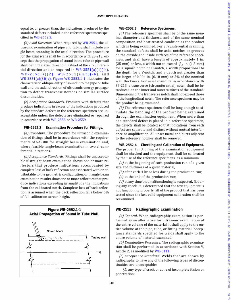
equal to, or greater than, the indications produced by thestandard defects included in the reference specimens spe-cified in WB-2552.3.
(b) Axial Direction. When required by WB-2551, the ul-trasonic examination of pipe and tubing shall include an-gle beam scanning in the axial direction. The procedurefor the axial scans shall be in accordance with SE-213, ex-cept that the propagation of sound in the tube or pipe wallshall be in the axial direction instead of the circumferen-tial direction and as required in WB-2551(a)(1)(-b),W B - 2 5 5 1 ( a ) ( 2 ) , W B - 2 5 5 1 ( a ) ( 3 ) ( - b ) , a n dWB-2551(a)(3)(-c). Figure WB-2552.1-1 illustrates thecharacteristic oblique entry of sound into the pipe or tubewall and the axial direction of ultrasonic energy propaga-tion to detect transverse notches or similar surfacediscontinuities.
(c) Acceptance Standards. Products with defects thatproduce indications in excess of the indications producedby the standard defects in the reference specimen are un-acceptable unless the defects are eliminated or repairedin accordance with WB-2558 or WB-2559.
WB-2552.2 Examination Procedure for Fittings.
(a) Procedure. The procedure for ultrasonic examina-tion of fittings shall be in accordance with the require-ments of SA-388 for straight beam examination and,where feasible, angle‐beam examination in two circum-ferential directions.
(b) Acceptance Standards. Fittings shall be unaccepta-ble if straight beam examination shows one or more re-flectors that produce indications accompanied bycomplete loss of back reflection not associated with or at-tributable to the geometric configuration, or if angle beamexamination results show one or more reflectors that pro-duce indications exceeding in amplitude the indicationsfrom the calibrated notch. Complete loss of back reflec-tion is assumed when the back reflection falls below 5%of full calibration screen height.
WB-2552.3 Reference Specimens.(a) The reference specimen shall be of the same nom-
inal diameter and thickness, and of the same nominalcomposition and heat-treated condition as the productwhich is being examined. For circumferential scanning,the standard defects shall be axial notches or grooveson the outside and inside surfaces of the reference speci-men, and shall have a length of approximately 1 in.(25 mm) or less, a width not to exceed 1/16 in. (1.5 mm)for a square notch or U‐notch, a width proportional tothe depth for a V‐notch, and a depth not greater thanthe larger of 0.004 in. (0.10 mm) or 5% of the nominalwall thickness. For axial scanning in accordance withSE-213, a transverse (circumferential) notch shall be in-troduced on the inner and outer surfaces of the standard.Dimensions of the transverse notch shall not exceed thoseof the longitudinal notch. The reference specimen may bethe product being examined.(b) The reference specimen shall be long enough to si-
mulate the handling of the product being examinedthrough the examination equipment. When more thanone standard defect is placed in a reference specimen,the defects shall be located so that indications from eachdefect are separate and distinct without mutual interfer-ence or amplification. All upset metal and burrs adjacentto the reference notches shall be removed.
WB-2552.4 Checking and Calibration of Equipment.The proper functioning of the examination equipmentshall be checked and the equipment shall be calibratedby the use of the reference specimens, as a minimum(a) at the beginning of each production run of a given
size and thickness of a given material;(b) after each 4 hr or less during the production run;(c) at the end of the production run;(d) at any time that malfunctioning is suspected. If, dur-
ing any check, it is determined that the test equipment isnot functioning properly, all of the product that has beentested since the last valid equipment calibration shall bereexamined.
WB-2553 Radiographic Examination
(a) General. When radiographic examination is per-formed as an alternative for ultrasonic examination ofthe entire volume of the material, it shall apply to the en-tire volume of the pipe, tube, or fitting material. Accep-tance standards specified for welds shall apply to theentire volume of material examined.(b) Examination Procedure. The radiographic examina-
tion shall be performed in accordance with Section V,Article 2, as modified by WB-5111.(c) Acceptance Standard. Welds that are shown by
radiography to have any of the following types of discon-tinuities are unacceptable:
(1) any type of crack or zone of incomplete fusion orpenetration;
Figure WB-2552.1-1Axial Propagation of Sound in Tube Wall
48
ASME BPVC.III.3-2015
Copyrighted material licensed to University of Toronto by Thomson Scientific, Inc. (www.techstreet.com). This copy downloaded on 2015-07-14 21:45:42 -0500 by authorized user logan ahlstrom. No further reproduction or distribution is permitted.

(2) any other elongated indication which has a lengthgreater than:
(-a) 1/4 in. for t up to 3/4 in. (6 mm to 19 mm),inclusive
(-b) 1/3t for t from 3/4 in. to 21/4 in., inclusive(19 mm to 57 mm)
(-c) 3/4 in. for t over 21/4 in. (19 mm to 57 mm)
where t is the thickness of the thinner portion ofthe weld;
(3) any group of aligned indications having an aggre-gate length greater than t in a length of 12t , unless theminimum distance between successive indications ex-ceeds 6L , in which case the aggregate length is unlimited,L being the length of the largest indication;
(4) rounded indications in excess of that shown asacceptable in Section III Appendices, Mandatory Appen-dix VI.
WB-2554 Eddy Current Examination
This examination method is restricted to materials withuniformmagnetic properties and of sizes for which mean-ingful results can be obtained.
WB-2554.1 Examination Procedure. The procedurefor eddy current examination shall provide a sensitivitythat will consistently detect defects by comparison withthe standard defects included in the reference specimenspecified in WB-2554.2. Products with defects that pro-duce indications in excess of the reference standardsare unacceptable unless the defects are eliminated or re-paired in accordance with WB-2558 or WB-2559 asapplicable.
WB-2554.2 Reference Specimens. The referencespecimen shall be of the same nominal diameter andthickness, and of the same nominal composition and heat-treated condition as the product that is being examined.The standard shall contain tangential or circumferentialnotches on the outside surface plus a 1/16 in. (1.5 mm) dia-meter hole drilled through the wall. For copper–nickel al-loy and nickel alloy materials, the standard shall have onenotch extending circumferentially on the outside surfaceand one notch extending circumferentially on the insidesurface plus a 1/16 in. (1.5 mm) diameter hole drilledthrough the wall. These shall be used to establish the re-jection level for the product to be tested. The referencenotches shall have a depth not greater than the larger of0.004 in. (0.10 mm) or 5% of the wall thickness. Thewidth of the notch shall not exceed 1/16 in. (1.5 mm).The length shall be approximately 1 in. (25 mm) or less.The size of reference specimens shall be as specified inWB-2552.3.
WB-2554.3 Checking and Calibration of Equipment.The checking and calibration of examination equipmentshall be the same as in WB-2552.4.
WB-2555 Magnetic Particle Examination
Magnetic particle examination shall be performed in ac-cordance with the requirements of WB-2545.
WB-2556 Liquid Penetrant Examination
Liquid penetrant examination shall be performed in ac-cordance with the requirements of WB-2546.
WB-2557 Time of Examination
(a) Products that are quenched and tempered shall beexamined, as required, after the quenching and temperingheat treatment.
(b) Products that are not quenched and tempered shallreceive the required examinations as follows:
(1) Ultrasonic or eddy current examination, when re-quired, shall be performed after final heat treatment, ex-cept postweld heat treatment.
(2) Radiographic examination, when required, maybe performed prior to any required postweld heattreatment.
(3)Magnetic particle or liquid penetrant examina-tion, including repair welds, shall be performed after finalheat treatment, except that the examination may be per-formed prior to postweld heat treatment for P‐No. 1 (Sec-tion IX of the Code) materials of 2 in. (50 mm) and lessnominal thickness.
(4) Forgings and rolled bars which are to be boredand/or turned to form tubular parts or fittings shall be ex-amined after boring and/or turning, except for threading.Fittings shall be examined after final forming.
WB-2558 Elimination of Surface Defects
Surface defects shall be removed by grinding or ma-chining, provided the requirements of (a) through (c) be-low are met.
(a) The depression, after defect elimination, is blendeduniformly into the surrounding surface.
(b) After defect elimination, the area is examined by themethod which originally disclosed the defect to assurethat the defect has been removed or reduced to an imper-fection of acceptable size.
(c) If the elimination of the defect reduces the thicknessof the section below the minimum required to satisfy therules of Article WB-3000, the product shall be repaired inaccordance with WB-2559.
WB-2559 Repair by Welding
Repair of defects shall be in accordance with WB-2539,except repair by welding is not permitted on copper–nickel alloy and nickel alloy materials.
49
ASME BPVC.III.3-2015
Copyrighted material licensed to University of Toronto by Thomson Scientific, Inc. (www.techstreet.com). This copy downloaded on 2015-07-14 21:45:42 -0500 by authorized user logan ahlstrom. No further reproduction or distribution is permitted.

WB-2570 EXAMINATION AND REPAIR OF CASTPRODUCTS
WB-2571 Required ExaminationFor examination of the containment casting, the follow-
ing shall apply:(a) All cast products shall be examined by the ultraso-
nic method as specified in WB-2574.(b) All external and accessible internal surfaces, except
threaded surfaces, shall be examined using either the li-quid penetrant method (WB-2576) or the magnetic parti-cle method (WB-2577).
WB-2572 Time of Nondestructive ExaminationAll examinations shall be performed after final machin-
ing except that ultrasonic testing shall be performed atthe time when the configuration is best suited for scan-ning and the most meaningful results can be obtained.
WB-2573 Provisions for Repair of Base Materialby Welding
Castings shall not be repaired by plugging, welding,brazing, impregnation, or any other means.
WB-2574 Ultrasonic Examination of CastingsUltrasonic examination shall be performed in accor-
dance with Section V, Article 5, T-571.4. Each manufac-turer shall certify that the procedure is in accordancewith the following requirements and shall make the pro-cedure available for approval upon request.The following acceptance standards shall be applied:(a) The Quality Levels of SA-609 as shown in Section V
shall apply for the casting thickness indicated.(1) Quality Level 1 for thicknesses up to 2 in.
(50 mm)(2) Quality Level 3 for thicknesses 2 in. to 4 in.
(50 mm to 100 mm)(3) Quality Level 4 for thicknesses greater than 4 in.
(100 mm)(b) In addition to the Quality Level requirements stated
in (a) above, the requirements in (1) through (5) belowshall apply for both straight beam and angle beamexamination.
(1) Areas giving indications exceeding the AmplitudeReference Line with any dimension longer than those spe-cified in the following tabulation shall be unacceptable:
UT Quality LevelLongest Dimension of Area, in. (mm)
[Notes (1), (2), and (3)]
1 1.5 (38)2 2.0 (50)3 2.5 (64)4 3.0 (75)
Table continued
NOTES:(1) The areas for the Ultrasonic Quality Levels in SA-609
refer to the surface area on the casting over whichcontinuous indication, exceeding the transfer-corrected distance amplitude curve, is maintained.
(2) Areas shall be measured from dimensions of themovement of the search unit, using the center of thesearch unit as the reference point.
(3) In certain castings, because of very long metal pathdistances or curvature of the examination surfaces,the surface area over which a given discontinuity isdetected may be considerably larger or smaller thanthe actual area of the discontinuity in the casting; insuch cases, other criteria that incorporate a considera-tion of beam angles or beam spread shall be used forrealistic evaluation of the discontinuity.
(2) Quality Level 1 shall apply for the volume of cast-ings within 1 in. (25 mm) of the surface regardless of theoverall thickness.
(3) Discontinuities indicated to have a change indepth equal to or greater than one-half the wall thicknessor 1 in. (25 mm), whichever is less, shall be unacceptable.
(4) Two or more indications in the same plane withamplitudes exceeding the Amplitude Reference Line andseparated by a distance less than the longest dimensionof the larger of the adjacent indications shall be unaccep-table if they cannot be encompassed within an area lessthan that of the Quality Level specified in (1).
(5) Two or more indications greater than permittedfor Quality Level 1 for castings less than 2 in. (50 mm)in thickness, greater than permitted for Quality Level 2f o r t h i c kne s s e s 2 i n . t h r ou gh 4 i n . ( 50 mmthrough 100 mm), and greater than permitted for QualityLevel 3 for thicknesses greater than 4 in. (100 mm), sepa-rated by a distance less than the longest dimension of thelarger of the adjacent indications, shall be unacceptable ifthey cannot be encompassed in an area less than that ofthe Quality Level requirements stated in (1).
WB-2576 Liquid Penetrant Examination(a) Castings shall be examined, if required, on all acces-
sible surfaces by the liquid penetrant method in accor-dance with Section V of the Code.(b) Evaluation of Indications. All indications shall be
evaluated in terms of the acceptance standards. Mechan-ical discontinuities intersecting the surface are indicatedby bleeding out of the penetrant; however, localized sur-face discontinuities as may occur from machining marks,scale, or dents may produce indications that are not rele-vant. Any indication in excess of the acceptance standardsbelieved to be nonrelevant shall be regarded as a defectuntil it is reexamined to verify whether actual defectsare present. Nonrelevant indications and broad areas ofpigmentation that would mask indications of defects areunacceptable. Surface conditioning may precede the reex-amination. Relevant indications are those that result frommechanical discontinuities. Linear indications are those
50
ASME BPVC.III.3-2015
Copyrighted material licensed to University of Toronto by Thomson Scientific, Inc. (www.techstreet.com). This copy downloaded on 2015-07-14 21:45:42 -0500 by authorized user logan ahlstrom. No further reproduction or distribution is permitted.
whose length is more than 3 times the width. Rounded in-dications are those that are circular or elliptical with thelength less than 3 times the width. Indications with majordimensions greater than 1/16 in. (1.5 mm) are consideredrelevant.
(c) Acceptance Standards. The following relevant indi-cations are unacceptable:
(1) any linear indications greater than 1/16 in.(1.5 mm) long for materials less than 5/8 in. (16 mm) thick,greater than 1/8 in. (3 mm) long for materials from 5/8 in.(16 mm) thick to under 2 in. (50 mm) thick, and 3/16 in.(5 mm) long for materials 2 in. (50 mm) thick and greater
(2) rounded indications with dimensions greaterthan 1/8 in. (3 mm) for thicknesses less than 5/8 in.(16 mm) and greater than 3/16 in. (5 mm) for thicknesses5/8 in. (16 mm) and greater
(3) four or more relevant indications in a line sepa-rated by 1/16 in. (1.5 mm) or less edge-to-edge
(4) ten or more relevant indications in any 6 in.2
(4 000 mm2) of surface with the major dimension of thisarea not to exceed 6 in. (150 mm) taken in the most un-favorable orientation relative to the indications beingevaluated
WB-2577 Magnetic Particle Examination (forDuctile Cast Iron)
(a) Castings of magnetic material shall be examined, ifrequired, on all accessible surfaces by a magnetic particlemethod in accordance with Section V of the Code.
(b) Evaluation of Indications. All indications shall beevaluated in terms of the acceptance standards. Mechan-ical discontinuities intersecting the surface are indicatedby retention of the examination medium. All indicationsare not necessarily defects since certain metallurgical dis-continuities and magnetic permeability variations mayproduce indications that are not relevant. Any indicationin excess of the acceptance standards that is believed tobe nonrelevant shall be regarded as a defect until it is re-examined to verify whether actual defects are present.Nonrelevant indications that would mask indications ofdefects are unacceptable. Surface conditioning may pre-cede the reexamination. Relevant indications are thosethat result from unacceptable mechanical discontinuitiesand have a major dimension greater than 1/16 in.(1.5 mm). Linear indications are those whose length ismore than 3 times the width. Rounded indications arethose that are circular or elliptical with the length lessthan 3 times the width.
(c) Acceptance Standards. The following relevant indi-cations are unacceptable:
(1) linear indications greater than 1/16 in. (1.5 mm)long for materials less than 5/8 in. (16 mm) thick, greaterthan 1/8 in. (3 mm) long for materials from 5/8 in. (16 mm)thick to under 2 in. (50 mm) thick, and 3/16 in. (5 mm) longfor materials 2 in. (50 mm) thick and greater
(2) rounded indications with dimensions greaterthan 1/8 in. (3 mm) long for materials from 5/8 in.(16 mm) thick to under 2 in. (50 mm) thick, and 3/16 in.(5 mm) long for materials 2 in. (50 mm) thick and greater
(3) four or more relevant indications in a line sepa-rated by 1/16 in. (1.5 mm) or less edge-to-edge
(4) ten or more relevant indications in any 6 in.2
(4 000 mm2) of surface with the major dimension of thisarea not to exceed 6 in. (150 mm) taken in the most un-favorable orientation relative to the indications beingevaluated
WB-2580 EXAMINATION OF BOLTS, STUDS, ANDNUTS
WB-2581 Required Examination
All bolting material shall be visually examined in accor-dance with WB-2582. Nominal sizes greater than 1 in.(25 mm) shall be examined by either the magnetic parti-cle or the liquid penetrant method. In addition, nominalsizes greater than 2 in. (50 mm) but not over 4 in.(100 mm) shall be examined by the ultrasonic methodin accordance with WB-2585 and nominal sizes greaterthan 4 in. (100 mm) shall be examined by the ultrasonicmethod in accordance with both WB-2585 and WB-2586.
WB-2582 Visual Examination
The areas of threads, shanks, and heads of final ma-chined parts shall be visually examined. The require-ments o f WB-5520 do not apply to personne lperforming this examination. Harmful discontinuitiessuch as laps, seams, or cracks that would be detrimentalto the intended service are unacceptable.
WB-2583 Magnetic Particle Examination (forFerritic Steel Bolting Material Only)
WB-2583.1 Examination Procedure. All bolts, studs,and nuts greater than 1 in. (25 mm) nominal bolt sizeshall be examined by the magnetic particle method in ac-cordance with ASTM A275. If desired, the supplier mayperform liquid penetrant examination in accordance withWB-2584 instead of magnetic particle examination. Suchexamination shall be performed on the finished compo-nent after threading or on the materials stock at approxi-mately the finished diameter before threading and afterheading (if involved). This examination shall be per-formed on all accessible surfaces.
WB-2583.2 Evaluation of Indications.(a) All indications shall be evaluated in terms of the ac-
ceptance standards. Linear indications are those indica-tions in which the length is more than 3 times thewidth. Rounded indications are those which are circularor elliptical with the length equal to or less than 3 timesthe width.
51
ASME BPVC.III.3-2015
Copyrighted material licensed to University of Toronto by Thomson Scientific, Inc. (www.techstreet.com). This copy downloaded on 2015-07-14 21:45:42 -0500 by authorized user logan ahlstrom. No further reproduction or distribution is permitted.
(b) All indications are not necessarily relevant: leakageof magnetic fields and permeability variations may pro-duce indications that are not relevant to the detectionof unacceptable discontinuities. Indications with majordimensions of 1/16 in. (1.5 mm) or less are not relevant.
(c) Any indication that is believed to be nonrelevant,and that is larger than acceptable, shall be consideredto be a defect and shall be reexamined after light surfaceconditioning.
(d) Any indication observed during such reexaminationshall be considered relevant and shall be evaluated interms of the acceptance standards.
(e) As an alternative to magnetic particle reexamina-tion, other nondestructive examination means (such as li-quid penetrant examination for surface discontinuities)may be used to determine relevancy.
WB-2583.3 Acceptance Standard. Linear nonaxialindications are unacceptable. Linear axial indicationsgreater than 1 in. (25 mm) in length are unacceptable.
WB-2584 Liquid Penetrant ExaminationWB-2584.1 Examination Procedure. All bolts, studs,
and nuts greater than 1 in. (25 mm) nominal bolt sizeshall be examined by a liquid penetrant method in accor-dance with the methods of Section V, Article 6. Such exam-ination shall be performed on the finished componentafter threading or on the materials stock at approximatelythe finished diameter before threading and after heading(if involved).
WB-2584.2 Evaluation of Indications. All indicationsshall be evaluated in terms of the acceptance standards.Linear indications are those indications in which thelength is more than three times the width. Rounded indi-cations are those which are circular to elliptical with thelength equal to or less than three times the width. All pe-netrant indications are not necessarily relevant. Surfaceimperfections such as machining marks and scratchesmay produce indications that are nonrelevant to the de-tection of unacceptable discontinuities. Broad areas ofpigmentation, which could mask indications of defects,are unacceptable. Indications with major dimensions of1/16 in. (1.5 mm) or less are not relevant. Any indicationthat is believed to be nonrelevant, and that is larger thanacceptable, shall be considered to be a defect and shall bereexamined after light surface conditioning. Any area ofpigmentation also shall be reexamined after recleaningor light surface conditioning, as appropriate. Any indica-tion observed during such reexamination shall be consid-ered relevant and shall be evaluated in terms of theacceptance standards.
WB-2584.3 Acceptance Standard. Linear nonaxialindications are unacceptable. Linear axial indicationsgreater than 1 in. (25 mm) long are unacceptable.
WB-2585 Ultrasonic Examination for SizesGreater Than 2 in. (50 mm)
All bolts, studs, and nuts greater than 2 in. (50 mm)nominal bolt size shall be ultrasonically examined overthe entire cylindrical surface prior to threading in accor-dance with the following requirements.
WB-2585.1 Ultrasonic Method. Examination shall becarried out by the straight beam, radial‐scan method inaccordance with Section V, Article 23, SA-388.
WB-2585.2 Examination Procedure. Examinationshall be performed at a nominal frequency of 2.25 MHzwith a search unit not to exceed 1 in.2 (650 mm2).
WB-2585.3 Calibration of Equipment. Calibrationsensitivity shall be established by adjustment of the in-strument so that the first back reflection is 75% to 90%of full‐screen height.
WB-2585.4 Acceptance Standard. Any discontinuitythat causes an indication in excess of 20% of the height ofthe first back reflection or any discontinuity that preventsthe production of a first back reflection of 50% of the ca-libration amplitude is not acceptable.
WB-2586 Ultrasonic Examination for Sizes Over4 in. (100 mm)
In addition to the requirements of WB-2585, all bolts,studs, and nuts over 4 in. (100 mm) nominal bolt sizeshall be ultrasonically examined over the entire surfaceof each end before or after threading in accordance withthe following requirements.
WB-2586.1 Ultrasonic Method. Examination shall becarried out by the straight beam, longitudinal‐scanmethod.
WB-2586.2 Examination Procedure. Examinationshall be performed at a nominal frequency of 2.25 MHzwith a search unit having a circular cross section with adiameter not less than 1/2 in. (13 mm) nor more than11/8 in. (29 mm).
WB-2586.3 Calibration of Equipment. Calibrationshall be established on a test bar of the same nominalcomposition and diameter as the production part and aminimum of one‐half of the length. A 3/8 in. (10 mm) dia-meter by 3 in. (75 mm) deep flat‐bottom hole shall bedrilled in one end of the bar and plugged to full depth.A distance–amplitude curve shall be established by scan-ning from both ends of the test bar.
WB-2586.4 Acceptance Standard. Any discontinuitythat causes an indication in excess of that produced by thecalibration hole in the reference specimen as corrected bythe distance–amplitude curve is not acceptable.
52
ASME BPVC.III.3-2015
Copyrighted material licensed to University of Toronto by Thomson Scientific, Inc. (www.techstreet.com). This copy downloaded on 2015-07-14 21:45:42 -0500 by authorized user logan ahlstrom. No further reproduction or distribution is permitted.
WB-2587 Time of ExaminationAcceptance examinations shall be performed after the
final heat treatment required by the basic materialspecification.
WB-2588 Elimination of Surface DefectsUnacceptable surface defects on finished bolts, studs,
and nuts are not permitted, and are cause for rejection.
WB-2589 Repair by WeldingWeld repairs of bolts, studs, and nuts are not permitted.
WB-2600 MATERIAL ORGANIZATION’SQUALITY SYSTEM PROGRAMS
WB-2610 DOCUMENTATION ANDMAINTENANCE OF QUALITY SYSTEMPROGRAMS
(a) Except as provided in (b) below, Material Organiza-tions shall have a Quality System Program or an Identifi-cation and Verification Program, as applicable, whichmeets the requirements of WA-3800.
(b) The requirements of NCA‐3860 and NCA‐3856 shallbe met as required by WB-2130 and WB-2150, respec-tively. The other requirements of WA-3800 need not be
used by Material Organizations for small products, as de-fined in (c) below, and for material which is allowed bythis Subsection to be furnished with a Certificate of Com-pliance. For these products, the Certificate Holder’s Qual-ity Assurance Program (Article WA-4000) shall includemeasures to provide assurance that the material is furn-ished in accordance with the material specification andwith the applicable requirements of this Subsection.
(c) For the purpose of this paragraph, small productsare defined as given in (1) through (4) below:
(1) pipe, tube, pipe fittings, and flanges NPS 2(DN 50) and less;
(2) bolting material, including studs, nuts, and boltsof 1 in. (25 mm) nominal diameter and less;
(3) bars with a nominal cross‐sectional area of 1 in.2
(650 mm2) and less; and
(4)material for valves with inlet pipe connections ofNPS 2 (DN 50) and less.
WB-2700 DIMENSIONAL STANDARDS
Dimensions of standard items shall comply with thestandards and specifications listed in Article WA-7000.
53
ASME BPVC.III.3-2015
Copyrighted material licensed to University of Toronto by Thomson Scientific, Inc. (www.techstreet.com). This copy downloaded on 2015-07-14 21:45:42 -0500 by authorized user logan ahlstrom. No further reproduction or distribution is permitted.
ð15Þ
ð15Þ
ARTICLE WB-3000DESIGN
WB-3100 GENERAL DESIGN
WB-3110 LOADING CRITERIAWB-3111 Loading Conditions
The loadings considered in designing a containment asidentified in the Design Specification shall include, but arenot limited to those in (a) through (g) below:(a) internal and external pressures(b) impact loads caused by either internal or external
conditions, including drop and puncture(c) weight of the containment and normal contents un-
der operating or test conditions, including additionalpressure due to static and dynamic head of liquids(d) superimposed loads such as other components, op-
erating equipment, impact limiting devices, shielding, in-sulation, and linings(e) shock loads, vibration loads, transportation loads,
and handling loads(f) reaction loads from attachments and supports(g) temperature effects caused by contents, the exter-
nal environment, and other components
WB-3112 Design Loadings
The Design Loadings shall be established in accordancewith WA-2123.1 and the following subparagraphs.
WB-3112.1 Design Pressure. The specified internaland external Design Pressures to be used in this Subsec-t i on sha l l be es tab l i shed in accordance wi thWA-2123.1(a).
WB-3112.2 Design Temperature. The specified De-sign Temperature shall be established in accordance withWA-2123.1(b). It shall be used in computations involvingthe Design Pressure and the coincidental Design Mechan-ical Loads. If necessary, the metal temperature shall bedetermined by computation using accepted heat transferprocedures or by measurement from equipment in ser-vice under equivalent operating conditions. In no caseshall the temperature of the metal exceed the maximumtemperature listed in the applicability column of SectionII, Part D, Subpart 1, Tables 2A, 2B, and 4, nor exceedthe maximum temperature limitations specified else-where in this Subsection.
WB-3112.3 Design Mechanical Loads. The specifiedDesign Mechanical Loads shall be established in accor-dance with WA-2123.1(c). They shall be used in conjunc-tion with the Design Pressure.
WB-3112.4 Design Stress Intensity Values.(a) Design stress intensity values for Section III, Class
TC materials listed in Section II, Part D, Subpart 1, Tables2A, 2B, and 4 shall be used. The materials shall not beused at temperatures that exceed the temperature limitestablished in the stress tables. The stress intensity val-ues in the tables may be interpolated for intermediatetemperatures. As an additional control on permittedtransportation containment materials listed in SectionII, Part D, Subpart 1, Tables 2A and 2B, only the followingmaterials shall be used:
(1)materials whose P-numbers are listed in TableWB-4622.1-1, or
(2) ductile cast iron castings per specificationsSA-874 or SA/JIS G5504 of Section II, Part D, Subpart 1,Table 2A
(b) The design of a containment shall be determined sothat the primary membrane and primary membrane plusbending stress intensities due to any combination of De-sign Loading does not exceed the maximum design stressintensity value permitted at the Design Temperature.These design stress intensity values may be interpolatedfor an intermediate Design Temperature.
WB-3113 Operating and Test Conditions
(a) Transportation containments (WA-1110) are sub-ject to operating and test conditions that are requiredto be considered in the design of the containment in orderto satisfy applicable safety criteria.
(b) The selection of operating and test conditions is be-yond the scope of this Division. The Design Specificationshall specify these conditions using appropriate guidancefrom safety criteria documents for transportation con-tainments and the requirements of regulatory and enfor-cement authorities having jurisdiction.
(c) Each operating and test condition to which the con-tainment may be subjected shall be classified in accor-d a n c e w i t h WA - 2 1 2 0 , a n d S e r v i c e L i m i t s[WA-2123.4(b)] shall be designated in the Design Specifi-cation in such detail as will provide a complete basis fordesign in accordance with this Subsection.
(d)When any loading for which Level A or D ServiceLimits15 are specified in the Design Specification, theyshall be evaluated in accordance with WA-2120 and incompliance with the applicable design and stress inten-sity limits of this Subsection.
54
ASME BPVC.III.3-2015
Copyrighted material licensed to University of Toronto by Thomson Scientific, Inc. (www.techstreet.com). This copy downloaded on 2015-07-14 21:45:42 -0500 by authorized user logan ahlstrom. No further reproduction or distribution is permitted.

ð15Þ
ð15Þ
WB-3114 Stress Limits
Stress limits associated with operating and test condi-tions are specified in WB-3220 and WB-3230.
WB-3120 SPECIAL CONSIDERATIONSWB-3121 Material Degradation
Material subject to thinning by corrosion, erosion, me-chanical abrasion, or other environmental effects shallhave provision made in the Design Specification for theseeffects by indicating the increase in the thickness of thebase metal over that determined by the design analysis(WB-3200). Other suitable methods of protection maybe used. Material added or included for these purposesneed not be of the same thickness for all areas of the con-tainment if different rates of attack are expected for thevarious areas.
WB-3122 Cladding
The rules of this paragraph apply to the design of cladcontainments constructed of materials permitted in Sec-tion II, Part D, Subpart 1, Tables 2A and 2B. Only materialswhose P‐numbers are listed in Table WB-4622.1-1 shallbe used.
WB-3122.1 Primary Stresses. No structural strengthshall be attributed to the cladding.
WB-3122.2 Design Dimensions. The dimensions gi-ven in (a) and (b) below shall be used in the design ofthe containment.
(a) For containments subjected to internal pressure,the inside diameter shall be taken at the nominal innerface of the cladding.
(b) For containments subjected to external pressure,the outside diameter shall be taken at the outer face ofthe base metal.
WB-3122.3 Secondary and Peak Stresses. In satisfy-ing WB-3222.6 and WB-3222.9, the presence of the clad-ding shall be considered with respect to both the thermalanalysis and the stress analysis. The stresses in both ma-terials shall be limited to the values specified inWB-3222.6 and WB-3222.9. However, when the claddingis of the integrally bonded type and the nominal thicknessof the cladding is 10% or less of the total thickness of thecontainment, the presence of the cladding may beneglected.
WB-3122.4 Bearing Str esses. In sat is fy ingWB-3227.1, the presence of cladding shall be included.
WB-3123 WeldingWB-3123.1 Dissimilar Metals. In satisfying the re-
quirements of this subarticle, caution shall be exercisedin design and construction involving dissimilar metalshaving different chemical compositions, mechanical prop-erties, and coefficients of thermal expansion to avoid dif-ficulties in service.
WB-3123.2 Fillet Welded Attachments. Fillet weldsconforming to Figure WB-4427-1 may be used for attach-ments to containments except as limited by WB-4433.Limits for primary and secondary stress intensities inthe weld shall be one‐half of the allowable primary andsecondary stress intensities for the weaker of the materi-als being joined. Evaluation for cyclic loading shall bemade in accordance with WB-3222.9, using a fatiguestrength reduction factor of 4, and shall include consid-eration of temperature differences between the contain-ment and the attachment , and of expansion orcontraction of the containment produced by internal orexternal pressure.
WB-3130 GENERAL DESIGN RULESWB-3131 Design Reports
The Certificate Holder shall provide a Design Reportconforming to the requirements of WA-3352 andWB-3211.
WB-3132 Dimensional Standards for StandardProducts
Dimensions of standard products shall comply with thestandards and specifications listed in Table WA-7100-1when the standard or specification is referenced in thespecific design subarticle. However, compliance withthese standards does not replace or eliminate the require-ments for stress analysis.
WB-3133 External Pressure, Axial Compression,Buckling, and Instability
Rules are given in this paragraph for the considerationof statically applied external pressure and axial compres-sion loads for Design Loadings and normal loadings. Com-pressive loads as a result of accident loadings shall usethe rules from WB-3224.1(e).
WB-3133.1 General. Rules are given in this para-graph for determining the thickness of spherical shells,cylindrical shells with or without stiffening rings, andformed heads under external pressure loading.
WB-3133.2 Nomenclature. The symbols used in thisparagraph are defined as follows:
A = factor determined from Section II, Part D, Subpart3, Figure G and used to enter the applicable materi-al chart in Section II, Part D, Subpart 3. For the caseof cylinders having Do/T values less than 10, seeWB-3133.3(b). Also, factor determined from theapplicable chart in Section II, Part D, Subpart 3for the material used in a stiffening ring, corre-sponding to the factor B and the design metal tem-perature for the shell under consideration.
As = cross‐sectional area of a stiffening ring
55
ASME BPVC.III.3-2015
Copyrighted material licensed to University of Toronto by Thomson Scientific, Inc. (www.techstreet.com). This copy downloaded on 2015-07-14 21:45:42 -0500 by authorized user logan ahlstrom. No further reproduction or distribution is permitted.
ð15Þ
B = factor determined from the applicable chart in Sec-tion II, Part D, Subpart 3 for the material used in ashell or stiffening ring at the design metal tempera-ture, psi (MPa)
Do = outside diameter of the cylindrical shellE = modulus of elasticity of material at Design Tem-
perature, psi (MPa). For external pressure and axialcompression design in accordance with this Sub-section, the modulus of elasticity to be used shallbe taken from the applicable materials chart in Sec-tion II, Part D, Subpart 3. (Interpolation may bemade between lines for intermediate tempera-tures.) The modulus of elasticity values shown inSection II, Part D, Subpart 3 for material groupsmay differ from those values listed in Section II,Part D, Subpart 2, Tables TM for specific materials.Section II, Part D, Subpart 3 values shall be appliedonly to external pressure and axial compressiondesign
I = available moment of inertia of the combined ring‐shell section about its neutral axis, parallel to theaxis of the shell. The width of the shell which is ta-ken as contributing to the combined moment of in-
ertia shall be not greater than 1.10 and shall
be taken as lying one‐half on each side of the cen-troid of the ring. Portions of shell plates shall notbe considered as contributing area to more thanone stiffening ring.
I s = required moment of inertia of the combined ring‐shell section about its neutral axis parallel to theaxis of the shell
L = the design length of a containment taken as the lar-gest of the following:
(a) the distance between head tangent lines plusone‐third of the depth of each head if there are nostiffening rings
(b) the greatest center‐to‐center distance be-tween any two adjacent stiffening rings
(c) the distance from the center of the first stif-fening ring to the head tangent line plus one‐thirdof the depth of the head, all measured parallel tothe axis of the containment
Ls = one‐half the distance from the center line of the stif-fening ring to the next line of support on one side,plus one‐half of the center line distance to the nextline of support on the other side of the stiffeningring, both measured parallel to the axis of the com-ponent. A line of support is one of the following:
(a) a stiffening ring that meets the requirementsof this paragraph
(b) a circumferential line on a head at one‐thirdthe depth of the head from the head tangent line
(c) circumferential connection to a jacket for ajacketed section of a cylindrical shell
P = external Design Pressure, psi (MPa) (gage or abso-lute, as required)
Pa = allowable external pressure, psi (MPa) (gage or ab-solute as required)
R = inside radius of spherical shellS = the lesser of 1.5 times the stress intensity at design
metal temperature from Section II, Part D, Subpart1, Tables 2A and 2B or 0.9 times the tabulated yieldstrength at design metal temperature from SectionII, Part D, Subpart 1, Table Y-1, psi (MPa)
T = minimum required thickness of cylindrical shell orspherical shell
Tn = nominal thickness used, less corrosion allowance,of a cylindrical shell
WB-3133.3 Cylindrical Shells. The thickness of cylin-ders under external pressure shall be determined by theprocedure given in (a) or (b) below.
(a) Cylinders having Do/T values ≥ 10:
Step 1. Assume a value for T and determine the ratiosL/Do and Do/T .
Step 2. Enter Section II, Part D, Subpart 3, Figure G atthe value at L/Do determined in Step 1. For values ofL/Do greater than 50, enter the chart at a value of L/Do
of 50. For values of L/Do less than 0.05, enter the chartat a value of L/Do of 0.05.
Step 3. Move horizontally to the line for the value ofDo/T determined in Step 1. Interpolation may be madefor intermediate values of Do/T . From this point of inter-section move vertically downward to determine the valueof factor A .
Step 4. Using the value of A calculated in Step 3, enterthe applicable material chart in Section II, Part D, Subpart3 for the material under consideration. Move vertically toan intersection with the material/temperature line for theDesign Temperature. Interpolation may be made betweenlines for intermediate temperatures. In cases where thevalue of A falls to the right of the end of the material/tem-perature line, assume an intersection with the horizontalprojection of the upper end of the material/temperatureline. For values of A falling to the left of the material/tem-perature line, see Step 7.
Step 5. From the intersection obtained in Step 4, movehorizontally to the right and read the value of B .
Step 6. Using this value of B , calculate the value of themaximum allowable external pressure Pa using the fol-lowing equation:
Step 7. For values of A falling to the left of the applicablematerial/temperature line, the value of Pa can be calcu-lated using the following equation:
56
ASME BPVC.III.3-2015
Copyrighted material licensed to University of Toronto by Thomson Scientific, Inc. (www.techstreet.com). This copy downloaded on 2015-07-14 21:45:42 -0500 by authorized user logan ahlstrom. No further reproduction or distribution is permitted.
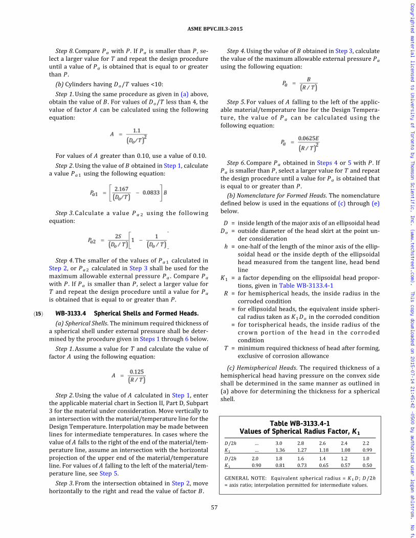
ð15Þ
Step 8. Compare Pa with P . If Pa is smaller than P , se-lect a larger value for T and repeat the design procedureuntil a value of Pa is obtained that is equal to or greaterthan P .
(b) Cylinders having Do/T values <10:
Step 1. Using the same procedure as given in (a) above,obtain the value of B . For values of Do/T less than 4, thevalue of factor A can be calculated using the followingequation:
For values of A greater than 0.10, use a value of 0.10.
Step 2. Using the value of B obtained in Step 1, calculatea value Pa1 using the following equation:
Step 3. Calculate a value P a 2 using the followingequation:
Step 4. The smaller of the values of Pa1 calculated inStep 2, or Pa2 calculated in Step 3 shall be used for themaximum allowable external pressure Pa . Compare Pa
with P . If Pa is smaller than P , select a larger value forT and repeat the design procedure until a value for Pa
is obtained that is equal to or greater than P .
WB-3133.4 Spherical Shells and Formed Heads.
(a) Spherical Shells. The minimum required thickness ofa spherical shell under external pressure shall be deter-mined by the procedure given in Steps 1 through 6 below.
Step 1. Assume a value for T and calculate the value offactor A using the following equation:
Step 2. Using the value of A calculated in Step 1, enterthe applicable material chart in Section II, Part D, Subpart3 for the material under consideration. Move vertically toan intersection with the material/temperature line for theDesign Temperature. Interpolation may be made betweenlines for intermediate temperatures. In cases where thevalue of A falls to the right of the end of the material/tem-perature line, assume an intersection with the horizontalprojection of the upper end of the material/temperatureline. For values of A falling to the left of the material/tem-perature line, see Step 5.
Step 3. From the intersection obtained in Step 2, movehorizontally to the right and read the value of factor B .
Step 4. Using the value of B obtained in Step 3, calculatethe value of the maximum allowable external pressure Pa
using the following equation:
Step 5. For values of A falling to the left of the applic-able material/temperature line for the Design Tempera-ture, the value of P a can be calculated using thefollowing equation:
Step 6. Compare Pa obtained in Steps 4 or 5 with P . IfPa is smaller than P , select a larger value for T and repeatthe design procedure until a value for Pa is obtained thatis equal to or greater than P .
(b) Nomenclature for Formed Heads. The nomenclaturedefined below is used in the equations of (c) through (e)below.
D = inside length of the major axis of an ellipsoidal headDo = outside diameter of the head skirt at the point un-
der considerationh = one‐half of the length of the minor axis of the ellip-
soidal head or the inside depth of the ellipsoidalhead measured from the tangent line, head bendline
K1 = a factor depending on the ellipsoidal head propor-tions, given in Table WB-3133.4-1
R = for hemispherical heads, the inside radius in thecorroded condition
= for ellipsoidal heads, the equivalent inside spheri-cal radius taken as K1Do in the corroded condition
= for torispherical heads, the inside radius of thecrown portion of the head in the corrodedcondition
T = minimum required thickness of head after forming,exclusive of corrosion allowance
(c) Hemispherical Heads. The required thickness of ahemispherical head having pressure on the convex sideshall be determined in the same manner as outlined in(a) above for determining the thickness for a sphericalshell.
Table WB-3133.4-1Values of Spherical Radius Factor, K 1
D/2h … 3.0 2.8 2.6 2.4 2.2K1 … 1.36 1.27 1.18 1.08 0.99
D/2h 2.0 1.8 1.6 1.4 1.2 1.0K1 0.90 0.81 0.73 0.65 0.57 0.50
GENERAL NOTE: Equivalent spherical radius = K 1D ; D/2h= axis ratio; interpolation permitted for intermediate values.
57
ASME BPVC.III.3-2015
Copyrighted material licensed to University of Toronto by Thomson Scientific, Inc. (www.techstreet.com). This copy downloaded on 2015-07-14 21:45:42 -0500 by authorized user logan ahlstrom. No further reproduction or distribution is permitted.

ð15Þ
ð15Þ
(d) Ellipsoidal Heads. The required thickness of an ellip-soidal head having pressure on the convex side, eitherseamless or of built‐up construction with butt joints, shallnot be less than that determined by the followingprocedure.Step 1. Assume a value for T and calculate the value of
factor A using the following equation:
Step 2. Using the value of A calculated in Step 1, followthe same procedure as that given for spherical shells in(a) Step 2 through (a) Step 6 above.(e) Torispherical Heads. The required thickness of a tor-
ispherical head having pressure on the convex side, eitherseamless or of built‐up construction with butt joints, shallnot be less than that determined by the same design pro-cedure as is used for ellipsoidal heads given in (d) above,using the appropriate value for R .
WB-3133.5 Stiffening Rings for Cylindrical Shells.(a) The required moment of inertia of the combined
ring‐shell section is given by the equation:
The available moment of inertia I for a stiffening ringshall be determined by the procedure given in Steps 1through 6 below.Step 1. Assuming that the shell has been designed and
Do , L s , and Tn are known, select a member to be usedfor the stiffening ring and determine its area As and thevalue of I defined in WB-3133.2. Then calculate B bythe equation:
Step 2. Enter the right‐hand side of the applicable mate-rial chart in Section II, Part D, Subpart 3 for the materialunder consideration at the value of B determined in Step1. If different materials are used for the shell and stiffen-ing ring, then use the material chart resulting in the largervalue for factor A in Step 4 or Step 5 below.Step 3. Move horizontally to the left to the material/
temperature line for the design metal temperature. Forvalues of B falling below the left end of the material/tem-perature line, see Step 5.Step 4. Move vertically to the bottom of the chart and
read the value of A .Step 5. For values of B falling below the left end of the
material/temperature line for the Design Temperature,the value of A can be calculated using the followingequation:
Step 6. If the required I s is greater than the computedmoment of inertia I for the combined ring‐shell sectionselected in Step 1, a new section with a larger momentof inertia must be selected and a new I s determined. Ifthe required I s is smaller than the computed I for the sec-tion selected in Step 1, that section should be satisfactory.(b) Stiffening rings may be attached to either the out-
side or the inside of the containment by continuouswelding.
WB-3133.6 Cylinders Under Axial Compression. Themaximum allowable compressive stress to be used in thedesign of cylindrical shells subjected to loadings that pro-duce longitudinal compressive stresses in the shell or wallshall be the lesser of the values given in (a) or (b) below:(a) the Sm value for the applicable material at Design
Temperature given in Section II, Part D, Subpart 1, Tables2A and 2B(b) the value of the factor B determined from the ap-
plicable chart in Section II, Part D, Subpart 3 using the fol-lowing definitions for the symbols on the charts:
R = inside radius of the cylindrical shellT = selected thickness of the shell, exclusive of the corro-
sion allowance
The value of B shall be determined from the applicablechart contained in Section II, Part D, Subpart 3 as given inSteps 1 through 5 below.Step 1. Using the selected values of T and R , calculate
the value of factor A using the following equation:
Step 2. Using the value of A calculated in Step 1, enterthe applicable material chart in Section II, Part D, Subpart3 for the material under consideration. Move vertically toan intersection with the material/temperature line for theDesign Temperature. Interpolation may be made betweenlines for intermediate temperatures. In cases where thevalue at A falls to the right of the end of the material/tem-perature line, assume an intersection with the horizontalprojection of the upper end of the material/temperatureline. For values of A falling to the left of the material/tem-perature line, see Step 4.Step 3. From the intersection obtained in Step 2, move
horizontally to the right and read the value of factor B .This is the maximum allowable compressive stress forthe values of T and R used in Step 1.Step 4. For values of A falling to the left of the applic-
able material/temperature line, the value of B shall becalculated using the following equation:
Step 5. Compare the value of B determined in Step 3 orStep 4 with the computed longitudinal compressive stressin the cylindrical shell, using the selected values of T and
58
ASME BPVC.III.3-2015
Copyrighted material licensed to University of Toronto by Thomson Scientific, Inc. (www.techstreet.com). This copy downloaded on 2015-07-14 21:45:42 -0500 by authorized user logan ahlstrom. No further reproduction or distribution is permitted.

ð15Þ
ð15Þ
R . If the value of B is smaller than the computed compres-sive stress, a greater value of T must be selected and thedesign procedure repeated until a value of B is obtainedwhich is greater than the compressive stress computedfor the loading on the cylindrical shell.
WB-3134 Leak Tightness
The leak tightness requirements for each containmentshall be set forth in the Design Specification.
WB-3135 Attachments
(a) Except as permitted in (c) and (d) below, attach-ments and connecting welds within the jurisdictionalboundary of the containment as defined in WB-1130 shallmeet the stress limits of the containment.
(b) The design of the containment shall include consid-eration of the interaction effects and loads transmittedthrough the attachment to and from the containment.Thermal stresses, stress concentrations, and restraint ofthe containment shall be considered.
(c) Beyond 2t from the outside surface of the contain-ment shell, where t is the nominal thickness of the con-tainment shell , the appropriate design rules asidentified in the Design Specification may be used.
(d) Nonstructural attachments shall meet the require-ments of WB-4435.
WB-3200 DESIGN OF CONTAINMENTS
WB-3210 DESIGN CRITERIAWB-3211 Requirements for Acceptability
The requirements for the acceptability of a design byanalysis are given in (a) through (d) below.
(a) The design shall be such that stress intensities willnot exceed the limits described in this subarticle and ta-bulated in Section II, Part D, Subpart 1, Tables 2A, 2B,and 4. The material shall not be used at metal or DesignTemperature that exceeds the temperature limit in theapplicability column for which stress intensity valuesare listed. The values in the tables may be interpolatedfor intermediate temperatures.
(b) The design details shall conform to the rules givenin this Article.
(c) For configurations where compressive stresses oc-cur, in addition to the requirements in (a) and (b) above,the critical buckling stress shall be taken into account asspecified in WB-3133.
(d) Protection against nonductile fracture shall be pro-vided. An acceptable procedure for nonductile failure pre-vention is given in WB-2300.
WB-3212 Basis for Determining Stresses
The theory of failure, used in the rules of this Subsec-tion for combining stresses, is the maximum shear stresstheory. The maximum shear stress at a point is equal to
one‐half the difference between the algebraically largestand the algebraically smallest of the three principal stres-ses at the point.
WB-3213 Terms Relating to Stress Analysis
Terms used in this Subsection relating to stress analy-sis are defined in the following subparagraphs.
WB-3213.1 Stress Intensity.16 Stress intensity is de-fined as twice the maximum shear stress, which is the dif-ference between the algebraically largest principal stressand the algebraically smallest principal stress at a givenpoint. Tensile stresses are considered positive and com-pressive stresses are considered negative.
WB-3213.2 Gross Structural Discontinuity. Grossstructural discontinuity is a geometric or material discon-tinuity that affects the stress or strain distributionthrough the entire wall thickness of the containment.Gross discontinuity‐type stresses are those portions ofthe actual stress distributions that produce net bendingand membrane force resultants when integrated throughthe wall thickness. Examples of a gross structural discon-tinuity are head‐to‐shell junctions, flange‐to‐shell junc-tions, reinforcement of openings in containment shellsand heads, and junctions between shells of different dia-meters or thicknesses.
WB-3213.3 Local Structural Discontinuity. Localstructural discontinuity is a geometric or material discon-tinuity that affects the stress or strain distributionthrough a fractional part of the wall thickness. The stressdistribution associated with a local discontinuity causesonly very localized deformation or strain and has no sig-nificant effect on the shell‐type discontinuity deforma-tions. Examples are small f i l let radii and smallattachments.
WB-3213.4 Normal Stress. Normal stress is the com-ponent of stress normal to the plane of reference. This isalso referred to as direct stress. Usually the distribution ofnormal stress is not uniform through the thickness of apart, so this stress is considered to have two components,one uniformly distributed and equal to the average stressacross the thickness under consideration, and the othervarying from this average value across the thickness.
WB-3213.5 Shear Stress. Shear stress is the compo-nent of stress tangent to the plane of reference.
WB-3213.6 Membrane Stress. Membrane stress isthe component of normal stress that is uniformly distrib-uted and equal to the average stress across the thicknessof the section under consideration.
WB-3213.7 Bending Stress. Bending stress is thecomponent of normal stress that varies across the thick-ness. The variation may or may not be linear.
WB-3213.8 Primary Stress. Primary stress is anynormal stress or shear stress developed by an imposedloading, that is necessary to satisfy the laws of
59
ASME BPVC.III.3-2015
Copyrighted material licensed to University of Toronto by Thomson Scientific, Inc. (www.techstreet.com). This copy downloaded on 2015-07-14 21:45:42 -0500 by authorized user logan ahlstrom. No further reproduction or distribution is permitted.

equilibrium of external and internal forces and moments.The basic characteristic of a primary stress is that it is notself‐limiting. Primary stresses that considerably exceedthe yield strength will result in failure or, at least, in grossdistortion. Primary membrane stress is divided into gen-eral and local categories. A general primary membranestress is one that is so distributed in the structure thatno redistribution of load occurs as a result of yielding. Ex-amples of primary stress are:(a) general membrane stress in a circular cylindrical
shell or a spherical shell due to internal pressure or to dis-tributed loads;(b) bending stress in the central portion of a flat head
due to pressure;(c) longitudinal stress due to cylinder bending in the
central portion of a horizontal cylindrical shell being de-celerated by forces applied at its extreme ends.Refer to Table WB-3217-1 for examples of primary
stress.
WB-3213.9 Secondary Stress. Secondary stress is anormal stress or a shear stress developed by the con-straint of adjacent material or by self‐constraint of thestructure. The basic characteristic of a secondary stressis that it is self‐limiting. Local yielding and minor distor-tions can satisfy the conditions that cause the stress to oc-cur and failure from one application of the stress is not tobe expected. Examples of secondary stress are:(a) general thermal stress [WB-3213.13(a)];(b) bending stress at a gross structural discontinuity.Refer to Table WB-3217-1 for examples of secondary
stress.
WB-3213.10 Local Primary Membrane Stress. Casesarise in which a membrane stress produced by pressureor other mechanical loading and associated with a discon-tinuity would, if not limited, produce excessive distortionin the transfer of load to other portions of the structure.Conservatism requires that such a stress be classified asa local primary membrane stress even though it has somecharacteristics of a secondary stress.A stressed region may be considered local if the dis-
tance over which the membrane stress intensity exceeds1.1Sm does not extend in the meridional direction morethan , where R is the minimum midsurface radiusof curvature and t is the minimum thickness in the regionconsidered. Regions of local primary stress intensity in-volving axisymmetric membrane stress distributions thatexceed 1.1Sm shall not be closer in the meridional direc-
tion than , where RL is defined as (R1 + R2)/2
and t L is defined as (t 1 + t 2 )/2 (where t 1 and t 2 arethe minimum thicknesses at each of the regions consid-ered, and R1 and R2 are the minimum midsurface radiiof curvature at these regions where the membrane stressintensity exceeds 1.1Sm ). Discrete regions of local pri-mary membrane stress intensity, such as those resultingfrom concentrated loads acting on brackets, where the
membrane stress intensity exceeds 1.1Sm , shall be spacedso that there is no overlapping of the areas in which themembrane stress intensity exceeds 1.1Sm .
WB-3213.11 Peak Stress. Peak stress is that incre-ment of stress that is additive to the primary plus second-ary stresses by reason of local discontinuities or localthermal stress [WB-3213.13(b)], or localized applicationof dynamic load including the effects, if any, of stress con-centrations. The basic characteristic of a peak stress isthat it does not cause any noticeable distortion and is ob-jectionable only as a possible source of a fatigue crack or abrittle fracture. A stress that is not highly localized fallsinto this category if it is of a type that cannot cause notice-able distortion. Examples of peak stress are:(a) the thermal stress in the austenitic steel cladding of
a carbon steel part;(b) certain thermal stresses that may cause fatigue but
not distortion;(c) the stress at a local structural discontinuity;(d) surface stresses produced by thermal shock.
WB-3213.12 Load Controlled Stress. Load controlledstress is the stress resulting from application of a loading,such as internal pressure, inertial loads, or gravity, whosemagnitude is not reduced as a result of displacement.
WB-3213.13 Thermal Stress. Thermal stress is a self‐balancing stress produced by a nonuniform distributionof temperature or by differing thermal coefficients of ex-pansion. Thermal stress is developed in a solid bodywhenever a volume of material is prevented from assum-ing the size and shape that it normally would under achange in temperature. For the purpose of establishing al-lowable stresses, two types of thermal stress are recog-nized, depending on the volume or area in whichdistortion takes place, as described in (a) and (b) below.(a) General thermal stress is associated with distortion
of the structure in which it occurs. If a stress of this type,neglecting stress concentrations, exceeds twice the yieldstrength of the material, the elastic analysis may be inva-lid and successive thermal cycles may produce incremen-tal distortion. Therefore this type is classified assecondary stress in Table WB-3217-1. Examples of gener-al thermal stress are:
(1) stress produced by an axial temperature distribu-tion in a cylindrical shell;
(2) stress produced by the temperature differencebetween a nozzle and the shell to which it is attached;
(3) the equivalent linear stress17 produced by the ra-dial temperature distribution in a cylindrical shell.(b) Local thermal stress is associated with almost com-
plete suppression of the differential expansion and thusproduces no significant distortion. Such stresses shall beconsidered only from the fatigue standpoint and arethere fore c lass i f ied as peak stresses in TableWB-3217-1. Examples of local thermal stress are:
(1) the stress in a small hot spot in a containmentwall;
60
ASME BPVC.III.3-2015
Copyrighted material licensed to University of Toronto by Thomson Scientific, Inc. (www.techstreet.com). This copy downloaded on 2015-07-14 21:45:42 -0500 by authorized user logan ahlstrom. No further reproduction or distribution is permitted.

ð15Þ
ð15Þ
ð15Þ
(2) the difference between the actual stress and theequivalent linear stress resulting from a radial tempera-ture distribution in a cylindrical shell;
(3) the thermal stress in a cladding material that hasa coefficient of expansion different from that of the basemetal.
WB-3213.14 Total Stress. Total stress is the sum ofthe primary, secondary, and peak stress contributions.Recognition of each of the individual contributions is es-sential to establishment of appropriate stress limitations.
WB-3213.15 Operational Cycle. Operational cycle isdefined as the initiation and establishment of new condi-tions followed by a return to the conditions that prevailedat the beginning of the cycle. The types of operating con-ditions that may occur are further defined in WB-3113.
WB-3213.16 Stress Cycle. Stress cycle is a conditionin which the alternating stress difference [WB-3222.9(e)]goes from an initial value through an algebraic maximumvalue to an algebraic minimum value and then returns tothe initial value. A single operational cycle may result inone or more stress cycles. Dynamic effects shall also beconsidered as stress cycles.
WB-3213.17 Fatigue Strength Reduction Factor. Fa-tigue strength reduction factor is a stress intensificationfactor that accounts for the effect of a local structural dis-continuity (stress concentration) on the fatigue strength.In the absence of experimental data, the theoretical stressconcentration factor may be used.
WB-3213.18
DELETED
WB-3213.19
DELETED
WB-3213.20 Deformation. Deformation of a compo-nent part is an alteration of its shape or size.
WB-3213.21 Ratcheting. Ratcheting is a progressiveincremental inelastic deformation or strain that can occurin a component that is subjected to variations of mechan-ical stress, thermal stress, or both.
WB-3213.22 Shakedown. Shakedown of a structureoccurs if, after a few cycles of load application, ratchetingceases. The subsequent structural response is elastic, orelastic–plastic, and progressive incremental inelastic de-formation is absent. Elastic shakedown is the case inwhich the subsequent response is elastic.
WB-3214 Stress Analysis
A detailed stress analysis of all major structural compo-nents shall be prepared in sufficient detail to show thateach of the stress limitations of WB-3220 and WB-3230is satisfied when the component is subjected to the load-ings of WB-3110.
WB-3215 Derivation of Stress Intensities
One requirement for the acceptability of a design(WB-3210) is that the calculated stress intensities shallnot exceed specified allowable limits. These limits differdepending on the stress category (primary, secondary,etc.) from which the stress intensity is derived. This para-graph describes the procedure for the calculation of thestress intensities that are subject to the specified limits.The steps in the procedure are stipulated in (a) through(e) below.
(a) At the point on the component that is being investi-gated, choose an orthogonal set of coordinates, such astangential, longitudinal, and radial, and designate themby the subscripts t , l , and r . The stress components inthese directions are then designated σ t , σ l , and σ r for di-rect stresses and τ l t , τ l r , and τ r t for shear stresses.
(b) Calculate the stress components for each type ofloading to which the part will be subjected, and assigneach set of stress values to one or a group of the followingcategories:
(1) gene r a l p r ima ry membrane s t r e s s P m
(WB-3213.8);(2) l o c a l p r i m a r y m em b r a n e s t r e s s P L
(WB-3213.10);(3) primary bending stress P b (WB-3213.7 and
WB-3213.8);(4) secondary stress Q (WB-3213.9);(5) peak stress F (WB-3213.11).
WB-3217 provides guidance for this step.(c) For each category, calculate the algebraic sum of the
σ t values that result from the different types of loadingsand similarly for the other five stress components. Certaincombinations of the categories must also be considered.
(d) Translate the stress components for the t , l , and rdirections into principal stresses σ1 , σ2 , and σ3 . In manypressure component calculations, the t , l , and r directionsmay be so chosen that the shear stress components arezero and σ1 , σ2 , and σ3 are identical to σ t , σ l , and σ r .
(e) Calculate the stress differences S12 , S23 , and S31
from the relations:
The stress intensity18 S is the largest absolute value ofS12 , S23 , and S31 .
61
ASME BPVC.III.3-2015
Copyrighted material licensed to University of Toronto by Thomson Scientific, Inc. (www.techstreet.com). This copy downloaded on 2015-07-14 21:45:42 -0500 by authorized user logan ahlstrom. No further reproduction or distribution is permitted.

ð15Þ
ð15Þ
WB-3216 Derivation of Stress Differences
If the specified operation of the component does notmeet the conditions of WB-3222.9(d), the ability of thecomponent to withstand the specified cyclic operationwithout fatigue failure shall be determined as providedin WB-3222.9(e). The determination shall be made onthe basis of the stresses at a point of the component,and the allowable stress cycles shall be adequate for thespecified service at every point. Only the stress differ-ences due to cyclic operating loadings, as specified inthe Design Specification, need to be considered.
WB-3216.1 Constant Principal Stress Direction. Forany case in which the directions of the principal stressesat the point being considered do not change during the cy-cle, the steps stipulated in (a) through (c) below shall betaken to determine the alternating stress intensity.(a) Principal Stresses. Consider the values of the three
principal stresses at the point versus time for the com-plete stress cycle, taking into account both the grossand local structural discontinuities and the thermal ef-fects, which vary during the cycle. These are designatedas σ1 , σ2 , and σ3 for later identification.(b) Stress Differences. Determine the stress differences
S12 = σ1 − σ2 , S23 = σ2 − σ3 , and S31 = σ3 − σ1 versustime for the complete cycle. In what follows, the symbolS i j is used to represent any one of these three stressdifferences.(c) Alternating Stress Intensity. Determine the extremes
of the range through which each stress difference Si j fluc-tuates and find the absolute magnitude of this range foreach Si j . Call this magnitude Sr i j and let Sa l t i j = 0.5Sr i j .The alternating stress intensity Sa l t is the largest Sa l t i j
value.
WB-3216.2 Varying Principal Stress Direction. Forany case in which the directions of the principal stressesat the point being considered do change during the stresscycle, it is necessary to use the more general procedure of(a) through (e) below.(a) Consider the values of the six stress components σ t ,
σ l , σ r , τ l t , τ l r , and τ r t versus time for the complete stresscycle, taking into account both the gross and local struc-tural discontinuities and the thermal effects that vary dur-ing the cycle.(b) Choose a point in time when the conditions are one
of the extremes for the cycle (either maximum or mini-mum, algebraically) and identify the stress componentsat this time by the subscript i . In most cases, it will be pos-sible to choose at least one time during the cycle when theconditions are known to be extreme. In some cases, it maybe necessary to try different points in time to find the onethat results in the largest value of alternating stressintensity.(c) Subtract each of the six stress components σ t i , σ l i ,
etc., from the corresponding stress components σ t , σ l ,etc., at each point in time during the cycle and call the re-sulting components σ ′ t , σ ′ l , etc.
(d) At each point in time during the cycle, calculate theprincipal stresses σ ′1 , σ ′2 , and σ ′3 derived from the sixstress components σ ′ t , σ ′ l , etc. Note that the directionsof the principal stresses may change during the cyclebut each principal stress retains its identity as it rotates.(e) Determine the stress differences S ′12 = σ ′1 − σ ′2 ,
S ′23 = σ ′2 − σ ′3 , and S ′31 = σ ′3 − σ ′1 versus time forthe complete cycle and find the largest absolute magni-tude of any stress difference at any time. The alternatingstress intensity Sa l t is one‐half of this magnitude.
WB-3217 Classification of Stresses
Table WB-3217-1 provides assistance in the determi-nation of the category to which a stress should beassigned.
WB-3220 STRESS LIMITS FOR OTHER THANBOLTS
WB-3221 Design Limits
The stress intensity limits that must be satisfied for De-sign Loadings (WB-3112) stated in the Design Specifica-tion are the limits of the following subparagraphs andthe Special Stress Limits of WB-3227. The design stressintensity values Sm are given by WB-3229. The limitsare summarized in Figure WB-3221-1.
WB-3221.1 General Primary Membrane Stress In-tensity. (Derived from Pm in Figure WB-3221-1) Thisstress intensity is derived from the average value acrossthe thickness of a section of the general primary stresses(WB-3213.8) produced by Design Loadings, which in-clude internal pressure and other specified mechanicalloads, but excluding secondary and peak stresses. Aver-aging is to be applied to the stress components prior todetermination of the stress intensity values. The allow-able value of this stress intensity is Sm at the DesignTemperature.
WB-3221.2 Local Primary Membrane Stress Inten-sity. (Derived from PL in Figure WB-3221-1) This stressintensity is derived from the average value across thethickness of a section of the local primary stresses(WB-3213.10) produced by Design Pressure and specifiedDesign Mechanical Loads, but excluding all thermal andpeak stresses. Averaging is to be applied to the stresscomponents prior to the determination of the stress in-tensity values. The allowable value of the stress intensityis 1.5Sm .
WB-3221.4 Primary Membrane (General or Local)Plus Primary Bending Stress Intensity. [Derived from(Pm or PL) + Pb in Figure WB-3221-1] This stress inten-sity is derived from the highest value across the thicknessof a section of the general or local primary membranestresses plus primary bending stresses produced by De-sign Pressure and other specified Design MechanicalLoads, but excluding all secondary and peak stresses.For solid rectangular sections, the allowable value of this
62
ASME BPVC.III.3-2015
Copyrighted material licensed to University of Toronto by Thomson Scientific, Inc. (www.techstreet.com). This copy downloaded on 2015-07-14 21:45:42 -0500 by authorized user logan ahlstrom. No further reproduction or distribution is permitted.

ð15ÞTable WB-3217-1Classification of Stress Intensity in Containments for Some Typical Cases
Containment Part Location Origin of Stress Type of Stress Classification
Cylindrical or spherical shell Shell plate remotefrom discontinuities
Internal pressure General membrane Pm
Gradient through platethickness
Q
Axial thermal gradient Membrane Q
Bending Q
Junction with head orflange
Internal pressure Membrane PL
Bending Q [Note (1)]
Any shell or head Any section acrossentire containment
External load ormoment, or internalpressure
General membraneaveraged across fullsection
Pm
External load or moment Bending across fullsection
Pm
Near nozzle or otheropening
External load ormoment, or internalpressure
Local membrane PL
Bending Q
Peak (fillet or corner) F
Any location Temperature differencebetween shell andhead
Membrane Q [Note (2)]
Bending Q [Note (3)]
Any location awayfrom impact area
Impact on unyieldingsurface
General membrane Pm
Bending across fullsection
Pm
At impact area Impact on puncture bar Local membrane PL [Note (4)]
Local bending Q
Dished head or conical head Crown Internal pressure Membrane Pm
Bending Pb
Knuckle or junction toshell
Internal pressure Membrane PL [Note (5)]
Bending Q
Flat head Center region Internal pressure Membrane Pm
Bending Pb
Junction to shell Internal pressure Membrane PL
Bending Q [Note (1)]
Square or rectangularcontainment of flat plates
Center region Uniform pressure Membrane Pm
Bending Pb
Junction between flatplates
Uniform pressure Membrane PL
Bending Pb
Any section acrossentire containment
Lateral internal loading Bending across fullcross section
Pm
Cladding Any Differential expansion Membrane F
Bending F
Any Any Radial temperaturedistribution [Note (6)]
Equivalent linearstress [Note (7)]
Q
Nonlinear portion ofstress distribution
F
Any Any Any Stress concentration(notch effect)
F
GENERAL NOTE: Q and F classification of stresses refers to other than design condition (Figure WB-3222-1).
NOTES:(1) If the bending moment at the edge is required to maintain the bending stress in the middle to acceptable limits, the edge bending is
classified as Pb . Otherwise, it is classified as Q .
63
ASME BPVC.III.3-2015
Copyrighted material licensed to University of Toronto by Thomson Scientific, Inc. (www.techstreet.com). This copy downloaded on 2015-07-14 21:45:42 -0500 by authorized user logan ahlstrom. No further reproduction or distribution is permitted.
ð15Þ
ð15Þ
ð15Þ
stress intensity is 1.5Sm . For other than solid rectangularsections, a value of α times the limit established inWB-3221.1 may be used, where the factor α is definedas the ratio of the load set producing a fully plastic sectionto the load set producing initial yielding in the extreme fi-bers of the section. In the evaluation of the initial yieldand fully plastic section capacities, the ratios of each indi-vidual load in the respective load set to each other load inthat load set shall be the same as the respective ratios ofthe individual loads in the specified design load set. Thevalue of α shall not exceed the value calculated for bend-ing only (Pm = 0). In no case shall the value of α exceed1.5. The propensity for buckling of the part of the sectionthat is in compression shall be investigated.
WB-3222 Level A Services Limits
The stress intensity limits that must be satisfied fornormal loadings (WB-3113) stated in the Design Specifi-cation are the Level A Service Limits [WA-2123.4(b)(1)]of the following subparagraphs and the Special StressLimits of WB-3227. The design stress intensity valuesSm are given by WB-3229. The limits are summarizedin Figure WB-3222-1.
WB-3222.1 General Primary Membrane Stress In-tensity. (Derived from Pm in Figure WB-3222-1) Thisstress intensity is derived from the average value acrossthe thickness of a section of the general primary stresses(WB-3213.8) produced by normal loads, which include in-ternal pressure and other specified mechanical loads, butexcluding secondary and peak stresses. Averaging is to beapplied to the stress components prior to determinationof the stress intensity values. The allowable value of thisstress intensi ty is S m at the normal operat ingtemperature.
WB-3222.2 Local Primary Membrane Stress Inten-sity. (Derived from PL in Figure WB-3222-1) This stressintensity is derived from the average value across thethickness of a section of the local primary stresses(WB-3213.10) produced by normal loads, but excluding
all thermal and peak stresses. Averaging is to be appliedto the stress components prior to the determination ofthe stress intensity values. The allowable value of thisstress intensity is 1.5Sm .
WB-3222.4 Primary Membrane (General or Local)Plus Primary Bending Stress Intensity. [Derived from(Pm or PL) + Pb in Figure WB-3222-1] This stress inten-sity is derived from the highest value across the thicknessof a section of the general or local primary membranestresses plus primary bending stresses produced by De-sign Pressure and other specified Design MechanicalLoads, but excluding all secondary and peak stresses.For solid rectangular sections, the allowable value of thisstress intensity is 1.5Sm . For other than solid rectangularsections, a value of α times the limit established inWB-3222.1 may be used, where the factor α is definedas the ratio of the load set producing a fully plastic sectionto the load set producing initial yielding in the extreme fi-bers of the section. In the evaluation of the initial yieldand fully plastic section capacities, the ratios of each indi-vidual load in the respective load set to each other load inthat load set shall be the same as the respective ratios ofthe individual loads in the specified design load set. Thevalue of α shall not exceed the value calculated for bend-ing only (Pm = 0). In no case shall the value of α exceed1.5. The propensity for buckling of the part of the sectionthat is in compression shall be investigated.
WB-3222.6 Primary Plus Secondary StressIntensity.19 [Derived from (Pm or PL) + Pb + Q in FigureWB-3222-1]. This stress intensity is derived from thehighest value at any point across the thickness of a sectionof the general or local primary membrane stresses, plusprimary bending stresses plus secondary stresses, pro-duced by normal loads. The allowable value of the maxi-mum range of this stress intensity is 3Sm .
WB-3222.7
DELETED
Table WB-3217-1Classification of Stress Intensity in Containments for Some Typical Cases (Cont'd)
NOTES (CONT'D):(2) Components such as concentric shells attached to each other at the ends or in close radial contact may develop stresses due to tem-
perature differences or differential expansion between dissimilar materials. Members subjected to compressive load shall be eval-uated against buckling, treating the membrane stresses as Pm.
(3) If an end connection of two concentric shells is relatively weak, the differential thermal expansion of the shells may lead to the for-mation of a plastic hinge in the connection and could cause excessive deformation or failure. The end connection shall be evaluatedfor such a condition treating the bending stresses as Pb .
(4) The special stress limits of WB-3227 shall also be met.(5) Consideration shall also be given to the possibility of wrinkling and excessive deformation in containments with a large
diameter–thickness ratio.(6) Consider possibility of thermal stress ratchet.(7) Equivalent linear stress is defined as the linear stress distribution that has the same net bending moment as the actual stress
distribution.
64
ASME BPVC.III.3-2015
Copyrighted material licensed to University of Toronto by Thomson Scientific, Inc. (www.techstreet.com). This copy downloaded on 2015-07-14 21:45:42 -0500 by authorized user logan ahlstrom. No further reproduction or distribution is permitted.

ð15ÞFigure WB-3221-1Stress Categories and Limits of Stress Intensity for Design Loadings
Description (for examples see Table WB-3217-1)
General Membrane Stress
Category
Symbol [Note (1)]
Local Membrane Bending
Average primary stress across solid section. Excludes discontinuities and concentra-tions. Produced by Design Loads.
Combination of stress compo-nents and allowable limits of stress intensities.
Average stressacross any solid section. Considers discontinuities but not concen-trations. Produced by Design Loads.
Component of primary stress proportional to distance from centroid of solid section. Excludes discontinuities and concentra-tions. Produced by Design Loads.
Pm
Pm Sm
PL
PL
(Pm or PL ) + Pb
1.5Sm
1.5Sm
Pb
Primary
[Note (2)]
Legend:
= Allowable value
= Calculated value
NOTES:(1) The symbols Pm , PL , and Pb do not represent single quantities, but rather sets of six quantities representing the six stress components σ t ,
σ l , σ r , τ l t , τ l r , and τ r t .(2) Allowable values shown are for a solid rectangular section. See WB-3221.4 for other than a solid rectangular section.
65
ASME BPVC.III.3-2015
Copyrighted material licensed to University of Toronto by Thomson Scientific, Inc. (www.techstreet.com). This copy downloaded on 2015-07-14 21:45:42 -0500 by authorized user logan ahlstrom. No further reproduction or distribution is permitted.

ð15Þ Figure WB-3222-1Stress Categories and Limits of Stress Intensity for Normal Loadings
Primary Secondary [Note (2)]
Stress Membrane PlusBendingCategory General Membrane Local Membrane Bending Peak
Description (for examples, Average primary stress Average stress across any Component of primary Increment added tosee Table WB-3217-1) across solid section. solid section. Considers stress proportional to
distance from centroid of solid section. Ex- cluding effects of discontinuities and concentrations. Pro- duced by pressure and mechanical loads, including inertia effects.
primary or second-Excludes disconti- discontinuities but ary stress by anuities and concentra- not concentrations. concentration
(notch).tions. Produced by Produced by pressure
Certain thermalpressure and mechani- and mechanical loads,
stresses that maycal loads. including inertia effects.
cause fatigue butnot distortion.
In local impactregions.
Symbol Pm PL Pb[Note (1)]
Combination of stress com-ponents and allowablelimits of stress intensities
Pm 1.0Sm PL 1.5Sm 1.5Sm
3Sm
[Note (5)][Note (4)]
Sa
Q F
[Notes (2) and (3)]
Self-equilibrating stress necessary to satisfy continuity of structure discontinuities. Can be caused by pressure, mechanical loads, or differential thermal expansion. Excludes local stress concentrations.
(Pm or PL) + Pb
[Note (6)]
(Pm or PL) + Pb + Q
(Pm or PL) + Pb + Q + F
Legend: = Allowable value
= Calculated value
NOTES:(1) The symbols Pm , PL , Pb , Q , and F do not represent single quantities, but sets of six quantities representing the six stress components: σ t , σ l , σ r , τ l t , τ l r , τ r t .(2) When the secondary stress is due to a temperature transient at the point at which the stresses are being analyzed, the value of Sm shall be taken as the average of the tabulated Sm values for
the highest and the lowest temperatures of the metal during the transient. When part or all of the secondary stress is due to the mechanical load, the value of Sm shall not exceed the valuefor the highest temperature during the transient.
(3) The 3Sm limit is applicable to the range of stresses.(4) The stresses in Category Q are those parts of the total stress that are produced by thermal gradients, structural discontinuities, etc., and they do not include primary stresses that may also
exist at the same point. However, it should be noted that a detailed stress analysis frequently gives the combination of primary and secondary stresses directly and, when appropriate, thecalculated value represents the total of Pm + Pb + Q , and not Q alone. Similarly, if the stress in Category F is produced by a stress concentration, the quantity F is the additional stressproduced by the notch over and above the nominal stress. For example, if a point has a nominal stress intensity Pm + Pm(K − 1) = KPm . However, PL is the total membrane stress thatresults from mechanical loads, including discontinuity effects rather than a stress increment. Therefore, the PL value always includes the Pm contribution.
(5) Sa is obtained from the fatigue curves, Section III Appendices, Mandatory Appendix I. The allowable stress intensity for the full range of fluctuation is 2Sa .(6) Allowable values shown are for a solid rectangular section. See WB-3222.4 for other than a solid rectangular section.
66
ASM
EBPVC.III.3
-2015
Copyrighted material licensed to University of Toronto by Thomson Scientific, Inc. (www.techstreet.com). This copy downloaded on 2015-07-14 21:45:42 -0500 by authorized user logan ahlstrom. No further reproduction or distribution is permitted.

ð15Þ WB-3222.9 Analysis for Cyclic Operation.(a) Suitability for Cyclic Operation. The suitability of a
component for specified normal loadings and Test Load-ings [if required by WB-3225(d)] involving cyclic applica-tion of loads and thermal conditions shall be determinedby the methods described herein, except that the suitabil-ity of high strength bolts shall be determined by the meth-ods of WB-3232.4(b), and the possibility of thermal stressratchet shall be investigated in accordance withWB-3222.11. If the specified normal loads of the compo-nent meet all of the conditions of (d) below, no analysisfor cyclic operation is required, and it may be assumedthat the limits on peak stress intensities, as governed byfatigue, have been satisfied by compliance with the applic-able requirements for material, design, fabrication, exam-ination, and testing of this Subsection. If the normal loadsdo not meet all the conditions of (d) below, a fatigue ana-lysis shall be made in accordance with (e) below or a fa-tigue test shall be made in accordance with Section IIIAppendices, Mandatory Appendix II, II-1500.
(b) Peak Stress Intensity. This stress intensity is derivedfrom the highest value at any point across the thickness ofa section of the combination of all primary, secondary,and peak stresses produced by specified normal loads.
(c) Conditions and Procedures. The conditions and pro-cedures of WB-3222.9 are based on a comparison of peakstresses with strain cycling fatigue data. The strain cyclingfatigue data are represented by design fatigue strengthcurves of Section III Appendices, Mandatory Appendix I.These curves show the allowable amplitude Sa of the al-ternating stress intensity component (one‐half of the al-ternating stress intensity range) plotted against thenumber of cycles. This stress intensity amplitude is calcu-lated on the assumption of elastic behavior and, hence,has the dimensions of stress, but does not represent a realstress when the elastic range is exceeded. The fatiguecurves are obtained from uniaxial strain cycling data inwhich the imposed strains have been multiplied by theelastic modulus and a design margin has been providedso as to make the calculated stress intensity amplitudeand the allowable stress intensity amplitude directly com-parable. Where necessary, the curves have been adjustedto include the maximum effects of mean stress, which isthe condition where the stress fluctuates about a meanvalue that is different from zero. As a consequence of thisprocedure, it is essential that the requirements ofWB-3222.6 be satisfied at all times with transient stressesincluded, and that the calculated value of the alternatingstress intensity be proportional to the actual strain ampli-tude. To evaluate the effect of alternating stresses of vary-ing amplitudes, a linear damage relation is assumed in(e)(5) below.
(d) Components Not Requiring Analysis for Cyclic Opera-tion. An analysis for cyclic operation is not required, and itmay be assumed that the limits on peak stress intensities,as governed by fatigue, have been satisfied for a compo-nent by compliance with the applicable requirements
for material, design, fabrication, examination, and testingof this Subsection, provided the specified normal loads ofthe component, or portion thereof, meet all the conditionsstipulated in (1) through (5) below.
(1) Atmospheric to Normal Pressure Cycle. The speci-fied number of times that the pressure will be cycled fromatmospheric pressure to normal pressure and back to at-mospheric pressure during normal conditions does notexceed the number of cycles on the applicable fatiguecurve of Section III Appendices, Mandatory Appendix I,corresponding to an Sa value of three times the Sm valuefor the material at the maximum normal temperature.
(2) Normal Pressure Fluctuation. The specified fullrange of pressure fluctuations during normal conditionsdoes not exceed the quantity 1/3 × Design Pressure ×(Sa/Sm), where Sa is the value obtained from the applic-able design fatigue curve for the total specified number ofsignificant pressure fluctuations and Sm is the allowablestress intensity for the material at the maximum normaltemperature. If the total specified number of significantpressure fluctuations exceeds the maximum number ofcycles defined on the applicable design fatigue curve,the Sa value corresponding to the maximum number ofcycles defined on the curve may be used. Significant pres-sure fluctuations are those for which the total excursionexceeds one-third of the Design Pressure multiplied by(Sa/Sm) where S is defined as follows:
(-a) If the total specified number of cycles is 106
cycles or less, S is the value of Sa obtained from the ap-plicable design fatigue curve for 106 cycles.
(-b) If the total specified number of cycles exceeds106 cycles, S is the value of Sa obtained from the applic-able design fatigue curve for the maximum number of cy-cles defined on the curve.
(3) Temperature Difference — Normal Condition. Thetemperature difference, °F (°C), between any two adja-cent points20 does not change21 during normal conditionsby more than the quantity Sa/2Eα , where Sa is the valueobtained from the applicable design fatigue curve of Sec-tion III Appendices, Mandatory Appendix I, for the totalspecified number of significant temperature differencefluctuations, α is the value of the instantaneous coefficientof thermal expansion, and E at the mean value of the tem-peratures at the two points as given by Section II, Part D,Subpart 2, Tables TE and TM. A temperature differencefluctuation shall be considered to be significant if its totalalgebraic range exceeds the quantity S/2Eα , where S isdefined as follows:
(-a) If the total specified number of cycles is 106
cycles or less, S is the value of Sa obtained from the ap-plicable design fatigue curve for 106 cycles.
(-b) If the total specified number of cycles exceeds106 cycles, S is the value of Sa obtained from the applic-able design fatigue curve for the maximum number of cy-cles defined on the curve.
67
ASME BPVC.III.3-2015
Copyrighted material licensed to University of Toronto by Thomson Scientific, Inc. (www.techstreet.com). This copy downloaded on 2015-07-14 21:45:42 -0500 by authorized user logan ahlstrom. No further reproduction or distribution is permitted.
(4) Temperature Difference — Dissimilar Materials.For components fabricated from materials of differingmoduli of elasticity or coefficients of thermal expansion,the total algebraic range of temperature fluctuation, °F(°C), experienced by the component during normal condi-tions does not exceed the magnitude Sa/2(E1α1 − E2α2),where Sa is the value obtained from the applicable designfatigue curve for the total specified number of significanttemperature fluctuations, E1 and E2 are the moduli ofelasticity (Section II, Part D, Subpart 2, Tables TM), andα1 and α2 are the values of the instantaneous coefficientsof thermal expansion (Section II, Part D, Subpart 2, TablesTE) at the mean temperature value involved for the twomaterials of construction. A temperature fluctuation shallbe considered to be significant if its total excursion ex-ceeds the quantity S/2(E1α1 − E2α2), where S is definedas follows:
(-a) If the total specified number of cycles is 106
cycles or less, S is the value of Sa obtained from the ap-plicable design fatigue curve for 106 cycles.
(-b) If the total specified number of cycles exceeds106 cycles, S is the value of Sa obtained from the applic-able design fatigue curve for the maximum number of cy-cles defined on the curve. If the two materials used havedifferent applicable design fatigue curves, the lower valueof Sa shall be used in applying the rules of this paragraph.
(5) Mechanical Loads. The specified full range of me-chanical loads, excluding pressure but including supportreactions, handling and transportation loads, and assem-bly/dissembly loads, does not result in load stresseswhose range exceeds the Sa value obtained from the ap-plicable design fatigue curve of Section III Appendices,Mandatory Appendix I, for the total specified number ofsignificant load fluctuations. If the total specified numberof significant load fluctuations exceeds the maximumnumber of cycles defined on the applicable design fatiguecurve, the Sa value corresponding to the maximum num-ber of cycles defined on the curve may be used. A loadfluctuation shall be considered to be significant if the totalexcursion of load stress exceeds the quantity S , where S isdefined as follows:
(-a) If the total specified number of cycles is 106
cycles or less, S is the value of Sa obtained from the ap-plicable design fatigue curve for 106 cycles.
(-b) If the total specified number of cycles exceeds106 cycles, S is the value of Sa obtained from the applic-able design fatigue curve for the maximum number of cy-cles defined on the curve.(e) Procedure for Analysis for Cyclic Loading. If the spe-
cified normal loads for the component do not meet theconditions of (d), the ability of the component to with-stand the specified cyclic operation without fatigue failureshall be determined as provided in this subsubparagraph.The determination shall be made on the basis of the stres-ses at a point, and the allowable stress cycles shall be ade-quate for the specified normal loads at every point. Onlythe stress differences due to operation cycles as specified
in the Design Specifications need be considered. Compli-ance with these requirements means only that the compo-nent is suitable from the standpoint of possible fatiguefailure; complete suitability for the specified normal loadsis also dependent on meeting the general stress limits ofWB-3222 and any applicable special stress limits ofWB-3227.
(1) Stress Differences. For each normal load, deter-mine the stress differences and the alternating stress in-tensity Sa in accordance with WB-3216.
(2) Local Structural Discontinuities. These effectsshall be evaluated for all conditions using stress concen-tration factors determined from theoretical, experimen-tal, or photoelastic studies, or numerical stress analysistechniques. Experimentally determined fatigue strengthreduction factors may be used when determined in accor-dance with the procedures of Section III Appendices, Man-datory Appendix II, II-1600, except for high strength alloysteel bolting for which the requirements of WB-3232.4(c)shall apply when using the design fatigue curve of SectionIII Appendices, Mandatory Appendix I, Figure I-9.4. No fa-tigue strength reduction factor greater than five need beused.
(3) Design Fatigue Curves. Section III Appendices,Mandatory Appendix I, contains the applicable fatigue de-sign curves for the materials permitted by this Subsec-tion. When more than one curve is presented for agiven material, the applicability of each is identified.Where curves for various strength levels of a materialare given, linear interpolation may be used for intermedi-ate strength levels of these materials. The strength level isthe specified minimum room temperature value.
(4) Effect of Elastic Modulus. Multiply Sa l t (as deter-mined in WB-3216.1 or WB-3216.2) by the ratio of themodulus of elasticity given on the design fatigue curveto the value of the modulus of elasticity used in the ana-lysis. Enter the applicable design fatigue curve of SectionIII Appendices, Mandatory Appendix I at this value on theordinate axis and find the corresponding number of cy-cles on the abscissa. If the operating cycle being consid-ered is the only one which produces significantfluctuating stresses, this is the allowable number ofcycles.
(5) Cumulative Damage. If there are two or moretypes of stress cycle that produce significant stresses,their cumulative effect shall be evaluated as stipulatedin Steps 1 through 6 below.Step 1. Designate the specified number of times each
type of stress cycle of types 1, 2, 3, ..., n , will be repeatedduring the life of the component as n 1 , n 2 , n 3 , ..., nn ,respectively.
NOTE: In determining n1 , n2 , n3 ,..., nn , consideration shall be givento the superposition of cycles of various origins that produce a totalstress difference range greater than the stress difference ranges ofthe individual cycles. For example, if one type of stress cycle pro-duces 1,000 cycles of a stress difference variation from zero to+60,000 psi (+414 MPa) and another type of stress cycle produces
68
ASME BPVC.III.3-2015
Copyrighted material licensed to University of Toronto by Thomson Scientific, Inc. (www.techstreet.com). This copy downloaded on 2015-07-14 21:45:42 -0500 by authorized user logan ahlstrom. No further reproduction or distribution is permitted.
ð15Þ
10,000 cycles of a stress difference variation from zero to−50,000 psi (−345 MPa), the two types of cycle to be consideredare defined by the following parameters:
(a) for type 1 cycle, n1 = 1,000 and Salt 1 = (60,000 + 50,000)/2 = 55,000 psi;
(b) for type 2 cycle, n 2 = 9,000 and Salt 2 = (50,000 + 0)/2 = 25,000 psi.
Step 2. For each type of stress cycle, determine the al-ternating stress intensity S a l t by the procedures ofWB-3216.1 or WB-3216.2 above. Call these quantitiesSa l t 1 , Sa l t 2 , Sa l t 3 , ..., Sa l t n .
Step 3. For each value Sa l t 1 , Sa l t 2 , Sa l t 3 , . . ., Sa l t n , usethe applicable design fatigue curve to determine the max-imum number of repetitions that would be allowable ifthis type of cycle were the only one acting. Call these val-ues N1 , N2 , N3 , ..., Nn.
Step 4. For each type of stress cycle, calculate the usagefactors U1 , U2 , U3 , ..., Un , from U1 = n1/N1 , U2 = n2/N2 ,U3 = n3/N3 , ..., Un = nn/Nn.
Step 5. Calculate the cumulative usage factor U fromU = U1 + U2 + U3 + ... + Un .
Step 6. The cumulative usage factor U shall not exceed1.0.
WB-3222.10 Deformation Limits. Any deformationlimits prescribed by the Design Specifications, such asthose intended to limit leakage, shall be satisfied.
WB-3222.11 Thermal Stress Ratchet. It should benoted that under certain combinations of steady stateand cyclic loadings there is a possibility of large distor-tions developing as the result of ratchet action; that is,the deformation increases by a nearly equal amount foreach cycle. Examples of this phenomenon are treated inthis subparagraph and in WB-3227.3.
(a) The limiting value of the maximum cyclic thermalstress permitted in a portion of an axisymmetric shellloaded by steady state internal pressure in order to pre-vent cyclic growth in diameter is as follows. Let
x = maximum general membrane stress due to pressuredivided by the yield strength,22 Sy
y ′ = maximum allowable range of thermal stress com-puted on an elastic basis divided by the yieldstrength,22 Sy
Case 1 : Linear variation of temperature through thewal l : for 0 < x < 0.5 , y ′ = 1/x and , for0.5 < x < 1.0, y ′ = 4(1 − x)
Case 2 : Parabolic constantly increasing or constantly de-creasing variation of temperature through thewall: for 0.615 < x < 1.0, y ′ = 5.2(1 − x) and, ap-proximately for x < 0.615, y ′ = 4.65, 3.55, and2.70 for x = 0.3, 0.4, and 0.5, respectively
(b) Use of yield strength, Sy , in the above relations in-stead of the proportional limit allows a small amount ofgrowth during each cycle until strain hardening raisesthe proportional limit to Sy . If the yield strength of thematerial is higher than 2 times the Sa value for the max-imum number of cycles on the applicable fatigue curve of
Section III Appendices, Mandatory Appendix I for the ma-terial, the latter value shall be used if there is to be a largenumber of cycles because strain softening may occur.
WB-3224 Level D Service Limits
(a) Level D Service Limits [WA-2123.4(b)(3)] are thoselimits that must be satisfied for accident loadings(WB-3113) stated in the Design Specification.
(b) Any deformation limits prescribed by the DesignSpecification for accident loadings, such as those to limitleakage, shall be satisfied.
WB-3224.1 Elastic Analysis. The stress intensity lim-its that must be satisfied for accident loadings stated inthe Design Specification are the Level D Service Limitsof this paragraph and in Figure WB-3224.1-1 for elasticanalysis. The design stress intensity values Sm are givenby WB-3229.
(a) The general primary membrane stress intensity Pm
shall not exceed the lesser of 2.4Sm and 0.7Su for auste-nitic steel, high‐nickel alloy, and copper–nickel alloy ma-terials included in Section II, Part D, Subpart 1, Tables2A and 2B, or 0.7Su for ferritic steel materials includedin Section II, Part D, Subpart 1, Table 2A.
(b) The local primary membrane stress intensity PL
shall not exceed 150% of the limit for general primarymembrane stress intensity Pm but not greater than 1.0Su .
(c) The primary membrane (general or local) plus pri-mary bending stress intensity, (Pm or PL) + Pb shall notexceed 150% of the limit for general primary membranestress intensity Pm , but not greater than 1.0Su . For otherthan solid rectangular sections, consideration of the fac-tor α as discussed in WB-3221.4 shall be incorporatedinto the stress evaluation. The α factor is not permittedfor Level D Service Limits when inelastic component ana-lysis is used as permitted in Section III Appendices, Non-mandatory Appendix F.
(d) The average primary shear across a section loadedin pure shear shall not exceed 0.42Su .
(e) For compressive loads, Section III Appendices, Non-mandatory Appendix F, F‐1331.5 shall be used.
WB-3224.2 Plastic Analysis. The plastic analysisrules contained in Section III Appendices, NonmandatoryAppendix F may be used to evaluate primary stresses re-sulting from accident loadings, provided the require-ments of WB-3224(b) are satisfied.
WB-3224.3 Alternative Strain-Based AcceptanceCriteria. In lieu of the requirements provided inWB-3224.1 or WB-3224.2, the requirements ofWB-3700 may be used to evaluate inelastic containmentresponses to energy-limited dynamic events.
WB-3225 Testing Limits
The evaluation of pressure test loadings [WB-3113]shall be in accordance with (a) through (d) below.
69
ASME BPVC.III.3-2015
Copyrighted material licensed to University of Toronto by Thomson Scientific, Inc. (www.techstreet.com). This copy downloaded on 2015-07-14 21:45:42 -0500 by authorized user logan ahlstrom. No further reproduction or distribution is permitted.

ð15Þ Figure WB-3224.1-1Stress Categories and Limits of Stress Intensity for Accident Loadings for Elastic Analysis
Primary [Note (2)] Secondary
Stress Category General Membrane Bending Membrane Plus Bending Peak
Component of primary stress propor- Self-equilibrating stress necessary to Increment added to primarytional to distance from centroid satisfy continuity of structure. or secondary stress by aof solid section. Excluding dis- Occurs at structural discontinu- concentration (notch).continuities and concentrations. ities. Can be caused by mechanicalProduced by pressure and loads or by differential thermal Certain thermal stresses thatmechanical loads, includinginertia effects.
expansion. Excludes local stress may cause fatigue but notconcentration. distortion of vessel shape.
Symbol Pm Pb[Note (1)] WB-3213.6 and WB-3213.8
PLWB-3213.10 WB-3213.7 and WB-3213.8 WB-3213.9 WB-3213.11
Pm2.4Sm (Pm or PL) + Pb (Pm or PL) + Pb + Q + F
3.6Sm 2Sa @ 10 cycles0.7Su 1.0Su
FQ
[Note (3)]
PL3.6Sm1.0Su
[Note (3)] [Note (3)][Note (4)]
Description (for examples, see Table WB-3217-1)
Combination of stress components and allowable limits of stress intensities
Average primary stress across solid section. Excludes discontinuities and concentrations. Produced by pressure and mechanical loads.
Local Membrane
Average stress across any solid section. Considers discontinuities but not concentrations. Produced by pressure and mechanical loads, including inertia effects.
Legend:
= Allowable value
= Calculated value
NOTES:(1) The symbols Pmor PL , Pb , Q , and F do not represent single quantities, but sets of six quantities representing the six stress components: σ t , σ l , σ r , τ l t , τ l r , τ r t .(2) For configurations where compressive stresses occur, the stress limits shall be revised to take into account critical buckling stresses [WB-3211(c)].(3) Use the lesser of the values specified.(4) Allowable values shown are for a solid rectangular section. See WB-3224.1(c) for other than a solid rectangular section.
70
ASM
EBPVC.III.3
-2015
Copyrighted material licensed to University of Toronto by Thomson Scientific, Inc. (www.techstreet.com). This copy downloaded on 2015-07-14 21:45:42 -0500 by authorized user logan ahlstrom. No further reproduction or distribution is permitted.

(a) The containments shall be subjected to an internalpressure test. The general primary membrane stress in-tensity Pm produced in the containment during the testshall not exceed 90% of the tabulated yield strength Sy
at test temperature.
(b) For pressure tested containments, the primarymembrane plus bending stress intensity Pm + Pb shallnot exceed the applicable limits given in (1) or (2) below:
(1) For Pm ≤ 0.67Sy
(2) For 0.67Sy < Pm ≤ 0.90Sy
where
Sy = the tabulated yield strength at test temperature
(c) Additional tests may be specified in the DesignSpecification. Stresses produced in the containment bysuch tests shall not exceed the limits specified for normalloadings (Figure WB-3222-1).
(d) Tests, with the exception of either the first 10 hy-drostatic tests in accordance with WB-6220, the first 10pneumatic tests in accordance with WB-6320, or anycombination of 10 such tests, shall be considered in thefatigue evaluation of the component. In this fatigue eva-luation, the limits on the primary plus secondary stressintensity range (WB-3222.6) may be taken as the largerof 3Sm or 2Sy when at least one extreme of the stress in-tensity range is determined by the test loadings.
WB-3227 Special Stress Limits
The following deviations from the basic stress limitsare provided to cover special Design and Operating Load-ings or configurations. Some of these deviations are morerestrictive, and some are less restrictive, than the basicstress limits. In cases of conflict between these require-ments and the basic stress limits, the rules of WB-3227take precedence for the particular situations to whichthey apply.
WB-3227.1 Bearing Loads.(a) The average bearing stress for resistance to crush-
ing under the maximum load, experienced as a result ofDesign Loadings, Test Loadings, or Operating Loadings,except those for which Level D Service Limits are desig-nated, shall be limited to Sy at temperature, except thatwhen the distance to a free edge is larger than the dis-tance over which the bearing load is applied, a stress of1.5Sy at temperature is permitted. For clad surfaces, theyield strength of the base metal may be used if, when cal-culating the bearing stress, the bearing area is taken asthe lesser of the actual contact area or the area of the basemetal supporting the contact surface.
(b)When bearing loads are applied near free edges,such as at a protruding ledge, the possibility of a shearfailure shall be considered. In the case of load stress only(WB-3213.12), the average shear stress shall be limited to0.6Sm . In the case of load stress plus secondary stress(WB-3213.9), the average shear stress shall not exceed(1) or (2) below:
(1) for material to which Section II, Part D, Subpart 1,Table 2A, Note G7 or Table 2B, Note G1, applies, the lowerof 0.5Sy at 100°F (38°C) and 0.675Sy at temperature;
(2) for all other materials, 0.5Sy at temperature.For clad surfaces, if the configuration or thickness is
such that a shear failure could occur entirely within theclad material, the allowable shear stress for the claddingshall be determined from the properties of the equivalentwrought material. If the configuration is such that a shearfailure could occur across a path that is partially base me-tal and partially clad material, the allowable shear stres-ses for each material shall be used when evaluating thecombined resistance to this type of failure.
(c) When considering bearing stresses in pins and sim-ilar members, the Sy at temperature value is applicable,except that a value of 1.5Sy may be used if no credit is gi-ven to bearing area within one pin diameter from a plateedge.
WB-3227.2 Pure Shear.(a) The average primary shear stress across a section
loaded in pure shear, experienced as a result of DesignLoadings, Test Loadings, or Operating Loadings exceptthose for which Level D Service Limits are designated(for example, keys, shear rings, screw threads), shall belimited to 0.6Sm .
(b) The maximum primary shear that is experienced asa result of Design Loadings, Test Loadings, or OperatingLoadings (except those for which Level D Service Limitsare designated), exclusive of stress concentration, at theperiphery of a solid circular section in torsion shall belimited to 0.8Sm . Primary plus secondary and peak shearstresses shall be converted to stress intensities (equal totwo times the pure shear stress) and as such shall not ex-ceed the basic stress limits of WB-3222.6 and WB-3222.9.
WB-3227.3 Progressive Distortion of NonintegralConnections. Screwed on caps, screwed in plugs, shearring closures, and breech lock closures are examples ofnonintegral connections that are subject to failure by bellmouthing or other types of progressive deformation. Ifany combination of applied loads (including Test Loads)produces yielding, such joints are subject to ratchetingbecause the mating members may become loose at theend of each complete operating cycle and start the nextcycle in a new relationship with each other, with or with-out manual manipulation. Additional distortion may oc-cur in each cycle so that interlocking parts, such asthreads, can eventually lose engagement. Therefore, pri-mary plus secondary stress intensities (WB-3222.6),which result in slippage between the parts of a
71
ASME BPVC.III.3-2015
Copyrighted material licensed to University of Toronto by Thomson Scientific, Inc. (www.techstreet.com). This copy downloaded on 2015-07-14 21:45:42 -0500 by authorized user logan ahlstrom. No further reproduction or distribution is permitted.
ð15Þ
ð15Þ
ð15Þ
ð15Þ
nonintegral connection in which disengagement could oc-cur as a result of progressive distortion, shall be limited tothe value Sy (Section II, Part D, Subpart 2, Table Y‐1).
WB-3227.4 Triaxial Stresses. The algebraic sum ofthe three primary principal stresses (σ1 + σ2 + σ3) shallnot exceed four times the tabulated value of Sm , exceptfor accident loadings.
WB-3227.5 Applications of Elastic Analysis forStresses Beyond the Yield Strength. Certain of the allow-able stresses permitted in the design criteria are such thatthe maximum stress calculated on an elastic basis may ex-ceed the yield strength of the material. The limit on pri-mary p lus secondary s t re s s in tens i t y o f 3S m
(WB-3222.6) has been placed at a level that ensures sha-kedown to elastic action after a few repetitions of thestress cycle, except in regions containing significant localstructural discontinuities or local thermal stresses. Theselast two factors are considered only in the performance ofa fatigue evaluation. Therefore:
(a) In evaluating stresses for comparison with thestress limits on other than fatigue allowables, stressesshall be calculated on an elastic basis.
(b) In evaluating stresses for comparison with fatigueallowables, all stresses except those that result from localthermal stresses [WB-3213.13(b)] shall be evaluated onan elastic basis. In evaluating local thermal stresses, theelastic equations shall be used, except that the numericalvalue substituted for Poisson’s ratio shall be determinedfrom the expression:
where
Sa = alternating stress intensity determined inWB-3222.9(e) prior to the elastic modulus adjust-ment in WB-3222.9(e)(4)
Sy = yield strength of the material at the mean value ofthe temperature of the cycle
WB-3229 Design Stress Values
The design stress intensity values Sm are given in Sec-tion II, Part D, Subpart 1, Tables 2A and 2B for componentmaterials. Values for intermediate temperatures may befound by interpolation. These form the basis for the var-ious stress limits. Values of yield strength are given in Sec-tion II, Part D, Subpart 2, Table Y‐1. Values of thecoefficient of thermal expansion are in Section II, Part D,Subpart 2, Tables TE, and values of the modulus of elasti-city are in Section II, Part D, Subpart 2, Tables TM. The ba-sis for establishing stress values is given in Section IIIAppendices, Mandatory Appendix III. The design fatiguecurves used in conjunction with WB-3222.9 are those ofSection III Appendices, Mandatory Appendix I.
WB-3230 STRESS LIMITS FOR BOLTS
The evaluation of bolting requires a number of analysisconsiderations, including (a) through (f) below and thecriteria specified in this subsubarticle for the loadsimposed.(a)When gaskets are used for preservice testing only,
the design is satisfactory if WB-3231 requirements are sa-tisfied for m = y = 0, and the requirements of WB-3232are satisfied when the appropriate m and y factors areused for the test gasket.(b) The membrane and bending stresses in the bolt
produced by thermal expansion due to differences inthe temperature or thermal expansion coefficients, shallbe treated as primary stresses in bolting analysis.(c) The bolting analysis shall consider the effects of
loading eccentricities due to puncture loads and eccentricimpact loads.(d) The bolting analysis shall consider prying effects,
which cause amplification of the bolt loads due to rotationof the closure surfaces.(e) Bolting analysis shall consider bolt preload applica-
tion methodology and resulting bolt forces.(f) Gasket characteristics and leak tightness require-
ments shall be considered in the bolting analysis.
WB-3231 Design Limits
The number and cross‐sectional area of bolts requiredto resist the Design Pressure shall be determined in ac-cordance with the procedures of Section III Appendices,Nonmandatory Appendix E, using the larger of the boltloads, given by the equations of Section III Appendices,Nonmandatory Appendix E, as a Design Mechanical Load.The stress limits shall utilize the values given in Section II,Part D, Subpart 1, Table 4 for bolting material.
WB-3232 Level A Service Limits
Actual stresses in bolts, such as those produced by thecombination of preload, pressure, and differential ther-mal expansion, may be higher than the values given inSection II, Part D, Subpart 1, Table 4.
WB-3232.1 Average Stress. The maximum value ofstress, averaged across the bolt cross section and neglect-ing stress concentrations, shall not exceed two-thirds ofthe yield strength values, Sy , of Section II, Part D, Subpart1, Table Y-1.
WB-3232.2 Shear Stress. The average bolt shearstress expressed in terms of available shear stress areashall not exceed 40% of the yield strength values, S y ,(at temperature) of Section II, Part D, Subpart 1, TableY-1.
WB-3232.3 Maximum Stress. The maximum value ofstress, except as restricted by WB-3232.4(b), at the per-iphery of the bolt cross section resulting from direct ten-sion plus bending and neglecting stress concentrationsshall not exceed the yield strength values, Sy , of Section
72
ASME BPVC.III.3-2015
Copyrighted material licensed to University of Toronto by Thomson Scientific, Inc. (www.techstreet.com). This copy downloaded on 2015-07-14 21:45:42 -0500 by authorized user logan ahlstrom. No further reproduction or distribution is permitted.

ð15Þ
ð15Þ
ð15Þ
II, Part D, Subpart 1, Table Y-1. Stress intensity, ratherthan maximum stress, shall be limited to this value whenthe bolts are tightened by methods other than heaters,stretchers, or other means which minimize residualtorsion.
WB-3232.4 Fatigue Analysis of Bolts. Unless thecomponents on which they are installed meet all the con-ditions of WB-3222.9(d) and thus require no fatigue ana-lysis, the suitability of bolts for cyclic service shall bedetermined in accordance with the procedures of (a)through (e) below. Thermal stress ratchet shall be evalu-ated in accordance with WB-3222.11.
(a) Bolting Having Less Than 100.0 ksi (689 MPa) Ten-sile Strength. Bolts made of material which has specifiedminimum tensile strength of less than 100.0 ksi(689 MPa) shall be evaluated for cyclic service by themethods of WB-3222.9(e), using the applicable design fa-tigue curve of Section III Appendices, Mandatory Appen-dix I and an appropriate fatigue strength reductionfactor [see (c)].
(b) High Strength Alloy Steel Bolting. High strength alloysteel bolts and studs may be evaluated for cyclic serviceby the methods of WB-3222.9(e) using the design fatiguecurve of Section III Appendices, Mandatory Appendix I,provided:
(1) the maximum value of the stress (WB-3232.3) atthe periphery of the bolt cross section, resulting from di-rect tension plus bending and neglecting stress concen-tration, shall not exceed 0.9Sy if the higher of the twofatigue design curves given in Section III Appendices,Mandatory Appendix I, Figure I-9.4 is used. The 2/3Sy limitfor direct tension is unchanged.
(2) threads shall be of a Vee‐type having a minimumthread root radius no smaller than 0.003 in. (0.08 mm).
(3) fillet radii at the end of the shank shall be suchthat the ratio of fillet radius to shank diameter is not lessthan 0.060.
(c) Fatigue Strength Reduction Factor (WB-3213.17).Unless it can be shown by analysis or tests that a lowervalue is appropriate, the fatigue strength reduction factorused in the fatigue evaluation of threaded members shallbe not less than 4.0. However, when applying the rules of(b) for high strength alloy steel bolts, the value used shallbe not less than 4.0
(d) Effect of Elastic Modulus. Multiply S a l t (as deter-mined in WB-3216.1 or WB-3216.2) by the ratio of themodulus of elasticity given on the design fatigue curveto the value of the modulus of elasticity used in the ana-lysis. Enter the applicable design fatigue curve at this val-ue on the ordinate axis and find the correspondingnumber of cycles on the abscissa. If the cyclic operationbeing considered is the only one which produces signifi-cant fluctuating stresses, this is the allowable number ofcycles.
(e) Cumulative Damage. The bolts shall be acceptablefor the specified cyclic application of loads and thermalstresses provided the cumulative usage factor U, as deter-mined in WB-3222.9(e)(5), does not exceed 1.0.
WB-3234 Level D Service Limits
(a) The rules contained in Section III Appendices, Non-mandatory Appendix F may be used in evaluating load-ings for which Level D Service Limits are specified,independently of all other loadings.
(b) If leak tightness of the closure is required by the De-sign Specification, the analysis of the bolting shall demon-strate that no yielding occurs in the bolt or sealing surfacematerials. This requirement may be satisfied by using therules of WB-3232.
WB-3235 Testing Limits
Bolts shall not yield for test conditions.
WB-3236 Design Stress Intensity Values
The design stress intensity values Sm are given in Sec-tion II, Part D, Subpart 1, Table 4 for bolting. Values forin t e rmed ia t e t empera ture s may be found byinterpolation.
WB-3240 NOZZLES OR OPENINGS
(a) The rules for nozzles or openings are given in (1)through (5) below, where R is the mean radius and t isthe nominal thickness of the containment shell or headat the location of the nozzle or opening; and locallystressed area means any area in the containment wherethe primary local membrane stress exceeds 1.1Sm .
(1) A single nozzle or opening shall not have a dia-meter exceeding or NPS 2 (DN 50), whichever issmaller. Nozzles shall be self‐reinforcing.
(2) If there are two or more nozzles or openingswithin any circle of diameter , the sum of the dia-meters of such nozzles or openings shall not exceed
.
(3) No two nozzles or openings shall have their cen-ters closer to each other, measured on the inside of thecontainment wall, than 1.5 times the sum of theirdiameters.
(4) No nozzle or opening shall have its center closerthan to the edge of a locally stressed area in theshell.
(5) Nozzles or openings shall be such that there aresubstantially no significant external load or reactions onthe nozzle(s).
(b) Any nozzle or opening not meeting the require-ments in (a) above shall meet the requirements ofWB-3220.
73
ASME BPVC.III.3-2015
Copyrighted material licensed to University of Toronto by Thomson Scientific, Inc. (www.techstreet.com). This copy downloaded on 2015-07-14 21:45:42 -0500 by authorized user logan ahlstrom. No further reproduction or distribution is permitted.
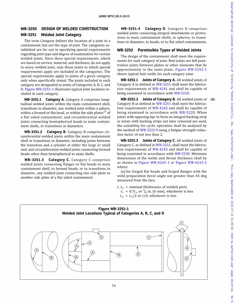
ð15Þ
WB-3250 DESIGN OF WELDED CONSTRUCTIONWB-3251 Welded Joint CategoryThe term Category defines the location of a joint in a
containment, but not the type of joint. The categories es-tablished are for use in specifying special requirementsregarding joint type and degree of examination for certainwelded joints. Since these special requirements, whichare based on service, material, and thickness, do not applyto every welded joint, only those joints to which specialrequirements apply are included in the categories. Thespecial requirements apply to joints of a given categoryonly when specifically stated. The joints included in eachcategory are designated as joints of Categories A, B, C, andD. Figure WB-3251-1 illustrates typical joint locations in-cluded in each category.
WB-3251.1 Category A. Category A comprises longi-tudinal welded joints within the main containment shell,transitions in diameter, any welded joint within a sphere,within a formed or flat head, or within the side plates23 ofa flat sided containment; and circumferential weldedjoints connecting hemispherical heads to main contain-ment shells, or transitions in diameters.
WB-3251.2 Category B. Category B comprises cir-cumferential welded joints within the main containmentshell or transitions in diameter, including joints betweenthe transition and a cylinder at either the large or smallend; and circumferential welded joints connecting formedheads other than hemispherical to main shells.
WB-3251.3 Category C. Category C compriseswelded joints connecting flanges or flat heads to maincontainment shell, to formed heads, or to transitions indiameter, any welded joint connecting one side plate toanother side plate of a flat sided containment.
WB-3251.4 Category D. Category D compriseswelded joints connecting integral attachments or protru-sions to main containment shells, to spheres, to transi-tions in diameter, to heads, or to flat sided containments.
WB-3252 Permissible Types of Welded Joints
The design of the containment shall meet the require-ments for each category of joint. Butt joints are full pene-tration joints between plates or other elements that lieapproximately in the same plane. Figure WB-3252-1shows typical butt welds for each category joint.
WB-3252.1 Joints of Category A. All welded joints ofCategory A as defined in WB-3251 shall meet the fabrica-tion requirements of WB-4241 and shall be capable ofbeing examined in accordance with WB-5210.
WB-3252.2 Joints of Category B. All welded joints ofCategory B as defined in WB-3251 shall meet the fabrica-tion requirements of WB-4242 and shall be capable ofbeing examined in accordance with WB-5220. Whenjoints with opposing lips to form an integral backing stripor joints with backing strips not later removed are used,the suitability for cyclic operation shall be analyzed bythe method of WB-3222.9 using a fatigue strength reduc-tion factor of not less than 2.
WB-3252.3 Joints of Category C. All welded joints ofCategory C, as defined in WB-3251, shall meet the fabrica-tion requirements of WB-4243 and shall be capable ofbeing examined in accordance with WB-5230. Minimumdimensions of the welds and throat thickness shall beas shown in Figure WB-4243-1 or Figure WB-4243-2where:(a) for forged flat heads and forged flanges with the
weld preparation bevel angle not greater than 45 degmeasured from the face:
t , tn = nominal thicknesses of welded partstc = 0.7tn or 1/4 in. (6 mm), whichever is lesstw = tn/2 or t/4, whichever is less
Figure WB-3251-1Welded Joint Locations Typical of Categories A, B, C, and D
A
A
A
A
D
A A
C
A
D
C
BB
74
ASME BPVC.III.3-2015
Copyrighted material licensed to University of Toronto by Thomson Scientific, Inc. (www.techstreet.com). This copy downloaded on 2015-07-14 21:45:42 -0500 by authorized user logan ahlstrom. No further reproduction or distribution is permitted.

Figure WB-3252-1Typical Butt Joints
75
ASME BPVC.III.3-2015
Copyrighted material licensed to University of Toronto by Thomson Scientific, Inc. (www.techstreet.com). This copy downloaded on 2015-07-14 21:45:42 -0500 by authorized user logan ahlstrom. No further reproduction or distribution is permitted.

ð15Þ
(b) for all other material forms and for forged flatheads, and forged flanges with the weld preparation bevelangle greater than 45 deg measured from the face:
t, tn = nominal thicknesses of welded partst c = 0.7tn or 1/4 in. (6 mm), whichever is lesstw = tn or t/2, whichever is less
(c) Hubs for butt welding to the adjacent shell, head, orother containment part, as in Figure WB-4243-2, shall notbe machined from rolled plate. The component having thehub shall be forged in such a manner as to provide in thehub the full minimum tensile strength and elongation spe-cified for the material, in a direction parallel to the axis ofthe vessel. Proof of this shall be furnished by a tensiontest specimen (subsize if necessary) taken in this direc-tion and as close to the hub as is practical. In FigureWB-4243-2, the minimum dimensions are as follows:
(1) sketch (a), r not less than 1.5tn(2) sketch (b), r not less than 1.5t n , and e not less
than tn(3) sketch (c), r not less than 1.5tn(4) sketch (d), t f not less than 2tn and r not less than
3t f(5) sketch (e), t f not less than 2tn , r not less than 3t f ,
and e not less than t f
WB-3252.4 Joints of Category D. All welded joints ofCategory D, as defined in WB-3251, shall be in accordancewith the requirements of one of (a) through (f) below.
(a) Full Penetration Welds. Full penetration welds, asshown in Figures WB-4244(a)-1, WB-4244(b)-1, andWB-4244(c)-1 may be used [except as otherwise pro-vided in (b)] for the purposes of achieving continuity ofmetal and facilitating the required radiographic examina-tion. When all or part of the required reinforcement is at-tributable to the connecting item, the connecting itemsshall be attached by full penetration welds through eitherthe containment shell or head, the thickness of the con-necting item, or both.
(b) Partial Penetration Welds
(1) Partial penetration welds, as shown in FigureWB-4244(d)-1, are allowed only for connecting items onwhich there are substantially no reaction loads, such asopenings for instrumentation. For such connecting items,all reinforcement shall be integral with the portion of thecontainment boundary penetrated. Partial penetrationwelds shall be of sufficient size to develop the fullstrength of the connecting items. Connecting items at-tached by partial penetration welds shall have an interfer-ence fit or a maximum diametric clearance between theitem and the containment boundary penetration of
(-a) 0.010 in. (0.25 mm) for d ≤ 1 in. (25 mm)
(-b) 0.020 in. (0.50 mm) for 1 in. (25 mm) < d ≤4 in. (100 mm)
(-c) 0.030 in. (0.76 mm) for d > 4 in. (100 mm)
where d is the outside diameter of the item, except thatthe above limits on maximum clearance need not bemet for the full length of the opening, provided there isa region at the weld preparation and a region near theend of the opening opposite the weld that does meetthe above limits on maximum clearance, and the latter re-gion is extensive enough (not necessarily continuous) toprovide a positive stop for deflection of the connectingitem.
(2) In satisfying the limit of WB-3222.6, the stress in-tensities resulting from pressure-induced strains (dila-tion of hole) may be treated as secondary in thepenetrating part of partial penetration welded construc-tion, provided the requirements of (f) and FigureWB-4244(d)-1 are fulfilled.(c) Butt-Welded Connections. Connections shall meet
the fabrication requirements of WB-4244(a) and shallbe capable of being examined in accordance withWB-5242. The minimum dimensions and geometrical re-quirements of Figure WB-4244(a)-1 shall be met, where
r1 = 1/4t or3/4 in. (19 mm), whichever is less
r2 = 1/4 in. (6 mm) minimumt = nominal thickness of part penetrated
tn = nominal thickness of penetrating part
(d) Full Penetration Corner-Welded Connections. Con-nections shall meet the fabrication requirements ofWB-4244(b) and shall be capable of being examined asrequired inWB-5243. The minimum dimensions of FigureWB-4244(b)-1 shall be met, where
r1 = 1/4t or3/4 in. (19 mm), whichever is less
r2 = 1/4 in. (6 mm) minimumt = nominal thickness of part penetratedt c = 0.7tn or 1/4 in. (6 mm), whichever is lesstn = nominal thickness of penetrating part
(e) Use of Deposited Weld Metal for Openings andConnections
(1) Connections shall meet the fabrication require-ments of WB-4244(c) and shall be capable of being exam-ined in accordance with WB-5244.
(2)When the deposited weld metal is used as rein-forcement, the coefficients of thermal expansion of thebase metal, the weld metal, and the connection shall notdiffer by more than 15% of the lowest coefficientinvolved.
(3) T h e m i n im um d im e n s i o n s o f F i g u r eWB-4244(c)-1 shall be met, where
r1 = 1/4t or3/4 in. (19 mm), whichever is less
t = nominal thickness of part penetratedt c = 0.7tn or 1/4 in. (6 mm), whichever is lesstn = nominal thickness of penetrating part
76
ASME BPVC.III.3-2015
Copyrighted material licensed to University of Toronto by Thomson Scientific, Inc. (www.techstreet.com). This copy downloaded on 2015-07-14 21:45:42 -0500 by authorized user logan ahlstrom. No further reproduction or distribution is permitted.

ð15Þ
(4) The corners of the end of each connection extend-
ing less than beyond the inner surface of the part
penetrated shall be rounded to a radius of one‐half thethickness tn of the connection or 3/4 in. (19 mm), which-ever is smaller.
(f) Attachment of Connections Using Partial PenetrationWelds
(1) Partial penetration welds used for connections aspermitted in (b) shall meet the fabrication requirementsof WB-4244(d) and shall be capable of being examinedin accordance with the requirements of WB-5245.
(2) T h e m i n im um d im e n s i o n s o f F i g u r eWB-4244(d)-1 shall be met where
d = outside diameter of the connecting itemr1 = 1/4tn or 3/4 in. (19 mm), whichever is lesst = nominal thickness of part penetratedtc = 0.7tn or 1/4 in. (6 mm), whichever is lesstn = nominal thickness of penetrating part
(3) The corners of the end of each connecting item,
extending less than beyond the inner surface of
the part penetrated, shall be rounded to a radius of one‐half of the thickness t n of the penetrating part or 3/4 in.(19 mm), whichever is smaller.
(4)Weld groove design for partial penetration jointsattaching connecting item may require special considera-tion to achieve the 1.25t n minimum depth of weld andadequate access for welding examination. The weldsshown in the sketches of Figure WB-4244(d)-1 may beon either the inside or the outside of the containmentshell. Weld preparation may be J‐groove, as shown inthe figures, or straight bevel.
(5) A fatigue strength reduction factor of not lessthan four shall be used when fatigue analysis is required.
WB-3254 Structural Attachment WeldsWelds for structural attachments shall meet the re-
quirements of WB-4430.
WB-3255 Welding GroovesThe dimensions and shape of the edges to be joined
shall be such as to permit complete fusion and completejoint penetration, except as otherwise permitted inWB-3252.4.
WB-3256 Thermal TreatmentAll containments and containment parts shall be given
the appropriate postweld heat treatment prescribed inWB-4620.
WB-3260 SPECIAL CONTAINMENTREQUIREMENTS
WB-3261 Category A or Category B JointsBetween Sections of UnequalThickness
In general, a tapered transition section as shown inFigure WB-3261-1, which is a type of gross structural dis-continuity (WB-3213.2), shall be provided at joints of Ca-tegories A and B between sections that differ in thicknessby more than one‐fourth the thickness of the thinner sec-tion. The transition section may be formed by any processthat will provide a uniform taper. An ellipsoidal or hemi-spherical head that has a greater thickness than a cylinderof the same inside diameter may be machined to the out-side diameter of the cylinder, provided the remainingthickness is at least as great as that required for a shellof the same diameter. A uniform taper is not requiredfor flanged hubs. The adequacy of the transition shall beevaluated by stress analysis. Stress intensity limitationsare given in WB-3220. The requirements of this para-graph do not apply to flange hubs.
WB-3700 STRAIN-BASED ACCEPTANCECRITERIA
The strain-based acceptance criteria are applicableonly to the metallic containments of transportationpackagings subject to energy-limited dynamic events. Itis not the intent of this subarticle to permit significant re-gions or major portions of the containment to experiencesstrains at or near the limits of these strain-based accep-tance criteria without consideration of the overall compo-nent deformation. These strain-based acceptance criteriaare established to address the regions of the containmentthat experience high strains due to the effects of direct im-pacts. Deformation limits, if any, provided in the DesignSpecification shall be satisfied.
Section III Appendices, Nonmandatory Appendix FFprovides the strain-based acceptance criteria.
77
ASME BPVC.III.3-2015
Copyrighted material licensed to University of Toronto by Thomson Scientific, Inc. (www.techstreet.com). This copy downloaded on 2015-07-14 21:45:42 -0500 by authorized user logan ahlstrom. No further reproduction or distribution is permitted.
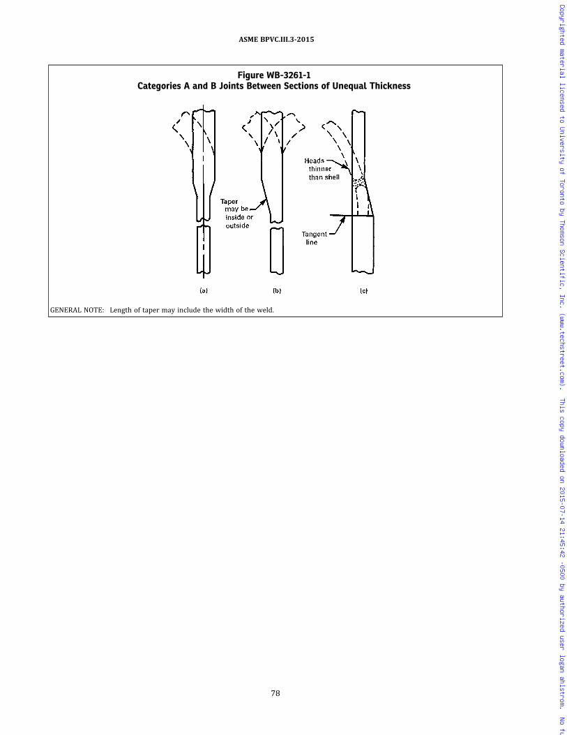
Figure WB-3261-1Categories A and B Joints Between Sections of Unequal Thickness
GENERAL NOTE: Length of taper may include the width of the weld.
78
ASME BPVC.III.3-2015
Copyrighted material licensed to University of Toronto by Thomson Scientific, Inc. (www.techstreet.com). This copy downloaded on 2015-07-14 21:45:42 -0500 by authorized user logan ahlstrom. No further reproduction or distribution is permitted.
ARTICLE WB-4000FABRICATION
WB-4100 GENERAL REQUIREMENTS
WB-4110 INTRODUCTION
Containments shall be fabricated and installed in accor-dance with the requirements of this Article and shall bemanufactured from materials that meet the requirementsof Article WB-2000.
WB-4120 CERTIFICATION OF MATERIALS ANDFABRICATION BY CERTIFICATEHOLDER
WB-4121 Means of Certification
The Certificate Holder for a containment shall certify,by application of the Certification Mark and completionof the appropriate Data Report in accordance with ArticleWA-8000, that the materials used comply with the re-quirements of Article WB-2000 and that the fabricationcomplies with the requirements of this Article.
WB-4121.1 Certification of Treatments, Tests, andExaminations. If the Certificate Holder or Subcontractorperforms treatments, tests, repairs, or examinations re-quired by this Division, the NPT or N3 Certificate Holdershall certify that this requirement has been fulfilled(NCA‐3860). Reports of all required treatments and ofthe results of all required tests, repairs, and examinationsperformed shall be available to the Inspector.
WB-4121.2 Repetition of Tensile or Impact Tests. Ifduring the fabrication of the containment the material issubjected to heat treatment that has not been coveredby treatment of the test coupons (WB-2200) and thatmay reduce either tensile or impact properties belowthe required values, the tensile and impact tests shall berepeated by the Certificate Holder on test specimens ta-ken from test coupons which have been taken and treatedin accordance with the requirements of Article WB-2000.
WB-4121.3 Repetition of Surface Examination AfterMachining. If, during the fabrication of a containment,materials are machined, then the Certificate Holder shallreexamine the surface of the material in accordance withWB-2500 when:
(a) the surface was required to be examined by themagnetic particle or liquid penetrant method in accor-dance with WB-2500; and
(b) the amount of material removed from the surfaceexceeds the lesser of 1/8 in. (3 mm) or 10% of the mini-mum required thickness of the item.
WB-4122 Material Identification
(a)Material performing a containment function shallcarry identification markings which will remain distin-guishable until the containment is assembled. If the origi-nal identification markings are cut off or the material isdivided, the marks shall either be transferred to the partscut or a coded marking shall be used to ensure identifica-tion of each piece of material during subsequent fabrica-tion. In either case, an as‐built sketch or a tabulation ofmaterials shall be made identifying each piece of materialwith the Certified Material Test Report, where applicable,and the coded marking. For studs, bolts, and nuts it is per-missible to identify the Certified Material Test Reports formaterial in each component or item in lieu of identifyingeach piece of material with the Certified Material Test Re-port and the coded marking. Material supplied with a Cer-tificate of Compliance, and welding material, shall beidentified and controlled so that they can be traced tothe containment, or else a control procedure shall be em-ployed which ensures that the specified materials areused.
(b)Material from which the identification marking islost shall be treated as nonconforming material until ap-propriate tests or other verifications are made and docu-mented to assure material identification. Testing isrequired unless positive identification can be made byother documented evidence. The material may then be re‐marked upon establishing positive identification.
WB-4122.1 Marking Material. Material shall bemarked in accordance with WB-2150.
WB-4123 Examinations
Visual examination activities that are not referenced forexamination by other specific Code paragraphs, and areperformed solely to verify compliance with requirementsof Article WB-4000, may be performed by the personswho perform or supervise the work. These visual exami-nations are not required to be performed by personneland procedures qualified to WB-5500 and WB-5100, re-spectively, unless so specified.
WB-4124 Additional Requirements WhenStrain-Based Acceptance Criteria HaveBeen Implemented
In order to satisfy the strain-based acceptance criteriaof WB-3700 regarding the locations of unique materialheats used in containment fabrication, traceability of all
79
ASME BPVC.III.3-2015
Copyrighted material licensed to University of Toronto by Thomson Scientific, Inc. (www.techstreet.com). This copy downloaded on 2015-07-14 21:45:42 -0500 by authorized user logan ahlstrom. No further reproduction or distribution is permitted.
unique material heats and their specific location(s) of useshall be established and documented in the final DesignReport and the as-built Design Drawings. This require-ment is only necessary when strain-based acceptance cri-ter ia have been employed in the design of thecontainment.
WB-4125 Testing of Welding MaterialAll welding material shall meet the requirements of
WB-2400.
WB-4130 REPAIR OF MATERIALWB-4131 Elimination and Repair of DefectsMaterial originally accepted on delivery in which de-
fects exceeding the limits of WB-2500 are known or dis-covered dur ing the proces s o f f abr i c a t i on i sunacceptable. The material may be used provided thecondition is corrected in accordance with the require-ments of WB-2500 for the applicable product form,except(a) the limitation on the depth of the weld repair does
not apply(b) the time of examination of the weld repairs to weld
edge preparations shall be in accordance with WB-5130
WB-4132 Documentation of Repair Welds of BaseMaterial
The Certificate Holder who makes a repair weld ex-ceeding in depth the lesser of 3/8 in. (10 mm) or 10% ofthe section thickness, shall prepare a report which shallinclude a chart which shows the location and size of theprepared cavity, the welding material identification, thewelding procedure, the heat treatment, and the examina-tion results of repair welds.
WB-4200 FORMING, FITTING, ANDALIGNING
WB-4210 CUTTING, FORMING, AND BENDINGWB-4211 CuttingMaterials may be cut to shape and size by mechanical
means, such as machining, shearing, chipping, or grinding,or by thermal cutting.
WB-4211.1 Preheating Before Thermal Cutting.When thermal cutting is performed to prepare weld jointsor edges, to remove attachments or defective material, orfor any other purpose, consideration shall be given to pre-heating the material, using preheat schedules such as sug-gested in Section III Appendices, NonmandatoryAppendix D.
WB-4212 Forming and Bending ProcessesAny process may be used to hot or cold form or bend
containment material, including weld metal, providedthe required dimensions are attained (see WB-4214 and
WB-4220), and provided the impact properties of the ma-terial, when required, are not reduced below the mini-mum specified values, or they are effectively restoredby heat treatment following the forming operation. Hotforming is defined as forming with the material tempera-ture higher than 100°F (38°C) below the lower transfor-mation temperature of the material.
WB-4213 Qualification of Forming Processes forImpact Property Requirements
A procedure qualification test shall be conducted usingspecimens taken from material of the same specification,grade or class, heat treatment, and with similar impactproperties, as required for the material in the contain-ment. These specimens shall be subjected to the equiva-lent forming or bending process and heat treatment asthe material in the containment. Applicable tests shallbe conducted to determine that the required impact prop-erties of WB-2300 are met after straining.
WB-4213.1 Exemptions. Procedure qualificationtests are not required for materials listed in (a) through(f) below:(a) hot formed material, such as forgings, in which the
hot forming is completed by the Material Organizationprior to removal of the impact test specimens;(b) hot formed material represented by test coupons
required in either WB-2211 or WB-4121.2, which havebeen subjected to heat treatment representing the hotforming procedure and the heat treatments to be appliedto the parts;(c) material that does not require impact tests in accor-
dance with WB-2300;(d)material that has a final strain less than 0.5%;(e) material where the final strain is less than that of a
previously qualified procedure for that material;(f) material from which the impact testing is required
by WB-2300 is performed on each heat and lot, as applic-able, after forming.
WB-4213.2 Procedure Qualification Test. The proce-dure qualification test shall be performed in the mannerstipulated in (a) through (f) below.(a) The tests shall be performed on three different
heats of material both before straining and after strainingand heat treatment to establish the effects of the formingand subsequent heat treatment operations.(b) Specimens shall be taken in accordance with the re-
quirements of Article WB-2000 and shall be taken fromthe tension side of the strained material.(c) The percent strain shall be established by the fol-
lowing equations:(1) For cylinders
80
ASME BPVC.III.3-2015
Copyrighted material licensed to University of Toronto by Thomson Scientific, Inc. (www.techstreet.com). This copy downloaded on 2015-07-14 21:45:42 -0500 by authorized user logan ahlstrom. No further reproduction or distribution is permitted.
(2) For spherical or dished surfaces
(3) For pipe
where
R = nominal bending radius to the center line of thepipe, in. (mm)
Rf = final radius to center line of shell, in. (mm)Ro = original radius (equal to infinity for a flat part), in.
(mm)r = nominal radius of the pipe, in. (mm)t = nominal thickness, in. (mm)
(d) The procedure qualification shall simulate the max-imum percent surface strain, employing a bending pro-cess similar to that used in the fabrication of thematerial or by direct tension on the specimen.
(e) Sufficient Cv test specimens shall be taken fromeach of the three heats of material to establish a transitioncurve showing both the upper and lower shelves. On eachof the three heats, tests consisting of three impact speci-mens shall be conducted at a minimum of five differenttemperatures distributed throughout the transition re-gion. The upper and lower shelves may be establishedby the use of one test specimen for each shelf. Dependingon the product form, it may be necessary to plot the tran-sition curves using both lateral expansion and energy lev-el data (WB-2300). In addition, drop weight tests shall bemade when required by WB-2300.
(f) Using the results of the impact test data from eachof three heats, taken both before and after straining, de-termine either:
(1) the maximum change in NDT temperature alongwith:
(-a) the maximum change of lateral expansion andenergy at the temperature under consideration; or
(-b) the maximum change of temperature at thelateral expansion and energy levels under consideration;or
(2)when lateral expansion is the acceptance criter-ion (WB-2300), either the maximum change in tempera-ture or the maximum change in lateral expansion.
WB-4213.3 Acceptance Criteria for Formed Materi-al. To be acceptable, the formed material used in the com-ponent shall have impact properties before formingsufficient to compensate for the maximum loss of impactproperties due to the qualified forming processes used.
WB-4213.4 Requalification. A new procedure quali-fication test is required when any of the changes in (a),(b), or (c) below are made.
(a) The actual postweld heat treatment time at tem-perature is greater than previously qualified consideringWB-2211. If the material is not postweld heat-treated,the procedure must be qualified without postweld heattreatment.
(b) The maximum calculated strain of the material ex-ceeds the previously qualified strain by more than 0.5%.
(c) Preheat over 250°F (120°C) is used in the formingor bending operation but not followed by a subsequentpostweld heat treatment.
WB-4214 Minimum Thickness of FabricatedMaterial
If any fabrication operation reduces the thickness be-low the minimum required to satisfy the rules of ArticleWB-3000, the material may be repaired in accordancewith WB-4130.
WB-4220 FORMING TOLERANCESWB-4221 Tolerance for Containment Shells
Cylindrical or spherical shells of a completed contain-ment vessel, except formed heads covered by WB-4222,shall meet the requirements of the following subpara-graphs at all cross sections, where not further limitedby design.
WB-4221.1 Maximum Difference in Cross-SectionalDiameters. The difference in inches (millimeters) be-tween the maximum andminimum diameters at any crosssection shall not exceed the smaller of (D + 50)/200,where D is the nominal inside diameter in inches[(D + 1 270)/200, where D is the nominal inside diameterin millimeters], and D/100, where D is the nominal insidediameter, in. (mm), at the cross section under considera-tion. The diameters may be measured on the inside oroutside of the containment cylindrical shell. If measuredon the outside, the diameters shall be corrected for theplate thickness at the cross section under consideration(Figure WB-4221.1-1). When the cross section passesthrough an opening, the permissible difference in insidediameters given herein may be increased by 2% of the in-side diameter of the opening.
WB-4221.2 Maximum Deviation From True Theore-tical Form for External Pressure. Containments designedfor external pressure shall meet the tolerances given in(a) through (e) below.
(a) The maximum plus or minus deviation from thetrue circular form of cylinders or the theoretical form ofother shapes, measured radially on the outside or insideof the component, shall not exceed the maximum permis-sible deviation obtained from Figure WB-4221.2(a)-1.Measurements shall be made from a segmental circulartemplate having the design inside or outside radius de-pending on where the measurements are taken and achord length equal to twice the arc length obtained fromFigure WB-4221.2(a)-2. For Figure WB-4221.2(a)-1, themaximum permissible deviation e need not be less than
81
ASME BPVC.III.3-2015
Copyrighted material licensed to University of Toronto by Thomson Scientific, Inc. (www.techstreet.com). This copy downloaded on 2015-07-14 21:45:42 -0500 by authorized user logan ahlstrom. No further reproduction or distribution is permitted.

0.3t . For Figure WB-4221.2(a)-2, the arc length need notbe greater than 0.30Do . Measurements shall not be takenon welds or other raised parts.(b) The value of t , in., at any cross section is the nom-
inal plate thickness less corrosion allowance for sectionsof constant thickness and the nominal thickness of thethinnest plate less corrosion allowance for sections hav-ing plates of more than one thickness.
(c) The value of L in Figures WB-4221.2(a)-1 andWB-4221.2(a)-2 is determined by (1) and (2) below.
(1) For cylinders, L is the total length, in., of the de-sign length of a containment section, taken as the largestof the following:
(-a) the distance between head tangent lines plusone‐third of the depth of each head if there are no stiffen-ing rings;
(-b) the greatest center‐to‐center distance be-tween any two adjacent stiffening rings; or
(-c) the distance from the center of the first stif-fening ring to the head tangent line plus one‐third ofthe depth of the head, all measured parallel to the axisof the containment, in.
(2) For spheres, L is one‐half of the outside diameterDo , in.(d) The dimensions of a completed containment may be
brought within the requirements by any process whichwill not impair the strength of the material.(e) Sharp bends and flat spots shall not be permitted
unless provision is made for them in the design.
WB-4221.3 Deviations From Tolerances. Deviationsfrom the tolerance requirements st ipulated inWB-4221.1 and WB-4221.2 are permitted, provided thedrawings are modified and deviations are reconciled with
Figure WB-4221.1-1Maximum Difference in Cross-Sectional
Diameters
Figure WB-4221.2(a)-1Maximum Permissible Deviation e From a True Circular Form
0.10 0.2 0.3 0.4 0.5 0.6 0.8 25
30
40
1,000
Design Length � Outside Diameter, L/Do
Ou
tsid
e D
iam
eter
� T
hic
knes
s, D
o/t
1.0 2 3 4 5 6 7 8 9 10
50
60 70 80 90
100
200
300
400
500
600 700 800 900
e � 1.0te � 0.8t
e � 0.6te � 0.5t
e � 0.4t
e � 0.3t
82
ASME BPVC.III.3-2015
Copyrighted material licensed to University of Toronto by Thomson Scientific, Inc. (www.techstreet.com). This copy downloaded on 2015-07-14 21:45:42 -0500 by authorized user logan ahlstrom. No further reproduction or distribution is permitted.

the calculations and the licensing documents. Deviationsare permitted, provided Design Documents (WA-3350)and corrective actions are certified by a registered profes-sional engineer in an addendum to the Design Report.
WB-4221.4 Tolerance Deviations for ContainmentParts Fabricated From Pipe. Containments subjected toeither internal or external pressure and fabricated frompipe, meeting all other requirements of this Subsection,may have variations of diameter and deviations from cir-cularity permitted by the specification for such pipe.
WB-4222 Tolerances for Formed Vessel Heads
The tolerance for formed vessel heads shall be as setforth in the following subparagraphs.
WB-4222.1 Maximum Difference in Cross-SectionalDiameters. The skirt or cylindrical end of a formed headshall be circular to the extent that the difference in inches(millimeters) between the maximum and minimum dia-meters does not exceed the lesser of (D + 50)/200, whereD is the nominal inside diameter in inches [(D + 1 270)/200, where D is the nominal inside diameter in milli-meters] and (D + 12)/100, where D is the nominal insidediameter in inches [(D + 300)/100, where D is the
nominal inside diameter in millimeters], and shall matchthe cylindrical edge of the adjoining part within the align-ment tolerance specified in WB-4232.
WB-4222.2 Deviation From Specified Shape.(a) The inner surface of a torispherical or ellipsoidal
head shall not deviate outside the specified shape bymore than 11/4% of D , inside the specified shape by morethan 5/8% of D , where D is the nominal inside diameter ofthe containment. Such deviations shall be measured per-pendicular to the specified shape and shall not be abrupt.The knuckle radius shall not be less than specified. For 2:1ellipsoidal heads, the knuckle radius may be consideredto be 17% of the diameter of the containment.
(b) Hemispherical heads and any spherical portion of aformed head shall meet the local tolerances for spheres asgiven in WB-4221.2, using L as the outside spherical ra-dius, in. (mm), and Do as two times L .
(c) Deviation measurements shall be taken on the sur-face of the base material and not on welds.
Figure WB-4221.2(a)-2Maximum ARC Length for Determining Plus or Minus Deviation
0.01 0.02 0.2 0.4 0.6 0.04 0.06 1.0 0.10 10
20
2,000
Design Length � Outside Diameter, L/Do
Ou
tsid
e D
iam
eter
� T
hic
knes
s, D
o/t
60 50 40
30
80
100
200
300
400 500 600
1,000
800
2 3 4 5 6 8 10 20
Arc
� 0
.030
D o
Arc
� 0
.040
D o
Arc
� 0
.045
D oA
rc �
0.0
55D o
Arc
� 0
.065
D o
Arc
� 0
.075
D o
Arc
� 0
.085
D o
Arc
� 0
.10D
o
Arc
� 0
.200
D o
Arc
� 0
.300
D o
Arc
� 0
.250
D o
Arc
� 0
.125
D oA
rc �
0.1
75D o
Arc
� 0
.150
D o
Arc
� 0
.035
D o
83
ASME BPVC.III.3-2015
Copyrighted material licensed to University of Toronto by Thomson Scientific, Inc. (www.techstreet.com). This copy downloaded on 2015-07-14 21:45:42 -0500 by authorized user logan ahlstrom. No further reproduction or distribution is permitted.

WB-4230 FITTING AND ALIGNINGWB-4231 Fitting and Aligning Methods
Parts that are to be joined by welding may be fitted,aligned, and retained in position during the welding op-eration by the use of bars, jacks, clamps, tack welds, ortemporary attachments.
WB-4231.1 Tack Welds. Tack welds used to securealignment shall either be removed completely, when theyhave served their purpose, or their stopping and startingends shall be properly prepared by grinding or other sui-table means so that they may be satisfactorily incorpo-rated into the final weld. Tack welds shall be made byqualified welders using qualified welding procedures.When tack welds are to become part of the finished weld,they shall be visually examined and defective tack weldsshall be removed.
WB-4232 Alignment Requirements WhenContainments Are Welded From TwoSides
(a) Alignment of sections which are welded from twosides shall be such that the maximum offset of the fin-ished weld will not be greater than the applicable amountlisted in Table WB-4232-1, where t is the nominal thick-ness of the thinner section at the joint.
(b) Joints in spherical containments or within heads,and joints between cylindrical shells and hemisphericalheads shall meet the requirements in Table WB-4232-1for longitudinal joints.
WB-4232.1 Fairing of Offsets. Any offset within theallowable tolerance provided above shall be faired to atleast a 3:1 taper over the width of the finished weld or,if necessary, by adding additional weld metal beyondwhat would otherwise be the edge of the weld. In addi-tion, offsets greater than those stated in TableWB-4232-1 are acceptable provided the requirements ofWB-3200 are met.
WB-4233 Alignment Requirements When InsideSurfaces Are Inaccessible
(a)When the inside surfaces of items are inaccessiblefor welding or fairing in accordance with WB-4232, align-ment of sections shall meet the requirements of (1) and(2) below:
(1) See (-a) and (-b) below.(-a) For circumferential joints the inside dia-
meters shall match each other within 1/16 in. (1.5 mm).When the items are aligned concentrically, a uniform mis-match of 1/32 in. (0.8 mm) all around the joint can result asshown in Figure WB-4233(a)-1 sketch (a). However,other variables not associated with the diameter of theitem often result in alignments that are offset rather thanconcentric. In these cases, the maximum misalignment atany one point around the joint shall not exceed 3/32 in.(2.5 mm) as shown in Figure WB-4233(a)-1 sketch (b).Should tolerances on diameter, wall thickness, out‐of‐roundness, etc., result in inside diameter variationswhich do not meet these limits, the inside diameters shallbe counterbored, sized, or ground to produce a bore with-in these limits, provided a gradual change in thicknessfrom the item to adjoining items is maintained. Any weld-ing transition is acceptable, provided the wall thickness inthe transition region is not less than the minimum wallthickness of the containment or item and sharp reentrantangles and abrupt changes in slope in the transition re-gion are avoided.
(-b) Offset of outside surfaces shall be faired to atleast a 3:1 taper over the width of the finished weld or, ifnecessary, by adding additional weld metal.
(2) For longitudinal joints the misalignment of insidesurfaces shall not exceed 3/32 in. (2.5 mm) and the offset ofoutside surfaces shall be faired to at least a 3:1 taper overthe width of the finished weld or, if necessary, by addingadditional weld metal.(b) Single-welded joints may meet the alignment re-
quirements of (a)(1) and (a)(2) above in lieu of the re-quirements of WB-4232.
WB-4240 REQUIREMENTS FOR WELD JOINTS INCONTAINMENTS
WB-4241 Category A Weld Joints inContainments
Category A weld joints containments shall be full pene-tration butt joints. Joints that have been welded from oneside with backing that has been removed and thosewelded from one side without backing are acceptable asfull penetration welds provided the weld root side ofthe joints meets the requirements of WB-4424.
WB-4242 Category B Weld Joints inContainments
Category B weld joints in containments shall be full pe-netration butt joints. When used, backing strips shall becontinuous in cross section. Joints prepared with
Table WB-4232-1Maximum Allowable Offset in Final Welded
Joints
Section Thickness, in. (mm)
Direction of Joints
Longitudinalin. (mm)
Circumferentialin. (mm)
Up to 1/2 (13), incl.1/4t
1/4tOver 1/2 to
3/4 (13 to 19), incl. 1/8 (3)1/4t
Over 3/4 to 11/2 (19 to 38), incl. 1/8 (3)3/16 (5)
Over 11/2 to 2 (38 to 50), incl. 1/8 (3)1/8t
Over 2 (50) Lesser of 1/16t or3/8 (10)
Lesser of 1/8t or3/4
(19)
84
ASME BPVC.III.3-2015
Copyrighted material licensed to University of Toronto by Thomson Scientific, Inc. (www.techstreet.com). This copy downloaded on 2015-07-14 21:45:42 -0500 by authorized user logan ahlstrom. No further reproduction or distribution is permitted.
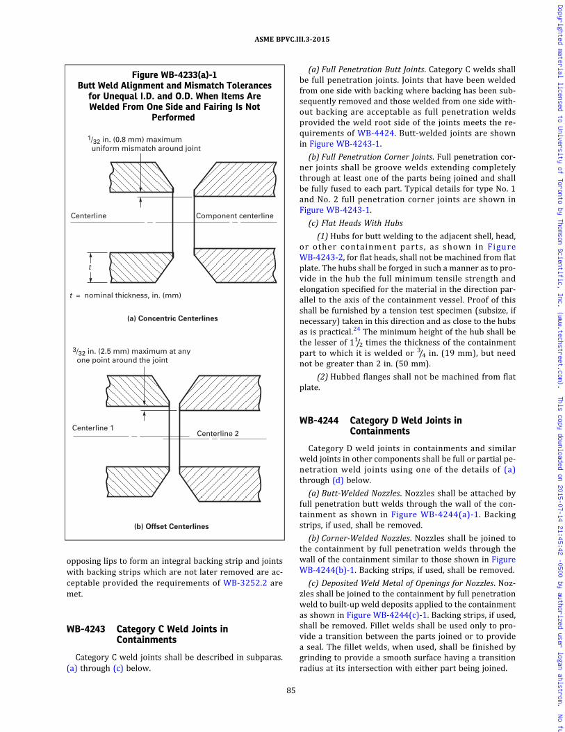
opposing lips to form an integral backing strip and jointswith backing strips which are not later removed are ac-ceptable provided the requirements of WB-3252.2 aremet.
WB-4243 Category C Weld Joints inContainments
Category C weld joints shall be described in subparas.(a) through (c) below.
(a) Full Penetration Butt Joints. Category C welds shallbe full penetration joints. Joints that have been weldedfrom one side with backing where backing has been sub-sequently removed and those welded from one side with-out backing are acceptable as full penetration weldsprovided the weld root side of the joints meets the re-quirements of WB-4424. Butt-welded joints are shownin Figure WB-4243-1.
(b) Full Penetration Corner Joints. Full penetration cor-ner joints shall be groove welds extending completelythrough at least one of the parts being joined and shallbe fully fused to each part. Typical details for type No. 1and No. 2 full penetration corner joints are shown inFigure WB-4243-1.
(c) Flat Heads With Hubs
(1) Hubs for butt welding to the adjacent shell, head,or other containment parts, as shown in FigureWB-4243-2, for flat heads, shall not be machined from flatplate. The hubs shall be forged in such a manner as to pro-vide in the hub the full minimum tensile strength andelongation specified for the material in the direction par-allel to the axis of the containment vessel. Proof of thisshall be furnished by a tension test specimen (subsize, ifnecessary) taken in this direction and as close to the hubsas is practical.24 The minimum height of the hub shall bethe lesser of 11/2 times the thickness of the containmentpart to which it is welded or 3/4 in. (19 mm), but neednot be greater than 2 in. (50 mm).
(2) Hubbed flanges shall not be machined from flatplate.
WB-4244 Category D Weld Joints inContainments
Category D weld joints in containments and similarweld joints in other components shall be full or partial pe-netration weld joints using one of the details of (a)through (d) below.
(a) Butt-Welded Nozzles. Nozzles shall be attached byfull penetration butt welds through the wall of the con-tainment as shown in Figure WB-4244(a)-1. Backingstrips, if used, shall be removed.
(b) Corner-Welded Nozzles. Nozzles shall be joined tothe containment by full penetration welds through thewall of the containment similar to those shown in FigureWB-4244(b)-1. Backing strips, if used, shall be removed.
(c) Deposited Weld Metal of Openings for Nozzles. Noz-zles shall be joined to the containment by full penetrationweld to built‐up weld deposits applied to the containmentas shown in Figure WB-4244(c)-1. Backing strips, if used,shall be removed. Fillet welds shall be used only to pro-vide a transition between the parts joined or to providea seal. The fillet welds, when used, shall be finished bygrinding to provide a smooth surface having a transitionradius at its intersection with either part being joined.
Figure WB-4233(a)-1Butt Weld Alignment and Mismatch Tolerances
for Unequal I.D. and O.D. When Items AreWelded From One Side and Fairing Is Not
Performed
Centerline 2Centerline 1
(b) Offset Centerlines
3/32 in. (2.5 mm) maximum at any one point around the joint
Component centerlineCenterline
t = nominal thickness, in. (mm)
t
(a) Concentric Centerlines
1/32 in. (0.8 mm) maximum uniform mismatch around joint
85
ASME BPVC.III.3-2015
Copyrighted material licensed to University of Toronto by Thomson Scientific, Inc. (www.techstreet.com). This copy downloaded on 2015-07-14 21:45:42 -0500 by authorized user logan ahlstrom. No further reproduction or distribution is permitted.
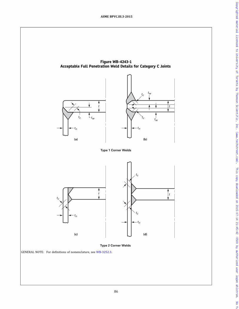
Figure WB-4243-1Acceptable Full Penetration Weld Details for Category C Joints
Type 2 Corner Welds
t
tw tc
tw tw tc
tn
t
tc
tn
t
tc
tc
tn
t tc
tn
(c) (d)
Type 1 Corner Welds
(a) (b)
GENERAL NOTE: For definitions of nomenclature, see WB-3252.3.
86
ASME BPVC.III.3-2015
Copyrighted material licensed to University of Toronto by Thomson Scientific, Inc. (www.techstreet.com). This copy downloaded on 2015-07-14 21:45:42 -0500 by authorized user logan ahlstrom. No further reproduction or distribution is permitted.

(d) Partial Penetration Welded Nozzles. Partial penetra-tion welds in containments shall meet the weld design re-quirements of WB-3252.4(f). Nozzles shall be attached asshown in Figures WB-4244(d)-1.
WB-4300 WELDING QUALIFICATIONS
WB-4310 GENERAL REQUIREMENTSWB-4311 Types of Processes Permitted
(a) Only those welding processes which are capable ofproducing welds in accordance with the welding proce-dure qualification requirements of Section IX and thisSubsection may be used for welding containment materialor attachments thereto. Any process used shall be such
that the records required by WB-4320 can be prepared,except that records for stud welds shall be traceable tothe welders and welding operators and not necessarilyto each specific weld.
(b) This Subsection does not permit the use of inertiaand continuous drive friction welding, specially designedseal welds, electroslag, or electrogas welding.
WB-4311.1 Stud Welding Restrictions. Stud weldingis acceptable only for nonstructural and temporary at-tachments (WB-4435). Studs shall be limited to 1 in.(25 mm) maximum diameter for round studs and anequivalent cross‐sectional area for studs of other shapeswhen welding in the flat position and 3/4 in. (19 mm) dia-meter for all other welding positions. Postweld heat
Figure WB-4243-2Typical Flat Heads With Hubs
Tension test specimen
Tension test specimen
Tension test specimen
tn
tf
r
(a) (b) (c)
t t
Tension test specimen
r rrtn
tn
(d)
t
tf
tn
tn
(e)
t
e
e
r
r
GENERAL NOTE: For definitions of nomenclature, see WB-3252.3(c).
87
ASME BPVC.III.3-2015
Copyrighted material licensed to University of Toronto by Thomson Scientific, Inc. (www.techstreet.com). This copy downloaded on 2015-07-14 21:45:42 -0500 by authorized user logan ahlstrom. No further reproduction or distribution is permitted.
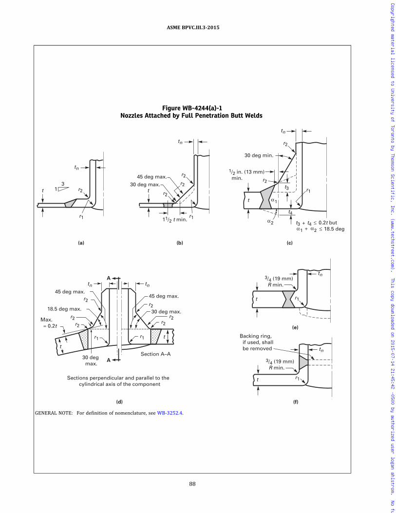
Figure WB-4244(a)-1Nozzles Attached by Full Penetration Butt Welds
t
t t 1 3 30 deg max.
11/2 t min.
1/2 in. (13 mm) min.
3/4 (19 mm) R min.
45 deg max.
30 deg min.
(c) (b) (a)
r1 r1
r2 r2
r2 r2
r1
r2
t3
t4
r2
tn
tn
tn
t
(e)
r1
tn
2
1
t3 t4 0.2t but 1 2 18.5 deg
3/4 (19 mm) R min.
Backing ring, if used, shall be removed
t
t
(f)
r1
tn
(d)
A
A
r2
r1 r1
r2
r2
r2
t
r2
r2
tn tn
45 deg max. 45 deg max.
30 deg max. 18.5 deg max.
Max. = 0.2t
30 deg max.
Section A–A
Sections perpendicular and parallel to the cylindrical axis of the component
GENERAL NOTE: For definition of nomenclature, see WB-3252.4.
88
ASME BPVC.III.3-2015
Copyrighted material licensed to University of Toronto by Thomson Scientific, Inc. (www.techstreet.com). This copy downloaded on 2015-07-14 21:45:42 -0500 by authorized user logan ahlstrom. No further reproduction or distribution is permitted.

Figure WB-4244(b)-1Nozzles Attached by Full Penetration Corner Welds
GENERAL NOTE: For definition of nomenclature, see WB-3252.4.
89
ASME BPVC.III.3-2015
Copyrighted material licensed to University of Toronto by Thomson Scientific, Inc. (www.techstreet.com). This copy downloaded on 2015-07-14 21:45:42 -0500 by authorized user logan ahlstrom. No further reproduction or distribution is permitted.

Figure WB-4244(c)-1Deposited Weld Metal Used as Reinforcement of Openings for Nozzles
r1
3/4 in. (19 mm) min.
3/4 in. (19 mm) min.
3/4 in. (19 mm) min.
Backing ring, if used, shall be removed
tn
tc
t
tn
tn
t
tn
t
r1
r1
Backing ring, if used, shall be removed
t
tn
r1
t
3/4 in. (19 mm) min.
Step 2(a)Step 1
Step 2(b)Step 1
Step 2(c)Step 1
Step 2(d)Step 1
tn
t
GENERAL NOTE: For definition of nomenclature, see WB-3252.4.
90
ASME BPVC.III.3-2015
Copyrighted material licensed to University of Toronto by Thomson Scientific, Inc. (www.techstreet.com). This copy downloaded on 2015-07-14 21:45:42 -0500 by authorized user logan ahlstrom. No further reproduction or distribution is permitted.

treatment shall comply with WB-4600, except that timeat temperature need not exceed 1/2 hr regardless of basematerial thickness. Welding procedure and performancequalification shall comply with the requirements of Sec-tion IX.
WB-4311.2 Capacitor Discharge Welding. Capacitordischarge welding may be used for welding temporary at-tachments and permanent nonstructural attachmentsprovided:
(a) temporary attachments are removed in accordancewith the provisions of WB-4435(b); and
(b) the energy output for permanent nonstructural at-tachments such as strain gages and thermocouples is lim-ited to 125 W‐sec, and the minimum thickness of thematerial to which the attachment is made is greater than0.09 in. (2.3 mm); and
(c) a Welding Procedure Specification is prepared de-scribing the capacitor discharge equipment, the combina-tion of materials to be joined, and the technique ofapplication; qualification of the welding procedure isnot required.
WB-4320 WELDING QUALIFICATIONS, RECORDS,AND IDENTIFYING STAMPS
WB-4321 Required Qualifications(a) Each Certificate Holder is responsible for the weld-
ing done by his organization, and each Certificate Holdershall establish the procedure and conduct the tests re-quired by this Article and by Section IX in order to qualifyboth the welding procedures and the performance ofwelders and welding operators who apply theseprocedures.
(b) Procedures, welders, and welding operators used tojoin permanent or temporary attachments to contain-ments and to make permanent or temporary tack weldsused in such welding shall also meet the qualification re-quirements of this Article.
(c) When making procedure test plates for butt welds,consideration shall be given to the effect of angular, lat-eral, and end restraint on the weldment. This applies par-ticularly to material and weld metal of 80.0 ksi (550 MPa)tensile strength or higher and heavy sections of both lowand high tensile strength material. The addition of re-straint during welding may result in cracking difficultiesthat otherwise might not occur.
(d)WA-3131 provides specific additional requirementswhen welding services are subcontracted to or throughorganizations not holding an appropriate Certificate ofAuthorization.
Figure WB-4244(d)-1Nozzles Attached by Partial Penetration Welds
11/2 tn min.
1.25 tn min.
r1t
tnd
Welding buildup added, when required, to meet reinforcement limitations [Notes (2) and (3)]
1.25 tn min.
(c)(b)(a)
r1
t
tn
tc
d
3/4 tn min. [Note (1)] r1
t
tn
tc
d
GENERAL NOTE: For definitions of symbols and other related requirements, see WB-3252.4.
NOTES:(1) The 3/4tn minimum dimension applies to the fillet leg and the J‐groove depth.(2) Weld deposit reinforcement, if used, shall be examined as required by WB-5244.(3) Weld buildups are not attached to the nozzle.
91
ASME BPVC.III.3-2015
Copyrighted material licensed to University of Toronto by Thomson Scientific, Inc. (www.techstreet.com). This copy downloaded on 2015-07-14 21:45:42 -0500 by authorized user logan ahlstrom. No further reproduction or distribution is permitted.

ð15Þ
WB-4322 Maintenance and Certification ofRecords
The Certificate Holder shall maintain a record of thequalified welding procedures and of the welders andwelding operators qualified by him, showing the dateand results of tests and the identification mark assignedto each welder. These records shall be reviewed, verified,and certified by the Certificate Holder by signature orsome other method of control in accordance with the Cer-tificate Holder’s Quality Assurance Program and shall beavailable to the Authorized Nuclear Inspector.
WB-4322.1 Identification of Joints by Welder orWelding Operator.
(a) Each welder or welding operator shall apply theidentification mark assigned by the Certificate Holderon or adjacent to all permanent welded joints or seriesof joints on which he welds. The marking shall be at inter-vals of 3 ft (1 m) or less and shall be done with eitherblunt nose continuous or blunt nose interrupted dot diestamps. As an alternative, the Certificate Holder shallkeep a record of permanent welded joints in each itemand of the welders and welding operators used in makingeach of the joints.
(b)When a multiple number of permanent structuralattachment welds, nonstructural welds, fillet welds, sock-et welds, weld metal cladding, and hard surfacing aremade on the containment, the Certificate Holder neednot identify the welder or welding operator who weldedeach individual joint, provided the following applies:
(1) the Certificate Holder maintains a system thatwill identify the welders or welding operators who madesuch welds on the containment so that the Inspector canverify that the welders or welding operators were allproperly qualified;
(2) the welds in each category are all of the sametype and configuration and are welded with the sameWelding Procedure Specification.
WB-4323 Welding Prior to Qualifications
No welding shall be undertaken until after the weldingprocedures which are to be used have been qualified.Only welders and welding operators who are qualifiedin accordance with WB-4320 and Section IX shall be used.
WB-4324 Transferring Qualifications
The welding procedure qualifications and the perfor-mance qualification tests for welders and welding opera-tors conducted by one Certificate Holder shall not qualifywelding procedures and shall not qualify welders orwelding operators to weld for any other CertificateHolder, except as provided in Section IX.
WB-4330 GENERAL REQUIREMENTS FORWELDING PROCEDUREQUALIFICATION TESTS
WB-4331 Conformance to Section IXRequirements
All welding procedure qualification tests shall be in ac-cordance with the requirements of Section IX as supple-mented or modified by the requirements of this Article.
WB-4333 Heat Treatment of Qualification Weldsfor Ferritic Materials
Postweld heat treatment of procedure qualificationwelds shall conform to the applicable requirements ofWB-4600 and Section IX. The postweld heat treatmenttime at temperature shall be at least 80% of the maximumtime to be applied to the component weld material. Thepostweld heat treatment total time may be applied inone heating cycle.
WB-4334 Preparation of Test Coupons andSpecimens
(a) Removal of test coupons from the test weld and thedimensions of specimens made from them shall conformto the requirements of Section IX, except that the removalof impact test coupons and the dimensions of impact testspecimens shall be in accordance with (b) below.(b)Weld deposit of each process in a multiple process
weld shall, where possible, be included in the impact testspecimens. When each process cannot be included in thefull‐size impact test specimen at the 1/4t location requiredby this Subsection, additional full‐size specimens shall beobtained from locations in the test weld that will ensurethat at least a portion of each process has been includedin full‐size test specimens. As an alternative, additionaltest welds can be made with each process so that full‐sizespecimens can be tested for each process.
WB-4334.1 Coupons Representing the Weld Depos-it. Impact test specimens and testing methods shall con-form to WB-2321. The impact specimen shall be locatedso that the longitudinal axis of the specimen is at least0.25t and, where the thickness of the test assembly per-mits, not less than 3/8 in. (10 mm) from the weld surfaceof the test assembly. In addition, when the postweld heattreatment temperature exceeds the maximum tempera-ture specified in WB-4620 and the test assembly is cooledat an accelerated rate, the longitudinal axis of the speci-men shall be a minimum of t from the edge of the test as-sembly. The specimen shall be transverse to thelongitudinal axis of the weld with the area of the notch lo-cated in the weld. The length of the notch of the CharpyV‐notch specimen shall be normal to the surface of theweld. Where drop weight specimens are required, thetension surface of the specimen shall be oriented parallelto the surface of the test weld assembly.
92
ASME BPVC.III.3-2015
Copyrighted material licensed to University of Toronto by Thomson Scientific, Inc. (www.techstreet.com). This copy downloaded on 2015-07-14 21:45:42 -0500 by authorized user logan ahlstrom. No further reproduction or distribution is permitted.

W B - 4 3 3 4 . 2 C o u p o n s R e p r e s e n t i n g t h eHeat-Affected Zone. Where impact tests of theheat-affected zone are required byWB-4335.2, specimensshall be taken from the welding procedure qualificationtest assemblies in accordance with (a) through (c) below.
(a) If the qualification test material is in the form of aplate or a forging, the axis of the weld shall be orientedin the direction parallel to the principal direction of roll-ing or forging.
(b) The heat-affected zone impact test specimens andtesting methods shall conform to the requirements ofWB-2321.2. The specimens shall be removed from a loca-tion as near as practical to a depth midway between thesurface and center thickness . The coupons forheat-affected zone impact specimens shall be taken trans-verse to the axis of the weld and etched to define theheat-affected zone. The notch of the Charpy V‐notch spe-cimen shall be cut approximately normal to the materialsurface in such a manner as to include as muchheat-affected zone as possible in the resulting fracture.Where the material thickness permits, the axis of a speci-menmay be inclined to allow the root of the notch to alignparallel to the fusion line.
(c) For the comparison of heat-affected zone valueswith base material values [WB-4335.2(b)], CharpyV‐notch specimens shall be removed from the unaffectedbase material at approximately the same distance fromthe base material surface as the heat-affected zone speci-mens. The axis of the unaffected base material specimensshall be parallel to the axis of the heat-affected zone speci-mens, and the axis of the notch shall be normal to the sur-f a ce o f the base mate r i a l . When requ i red byWB-4335.2(b), drop‐weight specimens shall be removedfrom a depth as near as practical to midway betweenthe surface and center thickness of the unaffected basematerial and shall be tested in accordance with the re-quirements of WB-2321.1.
WB-4335 Impact Test Requirements
When materials are required to be impact tested perWB-2300 , impact tes ts of the weld meta l andheat-affected zone shall be performed in accordance withthe following subparagraphs. The weld procedure qualifi-cation impact test specimens shall be prepared and testedin accordance with the applicable requirements ofWB-2330 and WB-4334. Retests in accordance with theprovisions of WB-2350 are permitted.
WB-4335.1 Impact Tests of Weld Metal.(a) Impact tests of the weld metal shall be required for
welding procedure qualification tests for production weldjoints exceeding 5/8 in. (16 mm) in thickness when theweld will be made on the surface or penetrate base mate-rial that requires impact testing in accordance withWB-2310. In addition, such testing of the weld metal is re-quired for the welding procedure qualification tests forany weld repair to base material that requires impact
testing in accordance with WB-2310, regardless of thedepth of the repair. Exemption from impact testing underWB-2311(a) does not apply to weld metal of welding pro-cedure qualification tests for either production weldjoints or base metal repairs unless the specific weld metalused is A‐No. 8.
(b) The impact test requirements and acceptance stan-dards for welding procedure qualification weld metalshall be the same as specified in WB-2330 for the basematerial to be welded or repaired. Where two materialsare to be joined by welding and have different fracturetoughness requirements, the test requirements and ac-ceptance standards of either material may be used forthe weld metal except where this is otherwise specifiedin the Design Specification.
(c) Impact tests are not required for austenitic andnonferrous weld metal.
(d) A Welding Procedure Specification qualified to theimpact testing requirements of Division 1, SubsectionNB or NE may be accepted as an alternative to the Weld-ing Procedure Specification impact testing requirementsof this Subsection.
WB-4335.2 Impact Tests of Heat-Affected Zone.(a) Charpy V‐notch tests of the heat-affected zone of the
welding procedure qualification test assembly are re-quired whenever the thickness of the weld exceeds5/8 in. (16 mm) and either of the base materials requireimpact testing in accordance with the rules of WB-2310.The only exceptions to the requirements are thefollowing:
(1) the qualification for welds in P‐Nos. 1 and 3 andSA-336 F12 materials that are postweld heat-treated.
(2) the qualification for weld deposit cladding.(3) that portion of the heat-affected zone associated
with GTAW root deposits with a maximum of two layersor 3/16 in. (5 mm) thickness, whichever is less.
(b) The required testing shall be in accordance with (c)below for base material tested under WB-2331 orWB-2332(b) and in accordance with (d) below for basematerial tested under WB-2332(a).
(c) For heat affected zones associated with base mate-rial tested under WB-2331 or WB-2332(b), the requiredtesting shall be in accordance with (1) through (7).
(1) Determine the TNDT of the unaffected base mate-rial to be used in the welding procedure qualification testassembly.
(2) Charpy V‐notch test specimens representing boththe heat-affected zone and the unaffected base materialshall be tested. The unaffected base material specimensshall be tested at the (TND T + 60°F) (TNDT + 33°C)temperature.
(3) The Charpy V‐notch tests of the unaffected basematerial shall meet the applicable requirements ofWB-2330 or additional testing shall be performed at high-er temperatures until the requirements of WB-2330 aremet.
93
ASME BPVC.III.3-2015
Copyrighted material licensed to University of Toronto by Thomson Scientific, Inc. (www.techstreet.com). This copy downloaded on 2015-07-14 21:45:42 -0500 by authorized user logan ahlstrom. No further reproduction or distribution is permitted.

(4) The heat-affected zone specimens shall be testedat the test temperature determined in (3). The averagelateral expansion value of the specimens shall equal or ex-ceed the average lateral expansion value of the unaffectedbase material. For this case, the qualification test is ac-ceptable for the essential and supplemental essential vari-ables recorded on the welding procedure qualificationrecord. If the heat-affected zone average lateral expansionvalue is less than the unaffected base material lateral ex-pansion value, the adjustment given in (5) through (7)shall be determined and applied as provided in (e). Alter-natively, another test coupon may be welded and tested.
(5) Additional Charpy V‐notch tests shall be per-formed on either the heat‐affected zone or the unaffectedbase material, or both, at temperatures where the lateralexpansion value of all three specimens tested is not lessthan 35 mils (0.89 mm). The average lateral expansionvalue for each test meeting this requirement shall beplotted on a lateral expansion versus temperature graph.The difference in temperature between THAZ and TUBM,where the heat-affected zone and the unaffected base ma-terial average lateral expansion values are the same andnot less than 35 mils (0.89 mm), shall be used to deter-mine the adjustment temperature TADJ , where:
If TADJ ≤ 0, then TADJ = 0(6) As an alternative to (5), if the average lateral ex-
pansion value of the heat-affected zone specimens is noless than 35 mils (0.89 mm) and the average of theheat-affected zone specimens is not less than 5 mils(0.13 mm) below the average lateral expansion value ofthe unaffected base material specimens, TADJ may be ta-ken as 15°F (8°C).
(7) As a second alternative to (5), if the average lat-eral expansion value of the heat-affected zone specimensis no less than 35 mils (0.89 mm), the difference betweenthe average lateral expansion of the heat-affected zoneand the unaffected base material specimens shall be cal-culated and used as described in (e)(3) below.(d) For heat affected zones associated with base mate-
rials tested under WB-2332(a), the required testing shallbe in accordance with (1) through (5).
(1) Three Charpy V‐notch specimens shall be re-moved from both the unaffected base material and theheat-affected zone. The unaffected base material speci-mens shall be tested at a test temperature establishedin the Design Specification, or additional testing shall beperformed at higher temperatures until the applicable re-quirements of Table WB-2332(a)-1 are met for the thick-ness of material to be welded in production.
(2) The heat‐affected zone specimens shall be testedat the test temperature determined in (1). The averagelateral expansion value of the specimens shall equal or ex-ceed the average lateral expansion value of the unaffectedbase material. For this case, the qualification test is ac-ceptable for the essential and supplemental essential
variables recorded on the weld procedure qualificationrecord. If the heat-affected zone average lateral expansionvalue is less than the unaffected base material lateral ex-pansion value, the adjustment given in (3) through (5)shall be determined and applied as provided in (e). Alter-natively, another test coupon may be welded and tested.
(3) Additional Charpy V‐notch tests shall be per-formed on either the heat-affected zone or the unaffectedbase material, or both, at temperatures where the lateralexpansion value of all three specimens tested is not lessthan the values shown in Table WB-2332(a)-1 for thethickness of base material to be welded in production.The average lateral expansion value for each test meetingthis requirement shall be plotted on a lateral expansionversus temperature graph. The difference in temperaturebetween THAZ and TUBM, where the heat-affected zoneand the unaffected base material average lateral expan-sion values are the same and not less than that specifiedin (2) above, shall be used to determine the adjustmenttemperature TADJ , where:
If TADJ ≤ 0, then TADJ = 0(4) As an alternative to (3), if the average lateral ex-
pansion value of the heat‐affected zone is no less than35 mils (0.89 mm) and the average of the heat‐affectedzone specimens is not less than 5 mils (0.13 mm) belowthe average lateral expansion value of the unaffected basematerial, TADJ may be taken as 15°F (8°C).
(5) As a second alternative to (3), if the average lat-eral expansion value of the heat-affected zone specimensis no less than 35 mils (0.89 mm), the difference betweenthe average lateral expansion of the heat-affected zoneand the unaffected base material specimens shall be cal-culated and used as described in (e)(3) below.(e) At least one of the following methods shall be used
to compensate for the heat-affected zone toughness de-crease due to the welding procedure effects:
(1) The RTNDT temperature established in WB-2331or WB-2332(b) or the lowest service temperature speci-fied in the Design Specification [WB-2332(a)] for all ofthe material to be welded in production Welding Proce-dure Specifications supported by this Procedure Qualifi-cation Record shall be increased by the adjustmenttemperature TADJ .
(2) The specified testing temperature for the produc-tion material may be reduced by TADJ .
(3) The materials to be welded may be welded usingthe WPS, provided they exhibit Charpy V‐notch valueswhich are no less than the minimum required lateral ex-pansion value required by WB-2300 plus the difference inaverage lateral expansion values established in (c)(7) or(d)(5) above.(f) The Charpy V‐notch testing results shall be re-
corded on the welding procedure qualification recordand any offsetting TADJ or increased toughness require-ments shall be noted on the welding procedure
94
ASME BPVC.III.3-2015
Copyrighted material licensed to University of Toronto by Thomson Scientific, Inc. (www.techstreet.com). This copy downloaded on 2015-07-14 21:45:42 -0500 by authorized user logan ahlstrom. No further reproduction or distribution is permitted.

qualification record and on the welding procedure speci-fication. More than one compensation method may beused on a par basis.
(g) A Welding Procedure Specification qualified to theimpact testing requirements of Division 1, SubsectionNB or Subsection NE may be accepted as an alternativeto the Welding Procedure impact testing requirementsof this Subsection.
WB-4336 Qualification Requirements forBuilt-Up Weld Deposits
Built‐up weld deposits for base metal reinforcementshall be qualified in accordance with the requirementsof WB-4331 through WB-4335.
WB-4400 RULES GOVERNING MAKING,EXAMINING, AND REPAIRINGWELDS
WB-4410 PRECAUTIONS TO BE TAKEN BEFOREWELDING
WB-4411 Identification, Storage, and Handlingof Welding Material
Each Certificate Holder is responsible for control of thewelding electrodes and other material which is used inthe fabrication of containments (WB-4120). Suitableidentification, storage, and handling of electrodes, flux,and other welding material shall be maintained. Precau-tions shall be taken to minimize absorption of moistureby electrodes and flux.
WB-4412 Cleanliness and Protection of WeldingSurfaces
The method used to prepare the base metal shall leavethe weld preparation with reasonably smooth surfaces.The surfaces for welding shall be free of scale, rust, oil,grease, and other deleterious material. The work shallbe protected from deleterious contamination and fromrain, snow, and wind during welding. Welding shall notbe performed on wet surfaces.
WB-4420 RULES FOR MAKING WELDED JOINTSWB-4421 Backing Rings
Backing rings shall conform to the requirements ofWB-4240. The material for backing rings, when used,shall be compatible with the base metal. Permanent back-ing rings, when permitted by WB-3252, shall be continu-ous, and any splices shall be made by full penetrationwelds. Spacer pins shall not be incorporated into thewelds.
WB-4422 Peening
Controlled peening may be performed to minimize dis-tortion. Peening shall not be used on the initial layer, rootof the weld metal, or on the final layer unless the weld ispostweld heat-treated.
WB-4423 Miscellaneous Welding Requirements
(a) Before applying weld metal on the second side to bewelded, the root of full penetration double welded jointsshall be prepared by suitable methods, such as chipping,grinding, or thermal gouging, except for those processesof welding by which proper fusion and penetration areotherwise obtained and demonstrated to be satisfactoryby welding procedure qualification.
(b) If the welding is stopped for any reason, extra careshall be taken in restarting to get the required penetra-tion and fusion. For submerged arc welding, chippingout a groove in the crater is recommended.
(c) Where single-welded joints are used, particularcare shall be taken in aligning and separating the compo-nents to be joined so that there will be complete penetra-tion and fusion at the bottom of the joint for its full length.
WB-4424 Surfaces of Welds
As‐welded surfaces are permitted. However, the sur-face of welds shall be sufficiently free from coarse ripples,grooves, overlaps, and abrupt ridges and valleys to meet(a) through (e) below.
(a) The surface condition of the finished weld shall besuitable for the proper interpretation of radiographicand other required nondestructive examinations of theweld. In those cases where there is a question regardingthe surface condition of the weld on the interpretationof a radiographic film, the film shall be compared to theactual weld surface for interpretation and determinationof acceptability.
(b) Reinforcements are permitted in accordance withWB-4426.1.
(c) Undercuts shall not exceed 1/32 in. (0.8 mm) andshall not encroach on the required section thickness.
(d) Concavity on the root side of a single‐welded cir-cumferential butt weld is permitted when the resultingthickness of the weld meets the requirements of ArticleWB-3000.
(e) If the surface of the weld requires grinding to meetthe above criteria, care shall be taken to avoid reducingthe weld or base material below the required thickness.
WB-4426 Reinforcement of WeldsWB-4426.1 Thickness of Weld Reinforcement for
Containments. The surface of the reinforcement of allbutt-welded joints in containments may be flush with
95
ASME BPVC.III.3-2015
Copyrighted material licensed to University of Toronto by Thomson Scientific, Inc. (www.techstreet.com). This copy downloaded on 2015-07-14 21:45:42 -0500 by authorized user logan ahlstrom. No further reproduction or distribution is permitted.

the base material or may have uniform crowns. Theheight of reinforcement on each face of the weld shallnot exceed the thickness in the following tabulation:
Nominal Thickness, in. (mm)
MaximumReinforcement, in.
(mm)
Up to 1 (25), incl. 3/32 (2.5)
Over 1 to 2 (25 to 50), incl. 1/8 (3.0)
Over 2 to 3 (50 to 75), incl. 5/32 (4.0)
Over 3 to 4 (75 to 100), incl. 7/32 (5.5)
Over 4 to 5 (100 to 125), incl. 1/4 (6)
Over 5 (125) 5/16 (8)
WB-4427 Shape and Size of Fillet WeldsFillet welds may vary from convex to concave. The
shape and size of the weld shall be in accordance withthe requirements of Figure WB-4427-1. A fillet weld inany single continuous weld may be less than the specifiedfillet weld dimension by not more than 1/16 in. (1.5 mm),provided that the total undersize portion of the weld doesnot exceed 10% of the length of the weld. Individual un-dersize weld portions shall not exceed 2 in. (50 mm) inlength. In making socket welds, a gap as shown in FigureWB-4427-1 shall be provided prior to welding. The gapneed not be present nor be verified after welding.
WB-4428 Seal Welds of Threaded Joints
Where seal welding of threaded pipe joints is per-formed, the exposed threads shall be either removed en-tirely or covered with weld metal.
WB-4429 Welding of Clad Parts25
The joint types and welding procedures used for clad-ding shall be such as to prevent the formation of brittleweld composition.
WB-4430 WELDING OF ATTACHMENTSWB-4431 Materials for Attachments
Attachments (WB-1132) welded to the containmentshall be of materials which meet the requirements ofWB-2121. Materials for the containment attachmentsshall meet the requirements of WB-2120.
WB-4432 Welding of Structural Attachments
The rules of WB-4321 governing welding qualificationsshall apply to the welding of structural attachments tocontainments.
Figure WB-4427-1Fillet Weld Details
(a) Equal Leg Fillet Weld [Note (1)]
(b) Unequal Leg Fillet Weld [Note (2)]
Size of weld
Surface of vertical member
Surface ofhorizontal member
Convex fillet weld
Surface of vertical member
Convex fillet weld
Size of weld
Theoretical throat Theoretical throat
Surface of vertical member
Surface ofhorizontal member
Convex fillet weld
Surface of vertical member
Convex fillet weld
Theoretical throatTheoretical throat
NOTES:(1) The size of an equal leg fillet weld is the leg length of the largest inscribed right isosceles triangle. Theoretical throat = 0.7 × size of weld.(2) The size of an unequal leg fillet weld is the shorter leg length of the largest right triangle that can be inscribed within the fillet weld cross
section.
96
ASME BPVC.III.3-2015
Copyrighted material licensed to University of Toronto by Thomson Scientific, Inc. (www.techstreet.com). This copy downloaded on 2015-07-14 21:45:42 -0500 by authorized user logan ahlstrom. No further reproduction or distribution is permitted.

ð15Þ
WB-4433 Structural Attachments
Structural attachments shall conform reasonably to thecurvature of the surface to which they are to be attachedand shall be attached by full penetration, fillet, or partialpenetration continuous welds. When fillet and partial pe-netration welds are used on containments, the require-ments of WB-3123.2 shall be met. Attachments to theinternal surfaces of containments shall be made only withfull penetration welds. Figure WB-4433-1 illustratessome of the typical details for attaching structural attach-ments to a containment using full penetration welds.
WB-4434 Welding of Internal StructuralSupports to Clad Containments
Internal structural supports on clad containments shallbe welded to the base metal and not to the cladding, ex-cept for weld overlay cladding.
WB-4435 Welding of Nonstructural andTemporary Attachments and TheirRemoval
(a) Nonstructural attachments welded to the contain-ment need not comply with Article WB-2000 and maybe welded with continuous fillet or partial penetrationwelds, provided the requirements of (1) through (4) be-low are met.
(1) The welding procedure and the welders havebeen qualified in accordance with WB-4321.
(2) The material is identified and is compatible withthe material to which it is attached.
(3) The welding material is identified and compatiblewith the materials joined.
(4) The welds are postweld heat-treated when re-quired by WB-4620.
(b) Removal of nonstructural attachments, when tem-porary, shall be accomplished as follows.
(1) The immediate area around the temporary at-tachment is marked in a suitable manner so that after re-moval the area can be identified until after it has beenexamined in accordance with (3) below.
(2) The temporary attachment is completely re-moved in accordance with the procedures of WB-4211.
(3) After the temporary attachment has been re-moved, the marked area is examined by the liquid pene-trant or magnetic particle method in accordance withthe requirements of WB-5110, and meets the acceptancestandards of WB-5340 or WB-5350, whichever isapplicable.
(4) As an alternative to (a)(4) above, postweld heattreatment may be deferred until after removal of theattachment.
WB-4450 REPAIR OF WELD METAL DEFECTSWB-4451 General Requirements
Defects in weld metal detected by the examinations re-quired by Article WB-5000, or by the tests of ArticleWB-6000, shall be eliminated and repaired whennecessary.
WB-4452 Elimination of Surface Defects
Weld metal surface defects may be removed by grind-ing or machining, and need not be repaired by welding,provided that the requirements of (a) through (c) beloware met.
(a) The remaining thickness of the section is not re-duced below that required by Article WB-3000.
(b) The depression, after defect elimination, is blendeduniformly into the surrounding surface.
(c) The area is examined by a magnetic particle or li-quid penetrant method in accordance withWB-5110 afterblending and meets the acceptance standards ofWB-5300 to ensure that the defect has been removed orreduced to an imperfection of acceptable limit. Defects de-tected by visual or volumetric method and located on aninterior surface need only be reexamined by the methodwhich initially detected the defect when the interior sur-face is inaccessible for surface examination.
WB-4453 Requirements for Making Repairs ofWelds
Excavations in weld metal, when repaired by welding,shall meet the following requirements.
WB-4453.1 Defect Removal. Defects may be re-moved by mechanical means or by thermal gouging pro-cesses. The area prepared for repair shall be examinedby a liquid penetrant or magnetic particle method in ac-cordance with WB-5110, and meet the acceptance stan-dards of WB-5340 or WB-5350. This examination is notrequired where defect elimination removes the full thick-ness of the weld and where the backside of the weld jointis not accessible for removal of examination materials.
WB-4453.2 Requirements for Welding Material,Procedures, and Welders. The weld repair shall be madeusing welding material, welders, and welding proceduresqualified in accordance with WB-4125 and WB-4300.
WB-4453.3 Blending of Repaired Areas. After repair,the surface shall be blended uniformly into the surround-ing surface.
WB-4453.4 Examination of Repair Welds.(a) The examination of a weld repair shall be repeated
as required for the original weld, except that when the de-fect was originally detected by the liquid penetrant ormagnetic particle method, and when the repair cavitydoes not exceed the lesser of 3/8 in. (10 mm) or 10% ofthe thickness, it need only be reexamined by the liquid pe-netrant or magnetic particle method.
97
ASME BPVC.III.3-2015
Copyrighted material licensed to University of Toronto by Thomson Scientific, Inc. (www.techstreet.com). This copy downloaded on 2015-07-14 21:45:42 -0500 by authorized user logan ahlstrom. No further reproduction or distribution is permitted.
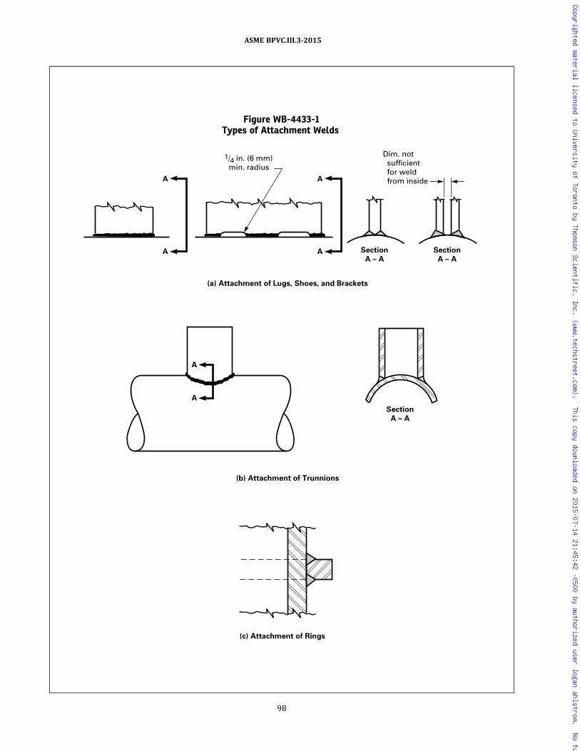
Figure WB-4433-1Types of Attachment Welds
(c) Attachment of Rings
(a) Attachment of Lugs, Shoes, and Brackets
(b) Attachment of Trunnions
1/4 in. (6 mm) min. radius
Dim. not sufficient for weld from inside
A
A
A
A
A
A Section
A – A
Section
A – A
Section
A – A
98
ASME BPVC.III.3-2015
Copyrighted material licensed to University of Toronto by Thomson Scientific, Inc. (www.techstreet.com). This copy downloaded on 2015-07-14 21:45:42 -0500 by authorized user logan ahlstrom. No further reproduction or distribution is permitted.

(b)When repairs to welds joining P‐No. 1 and P‐No. 3materials require examination by radiography as re-quired in (a) above, but construction assembly preventsmeaningful radiographic examination, ultrasonic exami-nation may be substituted provided:
(1) the weld had been previously radiographed andmet the applicable acceptance standards;
(2) the ultrasonic examination is performed using aprocedure in accordance with Section V, Article 4, to theacceptance standards of WB-5330;
(3) the substitution is limited to Category A and Bwelds in containments, and similar type welds in otheritems.
The absence of suitable radiographic equipment isnot justification for the substitution.
WB-4453.5 Heat Treatment of Repaired Areas. Thearea shall be heat-treated in accordance with WB-4620.
WB-4600 HEAT TREATMENT
WB-4610 WELDING PREHEAT REQUIREMENTSWB-4611 When Preheat Is Necessary
The need for and temperature of preheat are depen-dent on a number of factors, such as the chemical analysis,degree of restraint of the parts being joined, elevated tem-perature, physical properties, and material thicknesses.Some practices used for preheating are given in SectionIII Appendices, Nonmandatory Appendix D as a generalguide for the materials listed by P‐Numbers of SectionIX. It is cautioned that the preheating suggested in SectionIII Appendices, Nonmandatory Appendix D does not ne-cessarily ensure satisfactory completion of the weldedjoint and that the preheating requirements for individualmaterials within the P‐Number may be more or less re-strictive. The Welding Procedure Specification for the ma-terial being welded shall specify the minimum preheatingrequirements under the welding procedure qualificationrequirements of Section IX.
WB-4612 Preheating Methods
Preheat for welding or thermal cutting, when em-ployed, may be applied by any method which does notharm the base material or any weld metal already applied,or which does not introduce deleterious material into thewelding area which is harmful to the weld.
WB-4613 Interpass Temperature
Consideration shall be given to the limitations of inter-pass temperatures for quenched and tempered materialto avoid detrimental effects on the mechanical properties.
WB-4620 POSTWELD HEAT TREATMENTWB-4621 Heating and Cooling Methods
Postweld heat treatment (PWHT) may be accomplishedby any suitable methods of heating and cooling, providedthe required heating and cooling rates, metal tempera-ture, metal temperature uniformity, and temperaturecontrol are maintained.
WB-4622 PWHT Time and TemperatureRequirements
WB-4622.1 General Requirements.8 Except as other-wise permitted in WB-4622.7, all welds, including repairwelds, shall be postweld heat-treated. During postweldheat treatment, the metal temperature shall be main-tained within the temperature range and for the mini-mum holding time specified in Table WB-4622.1-1,except as otherwise permitted in WB-4622.4(c).P‐Number groups in Table WB-4622.1-1 are in accor-dance with Section IX, QW-420. Except as provided inWB-4624.3, PWHT shall be performed in temperature‐surveyed and ‐calibrated furnaces, or PWHT shall be per-formed with thermocouples in contact with the materialor attached to blocks in contact with the material. In ad-dition, the requirements of the following subparagraphsshall apply.
WB-4622.2 Time–Temperature Recordings. Time–temperature recordings of all postweld heat treatmentsshall be made available for review by the Inspector. Iden-tification on the time–temperature recording shall be tothe weld or containment, as applicable. A summary ofthe time–temperature recording may be provided for per-manent records in accordance with WA-4134.
WB-4622.3 Definition of Nominal Thickness Gov-e r n i n g P W H T . Nom i n a l t h i c k n e s s i n T a b l eWB-4622.7(b)-1 is the thickness of the weld, the contain-ment material for structural attachment welds or thethinner of the containment materials being joined, which-ever is least. It is not intended that nominal thickness in-clude material provided for forming allowance, thinning,or mill overrun when the excess material does not exceed1/8 in. (3 mm). For fillet welds the nominal thickness is thethroat thickness, and for partial penetration and materialrepair welds the nominal thickness is the depth of theweld groove or preparation.
WB-4622.4 Holding Times at Temperature.(a) The holding time at temperature as specified in
Table WB-4622.1-1 shall be based on the nominal thick-ness of the weld. The holding time need not be continu-ous. It may be an accumulation of the times of multiplepostweld heat treat cycles.
(b) Holding time at temperature in excess of the mini-mum requirements of Table WB-4622.1-1 may be used,provided that specimens so heat-treated are tested in ac-cordance with WB-2200, WB-2400, and WB-4300.
99
ASME BPVC.III.3-2015
Copyrighted material licensed to University of Toronto by Thomson Scientific, Inc. (www.techstreet.com). This copy downloaded on 2015-07-14 21:45:42 -0500 by authorized user logan ahlstrom. No further reproduction or distribution is permitted.

(c) Alternatively, when it is impractical to postweldheat treat at the temperature range specified in TableWB-4622.1-1, it is permissible to perform the postweldheat treatment of certain materials at lower temperaturesfor longer periods of time in accordance with TableWB-4622.4(c)-1 and (1), (2), and (3) below.
(1) Except for P‐No. 1 materials, when welds in thematerials listed in Table WB-4622.4(c)-1 are to be post-weld heat-treated at the lower minimum temperatures,the impact test specimens for the welding procedure qua-lification required by WB-4300 shall be made using thesame minimum temperatures and increased minimumholding time. Welding procedures, qualified at the tem-perature range and minimum holding time specified inTable WB-4622.1-1 and at the lower temperature and in-creased minimum holding time permitted by TableWB-4622.4(c)-1, are also qualified for any temperaturein between. When such an in‐between temperature isused, the minimum holding time shall be interpolatedfrom Table WB-4622.1-1 and the alternative require-ments from Table WB-4622.4(c)-1.
(2) Except for P‐No. 1 materials, when welds in thematerials listed in Table WB-4622.4(c)-1 are to be post-weld heat-treated at these lower minimum temperatures,the welding material certification required by WB-2400shall be made using the same minimum temperatureand increased minimum holding time. Welding materialcertified at the temperature range and minimum holdingtime specified in Table WB-4622.1-1 and at the lowerminimum temperatures and increased minimum holdingtime permitted by Table WB-4622.4(c)-1 are also certi-fied for any temperature in between.
(3) Base material certified in accordance withWB-2200 may be postweld heat-treated at the lowerminimum temperature ranges and increased minimumholding times without recertification. Postweld heattreatment at these lower minimum temperatures and in-creased minimum holding times may also be the temper-ing operation provided a higher tempering temperature isnot required by the material specification.
WB-4622.5 PWHT Requirements When DifferentP-Number Materials Are Joined. When materials of twodifferent P‐Number groups are joined by welding, the ap-plicable postweld heat treatment shall be that specified inTable WB-4622.1-1 for the material requiring the higherPWHT temperature range.
WB-4622.6 PWHT Requirements for Noncontain-ment Parts. When noncontainment material is weldedto containment material, the postweld heat treatmenttemperature range of the containment material shallcontrol.
WB-4622.7 Exemptions to Mandatory Require-ments. Postweld heat treatment in accordance with thissubarticle is not required for:(a) nonferrous material;
Table WB-4622.1-1Mandatory Requirements for Postweld Heat Treatment of Welds
P‐No. (Sec. IX, QW-420)
HoldingTemperatureRange, °F (°C)
[Note (1)]
Minimum Holding Time at Temperature for Weld Thickness (Nominal)
1/2 in. (13 mm)or less
Over 1/2 in. to 2 in.(13 mm to 50 mm)
Over 2 in. to 5 in.(50 mm to 125 mm) Over 5 in. (125 mm)
1, 3 1,100–1,250(595–675)
30 min 1 hr/in. (2 min/mm) 2 hr plus 15 min eachadditional inch (2 hplus 0.5 min/mm)over 2 in. (50 mm)
2 hr plus 15 min eachadditional inch (2 hplus 0.5 min/mm)over 2 in. (50 mm)
P‐Nos. 8, 10 H Gr. 1, 34, 42,43, 45 and hard surfacingon P‐No. 1 base metalwhose reported carboncontent is not more than0.30%
PWHT neither required nor prohibited
GENERAL NOTE: Exemptions to the mandatory requirements of this Table are defined in WB-4622.7.
NOTE:(1) All temperatures are metal temperatures.
Table WB-4622.4(c)-1Alternative Holding Temperatures and Times
MaterialP‐No.
Alternative MinimumHolding Temperatures,
°F (°C)Alternative Minimum
Holding Times [Note (1)]
1, 3 1,050 (565) 2 hr/in. (4 min/mm) thick1, 3 1,000 (540) 4 hr/in. (8 min/mm) thick
NOTE:(1) All other requirements of WB-4622 shall apply.
100
ASME BPVC.III.3-2015
Copyrighted material licensed to University of Toronto by Thomson Scientific, Inc. (www.techstreet.com). This copy downloaded on 2015-07-14 21:45:42 -0500 by authorized user logan ahlstrom. No further reproduction or distribution is permitted.
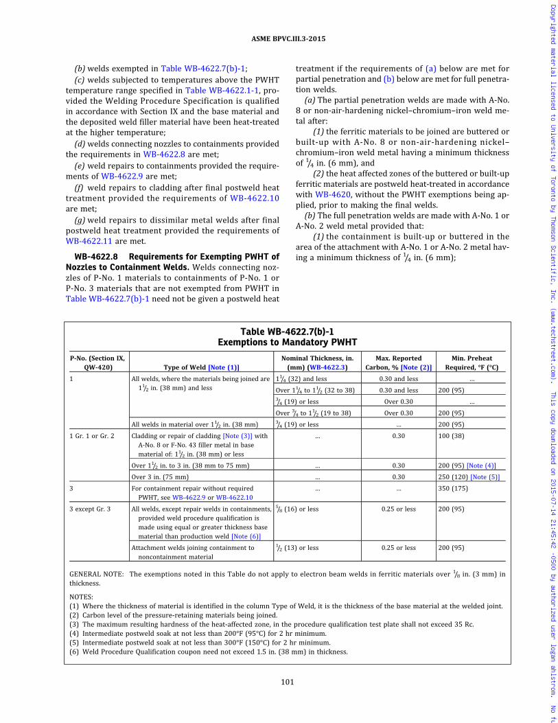
(b) welds exempted in Table WB-4622.7(b)-1;(c) welds subjected to temperatures above the PWHT
temperature range specified in Table WB-4622.1-1, pro-vided the Welding Procedure Specification is qualifiedin accordance with Section IX and the base material andthe deposited weld filler material have been heat-treatedat the higher temperature;
(d) welds connecting nozzles to containments providedthe requirements in WB-4622.8 are met;
(e) weld repairs to containments provided the require-ments of WB-4622.9 are met;
(f) weld repairs to cladding after final postweld heattreatment provided the requirements of WB-4622.10are met;
(g) weld repairs to dissimilar metal welds after finalpostweld heat treatment provided the requirements ofWB-4622.11 are met.
WB-4622.8 Requirements for Exempting PWHT ofNozzles to Containment Welds. Welds connecting noz-zles of P‐No. 1 materials to containments of P‐No. 1 orP‐No. 3 materials that are not exempted from PWHT inTable WB-4622.7(b)-1 need not be given a postweld heat
treatment if the requirements of (a) below are met forpartial penetration and (b) below are met for full penetra-tion welds.
(a) The partial penetration welds are made with A‐No.8 or non‐air‐hardening nickel–chromium–iron weld me-tal after:
(1) the ferritic materials to be joined are buttered orbuilt‐up with A‐No. 8 or non‐air‐hardening nickel–chromium–iron weld metal having a minimum thicknessof 1/4 in. (6 mm), and
(2) the heat affected zones of the buttered or built‐upferritic materials are postweld heat-treated in accordancewith WB-4620, without the PWHT exemptions being ap-plied, prior to making the final welds.
(b) The full penetration welds are made with A‐No. 1 orA‐No. 2 weld metal provided that:
(1) the containment is built‐up or buttered in thearea of the attachment with A‐No. 1 or A‐No. 2 metal hav-ing a minimum thickness of 1/4 in. (6 mm);
Table WB-4622.7(b)-1Exemptions to Mandatory PWHT
P‐No. (Section IX,QW‐420) Type of Weld [Note (1)]
Nominal Thickness, in.(mm) (WB-4622.3)
Max. ReportedCarbon, % [Note (2)]
Min. PreheatRequired, °F (°C)
1 All welds, where the materials being joined are11/2 in. (38 mm) and less
11/4 (32) and less 0.30 and less …
Over 11/4 to 11/2 (32 to 38) 0.30 and less 200 (95)3/4 (19) or less Over 0.30 …
Over 3/4 to 11/2 (19 to 38) Over 0.30 200 (95)
All welds in material over 11/2 in. (38 mm) 3/4 (19) or less … 200 (95)
1 Gr. 1 or Gr. 2 Cladding or repair of cladding [Note (3)] withA‐No. 8 or F‐No. 43 filler metal in basematerial of: 11/2 in. (38 mm) or less
… 0.30 100 (38)
Over 11/2 in. to 3 in. (38 mm to 75 mm) … 0.30 200 (95) [Note (4)]
Over 3 in. (75 mm) … 0.30 250 (120) [Note (5)]
3 For containment repair without requiredPWHT, see WB-4622.9 or WB-4622.10
… … 350 (175)
3 except Gr. 3 All welds, except repair welds in containments,provided weld procedure qualification ismade using equal or greater thickness basematerial than production weld [Note (6)]
5/8 (16) or less 0.25 or less 200 (95)
Attachment welds joining containment tononcontainment material
1/2 (13) or less 0.25 or less 200 (95)
GENERAL NOTE: The exemptions noted in this Table do not apply to electron beam welds in ferritic materials over 1/8 in. (3 mm) inthickness.
NOTES:(1) Where the thickness of material is identified in the column Type of Weld, it is the thickness of the base material at the welded joint.(2) Carbon level of the pressure-retaining materials being joined.(3) The maximum resulting hardness of the heat-affected zone, in the procedure qualification test plate shall not exceed 35 Rc.(4) Intermediate postweld soak at not less than 200°F (95°C) for 2 hr minimum.(5) Intermediate postweld soak at not less than 300°F (150°C) for 2 hr minimum.(6) Weld Procedure Qualification coupon need not exceed 1.5 in. (38 mm) in thickness.
101
ASME BPVC.III.3-2015
Copyrighted material licensed to University of Toronto by Thomson Scientific, Inc. (www.techstreet.com). This copy downloaded on 2015-07-14 21:45:42 -0500 by authorized user logan ahlstrom. No further reproduction or distribution is permitted.

(2) the A‐No. 1 or A‐No. 2 weld metal buildup or but-tering is postweld heat-treated in accordance withWB-4620 for P‐No. 1 or P‐No. 3 materials without thePWHT exemptions being applied;
(3) the welds do not penetrate through the contain-ment thickness;
(4)weld metal with A‐No. 1 or A‐No. 2 analysis isused to join the nozzle of P‐No. 1 material to the weldbuildup or buttering;
(5) the nominal thickness of the weld joining the noz-zle to the containment does not exceed 11/2 in. (38 mm)and the maximum reported carbon content of the nozzledoes not exceed 0.30%;
(6) a 200°F (95°C) minimum preheat is maintainedduring welding whenever the nominal thickness of theweld exceeds:
(-a) 11/4 in. (32 mm) and the maximum reportedcarbon content of the material of the nozzle is 0.30% orless, or
(-b) 3/4 in. (19 mm) and the maximum reportedcarbon content of material of the nozzle exceeds 0.30%.
WB-4622.9 Temper Bead Weld Repair. Limited weldrepairs to P‐No. 1 and P‐No. 3 material, and A‐Nos. 1, 2,10, or 11 weld filler metal (Section IX, Table QW-442),may be made without PWHT or after the final PWHT, pro-vided it is impossible or impractical to postweld heattreat the area after repair, and provided the requirementsof the following subparagraphs are met:
(a) Examination of Area to Be Repaired. Before repair,the area shall be examined by either the magnetic particleor liquid penetrant method in accordance with ArticleWB-5000.
(b) Maximum Extent of Repair. The maximum area of anindividual repair based on the finished surface shall be100 in.2 (65 000 mm2) and the depth of repair shall notbe greater than one‐third of the base material thickness.
(c) Repair Welding Procedure. The welding procedureshall be in accordance with Section IX and this Subsectionand shall include the requirements of (1) through (6)below.
(1) The area to be repaired shall be suitably preparedfor welding in accordance with a written procedure.
(2) The weld metal shall be deposited by the manualshielded metal arc process using low hydrogen type elec-trode. The maximum bead width shall be four times theelectrode core diameter.
(3)Welding electrodes shall meet the requirementsfor supplemental des ignators “R ” indicat ing amoisture-resistant coating and “H4” indicating that theyare low in diffusible hydrogen as defined in the applicablespecifications in Section II, Part C. Welding electrodesshall also be supplied in unopened hermetically sealedcontainers.
(4) After a hermetically sealed container is opened,the electrodes shall be stored in holding ovens at 225°Fto 350°F (105°C to 175°C). When electrodes are removedfrom elevated storage, they may be exposed to the atmo-sphere for a maximum of 8 hr.
(5) Electrodes, which are exposed to the atmospherefor more than 8 hr, shall be discarded or baked to removeany absorbed moisture for the time and temperature rec-ommended by the electrode manufacturer. After bakingand before the electrodes are allowed to cool below225°F (105°C), they shall be transferred immediately intoholding ovens at 225°F to 350°F (105°C to 175°C). Whenthe once-baked electrodes are removed from elevatedstorage, they may be exposed to the atmosphere for anadditional 8 hr after which they shall be discarded.
(6) If the repair area is to be subjected to a significantfast neutron fluence (greater than 1019 nvt Eo >1 MeV),electrode shall be limited to Cu content of 0.10% maxi-mum (as deposited).
(7) The weld area plus a band around the repair areaof at least 11/2 times the component thickness or 5 in.(125mm), whichever is less, shall be preheated andmain-tained at a minimum temperature of 350°F (175°C) dur-ing welding. The maximum interpass temperature shallbe 450°F (230°C). Thermocouples and recording instru-ments shall be used to monitor the process temperatures.Their removal shall be in accordance with WB-4435(b).
(8) The cavity shall be buttered, using a 3/32 in.(2.5 mm) diameter electrode as shown in FigureWB-4622.9(c)(8)-1. The weld bead crown surface shallbe removed by grinding or machining before depositingthe second layer [see Figure WB-4622.9(c)(8)-1, Step 2].The second layer shall be deposited with a 1/8 in.(3 mm) diameter electrode. Subsequent layers shall bedeposited with a welding electrode no larger than5/32 in. (4 mm) diameter. Bead deposition shall be per-f o r m e d i n a m a n n e r s h o w n i n F i g u r eWB-4622.9(c)(8)-1, Step 3. The completed weld shallhave at least one layer of weld reinforcement depositedand then this reinforcement shall be removed by mechan-ical means, making the finished surface of the repair sub-stantially flush with the surface of the containmentsurrounding the repair [Figure WB-4622.9(c)(8)-2]. Thetechnique described in this paragraph shall be performedin the procedure qualification test.
(9) The weld area shall be maintained at a tempera-ture of 450°F to 550°F (230°C to 290°C) for a minimumperiod of 2 hr after completion of the weld repair inP‐No. 1 materials. For P‐No. 3 materials, the holding timeshall be a minimum of 4 hr.(d) Examination of Repair Welds. The second (temper
bead) layer shall be examined by the magnetic particleor liquid penetrant method. The completed weld shallhave the weld reinforcement, including the final layer, re-moved substantially flush with the surface prior to per-forming the required nondestructive examination. Thenondestructive examination shall be performed after the
102
ASME BPVC.III.3-2015
Copyrighted material licensed to University of Toronto by Thomson Scientific, Inc. (www.techstreet.com). This copy downloaded on 2015-07-14 21:45:42 -0500 by authorized user logan ahlstrom. No further reproduction or distribution is permitted.

Figure WB-4622.9(c)(8)-1Temper Bead Weld Repair and Weld Temper Bead Reinforcement
Reinforcement weld
Temper bead layer
Step 3:
Step 2: Remove the weld bead crown of the first layer of grinding.
Step 1: Butter cavity with one layer of weld metal using 3/32 in. (2.5 mm) diameter coated electrode.
The second layer shall be deposited with a 1/8 in. (3 mm) diameter electrode. Subsequent layers shall be deposited with welding electrodes no larger than 5/32 in. (4.0 mm) maximum diameter. Bead deposition shall be performed in the manner as shown. Particular care shall be taken in the application of the temper bead reinforcement weld at the tie-in points as well as its removal to ensure that the heat-affected zone of the base metal and the deposited weld metal is tempered and the resulting surface is substantially flush.
103
ASME BPVC.III.3-2015
Copyrighted material licensed to University of Toronto by Thomson Scientific, Inc. (www.techstreet.com). This copy downloaded on 2015-07-14 21:45:42 -0500 by authorized user logan ahlstrom. No further reproduction or distribution is permitted.

completed weld has been at ambient temperature for aminimum period of 48 hr to detect the presence of possi-ble delayed cracking of the weldment. The nondestructiveexamination of the repair welded and preheated regionshall be in accordance with WB-4453.4. In addition, all re-pairs shall be ultrasonically examined. All nondestructiveexamination shall be in accordance with Article WB-5000.
(e) Documentation of Weld Repairs. Documentation ofweld repairs shall be in accordance with WB-4130, exclu-sive of the size requirements.
(f) Welding Procedure Qualification Test Plate. The testassembly materials for the welding procedure qualifica-tion shall be of the same P‐Number and Group Number,including a postweld heat treatment that is at leastequivalent to the time and temperature applied to the ma-terials being repaired. The depth of cavity in the test as-sembly shall be a minimum of one‐half the depth ofactual repair, but not less than 1 in. (25 mm). The test as-sembly thickness shall be a minimum of twice the depthof cavity in the test assembly. The test assembly shallbe large enough to permit removal of the required testspecimens. In order to simulate the restraint that theweld metal will experience in the repair section of thecomponent, the test assembly dimensions surroundingthe cavity shall be equal to the test assembly thickness,but not less than 6 in. (150 mm). The qualification testplate shall be prepared in accordance with FigureWB-4622.9(f)-1.
(g) This test assembly may be used to qualify proce-dures for weld buildup repairs of pressure-retaining ma-terials. In this case, the depth of the cavity shall not be lessthan the thickness of the weld buildup or 1 in. (25 mm),whichever is greater, and the area of the weld buildupto be applied or 54 in.2 (35 000 mm2), whichever is less.
(h) In all cases, the test assembly and cavity shall be ofsufficient size to permit removal of the required testspecimens.
(i) Performance Qualifications. If the repair weld is tobe performed where physical obstructions impair thewelder ’s ability to perform, the welder shall also
demonstrate the ability to deposit sound weld metal inthe positions required, using the same parameters and si-mulated physical obstructions as are involved in therepair.
WB-4622.10 Repair Welds to Cladding After FinalPostweld Heat Treatment. Nonpostweld heat-treatedweld repairs may be made to P‐No. 8 or P‐No. 43 claddingof P‐No. 1 and P‐No. 3 material after final PWHT, providedit is impossible or impractical to postweld heat treat thearea after repair, and provided the requirements of thefollowing subparagraphs are met:
(a) Maximum Extent of Repair. This procedure may beused with the base material exposed to a depth not great-er than 1/4 in. (6 mm) or 10% of the base material thick-ness, whichever is less, nor to an individual area greaterthan 100 in.2 (65 000 mm2). Areas with greater base ma-terial exposure depth shall be repaired in accordancewith WB-4622.9 to within this limit before implementingthe cladding repair.
(b) Repair Welding Procedure. The welding procedureshall be in accordance with Section IX and this Division,and shall include the requirements of (1) through (7)below.
(1) The repairs shall be made using A‐No. 8 weld me-tal (Section IX, Table QW-442) for P‐No. 8 cladding orF‐No. 43 weld metal (Section IX, Table QW-432) for eitherP‐No. 8 or P‐No. 43 cladding.
(2) The manual shielded metal arc process shall beused for welding with a bead width not to exceed fourtimes the electrode core diameter.
(3) All covered electrodes used for qualification testand repair welding shall be from unopened, hermeticallysealed packages or heated ovens maintained between225°F (105°C) and 350°F (175°C). Electrodes withdrawnfrom hermetically sealed containers or ovens for longerthan 8 hr shall be discarded, or baked once at the timeand temperature recommended by the electrode manu-facturer and placed immediately back into the holdingovens. Electrodes exposed to the atmosphere for morethan 8 hr after once being baked shall be discarded.
(4) During the repair, the electrodes may be main-tained in heated ovens in the repair area. The oven tem-perature shall be maintained between 225°F (105°C)and 350°F (175°C). Electrodes exposed to the atmospherefor more than 8 hr shall be discarded, or baked once atthe time and temperature recommended by the electrodemanufacturer and placed immediately back into the hold-ing ovens. Electrodes exposed to the atmosphere for morethan 8 hr after once being baked shall be discarded.
(5) The weld area plus a band around the clad repairof 11/2 times the component thickness or 5 in. (125 mm),whichever is less, shall be preheated and maintained at aminimum temperature of 350°F (175°C) during welding.The maximum interpass temperature shall be 450°F
Figure WB-4622.9(c)(8)-2Temper Bead Reinforcement
NOTE:(1) Apply temper bead reinforcement weld metal to a level above
the surface and then remove it substantially flush to the surfaceas required by WB-4622.9(c)(8).
104
ASME BPVC.III.3-2015
Copyrighted material licensed to University of Toronto by Thomson Scientific, Inc. (www.techstreet.com). This copy downloaded on 2015-07-14 21:45:42 -0500 by authorized user logan ahlstrom. No further reproduction or distribution is permitted.

Figure WB-4622.9(f)-1Qualification Test Plate
Reduced section
Side bend
Side bend
Reduced section
Side bend
Side bend
Discard
specimen
specimen
specimen
specimen
specimen
specimen
Charpy
Charpy
Charpy
V – Notch (HAZ)
V – Notch (HAZ)
Charpy V – Notch (HAZ)
1/8 in. 1/32 in. (3 mm 0.8 mm)Fusion line
30 deg (max.)
Weld metal
Heat-affected zone
3/8 in. (10 mm)WB-4622.9(f)Elevation
view
Plan
view
1/2 in. (13 mm) min.
V – Notch (HAZ)
105
ASME BPVC.III.3-2015
Copyrighted material licensed to University of Toronto by Thomson Scientific, Inc. (www.techstreet.com). This copy downloaded on 2015-07-14 21:45:42 -0500 by authorized user logan ahlstrom. No further reproduction or distribution is permitted.

(230°C). Thermocouples and recording instruments shallbe used to monitor the process temperatures. Their re-moval shall be in accordance with WB-4435.
(6) All areas of the base material on which weld me-tal is to be deposited shall be covered with a single layerof weld deposit using 3/32 in. (2.5 mm) diameter electrode,followed by a minimum of one layer of weld deposit using1/8 in. (3 mm) diameter electrode. Subsequent layers maybe deposited with electrode no larger than 5/32 in. (4 mm).The weld bead crown surface of the first layer shall be re-moved by grinding.
(7) After completion of welding, the weld area shallbe maintained at a temperature of 450°F to 550°F(230°C to 290°C) for a period of 2 hr for P‐No. 1 materialand 4 hr for P‐No. 3 material.
(c) Examination of Repair Welds. The weld repair aswell as the preheated band shall be examined by the li-quid penetrant method. All nondestructive examinationshall be in accordance with Article WB-5000.
(d) Documentation of Weld Repairs. Documentation ofweld repairs shall be in accordance with WB-4130, exclu-sive of the size requirements.
(e) Welding Procedure Qualification Test Plate
(1) The test assembly material for the welding proce-dure qualification test shall be of the same P‐Number andGroup Number, including a postweld heat treatment thatis at least equivalent to the time and temperature of thatapplied to the material being repaired. If the repair in-volves two different P‐Number or Group Number materi-als, the test assembly shall duplicate the combination.
(2) The test assembly base material shall be at least12 in. (300 mm) by 12 in. (300 mm), 2 in. (50 mm)min. thickness, with a clad surface area of at least 8 in.(200 mm) by 8 in. (200 mm), in the area from whichthe bend test specimens will be removed.
(3) The qualification test plate assembly shall be pre-pared and tested in accordance with the requirements ofSection IX. The guided bend test acceptance standards de-scribed in Section IX for cladding shall also be applicableto the HAZ of the base material.
(f) Performance Qualifications. If the repair weld is tobe performed where physical obstructions impair thewelder’s ability to perform, the welder shall also demon-strate the ability to deposit sound weld metal in the posi-tions required, using the same parameters and simulatedphysical obstructions as are involved in the repair.
WB-4622.11 Temper Bead Weld Repair to DissimilarMetal Welds or Buttering. Whenever PWHT is impracti-cal or impossible, limited weld repairs to dissimilar metalwelds of P‐No. 1 and P‐No. 3 material or weld filler metalA‐No. 8 (Section IX, Table QW-442) or F‐No. 43 (SectionIX, Table QW-432) may be made without PWHT or afterthe final PWHT provided the requirements of the follow-ing subparagraphs are met:
(a) Examination of Area to Be Repaired. Before repair,the area shall be examined by either the magnetic particleor liquid penetrant method in accordance with ArticleWB-5000.
(b) Maximum Extent of Repair. Repairs made to thisparagraph are limited to those along the fusion line of anonferritic weld to ferritic base material where 1/8 in.(3 mm) or less of nonferritic weld deposit exists abovethe original fusion line after defect removal. If the defectpenetrates into the ferritic base material, repair of thebase material may be performed in accordance withWB-4622.11 provided the depth of repair in the base ma-terial does not exceed 3/8 in. (10 mm). The repairs to acompleted joint shall not exceed one‐half the joint thick-ness. The surface of the completed repair shall not exceed100 in.2 (65 000 mm2).
(c) Repair Welding Procedure. The welding procedureand welder qualification shall meet all of the require-ments of Section IX and the additional requirements ofthis Article. In addition, the Welding Procedure Specifica-tion shall include the following requirements.
(1) The area to be repaired shall be suitably preparedfor welding in accordance with the written procedure tobe used for the repair.
(2) The weld metal shall be deposited by the shieldedmetal arc welding process (SMAW) using A‐No. 8 weldmetal (Section IX, Table QW-442) for P‐No. 8 to P‐No. 1or P‐No. 3 weld joints or F‐No. 43 weld metal (SectionIX, Table QW-432) for either P‐No. 8 or P‐No. 43 toP‐No. 1 or P‐No. 3 weld joints. The maximum bead widthshall be four times the electrode core diameter.
(3) All covered electrodes used for qualification testand repair welding shall be from unopened, hermeticallysealed packages or heated ovens maintained between225°F (105°C) and 350°F (175°C). Electrodes withdrawnfrom hermetically sealed containers or ovens for longerthan 8 hr shall be discarded, or baked once at the timeand temperature recommended by the electrode manu-facturer and placed immediately back into the holdingovens. Electrodes exposed to the atmosphere for morethan 8 hr after once being baked shall be discarded.
(4) During the repair, the electrode may be main-tained in heated ovens in the repair area. The oven tem-perature shall be maintained between 225°F (105°C)and 350°F (175°C). Electrodes exposed to the atmospherefor more than 8 hr shall be discarded, or baked once atthe time and temperature recommended by the electrodemanufacturer and placed immediately back into the hold-ing ovens. Electrodes exposed to the atmosphere for morethan 8 hr after once being baked shall be discarded.
(5) The weld area plus a band around the weld repairof 11/2 times the component thickness or 5 in. (125 mm),whichever is less, shall be preheated and maintained at aminimum temperature of 350°F (175°C) during welding.The maximum interpass temperature shall be 450°F
106
ASME BPVC.III.3-2015
Copyrighted material licensed to University of Toronto by Thomson Scientific, Inc. (www.techstreet.com). This copy downloaded on 2015-07-14 21:45:42 -0500 by authorized user logan ahlstrom. No further reproduction or distribution is permitted.
(230°C). Thermocouples and recording instruments shallbe used to monitor the metal temperature during weld-ing. Their removal shall be in accordance with WB-4435.
(6) All areas of the ferritic base material, exposed ornot, on which weld metal is to be deposited, shall be cov-ered with a single layer of weld deposit using 3/32 in.(2.5 mm) diameter electrode. The weld bead crown sur-face shall be removed by grinding before depositing thesecond layer. The second layer shall be deposited with1/8 in. (3 mm) diameter electrode. Subsequent layersmay be deposited with 5/32 in. (4 mm)maximum diameterelectrode. The techniques described in this paragraphshall be duplicated in the procedure qualification. [SeeFigure WB-4622.11(c)(6)-1.]
(7) After at least 3/16 in. (5 mm) of weld metal hasbeen deposited, the preheated area as defined in (5)above shall be maintained in the range of 450°Fto 550°F (230°C to 290°C) for 4 hr as a minimum.
(8) Subsequent to the above heat treatment, the bal-ance of the welding may be performed at a minimum pre-heat temperature of 100°F (40°C) and at a maximuminterpass temperature of 350°F (175°C).
(d) Examination of Repair Areas(1) After the heat treatment specified in (c)(7) above
has been completed, the repaired area shall be examinedby the liquid penetrant method.
(2) The repaired area and the preheated band as de-fined in (c)(5) above shall be examined by the liquid pe-netrant method after the completed weld has been atambient temperature for a minimum of 48 hr. The re-paired region shall be examined by the radiographicmethod and, if practical, by the ultrasonic method.
(3) For repairs to partial penetration welds, theradiographic and ultrasonic examinations specified in(2) above need not be performed, if meaningful resultscannot be obtained. For these cases, liquid penetrant ex-amination only shall be performed. For weld repairdepths approximately 3/16 in. (5 mm), liquid penetrant ex-amination shall be performed at the time specified in (2)above. For weld repair depths greater than 3/16 in.(5 mm), liquid penetrant examination shall be performedafter approximately 3/16 in. (5 mm) thickness has been de-posited and the post heat specified in (c)(7) above hasbeen completed. Additional incremental deposit thick-nesses shall be liquid penetrant examined in accordancewith WB-5245. The final weld surface shall be liquid pe-netrant examined at the time specified in (2) above.
(4) All nondestructive examination shall be in accor-dance with Article WB-5000.
(e) Documentation of Weld Repairs. Documentation ofweld repairs shall be in accordance with WB-4130, exclu-sive of the size requirements.
(f) Welding Procedure Qualification Test Plate. The testassembly materials for the welding procedure qualifica-tion shall be of the same P‐Number and Group Number,including a postweld heat treatment that is at leastequivalent to the time and temperature applied to the
materials being repaired. The depth of cavity in the testassembly shall be a minimum of one‐half the depth of ac-tual repair but not less than 1 in. (25 mm). The test as-sembly thickness shall be a minimum of twice the depthof cavity in the test assembly. The test assembly shallbe large enough to permit removal of the required testspecimens. In order to simulate the restraint that theweld metal will experience in the repaired section ofthe component, the test assembly dimensions surround-ing the cavity shall be equal to the test assembly thick-ness, but not less than 6 in. (150 mm). The qualificationtest plate shall be prepared in accordance with FigureWB-4622.9(f)-1.
(g) Performance Qualifications. If the repair weld is tobe performed where physical constructions impair thewelder’s ability to perform, the welder shall also demon-strate the ability to deposit sound weld metal in the posi-tions required, using the same parameters and simulatedphysical obstructions as are involved in the repair.
WB-4623 PWHT Heating and Cooling RateRequirements
Above 800°F (425°C) the rate of heating and cooling inany hourly interval shall not exceed 400°F (220°C) di-vided by the maximum thickness in inches of the materialbeing heat-treated, but shall not exceed 400°F (220°C)and need not be less than 100°F (55°C) in any hourly in-terval. During the heating and cooling period there shallnot be a greater variation in temperature than 250°F(140°C) within any 15 ft (4.5 m) interval of weld length.
WB-4624 Methods of Postweld Heat TreatmentThe postweld heat treatment shall be performed in ac-
cordance with the requirements of one of the followingsubparagraphs.
WB-4624.1 Furnace Heating — One Heat. Heatingthe item in a closed furnace in one heat is the preferredprocedure and should be used whenever practical. Thefurnace atmosphere shall be controlled so as to avoid ex-cessive oxidation and direct impingement of flame on thecontainment is prohibited.
WB-4624.2 Furnace Heating — More Than OneHeat. The item may be heated in more than one heat ina furnace, provided the furnace atmosphere control re-quirements of WB-4624.1 apply and overlap of the heatedsections of the component or item is at least 5 ft (1.5 m).When this procedure is used, the portion of the compo-nent or item outside the furnace shall be shielded so thatthe temperature gradient is not harmful. The cross sec-tion where the containment projects from the furnaceshall not intersect a nozzle or other structuraldiscontinuity.
WB-4624.3 Local Heating. Welds may be locallypostweld heat-treated when it is not practical to heattreat the entire component or item. Local postweld heattreatment shall consist of heating a circumferential band
107
ASME BPVC.III.3-2015
Copyrighted material licensed to University of Toronto by Thomson Scientific, Inc. (www.techstreet.com). This copy downloaded on 2015-07-14 21:45:42 -0500 by authorized user logan ahlstrom. No further reproduction or distribution is permitted.
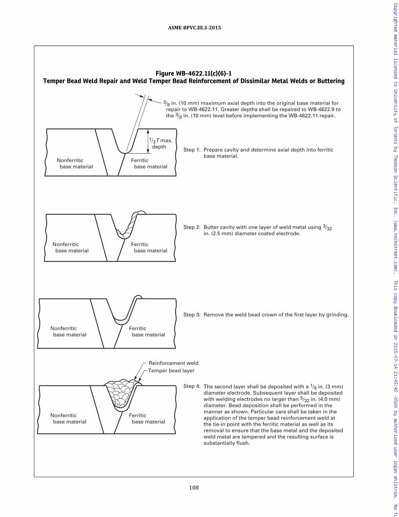
Figure WB-4622.11(c)(6)-1Temper Bead Weld Repair and Weld Temper Bead Reinforcement of Dissimilar Metal Welds or Buttering
1/2T max. depth
Reinforcement weldTemper bead layer
Ferritic base material
Nonferritic base material
Ferritic base material
Nonferritic base material
Ferritic base material
Nonferritic base material
Ferritic base material
3/8 in. (10 mm) maximum axial depth into the original base material for repair to WB-4622.11. Greater depths shall be repaired to WB-4622.9 to the 3/8 in. (10 mm) level before implementing the WB-4622.11 repair.
Nonferritic base material
Step 4:
Step 3: Remove the weld bead crown of the first layer by grinding.
Step 2: Butter cavity with one layer of weld metal using 3/32in. (2.5 mm) diameter coated electrode.
Step 1: Prepare cavity and determine axial depth into ferritic base material.
The second layer shall be deposited with a 1/8 in. (3 mm) diameter electrode. Subsequent layer shall be deposited with welding electrodes no larger than 5/32 in. (4.0 mm) diameter. Bead deposition shall be performed in the manner as shown. Particular care shall be taken in the application of the temper bead reinforcement weld at the tie-in point with the ferritic material as well as its removal to ensure that the base metal and the deposited weld metal are tempered and the resulting surface is substantially flush.
108
ASME BPVC.III.3-2015
Copyrighted material licensed to University of Toronto by Thomson Scientific, Inc. (www.techstreet.com). This copy downloaded on 2015-07-14 21:45:42 -0500 by authorized user logan ahlstrom. No further reproduction or distribution is permitted.

around the containment at temperature within the rangesspecified in this subarticle. The minimum width of thecontrolled band at each side of the weld, on the face ofthe greatest weld width, shall be the thickness of the weldor 2 in. (50 mm), whichever is less. The temperature ofthe component or item from the edge of the controlledband outward shall be gradually diminished so as to avoidharmful thermal gradients. This procedure may also beused for postweld heat treatment after repairs.
WB-4624.4 Heating Items Internally. The contain-ment may be heated internally by any appropriate meansand with adequate indicating and recording temperaturedevices to aid in the control andmaintenance of a uniformdistribution of temperature in the containment. Previousto this operation, the item should be fully enclosed withinsulating material.
WB-4630 HEAT TREATMENT OF WELDS OTHERTHAN THE FINAL POSTWELD HEATTREATMENT
The holding temperature, the time at temperature, theheating rate, and the cooling rate need not conform to therequirements of this Article for heat treatments otherthan the final postweld heat treatment.
WB-4700 MECHANICAL JOINTS
WB-4710 BOLTING AND THREADINGWB-4711 Thread Engagement
The threads of all bolts or studs shall be engaged in ac-cordance with the design.
WB-4712 Thread Lubricants
Any lubricant or compound used in threaded jointsshall be suitable for the service conditions and shall notreact unfavorably with either the service fluid or any con-tainment material in the system.
WB-4713 Removal of Thread Lubricants
All threading lubricants or compounds shall be re-moved from surfaces which are to be seal welded.
WB-4720 BOLTING FLANGED JOINTS
In bolting gasketed flanged joints, the contact faces ofthe flanges shall bear uniformly on the gasket and the gas-ket shall be properly compressed in accordance with thedesign principles applicable to the type of gasket used. Allflanged joints shall be made up with relatively uniformbolt stress.
109
ASME BPVC.III.3-2015
Copyrighted material licensed to University of Toronto by Thomson Scientific, Inc. (www.techstreet.com). This copy downloaded on 2015-07-14 21:45:42 -0500 by authorized user logan ahlstrom. No further reproduction or distribution is permitted.

ARTICLE WB-5000EXAMINATION
WB-5100 GENERAL REQUIREMENTS FOREXAMINATION
WB-5110 PROCEDURES, QUALIFICATIONS, ANDEVALUATION
WB-5111 General Requirements
Nondestructive examinations shall be conducted in ac-cordance with the examination methods of Section V, ex-cept as they may be modified by the requirements of thisArticle. Radiographic examination shall be performed inaccordance with Section V, Article 2, except that fluores-cent screens are not permitted for film radiography, thegeometric unsharpness shall not exceed the limits of Sec-tion V, Article 2, T-274.2, and the image quality indicators(IQIs) of Table WB-5111-1 shall be used in lieu of thoseshown in Section V, Article 2, Table T-276. The require-ments for the retention of electronic and digital radio-graphic images are the same as that for radiographicfilm. Ultrasonic examination shall be in accordance withSection V, Article 4; magnetic particle examination shallbe in accordance with Section V, Article 7; and liquid pe-netrant examination shall be in accordance with SectionV, Article 6. The examinations required by this Article,or by reference to this Article, shall be performed by per-sonnel who have been qualified as required by thisArticle. The results of the examinations shall be evaluatedin accordance with the acceptance standards of thisArticle.
WB-5112 Nondestructive ExaminationProcedures
All nondestructive examinations required by thisArticle shall be performed in accordance with detailedwritten procedures which have been proven by actual de-monstration to the satisfaction of the Inspector. The pro-cedures shall comply with the appropriate Article ofSection V for the particular examination method. The di-gitization of radiographic film and radioscopic imagesshall meet the requirements of Section V, Article 2, Man-datory Appendix III, “Digital Image Acquisition, Display,and Storage for Radiography and Radioscopy.” Writtenprocedures and records of demonstration of procedurecapability and personnel qualification shall be made avail-able to the Inspector on request. At least one copy of theprocedure shall be readily available to all applicable non-destructive examination personnel for reference and use.
WB-5113 Post-Examination Cleaning
Following any nondestructive examination in which ex-amination materials are applied to the piece, the pieceshall be thoroughly cleaned in accordance with applicablematerial or procedure specifications.
WB-5120 TIME OF EXAMINATION OF WELDSAND WELD METAL CLADDING
Acceptance examinations of welds and weld metal clad-ding required by WB-5200 shall be performed at thetimes stipulated in (a) through (f) below during fabrica-tion and installation.
(a) Radiographic examination of welds shall be per-formed after an intermediate26 or final postweld heattreatment, when required, except that radiographic exam-ination of welds in containments fabricated of P‐No. 1 orP‐No. 3 materials may be performed prior to an inter-mediate or final postweld heat treatment, provided thewelds are ultrasonically examined after an intermediateor final postweld heat treatment. The ultrasonic examina-tion and acceptance standards shall be in accordance withthis Article.
(b)Magnetic particle or liquid penetrant examinationsof welds shall be performed after any required postweldheat treatment, except that welds in P‐No. 1 material maybe examined either before or after postweld heattreatment.
(c) All dissimilar metal weld joints, such as in austeniticor high nickel to ferritic material, or using austenitic orhigh nickel alloy filler metal to join ferritic materialswhich penetrate the wall, shall be examined after finalpostweld heat treatment.
(d) The magnetic particle or liquid penetrant examina-tion of weld surfaces that are to be covered with weld me-tal cladding shall be performed before the weld metalcladding is deposited. The magnetic particle or liquid pe-netrant examination of weld surfaces that are not accessi-ble after a postweld heat treatment shall be performedprior to the operation which caused this inaccessibility.These examinations may be performed before PWHT.
(e) Weld metal cladding shall be examined after eitheran intermediate26 or final postweld heat treatment, ex-cept the examination of weld metal cladding on P‐Nos. 1and 3 materials may be performed before or after theintermediate26 or final postweld heat treatment.
110
ASME BPVC.III.3-2015
Copyrighted material licensed to University of Toronto by Thomson Scientific, Inc. (www.techstreet.com). This copy downloaded on 2015-07-14 21:45:42 -0500 by authorized user logan ahlstrom. No further reproduction or distribution is permitted.

Table WB-5111-1Thickness, IQI Designations, Essential Holes, and Wire Diameters
U.S. Customary Units
Single WallMaterialThicknessRange, in.
IQI(s) — Hole or Wire Type [Note (1)]
Source Side Film Side
DesignationHoleSize
EssentialHole
Required WireDiameter — IQI Designation
HoleSize
EssentialHole
Required WireDiameter — IQI
Up to 0.25 incl. 5 0.040 4 T 0.006 5 0.040 4 T 0.006Over 1/4–
3/8 7 0.040 4 T 0.006 7 0.040 4 T 0.006Over 3/8–
1/2 10 0.040 4 T 0.010 10 0.040 4 T 0.010Over 1/2–
5/8 12 0.050 4 T 0.013 12 0.050 4 T 0.013Over 5/8–
3/4 15 0.060 4 T 0.016 12 0.050 4 T 0.013
Over 3/4–1 20 0.040 2 T 0.016 17 0.035 2 T 0.013
Over 1–11/4 25 0.050 2 T 0.020 17 0.035 2 T 0.013Over 11/4–1
1/2 30 0.060 2 T 0.025 20 0.040 2 T 0.016Over 11/2–2 35 0.070 2 T 0.032 25 0.050 2 T 0.020Over 2–21/2 40 0.080 2 T 0.040 30 0.060 2 T 0.025Over 21/2–3 45 0.090 2 T 0.040 35 0.070 2 T 0.032Over 3–4 50 0.100 2 T 0.050 40 0.080 2 T 0.040
Over 4–6 60 0.120 2 T 0.063 45 0.090 2 T 0.040Over 6–8 80 0.160 2 T 0.100 50 0.100 2 T 0.050Over 8–10 100 0.200 2 T 0.126 60 0.120 2 T 0.063Over 10–12 120 0.240 2 T 0.160 80 0.160 2 T 0.100Over 12–16 160 0.320 2 T 0.250 100 0.200 2 T 0.126Over 16–20 200 0.400 2 T 0.320 120 0.240 2 T 0.160
SI Units
Single WallMaterialThicknessRange, mm
IQI(s) — Hole or Wire Type [Note (1)]
Source Side Film Side
DesignationHoleSize
EssentialHole
Required WireDiameter — IQI Designation
HoleSize
EssentialHole
Required WireDiameter — IQI
Up to 6 incl. 5 1.02 4 T 0.15 5 1.02 4 T 0.15Over 6–10 7 1.02 4 T 0.15 7 1.02 4 T 0.15Over 10–13 10 1.02 4 T 0.25 10 1.02 4 T 0.25Over 13–16 12 1.27 4 T 0.33 12 1.27 4 T 0.33Over 16–19 15 1.52 4 T 0.41 12 1.27 4 T 0.33Over 19–25 20 1.02 2 T 0.41 17 0.89 2 T 0.33
Over 25–32 25 1.27 2 T 0.51 17 0.89 2 T 0.33Over 32–38 30 1.52 2 T 0.64 20 1.02 2 T 0.41Over 38–50 35 1.78 2 T 0.81 25 1.27 2 T 0.51Over 50–64 40 2.03 2 T 1.02 30 1.52 2 T 0.64Over 64–75 45 2.29 2 T 1.02 35 1.78 2 T 0.81Over 75–100 50 2.54 2 T 1.27 40 2.03 2 T 1.02
Over 100–150 60 3.05 2 T 1.60 45 2.29 2 T 1.02Over 150–200 80 4.06 2 T 2.54 50 2.54 2 T 1.27Over 200–250 100 5.08 2 T 3.20 60 3.05 2 T 1.60Over 250–300 120 6.10 2 T 4.06 80 4.06 2 T 2.54Over 300–400 160 8.13 2 T 6.35 100 5.08 2 T 3.20Over 400–500 200 10.16 2 T 8.13 120 6.10 2 T 4.06
NOTE:(1) Hole (plaque) type IQIs may be used on flat plates and on objects with geometries such that the IQI hole image is not distorted.
111
ASME BPVC.III.3-2015
Copyrighted material licensed to University of Toronto by Thomson Scientific, Inc. (www.techstreet.com). This copy downloaded on 2015-07-14 21:45:42 -0500 by authorized user logan ahlstrom. No further reproduction or distribution is permitted.

(f) All of the joints in austenitic stainless steel and non-ferrous material shall be examined by the liquid pene-trant method after an intermediate or final postweldheat treatment, if any, is performed.
WB-5130 EXAMINATION OF WELD EDGEPREPARATION SURFACES
All full penetration weld edge preparation surfaces forjoint Categories A, B, C, D, and similar joints in material2 in. (50 mm) or more in thickness shall be examinedby the magnetic particle or liquid penetrant method. Indi-cations shall be evaluated in accordance with the accep-tance standards of (a), (b), and (c) below.
(a) Only indications with major dimensions greaterthan 1/16 in. (1.5 mm) shall be considered relevantimperfections.
(b) Laminar‐type imperfections are acceptable withoutrepair if they do not exceed 1 in. (25 mm) in length. Theextent of all laminar‐type imperfections exceeding 1 in.(25 mm) in length shall be determined by ultrasonic ex-amination. Imperfections exceeding 1 in. (25 mm) inlength shall be repaired by welding to a depth of 3/8 in.(10 mm) or the depth of the imperfection, whichever isless, unless the ultrasonic examination reveals that addi-tional depth of repair is required to meet the ultrasonicexamination requirement for the product form.
(c) Indications of nonlaminar imperfections of (1)through (3) below are unacceptable:
(1) any linear indications greater than 3/16 in. (5 mm)long;
(2) rounded indications with dimensions greaterthan 3/16 in. (5 mm);
(3) four or more indications, in a line separated by1/16 in. (1.5 mm) or less, edge to edge.
(d)Weld repairs made to weld edge preparations forCategory A, B, C, D, or similar type welds shall be exam-ined by the magnetic particle or liquid penetrant methodbefore the surfaces become inaccessible. The examinationmay be performed before or after postweld heattreatment.
WB-5140 EXAMINATION OF ADJACENT BASEMATERIAL
When performing the surface examinations of weldjoint Categories A, B, C, and D as required by WB-5200,the external and accessible internal weld surfaces and ad-jacent base material for at least 1/2 in. (13 mm) on eachside of the weld shall be included in the examination. Ac-ceptance standards for the weld shall be as stated in thisArticle while the acceptance standards for base materialshall be as stated in WB-2500.
WB-5200 REQUIRED EXAMINATION OFWELDS
WB-5210 CATEGORY A WELDED JOINTS
Category A welded joints in containments shall be ex-amined by the radiographic and either the liquid pene-trant or magnetic particle method.
WB-5220 CATEGORY B WELDED JOINTS
Category B welded joints in containments shall be ex-amined by the radiographic and either the liquid pene-trant or magnetic particle method.
WB-5230 CATEGORY C WELDED JOINTSWB-5231 General Requirements
(a) Category C full penetration butt-welded joints incontainments shall be examined by the radiographicand either the liquid penetrant or magnetic particlemethod.(b) Category C full penetration corner-welded joints in
containments shall be ultrasonically or radiographicallyexamined and either liquid penetrant or magnetic particleexamined.(c) Type 2 Category C full penetration corner-welded
joints similar to Figure WB-4243-1 sketches (c) and (d)also require the fusion zone and the parent metal beneaththe attachment surface to be ultrasonically examinedafter welding to verify freedom from lack of fusion and la-minar defects.
WB-5240 CATEGORY D WELDED JOINTSWB-5241 General Requirements
All Category D welded joints in containments shall beexamined as stated in the following paragraphs.
WB-5242 Full Penetration Butt-Welded Nozzles
Nozzles attached by full penetration butt-welded jointsas shown in Figure WB-4244(a)-1 shall be examined bythe radiographic and either the liquid penetrant or mag-netic particle method.
WB-5243 Corner-Welded Nozzles
Full penetration corner-welded nozzles in contain-ments as shown in Figure WB-4244(b)-1 shall be exam-ined by either the ultrasonic or the radiographicmethod, and either the liquid penetrant or magnetic par-ticle method. If radiographed, the weld fusion zone andthe parent metal beneath the weld for details shown inFigure WB-4244(b)-1 sketches (a) and (b) and the weldfusion zone and parent material beneath the attachmentsurface for details shown in Figure WB-4244(b)-1sketches (c), (d), (e), and (g) shall be ultrasonically exam-ined after welding to assure freedom from lack of fusionand laminar defects.
112
ASME BPVC.III.3-2015
Copyrighted material licensed to University of Toronto by Thomson Scientific, Inc. (www.techstreet.com). This copy downloaded on 2015-07-14 21:45:42 -0500 by authorized user logan ahlstrom. No further reproduction or distribution is permitted.
ð15Þ
WB-5244 Weld Metal Buildup at Openings forNozzles
When weld metal buildup is made to a surface asshown in Step 1 of Figure WB-4244(c)-1, the weld metalbuildup and the parent metal beneath the weld metalbuildup shall be ultrasonically examined. The parent ma-terial beneath the weld metal buildup shall be ultrasoni-cally examined to detect laminar defects after weldmetal buildup. Nozzles may then be attached by a full pe-ne t ra t i on we ld as shown in S tep 2 o f F i gureWB-4244(c)-1. The full penetration butt-welded jointshall be examined by either the ultrasonic or radiographicmethod, and either the liquid penetrant or magnetic par-ticle method and the weld metal buildup shall be exam-ined by either the magnetic particle or liquid-penetrantmethod.
WB-5245 Partial Penetration Welded JointsPartial penetration welded joints, as permitted in
WB-3252.4(b), and as shown in Figure WB-4244(d)-1,shall have the surface of the finished welded joint exam-ined by either the magnetic particle or liquid penetrantmethod.
WB-5260 FILLET, PARTIAL PENETRATION,SOCKET, AND ATTACHMENT WELDEDJOINTS
WB-5261 Fillet, Partial Penetration, and SocketWelded Joints
Fillet and partial penetration welded joints, except fornonstructural attachments (WB-1132.1), and socketwelds shall be examined by the magnetic particle or liquidpenetrant method.
WB-5262 Structural Attachment Welded JointsStructural attachment welded joints made to contain-
ment material shall be examined by either the magneticparticle or liquid penetrant method.
WB-5270 SPECIAL WELDED JOINTSWB-5272 Weld Metal Cladding
Weldmetal cladding shall be examined by the liquid pe-netrant method.
WB-5273 Hard SurfacingHard surfacing weld metal shall be examined by the li-
quid penetrant method in accordance with WB-2546, andthe acceptance standards applicable to materials less than5/8 in. (16 mm) thick shall apply.
WB-5277 Electron Beam WeldsIn addition to the requirements for the type of weld
being examined, all complete penetration welds madeby the electron beam welding process shall be ultrasoni-cally examined.
WB-5279 Special Exceptions
When the joint detail, or environmental conditions (i.e.,background radiation), does not permit radiographic ex-amination to be performed in accordance with thisArticle, ultrasonic examination plus liquid penetrant ormagnetic particle examination of the completed weldmay be substituted for the radiographic examination.The absence of suitable radiographic equipment shallnot be justification for such substitution. The substitutionof ultrasonic examination can be made, provided the ex-amination is performed using a detailed written proce-dure which has been proven by actual demonstration tothe satisfaction of the Inspector as capable of detectingand locating defects described in this Division. The non-destructive examination shall be in accordance withWB-5110 and meet the acceptance standards ofWB-5300.
WB-5300 ACCEPTANCE STANDARDS
WB-5320 RADIOGRAPHIC ACCEPTANCESTANDARDS
Indications shown on the radiographs of welds andcharacterized as imperfections are unacceptable underthe following conditions:
(a) any indication characterized as a crack or zone ofincomplete fusion or penetration;
(b) any indication characterized as incomplete penetra-tion or incomplete fusion, except that such indications inwelds between P‐8 metals that were made using GTAW orSMAW in which the deposit analysis in A‐8 or A‐9 are ac-ceptable provided they do not exceed the length in (c).
(c) any other elongated indication which has a lengthgreater than:
(1) 1/4 in. (6 mm) for t up to 3/4 in. (19 mm), inclusive(2) 1/3t for t from
3/4 in. to 21/4 in. (19 mm to 57 mm),inclusive
(3) 3/4 in. (19 mm) for t over 21/4 in. (57 mm)where t is the thickness of the thinner portion of the
weld;(d) internal root weld conditions are acceptable when
the density change or image brightness difference as indi-cated in the radiograph is not abrupt; elongated indica-t ions on the radiograph at either edge of suchconditions shall be unacceptable, as provided in (c)above;
(e) any group of aligned indications having an aggre-gate length greater than t in a length of 12t , unless theminimum distance between successive indications ex-ceeds 6L , in which case the aggregate length is unlimited,L being the length of the largest indication;
(f) rounded indications in excess of that shown as ac-ceptable in Section III Appendices, Mandatory AppendixVI.
113
ASME BPVC.III.3-2015
Copyrighted material licensed to University of Toronto by Thomson Scientific, Inc. (www.techstreet.com). This copy downloaded on 2015-07-14 21:45:42 -0500 by authorized user logan ahlstrom. No further reproduction or distribution is permitted.

WB-5330 ULTRASONIC ACCEPTANCESTANDARDS
All imperfections that produce a response greater than20% of the reference level shall be investigated to the ex-tent that the operator can determine the shape, identity,and location of all such imperfections and evaluate themin terms of the acceptance standards given in (a) and (b)below.(a) Imperfections are unacceptable if the indications
exceed the reference level amplitude and have lengthsexceeding:
(1) 1/4 in. (6 mm) for t up to 3/4 in. (19 mm), inclusive(2) 1/3t for t from
3/4 in. to 21/4 in. (19 mm to 57 mm),inclusive
(3) 3/4 in. (19 mm) for t over 21/4 in. (57 mm)where t is the thickness of the weld being examined; if
a weld joins two members having different thicknesses atthe weld, t is the thinner of these two thicknesses.(b) Indications characterized as cracks, lack of fusion,
or incomplete penetration are unacceptable regardlessof length.
WB-5340 MAGNETIC PARTICLE ACCEPTANCESTANDARDS
WB-5341 Evaluation of Indications(a)Mechanical discontinuities at the surface are re-
vealed by the retention of the examination medium. All in-dications are not necessarily defects, however, sincecertain metallurgical discontinuities and magnetic perme-ability variations may produce similar indications whichare not relevant.(b) Any indication that is believed to be nonrelevant
shall be reexamined by the same or other nondestructiveexamination methods to verify whether or not actual de-fects are present. Surface conditioning may precede thereexamination. After an indication has been verified tobe nonrelevant, it is not necessary to reinvestigate repeti-tive nonrelevant indications of the same type. Nonrele-vant indicat ions that would mask defec ts areunacceptable.(c) Relevant indications are indications which result
from imperfections. Linear indications are indications inwhich the length is more than three times the width.Rounded indications are indications which are circularor elliptical with the length equal to or less than threetimes the width.
WB-5342 Acceptance Standards(a) Only imperfections producing indications with ma-
jor dimensions greater than 1/16 in. (1.5 mm) shall be con-sidered relevant imperfections.(b) Imperfections producing the following indications
are unacceptable:(1) any cracks and linear indications;(2) rounded indications with dimensions greater
than 3/16 in. (5 mm);
(3) four or more rounded indications in a line sepa-rated by 1/16 in. (1.5 mm) or less edge to edge;
(4) ten or more rounded indications in any 6 in.2
(4 000 mm2) of surface with the major dimension of thisarea not to exceed 6 in. (150 mm) with the area taken inthe most unfavorable location relative to the indicationsbeing evaluated.
WB-5350 LIQUID PENETRANT ACCEPTANCESTANDARDS
WB-5351 Evaluation of Indications(a)Mechanical discontinuities at the surface are re-
vealed by bleeding out of the penetrant; however, loca-lized surface discontinuities, such as may occur frommachining marks, surface conditions, or an incompletebond between base metal and cladding, may produce sim-ilar indications which are nonrelevant.(b) Any indication which is believed to be nonrelevant
shall be reexamined to verify whether or not actual de-fects are present. Surface conditioning may precede thereexamination. Nonrelevant indications and broad areasof pigmentation which would mask defects areunacceptable.(c) Relevant indications are indications which result
from imperfections. Linear indications are indications inwhich the length is more than three times the width.Rounded indications are indications which are circularor elliptical with the length equal to or less than threetimes the width.
WB-5352 Acceptance Standards(a) Only imperfections producing indications with ma-
jor dimensions greater than 1/16 in. (1.6 mm) shall be con-sidered relevant imperfections.(b) Imperfections producing the following indications
are unacceptable:(1) any cracks or linear indications;(2) rounded indications with dimensions greater
than 3/16 in. (5 mm);(3) four or more rounded indications in a line sepa-
rated by 1/16 in. (1.5 mm) or less edge to edge;(4) ten or more rounded indications in any 6 in.2
(4 000 mm2) of surface with the major dimension of thisarea not to exceed 6 in. (150 mm) with the area taken inthe most unfavorable location relative to the indicationsbeing evaluated.
WB-5400 FINAL EXAMINATION OFCONTAINMENTS
WB-5410 EXAMINATION AFTER HYDROSTATICTEST
After the pressure testing of a containment, all weldjoints and heat affected zones of Categories A, B, C, andD, used to join ferritic material and repair welds in ferriticmaterial that exceed in depth either 3/8 in. (10 mm) or
114
ASME BPVC.III.3-2015
Copyrighted material licensed to University of Toronto by Thomson Scientific, Inc. (www.techstreet.com). This copy downloaded on 2015-07-14 21:45:42 -0500 by authorized user logan ahlstrom. No further reproduction or distribution is permitted.
ð15Þ
10% of the section thickness, whichever is less, shall beexamined when physically accessible by the magneticparticle or liquid penetrant method.
WB-5500 QUALIFICATIONS ANDCERTIFICATION OFNONDESTRUCTIVE EXAMINATIONPERSONNEL
WB-5510 GENERAL REQUIREMENTS
Organizations performing Code required nondestruc-tive examinations shall use personnel competent andknowledgeable to the degree specified by WB-5520.When these services are subcontracted by the CertificateHolder or Quality System Certificate Holder, he shall ver-ify the qualification of personnel to the requirements ofWB-5520. All nondestructive examinations required bythis Subsection shall be performed by and the resultsevaluated by qualified nondestructive examinationpersonnel.
WB-5520 PERSONNEL QUALIFICATION,CERTIFICATION, AND VERIFICATION
WB-5521 Qualification Procedure
(a) Personnel performing nondestructive examinationsshall be qualified in accordance with the recommendedguidelines of SNT‐TC‐1A.27, 28 The ACCP Level II and IIIprovisions for qualification and certification and theASNT administered Level II certification provision forqualification and certification of NDE Personnel shallnot be used for Section III. The Employer’s29 written prac-tice, required by paragraph 5 of SNT‐TC‐1A, shall identifythe requirements relative to the recommended guide-lines. The recommended guidelines of SNT‐TC‐1A shallbe considered as minimum requirements, except as mod-ified in (1) through (5) below.
(1) Qualification of Level III nondestructive examina-tion personnel shall be by examination.
(-a) The basic and method examinations, para-graphs 8.8.1 and 8.8.2 of SNT‐TC‐1A, may be preparedand administered by Employer,29 ASNT, or an outsideagency.
(-b) The specific examination, paragraph 8.8.3 ofSNT‐TC‐1A, shall be prepared and administered by theEmployer or an outside agency. The Employer or outsideagency administering the specific examination shall iden-tify the minimum grade requirement in the written pro-gram when the basic and method examinations havebeen administered by ASNT, which issues grades on apass/fail basis. In this case, the minimum grade for thespecific examination may not be less than 80%.
(2) The written practice identified in paragraph 5 ofSNT‐TC‐1A and the procedures used for examination ofpersonnel shall be referenced in the Employer’s QualityProgram.
(3) The number of hours of training and experiencefor nondestructive examination personnel who performonly one operation of a nondestructive examinationmethod that consists of more than one operation, or per-form nondestructive examination of limited scope, maybe less than that recommended in Table 6.3.1 A of SNT‐TC‐1A. The time of training and experience shall be de-scribed in the written practice, and any limitations or re-strictions placed on the certification shall be described inthe written practice and on the certificate.
The minimum classroom training times for visual ex-amination personnel identified in Table 6.3.1 A of SNT-TC-1A for Level II certification may be reduced from16 hr to 8 hr.
(4) For the near-vision acuity examination, the JaegerNumber 1 letters shall be used in lieu of the Jaeger Num-ber 2 letters specified in paragraph 8.2.1 of SNT‐TC‐1A.The use of equivalent type and size letters is permitted.
(5) An NDE Level I individual shall be qualified toproperly perform specific setups, specific calibrations,specific NDE, and specific evaluations for acceptance orrejection determinations according to written instruc-tions, and to record results. The NDE Level I individualshall receive the necessary instruction and supervisionfrom a certified NDE Level II or Level III individual. A Lev-el I individual may independently accept the results ofnondestructive examinations when the specific accep-tance criteria are defined in the written instructions.
(b) For nondestructive examination methods not cov-ered by SNT‐TC‐1A documents, personnel shall be quali-fied to comparable levels of competency by subjectionto comparable examinations on the particular methodinvolved.
(c) The emphasis shall be on the individual’s ability toperform the nondestructive examination in accordancewith the applicable procedure for the intendedapplication.
(d) For nondestructive examination methods that con-sist of more than one operation or type, it is permissibleto use personnel qualified to perform one or more opera-tions. As an example, one person may be used who isqualified to conduct radiographic examination and an-other may be used who is qualified to interpret and eval-uate the radiographic film.
WB-5522 Certification of Personnel
(a) The Employer retains responsibility for the ade-quacy of the program and is responsible for certificationof Levels I, II, and III nondestructive examinationpersonnel.
(b)When ASNT is the outside agency administering theL e v e l I I I b a s i c a n d m e t h o d e x am i n a t i o n s[WB-5521(a)(1)(-a)], the Employer may use a letter fromASNT as evidence on which to base the certification.
115
ASME BPVC.III.3-2015
Copyrighted material licensed to University of Toronto by Thomson Scientific, Inc. (www.techstreet.com). This copy downloaded on 2015-07-14 21:45:42 -0500 by authorized user logan ahlstrom. No further reproduction or distribution is permitted.

(c) When an outside agency is the examining agent forLevel III qualification of the Employer’s personnel, the ex-amination results shall be included with the Employer’srecord.
WB-5523 Verification of NondestructiveExamination Personnel Certification
The Certificate Holder has the responsibility to verifythe qualification and certification of nondestructive ex-amination personnel employed by Material Organizations
and qualified by them in accordance with WA-3820 andsubcontractors who provide nondestructive examinationservices to them.
WB-5530 RECORDSPersonnel qualification records identified in paragraph
9.4 of SNT‐TC‐1A shall be retained by the Employer.
116
ASME BPVC.III.3-2015
Copyrighted material licensed to University of Toronto by Thomson Scientific, Inc. (www.techstreet.com). This copy downloaded on 2015-07-14 21:45:42 -0500 by authorized user logan ahlstrom. No further reproduction or distribution is permitted.

ARTICLE WB-6000TESTING
WB-6100 GENERAL REQUIREMENTS
WB-6110 SCOPE
(a) This Article contains the testing requirements fortransportation containments constructed in accordancewith the rules of this Subsection.
(b) The terms test and testing as used in this Article in-clude hydrostatic testing (WB-6200), pneumatic testing(WB-6300), and leak testing (WB-6700).
WB-6120 TESTING OF CONTAINMENTS
Except for final closure welds and final mechanical clo-sures made on inner containments meeting the require-ments of this Subsection and made after the innercontainment is loaded (e.g., dual-purpose containmentsthat are totally enclosed in a transportation containmentmeeting the requirements of this Subsection), all trans-portation containments shall be pressure tested and thenleak tested in accordance with WB-6700. Final closurewelds and final mechanical closures made after inner con-tainments are loaded shall be tested as required byWB-6700.
WB-6121 Pneumatic Testing
A pneumatic test in accordance with WB-6300 may besubstituted for the hydrostatic test when permitted by theDesign Specification.
WB-6121.1 Pneumatic Test Limitations. A pneu-matic test at a pressure not to exceed 25% of the DesignPressure may be applied, prior to either a hydrostatic or apneumatic test, as a means of locating leaks.
WB-6121.2 Precautions to Be Employed in Pneu-matic Testing. Compressed gaseous fluid is hazardouswhen used as a testing medium. Therefore, it is recom-mended that special precautions for protection of person-nel be taken when a gaseous fluid under pressure is usedas a test medium.
WB-6122 Witnessing of Tests
All testing required by this Article shall be performed inthe presence of the Inspector.
WB-6123 Time of TestingWB-6123.1 Containments. Completed containments
shall have all the testing required by this Article com-pleted prior to initial service.
WB-6123.2 Material Pressure Test. The containmenttest may be used in lieu of any pressure test required bythe material specification for material used in the contain-ment provided
(a) nondestructive examinations, if required by the ma-terial specification, can be performed subsequent to thecontainment test
(b) the material can be repaired by welding in accor-dance with the rules of WB-4130
(c) postweld heat treatment, when required after re-pairs, can be performed in accordance with WB-4620
WB-6124 Machining After TestingAn additional amount of material, not to exceed 10% of
the wall thickness or 3/8 in. (10 mm), whichever is less, ispermitted on the completed item after testing where cri-tical dimensions and tolerances is required.
WB-6130 PREPARATION FOR TESTINGWB-6131 Exposure of Joints
All joints, including welded joints, shall be left uninsu-lated and exposed for examination during the test.
WB-6132 Addition of Temporary SupportsContainments may be provided with additional tem-
porary supports, if necessary, to support the weight ofthe test liquid when hydrostatic testing is performed.
WB-6133 Restraint or Isolation of ExpansionJoints
Expansion joints shall be provided with temporary re-straints, if required, for the additional pressure load un-der test.
WB-6136 Precautions Against Test MediumExpansion
If a test is to be maintained for a period of time and thetest medium in the system is subject to thermal expan-sion, precautions shall be taken to avoid excessivepressure.
WB-6137 Check of Test Equipment BeforeApplying Pressure
The test equipment shall be examined before pressureis applied to ensure that it is tight and that all low pres-sure filling lines and other items that should not be sub-jected to the test have been disconnected or isolated.
117
ASME BPVC.III.3-2015
Copyrighted material licensed to University of Toronto by Thomson Scientific, Inc. (www.techstreet.com). This copy downloaded on 2015-07-14 21:45:42 -0500 by authorized user logan ahlstrom. No further reproduction or distribution is permitted.
WB-6200 HYDROSTATIC TESTS
WB-6210 HYDROSTATIC TEST PROCEDUREWB-6211 Venting During Fill Operation
The containment in which the test is to be conductedshall be vented during the filling operation to minimizeair pocketing.
WB-6212 Test Medium and Test Temperature
(a)Water or an alternative liquid, as permitted by theDesign Specification, shall be used for the hydrostatic test.(b) It is recommended that the test be made at a tem-
perature that will minimize the possibility of brittle frac-ture (Section III Appendices, Nonmandatory Appendix G).The test pressure shall not be applied until the contain-ment and the pressurizing fluid are at approximatelythe same temperature.
WB-6220 HYDROSTATIC TEST PRESSUREREQUIREMENTS
WB-6221 Minimum Hydrostatic Test Pressure
(a) The containment shall be hydrostatically tested atnot less than 1.50 times Design Pressure.
WB-6222 Maximum Permissible Test Pressure
The stress limits specified in WB-3225 shall be used indetermining the maximum permissible test pressure. Inmultichamber containments, pressure may be simulta-neously applied to the appropriate adjacent chamber tosatisfy these stress limits.
WB-6223 Hydrostatic Test Pressure HoldingTime
The hydrostatic test pressure shall be maintained aminimum of 10 minutes prior to initiation of the examina-tion for leakage required by WB-6224.
WB-6224 Examination for Leakage AfterApplication of Pressure
Following the application of the hydrostatic test pres-sure for the required time (WB-6223), all joints, connec-tions, and regions of high stress, such as regions aroundopenings and thickness transition sections, shall be exam-ined for leakage. This examination shall be made at apressure equal to the greater of the Design Pressure orthree‐fourths of the test pressure and it shall be wit-nessed by the Inspector. Leakage of temporary gasketsand seals, installed for the purpose of conducting the hy-drostatic test and which will be replaced later, may bepermitted unless the leakage exceeds the capacity tomaintain test pressure for the required amount of time.Other leaks, such as those from permanent seals, seats,and gasketed joints in containments, may be permittedwhen specifically allowed by the Design Specification.Leakage from temporary seals or leakage permitted by
the Design Specification shall be directed away from thesurface of the containment to avoid masking leaks fromother joints.
WB-6300 PNEUMATIC TESTS
WB-6310 PNEUMATIC TESTING PROCEDURESWB-6311 General Requirements
When a pneumatic test is performed, it shall be con-ducted in accordance with the requirements ofWB-6100 and this Article.
WB-6312 Test Medium and Test Temperature
(a) The gas used as the test medium shal l benonflammable.
(b) Testing temperature shall be in accordance withWB-6212(b).
WB-6313 Procedure for Applying Pressure
The pressure in the system shall gradually be increasedto not more than one‐half of the test pressure, after whichthe pressure shall be increased in steps of approximatelyone‐tenth of the test pressure until the required test pres-sure has been reached.
WB-6320 PNEUMATIC TEST PRESSUREREQUIREMENTS
WB-6321 Minimum Required Pneumatic TestPressure
The containment shall be pneumatically tested at notless than 1.5 times Design Pressure.
WB-6322 Maximum Permissible Test Pressure
The maximum test pressure shall be limited as definedin WB-6222.
WB-6323 Test Pressure Holding Time
The test pressure of WB-6321 shall be maintained for aminimum total time of 10 minutes.
WB-6324 Examination for Leakage AfterApplication of Pressure
Following the application of pressure for the time spe-cified in WB-6323, the test pressure shall be reduced to avalue equal to the greater of the Design Pressure or three‐fourths of the test pressure and held for a sufficient timeto permit examination as defined in accordance withWB-6224.
118
ASME BPVC.III.3-2015
Copyrighted material licensed to University of Toronto by Thomson Scientific, Inc. (www.techstreet.com). This copy downloaded on 2015-07-14 21:45:42 -0500 by authorized user logan ahlstrom. No further reproduction or distribution is permitted.
WB-6400 TEST GAGES
WB-6410WB-6411 Types of Gages to Be Used and Their
Location
Test gages used in testing shall be indicating pressuregages and shall be connected directly to the item beingtested. If the indicating gage is not readily visible to theoperator controlling the test, an additional indicatinggage shall be provided where it will be visible to the op-erator for the duration of the test.
WB-6412 Range of Indicating Gages
(a) Analog type indicating gages used in testing shall begraduated over a range not less than 11/2 times nor morethan 4 times the test pressure.
(b) Digital type gages may be used without range re-striction provided the combined error due to calibrationand readability does not exceed 1% of the test pressure.
WB-6413 Calibration of Pressure Test Gages
All test gages shall be calibrated against a standarddead weight tester or a calibrated master gage. The testgages shall be calibrated before each test or series of tests.A series of tests is that group of tests using the same pres-sure test gage or gages which is conducted at the samesite within a period not exceeding 2 weeks.
WB-6600 SPECIAL TEST PRESSURESITUATIONS
WB-6610 CONTAINMENTS DESIGNED FOREXTERNAL PRESSURE
Containments designed for external pressure only shallbe subjected to an internal test pressure at 1.5 times theDesign External Pressure. The pressure shall be underproper control so that the required test pressure is neverexceeded by more than 6%.
WB-6620 TESTING OF COMBINATION UNITSWB-6621 Pressure Chambers Designed to
Operate Independently
Pressure chambers of combination units that have beendesigned to operate independently shall be tested as se-parate containments; that is, each chamber shall be testedwithout pressure in the adjacent chamber.
WB-6622 Common Elements Designed for aMaximum Differential Pressure
(a)When chambers of combination units have theircommon elements designed for the maximum differentialpressure and the differential pressure is less than thehigher of the Design Pressure of the adjacent chambers,the common elements shall be subjected to a test pres-sure of at least 11/4 times the maximum differentialpressure.
(b) Following the test of the common elements, as re-quired by (a) above and their inspection, the adjacentchambers shall be tested. Care must be taken to limitthe differential pressure between the chambers to thepressure used when testing the common elements.
WB-6700 LEAK TESTING
WB-6710 HELIUM LEAK TESTING
Requirements for helium leak testing:(a) Helium leak testing shall be conducted in accor-
dance with Section V, Article 10, and ANSI N14.5.30 Per-sonnel performing helium leak testing shall be qualifiedin accordance with Article WB-5000.
(b) The allowable volumetric leakage rate shall be de-fined in the Design Specification. An acceptable methodto determine the maximum, permissible volumetric leak-age rate can be found in ANSI N14.5.
(c) If a single leak-rate test is conducted, the conver-sion methods in ANSI N14.5 shall be used to determineif the leakage rates specified in the Design Specificationhave been met.
119
ASME BPVC.III.3-2015
Copyrighted material licensed to University of Toronto by Thomson Scientific, Inc. (www.techstreet.com). This copy downloaded on 2015-07-14 21:45:42 -0500 by authorized user logan ahlstrom. No further reproduction or distribution is permitted.

ARTICLE WB-8000NAMEPLATES, STAMPING WITH CERTIFICATION MARK, AND
REPORTS
WB-8100 GENERAL REQUIREMENTS
The requirements for nameplates, stamping with theCertification Mark, and reports shall be as given in ArticleWA-8000.
120
ASME BPVC.III.3-2015
Copyrighted material licensed to University of Toronto by Thomson Scientific, Inc. (www.techstreet.com). This copy downloaded on 2015-07-14 21:45:42 -0500 by authorized user logan ahlstrom. No further reproduction or distribution is permitted.
SUBSECTION WCCLASS SC STORAGE CONTAINMENTS
ARTICLE WC-1000INTRODUCTION
WC-1100 SCOPE
(a) Subsection WC contains rules for the material, de-sign, fabrication, examination, testing, marking, stamping,and preparation of reports by the Certificate Holder forClass SC storage containments for spent nuclear fueland high level radioactive waste and materials.
(b) The rules of Subsection WC cover the strength andcontainment integrity of items the failure of which wouldviolate the containment boundary. The rules cover loadstresses but do not cover deterioration which may occurin service as a result of corrosion, radiation effects, or in-stability of containment materials. WA-1130 further lim-its the rules of this Subsection.
WC-1120 RULES FOR CLASS SC CONTAINMENTS
(a) Class SC storage containments shall be in accor-dance with the rules of this Subsection.
(b) Valves, classified as part of the containment by theDesign Specification, shall be classified as Class 1 or Class2 and shall meet the requirements of Division 1 in lieu ofall other requirements of this Division.
(c) Subsection WC does not contain rules to cover alldetails of construction of Class SC containments. Wherecomplete details are not provided in this Subsection, itis intended that the N3 Certificate Holder, subject to re-view by the Inspector, shall provide the details of con-struction which will be consistent with those providedby the rules of this Subsection.
WC-1130 BOUNDARIES OF JURISDICTION
WC-1131 Boundary of Containments
The Design Specification shall define the boundary of acontainment. The containment includes the vessel andany penetration assemblies attached to the vessel.
WC-1132 Boundary Between a Containment andAttachments
WC-1132.1 Attachments.
(a) An attachment is an element in contact with or con-nected to the inside or outside of a containment, whichmay perform a containment function, and either a struc-tural or nonstructural function.
(b) Attachments that do not perform a containmentfunction include items such as stiffeners or containmentopening reinforcement.
(c) Attachments that do not perform a containmentfunction include items in the containment support loadpath such as support and shear lugs, brackets, trunnionsand skirts.
(d) Attachments with a structural function (structuralattachments) perform a containment function or are inthe containment support load path.
(e) Attachments with a nonstructural function (non-structural attachments) do not perform a containmentfunction nor are they in the containment support loadpath. Nonstructural attachments include nameplates andlifting lugs.
WC-1132.2 Jurisdictional Boundary. The jurisdic-tional boundary between a containment and an attach-ment defined in the Design Specification shall not beany closer to the containment than as defined in (a)through (g) below.
(a) Attachments forged with the containment or weldbuildup on the containment surface shall be consideredpart of the containment.
(b) Attachments, welds, and fasteners having a contain-ment funct ion shal l be cons idered part of thecontainment.
(c) Except as provided in (d) and (e) below, the bound-ary between a containment and an attachment not havinga containment function shall be at the surface of thecontainment.
121
ASME BPVC.III.3-2015
Copyrighted material licensed to University of Toronto by Thomson Scientific, Inc. (www.techstreet.com). This copy downloaded on 2015-07-14 21:45:42 -0500 by authorized user logan ahlstrom. No further reproduction or distribution is permitted.

(d) The first connecting weld of a structural attachmentthat does not perform a containment function to a con-tainment shall be considered part of the containment.(e) The first connecting weld of a welded nonstructural
attachment to a containment shall be considered part ofthe attachment.
(f) Mechanical fasteners used to connect an attachmentthat does not perform a containment function to the con-tainment shall be considered part of the attachment.(g) The boundary may be located further from the con-
tainment portion of the containment than as defined in(a) through (f) above when specified in the DesignSpecification.
122
ASME BPVC.III.3-2015
Copyrighted material licensed to University of Toronto by Thomson Scientific, Inc. (www.techstreet.com). This copy downloaded on 2015-07-14 21:45:42 -0500 by authorized user logan ahlstrom. No further reproduction or distribution is permitted.
ARTICLE WC-2000MATERIAL
WC-2100 GENERAL REQUIREMENTS FORMATERIAL
WC-2110 SCOPE OF PRINCIPAL TERMSEMPLOYED
(a) The term material as used in this Subsection is de-fined in WA-1220. The term Material Organization is de-fined in Division 1, Article NCA‐9000.
(b) The term containment materials, as used in this Sub-section applies to containment shells, heads, nozzles andbolting that form part of the containment boundary.
(c) The requirements of this Article make reference tothe term thickness. For the purpose intended, the follow-ing definitions of nominal thickness apply:
(1) plate: the thickness is the dimension of the shorttransverse direction;
(2) forgings: the thickness is the dimension definedas follows:
(-a) hollow forgings: the nominal thickness is mea-sured between the inside and outside surfaces (radialthickness);
(-b) disk forgings (axial length less than the out-side diameter): the nominal thickness is the axial length;
(-c) flat ring forgings (axial length less than the ra-dial thickness): for axial length ≤ 2 in. (50 mm), the axiallength is the nominal thickness. For axial length ≥ 2 in.(50 mm), the radial thickness is the nominal thickness.
(-d) rectangular solid forgings: the least rectangu-lar dimension is the nominal thickness.
(3) castings: thickness for fracture toughness testingand heat treatment purposes is defined as the wall thick-ness of the containment.
WC-2120 CONTAINMENT MATERIALWC-2121 Permitted Material Specifications
(a) Containment materials shall conform to the re-quirements of one of the specifications for materials givenin Section II, Part D, Subpart 1, Tables 2A and 2B includingall applicable reference notes in the table, and to all of therequirements of this Article that apply to the productform in which the material is used. Attachments that per-form a containment function shall be containment materi-al. As an additional control, only the following materialsshall be used:
(1)materials whose P-Numbers are listed in TableWC-4622.1-1
(2) ductile cast iron castings per specificationsSA-874 or SA/JIS G5504
(3) SA-263, Specification for Corrosion‐ResistingChromium‐Steel Clad Plate, Sheet, and Strip
(4) SA-264, Specification for Corrosion‐ResistingChromium–Nickel Steel Clad Plate, Sheet, and Strip
(5) SA-265, Specification for Nickel and Nickel‐BaseAlloy Clad Steel Plate
(b) The requirements of this Article do not apply to ma-terial for items not associated with the containment func-tion of a component such as seals, gaskets, and ceramicinsulating materials and special alloys used as seal mate-rials in electrical penetration assemblies.
(c) Material for line fittings, NPS 1 (DN 25) and less,may be of material made to specifications other thanthose listed in Section II, Part D, Subpart 1, provided thatthe fittings are in conformance with the requirements ofNC‐3671.4 and the material is determined to be adequatefor the service conditions by the piping system designer.
(d)Welding and brazing materials used in manufactureof items shall comply with an SFA specification in SectionII, Part C, except as otherwise permitted in Section IX, andshall also comply with the applicable requirements of thisArticle. The requirements of this Article do not apply tomaterials used as backing rings or backing strips inwelded joints.
(e) The requirements of this Article do not apply tohard surfacing or corrosion resistant weld metal overlaythat is 10% or less of the thickness of the base material(WC-3122).
WC-2122 Special Requirements Conflicting WithPermitted Material Specifications
Special requirements stipulated in this Article shall ap-ply in lieu of the requirements of the material specifica-tions wherever the special requirements conflict withthe material specification requirements (NCA‐3856).Where the special requirements include an examination,test, or treatment which is also required by the materialspecification, the examination, test, or treatment needbe performed only once. Required nondestructive exami-nations shall be performed as specified for each productform in WC-2500. Any examination, repair, test, or treat-ment required by the material specification or by thisArticle may be performed by the Material Manufactureror the Certificate Holder as provided in WC-4121.1. Anyhydrostatic or pneumatic pressure test required by a ma-terial specification need not be performed, provided the
123
ASME BPVC.III.3-2015
Copyrighted material licensed to University of Toronto by Thomson Scientific, Inc. (www.techstreet.com). This copy downloaded on 2015-07-14 21:45:42 -0500 by authorized user logan ahlstrom. No further reproduction or distribution is permitted.
material is identified as not having been pressure testedand it is subsequently pressure tested in accordance withWC-6123, except where the location of the material in thecomponent or the installation would prevent performingany nondestructive examination required by the materialspecification to be performed subsequent to the hydro-static or pneumatic test.
(a) The stress rupture test of SA-453 and SA-638 forGrade 660 (UNS S66286) is not required for design tem-peratures of 800°F (427°C) and below.
(b) In addition to tension testing required by the mate-rial specification, forgings produced for flat heads withhubs, for butt welding to the adjacent shell, head, or otherpressure part, shall have tensile tests performed in accor-dance with WC-4265(d). The tension test specimen shallbe located in accordance with WC-4265(d) and FigureWC-4265-3.
WC-2124 Material Size Ranges and Tolerances
In those specifications in which chemical compositionor mechanical properties are indicated to vary with sizeor thickness, any material outside the specification rangeshall be required to conform to the composition and me-chanical properties shown for the nearest specified range(NCA‐3856).
(a) Plate material shall be ordered not thinner than thedesign thickness. Components, except for piping, made ofplate furnished with an undertolerance of not more thanthe lesser value of 0.01 in. (0.25 mm) or 6% of the or-dered thickness, may be used at the full design pressurefor the thickness ordered. If the specification to whichthe plate is ordered allows a greater undertolerance, theordered thickness of the material shall be sufficientlygreater than the design thickness so that the thicknessof the material furnished is not more than the lesser of0.01 in. (0.25 mm) or 6% under the design thickness.
(b) If pipe or tube is ordered by its nominal wall thick-ness, the manufacturing undertolerance on wall thicknessshall be taken into account. The manufacturing under-tolerances are given in the several pipe and tube specifi-cations listed in the applicable tables in Section II, Part D,Subpart 1. After the minimum wall thickness is deter-mined (Article WC-3000), it shall be increased by anamount sufficient to provide for the manufacturing un-dertolerance allowed in the pipe or tube specification.
WC-2125 Material in Combination31
A containment may be designed and constructed of anycombination of materials permitted in Article WC-2000,provided the applicable rules are followed and the re-quirements of Section IX for welding dissimilar metalsare met.
WC-2126 Ductile Cast Iron for Containment
The containment body shall be cast by a single pouringcontrolled by a casting plan to ensure reproducibility. Thecasting plan shall be agreed upon between the manufac-turer and purchaser and shall become a lifetime qualityassurance record in accordance with WA-4134.
WC-2127 Additional Requirements WhenStrain-Based Acceptance Criteria HaveBeen Implemented
In order to satisfy the strain-based acceptance criteriaof WC-3700 regarding sufficient ductility, all material spe-cified to be used in the construction of the containmentand implementing the strain-based acceptance criteriashall meet the requirements of Section III Appendices,Nonmandatory Appendix FF, FF-1122 and FF-1140(a)or FF-1140(b). Assurance of satisfying these require-ments shall be documented in the final Design Report.Per Section III Appendices, Nonmandatory Appendix FF,FF-1140(a), when temperature-dependent material testdata are not available, the Certified Material TestReport(s) shall include reduction of area values in orderto have the necessary data to ensure sufficient materialductility. This requirement is only necessary when strain-based acceptance criteria have been employed in the de-sign of the containment.
WC-2128 Bolting Material
(a)Material for bolts and studs shall conform to the re-quirements of one of the specifications listed in Section II,Part D, Subpart 1, Table 4. Material for nuts shall conformto SA-194 or to the requirements of one of the specifica-tions for nuts or bolting listed in Section II, Part D, Sub-part 1, Table 4.(b) The use of washers is optional. When used, they
shall be made of wrought material with mechanical prop-erties compatible with the nuts with which they are to beemployed.
WC-2130 CERTIFICATION OF MATERIAL
All materials used in the construction of containmentsshal l be certi f ied as required in NCA‐3862 andNCA‐3861. Certified Material Test Reports are requiredfor containment material except as provided byNCA‐3861. A Certificate of Compliance may be providedin lieu of a Certified Material Test Report for all other ma-terial. Copies of all Certified Material Test Reports andCertificates of Compliance applicable to material used ina component shall be furnished with the material.
WC-2140 WELDING MATERIALS
For the requirements governing the materials to beused for welding, see WC-2400.
124
ASME BPVC.III.3-2015
Copyrighted material licensed to University of Toronto by Thomson Scientific, Inc. (www.techstreet.com). This copy downloaded on 2015-07-14 21:45:42 -0500 by authorized user logan ahlstrom. No further reproduction or distribution is permitted.
ð15Þ WC-2150 MATERIAL IDENTIFICATIONThe identification of containment material shall meet
the requirements of NCA‐3856. Material for small itemsshall be controlled during manufacture and installationof the containment so that they are identifiable as accept-able material at all times. Welding and brazing materialsshall be controlled during the repair of material and themanufacture and installation so that they are identifiableas acceptable until the material is actually consumed inthe process.
WC-2160 DETERIORATION OF MATERIAL INSERVICE
Consideration of deterioration of material caused byservice is generally outside the scope of this Subsection.It is the responsibility of the N3 Certificate Holder to se-lect material suitable for the conditions stated in the De-sign Specifications (WA-3351), with specific attentionbeing given to the effects of service conditions upon theproperties of the material.
WC-2170 HEAT TREATMENT TO ENHANCEIMPACT PROPERTIES
Carbon steels, low alloy steels, and high alloy chromium(Series 4XX) steels may be heat-treated by quenching andtempering to enhance their impact properties. Postweldheat treatment of the component at a temperature ofnot less than 1,100°F (595°C) may be considered to bethe tempering phase of the heat treatment.
WC-2180 PROCEDURES FOR HEAT TREATMENTOF MATERIAL
When heat treating temperature or time is required bythe material specification and the rules of this Subsection,the heat treating shall be performed in temperature‐surveyed and ‐calibrated furnaces or the heat treatingshall be controlled by measurement of material tempera-ture by thermocouples in contact with the material or at-tached to blocks in contact with the material or bycalibrated pyrometric instruments. Heat treating shallbe performed under furnace loading conditions such thatthe heat treatment is in accordance with the materialspecification and the rules of this Subsection.
WC-2190 ATTACHMENT MATERIAL(a)Material in the containment support load path and
not performing a containment function (see WC-1130)welded to containment material shall meet the require-ments of Division 1, NF‐2000.
(b)Material not performing a containment functionand not in the containment support load path (nonstruc-tural attachments) welded at or within 2t of the outsidesurface of the containment shell portion of the componentneed not comply with Article WC-2000 or Division 1,Article NF‐2000, provided the requirements of WC-4430are met.
(c) Structural steel rolled shapes, which are permittedby this Subsection to be furnished with a Certificate ofCompliance, may be repaired by welding using thewelders, documentation, and examination requirementsspecified in SA-6/SA-6M.
WC-2200 MATERIAL TEST COUPONS ANDSPECIMENS FOR FERRITIC STEELMATERIAL AND DUCTILE CASTIRON
WC-2210 HEAT TREATMENT REQUIREMENTSWC-2211 Test Coupon Heat Treatment for
Ferritic Material8
Where ferritic steel material is subjected to heat treat-ment during fabrication or installation of a containment,the material used for the tensile and impact test speci-mens shall be heat-treated in the samemanner as the con-tainment, except that test coupons and specimens forP‐No. 1 material with a nominal thickness of 2 in.(50 mm) or less are not required to be so heat-treatedwhere nominal thickness for flanges refers to the wallthickness at the weld joint to the containment. The Certi-ficate Holder shall provide the Material Organization withthe temperature and heating and cooling rate to be used.In the case of postweld heat treatment, the total time attemperature or temperatures for the test material shallbe at least 80% of the total time at temperature or tem-peratures during actual postweld heat treatment of thematerial, and the total time at temperature or tempera-tures for the test material, coupon, or specimen may beperformed in a single cycle.
WC-2212 Test Coupon Heat Treatment forQuenched and Tempered Material
WC-2212.1 Cooling Rates. Where ferritic steel mate-rial is subjected to quenching from the austenitizing tem-perature, the test coupons representing those materialsshall be cooled at a rate similar to and no faster thanthe main body of the material except in the case of certainforgings and castings (WC-2223.3 and WC-2226). Thisrule shall apply for coupons taken directly from the mate-rial as well as for separate test coupons representing thematerial, and one of the general procedures described inWC-2212.2 or one of the specific procedures described inWC-2220 shall be used for each product form.
WC-2212.2 General Procedures. One of the generalprocedures in (a), (b), and (c) below may be applied toquenched and tempered material or test coupons repre-senting the material, provided the specimens are takenrelative to the surface of the product in accordance withWC-2220. Further specific details of the methods to beused shall be the obligation of the Material Organizationand the Certificate Holder.
125
ASME BPVC.III.3-2015
Copyrighted material licensed to University of Toronto by Thomson Scientific, Inc. (www.techstreet.com). This copy downloaded on 2015-07-14 21:45:42 -0500 by authorized user logan ahlstrom. No further reproduction or distribution is permitted.

(a) Any procedure may be used which can be demon-strated to produce a cooling rate in the test material thatmatches the cooling rate of the main body of the productat the region midway between midthickness and the sur-face (1/4t) and no nearer any heat-treated edge than a dis-tance equal to the nominal thickness t being quenchedwithin 25°F (14°C) and 20 sec at all temperatures aftercooling begins from the austenitizing temperature.(b) If cooling rate data for the material and cooling rate
control devices for the test specimens are available, thetest specimens may be heat-treated in the device to repre-sent the material, provided that the provisions of (a)above are met.(c) When any of the specific procedures described in
WC-2220 are used, faster cooling rates at the edges maybe compensated for by:
(1) taking the test specimens at least t from aquenched edge, where t equals the material thickness;
(2) attaching a steel pad at least t wide by a partialpenetration weld (which completely seals the bufferedsurface) to the edge where specimens are to be removed;or
(3) using thermal barriers or insulation at the edgewhere specimens are to be removed.It shall be demonstrated (and this information shall be
included in the Certified Material Test Report) that thecooling rates are equivalent to (a) or (b) above.
WC-2213 Test Coupon Heat Treatment forDuctile Cast Iron
The tensile and impact coupon shall receive the sameheat treatment as the casting.
WC-2220 PROCEDURE FOR OBTAINING TESTCOUPONS AND SPECIMENS FORQUENCHED AND TEMPEREDMATERIAL AND FOR DUCTILE CASTIRON
WC-2221 General RequirementsThe procedure for obtaining test specimens for
quenched and tempered material is related to the productform. Coupon and specimen location shall be as requiredby the material specification, except as stated in the fol-lowing paragraphs of this subarticle. References to di-mensions signify nominal values.
WC-2222 PlatesWC-2222.1 Orientation and Location of Coupons.
Coupons shall be taken so that specimens shall have theirlongitudinal axes at least 1/4t from a rolled surface andwith the midlength of the specimen at least t from anyheat-treated edge, where t is the nominal thickness ofthe material.
WC-2222.2 Requirements for Separate Test Cou-pons. Where a separate test coupon is used to representthe component material, it shall be of sufficient size to
ensure that the cooling rate of the region from whichthe test coupons are removed represents the cooling rateof the material at least 1/4t deep and t from any edge ofthe product. Unless cooling rates applicable to the bulkpieces or product are simulated in accordance withWC-2212.2, the dimensions of the coupon shall be not lessthan 3t × 3t × t , where t is the nominal materialthickness.
WC-2223 ForgingsWC-2223.1 Forgings With 2 in. (50 mm) Maximum
Thickness. For forgings with a maximum thickness of2 in. (50 mm), the coupons shall be taken so that speci-mens shall have their longitudinal axes at the midplaneof the thickness or the center of the cross section and withthe midlength of the specimens at least 2 in. (50 mm)from any second surface.
WC-2223.2 Forgings With Thickness Exceeding 2 in.(50 mm). For forgings exceeding a thickness of 2 in.(50 mm), the coupons shall be taken so that specimensshall have their longitudinal axes at least 1/4t of the max-imum heat-treated thickness from any surface and withthe midlength of the specimens at least t from any secondsurface. This is normally referred to as 1/4t × t , where t isthe maximum heat-treated thickness. A thermal buffermay be used to ach ieve the above cond i t ions[WC-2212.2(c)(3)] unless cooling rates applicable to thebulk forgings are simulated in accordance withWC-2212.2.
WC-2223.3 Very Thick and Complex Forgings. Testcoupons for forgings that are both very thick and com-plex, such as contour nozzles, flanges, nozzles, and othercomplex forgings that are contour shaped or machinedto essentially the finished product configuration prior toheat treatment, may be removed from prolongations orother stock provided on the product. The CertificateHolder shall specify the surfaces of the finished productsubjected to high tensile stresses in service. The couponsshall be taken so that specimens shall have their longitu-dinal axes at a distance below the nearest heat-treatedsurface, equivalent to at least the greatest distance thatthe indicated high tensile stress surface will be from thenearest surface during heat treatment, and with the mid-length of the specimens a minimum of twice this distancefrom a second heat-treated surface. In any case, the long-itudinal axes of the specimens shall not be nearer than3/4 in. (19 mm) to any heat-treated surface and the mid-length of the specimens shall be at least 11/2 in.(38 mm) from any heat-treated surface.
WC-2223.4 Coupons From Separately ProducedTest Forgings. Test coupons representing forgings fromone heat and one heat treatment lot may be taken froma separately forged piece under the conditions given in(a) through (e) below.
126
ASME BPVC.III.3-2015
Copyrighted material licensed to University of Toronto by Thomson Scientific, Inc. (www.techstreet.com). This copy downloaded on 2015-07-14 21:45:42 -0500 by authorized user logan ahlstrom. No further reproduction or distribution is permitted.
(a) The separate test forging shall be of the same heatof material and shall be subjected to substantially thesame reduction and working as the production forgingit represents.
(b) The separate test forging shall be heat-treated inthe same furnace charge and under the same conditionsas the production forging.
(c) The separate test forging shall be of the same nom-inal thickness as the production forging.
(d) Test coupons for simple forgings shall be taken sothat specimens shall have their longitudinal axes at the re-gion midway between midthickness and the surface andwith the midlength of the specimens no nearer any heat-treated edge than a distance equal to the forging thick-ness, except when the thickness–length ratio of the pro-duction forging does not permit, in which case aproduction forging shall be used as the test forging andthe midlength of the specimens shall be at the midlengthof the test forging.
(e) Test coupons for complex forgings shall be taken inaccordance with WC-2223.3.
WC-2223.5 Test Specimens for Forgings. When testspecimens for forgings are to be taken under the applic-able specification, the Inspector shall have the option ofwitnessing the selection, placing an identifying stamp onthem, and witnessing the testing of these specimens.
WC-2224 Bars and Bolting MaterialWC-2224.1 Bars With 2 in. (50 mm) Maximum
Thickness. For bars with diameters or thicknesses 2 in.(50 mm) or less, the coupons shall be taken so that speci-mens shall have their longitudinal axes on a line repre-senting the center of the thickness and with themidlength of the specimens at least one diameter or thick-ness from a heat-treated end.
WC-2224.2 Bars With Thicknesses Exceeding 2 in.(50 mm). For bars with diameters or thicknesses over2 in. (50 mm), the coupons shall be taken so that speci-mens shall have their longitudinal axes at least 1/4t fromthe outside or rolled surface and with the midlength ofthe specimens at least t from a heat-treated end, wheret is either the bar diameter or thickness.
WC-2224.3 Bolting Material. For bolting material,the coupons shall be taken in conformance with the ap-plicable material specification and with the midlength ofthe specimen at least one diameter or thickness from aheat-treated end. When the studs, nuts, or bolts are notof sufficient length, the midlength of the specimen shallbe at the midlength of the studs, nuts, or bolts. The studs,nuts, or bolts selected to provide test coupon materialshall be identical with respect to the quenched contourand size except for length, which shall equal or exceedthe length of the represented studs, nuts, or bolts.
WC-2225 Tubular ProductsWC-2225.1 Tubular Products With 2 in. (50 mm)
Maximum Thickness. For tubular products with 2 in.(50 mm) maximum wall thickness, the coupons shall betaken so that specimens shall have their longitudinal axeson a surface midway between the outside and inside sur-faces and with the midlength of the specimens at least onewall thickness from a heat-treated end.
WC-2225.2 Tubular Products Exceeding 2 in.(50 mm) Nominal Thickness. For tubular products withnominal wall thicknesses exceeding 2 in. (50 mm), thecoupons shall be taken so that specimens shall have theirlongitudinal axes at least 1/4t from the outside surface andwith the midlength of the specimens at least one wallthickness from a heat-treated end.
WC-2225.3 Separately Produced Coupons Repre-senting Fittings. Separately produced test coupons re-presenting fittings may be used. When separatelyproduced coupons are used, the requirements ofWC-2223.4 shall be met.
WC-2226 Tensile Test Specimen Location forDuctile Cast Iron
Tensile specimens shall be taken from each contain-ment casting or its excess length part that has the sameor equivalent solidification property. The location shallbe near the center of the thickness and shall be at a dis-tance from the end of the excess length part that is notless than one-half of the maximum casting thickness.The excess length part shall be at least the same thicknessas the maximum casting thickness.
WC-2300 FRACTURE TOUGHNESSREQUIREMENTS FOR MATERIAL
WC-2310 MATERIAL TO BE IMPACT TESTEDWC-2311 Material for Which Impact Testing Is
Required(a) Containment material shall be impact tested in ac-
cordance with the requirements of WC-2330, except thatimpact testing of materials described in (1) through (8)below is not a requirement of this Subsection.
(1)material with a nominal section thickness of5/8 in. (16 mm) and less where thicknesses shall be takenas defined in (-a) through (-c) below.
(-a) for containments, use the nominal thicknessof the shell or head, as applicable;
(-b) for nozzles or parts welded to containments,use the lesser of the containment shell thickness to whichthe item is welded or the maximum radial thickness of theitem exclusive of integral shell butt welding projections;
(-c) for flat heads, or flanges, use the maximumshell thickness associated with the butt welding hub.
(2) bolting, including studs, nuts, and bolts, with anominal size of 1 in. (25 mm) or less;
127
ASME BPVC.III.3-2015
Copyrighted material licensed to University of Toronto by Thomson Scientific, Inc. (www.techstreet.com). This copy downloaded on 2015-07-14 21:45:42 -0500 by authorized user logan ahlstrom. No further reproduction or distribution is permitted.

(3) bar with a nominal cross‐sectional area that doesnot exceed 1 in.2 (650 mm2);
(4) all thicknesses of material for pipe, tube, fittings,with a NPS 6 (DN 150) diameter and smaller;
(5) austenitic stainless steels, including precipitationhardened austenitic Grade 660 (UNS S66286);
(6) nonferrous materials;(7)materials listed in Table WC-2311(a)-1 for which
the listed value of TNDT32 is lower than the lowest service
temperature9 (LST) by an amount established by therules in Section III Appendices, Nonmandatory AppendixR. This exemption does not exempt either the weld metal(WC-2430) or the welding procedure qualification(WC-4335) from impact testing.
(8)materials for containments for which the lowestservice temperature exceeds 150°F (65°C).(b) The Design Specification shall state the lowest ser-
vice temperature for the containments.(c) Drop weight tests are not required for the marten-
sitic high alloy chromium (Series 4XX) steels andprecipitation‐hardening steels listed in Section II, PartD, Subpart 1, Table 2A. The other requirements ofWC-2331 and WC-2332 apply for these steels. For nom-inal wall thicknesses greater than 21/2 in. (64 mm), the re-quired Cv values shall be 40 mils (1.0 mm) lateralexpansion.
WC-2320 IMPACT TEST PROCEDURESWC-2321 Types of Tests
WC-2321.1 Drop Weight Tests. The drop weight test,when required, shall be performed in accordance withASTM E208‐91. Specimen types P‐1, P‐2, or P‐3 may beused. When drop weight tests are performed to meetthe requirements of WC-2300, the test temperature andthe results shall be reported on the Certified Material TestReport.
WC-2321.2 Charpy V-Notch Tests. The CharpyV‐notch test (Cv), when required, shall be performed inaccordance with SA-370. Specimens shall be in accor-dance with SA-370, Figure 11, Type A. A test shall consistof a set of three full‐size 10 mm × 10 mm specimens. Thelateral expansion and absorbed energy, as applicable, andthe test temperature, as well as the orientation and loca-tion of all tests performed to meet the requirements ofWC-2330 shall be reported in the Certified Material TestReport.
WC-2321.3 Fracture Toughness Tests. Fracturetoughness tests, when required, shall be performed in ac-cordance with ASTM E399. The tests shall be performedat the lowest service temperature.9 A test shall consistof two test specimens.
WC-2322 Test SpecimensWC-2322.1 Location of Test Specimens.(a) Impact test specimens shall be removed from a
depth within the material that is at least as far from thematerial surface as that specified for tensile test speci-mens in the material specification. For bolting, the Cv im-pact test specimens shall be taken with the longitudinalaxis of the specimen located at least one‐half radius or1 in. (25 mm) below the surface plus the machining allow-ance per side, whichever is less. The fracture plane of thespecimen shall be at least one diameter or thickness fromthe heat-treated end. When the studs, nuts, or bolts arenot of sufficient length, the midlength of the specimenshall be at the midlength of the studs, nuts, or bolts. Thestuds, nuts, or bolts selected to provide test coupon mate-rial shall be identical with respect to the quenched con-tour and size except for length, which shall equal orexceed the length of the represented studs, nuts, or bolts.(b) For fracture toughness requirements, toughness
test specimens for ductile cast iron shall be taken fromeach containment casting or its excess length part. The lo-cation shall be the same as that for the tensile specimens.
WC-2322.2 Orientation of Impact Test Specimens.(a) Specimens for Cv impact tests shall be oriented as
required in WC-2200 for the tensile test specimen or, al-ternatively, the orientation may be in the direction ofmaximum stress. The notch of the Cv specimen shall benormal to the surface of the material.(b) Specimens for drop weight tests may have their
axes oriented in any direction.
Table WC-2311(a)-1Exemptions From Impact Testing Under
WC-2311(a)(7)
Material [Note (1)]Material Condition
[Note (2)]TNDT, °F (°C)
[Notes (3) and (4)]
SA-537, Class 1 N −30 (−34)SA-516, Grade 70 Q & T −10 (−23)SA-516, Grade 70 N 0 (−18)SA-508, Class 1 Q & T +10 (−12)
SA-533, Grade B Q & T +10 (−12)SA-299 [Note (5)] N +20 (−7)SA-36 (Plate) HR +40 (+4)SA-508, Class 2 Q & T +40 (+4)
NOTES:(1) These materials are exempt from toughness testing when
LST − TNDT is satisfied in accordance with the rules establishedin Section III Appendices, Nonmandatory Appendix R.
(2) Material Condition letters refer to:N = normalize
Q & T = quench and temperHR = hot rolled
(3) These values for TNDT were established from data on heavysection steel [thickness greater than 21/2 in. (64 mm)]. Valuesfor sections less than 21/2 in. (64 mm) thick are held constantuntil additional data are obtained.
(4) TNDT = temperature at or above nil‐ductility transition tem-perature NDT (ASTM E208); TNDT is 10°F (5°C) below the tem-perature at which at least two specimens show no‐breakperformance.
(5) Materials made to a fine grain melting practice.
128
ASME BPVC.III.3-2015
Copyrighted material licensed to University of Toronto by Thomson Scientific, Inc. (www.techstreet.com). This copy downloaded on 2015-07-14 21:45:42 -0500 by authorized user logan ahlstrom. No further reproduction or distribution is permitted.

(c) Toughness test specimens for cast material shallhave their axes oriented the same as the axes of the ten-sile specimens (WC-2226).
(d) The plane of the toughness test specimen notchshall be normal to the surface of the material. The fracturetoughness specimen orientation of ductile cast iron shallbe L-R, as identified in ASTM E399, Fig. 1 (Crack PlaneIdentifications for Cylindrical Bars and Tubes).
WC-2330 TEST REQUIREMENTS ANDACCEPTANCE STANDARDS
WC-2331 Containment Material Test Methodsand Temperature
(a) Containment material shall be impact tested in ac-cordance with one of the test methods indicated below:
(1) Charpy V‐notch testing at or below the lowestservice metal temperature33, 34
(2) drop weight testing to show that the lowest ser-vice metal temperature33 (LST − TNDT
32 + A) is satisfiedin accordance with the rules established in Section III Ap-pendices, Nonmandatory Appendix R
(3) fracture toughness test for ductile cast iron at−40°F (−40°C)
WC-2332 Specific Test Methods and AcceptanceStandards for Containment Materialfor Tests Based on Lowest ServiceMetal Temperatures
WC-2332.1 Containment Material Other Than Bolt-ing With 21/2 in. (64 mm) Maximum Thickness.35 Exceptas limited in WC-4335, apply one of the methods ofWC-2331 to test: base material; the base material, theheat-affected zone, and weld metal for the weld proce-dure qualification tests of WC-4335; and the weld metalfor WC-2431. The impact test results shall meet one ofthe acceptance standards applicable to the specified testmethod.
(a) Charpy V‐Notch Testing for Lateral Expansion Val-ues. The test results of the three specimens, collectivelyand singly, shall meet the respective requirements ofTable WC-2332.1-1.
(b) Charpy V‐Notch Testing for Absorbed Energy Values.The test results of the three specimens, collectively andsingly, shall meet the respective requirements of TableWC-2332.1-2.
(c) Drop Weight Testing. An acceptance test shall con-sist of at least two no‐break specimens as described inASTM E208.
WC-2332.2 Containment Material Other Than Bolt-ing With Thickness Exceeding 21/2 in. (64 mm).35
(a) The base material, and the weld procedure qualifi-cation weld metal tests of WC-4335, shall be tested bythe drop weight method as specified in WC-2321.1 andWC-2331(a)(2).
(b) Except as limited in WC-4335, apply one of themethods of WC-2331(a) to test: the base material andthe heat-affected zone of the weld procedure qualificationtests for WC-4335; and the weld metal for WC-2431.
(c) The acceptance standards shall be as given inWC-2332.1(a), WC-2332.1(b), or WC-2332.1(c), asapplicable.
(d) Fracture Toughness Testing for Ductile Cast Iron. Arapid-load fracture toughness test shall be performed inaccordance with WC-2321.3, except that ASTM E1820shall be used. A test shall consist of at least four test speci-mens. The test shall be performed at −40°F (−40°C).
(e) Acceptance Standards for Ductile Cast Iron. Therapid-load fracture toughness value shall satisfy the fol-lowing inequality at −40°F (−40°C):
where
KIC ,R = rapid-load fracture toughness, ksi-in.1/2
(MPa-m1/2)σSD = standard deviation, ksi-in.1/2 (MPa-m1/2)
The average value and standard deviation shall be estab-l i s hed a s suming We ibu l l d i s t r i bu t i on o f t hemeasurements.
Table WC-2332.1-1Required Cv Lateral Expansion Values forContainment Material Other Than Bolting
Nominal Wall Thickness,in. (mm) [Note (1)]
Lateral Expansion, mils (mm)
Average of3
Lowest1 of 3
5/8 (16) or less [Note (2)] … …Over 5/8 to 1 (16 to 25), incl. 20 (0.50) 15 (0.38)Over 1 to 11/2 (25 to 38), incl. 25 (0.64) 20 (0.50)Over 11/2 to 21/2 (38 to 64), incl. 35 (0.89) 30 (0.75)Over 21/2 (64) [Note (3)] 45 (1.14) 40 (1.0)
GENERAL NOTES:(a) Where weld metal tests of WC-2400 are made to these re-
quirements, the impact lateral expansion shall conform tothe requirements of either of the base materials being joined.
(b) Where two base materials having different required lateral ex-pansion values are joined, the weld metal lateral expansion re-quirements of WC-4330 shall conform to the requirements ofeither of the base materials.
NOTES:(1) For containment use the least of:
(a) the maximum radial thickness of the item exclusive of in-tegral butt-welded projections;(b) the containment shell thickness to which the item is
welded;(c) the maximum shell thickness associated with the item for
flat heads or flanges.(2) No test required.(3) For use with WC-2332.2(b).
129
ASME BPVC.III.3-2015
Copyrighted material licensed to University of Toronto by Thomson Scientific, Inc. (www.techstreet.com). This copy downloaded on 2015-07-14 21:45:42 -0500 by authorized user logan ahlstrom. No further reproduction or distribution is permitted.

WC-2332.3 Bolting Material. For bolting material,including nuts, studs, and bolts, a Charpy V‐notch testshall be performed. The tests shall be performed at or be-low the Lowest Service Metal Temperature, and all threespecimens shall meet the requirements of TableWC-2332.3-1.
WC-2340 NUMBER OF IMPACT TESTS REQUIREDWC-2341 PlatesOne test shall be made from each plate as heat-treated.
Where plates are furnished in the non‐heat‐treated condi-tion and qualified by heat‐treated test specimens, one testshall be made for each plate as rolled. The term as‐rolledrefers to the plate rolled from a slab or directly from aningot, not to its heat-treated condition.
WC-2342 Forgings(a)Where an individual forging is less than 1,000 lb
(450 kg), one test shall be made to represent each heatin each heat treatment charge.(b)When heat treatment is performed in a continuous-
type furnace with suitable temperature controls andequipped with recording pyrometers so that completeheat treatment records are available, a heat treatmentcharge shall be considered as the lesser of a continuousrun not exceeding 8 hr duration or a total weight, so treat-ed, not exceeding 2,000 lb (900 kg).(c) One test shall be made for each forging of 1,000 lb
to 10,000 lb (450 kg to 4 500 kg).(d) As an alternative to (c), a separate test forging may
be used to represent forgings of different sizes in one heatand heat treat lot, provided the test piece is a representa-tion of the greatest thickness in the heat treat lot. In addi-t ion, test forgings shall have been subjected tosubstantially the same reduction and working as the for-gings represented.(e) Forgings larger than 10,000 lb (4 500 kg) shall have
two tests per part for Charpy V‐notch and one test fordrop weights. The location of drop weight or Cv test speci-mens shall be selected so that an equal number of speci-mens is obtained from positions in the forging 180 degapart.
Table WC-2332.1-2Required Cv Energy Values for Containment Material Other Than Bolting
Nominal Wall Thickness, in.(mm) [Note (2)]
Energy, ft-lb (J) for Base Materials [Note (1)] of Specified Minimum Yield Strength, ksi (MPa)
55 ksi (380 MPa) or BelowOver 55 ksi to 75 ksi
(380 MPa to 515 MPa), incl.Over 75 ksi to 105 ksi
(515 MPa to 725 MPa), incl.
Average of 3 Lowest 1 of 3 Average of 3 Lowest 1 of 3 Average of 3 Lowest 1 of 35/8 (16) or less [Note (3)] … … … … … …Over 5/8 to 1 (16 to 25), incl. 20 (27) 15 (20) 25 (34) 20 (27) 30 (41) 25 (34)Over 1 to 11/2 (25 to 38), incl. 25 (34) 20 (27) 30 (41) 25 (34) 35 (47) 30 (41)Over 11/2 to 21/2 (38 to 64), incl. 35 (47) 30 (41) 40 (54) 35 (47) 45 (61) 40 (54)Over 21/2 (64) [Note (4)] 45 (61) 40 (54) 50 (68) 45 (61) 55 (75) 50 (68)
GENERAL NOTE: Where weld metal tests of WC-2400 are made to these requirements, the impact energy shall conform to the re-quirements of either of the base materials being joined.
NOTES:(1) Where two base materials having different required energy values are joined, the weld metal impact energy requirements of the
procedure qualification tests of WC-4330 shall conform to the requirements of either of the base materials.(2) For containment vessels use the least of:
(a) the maximum radial thickness of the item exclusive of integral butt-welded projections;(b) the containment shell thickness to which the item is welded;(c) the maximum shell thickness associated with the item for flat heads or flanges.
(3) No test required.(4) For use with WC-2332.2(b).
Table WC-2332.3-1Required Cv Values for Bolting MaterialTested in Accordance With WC-2332.3
Nominal Diameter,in. (mm)
Lateral Expansion,mils (mm)
AbsorbedEnergy, ft-lb (J)
1 (25) or less No test required No test requiredOver 1 through 4
(25 through 100) 25 (0.64) No requirementsOver 4 (100) 25 (0.64) 45 (61)
130
ASME BPVC.III.3-2015
Copyrighted material licensed to University of Toronto by Thomson Scientific, Inc. (www.techstreet.com). This copy downloaded on 2015-07-14 21:45:42 -0500 by authorized user logan ahlstrom. No further reproduction or distribution is permitted.

WC-2343 BarsOne test shall be made for each lot of bars with a cross‐
sectional area greater than 1 in.2 (650 mm2) where a lot isdefined as one heat of material heat-treated in one chargeor as one continuous operation, not to exceed 6,000 lb(2 700 kg).
WC-2344 Tubular Products and FittingsOn products which are seamless or welded without fil-
ler metal, one test shall be made from each lot. On pro-ducts which are welded with filler metal, one additionaltest with the specimens taken from the weld area shallalso be made on each lot. A lot shall be defined as statedin the applicable material specification, but in no caseshall a lot consist of products from more than one heatof material and of more than one diameter, with the nom-inal thickness of any product included not exceeding thatto be impact tested by more than 1/4 in. (6 mm); such a lotshall be in a single heat treatment load or in the same con-tinuous run in a continuous furnace controlled within a50°F (28°C) range and equipped with recordingpyrometers.
WC-2345 Bolting MaterialOne test shall be made for each lot of material where a
lot is defined as one heat of material heat-treated in onecharge or as one continuous operation, not to exceedthe following:
Diameter Weight
13/4 in. (44 mm) and less 1,500 lb (680 kg)
Over 13/4 in. to 21/2 in. (44 mm to 64 mm) 3,000 lb (1 350 kg)
Over 21/2 in. to 5 in. (64 mm to 127 mm) 6,000 lb (2 700 kg)
Over 5 in. (127 mm) 10,000 lb (4 500 kg)
WC-2350 RETESTSWC-2351 Retests for Material Other Than Bolting
(a) For Charpy V‐notch tests required by WC-2330, oneretest at the same temperature may be conducted,provided
(1) the average value of the test results meets theaverage of three requirements specified in TableWC-2332.1-1 or Table WC-2332.1-2, as applicable;
(2) not more than one specimen per test is below thelowest one of three requirements specified in TableWC-2332.1-1 or Table WC-2332.1-2, as applicable;
(3) the specimen not meeting the requirements is notlower than 5 ft-lb (6.8 J) or 5 mils (0.13 mm) below thelowest one of three requirements specified in TableWC-2332.1-1 or Table WC-2332.1-2, as applicable.
(b) A retest consists of two additional specimens takenas near as practicable to the failed specimens. For accep-tance of the retests, both specimens shall be equal to orgreater than the average of three requirements specifiedin Table WC-2332.1-1 or Table WC-2332.1-2, asapplicable.
WC-2352 Retests for Bolting Material(a) For Charpy V‐notch tests required by WC-2330, one
retest at the same temperature may be conducted,provided
(1) not more than one specimen per test is below theacceptance requirements;
(2) the specimen not meeting the acceptance re-quirements is not lower than 5 ft-lb (6.8 J) or 5 mils(0.13 mm) below the acceptance requirements.
(b) A retest consists of two additional specimens takenas near as practicable to the failed specimens. For accep-tance of the retests, both specimens shall meet the speci-fied acceptance requirements.
WC-2360 CALIBRATION OF INSTRUMENTS ANDEQUIPMENT
Calibration of temperature instruments and Cv impacttest machines used in impact testing shall be performedat the frequency specified in (a) or (b) below.
(a) Temperature instruments used to control test tem-perature of specimens shall be calibrated and the resultsrecorded to meet the requirements of NCA‐3858.2 at leastonce in each three month interval.
(b) Cv impact test machines shall be calibrated and theresu l ts recorded to meet the requirements o fNCA‐3858.2. The calibrations shall be performed at leastonce per year using methods outlined in ASTM E23 andemploying standard specimens obtained from the Na-tional Institute of Standards and Technology, or any sup-plier of subcontracted calibration services accredited inaccordance with the requirements of WA-3123 andNCA‐3855.3(c).
WC-2400 WELDING MATERIAL
WC-2410 GENERAL REQUIREMENTS(a) All welding material used in the construction and
repair of containments or material, except welding mate-rial used for cladding or hard surfacing, shall conform tothe requirements of the welding material specification orto the requirements for other welding material as per-mitted in Section IX. In addition, welding material shallconform to the requirements stated in this subarticleand to the rules covering identification in WC-2150.
(b) The Certificate Holder shall provide the organiza-tion performing the testing with the information listed be-low, as applicable:
(1)welding process;(2) SFA specification and classification;(3) other identification if no SFA specification
applies;(4)minimum tensile strength [WC-2431.1(e)] in
either the as‐welded or heat-treated condition, or both[WC-2431.1(c)];
(5) drop weight test for material in either the as‐welded or heat-treated condition, or both (WC-2332);
131
ASME BPVC.III.3-2015
Copyrighted material licensed to University of Toronto by Thomson Scientific, Inc. (www.techstreet.com). This copy downloaded on 2015-07-14 21:45:42 -0500 by authorized user logan ahlstrom. No further reproduction or distribution is permitted.

ð15Þ
(6) Charpy V‐notch test for material as‐welded, orheat-treated, or both (WC-2331); the test temperatureand the lateral expansion or the absorbed energy shallbe provided;
(7) the preheat and interpass temperatures to beused during welding of the test coupon [WC-2431.1(c)];
(8) postweld heat treatment time, temperaturerange, and maximum cooling rate, if the production weldwill be heat-treated [WC-2431.1(c)];
(9) elements for which chemical analysis is requiredper the SFA specification or WPS, and WC-2432;
(10)minimum delta ferrite (WC-2433).
WC-2420 REQUIRED TESTSThe required tests shall be conducted for each lot of
covered, flux cored, or fabricated electrodes; for each heatof bare electrodes, rod, or wire for use with the OFW,GMAW, GTAW, PAW, and EGW (electrogas welding) pro-cesses (Section IX); for each heat of consumable inserts;for each combination of heat of bare electrodes and lotof submerged arc flux; for each combination of lot of fab-ricated electrodes and lot of submerged arc flux; for eachcombination of heat of bare electrodes or lot of fabricatedelectrodes and dry blend of supplementary powdered fil-ler metal and lot of submerged arc flux; or for each com-bination of heat of bare electrodes and lot of electroslagflux. Tests performed on welding material in the qualifica-tion of weld procedures will satisfy the testing require-ments for the lot, heat, or combination of heat andbatch of welding material used, provided the tests re-quired by Article WC-4000 and this subarticle are madeand the results conform to the requirements of thisArticle. The definitions in (a) through (h) below apply.(a) A dry batch of covering mixture is defined as the
quantity of dry covering ingredients mixed at one timein one mixing vessel; a dry batch may be used singly ormay be subsequently subdivided into quantities to whichthe liquid binders may be added to produce a number ofwet mixes.(b) A dry blend is defined as one or more dry batches
mixed in a mixing vessel and combined proportionatelyto produce a uniformity of mixed ingredients equal to thatobtained by mixing the same total amount of dry ingredi-ents at one time in one mixing vessel.(c) A wet mix is defined as the combination of a dry
batch (a) or dry blend (b) and liquid binder ingredientsat one time in one mixing vessel.(d) A lot of covered, flux cored, or fabricated electrodes is
defined as the quantity of electrodes produced from thesame combination of heat of metal and dry batch, dryblend, or chemically controlled mixes of flux or core ma-terials. Alternatively, a lot of covered, flux cored, or fabri-cated electrodes may be considered one type and size ofelectrode, produced in a continuous period, not to exceed24 hr and not to exceed 100,000 lb (45 000 kg), from che-mically controlled tube, wire, or strip and a dry batch, adry blend, or chemically controlled mixes of flux,
provided each container of welding materials is codedfor identification and traceable to the production period,the shift, line, and the analysis range of both the mix andthe rod, tube, or strip used to make the electrode.
(1) Chemically controlled tube, wire, or strip is definedas consumable tube, wire, or strip material supplied oncoils with a maximum of one splice per coil that has beenchemically analyzed to assure that the material conformsto the electrode manufacturer’s chemical control limitsfor the specific type of electrode. Both ends of each coilshall be chemically analyzed except that those coils whichare splice free need only be analyzed on one end of thecoil.
(2) Chemically controlled mixes of flux are defined asflux material that has been chemically analyzed to assurethat it conforms to the percent allowable variation fromthe electrode manufacturer’s standard for each chemicalelement for that type electrode. A chemical analysis shallbe made on each mix made in an individual mixing vesselafter blending.(e) A heat of bare electrode, rod, wire, or consumable in-
sert is defined as the material produced from the samemelt of metal.(f) Alternatively, for carbon and low alloy steel bare
electrode, rod, wire, or consumable inserts for use withSAW, OFW, GMAW, GTAW, PAW, and EGW processes, aheat may be defined as either the material produced fromthe same melt of metal or the material produced from onetype and size of wire when produced in a continuous per-iod [not to exceed 24 hr and not to exceed 100,000 lb(45 000 kg)] from chemically controlled wire, subject torequirements of (1), (2), and (3) below.
(1) For the chemical control of the product of the rodmill, coils shall be limited to a maximum of one spliceprior to processing the wire. Chemical analysis shall bemade from a sample taken from both ends of each coilof mill coiled rod furnished by mills permitting splicedcoil practice of one splice maximum per coil. A chemicalanalysis need be taken from only one end of rod coilsfurnished by mills prohibiting spliced coil practice.
(2) Carbon, manganese, silicon, and other intention-ally added elements shall be identified to ensure thatthe material conforms to the SFA or user’s materialspecification.
(3) Each container of wire shall be coded for identifi-cation and traceability to the lot, production period, shift,line, and analysis of rod used to make the wire.(g) A lot of submerged arc or electroslag flux is defined
as the quantity of flux produced from the same combina-tion of raw materials under one production schedule.(h) A dry blend of supplementary powdered filler metal
is defined as one or more mixes of material produced ina continuous period, not to exceed 24 hr and not to ex-ceed 20,000 lb (9 000 kg) from chemically controlledmixes of powdered filler metal, provided each containerof powdered metal is coded for identification and trace-able to the production period, the shift, and the mixing
132
ASME BPVC.III.3-2015
Copyrighted material licensed to University of Toronto by Thomson Scientific, Inc. (www.techstreet.com). This copy downloaded on 2015-07-14 21:45:42 -0500 by authorized user logan ahlstrom. No further reproduction or distribution is permitted.

vessel. A chemically controlled mix of powdered filler me-tal is defined as powdered filler metal material that hasbeen chemically analyzed to assure that it conforms tothe percent allowable variation from the powdered fillermetal manufacturer’s standard, for each chemical ele-ment, for that type of powdered filler metal. A chemicalanalysis shall be made on each mix made in an individualmixing vessel after blending. The chemical analysis rangeof the supplemental powdered filler shall be the same asthat of the welding electrode, and the ratio of powder toelectrode used to make the test coupon shall be the max-imum permitted for production welding.
WC-2430 WELD METAL TESTSWC-2431 Mechanical Properties Test
Tensile and impact tests shall be made in accordancewith this paragraph, of welding materials which are usedto join P‐Nos. 1 and 3 base materials in any combination,with the exceptions listed in (a) through (d) below.
(a) austenitic stainless steel and nonferrous weldingmaterial used to join the listed P‐Numbers;
(b) consumable inserts (backing filler material);(c) welding material used for GTAW root deposits with
a maximum of two layers;(d) welding material to be used for the welding of base
ma t e r i a l s e x emp t ed f r om impac t t e s t i n g byWC - 2311 ( a ) ( 1 ) t h r o u gh WC - 2311 ( a ) ( 6 ) o rWC-2311(a)(8) shall also be exempted from the impacttesting required by this paragraph.
WC-2431.1 General Test Requirements. The weldingtest coupon shall be made in accordance with (a) through(f) below, using each process with which the weld mate-rial will be used in production welding.
(a) Test coupons shall be of sufficient size and thick-ness such that the test specimens required herein canbe removed.
(b) The weld metal to be tested for all processes exceptelectroslag welding shall be deposited in such a manneras to substantially eliminate the influence of the base ma-terial on the results of the tests. Weld metal to be usedwith the electroslag process shall be deposited in such amanner as to conform to one of the applicable WeldingProcedure Specifications (WPS) for production welding.The base material shall conform to the requirements ofSection IX, QW‐403.1 or QW‐403.4, as applicable.
(c) The welding of the test coupon shall be performedwithin the range of preheat and interpass temperaturesthat will be used in production welding. Coupons shallbe tested in the as‐welded condition, or they shall betested in the applicable postweld heat-treated conditionwhen the production welds are to be postweld heat-treated. The postweld heat treatment holding time8 shallbe at least 80% of the maximum time to be applied to theweld metal in production application. The total time forpostweld heat treatment of the test coupon may be ap-plied in one heating cycle. The cooling rate from the
postweld heat treatment temperature shall be of the sameorder as that applicable to the weld metal in the compo-nent. In addition, weld coupons for weld metal to be usedwith the electroslag process, which are tested in the as‐welded condition or following a postweld heat treatmentwithin the holding temperature ranges of TableWC-4622.1-1 or Table WC-4622.4(c)-1, shall have a thick-ness within the range of 0.5 to 1.1 times the thickness ofthe welds to be made in production. Electroslag weld cou-pons to be tested following a postweld heat treatment,which will include heating the coupon to a temperatureabove the Holding Temperature Range of TableWC-4622.1-1 for the type of material being tested, shallhave a thickness within the range of 0.9 to 1.1 times thethickness of the welds to be made in production.
(d) The tensile specimens, and the Cv impact specimenswhen required, shall be located and prepared in accor-dance with the requirements of SFA-5.1 or the applicableSFA specification. Drop weight impact test specimens,where required, shall be oriented so that the longitudinalaxis is transverse to the weld, with the notch in the weldface or in a plane parallel to the weld face. For impact spe-cimen preparation and testing, the applicable parts ofWC-2321.1 and WC-2321.2 shall apply. The longitudinalaxis of the specimen shall be at a minimum depth of 1/4tfrom a surface, where t is the thickness of the test weld.
(e) One all‐weld‐metal tensile specimen shall be testedand shall meet the specified minimum tensile strength re-quirements of the base material specification. Where basematerials of different specifications are to be welded, thetensile strength requirements shall conform to the speci-fied minimum tensile strength requirement of either ofthe base material specifications.
(f) Impact specimens of the weld metal shall be testedwhere impact tests are required for either of the base ma-terials of the production weld. The weld metal shall con-form to the parts of WC-2331 or WC-2332 applicable tothe base material. Where different requirements existfor the two base materials, the weld metal may conformto either of the requirements for either base material.
WC-2431.2 Standard Test Requirements. In lieu ofthe use of the General Test Requirements specified inWC-2431.1, tensile and impact tests may be made in ac-cordance with this Subparagraph where they are requiredfor mild and low alloy steel covered electrodes. The mate-rial combinations to require weld material testing, aslisted in WC-2431, shall apply for this option. The limita-tions and testing under this option shall be in accordancewith (a) through (f) below.
(a) Testing to the requirements of this Subparagraphshall be limited to electrode classifications included inSFA-5.1 or SFA-5.5.
133
ASME BPVC.III.3-2015
Copyrighted material licensed to University of Toronto by Thomson Scientific, Inc. (www.techstreet.com). This copy downloaded on 2015-07-14 21:45:42 -0500 by authorized user logan ahlstrom. No further reproduction or distribution is permitted.

ð15Þ
(b) The assembly required by SFA-5.1 or SFA-5.5, as ap-plicable, shall be used for test coupon preparation, exceptthat it shall be increased in size to obtain the number ofimpact specimens required by WC-2331 or WC-2332, asapplicable.
(c) The welding of the test coupon shall conform to therequirements of the SFA specification for the classifica-tion of electrode being tested. Coupons shall be testedin the as‐welded condition and the postweld heat-treatedcondition. The postweld heat treatment temperaturesshall be in accordance with Table WC-4622.1-1 for the ap-plicable P‐Number equivalent. The time at postweld heattreatment temperature shall be 8 hr (this qualifies post-weld heat treatments of 10 hr or less). When the postweldheat treatment of the production weld exceeds 10 hr orthe PWHT temperature is other than that required, thegeneral test of WC-2431.1 shall be used.
(d) The tensile and Cv specimens shall be located andprepared in accordance with the requirements ofSFA-5.1 or SFA-5.5, as applicable. Drop weight impact testspecimens, where required, shall be located and orientedas specified in WC-2431.1(d).
(e) One all‐weld‐metal tensile specimen shall be testedand shall meet the specified minimum tensile strength re-quirement of the SFA specification for the applicable elec-trode classification.
(f) The requirements of WC-2431.1(f) shall be applic-able to the impact testing.
WC-2432 Chemical Analysis Test
Chemical analysis of filler metal or weld deposits shallbe made in accordance with WC-2420 and as required bythe following Subparagraph.
WC-2432.1 Test Method. The chemical analysis testshall be performed in accordance with this Subparagraphand Table WC-2432.1-1, and the results shall conform toWC-2432.2.
(a) A‐No. 8 welding material to be used with GTAW andPAW processes and any other welding material to be usedwith any GTAW, PAW, or GMAW process shall have
chemical analysis performed either on the filler metal oron a weld deposit made with the filler metal in accor-dance with (c) or (d) below.(b) A‐No. 8 welding material to be used with other than
the GTAW and PAW processes and other welding materialto be used with other than the GTAW, PAW, or GMAWprocess shall have chemical analysis performed on a welddeposit of the material or combination of materials beingcertified in accordance with (c) or (d) below. The removalof chemical analysis samples shall be from an undilutedweld deposit made in accordance with (c) below. As an al-ternative, the deposit shall be made in accordance with(d) below for material that will be used for corrosion re-sistant overlay cladding. Where the Welding ProcedureSpecification or the welding material specification speci-fies percentage composition limits for analysis, it shallstate that the specified limits apply for the filler metalanalysis, the undiluted weld deposit analysis, or the in situcladding deposit analysis in conformance with the aboverequired certification testing.(c) The preparation of samples for chemical analysis of
undiluted weld deposits shall comply with the method gi-ven in the applicable SFA specification. Where a weld de-posit method is not provided by the SFA specification, thesample shall be removed from a weld pad, groove, orother test weld12 made using the welding process thatwill be followed when the welding material or combina-tion of welding materials being certified is consumed.The weld for A‐No. 8 material to be used with the GMAWor EGW process shall be made using the shielding gascomposition specified in the Welding Procedure Specifi-cations that will be followed when the material is con-sumed. The test sample for ESW shall be removed fromthe weld metal of the mechanical properties test coupon.Where a chemical analysis is required for a welding mate-rial which does not have a mechanical properties test re-quirement, a chemical analysis test coupon shall beprepared as required by WC-2431.1(c), except that heattreatment of the coupon is not required and the weld cou-pon thickness requirements of WC-2431.1(c) do notapply.(d) The alternate method provided in (b) above for the
preparation of samples for chemical analysis of weldingmaterial to be used for corrosion resistant overlay clad-ding shall require a test weld made in accordance withthe essential variables of the welding procedure specifica-tion that will be followed when the welding material isconsumed. The test weld shall be made in conformancewith the requirements of Section IX, QW‐214. The re-moval of chemical analysis samples shall conform toQW‐453 for the minimum thickness for which the Weld-ing Procedure Specification is qualified.
Table WC-2432.1-1Sampling of Welding Materials for Chemical
Analysis
GTAW/PAW GMAWAll OtherProcesses
A‐No. 8 filler metal Filler metal orweld deposit
Weld deposit Weld deposit
All other filler metal Filler metal orweld deposit
Filler metalor welddeposit
Weld deposit
134
ASME BPVC.III.3-2015
Copyrighted material licensed to University of Toronto by Thomson Scientific, Inc. (www.techstreet.com). This copy downloaded on 2015-07-14 21:45:42 -0500 by authorized user logan ahlstrom. No further reproduction or distribution is permitted.
WC-2432.2 Requirements for Chemical Analysis.The chemical elements to be determined, the compositionrequirements of the weld metal, and the recording of re-sults of the chemical analysis shall be in accordance with(a), (b), and (c) below.
(a)Welding material of ferrous alloy A‐No. 8 (SectionIX, Table QW-442) shall be analyzed for the elementslisted in Table WC-2432.2-1 and for any other elementsspecified either in the welding material specification re-ferenced by the Welding Procedure Specification or inthe Welding Procedure Specification.
(b) The chemical composition of the weld metal or fillermetal shall conform to the welding material specificationfor elements having specified percentage compositionlimits. Where the Welding Procedure Specification con-tains a modification of the composition limits of SFA orother referenced welding material specifications, or pro-vides limits for additional elements, these compositionlimits of the Welding Procedure Specification shall applyfor acceptability.
(c) The results of the chemical analysis shall be re-ported in accordance with NCA‐3862.1. Elements listedin Table WC-2432.2-1 but not specified in the weldingmaterial specification or Welding Procedure Specificationshall be reported for information only.
WC-2433 Delta Ferrite Determination
A determination of delta ferrite shall be performed onA‐No. 8 weld material (Section IX, Table QW-442) backingfiller metal (consumable inserts); bare electrode, rod, orwire filler metal; or weld metal, except that delta ferritedeterminations are not required for SFA-5.4 Type 16‐8‐2 or A‐No. 8 weld filler metal to be used for weld metalcladding.
WC-2433.1 Method. Delta ferrite determinations ofwelding material, including consumable insert material,shall be made using a magnetic measuring instrumentand weld deposits made in accordance with (b) below. Al-ternatively, the delta ferrite determinations for weldingmaterials may be performed by the use of the chemicalanalysis of WC-2432 in conjunction with FigureWC-2433.1-1.
(a) Calibration of magnetic instruments shall conformto AWS A 4.2.
(b) The weld deposit for magnetic delta ferrite determi-nation shall be made in accordance with WC-2432.1(c).
(c) A minimum of six ferrite readings shall be taken onthe surface of the weld deposit. The readings obtainedshall be averaged to a single Ferrite Number.
WC-2433.2 Acceptance Standards. The minimum ac-ceptable delta ferrite shall be 5FN (Ferrite Number). Theresults of the delta ferrite determination shall be includedin the Certified Material Test Report of WC-2130 orWC-4120.
WC-2440 STORAGE AND HANDLING OFWELDING MATERIAL
Suitable storage and handling of electrodes, flux, andother welding materials shall be maintained. Precautionsshall be taken to minimize absorption of moisture byfluxes and cored, fabricated, and coated electrodes.
WC-2500 EXAMINATION AND REPAIR OFCONTAINMENT MATERIAL
WC-2510 CONTAINMENT MATERIAL
Containment material shall be examined and repairedin accordance with the material specification and asotherwise required by this subarticle.
WC-2530 EXAMINATION AND REPAIR OF PLATEWC-2531 Required Examination
Plates shall be examined in accordance with the re-quirements of the material specification. In addition, forferritic steels, the containment shell in the area of the clo-sure welds made, after loading the containment (FigureWC-4265-3) shall be examined by the ultrasonic methodin accordance with WC-2532.
WC-2532 Ultrasonic Examination ProceduresWC-2532.1 Straight Beam Examination. The re-
quirements for straight beam examination shall be in ac-cordance with SA-578/SA-578M, Specification forStraight Beam Wave Ultrasonic Testing and Inspectionof Plain and Clad Steel Plates for Special Applications, asshown in Section V, except that the extent of examinationand the acceptance standards to be applied are given in(a) and (b) below.
(a) Extent of Examination. The examination shall in-clude the area adjacent to the closure weld to a distanceof at least three times the nominal shell thickness. Onehundred percent of one major plate surface shall be cov-ered by moving the search unit in parallel paths with notless than a 10% overlap.
(b) Acceptance Standards(1) Any area where one or more imperfections pro-
duce a continuous total loss of back reflection accompa-nied by continuous indications on the same plane thatcannot be encompassed within a circle whose diameteris 3 in. (75 mm) or one‐half of the plate thickness, which-ever is greater, is unacceptable.
Table WC-2432.2-1Welding Material Chemical Analysis
Materials Elements
Cr–Ni stainless C, Cr, Mo, Ni, Mn, Si, Cb
135
ASME BPVC.III.3-2015
Copyrighted material licensed to University of Toronto by Thomson Scientific, Inc. (www.techstreet.com). This copy downloaded on 2015-07-14 21:45:42 -0500 by authorized user logan ahlstrom. No further reproduction or distribution is permitted.

(2) In addition, two or more imperfections smallerthan described in (1) above shall be unacceptable unlessseparated by a minimum distance equal to the greatestdiameter of the larger imperfection, or unless they maybe collectively encompassed by the circle described in(1) above.
WC-2537 Time of ExaminationAcceptance examinations shall be performed at the
time of manufacture as required in (a) through (c) below.(a) Ultrasonic examination shall be performed after
rolling to size and after heat treatment, except for post-weld heat treatment.(b) Radiographic examination of repair welds, when re-
quired, may be performed prior to any required postweldheat treatment.
(c) Magnetic particle or liquid penetrant examination orrepair welds shall be performed after final heat treat-ment, except that the examination may be performedprior to postweld heat treatment of P‐No. 1 material2 in. (50 mm) and less nominal thickness.
WC-2538 Elimination of Surface DefectsSurface defects shall be removed by grinding or ma-
chining, provided the requirements of (a) and (b) beloware met.(a) The depression, after defect elimination, is blended
uniformly into the surrounding surface.(b)When the elimination of the defect reduces the
thickness of the section below the minimum requiredby the design, the material shall be repaired in accordancewith WC-2539.
Figure WC-2433.1-1Weld Metal Delta Ferrite Content
14
16
1818 20
Ferr
ite n
umbe
r (FN
)
12
10
14
16
18
12
10
Creq � Cr � Mo � 0.7 Nb
Ni e
q �
Ni �
35
C �
20
N �
0.2
5 C
u
22 24 26 28 30
18 20 22 24 26 28 30
0
2
4
6
8
10
12
14
16
1822
26
2835
30
40
45
55
50
60
65
70
75
85
80
90
100
95
24
20
GENERAL NOTES:(a) The actual nitrogen content is preferred. If this is not available, the following applicable nitrogen value shall be used:
(1) GMAW welds — 0.08%, except that when self-shielding flux-cored electrodes are used — 0.12%(2) Welds made using other processes — 0.06%
(b) This diagram is identical to the WRC‐1992 Diagram, except that the solidification mode lines have been removed for ease of use.
136
ASME BPVC.III.3-2015
Copyrighted material licensed to University of Toronto by Thomson Scientific, Inc. (www.techstreet.com). This copy downloaded on 2015-07-14 21:45:42 -0500 by authorized user logan ahlstrom. No further reproduction or distribution is permitted.

WC-2539 Repair by Welding
The Material Organization may repair by welding mate-rials fromwhich defects have been removed, provided thedepth of the repair cavity does not exceed one‐third of thenominal thickness and the requirements of the followingsubparagraphs are met. Prior approval of the CertificateHolder shall be obtained for the repair of plates to be usedin the manufacture of containment vessels.
WC-2539.1 Defect Removal. The defect shall be re-moved or reduced to an imperfection of acceptable limitby suitable mechanical or thermal cutting or gougingmethods and the cavity prepared for repair (WC-4211.1).
WC-2539.2 Qualification of Welding Proceduresand Welders. The welding procedure and welders orwelding operators shall be qualified in accordance withArticle WC-4000 and Section IX.
WC-2539.3 Blending of Repaired Areas. After repair,the surface shall be blended uniformly into the surround-ing surface.
WC-2539.4 Examination of Repair Welds. Each re-pair weld shall be examined by the magnetic particlemethod (WC-2545) or by the liquid penetrant method(WC-2546). In addition, when the depth of the repair cav-ity exceeds the lesser of 3/8 in. (10 mm) or 10% of the sec-tion thickness, the repair weld shall be radiographed inaccordance with and to the applicable acceptance stan-dards of WC-5320. The image quality indicator (IQI) shallbe based upon the section thickness of the repaired area.
WC-2539.5 Heat Treatment After Repairs. The pro-duct shall be heat-treated after repair in accordance withthe requirements of WC-4620.
WC-2539.6 Material Report Describing Defects andRepair. Each defect repair that is required to be radio-graphed shall be described in the Certified Material TestReport. The Certified Material Test Report for each pieceshall include a chart which shows the location and size ofthe prepared cavity, the welding material identification,the welding procedure, the heat treatment, and a reportof the results of the examinations, including radiographicfilm.
WC-2539.7 Repair of Cladding by Welding. The Ma-terial Organization may repair defects in cladding bywelding, provided the requirements of (a) through (d) be-low are met.
(a) Qualification of Welding Procedures and Welders.The welding procedure and the welders or welding op-erators shall be qualified in accordance with ArticleWC-4000 and Section IX.
(b) Defect Removal and Examination of Cavity. The de-fect shall be removed, and the cavity prepared for repairshall be examined by the liquid penetrant method(WC-2546).
(c) Examination of Repaired Areas. The repaired areashall be examined by a liquid penetrant method(WC-2546).
(d) Report of Repairs. Each defect repair shall be de-scribed in the Certified Material Test Report for eachpiece, including a chart which shows the location and sizeof the repair, the welding material identification, weldingprocedure, heat treatment, and examination results.
WC-2540 EXAMINATION AND REPAIR OFFORGINGS AND BARS
WC-2541 Required Examinations
Forgings and bars shall be examined in accordancewith the requirements of the material specification, ex-cept when magnetic particle or liquid penetrant examina-tion is specifically required by the rules of this Subsection,in which case the examination shall conform to the re-quirements of WC-2545 or WC-2546, as applicable.
WC-2545 Magnetic Particle ExaminationWC-2545.1 Examination Procedure. The procedure
for magnetic particle examination shall be in accordancewith the methods of Section V, Article 7.
WC-2545.2 Evaluation of Indications.(a)Mechanical discontinuities at the surface are re-
vealed by the retention of the examination medium. All in-dications are not necessarily defects, however, sincecertain metallurgical discontinuities and magnetic perme-ability variations may produce similar indications whichare not relevant.
(b) Any indication in excess of the WC-2545.3 accep-tance standards which is believed to be nonrelevant shallbe reexamined by the same or other nondestructive ex-amination methods to verify whether or not actual de-fects are present. Surface conditioning may precede thereexamination. Nonrelevant indications which wouldmask defects are unacceptable.
(c) Relevant indications are those which result fromimperfections. Linear indications are those indicationsin which the length is more than three times the width.Rounded indications are indications which are circularor elliptical with the length equal to or less than threetimes the width. Indications resulting from nonmetallicinclusions are not considered relevant indications.
WC-2545.3 Acceptance Standards.(a) Only imperfections producing indications with ma-
jor dimensions greater than 1/16 in. (1.5 mm) shall be con-sidered relevant imperfections.
(b) Imperfections producing the following relevant in-dications are unacceptable:
(1) any linear indications greater than 1/16 in.(1.5 mm) long for material less than 5/8 in. (16 mm) thick,greater than 1/8 in. (3 mm) long for material from 5/8 in.(16 mm) thick to under 2 in. (50 mm) thick, and 3/16 in.(5 mm) long for material 2 in. (50 mm) thick and greater;
137
ASME BPVC.III.3-2015
Copyrighted material licensed to University of Toronto by Thomson Scientific, Inc. (www.techstreet.com). This copy downloaded on 2015-07-14 21:45:42 -0500 by authorized user logan ahlstrom. No further reproduction or distribution is permitted.
(2) rounded indications with dimensions greaterthan 1/8 in. (3 mm) for thicknesses less than 5/8 in.(16 mm) and greater than 3/16 in. (5 mm) for thicknesses5/8 in. (16 mm) and greater;
(3) four or more relevant indications in a line sepa-rated by 1/16 in. (1.5 mm) or less edge to edge;
(4) ten or more relevant indications in any 6 in.2
(4 000 mm2) of area whose major dimension is no morethan 6 in. (150 mm) with the dimensions taken in themost unfavorable location relative to the indicationsbeing evaluated.
WC-2546 Liquid Penetrant ExaminationsWC-2546.1 Examination Procedure. The procedure
for liquid penetrant examination shall be in accordancewith the methods of Section V, Article 6.
WC-2546.2 Evaluation of Indications.(a)Mechanical discontinuities at the surface are re-
vealed by bleeding out of the penetrant; however, loca-lized surface discontinuities, such as may occur frommachining marks or surface conditions, may produce sim-ilar indications which are not relevant.(b) Any indication in excess of the WC-2546.3 accep-
tance standards, which is believed to be nonrelevant, shallbe reexamined to verify whether or not actual defects arepresent. Surface conditioning may precede the reexami-nation. Nonrelevant indications and broad areas of pig-mentation which would mask defects are unacceptable.(c) Relevant indications are those which result from
imperfections. Linear indications are those indicationsin which the length is more than three times the width.Rounded indications are indications which are circularor elliptical with the length equal to or less than threetimes the width.
WC-2546.3 Acceptance Standards.(a) Only imperfections producing indications with ma-
jor dimensions greater than 1/16 in. (1.5 mm) shall be con-sidered relevant.(b) Imperfections producing the following relevant in-
dications are unacceptable:(1) any linear indications greater than 1/16 in.
(1.5 mm) long for material less than 5/8 in. (16 mm) thick,greater than 1/8 in. (3 mm) long for material from 5/8 in.(16 mm) thick to under 2 in. (50 mm) thick, and 3/16 in.(5 mm) long for material 2 in. (50 mm) thick and greater;
(2) rounded indications with dimensions greaterthan 1/8 in. (3 mm) for thicknesses less than 5/8 in.(16 mm) and greater than 3/16 in. (5 mm) for thicknesses5/8 in. (16 mm) and greater;
(3) four or more relevant indications in a line sepa-rated by 1/16 in. (1.5 mm) or less edge to edge;
(4) ten or more relevant indications in any 6 in.2
(4 000 mm2) of area whose major dimension is no morethan 6 in. (150 mm) with the dimensions taken in themost unfavorable location relative to the indicationsbeing evaluated.
WC-2547 Time of ExaminationThe requirements for time of examination shall be the
same as stated in WC-2537.
WC-2548 Elimination of Surface DefectsElimination of surface defects shall be made in accor-
dance with WC-2538.
WC-2549 Repair by WeldingRepair by welding shall be performed in accordance
with WC-2539, except that the depth of repair that is per-mitted is not limited.
WC-2550 EXAMINATION AND REPAIR OFSEAMLESS AND WELDED (WITHOUTFILLER METAL) TUBULAR PRODUCTSAND FITTINGS
WC-2551 Required Examination(a) All seam welds in welded (without filler metal) tub-
ular products shall be examined by one of the followingmethods:
(1) ultrasonic examination in accordance withWC-2552
(2) radiographic examination in accordance withWC-2553
(3) eddy current examination in accordance withWC-2554(b)Wrought seamless and welded (without filler me-
tal) tubular products and fittings, except copper alloyand nickel alloy tubular products and fittings, shall com-ply with the requirements of WC-2557, WC-2558, andWC-2559, in addition to the basic material specification.(c) Copper alloy and nickel alloy wrought seamless and
welded (without filler metal) tubular products and fit-tings shall comply with the requirements of WC-2558,in addition to the basic material specification.
WC-2552 Ultrasonic Examination13
WC-2552.1 Examination Procedure for Welds inPipe and Tubing.(a) Circumferential Direction — 63/4 in. (170 mm) O.D.
and Smaller. The welds in pipe and tubing shall be exam-ined in two circumferential directions. The procedure forultrasonic examination of pipe and tubing in the circum-ferential direction shall be in accordance with SE-213,Standard Method for Ultrasonic Examination of Pipeand Tubing for Longitudinal Discontinuities, and the re-quirements of this paragraph. The procedure shall pro-vide a sensitivity which will consistently detect defectsthat produce indications equal to or greater than the indi-cations produced by standard defects included in the re-ference specimens specified in WC-2552.3.(b) Pipe and Tubing Larger Than 63/4 in. (170 mm) O.D.
The welds in pipe and tubing shall be examined in two cir-cumferential directions. The procedure for ultrasonic ex-amination of pipe and tubing larger than 63/4 in.
138
ASME BPVC.III.3-2015
Copyrighted material licensed to University of Toronto by Thomson Scientific, Inc. (www.techstreet.com). This copy downloaded on 2015-07-14 21:45:42 -0500 by authorized user logan ahlstrom. No further reproduction or distribution is permitted.
(170 mm) O.D. shall be in accordance either with the re-quirements of SA-388 for angle beam scanning in the cir-cumferential direction, or with the requirements ofSE-213. The reference standard shall be in accordancewith WC-2552.3 below.
(c) Acceptance Standard. Products with defects thatproduce indications in excess of the indications producedby the standard defects in the reference specimen are un-acceptable unless the defects are eliminated or repairedin accordance with WC-2558 or WC-2559.
WC-2552.2 Examination Procedure for Welds in Fit-tings.
(a) Procedure. The procedure for ultrasonic examina-tion of welds in fittings shall be in accordance with the re-quirements of Recommended Practice SA-388 for anglebeam examination in two circumferential directions.
(b) Acceptance Standard. Fittings shall be unacceptableif angle beam examination results show one or more re-flectors that produce indications exceeding in amplitudethe indications from the calibrated notch.
WC-2552.3 Reference Specimens.(a) The reference specimen shall be of the same nom-
inal diameter and thickness and of the same nominal com-position and heat-treated condition as the product whichis being examined. For circumferential scanning, the stan-dard defects shall be axial notches or grooves on the out-side and inside surfaces of the reference specimen andshall have a length of approximately 1 in. (25 mm) or less,a width not to exceed 1/16 in. (1.5 mm) for a square notchor U‐notch, a width proportional to the depth for aV‐notch, and a depth not greater than the larger of0.004 in. (0.10 mm) or 5% of the nominal wall thickness.
(b) The reference specimen shall be long enough to si-mulate the handling of the product being examinedthrough the examination equipment. When more thanone standard defect is placed in a reference specimen,the defects shall be located so that indications from eachdefect are separate and distinct without mutual interfer-ence or amplification. All upset metal and burrs adjacentto the reference notches shall be removed.
WC-2552.4 Checking and Calibration of Equipment.The proper functioning of the examination equipmentshall be checked, and the equipment shall be calibratedby the use of the reference specimens, as a minimum:
(a) at the beginning of each production run of a givensize and thickness of a given material;
(b) after each 4 hr or less during the production run;
(c) at the end of the production run;
(d) at any time that malfunctioning is suspected.
If, during any check, it is determined that the testingequipment is not functioning properly, all of the productthat has been tested since the last valid equipment cali-bration shall be reexamined.
WC-2553 Radiographic Examination(a) General. When radiographic examination is per-
formed as an alternative to ultrasonic examination ofthe entire volume of the material, it shall apply to the en-tire volume of the pipe, tube, or fitting material. Accep-tance standards specified for welds shall apply to theentire volume of material examined.
(b) Examination Procedure. The radiographic examina-tion shall be performed in accordance with Section V,Article 2, as modified by WC-5111.
(c) Acceptance Standard. Welds that are shown byradiography to have any of the following types of discon-tinuities are unacceptable:
(1) any type of crack or zone of incomplete fusion orpenetration;
(2) any other elongated indication which has a lengthgreater than:
(-a) 1/4 in. (6 mm) for t up to 3/4 in. (19 mm),inclusive
(-b) 1/3t for t from 3/4 in. (19 mm) to 21/4 in.(57 mm), inclusive
(-c) 3/4 in. (19 mm) for t over 21/4 in. (57 mm)where t is the thickness of the thinner portion of the
weld;(3) any group of aligned indications having an aggre-
gate length greater than t in a length of 12t , unless theminimum distance between successive indications ex-ceeds 6L , in which case the aggregate length is unlimited,L being the length of the largest indication;
(4) rounded indications in excess of that shown asacceptable in Section III Appendices, Mandatory Appen-dix VI.
WC-2554 Eddy Current ExaminationThis examination method is restricted to materials with
uniformmagnetic properties and of sizes for which mean-ingful results can be obtained.
WC-2554.1 Examination Procedure. The procedurefor eddy current examination shall provide a sensitivitythat will consistently detect defects by comparison withthe standard defects included in the reference specimenspecified in WC-2554.2. Products with defects that pro-duce indications in excess of the reference standardsare unacceptable unless the defects are eliminated or re-paired in accordance with WC-2558 or WC-2559 asapplicable.
WC-2554.2 Reference Specimens. The referencespecimen shall be of the same nominal diameter andthickness and of the same nominal composition and heat-treated condition as the product that is being examined.The standard shall contain tangential or circumferentialnotches on the outside surface plus a 1/16 in. (1.5 mm) dia-meter hole drilled through the wall. These shall be used toestablish the rejection level for the product to be tested.The reference notches shall have a depth not greater thanthe larger of 0.004 in. (0.10 mm) or 5% of the wall
139
ASME BPVC.III.3-2015
Copyrighted material licensed to University of Toronto by Thomson Scientific, Inc. (www.techstreet.com). This copy downloaded on 2015-07-14 21:45:42 -0500 by authorized user logan ahlstrom. No further reproduction or distribution is permitted.

thickness. The width of the notch shall not exceed 1/16 in.(1.5 mm). The length shall be approximately 1 in.(25 mm) or less. The size of reference specimens shallbe as specified in WC-2552.3.
WC-2554.3 Checking and Calibration of Equipment.The checking and calibration of examination equipmentshall be the same as in WC-2552.4.
WC-2557 Time of Examination
(a) Products that are quenched and tempered shall beexamined, as required, after the quenching and temperingheat treatment.
(b) Products that are not quenched and tempered shallreceive the required examinations as follows:
(1) ultrasonic or eddy current examination, when re-quired, shall be performed after final heat treatment, ex-cept postweld heat treatment;
(2) radiographic examination, when required, maybe performed prior to any required postweld heattreatment;
(3)magnetic particle or liquid penetrant examina-tion of welds, including repair welds, shall be performedafter final heat treatment, except that the examinationmay be performed prior to postweld heat treatment forP‐No. 1 (Section IX of the Code) materials of 2 in.(50 mm) and less nominal thickness;
(4) forgings and rolled bars which are to be boredand/or turned to form tubular parts or fittings shall be ex-amined after boring and/or turning, except for threading;fittings shall be examined after final forming;
(5)when surface examination is required, all exter-nal surfaces and all accessible internal surfaces shall beexamined, except for bolt holes and threads.
WC-2558 Elimination of Surface Defects
Surface defects shall be removed by grinding or ma-chining, provided the requirements of (a) through (c) be-low are met.
(a) The depression, after defect elimination, is blendeduniformly into the surrounding surface.
(b) After defect elimination, the area is examined by themethod which originally disclosed the defect to assurethat the defect has been removed or reduced to an imper-fection of acceptable size.
(c) If the elimination of the defect reduces the thicknessof the section below the minimum required to satisfy therules of Article WC-3000, the product shall be repaired inaccordance with WC-2559.
WC-2559 Repair by Welding
Repair of defects shall be in accordance with WC-2539.
WC-2560 EXAMINATION AND REPAIR OFTUBULAR PRODUCTS AND FITTINGSWELDED WITH FILLER METAL
WC-2561 Required Examination
(a)Welded (with filler metal) tubular products, such aspipe made in accordance with SA-358, SA-409, SA-671,SA-672, and SA-691 and fittings made in accordance withthe WPW grades of SA-234, SA-403, and SA-420, whichare made by welding with filler metal, shall be treatedas material; however, inspection by an Inspector andstamping with a Certification Mark with NPT Designatorshall be in accordance with Section III requirements. Inaddition to the Certification Mark with NPT Designator,a numeral 1 shall be stamped below and outside the offi-cial Certification Mark.(b) In addition to the requirements of the material
specification and of this Article, all welds shall be exam-ined 100% by radiography in accordance with the basicmaterial specification. When radiographic examinationis not specified in the basic material specification, thewelds shall be examined in accordance with WC-2563.(c) Tubular products and fittings which have been
radiographed shall be marked to indicate that radiogra-phy has been performed. The radiographs and a radio-graphic report showing exposure locations shall beprovided with the Certified Material Test Report.(d) The Authorized Inspector shall certify by signing
the Partial Data Report Form NM-1 (see Section III Ap-pendices, Mandatory Appendix V) in accordance withNCA‐5290.
WC-2563 Radiographic Examination
The radiographic examination shall be performed in ac-cordance with the requirements of WC-2553.
WC-2567 Time of ExaminationThe time of examination shall be in accordance with the
requirements of WC-2557.
WC-2568 Elimination of Surface Defects
Unacceptable surface defects shall be removed in ac-cordance with the requirements of WC-2558.
WC-2569 Repair by Welding
When permitted by the basic material specification,base material defects shall be repair welded in accor-dance to the requirements of WC-2559. Repair weldingof weld seam defects shall be in accordance withWC-4450.
WC-2570 EXAMINATION AND REPAIR OF CASTPRODUCTS
WC-2571 Required ExaminationFor examination of the containment casting, the follow-
ing shall apply:
140
ASME BPVC.III.3-2015
Copyrighted material licensed to University of Toronto by Thomson Scientific, Inc. (www.techstreet.com). This copy downloaded on 2015-07-14 21:45:42 -0500 by authorized user logan ahlstrom. No further reproduction or distribution is permitted.
(a) All cast products shall be examined by the ultraso-nic method as specified in WC-2574.
(b) All external and accessible internal surfaces, exceptthreaded surfaces, shall be examined using either the li-quid penetrant method (WC-2576) or the magnetic parti-cle method (WC-2577).
WC-2572 Time of Nondestructive ExaminationAll examinations shall be performed after final machin-
ing except that ultrasonic testing shall be performed atthe time when the configuration is best suited for scan-ning and the most meaningful results can be obtained.
WC-2573 Provisions for Repair of Base Materialby Welding
Castings shall not be repaired by plugging, welding,brazing, impregnation, or any other means.
WC-2574 Ultrasonic Examination of CastingsUltrasonic examination shall be performed in accor-
dance with Section V, Article 5, T-471.4. Each manufac-turer shall certify that the procedure is in accordancewith the following requirements and shall make the pro-cedure available for approval upon request.
The following acceptance standards shall be applied:(a) The Quality Levels of SA-609 as shown in Section V
shall apply for the casting thickness indicated.(1) Quality Level 1 for thicknesses up to 2 in.
(50 mm)(2) Quality Level 3 for thicknesses 2 in. to 4 in.
(50 mm to 100 mm)(3) Quality Level 4 for thicknesses greater than 4 in.
(100 mm)(b) In addition to the Quality Level requirements stated
in (a) above, the requirements in (1) through (5) belowshall apply for both straight beam and angle beamexamination.
(1) Areas giving indications exceeding the AmplitudeReference Line with any dimension longer than those spe-cified in the following tabulation shall be unacceptable:
UT Quality LevelLongest Dimension of Area, in. (mm)
[Notes (1), (2), and (3)]
1 1.5 (38)2 2.0 (50)3 2.5 (64)4 3.0 (75)
NOTES:(1) The areas for the Ultrasonic Quality Levels in SA-609
refer to the surface area on the casting over whichcontinuous indication, exceeding the transfer-corrected distance amplitude curve, is maintained.
(2) Areas shall be measured from dimensions of themovement of the search unit, using the center of thesearch unit as the reference point.
(3) In certain castings, because of very long metal pathdistances or curvature of the examination surfaces,the surface area over which a given discontinuity is
Table continued
NOTES (CONT'D):detected may be considerably larger or smaller thanthe actual area of the discontinuity in the casting; insuch cases, other criteria that incorporate a considera-tion of beam angles or beam spread shall be used forrealistic evaluation of the discontinuity.
(2) Quality Level 1 shall apply for the volume of cast-ings within 1 in. (25 mm) of the surface regardless of theoverall thickness.
(3) Discontinuities indicated to have a change indepth equal to or greater than one-half the wall thicknessor 1 in. (25 mm), whichever is less, shall be unacceptable.
(4) Two or more indications in the same plane withamplitudes exceeding the Amplitude Reference Line andseparated by a distance less than the longest dimensionof the larger of the adjacent indications shall be unaccep-table if they cannot be encompassed within an area lessthan that of the Quality Level specified in (1).
(5) Two or more indications greater than permittedfor Quality Level 1 for castings less than 2 in. (50 mm)in thickness, greater than permitted for Quality Level 2f o r t h i c kne s s e s 2 i n . t h r ough 4 i n . ( 50 mmthrough 100 mm), and greater than permitted for QualityLevel 3 for thicknesses greater than 4 in. (100 mm), sepa-rated by a distance less than the longest dimension of thelarger of the adjacent indications, shall be unacceptable ifthey cannot be encompassed in an area less than that ofthe Quality Level requirements stated in (1).
WC-2576 Liquid Penetrant Examination(a) Castings shall be examined, if required, on all acces-
sible surfaces by the liquid penetrant method in accor-dance with Section V of the Code.
(b) Evaluation of Indications. All indications shall beevaluated in terms of the acceptance standards. Mechan-ical discontinuities intersecting the surface are indicatedby bleeding out of the penetrant; however, localized sur-face discontinuities as may occur from machining marks,scale, or dents may produce indications that are not rele-vant. Any indication in excess of the acceptance standardsbelieved to be nonrelevant shall be regarded as a defectuntil it is reexamined to verify whether actual defectsare present. Nonrelevant indications and broad areas ofpigmentation that would mask indications of defects areunacceptable. Surface conditioning may precede the reex-amination. Relevant indications are those that result frommechanical discontinuities. Linear indications are thosewhose length is more than 3 times the width. Rounded in-dications are those that are circular or elliptical with thelength less than 3 times the width. Indications with majordimensions greater than 1/16 in. (1.5 mm) are consideredrelevant.
(c) Acceptance Standards. The following relevant indi-cations are unacceptable:
141
ASME BPVC.III.3-2015
Copyrighted material licensed to University of Toronto by Thomson Scientific, Inc. (www.techstreet.com). This copy downloaded on 2015-07-14 21:45:42 -0500 by authorized user logan ahlstrom. No further reproduction or distribution is permitted.

(1) any linear indications greater than 1/16 in.(1.5 mm) long for materials less than 5/8 in. (16 mm) thick,greater than 1/8 in. (3 mm) long for materials from 5/8 in.(16 mm) thick to under 2 in. (50 mm) thick, and 3/16 in.(5 mm) long for materials 2 in. (50 mm) thick and greater
(2) rounded indications with dimensions greaterthan 1/8 in. (3 mm) for thicknesses less than 5/8 in.(16 mm) and greater than 3/16 in. (5 mm) for thicknesses5/8 in. (16 mm) and greater
(3) four or more relevant indications in a line sepa-rated by 1/16 in. (1.5 mm) or less edge-to-edge
(4) ten or more relevant indications in any 6 in.2
(4 000 mm2) of surface with the major dimension of thisarea not to exceed 6 in. (150 mm) taken in the most un-favorable orientation relative to the indications beingevaluated
WC-2577 Magnetic Particle Examination (forDuctile Cast Iron)
(a) Castings of magnetic material shall be examined, ifrequired, on all accessible surfaces by a magnetic particlemethod in accordance with Section V of the Code.(b) Evaluation of Indications. All indications shall be
evaluated in terms of the acceptance standards. Mechan-ical discontinuities intersecting the surface are indicatedby retention of the examination medium. All indicationsare not necessarily defects since certain metallurgical dis-continuities and magnetic permeability variations mayproduce indications that are not relevant. Any indicationin excess of the acceptance standards that is believed tobe nonrelevant shall be regarded as a defect until it is re-examined to verify whether actual defects are present.Nonrelevant indications that would mask indications ofdefects are unacceptable. Surface conditioning may pre-cede the reexamination. Relevant indications are thosethat result from unacceptable mechanical discontinuitiesand have a major dimension greater than 1/16 in.(1.5 mm). Linear indications are those whose length ismore than 3 times the width. Rounded indications arethose that are circular or elliptical with the length lessthan 3 times the width.(c) Acceptance Standards. The following relevant indi-
cations are unacceptable:(1) linear indications greater than 1/16 in. (1.5 mm)
long for materials less than 5/8 in. (16 mm) thick, greaterthan 1/8 in. (3 mm) long for materials from 5/8 in. (16 mm)thick to under 2 in. (50 mm) thick, and 3/16 in. (5 mm) longfor materials 2 in. (50 mm) thick and greater
(2) rounded indications with dimensions greaterthan 1/8 in. (3 mm) long for materials from 5/8 in.(16 mm) thick to under 2 in. (50 mm) thick, and 3/16 in.(5 mm) long for materials 2 in. (50 mm) thick and greater
(3) four or more relevant indications in a line sepa-rated by 1/16 in. (1.5 mm) or less edge to edge
(4) ten or more relevant indications in any 6 in.2
(4 000 mm2) of surface with the major dimension of thisarea not to exceed 6 in. (150 mm) taken in the most un-favorable orientation relative to the indications beingevaluated
WC-2580 EXAMINATION OF BOLTS, STUDS, ANDNUTS
WC-2581 Requirements
All bolting material shall be visually examined in accor-dance with WC-2582.
WC-2582 Visual Examination
Visual examination shall be applied to the areas ofthreads, shanks, and heads of final machined parts. Harm-ful discontinuities such as laps, seams, or cracks thatwould be detrimental to the intended service areunacceptable.
WC-2600 MATERIAL ORGANIZATIONS’QUALITY SYSTEM PROGRAMS
WC-2610 DOCUMENTATION AND MAINTENANCEOF QUALITY SYSTEM PROGRAMS
(a) Except as provided in (b) below, Material Organiza-tions shall have a Quality System Program or an Identifi-cation and Verification Program, as applicable, whichmeets the requirements of WA-3800.(b) The requirements of NCA‐3862 shall be met as re-
quired by WC-2130. The other requirements ofWA-3800 need not be used by Material Organizationsfor small products, as defined in (c) below, for brazingmaterial, and for material which is allowed by this Sub-section to be furnished with a Certificate of Compliance.For these products, the Certificate Holder’s Quality Assur-ance Program (Article WA-4000) shall include measuresto provide assurance that the material is furnished in ac-cordance with the material specification and with the ap-plicable requirements of this Subsection.(c) For the purpose of this paragraph, small products
are defined as given in (1) through (3) below:(1) pipe, tube, pipe fittings, and flanges NPS 2
(DN 50) and less;(2) bolting materials, including studs, nuts, and bolts
of 1 in. (25 mm) nominal diameter and less;(3) bars with a nominal cross‐sectional area of 1 in.2
(650 mm2) and less.
WC-2700 DIMENSIONAL STANDARDS
Dimensions of standard items shall comply with thestandards and specifications listed in Table WA-7100-1.
142
ASME BPVC.III.3-2015
Copyrighted material licensed to University of Toronto by Thomson Scientific, Inc. (www.techstreet.com). This copy downloaded on 2015-07-14 21:45:42 -0500 by authorized user logan ahlstrom. No further reproduction or distribution is permitted.

ð15Þ
ARTICLE WC-3000DESIGN
WC-3100 GENERAL DESIGN
WC-3110 LOADING CRITERIAWC-3111 Loading Conditions
The loadings considered in designing a containment asidentified in the Design Specification shall include, but arenot limited to, those in (a) through (g) below.
(a) internal and external pressures
(b) impact loads, either internal or external, that maybe caused by operational drop events, nonmechanistictip-over, missile impact, design-basis aircraft crash,earthquake-induced impact, or other dynamic events
(c) weight of the containment and normal contents un-der operating or test conditions, including additionalpressure due to static and dynamic head of liquids
(d) superimposed loads such as other components, op-erating equipment, impact limiting devices, shielding, andlinings
(e) external environments such as wind loads, snowloads, vibrations, handling loads, and earthquake loads,where specified
(f) reaction loads from attachments and supports
(g) temperature effects caused by contents or the ex-ternal environment
WC-3112 Design Loadings
The Design Loadings shall be established in accordancewith WA-2123.1 and the following subparagraphs.
WC-3112.1 Design Pressure. The specified internaland external Design Pressures to be used in this Subsec-t i on sha l l be es tab l i shed in accordance wi thWA-2123.1(a).
WC-3112.2 Design Temperature. The specified De-sign Temperature shall be established in accordance withWA-2123.1(b). It shall be used in conjunction with the De-sign Pressure. If necessary, the metal temperature shallbe determined by computation using accepted heat trans-fer procedures or by measurement from equipment inservice under equivalent operating conditions. In no caseshall the temperature at the surface of the metal exceedthe maximum temperature listed in the applicability col-umn of Section II, Part D, Subpart 1, Tables 2A, 2B, and4, nor exceed the maximum temperature limitations spe-cified elsewhere in this Subsection.
WC-3112.3 Design Mechanical Loads. The specifiedDesign Mechanical Loads shall be established in accor-dance with WA-2123.1(c). They shall be used in conjunc-tion with the Design Pressure.
WC-3112.4 Design Allowable Stress Intensity Val-ues. Design stress intensity values for Section III, ClassSC materials listed in Section II, Part D, Subpart 1, Tables2A, 2B, and 4 shall be used. The materials shall not beused at temperatures that exceed the temperature limitestablished in the stress tables. The stress intensity val-ues in the tables may be interpolated for intermediatetemperatures. As an additional control on permitted sto-rage containment materials listed in Section II, Part D,Subpart 1, Tables 2A and 2B, only the following materialsshall be used:
(a)materials whose P-numbers are listed in TableWC-4622.1-1, or
(b) ductile cast iron castings per specifications SA-874or SA/JIS G5504 of Section II, Part D, Subpart 1, Table 2A
WC-3113 Operating and Test Conditions(a) Storage containments (WA-1110) are subject to op-
erating and test conditions that are required to be consid-ered in the design of the contaiment in order to satisfyapplicable safety criteria.
(b) The selection of operating and test conditions is be-yond the scope of this Division. The Design Specificationshall specify these conditions using appropriate guidancefrom safety criteria documents for storage containmentsand the requirements of regulatory and enforcementauthorities having jurisdiction.
(c) Each operating and test condition to which the con-tainment may be subjected shall be classified in accor-d a n c e w i t h WA - 2 1 2 3 , a n d S e r v i c e L i m i t s[WA-2123.4(b)] shall be designated in the Design Specifi-cation in such detail as will provide a complete basis fordesign in accordance with this Subsection.
(d)When any loading for which Level A, C, or D ServiceLimits are specified in the Design Specification, they shallbe evaluated in accordance with WA-2120 and in compli-ance with the applicable design and stress intensity limitsof this Article.
143
ASME BPVC.III.3-2015
Copyrighted material licensed to University of Toronto by Thomson Scientific, Inc. (www.techstreet.com). This copy downloaded on 2015-07-14 21:45:42 -0500 by authorized user logan ahlstrom. No further reproduction or distribution is permitted.
WC-3120 SPECIAL CONSIDERATIONSWC-3121 Corrosion
Material subject to thinning by corrosion, erosion, me-chanical abrasion, or other environmental effects shallhave provision made in the Design Specification for theseeffects by indicating the increase in the thickness of thebase metal over that determined by the design analysis(WC-3200). Other suitable methods of protection maybe used. Material added or included for these purposesneed not be of the same thickness for all areas of the con-tainment if different rates of attack are expected for thevarious areas.
WC-3122 Cladding
The rules of this Paragraph apply to the design of cladcontainments constructed of materials permitted in Sec-tion II, Part D, Subpart 1, Tables 2A, 2B, and 4.
WC-3122.1 Stresses. Except as permitted byWC-3214, no structural strength shall be attributed tothe cladding.
WC-3122.2 Design Dimensions. The dimensionsgiven in (a) and (b) below shall be used in the design ofthe containment.(a) For containments subjected to internal pressure,
the inside diameter shall be taken at the nominal innerface of the cladding.(b) For containments subjected to external pressure,
the outside diameter shall be taken at the outer face ofthe base metal.
WC-3123 Welds Between Dissimilar Metals
In satisfying the requirements of this subarticle, cau-tion shall be exercised in construction involving dissimi-lar metals having different chemical compositions,mechanical properties, and coefficients of thermal expan-sion in order to avoid difficulties in service.
WC-3130 GENERAL DESIGN RULES
The design shall be such that the rules of this Article aresatisfied for all configurations and loadings using thestress intensity values of WC-3112.4 and including theuse of standard products listed in Table WA-7100-1.
WC-3131 Design Reports
The Certificate Holder shall provide a Design Reportconforming to the requirements of WC-3211.
WC-3132 Dimensional Standards for StandardProducts
Dimensions of standards products shall comply withthe standards and specifications listed in TableWA-7100-1 when the standard or specification is refer-enced in the specific design subarticle. However,
compliance with these standards does not replace oreliminate the requirements for stress analysis whencalled for by the design subarticle for a specificcontainment.
WC-3133 Containments Under External PressureWC-3133.1 General. Rules are given in this para-
graph for determining the thickness under external pres-sure loading in spherical and cylindrical shells withoutstiffening rings. Charts for determining the stresses inshells and hemispherical heads are given in Section II,Part D, Subpart 3.
WC-3133.2 Nomenclature. The symbols used in thisparagraph are defined as follows:
A = factor determined from Section II, Part D, Subpart3, Figure G and used to enter the applicable materi-al chart in Section II, Part D, Subpart 3. For the caseof cylinders having Do/T values less than 10, seeWC-3133.3(b).
B = factor determined from the applicable chart in Sec-tion II, Part D, Subpart 3 for the material used in ashell at the design metal temperature, psi (MPa)
Do = outside diameter of the cylindrical shellE = modulus of elasticity of material at Design Tem-
perature, psi (MPa). For external pressure and axialcompression design in accordance with this Article,the modulus of elasticity to be used shall be takenfrom the applicable materials chart in Section II,Part D, Subpart 3. (Interpolation may be made be-tween lines for intermediate temperatures.) Themodulus of elasticity values shown in Section II,Part D, Subpart 3 for material groups may differfrom those values listed in Section II, Part D, Sub-part 2, Tables TM for specific materials. Section II,Part D, Subpart 3 values shall be applied only to ex-ternal pressure and axial compression design.
L = the design length of a containment taken as the dis-tance between head tangent lines plus one‐third ofthe depth of each head
P = external Design Pressure, psi (MPa) (gage or abso-lute, as required)
Pa = allowable external pressure, psi (MPa) (gage or ab-solute, as required)
R = inside radius of spherical shellS = the lesser of 1.5 times the stress intensity at design
metal temperature from Section II, Part D, Subpart1, Tables 2A and 2B or 0.9 times the tabulated yieldstrength at design metal temperature from SectionII, Part D, Subpart 1, Table Y-1, psi (MPa)
T = minimum required thickness of cylindrical shell orspherical shell
Tn = nominal thickness used, less corrosion allowance,of a cylindrical shell
144
ASME BPVC.III.3-2015
Copyrighted material licensed to University of Toronto by Thomson Scientific, Inc. (www.techstreet.com). This copy downloaded on 2015-07-14 21:45:42 -0500 by authorized user logan ahlstrom. No further reproduction or distribution is permitted.

WC-3133.3 Cylindrical Shells. The thickness of cylin-ders under external pressure shall be determined by theprocedure given in (a) or (b) below.
(a) Cylinders Having Do/T Values ≥ 10
Step 1. Assume a value for T and determine the ratiosL/Do and Do/T .
Step 2. Enter Section II, Part D, Subpart 3, Figure G atthe value of L/Do determined in Step 1. For values ofL /Do greater than 50, enter the chart at a value ofL/Do = 50. For values of L/Do less than 0.05, enter thechart at a value of L/Do of 0.05.
Step 3. Move horizontally to the line for the value ofDo/T determined in Step 1. Interpolation may be madefor immediate values of Do/T . From this point of intersec-tion move vertically downward to determine the value offactor A .
Step 4. Using the value of A calculated in Step 3, enterthe applicable material chart in Section II, Part D, Subpart3 for the material under consideration. Move vertically toan intersection with the material/temperature line for theDesign Temperature. Interpolation may be made betweenlines for intermediate temperatures. In cases where thevalue of A falls to the right of the end of the material/tem-perature line, assume an intersection with the horizontalprojection of the upper end of the material/temperatureline. For values of A falling to the left of the material/tem-perature line, see Step 7.
Step 5. From the intersection obtained in Step 4, movehorizontally to the right and read the value of B .
Step 6. Using this value of B , calculate the value of themaximum allowable external pressure Pa using the fol-lowing equation:
Step 7. For values of A falling to the left of the applic-able material/temperature line, the value of Pa can be cal-culated using the following equation:
Step 8. Compare Pa with P . If Pa is smaller than P , se-lect a larger value for T and repeat the design procedureuntil a value of Pa is obtained that is equal to or greaterthan P .
(b) Cylinders Having Do/T Values < 10
Step 1. Using the same procedure as given in (a) above,obtain the value of B . For values of Do/T less than 4, thevalue of factor A can be calculated using the followingequation:
For values of A greater than 0.10, use a value of 0.10.
Step 2. Using the value of B obtained in Step 1, calculatea value Pa1 using the following equation:
Step 3. Calculate a value P a 2 using the followingequation:
Step 4. The smaller of the values of Pa1 calculated inStep 2, or Pa2 calculated in Step 3 shall be used for themaximum allowable external pressure Pa . Compare Pa
with P . If Pa is smaller than P , select a larger value forT and repeat the design procedure until a value for Pa
is obtained that is equal to or greater than P .
WC-3133.4 Spherical Shells and Formed Heads.
(a) Spherical Shells. The minimum required thickness ofa spherical shell under external pressure shall be deter-mined by the procedure given in Steps 1 through 6.
Step 1. Assume a value for T and calculate the value offactor A using the following equation:
Step 2. Using the value of A calculated in Step 1, enterthe applicable material chart in Section II, Part D, Subpart3 for the material under consideration. Move vertically toan intersection with the material/temperature line for theDesign Temperature. Interpolation may be made betweenlines for intermediate temperatures. In cases where thevalue at A falls to the right of the end of the material/tem-perature line, assume an intersection with the horizontalprojection of the upper end of the material/temperatureline. For values of A falling to the left of the material/tem-perature line, see Step 5.
Step 3. From the intersection obtained in Step 2, movehorizontally to the right and read the value of factor B .
Step 4. Using the value of B obtained in Step 3, calculatethe value of the maximum allowable external pressure Pa
using the following equation:
Step 5. For values of A falling to the left of the applic-able material/temperature line for the Design Tempera-ture, the value of P a can be calculated using thefollowing equation:
145
ASME BPVC.III.3-2015
Copyrighted material licensed to University of Toronto by Thomson Scientific, Inc. (www.techstreet.com). This copy downloaded on 2015-07-14 21:45:42 -0500 by authorized user logan ahlstrom. No further reproduction or distribution is permitted.
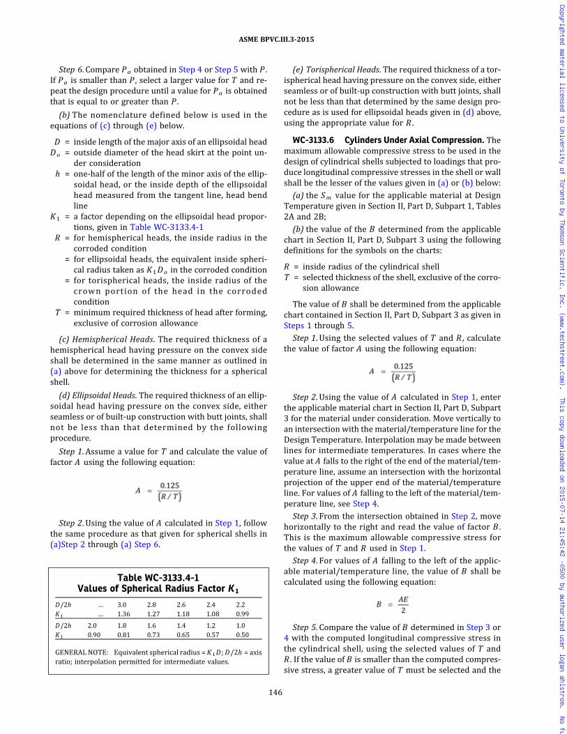
Step 6. Compare Pa obtained in Step 4 or Step 5 with P .If Pa is smaller than P , select a larger value for T and re-peat the design procedure until a value for Pa is obtainedthat is equal to or greater than P .
(b) The nomenclature defined below is used in theequations of (c) through (e) below.
D = inside length of the major axis of an ellipsoidal headDo = outside diameter of the head skirt at the point un-
der considerationh = one-half of the length of the minor axis of the ellip-
soidal head, or the inside depth of the ellipsoidalhead measured from the tangent line, head bendline
K1 = a factor depending on the ellipsoidal head propor-tions, given in Table WC-3133.4-1
R = for hemispherical heads, the inside radius in thecorroded condition
= for ellipsoidal heads, the equivalent inside spheri-cal radius taken as K1Do in the corroded condition
= for torispherical heads, the inside radius of thecrown portion of the head in the corrodedcondition
T = minimum required thickness of head after forming,exclusive of corrosion allowance
(c) Hemispherical Heads. The required thickness of ahemispherical head having pressure on the convex sideshall be determined in the same manner as outlined in(a) above for determining the thickness for a sphericalshell.
(d) Ellipsoidal Heads. The required thickness of an ellip-soidal head having pressure on the convex side, eitherseamless or of built‐up construction with butt joints, shallnot be less than that determined by the followingprocedure.
Step 1. Assume a value for T and calculate the value offactor A using the following equation:
Step 2. Using the value of A calculated in Step 1, followthe same procedure as that given for spherical shells in(a)Step 2 through (a) Step 6.
(e) Torispherical Heads. The required thickness of a tor-ispherical head having pressure on the convex side, eitherseamless or of built‐up construction with butt joints, shallnot be less than that determined by the same design pro-cedure as is used for ellipsoidal heads given in (d) above,using the appropriate value for R .
WC-3133.6 Cylinders Under Axial Compression. Themaximum allowable compressive stress to be used in thedesign of cylindrical shells subjected to loadings that pro-duce longitudinal compressive stresses in the shell or wallshall be the lesser of the values given in (a) or (b) below:
(a) the Sm value for the applicable material at DesignTemperature given in Section II, Part D, Subpart 1, Tables2A and 2B;
(b) the value of the B determined from the applicablechart in Section II, Part D, Subpart 3 using the followingdefinitions for the symbols on the charts:
R = inside radius of the cylindrical shellT = selected thickness of the shell, exclusive of the corro-
sion allowance
The value of B shall be determined from the applicablechart contained in Section II, Part D, Subpart 3 as given inSteps 1 through 5.
Step 1. Using the selected values of T and R , calculatethe value of factor A using the following equation:
Step 2. Using the value of A calculated in Step 1, enterthe applicable material chart in Section II, Part D, Subpart3 for the material under consideration. Move vertically toan intersection with the material/temperature line for theDesign Temperature. Interpolation may be made betweenlines for intermediate temperatures. In cases where thevalue at A falls to the right of the end of the material/tem-perature line, assume an intersection with the horizontalprojection of the upper end of the material/temperatureline. For values of A falling to the left of the material/tem-perature line, see Step 4.
Step 3. From the intersection obtained in Step 2, movehorizontally to the right and read the value of factor B .This is the maximum allowable compressive stress forthe values of T and R used in Step 1.
Step 4. For values of A falling to the left of the applic-able material/temperature line, the value of B shall becalculated using the following equation:
Step 5. Compare the value of B determined in Step 3 or4 with the computed longitudinal compressive stress inthe cylindrical shell, using the selected values of T andR . If the value of B is smaller than the computed compres-sive stress, a greater value of T must be selected and the
Table WC-3133.4-1Values of Spherical Radius Factor K 1
D/2h … 3.0 2.8 2.6 2.4 2.2K1 … 1.36 1.27 1.18 1.08 0.99
D/2h 2.0 1.8 1.6 1.4 1.2 1.0K1 0.90 0.81 0.73 0.65 0.57 0.50
GENERALNOTE: Equivalent spherical radius = K1D ;D/2h = axisratio; interpolation permitted for intermediate values.
146
ASME BPVC.III.3-2015
Copyrighted material licensed to University of Toronto by Thomson Scientific, Inc. (www.techstreet.com). This copy downloaded on 2015-07-14 21:45:42 -0500 by authorized user logan ahlstrom. No further reproduction or distribution is permitted.

ð15Þ
ð15Þ
design procedure repeated until a value of B is obtainedwhich is greater than the compressive stress computedfor the loading on the cylindrical shell.
WC-3135 Attachments
(a) Except as in (c) and (d) below, attachments andconnecting welds within the jurisdictional boundary ofthe containment as defined in WC-1130 shall meet thestress limits of the containment.
(b) The design of the containment shall include consid-eration of the interaction effects and loads transmittedthrough the attachment to and from the containment.Thermal stresses, stress concentrations, and restraint ofthe containment shall be considered.
(c) Beyond 2t from the outside surface of the contain-ment shell, where t is the nominal thickness of the con-tainment shell, the appropriate design rules of Division1, Article NF‐3000 may be used as a substitute for the de-sign rules of Article WC-3000 for portions of attachmentsthat are in the containment support load path.
(d) Nonstructural attachments shall meet the require-ments of WC-4435.
WC-3200 DESIGN RULES FORCONTAINMENTS
WC-3210 GENERAL REQUIREMENTSWC-3211 Basis for Use
WC-3211.1 Scope.(a) This subarticle contains design rules for contain-
ments used for storage of spent nuclear fuel and high levelradioactive material and waste. The design shall be suchthat stress intensities will not exceed the limits describedin this subarticle and in WC-3700 using the Sm values ta-bulated in Section II, Part D, Subpart 1, Tables 2A, 2B, and4.
(b) A stress analysis of containment shall be performedconsidering all the loadings of WC-3111 and the DesignSpecification. This analysis shall be done in accordancewith Section III Appendices, Mandatory Appendix XIII36
for all applicable stress categories. Alternatively, an ex-perimental stress analysis may be performed in accor-dance with Section III Appendices, Mandatory AppendixII.
(c) As an alternative, for energy-limited dynamicevents for which Level D Service Limits have been estab-lished, the strain-based acceptance criteria of WC-3700may be used rather than satisfying stress criteria as dis-cussed above.
(d) A Design Report shall be prepared by the CertificateHolder showing compliance with this subarticle. This De-sign Report shall meet the requirements of WA-3350 for aDesign Report (Section III Appendices, NonmandatoryAppendix C).
WC-3211.2 Requirements for Acceptability.(a) The design shall be such that the requirements of
WC-3100 and this subarticle are satisfied. In cases of con-flict, the requirements of this subarticle shall govern.
(b) The design shall be such that stress intensities donot exceed the limits given in WC-3217.
(c) For configurations where compressive stresses oc-cur, the critical buckling stress shall be taken into ac-count. The maximum allowable compressive stress to beused in the design of cylindrical shells subjected to load-ings that produce longitudinal compressive stress in theshell shall be the smaller of the following values:
(1) the Sm value from Section II, Part D, Subpart 1,Tables 2A and 2B
(2) the va lue of fac tor B determined fromWC-3133.6
(d) For the special case of external pressure, the rulesof WC-3133 shall be met.
WC-3211.3 Material in Combination. A containmentmay be designed for and constructed of combinations ofmaterials permitted in Section II, Part D, Subpart 1, Tables2A, 2B, and 4, provided the applicable rules are followed,including WC-3112.4, and the requirements in Section IXfor welding dissimilar metals are met.
WC-3211.4 Multiple Chamber Containment. When acontainment consists of more than one independentchamber, operating at the same or different pressuresand temperatures, each chamber shall be designed andconstructed to withstand the most severe condition of co-incident pressure and temperature expected.
WC-3211.5 Minimum Thickness of Shell or Head.The thickness after forming and without allowance forcorrosion of any containment shell or head subject topressure shall be not less than 1/4 in. (6 mm) for carbonand low alloy steels or 1/8 in. (3 mm) for stainless steel.
WC-3211.6 Selection of Material Thickness. The se-lected thickness of material shall be such that the forming,heat treatment, and other fabrication processes will notreduce the thickness of the material at any point belowthe minimum value required by these rules.
WC-3214 CladdingWC-3214.1 Primary Stresses. No structural strength
shall be attributed to the cladding in satisfying WC-3217primary stress limits.
WC-3214.2 Secondary and Peak Stresses. In satisfy-ing the secondary stress limits of WC-3217 and the fati-gue requirements of WC-3219, the presence of claddingshall be considered with respect to both thermal analysisand stress analysis. The stresses in both materials shall belimited to the values that meet the requirements of bothWC-3217 and WC-3219. However, when the cladding isof the integrally bonded type and the nominal thickness
147
ASME BPVC.III.3-2015
Copyrighted material licensed to University of Toronto by Thomson Scientific, Inc. (www.techstreet.com). This copy downloaded on 2015-07-14 21:45:42 -0500 by authorized user logan ahlstrom. No further reproduction or distribution is permitted.
of the cladding is 10% or less of the total thickness of thecontainment, the presence of the cladding may beneglected.
WC-32 14.3 Bearing Stresses. In sat is fy ingWC-3216.3, the presence of cladding shall be included.
WC-3215 Design BasisWC-3215.1 Pressure and Temperature Relation-
ships. The design shall take into account the maximumdifferences in pressure, temperature, and loadings, whichexist under the specified operating conditions, betweenthe inside and outside of the containment at any pointor between chambers of a multiple chamber containment.The design thickness for evaluating stresses due to pres-sure and other loadings shall not include any metal addedas corrosion or erosion allowance.
WC-3216 Design Stress Intensity ValuesWC-3216.1 Stress Tables. The design stress intensity
values Sm are given in Section II, Part D, Subpart 1, Tables2A, 2B, and 4. Values for intermediate temperatures maybe found by interpolation. These Sm values form the basisfor the various stress limits that are described in SectionIII Appendices, Mandatory Appendix XIII, and are used indetermining the membrane stress intensity limits for thevarious load combinations given in Table WC-3217-1.
WC-3216.2 Coefficient of Thermal Expansion andModulus of Elasticity. Values of the coefficient of thermalexpansion are in Section II, Part D, Subpart 2, Tables TEand values of the moduli of elasticity are in Section II, PartD, Subpart 2, Tables TM.
WC-3216.3 Special Stress Limits. The deviations be-tween (a), (b), and (c) below from the basic stress limitsa r e p rov ided t o cove r spe c i a l c ond i t i on s o rconfigurations.(a) Bearing Loads
(1) The average bearing stress for resistance tocrushing under the maximum design load shall be limitedto the yield strength Sy at temperature except that, whenthe distance to a free edge is greater than the distanceover which the bearing load is applied, a stress of 1.5Syat temperature is permitted. For clad surfaces, the yieldstrength of the base metal may be used if, when calculat-ing the bearing stress, the bearing area is taken as the les-ser of the actual contact or the area of the base metalsupporting the contact surface.
(2)When bearing loads are applied on parts havingfree edges, such as at a protruding ledge, the possibilityof a shear failure shall be considered. The average shearstress shall be limited to 0.6Sm in the case of design loadstress [Section III Appendices, Mandatory Appendix XIII,XIII-1123(l)] and 0.5Sy in the case of design load stressplus secondary stress [Section III Appendices, MandatoryAppendix XIII, XIII-1123(i)]. For clad surfaces, if the con-figuration or thickness is such that a shear failure couldoccur entirely within the clad material, the allowable
shear stress for the cladding shall be determined fromthe properties of the equivalent wrought material. If theconfiguration is such that a shear failure could occuracross a path that is partially base metal and partially cladmaterial, the allowable shear stresses for each materialshall be used when evaluating the combined resistanceto this type of failure.
(3)When considering bearing stresses in pins andsimilar members, the Sy value at temperature is applic-able, except that a value of 1.5Sy may be used if no creditis given to bearing area within one pin diameter from aplate edge.
(b) Pure Shear. The average primary shear stress acrossa section under Design Loadings in pure shear, for exam-ple, keys, shear rings, and screw threads, shall be limitedto 0.6Sm . The maximum primary shear under DesignLoadings, exclusive of stress concentration at the periph-ery of a solid circular section in torsion, shall be limited to0.8Sm .
(c) Progressive Distortion of Nonintegral Connections.Screwed‐on caps, screwed‐in plugs, shear ring closures,and breech lock closures are examples of nonintegral con-nections which are subject to failure by bell mouthing orother types of progressive deformation. If any combina-tion of applied loads produces yielding, such joints aresubject to ratcheting because the mating members maybecome loose at the end of each complete operating cycleand start the next cycle in a new relationship with eachother, with or without manual manipulation. Additionaldistortion may occur in each cycle so that interlockingparts, such as threads, can eventually lose engagement.Therefore, primary plus secondary stress intensifies (Sec-tion III Appendices, Mandatory Appendix XIII, XIII-1145),which result in slippage between parts of a nonintegralconnection in which disengagement could occur as a re-sult of progressive distortion, shall be limited to the valueSy given in Section II, Part D, Subpart 1, Table Y-1.
WC-3217 Design Criteria
These design requirements provide specific rules forcontainments. Simplified criteria are included for deter-mining whether analysis for cyclic operation is required.Stress analysis of the containment shall be performedusing the most severe combination of loadings expectedto occur simultaneously during design and operating con-ditions. Allowable stress intensities, kSm , for primarystresses shall be satisfied for all Service Limits. TableWC-3217-1 lists values of k that are appropriate for var-ious load combinations.
(a) The theory of failure used in this subarticle is themaximum shear stress theory. Stress intensity is definedas two times the maximum shear stress.
(b) The average value of the general primary mem-brane stress intensity across the thickness of the sectionunder consideration, Pm , due to any combination of
148
ASME BPVC.III.3-2015
Copyrighted material licensed to University of Toronto by Thomson Scientific, Inc. (www.techstreet.com). This copy downloaded on 2015-07-14 21:45:42 -0500 by authorized user logan ahlstrom. No further reproduction or distribution is permitted.

pressure and mechanical loadings expected to occur si-multaneously, should not exceed the design stress inten-sity value kSm .
(c) The local primary membrane stress intensity, PL
due to any combination of pressure and mechanical load-ings expected to occur simultaneously is limited to1.5kSm . The distance over which the stress intensity ex-ceeds 1.1kSm shall not extend in the meridional directionmore than , where R is the mean radius at the mid-surface of the containment shell or head and t is the nom-inal thickness of the shell or head at the point underconsideration.
(d) The general or local primary membrane plus bend-ing stress intensity (Pm or PL) + Pb due to any combina-tion of pressure and mechanical loadings expected tooccur simultaneously, shall not exceed 1.5kSm . The provi-sions of Section III Appendices, Mandatory Appendix XIIIapply.
WC-3217.1 Secondary Stresses. Secondary stressesmay exist in containments designed and fabricated in ac-cordance with the rules of this subarticle. Secondarystresses shall be evaluated in accordance with the rulesof Section III Appendices, Mandatory Appendix XIII. Sec-ondary stresses need be evaluated only for Level A Ser-vice Limits.
WC-3217.2 Peak Stresses. As described in Section IIIAppendices, Mandatory Appendix XIII, the peak stressesdo not cause any noticeable distortion and are objection-able only as a possible source of a fatigue crack or a brittlefracture. The allowable value of peak stress intensity isdependent on the stress intensity range and on the num-ber of times it is to be applied. If a fatigue analysis is
required, peak stresses shall be evaluated in accordancewith the fatigue analysis rules provided in Section III Ap-pendices, Mandatory Appendix XIV.36
WC-3217.3 Nomenclature.
Pb = primary bending stress intensity, psi (MPa). Thisstress intensity is the component of the primarystress proportional to the distance from the cen-troid of the solid section. It excludes discontinuitiesand concentrations and is produced only by pres-sure and other mechanical loads.
PL = local primary membrane stress intensity, psi(MPa). This stress intensity is derived from theaverage value across the solid section under con-sideration. It considers discontinuities but notconcentrations.
Pm = general primary membrane stress intensity, psi(MPa). This stress intensity is derived from theaverage value across the solid section under con-sideration. It excludes discontinuities and concen-trations and is produced only by pressure andother mechanical loads.
Sm = design stress intensity values given in Section II,Part D, Subpart 1, Tables 2A, 2B, and 4, psi (MPa)
Sy = yield strength values in Section II, Part D, Subpart1, Table Y-1, psi (MPa)
WC-3218 Upper Limits of Test Pressure
The evaluation of pressure test loadings shall be in ac-cordance with (a) through (d) below.
(a) Test Pressure Limit. If the calculated pressure at anypoint in a containment including static head, exceeds therequired test pressure defined in WC-6221 or WC-6321by more than 6%, the resulting stresses shall be calcu-lated using all the loadings that may exist during the test.The stress allowables for this situation are given in (b)and (c) below.
(b) Hydrostatically Tested Containments. The hydro-static test pressure of a completed containment shallnot exceed that value which results in the following stressintensity limits:
(1) a calculated primary membrane stress intensityPm of 90% of the tabulated yield strength Sy at test tem-perature as given in Section II, Part D, Subpart 1, TableY-1
(2) a calculated primary membrane plus primarybending stress intensity Pm + Pb shall not exceed the ap-plicable limits given in (-a) or (-b) below:
(-a) Pm + Pb ≤ 1.35 Sy for Pm ≤ 0.67 Sy(-b) P m + P b ≤ ( 2 . 1 5 S y − 1 . 2 P m ) f o r
0.67 Sy< Pm ≤ 0.90Sy
where Sy is the tabulated yield strength at test tempera-ture. For other than rectangular sections, Pm + Pb shallnot exceed a value of α times 0.90Sy , where the factor αis defined as the ratio of the load set producing a fullyplastic section divided by the load set producing initalyielding in the extreme fibers of the section.
Table WC-3217-1Stress Intensity k Factors for Design and
Operating Load Combinations
Service Limits [Note (1)] k [Note (2)]
Design 1.0Level A [Note (3)] 1.0Level C 1.2Level D [Note (4)]
NOTES:(1) For Design Limits, use Design Pressure at design metal
temperature; for Service Limits, use operating pressureat operating metal temperature.
(2) The condition of structural instability or buckling mustbe considered.
(3) See WC-3219 and Section III Appendices, MandatoryAppendix XIV.
(4) The stress limits of Section III Appendices, Nonmanda-tory Appendix F shall be applied. As an alternative, the re-quirements of WC-3700 may be used to evaluate inelasticcontainment responses to energy-limited dynamicevents.
149
ASME BPVC.III.3-2015
Copyrighted material licensed to University of Toronto by Thomson Scientific, Inc. (www.techstreet.com). This copy downloaded on 2015-07-14 21:45:42 -0500 by authorized user logan ahlstrom. No further reproduction or distribution is permitted.
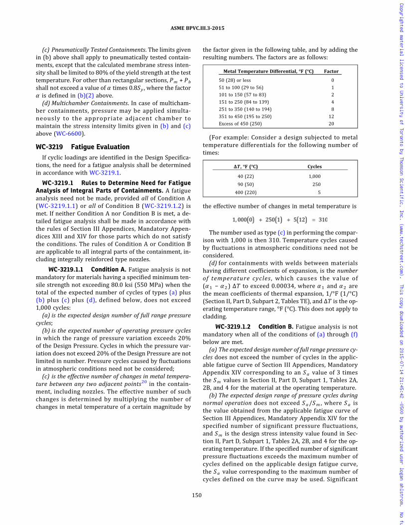
(c) Pneumatically Tested Containments. The limits givenin (b) above shall apply to pneumatically tested contain-ments, except that the calculated membrane stress inten-sity shall be limited to 80% of the yield strength at the testtemperature. For other than rectangular sections, Pm + Pb
shall not exceed a value of α times 0.8Sy , where the factorα is defined in (b)(2) above.(d) Multichamber Containments. In case of multicham-
ber containments, pressure may be applied simulta-neously to the appropriate adjacent chamber tomaintain the stress intensity limits given in (b) and (c)above (WC-6600).
WC-3219 Fatigue EvaluationIf cyclic loadings are identified in the Design Specifica-
tions, the need for a fatigue analysis shall be determinedin accordance with WC-3219.1.
WC-3219.1 Rules to Determine Need for FatigueAnalysis of Integral Parts of Containments. A fatigueanalysis need not be made, provided all of Condition A(WC-3219.1.1) or all of Condition B (WC-3219.1.2) ismet. If neither Condition A nor Condition B is met, a de-tailed fatigue analysis shall be made in accordance withthe rules of Section III Appendices, Mandatory Appen-dices XIII and XIV for those parts which do not satisfythe conditions. The rules of Condition A or Condition Bare applicable to all integral parts of the containment, in-cluding integrally reinforced type nozzles.
WC-3219.1.1 Condition A. Fatigue analysis is notmandatory for materials having a specified minimum ten-sile strength not exceeding 80.0 ksi (550 MPa) when thetotal of the expected number of cycles of types (a) plus(b) plus (c) plus (d), defined below, does not exceed1,000 cycles:(a) is the expected design number of full range pressure
cycles;(b) is the expected number of operating pressure cycles
in which the range of pressure variation exceeds 20%of the Design Pressure. Cycles in which the pressure var-iation does not exceed 20% of the Design Pressure are notlimited in number. Pressure cycles caused by fluctuationsin atmospheric conditions need not be considered;(c) is the effective number of changes in metal tempera-
ture between any two adjacent points20 in the contain-ment, including nozzles. The effective number of suchchanges is determined by multiplying the number ofchanges in metal temperature of a certain magnitude by
the factor given in the following table, and by adding theresulting numbers. The factors are as follows:
Metal Temperature Differential, °F (°C) Factor
50 (28) or less 0
51 to 100 (29 to 56) 1
101 to 150 (57 to 83) 2
151 to 250 (84 to 139) 4
251 to 350 (140 to 194) 8
351 to 450 (195 to 250) 12
Excess of 450 (250) 20
(For example: Consider a design subjected to metaltemperature differentials for the following number oftimes:
ΔT , °F (°C) Cycles
40 (22) 1,000
90 (50) 250
400 (220) 5
the effective number of changes in metal temperature is
The number used as type (c) in performing the compar-ison with 1,000 is then 310. Temperature cycles causedby fluctuations in atmospheric conditions need not beconsidered.(d) for containments with welds between materials
having different coefficients of expansion, is the numberof temperature cycles , which causes the value of(α1 − α2) ΔT to exceed 0.00034, where α1 and α2 arethe mean coefficients of thermal expansion, 1/°F (1/°C)(Section II, Part D, Subpart 2, Tables TE), and ΔT is the op-erating temperature range, °F (°C). This does not apply tocladding.
WC-3219.1.2 Condition B. Fatigue analysis is notmandatory when all of the conditions of (a) through (f)below are met.(a) The expected design number of full range pressure cy-
cles does not exceed the number of cycles in the applic-able fatigue curve of Section III Appendices, MandatoryAppendix XIV corresponding to an Sa value of 3 timesthe Sm values in Section II, Part D, Subpart 1, Tables 2A,2B, and 4 for the material at the operating temperature.(b) The expected design range of pressure cycles during
normal operation does not exceed Sa/Sm , where Sa isthe value obtained from the applicable fatigue curve ofSection III Appendices, Mandatory Appendix XIV for thespecified number of significant pressure fluctuations,and Sm is the design stress intensity value found in Sec-tion II, Part D, Subpart 1, Tables 2A, 2B, and 4 for the op-erating temperature. If the specified number of significantpressure fluctuations exceeds the maximum number ofcycles defined on the applicable design fatigue curve,the Sa value corresponding to the maximum number ofcycles defined on the curve may be used. Significant
150
ASME BPVC.III.3-2015
Copyrighted material licensed to University of Toronto by Thomson Scientific, Inc. (www.techstreet.com). This copy downloaded on 2015-07-14 21:45:42 -0500 by authorized user logan ahlstrom. No further reproduction or distribution is permitted.
pressure fluctuations are those for which the range ex-ceeds the quantity: Design Pressure times (1/3) timesS/Sm , where S is defined as follows:
(1) If the total specified number of operating cycles is106 cycles or less, S is the value of Sa obtained from theapplicable design fatigue curve for 106 cycles.
(2) If the total specified number of operating cyclesexceeds 106 cycles, S is the value of Sa obtained fromthe applicable design fatigue curve for the maximumnumber of cycles defined on the curve.
(c) The temperature difference in °F (°C) between anytwo adjacent points of the containment during normal op-eration does not exceed Sa/(2Eα), where Sa is the valueobtained from the applicable design fatigue curve for thespecified number of cycles, and α is the value of the in-stantaneous coefficient of thermal expansion at the meanvalue of the temperature at the two points, as given inSection II, Part D, Subpart 2, Tables TE. E is taken fromSection II, Part D, Subpart 2, Tables TM at the mean valueof the temperature at the two points.
(d) The range of temperature difference in °F (°C) be-tween any two adjacent points of the containment doesnot change during normal operation by more than thequantity Sa/(2Eα), where Sa is the value obtained fromthe applicable design fatigue curve for the total specifiednumber of significant temperature fluctuations. A tem-perature difference fluctuation shall be considered signif-icant if its total algebraic range exceeds the quantityS/(2Eα), where S is defined as follows:
(1) If the total specified number of operating cycles is106 cycles or less, S is the value of Sa obtained from theapplicable design fatigue curve for 106 cycles.
(2) If the total specified number of operating cyclesexceeds 106 cycles, S is the value of Sa obtained fromthe applicable design fatigue curve for the maximumnumber of cycles defined on the curve.
(e) For containments fabricated from materials of dif-fering elasticity or coefficients of thermal expansion, thetotal algebraic range of temperature fluctuation in °F(°C), experienced by the containment vessel during nor-mal operat ion does not exceed the magnitudeSa/[2(E1α1 − E2α 2 )], where Sa is the value obtainedfrom the applicable design fatigue curve for the total spe-cified number of significant temperature fluctuations, E1
and E2 are moduli of elasticity, and α1 and α2 are instan-taneous coefficients of thermal expansion at the meantemperature value involved for the two materials of con-struction (Section II, Part D, Subpart 2, Tables TE andTM). A temperature fluctuation shall be considered tobe significant if its total excursion exceeds the quantityS/[2(E1α1 − E2α2)], where S is defined as follows:
(1) If the total specified number of operating cycles is106 cycles or less, S is the value of Sa obtained from theapplicable design fatigue curve for 106 cycles.
(2) If the total specified number of operating cyclesexceeds 106 cycles, S is the value of Sa obtained fromthe applicable design fatigue curve for the maximum
number of cycles defined on the curve. If the two materi-als used have different applicable design fatigue curves,the lower value of Sa shall be used in applying rules ofthis Paragraph. This does not apply to cladding.
(f) The specified full range of mechanical loads, exclud-ing pressure, but including support or attachment reac-tions, does not result in load stress intensities whoserange exceeds the Sa value obtained from the applicabledesign fatigue curve for the total specified number of sig-nificant load fluctuations. If the total specified number ofsignificant load fluctuations exceeds the maximum num-ber of cycles defined on the applicable design fatiguecurve, the Sa value corresponding to the maximum num-ber of cycles defined on the curve may be used. A loadfluctuation shall be considered to be significant if the totalexcursion of load stress intensity exceeds the quantity S ,where S is defined as follows:
(1) If the total specified number of operating cycles is106 cycles or less, S is the value of Sa obtained from theapplicable design fatigue curve for 106 cycles.
(2) If the total specified number of operating cyclesexceeds 106 cycles, S is the value of Sa obtained fromthe applicable design fatigue curve for the maximumnumber of cycles defined on the curve.
WC-3220 DESIGN CONSIDERATIONWC-3224 Containments Under Internal Pressure
WC-3224.1 General Requirements. For calculatingthe required area of reinforcement of openings, the mini-mum thickness of the containment vessel and parts shallbe determined using the Design Pressure and the equa-tions in the following paragraphs. In addition, the otherDesign Loadings shall be considered in establishing thevalue of F as defined below.
WC-3224.2 Nomenclature. The symbols used are de-fined below. Except for test conditions, dimensions usedor calculated shall be in the corroded condition.
D = inside diameter of a head skirt or inside length of themajor axis of an ellipsoidal head at the point underconsideration measured perpendicular to the axisof revolution
F = meridional membrane force in the shell wall at thepoint under consideration resulting from primaryDesign Loadings other than internal pressure, lb/in. (N/mm) length of circumference. If this force isnot uniform, the loading requiring the greatest shellthickness shall be used where the tensile load ispositive.
h = one‐half the length of the minor axis of an ellipsoidalhead or the inside depth of an ellipsoidal head, mea-sured from the tangent line
k = stress intensity factor for design, Service Level A,and test load combination from Table WC-3217-1
L = inside spherical or crown radius of torispherical andhemispherical heads
151
ASME BPVC.III.3-2015
Copyrighted material licensed to University of Toronto by Thomson Scientific, Inc. (www.techstreet.com). This copy downloaded on 2015-07-14 21:45:42 -0500 by authorized user logan ahlstrom. No further reproduction or distribution is permitted.
ð15Þ
ð15Þ
P = internal pressure at the top of the containment ves-sel plus any pressure due to the static head of thefluid, at any point under consideration, psi (MPa)
R = inside radius of the shell under consideration, in.(mm). This radius is measured normal to the surfacefrom the axis of revolution.
r = inside knuckle radius of torispherical headsS = membrane stress intensity limit from Section II, Part
D, Subpart 1, Tables 2A and 2B multiplied by thestress intensity factor in Table WC-3217-1
= kSm psi (MPa)t = minimum thickness of shell
WC-3224.3 Minimum Thickness of CylindricalShells. The minimum thickness of cylindrical shells shallbe the greatest of the thicknesses determined by (a), (b),and (c) below.(a)
If P > 0.4S , the following equation must be used:
where ln is the natural log.(b) If F is positive and exceeds 0.5PR ,
(c) If F is negative, the condition of axial structural in-stability or buckling shall be considered separately [seeWC-3211.2(c)].
WC-3224.4 Minimum Thickness of Spherical Shells.The minimum thickness of spherical shells shall be thegreatest of the thicknesses determined by (a), (b), and(c) below.(a)
If P > 0.4S , the following equation may be used:
(b) If F is positive
(c) If F is negative, the condition of instability shall beconsidered. WC-3211.2(c) for cylinders may be used forspheres, provided biaxial compression does not exist.
WC-3224.5 Minimum Thickness of Formed Heads.The minimum thickness at the thinnest point after form-ing of ellipsoidal, torispherical, and hemispherical heads
under pressure acting against the concave surface shallbe determined by the appropriate rule or equation inthe following subparagraphs.
WC-3224.6 Minimum Thickness of EllipsoidalHeads.37, 38 The minimum thickness of a 2:1 ellipsoidalhead shall be established using the procedures given inWC-3224.8 and the curve of Figure WC-3224.6-1, whichis labeled “2:1 ellipsoidal head.” Ellipsoidal head designswhich have D/2h values different from 2 shall be ana-lyzed as equivalent torispherical heads or according toSection III Appendices, Mandatory Appendix II, XIII, orXIV. The cylindrical shell to which the head is attachedshall be equal to or greater in thickness than the requiredhead thickness for a distance, measured from the tangentline along the cylinder, of not less than . Transitionjoints to shells of thickness less than the required headthickness shall not be located within the minimum dis-tance. Transition joints to shells of thickness greater thanthe required head thickness may be located within thisminimum distance and shall be in accordance withWC-3260 and Figure WC-3261-1.
WC-3224.7 Minimum Thickness of HemisphericalHeads. For hemispherical heads, the thickness shall beas required for spherical shells, WC-3224.4. The require-ments for the transition to cylindrical shells of differentthickness, given in WC-3260 and Figure WC-3261-1 shallbe met.
WC-3224.8 Minimum Thickness of TorisphericalHeads.37 The minimum thickness of a torispherical headhaving t/L ≥ 0.002 up to a t/L where P/S ≤ 0.08 (ap-proximately t/L = 0.04 to 0.05) shall be established byusing the curves in Figure WC-3224.6-1. Interpolationmay be used for r/D values which fall within the rangeof curves; however, no extrapolation of the curves is per-mitted. For designs where P/S > 0.08, which is above theupper limit of Figure WC-3224.6-1, the thickness shall beset by the following equation:
where t/L < 0.002, which is below the lower limit ofFigure WC-3224.6-1, the head design must be analyzedaccording to Section III Appendices, Mandatory AppendixII, XIII, or XIV. The cylindrical shell to which the head isattached shall be equal to or greater in thickness thanthe required head thickness for a distance, measuredfrom the tangent line along the cylinder, of not less than
. Transition joints to shells of thickness less thanthe required head thickness shall not be located withinthis minimum distance. Transition joints to shells of thick-ness greater than the required head thickness may be lo-cated within this minimum distance and shall be inaccordance with WC-3260 and Figure WC-3261-1.
152
ASME BPVC.III.3-2015
Copyrighted material licensed to University of Toronto by Thomson Scientific, Inc. (www.techstreet.com). This copy downloaded on 2015-07-14 21:45:42 -0500 by authorized user logan ahlstrom. No further reproduction or distribution is permitted.

Figure WC-3224.6-1Design Curves for Torispherical Heads and 2:1 Ellipsoidal Heads for Use With WC-3224.8 and WC-3224.6
0.10
0.001
0.005
t/L
P/S
0.002 0.005
0.01
0.05
0.01 0.02
For 2:1 ellipsoidal heads, useL � 0.9D to calculate t/LCL
r/D
D/2
t
r
Lh
0.200.06
0.15
0.10
0.03 0.04 0.05
0.17 (2:1 ellipsoidal head)
153
ASME BPVC.III.3-2015
Copyrighted material licensed to University of Toronto by Thomson Scientific, Inc. (www.techstreet.com). This copy downloaded on 2015-07-14 21:45:42 -0500 by authorized user logan ahlstrom. No further reproduction or distribution is permitted.

ð15Þ
WC-3224.8.1 Crown and Knuckle Radii. In connec-tion with the design procedures of WC-3224.8 and FigureWC-3224.6-1, the inside crown radius to which an un-stayed head is formed shall not be greater than the insidediameter of the skirt of the head. The inside knuckle ra-dius of a torispherical head shall not be less than 6% ofthe outside diameter of the skirt nor less than three timesthe head thickness.
WC-3224.9 Loadings on Heads Other Than Pres-sure. Provision shall be made for other loadings givenin WC-3111. For torispherical and ellipsoidal heads, theeffect of other loadings must be determined in accordancewith Section III Appendices, Mandatory Appendix II, XIII,or XIV. For the spherical portion of heads, the effect ofcomposite loading may be treated as in WC-3224.3 andWC-3224.4.
WC-3225 Flat Heads and Covers
The minimum thickness of unstayed flat heads, coverplates, and blind flanges shall conform to the require-ments given in this Paragraph. Some acceptable types offlat heads and covers are shown in Figures WC-3225-1,WC-3225-2, and WC-3225-3. The dimensions are exclu-sive of extra metal added for corrosion allowance.
WC-3225.1 Nomenclature. The notations used aredefined as follows:
C = a factor depending upon the method of attachmentof head, shell dimensions, and other items as listedin Figures WC-3225-1 through WC-3225-3,dimensionless
D = bolt circle diameterd = diameter
hG = gasket moment arm, equal to the radial distancefrom the centerline of the bolts to the line of thegasket reaction, (Figure WC-3225-2)
L = distance from centerline of the head to shell weld totangent line on formed heads, as indicated in FigureWC-3225-2
m = the ratio t r/t s , dimensionlessP = Design Pressure, psi (MPa)r = inside corner radius on a head formed by flanging
or forgingS = design stress intensity Sm from Section II, Part D,
Subpart 1, Tables 2A, 2B, and 4, multiplied by thek factor tabulated in Table WC-3217-1, psi (MPa)
T = minimum required thickness of flat head, cover, orflanges, exclusive of corrosion allowance
t f = actual thickness of the flange on a formed head, atthe large end, exclusive of corrosion allowance
tp = the smallest dimension from the face of the head tothe edge of the weld preparation
tr = required thickness of shell or nozzle for pressuret s = actual thickness of shell or nozzleW = total bolt load
WC-3225.2 Equations for Minimum Thickness.39
(a) The thickness of flat heads as shown in FiguresWC-3225-1 through WC-3225-3, shall be not less thanthat calculated by the following equation:
(b) The thickness of cover plates and blind flanges at-tached by bolts causing an edge moment as shown inFigure WC-3225-2 shall be not less than that calculatedby the following equation:
NOTE: In some cases, the initial bolt load required to seat the gasketis larger than the operating bolt load. The thickness should bechecked for both the operating condition and the initial bolt load re-quired to seat the gasket.
WC-3230 OPENINGS AND REINFORCEMENT
WC-3231 General Requirements
(a) If the fatigue analysis exemption requirements ofWC-3219.1 are met, no specific fatigue analysis is re-quired for pressure loadings for locations in the vicinityof openings.
(b) The stress limits of Section III Appendices, Manda-tory Appendix XIII may also be considered to be satisfiedif, in the vicinity of an opening, the stress intensity result-ing from external nozzle loads and thermal effects, includ-ing gross but not structural discontinuities, is shown byanalysis to be less than 1.5Sm .
(c) The provisions of (a) and (b) above are not intendedto restrict the design to any specified section thicknessesor other design details provided the basic stress limits aresatisfied. If it is shown by analysis that the stress require-ments have been met, the rules of (d) through (g) arewaived.
(d) Openings shall be circular, elliptical, or of any othershape that results from the intersection of a circular or el-liptical cylinder with a containment vessel of the shapespermitted by this Division. If fatigue analysis is not re-quired, the restrictions on hole spacing in WC-3232.1are applicable, unless there will be essentially no reactionloads at these locations.
(e) All references to dimensions apply to the finisheddimensions excluding material added as corrosion allow-ance. Rules regarding metal available for reinforcementare given in WC-3235.
(f) Any type of opening permitted by these rules maybe located in a welded joint.
(g) Nozzles are limited to NPS 2 (DN 50) or smaller andshall be self‐reinforcing.
154
ASME BPVC.III.3-2015
Copyrighted material licensed to University of Toronto by Thomson Scientific, Inc. (www.techstreet.com). This copy downloaded on 2015-07-14 21:45:42 -0500 by authorized user logan ahlstrom. No further reproduction or distribution is permitted.
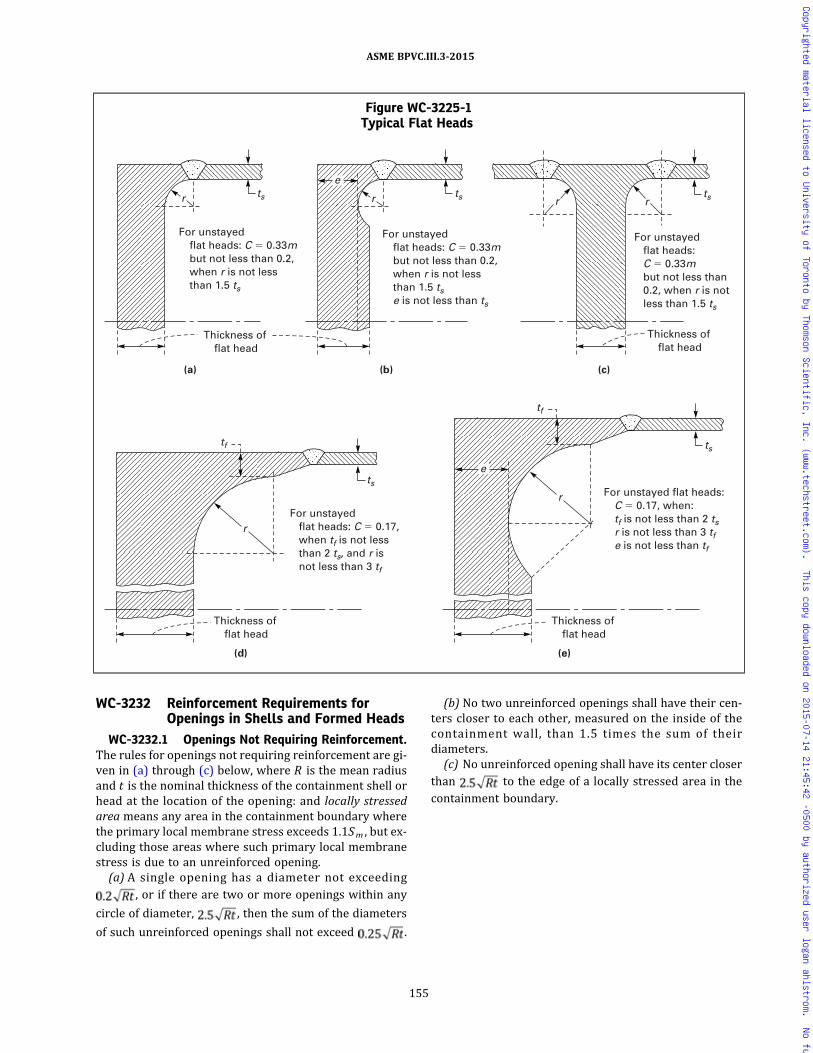
WC-3232 Reinforcement Requirements forOpenings in Shells and Formed Heads
WC-3232.1 Openings Not Requiring Reinforcement.The rules for openings not requiring reinforcement are gi-ven in (a) through (c) below, where R is the mean radiusand t is the nominal thickness of the containment shell orhead at the location of the opening: and locally stressedarea means any area in the containment boundary wherethe primary local membrane stress exceeds 1.1Sm , but ex-cluding those areas where such primary local membranestress is due to an unreinforced opening.
(a) A single opening has a diameter not exceeding, or if there are two or more openings within any
circle of diameter, , then the sum of the diameters
of such unreinforced openings shall not exceed .
(b) No two unreinforced openings shall have their cen-ters closer to each other, measured on the inside of thecontainment wall, than 1.5 times the sum of theirdiameters.
(c) No unreinforced opening shall have its center closerthan to the edge of a locally stressed area in thecontainment boundary.
Figure WC-3225-1Typical Flat Heads
ts
tf
r
(a) (b) (c)
Thickness offlat head
For unstayedflat heads: C � 0.33mbut not less than 0.2,when r is not lessthan 1.5 ts
For unstayedflat heads: C � 0.33mbut not less than 0.2,when r is not lessthan 1.5 tse is not less than ts
For unstayed flat heads: C � 0.17, when tf is not less than 2 ts, and r is not less than 3 tf
Thickness offlat head
r
r rrts
ts
(d)
Thickness offlat head
tf
ts
ts
(e)
Thickness offlat head
e
e
For unstayed flat heads:C � 0.17, when:tf is not less than 2 tsr is not less than 3 tfe is not less than tf
r
For unstayed flat heads: C � 0.33m but not less than 0.2, when r is not less than 1.5 ts
155
ASME BPVC.III.3-2015
Copyrighted material licensed to University of Toronto by Thomson Scientific, Inc. (www.techstreet.com). This copy downloaded on 2015-07-14 21:45:42 -0500 by authorized user logan ahlstrom. No further reproduction or distribution is permitted.

ð15ÞWC-3232.2 Required Area of Reinforcement. The to-tal cross‐sectional area of reinforcement A , required inany given plane for a containment under interal pressure,shall not be less than:
where
d = finished diameter of a circular opening or finisheddimension (chord length) of an opening on theplane being considered for elliptical and oblongopenings in corroded condition
F = a correction factor that compensates for the varia-tion in pressure stresses on different planes withrespect to the axis of containment vessel (a valueof 1.00 shall be used for all configurations, exceptthat Figure WC-3232.2-1 may be used for integrallyreinforced openings in cylindrical shells
t r = the thickness that meets the requirements ofWC-3220 in the absence of the opening
Not less than half the required material shall be on eachside of the centerline.
WC-3233 Required Reinforcement for Openingsin Flat Heads
Flat heads that have an opening with a diameter thatdoes not exceed one‐half of the head diameter shall havea total cross‐sectional area of reinforcement A , not lessthan that given by the equation:
where
d = the diameter as defined in WC-3232.2t r = the thickness that meets the requirements of
WC-3225.2 and as defined in WC-3232.2
WC-3234 Limits of Reinforcement
The boundaries of the cross‐sectional in any plane nor-mal to the containment wall and passing through the cen-ter of the opening within which metal shall be located inorder to have value as reinforcement are designated asthe limits of reinforcement for that plane and are givenin the following subparagraphs.
Figure WC-3225-2Some Acceptable Types of Unstayed Flat Heads and Covers
GENERAL NOTE: All these illustrations are diagrammatic only. Other designs that meet the requirements of WC-3225.2 are acceptable.
156
ASME BPVC.III.3-2015
Copyrighted material licensed to University of Toronto by Thomson Scientific, Inc. (www.techstreet.com). This copy downloaded on 2015-07-14 21:45:42 -0500 by authorized user logan ahlstrom. No further reproduction or distribution is permitted.

ð15ÞFigure WC-3225-3Attachment of Flat Heads to Containment Shell
ts
tp
a c
b
T
(a) (b)
ts
c L
a + b not less than 2ts
ts
b
b
T
c L c L
c L
a + b not less than 2ts
b + c not less than ts
C = 0.33m but not less than 0.2
(d)
C = 0.33m but not less than 0.2
C = 0.33m but not less than 0.2
(c)
ts
b
c
c
T
T
a + b but not less than 3ts
b + c not less than ts
ts
T
ts
b
c
b
(e)
C = 0.33m but not less than 0.2
c
T
ts
(g) (f)
C = 0.33m but not less than 0.2
C = 0.33m but not less than 0.2
T
c L
c
c c
a a
GENERAL NOTE: C min. = 0.7t s or1/4 in. (6 mm), whichever is less; b = the lesser of t s or T/2.
157
ASME BPVC.III.3-2015
Copyrighted material licensed to University of Toronto by Thomson Scientific, Inc. (www.techstreet.com). This copy downloaded on 2015-07-14 21:45:42 -0500 by authorized user logan ahlstrom. No further reproduction or distribution is permitted.

WC-3234.1 Limits of Reinforcement Along the Con-tainment Wall. The limits of reinforcement, measuredalong the midsurface of the nominal wall thickness ofthe containment, shall meet the following:(a) 100% of the required reinforcement shall be within
a distance on each side of the axis of the opening equal tothe greater of the following:
(1) the diameter of the finished opening in the cor-roded condition;
(2) the radius of the finished opening in the corrodedcondition plus the sum of the thicknesses of the contain-ment wall and the nozzle wall.(b) Two‐thirds of the required reinforcement shall be
within a distance on each side of the axis of the openingequal to the greater of the following:
(1) , where R is the mean radius of shellor head, t is the nominal containment wall thickness, andr is the radius of the finished opening in the corrodedcondition;
(2) the radius of the finished opening in the corrodedcondition plus two‐thirds the sum of the thicknesses ofthe containment wall and the nozzle wall.
WC-3235 Metal Available for Reinforcement
Metal may be counted as contributing to the area of re-inforcing called for in WC-3232, provided it lies withinthe limits of reinforcement specified in WC-3234, andshall be limited to material that meets the followingrequirements:(a)metal forming a part of the containment wall, which
is in excess of that required by WC-3232 and WC-3233,and is exclusive of corrosion allowance;(b) weld metal that is fully continuous with the contain-
ment weld;(c) the mean coefficient of thermal expansion of metal
to be included as reinforcement under (b) above shallbe within 15% of the value of the containment wallmaterial;(d)metal not fully continuous with the shell, such as
that in items attached by partial penetration welds, shallnot be counted as reinforcement;(e) metal available for reinforcement shall not be con-
sidered as applying to more than one opening.
WC-3236 Strength of Reinforcing Material
Material used for reinforcement shall preferably be thesame as that of the containment wall. If the material of thewall of the reinforcement has a lower design stress inten-sity value Sm than that for the containment material, theamount of area provided by the reinforcement in satisfy-ing WC-3232 orWC-3233 shall be taken as the actual areaprovided multiplied by the ratio of attachment wall pro-trusion or reinforcement design stress intensity value tothe containment material design stress intensity value.No reduction in the reinforcing required may be takenfor the increased strength of reinforcing material or forweld metal having higher design stress intensity valuesthan that of the material containment wall. The strengthof the material at the point under consideration shall beused in fatigue analyses.
WC-3250 DESIGN OF WELDED CONSTRUCTIONWC-3251 Welded Joint Categories
The term category defines the location of a joint in acontainment vessel but not the type of joint. The cate-gories are for use in specifying special requirements re-garding joint type and method of examination forcertain welded joints. Since these special requirements,which are based on service, material, and thickness, donot apply to every welded joint, only those joints to whichspecial requirements apply are included in the categories.The joints included in each category are designated asjoints of Categories A, B, C, and D. Figure WC-3251-1 illus-trates typical joint locations included in each category.
WC-3251.1 Category A. Category A comprises longi-tudinal welded joints within the main shell or nozzles;any welded joint within a sphere within a formed or flat
Figure WC-3232.2-1Chart for Determining the Value of F
1.00
0.95
0.90
0.85
0.80
0.75
0.70
0.65
0.60
0.55
0.500 10 20 30 40 50
Angle of Plane With Longitudinal Axis, deg
Valu
e o
f F
60 70 80 90
158
ASME BPVC.III.3-2015
Copyrighted material licensed to University of Toronto by Thomson Scientific, Inc. (www.techstreet.com). This copy downloaded on 2015-07-14 21:45:42 -0500 by authorized user logan ahlstrom. No further reproduction or distribution is permitted.

head, or within the side plates23 of a flat‐sided contain-ment; and circumferential welded joints connecting hemi-spherical heads to main shell or to nozzles.
WC-3251.2 Category B. Category B comprises cir-cumferential welded joints within the main shell or noz-zles, circumferential welded joints connecting formedheads other than hemispherical to main shells or tonozzles.
WC-3251.3 Category C. Category C comprises weldedjoints connecting flanges to formed heads or flat heads, tomain shell, and any welded joint connecting one side plateto another side plate of a flat‐sided vessel.
WC-3251.4 Category D. Category D compriseswelded joints connecting nozzles to main shells, tospheres, to heads, or to flat‐sided containments.
WC-3252 Permissible Types of Welded Joints
The design of the containment shall meet the require-ments for each category of joint. Butt joints are full pene-tration joints between plates or other elements that lieapproximately in the same plane. Figure WC-3251-2shows typical butt welds for each category joint.
WC-3252.1 Joints of Category A. All welded joints ofCategory A as defined in WC-3251 shall meet the fabrica-tion requirements of WC-4263 and shall be capable ofbeing examined in accordance with WC-5210.
WC-3252.2 Joints of Category B. All welded joints ofCategory B as defined in WC-3251 shall meet the fabrica-tion requirements of WC-4264 and shall be capable ofbeing examined in accordance with WC-5220. Whenjoints with opposing lips to form an integral backing stripor joints with backing strips not later removed are used,the suitability for cyclic service shall be analyzed by themethod of WC-3219.1 Condition B using a fatiguestrength reduction factor of not less than 2.
WC-3252.3 Joints of Category C. All welded joints ofCategory C, except for final closure welds (WC-3262),shall meet the fabrication requirements of WC-4265 andshall be capable of being examined in accordance withWC-5230. Minimum dimensions of welds and throatthickness shall be as shown in Figure WC-4265-1 where
(a) Figure WC-4265-1, sketches (a) and (b)(1) for forged flat heads and forged flanges with the
weld preparation bevel angle not greater than 45 deg.Measured from the face:
b = t s/2 or T/4, whichever is lessc = 0.7t s or
1/4 in. (6 mm), whichever is lessT, ts = nominal thickness of welded parts
(2) for all other material forms and for forged flatheads, and forged flanges with the weld preparation bevelangle greater than 45 deg. Measured from the face:
b = t s or T/2, whichever is lessc = 0.7t s or
1/4 in. (6 mm), whichever is lessT, ts = nominal thickness of welded parts
(b) Figure WC-4265-1, sketches (c) and (d)
c = 0.7t s or1/4 in. (6 mm), whichever is less
T, ts = nominal thickness of welded parts
(c) Figure WC-4265-1, sketch (e)
a + b = not less than 2t sb = not less than t stp = not less than t st s = actual thickness of shell
(d) Hubs for butt welding to the adjacent shell, head, orother containment part, as in Figure WC-4265-3, shall notbe machined from rolled plate. The component having thehub shall be forged in such a manner as to provide in thehub the full minimum tensile strength and elongation spe-cified for the material, in a direction parallel to the axis ofthe vessel. Proof of this shall be furnished by a tension
Figure WC-3251-1Welded Joint Locations Typical of Categories A, B, C, and D
A
A
A
A
D
A A
C
A
D
C
See WC-3262
B
B
159
ASME BPVC.III.3-2015
Copyrighted material licensed to University of Toronto by Thomson Scientific, Inc. (www.techstreet.com). This copy downloaded on 2015-07-14 21:45:42 -0500 by authorized user logan ahlstrom. No further reproduction or distribution is permitted.

ð15Þ
test specimen (subsize if necessary) taken in this direc-tion and as close to the hub as is practical. In FigureWC-4265-3, the minimum dimensions are as follows:
(1) sketch (a), r not less than 1.5t s(2) sketch (b), r not less than 1.5t s and e not less than
t s(3) sketch (c), r not less than 1.5t s(4) sketch (d), t f not less than 2t s and r not less than
3t f(5) sketch (e), t f not less than 2t s , r not less than 3t f ,
and e not less than t f
WC-3252.4 Joints of Category D. All welded joints ofCategory D, as defined in WC-3251, shall be in accordancewith the requirements of (a) through (e).(a) Butt-Welded Nozzles. Nozzles shall meet the fabrica-
tion requirements of WC-4266(a) and shall be capable ofbeing examined in accordance with WC-5242. The mini-mum dimensions and geometrical requirements of FigureWC-4266(a)-1 shall be met, where
r1 = 1/4t or3/4 in. (19 mm), whichever is less
r2 = 1/4 in. (6 mm) min.t = nominal thickness of part penetrated
tn = nominal thickness of penetrating part
(b) Full Penetration Corner-Welded Nozzles. Nozzlesshall meet the fabrication requirements of WC-4266(b)and shall be capable of being examined in accordancewith WC-5243. The minimum dimensions and geometri-cal requirements of Figure WC-4266(b)-1 shall be met,where
r1 = 1/4t or3/4 in. (19 mm), whichever is less
r2 = 1/4 in. (6 mm) min.t = nominal thickness of part penetratedt c = 0.7tn or 1/4 in. (6 mm), whichever is lesstn = nominal thickness of penetrating part
(c) Use of Deposited Weld Metal for Openings andNozzles.
(1) Nozzles shall meet the fabrication requirementsof WC-4266(c) and shall be capable of being examinedin accordance with WC-5244.
(2)When the deposited weld metal is used as rein-forcement, the coefficients of thermal expansion of thebase metal, the weld metal, and the connection shall notdiffer by more than 15% of the lowest coefficientinvolved.
(3) T h e m i n im um d im e n s i o n s o f F i g u r eWC-4266(c)-1 shall be met, where
r1 = 1/4t or3/4 in. (19 mm), whichever is less
Figure WC-3251-2Typical Butt Joints
160
ASME BPVC.III.3-2015
Copyrighted material licensed to University of Toronto by Thomson Scientific, Inc. (www.techstreet.com). This copy downloaded on 2015-07-14 21:45:42 -0500 by authorized user logan ahlstrom. No further reproduction or distribution is permitted.

ð15Þ
t = nominal thickness of part penetratedtc = 0.7tn or 1/4 in. (6 mm), whichever is lesstn = nominal thickness of penetrating part
(4) The corners of the end of each connection extend-
ing less than beyond the inner surface of the part
penetrated shall be rounded to a radius of one‐half thethickness tn of the connection or 3/4 in. (19 mm), which-ever is smaller.
(d) Fittings With Internal Threads. Internally threadedfittings shall be limited to NPS 2 (DN 50). Internallythreaded fittings shall be attached by means of full pene-tration groove welds meeting the fabrication require-ments of WC-4266(d) and shall be capable of beingexamined in accordance with WC-5245. The minimum di-mensions and geometrical requirements of FigureWC-4266(d)-1 shall be met, where
tc = 0.7 tn or 1/4 in. (6 mm), whichever is lesstn = nominal thickness of neck
(e) Attachment of Nozzles Using Partial PenetrationWelds. Partial penetration welds shall meet the fabrica-tion requirements of WC-4266(e) and shall be capableof being examined in accordance with WC-5245. Theyshall be used only for attachments such as instrumenta-tion openings and inspection openings, which are sub-jected to essentially no external mechanical loadingsand on which there will be no thermal stresses greaterthan those on the containment itself. Such attachmentsshall satisfy the requirements of WC-3231(g).
WC-3254 Structural Attachment Welds
Welds for structural attachments shall meet the re-quirements of WC-4432.
WC-3255 Welding Grooves
The dimensions and shape of the edges to be joinedshall be such as to permit complete fusion and completejoint penetration, except as otherwise permitted inWC-3252.4 or WC-3262.
WC-3259 Design Requirements for NozzleAttachment Welds and OtherConnections
The minimum design requirements for nozzle attach-ment welds and other connections are set forth in (a)and (b) below.
(a) Permitted Types of Nozzles and Other Connections.Nozzles and other connections may be any of the typesfor which rules are given in this subarticle, provided therequirements of (1) through (5) below are met.
(1) Nozzles shall meet requirements regardinglocation.
(2) The attachment weld shall meet the require-ments of WC-3252.4.
(3) The requirements of WC-3230 shall be met.
(4) Type No. 1 full penetration joints shall be usedwhen the openings are in shells 21/2 in. (64 mm) or morein thickness.
(5) The welded joints shall be examined by the meth-ods stipulated in WC-5240.
(b) Attachments. Typical attachments are shown inFigure WC-4433-2. The minimum dimensions in thisfigure are as follows:
where
c = minimum thickness of weld metal from the root tothe face of the weld
t = thickness of attached member
WC-3260 SPECIAL CONTAINMENTREQUIREMENTS
WC-3261 Category A or B Joints BetweenSections of Unequal Thickness
In general, a tapered transition section as shown inFigure WC-3261-1, shall be provided at joints of Cate-gories A and B between sections that differ in thicknessby more than one‐fourth the thickness of the thinner sec-tion. The transition section may be formed by any processthat will provide a uniform taper. An ellipsoidal or hemi-spherical head that has a greater thickness than a cylinderof the same inside diameter may be machined to the out-side diameter of the cylinder, provided the remainingthickness is at least as great as that required for a shellof the same diameter. A uniform taper is not requiredfor flanged hubs. The adequacy of the transition shall beevaluated by stress analysis. Stress intensity limitationsare given in Section III Appendices, Mandatory AppendixXIII. The requirements of this paragraph do not apply toflanged hubs.
WC-3262 Category C Full and PartialPenetration Closure Welds inContainments
WC-3262.1 Welds in the end closures using a singlecover plate [Figure WC-4265-3, sketch (a)] and madeafter the containment is loaded may be full or partial pe-netration and shall be examined in accordance with TableWC-3262-1 either by magnetic particle or liquid pene-trant method. The allowable stress intensity values of Sec-tion II, Part D, Subpart 1, Tables 2A, 2B, and 4 shall bereduced by the stress reduction factor provided in TableWC-3262-1. The welds shall be tested in accordance withWC-6720.
161
ASME BPVC.III.3-2015
Copyrighted material licensed to University of Toronto by Thomson Scientific, Inc. (www.techstreet.com). This copy downloaded on 2015-07-14 21:45:42 -0500 by authorized user logan ahlstrom. No further reproduction or distribution is permitted.

ð15Þ
WC-3262.2 For welds in the end closures using twocover plates [Figure WC-4265-3, sketch (b)] and madeafter the containment is loaded, the following apply:(a) The inner cover plate weld shall use a design stress
reduction factor of 0.9. The root and final layers shall beexamined by the liquid penetrant or magnetic particlemethod in accordance with Article WC-5000, and shallbe tested in accordance with WC-6720.
(b) The outer cover plate weld shall use the stress re-duction factors of Table WC-3262-1 and shall be exam-ined to the requirements of Table WC-3262-1.
WC-3262.3 Vent and drain cover plate welds may befull penetration welds examined in accordance withWC-5250 partial penetration welds using the examinationand stress reduction factors of Table WC-3262-1.
WC-3262.4 For partial penetration closure welds, afatigue strength reduction factor of not less than 4.0 shallbe used when fatigue analysis is required.
WC-3700 STRAIN-BASED ACCEPTANCECRITERIA
The strain-based acceptance criteria are applicableonly to the metallic portions of storage containments sub-ject to energy-limited dynamic events. It is not the intentof this subarticle to permit significant regions or majorportions of the containment to experience strains at ornear the limits of these strain-based acceptance criteriawithout consideration of the overall component deforma-tion. These strain-based acceptance criteria are estab-lished to address the regions of the containment thatexperience high strains due to the effects of direct im-pacts. Deformation limits, if any, provided in the DesignSpecification shall be satisfied.Section III Appendices, Nonmandatory Appendix FF
provides the strain-based acceptance criteria.
Figure WC-3261-1Categories A and B Joints Between Sections of
Unequal Thickness
GENERAL NOTE: Length of taper may include the width of the weld.
Table WC-3262-1Stress Reduction Factors and Examinations
for Closure Welds
Examination Requirements[Note (1)]
Stress ReductionFactors
Volumetric Examination 1.00
Liquid Penetrant or Magnetic ParticleExamination: Root and eachsuccessive 1/4 in. (6 mm) of weldthickness and the final layer
0.90
Liquid Penetrant or Magnetic ParticleExamination: Root, mid, and finallayer [Note (2)]
0.80
NOTES:(1) All examinations shall be performed and accepted to the re-
quirements of Article WC-5000.(2) Mid layer is defined as approximately one-half of the maximum
weld thickness.
162
ASME BPVC.III.3-2015
Copyrighted material licensed to University of Toronto by Thomson Scientific, Inc. (www.techstreet.com). This copy downloaded on 2015-07-14 21:45:42 -0500 by authorized user logan ahlstrom. No further reproduction or distribution is permitted.

ARTICLE WC-4000FABRICATION
WC-4100 GENERAL REQUIREMENTS
WC-4110 INTRODUCTION
Containments and parts shall be fabricated and in-stalled in accordance with the rules of this Article andshall be manufactured from materials that meet the re-quirements of Article WC-2000.
WC-4120 CERTIFICATION OF MATERIALS ANDFABRICATION BY CERTIFICATEHOLDER
WC-4121 Means of Certification
The Certificate Holder for an item shall certify, by appli-cation of the appropriate Certification Mark and comple-tion of the appropriate Data Report in accordance withArticle WA-8000, that the materials used comply withthe requirements of Article WC-2000 and that the fabrica-tion or installation complies with the requirements of thisArticle.
WC-4121.1 Certification of Treatments, Tests, andExaminations. If the Certificate Holder or Subcontractorperforms treatments, tests, repairs, or examinations re-quired by other paragraphs of this Article, the CertificateHolder shall certify that this requirement has been ful-filled (WA-3800). Reports of all required treatments andof the results of all required tests, repairs, and examina-tions performed shall be available to the Inspector.
WC-4121.2 Repetition of Tensile or Impact Tests. Ifduring the fabrication or installation of the item the mate-rial is subjected to heat treatment that has not been cov-ered by treatment of the test coupons (WC-2200) and thatmay reduce either tensile or impact properties below therequired values, the tensile and impact tests shall be re-peated by the Certificate Holder on test specimens takenfrom test coupons which have been taken and treated inaccordance with the requirements of Article WC-2000.
WC-4121.3 Repetition of Surface Examination AfterMachining. During the fabrication or installation of anitem, if containment materials are machined, then theCertificate Holder shall reexamine the surface of the ma-terial in accordance with WC-2500 when:
(a) the surface was required to be examined by themagnetic particle or liquid penetrant method in accor-dance with WC-2500; and
(b) the amount of material removed from the surfaceexceeds the lesser of 1/8 in. (3 mm) or 10% of the mini-mum required thickness of the part.
WC-4122 Materials Identification
(a)Material for performing a containment functionshall carry identification markings which will remain dis-tinguishable until the containment is assembled. If theoriginal identification markings are cut off or the materialis divided, either the marks shall be transferred to theparts cut or a coded marking shall be used to ensure iden-tification of each piece of material during subsequent fab-rication. In either case, an as‐built sketch or a tabulationof materials shall be made identifying each piece of mate-rial with the Certified Material Test Report, when applic-able, and the coded marking. For studs, bolts, and nuts itis permissible to identify the Certified Material Test Re-ports for material in each containment in lieu of identify-ing each piece of material with the Certified Material TestReport and the coded marking. Material supplied with aCertificate of Compliance and welding and brazing mate-rials shall be identified and controlled so that they can betraced to each containment or else a control procedureshall be used that ensures that the specified materialsare used.
(b)Material from which the identification marking islost shall be treated as nonconforming material until ap-propriate tests or other verifications are made and docu-mented to assure material identification. Testing isrequired unless positive identification can be made byother documented evidence. The material may then be re-marked upon establishing positive identification.
WC-4122.1 Marking Materials. Material shall bemarked in accordance with WC-2150.
WC-4123 Examinations
Visual examination activities that are not referenced forexamination by other specific Code paragraphs, and areperformed solely to verify compliance with requirementsof Article WC-4000, may be performed by the personswho perform or supervise the work. These visual exami-nations are not required to be performed by personneland procedures qualified to WC-5100 and WC-5500, re-spectively, unless so specified.
163
ASME BPVC.III.3-2015
Copyrighted material licensed to University of Toronto by Thomson Scientific, Inc. (www.techstreet.com). This copy downloaded on 2015-07-14 21:45:42 -0500 by authorized user logan ahlstrom. No further reproduction or distribution is permitted.

WC-4124 Additional Requirements WhenStrain-Based Acceptance Criteria HaveBeen Implemented
In order to satisfy the strain-based acceptance criteriaof WC-3700 regarding the locations of unique materialheats used in containment fabrication, traceability of allunique material heats and their specific location(s) ofuse shall be established and documented in the final De-sign Report and the as-built Design Drawings. This re-quirement is only necessary when strain-basedacceptance criteria have been employed in the design ofthe containment.
WC-4125 Testing of Welding and BrazingMaterials
All welding and brazing materials shall meet the re-quirements of WC-2400.
WC-4130 REPAIR OF MATERIALMaterial originally accepted on delivery in which de-
fects exceeding the limits of WC-2500 are known or dis-covered dur ing the proces s o f f abr i c a t i on i sunacceptable. The material may be used, provided thecondition is corrected in accordance with the require-ments of WC-2500 for the applicable product form, exceptthat:(a) the limitation on the depth of the weld repair does
not apply;(b) the time of examination of the weld repairs to weld
edge preparations shall be in accordance with WC-5130;(c) radiographic examination is not required for weld
repairs to seal membrane material when the materialthickness is 1/4 in. (6 mm) or less.(d)When the repair by welding provisions of WC-2539
are used within 1/2 in. (13 mm) on each side of the finalclosure welds, on canisters that are loaded with spentfuel, progressive examination of each deposited weldlayer by the magnetic particle method (WC-2545) or li-quid penetrant method (WC-2546), in addition to a finalsurface examination, may be substituted for the radio-graphic examination required by WC-2539.4. The thick-ness of each layer shall not exceed 1/4 in. (6 mm).
WC-4200 FORMING, CUTTING, ANDALIGNING
WC-4210 CUTTING, FORMING, AND BENDINGWC-4211 CuttingMaterials may be cut to shape and size by mechanical
means, such as machining, shearing, chipping, or grinding,or by thermal cutting.
WC-4211.1 Preheating Before Thermal Cutting.When thermal cutting is performed to prepare weld jointsor edges, to remove attachments or defective material, orfor any other purpose, consideration shall be given to
preheating the material, using preheat schedules suchas suggested in Section III Appendices, NonmandatoryAppendix D.
WC-4212 Forming and Bending Processes
Any process may be used to hot or cold form or bendcontainment materials, including weld metal, providedthe required dimensions are attained (see WC-4214 andWC-4220), and provided the impact properties of the ma-terials, when required, are not reduced below the mini-mum specified values, or they are effectively restoredby heat treatment following the forming operation. Hotforming is defined as forming with the material tempera-ture higher than 100°F (55°C) below the lower transfor-mation temperature of the material. When required, theprocess shall be qualified for impact properties as out-lined in WC-4213.
WC-4213 Qualification of Forming Processes forImpact Property Requirements
When impact testing is required by the Design Specifi-cations, a procedure qualification test shall be conductedusing specimens taken from materials of the same speci-fication, grade or class, heat treatment, and with similarimpact properties, as required for the material in thecomponent. These specimens shall be subjected to theequivalent forming or bending process and heat treat-ment as the material in the component. Applicable testsshall be conducted to determine that the required impactproperties of WC-2300 are met after straining.
WC-4213.1 Exemptions. Procedure qualificationtests are not required for material listed in (a) through(f) below:(a) hot formed material, such as forgings, in which the
hot forming is completed by the Material Organizationprior to removal of the impact test specimens;(b) hot formed materials represented by test coupons
required in either WC-2211 or WC-4121.2 that have beensubjected to heat treatment representing the hot formingprocedure and the heat treatments to be applied to theparts;(c) materials which do not require impacts in accor-
dance with WC-2300;(d)materials which have a final strain less than 0.5%;(e) material where the final strain is less than that of a
previously qualified procedure for that material;(f) material from which the impact testing required by
WC-2300 is performed on each heat and lot, as applicable,after forming.
WC-4213.2 Procedure Qualification Test. The proce-dure qualification test shall be performed in the mannerstipulated in (a) through (f) below.(a) The tests shall be performed on three different
heats of material, both before straining and after strainingand heat treatment, to establish the effects of the formingand subsequent heat treatment operations.
164
ASME BPVC.III.3-2015
Copyrighted material licensed to University of Toronto by Thomson Scientific, Inc. (www.techstreet.com). This copy downloaded on 2015-07-14 21:45:42 -0500 by authorized user logan ahlstrom. No further reproduction or distribution is permitted.
(b) Specimens shall be taken in accordance with the re-quirements of Article WC-2000 and shall be taken fromthe tension side of the strained material.
(c) The percent strain shall be established by the fol-lowing equations:
(1) For cylinders
(2) For spherical or dished surfaces
(3) For pipe
where
R = nominal bending radius to the center line of thepipe
Rf = final radius to center line of shellRo = original radius (equal to infinity for a flat part)r = nominal radius of the pipet = nominal thickness
(d) The procedure qualification shall simulate the max-imum percent surface strain, employing a bending pro-cess similar to that used in the fabrication of thematerial or by direct tension on the specimen.
(e) Sufficient Cv test specimens shall be taken fromeach of the three heats of material to establish a transitioncurve showing both the upper and lower shelves. On eachof the three heats, tests consisting of three impact speci-mens shall be conducted at a minimum of five differenttemperatures distributed throughout the transition re-gion. The upper and lower shelves may be establishedby the use of one test specimen for each shelf. Dependingon the product form, it may be necessary to plot the tran-sition curves using both the lateral expansion and energylevel data (WC-2300). In addition, drop weight tests shallbe made when required by WC-2300.
(f) Using the results of the impact test data from eachof three heats, taken both before and after straining, de-termine either:
(1) the maximum change in NDT temperature alongwith:
(-a) the maximum change of lateral expansion andenergy at the temperature under consideration; or
(-b) the maximum change in temperature at thelateral expansion and energy levels under consideration;or
(2)where lateral expansion is the acceptance criteria(WC-2300), either the maximum change in temperatureor the maximum change in lateral expansion.
WC-4213.3 Acceptance Criteria for Formed Materi-al. To be acceptable, the formed material used in the com-ponent shall have impact properties, before forming,sufficient to compensate for the maximum loss of impactproperties due to the qualified forming procedure used.
WC-4213.4 Requalification. A new procedure quali-fication test is required when any of the changes in (a),(b), or (c) below are made.
(a) The actual postweld heat treatment time at tem-perature is greater than previously qualified consideringWC-2211. If the material is not postweld heat-treated,the procedure must be qualified without postweld heattreatment.
(b) The maximum calculated strain of the material ex-ceeds the previously qualified strain by more than 0.5%.
(c) Where preheat over 250°F (120°C) is used in theforming or bending operation but not followed by a sub-sequent postweld heat treatment.
WC-4214 Minimum Thickness of FabricatedMaterial
If any fabrication operation reduces the thickness be-low the minimum required to satisfy the rules ofWC-2124 and Article WC-3000, the material may be re-paired in accordance with WC-4130.
WC-4220 FORMING TOLERANCESWC-4221 Tolerance for Containment Shells
Cylindrical, conical, or spherical shells of a completedcontainment, except formed heads covered by WC-4222,shall meet the requirements of the following subpara-graphs at all cross sections.
WC-4221.1 Maximum Difference in Cross-SectionalDiameters. The difference in inches (mm) between themaximum and minimum diameters at any cross‐sectionsha l l not exceed the smal ler o f (D + 50)/200[(D + 1,250)/200] and D/100, where D is the nominal in-side diameter, in. (mm), at the cross section under consid-eration. The diameters may be measured on the inside oroutside of the containment. If measured on the outside,the diameters shall be corrected for the plate thicknessat the cross section under consideration (FigureWC-4221.1-1). When the cross section passes throughan opening, the permissible difference in inside diametersgiven herein may be increased by 2% of the inside dia-meter of the opening.
WC-4221.2 Maximum Deviation From True Theore-tical Form for External Pressure. Containments designedfor external pressure shall meet the tolerances given in(a) through (e) below.
(a) The maximum plus or minus deviation from thetrue circular form of cylinders or the theoretical form ofother shapes, measured radially on the outside or insideof the containment, shall not exceed the maximum per-m i s s i b l e d e v i a t i o n o b t a i n e d f r om F i g u r e
165
ASME BPVC.III.3-2015
Copyrighted material licensed to University of Toronto by Thomson Scientific, Inc. (www.techstreet.com). This copy downloaded on 2015-07-14 21:45:42 -0500 by authorized user logan ahlstrom. No further reproduction or distribution is permitted.

WC-4221.2(a)-1. Measurements shall be made from a seg-mental circular template having the design inside or out-side radius depending on where the measurements aretaken and a chord length equal to twice the arc length ob-tained from Figure WC-4221.2(a)-2. For FigureWC-4221.2(a)-1, the maximum permissible deviation eneed not be less than 0.3t . For Figure WC-4221.2(a)-2,the arc length need not be greater than 0.30Do . Measure-ments shall not be taken on welds or other raised parts.(b) The value of t , in. (mm), at any cross section is the
nominal plate thickness less corrosion allowance for sec-tions of constant thickness and the nominal thickness ofthe thinnest plate less corrosion allowance for sectionshaving plates of more than one thickness.(c) The value of L in Figures WC-4221.2(a)-1 and
WC-4221.2(a)-2 is determined by (1) and (2) below.(1) For cylinders, L is as given in WC-3133.2.(2) For spheres, L is one‐half of the outside diameter
Do , in. (mm).(d) The dimensions of a completed containment may be
brought within the requirements by any process whichwill not impair the strength of the material.(e) Sharp bends and flat spots shall not be permitted
unless provision is made for them in the design.
WC-4221.3 Deviations From Tolerances. Deviationsfrom the tolerance requirements st ipulated inWC-4221.1 and WC-4221.2 are permitted, provided thedrawings are modified and reconciled with the designcalculations.
WC-4221.4 Tolerance Deviations for ContainmentParts Fabricated From Pipe. Containment parts sub-jected to either internal or external pressure and fabri-cated from pipe, meeting all other requirements of thisSubsection, may have variations of diameter and devia-tions from circularity permitted by the specification forsuch pipe.
WC-4221.5 Localized Thin Areas. Localized thinareas are permitted if the adjacent areas surroundingeach have sufficient thickness to provide the necessaryreinforcement according to the rules for reinforcementin WC-3232.2.
WC-4222 Tolerances for Formed Vessel Heads
The tolerance for formed vessel heads shall be as setforth in the following subparagraphs.
WC-4222.1 Maximum Difference in Cross-SectionalDiameters. The skirt or cylindrical end of a formed headshall be circular to the extent that the difference in inches(mm) between the maximum and minimum diametersdoe s no t e x c eed the l e s s e r o f (D + 50 )/200[(D + 1 250)/200] and (D + 12)/100 [(D + 300)/100],where D is the nominal inside diameter, in. (mm), andshall match the cylindrical edge of the adjoining partwithin the alignment tolerance specified in WC-4232.
WC-4222.2 Deviation From Specified Shape.(a) The inner surface of a torispherical or ellipsoidal
head shall not deviate outside the specified shape bymore than 11/4% of D , nor inside the specified shape bymore than 5/8% of D , where D is nominal inside diameterof the containment. Such deviations shall be measuredperpendicular to the specified shape and shall not beabrupt. The knuckle radius shall not be less than speci-fied. For 2:1 ellipsoidal heads, the knuckle radius maybe considered to be 17% of the diameter of thecontainment.
(b) Hemispherical heads and any spherical portion of aformed head shall meet the local tolerances for spheres asgiven in WC-4221.2, using L as the outside spherical ra-dius in inches (mm) and Do as 2 times L .
(c) Deviation measurements shall be taken on the sur-face of the base material and not on welds.
WC-4230 FITTING AND ALIGNINGWC-4231 Fitting and Aligning Methods
Parts that are to be joined by welding may be fitted,aligned, and retained in position during the welding op-eration by the use of bars, jacks, clamps, tack welds, ortemporary attachments.
WC-4231.1 Tack Welds. Tack welds used to securealignment shall either be removed completely when theyhave served their purpose, or their stopping and startingends shall be properly prepared by grinding or other sui-table means so that they may be satisfactorily incorpo-rated into the final weld. Tack welds shall be made byqualified welders using qualified welding procedures.When tack welds are to become part of the finished weld,they shall be visually examined and defective tack weldsremoved.
Figure WC-4221.1-1Maximum Difference in Cross-Sectional
Diameters
166
ASME BPVC.III.3-2015
Copyrighted material licensed to University of Toronto by Thomson Scientific, Inc. (www.techstreet.com). This copy downloaded on 2015-07-14 21:45:42 -0500 by authorized user logan ahlstrom. No further reproduction or distribution is permitted.
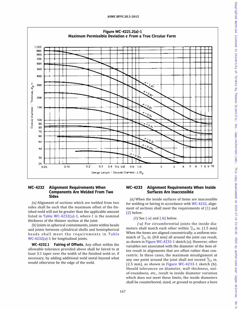
WC-4232 Alignment Requirements WhenComponents Are Welded From TwoSides
(a) Alignment of sections which are welded from twosides shall be such that the maximum offset of the fin-ished weld will not be greater than the applicable amountlisted in Table WC-4232(a)-1, where t is the nominalthickness of the thinner section at the joint.
(b) Joints in spherical containments, joints within headsand joints between cylindrical shells and hemisphericalheads sha l l mee t t he r equ i r emen t s i n Tab l eWC-4232(a)-1 for longitudinal joints.
WC-4232.1 Fairing of Offsets. Any offset within theallowable tolerance provided above shall be faired to atleast 3:1 taper over the width of the finished weld or, ifnecessary, by adding additional weld metal beyond whatwould otherwise be the edge of the weld.
WC-4233 Alignment Requirements When InsideSurfaces Are Inaccessible
(a)When the inside surfaces of items are inaccessiblefor welding or fairing in accordance with WC-4232, align-ment of sections shall meet the requirements of (1) and(2) below.
(1) See (-a) and (-b) below.
(-a) For circumferential joints the inside dia-meters shall match each other within 1/16 in. (1.5 mm)When the items are aligned concentrically, a uniform mis-match of 1/32 in. (0.8 mm) all around the joint can result,as shown in Figure WC-4233-1 sketch (a). However, othervariables not associated with the diameter of the item of-ten result in alignments that are offset rather than con-centric. In these cases, the maximum misalignment atany one point around the joint shall not exceed 3/32 in.(2.5 mm), as shown in Figure WC-4233-1 sketch (b).Should tolerances on diameter, wall thickness, out‐of‐roundness, etc., result in inside diameter variationwhich does not meet these limits, the inside diametersshall be counterbored, sized, or ground to produce a bore
Figure WC-4221.2(a)-1Maximum Permissible Deviation e From a True Circular Form
167
ASME BPVC.III.3-2015
Copyrighted material licensed to University of Toronto by Thomson Scientific, Inc. (www.techstreet.com). This copy downloaded on 2015-07-14 21:45:42 -0500 by authorized user logan ahlstrom. No further reproduction or distribution is permitted.
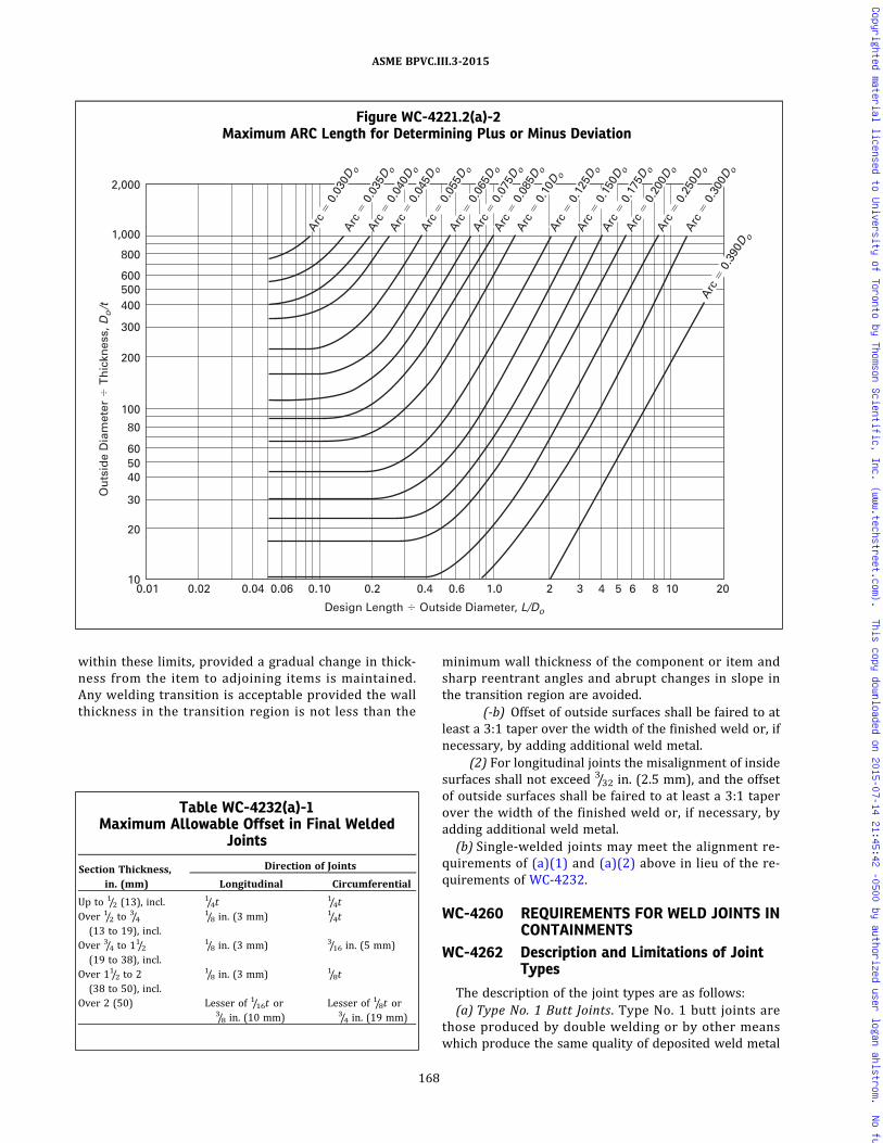
within these limits, provided a gradual change in thick-ness from the item to adjoining items is maintained.Any welding transition is acceptable provided the wallthickness in the transition region is not less than the
minimum wall thickness of the component or item andsharp reentrant angles and abrupt changes in slope inthe transition region are avoided.
(-b) Offset of outside surfaces shall be faired to atleast a 3:1 taper over the width of the finished weld or, ifnecessary, by adding additional weld metal.
(2) For longitudinal joints the misalignment of insidesurfaces shall not exceed 3/32 in. (2.5 mm), and the offsetof outside surfaces shall be faired to at least a 3:1 taperover the width of the finished weld or, if necessary, byadding additional weld metal.(b) Single-welded joints may meet the alignment re-
quirements of (a)(1) and (a)(2) above in lieu of the re-quirements of WC-4232.
WC-4260 REQUIREMENTS FOR WELD JOINTS INCONTAINMENTS
WC-4262 Description and Limitations of JointTypes
The description of the joint types are as follows:(a) Type No. 1 Butt Joints. Type No. 1 butt joints are
those produced by double welding or by other meanswhich produce the same quality of deposited weld metal
Figure WC-4221.2(a)-2Maximum ARC Length for Determining Plus or Minus Deviation
0.01 0.02 0.2 0.4 0.6 0.04 0.06 1.0 0.10 10
20
2,000
Design Length � Outside Diameter, L/Do
Ou
tsid
e D
iam
eter
� T
hic
knes
s, D
o/t
60 50 40
30
80
100
200
300
400 500 600
1,000
800
2 3 4 5 6 8 10 20
Arc
� 0
.030
D o
Arc
� 0
.040
D o
Arc
� 0
.045
D oA
rc �
0.0
55D o
Arc
� 0
.065
D o
Arc
� 0
.075
D o
Arc
� 0
.085
D o
Arc
� 0
.10D
o
Arc
� 0
.200
D o
Arc
� 0
.300
D o
Arc
� 0
.250
D o
Arc
� 0
.125
D oA
rc �
0.1
75D o
Arc
� 0
.150
D o
Arc
� 0
.035
D o
Arc
� 0
.390
D o
Table WC-4232(a)-1Maximum Allowable Offset in Final Welded
Joints
Section Thickness,in. (mm)
Direction of Joints
Longitudinal Circumferential
Up to 1/2 (13), incl.1/4t
1/4tOver 1/2 to
3/4(13 to 19), incl.
1/8 in. (3 mm) 1/4t
Over 3/4 to 11/2(19 to 38), incl.
1/8 in. (3 mm) 3/16 in. (5 mm)
Over 11/2 to 2(38 to 50), incl.
1/8 in. (3 mm) 1/8t
Over 2 (50) Lesser of 1/16t or3/8 in. (10 mm)
Lesser of 1/8t or3/4 in. (19 mm)
168
ASME BPVC.III.3-2015
Copyrighted material licensed to University of Toronto by Thomson Scientific, Inc. (www.techstreet.com). This copy downloaded on 2015-07-14 21:45:42 -0500 by authorized user logan ahlstrom. No further reproduction or distribution is permitted.

on both inside and outside weld surfaces. Welds usingbacking strips which remain in place do not qualify asType No. 1 butt joints. Type No. 1 butt joints shall havecomplete joint penetration and full fusion and shall meetthe requirements of WC-4424 and WC-4426.
(b) Type No. 2 Butt Joints. Type No. 2 butt joints aresingle-welded butt joints having backing strips which re-main in place. WC-3252.2 gives stress concentration fac-tors to be applied to Type No. 2 joints when a fatigueanalysis is required. When Type No. 2 butt joints are used,care shall be taken on aligning and separating the compo-nents to be joined so that there will be complete penetra-tion and fusion at the bottom of the joints for their full
length. However, weld reinforcement need be suppliedonly on the side opposite the backing strip. The require-ments of WC-4424 and WC-4426 shall be met.
(c) Full Penetration Corner Joints. Corner joints arethose connecting twomembers approximately at right an-gles to each other in the form of an L or T and shall bemade with full penetration welds (WC-3252.3). TypeNo. 1 corner-welded joints have full penetration weldsthat penetrate through the thickness of the shell [FigureWC-4265-1, sketches (a) and (b)]. Type No. 2 corner-welded joints have a full penetration weld that penetratesthrough the thickness of the head [Figure WC-4265-1,sketches (c), (d), and (e)].
Figure WC-4233-1Butt Weld Alignment and Mismatch Tolerances for Unequal I.D. and O.D. When Items Are Welded From
One Side and Fairing Is Not Performed
t
Centerline 2
(b) Offset Centerlines
(a) Concentric Centerlines
Centerline 1
3/32 in. (2.5 mm) maximum at any one point around the joint
1/32 in. (0.8 mm) maximum uniform mismatch around joint
CenterlineCenterline
t = nominal thickness, in. (mm)
169
ASME BPVC.III.3-2015
Copyrighted material licensed to University of Toronto by Thomson Scientific, Inc. (www.techstreet.com). This copy downloaded on 2015-07-14 21:45:42 -0500 by authorized user logan ahlstrom. No further reproduction or distribution is permitted.
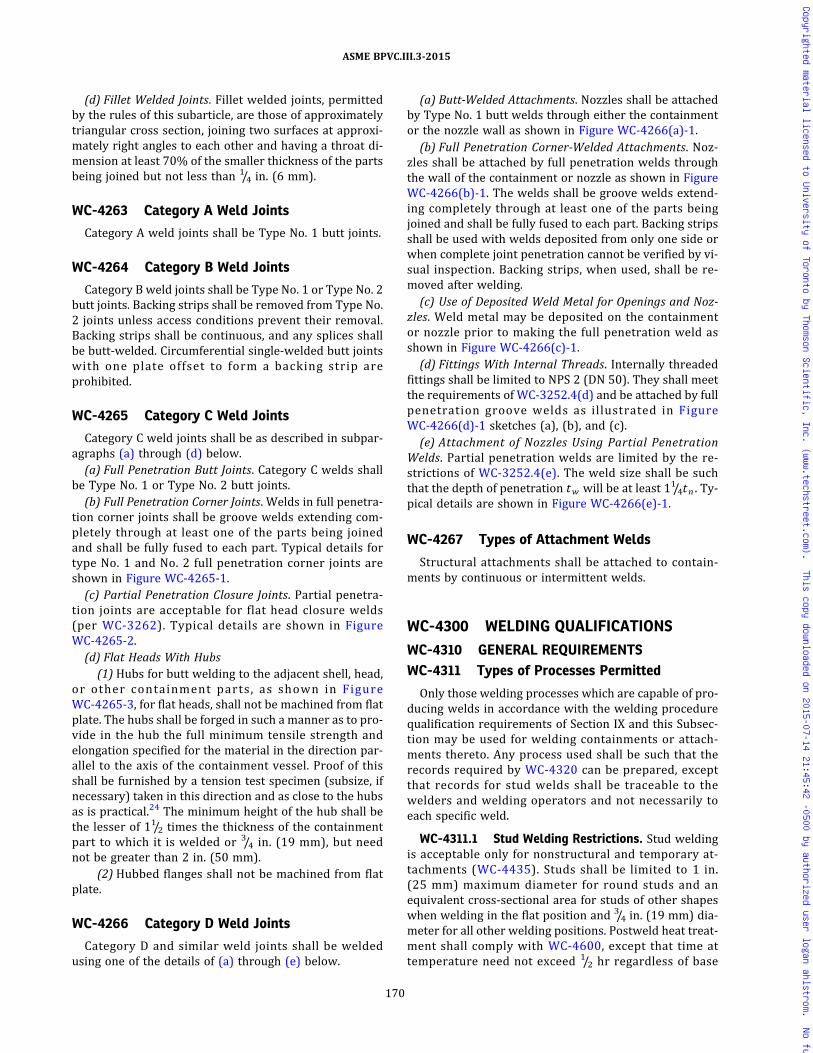
(d) Fillet Welded Joints. Fillet welded joints, permittedby the rules of this subarticle, are those of approximatelytriangular cross section, joining two surfaces at approxi-mately right angles to each other and having a throat di-mension at least 70% of the smaller thickness of the partsbeing joined but not less than 1/4 in. (6 mm).
WC-4263 Category A Weld Joints
Category A weld joints shall be Type No. 1 butt joints.
WC-4264 Category B Weld Joints
Category B weld joints shall be Type No. 1 or Type No. 2butt joints. Backing strips shall be removed from Type No.2 joints unless access conditions prevent their removal.Backing strips shall be continuous, and any splices shallbe butt-welded. Circumferential single-welded butt jointswith one plate offset to form a backing strip areprohibited.
WC-4265 Category C Weld Joints
Category C weld joints shall be as described in subpar-agraphs (a) through (d) below.(a) Full Penetration Butt Joints. Category C welds shall
be Type No. 1 or Type No. 2 butt joints.(b) Full Penetration Corner Joints. Welds in full penetra-
tion corner joints shall be groove welds extending com-pletely through at least one of the parts being joinedand shall be fully fused to each part. Typical details fortype No. 1 and No. 2 full penetration corner joints areshown in Figure WC-4265-1.(c) Partial Penetration Closure Joints. Partial penetra-
tion joints are acceptable for flat head closure welds(per WC-3262). Typical details are shown in FigureWC-4265-2.(d) Flat Heads With Hubs
(1) Hubs for butt welding to the adjacent shell, head,or other containment parts, as shown in FigureWC-4265-3, for flat heads, shall not be machined from flatplate. The hubs shall be forged in such a manner as to pro-vide in the hub the full minimum tensile strength andelongation specified for the material in the direction par-allel to the axis of the containment vessel. Proof of thisshall be furnished by a tension test specimen (subsize, ifnecessary) taken in this direction and as close to the hubsas is practical.24 The minimum height of the hub shall bethe lesser of 11/2 times the thickness of the containmentpart to which it is welded or 3/4 in. (19 mm), but neednot be greater than 2 in. (50 mm).
(2) Hubbed flanges shall not be machined from flatplate.
WC-4266 Category D Weld Joints
Category D and similar weld joints shall be weldedusing one of the details of (a) through (e) below.
(a) Butt-Welded Attachments. Nozzles shall be attachedby Type No. 1 butt welds through either the containmentor the nozzle wall as shown in Figure WC-4266(a)-1.(b) Full Penetration Corner-Welded Attachments. Noz-
zles shall be attached by full penetration welds throughthe wall of the containment or nozzle as shown in FigureWC-4266(b)-1. The welds shall be groove welds extend-ing completely through at least one of the parts beingjoined and shall be fully fused to each part. Backing stripsshall be used with welds deposited from only one side orwhen complete joint penetration cannot be verified by vi-sual inspection. Backing strips, when used, shall be re-moved after welding.(c) Use of Deposited Weld Metal for Openings and Noz-
zles. Weld metal may be deposited on the containmentor nozzle prior to making the full penetration weld asshown in Figure WC-4266(c)-1.(d) Fittings With Internal Threads. Internally threaded
fittings shall be limited to NPS 2 (DN 50). They shall meetthe requirements of WC-3252.4(d) and be attached by fullpenetration groove welds as illustrated in FigureWC-4266(d)-1 sketches (a), (b), and (c).(e) Attachment of Nozzles Using Partial Penetration
Welds. Partial penetration welds are limited by the re-strictions of WC-3252.4(e). The weld size shall be suchthat the depth of penetration tw will be at least 11/4tn . Ty-pical details are shown in Figure WC-4266(e)-1.
WC-4267 Types of Attachment Welds
Structural attachments shall be attached to contain-ments by continuous or intermittent welds.
WC-4300 WELDING QUALIFICATIONS
WC-4310 GENERAL REQUIREMENTSWC-4311 Types of Processes Permitted
Only those welding processes which are capable of pro-ducing welds in accordance with the welding procedurequalification requirements of Section IX and this Subsec-tion may be used for welding containments or attach-ments thereto. Any process used shall be such that therecords required by WC-4320 can be prepared, exceptthat records for stud welds shall be traceable to thewelders and welding operators and not necessarily toeach specific weld.
WC-4311.1 Stud Welding Restrictions. Stud weldingis acceptable only for nonstructural and temporary at-tachments (WC-4435). Studs shall be limited to 1 in.(25 mm) maximum diameter for round studs and anequivalent cross‐sectional area for studs of other shapeswhen welding in the flat position and 3/4 in. (19 mm) dia-meter for all other welding positions. Postweld heat treat-ment shall comply with WC-4600, except that time attemperature need not exceed 1/2 hr regardless of base
170
ASME BPVC.III.3-2015
Copyrighted material licensed to University of Toronto by Thomson Scientific, Inc. (www.techstreet.com). This copy downloaded on 2015-07-14 21:45:42 -0500 by authorized user logan ahlstrom. No further reproduction or distribution is permitted.

material thickness. Welding procedure and performancequalification shall comply with the requirements of Sec-tion IX.
WC-4311.2 Capacitor Discharge Welding. Capacitordischarge welding may be used for welding temporary at-tachments and permanent nonstructural attachmentsprovided:
(a) temporary attachments are removed in accordancewith the provisions of WC-4435(b);
(b) the energy output for permanent nonstructural at-tachments such as strain gages and thermocouples is lim-ited to 125 W‐sec and the minimum thickness of thematerial to which the attachment is made is greater than0.09 in. (2 mm); and
(c) a Welding Procedure Specification is prepared de-scribing the capacitor discharge equipment, the combina-tion of materials to be joined, and the technique ofapplication; qualification of the welding procedure isnot required.
WC-4320 WELDING QUALIFICATIONS, RECORDS,AND IDENTIFYING STAMPS
WC-4321 Required Qualifications
(a) Each Certificate Holder is responsible for the weld-ing done by his organization, and he shall establish theprocedure and conduct the tests required by this Articleand by Section IX in order to qualify both the welding pro-cedures and the performance of welders and welding op-erators who apply these procedures.
(b) Procedures, welders, and welding operators used tojoin permanent or temporary attachments to contain-ments and to make permanent or temporary tack weldsused in such welding shall also meet the qualification re-quirements of this Article.
(c) When making procedure test plates for butt welds,consideration shall be given to the effect of angular, lat-eral, and end restraint on the weldment. This applies par-ticularly to material and weld metal of 80.0 ksi (550 MPa)tensile strength or higher and heavy sections of both lowand high tensile strength material. The addition of re-straint during welding may result in cracking difficultiesthat otherwise might not occur.
Figure WC-4265-1Acceptable Full Penetration Weld Details for Category C Joints
GENERAL NOTE: For definitions of nomenclature, see WC-3252.3.
171
ASME BPVC.III.3-2015
Copyrighted material licensed to University of Toronto by Thomson Scientific, Inc. (www.techstreet.com). This copy downloaded on 2015-07-14 21:45:42 -0500 by authorized user logan ahlstrom. No further reproduction or distribution is permitted.

ð15Þ
WC-4322 Maintenance and Certification ofRecords
The Certificate Holder shall maintain a record of hisqualified welding procedures and of the welders andwelding operators qualified by him, showing the dateand results of tests and the identification mark assignedto each welder. These records shall be reviewed, verified,and certified by the Certificate Holder by signature orsome other method of control in accordance with the Cer-tificate Holder’s Quality Assurance Program and shall beavailable to the Authorized Nuclear Inspector.
WC-4322.1 Identification of Joints by Welder orWelding Operator.(a) Each welder or welding operator shall apply the
identification mark assigned to him by the CertificateHolder on or adjacent to all permanent welded joints orseries of joints on which he welds. The marking shall beat intervals of 3 ft (1 m) or less and shall be done witheither blunt nose continuous or blunt nose interrupteddot die stamps. As an alternative, the Certificate Holder
shall keep a record of permanent welded joints in eachitem and of the welders and welding operators used inmaking each of the joints.(b)When a multiple number of permanent structural
attachment welds, nonstructural welds, fillet welds, sock-et welds, weld metal cladding, and hard surfacing weldsare made on an item, the Certificate Holder need not iden-tify the welder or welding operator who welded each in-dividual joint, provided:
(1) the Certificate Holder maintains a system thatwill identify the welders or welding operators who madesuch welds on each item so that the Inspector can verifythat the welders or welding operators were all properlyqualified;
(2) the welds in each category are all of the sametype and configuration and are welded with the sameWelding Procedure Specification.(c) Welder or welding operator identification is not re-
quired for tack welds.
WC-4323 Welding Prior to Qualifications
No welding shall be undertaken until after the weldingprocedures which are to be used have been qualified.Only welders and welding operators who are qualifiedin accordance with WC-4320 and Section IX shall be used.
WC-4324 Transferring Qualifications
The welding procedure qualifications and performancequalification tests for welders and welding operators con-ducted by one Certificate Holder shall not qualify weldingprocedures, and shall not qualify welders or welding op-erators to weld for any other Certificate Holder, except asprovided in Section IX.
WC-4330 GENERAL REQUIREMENTS FORWELDING PROCEDUREQUALIFICATION TESTS
WC-4331 Conformance to Section IXRequirements
All welding procedure qualification tests shall be in ac-cordance with the requirements of Section IX as supple-mented or modified by the requirements of this Article.
WC-4333 Heat Treatment of Qualification Weldsfor Ferritic Materials
Postweld heat treatment of procedure qualificationwelds shall conform to the applicable requirements ofWC-4600 and Section IX. The postweld heat treatmenttime at temperature is to be at least 80% of the maximumtime to be applied to the component weld material. Thepostweld heat treatment total time may be applied inone heating cycle.
Figure WC-4265-2Typical Partial Penetration Weld Detail for
Category C Flat Head Closure Joints
t � shell thickness
(a) Single Closure Weld Detail
(b) Double Closure Weld Detail
t
172
ASME BPVC.III.3-2015
Copyrighted material licensed to University of Toronto by Thomson Scientific, Inc. (www.techstreet.com). This copy downloaded on 2015-07-14 21:45:42 -0500 by authorized user logan ahlstrom. No further reproduction or distribution is permitted.

WC-4334 Preparation of Test Coupons andSpecimens
(a) Removal of test coupons from the test weld and thedimensions of specimens made from them shall conformto the requirements of Section IX, except that the removalof impact test coupons and the dimensions of impact testspecimens shall be in accordance with (b) below.
(b)Weld deposit of each process in a multiple processweld shall, where possible, be included in the impact testspecimens. When each process cannot be included in thefull size impact test specimen at the 1/4t location requiredby this Section, additional full size specimens shall be ob-tained from locations in the test weld that will ensure thatat least a portion of each process has been included in full
size test specimens. As an alternative, additional testwelds can be made with each process so that full size spe-cimens can be tested for each process.
WC-4334.1 Coupons Representing the Weld Depos-its. Impact test specimens and testing methods shall con-form to WC-2321. The impact specimen shall be locatedso that the longitudinal axis of the specimen is at least1/4t and, where the thickness of the test assembly permits,not less than 3/8 in. (10 mm) from the weld surface of thetest assembly. In addition, when the postweld heat treat-ment temperature exceeds the maximum temperaturespecified in WC-4620, and the test assembly is cooled atan accelerated rate, the longitudinal axis of the specimenshall be a minimum of t from the edge of the test
Figure WC-4265-3Typical Flat Heads
Tension test specimen
Tension test specimen
Tension test specimen
ts
tf
r
(a) (b) (c)
Thickness offlat head
Thickness offlat head
Tension test specimen
r rrts
ts
(d)
Thickness offlat head
tf
ts
ts
(e)
Thickness offlat head
e
e
GENERAL NOTE: For definition of nomenclature, see WC-3225.
173
ASME BPVC.III.3-2015
Copyrighted material licensed to University of Toronto by Thomson Scientific, Inc. (www.techstreet.com). This copy downloaded on 2015-07-14 21:45:42 -0500 by authorized user logan ahlstrom. No further reproduction or distribution is permitted.
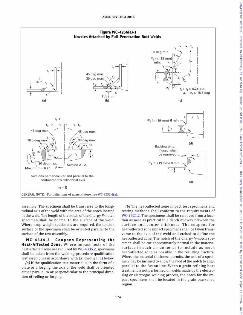
assembly. The specimen shall be transverse to the longi-tudinal axis of the weld with the area of the notch locatedin the weld. The length of the notch of the Charpy V‐notchspecimen shall be normal to the surface of the weld.Where drop weight specimens are required, the tensionsurface of the specimen shall be oriented parallel to thesurface of the test assembly.
W C - 4 3 3 4 . 2 C o u p o n s R e p r e s e n t i n g t h eHeat-Affected Zone. Where impact tests of theheat-affected zone are required by WC-4335.2, specimensshall be taken from the welding procedure qualificationtest assemblies in accordance with (a) through (c) below.(a) If the qualification test material is in the form of a
plate or a forging, the axis of the weld shall be orientedeither parallel to or perpendicular to the principal direc-tion of rolling or forging.
(b) The heat-affected zone impact test specimens andtesting methods shall conform to the requirements ofWC-2321.2. The specimens shall be removed from a loca-tion as near as practical to a depth midway between thesurface and center thickness . The coupons forheat-affected zone impact specimens shall be taken trans-verse to the axis of the weld and etched to define theheat-affected zone. The notch of the Charpy V‐notch spe-cimen shall be cut approximately normal to the materialsurface in such a manner as to include as muchheat-affected zone as possible in the resulting fracture.Where the material thickness permits, the axis of a speci-menmay be inclined to allow the root of the notch to alignparallel to the fusion line. When a grain refining heattreatment is not performed on welds made by the electro-slag or electrogas welding process, the notch for the im-pact specimens shall be located in the grain coarsenedregion.
Figure WC-4266(a)-1Nozzles Attached by Full Penetration Butt Welds
tn
t 1 3
r2
r1
(a)
tn
tn
te
t
45 deg max.
30 deg min.
30 deg max. r2
r2
r1
r1
t3
r2
t4
a2 t3 + t4 � 0.2t, but a1 + a2 � 18.5 deg
a1 t
t
r2
r1
tn
(b)
11/2 t min
1/2 in. (13 mm) min.
Backing strip, if used, shall be removed
(c)
(d)
r1 t
t tn
tn
r1 r1
r2
tn
3/4 in. (19 mm) R min.
3/4 in. (19 mm) R min.
(e)
r2
r2
r2
r2
r2
45 deg max. 45 deg max.
A
A
Maximum = 0.2t
18.5 deg max.
Sections perpendicular and parallel to the containment’s cylindrical axis
Section A - A
(c – 1)
30 deg max.
30 deg max.
t
GENERAL NOTE: For definitions of nomenclature, see WC-3252.4(a).
174
ASME BPVC.III.3-2015
Copyrighted material licensed to University of Toronto by Thomson Scientific, Inc. (www.techstreet.com). This copy downloaded on 2015-07-14 21:45:42 -0500 by authorized user logan ahlstrom. No further reproduction or distribution is permitted.
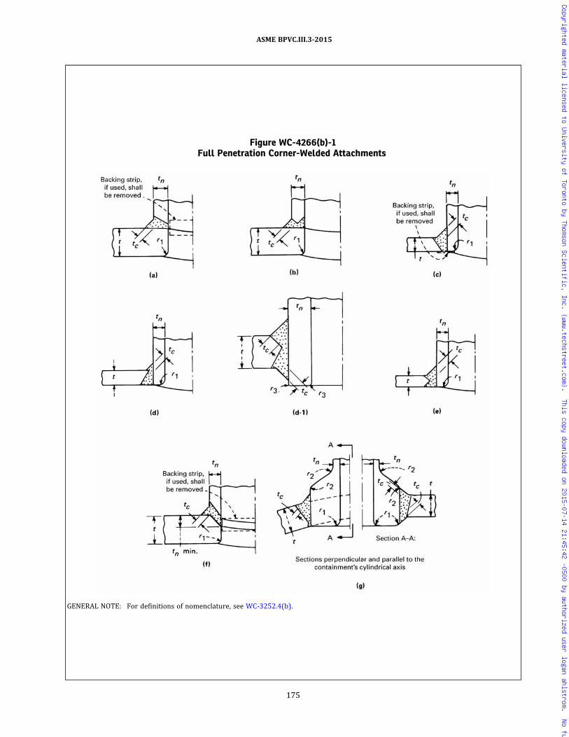
Figure WC-4266(b)-1Full Penetration Corner-Welded Attachments
GENERAL NOTE: For definitions of nomenclature, see WC-3252.4(b).
175
ASME BPVC.III.3-2015
Copyrighted material licensed to University of Toronto by Thomson Scientific, Inc. (www.techstreet.com). This copy downloaded on 2015-07-14 21:45:42 -0500 by authorized user logan ahlstrom. No further reproduction or distribution is permitted.
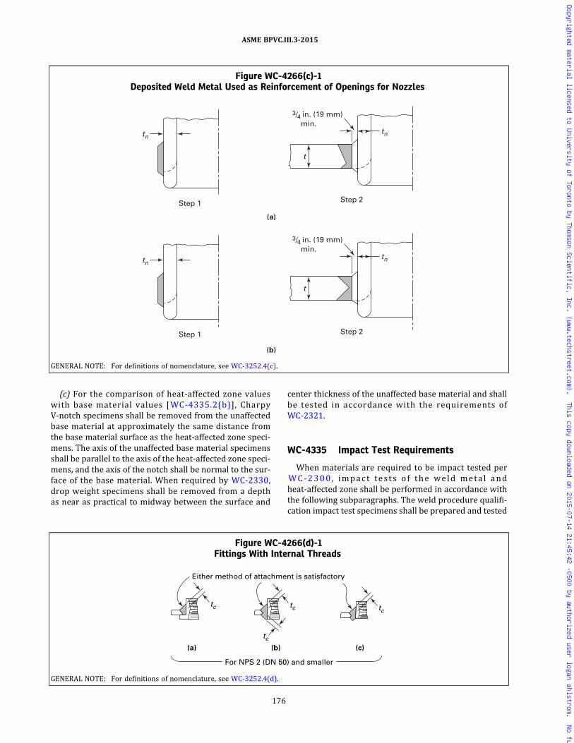
(c) For the comparison of heat-affected zone valueswith base material values [WC-4335.2(b)], CharpyV‐notch specimens shall be removed from the unaffectedbase material at approximately the same distance fromthe base material surface as the heat-affected zone speci-mens. The axis of the unaffected base material specimensshall be parallel to the axis of the heat-affected zone speci-mens, and the axis of the notch shall be normal to the sur-face of the base material. When required by WC-2330,drop weight specimens shall be removed from a depthas near as practical to midway between the surface and
center thickness of the unaffected base material and shallbe tested in accordance with the requirements ofWC-2321.
WC-4335 Impact Test Requirements
When materials are required to be impact tested perWC-2300 , impact tests o f the weld meta l andheat-affected zone shall be performed in accordance withthe following subparagraphs. The weld procedure qualifi-cation impact test specimens shall be prepared and tested
Figure WC-4266(c)-1Deposited Weld Metal Used as Reinforcement of Openings for Nozzles
tntn
(a)
3/4 in. (19 mm) min.
Step 1 Step 2
t
tn
Step 1
tn
(b)
3/4 in. (19 mm) min.
Step 2
t
GENERAL NOTE: For definitions of nomenclature, see WC-3252.4(c).
Figure WC-4266(d)-1Fittings With Internal Threads
(a) (b) (c)
tc
Either method of attachment is satisfactory
For NPS 2 (DN 50) and smaller
tc
tc
tc
GENERAL NOTE: For definitions of nomenclature, see WC-3252.4(d).
176
ASME BPVC.III.3-2015
Copyrighted material licensed to University of Toronto by Thomson Scientific, Inc. (www.techstreet.com). This copy downloaded on 2015-07-14 21:45:42 -0500 by authorized user logan ahlstrom. No further reproduction or distribution is permitted.
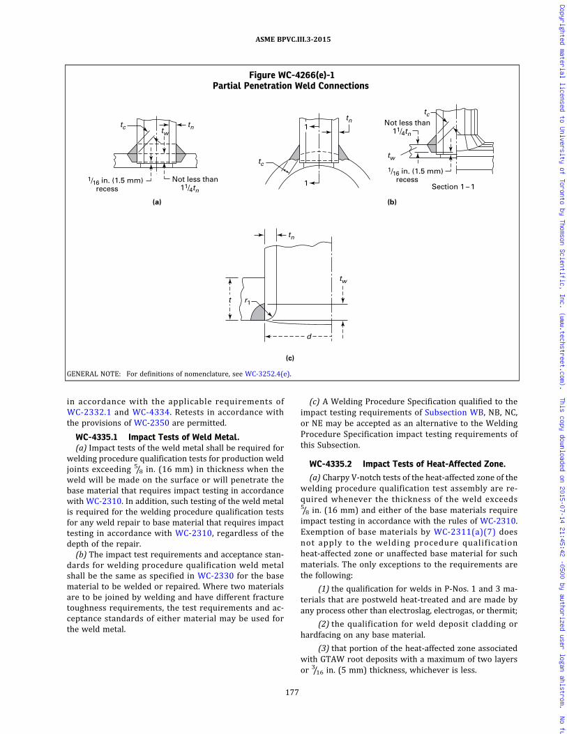
in accordance with the applicable requirements ofWC-2332.1 and WC-4334. Retests in accordance withthe provisions of WC-2350 are permitted.
WC-4335.1 Impact Tests of Weld Metal.(a) Impact tests of the weld metal shall be required for
welding procedure qualification tests for production weldjoints exceeding 5/8 in. (16 mm) in thickness when theweld will be made on the surface or will penetrate thebase material that requires impact testing in accordancewith WC-2310. In addition, such testing of the weld metalis required for the welding procedure qualification testsfor any weld repair to base material that requires impacttesting in accordance with WC-2310, regardless of thedepth of the repair.
(b) The impact test requirements and acceptance stan-dards for welding procedure qualification weld metalshall be the same as specified in WC-2330 for the basematerial to be welded or repaired. Where two materialsare to be joined by welding and have different fracturetoughness requirements, the test requirements and ac-ceptance standards of either material may be used forthe weld metal.
(c) A Welding Procedure Specification qualified to theimpact testing requirements of Subsection WB, NB, NC,or NE may be accepted as an alternative to the WeldingProcedure Specification impact testing requirements ofthis Subsection.
WC-4335.2 Impact Tests of Heat-Affected Zone.
(a) Charpy V‐notch tests of the heat‐affected zone of thewelding procedure qualification test assembly are re-quired whenever the thickness of the weld exceeds5/8 in. (16 mm) and either of the base materials requireimpact testing in accordance with the rules of WC-2310.Exemption of base materials by WC-2311(a)(7) doesnot apply to the welding procedure qualificationheat‐affected zone or unaffected base material for suchmaterials. The only exceptions to the requirements arethe following:
(1) the qualification for welds in P‐Nos. 1 and 3 ma-terials that are postweld heat-treated and are made byany process other than electroslag, electrogas, or thermit;
(2) the qualification for weld deposit cladding orhardfacing on any base material.
(3) that portion of the heat‐affected zone associatedwith GTAW root deposits with a maximum of two layersor 3/16 in. (5 mm) thickness, whichever is less.
Figure WC-4266(e)-1Partial Penetration Weld Connections
Not less than 11/4tn
Not less than 11/4tn
(a) (b)
(c)
tn
tn
t
d
tn
tw
tw
tc
tc
r1
tw
1/16 in. (1.5 mm) recess1/16 in. (1.5 mm)
recess
tc
1
1 Section 1 – 1
GENERAL NOTE: For definitions of nomenclature, see WC-3252.4(e).
177
ASME BPVC.III.3-2015
Copyrighted material licensed to University of Toronto by Thomson Scientific, Inc. (www.techstreet.com). This copy downloaded on 2015-07-14 21:45:42 -0500 by authorized user logan ahlstrom. No further reproduction or distribution is permitted.
(b) Charpy V‐notch testing shall be performed as speci-fied in (1) through (6).
(1) Charpy V‐notch test specimens representing boththe heat‐affected zone and the unaffected base materialshall be tested. The unaffected base material shall betested at a temperature equal to or below the lowest ser-vice temperature.
(2) The Charpy V‐notch tests of the unaffected basematerial shall meet the applicable requirements of TableWC-2332.1-1 or Table WC-2332.1-2, as applicable, or ad-ditional testing shall be performed at higher tempera-tures until either of the above requirements are met.
(3) The heat‐affected zone specimens shall be testedat the test temperature determined in (2). The averageapplicable toughness values of the heat‐affected zone spe-cimens shall equal or exceed the average applicabletoughness values of the unaffected base material speci-mens, or the adjustment given in (4) through (6) shallbe made. Alternatively, another test coupon may bewelded and tested.
(4) Additional Charpy V‐notch tests shall be per-formed on either the heat‐affected zone or the unaffectedbase material, or both, at temperatures where the applic-able toughness values of all three specimens tested is notless than that specified in (2). The applicable averagetoughness values for each test meeting this requirementshall be plotted on an applicable toughness value versustemperature graph. The difference in temperature THAZ
and TUBM where the heat‐affected zone and the unaf-fected base material applicable average toughness valuesare the same and not less than that specified in (2) shallbe used to determine the adjustment temperature TAD J
where:
If TADJ ≤ 0, then TADJ = 0.
(5) As an alternative to (4), if the applicable tough-ness values of the heat‐affected zone specimens is no lessthan the values specified in Table WC-2332.1-1 or TableWC-2332.1-2, as applicable, and the average of theheat-affected zone specimens is not less than 7 ft-lb(10 J) or 5 mils (0.13 mm) below the average applicabletoughness values of the unaffected base material, TAD J
may be taken as 15°F (−8°C).(6) As a second alternative to (4), if the applicable
toughness values of the heat‐affected zone specimensare no less than the values speci f ied in TableWC-2332.1-1 or Table WC-2332.1-2, as applicable, thedifference between the average applicable toughness val-ues of the heat-affected zone and the unaffected base ma-terial shall be calculated and used as described in (c)(3).
(c) At least one of the following methods shall be usedto compensate for the heat‐affected zone toughness de-crease due to the welding procedure.
(1) The lowest service temperature specified in theDesign Specification for all of the material to be weldedin production welding procedure specifications (WPS)supported by this procedure qualification record (PQR)shall be increased by the adjustment temperature TADJ .
(2) The specified testing temperature for the produc-tion material may be reduced by TADJ .
(3) The materials to be welded may be welded usingthe WPS provided they exhibit toughness values that areno less than the minimum required toughness values re-quired by WC-2300 plus the difference in the averagetoughness values established in (b)(6).(d) The Charpy V‐notch testing results shall be re-
corded on the PQR and any offsetting TADJ or increasedtoughness requirements on the production material onwhich welding is to be performed shall be noted on thePQR and WPS. More than one compensation methodmay be used on a par basis.(e) A WPS qualified to the impact testing requirements
of Subsection WB, NB, NC, or NE may be accepted as analternative to theWPS impact testing requirements of thisSubsection.
WC-4336 Qualification Requirements forBuilt-Up Weld Deposits
Built‐up weld deposits for base metal reinforcementshall be qualified in accordance with the requirementsof WC-4331 to WC-4335, inclusive.
WC-4400 RULES GOVERNING MAKING,EXAMINING, AND REPAIRINGWELDS
WC-4410 PRECAUTIONS TO BE TAKEN BEFOREWELDING
WC-4411 Identification, Storage, and Handlingof Welding Materials
Each Certificate Holder is responsible for control of thewelding electrodes and other materials that are used inthe fabricat ion and instal lat ion of components(WC-4120). Suitable identification, storage, and handlingof electrodes, flux, and other welding materials shall bemaintained. Precautions shall be taken to minimize ab-sorption of moisture by electrodes and flux.
WC-4412 Cleanliness and Protection of WeldingSurfaces
The method used to prepare the base metal shall leavethe weld preparation with reasonably smooth surfaces.The surfaces for welding shall be free of scale, rust, oil,grease, and other deleterious material. The work shallbe protected from deleterious contamination and fromrain, snow, and wind during welding. Welding shall notbe performed on wet surfaces.
178
ASME BPVC.III.3-2015
Copyrighted material licensed to University of Toronto by Thomson Scientific, Inc. (www.techstreet.com). This copy downloaded on 2015-07-14 21:45:42 -0500 by authorized user logan ahlstrom. No further reproduction or distribution is permitted.
WC-4420 RULES FOR MAKING WELDED JOINTSWC-4421 Backing Rings
Backing rings that remain in place may be used. Thematerials for backing rings shall be compatible with thebase metal, but spacer pins shall not be incorporated intothe weld.
WC-4423 Double-Welded Joints, Single-WeldedJoints, and Peening
WC-4423.1 Double-Welded Joints. Before applyingweld metal on the second side to be welded, the root offull penetration double‐welded joints shall be preparedby suitable methods such as chipping, grinding, or ther-mal gouging, except for those processes of welding bywhich proper fusion and penetrations are otherwise ob-tained and demonstrated to be satisfactory by weldingprocedure qualifications.
WC-4423.2 Single-Welded Joints. Where single-welded joints are used, particular care shall be taken inaligning and separating the items to be joined so thatthere will be complete penetration and fusion at the bot-tom of the joint for its full length.
WC-4423.3 Peening. Controlled peening may be per-formed to minimize distortion. Peening shall not be usedon the internal layer (root) of the weld metal nor on thefinal layers unless the weld is postweld heat-treated.
WC-4424 Surfaces of Welds
As‐welded surfaces are permitted. However, the sur-face of welds shall be sufficiently free from coarse ripples,grooves, overlaps, abrupt ridges, and valleys to meet therequirements of (a) through (e) below.
(a) The surface condition of the finished weld shall besuitable for the proper interpretation of radiographicand other required nondestructive examination of theweld. In those cases where there is a question regardingthe surface condition on the interpretation of a radio-graphic film, the film shall be compared to the actual weldsurface for interpretation and determination ofacceptability.
(b) Reinforcements are permitted in accordance withWC-4426.1.
(c) Undercuts shall not exceed 1/32 in. (0.8 mm) andshall not encroach on the required section thickness.
(d) Concavity on the root side of a single-welded cir-cumferential butt weld is permitted when the resultingthickness of the weld meets the requirements of ArticleWC-3000.
(e) If the surface of the weld requires grinding to meetthe above criteria, care shall be taken to avoid reducingthe weld or base material below the required thickness.
WC-4425 Welding Items of Different DiametersWhen items of different diameters are welded together,
there shall be a gradual transition between the two sur-faces. The slope of the transition shall be such that thelength–offset ratio shall not be less than 3:1, unless great-er slopes are shown to be acceptable by analysis for ves-sels designed to WC-3200. The length of the transitionmay include the weld.
WC-4426 Reinforcement of WeldsWC-4426.1 Weld Reinforcement. The surface of the
reinforcement of all butt-welded joints may be flush withthe base material or may have uniform crowns. Theheight of reinforcement on each face of the weld shallnot exceed the thicknesses in the following tabulation:
Nominal Thickness, in. (mm)
MaximumReinforcement, in.
(mm)
Up to 1 (25), incl. 3/32 (2.5)
Over 1 to 2 (25 to 50), incl. 1/8 (3)
Over 2 to 3 (50 to 75), incl. 5/32 (4)
Over 3 to 4 (75 to 100), incl. 7/32 (5.5)
Over 4 to 5 (100 to 125), incl. 1/4 (6)
Over 5 (125) 5/16 (8)
WC-4427 Shape and Size of Fillet Welds(a) Fillet welds may vary from convex to concave. Ex-
cept as permitted in (b) below, the shape and size ofthe weld shall be in accordance with the requirementsof Figure WC-4427-1. A fillet weld in any single continu-ous weld may be less than the specified fillet weld dimen-sion by not more than 1/16 in. (1.5 mm), provided that thetotal undersize portion of the weld does not exceed 10%of the length of the weld. Individual undersize weld por-tions shall not exceed 2 in. (50 mm) in length. In makingsocket welds, a gap as shown in Figure WC-4427-1 shallbe provided prior to welding. The gap need not be presentnor be verified after welding. For sleeve type joints with-out internal shoulder, the gap shall be between the but-ting ends of the pipe or tube.
(b) Socket welds smaller than those specified in FigureWC-4427-1 may be used provided the requirements ofArticle WC-3000 are met.
WC-4428 Seal Welds of Threaded JointsWhere seal welding of threaded pipe joints is per-
formed, the exposed threads shall be either removed en-tirely or covered with weld metal.
WC-4430 WELDING OF ATTACHMENTSWC-4431 Materials for Attachments
Structural attachments that are not part of the contain-ment shall be of the materials that meet the requirementsof WC-2190. Structural attachments that are part of thecontainment shall meet the requirements of WC-2120.
179
ASME BPVC.III.3-2015
Copyrighted material licensed to University of Toronto by Thomson Scientific, Inc. (www.techstreet.com). This copy downloaded on 2015-07-14 21:45:42 -0500 by authorized user logan ahlstrom. No further reproduction or distribution is permitted.

Figure WC-4427-1Fillet and Socket Weld Details and Dimensions
Theoretical throat
Surface of vertical member
Theoretical throat
Surface of vertical member
Theoretical throat
Theoretical throat
Surface of vertical member
Surface of vertical member
Convex fillet weld
Convex fillet weld
Concave fillet weld
Concave fillet weld
Size of weld
Surface of horizontal member
(b) Unequal Leg Fillet Weld [Note (2)]
Cx
Cx
(a) Equal Leg Fillet Weld [Note (1)]
Size of weld
1/16 in. (1.5 mm) approx. before welding
1/16 in. (1.5 mm) approx. before welding
(c-2) Socket Welding Fittings [Note (4)] (c-1) Socket Welding Flange [Note (3)]
tn nominal pipe wall thickness x, min.
x, min.
tn
Surface of horizontal member
(c) Minimum Welding Dimensions for Slip-On and Socket
Welding Flanges and Socket Welding Fittings
NOTES:(1) The size of an equal leg fillet weld is the leg length of the largest right isosceles triangle. Theoretical throat = 0.7 × size of weld.(2) The size of an unequal leg fillet weld is the shorter leg length of the largest right triangle that can be inscribed within the fillet weld cross
section.(3) x , min. = 1.4tn or the thickness of the hub, whichever is smaller, but not less than 1/8 in. (3 mm)(4) Cx , min. = 1.09tn where tn = nominal pipe wall thickness
180
ASME BPVC.III.3-2015
Copyrighted material licensed to University of Toronto by Thomson Scientific, Inc. (www.techstreet.com). This copy downloaded on 2015-07-14 21:45:42 -0500 by authorized user logan ahlstrom. No further reproduction or distribution is permitted.

ð15Þ
WC-4432 Welding of Structural Attachments
The rules of WC-4321 governing welding qualificationsshall apply to the welding of structural attachments tocontainment material.
WC-4433 Structural Attachments
Structural attachments shall conform reasonably to thecurvature of the surface to which they are to be attachedand shall be attached by full penetration, fillet, or partialpenetration continuous or intermittent welds. FiguresWC-4433-1 and WC-4433-2 illustrate some of the typicaldetails for attaching structural attachments to a compo-nent using full penetration welds.
WC-4434 Welding of Internal StructuralSupports to Clad Containments
Internal structural supports on clad containments shallbe welded to the base metal and not to the cladding ex-cept for weld overlay cladding.
WC-4435 Welding of Nonstructural andTemporary Attachments and TheirRemoval
(a) Nonstructural attachments welded to the contain-ment need not comply with Article WC-2000 and maybe welded with continuous or intermittent fillet or partialpenetration welds, provided the requirements of (1)through (4) below are met.
(1) The welding procedure and the welders havebeen qualified in accordance with WC-4321.
(2) The material is identified and is compatible withthe material to which it is attached.
(3) The welding material is identified and is compati-ble with the materials joined.
(4) The welds are postweld heat-treated when re-quired by WC-4620.
(b) Removal of nonstructural attachments, when tem-porary, shall be accomplished as follows:
(1) The immediate area around the temporary at-tachment is marked in a suitable manner so that after re-moval the area can be identified until after it has beenexamined in accordance with (3) below.
(2) The temporary attachment is completely re-moved in accordance with the procedures of WC-4211.
(3) After the temporary attachment has been re-moved, the marked area is examined by the liquid pene-trant or magnetic particle method in accordance withthe requirements of WC-5120 and meets the acceptancestandards of WC-5340 or WC-5350, whichever isapplicable.
(4) As an alternative to (a)(4) above, postweld heattreatment may be deferred until after removal of theattachment.
WC-4450 REPAIR OF WELD METAL DEFECTSWC-4451 General Requirements
Defects in weld metal detected by the examinations re-quired by Article WC-5000 or by the tests of ArticleWC-6000 shall be eliminated and repaired when neces-sary or the indication reduced to an acceptable limit.
WC-4452 Elimination of Surface Defects
Weld metal surface defects may be removed by grind-ing or machining and need not be repaired by welding,provided the requirements of (a), (b), and (c) below aremet.
(a) The remaining thickness of the section is not re-duced below that required by Article WC-3000.
(b) The depression, after defect elimination, is blendeduniformly into the surrounding surface.
(c) The area is examined by a magnetic particle or li-quid penetrant method in accordance with WC-5100 afterblending and meets the acceptance standards ofWC-5300 to ensure that the defect has been removed orthe indication reduced to an acceptable limit. Defects de-tected by visual or volumetric method and located on aninterior surface need only be reexamined by the methodwhich initially detected the defect when the interior sur-face is inaccessible for surface examination.
WC-4453 Requirements for Making Repairs ofWelds
Excavations in weld metal, when repaired by welding,sha l l meet the requ i rements o f the fo l lowingsubparagraphs.
WC-4453.1 Defect Removal. Defects may be re-moved by mechanical means or by thermal gouging pro-cesses. The area prepared for repair shall be examinedby a liquid penetrant or magnetic particle method in ac-cordance with WC-5100 and meet the acceptance stan-dards of WC-5340 or WC-5350. This examination is notrequired where defect elimination removes the full thick-ness of the weld and where the backside of the weld jointis not accessible for removal of examination materials.
WC-4453.2 Requirements for Welding Materials,Procedures, and Welders. The weld repair shall be madeusing welding materials, welders, and welding proce-dures qualified in accordance with WC-4125 andWC-4300.
WC-4453.3 Blending of Repaired Areas. After repairthe surface shall be blended uniformly into the surround-ing surface.
WC-4453.4 Examination of Repair Welds.(a) The examination of a weld repair shall be repeated
as required for the original weld, except that it need onlybe reexamined by the liquid penetrant or magnetic parti-cle method when the unacceptable indication was
181
ASME BPVC.III.3-2015
Copyrighted material licensed to University of Toronto by Thomson Scientific, Inc. (www.techstreet.com). This copy downloaded on 2015-07-14 21:45:42 -0500 by authorized user logan ahlstrom. No further reproduction or distribution is permitted.

Figure WC-4433-1Typical Types of Attachment Welds
1/8 in. (3 mm), max.
1/8 in. (3 mm), max.
(c) Attachment of Rings
(b) Attachment of Trunnions
A
A
(a) Attachment of Lugs, Shoes, Pipe Saddles, and Brackets
Dimension not sufficient for weld from inside
Section A-A 1/8 in. (3 mm), max.
Section A-A
A Section A-A 1/8 in. (3 mm), max.
A
A
A
GENERAL NOTE: The welds may be partial penetration or fillet welds.
182
ASME BPVC.III.3-2015
Copyrighted material licensed to University of Toronto by Thomson Scientific, Inc. (www.techstreet.com). This copy downloaded on 2015-07-14 21:45:42 -0500 by authorized user logan ahlstrom. No further reproduction or distribution is permitted.

originally detected by the liquid penetrant or magneticparticle method and when the repair cavity does not ex-ceed the following:
(1) 1/3t for t ≤ 3/4 in. (19 mm)(2) 1/4 in. (6 mm) for 3/4 in. (19 mm) < t ≤ 21/2 in.
(64 mm)(3) the lesser of 3/8 in. (10 mm) or 10%t for t > 21/2 in.
(64 mm) where t equals the thickness of the weld.(b)When repairs to welds joining P‐No. 1 and P‐No. 3
materials require examination by radiography as re-quired in (a) above, but construction assembly preventsmeaningful radiographic examination, ultrasonic exami-nation may be substituted, provided that:
(1) the weld has been previously radiographed andmet the applicable acceptance standards;
(2) the ultrasonic examination is performed using aprocedure in accordance with Section V, Article 4 to theacceptance standards of WC-5330;
(3) the substitution is limited to Category A and Bwelds in containments and similar type welds in otheritems.
The absence of suitable radiographic equipment isnot justification for the substitution.
WC-4453.5 Heat Treatment of Repaired Areas. Thearea shall be heat-treated in accordance with WC-4620.
WC-4500 BRAZING
WC-4510 RULES FOR BRAZING
WC-4511 Where Brazing May Be Used
Brazing is permitted for nonstructural attachmentsonly.
WC-4512 Brazing Material
Where brazing is permitted, the brazing filler materialand fluxes shall conform to the rules covering identifica-tion in WC-2150 and to the requirements of (a), (b),and (c) below.
(a) The filler material used in brazing shall be a nonfer-rous metal or alloy with a solidus temperature above800°F (425°C) and at least 500°F (280°C) above the high-est temperature of the joint in service.
(b) The filler material shall melt and flow freely by ca-pillary action within the desired temperature range, andin conjunction with a suitable flux or controlled atmo-sphere the filler material shall wet and adhere to the sur-faces to be joined.
(c) Fluxes that are fluid and chemically active at thebrazing temperature shall be used, when necessary, toprevent oxidation of the filler metal and the surfaces tobe joined, and to promote free flowing of the fillermaterial.
Figure WC-4433-2Typical Attachments
GENERAL NOTES:(a) a ≥ t/4; b ≥ t/2; c ≥ t
t = thickness of attached memberc = minimum thickness of weld metal from the root to the face of the weld
(b) All welds continuous.
183
ASME BPVC.III.3-2015
Copyrighted material licensed to University of Toronto by Thomson Scientific, Inc. (www.techstreet.com). This copy downloaded on 2015-07-14 21:45:42 -0500 by authorized user logan ahlstrom. No further reproduction or distribution is permitted.

WC-4520 BRAZING QUALIFICATIONREQUIREMENTS
WC-4521 Brazing Procedure and PerformanceQualification
Qualification of the brazing procedure to be used and ofthe performance of brazers and brazing operators is re-quired and shall comply with the requirements of SectionIX, except as noted below.
WC-4523 Reheated Joints
In addition to the requirements of Section IX, the braz-ing procedure shall be set up as a new procedure specifi-cation and shall be completely requalified when theconstruction of the brazed components includes reheat-ing of any portion of the completed brazed joint to a tem-perature that is within 300°F (170°C) of the solidustemperature of the filler metal.
WC-4524 Maximum Temperature Limits
The Design Temperature shall not exceed the uppertemperature shown in the third column of TableWC-4524-1. For Design Temperatures below the tem-perature shown in the second column of TableWC-4524-1, no further testing beyond that required bySection IX is required. For Design Temperatures in therange shown in the third column of Table WC-4524-1,tests in addition to those required by Section IX are re-quired. These tests shall be considered a part of the pro-cedure qualification. For such Design Temperatures, twotension tests on production type joints are required,one at the Design Temperature and one at 1.05T [whereT is the Design Temperature in °F (°C)]. Neither of theseproduction‐type joints shall fail in the braze metal.
WC-4530 FITTING AND ALIGNING OF PARTS TOBE BRAZED
Parts to be joined by brazing shall be fitted, and re-tained in position during the brazing operation withinthe tolerances specified in the brazing procedure
specification. Brazed joints shall be assembled in a se-quence which will permit the maximum number of jointsto be visually examined on both sides of the joint afterbrazing.
WC-4540 EXAMINATION OF BRAZED JOINTS
The completed brazed joints shall be visually examinedon all accessible surfaces in accordance with WC-5275.
WC-4600 HEAT TREATMENT
WC-4610 WELDING PREHEAT REQUIREMENTSWC-4611 When Preheat Is Necessary
The need for and temperature of preheat are depen-dent on a number of factors, such as the chemical analysis,degree of restraint of the parts being joined, elevated tem-perature, physical properties, and material thicknesses.Some practices used for preheating are given in SectionIII Appendices, Nonmandatory Appendix D as a generalguide for the materials listed by P‐Number of Section IX.It is cautioned that the preheating suggested in SectionIII Appendices, Nonmandatory Appendix D does not ne-cessarily ensure satisfactory completion of the weldedjoint and that the preheating requirements for individualmaterials within the P‐Number listing may be more orless restrictive. The welding procedure specification forthe material being welded shall specify the minimum pre-heating requirements under the welding procedure quali-fication requirements of Section IX.
WC-4612 Preheating Methods
Preheat for welding or thermal cutting, when em-ployed, may be applied by any method which does notharm the base material or any weld metal already appliedor which does not introduce deleterious material into thewelding area which is harmful to the weld.
Table WC-4524-1Maximum Design Temperatures for Brazing Filler Metal, °F (°C)
Filler MetalClassification
Temperature BelowWhich Section IX TestsOnly Are Required
Temperature Range RequiringSection IX Tests and Additional
Tests
BCuP 300 (150) 300–350 (150–175)BAg 400 (205) 400–500 (205–260)BCuZn 400 (205) 400–500 (205–260)
BCu 400 (205) 400–650 (205–345)BAISi 300 (150) 300–350 (150–175)BNi 800 (425) …
GENERAL NOTE: Temperatures are based on AWS recommendations.
184
ASME BPVC.III.3-2015
Copyrighted material licensed to University of Toronto by Thomson Scientific, Inc. (www.techstreet.com). This copy downloaded on 2015-07-14 21:45:42 -0500 by authorized user logan ahlstrom. No further reproduction or distribution is permitted.

WC-4613 Interpass Temperature
Consideration must be given to the limitations of inter-pass temperatures for quenched and tempered materialsto avoid detrimental effects on the mechanical properties.
WC-4620 POSTWELD HEAT TREATMENTWC-4621 Heating and Cooling Methods
Postweld heat treatment (PWHT) may be accomplishedby any suitable methods of heating and cooling, providedthe required heating and cooling rates, metal tempera-ture, metal temperature uniformity, and temperaturecontrol are maintained.
WC-4622 PWHT Time and TemperatureRequirements
WC-4622.1 General Requirements.8 Except as other-wise permitted in WC-4622.7, all welds, including repairwelds, shall be postweld heat-treated. During postweldheat treatment, the metal temperature shall be main-tained within the temperature ranges for the minimumholding time specified in Table WC-4622.1-1 except asotherwise permitted in WC-4622.4(c). P‐Number groupsin Table WC-4622.1-1 are in accordance with Section IX,QW‐420. Except as provided in WC-4624.3, PWHT shallbe performed in temperature‐surveyed and ‐calibratedfurnaces, or PWHT shall be performed with thermocou-ples in contact with the material or attached to blocksin contact with the material. In addition, the requirementsof the following subparagraphs shall apply.
WC-4622.2 Time–Temperature Recordings. Time-temperature recordings of all postweld heat treatmentsshall be made available for review by the Inspector. Iden-tification on the time–temperature recording shall be to
the weld, part, or component. A summary of the time–temperature recording may be provided for permanentrecords in accordance with WA-4134.
WC-4622.3 Definition of Nominal Thickness Gov-e r n i n g P W H T . Nom i n a l t h i c k n e s s i n T a b l eWC-4622.7(b)-1 is the thickness of the weld, the contain-ment material for structural attachment welds or thethinner of the containment materials being joined, which-ever is least. It is not intended that nominal thickness in-clude material provided for forming allowance, thinning,or mill overrun when the excess material does not exceed1/8 in. (3 mm). For fillet welds the nominal thickness is thethroat thickness, and for partial penetration and materialrepair welds the nominal thickness is the depth of theweld groove or preparation.
WC-4622.4 Holding Times at Temperature.(a) The holding time at temperature as specified in
Table WC-4622.1-1 shall be based on the nominal thick-ness of the weld. The holding time need not be continu-ous. It may be an accumulation of the times of multiplepostweld heat‐treat cycles.
(b) Holding time at temperature in excess of the mini-mum requirements of Table WC-4622.1-1 may be used,provided that specimens so heat-treated are tested in ac-cordance with WC-2200, WC-2400, and WC-4300.
(c) Alternatively, when it is impractical to postweldheat treat at the temperature range specified in TableWC-4622.1-1, it is permissible to perform the postweldheat treatment of certain materials at lower temperaturesfor longer periods of time in accordance with TableWC-4622.4(c)-1 and (1), (2), and (3) below.
(1) Except for P‐No. 1 materials, when welds in thematerials listed in Table WC-4622.4(c)-1 are to be post-weld heat-treated at the lower minimum temperatures,
Table WC-4622.1-1Mandatory Requirements for Postweld Heat Treatment of Welds
P‐No. (Sec. IX, QW-420)
HoldingTemperatureRange, °F (°C)
[Note (1)]
Minimum Holding Time at Temperature for Weld Thickness (Nominal)
1/2 in. (13 mm)or less
Over 1/2 in. to 2 in.(13 mm to 50 mm)
Over 2 in. to 5 in.(50 mm to 125 mm) Over 5 in. (125 mm)
1, 31,100–1,250(595–675)
30 min 1 hr/in. (2 min/mm)
2 hr plus 15 min eachadditional inch (2 hplus 0.5 min/mm)over 2 in. (50 mm)
2 hr plus 15 min eachadditional inch (2 hplus 0.5 min/mm)over 2 in. (50 mm)
P‐Nos. 8, 10H Gr. 1, 34, 42,43, 45 and hard surfacingon P‐No. 1 base metalwhose reported carboncontent is not more than0.30%
PWHT neither required nor prohibited
GENERAL NOTE: Exemptions to the mandatory requirements of this Table are defined in WC-4622.7.
NOTE:(1) All temperatures are metal temperatures.
185
ASME BPVC.III.3-2015
Copyrighted material licensed to University of Toronto by Thomson Scientific, Inc. (www.techstreet.com). This copy downloaded on 2015-07-14 21:45:42 -0500 by authorized user logan ahlstrom. No further reproduction or distribution is permitted.

the impact test specimens for the welding procedure qua-lification required by WC-4300 shall be made using thesame minimum temperatures and increased minimumholding time. Welding procedures, qualified at the tem-perature range and minimum holding time specified inTable WC-4622.1-1 and at the lower temperature and in-creased minimum holding time permitted by TableWC-4622.4(c)-1, are also qualified for any temperaturein between. When such an in‐between temperature isused, the minimum holding time shall be interpolatedfrom Table WC-4622.1-1 and the alternative require-ments from Table WC-4622.4(c)-1.
(2) Except for P‐No. 1 materials, when welds in thematerials listed in Table WC-4622.4(c)-1 are to be post-weld heat-treated at these lower minimum temperatures,the welding material certification required by WC-2400shall be made using the same minimum temperatureand increased minimum holding time. Welding materialcertified at the temperature range and minimum holdingtime specified in Table WC-4622.1-1 and at the lowerminimum temperatures and increased minimum holdingtime permitted by Table WC-4622.4(c)-1 are also certi-fied for any temperature in between.
(3) Base materials certified in accordance withWC-2200 may be postweld heat-treated at these lowerminimum temperatures and increased minimum holdingtimes without recertification. Postweld heat treatmentat these lower minimum temperatures and increasedminimum holding times may also be the tempering opera-tion, provided a higher tempering temperature is not re-quired by the material specification.
WC-4622.5 PWHT Requirements When DifferentP-Number Materials Are Joined. When containment ma-terials of two different P‐Number groups are joined bywelding, the applicable postweld heat treatment shall bethat specified in Table WC-4622.1-1 for the material re-quiring the higher PWHT temperature range.
WC-4622.6 PWHT Requirements for Noncontain-ment Parts. When parts not performing a containmentfunction are welded to contaiment materials, the post-weld heat treatment temperature range of the contain-ment materials shall control.
WC-4622.7 Exemptions to Mandatory Require-ments. Postweld heat treatment in accordance with thissubarticle is not required for (a) through (g) below:(a) nonferrous materials;(b) welds exempted in Table WC-4622.7(b)-1;(c) welds subjected to temperatures above the PWHT
temperature range specified in Table WC-4622.1-1, pro-vided the Welding Procedure Specification is qualifiedin accordance with Section IX and the base material andthe deposited weld material have been heat-treated atthe higher temperature;(d) welds connecting nozzles to containments provided
the requirements in WC-4622.8 are met;(e) weld repairs to P‐No. 1 or P‐No. 3 materials in con-
tainments, provided the requirements of WC-4622.9 orWC-4622.10 are met;(f) weld repairs to cladding after final postweld heat
treatment provided the requirements of WC-4622.11are met;(g) weld repairs to dissimilar metal welds after final
postweld heat treatment provided the requirements ofWC-4622.12 are met.
WC-4622.8 Requirements for Exempting PWHT ofNozzles to Containment Welds. Welds connecting noz-zles of P‐No. 1 materials to containments of P‐No. 1 orP‐No. 3 materials that are not exempted from PWHT inTable WC-4622.7(b)-1 need not be given a postweld heattreatment if the requirements of (a) are met for partialpenetration and (b) are met for full penetration welds.(a) The partial penetration welds are made with A‐No.
8 or non‐air‐hardening nickel–chromium–iron weld me-tal after:
(1) the ferritic materials to be joined are buttered orbuildup with A‐No. 8 or non‐air‐hardening nickel–chromium–iron weld metal having a minimum thicknessof 1/4 in. (6 mm); and
(2) the heat affected zones of the buttered or buildupferritic materials are postweld heat-treated in accordancewith WC-4620, without the PWHT exemptions being ap-plied, prior to making the final welds.(b) The full penetration welds are made with A‐No. 1 or
A‐No. 2 weld metal, provided that:(1) the containment is built up or buttered in the
area of the attachment with A‐No. 1 or A‐No. 2 metal hav-ing a minimum thickness of 1/4 in. (6 mm);
(2) the A‐No. 1 or A‐No. 2 weld metal buildup or but-tering is postweld heat-treated in accordance withWC-4620 for P‐No. 1 or P‐No. 3 materials without thePWHT exemptions being applied;
Table WC-4622.4(c)-1Alternative Holding Temperatures and Times
MaterialP‐Numbers
Alternative MinimumHolding Temperatures,
°F (°C)Alternative Minimum
Holding Times
1, 3 1,050 (565) 2 hr/in. (4 min/mm) thick1, 3 1,000 (540) 4 hr/in. (8 min/mm) thick
GENERAL NOTE: All other requirements of WC-4622 shall apply.
186
ASME BPVC.III.3-2015
Copyrighted material licensed to University of Toronto by Thomson Scientific, Inc. (www.techstreet.com). This copy downloaded on 2015-07-14 21:45:42 -0500 by authorized user logan ahlstrom. No further reproduction or distribution is permitted.
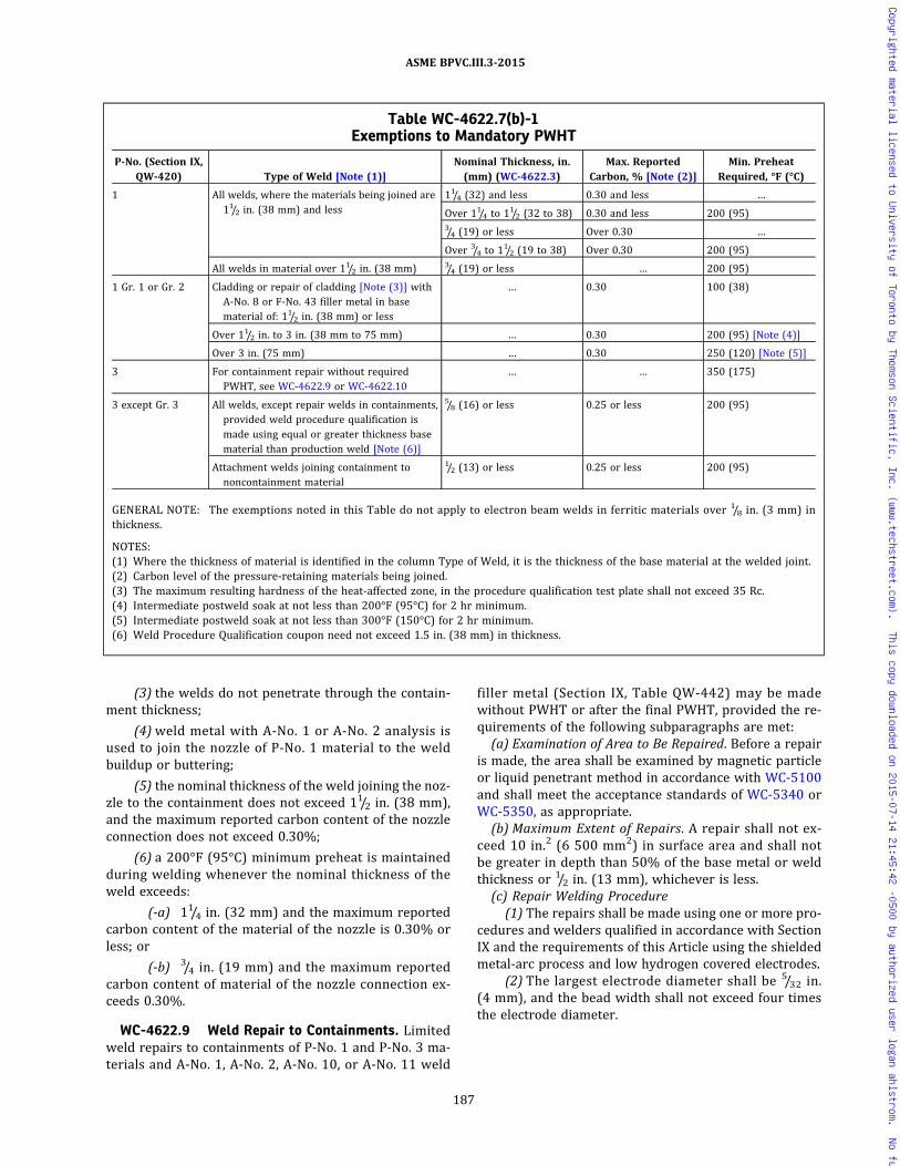
(3) the welds do not penetrate through the contain-ment thickness;
(4)weld metal with A‐No. 1 or A‐No. 2 analysis isused to join the nozzle of P‐No. 1 material to the weldbuildup or buttering;
(5) the nominal thickness of the weld joining the noz-zle to the containment does not exceed 11/2 in. (38 mm),and the maximum reported carbon content of the nozzleconnection does not exceed 0.30%;
(6) a 200°F (95°C) minimum preheat is maintainedduring welding whenever the nominal thickness of theweld exceeds:
(-a) 11/4 in. (32 mm) and the maximum reportedcarbon content of the material of the nozzle is 0.30% orless; or
(-b) 3/4 in. (19 mm) and the maximum reportedcarbon content of material of the nozzle connection ex-ceeds 0.30%.
WC-4622.9 Weld Repair to Containments. Limitedweld repairs to containments of P‐No. 1 and P‐No. 3 ma-terials and A‐No. 1, A‐No. 2, A‐No. 10, or A‐No. 11 weld
filler metal (Section IX, Table QW-442) may be madewithout PWHT or after the final PWHT, provided the re-quirements of the following subparagraphs are met:
(a) Examination of Area to Be Repaired. Before a repairis made, the area shall be examined by magnetic particleor liquid penetrant method in accordance with WC-5100and shall meet the acceptance standards of WC-5340 orWC-5350, as appropriate.
(b) Maximum Extent of Repairs. A repair shall not ex-ceed 10 in.2 (6 500 mm2) in surface area and shall notbe greater in depth than 50% of the base metal or weldthickness or 1/2 in. (13 mm), whichever is less.
(c) Repair Welding Procedure(1) The repairs shall be made using one or more pro-
cedures and welders qualified in accordance with SectionIX and the requirements of this Article using the shieldedmetal‐arc process and low hydrogen covered electrodes.
(2) The largest electrode diameter shall be 5/32 in.(4 mm), and the bead width shall not exceed four timesthe electrode diameter.
Table WC-4622.7(b)-1Exemptions to Mandatory PWHT
P‐No. (Section IX,QW‐420) Type of Weld [Note (1)]
Nominal Thickness, in.(mm) (WC-4622.3)
Max. ReportedCarbon, % [Note (2)]
Min. PreheatRequired, °F (°C)
1 All welds, where the materials being joined are11/2 in. (38 mm) and less
11/4 (32) and less 0.30 and less …
Over 11/4 to 11/2 (32 to 38) 0.30 and less 200 (95)3/4 (19) or less Over 0.30 …
Over 3/4 to 11/2 (19 to 38) Over 0.30 200 (95)
All welds in material over 11/2 in. (38 mm) 3/4 (19) or less … 200 (95)
1 Gr. 1 or Gr. 2 Cladding or repair of cladding [Note (3)] withA‐No. 8 or F‐No. 43 filler metal in basematerial of: 11/2 in. (38 mm) or less
… 0.30 100 (38)
Over 11/2 in. to 3 in. (38 mm to 75 mm) … 0.30 200 (95) [Note (4)]
Over 3 in. (75 mm) … 0.30 250 (120) [Note (5)]
3 For containment repair without requiredPWHT, see WC-4622.9 or WC-4622.10
… … 350 (175)
3 except Gr. 3 All welds, except repair welds in containments,provided weld procedure qualification ismade using equal or greater thickness basematerial than production weld [Note (6)]
5/8 (16) or less 0.25 or less 200 (95)
Attachment welds joining containment tononcontainment material
1/2 (13) or less 0.25 or less 200 (95)
GENERAL NOTE: The exemptions noted in this Table do not apply to electron beam welds in ferritic materials over 1/8 in. (3 mm) inthickness.
NOTES:(1) Where the thickness of material is identified in the column Type of Weld, it is the thickness of the base material at the welded joint.(2) Carbon level of the pressure-retaining materials being joined.(3) The maximum resulting hardness of the heat-affected zone, in the procedure qualification test plate shall not exceed 35 Rc.(4) Intermediate postweld soak at not less than 200°F (95°C) for 2 hr minimum.(5) Intermediate postweld soak at not less than 300°F (150°C) for 2 hr minimum.(6) Weld Procedure Qualification coupon need not exceed 1.5 in. (38 mm) in thickness.
187
ASME BPVC.III.3-2015
Copyrighted material licensed to University of Toronto by Thomson Scientific, Inc. (www.techstreet.com). This copy downloaded on 2015-07-14 21:45:42 -0500 by authorized user logan ahlstrom. No further reproduction or distribution is permitted.

(3) The repair weld shall be made with a minimum oftwo layers of weld metal. The last layer shall be limited orground off so that the weld surface does not extend abovethe base metal a greater distance than that allowed for re-inforcement of butt welds.
(4) A preheat and interpass temperature of 300°F(150°C) minimum shall be used.
(d) Examination of Repair Welds. Following the repairand when the area has reached ambient temperature,the area shall again be examined by magnetic particlemethods and accepted in accordance with (a) above.
WC-4622.10 Temper Bead Technique. Limited weldrepairs to P‐No. 1 and P‐No. 3 material, and A‐Nos. 1, 2,10, or 11 weld filler metal (Section IX, Table QW-442),may be made without PWHT or after the final PWHT, pro-vided it is impossible or impractical to postweld heattreat the area after repair, and provided the requirementsof the following subparagraphs are met:
(a) Examination of Area to Be Repaired. Before repair,the area shall be examined by either the magnetic particleor liquid penetrant method in accordance with ArticleWC-5000.
(b) Maximum Extent of Repair. The maximum area of anindividual repair based on the finished surface shall be100 in.2 (65 000 mm2) and the depth of repair shall notbe greater than one‐third of the base material thickness.
(c) Repair Welding Procedure. The welding procedureshall be in accordance with Section IX and this Subsectionand shall include the requirements of (1) through (8)below.
(1) The area to be repaired shall be suitably preparedfor welding in accordance with a written procedure.
(2) The weld metal shall be deposited by the manualshielded metal arc process using low hydrogen type elec-trode. The maximum bead width shall be four times theelectrode core diameter.
(3)Welding electrodes shall meet the requirementsfor supplemental des ignators “R ” indicat ing amoisture‐resistant coating and “H4” indicating that theyare low in diffusible hydrogen as defined in the applicablespecifications in Section II, Part C. Welding electrodesshall also be supplied in unopened hermetically sealedcontainers.
(4) After a hermetically sealed container is opened,the electrodes shall be stored in holding ovens at 225°Fto 350°F (105°C to 175°C). When electrodes are removedfrom elevated storage, they may be exposed to the atmo-sphere for a maximum of 8 hr.
(5) Electrodes, which are exposed to the atmospherefor more than 8 hr, shall be discarded or baked to removeany absorbed moisture for the time and temperature rec-ommended by the electrode manufacturer. After bakingand before the electrodes are allowed to cool below225°F (105°C), they shall be transferred immediately intoholding ovens at 225°F to 350°F (105°C to 175°C). When
the once‐baked electrodes are removed from elevatedstorage, they may be exposed to the atmosphere for anadditional 8 hr after which they shall be discarded.
(6) The weld area plus a band around the repair areaof at least 11/2 times the containment thickness or 5 in.(125mm), whichever is less, shall be preheated andmain-tained at a minimum temperature of 350°F (175°C) dur-ing welding. The maximum interpass temperature shallbe 450°F (230°C). Thermocouples and recording instru-ments shall be used to monitor the process temperatures.Their removal shall be in accordance with WC-4435(b).
(7) The cavity shall be buttered, using a 3/32 in.(2.5 mm) diameter electrode as shown in FigureWC-4622.10(c)(7)-1. The weld bead crown surface shallbe removed by grinding or machining before depositingthe second layer [see Figure WC-4622.10(c)(7)-1, Step2]. The second layer shall be deposited with a 1/8 in.(3 mm) diameter electrode. Subsequent layers shall bedeposited with a welding electrode no larger than5/32 in. (4 mm) diameter. Bead deposition shall be per-f o r m e d i n a m a n n e r s h o w n i n F i g u r eWC-4622.10(c)(7)-1, Step 3. The completed weld shallhave at least one layer of weld reinforcement depositedand then this reinforcement shall be removed by mechan-cial means, making the finished surface of the repair sub-stantially flush with the surface of the vessel surroundingthe repair [Figure WC-4622.10(c)(7)-2]. The techniquedescribed in this paragraph shall be performed in the pro-cedure qualification test.
(8) The weld area shall be maintained at a tempera-ture of 450°F to 550°F (230°C to 290°C) for a minimumperiod of 2 hr after completion of the weld repair inP‐No. 1 materials. For P‐No. 3 materials, the holding timeshall be a minimum of 4 hr.(d) Examination of Repair Welds. The second (temper
bead) layer shall be examined by the magnetic particleor liquid penetrant method. The completed weld shallhave the weld reinforcement, including the final layer, re-moved substantially flush with the surface prior to per-forming the required nondestructive examination. Thenondestructive examination shall be performed after thecompleted weld has been at ambient temperature for aminimum period of 48 hr to detect the presence of possi-ble delayed cracking of the weldment. The nondestructiveexamination of the repair welded and preheated regionshall be in accordance with WC-4453.4. In addition, all re-pairs shall be ultrasonically examined. All nondestructiveexamination shall be in accordance with Article WC-5000.(e) Documentation of Weld Repairs. Documentation of
weld repairs shall be in accordance with WC-4130, exclu-sive of the size requirements.(f) Welding Procedure Qualification Test Plate. The test
assembly materials for the welding procedure qualifica-tion shall be of the same P‐Number and Group Number,including a postweld heat treatment that is at leastequivalent to the time and temperature applied to the ma-terials being repaired. The depth of cavity in the test
188
ASME BPVC.III.3-2015
Copyrighted material licensed to University of Toronto by Thomson Scientific, Inc. (www.techstreet.com). This copy downloaded on 2015-07-14 21:45:42 -0500 by authorized user logan ahlstrom. No further reproduction or distribution is permitted.
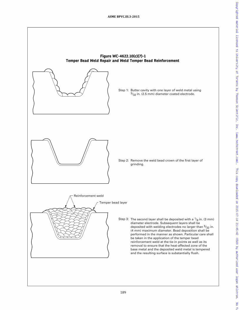
Figure WC-4622.10(c)(7)-1Temper Bead Weld Repair and Weld Temper Bead Reinforcement
Reinforcement weld
Temper bead layer
Step 3:
Step 2: Remove the weld bead crown of the first layer ofgrinding.
Step 1: Butter cavity with one layer of weld metal using 3/32 in. (2.5 mm) diameter coated electrode.
The second layer shall be deposited with a 1/8 in. (3 mm) diameter electrode. Subsequent layers shall be deposited with welding electrodes no larger than 5/32 in. (4 mm) maximum diameter. Bead deposition shall be performed in the manner as shown. Particular care shall be taken in the application of the temper bead reinforcement weld at the tie-in points as well as its removal to ensure that the heat-affected zone of the base metal and the deposited weld metal is tempered and the resulting surface is substantially flush.
189
ASME BPVC.III.3-2015
Copyrighted material licensed to University of Toronto by Thomson Scientific, Inc. (www.techstreet.com). This copy downloaded on 2015-07-14 21:45:42 -0500 by authorized user logan ahlstrom. No further reproduction or distribution is permitted.

assembly shall be a minimum of one‐half the depth of ac-tual repair, but not less than 1 in. (25 mm). The test as-sembly thickness shall be a minimum of twice the depthof cavity in the test assembly. The test assembly shallbe large enough to permit removal of the required testspecimens. In order to simulate the restraint that theweld metal will experience in the repair section of thecomponent, the test assembly dimensions surroundingthe cavity shall be equal to the test assembly thickness,but not less than 6 in. (150 mm). The qualification testplate shall be prepared in accordance with FigureWC-4622.10(f)-1.(g) This test assembly may be used to qualify proce-
dures for weld buildup repairs of pressure-retaining ma-terials. In this case, the depth of the cavity shall not be lessthan the thickness of the weld buildup or 1 in. (25 mm),whichever is greater, and the area of the weld buildupto be applied or 54 in.2 (35 000 mm2), whichever is less.(h) In all cases, the test assembly and cavity shall be of
sufficient size to permit removal of the required testspecimens.(i) Performance Qualifications. If the repair weld is to
be performed where physical obstructions impair thewelder’s ability to perform, the welder shall also demon-strate the ability to deposit sound weld metal in the posi-tions required, using the same parameters and simulatedphysical obstructions as are involved in the repair.
WC-4622.11 Repair Welds to Cladding After FinalPostweld Heat Treatment. Nonpostweld heat-treatedweld repairs may be made to P‐No. 8 or P‐No. 43 claddingof P‐No. 1 and P‐No. 3 material after final PWHT, providedit is impossible or impractical to postweld heat treat thearea after repair, and provided the requirements of thefollowing subparagraphs are met:(a) Maximum Extent of Repair. This procedure may be
used with the base material exposed to a depth not great-er than 1/4 in. (6 mm) or 10% of the base material thick-ness, whichever is less, nor to an individual area greaterthan 100 in.2 (65 000 mm2). Areas with greater base ma-terial exposure depth shall be repaired in accordancewith WC-4622.10 to within this limit before implement-ing the cladding repair.
(b) Repair Welding Procedure. The welding procedureshall be in accordance with Section IX and this Article,and shall include the requirements of (1) through (7)below.
(1) The repairs shall be made using A‐No. 8 weld me-tal (Section IX, Table QW-442) for P‐No. 8 cladding orF‐No. 43 weld metal (Section IX, Table QW-432) for eitherP‐No. 8 or P‐No. 43 cladding.
(2) The manual shielded metal arc process shall beused for welding with a bead width not to exceed fourtimes the electrode core diameter.
(3) All covered electrodes used for qualification testand repair welding shall be from unopened, hermeticallysealed packages or heated ovens maintained between225°F (105°C) and 350°F (175°C). Electrodes withdrawnfrom hermetically sealed containers or ovens for longerthan 8 hr shall be discarded, or baked once at the timeand temperature recommended by the electrode manu-facturer and placed immediately back into the holdingovens. Electrodes exposed to the atmosphere for morethan 8 hr after once being baked shall be discarded.
(4) During the repair, the electrodes may be main-tained in heated ovens in the repair area. The oven tem-perature shall be maintained between 225°F (105°C)and 350°F (175°C). Electrodes exposed to the atmospherefor more than 8 hr shall be discarded, or baked once atthe time and temperature recommended by the electrodemanufacturer and placed immediately back into the hold-ing ovens. Electrodes exposed to the atmosphere for morethan 8 hr after once being baked shall be discarded.
(5) The weld area plus a band around the clad repairof 11/2 times the component thickness or 5 in. (125 mm),whichever is less, shall be preheated and maintained at aminimum temperature of 350°F (175°C) during welding.The maximum interpass temperature shall be 450°F(230°C). Thermocouples and recording instruments shallbe used to monitor the process temperatures. Their re-moval shall be in accordance with WC-4435.
(6) All areas of the base material on which weld me-tal is to be deposited shall be covered with a single layerof weld deposit using 3/32 in. (2.5 mm) diameter electrode,followed by a minimum of one layer of weld deposit using1/8 in. (3 mm) diameter electrode. Subsequent layers maybe deposited with electrode no larger than 5/32 in. (4 mm).The weld bead crown surface of the first layer shall be re-moved by grinding.
(7) After completion of welding, the weld area shallbe maintained at a temperature of 450°F to 550°F(230°C to 290°C) for a period of 2 hr for P‐No. 1 materialand 4 hr for P‐No. 3 material.(c) Examination of Repair Welds. The weld repair as
well as the preheated band shall be examined by the li-quid penetrant method. All nondestructive examinationshall be in accordance with Article WC-5000.(d) Documentation of Weld Repairs. Documentation of
weld repairs shall be in accordance with WC-4130, exclu-sive of the size requirements.
Figure WC-4622.10(c)(7)-2Temper Bead Reinforcement
NOTE:(1) Apply temper bead reinforcement weld metal to a level above
the surface and then remove it substantially flush to the surfaceas required by WC-4622.10(c)(7).
190
ASME BPVC.III.3-2015
Copyrighted material licensed to University of Toronto by Thomson Scientific, Inc. (www.techstreet.com). This copy downloaded on 2015-07-14 21:45:42 -0500 by authorized user logan ahlstrom. No further reproduction or distribution is permitted.

ð15ÞFigure WC-4622.10(f)-1Qualification Test Plate
Reduced section
Side bend
Side bend
Reduced section
Side bend
Side bend
Discard
specimen
specimen
specimen
specimen
specimen
specimen
Charpy
Charpy
Charpy
V – Notch (HAZ)
V – Notch (HAZ)
Charpy V – Notch (HAZ)
1/8 in. 1/32 in. (3 mm 0.8 mm)Fusion line
30 deg (max.)
Weld metal
Heat-affected zone
3/8 in. (10 mm)WC-4622.10(f)Elevation
view
Plan
view
1/2 in. (13 mm) min.
V – Notch (HAZ)
191
ASME BPVC.III.3-2015
Copyrighted material licensed to University of Toronto by Thomson Scientific, Inc. (www.techstreet.com). This copy downloaded on 2015-07-14 21:45:42 -0500 by authorized user logan ahlstrom. No further reproduction or distribution is permitted.
(e) Welding Procedure Qualification Test Plate(1) The test assembly material for the welding proce-
dure qualification test shall be of the same P‐Number andGroup Number, including a postweld heat treatment thatis at least equivalent to the time and temperature of thatapplied to the material being repaired. If the repair in-volves two different P‐Number or Group Number materi-als, the test assembly shall duplicate the combination.
(2) The test assembly base material shall be at least12 in. (300 mm) by 12 in. (300 mm), 2 in. (50 mm)min. thickness, with a clad surface area of at least 8 in.(200 mm) by 8 in. (200 mm), in the area from whichthe bend test specimens will be removed.
(3) The qualification test plate assembly shall be pre-pared and tested in accordance with the requirements ofSection IX. The guided bend test acceptance standards de-scribed in Section IX for cladding shall also be applicableto the HAZ of the base material.(f) Performance Qualifications. If the repair weld is to
be performed where physical obstructions impair thewelder’s ability to perform, the welder shall also demon-strate the ability to deposit sound weld metal in the posi-tions required, using the same parameters and simulatedphysical obstructions as are involved in the repair.
WC-4622.12 Temper Bead Weld Repair to DissimilarMetal Welds or Buttering. Whenever PWHT is impracti-cal or impossible, limited weld repairs to dissimilar metalwelds of P‐No. 1 and P‐No. 3 material or weld filler metalA‐No. 8 (Section IX, Table QW-442) or F‐No. 43 (SectionIX, Table QW-432) may be made without PWHT or afterthe final PWHT provided the requirements of the follow-ing subparagraphs are met:(a) Examination of Area to Be Repaired. Before repair,
the area shall be examined by either the magnetic particleor liquid penetrant method in accordance with ArticleWC-5000.(b) Maximum Extent of Repair. Repairs made to this
paragraph are limited to those along the fusion line of anonferritic weld to ferritic base material where 1/8 in.(3 mm) or less of nonferritic weld deposit exists abovethe original fusion line after defect removal. If the defectpenetrates into the ferritic base material, repair of thebase material may be performed in accordance withWC-4622.12 provided the depth of repair in the base ma-terial does not exceed 3/8 in. (10 mm). The repairs to acompleted joint shall not exceed one‐half the joint thick-ness. The surface of the completed repair shall not exceed100 in.2 (65 000 mm2).(c) Repair Welding Procedure. The welding procedure
and welder qualification shall meet all of the require-ments of Section IX and the additional requirements ofthis Article. In addition, the Welding Procedure Specifica-tion shall include the following requirements:
(1) The area to be repaired shall be suitably preparedfor welding in accordance with the written procedure tobe used for the repair.
(2) The weld metal shall be deposited by the shieldedmetal arc welding process (SMAW) using A‐No. 8 weldmetal (Section IX, Table QW-442) for P‐No. 8 to P‐No. 1or P‐No. 3 weld joints or F‐No. 43 weld metal (SectionIX, Table QW-432) for either P‐No. 8 or P‐No. 43 toP‐No. 1 or P‐No. 3 weld joints. The maximum bead widthshall be four times the electrode core diameter.
(3) All covered electrodes used for qualification testand repair welding shall be from unopened, hermeticallysealed packages or heated ovens maintained between225°F (105°C) and 350°F (175°C). Electrodes withdrawnfrom hermetically sealed containers or ovens for longerthan 8 hr shall be discarded, or baked once at the timeand temperature recommended by the electrode manu-facturer and placed immediately back into the holdingovens. Electrodes exposed to the atmosphere for morethan 8 hr after once being baked shall be discarded.
(4) During the repair, the electrode may be main-tained in heated ovens in the repair area. The oven tem-perature shall be maintained between 225°F (105°C)and 350°F (175°C). Electrodes exposed to the atmospherefor more than 8 hr shall be discarded, or baked once atthe time and temperature recommended by the electrodemanufacturer and placed immediately back into the hold-ing ovens. Electrodes exposed to the atmosphere for morethan 8 hr after once being baked shall be discarded.
(5) The weld area plus a band around the weld repairof 11/2 times the component thickness or 5 in. (125 mm),whichever is less, shall be preheated and maintained at aminimum temperature of 350°F (175°C) during welding.The maximum interpass temperature shall be 450°F(230°C). Thermocouples and recording instruments shallbe used to monitor the metal temperature during weld-ing. Their removal shall be in accordance with WC-4435.
(6) All areas of the ferritic base material, exposed ornot, on which weld metal is to be deposited, shall be cov-ered with a single layer of weld deposit using 3/32 in.(2.5 mm) diameter electrode. The weld bead crown sur-face shall be removed by grinding before depositing thesecond layer. The second layer shall be deposited with1/8 in. (3 mm) diameter electrode. Subsequent layersmay be deposited with 5/32 in. (4 mm)maximum diameterelectrode. The techniques described in this paragraphshall be duplicated in the procedure qualification. [seeFigure WC-4622.12(c)(6)-1].
(7) After at least 3/16 in. (5 mm) of weld metal hasbeen deposited, the preheated area as defined in (5)above shall be maintained in the range of 450°Fto 550°F (230°C to 290°C) for 4 hr as a minimum.
(8) Subsequent to the above heat treatment, the bal-ance of the welding may be performed at a minimum pre-heat temperature of 100°F (38°C) and at a maximuminterpass temperature of 350°F (175°C).(d) Examination of Repair Areas
(1) After the heat treatment specified in (c)(7) abovehas been completed, the repaired area shall be examinedby the liquid penetrant method.
192
ASME BPVC.III.3-2015
Copyrighted material licensed to University of Toronto by Thomson Scientific, Inc. (www.techstreet.com). This copy downloaded on 2015-07-14 21:45:42 -0500 by authorized user logan ahlstrom. No further reproduction or distribution is permitted.

Figure WC-4622.12(c)(6)-1Temper Bead Weld Repair and Weld Temper Bead Reinforcement of Dissimilar Metal Welds or Buttering
1/2T max. depth
Reinforcement weldTemper bead layer
Ferritic base material
Nonferritic base material
Ferritic base material
Nonferritic base material
Ferritic base material
Nonferritic base material
Ferritic base material
3/8 in. (10 mm) maximum axial depth into the original base material for repair to WC-4622.12. Greater depths shall be repaired to WC-4622.9 to the 3/8 in. (10 mm) level before implementing the WC-4622.12 repair.
Nonferritic base material
Step 4:
Step 3: Remove the weld bead crown of the first layer by grinding.
Step 2: Butter cavity with one layer of weld metal using 3/32in. (2.5 mm) diameter coated electrode.
Step 1: Prepare cavity and determine axial depth into ferritic base material.
The second layer shall be deposited with a 1/8 in. (3 mm) diameter electrode. Subsequent layer shall be deposited with welding electrodes no larger than 5/32 in. (4 mm) diameter. Bead deposition shall be performed in the manner as shown. Particular care shall be taken in the application of the temper bead reinforcement weld at the tie-in point with the ferritic material as well as its removal to ensure that the base metal and the deposited weld metal are tempered and the resulting surface is substantially flush.
193
ASME BPVC.III.3-2015
Copyrighted material licensed to University of Toronto by Thomson Scientific, Inc. (www.techstreet.com). This copy downloaded on 2015-07-14 21:45:42 -0500 by authorized user logan ahlstrom. No further reproduction or distribution is permitted.

(2) The repaired area and the preheated band as de-fined in (c)(5) above shall be examined by the liquid pe-netrant method after the completed weld has been atambient temperature for a minimum of 48 hr. The re-paired region shall be examined by the radiographicmethod and, if practical, by the ultrasonic method.
(3) For repairs to partial penetration welds, theradiographic and ultrasonic examinations specified in(2) above need not be performed, if meaningful resultscannot be obtained. For these cases, liquid penetrant ex-amination only shall be performed. For weld repairdepths approximately 3/16 in. (5 mm), liquid penetrant ex-amination shall be performed at the time specified in (2)above. For weld repair depths greater than 3/16 in.(5 mm), liquid penetrant examination shall be performedafter approximately 3/16 in. (5 mm) thickness has been de-posited and the post heat specified in (c)(7) above hasbeen completed. Additional incremental deposit thick-nesses shall be liquid penetrant examined in accordancewith WC-5245. The final weld surface shall be liquid pe-netrant examined at the time specified in (2) above.
(4) All nondestructive examination shall be in accor-dance with Article WC-5000.(e) Documentation of Weld Repairs. Documentation of
weld repairs shall be in accordance with WC-4130, exclu-sive of the size requirements.(f) Welding Procedure Qualification Test Plate. The test
assembly materials for the welding procedure qualifica-tion shall be of the same P‐Number and Group Number,including a postweld heat treatment that is at leastequivalent to the time and temperature applied to the ma-terials being repaired. The depth of cavity in the test as-sembly shall be a minimum of one‐half the depth ofactual repair but not less than 1 in. (25 mm). The test as-sembly thickness shall be a minimum of twice the depthof cavity in the test assembly. The test assembly shallbe large enough to permit removal of the required testspecimens. In order to simulate the restraint that theweld metal will experience in the repaired section ofthe containment, the test assembly dimensions surround-ing the cavity shall be equal to the test assembly thick-ness, but not less than 6 in. (150 mm). The qualificationtest plate shall be prepared in accordance with FigureWC-4622.10(f)-1.(g) Performance Qualifications. If the repair weld is to
be performed where physical constructions impair thewelder’s ability to perform, the welder shall also demon-strate the ability to deposit sound weld metal in the posi-tions required, using the same parameters and simulatedphysical obstructions as are involved in the repair.
WC-4623 PWHT Heating and Cooling RateRequirements
Above 800°F (425°C), the rate of heating and cooling inany hourly interval shall not exceed 400°F (220°C) di-vided by the maximum thickness in inches (millimeters)of the material being heat-treated, but shall not exceed
400°F (220°C) and need not be less than 100°F (56°C)in any hourly interval. During the heating and cooling per-iod there shall not be a greater variation in temperaturethan 250°F (140°C) within any 15 ft (4.5 m) interval ofweld length.
WC-4624 Methods of Postweld Heat Treatment
The postweld heat treatment shall be performed in ac-cordance with the requirements of one of the followingsubparagraphs.
WC-4624.1 Furnace Heating — One Heat. Heatingthe component or item in a closed furnace in one heatis the preferred procedure and should be used wheneverpractical. The furnace atmosphere shall be controlled soas to avoid excessive oxidation, and direct impingementof flame on the item is prohibited.
WC-4624.2 Furnace Heating — More Than OneHeat. The component or itemmay be heated in more thanone heat in a furnace, provided the furnace atmospherecontrol requirements of WC-4624.1 apply and that over-lap of the heated sections of the item is at least 5 ft(1.5 m). When this procedure is used, the portion of theitem outside the furnace shall be shielded so that the tem-perature gradient is not harmful. The cross section wherethe item projects from the furnace shall not intersect anozzle or other structural discontinuity.
WC-4624.3 Local Heating. Welds may be locallypostweld heat-treated when it is not practical to heattreat the entire item. Local postweld heat treatment shallconsist of heating a circumferential band around the itemat temperatures within the ranges specified in this subar-ticle. The minimum width of the controlled band at eachside of the weld, on the face of the greatest weld width,shall be the thickness of the weld or 2 in. (50 mm), which-ever is less. The temperature of the item from the edge ofthe controlled band outward shall be gradually dimin-ished so as to avoid harmful thermal gradients. This pro-cedure may also be used for postweld heat treatmentafter repairs.
WC-4624.4 Heating Components Internally. Theitem may be heated internally by any appropriate meansand with adequate indicating and recording temperaturedevices to aid in the control and maintenance of a uniformdistribution of temperature in the item. Previous to thisoperation, the item should be fully enclosed with insulat-ing material.
WC-4630 HEAT TREATMENT OF WELDS OTHERTHAN THE FINAL POSTWELD HEATTREATMENT
The holding temperature, the time at temperature, theheating rate, and the cooling rate need not conform to therequirements of this Article for heat treatments otherthan the final postweld heat treatment.
194
ASME BPVC.III.3-2015
Copyrighted material licensed to University of Toronto by Thomson Scientific, Inc. (www.techstreet.com). This copy downloaded on 2015-07-14 21:45:42 -0500 by authorized user logan ahlstrom. No further reproduction or distribution is permitted.

WC-4700 MECHANICAL JOINTS
WC-4710 BOLTING AND THREADINGWC-4711 Thread Engagement
The threads of all bolts or studs shall be engaged in ac-cordance with the design.
WC-4712 Thread LubricantsAny lubricant or compound used in threaded joints
shall be suitable for the service conditions and shall notreact unfavorably with either the service fluid or anycomponent material in the system.
WC-4713 Removal of Thread Lubricants
All threading lubricants or compounds shall be re-moved from surfaces which are to be seal welded.
WC-4720 BOLTING FLANGED JOINTS
In bolting gasketed flanged joints, the contact faces ofthe flanges shall bear uniformly on the gasket and the gas-ket shall be properly compressed in accordance with thedesign principles applicable to the type of gasket used. Allflanged joints shall be made up with relatively uniformbolt stress.
195
ASME BPVC.III.3-2015
Copyrighted material licensed to University of Toronto by Thomson Scientific, Inc. (www.techstreet.com). This copy downloaded on 2015-07-14 21:45:42 -0500 by authorized user logan ahlstrom. No further reproduction or distribution is permitted.

ARTICLE WC-5000EXAMINATION
WC-5100 GENERAL REQUIREMENTS FOREXAMINATION
WC-5110 PROCEDURES, QUALIFICATIONS, ANDEVALUATION
WC-5111 General Requirements
Nondestructive examinations shall be conducted in ac-cordance with the examination methods of Section V, ex-cept as they may be modified by the requirements of thisArticle. Radiographic examination shall be performed inaccordance with Section V, Article 2, except that fluores-cent screens are not permitted for film radiography, thegeometric unsharpness shall not exceed the limits of Sec-tion V, Article 2, T-274.2, and the image quality indicators(IQIs) of Table WC-5111-1 shall be used in lieu of thoseshown in Section V, Article 2, Table T-276. The require-ments for the retention of electronic and digital radio-graphic images are the same as that for radiographicfilm. Ultrasonic examination shall be in accordance withSection V, Article 4; magnetic particle examination shallbe in accordance with Section V, Article 7; and liquid pe-netrant examination shall be in accordance with SectionV, Article 6. The examinations required by this Article,or by reference to this Article, shall be performed by per-sonnel who have been qualified as required by thisArticle. The results of the examinations shall be evaluatedin accordance with the acceptance standards of thisArticle.
WC-5112 Nondestructive ExaminationProcedures
All nondestructive examinations required by thisArticle shall be performed in accordance with detailedwritten procedures which have been proven by actual de-monstration to the satisfaction of the Inspector. The pro-cedures shall comply with the appropriate Article ofSection V for the particular examination method. The di-gitization of radiographic film and radioscopic imagesshall meet the requirements of Section V, Article 2, Man-datory Appendix III, “Digital Image Acquisition, Display,and Storage for Radiography and Radioscopy.” Writtenprocedures and records of demonstration of procedurecapability and personnel qualification shall be made avail-able to the Inspector on request. At least one copy of theprocedure shall be readily available to all applicable non-destructive examination personnel for reference and use.
WC-5113 Post-Examination Cleaning
Following any nondestructive examination in which ex-amination materials are applied to the piece, the pieceshall be thoroughly cleaned in accordance with applicablematerial or procedure specifications.
WC-5120 TIME OF EXAMINATION OF WELDSAND WELD METAL CLADDING
Acceptance examinations of welds and weld metal clad-ding required by WC-5200 shall be performed at thetimes stipulated in (a) through (g) below during fabrica-tion and installation.(a) Radiographic examination of welds shall be per-
formed after an intermediate26 or final postweld heattreatment, when required, except radiographic examina-tion of welds in containments fabricated of P‐No. 1 orP‐No. 3 materials may be performed prior to an inter-mediate or final postweld heat treatment, provided thewelds are ultrasonically examined after an intermediateor final postweld heat treatment. The ultrasonic examina-tion and acceptance standards shall be in accordance withthis Article.(b)Magnetic particle or liquid penetrant examinations
of welds shall be performed after any required postweldheat treatment, except that welds in P‐No. 1 material maybe examined either before or after postweld heat treat-ment. The magnetic particle or liquid penetrant examina-tion of welds at progressive stages of welding, as requiredin WC-5245, may be performed before PWHT.(c) All dissimilar metal weld joints, such as in austenitic
or high nickel to ferritic material, or using austenitic orhigh nickel alloy filler metal to join ferritic materialswhich penetrate the wall, shall be examined after finalpostweld heat treatment.(d) The magnetic particle or liquid penetrant examina-
tion of weld surfaces that are to be covered with weld me-tal cladding shall be performed before the weld metalcladding is deposited. The magnetic particle or liquid pe-netrant examination of weld surfaces that are not accessi-ble after a postweld heat treatment shall be performedprior to the operation which caused this inaccessibility.These examinations may be performed before PWHT.(e) Weld metal cladding shall be examined after either
an intermediate26 or final postweld heat treatment, ex-cept the examination of weld metal cladding on P‐Nos. 1and 3 materials may be performed before or after theintermediate26 or final postweld heat treatment.
196
ASME BPVC.III.3-2015
Copyrighted material licensed to University of Toronto by Thomson Scientific, Inc. (www.techstreet.com). This copy downloaded on 2015-07-14 21:45:42 -0500 by authorized user logan ahlstrom. No further reproduction or distribution is permitted.

Table WC-5111-1Thickness, IQI Designations, Essential Holes, and Wire Diameters
U.S. Customary Units
Single WallMaterialThicknessRange, in.
IQI(s) — Hole or Wire Type [Note (1)]
Source Side Radiograph Side
DesignationHoleSize
EssentialHole
Required WireDiameter — IQI Designation
HoleSize
EssentialHole
Required WireDiameter — IQI
Up to 0.25 incl. 5 0.040 4 T 0.006 5 0.040 4 T 0.006Over 1/4–
3/8 7 0.040 4 T 0.006 7 0.040 4 T 0.006Over 3/8–
1/2 10 0.040 4 T 0.010 10 0.040 4 T 0.010Over 1/2–
5/8 12 0.050 4 T 0.013 12 0.050 4 T 0.013Over 5/8–
3/4 15 0.060 4 T 0.016 12 0.050 4 T 0.013Over 3/4–1 20 0.040 2 T 0.016 17 0.035 2 T 0.013
Over 1–11/4 25 0.050 2 T 0.020 17 0.035 2 T 0.013Over 11/4–1
1/2 30 0.060 2 T 0.025 20 0.040 2 T 0.016Over 11/2–2 35 0.070 2 T 0.032 25 0.050 2 T 0.020Over 2–21/2 40 0.080 2 T 0.040 30 0.060 2 T 0.025Over 21/2–3 45 0.090 2 T 0.040 35 0.070 2 T 0.032Over 3–4 50 0.100 2 T 0.050 40 0.080 2 T 0.040
Over 4–6 60 0.120 2 T 0.063 45 0.090 2 T 0.040Over 6–8 80 0.160 2 T 0.100 50 0.100 2 T 0.050Over 8–10 100 0.200 2 T 0.126 60 0.120 2 T 0.063Over 10–12 120 0.240 2 T 0.160 80 0.160 2 T 0.100Over 12–16 160 0.320 2 T 0.250 100 0.200 2 T 0.126Over 16–20 200 0.400 2 T 0.320 120 0.240 2 T 0.160
SI Units
Single WallMaterialThicknessRange, mm
IQI(s) — Hole or Wire Type [Note (1)]
Source Side Radiograph Side
DesignationHoleSize
EssentialHole
Required WireDiameter — IQI Designation
HoleSize
EssentialHole
Required WireDiameter — IQI
Up to 6 incl. 5 1.02 4 T 0.15 5 1.02 4 T 0.15Over 6–10 7 1.02 4 T 0.15 7 1.02 4 T 0.15Over 10–13 10 1.02 4 T 0.25 10 1.02 4 T 0.25Over 13–16 12 1.27 4 T 0.33 12 1.27 4 T 0.33Over 16–19 15 1.52 4 T 0.41 12 1.27 4 T 0.33Over 19–25 20 1.02 2 T 0.41 17 0.89 2 T 0.33
Over 25–32 25 1.27 2 T 0.51 17 0.89 2 T 0.33Over 32–38 30 1.52 2 T 0.64 20 1.02 2 T 0.41Over 38–50 35 1.78 2 T 0.81 25 1.27 2 T 0.51Over 50–64 40 2.03 2 T 1.02 30 1.52 2 T 0.64Over 64–75 45 2.29 2 T 1.02 35 1.78 2 T 0.81Over 75–100 50 2.54 2 T 1.27 40 2.03 2 T 1.02
Over 100–150 60 3.05 2 T 1.60 45 2.29 2 T 1.02Over 150–200 80 4.06 2 T 2.54 50 2.54 2 T 1.27Over 200–250 100 5.08 2 T 3.20 60 3.05 2 T 1.60Over 250–300 120 6.10 2 T 4.06 80 4.06 2 T 2.54Over 300–400 160 8.13 2 T 6.35 100 5.08 2 T 3.20Over 400–500 200 10.16 2 T 8.13 120 6.10 2 T 4.06
NOTE:(1) Hole (plaque) type IQIs may be used on flat plates and on objects with geometries such that the IQI hole image is not distorted.
197
ASME BPVC.III.3-2015
Copyrighted material licensed to University of Toronto by Thomson Scientific, Inc. (www.techstreet.com). This copy downloaded on 2015-07-14 21:45:42 -0500 by authorized user logan ahlstrom. No further reproduction or distribution is permitted.

(f) All of the joints in austenitic stainless steel and non-ferrous material shall be examined by the liquid pene-trant method after an intermediate or final postweldheat treatment, if any, is performed.(g) Ultrasonic examination of electroslag welds in ferri-
tic materials shall be performed after a grain refining heattreatment, when performed, or after final postweld heattreatment.
WC-5130 EXAMINATION OF WELD EDGEPREPARATION SURFACES
All full penetration weld edge preparation surfaces forjoint Categories A, B, C, D, and similar joints in material2 in. (50 mm) or more in thickness shall be examinedby the magnetic particle or liquid penetrant method. Indi-cations shall be evaluated in accordance with the accep-tance standards of (a), (b), and (c) below.(a) Only indications with major dimensions greater
than 1/16 in. (1.5 mm) shall be considered relevantimperfections.(b) Laminar‐type imperfections are acceptable without
repair if they do not exceed 1 in. (25 mm) in length. Theextent of all laminar‐type imperfections exceeding 1 in.(25 mm) in length shall be determined by ultrasonic ex-amination. Imperfections exceeding 1 in. (25 mm) inlength shall be repaired by welding to a depth of 3/8 in.(10 mm) or the depth of the imperfection, whichever isless, unless the ultrasonic examination reveals that addi-tional depth of repair is required to meet the ultrasonicexamination requirement for the product form.(c) Indications of nonlaminar imperfections of (1)
through (3) below are unacceptable:(1) any linear indications greater than 3/16 in. (5 mm)
long;(2) rounded indications with dimensions greater
than 3/16 in. (5 mm);(3) four or more indications, in a line separated by
1/16 in. (1.5 mm) or less, edge to edge.(d)Weld repairs made to weld edge preparations for
Category A, B, C, D, or similar type welds shall be exam-ined by the magnetic particle or liquid penetrant methodbefore the surfaces become inaccessible. The examinationmay be performed before or after postweld heattreatment.
WC-5140 EXAMINATION OF ADJACENT BASEMATERIAL
When performing the surface examinations of weldjoint Categories A, B, C, and D as required by WC-5200,the external and accessible internal weld surfaces and ad-jacent base material for at least 1/2 in. (13 mm) on eachside of the weld shall be included in the examination. Ac-ceptance standards for the weld shall be as stated in thisArticle, while the acceptance standards for base materialshall be as stated in WC-2500.
WC-5200 REQUIRED EXAMINATION OFWELDS
WC-5210 CATEGORY A LONGITUDINAL WELDEDJOINTS
Category A longitudinal welded joints shall be exam-ined by the radiographic and either the liquid penetrantor magnetic particle method.
WC-5220 CATEGORY B CIRCUMFERENTIALWELDED JOINTS
Category B welded joints shall be examined by theradiographic and either the liquid penetrant or magneticparticle method.
WC-5230 CATEGORY C WELDED JOINTSWC-5231 General Requirements
Except for welds that meet the requirements ofWC-3262 all Category C welded joints shall meet the fol-lowing requirements:(a) Category C Type No. 1 or Type No. 2 full penetration
butt-welded joints shall be examined by the radiographicand either the liquid penetrant or magnetic particlemethod.(b) Category C Type No. 1 or Type No. 2 full penetration
corner-welded joints shall be ultrasonically or radiogra-phically examined and either liquid penetrant or mag-netic particle examined.(c) Category C Type No. 2 full penetration corner-
welded joints similar to Figure WC-4265-1 sketches (c),(d), and (f) also require the fusion zone and the parentmetal beneath the attachment surface to be ultrasonicallyexamined after welding to verify freedom from lack of fu-sion and laminar defects.(d) Category C partial penetration and fillet welded
joints shall be examined by either the magnetic particleor liquid penetrant method on all accessible surfaces.
WC-5240 CATEGORY D WELDED JOINTSWC-5241 General Requirements
All Category D welded joints shall be examined as sta-ted in the following paragraphs.
WC-5242 Full Penetration Butt-Welded Nozzles
Nozzles attached by full penetration butt-welded jointsas shown in Figure WC-4266(a)-1 shall be examined bythe radiographic and either the liquid penetrant or mag-netic particle method.
WC-5243 Corner-Welded Nozzles
Full penetration corner-welded nozzles in contain-ments as shown in Figure WC-4266(b)-1 shall be exam-ined by either the ultrasonic or the radiographicmethod, and either the liquid penetrant or magnetic par-ticle method. If radiographed, the weld fusion zone and
198
ASME BPVC.III.3-2015
Copyrighted material licensed to University of Toronto by Thomson Scientific, Inc. (www.techstreet.com). This copy downloaded on 2015-07-14 21:45:42 -0500 by authorized user logan ahlstrom. No further reproduction or distribution is permitted.
the parent metal beneath the attachment surface for de-tails shown in Figure WC-4266(b)-1 sketches (c), (d),(d-1), (e), and (g) and beneath the weld surface insketches (a) and (b) shall be ultrasonically examined afterwelding to assure freedom from lack of fusion and lami-nar defects.
WC-5244 Weld Metal Buildup at Openings forNozzles
When weld metal buildup is made to a surface asshown in Step 1 of Figure WC-4266(c)-1, the weld metalbuildup and the parent metal beneath the weld metalbuildup shall be ultrasonically examined. The parent ma-terial beneath the weld metal buildup shall be ultrasoni-cally examined to detect laminar defects after weldmetal buildup. Nozzles may then be attached by a full pe-ne t ra t i on we ld as shown in S tep 2 o f F i gureWC-4266(c)-1. The full penetration butt-welded jointshall be examined by either the ultrasonic or radiographicmethod, and either the liquid penetrant or magnetic par-ticle method and the weld metal buildup shall be exam-ined by either the magnetic particle or liquid-penetrantmethod.
WC-5245 Other Welded Joints
O the r we l d ed j o i n t s , a s s hown in F i g u r e sWC-4266(d)-1 and WC-4266(e)-1, shall be examined pro-gressively using either the magnetic particle or liquid pe-netrant methods. The increments of examination shall bethe lesser of one‐half of the maximum welded joint di-mension measured parallel to the center line of the con-nection or 1/2 in. (13 mm). The surface of the finishedwelded joint shall also be examined by either method.
WC-5250 EXAMINATION OF CONTAINMENTCLOSURE WELDS
Containment closure welds meeting the requirementsof WC-3262 shall be examined in accordance with (a)below:
(a) Full and partial penetration welds shall be exam-ined in accordance with the requirements of TableWC-3262-1. Acceptance criteria shall be in accordancewith WC-5340 or WC-5350.
WC-5260 FILLET, PARTIAL PENETRATION,SOCKET, AND ATTACHMENT WELDEDJOINTS
WC-5261 Fillet, Partial Penetration, and SocketWelded Joints
Fillet and partial penetration welded joints, except fornonstructural attachments and socket welds shall be ex-amined by the magnetic particle or liquid penetrantmethod.
WC-5262 Structural Attachment Welded Joints
Structural attachment welded joints made to contain-ment material shall be examined by either the magneticparticle or liquid penetrant method.
WC-5270 SPECIAL WELDS AND BRAZED JOINTSWC-5272 Weld Metal Cladding
Weldmetal cladding shall be examined by the liquid pe-netrant method.
WC-5273 Hard Surfacing
Hard surfacing weld metal shall be examined by the li-quid penetrant method in accordance with WC-2546, andthe acceptance standards applicable to materials less than5/8 in. (16 mm) thick shall apply.
WC-5275 Brazed Joints
Flux and flux residue shall be removed from all surfacesprior to examination. Joints shall be visually examined onall accessible surfaces to determine whether there hasbeen adequate flow of brazing metal through the joint.Optical aids may be employed for indirect visual examina-tion of joints which cannot be directly examined.
WC-5277 Electron Beam Welds
In addition to the requirements for the type of weldbeing examined, all complete penetration welds madeby the electron beam welding process shall be ultrasoni-cally examined.
WC-5279 Special Exceptions
Except for those closure welds addressed in WC-5250,when the joint detail, or environmental conditions (e.g.,background radiation), does not permit radiographic ex-amination to be performed in accordance with thisArticle, ultrasonic examination plus liquid penetrant ormagnetic particle examination of the completed weldmay be substituted for the radiographic examination.The absence of suitable radiographic equipment shallnot be justification for such substitution. The substitutionof ultrasonic examination can be made, provided the ex-amination is performed using a detailed written proce-dure which has been proven by actual demonstration tothe satisfaction of the Inspector as capable of detectingand locating defects described in this Article. The nondes-tructive examination shall be in accordance withWC-5110 and meet the acceptance standards ofWC-5300.
199
ASME BPVC.III.3-2015
Copyrighted material licensed to University of Toronto by Thomson Scientific, Inc. (www.techstreet.com). This copy downloaded on 2015-07-14 21:45:42 -0500 by authorized user logan ahlstrom. No further reproduction or distribution is permitted.
WC-5300 ACCEPTANCE STANDARDS
WC-5320 RADIOGRAPHIC ACCEPTANCESTANDARDS
Indications shown on the radiographs of welds andcharacterized as imperfections are unacceptable underthe following conditions:(a) any indication characterized as a crack or zone of
incomplete fusion or penetration;(b) any indication characterized as incomplete penetra-
tion or incomplete fusion, except that such indications inwelds between P‐8 metals that were made using GTAW orSMAW in which the deposit analysis is A‐8 or A‐9 are ac-ceptable provided they do not exceed the length in (c).(c) any other elongated indication which has a length
greater than:(1) 1/4 in. (6 mm) for t up to 3/4 in. (19 mm), inclusive(2) 1/3t for t from
3/4 in. to 21/4 in. (19 mm to 57 mm),inclusive
(3) 3/4 in. (19 mm) for t over 21/4 in. (57 mm)
where t is the thickness of the thinner portion of theweld;(d) internal root weld conditions are acceptable when
the density change or image brightness difference as indi-cated in the radiograph is not abrupt; elongated indica-t ions on the radiograph at either edge of suchconditions shall be unacceptable, as provided in (c)above;(e) any group of aligned indications having an aggre-
gate length greater than t in a length of 12t , unless theminimum distance between successive indications ex-ceeds 6L , in which case the aggregate length is unlimited,L being the length of the largest indication;(f) rounded indications in excess of that shown as ac-
ceptable in Section III Appendices, Mandatory AppendixVI.
WC-5330 ULTRASONIC ACCEPTANCESTANDARDS
All imperfections which produce a response greaterthan 20% of the reference level shall be investigated tothe extent that the operator can determine the shape,identity, and location of all such imperfections and evalu-ate them in terms of the acceptance standards given in (a)and (b) below.(a) Imperfections are unacceptable if the indications
exceed the reference level amplitude and have lengthsexceeding:
(1) 1/4 in. (6 mm) for t up to 3/4 in. (19 mm), inclusive(2) 1/3t for t from
3/4 in. to 21/4 in. (19 mm to 57 mm),inclusive
(3) 3/4 in. (19 mm) for t over 21/4 in. (57 mm)
where t is the thickness of the weld being examined; if aweld joins two members having different thicknesses atthe weld, t is the thinner of these two thicknesses.
(b) Indications characterized as cracks, lack of fusion,or incomplete penetration are unacceptable regardlessof length.
WC-5340 MAGNETIC PARTICLE ACCEPTANCESTANDARDS
WC-5341 Evaluation of Indications
(a)Mechanical discontinuities at the surface are re-vealed by the retention of the examination medium. All in-dications are not necessarily defects, however, sincecertain metallurgical discontinuities and magnetic perme-ability variations may produce similar indications whichare not relevant.(b) Any indication that is believed to be nonrelevant
shall be reexamined by the same or other nondestructiveexamination methods to verify whether or not actual de-fects are present. Surface conditioning may precede thereexamination. After an indication has been verified tobe nonrelevant, it is not necessary to reinvestigate repeti-tive nonrelevant indications of the same type. Nonrele-vant indicat ions that would mask defec ts areunacceptable.(c) Relevant indications are indications which result
from imperfections. Linear indications are indications inwhich the length is more than three times the width.Rounded indications are indications which are circularor elliptical with the length equal to or less than threetimes the width.
WC-5342 Acceptance Standards
(a) Only imperfections producing indications with ma-jor dimensions greater than 1/16 in. (1.5 mm) shall be con-sidered relevant imperfections.(b) Imperfections producing the following indications
are unacceptable:(1) any cracks and linear indications;(2) rounded indications with dimensions greater
than 3/16 in. (5 mm);(3) four or more rounded indications in a line sepa-
rated by 1/16 in. (1.5 mm) or less edge to edge;(4) ten or more rounded indications in any 6 in.2
(4 000 mm2) of surface with the major dimension of thisarea not to exceed 6 in. (150 mm) with the area taken inthe most unfavorable location relative to the indicationsbeing evaluated.
WC-5350 LIQUID PENETRANT ACCEPTANCESTANDARDS
WC-5351 Evaluation of Indications
(a)Mechanical discontinuities at the surface are re-vealed by bleeding out of the penetrant; however, loca-lized surface discontinuities, such as may occur frommachining marks, surface conditions, or an incompletebond between base metal and cladding, may produce sim-ilar indications which are nonrelevant.
200
ASME BPVC.III.3-2015
Copyrighted material licensed to University of Toronto by Thomson Scientific, Inc. (www.techstreet.com). This copy downloaded on 2015-07-14 21:45:42 -0500 by authorized user logan ahlstrom. No further reproduction or distribution is permitted.

ð15Þ
(b) Any indication which is believed to be nonrelevantshall be reexamined to verify whether or not actual de-fects are present. Surface conditioning may precede thereexamination. Nonrelevant indications and broad areasof pigmentation which would mask defects areunacceptable.
(c) Relevant indications are indications which resultfrom imperfections. Linear indications are indications inwhich the length is more than 3 times the width. Roundedindications are indications which are circular or ellipticalwith the length equal to or less than 3 times the width.
WC-5352 Acceptance Standards
(a) Only imperfections producing indications with ma-jor dimensions greater than 1/16 in. (1.5 mm) shall be con-sidered relevant imperfections.
(b) Imperfections producing the following indicationsare unacceptable:
(1) any cracks or linear indications;
(2) rounded indications with dimensions greaterthan 3/16 in. (5 mm);
(3) four or more rounded indications in a line sepa-rated by 1/16 in. (1.5 mm) or less edge to edge;
(4) ten or more rounded indications in any 6 in.2
(4 000 mm2) of surface with the major dimension of thisarea not to exceed 6 in. (150 mm) with the area taken inthe most unfavorable location relative to the indicationsbeing evaluated.
WC-5360 VISUAL ACCEPTANCE STANDARDSFOR BRAZED JOINTS
Braze metal shall give evidence of having flowed uni-formly through a joint by the appearance of an uninter-rupted, narrow visible line of brazing alloy at the end ofthe joint.
WC-5400 FINAL EXAMINATION OFCONTAINMENTS
WC-5410 EXAMINATION AFTER PRESSURE TEST
After the hydrostatic or pneumatic pressure test of acontainment, all weld joints and heat affected zones of Ca-tegories A, B, C, and D, used to join ferritic material andrepair welds in ferritic material that exceed in deptheither 3/8 in. (10 mm) or 10% of the section thickness,whichever is less, shall be examined when physically ac-cessible by the magnetic particle or liquid penetrantmethod.
WC-5500 QUALIFICATIONS ANDCERTIFICATION OFNONDESTRUCTIVE EXAMINATIONPERSONNEL
WC-5510 GENERAL REQUIREMENTS
Organizations performing Code required nondestruc-tive examinations shall use personnel competent andknowledgeable to the degree specified by WC-5520.When these services are subcontracted by the CertificateHolder or Quality System Certificate Holder, he shall ver-ify the qualification of personnel to the requirements ofWC-5520. All nondestructive examinations required bythis Subsection shall be performed by and the resultsevaluated by qualified nondestructive examinationpersonnel.
WC-5520 PERSONNEL QUALIFICATION,CERTIFICATION, AND VERIFICATION
WC-5521 Qualification Procedure
(a) Personnel performing nondestructive examinationsshall be qualified in accordance with the recommendedguidelines of SNT‐TC‐1A.27, 28 The ACCP Level II and IIIprovisions for qualification and certification and theASNT administered Level II certification provision forqualification and certification of NDE Personnel shallnot be used for Section III. The Employer’s29 written prac-tice, required by paragraph 5 of SNT‐TC‐1A, shall identifythe requirements relative to the recommended guide-lines. The recommended guidelines of SNT‐TC‐1A shallbe considered as minimum requirements, except as mod-ified in (1) through (5) below.
(1) Qualification of Level III nondestructive examina-tion personnel shall be by examination.
(-a) The basic and method examinations, para-graphs 8.8.1 and 8.8.2 of SNT‐TC‐1A, may be preparedand administered by Employer,29 ASNT, or an outsideagency.
(-b) The specific examination, paragraph 8.8.3 ofSNT‐TC‐1A, shall be prepared and administered by theEmployer or an outside agency. The Employer or outsideagency administering the specific examination shall iden-tify the minimum grade requirement in the written pro-gram when the basic and method examinations havebeen administered by ASNT, which issues grades on apass/fail basis. In this case, the minimum grade for thespecific examination may not be less than 80%.
(2) The written practice identified in paragraph 5 ofSNT‐TC‐1A and the procedures used for examination ofpersonnel shall be referenced in the Employer’s QualityProgram.
(3) The number of hours of training and experiencefor nondestructive examination personnel who performonly one operation of a nondestructive examinationmethod that consists of more than one operation, or per-form nondestructive examination of limited scope, may
201
ASME BPVC.III.3-2015
Copyrighted material licensed to University of Toronto by Thomson Scientific, Inc. (www.techstreet.com). This copy downloaded on 2015-07-14 21:45:42 -0500 by authorized user logan ahlstrom. No further reproduction or distribution is permitted.
be less than that recommended in Table 6.3.1 A ofSNT‐TC‐1A. The time of training and experience shall bedescribed in the written practice, and any limitations orrestrictions placed on the certification shall be describedin the written practice and on the certificate.
The minimum classroom training times for visual ex-amination personnel identified in Table 6.3.1 A ofSNT-TC-1A for Level II certification may be reduced from16 hr to 8 hr.
(4) For the near-vision acuity examination, the JaegerNumber 1 letters shall be used in lieu of the Jaeger Num-ber 2 letters specified in paragraph 8.2.1 of SNT‐TC‐1A.The use of equivalent type and size letters is permitted.
(5) An NDE Level I individual shall be qualified toproperly perform specific setups, specific calibrations,specific NDE, and specific evaluations for acceptance orrejection determinations according to written instruc-tions, and to record results. The NDE Level I individualshall receive the necessary instruction and supervisionfrom a certified NDE Level II or Level III individual. A Lev-el I individual may independently accept the results ofnondestructive examinations when the specific accep-tance criteria are defined in the written instructions.(b) For nondestructive examination methods not cov-
ered by SNT‐TC‐1A documents, personnel shall be quali-fied to comparable levels of competency by subjectionto comparable examinations on the particular methodinvolved.(c) The emphasis shall be on the individual’s ability to
perform the nondestructive examination in accordancewith the applicable procedure for the intendedapplication.(d) For nondestructive examination methods that con-
sist of more than one operation or type, it is permissibleto use personnel qualified to perform one or more
operations. As an example, one person may be usedwho is qualified to conduct radiographic examinationand another may be used who is qualified to interpretand evaluate the radiographic film.
WC-5522 Certification of Personnel
(a) The Employer retains responsibility for the ade-quacy of the program and is responsible for certificationof Levels I, II, and III nondestructive examinationpersonnel.
(b)When ASNT is the outside agency administering theL e v e l I I I b a s i c a n d m e t h o d e x am i n a t i o n s[WC-5521(a)(1)(-a)], the Employer may use a letter fromASNT as evidence on which to base the certification.
(c) When an outside agency is the examining agent forLevel III qualification of the Employer’s personnel, the ex-amination results shall be included with the Employer’srecord.
WC-5523 Verification of NondestructiveExamination Personnel Certification
The Certificate Holder has the responsibility to verifythe qualification and certification of nondestructive ex-amination personnel employed by Material Organizationsand qualified by them in accordance with WA-3820 andsubcontractors who provide nondestructive examinationservices to them.
WC-5530 RECORDS
Personnel qualification records identified in paragraph9.4 of SNT‐TC‐1A shall be retained by the Employer.
202
ASME BPVC.III.3-2015
Copyrighted material licensed to University of Toronto by Thomson Scientific, Inc. (www.techstreet.com). This copy downloaded on 2015-07-14 21:45:42 -0500 by authorized user logan ahlstrom. No further reproduction or distribution is permitted.
ARTICLE WC-6000TESTING
WC-6100 GENERAL REQUIREMENTS
WC-6110 SCOPE
(a) This Article contains the testing requirements forstorage containments constructed in accordance with thisSubsection.
(b) The terms test and testing as used in this Article in-clude hydrostatic testing (WC-6200), pneumatic testing(WC-6300), and leak testing (WC-6700).
WC-6120 TESTING OF CONTAINMENTS
Except for closure welds meeting the requirements ofWC-3262 all storage containments shall be hydrostati-cally (WC-6200), or pneumatically (WC-6300) pressuretested, except as permitted by WC-6710. Closure weldsmade after containments are loaded and meeting the re-quirements of WC-3262 shall be tested as required byWC-6720.
WC-6121 Pneumatic Testing
A pneumatic test in accordance with WC-6300 may besubstituted for the hydrostatic test when permitted by theDesign Specification.
WC-6121.1 Pneumatic Test Limitations. A pneu-matic test at a pressure not to exceed 25% of the DesignPressure may be applied, prior to either a hydrostatic or apneumatic test, as a means of locating leaks.
WC-6121.2 Precautions to Be Employed in Pneu-matic Testing. Compressed gaseous fluid is hazardouswhen used as a testing medium. Therefore, it is recom-mended that special precautions for protection of person-nel be taken when a gaseous fluid under pressure is usedas a test medium.
WC-6122 Witnessing of Tests
All testing required by this Article shall be performed inthe presence of the Inspector.
WC-6123 Time of TestingWC-6123.1 Containments. Completed containments
shall have all the testing required by this Article com-pleted prior to initial service.
WC-6123.2 Material Pressure Test. The containmenttest may be used in lieu of any pressure test required bythe material specification for material used in the contain-ment provided
(a) nondestructive examinations, if required by the ma-terial specification, can be performed subsequent to thecontainment test;
(b) the material can be repaired by welding in accor-dance with the rules of WC-4130.
(c) postweld heat treatment, when required after re-pairs, can be performed in accordance with WC-4620.
WC-6124 Machining After Testing
An additional amount of material, not to exceed 10% ofthe wall thickness or 3/8 in. (10 mm), whichever is less, ispermitted on the completed item after testing where cri-tical dimensions and tolerances is required.
WC-6130 PREPARATION FOR TESTINGWC-6131 Exposure of Joints
All joints, including welded joints, shall be left uninsu-lated and exposed for examination during the test.
WC-6132 Addition of Temporary Supports
Containments designed to contain vapor or gas may beprovided with additional temporary supports, if neces-sary, to support the weight of the test liquid when hydro-static testing is performed.
WC-6133 Restraint or Isolation of ExpansionJoints
Expansion joints shall be provided with temporary re-straints, if required, for the additional pressure load un-der test.
WC-6134 Isolation of Equipment Not Subjectedto Testing
Equipment that is not to be subjected to the pressuretest shall be either disconnected from the containmentor isolated during the test by a blind flange or similarmeans. Valves may be used if the valves with their clo-sures are suitable for the proposed test pressure.
WC-6135 Treatment of Flanged JointsContaining Blanks
Flanged joints at which blanks are inserted to isolateother equipment during the test need not be retested.
203
ASME BPVC.III.3-2015
Copyrighted material licensed to University of Toronto by Thomson Scientific, Inc. (www.techstreet.com). This copy downloaded on 2015-07-14 21:45:42 -0500 by authorized user logan ahlstrom. No further reproduction or distribution is permitted.

WC-6136 Precautions Against Test MediumExpansion
If a test is to be maintained for a period of time and thetest medium in the system is subject to thermal expan-sion, precautions shall be taken to avoid excessivepressure.
WC-6137 Check of Test Equipment BeforeApplying Pressure
The test equipment shall be examined before pressureis applied to ensure that it is tight and that all low pres-sure filling lines and other items that should not be sub-jected to the test have been disconnected or isolated.
WC-6200 HYDROSTATIC TESTS
WC-6210 HYDROSTATIC TEST PROCEDUREWC-6211 Venting During Fill Operation
The containment in which the test is to be conductedshall be vented during the filling operation to minimizeair pocketing.
WC-6212 Test Medium and Test Temperature
(a)Water or an alternative liquid, as permitted by theDesign Specification, shall be used for the hydrostatic test.(b) It is recommended that the test be made at a tem-
perature that will minimize the possibility of brittle frac-ture (Section III Appendices, Nonmandatory Appendix G).The test pressure shall not be applied until the contain-ment and the pressurizing fluid are at approximatelythe same temperature.
WC-6220 HYDROSTATIC TEST PRESSUREREQUIREMENTS
WC-6221 Minimum Hydrostatic Test Pressure
The containment shall be hydrostatically tested at notless than 1.25 times Design Pressure.
WC-6222 Maximum Permissible Test Pressure
The stress limits specified in WC-3218 shall be used indetermining the maximum permissible test pressure. Inmultichamber containments, pressure may be simulta-neously applied to the appropriate adjacent chamber tosatisfy these stress limits.
WC-6223 Hydrostatic Test Pressure HoldingTime
The hydrostatic test pressure shall be maintained aminimum of 10 minutes prior to initiation of the examina-tion for leakage required by WC-6224.
WC-6224 Examination for Leakage AfterApplication of Pressure
Following the application of the hydrostatic test pres-sure for the required time (WC-6223), all joints, connec-tions, and regions of high stress, such as regions aroundopenings and thickness transition sections, shall be exam-ined for leakage. This examination shall be made at apressure equal to the greater of the Design Pressure orthree‐fourths of the test pressure and it shall be wit-nessed by the Inspector. Leakage of temporary gasketsand seals, installed for the purpose of conducting the hy-drostatic test and which will be replaced later, may bepermitted unless the leakage exceeds the capacity tomaintain test pressure for the required amount of time.Other leaks, such as those from permanent seals, seats,and gasketed joints in containments, may be permittedwhen specifically allowed by the Design Specification.Leakage from temporary seals or leakage permitted bythe Design Specification shall be directed away from thesurface of the containment to avoid masking leaks fromother joints.
WC-6300 PNEUMATIC TESTS
WC-6310 PNEUMATIC TESTING PROCEDURESWC-6311 General Requirements
When a pneumatic test is performed, it shall be con-ducted in accordance with the requirements ofWC-6100 and this Article.
WC-6312 Test Medium and Test Temperature
(a) The gas used as the test medium shal l benonflammable.(b) Testing temperature shall be in accordance with
WC-6212(b).
WC-6313 Procedure for Applying Pressure
The pressure in the system shall gradually be increasedto not more than one‐half of the test pressure, after whichthe pressure shall be increased in steps of approximatelyone‐tenth of the test pressure until the required test pres-sure has been reached.
WC-6320 PNEUMATIC TEST PRESSUREREQUIREMENTS
WC-6321 Minimum Required Pneumatic TestPressure
The containment shall be pneumatically tested at notless than 1.25 times Design Pressure.
WC-6322 Maximum Permissible Test Pressure
The maximum test pressure shall be limited as definedin WC-6222.
204
ASME BPVC.III.3-2015
Copyrighted material licensed to University of Toronto by Thomson Scientific, Inc. (www.techstreet.com). This copy downloaded on 2015-07-14 21:45:42 -0500 by authorized user logan ahlstrom. No further reproduction or distribution is permitted.

WC-6323 Test Pressure Holding Time
The test pressure of WC-6321 shall be maintained for aminimum total time of 10 minutes.
WC-6324 Examination for Leakage AfterApplication of Pressure
Following the application of pressure for the time spe-cified in WC-6323, the test pressure shall be reduced to avalue equal to the greater of the Design Pressure or three‐fourths of the test pressure and held for a sufficient timeto permit examination as defined in accordance withWC-6224.
WC-6400 TEST GAGES
WC-6410WC-6411 Types of Gages to Be Used and Their
Location
Test gages used in testing shall be indicating pressuregages and shall be connected directly to the item beingtested. If the indicating gage is not readily visible to theoperator controlling the test, an additional indicatinggage shall be provided where it will be visible to the op-erator for the duration of the test.
WC-6412 Range of Indicating Gages
(a) Analog type indicating gages used in testing shall begraduated over a range not less than 11/2 times nor morethan 4 times the test pressure.
(b) Digital type gages may be used without range re-striction provided the combined error due to calibrationand readability does not exceed 1% of the test pressure.
WC-6413 Calibration of Pressure Test Gages
All test gages shall be calibrated against a standarddead weight tester or a calibrated master gage. The testgages shall be calibrated before each test or series of tests.A series of tests is that group of tests using the same pres-sure test gage or gages which is conducted at the samesite within a period not exceeding 2 weeks.
WC-6600 SPECIAL TEST PRESSURESITUATIONS
WC-6610 CONTAINMENTS DESIGNED FOREXTERNAL PRESSURE
Containments designed for external pressure only shallbe subjected to an internal test pressure at 1.25 times theDesign External Pressure. The pressure shall be underproper control so that the required test pressure is neverexceeded by more than 6%.
WC-6620 PRESSURE TESTING OF COMBINATIONUNITS
WC-6621 Pressure Chambers Designed toOperate Independently
Pressure chambers of combination units that have beendesigned to operate independently shall be tested as se-parate containments; that is, each chamber shall be testedwithout pressure in the adjacent chamber.
WC-6622 Common Elements Designed for aMaximum Differential Pressure
(a)When chambers of combination units have theircommon elements designed for the maximum differentialpressure and the differential pressure is less than thehigher of the Design Pressure of the adjacent chambers,the common elements shall be subjected to a test pres-sure of at least 11/4 times the maximum differentialpressure.
(b) Following the test of the common elements, as re-quired by (a) above and their inspection, the adjacentchambers shall be tested. Care must be taken to limitthe differential pressure between the chambers to thepressure used when testing the common elements.
WC-6700 LEAK TESTING
WC-6710 HELIUM LEAK TESTING
(a) Helium leak testing of containment welds, otherthan closure welds of WC-3262, may be substituted forpressure testing if the primary membrane stress due toa hydrostatic (WC-6200) or pneumatic (WC-6300) testdoes not exceed the smaller of the one-third of the mini-mum specified minimum yield strength or one-fifth of theminimum specified tensile strength of the containmentmaterial and when specified in the Design Specification.
(b) Helium leak testing shall be conducted in accor-dance with Section V, Article 10, and ANSI N14.5, LeakageTests on Packages for Shipment.30 Personnel performingleak testing shall be qualified in accordance with ArticleWC-5000.
(c) The allowable volumetric leakage rate shall be de-fined in the Design Specification. An acceptable methodto determine the maximum, permissible volumetric leak-age rate can be found in ANSI N14.5.
(d) If a single leak-rate test is conducted, the conver-sion methods in ANSI N14.5 shall be used to determineif the leakage rates specified in the Design Specificationhave been met.
WC-6720 CONTAINMENT CLOSURES
(a) Closure welds identified in the Design Specificationas meeting the requirements of WC-3262, and mechanicalclosures and seals shall be helium leak tested.
205
ASME BPVC.III.3-2015
Copyrighted material licensed to University of Toronto by Thomson Scientific, Inc. (www.techstreet.com). This copy downloaded on 2015-07-14 21:45:42 -0500 by authorized user logan ahlstrom. No further reproduction or distribution is permitted.
(b) Helium leak testing shall be conducted in accor-dance with Section V, Article 10, and ANSI N14.5. Person-nel performing helium leak-rate testing shall be qualifiedin accordance with Article WC-5000.(c) The allowable volumetric leakage rate shall be de-
fined in the Design Specification. An acceptable methodto determine the maximum, permissible volumetric leak-age rate can be found in ANSI N14.5.
(d) If a single leak-rate test is conducted, the conver-sion methods in ANSI N14.5 shall be used to determineif the leakage rates specified in the Design Specificationhave been met.
206
ASME BPVC.III.3-2015
Copyrighted material licensed to University of Toronto by Thomson Scientific, Inc. (www.techstreet.com). This copy downloaded on 2015-07-14 21:45:42 -0500 by authorized user logan ahlstrom. No further reproduction or distribution is permitted.
ARTICLE WC-8000NAMEPLATES, STAMPING WITH CERTIFICATION MARK, AND
REPORTS
WC-8100 GENERAL REQUIREMENTS
The requirements for nameplates, stamping with theCertification Mark, and reports are contained in ArticleWA-8000.
207
ASME BPVC.III.3-2015
Copyrighted material licensed to University of Toronto by Thomson Scientific, Inc. (www.techstreet.com). This copy downloaded on 2015-07-14 21:45:42 -0500 by authorized user logan ahlstrom. No further reproduction or distribution is permitted.
INTENTIONALLY LEFT BLANK
Copyrighted material licensed to University of Toronto by Thomson Scientific, Inc. (www.techstreet.com). This copy downloaded on 2015-07-14 21:45:42 -0500 by authorized user logan ahlstrom. No further reproduction or distribution is permitted.
ENDNOTES
1 Rules for Disposal Containments are not yet developed.
2 Rules for internal support structures are under development.
3 SA or SB Specifications listed under the heading Bars, Rods, Shapes, Forgings may be used as material for any ofthese product forms even though not all product forms are listed in the SA or SB Specification.
4 Applicable only to storage containments (Subsection WC).
5 Level B Service Limits are not used in this Division. Level C Service Limits are applicable only to storage contain-ments (Subsection WC).
6 Part IV of ASME NQA-1 provides guidance for various applications.
7 Samples of the forms referred to in this subarticle may be found in this Subsection. Copies of these forms may beobtained from the Society (http://www.asme.org/codes/publications/bpvc).
8 Any postweld heat treatment time, which is anticipated to be applied to the material or item after it is completed,shall be specified in the Design Specification. The Certificate Holder shall include this time in the total time at tem-perature specified to be applied to the test specimens.
9 Lowest service temperature (LST) is the minimum metal temperature as detailed in the Design Specification.
10 In addition to providing a basis for acceptance standards for material, the test data are designated to be used as abasis for establishing inservice operation and for use in fracture prevention evaluation [WB-3211(d)].
11 The requirements for impact testing of the heat‐affected zone (WB-4335.2) may result in reduced test temperaturesor increased toughness requirements for the base metal.
12 The methods given in the Appendix of SFA-5.9, Specification for Corrosion-Resisting Chromium and Chromium‐Nickel Steel Welding Rods and Bare Electrodes, shall be used to establish a welding and sampling method for thepad, groove, or other test weld to ensure that the weld deposit being sampled will be substantially free of base metaldilution.
13 The volumetric examinations required by this paragraph need only be conducted from one surface.
14 The direction of ultrasonic examinations referenced is the direction of sound propagation.
15 Level C Service Limits are not used in this Subsection.
16 This definition of stress intensity is not related to the definition of stress intensity applied in the field of FractureMechanics.
17 Equivalent linear stress is defined as the linear stress distribution that has the same net bending moment as the ac-tual stress distribution.
18 Membrane stress intensity is derived from the stress components averaged across the thickness of the section. Theaveraging shall be performed at the component level in WB-3215(b) or WB-3215(c).
19 The concept of stress differences discussed in WB-3216 is essential to determination of the maximum range, sincealgebraic signs must be retained in the computation. Note that this limitation on range is applicable to the entirehistory of normal loadings, not just to the stresses resulting from each individual transient.
ASME BPVC.III.3-2015
209
Copyrighted material licensed to University of Toronto by Thomson Scientific, Inc. (www.techstreet.com). This copy downloaded on 2015-07-14 21:45:42 -0500 by authorized user logan ahlstrom. No further reproduction or distribution is permitted.
20 Adjacent points are defined in (a), (b), and (c) below:(a) For surface temperature differences on surfaces of revolution in the meridional direction, adjacent points aredefined as points that are less than the distance , where R is the radius measured normal to the surface fromthe axis of rotation to the midjoint wall and t is the thickness of the part at the point under consideration. If theproduct Rt varies, the average value of the points shall be used.(b) For surface temperature differences on surfaces of revolution in the circumferential direction and on flat parts,such as flanges and flat heads, adjacent points are defined as any two points on the same surface.(c) For through‐thickness temperature differences, adjacent points are defined as any two points on a line normal toany surface.
21 The algebraic range of the difference shall be used.
22 It is permissible to use 1.5Sm whenever it is greater than Sy .
23 Side plates of a flat-sided containment are defined as any of the flat plates forming an integral part of the containmentenclosure.
24 One test specimen may represent a group of forgings, provided they are of the same nominal dimensions, from thesame heat material and the same heat treatment lot, and forged in the same manner.
25 Welds that are exposed to corrosive action should have a resistance to corrosion that is not substantially less thanthat of the cladding. The use of filler metal that will deposit weld metal, which is similar to the composition of thecladding material, is recommended. If weld metal of different composition is used, it should have properties com-patible with the application.
26 An intermediate postweld heat treatment for this purpose is defined as a postweld heat treatment performed on aweld within a temperature range not lower than the minimum holding temperature range to which the weld shall besubjected during the final postweld heat treatment.
27 SNT‐TC‐1A is a Recommended Practice for Nondestructive Testing Personnel Qualification and Certification pub-lished by the American Society for Nondestructive Testing, 4153 Arlingate Plaza, Columbus, OH 43228‐0518.
28 Personnel qualified by examination and certified to the previous editions of SNT‐TC‐1A are considered to be qual-ified when the recertification is based on continuing satisfactory performance.All reexaminations and new examinations shall be in accordance with the edition referenced in Table WA-7100-2.
29 Employer as used in this Article shall include: N Certificate Holders; Quality System Certificate Holders; Material Or-ganizations who are qualified in accordance with NCA‐3842 and organizations who provide subcontracted nondes-tructive examination services to organizations described above.
30 ANSI N14.5 may be purchased from the American National Standards Institute, 25 West 43rd Street, New York, NY10036.
31 Because of the different thermal coefficients of expansion of dissimilar materials, caution shall be exercised in con-struction under the provisions of this paragraph in order to avoid difficulties in service under extreme temperatureconditions, or with unusual restraint such as may occur at points of stress concentration and also because of me-tallurgical changes occurring at high temperatures.
32 TNDT = temperature at or above the nil‐ductility transition temperature NDT (ASTM E208‐91); TNDT is 10°F (5°C)below the temperature at which at least two specimens show no‐break performance.
33 The lowest service metal temperature shall be the lowest temperature which the metal may experience in service andshall be established by appropriate calculations based on atmospheric ambient conditions, the insulation or enclo-sure provided, and the minimum temperature that will be maintained.
34 The requirements for impact testing of the heat‐affected zone (WC-4335.2) may result in reduced impact test tem-peratures for the base material.
35 For containments use the lesser of:(a) the maximum radial thickness of the item, exclusive of integral butt-welded projections;(b) the containment shell thickness to which the item is welded;(c) the maximum shell thickness associated with the item for flat heads or flanges.
ASME BPVC.III.3-2015
210
Copyrighted material licensed to University of Toronto by Thomson Scientific, Inc. (www.techstreet.com). This copy downloaded on 2015-07-14 21:45:42 -0500 by authorized user logan ahlstrom. No further reproduction or distribution is permitted.
36 Section III Appendices, Mandatory Appendices XIII and XIV use Division 1 rather than Division 3 terminology (e.g.,Service Loadings versus Operating Loadings, vessel versus containment, pressure boundary versus containmentboundary, etc.), but the application of these rules is identical for Division 3 use.
37 The head design curves have been developed considering membrane stress requirements, plastic collapse, cyclicload conditions, and the effects of maximum allowable tolerances in accordance with WC-4222. See Section III Ap-pendices, Nonmandatory Appendix A, Article A-4000 for the design equations for curves, of Figure WC-3224.6-1.
38 Heads having D/2h = 2 have equivalent torispherical properties of a torisphere of L/D = 0.090 and r/D = 0.17.
39 The equations provide safe construction as far as stress is concerned. Greater thicknesses may be necessary if de-flection would cause leakage at threaded or gasketed joints.
ASME BPVC.III.3-2015
211
Copyrighted material licensed to University of Toronto by Thomson Scientific, Inc. (www.techstreet.com). This copy downloaded on 2015-07-14 21:45:42 -0500 by authorized user logan ahlstrom. No further reproduction or distribution is permitted.

INTENTIONALLY LEFT BLANK
Copyrighted material licensed to University of Toronto by Thomson Scientific, Inc. (www.techstreet.com). This copy downloaded on 2015-07-14 21:45:42 -0500 by authorized user logan ahlstrom. No further reproduction or distribution is permitted.
ASME BOILER AND PRESSURE VESSEL CODESECTION III-3
INTERPRETATIONSVolume 63
Interpretations of the Code have historically been posted in January and July at http://cstools.asme.org/interpreta-tions.cfm. Interpretations issued during the previous two calendar years are included with the publication of the applic-able Section of the Code in the 2015 Edition. Interpretations of Section III, Divisions 1 and 2 and Section III Appendicesare included with Subsection NCA.
Following the 2015 Edition, interpretations will not be included in the edition; they will be issued in real time inASME's Interpretations Database at http://go.asme.org/Interpretations. Historical BPVC interpretations may also befound in the Database.
Volume 63 is the interpretations volume included with the update service to the 2015 Edition.
Section Vol. 63
I 7/15II-A 7/15II-B …II-C …II-D (Customary) 7/15II-D (Metric) 7/15III-NCA 7/15III-3 7/15III-5 7/15IV 7/15V 7/15VI …VII …VIII-1 7/15VIII-2 7/15VIII-3 7/15IX 7/15X 7/15XI 7/15XII …
Copyrighted material licensed to University of Toronto by Thomson Scientific, Inc. (www.techstreet.com). This copy downloaded on 2015-07-14 21:45:42 -0500 by authorized user logan ahlstrom. No further reproduction or distribution is permitted.
Copyright © 2015 byTHE AMERICAN SOCIETY OF MECHANICAL ENGINEERS
All rights reserved
Copyrighted material licensed to University of Toronto by Thomson Scientific, Inc. (www.techstreet.com). This copy downloaded on 2015-07-14 21:45:42 -0500 by authorized user logan ahlstrom. No further reproduction or distribution is permitted.

INTERPRETATIONS VOLUME 63 — SECTION III-3Replies to Technical Inquiries January 1, 2013 through December 31, 2014
FOREWORD
GENERAL INFORMATIONThis publication includes all written interpretations issued between the indicated dates by the ASME Staff on behalf of
the ASME Boiler and Pressure Vessel Committee in response to inquiries concerning interpretations of the ASME Boilerand Pressure Vessel Code. A contents is also included that lists subjects specific to the interpretations covered in theindividual volume.
These interpretations are taken verbatim from the original letters, except for a few typographical and editorial cor-rections made for the purpose of improved clarity. In some instances, a review of the interpretation revealed a need forcorrections of a technical nature. In these cases, a revised interpretation is presented bearing the original interpretationnumber with the suffix R and the original file number with an asterisk. Following these revised interpretations, newinterpretations and revisions to them issued during the indicated dates are assigned interpretation numbers in chron-ological order. Interpretations applying to more than one Code Section appear with the interpretations for each affectedSection.
ASME procedures provide for reconsideration of these interpretations when or if additional information is availablethat the inquirer believes might affect the interpretation. Further, persons aggrieved by an interpretation may appeal tothe cognizant ASME committee or subcommittee. As stated in the Statement of Policy in the Code documents, ASME doesnot “approve,” “certify,” “rate,” or “endorse” any item, construction, proprietary device, or activity.
An interpretation applies either to the Edition and Addenda in effect on the date of issuance of the interpretation orthe Edition and Addenda stated in the interpretation. Subsequent revisions to the Code may supersede theinterpretation.
For detailed instructions, see "Submittal of Technical Inquiries to the ASME Boiler and Pressure Vessel StandardsCommittees" in the front matter.
SUBJECT AND NUMERICAL INDEXESSubject and numerical indexes (if applicable) have been prepared to assist the user in locating interpretations by sub-
ject matter or by location in the Code. They cover interpretations issued from Volume 12 up to and including the presentvolume.
SECTION III-3 — INTERPRETATIONS VOL. 63
17
Copyrighted material licensed to University of Toronto by Thomson Scientific, Inc. (www.techstreet.com). This copy downloaded on 2015-07-14 21:45:42 -0500 by authorized user logan ahlstrom. No further reproduction or distribution is permitted.

Subject Interpretation File No.
WB-2610 and WC-2610 . . . . . . . . . . . . . . . . . . . . . . . . . . . . . . . . . . . . . . . . . . . . . . . . . . . . . . . . . . . . . . . . III-3-15-01 14-906WB-5500 and WC-5500 (Winter 1975 Addenda Through the 2013 Edition) . . . . . . . . . . . . . . . . . . . . III-3-13-03 12-1972WB/WC-2431.1(b) . . . . . . . . . . . . . . . . . . . . . . . . . . . . . . . . . . . . . . . . . . . . . . . . . . . . . . . . . . . . . . . . . . . . III-3-13-02 13-773
SECTION III-3 — INTERPRETATIONS VOL. 63
18
Copyrighted material licensed to University of Toronto by Thomson Scientific, Inc. (www.techstreet.com). This copy downloaded on 2015-07-14 21:45:42 -0500 by authorized user logan ahlstrom. No further reproduction or distribution is permitted.
Interpretation: III-3-13-02
Subject: WB/WC-2431.1(b)Date Issued: July 9, 2013File: 13-773
Question: Does the requirement that base material conform with the requirements of QW-403.1 of Section IX orQW-403.4 of Section IX, as required by NB/NC/ND/NE/NF/NG-2431.1(b), CC-2612.1.1(b), and WB/WC-2431.1(b), ap-ply only to electroslag filler metals?
Reply: Yes.
NOTE: This interpretation also appears in Section III, Subsection NCA as III-1-13-28 and III-2-13-04.
Interpretation: III-3-13-03
Subject: WB-5500 and WC-5500 (Winter 1975 Addenda Through the 2013 Edition)Date Issued: April 3, 2014File: 12-1972
Question: Is it the intent of NB/NC/ND/NE/NF/NG-5521(a)(4), CC-5120, WB-5500, and WC-5500 to require all NDEpersonnel performing any Code required nondestructive examinations (NDE) regardless of the NDE method to be vi-sually examined for near-visual acuity using Jaeger Number 1 letters in lieu of the Jaeger Number 2 letters requiredby SNT-TC-1A, paragraph 8.2.1?
Reply: Yes.
NOTE: This interpretation also appears in Section III, Subsection NCA as III-1-13-47 and III-2-13-07.
Interpretation: III-3-15-01
Subject: WB-2610 and WC-2610Date Issued: August 28, 2014File: 14-906
Question: Does NCA-3840 apply to the Material Organizations supplying small products in accordance with NB/NC/ND/NE/NF/NG/WB/WC-2610(b)?
Reply: No.
NOTE: This interpretation also appears in Section III, Subsection NCA as III-1-15-04.
SECTION III-3 — INTERPRETATIONS VOL. 63
19
Copyrighted material licensed to University of Toronto by Thomson Scientific, Inc. (www.techstreet.com). This copy downloaded on 2015-07-14 21:45:42 -0500 by authorized user logan ahlstrom. No further reproduction or distribution is permitted.

INTENTIONALLY LEFT BLANK
Copyrighted material licensed to University of Toronto by Thomson Scientific, Inc. (www.techstreet.com). This copy downloaded on 2015-07-14 21:45:42 -0500 by authorized user logan ahlstrom. No further reproduction or distribution is permitted.

ASME CODES AND STANDARDS TRAINING
To assist in a better understanding of the practical applications of ASME Codes and Standards and their impact onsafety, quality, and integrity, ASME Training & Development provides more than 200 different courses, ranging fromfundamental to advanced, that focus on various ASME Codes and Standards.
Developed and taught by ASME-approved instructors who are recognized experts within their respective professionaldisciplines, training programs are offered in multiple learning formats, including face-to-face “live” courses and eLearningcourses, as well as In-Company Training held onsite at an organization’s location.
For more information and to explore the wide range of ASME Codes and Standards training programs, you can reachus in the following ways:
Website: go.asme.org/standardstrainingEmail: [email protected]: ASME Customer Care at +1 973 882 1170
Copyrighted material licensed to University of Toronto by Thomson Scientific, Inc. (www.techstreet.com). This copy downloaded on 2015-07-14 21:45:42 -0500 by authorized user logan ahlstrom. No further reproduction or distribution is permitted.
ASME Services
ASME is committed to developing and delivering technical information. At ASME’s Customer Care, we make every effort to answer your questionsand expedite your orders. Our representatives are ready to assist you in the following areas:
ASME Press Member Services & Benefits Public InformationCodes & Standards Other ASME Programs Self-Study CoursesCredit Card Orders Payment Inquiries Shipping InformationIMechE Publications Professional Development Subscriptions/Journals/MagazinesMeetings & Conferences Short Courses Symposia VolumesMember Dues Status Publications Technical Papers
How can you reach us? It’s easier than ever!
There are four options for making inquiries* or placing orders. Simply mail, phone, fax, or email us and a Customer Care representative willhandle your request.
Mail Call Toll Free Fax—24 hours E il—24 hoursASME US & Canada: 800-THE-ASME 973-882-1717 [email protected]
973-882-5155Mexico: 95-800-THE-ASME
07424-2138 (95-800-843-2763)Universal: 973-882-1167
* Customer Care staff are not permitted to answer inquiries about the technical content of this code or standard. Information as to whetheror not technical inquiries are issued to this code or standard is shown on the copyright page. All technical inquiries must be submitted inwriting to the staff secretary. Additional procedures for inquiries may be listed within.
150 Clove Road, 6th Floor (800-843-2763)Little Falls, New Jersey
ma
Copyrighted material licensed to University of Toronto by Thomson Scientific, Inc. (www.techstreet.com). This copy downloaded on 2015-07-14 21:45:42 -0500 by authorized user logan ahlstrom. No further reproduction or distribution is permitted.
ASME Boiler andPressure Vessel CodeA N I N T E R N A T I O N A L C O D E
• referenced standards• related standards and guidelines• conformity assessment programs• training and development courses• ASME Press books and journals• conferences and proceedings
You gain unrivaled insight direct from the BPVC source, along with the professional quality and real-world solutions you have come to expect from ASME.
For additional information and to order:Phone: 1.800.THE.ASME (1.800.843.2763)Email: [email protected]: go.asme.org/bpvc15
The ASME Boiler and Pressure Vessel Code (BPVC) is “An International Historic Mechanical Engineering Landmark,” widely recognized as a model for codes and standards worldwide. Its development process remains open and transparent throughout, yielding “living documents” that have improved public safety and facilitated trade across global markets and jurisdictions for a century. ASME also provides BPVC users with integrated suites of related offerings:
2015
200033
Copyrighted material licensed to University of Toronto by Thomson Scientific, Inc. (www.techstreet.com). This copy downloaded on 2015-07-14 21:45:42 -0500 by authorized user logan ahlstrom. No further reproduction or distribution is permitted.