Embed Size (px)
Citation preview

r
c
SECTION III
BODY ELECTRICAL Contents of this Section
Head light Adjustment .
Light Circuit Tests . .
Seat Wire Harness Troubleshooting and Repair
Switch Continuity Tests . . . . . . .
Guidelines fo r Lighting Circuit Diagnosis.
Speed Control Assurance Operation and Adjustment
Speed Control Assurance Testing and Replacement.
Coolant High Temperature Indicator Tests . . . .
Tachometer and Speedometer Installation - Gemini and Apollo.
1979-1981 Gemini and 1979 Apollo Tachometer and Speedometer Template
1979 Cobra Tachometer and Speedometer Template . . . . . . . . . .
Tachometer and Speedometer Template - Star, Sport, Sprint and Long Track
Tachometer and Speedometer Installation - Star, Sport, Sprint and Long Track
Tachometer and Speedometer Installation - Galaxy and 1979 Cobra .
1978 Cobra 440 Electric Start Installation . . .
Galaxy and Cobra Electric Start Wiring Schematic
Galaxy and 1979 Cobra Electric Start Installation
Battery Maintenance and Testing. . .
Charging System Operation and Testing
Cranking System Operation and Testing
Cranking Motor Exploded View . . .
Cranking Motor Exploded View - Drive Clutch Ring Gear Version.
1981 Electric Start Wiring Schematic - Cutlass SS. . . . . . .
1983 to Current Electric Start Wiring Schematic - Sport, SS, Sprint
1984 to Current Electric Start Wiring Schematic - Trail Indy.
1979 Cobra 340 and 440 Electric Start Wiring Schematic
1971 Wiring Schematic - Playmate. . . . . . . . .
1971 Wiring Schematic - Mustang, Charger - Electric Start
1971 Wiring Schematic - Mustang, Charger, TX - Manual Start.
1971 Wiring Schematic - Voyager . . . . . . .
1972 Wiring Diagram/Schematic - Mustang, Charger
1972 Wiring Schematic - Colt. . . . . . . . .
1973 Wiring Diagram/Schematic - Consumer TX - 140 Watt Alternator, Three Cylinder
1973 Wiring Diagram/Schematic - Consumer TX - 140 Watt Alternator, Twin Cylinder .
Continued
1
2-4
5- 6
7
8
8a
8b
9
10
11
12
12a
12b
13
14 - 16
. . 17
18 - 20
20a - 20b
20c - 20d
20e - 20g
20h
20 i
20j
20k
20k
21
22
23
24
25
26 - 27
. . 28
29 - 30
30 - 31
5/85

1973 Wiring Diagram/Schematic - Charger 530, Mustang 530 - 140 Watt Alternator
1973 Wiring Diagram/Schematic - Charger 295, Custom 398 - 75 Watt Alternator .
1973 Wiring Diagram/Schematic - Charger 398, Mustang 398 - 140 Watt Alternator
1973 Wiring Diagram/Schematic - Colt - 75 Watt Alternator . . . . . . . . .
1974 Wiring Diagram/Schematic - Consumer TX - 140 Watt Alternator, Twin Cylinder
1974 Wiring Diagram/Schematic - Consumer TX -- 140 Watt Alternat o r, Three Cyl inder
1974 Wiring Diagram/Schematic - Colt and Custom 250 - 75 Watt Alternator .
1974 Wiring Diagram/Schematic - Custom 400 - 140 Watt Alternator. . . .
1974 Wiring Diagram/Schemat ic - Electra 340, 440, Custom 530 - 140 Watt Al ternat or
1975 Wiring Diagram - Colt .
1975 Wiring Diagram -- Electra
1975 Wiring Diagram - TC. .
1975 Wiring Diagram - Consumer TX.
1976 Wiri ng Diagram - Colt .
1976 Wiring Diagram - Electra
1976 Wiring Diagram - TX, Starfire
1977 Wiring Diagram - Colt, Colt SS
1977 Wiring Diagram - Electra . .
1977 Wiring Diagram - TX, TX-L .
1978 Wiring Diagram/Schematic - Colt, SIS 340, Cobra - 75 Watt Alternator
1978 Wiring Diagram/Schematic - TX, TX-L - 75 Watt Alternator. . . .
1979 Wiring Diagram/Schematic - Gemini, Apollo, Cobra - 75 Watt Alternator
1979 Wiring Diagram/Schematic - TX, TX-C - 90 Watt Alternator
1979 Wiring Diagram/Schematic - TX-L - 90 Watt Alternator. .
1979 Wiring Diagram/Schematic - Centurion - 120 Watt Alternator.
1980 Wiring Diagram/Schematic - Gemini, Apollo, Galaxy .- 75 Watt Alternator
1980 Wiring Diagram/Schematic - TX, TX·-C - 90 Watt Alternator. . . .
1980 Wiring Diagram/Schematic - TX-L, TX-L Indy - 90 Watt Alternator.
1980 Wiring Diagram/Schematic - Centurion -- 120 Watt Alternator. . .
1981 and 1983 Wiring Diagram/Schematic - Gemini - 75 Watt Alternator
1981 Wiring Schematic - Galaxy- 75 Watt Alternator. . . .
1981 Wiring Diagram/Schematic - Cutlass - 75 Watt Alternator
1981 Wiring Diagram/Schematic - Cutlass SS - 120 Watt Alternator.
1981 Wiring Diagram/Schematic - TX-C -- 120 Watt Alternator . .
1981 Wiring Diagram/Schematic - TX-L, TX-L Indy - 90 Watt Alternator.
1981 Wiring Diagram/Schematic - Centurion Indy - 120 Watt Alternator.
1982 Wiring Diagram/Schematic - Cutlass SS - 120 Watt Alternator.
1982 Wiring Diagram/Schematic - TX- C - 120 Watt Alternator . .
1982 Wiring Diagram/Schematic - TX-L, TX--L Indy - 90 Watt Alternator.
1982 Wiring Diagram/Schematic - Centurion Indy - 120 Watt Alternator .
5/82
32 - 33
34 - 35
36 - 37
38 - 39
40 - 41
40 - 41
42 - 43
44 - 45
46 - 47
48
49
50 ---. 'J 51
52
53
54
55
56
57
58 - 59
60 - 61
62-63
64 - 65
66 - 67
68 - 69
70 -71
72 -73
74 - 75
76 -77
78 -79
17
80 - 81
82 - 83
84 - 85
86 - 87
88 - 89
90 - 91
92 - 93
94 - 95
96 - 97

c
c
c
SECTI ON III
BODY ELECTRICAL
Contents of this Section (Continued)
1983 Wiring Diagram/Schematic' - Star - 75 Watt Alternator. . . .
1983 Wiring Diagram/Schematic - Sport, SS, Long Track - 120 Watt Alternator
1983 Wiring Diagram/Schematic - Indy Trail - 120 Watt Alternator. . . .
1983 Wiring Diagram/Schematic - Indy Cross Country - 90 Watt Alternator
1983 Wiring Diagram/Sc.hematic - Indy 600 - 120 Watt Alternator . . . .
1984 Wiring Diagram/Schematic - Star, Star Long Track - 100 Watt Alternator
1984 Wiring Diagram/Schematic - SS, Long Track - 120 Watt Alternator.
1984 Wiring Diagram/Schematic - Indy Trail - 120 Watt Alternator.
1984 Wiring Diagram/Schematic - Indy 600 - 120 Watt Alternator
1985 Wiring Diagram/Schematic - Star - 100 Watt Alternator . .
1985 Wiring Diagram/Schematic - SS, Long Track - 120 Watt Alternator.
1985 Wiring Diagram/Schematic - Indy Trail - 120 Watt Alternator.
1985 Wiring Diagram/Schematic - Indy 400 - 120 Watt Alternator .
1985 Wiring Diagram/Schematic - Indy 600, Indy 600 SE - 120 Watt Alternator.
1986 Wiring Diagram/Schematic - Star - 100 Watt Alternator . . . . . . . .
1986 Wiring Diagram/Schematic - Sprint, SS, Long Track - 120 Watt Alternator.
1986 Wiring Diagram/Schematic - Indy Trail - 120 Watt Alternator. . . . . .
1986 Wiring Diagram/Schematic - Indy 400 - 120 Watt Alternator . . . . . .
1986 Wiring Diagram/Schematic - Indy 600, Indy 600 LE - 120 Watt Alternator.
. 98 - 99
100 - 101
102 - 103
104 - 105
106 - 107
108 -109
108 - 109
110 - 111
112 - 113
114 -115
114-115
116-117
118 - 119
120 - 121
122 - 123
122 - 123
124 - 125
126 - 127
128 - 129
1987 Wiring Diagram/Schematic - Star, Star Trak - 100 Watt Alternator. . . . 130 - 131
1987 Wiring Diagram/Schematic - Sprint, Long Track (RLR) - 120 Watt Alternator 130 - 131
1987 Wiring Diagram/Schematic - Indy Sport, Indy Trail (133 SKS) - 120 Watt Alternator132 - '133
1987 Wiring Diagram/Schematic -Indy 400 (133 SKS), Indy 600 - 120 Watt Alternator. 134 - 135
5/86

)
()
()

c
c
c
c
Headlights on all models can be adjusted to raise or lower the light beam by adjusting the lamp according to the specifications below.
A. Snowmobile on a level surface with hood securely latched.
B. Rider(s) seated.
c. Headlight on high beam circuit.
D. Adjust screw (A).
E. The center of the brightest spot should have a 2" drop from center of headlight lense at 25'.
Headlamps on models equipped with rectangular lamp can be adjusted to raise or lower lamp beam and also adjust beam right or left.
A. Equal turns on the two upper or two lower screws control vertical beam adjustment.
B. Equal turns on the two left or two right screws control horizontal beam adjustment.
C. Initial adjustment is 2" drop at 25' with brightest spot straight ahead or in line with chassis.
25 Ft.
lam Center Hei ht
III - 1
BODY E lECTR ICAl
Headlight Adjustment

BODY ELECT RICAL
Light Circuit Test s
SPECIFICATIONS:
DC Voltage:
AC Voltage:
Decibels:
DC Current:
Ohmmeter:
Power Supply:
(}.25, 1, 2.5, 10, 25, 100, 250, 1000 volts. 20,000 ohms/volt.
(}10, 25, 100, 250, 1000 volts. 10,000 ohms/volt.
-20 to +20 dB.
(}50, 500 uA; 0-5, 50, 500 mAo
(}6 Megohms in 4 ranges.
One 1.5-volt size" AA" cell for ohmmeter.
Polaris Multitester (Part No. 2870335)
This tester may be used in the following Polaris lighting circuit and related component tests.
III - 2
)

c
c
c
c
c
FILAMENT CONTINUITY TEST
Adjust the Multitester (PN 2870335) to Ohms x 1 scale. Disconnect wire harness from headlamp. Connect the black test lead of the Multitester to the left terminal of the headlight. The red test lead is connected to the right terminal to check high beam filament and to the other center terminal to check the low beam filament. Zero to one ohm resistance (full deflection of Multitester needle to the right) indicates a lamp in good working condition.
ALTERNATOR OUTPUT TESTS
CAUTION: Before performing this test, be sure the Multitester selector is set to the 100 ACV scale to prevent damage to the tester.
1. Disconnect the alternator connector from the engine.
2. Insert red tester lead into one yellow wire coming from the engine alternator.
3.
4.
The black tester lead must be grounded to either the engine or the brown wire at connector block.
Start engine; observe AC voltage reading on Multitester; slowly increase engine speed to 3,000 RPM. The voltage should read approximately 20 volts. Readings of 15-45 volts are considered norr I. NOTE: On Ii _ ting systems with two yellow wires at the connector block, each yellow wire must be checked separately as in steps above. If output on one or both sides is zero or low, the lighting coil must be replaced.
BODY ELECTRICAL
Light Circuit Tests
NOTE: On all 140 watt twin cylinder systems alternator output is checked with test leads connected to both yellow wires from the engine.
LIGHTING SYSTEM IDENTIFICATION
Yellow Wires 75 Watt
Single and Twin Cylinders
Yellow Wire 90/120 Watt
Twin Cylinders
III - 3
Yellow Wires 120 Watt
Three Cylinders
Yellow Wires 140 Watt
Twin Cylinders

BODY EL ECTRICAL
Light Circuit Tests
REGULATOR TESTING
CAUTION: Before performing this test, be sure the Multitester selector is set to the 25 ACV scale to prevent damage to the tester.
1. Insert one test probe as shown under plastic terminal protector from the voltage regulator. Ground the other probe to the regulator heat sink.
2.
NOTE: This test must be taken with the headlight connected and in working order.
Start engine; let idle; slowly increase engine speed to 3,000 RPM while observing Multitester scale. Voltage on the ACV scale should not exceed 15 volts. High voltage indicates a defective regulator, a poorly grounded regulator, a broken or loosely connected wire to the regulator (11 - 15 ACVacceptable).
3. Regulated voltage can also be checked at the headlamp as shown. Connect black test lead to ground and red test lead to either hi or 10 beam terminal. NOTE: Hi/lo beam switch must be in proper position for circuit being tested, headlamp harness connected and lamp in good condition. Proceed as outlined in step 2.
ALTERNATE METHODS FOR REGULATOR TESTING
1. Disconnect regulator from circuit; start the engine. If lights come on, the regulator is at fault. CAUTION: With regulator disconnected, run engine for short period only or damage may result to lights or lighting circuit.
2. Disconnect regulator from circuit. Adjust Multitester to Ohms x 1 scale and zero the meter. Check between the regulator lead wire (yellow) and ground on engine. A reading of -120 ohms 2: 10% is normal. NOTE: If reading is high, check for secure, clean connections at voltage regulator mounting.
111-4
l~

c
c
---
c
c
BODY ELECTRICAL
Seat Wire Harness Troubleshooting and Repair
If a shorted underseat wire harness is suspected, proceed as follows:
1. Remove the taillight lens, the two taillight bulbs, and the brake bulb. Disconnect the seat wire harness as shown. Attach the black test lead of the Multitester to the brown wire of the seat harness. Attach the red test lead to the orange wire (brakes). If the meter remains to the left, the circuit is not shorted. Repeat this procedure on the yellow wire (taillights).
2. If the wire harness is shorted, the meter will move to the right as shown.
3. To replace a shorted wire harness under the seat, first remove the staples on one side and approximately halfway on the back as shown.
.. "' .
III - 5

BODY ELECTRICAL
Seat Wire Harness Troubleshooting and Repair
4. At the rear of the seat, pull the wire from between the plywood and foam. Cut the wire and splice as shown. Solder the connections and cover with electrical tape.
5. Carefully push the new wire between the seat board and foam as shown.
6. Cut and splice the new wire to the three·prong connector at the front of the seat.
7. Using a hand staple gun, re-staple the cover to the seat board.
III - 6

c
c
c
c
c
HI/LO BEAM SWITCH CONTINUITY TEST
Adjust the Multitester to Ohms x 1 scale. With the hi/lo switch disconnected, check continu ity between the yellow wire and the green wire, switch in low
~ position. The Multitester should read zero ohms resistance (full deflection to the right). Turn switch to high beam position and the Multitester should change from zero ohms resistance to infinite ohms resistance (no deflection to the right). Next, check between the yellow wire and red wire, switch in high beam position. The Multitester should read zero ohms resistance, and when switched to low beam position, the Multitester should read infinite ohms resistance. If any of the above tests fail, the switch is defective.
IGNITION SWITCH CONTINU ITY TEST
Adjust the Multitester to the Ohms x 1 scale. The switch in thr "'"In" position is open. When the test probes are 'ed as shown, there should be no deflection " Multitester needle. If the needle shows deflection, the ignition switch is shorted and must be replaced.
KILL SWITCH CONTINUITY TEST
Adjust the Multitester to the Ohms x 1 scale. The kill switch in the "run" position is normally open. With the test probes attached as shown, there should be no deflection of the Multitester needle. Meter deflection indicates a defective switch.
BODY ELECTRICAL
Switch Continuity Tests
l ·~ I' .. "
111-7

BODY ELECTRICAL
Guidelines for Lighting Circuit Diagnosis
The following procedures for lighting circuit problem diagnosis is designed to aid the serviceman in locating system failures with a minimum amount of time loss. The tests below should be performed in the order given; refer to the pages listed in this section for procedure explanation.
3/81
1. Headlamp Filament Continuity - Page 3.
2. Alternator Output Tests - Page 3.
3. Regulator Testing - Page 4.
4. Seat Wire Harness. Disconnect between seat and gas tank; start engine. If lights come on, problem is in seat wire harness. Proceed as outlined on pages 5 and 6.
5. Hi/lo Beam Switch Continuity Test - Page 7.
6. Headlamp Wire Harness. Check for open circuit or shorted circuit. Use Multitester in Ohms x 1 position, top scale. CAUTION: Checks taken in Ohms position are made with the engine stopped.
NOTE: On models equipped with a light-off switch, this switch must also be checked with Multitester or by bypassing switch.
III - 8
I~
I
~~

-
c
c
c
Auxiliary Kill Switch Contacts
Ignition Primary
Engine Ground
OPERATION
Throttle Control Cutaway
BODY ELECTRICAL
Speed Control Assurance Operation and Adjustment
Outward
~--~ Id le Switch
The speed control assurance consists of two series connected switches. If one or both switch plungers are positioned inward, the circuit is open and the engine will run.
At idle, with the throttle lever properly adjusted, the bottom switch circuit is open (plunger inward). The top switch circuit is now closed (plunger outward). The speed control circuit is open, allowing the engine to run.
As the throttle lever is actuated to an off idle position, the top switch circuit is opened (plunger in) and the bottom switch circuit is closed (plunger out). The speed control circuit is still open, allowing the engine to run.
In the event the carburetor or controls malfunction and allow the throttle cable to become slack, the circuit will close (both switch plungers out), grounding the ignition system and in turn causing the engine to stop.
ADJUSTMENT
The throttle lever free play should at all times be adjusted to provide a .010"-.030" clearance between throttle lever (A) and throttle block (8). This clearance is controlled by the throttle cable sleeve(s) and the idle speed screw(s). If the idle speed screw(s) is adjusted inward and the cable sleeve(s) is not adjusted to take up the throttle lever to throttle block clearance, the engine may misfire or kill upon initial throttle opening.
A After any idle speed adjustments are made, the throttle lever to throttle block clearance must be checked and adjusted. NOTE: When above adjustments are made on models which have more than one carburetor, refer to the Carburetion Section on adjustments for proper carburetor synchronization.
111- Sa

BODY ELECTRICAL
Speed Control Assurance Testing and Replacement
TESTING
The speed control assurance switches can be tested with the Multitester in the Ohms x 1 position. For Tests 1, 2, and 3, disconnect the switch harness from main wire harness. Zero the ohmmeter and connect the two ohmmeter test leads to the two switch wires.
Test 1 - Open Circuit - Run With the auxiliary shut·off switch in the "on" position, the ohmmeter needle should read infinite ohms resistance. As the throttle lever is moved from an idle position to an off idle position, the meter should remain at an infinite ohms reading. If the needle fluctuates and throttle lever to throttle block clearance is adjusted properly, the switch assembly needs to be replaced.
Test 2 - Closed Circuit - Kill The two speed control switches must make a complete circuit to kill the engine. To check the switches, pull the throttle lever out away from throttle block. With switch plungers outward and the auxiliary shut-off switch in the "on" position, the ohmmeter must read zero ohms resistance or switch assembly needs to be replaced.
Test 3 - Auxiliary Shut-Off Needle should read zero ohms in "off" position(s) and infinite ohms in "on" position. If not, the switch assembly needs replacement.
REPLACEMENT
Auxiliary shut-off and speed control assurance switches are connected and replaced as a unit. The unit is replaced from the back side of throttle block. To gain access to the switches and attaching screws, the handlebar pad and/or the throttle block backing plate are removed. The auxiliary shut-off portion of switch slides out. The two speed control assurance switches are fastened with screws. Remove the two screws and switches, noting their placement in the throttle block. Replace assembly and check operation.
III - 8b
)
)
)

c
c
c
TEMPERATURE SENSING SWITCH
TEMPERATURE LIGHT
BODY ELECTRICAL
Coolant High Temperature Indicator Tests
y
y
The indicator light is controlled by a temperature/warning switch installed into the engine cooling system. When engine coolant temperature reaches approximately 2050 F, the switch closes, completing the current flow from the wire harness through the indicator light and to ground. The system should be tested periodically for proper operation.
LAMP CIRCUIT TEST
A Remove wire from temperature sensing switch located under the thermostat housing. With the engine idling, ground the wire to the engine. The temperature warning light on the console should light. If not, replace bulb (GE 1889) or inspect wiring for shorts or open circuit.
TEMPERATURE SENSING SWITCH TEST
The temperature/warning switch is normally open. Using the Multitester (PN 2870335) in Ohms x 1 scale, with the lamp wire disconnected, contact one test probe to the switch terminal and the other test probe to engine ground. The meter needle should not deflect, indicating a normal open switch.
III - 9

BODY ELECTRICAL
Tachometer and Speedometer Installation - Gemini and Apollo
TACHOMETER KIT INSTALLATION
1. Cover instrument panel with template and tape to hold it in place. NOTE: On Apollo models with star decal, use center of right star for centering tachometer hole.
2. Center·punch or scribe tachometer hole center.
3. Drill 3" diameter hole in instrument panel.
4. Install and secure tachometer to hood using hardware provided in kit.
5. Fasten terminal connector from tachometer to receptacle near headlight. Wire harness rout· ing and connections are shown in figure 1.
SPEEDOMETER KIT INSTALLATION
1. Cover instrument panel with template and tape to hold it in place. NOTE: On Apollo models with star decal, use center of left star for centering speedometer hole.
2. Center-punch or scribe speedometer hole center.
3. Drill 3" diameter hole in instrument panel.
4. Install and secure speedometer to hood using hardware provided in kit.
5. Remove muffler and the mounting nuts from the drive shaft flange. Insert the small end of the drive bushing into the drive shaft. Tap lightly to ensure it is seated properly, figure 2. NOTE: Some models may have drive bushing installed.
6. Insert the square key drive extension into the drive bushing.
7. Secure the angle drive with the longer bolts provided in kit, figure 3.
8. Route the cable along the bulkhead brace between the muffler and the engine. Secure cable to nosepan using the wire harness clip. Route cable to speedometer using the wire harness clips to secure cable to hood. Refer to figures 1 and 3 for proper routing and fastening. Use tie straps to secure any loose wires.
111-10
Figure 1
Figure 2
Figure 3 J

..... .....
() n n
t
2" 2"
2"----- • • 2"------
SPEEDOMETER TACHOMETER CENTER CENTER
GEMINI & APOLLO NOTE: USE THIS TEMPLATE ACCORDING TO INSTRUCTIONS
')
to 0 0 -< m r m
-l n CD -l 3 JJ "0 n Q) » .... CD r

BODY ELECTRICAL
Template
1/1 - 12
« a::
~ aJ ~ 0
u
)

---
.... N tU
U'1 -00 U'1
n
+ I
()
+ SPEEDOMETER HOLE CENTER
TACHOMETER HOLE CENTER
,---
Template: Instrument locations for Star, Sport, Sprint and Long Track Models
Refer to page 12b for procedures.
Note: The wire harness connectors for console mounted instruments are located just behind the console as part of the existing wire harness.
()
::l
'" r+
"" c:: 3 (1)
::l r+
r 0 (") Ql r+ o· ::l
'" Ql
::l 0.
::l
'" r+
"" c:: (") r+ o· ::l
'" en r+ Ql
,"" en 'C 0 "" ,r+
en to 'C 0 "" 0 ::l r+ -< Ql
::l m 0. r r m 0 (') ::l -i
t.C ::0 -i
(') "" Ql l> (")
7\ r

BODY ELECTRICAL
Tachometer and Speedometer Installation - Star, Sport, Sprint and Long Track
TACHOMETER KIT INSTALLATION
1. Cover instrument panel with template and tape to hold it in place. (Page 12a, make photo copy)
2. Scribe tachometer hole center. (Figure 1)
3. Drill 3" diameter hole in instrument panel.
4. Install and secure the tachometer to the instrument panel.
5. The main harness has a connector provided. This connector is located just behind the console. Make this connection.
SPEEDOMETER KIT INSTALLATION
1. Cover instrument panel with template and tape to hold it in place. (Page 12a, make photo copy)
2. Scribe speedometer hole center and drill 3" diameter hole in instrument panel.
3. Install and secure the speedometer head to hood using hardware provided.
4. Open the adjuster bolt jam nut locking tabs (A, figure 21. Loosen the jam nut, (B, figure 2) remove the adjuster bolt (C, figure 2) and actuating arm (D, figure 21.
5. Remove the two brake caliper attaching nuts (E, figure 2) and install the square key drive extension into drive shaft.
6. Install the angle drive assembly onto the square key and caliper attaching bolts. Fasten with attaching nuts and torque to 30 ft./lbs.
7. With the brake lever bottomed on handlebar and the caliper helix shaft turned in, install the actuating arm, locking tab, jam nut, and adjuster bolt.
8. Insert a .015" feeler gauge (figure 3) between the brake disc and movable brake pad . Release brake lever and turn the adjuster bolt fingertight. Set the jam nut and bend locking tabs. Reinstall the actuating arm return spring. (Refer to Section VIII for further brake adjustment information.)
9. The main harness has a connector provided.
5/85
This connector is located just behind the console. Make this connection.
Figure 1
Figure 2
Figure 3
III - 12b
(
(

c
c
BODY ELECTRICAL
Tachometer and Speedometer Installation - Galaxy and 1979 Cobra
TACHOMETER KIT INSTALLATION
1. 1979 Cobra models - Cover instrument panel with template and tape to hold it in place.
Galaxy models - Locate the center of the right side tachometer cut-out reference circle.
2. Center-punch or scribe tachometer hole.
3. Drill 3" diameter hole in instrument panel.
4. Install and secure tachometer to hood usi ng hardware provided in kit.
5. Fasten terminal connector from tachometer to receptacle near headlight. Wire harness routing and connections are shown in figure 1.
SPEEDOMETER KIT INSTALLATION
1. 1979 Cobra models - Cover instrument panel with template and tape to hold it in place.
Galaxy models - Locate the center of the left side speedometer cut-out reference circle.
2. Center-punch or scribe speedometer hole.
3. Drill 3" diameter hole in instrument panel.
4. Install and secure speedometer to hood using hardware provided in kit.
5. Remove muffler and the mounting nuts from the drive shaft flange. Insert the small end of the drive bushing into the drive shaft. Tap lightly to ensure it is seated properly, figure 2. NOTE: Some models may have the drive bushing installed.
6.
7.
Insert the square key drive extension into the drive bushing.
Secure the angle drive with the longer bolts provided in kit. NOTE: Because of the dual application angle drive provided for some Cobra models, it be
comes necessary to note rotation viewed from the cable take-off end. Rotation must be clockwise. To achieve proper cable rotation it may be necessary to remove the rubber dust cap. Normally the brass threaded end will be used on the Cobra. Install dust cap on end not in use, figure 3.
8. Route the cable along the bulkhead brace be
tween the muffler and the engine. Secure cable to nosepan using the wire harness clip. Route
cable to speedometer using the wire harness clips to secure cable to hood. Refer to figure 1 for proper routing and fastening. Use panduit straps to secure any loose wires.
Figure 1
Figure 2
Figure 3
III - 13

BODY ELECTRICAL
1978 Cobra 440 Electric Start Installation
1.
2.
Remove the hood, exhaust system, and air silencer.
Remove the voltage regulator and bend the bracket flush with the tunnel. The air silencer brack et also must
be bent flush to the tunnel.
3. Disconnect main wire harne ss, headlamp connections, seat wire harness connector located between seat and fuel tank, main connection at engine, ignition switch, auxiliary kill switch, brakelight switch, and hi/lo beam.
4. Loosen the fuel tank front hold-down spring. Fasten a 3-foot piece of soft small diameter wire to the connection between the seat and fuel tank. Then slide the old seat wire harness out. The soft wire will be used to pull the new wire harness back under the fuel tank .
5. Tie a loop in the starter rope near the recoil starter and remove the recoil handle and eye bolt.
6. Disconnect and plug fuel line at fuel filter.
7. Install new wire harness. The soft wire which was connected to the seat wire harness can now be used to pull
the new seat harness under the gas tank. The t ank may be raised slightly to aid in installatio n of the seat
wire harness.
8. Remove ignition swi tch, replacing with kit switch.
9. Co nnect brakelight and ignition switch wires.
CRANKING MOTOR INSTA LLATION
1. Remove the flywheel cranking motor cover plate located on the front side of engine blower housing.
2. Install two studs (A) (PN 3 080011) into the blower housing using Loctite (PN 2870326) on t hreads. NOTE: Metric threads go into housing.
3. Loosen the two crankcase attachi ng studs (approx imately 3/8") located on either side and beneath the drain plu g o n the front lower crankcase half.
4. Remove the t wo crank ing motor thru studs (B) from the motor termina l end.
5. Install t he starter mou nt support bracket (PN 2450016) to the motor termi nal end with th ru studs (do not tighten at th is t ime ).
6. Assemble the cranking motor and support mount to engine using nuts and washers provided.
7. Tighten cranking motor to engine, support bracket to motor terminal end and support mount to crankcase studs in this order.
RING GEAR INSTALLATION
1. Remove the four starter cup and six flywheel fan attaching capscrews, remove the cup and fan from flywh eel.
2. Install ring gear (beveled side of teeth toward cranking motor! to fan using bolts and lock washers provided.
3.
4.
IMPORT ANT: Use Loctite or peen protruding thread on inside of ring gear to prevent loosening during operation . T drque to 20 ft./l bs.
Reinstall fan assembly and starter cup to flywheel.
Reinstall blower hou sing.
111 - 14
)
o

c
c
BODY ELECTRICAL
1978 Cobra 440 Electric Start Installation
RECTIFIER-CIRCUIT BREAKER INSTALLATION
Secure the rectifier and circuit breaker to the mounting bracket. Mount the assembly on the left side of steering hoop next to the steering post as shown, using flex locknuts and pop rivets provided.
STARTER ROPE BRACKET
Mount the recoi l starter rope bracket to the steering hoop using three pop rivets. NOTE: Center bracket in console recoi l opening.
BATTERY BOX INSTALLATION
1. Position the battery box with the narrowed end rearward according to drawing.
2.
3.
4.
Locate and center punch the four box mounting holes using the box base as a template.
Bore four 1/4" diameter holes through chassis and remove suspension from machine.
Install four 1/4-20 x 1/2" hex socket button head capscrews into underside of chassis and through battery box. Secure with 1/4" locking nuts. NOTE: Position brakelight wires and seat harness beneath the rear of box base narrowed end.
5. Reinstall suspension into chassis.
n
Position battery box against gusset
6. Install the voltage regulator on the "L" bracket provided on the ri ght-hand side of battery box. The brown wire coming from the harness should be installed under one side of the regulator mount bolt. A CAUT ION: All regulator mou nting contact surfaces should be clean and unpainted.
7. Install wiring harness, referring to schematic for proper terminal connections.
BATTERY
A CAUTION: It is important that the sealed end of the vent tube be opened or cut off to allow battery to vent properly.
1. Activate battery. Refer to instructions provided in battery shipping box.
2. Secure battery in battery box, vented end rear ward.
3. Drill 7/16" hole in chassis, as shown, for overflow tube. Install over-flow. Lock with two nuts, then place over-flow plastic tube inside steel tube. Cut off excess tube below running board.
III - 15

BODY ELECTRICAL
1978 Cobra 440 Electric Start Installation
4. A. Install positive 40" cable (small end) to battery with circuit breaker wire. Route cable between engine
and motor mount plate, fastening large cable end to cranking motor terminal provided.
B. Install blue solenoid starter wire to solenoid and into engine connector block blue wire.
5. Install short 17" cable to battery negative terminal, connecting opposite end to lower blower housing bolt.
6. Install fuel line, recoil handle, and muffler.
PRE-START CHECK
1. Inspect all wire connections for proper placement and routing.
2. Use panduit straps to secure loose wiring.
3. Test start system.
4. Install air silencer and hood.
OPERATION
1. Never operate the cranking motor continuously for more than 30 seconds. If the engine fails to start, allow a 30 second cool·down period between cranking intervals.
2. To allow maximum charging of the battery during daylight riding, always operate the snowmobile with the ignition switch in the "lights off" or "run" position. If the machine is ridden only at night with frequent starter use, it may be desirable to maintain a higher state of battery charge using an auxiliary low amperage charger. If additional charging is required, the connections from auxiliary charger can be made at the starter motor. Connect positive charger lead to large cable on starter motor solenoid. Connect negative charger lead to engine (ground).
MAINTENANCE
1. The battery electrolyte level is visible through the plastic case; maintain the electrolyte at the specified level indicated. I n the event additional electrolyte is requ ired, it may be brou ght to the proper level wi th clean tap water. Always operate the machine after adding water or charge the battery for 10 minutes at 4 amperes with a portable charger.
A USE EXTREME CARE TO AVOID SPILLAGE AND SKIN CONTACT WITH ELECTROLYTE. FLUSH ANY SPILLAGE WITH WATER.
2. Keep the battery terminals clean and free of corrosion. After cleaning with baking soda (NaHC03), apply a light coat of petroleum grease to the cable connections.
A CAUTION: Whenever performing any maintenance on the system or near the battery, always remove the negative (-) ground cable fastened to the engine first; then remove the battery cable connections. Whenever installing the battery, always make the negative (-) indicated connection last.
111-16

n
STATOR PLATE
':'"
.... -..J
n
REGULATOR
BRM
SCHEMATIC DIAGRAM GALAXY AND COBRA
(75 WATT ALTERNATER)
RECTIFIER
ACC:l=~b+ RED
AC
SPARK PLUG
~
BlK
lUX
CIRCUIT BREAKER
BAT
~ '"
SPEEDOMETER L~HT
IGNITION COIL IGNITION ~d
BLK
BLUE J'~ S
~T,p
IGNITION SWITCH ?
)
,....------------ T[ RMINAl
~\ TERM INAL M
TERM INAL
TE RMINAl
,I TERMINAL
REAR VIEW OF IGNTION SWITCH
ORN
BRAKE LIGHT
BRN
TAILLIGHT
----BRAKElIGHT
TAILLIGHT
HEADLIGHT
C) eL Ql X -< Ql :::l c.. C"") 0 0-.... Ql
m CD n .-+ ~. n r/)
OJ .-+ Ql 0 .... .-+ 0 ~ -< ~. m :::l r (.Q m r/) C"") n -i ::J'"
JJ (1)
3 C"") Ql l> ~. n r

BODY ELECTRICAL
Galaxy and 1979 Cobra Electric Start Installation
PROCEDURE
1. Remove the hood, exhaust system, and air silencer.
2. Disconnect main wire harness, headlamp connections, seat wire harness connector located between seat and fuel tank, main connection at engine, ignition switch, auxiliary kill switch, brakelight switch, and hi/lo beam.
3. Remove the fuel tank front hold-down spring. Fasten a 3-foot piece of soft small diameter wire to the connection between the seat and fuel tank. Then slide the old seat wire harness out. The soft wire will be used to pull the new wire harness back under the fuel tank.
4. Install new wire harness. The soft wire which was connected to the seat wire harness can now be used to pull the new seat harness under the fuel tank. The tank may be raised slightly to aid in installation of the seat wire harness. Install new fuel tank hold-down spring (long leg to battery side).
CRANKING MOTOR INSTALLATION
NOTE: 340 models follow steps 1 and 2 only. Cobra 440 models follow steps 1 through 7 only. Galaxy 440 models follow steps 1, 2, 8, 9, and 10 only.
1. Remove the flywheel cranking motor cover plate located on the front side of engine blower housing.
2. Install two studs (A) into the blower housing using Loctite (PN 2870326) on threads. NOTE: Metric threads go into housing_ (Install cranking motor on 340 models.)
3. Loosen the two crankcase attaching studs (approximately 3/8") located on either side and beneath the drain plug on the front lower crankcase half.
4. Remove the two cranking motor thru studs (8) from the motor terminal end.
5. Install the starter mount support bracket to the motor terminal end with thru studs (do not tighten at this time).
6. Assemble the cranking motor and support mount to engine using nuts and washers provided.
7. Tighten cranking motor to engine, support bracket to motor terminal end and support mount to crankcase studs, in this order.
8. Install and tighten cranking motor to engine.
9. Remove two crankcase bolts (one upper and one lowed. Position crankcase legs of starter
motor bracket, insert and torqu e crankcase bolts.
10. Install starter motor attaching "L" support
bracket and secure to starter motor thru studs. Install and tighten the bolts which join the support bracket halves.
RING GEAR INSTALLATION
1. Remove the four starter cup and six flywheel fan attaching capscrews, remove the cup and fan from flywheel.
2. Install ring gear (beveled side of teeth toward cranking motor) to fan using bolts and lock washers provided. IMPORTANT: Use Loctite or peen protruding thread on inside of ring gear to prevent loosening during operation. Torque to 20 ft./lbs.
3. Reinstall fan assembly and starter cup to flywheel.
4. Reinstall blower housing. 111-18
)

c
c
c
c
CONSOLE GROUP
Remove the ignition switch and replace with ki t switch. Secure the rectifier and ci rcuit breaker as shown.
BATTER Y BOX AND BATTER Y INSTALLATION
BODY ELECTRICAL
Galaxy and 1979 Cobra Electric Start Installation
1. Place t he battery box and uprights onto the two bolts provided in the tunnel. Note the long upright must be installed on t he right side bolt and t he short upright must be installed on the left side. Secure the box and uprights wi th t he two 1/4 " f lex lock nu ts provided in kit.
A CAUT ION: Before proceedin g with battery activat ion it is important that t he sealed end of plastic vent tube be opened or cut to allow the battery to vent properly.
2. Activate battery, referring to specific activation instructions provided in battery shipping box.
3. Install the battery in battery box, vented end rearward. The padded top strap will interlock with the short upright on left side. Secure the strap to the right side upright with bolt provided in kit.
4. Drill 7/16" hole in chassis. Install and secure the steel over·flow tube. Place the plastic overflow tube inside the steel tube and cut any excess tubing flush with running board.
WIRING GROUP
1. Complete the installation of wire harness, referring to schematic diagram (III - 17) for wire color and proper connections.
2. Insert the blue solenoid wire to engine connector block. Note as the main wire harness block and engine block are connected, the blue wires must meet.
3. Install long positive cable (small end) and red circuit breaker wire to battery positive terminal. Route the positive cable and blue solenoid wire between the engine and engine mount plate and fasten to starter motor solenoid.
4. Install short negative cable to battery and connect the opposite end to lower blower housing bolt.
111-19

BODY ELECTRICAL
Galaxy and 1979 Cobra Electric Start Installation
PR E-START CHECK
1. Install the exhaust system and inspect all wire connections for proper placement and routing.
2. Use panduit straps to secure loose wiring.
3. Test start system.
4. Install air silencer and hood.
OPERATION
1. Never operate the cranking motor continuously for more than 30 seconds. If the engine fails to start, allow a 30 second cool·down period between cranking intervals.
2. To allow maximum charging of the battery during daylight riding, always operate the snowmobile with the ignition switch in the "lights off" or "run" position. If the machine is ridden only at night with frequent starter use, it may be desirable to maintain a higher state of battery charge using an auxiliary low amperage charger. If additional charging is required, the connections from auxiliary charger can be made at the starter motor. Connect positive charger lead to large cable on starter motor solenoid. Connect negative charger lead to engine (ground).
MAINTENANCE
1. The battery electrolyte level is visible through the plastic case; maintain the electrolyte at the specified level indicated. I n the event additional electrolyte is required, it may be brought to the proper level with clean tap water. Always operate the machine after adding water or charge the battery for 10 minutes at 4 amperes with a portable charger.
A USE EXTREME CARE TO AVOID SPILLAGE AND SKIN CONTACT WITH ELECTROLYTE. FLUSH ANY SPILLAGE WITH WATER.
2. Keep the battery terminals clean and free of corrosion. After cleaning with baking soda (NaHC031. apply a light coat of petroleum grease to the cable connections.
A CAUTION: Whenever performing any maintenance on the system or near the battery, always remove the negative (- ) ground cable fastened to the engine first; then remove the battery cable connections. Whenever installing the battery, always make the negative (- ) indicated connection last
III - 20
I~
()

c
c
c
BODY ELECTRICAL
Battery Maintenance
The battery is the heart of any electric-sta rt system; therefore, its condition is critical to all electric-start functions. Long storage periods and high vibrations which are encountered in all snowmobile applications make periodic battery
inspecti o ns and service essential.
The following items must be inspected and adjusted on a regu lar basis, or whenever this type machine enters for preventive maintenance.
1. Battery Connections: A CAUTION: Whenever performing any maintenance on the electric-start system o r near the battery, always
first remove the negative ( - I ground cable. If battery connections and cable ends show any signs of corrosion, they must be separated, cleaned with a soda solution, and shined with a wire brush. This will ensure a resistance-free, good connection. After cleaning and tightening, the cable connection shou ld be coated with a petroleum grease or jelly to help retard corrosion.
2. General Battery Cleanliness: Th e battery box or holder and battery top should always be kept free from fi lm, dirt, or corrosion. If any of these are evident, the battery should be removed, cleaned with a soda solution, and rinsed with warm water. Keep the battery cell caps tight while washing the battery. If the soda solution should enter the battery cells, it will neutralize the electrolyte causing early battery failure. If the battery box shows signs of corrosion or rust, it should be removed, cleaned, and repainted.
3. Battery Mountings:
The battery should be positioned to provide adequate clea rance on its four sides and top. The battery uprights must be kept tight enough to keep the battery from sliding in its holder. However, they shou ld not be tightened
A to the point where the battery's plastic case is placed under a severe strain. CAUTION: Whenever installing the battery connections, always make the negative (- I ground connection
4.
last.
Electrolyte Level:
The battery electrolyte level is visible through the plastic case. When the electrolyte is low, it may be brought to the indicated level with distilled water. Do not overfill t he battery. Overfilling will cause a loss of electrolyte, resu lting in early battery failure and poor performance. After adding water, always operate the machine or charge the- battery for a period of ten minutes at 4 amps. This will mix the water with the electrolyte to keep it from freezing.
III - 20a
BODY ELECT RICAL
Battery Testing
INSPECTION
Make a visual inspection of the battery. If the battery shows signs of abuse, such
as a cracked or badly worn case, it should be replaced.
HYDROMETER TESTS
The lead·acid storage battery used in snowmobile application is a device for converting chemical energy into electrical energy.
The hydrometer measu res the percentage of acid in the battery electrolyte in terms of specific gravity. As the battery drops from a charged to a discharged condition, the acid leaves the electrolyte and enters the plates which are supported in the battery. This causes a decrease in the specific gravity of the electrolyte. With the hydrometer, a test can be made indicating battery condition or state of charge.
Hydrometer readings must never be taken after water has been added. For accurate hydrometer readings, the added water must be mixed with electrolyte by charging
at 4 amps for 30 minutes.
Remove the six battery cell caps. With the hydrometer, draw a separate sample from each cell and record readings. The readings should not vary more than .025 specific gravity (referred to as 25 points) between cells. If cells vary 25 points or more, there is likely internal damage to the battery and it shou Id be replaced.
Specif ic Gravity Readings State of Charge
1.260 - 1.280 Fully charged
1.220 - 1.240 3/4 charged 1.180 - 1.200 1/2 charged 1.160 - 1.1 70 1/4 charged 1.110 - 1.120 Discharged
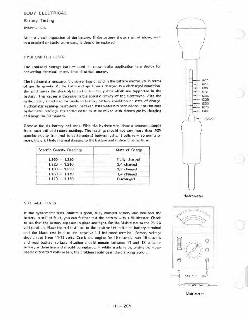
VOLTAGE TESTS
If the hydrometer tests indicate a good, fully charged battery and you feel the battery is still at fault, you can further test the battery with a Multitester. Check to see th at the battery caps are in place and tight. Set the Multitester to the 25 DC volt position. Place the red test lead to the positive (+) indicated battery terminal and the black test lead to the negative (-) indicated terminal. Battery voltage should read from 11·13 volts. Crank the engine for 15 seconds, wait 15 seconds and read battery voltage. Reading shou Id remain between 11 and 13 volts or battery is defective and should be replaced. If while cranking the engine the meter needle drops to 9 volts or less, the problem could be in the cranking motor.
III - 20b
)
1100 1125 1150
) 1175
120 0
1225 1250 1275
1300
FLO AT
Hydrometer
~-RED"+" ~
~L. _8~L~A~C~K _____ ~ (-./
Multitester

c
c
BODY ELECTRICAL
Charging System Operation
fLYWHEEL "'AGNET TO BRAK E LIGHT SWITCH
+ REO BLACK
BREAKER TO EXTERNAL LIGHTING
TERMINAL L TO STARTER MOTOR
TERMINAL N
+ TERMINAL 8
TERMINAL X
TERMINAL G
BATTERY
TERMINAL S
REAR V I EW O f IGNITION SWITCH
TO SECONDARY COILS
IGNITI ON SWITCH
RUN POSITION. LIGHTS OfF GROUND TO ENGINE
Before proceeding with any test procedures, you must have a basic understanding of how the Polaris charging system functions. Using the charging system diagram above, follow the current flow from the engine to the battery. Note the ignition switch position in the diagram. This "Run" position allows maximum alternator output to the battery. With the switch in the "Run/Lights" position (circuit completed between "X" and "L"1. the majority of the alternator
output is used for external lighting.
The lighting coil and flywheel magnets produce the current necessary to charge the battery. Because the lighting coil is influenced by the north/south poles of the spinning flywheel magnets, the voltage produced is first in one direction, then in the other, much like a piston moves back and forth in a cylinder. This type of current flow is called alternating current (referred to as "AC").
Since AC voltage cannot be utilized or stored in the battery, it is changed to direct current (referred to as "DC"). DC voltage travels through a wire in one direction only. The change from AC to DC takes place in the rectif ier. The rectifier has two diodes which are fed by the two yellow wires from the lighting coil. These diodes, or check valves, allow current to flow freely in one direction only. From the plus (+) side of the rectifier this DC voltage flows through the circuit breaker and into the storage battery.
The voltage regulator is a control device which siphons excess alternator output voltage to ground. The regulator limits voltage to 11-15 volts, which in turn protects voltage-sensitive components from damage.
The circuit breaker is an overload switch wh ich protects components from stored battery energy. Should a short occur in the system, the circuit breaker will overheat and break the current flow from the battery.
III - 20c

BODY ELECTRICAL
Charging System Testing
fLYWHEEL MAGNET
REAR VIEW OF' IGNITION SWI TCH
TO SECONDARY COilS
TO BRAKELIGHT SWnCH
+ REO BLACK
TO EXTERNAL LIGHTING
MOTOR }-----
IGNITION SWITCH
RUN POSITION. LIGHTS OFF'
BREAKER
+
BATTERY
GROUND TO ENGINE
All the components which are briefly described on the preceding page work in conjunction to maintain battery voltage and state of charge. If one or more of these components fails to function properly, the battery will suffer. The tests
for these components are as follows:
1. Alternator Output Tests: Refer to light circuit testing in this section .
. 2. Voltage Regulator Tests: Refer~to light circuit testing in this section.
3. Rectifier Tests: The rectifier has two diodes which are tested separately and must allow current flow in one direction only. Remove rectifier connections. Set the Multitester to the Ohms x 1 position. Place one test lead on the plus (+)
indicated rectifier terminal and the other test lead to the AC indicated terminal. Note the reading obtained, reverse the test leads and again note reading. If both readings are very low or very high, the rectifier is defective. A good diode will give one low reading and one high reading.
4. Circuit Breaker Test: The circuit breaker is tested with the Multitester in the Ohms x 1 position. Remove the circuit breaker connections and check between the two terminals. Readings should be zero ohms'resistance. If a high reading is obtained, the circuit breaker is defective.
5. Ignition Switch Tests: The ignition switch can also be tested using the Multitester in Ohms x 1 pOSitIOn. Check between designated terminals with wires removed. Example: Key in "Run/Lights" position, check resistance between terminals "X" and "L" (terminal identification letters are noted on rear view of ignition switch in above diagram). Multitester should read zero ohms resistance. When switch is turned to any other position, the meter should read infinite ohms resistance. If partial opens or shorts are noted, the switch should be replaced.
6. Wire Connections: Due to the low alternator output amperage, it is essential that all connections between the stator plate and the battery be clean, tight, resistance-free connections.
III - 20d
)
)

c
c
c
BODY ELECTRI CAL
Cranking System Operation
BATTERY
II1I1I 1 D-4+ t-------r------------
REAR VIEW OF' IGNITION SWITCH
TO SECONDARY COILS
CIRCUIT BREAKER
TERMINAL L
T ERMINAL hi!
TERMINAL B
TERMINAL
TERMINA L G
TERMINAL S
TO EXTERNAL LIGHTING
T O
________ IGNITION SWITCH ___ _____ -' START POSITION
The components which make up the cranking system are shown above.
STARTER, MOTOR AND SOLENOID
The battery is the sole source of electrical energy for the cranking system. Satisfactory starter motor life and performance are highly dependent upon battery condition and state of charge.
The ignition switch when turned to the start position completes the circu it between the battery and starter motor
solenoid.
The solenoid is a magnetic switch. As current flows through the ignition switch contacts and through the solenoid windings, two things happen in rapid sequence. The solenoid plunger shifts the pinion gear into mesh with the engine flywheel ring gear. Also, the battery is connected directly to the starter motor throu gh large contacts in solenoid.
The cranking motor converts the battery electrical energy into a mechanical energy which is necessary to crank the snowmobile engine. The cranking motor is a high horsepower unit which requires high battery current to operate and should never be used for more than a 30-second interval.
III - 20e

BODY ELECTRICAL
Cranking System Testing
BATTERY
TO EXTERNAL L IGHTI NG
.,------- - - - -- TERMINAL L
TERMINAL M
TERMINAL B
TERMINAL
'I. -...,---,1----- TERMINAL G
'--_ ______ TERMINAL 5
REAR VIEW Of IGNITION SWITCH STARTER. MOTOR AND SOLENOID
~ IGNITION SWITCH
TO SECONOARY COILS ~ START POSITION - ------'
The power supply for the cranking system is the battery. Therefore, the first step in testing the cranking system is to test the battery as outlined on the battery testing page in th is section. With the battery tested and fu lIy charged, proceed to test the cranking system circuitry and individual components.
SOLENOID DOES NOT ENGAGE
1. Large Battery Cables and Connections: Adjust the Multitester to the 25 DC volt scale. Place the red test lead to the battery side of circuit breaker and the black test lead to engine ground. The reading must be the same as a battery voltage reading (from + side to - side of battery). If the reading is not the same, excessive resistance is present between the engine ground to the - side of battery or between the battery side of the circuit breaker and the + side of battery. Check for corroded, loose connections and frayed or burned wires. Replace or repair as needed.
2. Circuit Breaker: Set Multitester to the 25 DC volt scale. Connect the red test lead to the auxiliary side of circuit breaker and the black test lead to engine or battery ground. Readings should be the same as battery voltage reading. If not, the circuit breaker is defective and must be replaced. The circuit breaker should also be checked for ohms resistance. Zero ohm s resistance readings are normal; high readings indicate poor contact connection in circuit
A breaker and it should be replaced. CAUTION: To prevent damaging the Multitester, all resistance checks must be taken with engine stopped and battery (source of power) disconnected.
3. Wire from Circuit Breaker to Ignition Switch: Set Mu ltitester to the 25 DC volt scale. Place red test lead on B terminal of ignition switch (terminal identification letters are noted on rear view of ignition switch in above diagram) and black test lead to engine ground. Reading should be the same as battery voltage. If not, check for corroded, loose connections and frayed or burned wires. Replace or repair as needed.
4. Ignition Switch:
Adjust Multitester to the 25 DC volt scale. Place red test lead to S terminal and black test lead to engine or battery ground. Rotate ignition switch to the start position. Reading should be the same as battery voltage reading. If not, replace the ignition switch.
III - 20f
)

c 5. Wire from Ignition Switch to Starter Motor Solenoid:
BODY ELECTRICAL
Cranking System Testing
Set Multitester to the 25 DC volt scale. Place red test lead to the small terminal of starter motor solenoid and black test lead to engine or battery ground. Rotate the ignition switch to start position and note reading. Reading must be the same as battery voltage. If not, repair or replace wires as needed. NOTE: Check for a good connection at main engine terminal block.
6. Starter Motor Mountings: The starter motor is also a part of the solenoid circuit. Be sure the starter motor solenoid and starter motor are securely fastened and grounded to the engine.
If the above systems checks are okay, the problem is in the starter motor solenoid, which is a sealed unit and must be replaced.
C SOLENOID ENGAGES/STARTER MOTOR TURNS/ENGINE DOES NOT TURN
c
c
Remove starter motor. Inspect flywheel ring gear condition. If teeth are missing or excessively worn, replace flywheel ring gear. Disassemble starter motor and inspect solenoid to pinion gear linkage; worn or bent linkage should be replaced. If inspections are okay, replace starter motor pinion gear assembly.
SOLENOID ENGAGES/STARTER MOTOR DOES NOT TURN
1. Solenoid: A. Set Multitester to the 25 DC volt scale. Place red test lead on the large terminal at starter motor solenoid
(battery side) and black test lead to engine or battery ground. Rotate ignition switch to start position and note reading.
B. Leave Multitester on the 25 DC volt scale. Place red test lead on the large solenoid terminal (starter motor side) and black test lead to engine or battery ground. Rotate ignition switch and note reading.
If readings from tests A and B are not equal, replace solenoid assemb!y. If readings are equal, the problem lies in the starter motor.
2. Starter Motor:
Disassemble starter motor and observe the following:
A. Brush Inspection:
B.
Brushes must slide freely in brush holder. Brushes worn to 1/4" or less must be replaced. Brush contact to armature commutator must be resistance free. If the commutator bars require sanding, use commutator sandpaper only.
Bushing Inspection:
Check rear cover and gear case cover bushings. Excessive bushing to armature shaft clearance will allow the armature to interfere with the field coils. Replace these parts as signs of excessive wear appear.
C. Field Coil Tests:
D.
Set Multitester to Ohms x 1 position. Check continuity between the large field coil solenoid wire and the insulated brush. Readings must be zero ohms resistance. Also, check field coil windings which may be shorted to the case. Place one test lead to large solenoid wire and the other test lead to field coi l case; readings must be infinite (open circuit!. Field coils which do not pass these two tests must be replaced.
Armature Short Circuit Tests:
With the armature insta ll ed in a growler, place a thin strip of steel on the armature. With the growler on, slowly rotate the armature one full turn. If the steel strip does not vibrate, the armature is not shorted. If the steel strip does vibrate, the armatu re has a short circuit and must be replaced.
III - 20g

BODY ELECTRICAL
Cranking Motor Exploded View
I
l
1 - Field Coil Housing 2 - Solenoid 3 - Sh itt Lever 4 - Lever Pin 5 - Split Pin 6 - Dust Cover 9 - Gear Case
10 - Gear Case Bushing 11 - Thrust Washer 12 - Thrust Washer
31
2
~
'1
I I I
4
20 ~ 9 ~ '~
13 ~ . 1;6/ 14
22 >~ I
19 I ~
I III 20 21
13 - Thrust Washer 14 - Thrust Washer 15 - Pinion Assembly 16 - Field Coils 17 - Brush (+) Insulated 18 - Pole Core Set Screw 19 - Brush Holder Assembly 20 - Brush Spring 21 - Brush (- ) Grounded 22 - Brake
III - 20 h
24
23 - Brake Spring
I
I
I
24 - Armature Assembly 25 - Rear Cover Assembly 26 - Rear Cover Bushing 27 - Starter Thru Bolts 28 - Rear Cover Attaching Screw 29 - Solenoid Attachi ng Bolt 31 - Engine Bracket 32 - Starter Bracket 33 - Starter to Engine Bracket Bolt 34 - Bracket to Starter Attaching Nut

c
C
C
c 1 2 3 4 5 6 7 8 9
10
C 11 12
BODY ELECTRICAL
Cranking Motor Exploded View - Drive Clutch Ring Gear Version
25
2
3
17
@tt:~'" 1."t'@0
@ C' n 22
@ rr I 12
@ I,C ' 23 . .n 24 \ ;--?~ 13 . ( / I
33 16 r~~ 34
~ I 35 31 "
21
@~ " " ~~
cY f~" " tY;::J 24 '; . 23
30 20 e ~ ~
18 19
I 15
~~ crY '" 29 28
32
- Field Coil Housing - Armature Assembly
- Washer Kit
Field Coil
Pole Core Set Screw Brush (+1 Brush Holder Brush (-I
Brush Spring
Rear Cover
Rear Cover Bushing
Pinion Assembly
13 14 15 16 17 18 19 20 21 22 23 24
~ 7
6 <::( cf 9
\ 27 28 29
27 28
Pinion Stopper Set Through Bolt
Dust Cover
Front Cover
Front Cover Bushing
Screw
Spring Washer
Engine Mounting Bracket
- Stud
- Nut
- Spring Washer
- Washer
111- 20i
6
8
I
J
25 - Ring Gear 26 - Solenoid
27 - Nut 28 - Spring Washer
29 - Washer
30 Bolt
31 Engine Mounting Bracket
32 Bolt
33 Nut
34 - Spring Washer
35 - Washer
3/81

w -00 ...
N o --,
u
STATOR PLATE
::: ~s
TII~7\'\ G
o
IGNITION
BlK
u
SCHEMATIC DIAGRAM 1981 CUTLASS SS ELECTRIC START EC 44-2PM 3300
(120 WATT ALTERNATOR)
RECTIfiER
Y / BlK
BATTERY
BLUE
GROUND TO ENGINE
PLUS
~
CIRCUIT BREAKER
BlK
+
u
TACHOMETER LIGHT
SPEEDOMETER LIGHT
STARTER SOLENOID
co
"" z
LIGHT SWITCH
... OJ (g 0 00 0 ... m -<
TERMINAL CD m (") r .-+
~ TERMINAL M ---' \
TERMINAL
~ m C:;' ("') Cf) -I
I TERMINAL
/ TERMINAL
TERMINAL
.-+ :xJ til ~
("') .-+
:E » r
~, ::l
CC REAR VIEW OF IGNITION SWITCH Cf)
(") :::r CD 3
TAilLIGHT til .-+ C:;'
DRN ORN I n
BRAKELIGHT SWITCH c:: tt til II>
BRAKELIGHT II>
Cf) Cf)
Y / BlK
TAilLIGHT
BRN
~ c
~ HEADLIGHTS z
u u

N o ~
(J1 -00 O'l
n
STATOR PLATE
'" r
" Ji
:;
'" :Il Z
~
n n
SCHEMATIC DIAGRAM SPORT, SPRINT, SS, TRAIL INDY ELECTRIC START EC442PM
(120 WATT ALTERNATOR)
Y
G
Me . 1
IGNITION SWITCH
BlK
RECTIFIER
BRN
Y! BLK or R
Y/ BlK
BATTERY
BLUE
GROUND TO ENGINE
:;
:Il
CIRCUIT BREAKER
<
Y
'" :Il
TACHOMETER LIGHT .2
SPEEDOMETER LIGHT
Y
LIGHT SWITCH
/ TERMINAL G
/ TERMINAL B
r----_TERMINAl M
rERMINAL S
REAR VIEW OF IGNITION SWITCH
ORN DRN
BRAKE LIGHT SWITCH
Y/ BlK
:Il Z
:Il
TAilLIGHT
BRAKELIGHT
TAILLIGHT
BRN
HEADLIGHTS
n
.... (0 00 W r-+
.... 0 (0(") 00 c: ~ ... r-+ ... o CD
:::J (") r-+ c: m ... -... CD CD (") :::J r-+ r-+ ... m (;. -CI) CD r-+ (") Ql ~ ... _. r-+ (") ~ CI) _. r-+ ... III _. ... :::J r-+c.c
~ en _. (")
~. ~ :::J CD Ie 3 en III (") !:!'. OJ ::r (") 0 3 1 0 III CI) -< !:!'. 't:l m (") 0
;:l. r-. m -i CI) (") ... CI) -i III JJ
CI)
::l ~ (") 0.. _. » < ~ r-

I:)

n
N ~
n
STATOR PLATE REGULATOR
BRN
SPARK PLUG
~
AC
AC
n --/
SCHEMATIC DIAGRAM 1979 ·340 . 440 COBRA
(75 WATT ALTERNATER) (ELECTRIC START)
CIRCUIT BREAKER
SPARK PLUG
~ '" ~ TACHOMETER (LIGHT)
SPEEDOMETER LIGHT
IGNITION COIL IGN ITION COIL
~ ,;:..'-> ~ --......... \~ ~ ~~" X
/ /
o~ ---- RUN
IGNITION
BLK
+
BATTERY
BLUE
n
EC - 34PM - G4 EC-44PM - 01
\ TERMINAL
~ TERMINAl M _ _ oJ \
TERMINA L
, I TERMINAl
":;;:1;7 TERMINAL
REAR VIEW OF IGNTION SWITCH
BRN
TERM INAL
BRAKELIGHT
TAilliGHT
n
~
<.0 -..J <.0
('") 0 C" ~ Ql
W ~ 0 Ql
::::l c.. ~ ~ 0
m CD (") .... ~
(")
(/) OJ ....
Ql 0 ~ .... 0
~ -< :! . m ::::l r I.C m (/) ('") (") -i ::::r
:0 CD
3 ('") Ql
l> =t. r (")

N N
FLYWHEE~MAGNETO-GENERATOR
---iJ 0
· 1r
"...,
(, ,( ) . \, /
.. ~ .-
r ~ri-------i'~------
J~ . ~.
~: , ~
CD SPARKPLUG
WIRING SCHEMATIC (PLAYMATE)
ITEM REO, PART NO. DESCRIPTION 1 1 2460071 ENG INE CONNECTOR 8SSEMBLY ___ 2 1 4110003 IGNIT ION-LITE SWITCH 3 1 2460070 MAIN HARNESS 4 1 2460069 HEADLIG HT HARNESS 5 1 403000R HEA _I(:;HT 6 1 4020023 CONNECTOR 7 2 2432008 TAIL LIGHT ASSEMBl Y 8 1 2460068 TAIL LIGHT WIRE 9 1 5223409 WIRING HARNESS CLIP
cp SEE MAIN HARNESS PLAYMATE HOOD
)J) OFF ' .- ":" -""'- _ I "'"'0'"'," ~ ~ . d' ~'" CD ;,-+- / S ' - ~ /
G c>--- . ' . r--- I . L .. . ",. m i. I t ~ 1
HEADLIGHT
.~CD ,--'
I!
CD
__ SL _ _ ._J I II!
IGNITION-LIGHT _ 1 =':c . STARTING SWITCH
.---.
TAIL LIGHT DISCONNECT
~
TAIL LIGHT
u u
... o:J (0 -..J :> ... 0
~ -<
:;' m 5' r
(Q m en
("')
(") -i ~ :::0 (!)
3 ("')
Q) » .-+
n' r
"'0 Q)
-< 3 Q) .-+ (!)

N W
( I
n
~ 8'
~ ~,
/ '-' ---,
I .~-[1 \ ~ C ~ ~ '~j ,;. .
'~~ FLYWHEEL MAGNETO
GENERATOR
n n
WIRING SCHEMATIC (MUSTANG - CHARGER - ELECTRIC START)
STARTING MOTOR
STARTER (~ SOLENOID CIRCU IT 1-- -,
~ ~_ 1-' ~ ~--------h~~Q;!' ;:====-.,. I, li--.. ----rL
V ~ - --.J -----, I ~, I f "-" I . r ~ I I
n
"en"" - - ~ ""'" , '-; ~
f.' '" I - J , __ - .f..
''''4';' ~'~ _I, I LtJ r\0'"'"'''O''' ,
J LITE SWITCH i I
-:-
rri-y('l I r~ I
·i:" I ' ,=, _I
L
EXTERNAL IGNIT ION COIL
L_ EXTERNAL
IGNITION COI L
- - - --, " WARN ING LITE SWIJ;~~N I NG LITES I" ,"/ " _ _ -, I ' ;/ 0 J 1
I , --.l \ ~' "'T ~,-6-;o-6 ", '- 1 '0.) \~ . I <AI""" 1
I ffi )\, I -\1) {(V I
1 I
___ _ J l 1. L IGNITION STARTING SWITCH
TO CIGARETTE LIGHTER IF INCLUDED
t DUAL BEAM HEADLITE
TO SPEEDOI\ ETER & TACHOMETER LITE- I F iNCLUDED.
... (.0 "'-I ... ~ ... ::::l to
C/J (")
~ CP 3 Q) .... C:;'
I ~ c: VI .... Q)
::::l cp ("') ~ Q) ... ~ ...
m CP (") .... ... C:;'
OJ o o -< m r m ("') -i :::0
~ ("') Q) » ~ r

N .j::o.
~T+----C
/: I' ! • ,h ~ ~ , ~. I .. j:
1 i ~1
r U
[l FLYWHEEL MAGNETO
GENERATOR
WIRING SCHEMATIC (MUSTANG - CHARGER - TX - MANUAL START)
SPARK~
-=-
I ~
IW-(,]- !ni! '- ~ ~<<l I I - I I I:-=:k=-
II I J'I I L __ --.I L __ ~
EXTERNAL EXTERNAL IGNITION COIL IGNITION COIL
_ . . _ .. ' (Twin Cylinders Only)
-- \ u
~QI~
1 - ON MUSTANG ONLY 2 - MUSTANG, CHARGER, & TX
1------
-;;q-!: ITE SWITCH I I 1- ,- -, \
(NOTE 11
WARNING LITE SWITCH
I~' ~ 1/ - \ f'" .. \ W'R
4: ING L~
LOFF 6'-Lo6~ 1
DUAL BEAM HEADLITE
\ _ / ", / '1,
'''''~ ~ . . ~~ (j) [ '.,~ I
_.L I L
..... CO u;) -....I 0 ..... 0
~ -<
=- ' m :;' r to m
("') C/) n -I ::T :::0 (l)
3 ("')
til » :!" r n
I :s c en .-+ til :::t tp
("') ::T til .. to (l)
," -I >< I :s til
I :::t C
I !:!. C/) ...
[ til .. ...
I I I I
-'

n
N <.n FLYWHEEL MAGNETO
GENERATOR
EXTERNAL IGNITION COIL
()
-::-
IGNITION STARTING SWITCH
()
WIRING SCHEMATIC (VOYAGER)
SPARKPLUG
~
EXTERNAL IGNITION COIL
7.5 AMP 20 AMP
i-=t:...l BAT. I I
LIJ
LITE SWITCH -,
DUAL BEAM HEADLITE
STARTING MOTOR
STARTER ~
~~1- ( J L~ ~ ~
1---------1 I
" WARNING LITE SWITCH WARNING LITES
~-ITES -; ----{~ 4 I -=- 7" I L __
I I I
J
)
TO SPEEDOMETER It TACHOMETER LITE- IF INCLUDED ..
.... <.0 -....J .... ~ :::!. :::l to
Cf) OJ (") 0 =r (I) 0 3 -< III 0". m (") r
m n
< -i 0 ::0 -< n III to » (I) .... r

N (j)
HEADLIGHI GE 4465
HEADLICHT
C E 4465
u
Br
Br
B BI
HEAOliCHT HARNfSS CONNECT OR
. Black Blue
Br .. Brown G· Green
Orange Red
Y Yellow W Wh ile
WIRING DIAGRAM
R/W· Y/ B · Y/ C YI R
IlICl CAll[ TO 'IOUI III ml~[ FI~ WOUS IN' i
m CI CIIlE 10 slUm
R
~ R
CURCUIT BREAKER
Br
Red lII'ilh while tracer Ye llow with black tracer Yellow with green tra cer Yellow with red tracer
u
-----10 SIARHR SOl E.OIO-----,
--------10 STII HR SOlENOID--------.,
I B
IC IR
Rtov.E!l y-BI
G\
AUX ILIARY SHUT orr ~CH \t R/W6
IWO UB CO NNECIOR
ENCINE CO NNECTOR STANDARD ICN ITIO'
ENGIN[ CONNECTOR
8r l Y
I I
Br
I r
BRAKELIGHT
""'"ru I
L)
f"'tllH CONN£CTOR· CD IC 'I IIION
BRU[LICHT
G E 89
TAilLIG HT CE 189\
u
.... CO (0 -...I 0 N 0
::2: -< 5: m :::J r to m
("') 0 -t Qj ' ::0 to .., ("') til
3 :t> r
I
~ c: en r-+ til :::J !P ("') ':r til .., to (I) ..,

N --.J
n n y
MMt.J£TO GEIVENATOf(.
TACHO'I"rE ..
..g:R~
REC.T1FIEi II
"
BLAC!oC CA BLE
()
STARTEII SOLENoro
'"
~ARr"'f/
MOTOR
()
SPAf(1( PL/J..Q.-* SPARK PLU/V. 1 -=
""I
IC,NITION COIlJI'
NCTE1: MIl.STANG-, C.HA~U, SS 'NITH STAN DARP POINT II:.NlTION AND CAPAc.ITIVE: DI: 5CHARb--E IG-NTTION AS PER NOTE .2. TX 335 ,<is PER NOTE 2.
I I I I
~
BLK
I I
.-L
( ACC£SSORY ) cH~RT LIilliT Cl:&~11 LIGHTEi
~ //-, L...- ___ ~
\ , /
X No n:2:DTAGRIlM DO£S NOT ~ 11 0W' CAP ACITOR DIS(HARG-E
IGi'<TTION PARTS AND WTRING-. 5TANDARD Ir;NIT'I.ON PARIS SIlOW'N W I TH (*) .
~
L!/'HT ISWTICH
+
~. -1-~LA~K 1~A8LE
0 1<"
BATTERY
MUSTANG, CHARGER WIRING SCHEMATIC
g RAKE LTG HT S WITC H
-I t J ~'. ".~u'"'
cD I."'ti f ~
Y/ BLK
TAILL-
5ct
..... to --.J N
~ ::::! • :::l
(Q
en (') :::T ~
3 III ~. (') OJ
I 0 CJ
:s: -< c:
m VI .-+ r-III :::l m
rp. C") -f
("') :JJ :::T III C") .... » (Q ~ r-....

~
MAGNETO 6ENEaATOA
RE(7I.lLATO~ (~CCESSOl y)
Ill'"
~ ---l
Gll
CD~ (l)~ ~ y
8RN
SPARK PLUG SPAR/<; p~ ",w
~ <1-=
ow un rG/{ITrOfl{ COIL IG-NrTIO/ll cor L
BRN! I NOTE 2
AUXILLARY ~ H U.T-OFF --1...::---, 11; SWITC\i -
IGrNrrWN_ LI<;,H-r 5 \,.u:!. I e H
M A /(f BEFoflE 7JII.EA k.
HEAD LIG.HT CONNEC7'TONS
NOTE 1- /75 ee. ENG-INE HAS A SIN&LE REO AL7€IINAfOR LEAl)
ANO -4 1J~OItVN £"XTEIVV'AL & KOY.NO LEAD.
yI SL/<
NoTE ~ t7!> e.C . EN(;INE ANO 250 cc. ENG-XNE HAVE A SIN'-tLE rNT~RNAL Ir;.HIrrolV COIL ANP A WIRE: '-ROlA.JtlUe:O
TH~OUGH IGNITION SWITCH O Q SHlA.T-OFF SWITCH 6H.U.T O FF t:Nt;l. NE .
!VOTE 3 :; . C.O~T HAS SIN& LE HEAOLr:"' IIT.
I
.,j"
TO OTHE. (;/lOu./lU PoXNfS THIlOU.<>H HARN£S$ES
.~~~~~ REAR VrEk/ OF a50 ce , AND 2q~ eC. cN<iT.NF:
IGN~"'IOIV - L.l&~T S",XTc H
'~/0 \ /I~
---eEAII. VIEW OF 17SCC, ENfiINE
I&NITI.Ofl{ - LIG-HT SWIre H
r---~-------------------------------a.~-- - - ~ SP£ EDOMrTER.
G-
.,. R NOTE 3
8LK LIGr Ji T (1 ) ,~<~.o .. ,
-J!CN
TArLLXwHT
COLT WIRING SCHEMATIC
L u u
.... OJ ttl --.J 0 N 0
~ -<
:::;' m 5' I IC m en
(")
(") -I :T :::0 CD 3 (")
Q) » .... n' I
(") 0 ....

N c.c
""'"' '" ~ ~ <= s:1~
STATOR PLATE
'"' ;;
W
BlK / W
BRN
ORN BRN
r -- --,
I I I I
: 0 0 I I I I c, 0, I I ICNITION I I UNIT I I 0 0 I
I L ______ ---'
REGUL ATOR
SCHEMATIC DIAGRAM 1973 CONSUMER TX
(140 WATT ALTERNATOR I 3 CYL.)
,----------TERMINAl
~TERMINAl M
TERMINAL B
TERMINAL X
-.yI / - TERMINAL
REAR VIEW OF IGNITION SWITCH
/
Of- - - - RUN
TERM INAL
• " ) 8° • 7 S0 ./'4:
~/' IGNITION SWITCH
... " '"' ~ ""
SPARK PLUGS
~ r~ ~
'" '" z
n
BRN
TACHOMETER (LIGHT AND FUSE)
8RAKELIGHT SWITCH
TAILLIGHT
8RAKELIGHT
~ BRN
-TAILLI GHT
SPEEDOM E1E R LI G H T '----;('--__ LICHT SWITCH
BRN ICNITION COILS
f)
.... c.c -..J W
en (")
~ (I)
3 Q)
~, (")
0 Qi '
(,Q OJ ....
Q) 0 3 0 -<
(") m 0 r :::l m <II C"l c:
~ 3 JJ (I) .... C"l ~ » >< r

w o
COLOR CODE BL---- BLIC' BLU---BLUE BR---- BROWN G---- GR[[N OR--- ORAIIC[ ' ----REO W---WHIT(
' --- YELLOW
o
ENGINE
CO ILS
WIRINC DIAGRAM CONSUMER TX
~~ ___ l1iTI TO ENGINE
~' TA~HoMmR J en ONL
,~ ------- - - --~, L
a r - - - - - - - - - - - .... AUXI LIARY SHUT Off
~ 1I 1I 11 n -] L~it lDf Y/~~ " ~~~illn:~~u--~ . ~~RI ,i:
... ... . • I~ ~ ...... ' ' ' 1~1--un ____ u-Y~~DrYTBr--- --- - :1 ]1 ___ ~RJl....F OR ---- tllil'
' BIl_ - L __ _
-.. ~. rr-----r ~~ HEADlICHT
1
.1'
~Ji HEAOLIGHT c [ H~
i I
'1'11' 'I : II : I I II I I
:!,: J' : "" I I I : : I I 1 I I I I I I I II I I I I I I
: ~R:UClBRdllll: I~G Y/G~' L ____ _ _ R .. y_R __ _
u
BRAKHICHT SWITCH
~::; j----------------~ ~lnFr1~ Ii
I r----------- ~ tj~
___ j II: ORuR ~j
o UCHI SWITC H
u
SWITCH
TAIlliGHT G1 189\
BRAKEUC HT
Gl 89
u
.... c.o -...J W
~ .... ::l
(Q
o OJ
(Q .... OJ
3
("") o ::l VI c: 3 en .... -i X
co o o -< m r m ("") -i JJ ("")
» r

n
w ->
n
STATOR PLATE
1:1 I. I;; I! •
II I 1
1(0 1
1
R; W
BlK
----,
C. D. IGNITION
UNIT
1
1
1
1 lQl ~ 1 '---___ --.l
ORN
W
BRN
REGULATOR
BRN
()
SCHEMATIC DIAGRAM 1973 CONSUMER TX
(140 WATT ALTERNATOR, 2 CYL.)
REAR VIEW OF IGNITION SWITCH
TERMINAL
TERMINAl
TERMINAL
TERMINAl
TERMINAL
TERMINAL
t::::: ~s ~--------.. ~ ~~
~" X
O~ --- RUN
.".-1J0 -< "-;;
()
M
B Y/ BLK
BRN
TACHOMETER (LIGHT)
BRAKELIGHT SWITCH
TAILLIGHT
~ I I ~ ORN
Y I BLK
J'~ S rW • ~ BRN"-IGNITION SWITCH :;> ~( r--------
iil-Z, SPARK PLUGS
~ r~
... ~ z
SPEEDOMETER LIGHT
TAILLIGHT
LIGHT SWITCH REO
GREEN
IGNITION COIL IGNITION COIL BRN
----
()
-> (0 -..J w C/) n :::r ctl
3 Q)
d". n
0 Qi' te CO .... Q) 0 3 0
-< ("") m 0 r ::::l m <II ("") c:: -I 3 ctl :::JJ ....
("")
-I » X r

W N
WIRING DIAGRAM MUSTANG, CHARGER, CUSTOM BUCk CASlE TO GROU ND ON EHG INE FAN HOUS ING
BLACK CABLE fO SURT£~ 10 SIARTER SOl£HOIO
10 lA' HOUSING
IfT~O ~S~IA~RT~E~R ~S~OI~EH~0111u
III w
CIRCUIT BREAKER r=i --~
- - - - - - - - - -8l'~ SHU T-Off SWITCH 'I -----J AUIiIiARI illl :--u
-
BA T TfRY
113456
400
I I I I I I I -[~un~'l i i
, BR~ I I SPHDOM ETfR ~Y/8lm I : ,OPIIO'AI i ;:
BRAKHIGHT SWITCH : ~~~\~~ ,IN I I :
I I
, I I I , , , , ,
~I IIII I ~;/~ __ I,nnn I 11 11 ~tl'[-:-;iW' 1E::~~~~o'Jl~) ill I
, j§,,, ___ .. ," " I RlU _ , , ' I L ________ I, V/G
: , : : , ' : , , : ",.,," : , , : I
".,"'" '''~." I" : : I I 'II 1
" ." ••. m ~: ~ ______ J I t==1 I 1
' ~ -------, ,- 'l'~ : : , ! nmm "'±ffl"; ' - .. nmn' '00 . 'I 1 ' '"illi" ' .___ ''" , 1) ~ § -- --___ m_' ,'''''''' ':''"_.'''''', ~ ~l~"'--: ~ =~=_--_-_-_-_ = = = ~~ = ~ ~ ___ ' , '""''''' ~ ---- " G E 4465 195 CHARGER _ [ _________ _ __ _
G E 4414400,530 _ _ _______ _
IIG", SWlleH 0
u
, :1 :
I,
!I
COLOR CODE Bl-- - BLACK Blli - -- BLUE BR--- BROWN G- - -- GREEN
OR ··· -- OR A'G[ R --- R[O W---WHlTt V-- -- YEl l OW
TAi lliGHT
BR AK EUCHI G[ 89
~
..... c.D "-I W
~
:::l c.c
0 Oi '
c.c ... tll
3 I :s: c: til ... tll :::l '? (") ::T tll ...
c.c CD ~
(") c: til ... 0 3
OJ 0 0 -< m r m (") -i :lJ -(")
» r

w w
n
STATOR PLATE
AUXILIARY SHUHFf SWITCH
,-I I
'" ,.
M
G
----,
I
011 I I
I~I I I L---- ____ ---.J
C. O. IGNITION
UNIT
IGNITION
IG NITION COIL
SCHEMATIC DIAGRAM 1973 - 530 CHARGER I 530 MUSTANG
(140 WATT ALTERNATER ~
RECTifiER
CIRCU IT BREAKER
Y/BLK
'" '" z TACHO METER (LIG HT!
Y / BLK SPEEOOMETE R LIGHT
BLK STARTER
+
BATTERY
BLUE
SPARK PLUGS
~ LIGHT SWITC H
n
,---------- TERMINAL
~ TER MINAL M . __ ...J \
TERMI NAl
~ I TERMINAl
__ '::;;;2 TERMINAl
TERM INAL
REAR VIEW Of IGNITION SWITCH
ORN
YI BLK
... ~
'" c
BRAKE LIGHT
TAILLIG HT
BRN
HEADLIG HTS
:l
.... <C -....I W
C/l (")
:::r (l)
3 III .... Ci'
0 OJ'
(,Q .., III
3 OJ 0 0
(") :::r -< III m .., ~ r-.'" m
(")
~ -l c:: ::0 (/I .... (") III :::::I l>
(,Q r-

w ~
u
TO STIRTER SOLENOID II BLU
TO fAN HOUSING
?TO~ST;;;AR=I[=R=S=OL=EN=OlgLU
w
'00
BRAKHICHT SWITCH
WIRING DIAGRAM MUSTANG, CHARGER, CUSTOM BLACK CAlLE TO CROUHD ON ENGINE FAll' HOUSING
BLACK U8l£ TO STUHR
UTl£RY
CIRCUIT8REIKER FI
BL - - - ---8l'l~Off SWITCH '[1 - ~ IUIll1lRY : 11:--, I I I I I I I
~~lllUg]~'I~~--~~ I: -r--8!~ : I: ' I I I I I ' I I : :, ,
: BRl : 1'11 : ': =YlBLl l '1" 1: : : : : "II ; I I I I' : I l' ' , ' ,
" , ,
I!: Iii
:~~ ~ Y/~JJI ~I I ~! I
.: :111
11
_~ Jj~ '1" "'.''' : : I b' :1'
HEADliGHT C( 4465 195 CHARCER C ( HS4 ~OO. 530
~ H£AOUCHT
C [ H6S 195 CHARCER C ( 'us~ 400. 530
h -----YiR~p-- djj:: ~R Y Y/R I C_' __ ' ____ m'~iill' r Vr n
' : ~ : II - ._BJL____ : I ----~ ,
HEADLIGHT ~ooo ' ~ .,,"" 00,""'" "" : _ __ r: '-_ 1! ,~ c," - - - " I
"'" .. ,," ~ <[ _J1~l __ Ii
COLOR CODE BL---BLACK
BLU--- BLUE BR--- BROWN G- - -- GREEN
OR--- ORANGE R---REO W---WHITE Y---- YELLOW
TAIlliGHT
CE 189S
BIiAKflIC,Hi C[ 89
... txJ (C -..J 0 W 0
~ -<
:;' m :;' r
(Q m (")
0 -i Qi' JJ
(Q
@ ("')
3 » r
I s: c '" .-+ Q) :::l !P ("') ::r Q) ..,
(Q CD .'" ("') c '" g 3

w U'1
n
STATOR PLATE
()
IGNITION COIL
IGNITION
REGULATOR
BRN
AC
AC
SCHEMATIC DIAGRAM 1973 - 295 CHARGER, 398 CUSTOM
(75 WATT ALTERNATER)
CIRCUIT BREAKER
SPARK PLUG
~
SPEEOOMETER LIGHT
IGNITION COIL
BLK
+
BATTERY
BLUE
n
r----------- TERMINAL
~, TERMINAL M
TERMiNAl
, I TERM INAl =1' ~ ! TERMINAL
TERMINAL
REAR VIEW OF IGNTION SWITCH
BRAKELIGHT
Y/BLK BRN
TAILLIGHT
HIGH~/~
""-V>~ I~ ~ LIGHT SWITCH
HEADLIGHTS
n
.. c.o "-'J W (I) n ::r CD
3 Ql !:t, n
0 Di' ce .., Ql
3 OJ 0 0
(") -< ::r Ql m .., r ce CD m ,'" C1 (")
-I c: :::0 en C1 .... 0 ~ 3 r

w O'l
WIRING DIAGRAM MUSTANG, CHARGER , CUSTOM BLACK CABl£ TO GROUND ON (HG fN£ FAN HOUSINC
TO STARm SOlENOiO BlU
Ii 10 fAN ~O U SING BLACK CASLE
TO STARTER SOl [NOlO BlU
m CHARCTR CUSTOM 400
W
400
~LJ "'" HEADLIGH T . ,
530
~ OR Y .;=="I!~!U!' !!'I '! ! II
BRAKf li GHT SW IT CH
,1 1 1 1 11~;,~n:mm Jl I~R/W i l __ _ ___ _ _ _____ _
c .
Bl
BAr TERY
; - - - - - - - --Blil~ I , - - - - - _...J AUlIliARY SHU T·Off SW ITCH I I : I
I I I I I I I I I I I
: · i 1lQ~"~~- m!11 I 1 1 1 1 I I I 1 I 1 I 1 1 I 1 I I
1 I 1 I
: 1 1 I I I ,
Ij Y/ BlW
GE <465 1195 CHARCTR ) dlllll' I
C[4454 14 00. 53 0 } rJ;/~ : 1
~ ~: : I
I BRl P :: I:ulmr ~ I
ts- -Y/R~.' 1- ' Y/C---J i ~~L Y/G . 4 Y/G I . E BR -7 _ 7 ~ BR I
H[A OliG HT - - - H[AOliCH T HARNTSS C:~H~::R- - - ---" ~~91~21~' G[4465 ,195 CHARCTR ' ~ 'i~: l _____ _ G ( 4454 400 , 530 :~ ;:"'~Y~/B~l~~~~~~~~~~~~~~~~~;:;;~
~ [-------- - ~ i liGHT SWIT CH 0 ---- -'--'
----
COLOR CODE Bl=== BlACK BlU==- BlU[ BR = = = BROWN G- - -= GR[ [ N
OR== = ORANG[ R = = = R[O W===wHlH Y---- Y[llOW
IAllll CHT G[ 1895
BR AKEtIf,HT C £ 89
~
c.c -...J W
:E :::;' 5'
(Q
0 iii'
(Q ... Ql
3 I S t:
'" ro+ Ql ::s ~
("') ::s-Ql ...
(Q (!) . ... ("') t:
'" S' 3
OJ 0 0 -< m r m ("') -I :0 ("')
» r

W -...J
()
STATOR PLATE
()
REGULATOR
BRN
IGN ITION COIL
IGNITION
AC
AC
()
SCHEMATIC DIAGRAM 1973· 398 CHARGER, 398 MUSTANG
(140 WATT ALTERNATER)
CIRCUIT BREAKER
SPARK PLUG
~ ~ :; !
SPEEDOMETER LIGHT
YI BLK
+
BATTERY
BLUE
() ( ')
.;:---------- TERMINAL
"'.-_ TERMINAl M
TERMINAL
I f - TERMINAL =, I TERMINAL
TERMINAl
REAR VIEW OF IGHITION SWITCH
BR AKELIGHT
~
Y/ BLK <.0 -...J eN
TAILLIGHT en C')
:::r BRN CD 3 Q)
~, C')
0 iii' (Q ~ Q)
3 OJ HEADLIGHTS 0
0 (") -< :::r Q) m ~
<g r m
-~ (")
$ -I c: ::0 II> (") .-+ Q) » ::l
(Q r

w ():)
115 250
WIRING DIAGRAM COLT
194 PM 19< PI 340 PI
o=~QjQ~ - , 1 (leU{ eOIlJi£C TlGII --- ~
_mUll ..
~ HEAOLIC HT
C E 4465 ICOIT II 195. JJ5 1
~ HEAO LIGHT
C E 4465 (COLT II 195, JJ5 1
~ HHOLICHT
C I 44'0 I COLI 175 .
C I 44\' <COLI 250. 1951
I I I I I I t ... _--,
i~S .... -r------'
I rFri~c~-~-~,~~~ I
I I I I I I I I I I I I I I I I
~BRAKElICHTSWUCH : i
: I I I I
8f-~---_-_-_--~~ ~IJ
------------yR5 1. TlG • ' BR _ T· ---------------
i------- Y/R~ I V/G . • I BR :1-I r -I I , I
r _ _________ J : HEAOliCHT HARNESS
___ J CONNEC TOR
I ______ _ I r--I I AUXILIARY SHUT·orr SWITCH rC--L----------~~~~-~ I I
! : '" --------; .. iJA ___ J L--:n:::=iu," . - ~--------------------
I
i i I
(tOlT ss om )

w CD
o
NOTES '
n
SCHEMATIC DIAGRAM 1973 COLT
(75 WATT ALTERNATOR) STATOR PLATE
RE GULATO R
ORN
SPEEDOMETER LIGHT (C OLT SS ONLY)
LI GHT SWITCH
IGNIT IO N COIL RlW
IGN ITI ON COIL
Of- - - -- RUN YlBLK
." ) °B • 7 ° .r~ S
IG NITION SWITCH ~ ..... ENGINE GROUND STRAP TO CHASSIS ON 175 CC COLT
175 CC AND 250 CC ENGINES HAVE A SINGLE INTERNAL IGNITION COIL AND A WIRE GROUNDED THROUGH IGNITION SWITCH OR SHUT· OFF SWITCH TO SH UT OFF ENGINE
COLT - SINGLE HEADLIGHT COLT SS - TWIN HEADLIGHTS
n
\ TERMINAL ~, _ TERMINAL M
TERMINAL B , I TERMINAL X
--;/ ;7 ==TERMINAL G
REAR YI EW OF IGNITION SWITCH
I I
TERMINAL
BRAKE LI GHT
Y/ BLK
BRN • VCJ TAILLI GHT
GREEN
RED
)
... CD -...J W
en (") ::r CD 3 ttl III 0 !:!" 0 (")
-< 0 iii ' m to r-... m III
3 C") -i ::l:l
C") C")
0 ):> ;::; r-

BODY E LECTRICAL
1974 W" " iring D" lagram - Consumer TX
(
(~
III - 40

c
c
C
C
II I I I 0 I I
10
STATOR PLAT[
R, •
'"
I "--__ ..Y
L- _____ ---1
STATOR PLATE
!Il~ ill - "
ORM
BODY ELECTRICAL
1974 Wiring Schematic - Consumer TX
WIRING SCHEMATIC
1974 CONSUMER TX (140 WATT ALTERNATOR, 2 CYU
REGULATOR L _ _ ~ V-- .--- T£R MINAl
TERMINAL
TERMINAL
TERMINAL
TERMINAl
TERMINAL
'RM
, , -"
\:r:.~ - -REAR VIEW OF IGNITION
SWITCH
IGNITION COIL
1974 CONSUMER TX
BRAKE LIGHT SWITCH
TAILLIGHT
SPEEOOMETER LIGHT
BR'
(140 WATT ALTERNATOR , 3 CYL.)
SWITCH
L
REAR VIEW OF IGNITION SWITCH
:::::::~,;j: :1'" TERMINAL x f[RMINAL G BR"",-*+---<",. HRM1NU s y
TACHOMETER (liGHT ANO FUSE)
e TAILLIGHT
AUXILIARY SHUT" OFF I
~-------r------U 'UI • 'RN ~ :±t=8'==~
IR' TAILLIGHT
1
~) I SPEEDOMETER LIGHT
• .. , r-- --I I I I I I I I 0 a I I I ~ O. I
''_0 ___ _
I ICNITION I I
UNIT I I 0 0 I L ______ J
ICNITION COILS
111-41

~ N
-..
u
[C 17 PM
WIRING DIAGRAM COLT
EC 15 PS
ENCINE CONNECTOR
EC15PC EC19pr ECJ4PC
11" Ww _ -------fj/W- .
4 615 ~
r-- II ...J [) ,u! r--- AUXIliARY SHUT ·OTfSWITCH
o ---r-c--c:=J I : : Y~ BR II
o 8R I :
o == II ! !_="u ~ t::~::; 1111 =' _____ .J! - OR ~'/8W ~ 'I J/8L r -, JF _ f----REGULAIOR I _ Ih- : I 5PEEOOM[l[R'
i r--' : II II! !! : : II II: illJ : I
~I "~ii, HEAOLICHT CEms
(COLT 150 . 195 ICOLT 55 150, 195, lIS)
~ HEADlICHT· C E 4415
(COL T lSI, 21S1 (COL T ssm, 215, 3lS)
: i 1 1 1 1 1 1
?l :: 8RA,rllCHT SWITCH I 1
I I 1 1 : I
______ J i
~~:L____ J
-------------~f~1 ! BR~ L _______________ "
,~ "Mlr:=
~' !Ifl~~~-----I~~I
I : I n ____ ~FL!5
Qr n' ~
, ----~~~~~:~~] CONNECTOR
HEADLIGHT · G E HI2 (COLT T751
u u
I I
: I I I I I I I I I I
I I I I 1 I I I I 1 1 I I I 1 1 1
L ill Y
Ii
lICHT SWITCN
u
BRAKEUCHT
CE 90
TAILLIGHT
cr 194
' Op tional on All ["'pI Colt SS
COLOR CODE
8LK 8LACK 8R BROWN G GREENE OR ORANGE R REO
WNITE YElLOW
... OJ c.o '-..I 0 ~ 0
:E -< :::; ' m :i' ,...
(Q m ("')
0 -! iii' :0
(Q ~ ("') Ql
3 » ,... I
~ ;:;
v

o
I fj
n
STATOR PLATE
ORN
PLUGS
RlW
o SCHEMATIC DIAGRAM
1974 COLTS & 250 CUSTOM (75 WATT ALTERNATOR)
~ SPEEDOMETER LIGHT
(OPT IONAl AlL OUT COLT SS )
IGNITION COIL RlW
IGNITION COIL
x
Of-- --- RUN ~
." ) °8 • 7 °
.r~ S IGNITION SWITCH ~/
NOTES :
1. 175 CC AND 244 CC ENGINES HAYE A SINGLE INTERNAL IGNITION COIL AND A WIRE GROUNDED THROUGH IG_ITlON SWITCH DR SHUT-Off SWITCH TO SHUT Off ENGINE
2. 175 COLT HAS SINGLE HEADlI'NT
o
~------- TERMINAL => _ TERMINAL M TERMINAL 8
X
• _ .{ / TERMINAL G
REAR VIEW OF IGNITION SWITCH
TERMINAL
8RAKE LIGHT
Y/ OLK
ORN
TAILLIGHT
GREEN
()
... to -...I ~
V> (") ::r CD
3 Q) r+ (")
9. Q)
c.c OJ .. 0 Q)
3 0 -<
(") m r-
0 m .r+ (")
(") -;
c: ::0
'" (") r+ 0 ~ 3 r-

Y ELECTRICAL Custom
BOD _ Electra, Diagram 1974 Wiring
)
III - 44

()
STATOR PLATE
Ci
REGULATOR
IGNITION COIL
.r~ S IGIITION SWITCH ~.I'
()
SCHEMATIC DIAGRAM 1974 400 CUSTOM
(140 WATT ALTERNATER)
SPARK PLUG
~
Y / BlI(
BATTERY
BLUE
'" '"
CIRCUIT BREAKER
+
SPEEDOMETER LIGHT (O PTIONAL)
()
__ - - - ----- - TERMINAL
TERMINAl II
TE RMINAL
~TERMINAL
~TERMINAL
TERMINAl
REAR VIEW OF IGNITION SWITCH
TAILLIGHT
OlIN
BRAKElIGHT
BRAKElIGHT
y/BlK BRH
BRN TAILLIGHT
HEADLI GHTS
(~)
--e,p -..J ~
en n ::::r (I)
3 III ~. to n
0 0 0
III -< (C .., III m 3 r
m (")
(") -I
c: ::0 en (") ~
0 » 3 r

ELECTRICAL m BODY _ Electra, Custo D" ram 1974 Wiring lag
)
)
)
)
)
III - 46

.j::o. '-I
n
STATOR PLATE
n
AUXILIARY SHUT· OFF
SWITCH
~ -----.... if' ~b
M
~
'"
---,
I I I I I I I
L--- ____ --.J
~
IGNITION SWITCH
OR
W
IGNITION COil
n SCHEMATIC DIAGRAM
1974 - 340, 440 ELECTRA & 530 CUSTOM (140 WATT ALTERNATER)
RECTIFIER
Y / BlK
BATTERY
BLUE
SPARK PLU G
1 PLUS
1
CIRCUIT BREAKER
BlK
+
TACHOMETER
SPEEOOM£TER LIGHT
STARTER SOLENO ID
LIGHT SWITCH
n
,------------ TERM INAL
~ TERMINAL M __ oJ \
HRMINAl
C ! TERMINAl
~2 TERMINAL
TERMIHAl
REAR VIEW OF IG NITION SWITCH
ORN
YI BlK
., ~
~
BRIKELIGHT
TAilLIGHT
BIIN
HEADLIGHTS
()
.... to '-I .j::o.
en (') :T (l)
3 Q)
~. (')
9-Q) to ... Q)
OJ 3 0 0
m -< CD m (') r '"" m ... .?' n
-l n ::0 c: VI n '"" l> 0 3 r

1975
RECULA TOR
I
til
~ HEADlICHI ' Cf 4495
WIRING DIAGRAM COLT
111111111111 ~, BRYRWY
B
,____ _ ___ 0, I R/W~ ~ .R_ ..
: AUXIliARY SHUT-Off SWITCH I I I I
hlllllllllld - 1:~5I:~ = 1O~::t..YY : fr~_---~ U~~-I
c!mElICHl SWITCH
I I I I I I I ,
~iMI- 'II ' ~_o~ ______ ~
SP HOOM£H RO
--
IACHO"l[l[R"
141l 1iCHI
CI 194
'Optional on All Except Coli SS
COLOR CODE
81 ~ 8L ~o.
BI! 8RO""~'
C CIH PH OR OR~ ~ Cf
RI O III HIIf
YH lO I'l
... co (C 0 ~ 0 ~ -< ::;' m - , r ~ m
C'") o -i 0;' JJ to -~ C'") III :t> 3 r
C'") 0 ;::;:

c
c
~ = 0:: :z: _
- <.:> 0:: ..... - ..... ~ .....
111-49
BODY ELECTRICAL
. - Electra . Diagram 1975 Wirmg

c.n o
u
1975
[C 11 PM EC 21 PS-I
ENGINE CONNEC TOR
1--------
WIRING DIAGRAM Te
I r -----: 1 BRAKELIGHT SWITCH
I i i ------------ml=!CTr' ~OR= _____________ L~ ~Y=
1 R J
tW---------a
I AUX ILIARY SHUT _ OFF SWITCH
w
!~ !I!! i~· df!!:I< R~
HEADLIGHT G E IH2
Q=ff~~~~~~~~~~~~~~~~~~~~~~~_~_~~~_ ~ I~"-----r~~~~~~~~~~~---------------~
IGNI TION SWITCH
I I ~
: --=8Rm- ~~:====:::::~~~ I = OR ~ --.!--=~-
LIGHT SWITCH
REGULATOR
"
TAILLIGHT G E 191
BRAKElIGHT G E 1001
~ TAI LLIGHT G E 191
COLOR CODE BR ---- BROWN
- ---GREEN
OR----ORANGE - ---REO
,----- YElLOW
.. OJ c.c -..J 0 c.n 0
:2: -< ~: m ::I r
c.c m ('")
0 -i iii' ::0
c.c ~ ("') Q)
3 » r
-i ('")
"

c
C
c
c
)
Lon rC') -
0
u
~
,-;; , i I I I , I I
:11 :
'I, · , I. ~ [L;'
m . -, , I
III - 51
ELECTRICAL BODY
Consumer TX 1975 Wiring Diagram -
~; "'0
~ I I I I I I , I , I ,
~ " :::: I: ,~~ 0 l ]11
-

(J1 N
R[CUlAfOR
~ HEAD LleHT · C E .495
( ONE HEAOllGHT· G E HI2 COLT t1S ONLY)
1976
,Or" "C H! SWITCH i I
~_~-_-_-~o
WIRING DIAGRAM COLT
111111111111 BRYAWY
~ EC 25 PC EC 3' PC
EC 25PS
,__________ __ ______ b I ~~ t r -- - _._ -' : I AUXILIARY SHUT ·OFF SWITCH I I I I I I I I I I
--~ l __ n ___ ---mm--~lL5 3J~3 II11
SPf(OOM[((" 14CHOMfHR O
~------1)- ~--------------~Oi WltleHI
CI161
-Op l;onal on All [JCepl Coli SS
~~ ,-I '(IlL!,; • -- 'd.ut: ,
~ TG!<1l1ilM SWITCH __ OC
- ------
COLOR CODE
BL'
B' C OR
8IACIi BROWN CR((H (
ORUC! R, O WH ITE HllOW
.... ~ -...J en ~ :::!, :::l te
o Qi' te "'" III
3
C1 o ;::;
co o o -< m r m C1 -i :lJ C1 l> r

c
c :;
~ -e e I
~ ~ l ~ -
c =
III - 53
BODY ELECTRICAL
Electra 1976 Wiring . Diagram-
rrrF.~~~~~_~_~_~'~1 ~f : 1
I I 1 I 1 I I ,
I I 1 I I I I I I I I I I I I I I : I : I I I I I I I
I " fr1IRRRM~I~~r9R1 I I I III I :
I ': i :1
I I I I I I I I I I I I I I
~ I ~I ! I :< 1 "I -I _ I
!! i i !

BODY ELECTRICAL
1976 Wiring Diagram - TX, Starfire
1976
o " [Ji-0 - y =c::. c=J ~
R(CULATOR
""'''"'' R a ll" j ! .,," .:, ' ,
1 ~ ( HOM f1I R
,( "'" --'/
~1r" o 9
,
:' ,Il l'",:: l UlIllUT SMut Off S"" IICM
~ "
WinH,G DIAG~AM
TX - STARFIRE
,I
"
,-
.-- ~,-,~A • - ------'~'\lV l iRalll,_ t SII I1CH HII01IGH! ~ I 4U l
, , , @ ~
OR
Jllf[o~~Jrn U~==~~~=:il 11 , I I
K:,~I:,I'}I GU·1D5~,~=.=B 11;1 '"'' """
W @
i ,,,or,,,
o
SWITCH
( H ONlY)
TETHER SWITCH
(S TAIIFI!\( ONll)
III-54
8RUl tIC ", cr 10 0.
UII IICMI
&1 \51
J
J
J

c
c '" ~ '? ~
-
1977 Wiring
BODY E . LECTRICAL
Diagram - Colt, Colt SS
J g
I
~~~I I I 1 I
I I
f '- ~~~--=----
-----..:----~ lfr ---
~i ~l ~ ~~
111 - 55

ELECTRICAL BOOY _ Electra " 0 " ram 1977 Wiring lag
ti~ ; ! i ! ! !i~[ __ II '--=--::;."'=9 II ~~"~~C __ ~~~= ____ I ~
r~m~~!!!!i-~-~-~-~~-~-~ - ~II'1E=;- II! ~I
III - 56
I I I I I I I I I : I I I I I I I I I I I I I I I I I I I I I I I I I H~m~~~~ I :
I I
(

c
c
c
c
1977
o '=C:)oo~ ,-=- 11 ,
WIRING DIAGRAM TX & TXl
[):=o~ --_ u _
IL UGU lATOII
,
:1 'i I I
@ ~
OR
BOOY ELECTRICAL
1977 Wiring 0 " lagram - TX, TX-L
MUDlleNl CE 'U1
Ull r - ., q ll ~OR:TRJ~ :[};~_ ~~~= ....
.€) III SBU
TEMPERATURE GUlCE rXl ONLY
I i , I
L ' I ,
,>.Ji"=~--";=-"~- ' I II I I r -1 ~~ ~.
SWITCH
"IIU"" _·If, IWIIt.
III - 57
l ieu S .... IICM
' IUIICMl
Cll"
COLOR CODE
'" .. c
" . 8 1 ~ n
uo .... ~ CR£f~1
ORuel lID ',UIII
TH IOW

(J1 CO
1978
RECUlATOR
WIRINf, DIAGRAM ~ COLT, SS, COBRA ~
~~I II ~~~I rlR] YRWY BRYR Y B ."S 3 '-I
EC 2S PC EC 34 PM EC 44 PM
EC 25PS
E/jG I NE COHN E c rOR~l ~
I: RFw '- ------==~~=~--~=~ SHU10 ff SW I1C H =~. R : r ----- ' UIIlIARI =====~~~~ I I
I I
• l , ,,,, I I ~8RS : : --m-----:SD ~f-=:2
JI~~4~!r ::mm'· I ! I
111 11 1
cSl""''''::J ~_O-" ___ ___ J
u
SP[[OOM[I£R · aCHQM(f(R·
RLm 1 _____ -
liG HT SWITCH
u
• OPTIONAL
BR 41\( lI CHI
C! 100 4
UIL llC HI
Cf 161
COLOR CODE
BlK BLACk
8R BROWN
C GR EENE OR ORANGE
REO WH ITE YH lOW
.... OJ <.0 -..J 0 CO 0
~ -<
:::; ' m :;' r
c.c m (")
0 -l OJ ' ::0
c.c ... (") D.l
3 » r
(") 0 F (f) -(f) W ~ ,0
(") 0 C" ... D.l
u

(J1 (,0
n n
STATOR PLATE
BRN
SPARK PLUGS
~ 'II ~
(")
SCHEM ATIC DlAGRA M 78 COLT - SS - COBRA
(75 WATT ALTERNATOR)
BLK
TACHOMETER (OPTIONAL!
ORN
SPHDO~ (OPTDlAL!
~
IG NITION CO il IGN ITION COIL 'II
IGNITION SWITCH HOTES :
1. 244 CC ENGINES HAVE A SINGLE IGNITION CO IL AND A WIRE GROUNDED TlI!OUGN IGNITION SWITCH OR SHUT Off SWITCH TO SHUT Off ENGIIIE.
BRN
GREEN
Y/ R
n n
~ I I '-......-/
TAIlliGHT .... (,0 --.J CO
(/) (')
BRAKHIGHT '::t' ro 3 Q)
....., .J.:-'"J---y--, ::t, (')
0 TA ILLIGHT iii'
to .... Q)
3 TWO HEADLIGHTS ON COLT ONE HEADLIGHT ON SS ("') OJ ONE HEADLIGHT ON COBRA 0 0
,;::; 0 -<
(/) - m (/) r-w m ~ ("') ,0 -I ("')
::0
0 ("') C'" » .... Q) r-

CTRICAL BODY ELE . m _ TX, TX-L 1978 Wiring Dlagra
T[MP[RAtUA[ ll\iHT
u.-
UGIJL 41011
1978
(C;MPl
lC 2~ 1'1 EC:MPT (C U PI
= U
WIRING DIAGRAM TX & TXl
ill ill If! Y'li III, m [. q
I
, [
i I [
IG'IIIO"
SWlItH
I! I'
[
[
[
I [
III - 60
)
-,i
"'
(\ ro) i,
'" II )
" I4DIII:" 1 C! UH
COLOR CODE
Sl A L ~ 8( , 8ROV.~ S~ CRII ~I t OU~C I O~ RIO
~ WHIt!
~ l HIOI'I'
)

n n n ()
STATOR PLATE (90 WATT· IX HO)
SCHEMATIC DIAGRAM 1978 TX.. TXL
OS WATT ALTERNATOR)
STATOR PLI: , REGULATOR R[D
ILK TIMPERAHJlE- UGHT
TACHOMETER (LIGHT)
BRAKElIGHT SWITCH
~~/.~ ~
~ -..J CO
I~ ('UIIT nrc '" .. ,,""' ~
BR.
(j)
I
I I IGNITION SWITCH
~
~II" I;;; l~ ! RED
BLK
en TAIL LIG HT m
(")
::r (1)
3 III !:!, (")
I I
0 c:c 0 03' 0 to ... -< III
3 m r m
DRN
-l (")
I I I I I I I
X -l ::0 BRN I
-'--
-l (")
~ l> r r

0') N
WIRING ~~ 19~9 GEMINI
~~~ill A BRY AWY
Ur!] 1 ~G 1'1 CON~[CTOR
DIAGRAM
ml~~~fR;~ 10
Ie 25 PS
~ Y~~Y BII BR R WdJjr----------n
- -R7f~ l~ ~ o t l i ~ ---~ ;"" ".,,"""" '''''' I '
GEMINI: EC 25PS
EC 25PM· 01
APOllO: EC 34PM· 03
COBRA: EC 34PII· 04
EC UPM· 01
RECULATOR ,-~I~I ! _j ~ . Y~V~3 "II
~;>l IIG HI " \ "C H I.
~OR-~OR
r __ ..J
I I
___ ~R~5~~~~~~·~...llC~·§~~~ ~ i-__ nun_--VRn---
"" "".." ... , ~ .
-.
u u u
SP[[OOMTT[R'
LIGHT SWITCH
u
TACHOMfTfR'
-OPTIONAL
P I IIIL LICHI
GI16T
BRAKlIIGHI C( 1004
(AIIIIGHI
C[ Iii
COLOR CODE iLK .LICK II IROWH G CREENI OR DRAm R RID II WHIlf I III lOW
~ OJ (!) ...... 0 (!) CI
:E ~
:;. m :;' r
<.C m CI
(") -i
iii' ::0 <.C .., (") III
3 l> r
C) CD
3 ::I
l> "t:l £ ? (") 0 C" .., III
u

~
()
STATOR PlATE
()
IGNITION COIL W
/ /
/
IGNITION SWITCH NOTES :
1. 244 CC ENGINES HAVE A SINGLE IGNITION COIL AND A WIRE GROUNDED THROUGH IGNITION SWITCH OR SHUT OFF SWITCH TO SHUT OFF ENGINE
BRN
PLUGS
()
SCHEMATIC DIAGRAM 1979 GEMINI APOLLO' COBRA
(75 WATT ALTERNATOR)
~
REGULATOR Ir--'---j
BLK
TACHOMETER (OPTIONAL)
ORN
SPEEDOMETER LIGHT ( OPU~All
LIGHT SWITCH
IGN ITiON COIL
I
HEADLIGHTS
()
GEMINI: EC 25n
EC 25r.-11
APOLL 0 : EC 14r11 -13
COBRA: EC 34'. 04
EC 44r. -Dl
~
TAILLIGHT
()
..... c.c -..J c.c CI) (") ~ CD 3 Q) .... Ci'
0 iii'
(Q ... Q)
3
C) OJ CD
3 0 0
::I -< l> m 'C r 0 m 0
C") -I
C") :ll
0 C") C' l> ... Q) r

BODY ELECTRICAL
1979 Wiring Diagram - TX
RE GULATOR
[C ,~ PT • 01 [CJ4 PT -0 5 [C U PT - 05
111 st,
~
~~ AUIIIIARY SHill Off SWlrCH
WIRIM& DIAnA .. 1979 TX MODllS
11111,r ! '~M~'[i ~
, I
I ! I '
I I I I I
R Y I
. ,,:. ~! '
~I g IGNITION
SWITC H
"I - 64
IGNITION UNIT
IIG HI s .... ncH
WllleH!
(;1 iii!
. COLOR CODE
'I< 'UCK II 110 •• , "fUtl .. .. .. "
liD WIiITt YEllOW
J
)

en (J'1
n
~I j · l ~ l~ '"' REO
BLK
I! I --t~+---,
: II! I :
1
10' 1 c. o. 1 IGNITION 1 UNIT
1 0 1 '--_-Y
'-- ______ -.J
n
REGULATOR
BRN
BRN
ORN
w
IGIIITIDII CI*.
n SCHEMATIC DIAGRA M
1979 TX MODElS (90 WATT ALTERNATOR)
..... :5 ----------.. ~ $
o • . /
IGN ITION SWITCH
'" ""
'" ""
()
TX
REO
[C 25PT . 07 EC 34PT · 05 [C 44fT · 05
BLK
BRA KHIGHT SWITCH
ORN
BRN
TACHOMETER (LIGHT)
BRAKELIGHT
TAILLIGHT
SPEEDOMETER LIGHT
LIGHT SWI TCH
BRN
()
-... <.0
" <.0
C/) (") ;;T ~ OJ 3 0 OJ
0 ~
n' -< 9. m OJ r
tC m .... (') OJ
3 -i ::c (')
-i ):> >< r

,
0) 0)
== y -
WIRING DIAGRAM J979 TliL J.iCI
!CJ<Pl'02
=='
j41 LJ
J'
G,mOOM[TER ::
l : GE511 '
r-...
o
LJ , , 3
Ii ,
ill : Ii
:11'1 ~ i
'"" I,' ..
illill
... ,
_.1. _ _ :
:..uJ
~ t+EADlIGHT G( 44!11
u
I , , ro[ ... [
. ":::r-.. ~ II
ILK~~IfI ~
'I
n l'
Il;~L==:Jj1J 'Gr~c' ""
I ] I ,:
: : " ~ J J~ i ~J
@ IRA""GHT 'wrrCH
_~m~ __ _____ ___ m __ ___ : , __ ,; _ _ __ ___ _ , []j - --- -- --- -- --- - --~
w IGNITI ON SWITCH
I
F~~~'r= '~-C= '
TETHER SWITCH _ O'TlONA l
REGULATOR
COLOR CODE
II ' 8 l 1 C ~ .. B~Ol'r~
C CR! I ~I
'" ORUGI
• "' l'rli l lf
lillO'll
AUlI lIAlY PfUT Off SWI TeH
" :, ~ 'WITC"
u u
ilRAKELIGHT
G( 10114
TAILLIGHT
GE 1.1
u
.... OJ CD ..... 0 CD Cl
~ -<
:;' m :i' r
(Q m (")
Cl -I iii' :II
(Q ... (") Q)
3 » r
-I X , r

0)
"
n n
~i~D~~'"' ~:-'" ''''--- -----,
~.~.-: ~.~. ~ ~- ~., (?--' - , ,.>-= . • - '------
--~
il • eX) I:J' i ~.=O
.1 ::JIlt Z t= ~EO
III ~ I. I--C-I~ -- - ---I --
I I :
I' ?I L ;-----r--+-I~
i 10 c~-t-- j I : IGNITION 1-
UNIT I
I to; (', I
I ~_ ;.' I
, ___ --1
REGULATOR
BRN
n SCHEMATIC DIAGRAM
1919 TXL 340 (90 WATT ALTERNATOR)
..... :s ---------... ~ $
" o
'---
/-
IGNITION SWITCH
TETHER SWITCH (TXL-OPTIONAll
'" ~
.-.----/
n
TXL [C 34PL - 02
REO
BlK
TACHOM£TER (LIGHT)
8RAKEl IGHT SWITCH
~
-I I I 8RAKElIGHT
BRN
TAIlliGHT
~ " LOW
SPEEDOMETER LIGHT l I
'] LI GHT SWITCH ORN
· 1 ~ SPARK ~ ~pr -,~~
I := @ SPARK PLUG , I, 2 r-{>/1 I LJ 'tJ J '01
IGNITION COIL L __ -- Y. _ -l ~BRN ... HEAD LI GHT
n
.... ttl
" ttl
CIl (') ::T CD
3 III OJ :=. 0 (') 0 9. -< III m IC r-..... OJ m 3 n
-I JJ
-I n X » r- r-

BODY ELECTRICAL
1979 Wiring Diagram - Centurion
o
o
'-::::- ---- ---- -----
- ----= ~ --- -- --- ---, ------ --,,~
- ~ ~ ~:- I
~ = I
III - 68
... g HHd ~ t.l
c:: o ... 8 ';; ::,~~ .. _
)
J
)

C) <.0
n
)r~:J~ ~ -=-------.
'" '"' z
BRN
BlK/ WT
1-I I I I 1'0 ° 1 I I C. D.
I ' IGN IT ION 1 I I UNIT I
I (, I () I
I I -------~
n
DRG
BLK
n n n
SCHEMATIC DlAGRA M 1979 CENTURION 500 EC 51 PL
(120 WATT ALTERNATO R )
- - - - - - - - - -- - - - --,
REGULATOR TEMPERATURE :
S~N : -, -'- I -= I
I I
: TEMPERATURE LIGHT :
RED
BLK
L _______________ 1
TACHOMETER (LIGHT)
* -----------~ ~ ~. BRN
DRN /
" BRAKELIGHT
BRN ~ .... IGNITION SWITCH <.0 ....,
BRN TAILLIGHT
<.0 C/) C') ';j' CI)
L±J TEllO SWITCH
I SPHDOMETE R UGH T 1 LIGHT SWI TCH
SPARK PLUGS
3 Dl .-+ (=i '
CI to Qi' 0 to CI .., -< Dl
r~ r~ r~ 3 m
r m
C"') C"') CI) -i
II(~ r~ r~ \ ::l :JJ .-+ s:::: C"') .., 0 l> ::l r
BRN

,
"'-J o
r~
1980 WIRING DIAGRAM
GEMINI - APOLLO - GALAXY ~~~ill )Jl BRYRW Y
uB EC 15 PS
INC!'I CON NI CIOR
~ ,=cJo~, .. .. " ·;:111------------ "'l~ l~ ~ _ 0 --===== t ! i - d,;,,,,", """" '''''' I ' I I ,
GEMIN I : EC 25PS
EC 25PM - 0 1
APOLLO: EC 34PM - 03
GA LAXY: EC 34PM - 04
EC 44PM - 01 / 02
RICUL'I OR
~I~ ,~~i~i !_n~_j ~_ _ __ J~ §J~~ -=====;lil r __ oJ
I PII OOMITiR'
Q~ilill
l' ~i TION SWITCH j I' l I' , IGN I : I
- - - - "~~il! cEJ'U~" "'J~ II ~~OR~ ~-----=r OR =-
'I' ---==-':-r.lle:=:::B~ - BR _ i :
~I ~,--JL j?B !fIll!: :~~~~~~~~~~=~]~ ! i t ------------~~ ______________ ~ : ._----------
~I2~-- ~-- -- - -~t_=--n
HIIOIICH T C I <491
I ICHT SWI TC H
u u u
T'CHOMITiR'
u
8R AII.I liGHI
C I TOO '
1AIl IIG Hl
CI 16T
'OPT IONAL ON ALL MODELS STANDARD ON SOM E MODELS
COLOR CODE
BIN aLlCK SR IROW_
C CRml OR ORUCI
RID W WH/TI T TIl lOll
.... OJ (.0 CX) 0 0 I:)
~ -<
:::;- m ;5- r
(,Q m I:)
("') -I
Qi ' ::0 (,Q ~ ("') til
3 » r
C) (t)
3 ::J
» -0 0
55 C) til Ql x -<
u

'-I ....
STATOR PLATE
n
SCHEMATIC DIAGRAM 1980 GEMINI · APOLLO · GALAXY
BRH
(75 WATT ALTERNATOR)
REG UL ATOR , ()L
TAC HOMETER · (OPTIONA L }
ORN
PLUGS
~
IGNITION COIL IGNITION CO IL
NOTES:
w
~ ~
c::::>~
~ ~~
/ , //
/
IGN ITION SWITCH
/
1. EC 25PS ENGINES HAVE A SINGLE IGNITION COIL AND A WIRE GROUNDED THR O UGH IGNI T ION SW ITCH OR SHUT OFF SWI T C H TO SHUT O FF EN G I NE .
BlK
SP EE DOME T ER LlGHT* ( OPT I O N A L }
LIGHT SWI TCH
BRN
()
EC 25PS GEMIN I :
EC 25PM - 0 1
APOLLO: EC 34PM - 03
GALAXY: EC 34PM - 04
EC 44PM - 01
n
EC 44PM - 02 (Electric Start -Refer to Electr ic Start Wiring Schemat ic in th is Section}
• Tacho meter and Speedometer Standard Equip ment on Apollo Model 080 1238 and Ga laxy Model 0801943
~ BRAKHIGHT
-----.J.:·-v-----y---.,
TAILLI GHT
.... <.0 CO 0
en (") ::T (I)
3 til ~, (")
0 iii'
<C .... til
3
C) (I) OJ 3 0 ::;, 0
-< » m " Q.. r
m .0 (")
-t C) ::x:l til
(") Qi" >< » -< r

BODY ELECTRICAL
1980 Wiring Diagram - TX, TX-C
REGUt ATOR
,
8
EC 3 4PT 0 7
EC 44 PT 0 5
- BR
C=>- I J r - y-· --
, i ~I K
rJ
~~ AlI l llt Aln SHut Off SWitCH
WIRING DIAGRAM 1980 TX - TX-C
IGNI TI ON swITCH
I, : I ' I '
I I I I I
111- 72
81111\1 1ICIII
CI I~Ol
IAIII ICIII
C f "1
COLOR CODE
l UI IUtI .. .10 •• e ClIUI
" • .,el • liD
" •• IT( fEll OW
)

.... w
n
5 1 1:1E I;; I~ :1E ' ~ED
BlK
I: i- -tf--l-+---,
i II I : I I I I I I~I I I L- ______ ~
n
REG ULATOR
BRN
BRN
DRN
w
IGNITIDII all
n
SCHEMATIC DIAGRA M 1980 TX - TX-C
(90 WATT ALTERNATOR)
n
EC 34PT - 07
EC 44PT - 05
RED
Bl K
TACHOMETER (LIGHT)
BRAKE LIGHT SWITCH
...... :=;~ ~ ~~
o • ,,/
IGNIT ION SWITCH
~
'"
~
'"
SPEEOOMETER LIGHT
BRN
DRN
BRAKELIGHT
BRN C\ TAilLIGHT
LIGHT SWITCH
GREEN
n
.... <.0 (Xl
0 (f) (")
::r CD 3 OJ r-+ n' 0 OJ OJ 0 to 0 ...
~ OJ
3 m r m
-I ("')
>< -I :ll
-I ("') >< ):> n r

BODY ELECTRICAL
1980 Wiring Diagram - TX-L, TX-L Indy
)
)
,...;-.1 _______________________ _
-.:. <.:.o ==---- ---:>- =-::::_"'="--
J
III - 74

"" U'1
)
\.
~ I I >IE I~ I:::: '" z
>IE
i
:-- ~II I I
I t o 1
1
C. O. IGNITION
UNIT
PED
BlK
I ~ ~ I _____ .J
REG UL ATOR
BRN
BRN
ORN
w
IGNITION COIL
n ()
SC HEMATIC DIAGRAM 1980 TX-L - TX-L Indy
(90 WATT ALTERNATOR) T X- L: EC 3 4P L - 02
T X- L Indy: EC 3 4 P L - 05
r - - - - - - - - - - - - - - --, I I I I
: ~ __ ~t-~R~EO~ ______ <J~ I I
: ~ BlK • : TEMPERATURE LIGHT ~ L ___________ ____ l
TACHOMETER (LIG HT)
...... :s __________ ~ ~~
• . /
o
I:JN ITI ON SWITCH
T ETHER SWITCH (OPT IONAL)
BRAKELIGHT SWITCH
~
'"
SPEEDOME TER LIG HT
BRN
ORN
LIGHT SWITCH
TAILLIGHT
)
.... u:l (Xl 0
en C'l =r ('D
3 III .-+
n' 0 III
<C ~ III
3 OJ 0
-i 0
~ -<
~ m r
-i m
~ (") -i
r :0
:I (")
Co » < r

BODY ELECTRICAL
1980 Wiring Diagram - Centurion
2: c::( a: N C!l Q
c::( -..oJ Co...
.-C!lLr) zc.J _w a: ~
o
o , ' , ' I : , I , , , , , , I ,
: ~ ~'II : i li i III ! ;1 : , I
III - 76
Q: o -' 8 .;~ ,.> ~ ,,~-
.:
li w,
~- I-I 2~~ ~
)

-..J -..J
n
II I I I I I
lD "" ,. z
BRN
B lK I WT
---, I I
:~I I I '-- ______ -.1
!
ORG
BLK
BRM
REGULATOR
n ()
SCHEMATIC DlAGRA M 1980 CENTURION
(120 WATT ALTERNATOR) EC 5 1PL - 02
....
r - - - - - - - - - - - - - - --,
: TEMPt:RATlIIE : :S~N : , , , -'- , ,-= , : TEMPERATlIItLlGHT : L _______________ 1
:s---.......~
RED
BlK
BRAKElIGHT SWITCH
~ • ~\. t ou / 1 ----.0 fttO ( 0 f lei ..
.. ~
,~
tt ~ ~~ . 8RII
IGNITION SWITCH BRM ../ I I~
TmO SWITCII
SPEEDOMETER LIGHT
TACHOMETER (LIGHT)
IUlELl5HT
TA IlliGHT
LIGHT SWITCH
SPAll PLU;S
-,~~ ~ BRM
()
.... <.0 OJ 0 C/) n :::r CD 3 Ql r+ n OJ 0 0 Ql 0 to -< ... Ql
3 m I
r m
("") ("") CD -l ::J JJ r+ e: ("") ... (5' » ::J r

(J'1 ........ (Xl N
....., (Xl
u
SPEEOOMETER optional TACHOMETER ,optional
(1). Q . SRY
1 ~·~HI!!-!!!!!W~~-~-9--~-~ ~: JlR Y G
, :rAOLIGHT GE4492 - --- -----------
"""" " l~ g
ENGINE CONNECTOR
.. ' ''.;;~ WIRING DIAGRAM GEMINI' EC 25 PS
[):~ o Y~I '---~~~~ o ==== Y __ --"'0"'" _~ .. ,nn_______ I B I ~~--- -----::'oiG ,.,--c'.! ~-::---------:: --:::::::::-------- " .. """' " '''" -w LF', n -,---------- -- ------ -
~r~1 J} _m _n' ____ __ ::_J D.q:[jI
•• ,I _ .".
OR II
COLOR BLK BR G
CODE Black Brown Green Orange Red White Yellow ~
GE 94 i
~ TAILLIGHT GE 161
u
OR R W Y
!IWm----n--m RiW-~ ~_ . _ .R. "
AUX ILIARY SHUT- Off SWITCH
.... t:O t.O 0 (Xl .... 0 til -< :l c.. m .... r <.0 m (Xl C") w -i ~ ~ .... C")
:l » to r 0 til to .... til
3 I
G) CD 3 :l
u

'" to
(J'I --co N
n
STAT OR PLATE
RED
,~ . I
:~~ I I .-
~
IGNIT ION COIL
IGNITION SWITCH
BRN
PLUG
()
SCHEMATIC DIAGRAM GEMINI : EC 25 PS
(75 WATT ALTERNATOR)
REGU LATOR i ()L..
BLK
TACHOMETER (OPTIONAL)
ORN
SPEEDOMETER LIGHT ( OP T~ALI
LI GHT SWITCH
n n
.... to CO .... Dl ::l 0.. .... to CO w
TAill iGHT en (")
:::r CD
3 Dl OJ ~, 0 (")
0 0 -< Dl
tC m .... Dl r 3 m I (")
-i G') ::x:l CD
3 (")
5' :r> r

(.J"I
---00 N
00 o
~~~~ir g BR Y RW Y
tJ B WIRING DIAGRAM 1981 CUTLASS: EC 34PM -03
IGNITION SWI TCH
REGU LATOR
HEADLIGHT: STAN LEY AS98 S
V ~, \~ ~
SPEEDOMETER :optional
yn ~ BR
~ M iillil\\
TACHOME TER: optional : II A II:
( BL1'I' ~ ~~
c;t""~ __ /;/:':'11
Ii ~~ =tJ$0 1III \, ~
~~~~~~RR 'II III ' oo~~g~_~-~-~!~D
Lr~,,," :!'- -- -
u
.... OJ CD 0 00 .... 0
:! -< =-' m :i' r
(Q m 0 (")
~' -i (Q ::0 ... Ql (") 3 » I r
(") c: ... Qi' en en

co ....
STATOR PLATE
BRN
SPARK PLUGS
n
SCHEMATIC DIAGRAM 1981 CUTLASS: EC 34 PM-03
(75 WATT ALTERNATOR)
REG U L A TOR 0' -----''----<
BlK
TACHOMETER (OPTIONAL)
ORN
~ ~~ L-________ ~( __ ~~~~--~
SPEEDOMETER LIGHT (OPTIONA L)
LIGHT SWITCH ~ I ~ I
IGNITION COIL IGNITION COIL w
--~ BlK
......
~~~ SPEED CONTROL " ~ ASSURANCE
// SWITCHES /
I Y / RED /
/ /
IGNITION SWITCH
BRN
() )
TAILLIGHT
BRAKE LIGHT
-' BRN (0
co -' en
IGRN TAILLIGHT
(') :::r CI)
3 Q) OJ ....
0 r)'
0 0 iii' -<
c.c m .., Q) r-3 m I
("') -I
(") :c c:
("') =. Q) » VI r-VI

(X) N
BK
WIRING DIAGRAM OR
1981 CUTLASS SS: EC44-2PM -]100
~ ~[J~- ------~~~~ IGNITION SWITCH
W
A~ ='"'t w~r--l= ~~Y;C'iiF W ",~ I ~ :S~~EAO~~NTRO~ SWITCHES
o BK--
~r "~'" ~"" Q ~ dI(
eB~ -~BN~
TO ENGINE
-BK
SK ~c:::J:::::J:= BN~
.""",.. 8KW ~ rBK-~ ~TO ENGINE
W TO SPARK PLUGS
tl .-Y =;:::::r,. C.D. IGNITION COIL
HEADLIGHT STANLEY A5998
BRAKE LIGHT
GE 161 ~ fi GE 161
¥N _ OR - I{3 aY BN -_ ~ OR -C-::;:- = ~ - = y -
TAILLIGHT ijGE 94 TAILLIGHT
-= L_~ =cJ:B;~ ;oR ;~~ =
~OR",--- ----~
~ ~~OR~ BR~;E LIGHT SWITCH
OR II_~~c~ v ORI -~ Jl.I\ -~."
ON v BN
J
~~'[I} R'I~K -- Y~
~, ---=-;;;=p BN ~
db O~\ y =-4"= -= -oy LLJ
REGULATOR
~~jc o '"""'''0
TACHOMETER
u u u
.... c.c (X) .... ~ 5: :::l
(Q
o iii'
(Q
@ 3 I
("') c:: .-+ iii" en en en en
o:J o o -< m rm ("') .... ::c ("')
» r-

00 w
()
BLK/ R
BLK
STATOR PLATE
SPARO PLUGS =
~
y
BRN
w
BlK .... ~ ----........ ~ ~~
/
) 0 f . 1//
IGNITION SWITCH
BRN
n
SCHEMATIC DIAGRAM 1981 CUTLASS SS EC 44-2PM 3100
(120 WATT ALTERNATOR)
REGULATOR 0-, -----'~
BRN =
SPEED CONTROL ASSURANCE SWITCHES
BRN
BRN
TACHOMETER
ORN
BlK
SPEED OM ETER LI GHT
LIGHT SW ITCH
Y / REO
n ~
BRA KELIGHT
--cg 00
BRN w-'..L..~() --CI) C') ::r (t)
TA IL LIGHT 3 Q)
GRN r+ n'
OJ 0 0 iii' 0 tel -< ., Q)
3 m I r-
m n n c: -t r+ :xl iii" (II n (II
CI) :x> CI) r-

00 ::.
~ OJ TACHOMETER
u
WIRING DIAGRAM TX -C EC 44-1PM 1100
'231 ~
Y II" ~--!llr HEADLIGH T GE 4492
u
G
: liil l
!r') .' TO ENGINE
'" BLK ------'1 D". BR '
BLK~ ~BR Iii
@ BRA.ElIGHT SWITCH
-- ~tfU:--" ~ W IGNITION SWI TCH
G I I
III ,I' ~ y~~y
o ," A :i LrT t~ ~~~ r I, I AUXILIARY SHUT-OFF SWITCH
~i
~ LIGHT SWITCH
)
TO ENGINE
~
REGULATOR
u
Y, B~
IliJ·'~ I IMIII TAILLIGHT
I, GE 161
II Oli~1i ~ li~[) II II ~'r~~lIGHT
~ TAILLIGHT
GE 161
u
..... to (g 0 00 ..... 0 :§ -< :::;' m :;' r tQ m 0 (")
Qi' -i tQ :0 .., OJ (") 3 :t> I r -i X h

00 U'1
n n ()
SCHEMATIC DIAGRAM
REGULATOR
BRN
AUXILIARY SHUT-OFF
1981 TX-C EC 44-2PM 1100
020 WATT ALTERNATOR)
..... :s -----..........
)-....,L..-W $ /. 10 ·
"'\ ·1 ~ ! ~ l ~ :IE 1:11 : ~EO / W SWITCH
BLK
BRN
CO l IGNITION
IGNITION SWITCH
SPARK PLUG
RED
BLK
TACHOMETER (LIGHT)
,""flIG HT SWITCH ~ TAILLI GHT
ORN
BRN
TA ILLIGHT
SPEEOOMETE R LlGH T I ~ LIGHT SWITCH
BRN
n
... c.o 00 ... en (") ::r (1)
3 OJ Q) 0 r+ CJ r)'
CJ -< iii' m to r-.., Q) m 3 ("')
I -I :0
-I ("') X » h r-

00 c:n
1981 WIRING DIAGRAM TX- L INDY, TX-L : EC 34PL-05
TEMPERATURE UGHT
~2
yj j BLK=:t
8 I1II " , Blk Q
SPEEDOMETE. : I:
();£ \
~ HEADLIGHT STANLE Y A5988
w ~~j
I.. . :-= TO ENGINE
,D • B~'2 -. I '
~BRdI
0 , ENGIUE
@ .. '''LlGHT SWITC"
tGNITIOti SWITCH
I.
F:::::;;:::::;;:::::;;~ y =c=:J O!CJ= y
; ~ III AUXILIARY SHUT-OFF SWITCH
:~W~
fu LIGHT SWITCH
REGULATOR
u
~~; JiL qJY d flO
~ I y~~ 111M I' TAILLIGHT
II I GE 161 ORI
I ::I~~ '~ il B~AKELIGHT II GE 94
~ TAILLIGHT
GE 161
u
-' OJ (0 0 00 -' 0 :2 -< :;' m 5' r tQ m 0 C')
iii' -i tQ ::0 ~ Dl C') 3 l> I r -i :::< r -i :::< r :J 0.. -<

II
----1
I I 10 I C. D. I IGN IT ION I UNIT
I 1
1 0 I '-----~ I L-- ______ -.J
)
ORN
w
REGULATOR
IGNITION coo.
n
SCHE MATIC DIAGRA M 1981 TX-l; TX-l INDY TX-L; TX-L INDY: EC 34PL-05
I I I
I I Llnl Lnn, UIlL I L _______ _ _______ j
TETH E R SW IT CH (OPT IO NAL)
SPHDOMETER LIG HT
BRN
n r)
RED
BlK
TACHOM£TER (LIGHT)
BRAKELIGHT ... c.o ex) ... C/) (')
TA ILLI GHT ::r CD 3 III ,.. n' 0 iij'
IQ ... LI GHT SWITCH
III W 3 0
I 0 ~ -< ~ m r- r-. m ~ (")
~ ~ r- :lJ
::::J (")
a. :l> -< r-

00 00
]'
,J-: SlJ(_
1981 WIRING DIAGRAM
INDY 500: EC 51 PL- 02
~23
y "
II BlK.
11"
~ HEADLIGHT STANLEY AS98S O
SPEED OMETER ',;
(fl ; ~ , -~ G ' ==-: II
I BY , TO ENGINE I ·r ' . "R~I
~BRj
0, ENGII~E
® BRAKE LIGHT SWITCH
IGNITION SWITCI~
TO COil
! ~
~;;;;::;;;;::;;;;::3::: y ~DCJ= Y
:l~li i ~R~ : : OFF SWITCH ;' ,I, ,AUXILIARY SHUT-
LIGHT SWITCH
TO EMGINE
CENT1JIIOII511
.0
REGUI.ATOR
u
U'~ dt Y SR
:r.~'~ I
TAILLIGHT
I OR I G E 161
II~~
.... c.c (Xl .... ~ ... :::s
ce o Qi' ce ... Ql
3 I
(") ('I) :::s ... c: ~, o :::s :::s c. -<
II II B~AKELIGHT I GE 94
~ TAILLIGHT
GE 161
u
OJ o o -< m rm (") -i JJ ('")
» r-

00 (!)
n n ()
SCHEMATIC DlAGRA M
REGULATOR
/~ ----------tiJ"--J ~ ------'-~
,t l " , :twi'h~ \
: miilfJ= I \ l\ ~ - !
I f---l j =
~ ~ ,.
/
BRN
B IK I WT
~
[--lUXiliARY SHUT Off
I SWITCH
..
BRN
1981 INDY CENTURION EC 51PL-02
I ... I
~ l
\
...
r - - - - - - - - - - - - - - -- ,
: TEMPERAT~ : i SENSIIIr:--, __ : . ..J. R R[[DD
,~ , -', -= , , , L _______________ J
'- ,
BRAKElIGHT SWITCH
:s _________ ~ ~,
• \ ,l.,. ORM / .-
/ I I I~
~ ~. PII
IGNITION SWITCH -/ I I~ ,.
,I I l±-lTrnllSWTTaT i ,0
1
1 S""OMITER liGHT LIGHT SWITCH
I ORG
II li' I IG~ITIOON I I' I
I UNIT [
I (, IC)' [ I tJ I
___ .J BRN HEAOLIGHT
()
BUIlUCHT
.... (!) 00 .... en
TAILLIGHT (") ::; CD 3 Q) r+ n' 0 iii'
(C co ....
Q) 0 3 0 I -<
("') m CD ::l r r+ m I: (") .... 0' -t ::l :::0
::l (")
Co » -< r

w -00 ....
<.0 o
W
WIRING DIAGRAM 1982CUTLA55 55: EC44 -2PM -3100
o
f ,
~,,~ BK
OR
Y
y
R II =-l::: .::::.-::...::::+
.":::l::::::- ;II.
~ _..:,~w~ I t= R ~~ ~~~ BK· AUXILIARY SHUT-OFF W SWI TCH W & THROTTL E SAFTEY SWITCHES
o ~
BK
IGNITION SWITCH
u
i~·' --- Y ==-co
'Sc,";; ~BN .,e- TO ENGINE ~;l ~ ~=BN
~ c:=r::::rBN~
HEADLIGHT STANLEY A5998
OR ___ _. _ ,,1~,'L ~IUGHT BRAK~~19G4HT T
Y _ __ T
___ = ~_ _ _ AILLIGH _---=- -==- ~ e GE 161
_-__ =-c::::JBNLt-y __ -.ll- ~ _ -- 9R BN - - -
_~ en ' "'~~
OR I~e= ~O~=:, y DR =- - ---~ "' ---. ,; " . c:=::s L. C. - , - - - '" ,~"' '"'"'"
_~~n ---=11' BN
DIMMER SWITCH
"
Ud~
. \.. 0,---"
TACHOMETER
U SPEEDOMETER
u
.... <.0 00 N
~ ~. ::s
<C
o Q)
<C ... Q)
3 I
(") c ... Qi' en en en en
t:XJ o o -< m I m (") -I :0 (")
» I

n () ,f) (~
SCHEMATIC DIAGRAM 1982 CUTLASS SS EC 44-2PM 3100
(120 WATT ALTERNATOR) STATOR PLATE
y
REGULATOR •• -----''--
BRN = TACHOMETER
BR N ORN
--y---,
BlK ---SPEEDOMETER LIGHT
BRN
~ SWIT,"
III I~~
BRAKE LIGHT
to ... BRN
... to 00 l'.)
en BRN
n fZ?tb ;j'
• TA ILLIGHT CD
w
3
w
III
GRN
r+
) ...
...... THROTTlE SAFETY
Ci' te
BlK
°7~"\ SWITCH
0 0 iii' 0
YI REO
to < ... III
/
3 m r-I m
(") (") fJ } \ '--\ IGNITION SWITCH c:: -I do :::0 III en (") en
~ » J ntllUL llJn I
r-I BRH
eN -00 ...

w -00 .....
to N
WIRING DIAGRAM 1982 TX-C EC 44-2PM 1100
[ ...c.l,
- -
~
r~BR --'
I r =
U ~ ". :......J
SPEEDOMETER d B ---
~-
~ Of V .,;0- - Be. HEADLIGHT GE 4492
~BlK TACHOMETER
~, ,y SR
'Y".'-
BR
~ J ~ N G!NE
~,..---=~
~Y~~ TO ENGINE - B:JIT ~ '. -.J'r ~~BR ~-I u
BlK R =_, :--..---
= BLK~ c:::::J:::::J= BR .::!J
w
BAN W
o BRAKELIGHT SWITCH
~R,
~ Y BlK
YR. )A, .. --lbiithTI_- _ . I. _ 'j , • - ----------"" ~ ~R=-
= OR y - 6;J I ~VR~~-.: Q IGNITION SWITCH
I ~ IIC-::-i~ ! I -- y =e::::J -c::F~Y - 0 " " ft! ~t=
DIK ~" :: _ 0
B
~
'-----"C LIGHT SWITCH
REGULATOR
..:.
Li~'~,\., _ ~ , ~ --, = ~ . \\ ~- - Of''',''
I ~ .... ,. T ' --- - r B" .\ • 'R' ; ' fll\ $Wl lC' c. --- I",OflIE
.. ,
r 1 '~
u
B~ l::t~
TAILLIGHT GE 161
OR
Lq~ BI1AKELIGHT GE 94
~ f AILLIGHT GE 161
u
..... to 00 N
~ ::::!, ::::I Ie
o Qi' Ie .... Q)
3 I -I >< h
c:J o o -< m rm (") --I ::lJ (")
» r-

to W
w -00 ...
n ~ ()
SCHEMATIC DIAGRA M
REG UL ATOR
- y
i~ '~-,I ---tri -~ I I-:~ , __
---- I~
\!,~1 1~ ! I w~ ~ ~w AUXILIARY SHUT orf
THROTTL E SAFETY SWITCH '" CD " r Z ~
7\:E:e :z
"
SWITCH
BLK
BlK
BRN
1982 TX-C EC 44-2PM 1100
(120 WATT ALTERNATOR)
f "" ' ~~ ~ J TACHOMETER (LIG HT)
1-BR"'" GHT SWITCH ~ I ~ I ~ , ,! I'
~ ~Sff 1._ ~ ORJI A /: ~ / __ \ y
or· 1 I~
IG NITION SWITCH
TAilliGHT
GR EEN
HEADLIGHT BRN
()
... to 00 I\)
(I) (") ~
CD OJ ~ 0 :!'. 0 (") -< o _. m ~ r-... m II) (j 3 -I I jJ
-I n x l> n r-

(.oJ -00 ...
i (g ~
1982 WIRING DIAGRAM TX-l INDY, TX-l: EC 34Pl-05
o SPEEDOMETER
2 ~ BLK
°taYu< =-
HEADLIGHT STA NLE Y A59S8
~ TACHOMETER
~\ Cfi- BR cr:/-
~
Ulil IIII
III 'II
I ",
eLK
VR
I ,BR
J I
'J.:
~ G
~~~P m LIGHT SWITCH
~ § V-[TI .-.- TO ENGINE
..:r.::v.;r-BFLO:: ,,~
v_ .. -8R~1
r=- BLK~ ~BRd.
0, ENG INE
® BRAKELIGHT SWITCH
~
TO tOIL
~; -·~I'
il'l 8l~M-'II'
JL. ~
TO (HGIU
I
0:-- BR ~I ~!' OR - oj =...;;;~~L.!...J
- - - .- _ ....
A IGNITION SWITCH
'd' H
JL,=~_ , RW
REGULATOR
8 ~_ ~ 1 . -~-~Ec · -- '."co_"'"
S-=L - _=-=-tP,="" BK / ~~:olr\'~R~ '~~~1 SWITCH W
/' w
~
V IB~
TAILLIGHT I I GE 161 ORI
IltqgJ [,
B~AKEllGHT
GE 94
~ TAILLIGHT
GE 161
u
... OJ (g 0 00 N 0 ~ -< :;' m ;:j' r
(Q m 0 (")
Qi' -i (Q :xl .., Ql (")
3 ~ I r -i ~ .: -i ~ r :::s c.. -<

<.c U"I
~ ...
()
,.
I I i II I
~ED
BlK
~ I _ L ~ LI+ ___ ,
, , I ' I I I I, I I
i I: I I
I
I
I _______ .J
()
REGULATOR
BRN
ORN
w
IGN ITI ON COIL
n ()
SCHEMATIC DIAGRA M 1982 TX-l; TXl INDY TH: TH INDY : EC 34PL-05
.... !5 _________
~ ~~
) "'" 1 • 9 ( ,-1./ o
IGNI TION SWITCH
PLUG
RE O
Bl K
BRA KEL IGHT SWITCH
'" '"
'" '"
SPEEDOMETER LIGHT
BRN
ORN
BRN
n
TAC HOMETER (lIGH.T)
BRAKELIGHT
TAILLIGHT
.... <.c 00 N
W :r
3 Q) r+ n' o iii' cc .... Q) to 3 0 I 0 -I -< ~ m r- r, m -I n X -I • :0 r- _ ;j n Co » -< r-

w -00 -II
to C)
TEMPERATU RE LI GHT
SPEE DOMET ER
1982 WIRING DI AGRAM
INDY 500: EC 51 PL - 02
O,J:: Bu<=:il
TACHO METER
~ 11 '11' HEADLIGHT
STANLEY AS988
~ u L)
:1
BlJ(
I I I I
II
I :] roO •• '
~BR
TO ENGINE
;NTURION 500
c.o. IGNITION UNIT
@ BRAKE LIGHT SWITCH
iLK o
~ ~","".'O
I I : , y =c:=J-c:::J:::- y
REGULATOR
~ : .•• 1·1 .. R Iii
& ~'" W
- - Is" w ~-f=====j T- OFF SW ITCH & I~- 2::]8FBLK fiUXILIARY SHU SWITCH -~- w THROTTLE SAFETY
LIG HT SWITCH
L L)
(}
U~3 ,II
,
\L~BR~ II I TAILLIGHT
°b II II B~AKELIGHT I GE 94
TAILLIGHT GE 161
u
-II OJ <.0 0 00 N 0 ~ -< :::;' m :S' r
(Q m 0 (")
iii' -I (Q ::0 ... CIl (") 3 » I r
(") (1)
:::l r+ s:: ... 0' :::l
:::l a. <

to '-I
U1 --00 N
Jw[m\1 \ '*m~) 1 '
- ~ - 1
B lK / WT
II
---,
I I
I IGNITION I UNIT
I I
: Q CD 10
I' IG I --~ I _______ .J
BlK
n
REG UL ATOR
BRN
BRN
ORG
n SCHEMATIC DIAGRA M
1982 JNOY CENTURION EC 51PL02
r --- -------, I TEMPERATURE I
n
: s~ J~ • .-..::;R[",-O_
I -? ------ (2)- I ~ ~ ~_ ~M~E~~~ _L~~d
1-.... ~ -------- ' ____ ::A lLIel ~~
. ( - I bI.~· ') ----
~ IGNITION SWITCH
BRAKELIGHT SWITCH
OR N
,-- ---, -,--
·1·
TACHOMETER (LIGHT)
!~
SPEEDOMETER LIGHT
SPARK PLUGS
~ ~
BR H
(J
"
GR[[N .-----
o
Hf ADl lG HT
()
.... to 00 N
~ :::r CI)
3 D) ..... (;'
0 Di ' ce ... OJ D)
3 0 0
I -< n CI) m :::s r ..... m s:: ... (")
0' -i :::s ::II
:::s (")
~ » r

n n
NIIN HARNESS CONNECTOR I:! ~ !]
WIRING DIAGRAM 1983 STIR EC 25-PS
f6[il4J ~ ENGINECONNECTOR
I')
de
III
II r :1111111
n
TO IGIIITIOII,OIL
HEADLIGHT I' STANLEY A5998
J,
--- =SN-~~_=-~;~ ~ -,
= ~N- ;;--=:---~-=-~-~ L, __ , -
8RIIELIGHT TlILLIGHT GE 94 TIILlIIHT
GWE61
, GEI61
~N =B~ I !R --OR y c:::;: y , j
-il::::::Jc-l:::JcOij ", IT J~ "=~~OR='~ BRAKE LIGHT SWITCH
I~lill ~l l:l lll: ,
oil;e::J[::::_' Hillii "Ib~ II BN
"CO .... en
§ < q,yg Gfw =<1I= _ t-'I3«=LJ= [=-t = = R = BK'
l .;t_tt t;: ,~ " _-.l I' -L'L-~ :r ~=
...J I ~~YJC?fF "\ W
« E 6 THROTTL E W~ SAFlEY U CO SWITCH!S ... ex: Cl I- ,~ U 0 UJ Cl ...J c: UJ '':::
>- s: o M o CO CO ~
<f'~ I I I 't:
~"l~G,7, : ' -], i:11 I
t I
3'
REGULATOR
~ DIMMER SWITCH
IGNITION S WITCH
TACHOMETER (OPTIONAL)
SPEEDOMETER (OPTIOlllL)
co O'l
I
N CO
LO

<.0 <.0
0'1 ........ 00 N
STATOR PLATE
n
IGNITION COIL w
BlK .....
~ -------------~ ~~ /
/
/ //
IGNITION SWITCH
PLUG
SCHEM ATIC DlAGRA M 1983 STAR EC 25 PS
(75 WATT ALTERNATOR)
SPEED CONTROL
ASSURANCE
SWITCHES
REGULATOR .-1 -----'---{
BlK
TACHOMETER (OPTIONAl!
ORN
SPEEDOMETER LIG HT (oPTIOHAl!
LIGHT SWITCH
() n
BRAKELIGHT
BRN
--' <.0
TAilliGHT 00 w CIl (")
::T (t) OJ 3 0 Ol 0 .-+ (5 ' -< 0 m Qi' r
c.c m .... Ol C")
3 -i
I :lJ
CIl C") .-+ ):> Ol r ....

tr1 -.....
..... o o
~ N
W
AUX ILlAA~ ~~YJC?iF wu w & THROTTLE SAFTEY SWITCHES
WIRING DIAGRAM 1983 SPORT [C 44-2PM 5100 1983 SS [C H -2 PM 3100 1983l0NS TRICK [C44-2PM 5000
IIIII
WI~ C]:- -- R ~ B~
@ IGNITION SWITCH
TO ENGINE
BN=
C.D. IGNITION COIL
~BN-----
--===--~ --y;~
c:::-1=oR ~ =SN I--=wH ~Yc:::::bY
SPORII SS S[1035 BN -
= OR = . ~11=; --.~
c::e.~~ ~SN lIIlliSHTISRI
n
..... a .....
BLK
BLK / R
STATOR PLATE
SPARn PLUGS =
~
1[1:
n
y
BRN
BRN
w
w ~
n
SCHEMATIC DIAGRAM (120 WATT AlTERNATOR)
SPORT EC 44-2PM 5100 SS EC 44-2PM 3100 LONG TRACK EC 44-2PM 5000
REGULATOR .--, ----''---
BRN =
BRN
y----,
BlK
TACHOMETER
ORN
SPEEDOMETER LIGHT
LIGHT SWITCH
:; -------........ ~ THROTTLE SAFETY _ ( .. / raI /~ , SWITCH
/ /
/
/ /
IGNITION SWITCH
VI REO
BRN
() n
..... (,0 co w (/) (")
:l" C1l
3 OJ .... (")
0 OJ '
I.C .... OJ
3 I
BRN (/) "0 0
co .... :-+ 0
GRN (/) 0 (/) -< OJ
SPORT & SS m ::s c.. r r m 0 (") ::s -l
I.C ::0 -l (") .... OJ » (") 7\ r

BODY ELECTR ICAL
1983 Wiring Diagram - Indy Trai l
)
J
(:)
5/82 III - 102

-' o w
(j1 ........ CO N
() () )
1983 TRAIL INDY EC442PM-2100
SCHEMATIC DIAGRA M
REGULATOR
1 I'" CD ,,~
r ~ I'" '" '"' 1:1: Z BlK
"11 I· BlK ~ BRN
. 1
\ ·-=---:-1 -~ '-~
~ ------/ ! ~' B~RN =-----,
I'll /_:,~, THROTTLE SAFETY AUXILIARY SHUT OFF
SWITCH SWITCH
(120 WATT ALTERNATOR)
t!: _~ ~ o ~ / jel
-- ;A I •
SPARK
.-10
/
IGNITION SWITCH
REO
TAC HOMETER (LIG HT)
I
I BRAKEll~SIWlT" I Til TAILLIGHT
~
'"
~
"
SPEEOOMETER LIGHT
BRM
DRN
BRN
TAIlliGHT
LIGHT SWITCH
GREEN
HEADLIGHT
n
..... (.0 CO W C/) (")
~ (t)
3 Q,)
::!. (")
o:J 0 0 Q,) 0 to -< ... Q,)
3 m I
r m ("')
:::l -i a. J:) -< -i ("') ... » Q,)
r

c.n -
..... o .j:>.
00 N
1983 WIRING DIAGRAM CROSS COUNTRY INDY
EC34PL-05
SPEEDOME TER
!~ \ 0; y ='!.. '
~'BLK=
TACHOMETER
~\~~R
Be.
J R=.
HEADLIGHT STA NLEY A5988
Btx
'R
. I I IlR
[1'-a - TO ENGINE
D-BT . --, I
lF aLK~
TEMPERATURE SWITCH
CJ=J
~"~ @ BRAKELIGHT SWITCH
~ II
~O'ill TO [H GIM{
TXL340
i~~illRf U~ ,.., __ Iv - P i lin ... ~ .Ii ~ __ _ _ • OR _ B; - n -~ BR
6l ,~"''' ,.,"" unuu" '--'-1 iJ!';,:;:;;5!!J!!;;;;;;;;;;;;;;;;;;;;;;-_ ....... III
,,~a~ " L
RW , =c::J OOCJ= ,
BR
~ I
R
I'I
~ IIII: ;~
LIGHT SW ITCH
L
REGU L ATOR
v
I 1==Up' 'I TAILLIGHT I I' GE 161 II OR '
l' kID ii e"AKElIGHT
GE 94
~ TAILLIGHT
GE 161
u
..... c.c 00 w ~ ... :::I
(Q
o iii'
(Q ... CI)
3 I
:::I a. -< CJ ... o CI) CI)
\) o c:: :::I .-+ ... -<
co o o -< m r m \) -I ::0 \)
l> r

--> 0 (J'I
n o ,)
n )
1983 CROSS COUNTRY INDY SCHEMATIC EC34PL-05
REGULATOR
~
~
n
DIAGRA M
- - ---- ---- ------, TEMPERATURE
I I
SWITCH~ : ..1.. REO r ~
\J:V I I BlK
I TEMPERATURE LIGHT : L ___ _ ___ _ _______ J
TACHOMETER (lIGH!)
8 ~ r ,.. BRAKELIGHT SWITCH
I I
, TH ROTTLE SAFETY ! SWITCH
: I ~ ~ j~ .l.. ~EO
W
1-'
__ _____ -1
!
ORN
W
BRH
I --,
1 AUXILIARY SHUT · OFF
SWITCH
BRH
IGII ITIO II COIL
..... ~~ ~
~ . \ ..l ORN /
1\ [Q)'-
/ I I I ~ I I I BRAKELIGHT
------------ ~ .. BRH
IGNITION SWITCH -/ I I~ TAILLIGHT
SPEEDOMETER LIGHT
LIGHT SWITCH SPARK
PLUG
~ BRN
"
--> c..o 00 w C/l (") ;s (1)
3 ell .... (")
0 ell to
"'" ell
3 I OJ
0 :l 0 C- -< -< (") m "'" r 0 m CI'I CI'I (")
(") -i 0 ::0 c:: :l (") .... ):> "'" -< r

(J"1 -OJ N
..... o (j)
TEMPERATURE LIGHT
1983 WIRING DIAGRAM 600 INDY EC60PL- 01
b ~
'
OSPEEDOMETER .: it
B~~J
~TACHOMETER -R '
~ 1'111
HEADLIGHT S TANleV A5988
u
'I
BR
u
:f
au<
,'hll
~ G
'ill! " "
LIGHT SWITCH
TEMPERATL SWITCH
~:rro ,".", ~E il
c::J= BR J
0, ENGINE
@ BRAK ELIGHT SWITCH
DO
TO ENGINE
~ H TURIOH 5{lO
C. O. IGNITION UNIT
.0 0
~' __ _ m ___ u_~R __ B;__ -, f1"': ~
IGNITION SWITCH - - - - - -" L.'...J ~:5!;;~~ ........................ --~ ,II
F~~~~ y =c:::J-c:J= y
REGULATOR
~. W
I11I E Z2 fr I~Brk ?)-;====J W
u u
BJ\AKEl IGH T GE ..
TA ILLIGH T GE 181
u
..... (,0 OJ W
~ :;' :::l to
0 Qi' to ... III
3 I
:::l Co '< (j) 0 0
c:o 0 0 -< m r m ('") -i Jj
('")
l> r

... o -...J
(,l"1 --00 N
n n 1983 600 INDY
EC60PL- 01
REGULATOR
~'b= - -'-:1 -=-----A
BRN
BlK I WT
I I
---,
I I I I I
C. D. IGN ITION
UNIT
I I
I lc'l It I ~I I ~
BRN
BRN
BLK
DRS
n SCHEMATIC DIAGRA M
r--- ----------, I TEMPERATURE I
n
I -L I : S~'N~ ! .. RE O
I -= I
~ __ ~M~E~~~ _L~~J
~-------~ /' jeI ~ -- :;A; •
.o
/
IGN ITION SW ITCH
SPARK PLUGS
~
_~DR_'L
BRM
SPEEDOMETER LIGHT
BRN
()
TA CHOMETE R (LI GHT)
LIGHT SWI TCH
GREEN .--
~d
TAIL LIG HT ... (0 00 W C/) (')
:::r CD
3 til .-+ n' OJ
CJ 0 til
CJ (C -< .... til m 3 r I m
(')
::::l ~ 0.. :lJ -< 0)
(')
0 » 0 r

(J'1 --co w
... o CO
w
w
.~
u
WIRING DIAGRAM Star & Star Long Track EC25PS-05
SS EC44-2PM-3100 Long Track EC44-2PM-5000
I I I I
~ ~~~~~iiiii~~~~~~~~ ct R BK.
<FI I I 'l'
r~
e
B ~ TO ENGINE
~Y-
rBN-
I BK ==::<:: =BN
IIrf "" B~~TO ENGINE
TO SPARK PLUGS
C.D. IGNITION COIL , HEADliGHT
t I .--k BN
G ~ ~ -YLElc:Fd --.J
! I STANLEY A5998
! BRAlEll&HT
&[94
I,
~Y ~~~I I ---e ------
y = -, STAR & SS G[ 1035
~,, ::::::§d ,J."M' LONG TRACK SERIES
~OR>E: :ss=C::) ~~OR~ BRAKE LIGHT SWITCH r--l Y _ _
ORoRI ~ ~=Y-=--~M~---"i""=
BN BN
0--~li~; or:. --- ~-~ ---li I r;::::::::: Y =
~ Jl 11'1 0 O.....,~ SPEEDOMETER
lrr:r I r- BN j ~I\o,
REGULATOR
TACHOMETER
DIMMER SWITCH
IGNITION SWITCH
L L) u u
... OJ c.c 0 co ~ 0
~ ~
:;. m :;' r tC m 0 C1 iii' -I tC ::lJ .... Q) C1 3 » I r
en .-+ Q) , .... en en Q)
:::l c.. r 0 :::l
tC
-I .... Q) C"l
" CI) (t) .... (tj ' en

~
a I.e
U'1
--CO W
n
Note : EC25PS-05 engine does not use pulse co i l
BLK / R
BLK
STATOR PLATE
.-t><h SPARK 1 PLUGIS) =
~
() () ()
SCHEMATIC DIAGRAM
STAR & STAR LONG TRACK EC25PS-05 (100 WATT ALTERNATOR) SS EC44- 2PM-3100 (120 WATT ALTERNATOR)
LONG TRACK EC44-2PM -5000 (120 WATT ALTERNATOR)
y
REGULATOR " ---'----j
BRN = TACHOMETER
BRN ORN
y----,
BlK
SPEEDOMETER LIGHT
BRN
BRN
w
w
~-----.... ~ THROTTLE SAFETY L-- ( • / lei ~, SWITCH GRN
) ". I lei // ( //
/ /
IGNITION SWITCH
VI REO STAR & SS
BRH
n
~
I.e CO +:>0
::2: :!, :::l
(Q
Vl n -:r CD
3 Ql .... (=i'
LONG TRACK I SER I ES Vl ....
Ql ...... Vl Vl Ql ~ :::l 0 C. 0 r -< 0 :::l m (Q r -l m ..... (") Ql n -l ;;- JJ Vl
(") CD ..... l> (ii' VI r

BODY ELECTRICAL
1984 Wiring Diagram - Trail Indy
)
J
~
~I~
~Ii <II
)
)
5/83 111 - 110

..... ..... .....
(J'1 -.... 00 w
n n
REGULATOR
()
SCHEMATIC DlAGRA M 1984 TRAIL INDY
EC442PM - 2100 (120 WATT ALTERNATOR)
n
REO
TACHOMETER (LIGHT )
\ ~~-- TA ILLIGHT
"" CD " r Z ~ A lEr::::::: X)
,:I; Z
", BLK
BLK
BRN
COl IGNITION
IGNITION SWITCH
SPARK
~
'"
SPEEDOMETER LIGHT
BRN
BRN
I
TA ILLIGHT
~ LIGHT SWITCH
Y' n['AUL Illn I
n
..... c.o 00 ~
:;§ ... :::J
(,Q
C/) OJ (")
:::J'" 0 (1) 0 3 -< ell ..... (") m
r m
-i n ... -i ell :::0
:::J n c.. » '< r

U'1 --00 w
.... .... N
1984 WIRING DIAGRAM 600 INDY EC60PL-02
l' GSPEEDOMETER :' l~
: ~ ~ y - ' BlJ(~
(fo u
~ HEADllGHT STANLEY ASge8
u
:"
: Il lil
au< ,
:1'lill,1
LIGHT SWITCH
~Y=TO ENGINE m!~~
,,~~J
0, ENGINE
F~~~2l= Y =-=:J= Y
~. w
1111: ill 2:]Sj~Bt'k ~
u
TO ENGINE
_HTURIOH500
C. D. IGNITION UNIT
o
REGULATOR
u
o
TA.ILLIGHT GE 161
u
.... OJ to 0 CO ~ 0
:E -< =-' m S' r-
CC/ m 0 (")
iir -I CC/ ::0 .., III (")
3 » I r-
:::l ~ '< Q) 0 0

• ID= 1
- ~ !
-" -" W
BRN
BlK/ WT
1- ---,
I I I
I BlK
I I I C D.
I IGNITION
(J'1 I UNIT -.... (' CXI I w
I I _______ -.J
1984 600 INDY EC60PL-02
REGULATOR
()
SCHEMATIC
~
r, DIAGRA M
r --- ---------, I TEMPERATURE I
I S~N .•• I I -i I ...L I
! ~ TEMPERATURE LIGHT i R£O
..... ------------1
~~~ w--l~~./.
o
IGN ITI ON SWITCH BRH
SPARK PLUGS OAG
r~ r~ r~
... "
I SPEEDOMETER LIGHT
BRH
BRH
~I
()
TACHOMETER (LIGHT )
'F€ I TA IL LI GHT
TAILLIGHT <.0 CXI ~
~ .., ::l
(Q
LIGHT SWITCH C/) OJ (") 0 ::r 0 en
GRHH 3 -< '--. III ..... m n° r m ("')
::l -i 0.. ::0
HEADLIGHT
-< ("')
0') 0 ):> 0 r

0) -00 ::.
.... .... ::.
WIRING DIAGRAM 1985 Star EC25PS-06 SS EC44-2PM-3100
Long Track EC44-2PM - 5000
o
TO ENGINE
_B!lW~ IIhlF B ~ TO ENGINE
HEADLIGHT
BN
,:1 G __ yLE!.~ I -- BRIKEUGHT G[9<
I I I
8N c:::::J
Jj ll~IP. ~~~~ z-----II ' ----"-"=XLJ It. c::s-'------".~_.
y BN ___ oIl.JS~'"
J
II
ST AR & SS G[ 1035
~~,J.~,,, LONG TRACK
III ~=_n ~II! ill!lll l I() I
~~ ~ ~'""' ~- ~:.:r::J:D "=9\i1411 ' , AUX ILIARY SHUT-OFF W SWITCH W
~ll "[1 Ijll ~BN SPEEDOME T ER
& THROTTLE SAFTEY SWITCHES
o IG NITION SW ITCH
~
REGULATOR
TACHOMETER
D IMMEP SWITCH
u u
.... OJ c.o 0 00 (jI 0
:E -< :::;' m ::::I r
tC m 0 (")
iii' -i tC J:J ... til (")
3 );> r
(f) ~ til ,'" en en til ::::I Co
r 0 ::::I
tC
-i ... til t"l
"

.... .... (J"I
c:n --00 +:-
n
Not,,: EC25PS·06 engine does not use pulse coil
BLK / R
BLK
STATOR PLATE
SPARn PLUGS =
~
n SCHEMATIC DIAGRAM
1985 STAR EC25PS-06 (100 WATT ALTERNATOR) SS EC44-2PM-3100 (120 WATT ALTERNATOR)
LONG TRACK EC44- 2PM·5000 (120 WATT ALTERNATOR)
y
REGULATOR r--'--<
TACHOMETER YI IBRN =
~ ORN
y----
BlK
SPEEDOMETER LIGH T
BRN
BRN
w
w ....... ~ _____________ ~ T H R 0 TT l E S A FET Y
: ___ ( tit / !til ~, SWITCH
, /
/ /
/
IGNITION SWITCH
Y/ REO
BRH
BRN
GRN
n
.... c.o 00 (J"I
:2: ~
:::l to Ul (")
:::T <ll 3 CJ ~. (")
Ul STAR & SS
.... OJ CJ
.~ 0 Ul 0 Ul -< CJ :::l m c. r r m 0 (') :::l -t to JJ -t
(') ~ CJ l> (") 7\ r

O'l "-00 ~
.... .... O'l
WIRING DIAGRAM 1985 INDY TRAIL
EC44-2PM-2100
TACHOMElER
I ,
A m ,
LIGHT SWITCH
h roE
*
u~:J
® 8RAKELIGHT SW ITCH
TO_
~
A 'ONn"", SW'TC" __ OR __ '; ________ _ [Jj ~=;;;3;!'======= 'iT I-='-LJ'"'> .,
III II
~ - , jU
IiEGOlATOA
&IlIU'" s.T ,.f SWITt1 I. T.-JTU SUOT swna
u
T.U.LIGHT .... ,
u
.... c.c 00 0'1
:lE ... ::::l ce o OJ ' ce ... III
3 I
::::l Q. < -t ... III
OJ o 1:1 -< m rm (") ..., JJ (")
» r-

.... .... '"
C'l -0) ,J:I.
n
~II~ ~ I~ :!: z
" BLK
BLK
n SCHE MATIC DIAGRAM
1985 INDY TRAI L EC44-2PM-2100
(120 WATT ALTERNATOR )
REGULATOR
HEATER SWITCH
HANDLEBAR HEATERS
*~~ /' IjIiI ~ '..-- .:;A--&--r; '----TW'-l •
L;!=f? n l vv 1 ' ( I~I"/
BRN
COl IGNITION
IGN ITI ON SWITCH
SPARK
)
REO
BlK
BRAKELIGHT SWITCH
'" '"
'" '"
SPEEDOMETER LIGHT
ORN ORN
BRN
TACHOMETER (LiGIIT)
TAILLIGHT
BRAKELIGHT
TA ILLIGHT
LIGHT SWITCH
BRN
n
.... to 0) CJ'1
::E :;' :i' cc (f) n OJ ~ 0 Ctl 0 ~ -< .-+ (=i' m
I' m
:::l (") a. -l -< :lJ -l -..... (") Q) ):>
I'

0') ........ co ~
.... .... CO
WIRING DIAGRAM 1985 INDY 400 EC40PL- 02
T EMPERATURE UGHT
W Q .J TACHOMETER
A HE ADLIGHT
u
[I~.-
~J TI (Kill
~
~~mll ~~;rt~AT"", ~' ~ .. . ENGINE ~r
@ BRAKELIGHT SWITCH If CDtGIiITIO~C07
~ IGNITION SWITCH
PEGUl ATOR
III' = zn.;,-~
~ LIGHT SWITCH
u {J
1\
a:ft3 iii
TAILLIGHT GE un
u
.... OJ c.o 0 co 0 01 -< ~ ~, m :;, r-
IC m 0 (")
iii ' -i IC ::0 ~
(") III
3 ):>
I r-
:;, a. -< ~ 0 0

.... .... (t)
0) -OJ ~
:II~ ~ l~
n
BRN
SWITCH
BLK
! BlK
SCHEMATIC DIAGRAM 1985 INDY 400 EC40PL-02 (120 WATT ALTERNATOR)
REGULATOR
r--------' 1 TEMPERATURE SENSOR I
I~I I I -= I l TEMPERATURE LIGHT I _______ .....J
~ ------------~~ /' ~ ~
--- ;A ; •
n m 1 ' ( 1-1_/ ~ 0
SWITCH \ / I I I~
---------- ~. IGN ITION SWITCH
BRN ../ 11;
n
REO
BlK
TACHOMETER (LIGHT)
BRAKELIGHT SWITCH
OR N
BRAKElIGHT
BRN
TAILLIGHT
SPEEDOMETER LIGH T
CDI IGNITION
SPARK
BRN
LIGHT SWITCH
GREEN
n
.... (t) OJ tTl en (")
::r C'D 3 Q) r+ 0' OJ e 0 iii' e cc -< .... Q) m 3 r-I m
(j
:::l -i Co :xl < ~
(j
0 » 0 r-

l
en ........ (Xl ~
.... N o
WIRING DIAGRAM 1985 INDY 600, INDY 600 SE
EC60PL-02
oj TACHOMETER
HE.f.OlIGHT
u
LIGHT SWITCH
I'~"-' ~J
II" E ~rk '3 '+---+-,
u
ReGULATOR
TO ENGIIIE
CD IGNITI ON UNIT
[Yv3 ,iI
Handlebar Heaters standard on Special Edition Optional on Indy 600
u
TAILLIGHT GE 181
u
.... OJ to 0 (Xl (J'1 0 ::! -< ~' m :;' I IC m 0 (")
iii' -i IC :0 ~ Q) (")
3 l> I I
:::l c.. '< en 0 ,0
:::l c.. '< en 0 0 en m

0) --00 .j::o
n
.... N ....
BRN
BLK I WI
j-I---: I v=====f== I I
I I I I In hl I i~ 1 L-______ .J
ORS
SCHEMATIC DIAGRAM 1985 INDY 600, INDY 600 SE
EC60PL-02 (120 WATT ALTERNATOR)
Hand lebar Heaters standard on Special Edition
Optional on Indy 600
REGULATOR
'- -----------'
HEATER SWITCH
HAN OLE BAR HEATERS
~ -- 4', ~ /;' /. - RE D . "
.)
_/
IG NITION SWiTCH /"" BRN /
~G
REO
BLK
TACHOMETER (LIGHT)
BRAKElIGHT SWITCH
TAILLIGHT
OR N
BRAKELIGHT
BRN
TAILLIGHT
HIGH
SPEEOOMETER LIGHT
SPARK PLUGS
J~;j~ .--'-1 r G",R",l=.:lH,-__
, ,\0""",,", Sri h
.... <.0 00 (J"I
C/) C'l ::T CD
3 til .... C'l
0 til
tC ... til
3 I
::J co C. 0 -< 0 0) -< 0 0 m
r-::J m c. ('") -< -i 0) ::JJ 0 0 ('") C/) l> m r-

(.TI --00 (.TI
.... N N
~ AUXILIARY SHUT-OFF SWITCH & TH ROTTLE SAFlEy SWITCHES
u
w
WIRING DIAGRAM 1986 Star EC25PS-06 Sprint EC34-2PM-01
Long Track EC44-2PM-5100
~ w
.':~ ~:B~D R
w
o
Ii
" ~jBN= TO ENGINE
=~
C.O. IGNITION COil
BN-----
~TOENGINE
HEADLIGHT
BRlKELIGHT G[94
' IIII ' ~ __ ~~" --'-==~'j LJ STAR & SPR 'N
'1 111 ~"J II: Iii 0
1
:.11 1 ,;C3~:~ L;:~~~C~_ "'''''''''~ .. , I!OR~' --_J;;;LJ
II ,
. ~- BRAKE LIGHT SWITCH
BN----
BN I ~y---11 11 ~ 'i~ -- ~~cI!K=-=l~ , ~~ ~ I
SPEEDOMETER
TACHOMETER
OIMMER SWITCH
IGNITION SWITCH
\
.... c.c 00 en :E .., ::l \C
o III \C .., III
3
en r+ III ,'" en 'C .., ::l r+ III ::l Co
r o ::l \C
-I .., III (")
'"
OJ o o -< m r m ("') -I :::0 ("')
» r

..... N W
U'1 --.... ex> U'1
n
Note: EC25PS-06 engine does not use pu Ise coil
BlK
STATOR PLATE
SPARn PLUGS ~
~
() ('"'\
SCHEMATIC DIAGRAM 1986 STAR EC25PS-06 (100 WATT ALTERNATOR) SPRINT EC34-2PM-Ol (120 WATT ALTERNATOR)
LONG TRACK EC44-2PM-5000 (120 WATT ALTERNATOR) Refer to page 20K for Sprint Electric Start Schematic Diagram
y
REGULATOR ,----!--(
BRN =
BRN
y----,
BRN
BRN
w
w ..... ::; _______________ ~ T H R 0 TT l E S A FET Y
____ ( • / Iti1 /~ '- SW IT CH
/ /
/ /
IGNITION SWITCH
TACHOMETER
ORN
BLK
SPEEDOMETER LIGHT ..... t.O
(~~~~~~~ ~ ,ORN
ORN I L~ ~ SWITCH 0 i~ ~
I BRAKE LIGHT IY II LONG TRACK ~
,-J'-"'T'-----J (1)
----- I 3 BRN ~l.~r--, I ~
I n' I
GRN L TAIlliGHT I CIJ ______ -.l lil' BRN ...,
Y/ REO STAR&SPRINT CIJ to ~ 0 ::l 0 ..... -< Q)
::l m c. r r m o n ::l -i
IC ::0
~ n ~ ~ ~ ;:; r

BODY ELECTRICAL
1986 Wiring Diagram - I ndy Trai l
!!!! : ~ >- :
6 ii!i
§ iE : i~ ~
f' ~ ,
~ "i 9: 05 u
Q x ~ x -~ u . I
~
~ ~
@ C)
Ul= J
5/85 III - 124

~
N (J'1
(J'1
---00 (J'1
~II,., ~ I~ ::;: z
:D
THROTTLE SAFETY SWITCH
BLK
BLK
SCHEMATIC DIAGRAM 1986 INDY TRAI L
EC50PM - 01 (120 WATT ALTERNATOR)
REGULATOR
HEATER SWITCH
HANOLEBAR HEATERS
~
R£ O
BLK
TACHOMETER (liGHT)
BR AKELIG HT SWITCH
I l'!;::I?0" A / ~~\ l AUXl ll::~TC.'"UT OFf 1 T r bi-"/ -r-· .. .-1 ORN
~--1. __ _
= ~
BRAKELIGHT
BRN
COl IGNITION
IGNITION SWITCH
SPARK
= '"
SPEEDOMETE R LIGHT
BRN
BRH
TAILLIG HT
LIGHT SWITCH
HEAD LIGHT
()
~
<.0 00 0)
~ ... ::I
c.c CI'l O::J n
0 ::r (l) Cl 3 -< Q) .-+
n' m r
I m ("')
::I -i Co ::0 -< -i ("') ... » Q)
r

CJ"I --00 CJ"I
~
N Ol
WIRIN G DIAGRAM 1986 INDY 400 EC40PL- 02
j'
o~ TACHOMETER
HEADL IG HT
I~'-~J
ll;lll III II
I I II I~IIIII II I II II I IIIIII . I~IUI I
~r~II;;;;;;;;;;;;;;;;;;;;;;;;!l= n= 1. Y ==e::::J~Y
PEGUl ATOR
Ill' S ~~:f- ~
w
~ LIGHT SWITCH
TOEIUa.£
~ ,~~.~rlll
U3 'il
BFI, ... KELIGHT GE ..
TAIL LIGHT Gf 181
~ OJ <.C 0 00 Ol '=' ~ -< ... m :l r c.c m '=' ("')
-i III :lJ c.c ...
("') III
3 :t> r
:l a. -< +=-0 0

.... N -...J
m -CO m
~I I ~ ~ I~ ::;: z
" BlK
BLK
n SCHEMATIC DIAGRAM
1986 INDY 400 EC40PL-02 (120 WATT ALTERNATOR)
r--------'
r)
REGULATOR
BLK
I TEMPERATURE SENSOR I
I~ It REO ~ l = TEMPERATURE LIGHT I _______ ---1
TACHOMETER (LIGHT)
BRAKELIGHT SWITCH
~
~~ ~ .. / ~ ~~
• \ 1: ----+ ORN I lO RN
I ~ n m l i ( I~~./ ) i' ii----'---~
BRN
CDI IGNITION
I GN I liON SWI TCH
SPARK
co
"
co
"
SPEEDOMETER LI GH T
BRN
BRN
LIGHT SWI TCH
GREEN
HEADLIGHT
TAILLIGHT
BRAKElIGHT
TAILLIGHT
()
.... to CO en C/l (") :::T It)
3 til ~
C=; ' 0)
0 0 til
0 IC -< ... til m 3 r-I m
(")
::l -I c.. J:l -< ~
(")
0 » 0 r-

c.n ---00 c.n
.... N 00
WIRING DIAGRAM 1986 INDY 600, INDY 600 LE
EC60PL-02
TEMPERATURE LIGHT
~,WJY ~ ~J ~ TACHOMETER
~ R
tiEAOLIGHT
LIGHT SWI TCH
11"-' =.J
TE MPERATURE SWITCH
e BRAKELIGHT SWITCH
HEAHIISWITCH ~ 6 rr 'GN",ON ;W>TCH
REGULATOR
to UIGIIIE
CD IG MIlIO!! UNIT
u;:3 ~ Handlebar Heaters standard y IBR on Lim it ed Ed ition
Optio nal on Indy 600
u
TAILL IGHT Ge 161
u
.... to <.C 0 00 en 0 ~ -< .., m 5' r
(Q m 0 ("")
iii ' -I (Q ::0 .., Q) ("") 3 :t> I r
::l a. '< en 0 ~
::l a. '< en 0 0 r m

~
I\.) c.o
(J1 -00 (J1
()
II I I I I I
\')
BRN
Bl K/ WI
----, I I
I I ~ I I I L- _ _ ____ -.J
Bl~
ORG
~
SCHEMATIC DIAGRAM INDY 600, INDY 600 LE
EC60PL-02 (120 WATT ALTERNATOR)
Hand leba r Heaters standa rd on L imi ted Edi t ion Opt ion al on Indy 600
REGULATOR
I
0 : TEMPERATURE LIGHT :
HEATER SWITCH
H:' -=,---,>---y
~ -- ~-- -----~
HANDLEBAR HEATERS
--~
() '-'
RE O
Bl K
TACHOMETER (LIGHT)
BRAK£LIGHT SWITCH
TAIL LI GHT
ORN
BRAKELIGHT
IGNIT ION SWITCH
BRN
/c~ BRN
TA ILLI GHT e SP£ [ DOMETE R lIGH T
LIG HT SWIT CH
SPARK PLUGS
f'1 f'1 f'1 ,~ r: r:
GR[[N
SR N
n
~
c.o 00 O'l en (")
=r-(I)
3 Q) .-+
n' 0 iii'
IC .... Q)
3 I
:;, OJ 0- 0 < 0 O'l < 0 0 m
r :;, m 0- n < -l O'l jJ 0 0 n r » m r

c.n 0) 0)
.... w o
ALXlll~RY
SHUT ·OF F SW i TCH
& THR OT TLE SAFE ..... y
S\'IJj ..... CI-iES
1987 WIRING DIAGRAM STAR, STAR TRAK EC25PS-06
SPRINT EC34-2PM-01 LONG TRACK (RLR) EC44-2PM-5100
Ie: , r <.,"", ~~.
c,=-=
V d
W
.,,, ~=-R~m BR"~~ ~---BLK I h BR~
IGNITION SWITCH
~-BR N TO ENG INE
D - BRN
'" JJ
BRN ~CJ=-..1
BK WCfo fiF- BK / A ~ TO ENG IN E
TO SPARK PLUGS
CO IGNITION COIL
,- BRN G - - ~:JuCd t __ ~
=? --~ORN _y ____ 5
- ------ ;~
HEADLIGHT
Cl m
'"
;;; 'f
~~~R' SPRI: J ORN •
y~
Cl m
~
TAI LLIGH T & 8AAKELIGHT
STAR TRA K , LONG TRACK (RLR)
I fC3~DRN do::=? I,
DRN
__ v
SPEEDOMETER
TACH OMETER
DIMMER SWITCH
u
.... OJ <.0 0 co -..J 0
::E -< :;' m 3' r IC m 0 (")
Qi' -I IC :xl ~ Q) (")
3 » r
en r+ Q) ,~
en r+ Q) ~
-I ~ Q)
?' en ~ ~
3' ,r+
r 0 :::::I
IC
-I ~ Q) (")
" :xl r :xl

~
eN ~
U'1 00 0')
()
ST ATOR PLATE
Note: EC25PS-06 EC342PM -01-02
Do not use separate ignition pulse coil
SPARK PLUGS
~ ~
n ()
1987 SCHEMATIC DIAGRAM STAR, STAR TRAK EC25PS-06 (100 WATT ALTERNATOR)
SPRINT EC34-2PM-01 (120 WATT ALTERNATOR) LONG TRACK (RLR) EC44-2PM-5100 (120 WATT ALTERNATOR)
Refer to page 20k for Sprint Electric Start Schematic Diagram
Y
'" " 2
BRN
REGULATOR
-<
BAN
Y
Y
RED
TACHOMETER
ORN
Y
BLK
SPEEDOMETER LIGHT
Y
('1
~
<0 00 -..J
:E :::;' :;' Ie C/) (") ::r ~
3 III ... (:;'
C/)
!it .... Y ~ C/)
!it W ... W ... BLK J _ W -i
/ /
/ /
IGNITION SWITCH
1-------- - - - --, I LONG TRACK RLR I
I I
NEUTRAL SWITCH
I I 1
: "---/ i L ____ N.!'!:!.I.R3--'o !o.'~HI_J
BRN
Y / REO
§l I ~ @ 2 L TAILLIGHT I ~
BRN-----...J (I)
STAR & SPRINT ~ :;' OJ .... 0 r- 0 o -< :::l Ie m -i r... m ~ n " -i JJ JJ ("') r- » JJ r-

CJ1 (X) en
... CN N
1987 WIRING DIAGRAM INDY SPORT EC34- 2PM-03
INDY TRAIL (133 SKS) EC50- PM-01
~-,-
SPEEDOMETER ~
G~JJ TACHOMETER
A HEADLIGHT
, -<
-< :3
I I
to :D 2,
~ ''''''', ~~--c~=C~ I~
TO E~'N E
BLK/ R
r---
l OAN , I r-· -- - ·- ----~- - -· -·- -·---------.
uill.!.: i.: OR N BR N ==t[]j . . .~ '- -- - y - - - - - --- - ---- _ .. -- -- ---- --_ . ..
I ~ IGNITION SWITCH
n '1I ;;g:]iii ~lil!k~i ~" :Ji "l~~1 BRN ~ ,l -l-_.~. ;'fi_~"..,§; ~B~R~N~~!::r
REGULA TOR
~ ~ I~ i:! = __ n - -- --- ----j W I ~ -i ~I : - -- -- ~' SWITCH & THROTTLE I : SAFETY SWITCH -< , ;1 I
LIGHT SWITCH
u
... to CO 0 ())
" 0 :E -< ::::!. m :l r-IC m 0 (")
iii' -I IC :tI ..,
(") Q)
3 » r-
:l Q. -< en 'tl 0 .~
:l Q. -<
BR" -I ORN
.., Q)
y
... CN W
to TAl LUG HT en :D GE 161 " x2
LI~ en -BRAKE LIGHT
GE 94
jb TAILLIGHT
GE 161
u

.... to) to)
(11 -co en
()
~ ~ I I:;;
~ I ~ z ~
(j ()
1987 SCHEMATIC DIAGRAM INDY SPORT EC34- 2PM- 03 (120 WATT ALTERNATOR)
INDY TRAIL (133 SKS) EC50- PM - 01 (120 WATT ALTERNATOR) Indy Trail Electric Start Schematic reference page 20k
y
THROTTLE SAFET Y SWI T CH
BRN
BlK
w
REGULATOR .--
BRN
HEATER SWITCH
HANDLEBAR HEATERS
STD . ON TRAIL , OPT . ON SPORT
HAND LEBAR HEATERS
y
IGNITION SWITCH
-< I ~
'"
'" r
'"
y
RED
BLK
8AAKELIGHT SW ITCH
BRN
y
SPEEDOMETER LIGHT
TACHOMETER (LIGHT)
8RAKEUGHT
TAIL LIG HT
LIGHT SWIT CH
SPARK PLUG
BRN
n
... <0 00 -..J
~ :::!, :::l
(Q
en (') :r CD 3 Ql .... n' I
:::l Co
-< en
"C 0 .., ..... OJ :::l 0 Co 0 -< -< -t m .., Ql r
m .... (") -t w :lJ w
en (") A » en r -

(J'1
Ci) en
.... w .;.
I V-
BAN]
BAN...,
ao II 2
TO ENGINE
BAN-=O;: o:::--J
1987 WIRING DIAGRAM
TEMPERATURE LIGHT
INDY 400 EC40PL-02 INDY 600 EC60PL-02
.y
illlll! jl~ iS IIlIIlI~
-- -<
, : ¢ I , , I , , ~ ll::':---Ilr--;' I
"Jr -,' Ii-",.-- ---
SPEEDOMETER ]
O:!
A 'IClI' : :
y BlK
TACHOMETER
u
HEADLIGHT 'll' : 2: -< , : : ! ;;;
o
LIGHT SWITCH
0,
@ BAAKELIGHT SWITCH
--------------BlK----------~
n C.D . IGNITION
UNIT
INDV 600
o
-------BlK
BAN ORN L~-~-::~~:- -~~~--- ~-8AN~
y
~ IGNITIO'\l SWI TCH
, ' I.-W~ I HANDLEBAR HEATERS OPTIONAL
~. W
BlK
W
REGULATOR
TO ~'NE
INDY 400
-<
TAILLIGHT oS GE 161
~~ BRAKE LIGHT
GE 94
TAILLIG HT GE 161
.... OJ to 0 0) -...J 0
:E -< ::; ' m ~' r-
IC m 0 C"l iii' -i IC :l) .... III C"l 3 » I r-
::I Co -< .;. 0 0
.... w w C/)
" en
::I Co -< en 0 0

.... w (.T1
(.T1 --00 en
()
~
'" Jl 2
~ c: J;
2
:0 ;:
n () ......
1987 SCHEMATIC DIAGRAM
~ ~
"-
INDY 400 (1 33 SKS) EC40PL- 02 (120 WATT ALTERNATOR) INDY 600 EC60PL·-02 (120 WATT ALTERNATOR)
Handlebar heaters optional on both models
~ -------l I
~ I~ z
BRN
REGULATOR
,--------- ---, I TEMPERATURE I I SENSOR I I~ I b '---' ?'IK I I -I ~ I I TEMPERATURE LIGHT I '-- - ---- -- - -~
I + ~ I H~~~~~~~R Y HEATER SWITCH
Y
-<
'" r
'"
n
Y
REO
BLK
TACHOMETER (LIGHT)
8RAKELIGHT SWITCH
TAILLIGHT
Y I~
8RAKELIGHT
'" r l---------- BLK IGNITION SWITCH
'" r
Y
'" II
I I I I I I I I I I
'" r
'"
--;ARK -;:UGS I P<1j1 J-C>~ I I
I I I I I I
Ll r~j J INDY 4001133 SKSI
II I I I I I I I I
'" r
'" ~
______ .-I
---, I I
BLK
ORN
L-______ --.l INDY 600
BRN
'"
SPEEDOMETER LIGHT
LIGHT SWITCH I SPARK PLUGS
~ SECONDARY COl LS
BR N
.... to 00 ..... :E ::::!. :::l
IC (I) (') ::r CD 3 Q,) r+ C:;'
I :::l c.. -< OJ ~ 0 0 0 0 -< en "
m (I) r-- m
(')
:::l -l c.. :0 -< (') 0) 0 » 0 r-

o
o
J