Embed Size (px)
Citation preview
Page 14-1Pilot’s Operating ManualOriginal Issue: Feb, 2002
Pro Line 21
Section - IIISYSTEMS DESCRIPTION
Sub-section 14EQUIPMENT and FURNISHINGS
Table of Contents
Page
GENERAL ..................................................................................................14-3
FLIGHT COMPARTMENT .........................................................................14-3
CREW SEATS.........................................................................................14-3Figure 1 - Crew Seat ...........................................................................14-4
3rd CREW MEMBER SEAT ....................................................................14-5Figure 2 - 3rd Crew Member Seat .......................................................14-5
CREW CABINET AREA ..........................................................................14-5Figure 3 - Flight Compartment ............................................................14-6Figure 4 - Flight Compartment Main Instrument Panels......................14-7Figure 5 - Flight Compartment Overhead Roof Panels .......................14-8Figure 6 - Flight Compartment (looking aft).........................................14-9Figure 7 - Flight Compartment Side Consoles ..................................14-10Figure 8 - Flight Compartment Center Pedestal................................14-11
GALLEY ...................................................................................................14-12
Figure 9 - Typical Galley ...................................................................14-12PASSENGER CABIN...............................................................................14-13
Figure 10 - Typical Interior Layout.....................................................14-13SEATING ARRANGEMENTS ...............................................................14-14
Figure 11 - Passenger Right Side Console Control...........................14-14Figure 12 - Typical 3 Seat Divan .......................................................14-14
CARGO and ACCESSORY COMPARTMENT........................................14-15
LUGGAGE COMPARTMENT................................................................14-15MAIN RADIO/AVIONICS COMPARTMENTS .......................................14-15
Figure 13 - Cargo and Accessory Compartments .............................14-16TOILET COMPARTMENT .......................................................................14-17
Figure 14 - Typical Toilet Compartment ............................................14-17

Page 14-2 Pilot’s Operating ManualOriginal Issue: Feb, 2002
Sub-section 14EQUIPMENT and FURNISHINGS
Hawker 800XP Pro Line 21
Section III - SYSTEMS DESCRIPTION
Intentionally left blank

Page 14-3Pilot’s Operating ManualOriginal Issue: Feb, 2002
Sub-section 14EQUIPMENT and FURNISHINGS
Hawker 800XP Pro Line 21
Section III - SYSTEMS DESCRIPTION
GENERAL
Due to individual customer requirements, the equipment and furnishings may vary from the standardinstallation. This Sub-section provides the typical installation of a flight compartment, vestibule area,passenger cabin, galley, toilet compartment and cargo and accessory compartments.
FLIGHT COMPARTMENT
Stowages for miscellaneous flight and airplane equipment are provided in the left and right consolesand on the flight compartment rear bulkheads. A tray is mounted in the structure below the pilot's seatand can be swung out where it spans the area between both pilots' seats.
CREW SEATS
Seat Height Adjustment
Two crew seats, the pilot's and copilot‘s, are installed in the flight compartment and are adjustable forheight, fore and aft travel. Each seat is equipped with Teleflex inertia-reel type shoulder strap assemblyand lap belt. A life-jacket is stowed in a container mounted beneath each seat.
When the seat height adjustment handle is pulled upward, the height lock pins are disengaged from theholes in the height lock plates. Spring tension, supplied by the two bungee cords, causes the seat torise.
When the adjustment handle is released, the height lock pins engage with holes in the height lock platesto retain the seat pan in the required position.
Thigh Pad Position and Override
When the thigh support adjustment control knob is turned, two bevel gears mounted on the cross shaftare rotated, which, in turn, rotate a threaded drive shaft under each thigh pad. The rotating drive shaftcauses crossheads to move towards or away from slide housings thereby raising or lowering the thighpads. The mechanisms are under constant spring tension within the slide housings and support thethigh weight under normal conditions.
When the seat occupant uses the rudder controls of the airplane and thereby applies pressure to thethigh pads, the spring tension is overridden and the crosshead slide tubes are pushed into the slidehousing allowing the thigh pad to move downwards. When the pressure on the thigh pad is relaxed, thepad returns to its pre-set position.
Recline Adjustment Mechanism
When the recline control handle is pulled upward, a spring-loaded latch plate is withdrawn by a cablefrom contact with a coarse threaded nut within the recline unit.
Application of pressure on the backrest rotates the threaded nut and allows the strut to be pushed intothe recline unit. The spring is compressed and the backrest reclines.
When the control handle is released, the spring-loaded latch plate re-engages with the coarse threadednut and the backrest is locked in the required position. If the control handle is again pulled upward, andpressure released from the backrest, the spring, which was compressed by the recline operation, re-asserts itself, causing the threaded nut to rotate in the opposite direction.
The strut pushes on the backrest, which returns to an upright position and is locked upon release of thecontrol handle.

Page 14-4 Pilot’s Operating ManualOriginal Issue: Feb, 2002
Sub-section 14EQUIPMENT and FURNISHINGS
Hawker 800XP Pro Line 21
Section III - SYSTEMS DESCRIPTION
Armrests
When the control knob is turned, a screw adjuster increases or decreases the distance between thearmrest drive plate and the pivot block via a drive shaft, thereby raising or lowering the armrest. Theinboard armrest can be stowed by rotating the arm to the rear of the seat.
A slot in the barrel of the adjuster screw takes up any height adjustment and allows the armrest to alignparallel to the seat back. When fully folded, the armrest is pushed in towards the center of the seat,reducing the seat width. The outboard armrest may be raised to an almost vertical position where it willbe held by a friction clutch until returned to the horizontal position by the occupant.
Back Cushion Lumbar Support
The seat back cushion is adjustable for up-down and in-out lumbar support. Lumbar in-out adjustmentis controlled by a handwheel on the right side of the seat. When the handwheel is rotated, themovement is transmitted through worm and wheel gears to the cross shaft, to which two relay arms areconnected.
As the relay arms rotate, the lumbar cushion moves forward or backward in relation to the spinestructure. The up-down movement of the back cushion is controlled by a handwheel on the left side ofthe seat. When rotated, the worm and wheel assembly causes rotation of a vertical shaft and a screwat the top of this shaft causes the crossbar to be raised or lowered, moving the back cushion to thedesired position.
Figure 1Crew Seat

Page 14-5Pilot’s Operating ManualOriginal Issue: Feb, 2002
Sub-section 14EQUIPMENT and FURNISHINGS
Hawker 800XP Pro Line 21
Section III - SYSTEMS DESCRIPTION
3rd CREW MEMBER SEAT
The 3rd crew member seat is an additional seat which can be attached to the inboard rails of each crewseat. A three point inertia reel harness is anchored to the seat frame and the luggage compartmentupper shelf structure.
The seat is installed by engaging the seat slides with the crew seat rails, then locating the locking pinholes in the seat rails and the seat slides, and then locking the pins into position.
CREW CABINET AREA
The crew cabinet area is located forward of the main entry door, adjacent to the APU control panel (if installed) and provides a mic socket and volume control for a 3rd crew member. The crew cabinetalso consists of stowage areas for life vests and various pilot manuals. All stowage area doors must beclosed, to clear the flight compartment aisle, for takeoff and landing.
Figure 23rd Crew Member Seat

Page 14-6 Pilot’s Operating ManualOriginal Issue: Feb, 2002
Sub-section 14EQUIPMENT and FURNISHINGS
Hawker 800XP Pro Line 21
Section III - SYSTEMS DESCRIPTION
M5874HA00B995504AA
CREW SERVICESPANEL
CENTER INSTRUMENTPANEL `CC`
ROOF PANEL `CG`(MAIN SECTION)
ROOF PANEL `CG`(FWD SECTION)
LEFT SIDECONSOLE
RIGHT SIDECONSOLE
LEFT HANDINSTRUMENTPANEL `CA`
CONTROLPEDESTAL
PANELRIGHT HANDINSTRUMENTPANEL `CD`
CONTROL DISPLAY UNITPANEL `CT`
GLARE SHIELDPANEL `CY`
S
F
LANDINGGEAR
Figure 3
Flight Compartment
OVERHEADROOF PANEL
FWD EXTENTION
OVERHEADROOF PANEL

Page 14-7Sub-section 14EQUIPMENT and FURNISHINGS
Hawker 800XP Pro Line 21Section III - SYSTEMS DESCRIPTION
Pilot’s Operating ManualRevision A2: Nov, 2004
M5879_1 HA00B 995510AA.AI
BRAKEPRESSURE
RH TRANSFER
EMERGWHEELBRAKE
APR OVRD
APR
RADIO
CPWS
CANCEL
STANBYHORIZON
HORIZONWARN
OAT SMOKE DETECT TEST
FWDPUSH FUEL
TEMP
ON ON ON
OFF OFF OFFA RUDDER BIAS B
LAV AFT
LHIN
RHIN
CAT IIENABLE
HP HP DISABLE
APR ARM
APRARM
L R
REVERSER MACH TRIM FAIL
HP AIR 1 OVHT
APU FIRE
REAR BAY OVHT
HP AIR 2 OVHT
ENG 1 FIRE
CABIN ALTITUDE
ENG 2 FIRE
OIL 1 LO PRESS
ELEV/AIL TRIM
OIL 2 LO PRESS
HYD 1 LO PRESS HYD OVHT
HYD 2 LO PRESS
MAIN AIR VALVE 1
AUX HYD LO LEVEL
MAIN AIR VALVE 2
ENG 1 CMPTER
EMRG BRK LO PRESS
ENG 2 CMPTER
ENG 1 A/ICE
ICE PROT
ENG 2 A/ICE
ELECT FUEL DUCT OVHT
ENT DOOR UNLOCKED
RUDDER BIAS
ICE PROT SELECTED
FUEL XFD TFR
STALL IDENT
AIR BRAKE
APU ON
L/H
ELT
THRUST REVERSER R/H
CPWS
CANCEL
STANBYHORIZON
HORIZONWARN
OVRD
FLAP
GS
INHIB
INHIB
TERR
ALTCALLSINHIB
R GEAR
R GEAR
L GEAR
L GEAR
N GEAR
N GEAR
-// /+ /
U
0
987
654
321
N
G
ZYXWV
TSRQPO
MLKJIH
FEDCBA
-/+ /
U
0
987
654
321
N
G
ZYXWV
TSRQPO
MLKJIH
FEDCBA
CONTROL DISPLAY UNITS (CDU)
POWERUNLCK
REVRS
ARM
OFF
UNLCK
REVRS
ARM
OFF
Flight Compartment
Center Instrument PanelPilot Instrument Panel
M5880_0 HA00B 995511AA.AI
MFD PFD CABINPRESSURECONTROL
LANDING
GEAR
MODEAHRS
+ -NORM
SLEW
CABIN ALTITUDEDIFF PRESSURERATE OF CLIMB
GEAR OVRD
DIM OVRD
DIM
CPWS
CANCEL
STANBYHORIZON
HORIZONWARN
NORM
APR ARM
RH CONSOLE
MWSDIMFAIL
STALLVALVE A
OPEN
STALLVALVE B
OPEN
BAGFIRE
CABINHIGH
DATUM
CABINHIGH
DATUM
CABINTEMP
CPIT CAB
ELT
AIR VENT
SELCALMIC SELECT
VHF2VHF1
PA
OFFPA
HF1
HF2
NORM
EMERGBOOM-MIC
OXY-MIC
CABINI/CPHONENORMV0I
CE TONE SPKR-
PUSHVOX-PUSH
FLT
1 VHF 2 1 HF 2
1 VOR/ILS 2 1 ADF 2
1 DME 2 1 MKR 2
AUDIO CONTROL PANEL (ACP)
NAV/COM CONTROL PANEL
PUSH TO INHIB STALL IDENT
1 2 FAULT 3
IDENT 2
INHIB
IDENT 1
INHIBSQUAT
IDENT 3
INHIB
RH TRANSFERAHS
REV
CDU
REV
PFD MFD
REV REV
ADC
REV
R PFD ENG
SELECT
Copilot Instrument Panel
MFDPFD
BRAKEPRESSURE
PUSH TO INHIB STALL IDENT
1 2
FAULT
STALLVALVE A
OPEN
STALLVALVE B
OPEN
3
MODE + -NORM
SLEW
AHRS RADIOLH TRANSFER
LH CONSOLE
AOA COMPUTERC-87705-4
AHS
REV
CDU
REV
PFD MFD
REV REV
ADC
REV
RADIO 1 ON
RADIO 1 OFF
RADIO 2 ON
FAN FAIL
L RRADIO 2
OFF
M5878_0 HA00B 995509AA.AI
AIR VENT
SELCALMIC SELECT
VHF2VHF1
PA
OFFPA
HF1HF2
NORM
EMERGBOOM-MIC
OXY-MIC
CABINI/CPHONENORMV0ICE TONE SPKR-
PUSHVOX-PUSH
FLT
1 VHF 2 1 HF 2
1 VOR/ILS 2 1 ADF 2
1 DME 2 1 MKR 2
AUDIO CONTROL PANEL (ACP)
COCKPIT VOICE RECORDER (CVR)
IDENT 2
INHIB
IDENT 1
INHIB
SSU
FLAP
IDENT 3
INHIB
Main Instrument Panels
Figure 4
Hawker 800XP Pro Line 21Section III - SYSTEMS DESCRIPTION
Page 14-8 Pilot’s Operating ManualRevision A2: Nov, 2004
Sub-section 14EQUIPMENT and FURNISHINGS
M5873_1 HA00B 995503AA.AI
TEST
DC POWER
ICE PROTECTION FUEL
EXTERIOR LIGHTS FIRE
AIR CONDITIONING
AC POWER
ELECTRICAL
STALL
ENG 1 ENG 2
1 1 1
1
2
3
ANNUNHP AIROVHT
ICEDET
CABINALT EGPWS AOA SELCAL
OFF
OFF
OFF
OFF
LOGO
OFF OFF OFF OFF
OFF
ON
LANDINGLOGO/ICE STROBE NAV BEACON L R ENG 1 EXT ENG 2 EXTENG 1FIRE
ENG 2FIRE
SEATBELTS
EXT 1FIRED
EXT 2FIRED
BELL CANCEL
OFF
N2
EMERG
1 2
1
2
SHOT
TAXI
1
2
SHOT
21
EMERG
OFF
OFF
OVRD
ICE DETAUTO
WING/TAIL ANTICE
AMPS
PITOT AMPS
OFF
LTSMASTER
OVSPD PROT
ENG CMPTRAUTO
OFFOFFOFF
OFF
DC VOLTS AC VOLTS
0-40
AMPS
P
P
AMPS
VOLTS
XS 1FAIL
BATT 1CNCTRBATT 2CNCTR
BUSTIEOPEN
GEN 1FAIL
REAR BAYDOOR
REFUELON
ENG 2FUEL
WING FUELXFD/TFR
ENG 1FUEL
AUX FUELTFR
FUEL 1LO PRESS
FUEL 2LO PRESS
IGN ON
OPERATING
PWR ON
PUSH FOR
ABORT
OPERATING
ALTR 2FAILICE
DETECTED
ANTICELO QTY
ALTR 1FAIL
SIDE SCRNOVHT
ANTICELO PRESS
SCREEN HEAT PITOT/VANE HEAT ENG ANTICE ENG IGNITION ENG SYNCN1
R SCREENOVHT
R VANEHTR FAIL
R PITOTFAIL
L PITOTFAIL
L SCREENOVHT
L VANEHTR FAIL
GEN 2FAIL
XEFAIL
XS 2FAIL
INV 1FAIL
STBV INVON
INV 2FAIL
VOLTS
TRIP STOP OFF STOP ON
OFF
OPEN TRIP
CLOSE CLOSE
OPEN OPEN
OFF AUTO
TEMP
MANUAL
AUTO
XS1XE
XS2B4B5
B6
OFFB3
PS1PE
PS2
B2
XFER
B1
COOL HOTCLOSE
F/DK VLVOPEN
MAIN AIR VLV1 OPEN 2
L ON R L ON R 1 ON 2 1 ON 2
L
ON
R
INSTRDIM
LPON
PANELDIM
CLOSE
DUCT TEMPCABIN TEMP
TEMP
OFF OFF
ON
BATT 2
VMOMMO
22
2 ENGINE STARTBATT
EMERG
GEN 1CLOSE
CABINFLOOD
CABINFLOOR ON
CABINFAN PRESSN
OVRD
INV 1START
STBY INVARM
INV 2START
NO SMKGAUTO
BUSTIECLOSE
GEN 2
CLOSER PUMP
ONL PUMP
ON
EXT BATTCHG ON
EXT PWRON
EMERGMAN
EMERGLTS
EMERGARM
ALTERNATORON
ARM
AMPSBATT
ISOLATEBATT 1
ENGFIRE
CLOSE
STOP
F/DK VLVOPEN
A
DETAIL AS/N 258577 AND AFTER
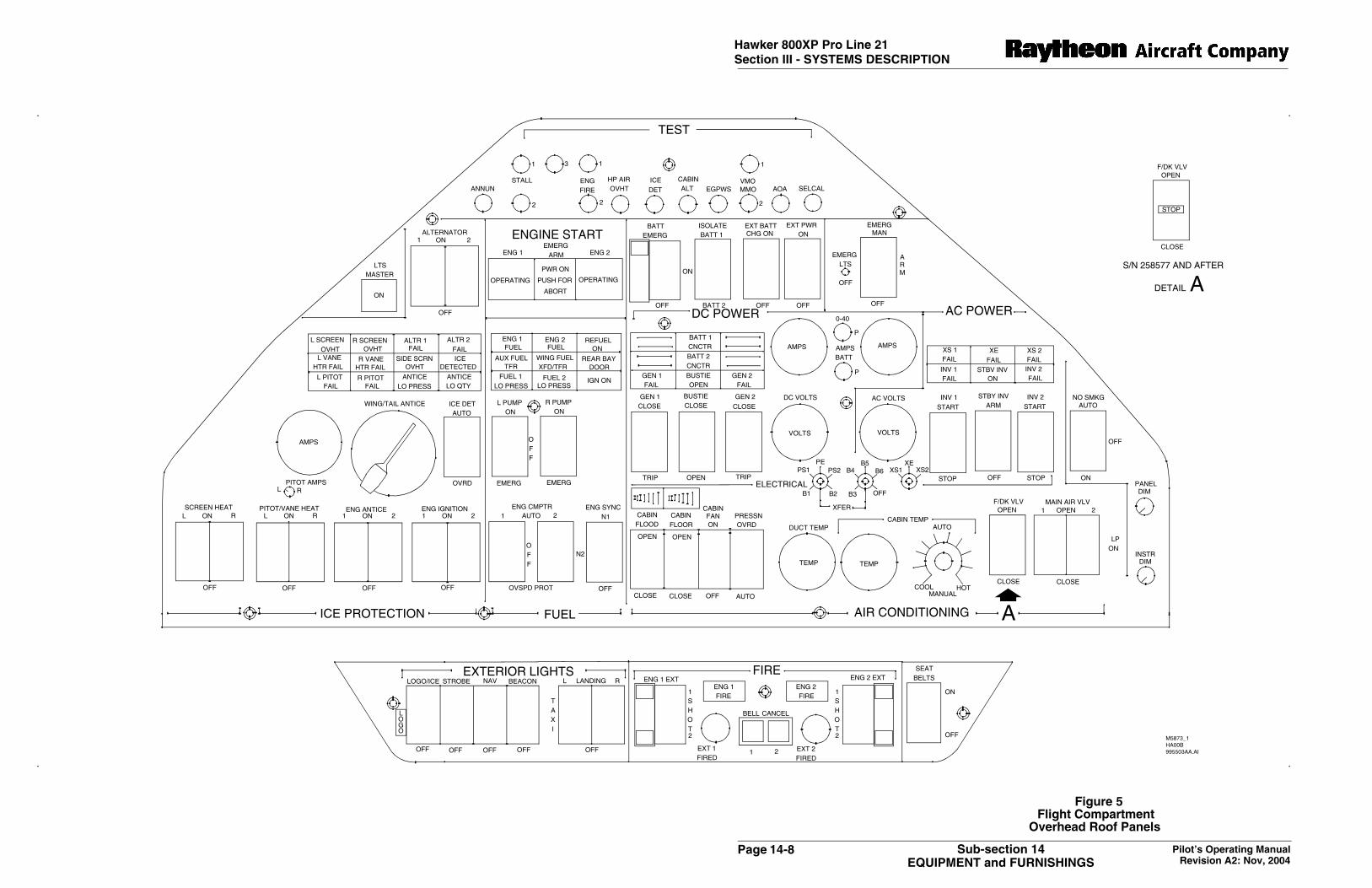
Figure 5Flight Compartment
Overhead Roof Panels

Page 14-9Pilot’s Operating ManualOriginal Issue: Feb, 2002
Sub-section 14EQUIPMENT and FURNISHINGS
Hawker 800XP Pro Line 21Section III - SYSTEMS DESCRIPTION
V8636_1.AI
SIL
ICA
GE
LV
IEW
ING
WIN
DO
WS
HE
AD
SE
TS
TO
WA
GE
HO
OK
ST
ALL
IDE
NT
DIA
GN
OS
TIC
PA
NE
LP
AS
SE
NG
ER
OX
YG
EN
SU
PP
LYV
ALV
E
SIL
ICA
GE
LV
IEW
ING
WIN
DO
WS
HE
AD
SE
T,O
XY
GE
N&
MA
SK
/MIC
SO
CK
ET
SH
EA
DS
ET
,OX
YG
EN
&M
AS
K/M
ICS
OC
KE
TS
FIR
EE
XT
ING
UIS
HE
R
FLA
SH
LIG
HT
LIF
EJA
CK
ET
ST
OW
AG
E
LIF
EJA
CK
ET
ST
OW
AG
E
WA
RN
ING
HO
RN
SU
NV
ISO
RS
ST
OW
AG
E
RA
DIO
AN
DE
LEC
TR
ON
ICE
QU
IPM
EN
T
RU
DD
ER
GU
ST
LOC
K/A
UX
ILIA
RY
HY
DR
AU
LIC
SY
ST
EM
HA
ND
PU
MP
HA
ND
LES
TO
WA
GE
SU
BP
AN
EL
AS
UB
PA
NE
LD
ST
OR
MLA
MP
WA
ND
ER
LAM
PS
WIT
CH
WA
ND
ER
LAM
PS
OC
KE
T
SP
OT
LAM
P&
SW
ITC
H
CR
AS
HA
XE
MA
NU
AL
ST
OW
AG
E
FIR
E-
WA
RN
ING
BE
LL
TR
AY
EN
TR
YLI
GH
TS
WIT
CH
STO
RM
LIG
HT
WA
ND
ER
LIG
HT
SW
ITC
H
STO
RM
LIG
HT
&S
WIT
CH
WA
ND
ER
LIG
HT
SO
CK
ET
Figure 6Flight Compartment (looking aft)
Page 14-10 Pilot’s Operating ManualOriginal Issue: Feb, 2002
Sub-section 14EQUIPMENT and FURNISHINGS
Hawker 800XP Pro Line 21Section III - SYSTEMS DESCRIPTION
M5900HA00B995531AA
INCREASE
DECREASE
L GEAR R GEAR
ISOLATE
PITOT ISOLATION
DEPRESSTO OPERATE
MANUAL CABINALTITUDE CONTROL
NORMAL
NORMAL
PRESSURIZATION CONTROL
TEST
GROUND
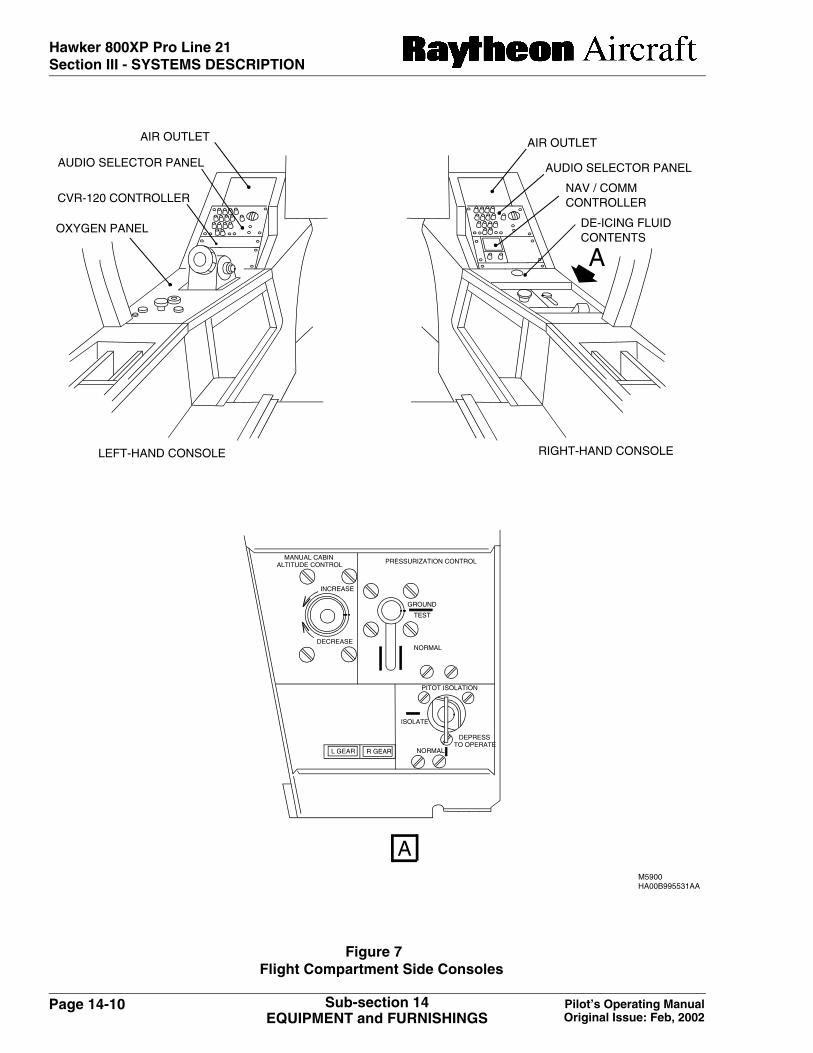
RIGHT-HAND CONSOLELEFT-HAND CONSOLE
OXYGEN PANEL
CVR-120 CONTROLLER
DE-ICING FLUIDCONTENTS
AIR OUTLETAIR OUTLET
AUDIO SELECTOR PANEL AUDIO SELECTOR PANEL
NAV / COMMCONTROLLER
A
A
Figure 7Flight Compartment Side Consoles

Page 14-11Pilot’s Operating ManualOriginal Issue: Feb, 2002
Sub-section 14EQUIPMENT and FURNISHINGS
Hawker 800XP Pro Line 21Section III - SYSTEMS DESCRIPTION
M5851HA00B995480AA
AILERON TRIM
RUDDER TRIM
ELEVATOR TRIMHAND WHEEL
AIR BRAKES
AUXILIARY HYDRAULICSYSTEM SELECTOR
HANDLE
NOSE GEARMECHANICAL
INDICATOR
THRUSTREVERSER
LEVERS
HORN ISOLATEPUSH BUTTON
THROTTLESDUMP VALVE
WHEELBRAKE
SOCKET FOREMERGENCY HYDRAULIC
HAND PUMP
EMERGENCY HYDRAULICHAND PUMP HANDLE
(GUST LOCK BAR)
STOWAGE ON RH SEATSUPPORT STRUCTURE
L.P. COCKS
H.P. COCKS
FIRE WARNINGLIGHTS
FLAPS
L.P. COCKS GUARD
AUXILIARY FUELTRANSFER CONTROL
WING FUELCROSSFEED AND
TRANSFER CONTROL
OATSMOKE
FWDPUSHFUELTEMP
ON ON ON
OFF
SHUT
FLAPS
0
15
o
o
o
o
25
45
PAGE ADV
LINE ADV
CKLSTON/OFF
OPEN
DUMP
AILERON TRIM
RUDDER TRIM
PULL
AUX
HYD
SYSTEM
A
I
R
B
R
A
K
ENOSE UP
OFF OA RUDDER BIAS B
ELEVATORTRIM
NOSE DOWN
T0CG 1/2
3525
15
21
Figure 8Flight Compartment Center Pedestal
STOWAGE BEHINDCOPILOT SEAT
THRUSTLEVERS

Page 14-12 Pilot’s Operating ManualOriginal Issue: Feb, 2002
Sub-section 14EQUIPMENT and FURNISHINGS
Hawker 800XP Pro Line 21Section III - SYSTEMS DESCRIPTION
GALLEY
The galley is located on the left side of the airplane aft of the entry door and consists of liquid containers,hot cup, decanter rack, drain dish, ice drawer, glasses drawer, cold food box, hot meal oven, waste binand various drawers and cupboards.
Electrical supplies are provided to the oven, hot cup, hot beverage container, drain heater andrefreshment cabinet light. The drain dish is connected to an overboard drain. A heater is attached to thedrain pipe immediately inboard of the drain exit from the fuselage. Control of the galley functions isprovided by a galley switch panel located on the upper left of the galley.
M6356_0HA03C014655AA.
CUSTOM WATER CONTAINER
CUPDISPENSERS
WASTE
COFFEEBREWER
SWITCH PANEL
MICROWAVE
COUNTERSTORAGE
SANDWICHTRAY
DRAWER
UTENSILS
CONDIMENTS
PULL OUT WORK
SURFACE
BOWLS
PLATES
MINIATURES
WINE / SPIRITS STORAGE
MISC.STORAGE
NAPKINS
SODA CANS
ICE / COLD STORAGE
GALLEYUP
LIGHTS
GALLEY SWITCH PANEL
GALLEYWORK
LIGHTS
COFFEEHEAT
WATERHEAT
Figure 9Typical Galley
MISCELLANEOUSSTORAGE
MINIATURES
Page 14-13Pilot’s Operating ManualRevision A1: Nov, 2002
Sub-section 14EQUIPMENT and FURNISHINGS
Hawker 800XP Pro Line 21Section III - SYSTEMS DESCRIPTION
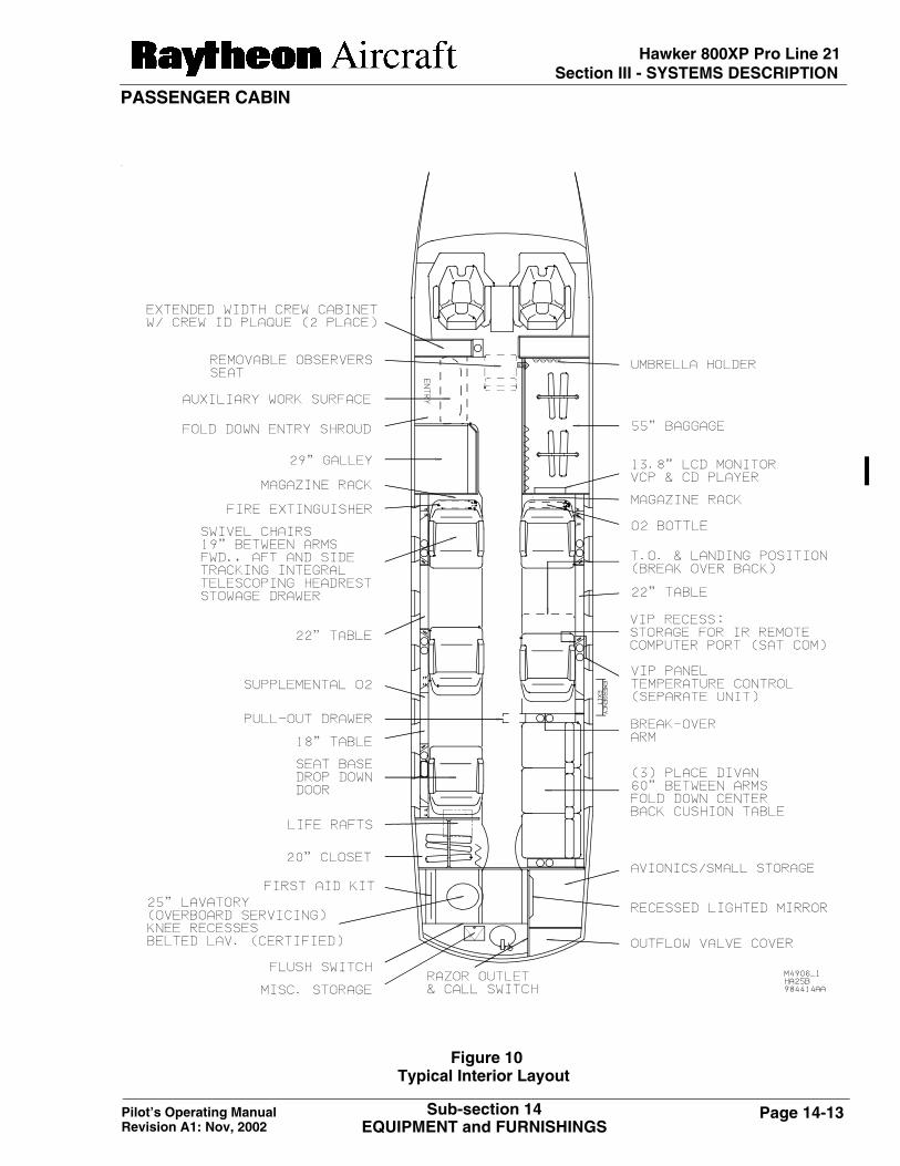
PASSENGER CABIN
Figure 10Typical Interior Layout
Page 14-14 Pilot’s Operating ManualRevision A1: Nov, 2002
Sub-section 14EQUIPMENT and FURNISHINGS
Hawker 800XP Pro Line 21Section III - SYSTEMS DESCRIPTION
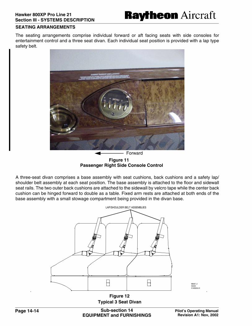
SEATING ARRANGEMENTS
The seating arrangements comprise individual forward or aft facing seats with side consoles forentertainment control and a three seat divan. Each individual seat position is provided with a lap typesafety belt.
A three-seat divan comprises a base assembly with seat cushions, back cushions and a safety lap/shoulder belt assembly at each seat position. The base assembly is attached to the floor and sidewallseat rails. The two outer back cushions are attached to the sidewall by velcro tape while the center backcushion can be hinged forward to double as a table. Fixed arm rests are attached at both ends of thebase assembly with a small stowage compartment being provided in the divan base.
Figure 11Passenger Right Side Console Control
Forward
M6357_0HA03C014656AA.AI
LAP/SHOULDER BELT ASSEMBLIES
Figure 12Typical 3 Seat Divan

Page 14-15Pilot’s Operating ManualOriginal Issue: Feb, 2002
Sub-section 14EQUIPMENT and FURNISHINGS
Hawker 800XP Pro Line 21Section III - SYSTEMS DESCRIPTION
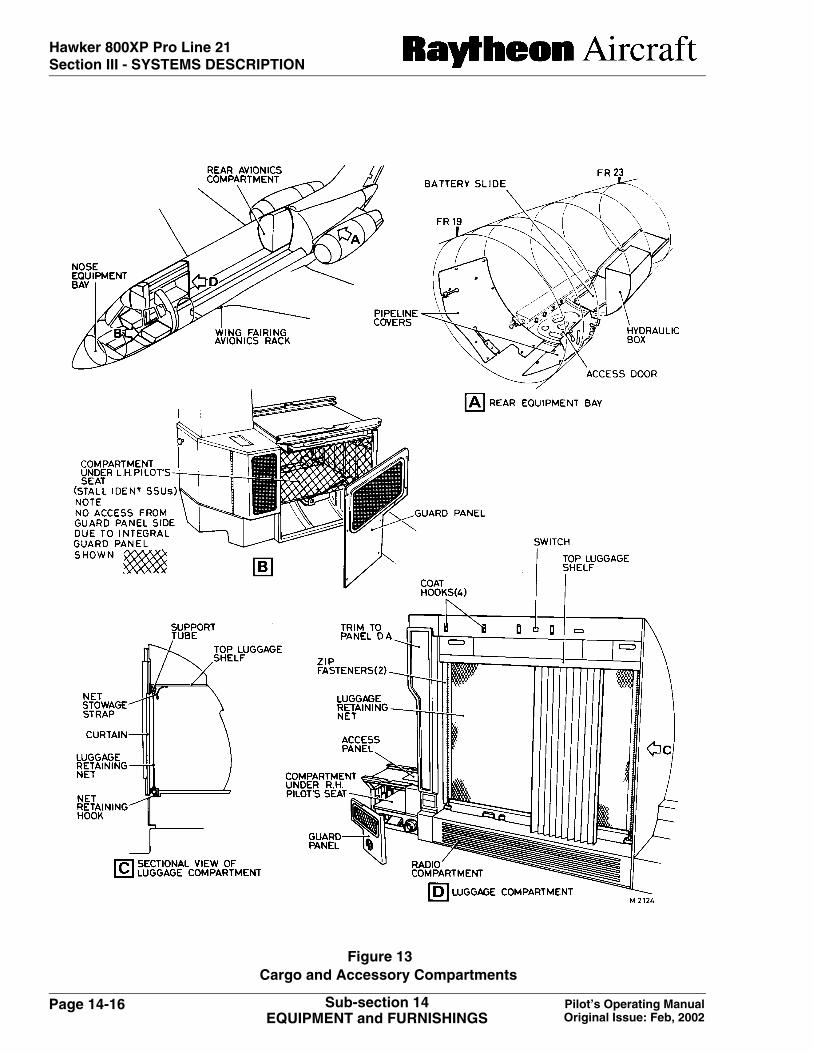
CARGO and ACCESSORY COMPARTMENTS
LUGGAGE COMPARTMENT
A luggage compartment is installed in the vestibule area of all airplanes, with luggage retained withinthe compartment by a zip fastened nylon net. The compartment is normally enclosed by a folding slattype curtain.
A loading label, giving each compartments capacity and maximum floor loadings, is attached to theinterior trim panels.
MAIN RADIO/AVIONICS COMPARTMENTS
Radio racks and structure for the installation of electronic equipment are provided at various locations,such as under each pilot seat structure, under the luggage compartment, in the wing fairing avionicsrack and in the rear avionics compartment.
Flight Compartment Seats
Access to the compartment under the pilot seat structure is via a grill guard panel. Access to thecompartment under the copilot seat is via a grill guard panel inboard of the seat structure and a panelon the top of the seat structure.
Luggage Compartment
The radio compartment under the luggage compartment is concealed by trim panels which can beremoved for maintenance purposes.
Wing Fairing
Equipment in the wing fairing avionics rack is accessible by removing two panels on the fairingunderside.
Rear Avionics Bay
Access to rear avionics compartment is provided by two doors in the toilet compartment and one doorin the rear luggage bay forward bulkhead.
Nose Equipment Bay
The unpressurized nose equipment bay houses the nose landing gear and various avionics boxes. Thenose equipment bay can be accessed either through the nose cone (after removing the weather radar)or through two access panels located on either side of the nose structure aft of the nose cone. A metalsplash guard protects the equipment in the bay and a shield attached over the bay forward openingsimilarly protects the weather radar scanner.
Rear Equipment Bay
The rear equipment bay is unpressurized and access to the bay, via a hinged door on the underside ofthe fuselage, is only possible with the airplane on the ground. Pipelines forward of the access door, areenclosed by covers secured with quick-release fasteners. A box structure on the left-hand side of thebay houses main hydraulic system components.
Page 14-16 Pilot’s Operating ManualOriginal Issue: Feb, 2002
Sub-section 14EQUIPMENT and FURNISHINGS
Hawker 800XP Pro Line 21Section III - SYSTEMS DESCRIPTION
Figure 13Cargo and Accessory Compartments

Page 14-17Pilot’s Operating ManualOriginal Issue: Feb, 2002
Sub-section 14EQUIPMENT and FURNISHINGS
Hawker 800XP Pro Line 21Section III - SYSTEMS DESCRIPTION
TOILET COMPARTMENT
The typical toilet compartment consists of a console assembly, flushing toilet with a fore and aftpositioned toilet services bulkhead. Access is provided to the rear baggage compartment and theavionics compartment from within the toilet compartment.
The washbasin console is installed on the right side and incorporates washing facilities, provision fortoilet requisites and the filling point for the wash water tank.
The toilet service’s bulkhead forms the mounting structure for a hinged mirror (to provide access to anavionics compartment/baggage compartment), an electric razor stowage socket and switch, an airlouver, mirror lamps and switch.
Electrical supplies to the razor socket are taken via a static inverter mounted in the avionicscompartment behind the hinged mirror. Water is pumped from a heated water tank below the washbasin.
Figure 14
AIR LOUVER
Typical Toilet Compartment
Page 14-18 Pilot’s Operating ManualOriginal Issue: Feb, 2002
Sub-section 14EQUIPMENT and FURNISHINGS
Hawker 800XP Pro Line 21Section III - SYSTEMS DESCRIPTION
Intentionally left blank